Embed Size (px)
Citation preview

4G LTE CAT 1 & CAT 4 NL-SW-LTE-S7588 NL-SW-LTE-S7648 NL-SW-LTE-S7618RD Skywire® Family User Manual NimbeLink Corp Updated: June 2018
PN 30229 rev 9 © NimbeLink Corp. 2018. All rights reserved. 1
Table of Contents Table of Contents 2
1. Introduction 3 1.1 Orderable Part Numbers 3 1.2 Product Overview 3 1.3 Block Diagram 4 1.4 Data Plans 4
2. Connect to Kit using a PC 5 2.1 Unpack Kit Contents 6 2.2 Skywire Placement 6 2.3 Attach Antenna to Baseboard 8 2.4 Ensure header J6 is shorted with 2 pin Jumper 9 2.5 Plug in 12V Power Supply to connector J15 9 2.6 Plug USB cable into connector J14 and PC 10 2.7 Press and hold button S1 to power on the modem 10 2.8 Open Tera Term or similar terminal emulator 12 2.9 Test Serial Communication 12 2.10 Test Signal Strength 13 2.11 Activate Modem (one-time step) 14 2.14 Setup PDP Context 15 2.15 Test Network Communication 17
3. APN Setup 18 3.1 Introduction 18 3.2 Common Verizon APNs 18 3.2 Common AT&T/T-Mobile APNs 18
4. Common Next Steps 19
5. Additional Resources 19
PN 30229 rev 9 © NimbeLink Corp. 2018. All rights reserved. 2

1. Introduction 1.1 Orderable Part Numbers
Orderable Device Description Carrier Network
Type NL-SWDK Skywire Development Kit Any Any
NL-SW-LTE-S7618RD LTE CAT1, Verizon Verizon LTE
NL-SW-LTE-S7648 LTE CAT1, AT&T/T-Mobile AT&T, T-Mobile, etc. LTE
NL-SW-LTE-S7588-V LTE CAT4, Verizon Verizon LTE
NL-SW-LTE-S7588-V-B LTE CAT4, Verizon Verizon LTE
NL-SW-UAV-S7588 LTE CAT4, Verizon Verizon LTE
NL-SW-LTE-S7588-T LTE CAT4, AT&T/T-Mobile, HSPA AT&T, T-Mobile, etc. LTE
NL-SW-LTE-S7588-T-C LTE CAT4, AT&T/T-Mobile, HSPA AT&T, T-Mobile, etc. LTE
NL-SIM-ATT 3FF SIM for AT&T AT&T GSM/LTE
NL-SIM-TMO 3FF SIM for T-Mobile T-Mobile GSM/LTE
NL-SIM-VOD 3FF SIM for Vodafone Vodafone GSM/LTE
NL-SIM-COM 3FF SIM for Verizon Verizon LTE
TG.30.8113 Taoglas Antenna Any
CAB.011 Taoglas SMA to UFL cable
1.2 Product Overview This documents details interfacing with the 4G LTE CAT 1 & CAT 4 NL-SW-LTE-S7xxx family of Skywire® modems for Verizon or AT&T on the Skywire Development Kit. The Skywire Development Kit includes one baseboard, antenna, power supply, SIM cards, and debug cables. Skywire modems must be purchased separately. The kit enables you to develop your application directly on the Skywire modem with three different ways to connect: ● Connect your PC to the Skywire modem UART port via onboard USB-to-UART
converter and send AT commands directly to the modem through PC terminal applications. You can also connect over USB for access to multiple COM ports.
● The kit is an Arduino shield, so you can plug the kit directly onto an Arduino microcontroller. Please see Section 3: Common Next Steps for links to example documentation.
● To connect the kit to a different processor or development kit, a 14-pin header breaks out the necessary signals for easy connection to any device. The modem supports I/O levels from 1.65-5.5V, simplifying connection to other systems.
PN 30229 rev 9 © NimbeLink Corp. 2018. All rights reserved. 3
Skywire modems and development kits are sold separately. Users will need to activate a data plan through the carrier of their choice to allow the Skywire to connect to the network. Data plans may be activated at go.nimbelink.com.
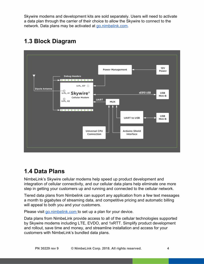
1.3 Block Diagram
1.4 Data Plans NimbeLink’s Skywire cellular modems help speed up product development and integration of cellular connectivity, and our cellular data plans help eliminate one more step in getting your customers up and running and connected to the cellular network. Tiered data plans from Nimbelink can support any application from a few text messages a month to gigabytes of streaming data, and competitive pricing and automatic billing will appeal to both you and your customers. Please visit go.nimbelink.com to set up a plan for your device. Data plans from NimbeLink provide access to all of the cellular technologies supported by Skywire modems including LTE, EVDO, and 1xRTT. Simplify product development and rollout, save time and money, and streamline installation and access for your customers with NimbeLink’s bundled data plans.
PN 30229 rev 9 © NimbeLink Corp. 2018. All rights reserved. 4

2. Connect to Kit using a PC This section covers how to connect your development kit to a PC and provision the modem with your cellular plan. It also covers how to communicate over the serial port to the Skywire modem which only requires the use of USB port and connector marked J14 or USB2 in the diagram below. USB1 (connector J5) is used for high speed data connections and firmware updates to the modem and is not used in this section. The pictures used in this document show the NL-SW-LTE-S7588 Skywire. However, the setup, connections, and processes are identical across the entire NL-SW-LTE-S7xxx family of Skywire modems.
PN 30229 rev 9 © NimbeLink Corp. 2018. All rights reserved. 5

2.1 Unpack Kit Contents
2.2 Skywire Placement To mount your Skywire Cellular modem follow these steps:
1. Gather the following:
a. Skywire Development Kit board b. 4G LTE CAT 1 & CAT 4 NL-SW-LTE-S7xxx Skywire Cellular Modem c. U.FL extractor tool (Always use a U.FL extractor tool when placing or
removing U.FL cables on the Skywire modem to avoid damaging the U.FL connectors).
b. 3FF SIM card
2. Insert the SIM card into the SIM Card socket on the Skywire. The metal contacts should be inserted so they are facing the Skywire's circuit board. As shown in the image on the right.
PN 30229 rev 9 © NimbeLink Corp. 2018. All rights reserved. 6

3. Line up your Skywire’s cellular U.FL connector(s) on the side of the board closest to the antenna connector. Then carefully seat your Skywire into the board’s Skywire socket (U1). Take care to ensure that the pins are correctly aligned. Failure to properly align the pins may damage your Skywire.
A common issue is accidentally inserting the modem with pins misaligned by one row. Check pin alignment BEFORE applying power to prevent modem damage.
4. To avoid damage to the U.FL connector and maximize connector life, a U.FL removal tool should be used when attaching/removing the U.FL connector. Always insert and remove the U.FL connector with a force perpendicular to the board.
5. Attach the U.FL cable to the top U.FL connector X1 on the Skywire. The x1
connection on the Skywire is for the primary cellular antenna. Attach a second antenna (sold separately, not pictured) to connector X2 to connect the diversity cellular antenna.
PN 30229 rev 9 © NimbeLink Corp. 2018. All rights reserved. 7

A properly mounted Skywire NL-SW-LTE-S7xxx modem with U.FL cable attached to top U.FL connector X1
2.3 Attach Antenna to Baseboard Antenna screws onto SMA connector with a clockwise rotation
PN 30229 rev 9 © NimbeLink Corp. 2018. All rights reserved. 8

2.4 Ensure header J6 is shorted with 2 pin Jumper
This enables USB to UART communication between the PC and the modem.
2.5 Plug in 12V Power Supply to connector J15
-LED's D4 and D5 will illuminate on the development kit (not pictured)
PN 30229 rev 9 © NimbeLink Corp. 2018. All rights reserved. 9

2.6 Plug USB cable into connector J14 and PC
-LED D3 on the development kit will illuminate (not pictured)
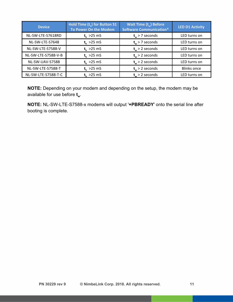
2.7 Press and hold button S1 to power on the modem
Please see the table below for the length of time needed to hold down button S1 for your particular modem.
PN 30229 rev 9 © NimbeLink Corp. 2018. All rights reserved. 10
Device Hold Time (th) for Button S1
To Power On the Modem Wait Time (tw) Before
Software Communication* LED D1 Activity
NL-SW-LTE-S7618RD th >25 mS tw > 7 seconds LED turns on
NL-SW-LTE-S7648 th >25 mS tw > 7 seconds LED turns on
NL-SW-LTE-S7588-V th >25 mS tw > 2 seconds LED turns on
NL-SW-LTE-S7588-V-B th >25 mS tw > 2 seconds LED turns on
NL-SW-UAV-S7588 th >25 mS tw > 2 seconds LED turns on
NL-SW-LTE-S7588-T th >25 mS tw > 2 seconds Blinks once
NL-SW-LTE-S7588-T-C th >25 mS tw > 2 seconds LED turns on
NOTE: Depending on your modem and depending on the setup, the modem may be available for use before tw.
NOTE: NL-SW-LTE-S7588-x modems will output '+PBREADY' onto the serial line after booting is complete.
PN 30229 rev 9 © NimbeLink Corp. 2018. All rights reserved. 11

2.8 Open Tera Term or similar terminal emulator If you do not have a terminal emulator program, you can get Tera Term here: http://logmett.com/index.php?/download/tera-term-486-freeware.html Your PC may have multiple COM ports. Select appropriate USB COM port to communicate with the development kit.
Serial Settings should be as follows (these are the default settings): Baud Rate: 115,200 bps Data: 8bit Parity: none Stop: 1bit Flow Control: none
2.9 Test Serial Communication In the terminal program, type the command:
AT followed by the Enter key, and the terminal should respond with:
OK
Note: You may need to turn echo on in order to see what you are typing. If you type the command:
AT and don’t see it being typed on your screen, hit the Enter key, and type the following command:
ATE1 followed by the Enter key, and the terminal program should respond with:
OK Type the following command:
AT to verify you can see the command you are typing. After pressing the Enter key, the terminal program will respond with:
OK
PN 30229 rev 9 © NimbeLink Corp. 2018. All rights reserved. 12

2.10 Test Signal Strength In the terminal program, type the command:
AT+CESQ followed by the Enter key, and the terminal should respond with:
+CESQ: aa,bb,ccc,ddd,xx,yy The important parameters are the last two. xx is the Reference Signal Received Quality (RSRQ) and yy is the Reference Signal Received Power (RSRP). Typical values are as follows:
Values of xx RSRQ (Reference Signal Received Quality)
0 RSRQ < -19.5 dB
1 -19.5 dB ≤ RSRQ < -19 dB
2 -19 dB ≤ RSRQ < -18.5 dB
... ...
32 -4 dB ≤ RSRQ < -3.5 dB
33 -3.5 dB ≤ RSRQ < -3 dB
34 -3 dB ≤ RSRQ
255 Not known or detectable
Values of yy RSRP (Reference Signal Received Power)
0 RSRP < -140 dBm
1 -140 dBm ≤ RSRP < -139 dBm
2 -139 dBm ≤ RSRP < -138 dBm
...
95 -46 dBm ≤ RSRP < -45 dBm
96 -45 dBm ≤ RSRP < -44
97 -44 dBm ≤ RSRP
255 Not known or not detectable
Here are estimated signal qualities based on the above values:
Values of xx RSRQ Values of yy RSRP Quality
0 RSRQ < -19.5 dB 0 - 40 RSRP < -100 dBm Marginal
1 - 9 -19.5 dB ≤ RSRQ < -15 dB 41 - 50 -100 dBm ≤ RSRP < -90 dBm Fair
10 - 19 -15 dB ≤ RSRQ < -10 dB 51 - 59 -90 dBm ≤ RSRP < -80 dBm Good
20 - 34 ≥ -10 dB 60 - 97 ≥ -80 dBm Excellent
PN 30229 rev 9 © NimbeLink Corp. 2018. All rights reserved. 13
Note: The NL-SW-LTE-S7xxx family calculates the CSQ value differently than other Skywire modems. Therefore, we recommend using the command AT+CESQ to verify signal strength and quality.
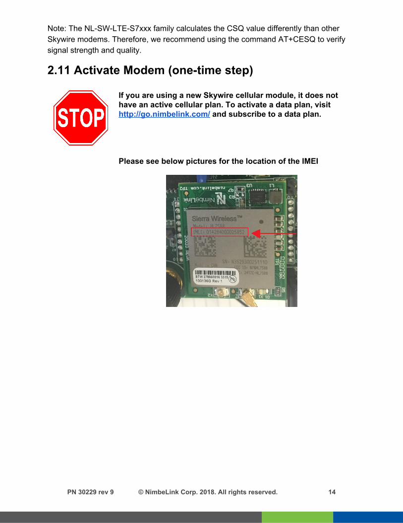
2.11 Activate Modem (one-time step)
If you are using a new Skywire cellular module, it does not have an active cellular plan. To activate a data plan, visit http://go.nimbelink.com/ and subscribe to a data plan.
Please see below pictures for the location of the IMEI
PN 30229 rev 9 © NimbeLink Corp. 2018. All rights reserved. 14

2.14 Setup PDP Context Before you can successfully communicate with the network using a LTE Skywire, you need to define the PDP context. 2.14.1 For NL-SW-LTE-S7648 and NL-SW-LTE-S7588-T (AT&T/GSM Firmware):
In the terminal program, type the command: AT+CGDCONT = 1,"IP","APN","",0,0,0,0,0,0
where APN is the individual APN for your network, followed by the Enter key, and the terminal program should respond with: OK Note: Consult Section 3: APN Setup for help with your APN. To verify that the APN was set correctly, in the terminal program type the command:
AT+CGDCONT? followed by the Enter key, and the terminal should respond with:
+CGDCONT: 1,"IP","APN","",0,0,0,0,0,0 as well as the other PDP context information on the device. Once the APN is correct, the Skywire will automatically activate the PDP context and get an IP address. You can check with by issuing:
AT+CGDCONT? and looking for the IP address after the APN you just entered:
+CGDCONT: 1,"IP","APN","<IP Address>",0,0,0,0,0,0 If you do not get an IP address, you can enable this setting. In the terminal program type the command:
AT+CGACT=1,1 followed by the enter key, and the terminal should respond with:
OK To verify the modem successfully connected to the network type
AT+CGDCONT? followed by the enter key, and the terminal should respond with:
+CGDCONT: 1,"IP","APN","<IP Address>",0,0,0,0,0,0 where <IP Address> is the Skywire modem’s IP address. If the AT+CGACT command does not work, the terminal will respond with
+CME ERROR: <Error Number>
PN 30229 rev 9 © NimbeLink Corp. 2018. All rights reserved. 15

and further setup may be necessary. Check the signal strength with AT+CESQ to verify the Skywire is getting an acceptable signal. Otherwise, consult the Sierra AT Command Reference Guide for your particular error number.
2.14.2 For the NL-SW-LTE-S7618RD and NL-SW-LTE-S7588-V (Verizon Firmware): In the terminal program, type the command:
AT+CGDCONT = 3,"IP","APN","",0,0,0,0,0,0 where APN is the individual APN for your network, followed by the Enter key, and the terminal program should respond with: OK Note: Consult Section 3: APN Setup for help with your APN. Verizon devices should always define the APN in context 3. To verify that the APN was set correctly, in the terminal program type the command:
AT+CGDCONT? followed by the Enter key, and the terminal should respond with:
+CGDCONT: 3,"IP","APN","",0,0,0,0,0,0 as well as the other PDP context information on the device. To enable this setting, in the terminal program type the command:
AT+CGACT=1,3 followed by the enter key, and the terminal should respond with:
OK To verify the modem successfully connected to the network type
AT+CGDCONT? followed by the enter key, and the terminal should respond with:
+CGDCONT: 3,"IP","APN","<IP Address>",0,0,0,0,0,0 where <IP Address> is the Skywire modem’s IP address. If the AT+CGACT command does not work, the terminal will respond with
+CME ERROR: <Error Number> and further setup may be necessary. Check the signal strength with AT+CESQ to verify the Skywire is getting an acceptable signal. Otherwise, consult the Sierra AT Command Reference Guide for your particular error number.
PN 30229 rev 9 © NimbeLink Corp. 2018. All rights reserved. 16

2.15 Test Network Communication In the terminal program, type the command:
AT+CGREG? followed by the Enter key, and the terminal should respond with:
+CGREG: 0,1 or +CGREG: 0,5 For all other responses, review network status responses in the AT Command Manual.
Reset power, and repeat steps 2.5 through 2.15 (as applicable) before moving on to Section 3.
PN 30229 rev 9 © NimbeLink Corp. 2018. All rights reserved. 17

3. APN Setup 3.1 Introduction GSM and LTE-based Skywire modems can be setup to use different APNs. For Skywires that use AT&T and T-Mobile service, the correct APN is often needed to register on the network and pass data. For Verizon Skywires, it may be beneficial to use a setup that necessitates using a different APN.
3.2 Common Verizon APNs The most common reason for needing a different APN is because you are using a particular IP address type. If you activated your Skywire modem on https://go.nimbelink.com, it uses a Private IP address and the APN:
NIMBLINK.GW12.VZWENTP If you have changed your IP address type to a Public Dynamic IP address, the APN will be:
VZWINTERNET Finally, if you have changed your IP address type to a Public Static IP address, the APN is most likely:
MW01.VZWINTERNET However, it may be different depending on your location. For changing your IP address type, or to get your APN, please contact us at [email protected]. Please include the following information:
- IMEI of your Skywire modem - Model of your Skywire modem - SIM ID of your SIM card
If you activated your service for your Skywire from Verizon directly or another carrier, please contact your representative at that company for the APN you should use.
3.2 Common AT&T/T-Mobile APNs Cellular carries based on AT&T and T-Mobile service requires using a unique APN to register on the network and pass data. If you activated your Skywire modem on https://go.nimbelink.com, here are the following APNs to use: AT&T Service 10569.mcs
PN 30229 rev 9 © NimbeLink Corp. 2018. All rights reserved. 18
T-Mobile Service c1.korem2m.com If you activated your service for your Skywire from AT&T or T-Mobile directly or another carrier, please contact your representative at that company for the APN you should use.
4. Common Next Steps Once the network setup and testing is complete, you are ready to start developing with your Skywire modem. Common application examples include sending and receiving SMS messages, FTP file transfer, TCP/UDP packets, and using the modem with an external microcontroller, such as an Arduino. Please consult these application notes on the modem’s product webpage for specific examples of each type of operation.
5. Additional Resources ● 4G LTE Cat 1 NL-SW-LTE-S7618RD Skywire Product Page ● 4G LTE Cat 1 NL-SW-LTE-S7618RD Skywire Datasheet ● 4G LTE Cat 1 NL-SW-LTE-S7648 Skywire Product Page ● 4G LTE Cat 1 NL-SW-LTE-S7648 Skywire Datasheet ● 4G LTE Cat 4 Skywire Product Page ● 4G LTE Cat 4 Skywire Datasheet ● Sending SMS ● Configuring linux 'pppd' ● Sending and Receiving data using socket dial ● 4G LTE Cat 4 Firmware Update Process ● Sierra's HL7618RD Product Technical Resources ● Sierra's HL7618RD AT Command Manual ● Sierra's HL7648 Product Technical Resources ● Sierra's HL7648 AT Command Manual ● Sierra’s HL7588 Product Technical Resources ● Sierra's HL7588 AT Command Manual
PN 30229 rev 9 © NimbeLink Corp. 2018. All rights reserved. 19


![Real World Performance of LTE Downlink in a Static Dense ...indicators: RSRP, RSSI, RSRQ, and SINR; see [5]. RSRP serves as the main indicator for cell selection during the initial](https://img.dokumen.tips/doc/110x75/60f7fab9c849a8662229f6f6/real-world-performance-of-lte-downlink-in-a-static-dense-indicators-rsrp-rssi.jpg)


![Handover Management in 5G and Beyond: A Topology …repository.kaust.edu.sa/kaust/bitstream/10754/622720/1/07792669.pdf · quality (RSRQ) (see [39] for the HO procedure in LTE). Also,](https://img.dokumen.tips/doc/110x75/5b5c6cb17f8b9ad2198c5dfd/handover-management-in-5g-and-beyond-a-topology-quality-rsrq-see-39-for.jpg)