Embed Size (px)
Citation preview
The ns-3 LTE module CTTC ns-3 team, Mobile Networks Department (Biljana
Bojovic, Lorenza Giupponi, Marco Miozzo, Manuel Requena and Nicola Baldo)

• LENA is a simulation platform for LTE/EPC• Initial development started in 2010 by in the framework of
Google Summer of Code• Developed by the Mobile Network department of CTTC• Main objective:
to allow to design and test Self Organized Network (SON) algorithms and solutions for LTE vendors
The LENA project
2
• A Product-oriented simulator:– designed around an industrial API:
the Small Cell Forum MAC Scheduler Interface Specification– Allows testing of real code in the simulation– Accurate model of the LTE/EPC protocol stack– Specific Channel and PHY layer models for LTE macro and
small cells• An Open source simulator:
– Development open to the community– Fosters early adoption and contributions– Helps building confidence and trust on simulation model– Candidate reference evaluation platform– Based on ns-3– Free and open source licensing (GPLv2)
LENA: an open source product-orientedLTE/EPC Network Simulator
3

Target applications for LENA includethe design and performance evaluation of:
• DL & UL LTE MAC Schedulers• Radio Resource Management Algorithms• Inter-cell interference coordination solutions• Load Balancing and Mobility Management• Heterogeneous Network (HetNets) solutions• End-to-end QoE provisioning• Multi-RAT network solutions• Cognitive LTE systems
LENA: an open source product-orientedLTE/EPC Network Simulator
4

• Support the evaluation of:– Radio-level performance– End-to-end QoE
• Allow the prototyping of algorithms for:– QoS-aware Packet Scheduling – Radio Resource Management– Inter-cell Interference Coordination– Self Organized Networks– Cognitive / Dynamic Spectrum Access
• Scalability requirements:– Several 10s to a few 100s of eNBs– Several 100s to a few 1000s of UEs
LENA High level requirements
5

• Simulation is a tradeoff between:– Detail of the model– Implementation complexity and run-time scalability
• Choose min detail that satisfies requirements– Minimize implementation complexity– Minimize difficulty in using the simulator
Design approach
6

• FemtoForum LTE MAC Scheduler API• Radio signal model granularity: Resource Block
– Symbol-level model not affordable– Simplified Channel & PHY model
• Realistic RLC to use IP from upper layers.• Realistic Data Plane Protocol stack model
– Realistic RLC, PDCP, S1-U, X2-U– Allows for proper interaction with IP networking– Allows for end-to-end QoE evaluations
• Hybrid Control Plane model:– Realistic RRC model– Simplified S1-C, X2-C and S11 models
• Simplified EPC– One MME and one SGW– SGW and PGW in the same node (no S5/S8 interface)
• Focus on connected mode– RRC connected, EMM Registered, ECM connected
(Some) Important Design Choices
7
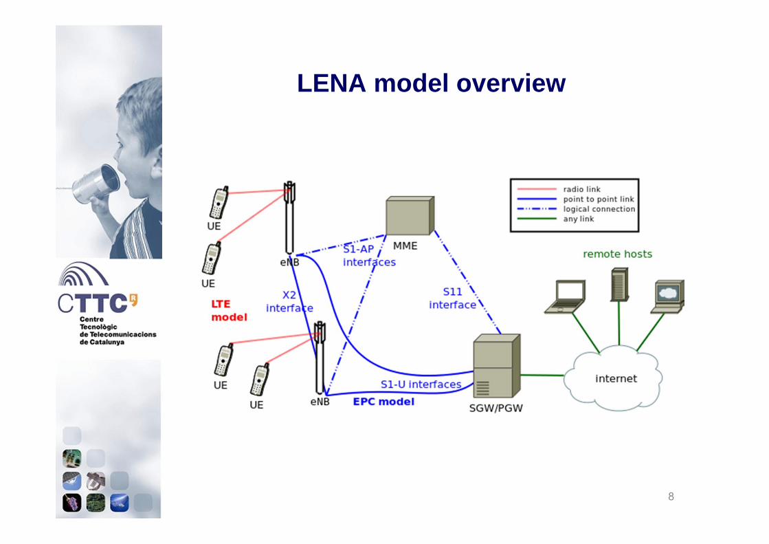
LENA model overview
8

End-to-end Data Plane protocol stack
9

End-to-end Data Plane architecture:data flow in downlink
10

End-to-end Data Plane architecture:data flow in uplink
11

LTE Data Plane protocol stack: UE
12

LTE Data Plane protocol stack: eNB
13

PHY and Channel architecture: UE
14
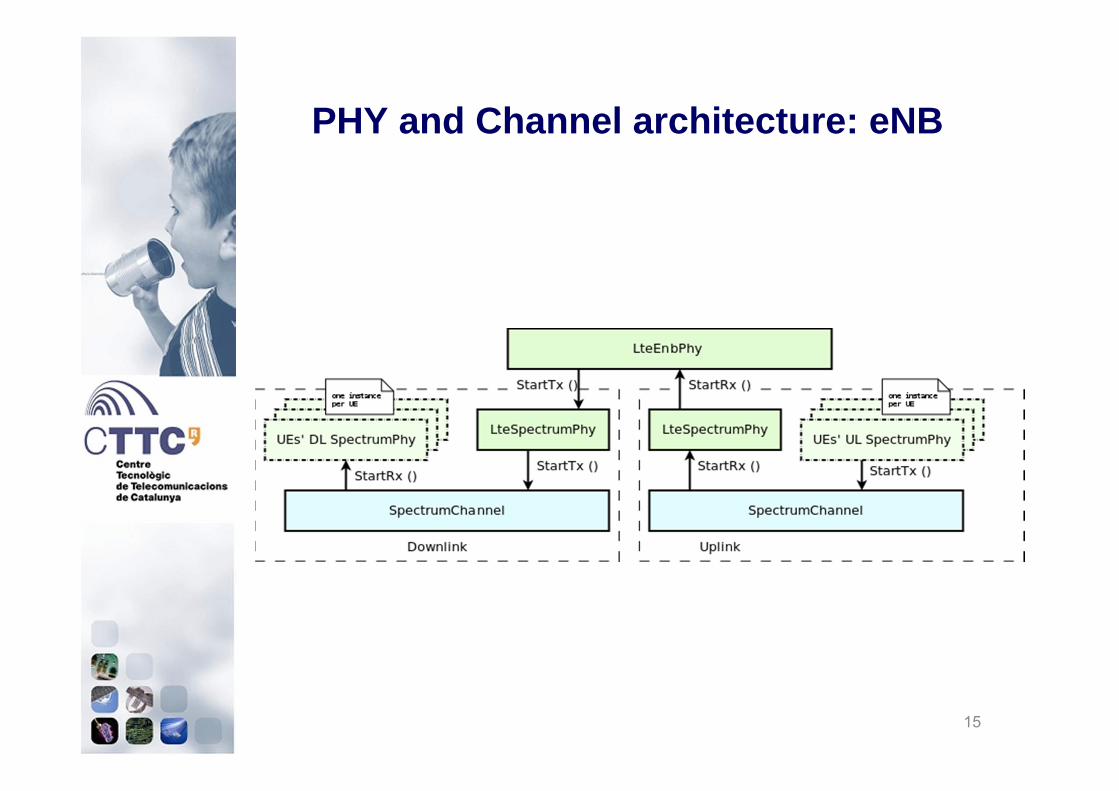
PHY and Channel architecture: eNB
15
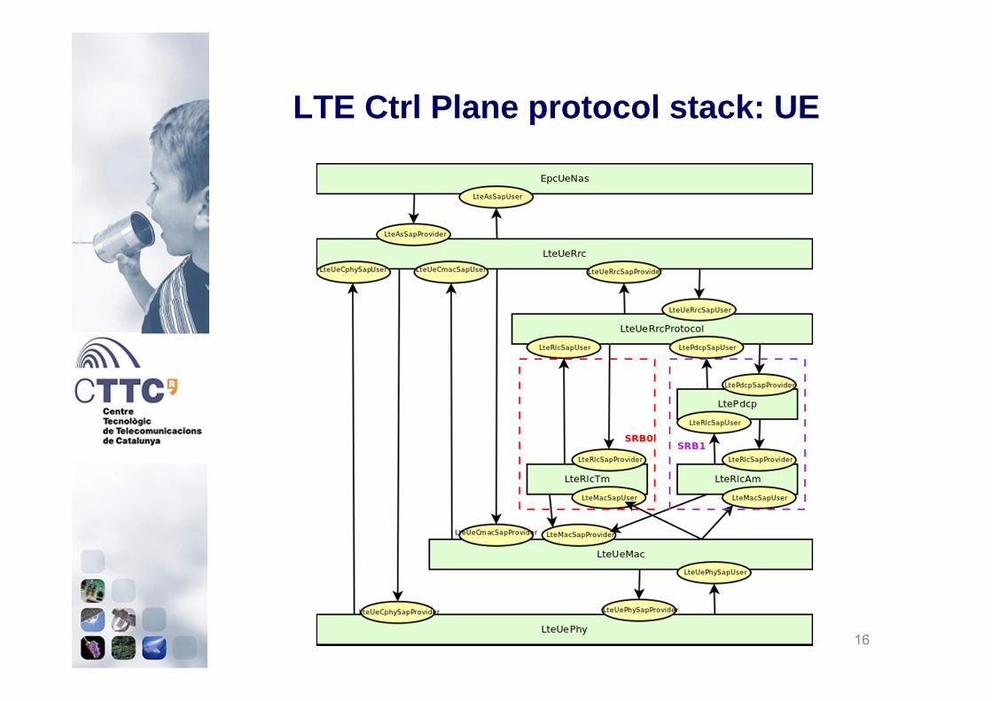
LTE Ctrl Plane protocol stack: UE
16
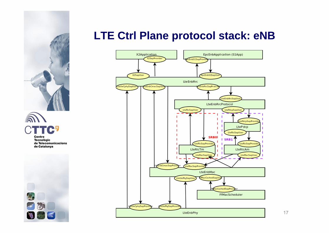
LTE Ctrl Plane protocol stack: eNB
17

EPC Control Plane Architecture
18

EPC Control Plane Architecture
19

EPC Control Plane Architecture
20
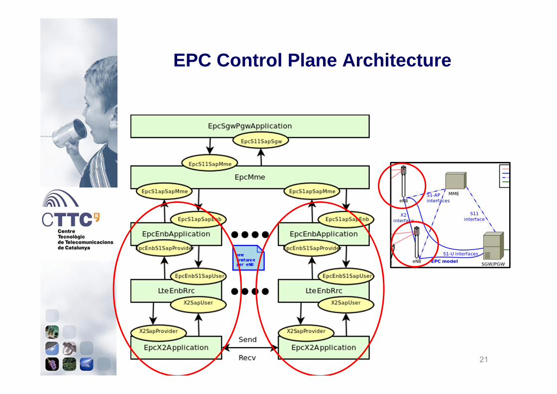
EPC Control Plane Architecture
21

• Included new models for enabling 3GPP-like scenarios– New path loss models (indoor and outdoor)
• External & internal wall losses• Shadowing• Pathloss logic
– Buildings model• Add buildings to network topology
– Antenna models• Isotropic, sectorial (cosine & parabolic shape)
– Fast fading model• Pedestrian, vehicular, etc.
Radio Propagation Models
22

• Okumura Hata: open area pathloss for distances > 1 Km and frequencies ranging from 150 MHz to 2.0 GHz
• Kun empirical model for 2.6 GHz– Sun Kun, Wang Ping, Li Yingze "Path Loss Models for Suburban Scenario at 2.3GHz, 2.6GHz
and 3.5GHz”, 8th International Symposium on Antennas, Propagation and EM Theory (ISAPE), 2008.
• ITU-R P1411 Line-of-Sight (LoS) short range outdoor communication in the frequency range 300 MHz to 100 GHz
– Used for short communication link (< 200 m.)
• ITU-R P1411 Non-Line-of-Sight (NLoS) short range outdoor communication over rooftops in the frequency range 300 MHz to 100 GHz.
– Used for communication link < 1 km
Outdoor Radio Propagation models
23

• Buildings defined as ns3 Box classes with– xMin, xMax, yMin, yMax, zMin, zMax (inherithed by Box)– Number of floors – Number of room in x-axis and y -axis (grid topology)
• Buildings model that allows to “install” building information to mobility model of a node:
– the ns3 Box class containing the building– Position in terms of floors– Position in the grid of rooms– Node condition: indoor vs. outdoor
• ITU-R P1238 implements building-dependent indoor propagation loss model as function of the type of building (i.e., residential, office and commercial)
Buildings model &Indoor Radio Propagation model
24
x
zy

• External wall losses for penetration loss through walls for indoor to outdoor communications and vice-versa (from COST231)
– Wood ~ 4 dB– Concrete with windows (not metallized) ~ 7 dB– Concrete without windows ~ 15 dB (spans between 10 and 20)– Stone blocks ~ 12 dB
• Internal wall losses evaluated assuming that each single internal wall has a constant penetration (5 dB) and evaluating the number of walls
• Log-normal shadowing standard deviation as function of the connection characteristics
– Outdoor σO = 7 – Indoor σI = 10 – External walls penetration σE = 5
• Height gain model when transmitting device is on a floor above the ground (2 dB)
• Pathloss logic chooses correct model depending on nodes positions
Hybrid Propagation Loss Model
25

• LTE supports antenna modeling via ns-3 AntennaModel class.
• Isotropic [default one, for both eNB and UE]• Sectorial (cosine & parabolic shape)
Antenna models
26

• Fast fading model based on pre calculated traces for maintaining a low computational complexity
– Matlab script provided in the code using rayleighchan function– 1 fading value per RB and TTI
• Main parameters:– users’ speed: relative speed between users (affects the Doppler
frequency)– number of taps (and relative power): number of multiple paths
considered– time granularity of the trace: sampling time of the trace.– frequency granularity of the trace: number of RB.– length of trace: ideally large as the simulation time, might be reduced
by windowing mechanism.
Fading model
27
Urban scenario 3 kmph Pedestrian scenario 3 kmph

• Only FDD is modeled• Freq domain granularity: RB • Time domain granularity: 1 TTI (1 ms)• The subframe is divided in frequency into DL & UL
• DL part is made of– control(RS, PCFICH, PDCCH)
– RS is part of the control – data (PDSCH)
• UL part is made of– control and data (PUSCH+PUCCH)– SRS (only wideband periodic)
PHY model
28
RB 1RB 2
RB N
RB 1RB 2
RB N

• LTE Spectrum model: (fc, B) identifies the radio spectrum usage– fc: LTE Absolute Radio Frequency Channel Number– B: Transmission Bandwidth Configuration in number of RB– Supports different frequencies and bandwidths per eNB– UE will automatically use the spectrum model of the eNB it is attached to
• Gaussian Interference model– powers of interfering signals (in linear units) are summed up together to determine the overall
interference power per RB basis
• CQI feedback– periodic wideband CQIs: single value representative for the whole B.– inband CQIs: a set of value representing the channel state for each RB
• In DL evaluated according to the SINR of:– control channel (RS, PDCCH)– data channel when available (PDSCH)
• In UL evaluated according to the SINR of– SRS signal periodically sent by the UEs.– PUSCH with the actual transmitted data.
• Scheduler can filter the CQI according to their nature:– SRS_UL_CQI for storing only SRS based CQIs.– PUSCH_UL_CQI for storing only PUSCH based CQIs.– ALL_UL_CQI for storing all the CQIs received.
Interference and Channel Feedback
29
fc,2
1 2 3 B2
fc,1
1 2 3 B1

PHY Data error model
• Signal processing not modeled accurately use error model• Transport Block error model• Used for PDSCH and PUSCH• Based on Link-to-System Mapping
– SINR measured per Resource Block– Mutual Information Effective SINR Mapping (MIESM)– BLER curves from dedicated link-level LTE simulations– Error probabilty per codeblock– Multiple codeblocks per Transport Block
30
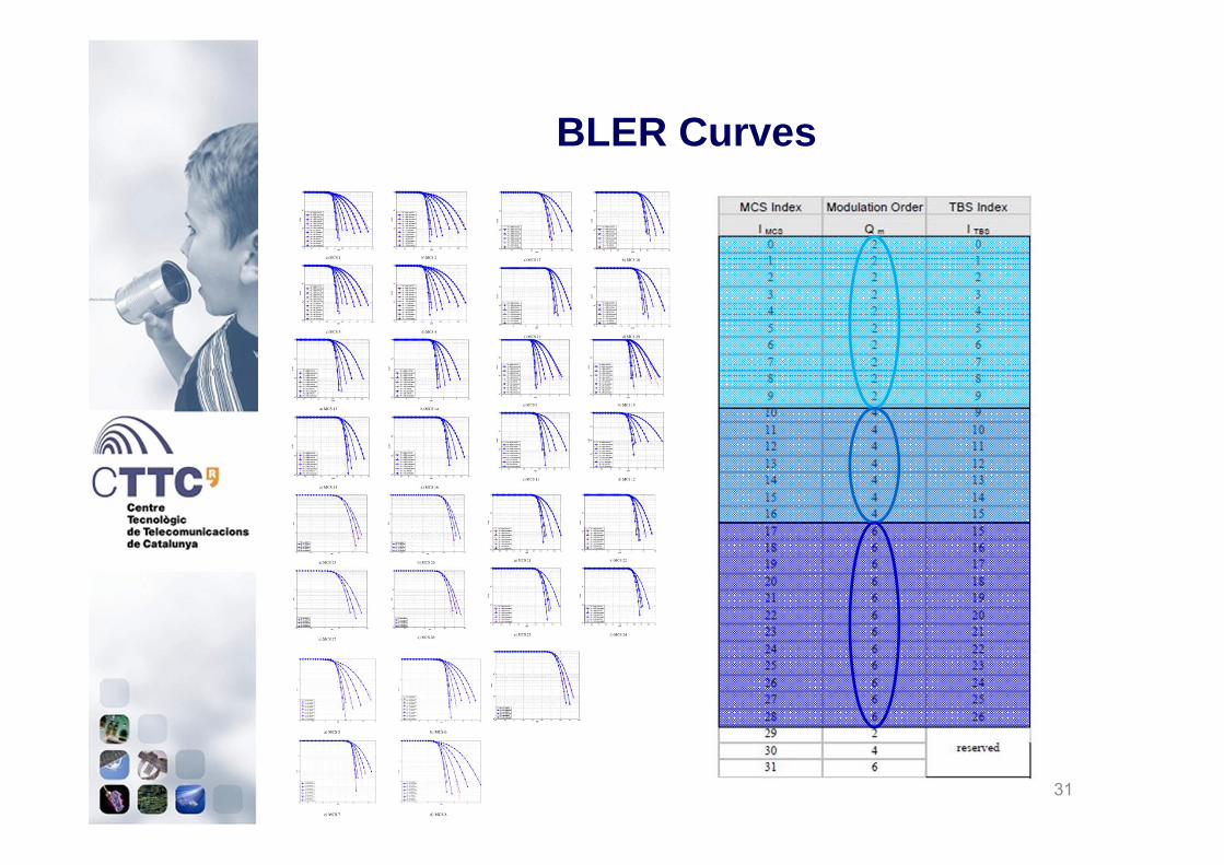
BLER Curves
31
• Error model only for downlink, while uplink has an error-free channel
• Based on an evaluation study carried out in the RAN4 (R4-081920)
• Evaluated according to the equivalent SINR perceived in the whole bandwidth of PCFICH+PDCCH with MIESM model
• In case of error correspondent DCIs are discarded and data will not be decoded
PHY DL Control error model
32
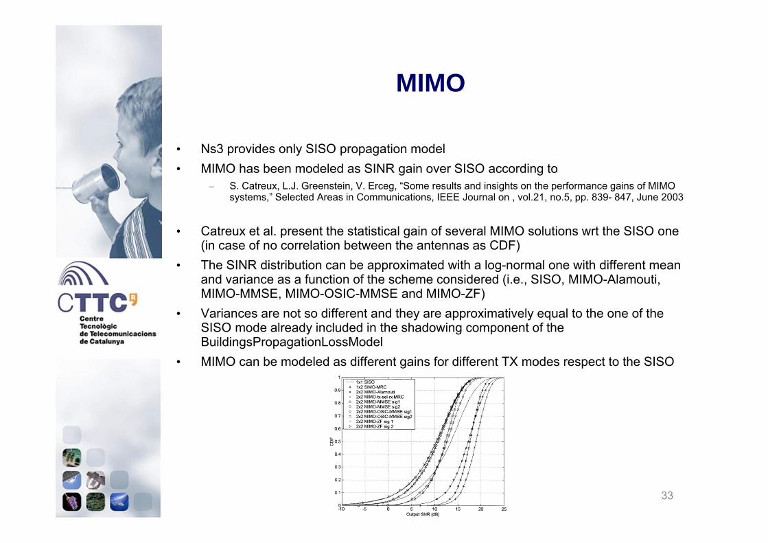
• Ns3 provides only SISO propagation model• MIMO has been modeled as SINR gain over SISO according to
– S. Catreux, L.J. Greenstein, V. Erceg, “Some results and insights on the performance gains of MIMO systems,” Selected Areas in Communications, IEEE Journal on , vol.21, no.5, pp. 839- 847, June 2003
• Catreux et al. present the statistical gain of several MIMO solutions wrt the SISO one (in case of no correlation between the antennas as CDF)
• The SINR distribution can be approximated with a log-normal one with different mean and variance as a function of the scheme considered (i.e., SISO, MIMO-Alamouti, MIMO-MMSE, MIMO-OSIC-MMSE and MIMO-ZF)
• Variances are not so different and they are approximatively equal to the one of the SISO mode already included in the shadowing component of the BuildingsPropagationLossModel
• MIMO can be modeled as different gains for different TX modes respect to the SISO
MIMO
33
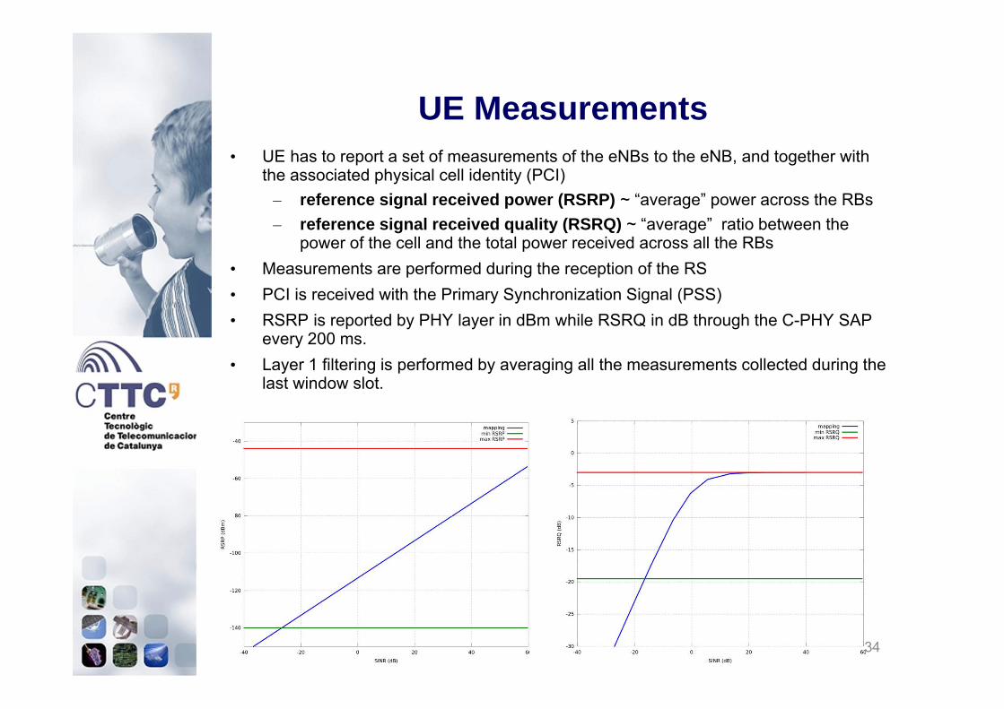
• UE has to report a set of measurements of the eNBs to the eNB, and together with the associated physical cell identity (PCI)
– reference signal received power (RSRP) ~ “average” power across the RBs– reference signal received quality (RSRQ) ~ “average” ratio between the
power of the cell and the total power received across all the RBs• Measurements are performed during the reception of the RS• PCI is received with the Primary Synchronization Signal (PSS)• RSRP is reported by PHY layer in dBm while RSRQ in dB through the C-PHY SAP
every 200 ms.• Layer 1 filtering is performed by averaging all the measurements collected during the
last window slot.
UE Measurements
34
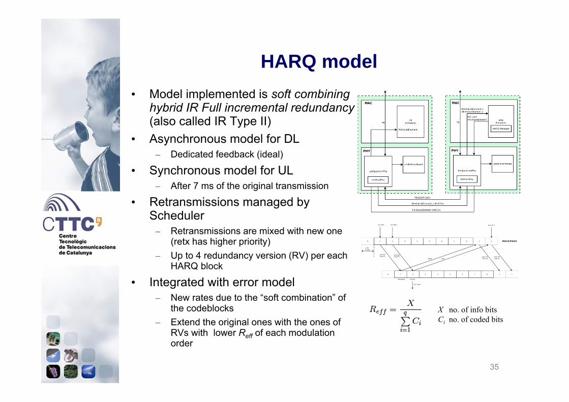
• Model implemented is soft combining hybrid IR Full incremental redundancy(also called IR Type II)
• Asynchronous model for DL– Dedicated feedback (ideal)
• Synchronous model for UL– After 7 ms of the original transmission
• Retransmissions managed by Scheduler
– Retransmissions are mixed with new one (retx has higher priority)
– Up to 4 redundancy version (RV) per each HARQ block
• Integrated with error model – New rates due to the “soft combination” of
the codeblocks– Extend the original ones with the ones of
RVs with lower Reff of each modulation order
HARQ model
35
X no. of info bitsCi no. of coded bits
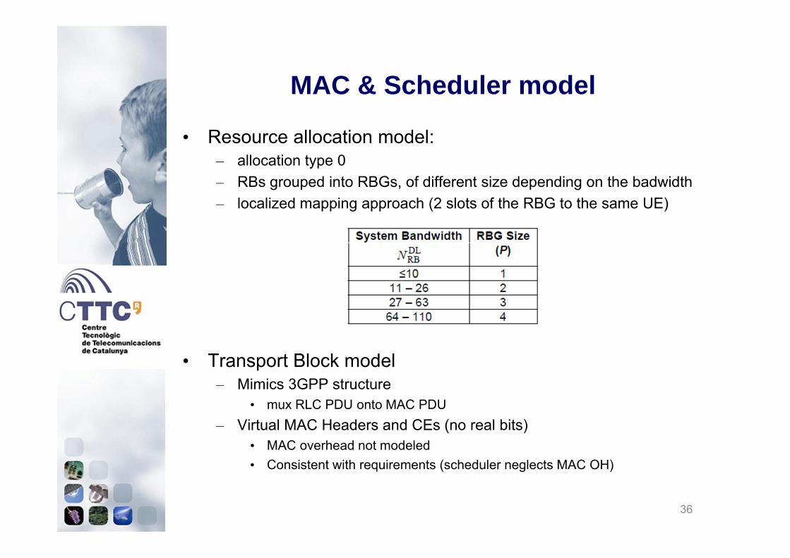
• Resource allocation model: – allocation type 0– RBs grouped into RBGs, of different size depending on the badwidth– localized mapping approach (2 slots of the RBG to the same UE)
• Transport Block model – Mimics 3GPP structure
• mux RLC PDU onto MAC PDU– Virtual MAC Headers and CEs (no real bits)
• MAC overhead not modeled• Consistent with requirements (scheduler neglects MAC OH)
MAC & Scheduler model
36
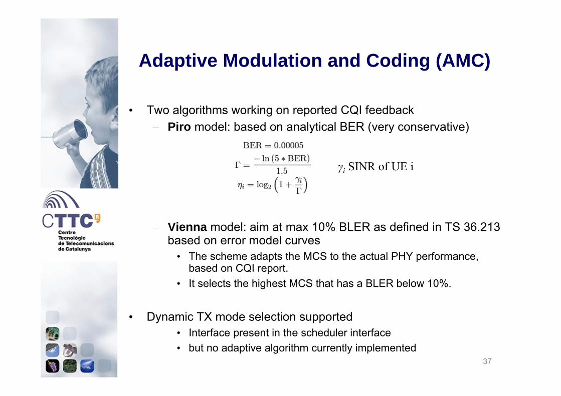
• Two algorithms working on reported CQI feedback– Piro model: based on analytical BER (very conservative)
– Vienna model: aim at max 10% BLER as defined in TS 36.213 based on error model curves
• The scheme adapts the MCS to the actual PHY performance, based on CQI report.
• It selects the highest MCS that has a BLER below 10%.
• Dynamic TX mode selection supported• Interface present in the scheduler interface• but no adaptive algorithm currently implemented
Adaptive Modulation and Coding (AMC)
37
γi SINR of UE i

• Round Robin (RR) • Proportional Fair (PF) • Maximum Throughput (MT) • Throughput to Average (TTA)• Blind Average Throughput (BET)• Token Bank Fair Queue (TBFQ)• Priority Set Scheduler (PSS)• Channel and QoS Aware Scheduler (CQA)
• B. Bojovic, N. Baldo, A new Channel and QoS Aware Scheduler to enhance the capacity of Voice over LTE systems , In Proceedings of 11th SSD, Feb 2014, Castelldefels (Spain)
• All implementations based on the FemtoForum API• The above algorithms are for downlink only• For uplink, all current implementations use the same Round Robin
algorithm• Assumption: HARQ has always higher priority wrt new data
MAC Scheduler implementations
LENA project
GSoC 2012
38

• Divide the available resources among the active UEs (i.e., the ones with at least one LC with buffer !=0)
• If no. of UEs > no. RBs– Circular buffer allocation
• The MCS for each user depends on the widebandCQI
Round Robin
39
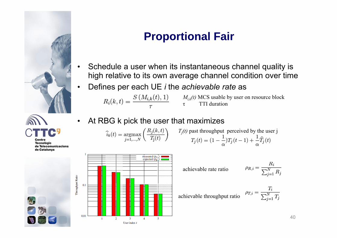
• Schedule a user when its instantaneous channel quality is high relative to its own average channel condition over time
• Defines per each UE i the achievable rate as
• At RBG k pick the user that maximizes
Proportional Fair
40
Mi,k(t) MCS usable by user on resource block τ TTI duration
Tj(t) past throughput perceived by the user j
achievable rate ratio
achievable throughput ratio

• Maximum Throughput (MT)
• Throughput to Average (TTA)
• Blind Average Throughput (BET)
• Token Bank Fair Queue (TBFQ)• leaky-bucket mechanism
• Priority Set Scheduler (PSS)• controls the fairness among UEs by a specified Target Bit Rate (TBR)
defined with QCI bearer primitive
GSoC 2012 Schedulers
41
Mi,k(t) MCS usable by user on resource block τ TTI duration
It aims at same throughput per all UEsTj(t) past throughput perceived by the user j
Calculated by subband CQI
It relates achievable throughput calculated per subband CQI vs wideband CQI
• Supported modes: – RLC TM, UM, AM as per 3GPP specs– RLC SM: simplified full-buffer model
• Features– PDUs and headers with real bits (following 3GPP specs)– Segmentation– Concatanation– Reassembly– SDU discard– Status PDU (AM only)– PDU retx (AM only)
• Unsupported features– Fragmentation of ReTx PDUs (resegmentation)
RLC Model
42

• Simplified model supporting the following:– Headers with real bytes following 3GPP specs– transfer of data (both user and control plane)– maintenance of PDCP SNs (sequence numbers)– transfer of SN status (for handover)
• Unsupported features– header compression and decompression using ROHC– in-sequence delivery of upper layer PDUs at re-establishment of lower layers– duplicate elimination of lower layer SDUs at re-establishment of lower layers for
radio bearers mapped on RLC AM– ciphering and deciphering of user plane data and control plane data– integrity protection and integrity verification of control plane data– timer based discard
PDCP model
43

• Initial cell selection– Cell search (based on RSRP of the received PSS)– Broadcast of system information (MIB, SIB1, SIB2)– Cell selection evaluation
• RRC Connection Establishment• RRC Connection Reconfiguration, supporting:
– SRB1 and DRB setup– SRS configuration index reconfiguration– PHY TX mode (MIMO) reconfiguration– Mobility Control Info (handover)
• UE Measurements– Event-based triggering supported (events A1 to A5)– Assumption: 1-to-1 PCI to EGCI mapping– Only E-UTRA intra-frequency; no measurement gaps
RRC Model features
44

• Random Access preamble transmission– Ideal model: no propagation / error model– Collisions modeled with protocol interference model– No capture effect contention resolution not modeled
• Random Access Response (RAR) – ideal message, no error model– In real system is a special PDU sent on DL-SCH– resource consumption can be modeled by enhanced
scheduler• Message3 – RRC connection request
– UL grant allocated by Scheduler – RLC TM PDU with actual bytes, subject to error model
• Contention resolution is not modeled• Supported modes:
– Contention based (for connection establishment)– Non-contention based (for handover)
Random Access model
45

• LteUeRrc: UE RRC logic• LteEnbRrc + UeManager: eNB RRC logic• Two models for RRC messages
– Ideal RRC• SRBs not used, no resources consumed, no errors
– Real RRC• actual RRC PDUs transmitted over SRBs• with ASN.1 encoding
RRC Model architecture
46
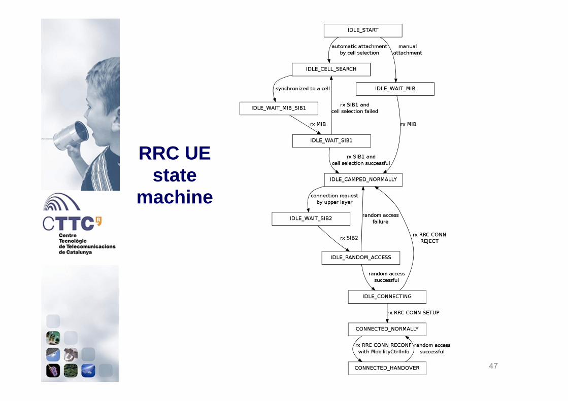
RRC UE state
machine
47

48
RRC eNB State Machine

• API for Handover Algorithms (GSoC 2013)– Measurement configuration– Measurement report handling– Handover triggering
• Available handover algorithms:– No-op– A2-A4-RSRQ– Strongest cell handover (A3-based)– <your algorithm here>
Handover Support
49

Handover example scenario
50
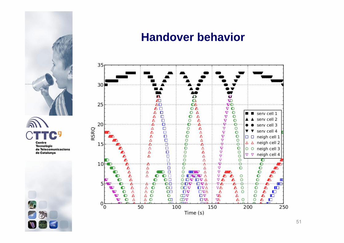
Handover behavior
51
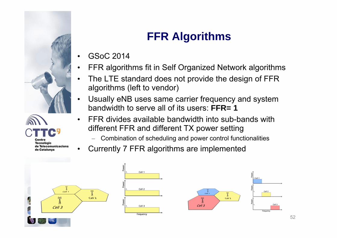
• GSoC 2014• FFR algorithms fit in Self Organized Network algorithms• The LTE standard does not provide the design of FFR
algorithms (left to vendor)• Usually eNB uses same carrier frequency and system
bandwidth to serve all of its users: FFR= 1• FFR divides available bandwidth into sub-bands with
different FFR and different TX power setting– Combination of scheduling and power control functionalities
• Currently 7 FFR algorithms are implemented
FFR Algorithms
52

• Full Frequency Reuse (no-op)• Hard Frequency Reuse• Strict Frequency Reuse• Soft Frequency Reuse (two versions)• Soft Fractional Frequency Reuse• Enhanced Fractional Frequency Reuse• Distributed Frequency Reuse Scheme
• More info:– P. Gawłowicz, N. Baldo, M. Miozzo, “An Extension of the ns-3 LTE Module to
Simulate Fractional Frequency Reuse Algorithms” , in Proceedings of Workshop on ns-3 (WNS3 2015), 13 May 2015, Barcelona (Spain).
FFR Algorithms
53
Carrier Aggregation
• Funded and initiated through GSoC2015• Component Carriers are divided in:
– 1 Primary Component Carrier (PCC)– Several Secondary Component Carriers (SCCs)
• The SCCs include the legacy LTE stack from MAC to PHY layer
• SCCs can be created only in LTE bands• Schedulers works in a total autonomous fashion
– Each CC has its own system information (e.g., DCIs, CQIs, etc.)
• LteEnbComponentCarrierManager is in charge of dispatching data among CCs:– Only PCC is working in the current implementation– Load balancing procedures among CCs can be
implemented

Control Plane

Data Plane

Flow of information

LENA model overview
58

• It is a protocol which allows UE to talk to MME• Focus on NAS Active state
– EMM (EPS Mobility management) Registered, ECM (EPS connection management) connected, RRC connected
• Logical interaction with MME– NAS PDUs not implemented
• Functionality– UE Attachment (transition to NAS Active state)– EPS Bearer activation– Multiplexing of data onto active EPS Bearers
• Based on Traffic Flow Templates• Both UDP and TCP over IPv4 are supported
• Unsupported features– PLMN and CSG selection– Idle mode (tracking area update, paging…)
NAS model
59

• S1-U (user data plane)– Realistic model including GTP-U implementation– Data packets forwarded over GTP/UDP/IPv4– Communication over ns3::PointToPoint links
• S1-C (control plane)– abstract model, no PDUs exchanged– Supported S1-AP primitives:
• INITIAL UE MESSAGE• INITIAL CONTEXT SETUP REQUEST• INITIAL CONTEXT SETUP RESPONSE• PATH SWITCH REQUEST• PATH SWITCH REQUEST ACKNOWLEDGE
S1 interface model
60

• X2-U (data plane) – GTP/UDP/IPv4 over ns3::PointToPoint (similar to S1-U)
• X2-C (control plane)– Hybrid model– Messages as PDUs over ns3::PointToPoint links– Enconded with no standard formats– Handover primitives:
• HANDOVER REQUEST• HANDOVER REQUEST ACK• HANDOVER PREPARATION FAILURE• SN STATUS STRANSFER• UE CONTEXT RELEASE
– SON primitives:• LOAD INFORMATION• RESOURCE STATUS UPDATE
X2 interface model
61

• abstract model– no GTP-C PDUs exchanged between MME and SGW
• Supported primitives:– CREATE SESSION REQUEST– CREATE SESSION RESPONSE– MODIFY BEARER REQUEST– MODIFY BEARER RESPONSE
S11 interface model
62

• Done via ns-3 attribute system• Several configurable attributes per LTE object• Default attribute values can be configured:
– Via input config file– Via command line– within simulation program
• Per-instance attribute values can be configured:– Within simulation program– Using GtkConfigStore
Simulation Configuration
63

• Lots of KPIs available at different levels:– Channel
• SINR maps• pathloss matrices
– PHY• TB tx / rx traces• RSRP/RSRQ traces
– MAC• UL/DL scheduling traces
– RLC and PDCP• Time-averaged PDU tx / rx stats • RLC considers only MAC delay, PDCP also RLC queues one
– IP and application stats• Can be obtained with usual ns-3 means• FlowMonitor, PCAP traces, get stats directly from app, etc.
Simulation Ouput
64
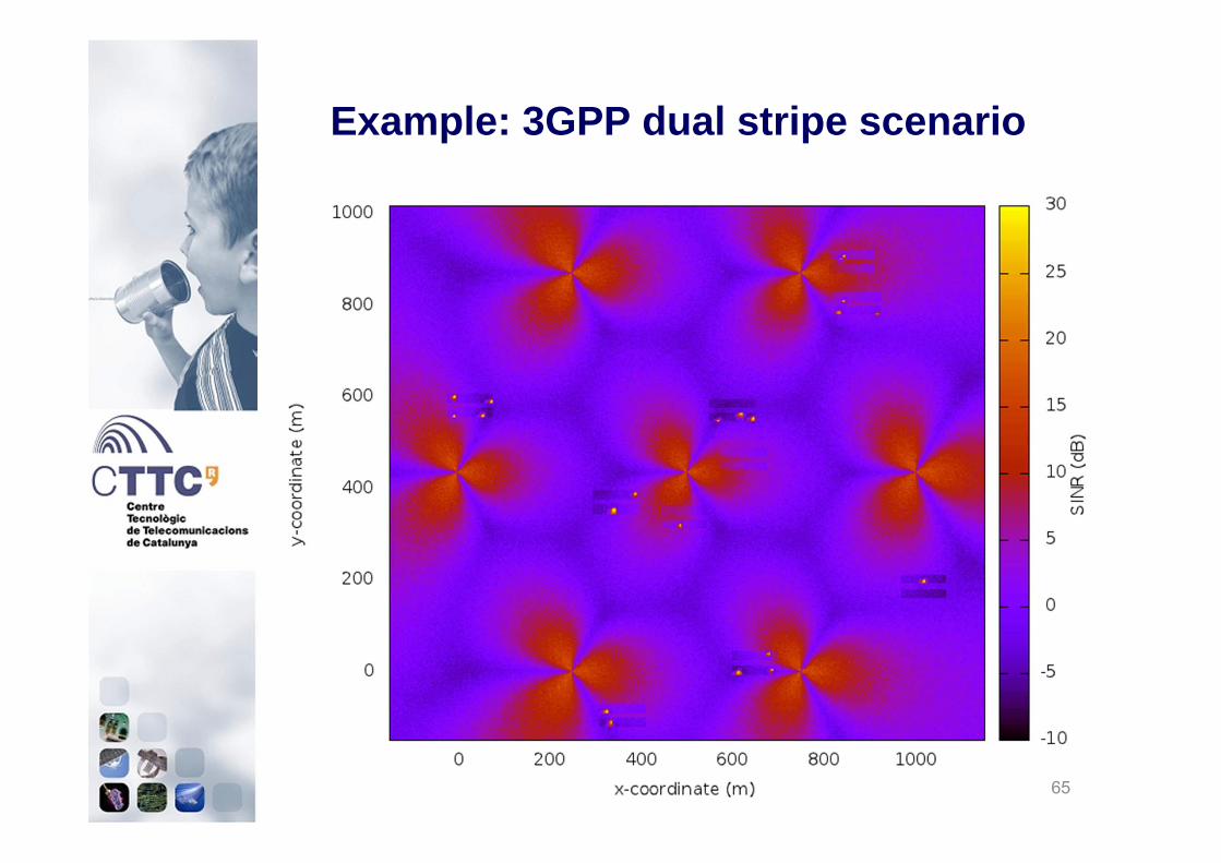
Example: 3GPP dual stripe scenario
65

Example: 3GPP dual stripe scenario
66
NOTES: • points are modelled as nodes• SINR is evaluated considering the strongest signal as the one of the
serving eNB

• Huge effort in testing:– Unit tests
• Checking that a specific module works properly– System test
• Checking that the whole LTE model works properly– Validation tests
• Validating simulation output against theoretical performance in a set of known cases
– Valgrind test coverage• Systematically check for memory errors
– memory corruption, leaks, etc. due to programming errors– Build tests
• Provided by ns-3 project for stable LENA code• Verify correct build on all supported plaftorms• LENA dev code tested daily on ubuntu
Testing
67

LTE module documentation• Part of the ns-3 models library docs• https://www.nsnam.org/docs/models/html/lte.html
Documentation
68