Embed Size (px)
Citation preview
Seattle City Light
MATERIAL STANDARD
Standard Number:
Superseding: Effective Date:
Page:
4240.00 April 6, 2017 September 7, 2017 1 of 12
Standards Coordinator Brett Hanson
Standards Supervisor John Shipek
Unit Director Darnell Cola
Pad Mounted, Three-Phase, Natural Ester Fluid Distribution Transformers
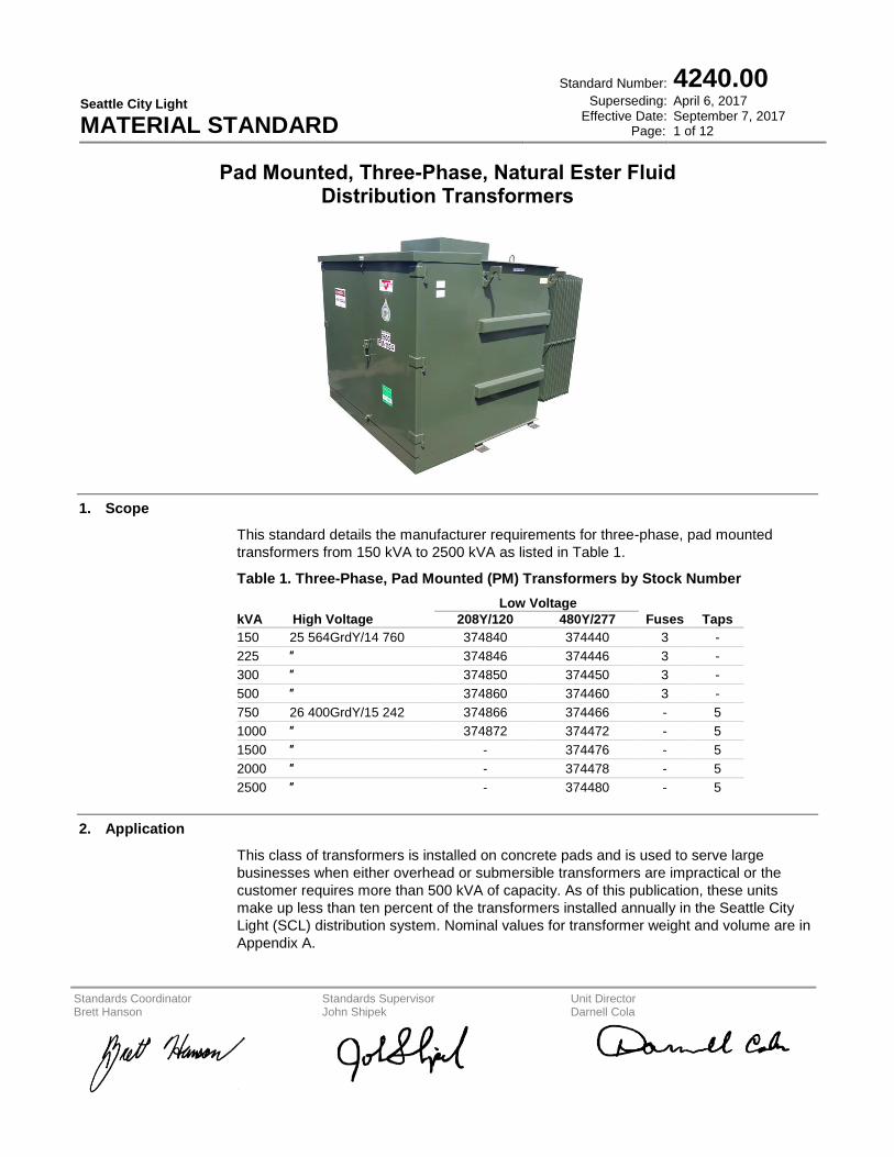
1. Scope
This standard details the manufacturer requirements for three-phase, pad mounted
transformers from 150 kVA to 2500 kVA as listed in Table 1.
Table 1. Three-Phase, Pad Mounted (PM) Transformers by Stock Number
kVA High Voltage
Low Voltage
Fuses Taps 208Y/120 480Y/277
150 25 564GrdY/14 760 374840 374440 3 -
225 ″ 374846 374446 3 -
300 ″ 374850 374450 3 -
500 ″ 374860 374460 3 -
750 26 400GrdY/15 242 374866 374466 - 5
1000 ″ 374872 374472 - 5
1500 ″ - 374476 - 5
2000 ″ - 374478 - 5
2500 ″ - 374480 - 5
2. Application
This class of transformers is installed on concrete pads and is used to serve large
businesses when either overhead or submersible transformers are impractical or the
customer requires more than 500 kVA of capacity. As of this publication, these units
make up less than ten percent of the transformers installed annually in the Seattle City
Light (SCL) distribution system. Nominal values for transformer weight and volume are in
Appendix A.
Seattle City Light MATERIAL STANDARD
Pad Mounted, Three-Phase, Natural Ester Fluid Distribution Transformers
Standard Number:
Superseding: Effective Date:
Page:
4240.00 April 6, 2017 September 7, 2017 2 of 12
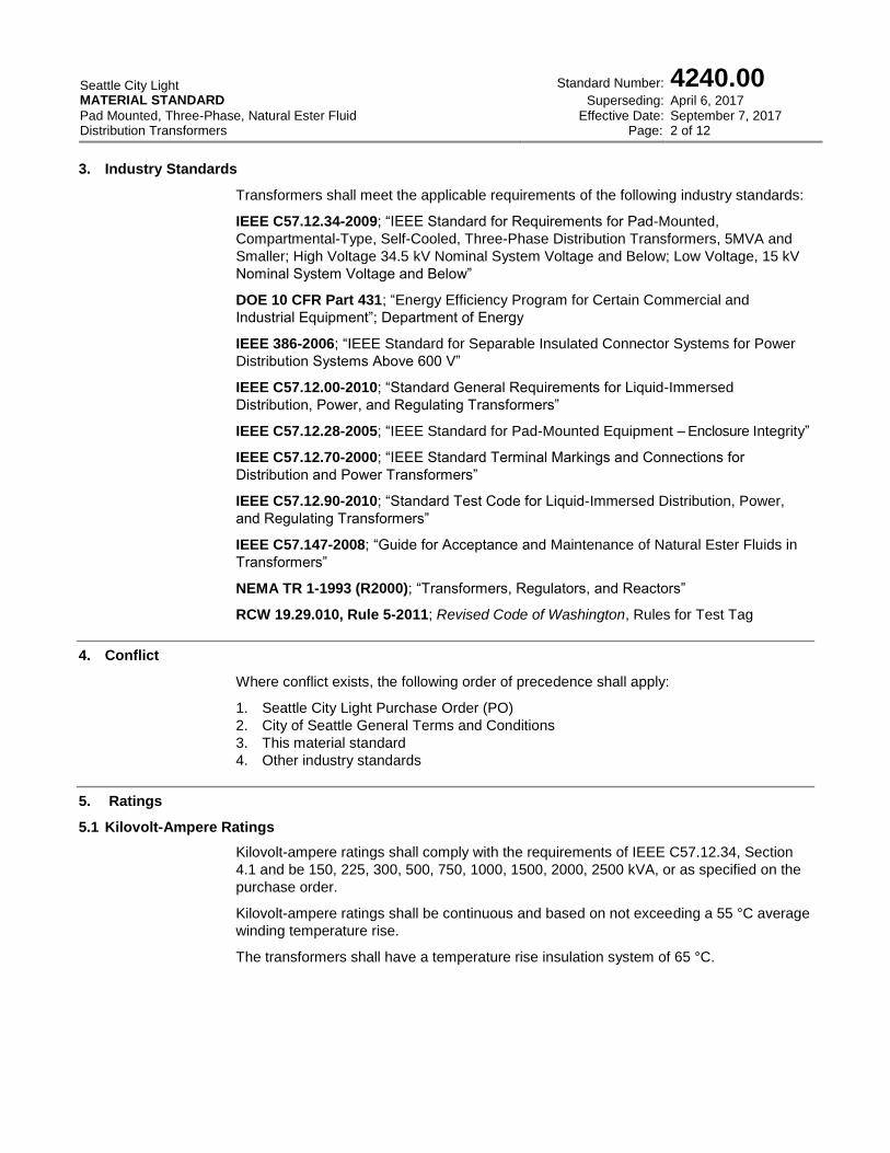
3. Industry Standards
Transformers shall meet the applicable requirements of the following industry standards:
IEEE C57.12.34-2009; “IEEE Standard for Requirements for Pad-Mounted,
Compartmental-Type, Self-Cooled, Three-Phase Distribution Transformers, 5MVA and
Smaller; High Voltage 34.5 kV Nominal System Voltage and Below; Low Voltage, 15 kV
Nominal System Voltage and Below”
DOE 10 CFR Part 431; “Energy Efficiency Program for Certain Commercial and
Industrial Equipment”; Department of Energy
IEEE 386-2006; “IEEE Standard for Separable Insulated Connector Systems for Power
Distribution Systems Above 600 V”
IEEE C57.12.00-2010; “Standard General Requirements for Liquid-Immersed
Distribution, Power, and Regulating Transformers”
IEEE C57.12.28-2005; “IEEE Standard for Pad-Mounted Equipment – Enclosure Integrity”
IEEE C57.12.70-2000; “IEEE Standard Terminal Markings and Connections for
Distribution and Power Transformers”
IEEE C57.12.90-2010; “Standard Test Code for Liquid-Immersed Distribution, Power,
and Regulating Transformers”
IEEE C57.147-2008; “Guide for Acceptance and Maintenance of Natural Ester Fluids in
Transformers”
NEMA TR 1-1993 (R2000); “Transformers, Regulators, and Reactors”
RCW 19.29.010, Rule 5-2011; Revised Code of Washington, Rules for Test Tag
4. Conflict
Where conflict exists, the following order of precedence shall apply:
1. Seattle City Light Purchase Order (PO)
2. City of Seattle General Terms and Conditions
3. This material standard
4. Other industry standards
5. Ratings
5.1 Kilovolt-Ampere Ratings
Kilovolt-ampere ratings shall comply with the requirements of IEEE C57.12.34, Section
4.1 and be 150, 225, 300, 500, 750, 1000, 1500, 2000, 2500 kVA, or as specified on the
purchase order.
Kilovolt-ampere ratings shall be continuous and based on not exceeding a 55 °C average
winding temperature rise.
The transformers shall have a temperature rise insulation system of 65 °C.
Seattle City Light MATERIAL STANDARD
Pad Mounted, Three-Phase, Natural Ester Fluid Distribution Transformers
Standard Number:
Superseding: Effective Date:
Page:
4240.00 April 6, 2017 September 7, 2017 3 of 12
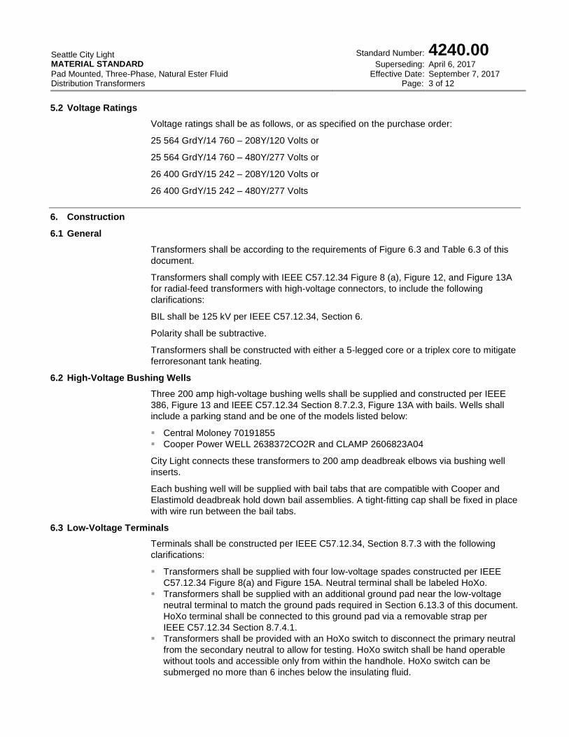
5.2 Voltage Ratings
Voltage ratings shall be as follows, or as specified on the purchase order:
25 564 GrdY/14 760 – 208Y/120 Volts or
25 564 GrdY/14 760 – 480Y/277 Volts or
26 400 GrdY/15 242 – 208Y/120 Volts or
26 400 GrdY/15 242 – 480Y/277 Volts
6. Construction
6.1 General
Transformers shall be according to the requirements of Figure 6.3 and Table 6.3 of this
document.
Transformers shall comply with IEEE C57.12.34 Figure 8 (a), Figure 12, and Figure 13A
for radial-feed transformers with high-voltage connectors, to include the following
clarifications:
BIL shall be 125 kV per IEEE C57.12.34, Section 6.
Polarity shall be subtractive.
Transformers shall be constructed with either a 5-legged core or a triplex core to mitigate
ferroresonant tank heating.
6.2 High-Voltage Bushing Wells
Three 200 amp high-voltage bushing wells shall be supplied and constructed per IEEE
386, Figure 13 and IEEE C57.12.34 Section 8.7.2.3, Figure 13A with bails. Wells shall
include a parking stand and be one of the models listed below:
Central Moloney 70191855
Cooper Power WELL 2638372CO2R and CLAMP 2606823A04
City Light connects these transformers to 200 amp deadbreak elbows via bushing well
inserts.
Each bushing well will be supplied with bail tabs that are compatible with Cooper and
Elastimold deadbreak hold down bail assemblies. A tight-fitting cap shall be fixed in place
with wire run between the bail tabs.
6.3 Low-Voltage Terminals
Terminals shall be constructed per IEEE C57.12.34, Section 8.7.3 with the following
clarifications:
Transformers shall be supplied with four low-voltage spades constructed per IEEE
C57.12.34 Figure 8(a) and Figure 15A. Neutral terminal shall be labeled HoXo.
Transformers shall be supplied with an additional ground pad near the low-voltage
neutral terminal to match the ground pads required in Section 6.13.3 of this document.
HoXo terminal shall be connected to this ground pad via a removable strap per
IEEE C57.12.34 Section 8.7.4.1.
Transformers shall be provided with an HoXo switch to disconnect the primary neutral
from the secondary neutral to allow for testing. HoXo switch shall be hand operable
without tools and accessible only from within the handhole. HoXo switch can be
submerged no more than 6 inches below the insulating fluid.
Seattle City Light MATERIAL STANDARD
Pad Mounted, Three-Phase, Natural Ester Fluid Distribution Transformers
Standard Number:
Superseding: Effective Date:
Page:
4240.00 April 6, 2017 September 7, 2017 4 of 12
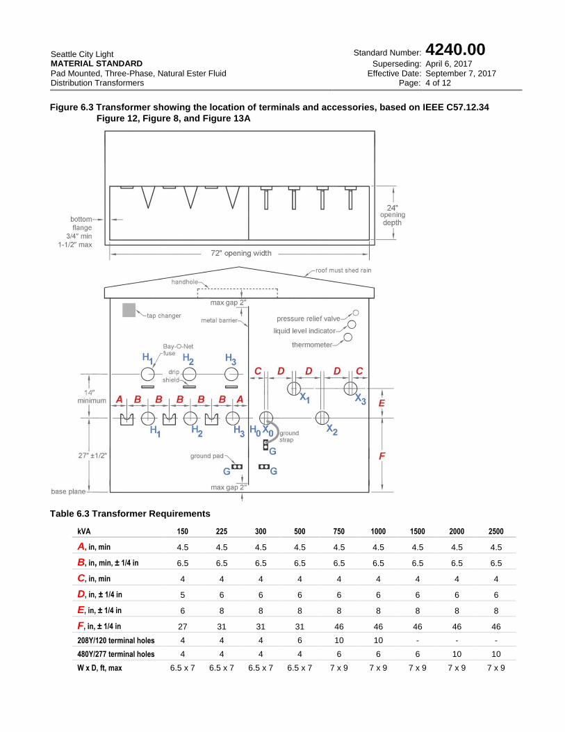
Figure 6.3 Transformer showing the location of terminals and accessories, based on IEEE C57.12.34
Figure 12, Figure 8, and Figure 13A
Table 6.3 Transformer Requirements
kVA 150 225 300 500 750 1000 1500 2000 2500
A, in, min 4.5 4.5 4.5 4.5 4.5 4.5 4.5 4.5 4.5
B, in, min, ± 1/4 in 6.5 6.5 6.5 6.5 6.5 6.5 6.5 6.5 6.5
C, in, min 4 4 4 4 4 4 4 4 4
D, in, ± 1/4 in 5 6 6 6 6 6 6 6 6
E, in, ± 1/4 in 6 8 8 8 8 8 8 8 8
F, in, ± 1/4 in 27 31 31 31 46 46 46 46 46
208Y/120 terminal holes 4 4 4 6 10 10 - - -
480Y/277 terminal holes 4 4 4 4 6 6 6 10 10
W x D, ft, max 6.5 x 7 6.5 x 7 6.5 x 7 6.5 x 7 7 x 9 7 x 9 7 x 9 7 x 9 7 x 9
Seattle City Light MATERIAL STANDARD
Pad Mounted, Three-Phase, Natural Ester Fluid Distribution Transformers
Standard Number:
Superseding: Effective Date:
Page:
4240.00 April 6, 2017 September 7, 2017 5 of 12
6.4 Taps
For transformers rated 750 kVA or more, a full-capacity de-energized tap changer shall
be supplied and located per Figure 6.3 of this document. Taps shall comply with
C57.12.34 Section 4.3 except the nominal voltage shall be 26400 volts and there will be
one tap above and three below. Tap voltages shall be 27060, 26400, 25740, 25080, and
24420. Units shall be shipped on the 25740-volt tap.
6.5 Overcurrent Protection
For transformers rated 500 kVA or less overcurrent protection shall be a Bay-O-Net fuse
assembly installed and furnished with a dual sensing fuse as listed below. Isolation links
shall not be installed because each transformer is protected upstream by a backup
current limiting fuse. A drip shield shall be provided on each unit.
Bay-O-Net Fuse Assembly
Cooper Power Systems 4000361C99MC
Dual-Sensing Bay-O-Net Fuse
Transformer, kVA Cooper Power Systems Catalog No amps
150 4000358C08 15
225 4000358C08 15
300 4000358C08 15
500 4000358C10 25
6.6 Liquid Level Marking
Liquid level indication shall be provided for every unit. See IEEE C57.12.34, Section
8.10.2.
For transformers rated 750 kVA or more, provide a liquid level gauge and temperature
gauge in the low-voltage compartment. Liquid level gauge shall include an indication of
the correct liquid level at 25 °C. Temperature gauge shall be a resettable dial-type
thermometer with needles indicating the current top of oil temperature and the highest
temperature recorded since last reset.
6.7 Lifting Provisions
Lifting provisions shall be provided per IEEE C57.12.34, Section 8.6.
6.8 Pressure Relief Valve
A pressure relief valve shall be provided per SCL 4503.10 and IEEE C57.12.34,
Section 8.9.2 with the following clarifications:
6.8.1 Indicator
The pressure relief valve shall include an orange or red indicator that becomes visible
only after the valve has vented.
Seattle City Light MATERIAL STANDARD
Pad Mounted, Three-Phase, Natural Ester Fluid Distribution Transformers
Standard Number:
Superseding: Effective Date:
Page:
4240.00 April 6, 2017 September 7, 2017 6 of 12
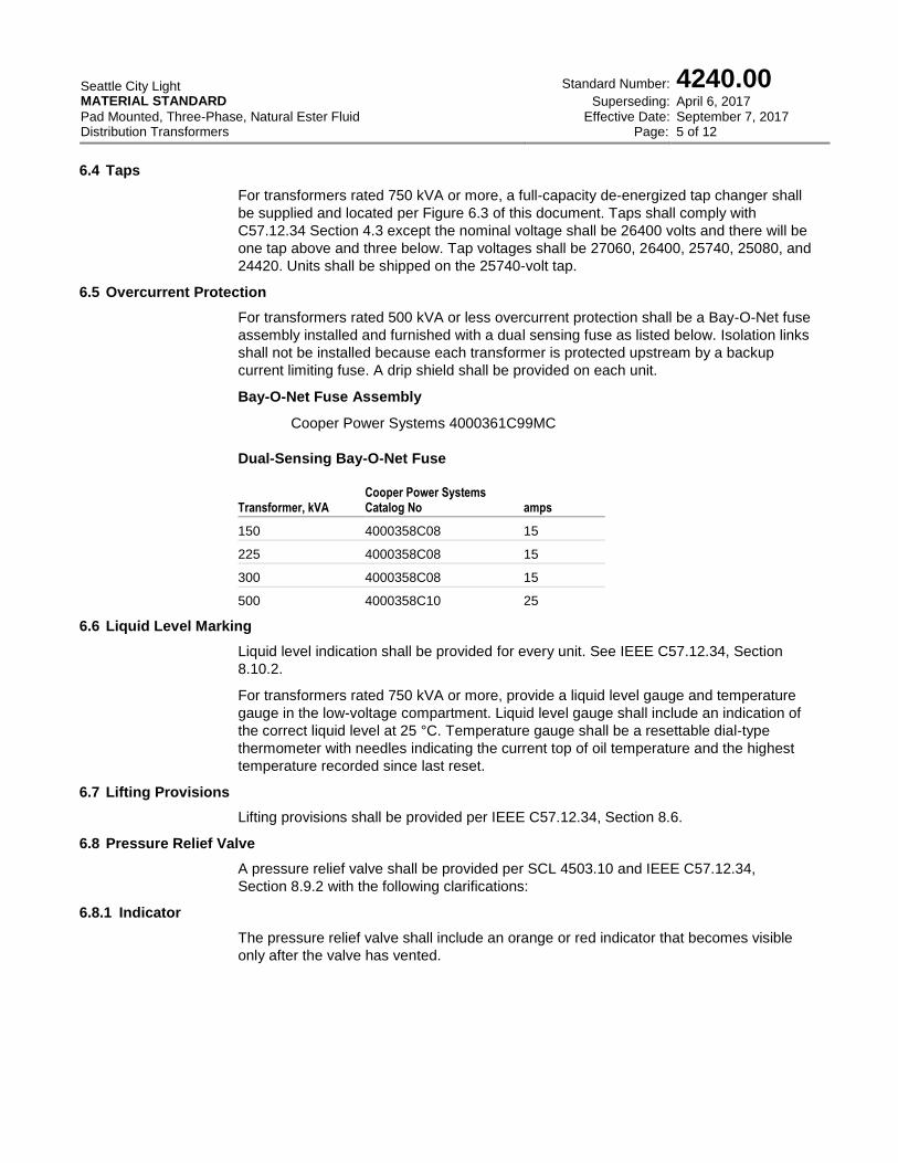
Figure 6.8.1 Pressure Relief Valve
6.8.2 Cap and Pull Ring
The valve shall be covered by a cap with a pull ring. The cap will separate from the
assembly during venting, revealing the orange or red indicator and will hang down from
the valve via a chain or strap.
6.8.3 Sealant
Valve threads shall be sealed with a liquid pipe thread compound such as Rectorseal,
liquid Teflon, or similar, not Teflon tape.
6.8.4 Approved Models
The pressure relief valve shall be listed for use with the included transformer fluid and be
one of the models listed in SCL 4503.10.
6.8.5 Location
The valve shall be installed in the low-voltage portion of the terminating compartment as
shown in Figure 6.3.
6.9 Enclosure Integrity
The completely assembled transformer enclosure shall comply with IEEE C57.12.28.
Terminal compartment shall be constructed per IEEE C57.12.34 Sections 8.1, 8.2, 8.3,
8.4, and 8.5.
Enclosure roof shall shed rain and prevent collection of water.
6.10 Polarity, Terminal Markings, and Angular Displacement
Polarity, terminal markings, and angular displacement shall be according to the
requirements of IEEE C57.12.34, Section 8.7.
Primary terminals, secondary terminals, and ground lugs shall be marked with minimum
1-inch tall letters.
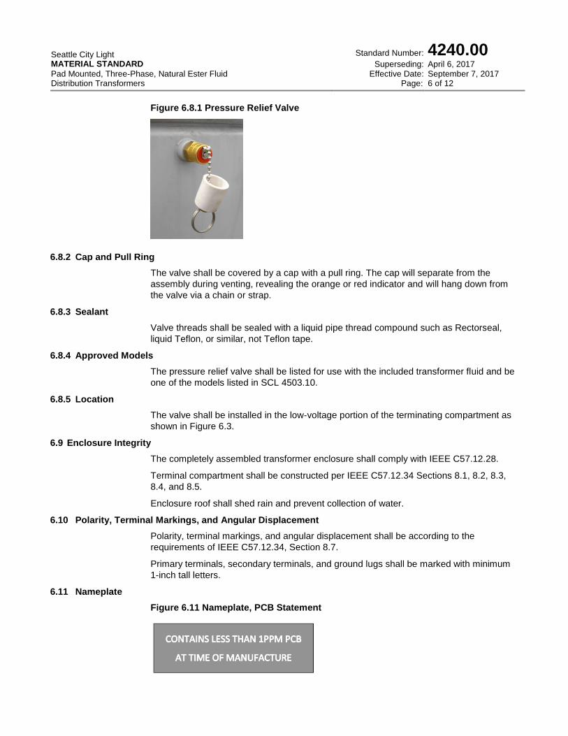
6.11 Nameplate
Figure 6.11 Nameplate, PCB Statement
Seattle City Light MATERIAL STANDARD
Pad Mounted, Three-Phase, Natural Ester Fluid Distribution Transformers
Standard Number:
Superseding: Effective Date:
Page:
4240.00 April 6, 2017 September 7, 2017 7 of 12
Nameplate shall be according to the requirements of IEEE C57.12.34, Section 8.8 and
IEEE C57.12.00, Section 5.12 (Nameplate C for all kVA ratings) with the following
clarifications:
Class shall be KNAN.
BIL shall be 125 kV.
Tested impedance shall be listed.
Tested X/R ratio shall be listed.
Total weight in pounds shall be indicated for each individual transformer.
Volume in gallons of insulating fluid shall be indicated.
Manufacturer name and part number of the Bay-o-Net fuse assembly shall be
indicated.
Manufacturer name and part number of the dual sensing fuse shall be indicated.
Tank design pressures shall be listed to comply with Section 6.13.4 of this document.
HoXo switch shall be shown in the phasor diagram.
The statement “CONTAINS LESS THAN 1PPM PCB AT TIME OF MANUFACTURE.”
shall appear on the nameplate.
6.12 Fluid
Natural ester insulating fluid complying with IEEE C57.147 shall be provided in the
transformer up to the liquid level marking.
Fluid shall be Cooper Envirotemp FR3. Each transformer shall have a minimum 5-inch
diameter label indicating fluid brand.
6.13 Tank
Tank shall meet all the integrity requirements of IEEE C57.12.34, Section 8.10.
6.13.1 Cover
Cover shall comply with IEEE C57.12.28.
Cover shall be welded to the tank.
6.13.2 Tank Finish
Tank finish shall comply with IEEE C57.12.28, Section 5. The tank finish color shall be
Semi Gloss Dark Green Munsell Notation 7GY 3.29/1.5.
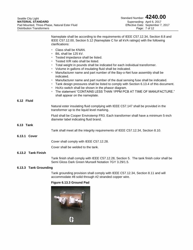
6.13.3 Tank Grounding
Tank grounding provision shall comply with IEEE C57.12.34, Section 8.11 and will
accommodate #8 solid through #2 stranded copper wire.
Figure 6.13.3 Ground Pad

Seattle City Light MATERIAL STANDARD
Pad Mounted, Three-Phase, Natural Ester Fluid Distribution Transformers
Standard Number:
Superseding: Effective Date:
Page:
4240.00 April 6, 2017 September 7, 2017 8 of 12
6.13.4 Strength
Tank will be designed to withstand negative and positive 7 psig per IEEE C57.12.34
Section 8.10.1.
6.13.5 Handhole
Tank shall include a handhole to access internal components for testing. The handhole
shall have a cover that can be unbolted from within the terminal compartments to prevent
unauthorized access. The handhole shall have a minimum opening of 121 square inches
and will provide access to the HoXo switch. The gasket shall be one-piece material.
6.13.6 Drain Valve
A one-inch globe-type drain valve shall be installed, including a 3/8-inch sampling device
and a plug. The valve shall be installed on a pipe nipple welded to the tank in the primary
section of the terminal compartment.
Figure 6.13.6 Drain Valve
7. Tests
7.1 General
All applicable tests shall be performed as specified in IEEE C57.12.00 and in IEEE
C57.12.90.
7.2 Dielectric Tests
Dielectric tests shall be performed as specified in IEEE C57.12.34, Section 7.2 and IEEE
C57.12.90, Section 10. Dielectric test levels shall be in accordance with the levels
specified in IEEE C57.12.00, Section 5.10.
7.3 Tank and Enclosure Tests
Tests shall be performed as specified in IEEE C57.12.34, Section 8.10.1 and
IEEE C57.12.28.
7.4 Short Circuit Tests
Short circuit tests shall be performed as specified in IEEE C57.12.90, Section 12.
7.5 Audible Sound Levels
Audible sound levels for each unit shall be according to the requirements of
NEMA TR-1, Section 0.05. Tests shall be performed per IEEE C57.12.90, Section 13.
7.6 Radio Influence Voltage Test
Radio influence voltage shall be according to the requirements of NEMA TR-1,
Section 0.03.
Seattle City Light MATERIAL STANDARD
Pad Mounted, Three-Phase, Natural Ester Fluid Distribution Transformers
Standard Number:
Superseding: Effective Date:
Page:
4240.00 April 6, 2017 September 7, 2017 9 of 12
7.7 Load and No-Load Tests
Load and no-load loss measurements shall be performed at 85 degrees C and 20
degrees C, respectively, according to the requirements of IEEE C57.12.00, Section 5.9
and shall comply with IEEE C57.12.90.
7.8 Documentation
Tests reports demonstrating conformance to all tests completed shall be submitted in a
single electronic document. All documentation shall be in English and use customary
inch-pound units.
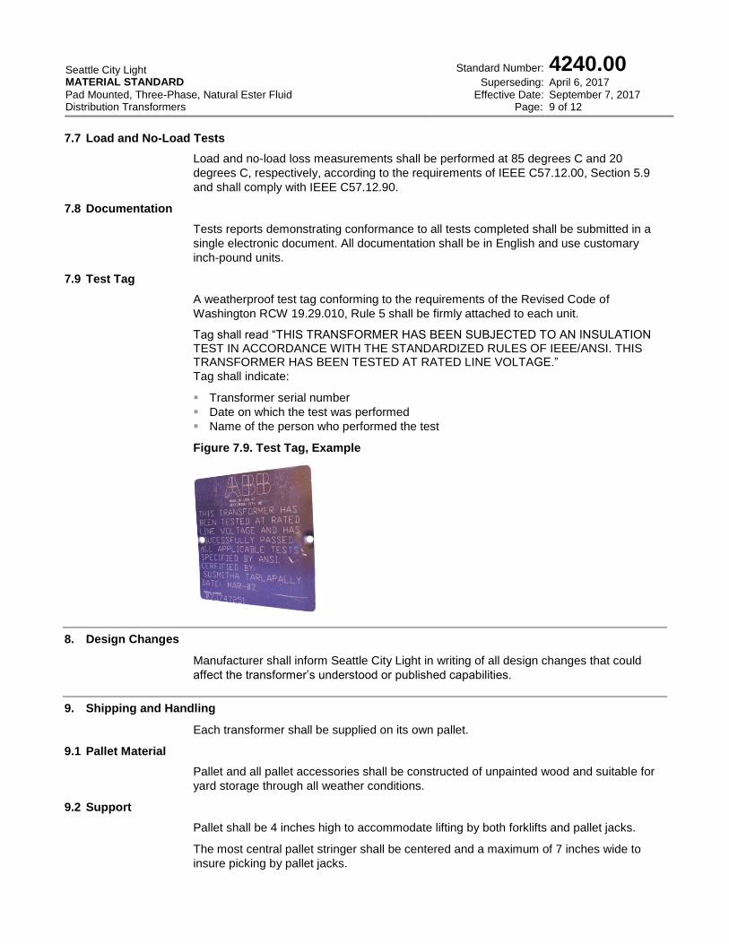
7.9 Test Tag
A weatherproof test tag conforming to the requirements of the Revised Code of
Washington RCW 19.29.010, Rule 5 shall be firmly attached to each unit.
Tag shall read “THIS TRANSFORMER HAS BEEN SUBJECTED TO AN INSULATION TEST IN ACCORDANCE WITH THE STANDARDIZED RULES OF IEEE/ANSI. THIS TRANSFORMER HAS BEEN TESTED AT RATED LINE VOLTAGE.”
Tag shall indicate:
Transformer serial number
Date on which the test was performed
Name of the person who performed the test
Figure 7.9. Test Tag, Example
8. Design Changes
Manufacturer shall inform Seattle City Light in writing of all design changes that could
affect the transformer’s understood or published capabilities.
9. Shipping and Handling
Each transformer shall be supplied on its own pallet.
9.1 Pallet Material
Pallet and all pallet accessories shall be constructed of unpainted wood and suitable for
yard storage through all weather conditions.
9.2 Support
Pallet shall be 4 inches high to accommodate lifting by both forklifts and pallet jacks.
The most central pallet stringer shall be centered and a maximum of 7 inches wide to
insure picking by pallet jacks.
Seattle City Light MATERIAL STANDARD
Pad Mounted, Three-Phase, Natural Ester Fluid Distribution Transformers
Standard Number:
Superseding: Effective Date:
Page:
4240.00 April 6, 2017 September 7, 2017 10 of 12
9.3 Orientation
Transformer shall be centered on pallet and secured via its pad attachments.
Transformer shall be oriented on the pallet to prevent transformer enclosure from coming
into contact with pallet moving equipment or otherwise shall be enclosed by protective
devices to prevent damage.
9.4 Arrival Condition
Transformers shall be delivered on covered or enclosed trucks.
Transformers shall be received by Seattle City Light in clean condition.
10. Seattle City Light Processes
10.1 Bid Process
Bid process details are available at www.seattle.gov.
Bid documentation shall be submitted with details demonstrating conformance to this
standard. Submittal details shall be listed to correspond with this standard’s section
formatting.
Any exceptions taken to the standard shall be summarized in an attached letter, complete
with section numbering relating to this standard. Requests for approved equal
components must be submitted with first bid documents; all subsequent requests will be
rejected.
10.2 Loss Factors
Load and no-load loss measurements shall be performed at 85°C and 20°C, respectively
according to the requirements of IEEE C57.12.00, Section 5.9 and shall comply with
IEEE C57.12.90.
10.2.1 Load Loss
Load losses shall be assessed at $2.60 per watt.
10.2.2 No-Load Loss
No-load “core” losses shall be assessed at $5.90 per watt.
10.2.3 Loss Assessment
Total Price ($) = Bid Price + Loss Total
Loss Total = Load Loss + No-load Loss
Load Loss = Losses (Watts) x $2.60
No-load Loss = Losses (Watts) x $5.90
The manufacturer will be assessed a penalty for transformers delivered that exceed the
total loss value stated and calculated on the bid proposal. The penalty shall be the
difference between the total loss values delivered less the total loss value in the bid
proposal.
Tolerances will be allowed in accordance with IEEE C57.12.90, Section 9.3, except,
tolerances shall apply to transformers of a given size and voltage; i.e., one line item.
Individual transformers that exceed these tolerances may be rejected and returned to the
manufacturer.
Seattle City Light MATERIAL STANDARD
Pad Mounted, Three-Phase, Natural Ester Fluid Distribution Transformers
Standard Number:
Superseding: Effective Date:
Page:
4240.00 April 6, 2017 September 7, 2017 11 of 12
10.3 Bid Completion
Upon completion of the bidding process, the successful bidder shall submit in a single
electronic file the following:
Transformer dimensions and spare parts list
Nameplate
Loss data
Instructional materials demonstrating the proper installation, operation, and
maintenance of the equipment.
Certified test data for each transformer type bid and for every category listed in
IEEE C57.12.00, Section 8.6. Format test data using numbering system shown in
IEEE C57.12.00, Section 8.6.
10.4 Inspection and Electrical Testing
Upon delivery, the transformers will be inspected for physical defects and conformance to
this standard.
The transformers will be tested electrically for Radio Influence Voltage (per NEMA TR-1,
Section 7 at 1MHz and 17.4kV, RIV not to exceed 100 microVolts), losses and a small
battery of other tests.
If any transformer fails, the manufacturer will be contacted and given the option to take
back the lot or take back the lot except the units that passed during initial testing.
10.5 Guarantee
Any transformer failing due to defective design, material, and/or workmanship within 12
months after being energized or 18 months after delivery, shall be repaired or replaced
without cost to the City of Seattle. Any defect discovered within this period shall be
corrected on all transformers furnished on the order at the manufacturer's expense, either
by repair or replacement.
11. Issuance
Stock Unit: EA
12. Approved Manufacturers and Factories
ABB Jefferson City Missouri
Carte International Winnipeg, Manitoba, Canada
Cooper Power Waukesha, Wisconsin
13. References
SCL Material Standard 4503.10; “Valve, Transformer Pressure Relief”
14. Sources
Hanson, Brett; SCL Standards Engineer and subject matter expert for 4240.00
SCL Material Standard 0028.3; “Distribution Transformer, Three-Phase, Padmount Type
75 through 500 kVA, No Taps, Natural Ester Fluid” (canceled)
SCL Material Standard 0028.5; “Distribution Transformer, Three-Phase, Padmount Type
750 through 2500 kVA, With Taps, Natural Ester Fluid” (canceled)
Seattle City Light MATERIAL STANDARD
Pad Mounted, Three-Phase, Natural Ester Fluid Distribution Transformers
Standard Number:
Superseding: Effective Date:
Page:
4240.00 April 6, 2017 September 7, 2017 12 of 12
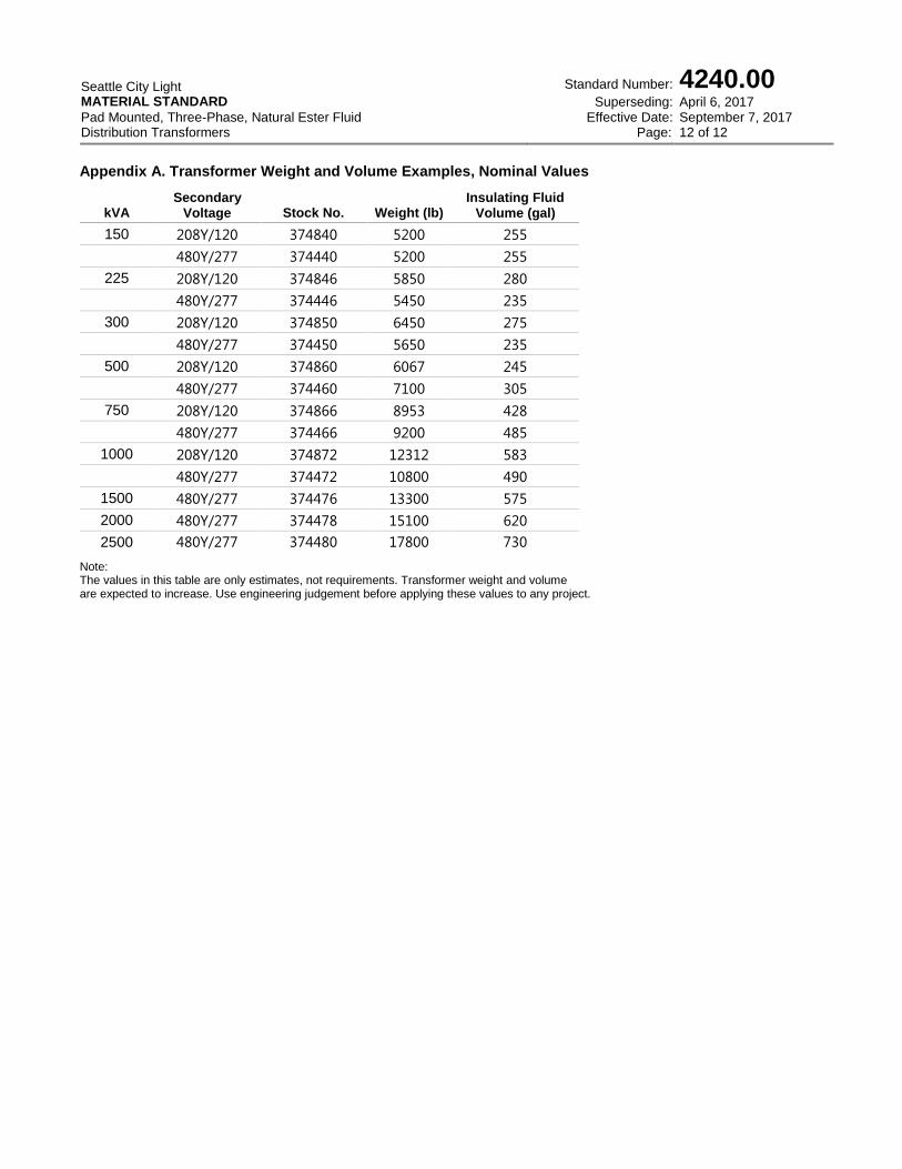
Appendix A. Transformer Weight and Volume Examples, Nominal Values
kVA Secondary
Voltage Stock No. Weight (lb) Insulating Fluid
Volume (gal)
150 208Y/120 374840 5200 255
480Y/277 374440 5200 255
225 208Y/120 374846 5850 280
480Y/277 374446 5450 235
300 208Y/120 374850 6450 275
480Y/277 374450 5650 235
500 208Y/120 374860 6067 245
480Y/277 374460 7100 305
750 208Y/120 374866 8953 428
480Y/277 374466 9200 485
1000 208Y/120 374872 12312 583
480Y/277 374472 10800 490
1500 480Y/277 374476 13300 575
2000 480Y/277 374478 15100 620
2500 480Y/277 374480 17800 730
Note: The values in this table are only estimates, not requirements. Transformer weight and volume are expected to increase. Use engineering judgement before applying these values to any project.