Embed Size (px)
DESCRIPTION
Utility Dist board
Citation preview

P.O. Box 716 • Postal Code 130 • Ghalah -Bousher • Muscat • Oman
Telephone +968 24 628 000• Fax +968 246 28 001
TEBODINConsultants & Engineers
[email protected] • www.tebodin.com • www.tebodinme.com f"·F'·..fo j .:Jj-.}
iJ.HJw.;;....l_, iJJ-
Client: Daleel Petroleum LLC Oman
EPC Contractor: Arabian Oil & Gasfield Services & Jaihind
Project: DD for Upgrade of WI and WT Facility
.-""'Daleel Petroleum ARABIAN OIL & GASFIELD SERVICES'"
UTILITY DISTRIBUTION BOARD
SPECIFICATION
Client Doc. No: DAL-4-4009-000-87-A4
Order number: 25145
Document number: 4183005
Revision: A
Author: Sachin Gore
Telephone: +968 246 28 000
Fax: +968 246 28 001
E-mail: [email protected]
Date: 29 April2013
Page 1 of 15
···· •·
l1TEBODINCo n sultan ts & Engineers
Tebodin & Partner LLC SpecificationOrder number: 25145
Document number: 4183005
Revision: A
Date: 29.04.2013
Page 2 of 15
Approved by: Daleel Petroleum Oman LLC A
Ahmed Aziz
Rev: Date
Approved by:
A
'Name I Ref.Jni:l ..
\. l /
A 29.04.13 Issue for Review MSK " VMA
I . '·... • •,,. ., i·· :·c. ..,
. -' · · • = ··_•••••• Authoriz itby I"Rev. Date Desct;ption. .
Author<. • c ecked b)l ,(\pproved·byTA :6 :: · ····.·_•.•:• •..'' ..' .. ::":.:.:...:::·.. ..... ·· .:::.:.-·
Copyright Tebodin & Partner LLC@
All rights reserved. No part of this publication may be reproduced or transmitted in any form or by any means without permission of the publisher.
eport title: Specification for Utilti y distribution board:\OTHER CLIENTS\25145 AROGAS DD For Upgrade Of WI And WT Facility\Project Archive\Temporary Archive\Dept 41 Electricai\Documents\4183005 Rev A LV UDB Specifci ation\4183005

Utility Distribution Board Specification.Docx

ll TEBODIN Consultants & Engineers
Tebodin & Partner LLC SpecificationOrder number: 25145
Document number: 4183005
Revision: A
Date: 29.04.2013 f"·f'·..;. J jo.}Page 3 of 14 l.)j--:!.) 1_, I.JJ-
Table of Content Page
1 INTRODUCTION ...................................................................................................................................... 4
1.1 GENERAL ............................................................................................................................ 41.2 DEFINITIONS....................................................................................................................... 4
2 CODES, SPECIFICATION AND STANDARDS ..................................................................................... 4
2.1 GENERAL ........................................................................................................................... .42.2 INTERNATIONAL STANDARDS ....................................................................................... .4
3 SCOPE OF SUPPLY ............................................................................................................................... 5
4 DESIGN & MANUFACTURING .............................................................................................................. 5
5 EARTHING ............................................................................................................................................... 7
6 PAINTING.................................................................:............................................................................... 7
7 NAME PLATE AND LABELS ................................................................................................................. 7
8 TYPE TESTS............................................................................................................................................ 8
9 ROUTINE TESTS..................................................................................................................................... 8
10 SPARE PARTS........................................................................................................................................ 9
11 DOCUMENTATION REQUIREMENTS .................................................................................................. 9
12 INFORMATION TO BE SUBMITTED ..................................................................................................... 9
13 DELIVERY................................................................................................................................................ 9
14 SUPPLIER'S RESPONSIBILITY .......................................................................................................... 10
15 WARRANTY........................................................................................................................................... 10
16 TABLE OF COMPLIANCE .................................................................................................................... 11
17 ATTACHMENTS .................................................................................................................................... 12
17.1 ATTACHMENT·1: UTILITY DISTRIBUITION BOARD DATA SCHEDULE ....................................... 13
17.2 ATTACHMENT-2: SINGLE LINE DIAGRAM OF 415V UTILITY DISTRIBUTION BOARDS ............ 14
";g . ti·t IEe : t; ; ;r;;i'". for Utllity distribution boardT:' 11 AROGAS-DD For Upgrade Of WI And WT Facility\Project Archive\Temporary Archive\Dept 41 E!ectricai\Oocuments\4183005-Rev A LV UDB Specification\4183005
Uti!ity Distribution Board Specification.Docx
TEBODINConsultants & Engineers
Tebodin & Partner LLC SpecificationOrder number: 25145
Document number: 4183005
Revision: A
Date: 29.04.2013
Page 4 of 14
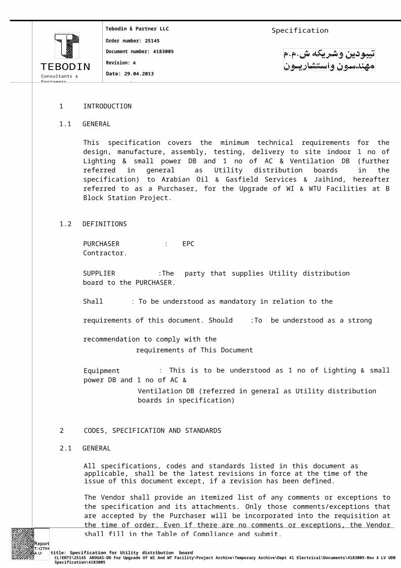
1 INTRODUCTION
1.1 GENERAL
This specification covers the minimum technical requirements for the design, manufacture, assembly, testing, delivery to site indoor 1 no of Lighting & small power DB and 1 no of AC & Ventilation DB (further referred in general as Utility distribution boards in the specification) to Arabian Oil & Gasfield Services & Jaihind, hereafter referred to as a Purchaser, for the Upgrade of WI & WTU Facilities at B Block Station Project.
1.2 DEFINITIONS
PURCHASER : EPC Contractor.
SUPPLIER :The party that supplies Utility distribution board to the PURCHASER.
Shall : To be understood as mandatory in relation to the requirements of this document.
Should :To be understood as a strong recommendation to comply with the
requirements of This Document
Equipment : This is to be understood as 1 no of Lighting & small power DB and 1 no of AC &
Ventilation DB (referred in general as Utility distribution boards in specification)
2 CODES, SPECIFICATION AND STANDARDS
2.1 GENERAL
All specifications, codes and standards listed in this document as applicable, shall be the latest revisions in force at the time of the issue of this document except, if a revision has been defined.
The Vendor shall provide an itemized list of any comments or exceptions to the specification and its attachments. Only those comments/exceptions that are accepted by the Purchaser will be incorporated into the requisition at the time of order. Even if there are no comments or exceptions, the Vendor shall fill in the Table of Compliance and submit.
2.2 INTERNATIONAL STANDARDS
IEC 61439 Low voltage Switchgear & control Assemblies IEC
60529 Degree of protection provided by enclosures (IP)
IEC 60947 Low voltage Switchgear & control gear
IEC 60044 Instrument transformers
IEC 60269 Low voltage fuses. General requirements
IEC 60502 Cables
IEC 60332 Test on Electrical Cables Under Fire Conditions
IEC61000 Electromagnetic Compatibility
IEC 60445 Identification of equipment terminals
title: Specification for Utility distribution boardCL!ENTS\25145 AROGAS-DD For Upgrade Of WI And WT Facility\Project Archive\Temporary Archive\Dept 41 Electrical\Documents\4183005-Rev A LV UDB Specification\4183005
i1 Distribution Board Specification.Docx

Order number: 25145
Document number: 4183005
Revision: A
TEBODIN Date: 29.04.2013
Consultilnts & EngineersPage 5 of 14
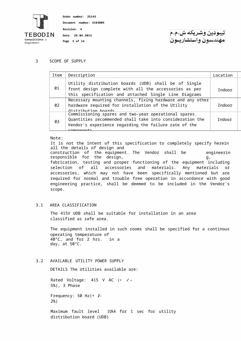
3 SCOPE OF SUPPLY
Item Description Location
01Utility distribution boards (UDB) shall be of Single front design complete with all the accessories as per this specification and attached Single Line Diagrams (Refer Attachment -2)
Indoor
02Necessary mounting channels, fixing hardware and any otherhardware required for installation of the Utility distribution boards Indoor
03
Commissioning spares and two-year operational spares.Quantities recommended shall take into consideration theVendor's experience regarding the failure rate of the components.
Indoor
Note:It is not the intent of this specification to completely specify herein all the details of design andconstruction of the equipment. The Vendor shall be responsible for the design, engineering,fabrication, testing and proper functioning of the equipment including selection of all accessories and materials. Any materials or accessories, which may not have been specifically mentioned but are required for normal and trouble free operation in accordance with good engineering practice, shall be deemed to be included in the Vendor's scope.
3.1 AREA CLASSIFICATION
The 415V UDB shall be suitable for installation in an area classified as safe area.
The equipment installed in such rooms shall be specified for a continous operating temperature of40°C, and for 2 hrs. in a day, at 50°C.
3.2 AVAILABLE UTILITY POWER SUPPLY DETAILS
The Utilities available are:
Rated Voltage: 415 V AC (+ /- 5%), 3 Phase
Frequency: 50 Hz(+ I- 2%)
Maximum fault level 1OkA for 1 sec for utility distribution board (UDB)
4 DESIGN & MANUFACTURING
4.1 415V UDB shall conform to this specification and all the attachments. UDB incomer fuse shall be capable of reducing the fault current from 50kA to less than 1OkA Accordingly fuse to be selected.
4.2 The Vendor shall indicate in the Table of Compliance, an itemised list of any exceptions to specification and its attachments.
comments or
TEBODINConsultarJts & Er1gir1eers
Tebodin & Partner LLC SpecificationOrder number: 25145
Document number: 4183005
Revision: A
Date: 29.04.2013
Page 6 of 14
4.3 415V UDB shall be single front, metal clad, air insulated Form-2B type design and shall be suitable for Indoor & wall mounted installation.
4.4 Only Front access shall be provided. All necessary supports, anchor bolts and packing pieces, etc. as may be required for installation of distribution board shall be in Vendor's scope. All equipment Icomponents supplied shall be of purchaser approved make and type only. 415V UDB shall be designed for bottom cable entry. The thickness of the gland plate shall be 3mm.
4.5 A drawing holder shall be provided inside the distribution board of A4 size. Neutral busbar of UDBshall be same size of phase busbar.
4.6 Degree of protection of minimum IP42 in accordance with IEC 60529 shall be maintained for the415V Distribution Board. Exposed parts within the assemblies that have to be accessible during normal operation, maintenance or equipping of spare compartments, shall either not be live in the opened position or shall be protected to a degree of protection of at least IP 2X.
4. 7 Construction of the panel shall be such that all components carrying AC power shall be fullyshrouded suitably, so that power carrying components shall not be accessible when door is open. Any auxiliary power required for indication lamps & other components shall be derived internally. All wiring for external connections shall be brought out to individual terminals on a readily accessible terminal block.
4.8 Wherever applicable switches shall be of the manual operating, air-break type with quick snapaction make and break features. They shall comply with and shall be type tested according to IEC60947-3. Switches shall be easily accessible and operable from the front of the UDB withoutopening a cover. Switches shall have a rated short-circuit making capacity in conformity with the prospective short-circuit currents of UDB. All switches used for isolating a circuit shall be padlock able in the 'OFF' position. All fuses shall be high breaking capacity (HBC) type. Fuses shall be of type 'gG' (Fast acting general purpose fuse links). The rupturing capacity of the fuse shall be equal to the short circuit rating of the busbar system. The fuse shall have a visual indication for Blown fuse condition.
4.9 One no. NO contact for the fuse, contactor and ELCB shall be provided for remote indication. All shall be in parallel and wire to terminal block.
4.10 Minimum cross section for internal wiring of current transformer secondary circuits shall be 2.5 mm2 (min.), whereas for the control and signalling circuits it shall be 1.5mm2 (min.). Colour of current transformer circuit wiring shall be black. Other control wiring shall be of grey colour.
4.11 Earthing bus bar shall be provided inside the panel with 2 nos. external connection points.Equipment to be earthed using minimum 2.5 sq.mm green colour earth wires. All equipment shall have a duplicate earthing with loops, so that even in the case of a loop chain being broken, the earth continuity of the metallic parUequipment to the main earth bar remains intact.
4.12 Secondary terminals of current transformers shall be wired up to a heavy duty terminal block with short circuiting links, located in the control compartment of the associated circuit. At this terminal block, one side of the current transformer shall be connected to earth through a removable link. Allcurrent transformers shall be earthed at one point only. Instrument safety factor (ISF) for metering core shall be 5. Current transformer shall have thermal rating equal to that of DB.
the
4.13 All instruments shall be flush mounting type and shall have IP 52 protection. Indicating instruments shall be in accordance with the relevant IEC standards and have an accuracy class as mentioned in attachment-2. Analogue meters should be of the square pattern type 96 x 96 mm, and mounted at a suitable height for easy reading from the front. Scales shall be in actual values.

title: Specification for Utility distribution boardCLIENTS\25145 AROGAS-DD For Upgrade Of WI Arld WT Facility\Project Archive\Temporary Archive\Dept 41 Electricai\Documents\4183005-Rev A LV UDB Specification\4183005
Utility Distribution Board Specification.Docx

Order number: 25145
Document number: 4183005
Specification
Revision: A
T E B 0DIN Date: 29.04.2013
Consultants & Engineers ' Page 7 of 14
4.14 415V UDB shall be supplied only from purchaser approved manufacturers & same shall be designed for a minimum operational life of 25 years.
4.15 UDB shall have padlocking facility. 20% spare terminals to be considered in each UDB terminal block. Each UDB shall have a separate Tag Plate indicating number as per attachment-2.
4.16 Cable glands & lugs are excluded from scope of supply. Commissioning will be by purchaser.
5 EARTHING
An adequately rated tinned copper earth bus shall be provided inside UDB and firmly bolted to the cubicle. The earth bus shall be capable enough to handle the full short circuit current of the UDB. The earth bus shall be located approximately 50mm above the bottom of the panel. The earth bus shall be color coded with green sleeves at regular intervals.
Two earth connectors shall be provided on the earth bus, one on each end section of the bus for connection to substation earthing system. All hinged doors and panels shall be properly earthed by flexible earth wires at least at two different locations.
6 PAINTING
UDB paint shade shall be RAL-7036. Painting procedure shall be as per international standard and shall be submitted for approval.
7 NAME PLATE AND LABELS
Name, identification, instruction and warning plates and their fixing materials shall be of durable, corrosion resistant material. They shall be provided with indelible inscriptions in English. All labels and plates shall be fixed by means of durable self-threading screws.
Nameplate information
The following information shall be given on the nameplate installed outside the assembly:
a) Manufacturer's name
b) Project name & number
c) Reference standard
d) Customer's purchase order number
e) Equipment title and tag number
f) Year of manufacture
g) Service voltage
h) Rated frequency
i) Rated current of busbar system
j) Rated voltage of auxiliary circuits
k) Rated peak and short time withstand current and withstand time
I) Degree of protection.

TEBODINConsultants & Engineers
Order number: 25145
Document number: 4183005
Revision: A
Date: 29.04.2013
Page 8 of 14
Specification
8 TYPE TESTS
Reports of UDB type test that has been carried out in an independent testing laboratory in accordance with IEC-61439-1 shall be submitted with the bid.
Following Type Test Certificates for 10kA rating shall be furnished as per IEC-61439.1) Temp. rise limits Test
2) Dielectric Properties
3) Short circuit withstand
4) Effectiveness of the protective circuit
5) Clearances and creepage distances
6) Mechanical Protection7) Degree of Protection
Components installed within the UDB assembly shall have been type tested in accordance with IEC-60947. Certificates obtained from the manufacturer of the components shall be made available at the request of the purchaser.
9 ROUTINE TESTS
Before dispatch, the Manufacturer shall carry out the routine tests in accordance with IEC 61439 on the total assembly in presence of third party inspector and the results shall be recorded in a test report. Vendor shall submit Factory test plan for approval. Inspection and tests shall be carried out on the complete UDB. UDB shall be visually inspected for conformity with the latest issue of the approved drawings and with the order. In addition to the routine tests specified in the IEC, the following shall be verified:
Degree of protection of the enclosure Clearances between live conductors Insulation of the busbar system Proper mounting of components Internal wiring and cabling system
Correct wiring of main and auxiliary circuits
Suitability of clamping, earthing and terminating arrangements
Correct labelling of functional units Completeness of the data on the nameplate Availability of the earthing system
Interchangeability of electrically identical components
Testing of the mechanical and electrical operation of a number of functional units on a random basis, including their control and protective devices.Primary injection and secondary injection tests
Checking of control schematics
Measurement of Insulation resistance using motorized megger before & after HV test
A dielectric test shall be carried out in accordance IEC 61439. The test voltage shall be as follows:
Minimum test voltage
For main circuits 2500 V (a.c.)
For control and auxiliary circuits 2xUn+1 000 V (a.c.),with a minimum of 1500 V
c!'?. til!.c':.Specification for Utility distribution boardCLIENTS\25145 AROGAS-DD For Upgrade Of WI And WT Facility\Project Archive\Temporary Archive\Dept 41 Electricai\Documents\4183005-Rev A LV UDB Specification\4183005
Utility Distribution Board Specification.Docx

TEBODINConsultants & Engineers
Tebodin & Partner LLC SpecificationOrder number: 25145
Document number: 4183005
Revision: A
Date: 29.04.2013
i Page9of14
10 SPARE PARTS
The manufacturer shall supply all required commissioning spares and the price for the same shall be built in the offer. The manufacturer shall quote for 2 years maintenance spares separately. The list of required maintenance spares along with its unit price shall form part of his bid.
11 DOCUMENTATION REQUIREMENTS
Supplier shall provide documentation in accordance with, but not limited to, the requirements mentioned in this specification. All aspects of the system operation and maintenance shall be fully documented. All documents shall be in English language and shall be submitted on electronic media. Final drawing shall be submitted in Autocad with Daleel Logo/drawing numbers. Two sets of hard copy of all documents shall be submitted.
12 INFORMATION TO BE SUBMITTED
Vendor shall provide the following minimum documentation I details with the tender.
• Heat load details per UDB
• General Arrangement Drawing indicating main circuits, main dimensions, panel layout, floor plan, minimum clearances required for ventilation and safety during operation & maintenance
• Total mass of the assembly
• Duly filled technical data sheets
• Single Line Diagram• Schedule of recommended spare parts
• Technical documentation for offered equipment
• Guaranteed technical particulars
• Delivery schedule• Brochures and catalogue
• Type test certificates
• Manufacturing schedule• Quality Assurance Plan
• Filled up Table of Compliance
• Transport, installation, commissioning, operation and maintenance instructions, limited and specific to the assembly and its components
• Panel inside & outside paint shade
• Static and dynamic loading of the panels for Civil design
Vendor shall provide the following documentation I details after placement of order in addition to the above documents.
• Schematic diagrams for different types of circuits
• Bill of Material• Wiring diagrams showing all external cable connections and terminal assignments
13 DELIVERY
The material shall be delivered at PURCHASER's Muscat store I site store as per purchase enquiry document.
title: Specification for Utility distribution boardCUENTS\25145 AROGAS-DD For Upgrade Of WI And WT Facility\Project Archive\Temporary Archive\Dept 41 Electrica!\Documents\4183005-Rev A LV UDB Specification\4183005
Utility Distribution Board Spedfication.Oocx
TEBODINConsultar!ls & Engineers
Tebodin & Partner SpecificationOrder number: 25145
Document number: 4183005
Revision: A
Date: 29.04.2013
Page 10 of 14
14 SUPPLIER'S RESPONSIBILITY
The SUPPLIER shall be responsible for all activities including transportation, intermediate storage, payment of all custom duty, port clearance charges etc. until safe delivery of the material to the PURCHASER's store in Oman as per purchase enquiry document. Any damage incurred during transportation shall be to SUPPLIER's account.
15 WARRANTY
The SUPPLIER shall provide warranty for the supplied items for 18 months from date of delivery or12 months from date of commissioning whichever is longer.
title: Specification for Utility distribution boardCLIENTS\25145 AROGAS·DD For Upgrade Of WI And WT Facility\Project Archive\Temporary Archive\Dept 41 Electricai\Documents\4183005-Rev A LV UDB Specification\4183005
Utility Distribution Board Specification.Docx

Specification
Ref. Section
SUPPLIER Ref:
Conforms: YIN Alternative: YIN Noted: YIN Clarifications•
1.11.22.12.23.03.1
3.2
4.1
4.24.3
4.4
4.54.64.74.84.94.104.114.124.13
4.144.154.1656
7891011
1213
141516Attachment - 1Attachment- 2
l1TEBODINConsultants & En1;ineers
Tebodin & Partner LLC SpecificationOrder number: 25145
Document number: 4183005
Revision: A
Date: 29.04.2013
Page11 of14
16 TABLE OF COMPLIANCE
The SUPPLIER shall confirm that he has accepted all the clauses contained in the specification or otherwise made clarifications I exceptions to be noted below:
• The SUPPLIER shall submit all the associated clause number indicating page number of applicable codes, standards and references with supporting documents as applicable for PURCHASER's review.
I'3rt. tl :.Specification for Utility distribution board!. E .CLIENTS\25145 AROGAS-DD For Upgrade Of WI And WT Facility\Project Archive\Temporary Archive\Dept 41 Electricai\Documents\4183005-Rev A LV UDB Specification\4183005
Utility Distribution Board Specification.Docx
TEBODINConsultants & Engineers
Order number: 25145
Document number: 4183005
Revision: A
Date: 29.04.2013
Page12of14
17 ATTACHMENTS
17.1 ATTACHMENT-1: UTILITY DISTRIBUTION BOARD DATA SCHEDULE
17.2 ATTACHMENT-2 SINGLE LINE DIAGRAM OF 415V UTILITY DISTRIBUTION BOARDS
R ; · ,f; ;;:;;::;;for Utility distribution board:: AROGAS-DD For Upgrade Of WI And WT FaGility\Project Archive\Temporary Archive\Dept 41 Electricai\Documents\4183005-Rev A LV UDB SpeGification\4183005
Utility Distribution Board Specification.Docx
Tebodin
Order number: 25145
Document number: 4183005
Revision: A
TEBODIN Date: 29.04.2013
Specification
Consultants & EngineersPage 13 of 14
17.1 ATTACHMENT-1: UTILITY DISTRIBUITION BOARD DATA SCHEDULE
title: Specification for Utility distribution boardCLIENTS\25145 AROGAS-DD For Upgrade OfW1 And WT Facility\ProjeGt Archive\Temporary Archive\Dept 41 Electricai\Documents\4183005-Rev A LV UDB Specification\4183005
Utility Distribution Board Specification.Doell

ATTACHMENT 1 Page: 1 of 1
415V Utility Distribution Board
1 REQUIREMENTS AND CONDITIONS
2 General
3 Standard
4 Schedule · 2 Nos. Distribution Boards as per SLDs under Attachment-2 of specification
5 Power system type . TN-S/ Voltage: 415 v; Frequency: 50 Hz
6 Electrical supply characteristics · As per specification {specify details)
7 Rated current of busbar system DB-1501 75A, DB-1502100A
8 Prospective short time withstand current 10kA n: as per IEC I 1sec
9 Service conditions : As per specification
0 Location Land installation 'QffsRme iAstallatieR; indoors 'a cJtSeers
1 Special service conditions Indoor
2 Cubicle illumination lamp I Socket : yes-/ no
3 Special transport conditions no I
14 Anti condensation heaters required : y-e&-1 no
5 Type of enclosure metal I insldlating mateFial mldlti sld9isle 'mldlti Qm(
16 Measuring Instruments : analogue /-Gigftal-
17 Transducers required for signals to DCS no I 1 es, Eletails SFJesifieS seFJaFateiJ
18 Type of mounting : Wall Mounted
9 Framework required :yes Cable entries incoming: bottom
20 Type of fuses DIN I BSI outgoing: bottom
21 Witnessed routine testing I inspection :yes Cable gland plate undrilled
22 Special tests required no Glands required : No
23 Language on equipment English Glands type NA24 Language on documentation English Padlock hasp size 6mm I mm minimum
25
2627
28 Make and typeINFORMATION TO BE SUBMITTED BY MANUFACTURER WITH THE QUOTATION
29 Manufacturing location : Assembly. , Main Components·
30 Rated short-circuit strength : thermal: kA rms, 1s; dynamic: kA crest
31 IMCS type na (attach details)
32 Type of enclosure
33 Type of mounting
34 Degree of protection IP
35 Anti condensation heaters included yes I no
36 Rain canopy ·yes/no
37 Total mass of equipment kg•
38 Specified tender documentation attached yes I no
39 Any deviations from specification no
40 (if yes, list deviations)
4 1 Heat load Watts
42 Switching duty type of all switches
43
4445 SPECIAL REQUIREMENTS AND REMARKS REMARKS ON REVISIONS
46
47
48
49
50
51
Made by: Date EQUIPMENT: 415V Utility Distribution Board Rev. letter A
SAG 29/04/13 Date 29/4/13
Chked by: Date CLIENT : Daleel Petroleum Sign.
DKL 29/04/13
Appr. by: Date Sheet No. 1
MSK 29/04/13
Eng. by Tebodin LLC Equipm. No.--
EPC AROGAS Req. No.I--
T:\OTHER CLIENTS\25145 AROGAS-DD for Upgrade of WI and WT Facility\Project Archive\Temporary Archive\Dept 41Electricai\Documents\4183005-Rev A LV UDB specification\Attachment-1_UDB_Data Sheet

l1TEBODINConsultants & Engineers
Tebodin & Partner LLC SpecificationOrder number: 25145
Document number: 4183005
Revision: A
Date: 29.04.2013
Page 14 of 14
17.2 ATTACHIIJIENT-2: SINGLE LINE DIAGRAM OF 415V UTILITY DISTRIBUTION BOARDS
title: Specification for Utility distribution boardCLIENTS\25145 AROGAS-DD For Upgrade Of Wl And WT Facility\Project Archive\Temporary Archive\Dept 41 E!ectricai\Documents\4183005-Rev A LV UDB Specification\4183005
Utility Distribution Board Specification.Docx

e
·'
'
'
., 1""jI
"'ell!=.,_.. •-r--- J
'
c..,..
'1
-r •
g 1-r •
fI
: -r!
: 29
m
: ·-<
II
'.,
":•·'I d i '
'r"' " :1
•
,-----------------------
;.
I 0
!'--.,_..
'
' 5iiiI "' 1-
1:"g• !'-.,_..•
II
I 1":- •
3 '9dS
3 '1'dS
3 \ldS
( 00J. VFJ/!'jOQ VJ H:JJ.IMS)1311110 13>1005 Nl'l' NI
' II
I 1'---J''I
-k----- '=' - -(1'100ll 3 QiS
' •
• r--- J_}_'2f/1'100ll HV3 HJHIIS/lO!:Il.NOJ)
IT11110 lJ)IJOS NIVI'1 NI
D.Ll i'jQQlJ W3<1HOltMS Ill
'!
1;12!1'
I'
1:"'
r' --- ":'. JI 1:" •
I .,_.. • r--- ":'... J
D.L1l '100lJ W3<1HO!IMS 111
Dll 1'100.l.!f.3.ilYEl
'
I. ' •'
.,_.. 0 r' --- U:'• '0 '< Oll 1'100lJ lO&NOO
I·.!. '-r •- --- ":'_ ..
ru1 1'100lJ JlJOlS
' !f gg;I 'l
... t:
"' ::ll!i25
'--- '='- J
Oll I'IOOlJ lO!:Il.NOO
il< t
z .-rail
-r
- u'
3 VdS
J VdS
3 VdS
'"'-r
".•iii
t 'e
!.,_.. •ww·l>; 91cy,
-------------
ONimlnB 10li1No:> ONimn l'INlllW
ONtLn O W. l:I31'1HO-"SNVlli'I' O!:IV.l.H::UL\15
!« ! if -;,;" £ •• • I -------------
'>•
A
)lll!,_ ' •Nlln a J. l:I31'1HO.JSN l!L
f!llI
' s " !
-r ·-r-- - - 1_
'I' Oll'f.l.HJlL\\S
:Ul mxn; V3 V
; ':;!' -r • r-- - - 1_'2!:
iii,l.:.161 • · 1' • r' - ":'_":'_ _!l_'2!:
0" I

iigl -r"ii:;l u [•--@--_---------------------------
= 1·
ll illHS dYmd lN:31'11V3!1L !illVAI

I
' '•II hI'a
'",, "8 l I' ._....'!jj'r$ :1 •
r·· -------- --- . :w=-J JH•! -----·-1
I
I
I