Embed Size (px)
Citation preview

1
NXM2G DESCRIPTIONThe NXM2G system is a microprocessor based boiler load optimization control systemdesigned to provide optimum thermal efficiency of Low Temperature Hot Water (LTHW) boilers.
Control theory
The NXM2G measures the supply (flow) and return temperatures via digital sensors (supplied) andmonitors the “call for heat” via the Opto-isolators from the limit string wiring connections.
• On first firing, the boiler will reach the normal cut out set point and turn off,
• On the next burner cycle, the NXM2G will check:
i) for the “call for heat ”
ii) if the boiler flow and return temperatures are within the designed temperature differential settings (parameter), and
iii) if the boiler is required to fire, based on control algorithms.
When this occurs, the NXM2G will hold off the boiler firing (save mode) based on temperature andtime, which are both adaptive. The NXM2G will also inhibit the burner from firing on stage 2, if theboiler load demand is low, thus ensuring the best efficiency for the current system demand.
NXM2G interface wiring
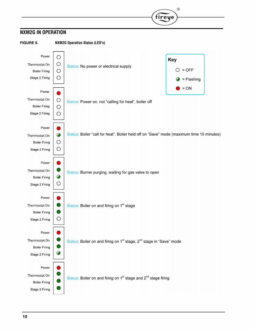
The NXM2G has 2 normally closed relays which are failsafe. These relays are wired in series to the1st and 2nd stage operating control circuits. The relays operate according to whether the boiler is insave mode or low fire save mode. The NXM2G has a series of LEDs that give the following indica-tions:
• Power 120 VAC applied
• Thermostat on Call for heat / 1st Stage thermostat closed
Blinking: "Save" mode
Steady: Boiler allowed to fire
WARNING: • The installer must be suitably qualified and trained to install NXM2G. • Follow the boiler manufacturer’s instructions.
NXM2GInstallation and
Operating Manual
40VG
NXM2G-1001MARCH 26, 2014
This manual must be affixed on or adjacent to the boiler or kept with boiler operating manual or other information.
(-1 UL version shown)
2
• Boiler firing Call for heat / Boiler allowed to fire
Blinking: Burner purging
Steady: Boiler allowed to fire (or fuel valve open)
• Stage 2 firing Call for heat / 2nd Stage thermostat closed
Blinking: "Low Fire Save" mode
Steady: Stage 2 firing
Failsafe operation
In all cases the safety integrity of the boiler operation is not compromised. Moreover, the boiler set pointis always maintained. Should the NXM2G unit fail or lose electrical supply the boiler control system wir-ing remains as normal and the boiler will operate as if the NXM2G were not installed. The boiler’s oper-ating control is always in circuit and protected with the boiler high temperature limit.
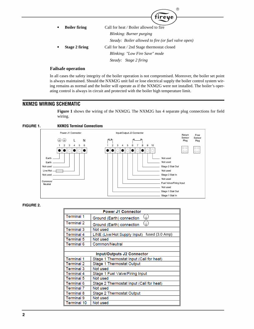
NXM2G WIRING SCHEMATICFigure 1 shows the wiring of the NXM2G. The NXM2G has 4 separate plug connections for fieldwiring.
FIGURE 1. NXM2G Terminal Connections
FIGURE 2.
fused (3.0 Amp)

3
Power Wiring
It is required that the NXM2G device be powered via a Listed isolation switch. The NXM2G may bepowered from the same isolated supply provided that the branch circuit protection or fuse locatedwithin the isolator (if present) is rated at 7A or less. Where the NXM2G circuit protection exceeds7A, the supply for the NXM2G from the isolated supply shall include a supplementary fuse rated at3A."
The wiring associated with the control circuits (J2) shall be protected by an overcurrent device ratedat not more than 7A. Overcurrent protection may be incorporated into the controlled devices
NXM2G SPECIFICATIONS
The right to make changes in specification or design at any time without prior notice is hereby reserved.
NXM2G System Model NXM2G
Supply Voltage: 120V AC / 60Hz
Rated Current: 50mA
Relay Switching Capacity: 2A at 120V AC (resistive)
Fuse Rating: 1.6A @ 120 V AC
Dimensions: 6.9” (175mm) W x 7.9” (200mm) H x 2.1” (54mm) D
Sensors: Plug in Digital Thermometer (2)
Sensor Range: 131°F to 257°F (55°C to 125°C)
Weight: 3.6 pounds (1.6kg)
Case: Painted Metal
Environment: NEMA 1 / IP11Note: Casing not intended for outdoor installation. For outdoor installations the device should be enclosed in an appropriate utility box (NEMA 3 or better).
Maximum Operating Temperature Limits: 125°F (52°C)
Minimum Operating Temperature Limits: 32°F (0°C)
Maximum: Mounted surface temperature 104°F (40°C)
Humidity: 85% R.H. Maximum (Non-Condensing)

4
SUITABLE NXM2G APPLICATIONSThe NXM2G operates on:
• Low temperature hot water (LTHW) boilers fired with:
on/off forced draft burners
two stage high/low burners
modulating burners
• Atmospheric boilers fired with:
two stage burners
modulating burners
Wiring Diagrams
FIGURE 3. Typical Wiring for single stage atmospheric boiler
3.0Amax
7.0 Amax
SUPPLY FUSE

5
FIGURE 4. Typical Wiring for single stage forced draft burner
FIGURE 5. Typical Wiring for 2 stage High/Low force draft boiler
7.0 Amax
7.0 Amax

6
INSTALLING THE NXM2G
Before installing the NXM2G
1. Ensure that all boiler equipment is suitable for an NXM2G installation.2. Ensure that all boiler equipment is fully functional.
Installing the NXM2G
• Mount the NXM2G wiring base on the boiler casing or on a suitable adjacent surface.
• The location should be
free from excessive vibration
within the specified ambient temperature rating (i.e away from hot surfaces).
• The NXM2G base can be mounted in any angular position
When choosing a place to locate the NXM2G, ensure that
1. The position of the NXM2G does not obstruct the boiler access panels used for maintenance
2. The NXM2G LEDs can be viewed without restriction.
CAUTION: Electrical supply to the boiler and burner must be isolated during the installation process.
CAUTION: Ensure that the mounting area for the NXM2G is free from hidden
other obstructions. cables and electrical
CAUTION: All wiring should comply with applicable electrical codes, regulations
conditions. Use moisture / heat resistant color coded multi core cable. The NXM2G must be correctly grounded (earthed) to provide a minimal
AC quality problems.
for local
effect of
7
TYPICAL NXM2G INSTALLATION PROCEDURES
When installing the NXM2G, the following procedures must be followed:
• Remove the bottom wiring cover. Select the required conduit size and connections for the field wiring to the boiler controls and temperature sensors.
• Use suitable screwed fasteners such as self tapping screws. Only use the holes provided in the wiring compartment for mounting the NXM2G.
• For top mounting, use only mounting screws and brackets provided.
• Use conduits to run wires to connect the boiler thermostat/s or boiler control panel to theNXM2G.
• Conduits must be used to run the flow and return sensor wires to the NXM2G.
• Use colored multi-core cable to make the various connections between the boiler and the NXM2G.
• Remove the plug connectors from the wiring compartment. As in Figure 1. using the cable anchor provided, use cable ties to secure cables in the wiring compartment.
• Connect mains L, N and E (Ground) to the connector and plug into the NXM2G as in Figure 1. The L, N and E (Ground) must be on the same electrical phase as the boiler/burner’s electrical supply.
WARNING: Do not use the internal PCB area to secure the NXM2G – doing so will
warranty void the
TIP: Before installing the temperature sensors inside the conduits, mark either or both the flow or return sensor(s) with colored tape at both ends of the cable(s). This helps to ensure correct orientation when inserting the plugs into the NXM2G connectors. i.e. the supply (flow) sensor plugs into the supply (flow) connector on the NXM2G and the return sensor
into the return connector on the NXM2G. plugs
8
• Locate the required boiler thermostat(s). Connect to the switched side of the thermostat contacts,as shown in Figure 1.
• Use the boiler/burner manufacturers wiring diagrams to determine the connections to the NXM2Gas in Figure 1.
• Wire the connector as in Figure 1.
• Plug the connector into NXM2G as in Figure 1.
• The supply (flow) and supply return temperature sensors need to be fixed to the correct boiler pipework connections; this should be as close to the boiler as possible. This may require the pipe workinsulation to be removed. Using appropriate banding (clamp), secure the sensors to the pipe.
Please note: Do not over tighten, as this may damage the sensor.
Replace the pipe work insulation on completion. Plug the correct supply (flow) and return sensorsinto the NXM2G terminal as detailed in Figure 1.
• Ensure that all connections, including ground/earth connections, are secure. Replace covers withscrews provided.
WARNING: Ensure that the NXM2G mains electrical supply is on the same phase
/ burner’s electrical supply. as the boiler

9
NXM2G COMMISSIONING AND FUNCTIONAL TESTSBefore commissioning the NXM2G check the following:
1. The NXM2G has been correctly positioned and is securely mounted to the mounting surface2. The connectors in the NXM2G have been correctly wired to boiler/burner.3. The electrical supply voltage and phase are powering the NXM2G correctly.
Commissioning the NXM2G on the boiler can now begin by following the steps below:
1. Power up the boiler and burner.2. Observe LED status. (Refer to Figure 6 on following page)3. Note: during “power up” all LEDs will be illuminated for a short time.4. Confirm operation for Thermostat on and Boiler firing LEDs and check for “Boiler firing
mode”. This will allow the burner/boiler to start without interruption (i.e. not in save mode) whenthe NXM2G is powered for the first time. (see Figure 6 ).
5. Operate the boiler thermostat (boiler firing) to stop the boiler/burner firing. Then reset the ther-mostat to “call for heat” and check that the NXM2G initiates the “save mode” with the Thermo-stat On LED flashing.
6. Operate boiler thermostat (stage 2 firing) if applicable and check second stage “first firing” mode(see Figure 6 )
7. Operate boiler thermostat (stage 2 firing) to reduce boiler firing to 1st boiler firing. Then resetthe thermostat to “call for heat” and check that the NXM2G initiates the “save mode” Stage 2 fir-ing LED now flashing.
8. Isolate the boiler/burner and repeat the above procedures.9. In the event that the NXM2G does not operate as in Figure 6, isolate boiler/burner and check all
wiring connections, and repeat steps 1 to 7.
10
NXM2G IN OPERATION
FIGURE 6. NXM2G Operation Status (LED's)
11
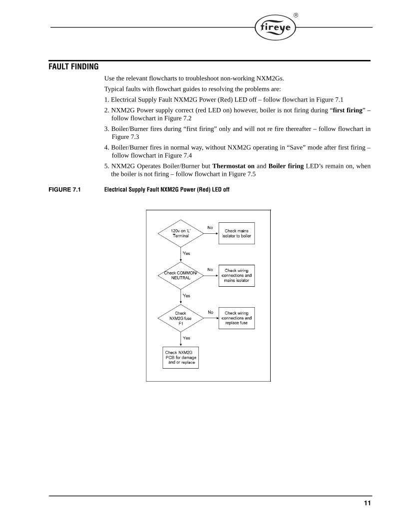
FAULT FINDINGUse the relevant flowcharts to troubleshoot non-working NXM2Gs.
Typical faults with flowchart guides to resolving the problems are:
1. Electrical Supply Fault NXM2G Power (Red) LED off – follow flowchart in Figure 7.1
2. NXM2G Power supply correct (red LED on) however, boiler is not firing during “first firing” –follow flowchart in Figure 7.2
3. Boiler/Burner fires during “first firing” only and will not re fire thereafter – follow flowchart inFigure 7.3
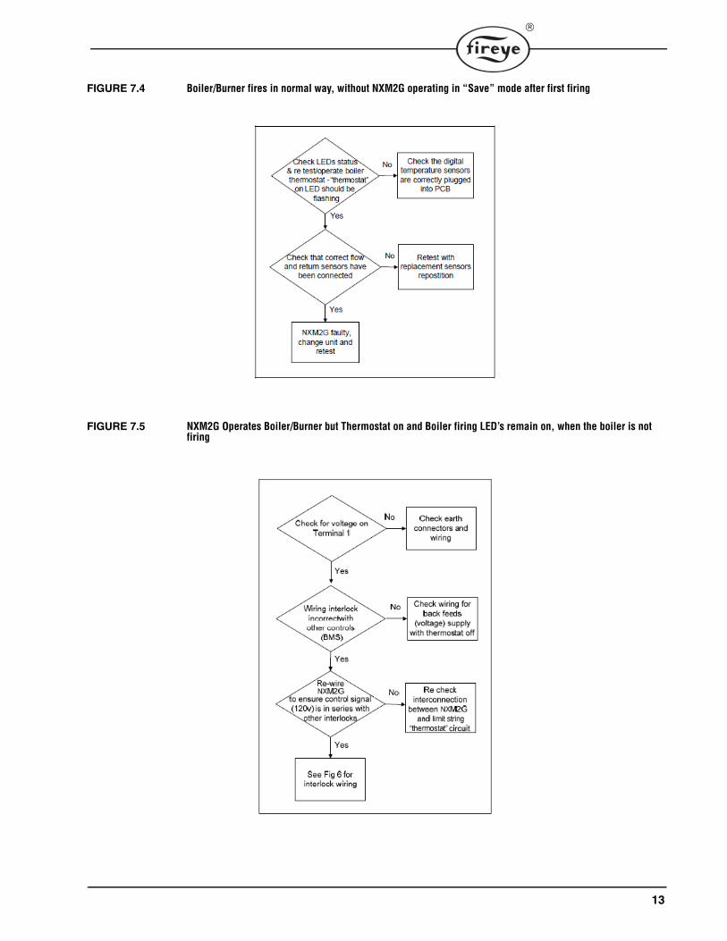
4. Boiler/Burner fires in normal way, without NXM2G operating in “Save” mode after first firing –follow flowchart in Figure 7.4
5. NXM2G Operates Boiler/Burner but Thermostat on and Boiler firing LED’s remain on, whenthe boiler is not firing – follow flowchart in Figure 7.5
FIGURE 7.1 Electrical Supply Fault NXM2G Power (Red) LED off

12
FIGURE 7.2 NXM2G Power supply correct (red LED on), however boiler will not fire during “First Firing”
FIGURE 7.3 Boiler/Burner fires during “First firing” only and will not re-fire thereafter
13
FIGURE 7.4 Boiler/Burner fires in normal way, without NXM2G operating in “Save” mode after first firing
FIGURE 7.5 NXM2G Operates Boiler/Burner but Thermostat on and Boiler firing LED’s remain on, when the boiler is not firing

14
FIGURE 7.6 NXM2G Interlock Schematic
NXM2G interlock schematic, showing the correct positioning of the NXM2G in the boiler controlcircuit.
NOTICEWhen Fireye products are combined with equipment manufactured by others and/or integrated intosystems designed or manufactured by others, the Fireye warranty, as stated it its General Terms andConditions of Sale, pertains only to the Fireye products and not to any other equipment or to thecombined system or its overall performance.
WARRANTIESFIREYE guarantees for one year from the date of installation or 18 months from date of manufactureof its products to replace, or, at its option, to repair any product or part thereof (except lamps, elec-tronic tubes and photocells) which is found defective in material or workmanship or which otherwisefails to conform to the description of the product on the face of its sales order. THE FOREGOINGIS IN LIEU OF ALL OTHER WARRANTIES AND FIREYE MAKES NO WARRANTY OFMERCHANTABILITY OR ANY OTHER WARRANTY, EXPRESS OR IMPLIED. Except asspecifically stated in these general terms and conditions of sale, remedies with respect to any productor part number manufactured or sold by Fireye shall be limited exclusively to the right to replace-ment or repair as above provided. In no event shall Fireye be liable for consequential or special dam-ages of any nature that may arise in connection with such product or part.
FIREYE NXM2G-10013 Manchester Road MARCH 26, 2014Derry, New Hampshire 03038 USA supersedes March 18, 2013www.fireye.com


![Modern Boiler Types and Applicationsdocshare01.docshare.tips/files/2173/21738414.pdfFigure 9. PCF-boiler with horizontal coal firing with two-pass layout [2]. Figure 10: Oil or Gas](https://img.dokumen.tips/doc/110x75/613b0a22f8f21c0c8268c773/modern-boiler-types-and-ap-figure-9-pcf-boiler-with-horizontal-coal-firing-with.jpg)


![MBC - Multiple Boiler Control · 2010-11-19 · Ideal for multiple boiler systems or . applications firing large capacity boilers with stage capability. . PN 240012795 Rev. [10/11/19]](https://img.dokumen.tips/doc/110x75/5fb1b90c4dfdfc693f271593/mbc-multiple-boiler-control-2010-11-19-ideal-for-multiple-boiler-systems-or.jpg)


