Embed Size (px)
Citation preview

TESTING OF THE
STOKERMASTER BOILER CONTROL
SYSTEM
Submitted to the
Legislative Commission on Minnesota Resources by
Minnesota Department of Natural Resources October 1988
Contact: Ronald D. Visness Mineral Development Manager (612) 296~9562
This document is made available electronically by the Minnesota Legislative Reference Library as part of an ongoing digital archiving project. http://www.leg.state.mn.us/lrl/lrl.asp (Funding for document digitization was provided, in part, by a grant from the Minnesota Historical & Cultural Heritage Program.)

TABLE OF CONTENTS
Introduction . . . . . . . . . . . . . . . . . . . . . . . . . . . . . . . . . . . . . . . . . . . . . . . . . . . . . . . 1
E . s .. xecut1ve ummary ................................................. 11
StokerMaster Devices ............................................... 1
Existing Boiler Control System at the South Middle School ......................................... 3
Test Procedure ..................................................... 3
Test Results ....................................................... 6
Graphic Presentation: Fuel Flow vs. Steam Pressure ..................................... 8 Opacity vs. Fuel Flow ............................................ 9 Opacity vs. Fuel Flow ............................................ 9 Combustibles vs. Fuel Flow ...................................... 10 Opacity vs. Time ............................................... 11 Combustibles vs. Time .......................................... 11 Steam Pressure vs. Time ......................................... 11
Conclusions ....................................................... 12
Recommendations ................................................. 14
Appendix A: Stoker Master Performance Evaluation Phase I . . . . . . . . . . . . . . . . . . . . 15

TESTING OF THE STOKERMASTER BOILER CONTROL SYSTEM
INTRODUCTION
Over the last ten years the state and other public agencies have modified existing boilers or, in some some cases, have installed new boilers to burn wood. The goal was to substitute a cheap and abundant indigenous fuel for a more expensive fuel originating outside the state. Today, many of the installations have poor efficiency ratings and/or emissions problems. The state recognizes that it has a responsibility to help boiler owners improve efficiency and reduce emissions.
StokerMaster is the trademark for a series of boiler control devices designed by Engineered Energy Concepts (EEC) of Kingsport, Tennessee. EEC claims that StokerMaster devices simultaneously improve efficiency and reduce emissions. A test program to evaluate these devices was designed by the Department of Natural Resources and submitted to the Legislative Commission on Minnesota Resources (LCMR) for its consideration. The primary objective was to determine whether new microprocessor-based control systems could be used to reduce emission levels and increase the efficiency of wood-fired boilers. A secondary consideration was to determine whether the same control system would allow boiler operators to switch from relatively high priced wood pellets to lower cost wood chips without creating localized emissions problems.
The LCMR approved the StokerMaster project in December 1986 as a two phase test. Phase I was a test of a StokerMaster II at the Independent School District (ISD) 318 Elementary School in Cohasset, Minnesota. Phase II was a test of a StokerMaster III at the South Middle School in Grand Rapids, Minnesota.
Phase I was completed in April 1987 and an interim report was given to the LCMR in June of that year. The LCMR approved Phase II testing for the 1987-88 heating season.
This report summarizes the results of both Phases, details the results of Phase II, and presents recommendations based on the results of the entire program.

EXECUTIVE SUMMARY
Phase I. Phase I consisted of testing a StokerMaster II 1 at the Cohasset Elementary School. The initial goals of the Phase I program were to determine whether a StokerMaster II control system fulfilled the claims of its inventor by simultaneously reducing particulate emissions and enhancing boiler performance. Before the testing began, these goals were supplemented to include continuous emissions monitoring (CEM) and the installation of an air preheater, which would allow for short tests of wood chips. Testing began on February 15 and concluded on March 27, 1987.
The major conclusions drawn from the Phase I tests were:
• The StokerMaster II reduced particulate emissions when compared to the old system which uses ON/OFF controls.
• Opacity levels were approximately equal in both systems when the stoker was operating 100 percent of the time. However, when the stoker was operating less than 100 percent of the time the StokerMaster II had lower opacity readings. This indicated that the StokerMaster II exhibited better overall control than the old system.
• The StokerMaster II generated a fuel savings of about 12 percent when compared to the old system.
• Use of the air preheater when high moisture wood chips were burned resulted in significantly lower emissions than when the preheater was not used.
• Boiler operability was improved with the StokerMaster II, as evidenced by reduced clinkering and less ash deposition in the boiler tubes and flues.
• The StokerMaster II consistently produced higher carbon monoxide levels (this may have resulted because the elimination of over fire air reduced the amount of turbulence in the furnace).
1 The StokerMaster II is a computer-controlled, electro-mechanical system designed for use with small commercial boilers in the 25 to 100 HP range having ON/OFF control systems.
ii

Results of the Phase I testing were encouraging and indicated that the Stoker Master II was an improvement over the old control system used at the school. Furthermore, results indicated that low-cost wood chips might be burned more efficiently using a StokerMaster control system. The need to verify these indications provided the rationale to proceed to Phase II.
Phase II. Phase II consisted of testing a StokerMaster III2 at the Grand Rapids South Middle School in May 25 and 26, 1988. The goal of Phase II was to compare the performance of a StokerMaster III with the existing control system when using wood chips. In addition to the StokerMaster III, the following equipment was installed at the school: a ceramic grate, an air preheater, a draft control damper, an oxygen and combustibles meter, and a computer for data collection. Four conditions were tested each day:
1. StokerMaster III with air preheater OFF
2. StokerMaster III with air preheater ON
3. Old control system with air preheater OFF
4. Old control system with air preheater ON
Data collected included:
opacity, combustibles, fuel flow, flue gas velocity, flue gas temperature, steam pressure, and outside air temperature.
Each variable was sampled every five seconds, and averaged over three minute intervals. The averages were stored on disk for analysis.
Hardwood chips having an average moisture content of 27.5 percent were used throughout the test.
The major conclusions of the Phase II testing were:
• The StokerMaster III performed better than the old control system when the air preheater was off (conditions 1 and 3, above). There was less variation in fuel flow and opacity was lower using the StokerMaster.
2 The StokerMaster III is a computer-controlled, fully modulating control system capable of varying f ucl and air rates independently. It uses proportion, integral, and derivative (PID) control devices to modulate all process variables.

• Adding load to the boiler eliminated opacity excursions with the StokerMaster Ill
• The air preheater eliminated the opacity excursions in the old system and reduced average opacity by about 1 percent for both systems (conditions 2 and 4, above).
• The air preheater reduced the level of combustibles in the flue gas by about 25 percent for both systems.
• Both systems were able to maintain effective control over steam pressure.
• The StokerMaster III performed marginally better than the old system, but did not vastly improve efficency or emissions.
• Operation of both systems were improved when the air preheater was used.
• The ceramic grate, designed by EEC, enabled the boiler to maintain higher average temperatures than were possible using the steel grate.
The data gathered at the test sites ~how that the StokerMaster devices can improve the operation of wood-fired boilers with ON/OFF controls, and that the use of ceramic grates and air preheaters improve operation with wetter fuels. Ceramic grates and air pre;heaters are two low-cost modifications that are easily implemented and result in an immediate improvement in boiler performance.
Current prices for the Stoker Master II, (approximately $3,600 FOB Kingsport, Tennessee) indicate that these devices may prove to be quite cost-effective if installation charges can be minimized.
iv
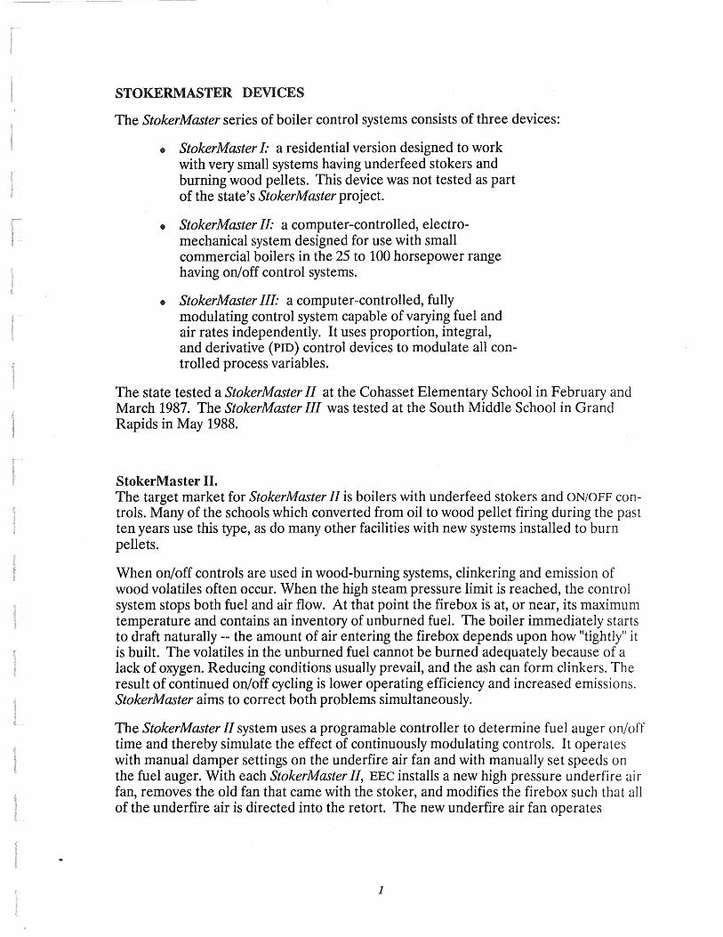
STOKERMASTER DEVICES
The StokerMaster series of boiler control systems consists of three devices:
e StokerMaster I: a residential version designed to work with very small systems having underfeed stokers and burning wood pellets. This device was not tested as part of the state's StokerMaster project.
e StokerMaster IL· a computer-controlled, electromechanical system designed for use with small commercial boilers in the 25 to 100 horsepower range having on/ off control systems.
• StokerMaster III· a computer-controlled, fully modulating control system capable of varying fuel and air rates independently. It uses proportion, integral, and derivative (PID) control devices to modulate all controlled process variables.
The state tested a StokerMaster II at the Cohasset Elementary School in February and March 1987. The StokerMaster III was tested at the South Middle School in Grand Rapids in May 1988.
StokerMaster II. The target market for StokerMaster II is boilers with underfeed stokers and ON/OFF controls. Many of the schools which converted from oil to wood pellet firing during the past ten years use this type, as do many other facilities with new systems installed to burn pellets.
When on/off controls are used in wood-burning systems, clinkering and emission of wood volatiles often occur. When the high steam pressure limit is reached, the control system stops both fuel and air flow. At that point the firebox is at, or near, its maximum temperature and contains an inventory of unburned fuel. The boiler immediately starts to draft naturally -- the amount of air entering the firebox depends upon how "tightly" it is built. The volatiles in the unburned fuel cannot be burned adequately because of a lack of oxygen. Reducing conditions usually prevail, and the ash can form clinkers. The result of continued on/off cycling is lower operating efficiency and increased emissions. StokerMaster aims to correct both problems simultaneously.
The StokerMaster II system uses a programable controller to determine fuel auger on/off time and thereby simulate the effect of continuously modulating controls. It operates with manual damper settings on the underfire air fan and with manually set speeds on the fuel auger. With each StokerMaster II, EEC installs a new high pressure underfire air fan, removes the old fan that came with the stoker, and modifies the firebox such that all of the underfire air is directed into the retort. The new underfire air fan operates
1

continuously. An air preheater can be added to the system to control emissions at low firing levels or as an aid to combustion of high moisture fuels.
The installed parts are standard and are readily available from various suppliers. The programable controller used is also commonly available. Equipment assembly and the algorithm used in the programmable controller are the unique elements supplied by EEC.
StokerMaster III. The target market for the StokerMaster III is larger boilers with either ON/OFF or partially modulating controls. Several of these were installed in high schools and colleges in Minnesota during conversion to wood firing. The StokerMaster III is designed to:
control fuel flow by modulating fuel auger speed control air flow by modulating damper settings control boiler draft by modulating dampers in the breeching
Optional equipment such as an air preheater or instrumentation such as oxygen or steam flow meters may also be connected. The heart of the unit is a programmable PID controller which transmits set point signals to fuel and air flow controllers. Again, the unique aspects of this system are the programs written by EEC and the assembly of the components.
2

EXISTING BOILER CONTROL SYSTEM AT THE SOUTH MIDDLE SCHOOL
The South Middle School installed a wood-pellet fired boiler in 1982. The boiler control system installed at the school uses the difference between the steam pressure set point and the actual steam pressure to increase or decrease fuel and air flows. This difference generates a fuel auger RPM value and an underfire air damper setting which attempts to hold boiler pressure steady at any given boiler load.
The actual operating ranges can be set manually by adjusting the length of lever arms which control damper positions. The upper limit of an operating range can be reduced by using a rheostat, which limits maximum voltage, thereby limiting maximum auger RPM and maximum underfire air damper opening. Several manual adjustments are needed if gross changes in boiler load occur. There is no mechanism to trim air/fuel ratios in order to improve boiler efficiency.
This type of control system has a tendency to "hunt" as it attempts to find the proper control settings. Operation without a fixed set point for fuel and air flow usually is not critical since the building heat demand also changes over time. Also, a system which is sized properly for maximum boiler output will likely operate with large volumes of excess air at lower outputs unless dampers and augers are set manually to maintain better air/fuel ratios.
TEST PROCEDURE
The Phase II tests performed at the South Middle School on May 25 and 26, 1988 were designed to determine whether a Stokermaster III control system improved boiler performance and produced less emissions than the old control system. Phase I tests of the StokerMaster II at Cohasset indicated that use of the school's ON/OFF control system resulted in the dual problems of poor boiler performance and high emissions. These problems grew as higher moisture fuels were used (a full description of the tests conducted using the StokerMaster II are contained in Appendix A). Since the existing boiler controls at the South Middle School are capable of modulating fuel and air flows, problems caused by on/off controls were not expected. Also, it was expected that both control systems would perform well with wood pellets, therefore, the tests were designed to determine whether any differences between control systems could be detected when a higher moisture fuel, like wood chips, was burned.
The equipment installed for the test at the South Middle School included a StokerMaster III boiler control system, a ceramic grate, an air preheater, a draft control damper, an oxygen and combustibles meter, and an IBM PC-compatible computer with an analog-to-digital conversion board for data collection. Four conditions were tested each day:
1. StokerMaster III controls with the air preheater OFF
2. StokerMaster III controls with the air preheater ON
3. Old control system with the air preheater OFF
4. Old control system with the air preheater ON
3

Data collected during the tests included:
opacity, combustibles, oxygen, fuel flow, steam flow, flue gas velocity, flue gas temperature, steam pressure, and outside air temperature.
Continuous emissions monitoring consisted of measuring:
opacity using a Fireye smoke detector, and
oxygen and combustibles content of the flue gas using a Thermox meter.
The analog-to-digital converter sampled each variable every five seconds. These values were averaged over three-minute intervals, and the averages were stored on a disk file for analysis.
Description of Fuel Used. The fuel normally used at the school are extruded wood pellets having an average moisture content of 5 to 12 percent. For this test, it was decided to use a fuel having a higher moisture content.
Hardwood chips screened to a one inch maximum size were used in the tests on both days. The fuel was produced by Rajala Timber Co. of Deer River, MN from logs harvested in January, 1988. These logs were stored until just prior to the test when they were processed into chips. The average moisture content of the fuel was 27.5 percent. The relatively low moisture content of the fuel is attributable to the length of time the logs were stored prior to chipping. A normal moisture content for green chips is closer to 45 percent.
The costs of wood fuel may vary, but the range is generally as shown in Table 1.
Table 1. Price Characteristics of Various Wood Fuels
Fuel Cost/ton Wood pellets . . . . .$55 Screened chips . . . .$30 Green ...... $17
* at the Lower Heating Value
% Moisture
10 30 45
4
$/mm Btu $3.90 $2.20 $1.90
$/mm Btu*
$3.96 $2.78 $2.13

The data in Table 1. show that the school's fuel costs might be substantially reduced if wetter fuels could be burned. On the other hand, use of wetter fuels generally increases capital and labor costs and may result in increased emissions. This study sought to determine whether new controls and other associated boiler modifications could be used to reduce the overall operating costs of wood-burning boilers.
5

TEST RESULTS
The tests were originally scheduled for December 1987, but problems with equipment installation created significant delays. During the initial installation, a bad connection in the electrical wiring sent high voltage AC signals through the control rectifier in the control panel and the analog-to-digital conversion board located in the PC. The burnout of these devices resulted in a two month delay. The second try at operation was aborted when the device measuring fuel flow did not generate the proper output signal. It appears that this problem was caused by an inappropriate selection of instrumentation.
Once these problems were corrected, steam vents were installed so that modest boiler loads could be maintained and the resulting steam vented outside of the building. Fuel and steam flow data indicates that the boiler was tested at about 15 percent of full load on May 25th and approximately 35 percent of full load on May 26th. These two runs generated a reasonable test of both control systems, since modulation at low output levels was necessary. However, emissions tests were insuffient because the full range of operating conditions could not be checked. It was possible to compare one control system against the other, but it was not possible to compare each against MPCA standards for either opacity or particulates.
All measuring systems appeared to operate properly except for the oxygen and steam flow systems. The oxygen meter on the control panel seemed to give accurate readings, but the linear output to the computer seemed to be out of calibration. The method used to measure steam flow, likewise, did not yield reliable results. The problem was isolated to the probe inserted in the steam line. It appeared that the probe was installed properly, but that it was collecting a tarry substance which destroyed the differential pressure measurements. It's likely that the material which interferred with the proper operation of the probe was a residue of the chemicals used for water treatment.
The lack of steam flow data eliminated the possibility of measuring fuel efficiency or estimating the fuel savings which may accrue to the school district based on use of the StokerMaster controls. However, as will be seen later, this was more of a theoretical constraint. Since the heat loads were relatively constant, it was possible to obtain a rough comparison of efficiency using only fuel flow data.
The data collected during the tests were entered into Supercalc 4.0 for analysis. The plots generated include:
Fuel Flow vs. Steam Pressure Opacity vs. Fuel Flow Combustibles vs. Fuel flow
Opacity vs. Time Combustibles vs. Time Steam Pressure vs. Time
Spreadshe'et analysis and graphic output were used to quickly identify major trends in the data. It was found that this level of analysis was sufficient, because both systems generated similar results. The major test results are:
• Use of the air preheater reduced the level of combustibles in the flue gas for both the old system and StokerM aster Ill
6

• The StokerMaster III with the preheater turned off showed excursions in opacity at output levels near 15 percent capacity while the old system with the preheater off showed excursions at 25 percent of capacity. However, average opacity for both systems was under 20 percent.
• Use of the air preheater eliminated opacity excursions on the old system.
• Adding load to the system eliminated excursions in opacity for both control systems.
• Both control systems exhibited adequate control over pressure in the output range tested (15 to 25 percent of full load).
• No strong correlation exists between opacity or combustibles and fuel flow in the range tested.
• In all cases opacity and combustibles levels were low.
• The control of fuel flow as a function of steam pressure is more precise when the StokerMaster III is used, i.e. StokerMaster produced less variation in steam pressure and fuel flow than the old system.
• The fuel requirements under both systems were nearly the same.
Testing was stopped on May 26, 1988, because higher boiler outputs could not be easily maintained due to warm weather conditions.
7

F u e I
F I 0 w
Fuel Flow vs. Steam Pressure PreHeater Off
960
x 910 x
x x
860 x
xx~ x
o~'o 810 0
x 0 x 0
760 x QCl
0
D
710 " 6.7 6.9 7.1 7.3 7.5
Steam Pressure o StokerMaster x Old System
Figure 1. This figure shows that the StokerMaster III control system produces less variation in fuel flow than the old system. The average fuel flow in both cases is about the same because the boiler loads are approximately constant.
8

22
21
% 20
19
0 18
p a 17
c i 16
t y 15
14
13 400
22
21
% 20
19
0 p 18
a c 17 l
t 16 y
15
14
13 400
500
Opacity vs. Fuel Flow PreHeater Off
600 760
x
0~xx
800
Fuel Flow (lbs/hour) o StokerMaster x Old System
0
500
Opacity vs. Fuel Flow PreHeater On
x x
~
DO CtJ [DJ 0 0 DJb D (!J D
600 700
D
D D D dl 0
CfJ
0
800
Fuel Flow (lbs/hour)
o StokerMaster III x Old System
D
900
900
9
1000
D c1EJ
1000
Figure 2. This figure shows that the old control system exhibited shorl duration excursions in opacity while StokerMaster did not. The excursions were only into the 20 percent range, and occurred infrequently.
Figure 3. This figure shows that the use of the air preheater eliminated opacity excursions, and reduced average opacity levels by about 1 percent.

.35
% . 3
c 0 m .25
b u s .2
t i b .15
1 e s .1
.05 400 500
Combustibles vs. Fuel Flow PreHeater Off
600 700
x x
x x
800
Fuel Flow (lbs/hour) o StokerMaster x Old System
Combustibles vs. Fuel Flow PreHeater On
x
900 1000
.35------------------~
% .3
c 0 .25
m b u .2 s t i b .15-
1 e s .1
0 0 0
0 0
0 0 0
DC\] B
0 D 0 oo o EL
>x
x
0 x
x 0
X D
0 x 0
0
Do Q] 0
0
.05-1-----~--~--~---..-----.----400 500 600 700 800 900 1000
Fuel Flow (lbs/hour)
o StokerMaster III xOldSystem
10
Figure 4 . This figure shows that no correlation exists (in the range tested) between fuel flow and combustible levels in the flue gas. However, the range of fuel flows does not cover the full range of boiler capacity.
Figure 5. This figure, when compared to Figure 4., shows that the level of combustibles in the flue gas is reduced by about 25 percent when the air preheater is used.

%
0 p a c I
t y
18
15
Opacity vs. Time
SM low SM - 25% load OS - 25% load load tart-up
12+----W,.-------.,-1-r:------,-=-----::L
Observations
Combustibles vs. Time .31...----.----.----------,------,
%
c .26
0 m b .21 u s Start-up t i .16
b I e .11
s
SM low load
Old System 25 %Load
·06 +----'--::~--'------:-1 =o----<--:-:1 =o----:::1_
s t e a m
p r e s s u r e
7
6
5
4
Observations
Steam Pressure vs. Time
Stoker Master 25%Load
Observations
Old System 25%Load
11
Figure 6. This figure shows that opacity excursions exist with both systems. The excursions were eliminated by increasing boiler load on the StokerMaster, and by using the air preheater on the old system. The figure also shows that for the damper arm settings used opacity generally increases with load.
Figure 7. This figure shows that the average level of combustibles is higher at higher boiler loads. However, the variation in combustibles levels does not seem to be explainable as a response to changes inf uel flow nor do they fallow changes in opacity levels.
Figure 8. This figure shows that both control systems exhibited effective control over steam pressure. The set points for the StokerMaster and old systems are slightly different at 7.0 vs. 7.2 psig. The data also shows that use of the preheater reduces the variability in pressure.

CONCLUSIONS
Air Preheater. The tests run at the South Middle School supported EEC's claim that an underfire air preheater would improve boiler performance if the air temperature could be raised to between 210°F and 220°F. This result matched earlier work at Cohasset, and operating experience on a variety of other wood-fired boilers which showed that chip burners produce smoke when fired at low output rates.
Both control systems showed considerable improvement when used in conjunction with the air preheater. This finding is significant because the tests were performed at low outputs where the control systems were forced to modulate to hold boiler pressure. The tests indicate that air preheating might be used to achieve more efficent combustion when burning higher moisture fuels at lower percentages of capacity. Therefore, boiler operators should be able to begin burning wood earlier in the fall and continue until later in the spring if air preheaters are installed in their systems.
Ceramic Grate. The ceramic grate used at the Middle School was fabricated by school district employees using instructions from EEC president, Vernon Christian. This grate has enabled the boiler to maintain a higher average temperature than was possible using a steel grate. Higher temperatures result in more complete combustion and higher efficiency.
StokerMaster II. The StokerMaster II devices installed at elementary schools in Cohasset and Big Fork have performed well through one heating season. Previous tests have shown that the StokerMaster II is superior to the on/off controls usually supplied with smaller woodburning underfeed stokers.
The current price of a StokerMaster II is about $3,600 FOB Kingsport, Tennessee. If installation charges can be minimized by having plant personnel perform the required work, it appears that the StokerMaster II can become a cost-effective option for many smaller wood-burning systems.
StokerMaster III. Although the StokerMaster III performed marginally better than the old system, the tests did not provide support for the claim that StokerMaster III would vastly improve efficiency and emisssions. It appears that, at $15,000 installed, the StokerMaster III offers little economic incentive to prospective buyers at this time. Also, due to its complexity, it unlikely that installation of a StokerMaster III could be easily accomplished by plant personnel.
12

Excess Air The oxygen content of the flue gas using the old control system and StokerM aster III each indicated 300 to 400 percent excess air because the air admitted through the airswept stoker was a large percentage of the total air fed to the firebox. At higher boiler outputs the ratio of underfire to stoker air should change and the effect of underfire air damper settings should become more apparent. Operation at higher output might lead to different emission levels for each control system, since the StokerMaster III can control air flow and fuel flow independently. However, when operating near full load all dampers should be open, so it is likely that any differences found would be due to the manual setting of the dampers rather than control system differences.
Conversion to Wood Chips. The South Middle School burned about 775 tons of wood pellets in 1987. The tests indicated that the school district could convert the South Middle School to wood chip burning if a new truck unloading station would be installed and the bin vibrators repaired. Based on the 1987 consumption of pellets and the current prices of pellets and chips, it's estimated that the fuel saving resulting from the conversion would be approximately $11,000 per year.
Fuel Moisture Considerations. The school district should consider two additional factors as part of the wood chip conversion decision. These are;
storing wood in round farm to reduce its moisture content, and using a fuel purchase equation that adjusts fuel price as fuel quality varies
The moisture content of the fuel can be reduced by storing it for. up to a year in log form .. However, storage creates an inventory carrying charge that could add as much as $1.75/ ton to the delivered price of the fuel. Even so, wood chips should be more economical than wood pellets on a Btu basis.
It should be possible for the school district to specify maximum acceptable moisture contents when purchasing fuel in order to eliminate receipt of very high moisture material. Also, high moisture fuels, like wood chips, should be purchased using the lower heating value of the fuel to set its price. A fuel's lower heating value compensates for moisture content and its effect on boiler efficiency. Therefore a ton of fuel at a higher moisture content would cost less than the same fuel having a lower moisture content. This change would allow the school district to pay only for usable energy.
13

RECOMMENDATIONS
Testing of the StokerMaster III should continue at the South Middle School to develop methods for using wood chips efficiently in boilers designed to burn pellets. The equipment already installed will suffice for the testing, but some physical changes should be made to improve the material's handling system and the measurement of steam flow. Also, some of the instruments should be recalibrated to ensure their accuracy.
A longer term test next year with continuous emissions monitoring should yield data on:
how emission levels vary with boiler output, how fuel use varies versus heat demand, and how fuel moisture levels change boiler efficiency.
These data should be useful to the school district in its fuel selection decisions and should be applicable to other wood-burning facilities.
Even though the StokerMaster III did not generate the marked improvements its inventor expected, the tests illustrated several techniques that might be used to improve the efficiency and competitiveness of wood fuel in Minnesota. Some of these ideas -- the ceramic grate, and air preheater -- can be implemented at minimal cost to boiler owners.
The results of past tests should be presented to persons responsible for boiler operation at other locations. A seminar on the test program might be conducted in Grand Rapids so that operators from other school systems can see an existing installation and speak with operating personnel familiar with StokerMaster devices. The seminar could help to educate other boiler operators about low-cost techniques which may reduce their operating costs, and would give a larger number of installations the opportunity to profit from the Legislative Commission on Minnesota Resources' initiative.
14

Appendix A: StokerMaster Performance Evaluation
Phase I Cohasset Elementary School
15

INTRODUCTION
STOKERMASTER PERFORMANCE EVALUATION
PHASE I
COHASSET ELEMENTARY SCHOOL
In December 1986 the Department of Natural Resources in cooperation
with the Pollution Control Agency requested funding from the
Legislative Commission on Minnesota Resources (LCMR) for performance
testing of a new boiler-control device called a STOKERMASTER. Funding
for the test program was approved by the LCMR. Phase I testing of the
device at the Cohasset Elementary School started in February 1987.
This interim report µresents the results of the Phase I testing.
PROJECT BACKGROUND
STOKERMASTER is the trademark of a series of products patented by
Engineered Energy Concepts (EEC) of Kingsport, Tennessee. The product
is based on o.n invention of Vernon Christian, president of EEC.
According to the claims of the inventor, a SIOKERMASTER can be
retrofitted to ccal- or biomass-fired boilers to reduce emission and
fuel consumption.
The STOKEP.hhS TER pa tent defines a technique that a 11 ows be i 1 ers with
'3imple on-off controls to operate similar to bo~1ers witl~ 1T1cdulatirg
ccrtrols. The ue:vice c'-1r1trols the ur.-off cyc~c: tirr:es of the fJ.r,s and
fue: stokers tc r:ichieve mort: C·~n1plete and ccntrolld combusticn. di

practice the control techniques are written into a computer program
that controls operation of the boiler and its auxiliary equipment.
The State of ~linnesota became interested in this device after several
of its representatives met with the inventor to discuss the
STOKERMASTER's applicability to wood-fired boilers installed in public
facilities. The state has invested significant sums to convert
schools, hospitals and other public facilities to wood firing. The
impetus for the conversions was the energy crisis of the 1 70s and the
steeply rising prices of fossil fuels. Many of these conversions are
now in jeopardy because of recent reductions in the prices of natural
gas and fuel oil. Also, operating experience has shown that most, if
not all, of the conversions produce particulate emissions at or above
allowable levels. This is a serious concern to the Pollution Control
Agency since strict enforcement would likely result in conversion back
to fossil fuels or increased cost to the public. According to the
claims of the inventor, the STOKERMASTER offered the possibility of
better compliance and reduced fuel costs. Therefore the state was
interested in performing tests on the device to determine whether the
clLlims were accurate.
PROJECT DESCRIPTION
The first task iii this project ~i'aS to locate test sitt:s. A tour of
s E:: v e r a 1 po t e n t i c 1 1 o c a t i 0 r~ s , c o n d u c t e d i n ea r l y i , c· v t: n: be r 19 8 6 ,
i n d i c J t e: c t n a t I n 1J e: ~· e r: de n t S c h o c l D i s t r i c t 3 :i. 8 i n G r ·~ r d P, a p i d s h 6 c
f Jc i l it~ es i n "' h i c r. t f · e t es ts cc Li I d be per f u tr'' e d and 2 rt: c:. i i n t ere s L.
2

in finding ways to preserv~ their investment in wooa burning.
Therefore, a preliminary agreement was concluded between the state a~d
the district.
PCA, DNR and the district agreed that the most effective way to
conduct the project was to divide the work into two phases. Phase
would consist of installation of a STOKERMASTER in a smaller school
and data collection to determine whether the basic claims could be
substantiated. The most important parts of the test would be a
qualitative evaluation of the operation of the device and testing to
determine its impact on particulate emissions. If the results of
Phase I were positive, a Phase II test would be conducted. Phase II
would be a longer term, more extensive test of fuel use and emissions
in a larger wood-fired boiler. It was originally thought that the
most important elE:ment to be tested in Phase II would be the use of a.
STOKERMASTER with an air preheater to allow green wood chips to be
burned efficiently. The Cohasset Elementary School was selected for
Phase I testi~g, dnd the Grand Rapids Middle School was selected for
Phase II.
The Cohasset school has a 60 horsepower fire-tube boiler that was
installed in 1928. The unit was originally desi9ned to burn ccal. It
had been converted to bGrn ~uel oi 1, but recently was converted back
to solid fut:1s. Tht.: r:c recent conversicr. ccr:sistec of installi1·; ~
W i 11 B u rt u n d c: r fee c s t o k e r , ct s to r a g e b i n a n d ma t e r i c... -1 - h a n d l ·i r I ~
?.quipmen~ to rr~ove wcr-.c ~E:llets. The unit has t1ee11 c,perateC: ci pelle-:::::
': o r t h re e h e .::: -c i n g s e c .;; L· r: s . P.. s e c o n d i de r. t i c c. i b (, i 1 e r f i r e c \\ i L. h -:- j 2 :
u i I i s 1 r . s t 2 l l t: c r. F ; , -~ -~ u th e \·J G c <J - f i red b o i 1 e r .
3

The M i d d l e S c h o o l h a s a n e \v 11 S i dew i n d e r 11 b o i 1 e r . Th i s u n i t h a s a. 1 ~
overfeed air-swept fuel feeder and a steel grate. The boiler has
modulating controls on the induced draft fan damper. Earlier air
qual ity tests showed emission levels double the state standards. The
boiler manufacturer challenged these tests and claimed the boiler was
not tuned properly before the tests. Nonetheless, the project team
uecided that the earlier tests justified a second look at the Middle
school boiler.
PHASE I TESTING
Between the time the project was approved and the start of testing,
several workplan changes occurred. The major changes were these:
1. Selection of continuous emissions monitoring (CEM) to collect
more data on the performance of STOKERMASTER, and
2. Installation of an air preheater that would 5llow for short tests
of wood chips.
Seth of thest: changes ~vere important in that -i::l1E:.J' 2. l lowed ~he
investigators tc (1) collect r.;ot·e Jnd bener data, (Z.) detect and
quantify the irnpc:ct of changing test conditions, and (3) study a 1dider
v a r i e t y o i t t:: :) t c o n d it i o n s , pa r t i c u 1 a r 1 y p e r fo rr 11 a n c e a ·~ ~ c w a n d
irtermedi2~e ~ucta5. These modificcitions were ~Jter fourd t0 be
critical toi thr success of the project, because ur.t...suc.lly warm \·:~o.cher
curta1led testir:r~ oi.d elimine:ted the pcssibili:.~: cf c::nducti 111j Fr·1ast:

A STOKERMASTER control device was installed at Cohasset in mid
February. For the next three weeks the district collected
quantitative data on the operation of the unit, and qualitative data
on its operability. These initial tests showed that the unit was
reliable, and that it appeared to produce less clinkering and ash
deposition in the tubes and flues. The district was satisfied with
its performance, and indicated that it seemed to produce a better
fire.
On March 17, Interpoll Inc., a Minnesota company which specializes in
emissions testing, installed continuous emissions monitoring equipment
at Cohasset. The sensors a~d gas collectors were installed in the
boiler breeching (see figures 5 and 6). The sample collection points
were selected using ease of access and cost as the criteria. They
were satisfactory for this work, since the major reason for testing
wa~ to find differences between the old and new control systems; i.e.,
strict complidnce testing was not necessary.
The emissions data was fed to an Omega analog-tc-digital conversion
board connected to an IBM personal computer. The A/0 conversicr;
updated every 10 seconds, and 5-minute averages were s<cored on floppy
disk. This timing made it possible to observe rapid changes on the
c ump u t er ' s s c r Ee n , and c c l 1 e c t d a ta on c y c l es th a : v: o u l d ha 11 e b t..: t: n
·; 0 ~ t i f 1 on g e r <":t v c: r a g i r . g t 4 rn e s h a d be i: n u s e d .

conducted particulate sampling tests on the old and new systems. The
complete record of the data collected is contained in Interpoll 's
report. The DNR has the same data on disk and in spreadsheet format.
The CEM data provided most of the results covered in the balance of
this report.
In general, the equipment performed well and was extremely reliable.
The only drawback was that some of the sensors reacted at different
speeds. For example, the opacity readings were virtually
instantaneous whereas the carbon monoxide readings required lt to 2
minutes for any changes to be fully measured. This was a minor
inconvenience, but it did mean that some parameter measurements lagged
other parameter measurements. For example a high 5-minute average for
CO usually lagged a high 5-minute average for opacity.
The following tests were conducted:
3/17 Installation and calibration of continucus emissions
monitoring equipment.
Jns Adjustrnents to underfire air and the boi 1ler in 2n attempt
to reduce the oxygen content of the flue gas. The changes
included:
a. Install~tion of a new damper and two-position controller in
the underfire air plenum.
b. Closin~ ana taping all barometric dampers.
c. I 11::; ta 111 i:g new gas ke:s in the tu mace doors.
d. Reinstil~~ation of the 3600-rpm motor on the underfir~ ~ir
ran.
6

3/19 The morning was spent making sure thcit the two-position damper
was operating properly. At noon the old low-pressure fan was
reinstalled and the boiler was set to run with the old cor.trol
system. Some slight adjustments to the pressure switches were
needed to ensure that the old and new systems used the same
on-off pressures. The boiler ran overnight on the old
control system.
3/20 The fan originally installed with the Will Burt stoker was
removed and the old system was run with the new high-pressure
fan and with the two-position damper locked into the fully open
position. This ensured maximum air flow while the stoker was
on. The boiler ran overnight in this configuration. This test
allowed separation of the effect of the control system from the
effect of the new high-pressure fan.
3/21 The boiler was set to run over the weekend using the new control
system with the new fan. It ran in this configuration all
Saturday ctnd Sunday.
3 / 2 3 The b o i I e r was s h u t down Monda .J' r,10 r n i n g for i n s ta 1 l a t i on of the
air preheater. Hot water for the preheater wus taken from the
crossover point used to equalize water levels betw~en the
wood-fired and oil-fired boilers. Water W6S returned to the
boiler water ir.let pipe. The heater vJas installed acwnstrecr:1 cf
the underfire air fan so that only ambient air vJOuld move
"':hr o u g n L. Ii e fi:. n . The i n s to 11 ct t i on w c. s c amp 1 et e d i n the ea r ~ 2
afternoon, and som~ preliminary tests of the system were
c o ri o u c t e d . Th E: r e a t e r ~·Jc. s s L u t d own o v E: r n i g h t fo r s a f e t y
reasons-,. The boi"ie:i· 1':.rn overris;ht un the nE:v1 control systen.
7

3/24 The air preheater was tested using pellets as fuel. The heated
air was delivered to the retort at 185 to 200 deg F. Some ctir
leaks were noted; so the heater was again shut down overnight
for safety reasons.
3/25 Unscreened hard wood chips were tested. The chips were hand
loaded into the bin feeding the stoker auger. The auger was run
at a higher speed because chips have a lower bulk density. The
chips tended to bridge in the hopper and required constant
operator attention to ensure even fuel flow to the retort. The
morning test was conducted without the air preheater, but the
air preheater was used for the afternoon tests. Wood-chip
firing ended at 6:00 pm. The preheater was turned off, and the
boiler was set to run on the new system overnight.
3/26 Green, screened aspen chips were obtained for this day's tests.
The chips were cf uniform size and fed ecsily from the bin to
the retort. Again, the morning was used to test combustion of
chips without the preheater, and in the afternoon the preheater
was used. The feed augers were set to maximum speed because of
low energy content of the fuel, ard the underiire air
temperature was controlled tc tile 193 to 2CS deg. F. range.
Aspen chip tests were disco~tinued dt 5:00 pm. The old fan was
installed so that the boiler could run over~ight on the old
systln1 1n preparation for particulate testing the next day.
3;27 The test progra~ for this day called fer two :-hour particulate
sampling runs with the old control system aGa two 1-hcur runs
vnth thE: (1t.\·1 .. :crntrol s~·s1:E:m. All rur:s vJere ccr~dt...cted at ma>.~;-'LJ!':
b o il e r c u t p .. :: . f:. ;i1 p l o j i:: E< cf I n t e r ~ c· i ·, ~ n ~ . c on 1 p 1 e t e d t h e t e s : s ,
8

and late in the afternoon all of the CEM equipment was removed.
The boiler was set to run on the new control system. This
completed the Phase I test program.
PHASE I RESULTS
Particulate testing
Four one-hour runs were conducted: two with the old controls and two
with STOKERMASTER. The old and new control svstems showed very
similar flue gas flow rates. The values for ary standard cubic feet
per rn i nu t e we re 10 3 6 and 10 77 for the o 1 d sys t em and 10 5 4· and 10 8 7 fc r
the new system. Flue gas compositions were also similar with the old
system showing 0.4 percent higher co~ readings, and 0.3 percent lower L
00 readings. The new system showed CO readings averaging 1716 ppm vs L
3~1 ppm fur the old system. These data are consistent and the higher
CO readings with the new system are probably caused by elimination of
overfire air, and a reduction of turbulence above the fu~l bed.
The 1110st significant finding wc.s lower particulo.te ern1ssions vlith the
new system. The dry catch emission factor for the o~d system was
0.314 lb. of particulate per million Btu. The same factor for the n~w
control syster .. .,,as 0.178 lb./mmBtu. The cpacity e:vE:r-uges were
::. 1rn 1 ~ c., r , a n d b u t h \ 1 t:: r E: q u i t e 1 ow a t 5 . 8 4 p E: r c e n t fo r t h e n e vJ v s . 6 ~ -
percent for the old. The new system showed ccnsistentl_y levier opac·;tj
re::dir;g:,.
9

Emissions at Less Than Full Load
Figures 1 and 2 show 5-minute opacity averages vs. the percentage of
time the stoker op~rated during the 5-minute period. The graphs show
that when the stoker is operating 100 percent of the time, both
systems exhibit similar opacity readings. However, the STOKERMASTER
has low opacity readings when the stoker is operating less than 100
percent, whereas the old system shows o definite tendency for higher
opacity while the stoker is operating less than 100 percent.
These grctphs are important because they verify one of the claims of
the inventor. The higher opacity readings on the old system are
indicative of smoldering when the stoker and fans are off, and the
boiler is operating on natural draft. The STOKERMASTER exhibits
better control, because the underfire air fan is on all the time while
the boiler is operating in the modulating pressure range, and the
stoker turns on and off in response to timed signals from the
controiler.
~food Chii: Tests
Table 1 shews the analyses c,f the fuels used during the test prngram.
Tr.c data. show tl:c.~ the hardwccd chips used in the te:::~ 1.vere dryer :han
rc·rma l. The date. c:' hardwood chips is suspec~, because :ht: Btu
cont en t o-:= the fu e ~ 1 '.: e ;z tr e rn e l } h i g h . i n t e r p u ; 1 rec h e c k Ed i ts

>-:":: ()
0 0..
0
~ 0 0 0...
0
FIGURE 1
Boiler Performance: Old Control System with Old Fan
;5 I I -=:J ·= L..
~
:J 0
en 0 0 I
80 o!;l
10
0 0
5 I
i I
I ' I u--------------------------
0 50 75 1GO
Stoker Auger on - Percentage of time
FIGURE 2
Boiler Performance: ~lew Control System with 3600 F~PM Fan
11

N
STOKERMASTER TEST -- COHASSET ELEMENTARY SCHOOL Fuel Analyses -- as Received
PROXIMATE ANALYSES - Yt. %
Fuel Date MC Ash VolMatl Fixed C Btu/lb Sulfur
Pellets 3/19/87 4.87 2.23 76.67 16.23 8196 .08
Pel lets 3/20/87 4.98 2. 10 75.64 17.27 8219 .03
Pellets 3/21/87 5.24 2. 12 76.72 15.92 8222 .03
Pel lets 3/22/87 4.94 2. 19 75.94 16.93 8209 .06
Pel lets 3/23/87 5.30 2.10 75.27 17.33 8148 .05
Pel lets 3/24/87 5.28 2.16 75.72 16.85 8163 .02 Pellets 3/25/87 5.43 2. 13 75.22 17.23 8149 .05 Pellets 3/27/87 5.39 2.25 76.01 16.35 8194 .03
Average 5. 18 2. 16 75.90 16.76 8188 .04
Hard Yood 3/25/87 29.96 .40 57.20 12.43 6879 .04
Aspen chips 3/26/87 ~-~5 _40 41.67 9.08 4226 .04
LO~ER HEATING VALUES ANO COSTS
Btu/lb $/ton $/lllllBtu
Pel lets 8133 55 .00 3.38
Hard wood chips 6564 19.00 1.45
Aspen chips 3713 17.00 2.29
ANALYSES-MOISTURE FREE Ash VolMatl Fixed C Btu/lb Sulfur
TABLE 1
ULTIMATE ANALYSIS - Yt. %
MC Ash Carbon Hydrogen Oxygen Nitrogen Sulfur
4.87 2.23 47.93 5.81 38.88 .20 .08 4.98 2.10 48.04 5. 75 38.89 .20 .03 5.24 2.12 47.75 5.71 38.96 .20 .03 4.94 2.19 47.83 5.79 39.02 .18 .06 5.30 2.10 47.76 5.79 38.82 .18 .05
5.28 2.16 47.81 5.73 38.85 . 15 .02 5.43 2.13 47.66 5.76 38.80 . 18 .05 5.39 2.25 47.42 5.71 39.03 .18 .03
5 .18 2.16 47.78 5.76 38.91 . 18 .04
29.96 .40 38.69 4.86 25.91 . 15 .04
48.85 .40 25.26 3.14 22.28 .03 .04
Ash Carbon Hydrogen Oxygen Nitrogen Sulfur ----------------------------------------------------------------------------------------------------------------
Pel lets 2.23 80.96 16.80 8677 .03 2.23 50.38 6.03 41. 12 .21 .03
Hardwood chips _57 81.68 17. 75 9822 .05 .57 55.24 6.94 37.00 .21 .OS
Aspen chips .78 81.47 17. 75 8262 .07 .78 49.38 6. 14 43.S7 .OS .07

Table 2 summarizes the CEM readings for ttie various system tests
conducted. The data from the two tests with hardwood chips showed
opacity and CO readings in the same rctnge as those obtained with w0od
pellets. The operating data indicate that hardwood chips could be
used if they were sized for proper feeding and if the storage bins and
conveyors were modified for proper handling.
The data in table 2 for aspen chips validates the need for a Phase II
test in a larger boiler. The data show that the combustion of green
chips is improved significantly by the use of preheated underfire air.
The opacity readings dropped from about 21 percent to less than 11
percent.
Figure 3 shows that the stoker was barely able to keep up with heat
demand, and that opacity readings ranged fro~ 7 to 40 percent. With
the air preheater on (figure 4) the stoker operated less, and the
opacity range narrowed, such that only two opacity measurements were
in excess of 20 percent.
The effect cf preheated air when coupled with the new controls as
shown in figures 1 thrcuyh 4 provide a strong irdication that wood
chips might be burned more efficiently using a STOKERMASTER control
system. This, of ccurse, must te validated by additicnal testirg in a
lc.r·ger bciler.
13

TABLE 2
CONTINUOUS EMISSIONS MONITORING TESl RlSULTS
Cohas~et Elementary School
Marcl1 23-27, 19U7
11 '.; l OXYGEN C-D IOX I lJI:. C-MONOX IDE FLUE TEMP FAN AUGER OPACITY lr1~~l<l l led new c1 i r prellea ter and te~ ted- 3/23 ----- ----
kdll over11i~l1L, 111·w system, pellets, no preheat 16.59 4.08 947.93 159. I . 4.08 2.38 6. 17 l'1· l l l:ls air prt'ht·d Lt.:r u11- 200 deg. ~. - 3/l'.4 l(i. 32 4 .27 856.31 160.UJ 3.98 1. 72 6.07 f\1rn overnight 1111 llt>w syst.e111- 3/24-2~) 16.46 4.09 899.54 158.02 4.08 1. 74 b. 14 '-itc1rt ut lldnjwoud chip tt>st, no preheat-3/25 16.40 3.90 842.01 165.12 3.96 3.27 8.06 lldrd woud chips wilh preheat Hi.56 3.95 753.89 151.80 4.05 l. 35 6.46 H<l11 UVl'l'llight with pellets, New system- 3/25-26 16.59 3.96 823.74 160.41 4.08 l. 96 6.16 Run with Aspen chiµ~ 110 µreheat, new system- 3/L6 16.B3 3.66 2,490.88 175. 98 3.67 3.47 20.93 St.c1rl1'd preheat with Aspen chips- 193 deg. F 15.82 4.54 2,590.L8 179. 85 3.74 2.75 10.32 Run c1I I 11iyht un old system with old fdn-3/t'6-27 16.68 4.01 485.95 186. 24 .00 2.27 8.94 l1111ticulate test old controls- 3/~7 13.94 6.76 3? 1. 42 2':J7 .47 .00 3.95 6.33 f't11ticuldtt: lt->st new controls 13.81 6.62 1,716.63 216.7B 3.95 3.95 5.84
~

30
~
g 20 Q.
0
10
FIGURE 3
Boiler Performance: Aspen Chips w io Preheater
0
0 0
'.J
I ;¢: i
I I 0 '--~~~~~~--~~~~~~~~~~~~~~~~~~
() 'Ii 0 .__ Q.
0
0 .:::s =:o 7:::, 100
Stoker Auger on - Percentaga of time
FIGURE 4
Boiler Performance: Aspen Chips with Prehe'Jter
15

The old control systtm was not tested with green chips because
previous tests indicated smoldering would be excessive. As it was,
the fuel-handling system could supply barely enough fuel to keep ~he
boiler pressure in the operating range. The inability to burn chips
with the old system was a major constraint in Phase I that will not
affect Phase II.
Fuel Savings
Fuel consumption comparisons were made using the percentage of time
the stoker operated relative to the outside air temperature. It was
aecided that nights were the best comparisons, since that would
minimize differences caused by sunny vs. cloudy days, and school use
patterns. The data are, at best, indications since only short, 15 to
16-hour periods were comptlred and the number of such comparisons was
quite small; i.e., the total test lasted only 10 days.
Notwithstanding all the qualificaticns, the STGKERMASTER control
system appeared to use less fuel than the old control systen1. The data
in t~ble 3 show the results of six nights, three on the old system,
and three on the new. In each case the percentage of time the stoker
was on was linear1y adjusted to a base temperature cf 32 deg. F. This
is at best a rough approximation, but the raw and adjusted data do
show a cor.sistent pattern that indicates lov;er fuel consumption ~·lith
the r. e w cont r o 1 sys t em . The d a.ta a 1 so s hows fu e 1 s av i n g s when t 11 e o 1 d
system was operc:tcd v1i'ch a nevi high pressure fan.
16

TABLE 3
FUEL CONSUMPTION COMPARISON
Min. Adj. Temp. Auger Auger Basi~
Date Confirguration Fuel Deg. F On Pct to 32 F
3/19-20 Old controls/old fan Pellets 32 2.16 52.9 52.9 3/20-21 Old controls/new fan Pellets 33 1. 96 48.0 49.5 3/Ll-22 New controls Pellets 31 1.89 46.3 44.9 3/22-23 New controls Pellets 35 1. 79 43.9 48.2 3/25-26 New controls Pellets 32 1. 96 48.0 48.0 3/26-27 Old controls/old fan Pe 11 ets 31 2.27 55.6 54.0
Fuel Savings Pct
New system/new fan 47.0 12.1 Old system/new fan 49.5 7.5 Old system/old fan 53.5
1 7

Quantitatively the indicated savings are 12.1 percent with the new
system, and 7.5 percent with the old system and the new fan. These
data are consistent with figure 1 which shows a relationship between
high opacity readings and stoker operation, i.e., indications of
poorer combustion. The STOKERMASTER shows fuel saving advantages when
operating at less than full load.
Observation
The operators at Cohasset have said that the new control system causes
less clinkering and buildup in the boiler tubes. Pellet burning with
the new system results in almost no clinkering, and the ash remaining
is fine and gray.
Ash Sampling
Daily ash samples were collected as part of Phase I, but the ash
analysis may be unreliable. In several cases the ash sample was
collected after the fire box was scraped clean. This practice
increased the chance of contamirlo.tion with pc.rtially burned fuel frcr.;
the retort. The data collected in Phase I show indications cf
contamination; so no real conclusions about ash analyses can be
made.
18

111111111 • ~
E 0 0 a: ... • :a 0
CD
\
Stack 50
Brick a TU.
---,
/ /
Barometric Damper
Cohasset Elementary School
Boiler Breeching
(Plan View)
Possible Instrument Cable
Entry Point
Outside Wal
" 34 Dia. Steel Breeching
Backup
Second
Bor
Wood Fired Boller
I
FIGURE 5
19

T r t I
" 40 I
I L
" 60
I Iii
'6 -cu ~ e 0 0 a: .... ii 0 m
--- -1 To
Stack I
Barometric
Damper II
36 Dia.
Cohasset Elementary School
Boiler Breeching
(Elevation)
Backup I Wood Fired Borr I
--·---
Bolor Room Floor
Boler I
i
I
'i
I
I II 8 4 -------'!~-
Ground Level • 77 //7/777 /// 7
I II
44
FIGURE 6
20
3'e'~