Embed Size (px)
Citation preview
Preliminary
Stormwater Drainage Report
4073 N Williams Avenue
Prepared for: William Kaven Architecture
Project Engineer: Ryan Milkowski, PE
June 2016 | KPFF Project #1600036

KPFF’S COMMITMENT TO SUSTAINABILITY
As a member of the US Green Building Council,
a sustaining member of Oregon Natural Step,
and a member of the Sustainable Products
Purchasers Coalition, KPFF is committed to the
practice of sustainable design and the use of
sustainable materials in our work.
When hardcopy reports are provided by KPFF,
they are prepared using recycled and recyclable
materials, reflecting KPFF’s commitment to
using sustainable practices and methods in all
of our products.

1
4073 N Williams Ave | KPFF Consulting Engineers
STORMWATER DRAINAGE REPORT
Designer’s Certification and Statement
“I hereby certify that this Stormwater Management Report for the 4073 N Williams Ave project has been
prepared by me or under my supervision and meets minimum standards of the City of Portland and normal
standards of engineering practice. I hereby acknowledge and agree that the jurisdiction does not and will
not assume liability for the sufficiency, suitability, or performance of drainage facilities designed by me.”
Ryan Milkowski, PE
PRELIMINARY

2
4073 N Williams Ave | KPFF Consulting Engineers
STORMWATER DRAINAGE REPORT
This page left blank to facilitate double-sided printing

3
4073 N Williams Ave | KPFF Consulting Engineers
STORMWATER DRAINAGE REPORT
Table of Contents Project Overview and Description...................................................................................................................... 4
On-Site ............................................................................................................................................................ 4
Public Right-of-Way ........................................................................................................................................ 4
Methodology ...................................................................................................................................................... 5
On-site ............................................................................................................................................................ 5
Public Right-of-Way ........................................................................................................................................ 6
Analysis ............................................................................................................................................................... 6
Drywell Sizing.................................................................................................................................................. 6
Conveyance .................................................................................................................................................... 6
Engineering Conclusions .................................................................................................................................... 6
Tables and Figures
Table 1: On-site Existing and Post-Development Areas ..................................................................................... 4
Appendices
Appendix 1 Exhibits
Appendix 2 Geotechnical Investigation Report
Appendix 3 Assumptions
Appendix 4a Dry Well Sizing
Appendix 4b Conveyance Calculations
Appendix 5 On-site Plans
Appendix 6 Stormwater Operations & Maintenance Plan

4
4073 N Williams Ave | KPFF Consulting Engineers
STORMWATER DRAINAGE REPORT
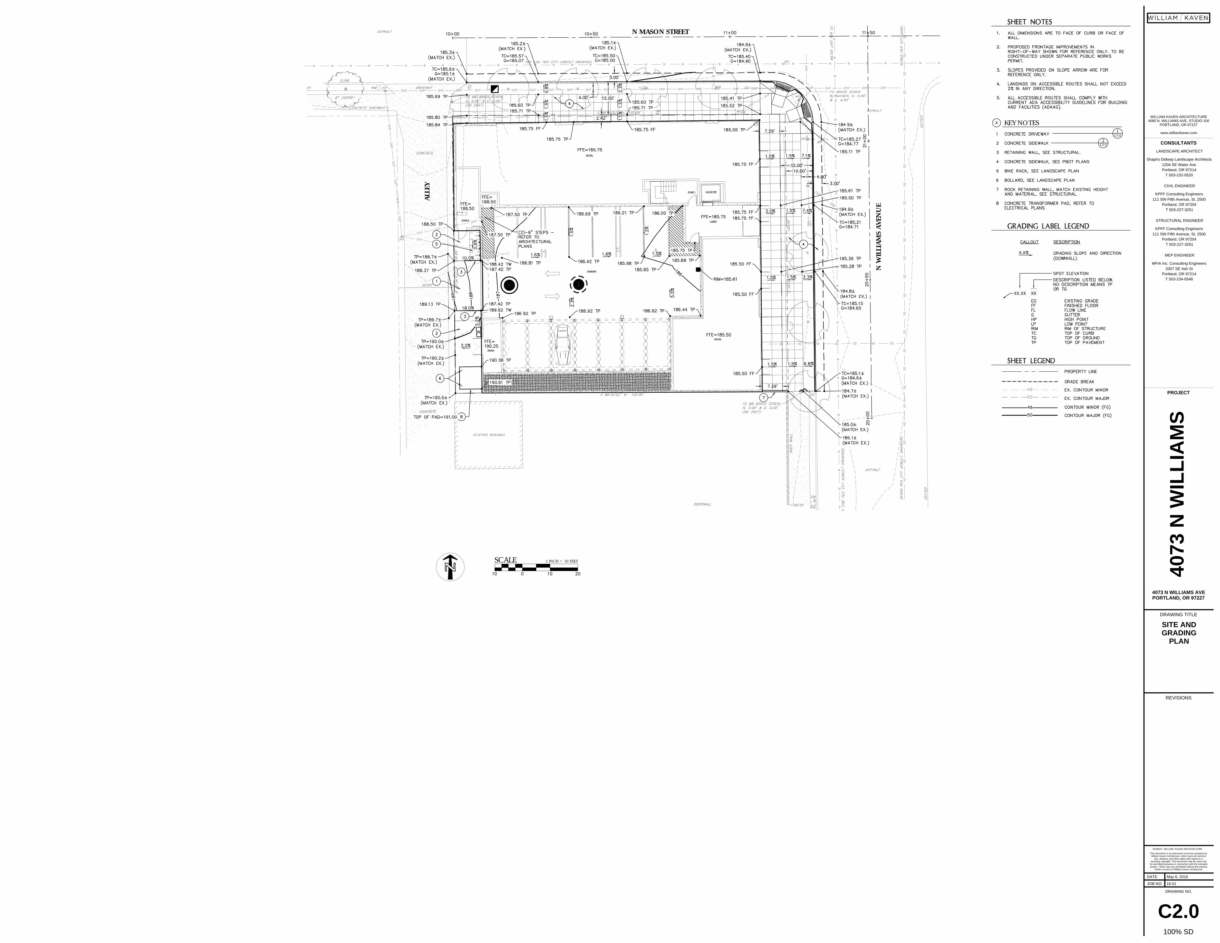
Project Overview and Description
On-Site
The project site consists of the redevelopment of the approximately 11,800 square foot lot located at the
southwest corner of the intersection of North Mason Street and North Williams Ave. The site is zoned
Central Employment (EXd). See Appendix 1, Exhibit A for the Vicinity Map and Appendix 5 for the Existing
Conditions plan sheet.
The project will consist of removing the existing building and constructing a new 4-story, mixed-use office
building. The majority of the site will be covered by the proposed structure roof with a small percentage of
that area constructed as green roof. The remaining portion of the site will consist of a retained landscape
planter and a portion of uncovered pavement adjacent to the building trash entrance.
The north and east building frontages adjoin the right-of-ways of N Mason Street and N Williams Ave,
respectively. The south property line borders the adjacent property and the west property line borders an
existing alley. Reconstruction of the N Mason Street and the N Williams Ave frontages will be included as
part of this project with the exception of the intersection curb ramp which is currently being reconstructed
by the City.
All on-site work will require a building permit from the City of Portland.
The total site area is only 11,812 square feet and therefore, a DEQ 1200c Erosion Control permit will not be
required.
Total impervious surface areas for the existing and post-redevelopment on-site area are shown below in
Table 1.
Table 1: Onsite existing and Post-Development Areas
Impervious
Surface Area
Impervious
Roof AreaGreen Roof
Total Impervious
AreaPervious Area
Total Site
Area
(sf) (sf) (sf) (sf) (sf) (sf)
Existing 1,807 10,005 - 11,812 - 11,812
Post-Development 246 10,445 700 10,691 421 11,812
Public Right-of-Way
The project’s public frontage is along the north and east face of the building on N Mason Street and N
Williams Avenue. These frontages will require full reconstruction with the addition of street trees installed
in new tree wells. The intersection curb ramps are currently being reconstructed by the City and will not be
included in our project. See Appendix 1, Exhibit B.
These improvements will require a Public Works Permit from PBOT.
5
4073 N Williams Ave | KPFF Consulting Engineers
STORMWATER DRAINAGE REPORT
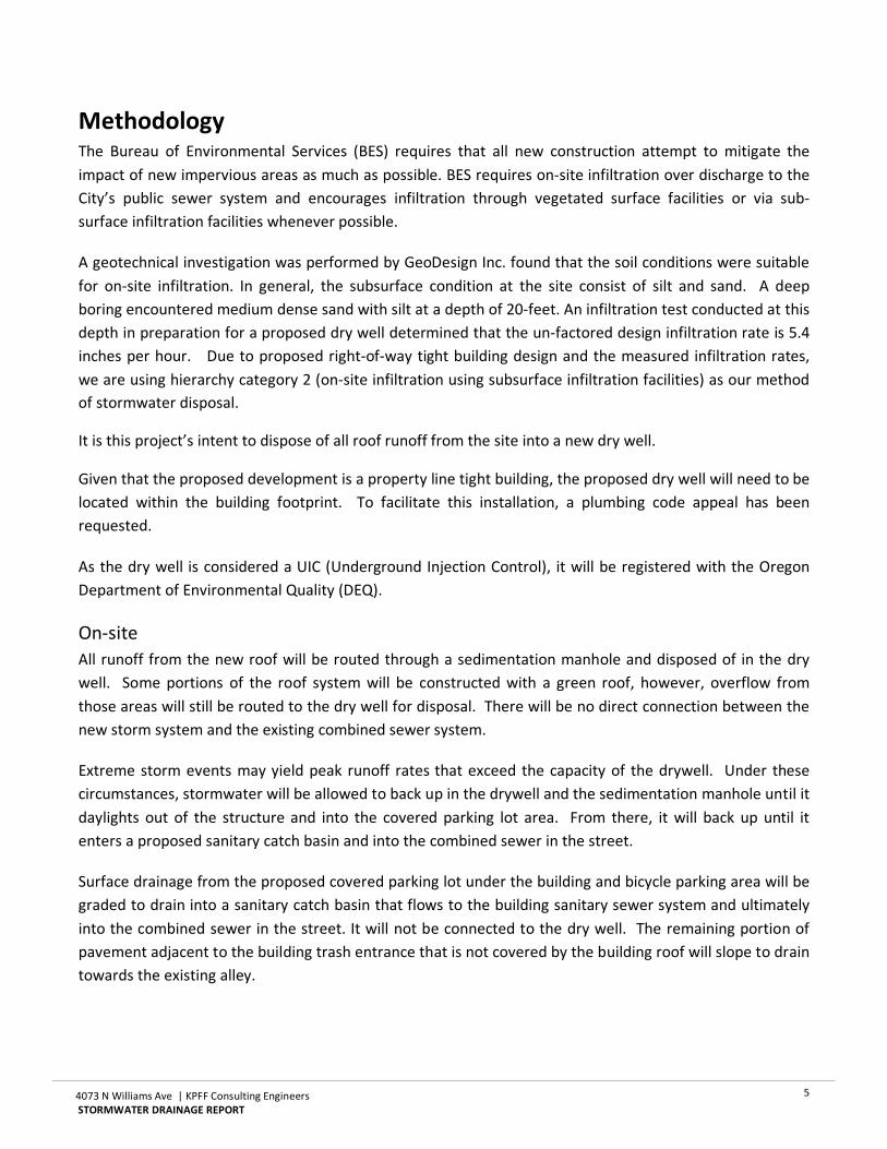
Methodology The Bureau of Environmental Services (BES) requires that all new construction attempt to mitigate the
impact of new impervious areas as much as possible. BES requires on-site infiltration over discharge to the
City’s public sewer system and encourages infiltration through vegetated surface facilities or via sub-
surface infiltration facilities whenever possible.
A geotechnical investigation was performed by GeoDesign Inc. found that the soil conditions were suitable
for on-site infiltration. In general, the subsurface condition at the site consist of silt and sand. A deep
boring encountered medium dense sand with silt at a depth of 20-feet. An infiltration test conducted at this
depth in preparation for a proposed dry well determined that the un-factored design infiltration rate is 5.4
inches per hour. Due to proposed right-of-way tight building design and the measured infiltration rates,
we are using hierarchy category 2 (on-site infiltration using subsurface infiltration facilities) as our method
of stormwater disposal.
It is this project’s intent to dispose of all roof runoff from the site into a new dry well.
Given that the proposed development is a property line tight building, the proposed dry well will need to be
located within the building footprint. To facilitate this installation, a plumbing code appeal has been
requested.
As the dry well is considered a UIC (Underground Injection Control), it will be registered with the Oregon
Department of Environmental Quality (DEQ).
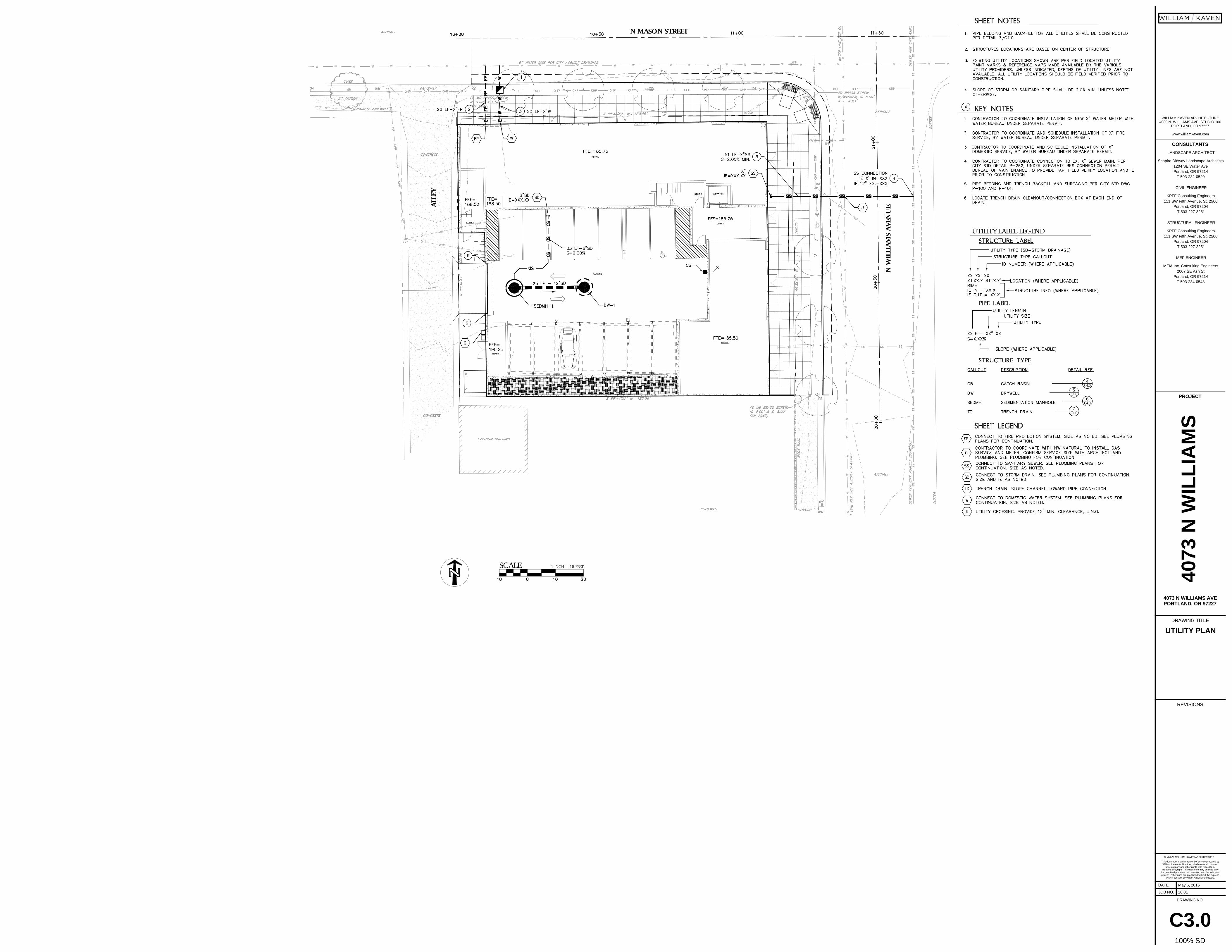
On-site
All runoff from the new roof will be routed through a sedimentation manhole and disposed of in the dry
well. Some portions of the roof system will be constructed with a green roof, however, overflow from
those areas will still be routed to the dry well for disposal. There will be no direct connection between the
new storm system and the existing combined sewer system.
Extreme storm events may yield peak runoff rates that exceed the capacity of the drywell. Under these
circumstances, stormwater will be allowed to back up in the drywell and the sedimentation manhole until it
daylights out of the structure and into the covered parking lot area. From there, it will back up until it
enters a proposed sanitary catch basin and into the combined sewer in the street.
Surface drainage from the proposed covered parking lot under the building and bicycle parking area will be
graded to drain into a sanitary catch basin that flows to the building sanitary sewer system and ultimately
into the combined sewer in the street. It will not be connected to the dry well. The remaining portion of
pavement adjacent to the building trash entrance that is not covered by the building roof will slope to drain
towards the existing alley.

6
4073 N Williams Ave | KPFF Consulting Engineers
STORMWATER DRAINAGE REPORT
Public Right-of-Way
There will be no significant change to the drainage pattern or amount of impervious area; therefore, no
stormwater improvements are required.
Analysis
Drywell Sizing
The dry well was sized based on Exhibit 2-34: Drywell Sizing Chart in Chapter 2: Facility Design of the
Stormwater Management Manual. Given the approximately 10,700 square feet of roof area, the dry well
was designed as a 48-inch diameter manhole with a depth of 20-feet.
The tributary area of the drywell is rooftop and therefore pollution reduction prior to infiltration is not
required as described in Chapter 1 of the 2014 Portland Stormwater Management Manual.
See Appendix 4a: Drywell Sizing.
Conveyance
Stormwater conveyance pipes will be sized to meet the 10-year storm event, using the Rational Method
and Manning’s Equation. See Appendix 4b: Conveyance Calculations.
Engineering Conclusions The stormwater system has been designed in accordance with the BES Stormwater Management Manual.
The proposed stormwater facilities will meet the pollution reduction and flow control requirements for new
impervious areas. The proposed facilities and components have adequate capacity to handle the required
storm events. Therefore, this preliminary stormwater system design meets the BES requirements and
should be approved as designed.

4073 N Williams Ave | KPFF Consulting Engineers
STORMWATER DRAINAGE REPORT
Appendix 1
Exhibits
A. Vicinity Map
B. Stormwater Basin Map
C. Existing Conditions Basin Map

Appendix 1A: Vicinity Map

4073 N Williams Ave | KPFF Consulting Engineers
STORMWATER DRAINAGE REPORT
This page left blank to facilitate double-sided printing

RETAIL
RETAIL
PARKING
LOBBY
ELEVATORSTAIR 1
STAIR 2
WATERRISER ROOM
TRASH
N MASON STREET
N W
ILLI
AMS
AVEN
UE
ALLE
Y
EX1B
LANDSCAPE PLANTER421 SF
NON-ROOFIMPERVIOUS AREA246 SF(SLOPES TO ALLEY)
ROOF AREA700 SF GREEN ROOF10,445 SF IMPERVIOUS
CURB RAMP IS BEINGRECONSTRUCTED BYTHE CITY.

4073 N Williams Ave | KPFF Consulting Engineers
STORMWATER DRAINAGE REPORT
Appendix 2
Exhibits
A. Geotechnical Investigation Report
B. Dry Well Review

REPORT OF GEOTECHNICAL ENGINEERING SERVICES Proposed Site Development 4073 N Williams Avenue Portland, Oregon For Ruben J. Menashe, Inc. June 24, 2016 GeoDesign Project: RJMenashe-1-01

15575 SW Sequoia Pkwy, Suite 100 l Portland, OR 97224 l 503.968.8787 www.geodesigninc.com
June 24, 2016 Ruben J. Menashe, Inc. 11359 NE Halsey Street Portland, OR 97220 Attention: Jack Menashe
Report of Geotechnical Engineering Services Proposed Site Development
4073 N Williams Avenue Portland, Oregon
GeoDesign Project: RJMenashe-1-01 GeoDesign, Inc. is pleased to submit our report of geotechnical engineering services for the proposed development located at 4073 N Williams Avenue in Portland, Oregon. Our services for this project were conducted in accordance with our confirming agreement dated June 2, 2016. We appreciate the opportunity to be of service to you. Please contact us if you have questions regarding this report. Sincerely, GeoDesign, Inc. Brett A. Shipton, P.E., G.E. Principal Engineer cc: Daniel Kaven, William/Kaven (via email only) Ryan Milkowski, KPFF Consulting Engineers (via email only) Mike Perso, William/Kaven (via email only) RSK:BAS:kt
Attachments
One copy submitted (via email only)
Document ID: RJMenashe-1-01-062416-geor.docx
© 2016 GeoDesign, Inc. All rights reserved.

i RJMenashe-1-01:062416
EXECUTIVE SUMMARY SUBSURFACE CONDITIONS We explored the subsurface conditions at the site by drilling two borings (B-1 and B-2) to depths ranging between 36.5 and 41.5 feet BGS. In general, subsurface conditions at the site consist of alluvial silt and sand to the maximum depth explored (41.5 feet BGS). The consistency and relative density of the alluvium increases with depth, with silt layers ranging from medium stiff to very stiff and sand layers ranging loose to dense. Fill was encountered in boring B-1 and extends to a depth of approximately 3 feet BGS. The fill consists of medium stiff silt with minor sand and gravel. The USGS City of Portland Depth to Groundwater Map indicates groundwater is greater than 50.0 feet BGS at the site. Infiltration testing conducted at 20.0 feet BGS had a measured unfactored infiltration rate of 5.4 inches per hour in boring B-2. CONCLUSIONS The following factors will have an impact on design and construction of the proposed development. Our specific recommendations for site development are provided in this report. The proposed structure can be supported on spread footings bearing on the underlying
native silt or on structural fill overlying firm site soil. Undocumented fill, if present, should be removed and replaced with structural fill where it is
present within foundation influence zones. The near-surface fine-grained soil is susceptible to disturbance. We recommend that
construction be staged to prevent disturbance of the subgrade from construction traffic. We recommend placing a layer of stabilization material over the subgrade that will be exposed to construction traffic to protect it during wet weather.
The on-site silty soil is at a moisture content that is above optimum and will require drying if it is to be used as structural fill.
The low plasticity silt and sandy soil is prone to raveling, and special precautions will be required to prevent undermining adjacent infrastructure if excavations are required nearby.

RJMenashe-1-01:062416
TABLE OF CONTENTS PAGE NO. 1.0 INTRODUCTION 1 2.0 PROJECT UNDERSTANDING 1 3.0 PURPOSE AND SCOPE 1 4.0 SITE CONDITIONS 2 4.1 Surface Conditions 2 4.2 Subsurface Conditions 2 4.3 Infiltration Testing 2 5.0 SITE DEVELOPMENT RECOMMENDATIONS 3 5.1 Site Preparation 3 5.2 Construction Considerations 3 5.3 Temporary Slopes 4 5.4 Permanent Slopes 4 5.5 Erosion Control 4 5.6 Structural Fill 4 6.0 FOUNDATION SUPPORT RECOMMENDATIONS 6 6.1 Spread Footings 6 7.0 SLABS ON GRADE 7 8.0 PERMANENT RETAINING STRUCTURES 8 9.0 DRAINAGE CONSIDERATIONS 8 10.0 SEISMIC DESIGN CRITERIA 8 11.0 OBSERVATION OF CONSTRUCTION 9 12.0 LIMITATIONS 9 FIGURES Vicinity Map Figure 1 Site Plan Figure 2 Surcharge-Induced Lateral Earth Pressures Figure 3 APPENDIX Field Explorations A-1 Laboratory Testing A-1 Exploration Key Table A-1 Soil Classification System Table A-2 Boring Logs Figures A-1 – A-2 Summary of Laboratory Data Figure A-3 ACRONYMS AND ABBREVIATIONS

1 RJMenashe-1-01:062416
1.0 INTRODUCTION GeoDesign, Inc. is pleased to submit this report of geotechnical engineering services for the proposed development located at 4073 N Williams Avenue in Portland, Oregon. Figure 1 shows the site relative to existing topographic and physical features. Figure 2 shows the location of the proposed development and the approximate locations of our explorations. Acronyms and abbreviations used herein are defined at the end of this document. 2.0 PROJECT UNDERSTANDING We understand that the existing structure located and other improvements at the site will be demolished. The proposed development will consist of a four-story, mixed-used structure constructed at grade. Structural loading information was not available at the time of this report. We have assumed that column loads for the new structure will be on the order of 300 to 400 kips and maximum floor slab loads of up to 150 psf. In addition, we understand that stormwater will be managed on site. We have assumed that site cuts and fills will be minimal. 3.0 PURPOSE AND SCOPE The purpose of our geotechnical services was to provide geotechnical engineering recommendations for design and construction of the proposed development. The specific scope of our services is summarized as follows: Reviewed readily available published geologic data and our in-house files for existing
information on subsurface conditions in the site vicinity. Coordinated and managed the field investigation, including locating utilities, coordination
with existing tenants, and scheduling subcontractors. Completed a subsurface exploration program that consisted of drilling two borings to depths
of up to 41.5 feet BGS. Conducted an encased falling-head infiltration test at boring B-2 at a depth of 20.0 feet BGS in general accordance with the Portland Stormwater Management Manual.
Maintained continuous logs of the explorations, and collected samples at representative intervals.
Performed a laboratory testing program consisting of the following: Ten moisture content determinations in accordance with ASTM D 2216 Four particle-size analyses in accordance with ASTM D 1140
Provided recommendations for site preparation and grading, including temporary and permanent slopes, fill placement criteria, suitability of on-site soil for fill, subgrade preparation, and recommendations for wet weather construction.
Provided foundation support recommendations for the proposed structure. Our recommendations include preferred foundation type, allowable bearing capacity, and lateral resistance parameters.
Provided recommendations for preparation of the subgrade for floor slabs. Provided recommendations for use in design of conventional retaining walls, including
backfill and drainage requirements and lateral earth pressures.

2 RJMenashe-1-01:062416
Provided seismic design recommendations in accordance with the procedures outlined in the 2012 IBC and 2014 SOSSC.
Prepared this geotechnical engineering report that presents our findings, conclusions, and recommendations.
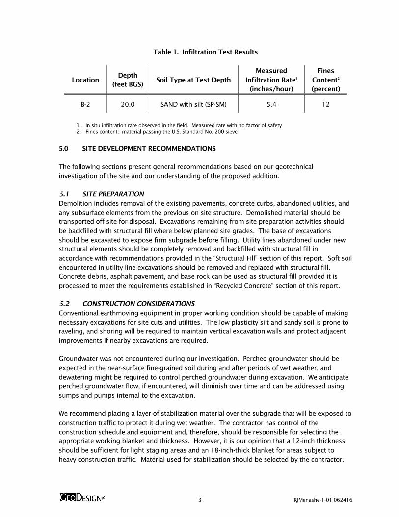
4.0 SITE CONDITIONS 4.1 SURFACE CONDITIONS The site is located southwest of the intersection of NE Mason Street and N Williams Avenue. The site encompasses an approximately 12,000-square-foot parcel and is currently developed with a one-story industrial structure. An approximate 2,500-square-foot, AC-paved parking area is located west of the structure. The surrounding vicinity is primarily developed with residential and commercial buildings. The topography of the site is generally level. 4.2 SUBSURFACE CONDITIONS 4.2.1 General We explored the subsurface conditions at the site by drilling two borings (B-1 and B-2) to depths ranging between 36.5 and 41.5 feet BGS. The approximate exploration locations are shown on Figure 2. A more detailed description of the exploration program, exploration logs, and results of laboratory testing program are presented in the Appendix. AC was present at the surface of both borings. The observed AC thickness ranges from approximately 2 to 3 inches. The aggregate base thickness beneath the AC is approximately 5 to 8 inches. In general, subsurface conditions at the site consist of alluvial silt and sand to the maximum depth explored (41.5 feet BGS). The consistency and relative density of the alluvium increases with depth, with silt layers ranging from medium stiff to very stiff and sand layers ranging from loose to dense. Fill was encountered in boring B-1 and extends to a depth of approximately 3 feet BGS. The fill consists of medium stiff silt with minor sand and gravel. Laboratory testing indicates that the encountered soil had moisture contents ranging from 9 to 29 percent at the time of our explorations. 4.2.2 Groundwater Groundwater was not encountered in our explorations to the depth explored. The USGS City of Portland Depth to Groundwater Map indicates groundwater is greater than 50.0 feet BGS at the site. Groundwater is not anticipated to have a significant impact on design and construction of the structure. 4.3 INFILTRATION TESTING An encased falling-head infiltration test was conducted at boring B-2 at a depth of 20.0 feet BGS. The infiltration test was performed in general accordance with the Portland Stormwater Management Manual. A representative soil sample was collected from below the infiltration test location for grain-size distribution analysis. The results of the field infiltration and laboratory testing are summarized in Table 1.
3 RJMenashe-1-01:062416
Table 1. Infiltration Test Results
Location Depth
(feet BGS) Soil Type at Test Depth
Measured Infiltration Rate1
(inches/hour)
Fines Content2 (percent)
B-2 20.0 SAND with silt (SP-SM) 5.4 12
1. In situ infiltration rate observed in the field. Measured rate with no factor of safety 2. Fines content: material passing the U.S. Standard No. 200 sieve
5.0 SITE DEVELOPMENT RECOMMENDATIONS The following sections present general recommendations based on our geotechnical investigation of the site and our understanding of the proposed addition. 5.1 SITE PREPARATION Demolition includes removal of the existing pavements, concrete curbs, abandoned utilities, and any subsurface elements from the previous on-site structure. Demolished material should be transported off site for disposal. Excavations remaining from site preparation activities should be backfilled with structural fill where below planned site grades. The base of excavations should be excavated to expose firm subgrade before filling. Utility lines abandoned under new structural elements should be completely removed and backfilled with structural fill in accordance with recommendations provided in the “Structural Fill” section of this report. Soft soil encountered in utility line excavations should be removed and replaced with structural fill. Concrete debris, asphalt pavement, and base rock can be used as structural fill provided it is processed to meet the requirements established in “Recycled Concrete” section of this report. 5.2 CONSTRUCTION CONSIDERATIONS Conventional earthmoving equipment in proper working condition should be capable of making necessary excavations for site cuts and utilities. The low plasticity silt and sandy soil is prone to raveling, and shoring will be required to maintain vertical excavation walls and protect adjacent improvements if nearby excavations are required. Groundwater was not encountered during our investigation. Perched groundwater should be expected in the near-surface fine-grained soil during and after periods of wet weather, and dewatering might be required to control perched groundwater during excavation. We anticipate perched groundwater flow, if encountered, will diminish over time and can be addressed using sumps and pumps internal to the excavation. We recommend placing a layer of stabilization material over the subgrade that will be exposed to construction traffic to protect it during wet weather. The contractor has control of the construction schedule and equipment and, therefore, should be responsible for selecting the appropriate working blanket and thickness. However, it is our opinion that a 12-inch thickness should be sufficient for light staging areas and an 18-inch-thick blanket for areas subject to heavy construction traffic. Material used for stabilization should be selected by the contractor.

4 RJMenashe-1-01:062416
Excavations should be made in accordance with applicable OSHA and state regulations. While this report describes certain approaches to excavation and dewatering, the contractor should be responsible for selecting excavation and dewatering methods, monitoring the excavations for safety, and providing shoring, as required to protect personnel and adjacent utilities and structures. 5.3 TEMPORARY SLOPES Construction of temporary slopes less than 10 feet high should be no steeper than 1½H:1V. If slopes greater than 10 feet high are required, GeoDesign should be contacted to make additional recommendations. All cut slopes should be protected from erosion by covering them during wet weather. If sloughing or instability is observed, the slope should be flattened or the cut supported by shoring. Excavations should not undermine adjacent utilities, foundations, walkways, streets, or other hardscapes unless special shoring or underpinned support is provided. Unsupported excavations should not be conducted within a downward and outward projection of a 1H:1V line from 2 feet outside the edge of an adjacent structural feature. 5.4 PERMANENT SLOPES Permanent cut or fill slopes should not exceed a gradient of 2H:1V, unless specifically evaluated for stability. Slopes that will be maintained by mowing should not be constructed steeper than 3H:1V. Flatter slopes may be necessary as required by the landscape designer for the project. Slopes should be planted with appropriate vegetation to provide protection against erosion as soon as possible after grading. Surface water runoff should be collected and directed away from slopes to prevent water from running down the face of the slope. 5.5 EROSION CONTROL The on-site soil is moderately susceptible to erosion. Consequently, we recommend that slopes be covered with an appropriate erosion control product if construction occurs during periods of wet weather. We recommend that all slope surfaces be planted as soon as practical to minimize erosion. Surface water runoff should be collected and directed away from slopes to prevent water from running down the slope face. Erosion control measures such as straw bales, sediment fences, and temporary detention and settling basins should be used in accordance with local and state ordinances. 5.6 STRUCTURAL FILL Structural fill includes fill beneath foundations, slabs, pavements, any other areas intended to support structures, or within the influence zones of structures. Structural fill should be free of organic matter and other deleterious material and, in general, should consist of particles no larger than 3 inches in diameter. Recommendations for suitable fill material are provided in the following sections. 5.6.1 On-Site Native Soil The on-site native soil will be suitable for use as structural fill only if it can be moisture conditioned. The on-site silty soil is sensitive to small changes in moisture content and may be difficult, if not impossible, to compact adequately during wet weather or when its moisture

5 RJMenashe-1-01:062416
content is more than a few percentage points above optimum. Laboratory tests indicate that the moisture content of the native silt unit is significantly greater than the anticipated optimum moisture content required for satisfactory compaction. Therefore, this soil may require extensive drying if it is used as structural fill. We recommend using imported granular material for structural fill if the moisture content of the on-site soil cannot be reduced. Native soil should be placed in lifts with a maximum uncompacted thickness of 8 inches and compacted to not less than 92 percent of the maximum dry density, as determined by ASTM D 1557. 5.6.2 Imported Granular Material Imported granular material should be pit- or quarry-run rock, crushed rock, or crushed gravel and sand that is fairly well graded between coarse and fine and has less than 5 percent by dry weight passing the U.S. Standard No. 200 sieve. All granular material must be durable such that there is no degradation of the material during and after installation as structural fill. The percentage of fines can be increased to 12 percent if the fill is placed during dry weather and provided the fill material is moisture conditioned, as necessary, for proper compaction. The material should be placed in lifts with a maximum uncompacted thickness of 12 inches and compacted to not less than 95 percent of the maximum dry density, as determined by ASTM D 1557. During the wet season or when wet subgrade conditions exist, the initial lift should have a maximum thickness of 15 inches and should be compacted with a smooth-drum roller without the use of vibratory action. 5.6.3 Floor Slab Base Rock Imported durable granular material placed beneath building floor slabs should be clean crushed rock or crushed gravel and sand that is fairly well graded between coarse and fine. The granular material should have a maximum particle size of 1½ inches, have less than 5 percent by dry weight passing the U.S. Standard No. 200 sieve, and have at least two mechanically fractured surfaces. The imported base rock should be placed in one lift and compacted to not less than 95 percent of the maximum dry density, as determined by ASTM D 1557. 5.6.4 Recycled Concrete Recycled concrete can be used for structural fill provided the concrete is processed to a relatively well-graded material with maximum particle size of 3 inches. This material can be used as trench backfill and general structural fill if it meets the requirements for imported granular material, which would require a smaller maximum particle size. The material should be placed in lifts with a maximum uncompacted thickness of 12 inches and compacted to not less than 95 percent of the maximum dry density, as determined by ASTM D 1557. 5.6.5 Trench Backfill Trench backfill for the utility pipe base and pipe zone should consist of durable well-graded granular material containing no organic or other deleterious material, should have a maximum particle size of ¾ inch, and should have less than 8 percent by dry weight passing the U.S. Standard No. 200 sieve. Backfill for the pipe base and to the springline of the pipe should be placed in maximum 12-inch-thick lifts and compacted to not less than 90 percent of the maximum dry density, as determined by ASTM D 1557, or as recommended by the pipe manufacturer. Backfill above the springline of

6 RJMenashe-1-01:062416
the pipe should be placed in maximum 12-inch-thick lifts and compacted to not less than 92 percent of the maximum dry density, as determined by ASTM D 1557. Trench backfill located within 2 feet of finish subgrade elevation should be placed in maximum 12-inch-thick lifts and compacted to not less than 95 percent of the maximum dry density, as determined by ASTM D 1557. 5.6.6 Stabilization Material If groundwater is present at the base of utility excavations, we recommend placing trench stabilization material at the base of the excavation consisting of at least 2 feet of well-graded gravel, crushed gravel, or crushed rock with a minimum particle size of 4 inches and less than 5 percent by dry weight passing the U.S. Standard No. 4 sieve. The material should be free of organic matter and other deleterious material and should be placed in one lift and compacted until "well keyed." 5.6.7 Drain Rock Drain rock should consist of angular, granular material with a maximum particle size of 2 inches. The material should be free of roots, organic matter, and other unsuitable materials and have less than 2 percent by dry weight passing the U.S. Standard No. 200 sieve (washed analysis). 6.0 FOUNDATION SUPPORT RECOMMENDATIONS Based on the results of our subsurface exploration program and geotechnical analysis, the planned structure may be supported by continuous wall and isolated column footings founded on the underlying native medium stiff to very stiff silt, medium dense to dense sand, or on structural fill overlying firm site soil. Our recommendations for use in foundation design and construction are provided in the following sections. 6.1 SPREAD FOOTINGS 6.1.1 Over-Excavation Variable fill and soft soil, if encountered, beneath spread footings should be removed to native competent material. The resulting excavation should be backfilled with structural fill in accordance with recommendations provided in the “Structural Fill” section of this report. Excavation should extend 6 inches beyond the footing perimeter for every foot of depth. 6.1.2 Bearing Capacity All footings should be proportioned for a maximum allowable soil bearing pressure of 3,000 psf. This bearing pressure is a net bearing pressure and applies to the total of dead and long-term live loads and may be doubled when considering seismic or wind loads. The weight of the footing and any overlying backfill can be ignored in calculating footing loads. We recommend that isolated column and continuous wall footings have minimum widths of 24 and 18 inches, respectively. The bottom of exterior footings should be founded at least

7 RJMenashe-1-01:062416
18 inches below the lowest adjacent grade. Interior footings should be founded at least 12 inches below the top of the floor slab. The recommended minimum footing depth is greater than the anticipated frost depth. We recommend that a qualified geotechnical engineer or geotechnical field technician evaluate all footing subgrades prior to construction of forms or placement of reinforcing steel and concrete. We recommend that 2 to 4 inches of compacted crushed rock be placed over the exposed subgrade to reduce disturbance to the silty subgrade soil during construction of forms and placement of reinforcing steel if construction occurs during wet weather. 6.1.3 Lateral Resistance Lateral loads can be resisted by passive earth pressure on sides of the footings and by friction on the base of the footings. We recommend a friction coefficient of 0.45 for computing the friction capacity of building foundations that bear on compacted crushed rock and 0.35 for footings bearing on the native soil. An equivalent fluid pressure of 350 pcf is recommended to compute the passive earth pressure acting on footings constructed in direct contact with compacted structural fill or native soil. This value is based on the assumptions that the adjacent confining structural fill or native soil is level and that groundwater remains below the base of the footing. The top 1 foot of soil should be neglected when calculating lateral earth pressures unless the foundation area is covered with pavement or is inside a building. The above values are not factored. 6.1.4 Settlement Shallow foundations with real bearing pressures less than 3,000 psf should experience post-construction settlement of less than 1 inch. Differential settlement of up to one-half of the total settlement magnitude can be expected between adjacent footings with similar loads. We expect that settlement will occur during construction as loads are applied. 7.0 SLABS ON GRADE A minimum 6-inch-thick layer of base rock (imported granular material) should be placed and compacted over the prepared subgrade to assist as a capillary break. The base rock should be crushed rock or crushed gravel and sand meeting the requirements outlined in the “Structural Fill” section of this report. The imported granular material should be placed in one lift and compacted to not less than 95 percent of the maximum dry density, as determined by ASTM D 1557. A subgrade modulus of 120 pci may be used to design the floor slab. Floor slab base rock should be replaced if it becomes contaminated with excessive fines (greater than 5 percent by dry weight passing the U.S. Standard No. 200 sieve). Vapor barriers are often required by flooring manufacturers to protect flooring and flooring adhesives. Many flooring manufacturers will warrant their product only if a vapor barrier is installed according to their recommendations. Selection and design of an appropriate vapor barrier (if needed) should be based on discussions among members of the design team. We can provide additional information to assist you with your decision.

8 RJMenashe-1-01:062416
8.0 PERMANENT RETAINING STRUCTURES Permanent retaining structures free to rotate slightly around the base should be designed for active earth pressures using an equivalent fluid unit pressure of 35 pcf. If retaining walls are restrained against rotation during backfilling, they should be designed for an at-rest earth pressure of 55 pcf. This value is based on the assumption that (1) the backfill is level, (2) the backfill is drained, and (3) the wall is less than 12 feet in height. Lateral pressures induced by surcharge loads can be computed using the methods presented on Figure 3. Seismic lateral forces can be calculated using a dynamic force equal to 7H2 pounds per linear foot of wall, where H is the wall height. The seismic force should be applied as a distributed load with the centroid located at 0.6H from the wall base. Footings for retaining walls should be designed as recommended for shallow foundations. Drains consisting of a perforated drainpipe wrapped in a geotextile filter should be installed behind retaining walls. The pipe should be embedded in a zone of coarse sand or gravel containing less than 2 percent by dry weight passing the U.S. Standard No. 200 sieve and should outlet to a suitable discharge. 9.0 DRAINAGE CONSIDERATIONS We recommend that roof drains be connected to a tightline leading to storm drain facilities. Pavement surfaces and open space areas should be sloped such that surface water runoff is collected and routed to suitable discharge points. We also recommend that ground surfaces adjacent to the building be sloped to facilitate positive drainage away from the building. 10.0 SEISMIC DESIGN CRITERIA Seismic design is prescribed by the 2014 SOSSC and the 2012 IBC. Table 2 presents the site design parameters prescribed by the 2012 IBC for the site.
Table 2. IBC Seismic Design Parameters
Parameter Short Period
(Ts = 0.2 second)
1 Second Period (T
1 = 1.0 second)
MCE Spectral Acceleration, S Ss = 0.97 g S
1 = 0.42 g
Site Class D
Site Coefficient, F Fa = 1.113 F
v = 1.585
Adjusted Spectral Acceleration, SM S
MS = 1.08 g S
M1 = 0.66 g
Design Spectral Response Acceleration Parameters, S
D
SDS = 0.72 g S
D1 = 0.44 g
Liquefaction settlement is the result of seismically induced densification and subsequent ground settlement of loose sand and silty sand below the groundwater table. Based on the findings of

9 RJMenashe-1-01:062416
our subsurface exploration and the anticipated groundwater elevation, it is our opinion that there is a low risk of liquefaction and liquefaction-related hazards at the site. 11.0 OBSERVATION OF CONSTRUCTION Satisfactory foundation and earthwork performance depends to a large degree on quality of construction. Sufficient observation of the contractor's activities is a key part of determining that the work is completed in accordance with the construction drawings and specifications. Subsurface conditions observed during construction should be compared with those encountered during the subsurface exploration. Recognition of changed conditions often requires experience; therefore, qualified personnel should visit the site with sufficient frequency to detect if subsurface conditions change significantly from those anticipated. We recommend that GeoDesign be retained to observe earthwork activities, including footing subgrade preparation, performing laboratory compaction and field moisture-density tests, and subgrade and base rock for floor slabs. 12.0 LIMITATIONS We have prepared this report for use by Ruben J. Menashe, Inc. and members of the design and construction teams for the proposed project. The data and report can be used for bidding or estimating purposes, but our report, conclusions, and interpretations should not be construed as warranty of the subsurface conditions and are not applicable to other nearby building sites. Exploration observations indicate soil conditions only at specific locations and only to the depths penetrated. They do not necessarily reflect soil strata or water level variations that may exist between exploration locations. If subsurface conditions differing from those described are noted during the course of excavation and construction, re-evaluation will be necessary. The site development plans and design details were preliminary at the time this report was prepared. When the design has been finalized and if there are changes in the site grades or location, configuration, design loads, or type of construction for the building and walls, the conclusions and recommendations presented may not be applicable. If design changes are made, we request that we be retained to review our conclusions and recommendations and to provide a written modification or verification.

10 RJMenashe-1-01:062416
We appreciate the opportunity to be of service to you. Please contact us if you have questions regarding this report. Sincerely, GeoDesign, Inc. Reed S. Kistler, E.I.T. Geotechnical Staff Brett A. Shipton, P.E., G.E. Principal Engineer

FIGURES

Prin
ted B
y: a
day
| P
rint
Dat
e: 6
/21
/20
16
1:5
2:1
1 P
M
Off 503.968.8787 Fax 503.968.3068
Portland OR 97224
15575 SW Sequoia Parkway - Suite 100
File
Nam
e: J:\M
-R\r
jmen
ashe\
rjm
enas
he-
1\r
jmen
ashe-
1-0
1\F
igure
s\C
AD
\RJM
enas
he-
1-0
1-V
M0
1.d
wg
| L
ayout:
FIG
UR
E 1
VICINITY MAP
PROPOSED SITE DEVELOPMENTSPORTLAND, OR
RJMENASHE-1-01
JUNE 2016 FIGURE 1
0
(SCALE IN APPROXIMATE FEET)
N
2000 4000VICINITY MAP BASED ON AERIALPHOTOGRAPH OBTAINED FROMGOOGLE EARTH PRO®
SITE

B-1
NE MASON STREET
4073 N WILLIAMSAVENUE
N W
ILLIA
MS A
VEN
UE
N V
AN
CO
UV
ER
AV
EN
UE
ALL
EY
B-2
Prin
ted B
y: a
day
| P
rint
Dat
e: 6
/24
/20
16
9:1
6:4
2 A
M
Off
50
3.9
68
.87
87
Fa
x 5
03
.96
8.3
06
8
Port
land O
R 9
72
24
15
57
5 S
W S
equoia
Par
kw
ay -
Suit
e 1
00
File
Nam
e:
J:\M
-R\R
JMen
ashe\
RJM
enas
he-
1\R
JMen
ashe-
1-0
1\F
igure
s\C
AD
\RJM
enas
he-
1-0
1-S
P01
.dw
g | L
ayout:
FIG
UR
E 2
SIT
E P
LA
N
PRO
POSE
D S
ITE
DEV
ELO
PMEN
TS
POR
TLA
ND
, O
R
RJM
ENA
SHE-
1-0
1
JUN
E 2
01
6FIG
UR
E 2
SITE PLAN BASED ON AERIAL PHOTOGRAPHOBTAINED FROM GOOGLE EARTH PRO®,MAY 19, 2016
LEGEND:
BORING
SITE BOUNDARY
0
(SCALE IN FEET)
N
50 100
B-1

FOR m<0.4=
h
LINE LOAD, Q
h = 2q ( - SIN COS 2 ) 3.14
( IN RADIANS)
h
STRIP LOAD, q
/2
L
X=mH
H
Z=nH
h
Z=nH
X=mH
POINT LOAD, Qp
H
h =QLH
0.2 n
(0.16 + n )2 2
FOR m>0.4=Q
h =(m + n )H 21.28m nL
2
2
2H
H
Q
QFOR m>0.4=
h =
FOR m<0.4=
=h
(m + n )21.77m np 2
2 3
30.28 n
(0.16 + n )p
2
2
2
2
2
X=mH
1
h h= COS (1.1 )2
STRIP LOAD PARALLEL TO WALLLINE LOAD PARALLEL TO WALL
VERTICAL POINT LOAD
DISTRIBUTION OF HORIZONTAL PRESSURES
H
NOTES:
1.
2.
THESE GUIDELINES APPLY TO RIGID WALLS WITH POISSON'S RATIO ASSUMED TO BE 0.5 FOR BACKFILL MATERIALS.
LATERAL PRESSURES FROM ANY COMBINATION OF ABOVE LOADS MAY BE DETERMINED BY THE PRINCIPLE OF SUPERPOSITION.
3. VALUES IN THIS FIGURE ARE UNFACTORED.
Off 503.968.8787 Fax 503.968.3068
Portland OR 97224
15575 SW Sequoia Parkway - Suite 100
INCESIGN SURCHARGE-INDUCED LATERAL EARTH PRESSURESRJMENASHE-1-01
FIGURE 3JUNE 2016 PROPOSED SITE DEVELOPMENTSPORTLAND, OR
Printed By: aday | Print Date: 6/21/2016 1:52:21 PMFile Name: J:\M-R\rjmenashe\rjmenashe-1\rjmenashe-1-01\Figures\CAD\RJMenashe-1-01-det01.dwg | Layout: FIGURE 3

APPENDIX

A-1 RJMenashe-1-01:062416
APPENDIX FIELD EXPLORATIONS GENERAL Subsurface conditions at the site were explored by drilling two borings (B-1 and B-2) using solid-stem auger drilling methods to depths ranging between 36.5 and 41.5 feet BGS. Drilling services were provided by Dan J. Fischer Excavating, Inc. of Forest Grove, Oregon, on May 11 and June 10, 2016. The explorations were observed by a member of our geotechnical staff. Detailed exploration logs are presented in this appendix. The locations of the explorations were determined in the field by pacing from site features. This information should be considered accurate to the degree implied by the methods used. SOIL SAMPLING Soil samples were obtained from the borings by conducting SPTs in general conformance with ASTM D 1586. The sampler was driven with a 140-pound hammer free-falling 30 inches. The number of blows required to drive the sampler 1 foot, or as otherwise indicated, into the soil is shown adjacent to the sample symbols on the exploration logs. Disturbed samples were obtained from the split barrel for subsequent classification and index testing. Sampling depths are shown on the exploration logs. We understand that calibration of the SPT used by Dan J. Fischer Excavating, Inc. has not been completed. The SPT blow counts completed by Dan J. Fischer Excavating, Inc. were conducted using two wraps around the cathead. SOIL CLASSIFICATION We obtained representative samples of the various soil encountered in the explorations for geotechnical laboratory testing. The soil samples were classified in accordance with the “Exploration Key” (Table A-1) and “Soil Classification System” (Table A-2), which are presented in this appendix. The exploration logs indicate the depths at which the soils or their characteristics change, although the change actually could be gradual. If the change occurred between sample locations, the depth was interpreted. Classifications are shown on the exploration logs. LABORATORY TESTING CLASSIFICATION The soil samples were classified in the laboratory to confirm field classifications. The laboratory classifications are shown on the exploration logs if those classifications differed from the field classifications. MOISTURE CONTENT We determined the natural moisture content of selected soil samples in general accordance with ASTM D 2216. The natural moisture content is a ratio of the weight of the water to soil in a test sample and is expressed as a percentage. The test results are presented in this appendix.

A-2 RJMenashe-1-01:062416
PARTICLE-SIZE ANALYSIS Particle-size analyses were performed on selected samples in general accordance with ASTM D 1140. This test determines of the amount of material finer than a 75-μm (No. 200) sieve expressed as a percentage of the dry weight of soil. The test results are presented in this appendix.

SYMBOL SAMPLING DESCRIPTION
Location of sample obtained in general accordance with ASTM D 1586 Standard Penetration Test with recovery Location of sample obtained using thin-wall Shelby tube or Geoprobe® sampler in general accordance with ASTM D 1587 with recovery Location of sample obtained using Dames & Moore sampler and 300-pound hammer or pushed with recovery Location of sample obtained using Dames & Moore and 140-pound hammer or pushed with recovery Location of sample obtained using 3-inch-O.D. California split-spoon sampler and 140-pound hammer Location of grab sample Rock coring interval Water level during drilling Water level taken on date shown
GEOTECHNICAL TESTING EXPLANATIONS
ATT
CBR
CON
DD
DS
HYD
MC
MD
OC
P
Atterberg Limits
California Bearing Ratio
Consolidation
Dry Density
Direct Shear
Hydrometer Gradation
Moisture Content
Moisture-Density Relationship
Organic Content
Pushed Sample
PP
P200
RES
SIEV
TOR
UC
VS
kPa
Pocket Penetrometer
Percent Passing U.S. Standard No. 200 Sieve
Resilient Modulus
Sieve Gradation
Torvane
Unconfined Compressive Strength
Vane Shear
Kilopascal
ENVIRONMENTAL TESTING EXPLANATIONS
CA
P
PID
ppm
Sample Submitted for Chemical Analysis
Pushed Sample
Photoionization Detector Headspace Analysis
Parts per Million
ND
NS
SS
MS
HS
Not Detected
No Visible Sheen
Slight Sheen
Moderate Sheen
Heavy Sheen
15575 SW Sequoia Parkway - Suite 100
Portland OR 97224 Off 503.968.8787 Fax 503.968.3068
EXPLORATION KEY TABLE A-1
Graphic Log of Soil and Rock Types
Inferred contact between soil or rock units (at approximate depths indicated)
Observed contact between soil or rock units (at depth indicated)

RELATIVE DENSITY - COARSE-GRAINED SOILS
Relative Density Standard Penetration
Resistance Dames & Moore Sampler
(140-pound hammer) Dames & Moore Sampler
(300-pound hammer)
Very Loose 0 – 4 0 - 11 0 - 4
Loose 4 – 10 11 - 26 4 - 10
Medium Dense 10 – 30 26 - 74 10 - 30
Dense 30 – 50 74 - 120 30 - 47
Very Dense More than 50 More than 120 More than 47
CONSISTENCY - FINE-GRAINED SOILS
Consistency Standard Penetration
Resistance Dames & Moore Sampler
(140-pound hammer) Dames & Moore Sampler
(300-pound hammer) Unconfined Compressive
Strength (tsf)
Very Soft Less than 2 Less than 3 Less than 2 Less than 0.25
Soft 2 - 4 3 – 6 2 - 5 0.25 - 0.50
Medium Stiff 4 - 8 6 – 12 5 - 9 0.50 - 1.0
Stiff 8 - 15 12 – 25 9 - 19 1.0 - 2.0
Very Stiff 15 - 30 25 – 65 19 – 31 2.0 - 4.0
Hard More than 30 More than 65 More than 31 More than 4.0
PRIMARY SOIL DIVISIONS GROUP SYMBOL GROUP NAME
COARSE-GRAINED SOILS
(more than 50%
retained on No. 200 sieve)
GRAVEL
(more than 50% of coarse fraction
retained on No. 4 sieve)
CLEAN GRAVELS (< 5% fines)
GW or GP GRAVEL
GRAVEL WITH FINES (≥ 5% and ≤ 12% fines)
GW-GM or GP-GM GRAVEL with silt
GW-GC or GP-GC GRAVEL with clay
GRAVELS WITH FINES (> 12% fines)
GM silty GRAVEL
GC clayey GRAVEL
GC-GM silty, clayey GRAVEL
SAND
(50% or more of coarse fraction
passing No. 4 sieve)
CLEAN SANDS (<5% fines)
SW or SP SAND
SANDS WITH FINES (≥ 5% and ≤ 12% fines)
SW-SM or SP-SM SAND with silt
SW-SC or SP-SC SAND with clay
SANDS WITH FINES (> 12% fines)
SM silty SAND
SC clayey SAND
SC-SM silty, clayey SAND
FINE-GRAINED SOILS
(50% or more
passing No. 200 sieve)
SILT AND CLAY
Liquid limit less than 50
ML SILT
CL CLAY
CL-ML silty CLAY
OL ORGANIC SILT or ORGANIC CLAY
Liquid limit 50 or greater
MH SILT
CH CLAY
OH ORGANIC SILT or ORGANIC CLAY
HIGHLY ORGANIC SOILS PT PEAT
MOISTURE CLASSIFICATION
ADDITIONAL CONSTITUENTS
Term Field Test
Secondary granular components or other materials such as organics, man-made debris, etc.
Percent
Silt and Clay In:
Percent
Sand and Gravel In:
dry very low moisture, dry to touch
Fine-Grained Soils
Coarse-Grained Soils
Fine-Grained Soils
Coarse-Grained Soils
moist damp, without visible moisture
< 5 trace trace < 5 trace trace
5 – 12 minor with 5 – 15 minor minor
wet visible free water, usually saturated
> 12 some silty/clayey 15 – 30 with with
> 30 sandy/gravelly Indicate %
15575 SW Sequoia Parkway - Suite 100
Portland OR 97224 Off 503.968.8787 Fax 503.968.3068
SOIL CLASSIFICATION SYSTEM TABLE A-2
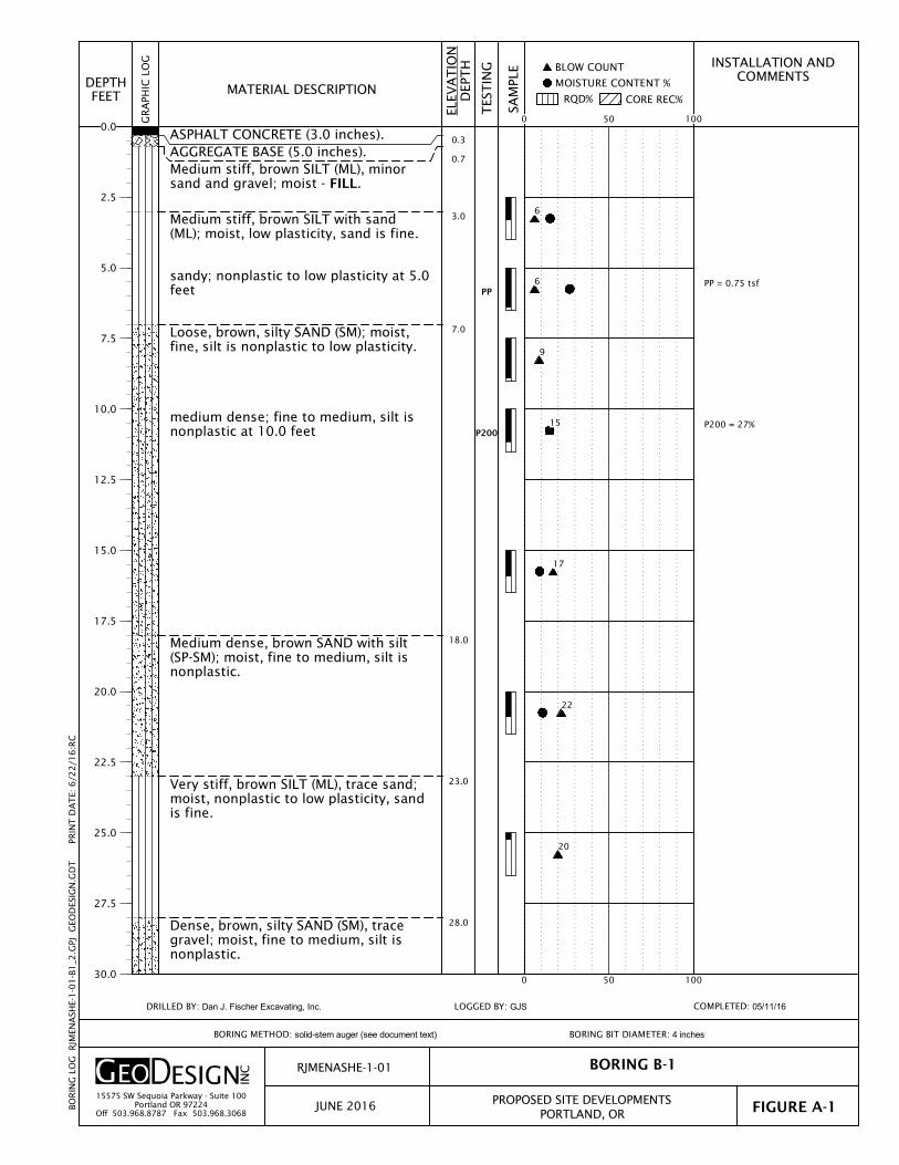
PP = 0.75 tsf
P200 = 27%
0.3
0.7
3.0
7.0
18.0
23.0
28.0
PP
P200
ASPHALT CONCRETE (3.0 inches).AGGREGATE BASE (5.0 inches).Medium stiff, brown SILT (ML), minorsand and gravel; moist - FILL.
Medium stiff, brown SILT with sand(ML); moist, low plasticity, sand is fine.
sandy; nonplastic to low plasticity at 5.0feet
Loose, brown, silty SAND (SM); moist,fine, silt is nonplastic to low plasticity.
medium dense; fine to medium, silt isnonplastic at 10.0 feet
Medium dense, brown SAND with silt(SP-SM); moist, fine to medium, silt isnonplastic.
Very stiff, brown SILT (ML), trace sand;moist, nonplastic to low plasticity, sandis fine.
Dense, brown, silty SAND (SM), tracegravel; moist, fine to medium, silt isnonplastic.
INSTALLATION ANDCOMMENTS
MOISTURE CONTENT %
CORE REC%RQD%
BLOW COUNT
BORING B-1
COMPLETED: 05/11/16
ELEV
AT
ION
DEP
TH
SAM
PLE
FIGURE A-1
BORING BIT DIAMETER: 4 inches
PORTLAND, OR
RJMENASHE-1-01
PROPOSED SITE DEVELOPMENTS
GR
APH
IC L
OG
MATERIAL DESCRIPTION
TES
TIN
G
DEPTHFEET
LOGGED BY: GJS
JUNE 201615575 SW Sequoia Parkway - Suite 100
Portland OR 97224Off 503.968.8787 Fax 503.968.3068
BORING METHOD: solid-stem auger (see document text)
DRILLED BY: Dan J. Fischer Excavating, Inc.
BO
RIN
G L
OG
R
JMEN
ASH
E-1
-01
-B1
_2.G
PJ
GEO
DES
IGN
.GD
T
PRIN
T D
AT
E: 6
/22
/16
:RC
0 50 100
0 50 100
0.0
2.5
5.0
7.5
10.0
12.5
15.0
17.5
20.0
22.5
25.0
27.5
30.0
6
6
9
15
17
22
20
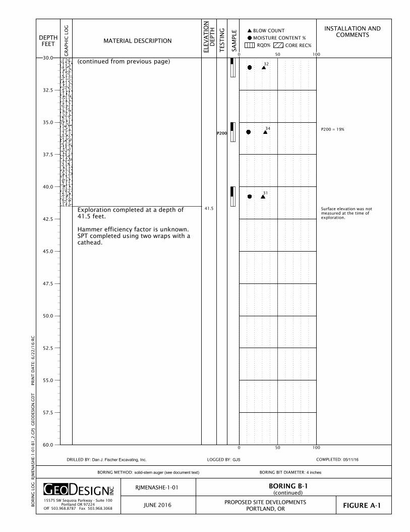
P200 = 19%
Surface elevation was notmeasured at the time ofexploration.
41.5
P200
(continued from previous page)
Exploration completed at a depth of41.5 feet.
Hammer efficiency factor is unknown.SPT completed using two wraps with acathead.
INSTALLATION ANDCOMMENTS
MOISTURE CONTENT %
CORE REC%RQD%
BLOW COUNT
BORING B-1
COMPLETED: 05/11/16
ELEV
AT
ION
DEP
TH
SAM
PLE
FIGURE A-1
BORING BIT DIAMETER: 4 inches
PORTLAND, OR
RJMENASHE-1-01
PROPOSED SITE DEVELOPMENTS
GR
APH
IC L
OG
MATERIAL DESCRIPTION
TES
TIN
G
(continued)
DEPTHFEET
LOGGED BY: GJS
JUNE 201615575 SW Sequoia Parkway - Suite 100
Portland OR 97224Off 503.968.8787 Fax 503.968.3068
BORING METHOD: solid-stem auger (see document text)
DRILLED BY: Dan J. Fischer Excavating, Inc.
BO
RIN
G L
OG
R
JMEN
ASH
E-1
-01
-B1
_2.G
PJ
GEO
DES
IGN
.GD
T
PRIN
T D
AT
E: 6
/22
/16
:RC
0 50 100
0 50 100
30.0
32.5
35.0
37.5
40.0
42.5
45.0
47.5
50.0
52.5
55.0
57.5
60.0
32
34
31

P200 = 45%
Infiltration test at 20.0 feet.P200 = 12%
0.1
0.9
7.5
15.0
P200
P200
ASPHALT CONCRETE (1.8 inches).AGGREGATE BASE (8.3 inches).Medium stiff, light brown-orange SILTwith sand (ML); moist.
grades to stiff; stratified beds of siltySAND (~4 inches thick) at 5.0 feet
Medium dense, light brown, silty SAND(SM); moist, fine, stratified beds of SILT(up to 1 1/2 inches observed onlyonce).
Medium dense, brown to gray SANDwith silt (SP-SM); moist, fine andmedium, laminated beds of silt.
INSTALLATION ANDCOMMENTS
MOISTURE CONTENT %
CORE REC%RQD%
BLOW COUNT
BORING B-2
COMPLETED: 06/10/16
ELEV
AT
ION
DEP
TH
SAM
PLE
FIGURE A-2
BORING BIT DIAMETER: 4 inches
PORTLAND, OR
RJMENASHE-1-01
PROPOSED SITE DEVELOPMENTS
GR
APH
IC L
OG
MATERIAL DESCRIPTION
TES
TIN
G
DEPTHFEET
LOGGED BY: JGH
JUNE 201615575 SW Sequoia Parkway - Suite 100
Portland OR 97224Off 503.968.8787 Fax 503.968.3068
BORING METHOD: solid-stem auger (see document text)
DRILLED BY: Dan J. Fischer Excavating, Inc.
BO
RIN
G L
OG
R
JMEN
ASH
E-1
-01
-B1
_2.G
PJ
GEO
DES
IGN
.GD
T
PRIN
T D
AT
E: 6
/22
/16
:RC
0 50 100
0 50 100
0.0
2.5
5.0
7.5
10.0
12.5
15.0
17.5
20.0
22.5
25.0
27.5
30.0
7
10
16
15
21
40
25

Surface elevation was notmeasured at the time ofexploration.
30.0
35.0
36.5
Medium dense, light brown, silty SAND(SM); moist, fine, stratified beds of SILT(up to 1 inch thick).wet at 31.0 feet
Dense, light brown-light gray SAND withsilt (SP-SM); moist, fine.
Exploration completed at a depth of36.5 feet.
Hammer efficiency factor is unknown.SPT completed using two wraps with acathead.
INSTALLATION ANDCOMMENTS
MOISTURE CONTENT %
CORE REC%RQD%
BLOW COUNT
BORING B-2
COMPLETED: 06/10/16
ELEV
AT
ION
DEP
TH
SAM
PLE
FIGURE A-2
BORING BIT DIAMETER: 4 inches
PORTLAND, OR
RJMENASHE-1-01
PROPOSED SITE DEVELOPMENTS
GR
APH
IC L
OG
MATERIAL DESCRIPTION
TES
TIN
G
(continued)
DEPTHFEET
LOGGED BY: JGH
JUNE 201615575 SW Sequoia Parkway - Suite 100
Portland OR 97224Off 503.968.8787 Fax 503.968.3068
BORING METHOD: solid-stem auger (see document text)
DRILLED BY: Dan J. Fischer Excavating, Inc.
BO
RIN
G L
OG
R
JMEN
ASH
E-1
-01
-B1
_2.G
PJ
GEO
DES
IGN
.GD
T
PRIN
T D
AT
E: 6
/22
/16
:RC
0 50 100
0 50 100
30.0
32.5
35.0
37.5
40.0
42.5
45.0
47.5
50.0
52.5
55.0
57.5
60.0
17
31

B-1 2.5 15
B-1 5.0 27
B-1 10.0 15 27
B-1 15.0 9
B-1 20.0 11
B-1 30.0 14
B-1 35.0 12 19
B-1 40.0 14
B-2 2.5 27
B-2 5.0 29
B-2 7.5 22 45
B-2 10.0 17
B-2 15.0 10
B-2 20.0 10 12
GRAVEL(PERCENT)
SAMPLEDEPTH(FEET)
SUMMARY OF LABORATORY DATA
ELEVATION(FEET)
P200(PERCENT)
SIEVE
PLASTICLIMIT
PLASTICITYINDEX
ATTERBERG LIMITSMOISTURECONTENT(PERCENT)
SAMPLE INFORMATION
EXPLORATIONNUMBER
SAND(PERCENT)
DRYDENSITY
(PCF)LIQUIDLIMIT
RJMENASHE-1-01
JUNE 2016 PROPOSED SITE DEVELOPMENTSPORTLAND, OR FIGURE A-3
15575 SW Sequoia Parkway - Suite 100Portland OR 97224
Off 503.968.8787 Fax 503.968.3068
LAB S
UM
MA
RY
RJM
ENA
SHE-
1-0
1-B
1_2
.GPJ
G
EOD
ESIG
N.G
DT
PR
INT
DA
TE:
6/2
2/1
6:R
C

ACRONYMS AND ABBREVIATIONS

RJMenashe-1-01:062416
ACRONYMS AND ABBREVIATIONS AC asphalt concrete ASTM American Society for Testing and Materials BGS below ground surface g gravitational acceleration (32.2 feet/second2) H:V horizontal to vertical IBC International Building Code MCE maximum considered earthquake OSHA Occupational Safety and Health Administration pcf pounds per cubic foot pci pounds per cubic inch psf pounds per square foot SOSSC State of Oregon Structural Specialty Code SPT standard penetration test μm micrometer USGS U.S. Geological Survey


4073 N Williams Ave | KPFF Consulting Engineers
STORMWATER DRAINAGE REPORT
Appendix 3
Assumptions
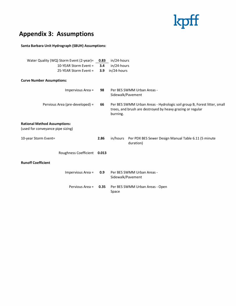
Appendix 3: Assumptions
Santa Barbara Unit Hydrograph (SBUH) Assumptions:
Water Quality (WQ) Storm Event (2-year)= 0.83 in/24-hours
10-YEAR Storm Event = 3.4 in/24-hours
25-YEAR Storm Event = 3.9 in/24-hours
Curve Number Assumptions:
Impervious Area = 98 Per BES SWMM Urban Areas -
Sidewalk/Pavement
Pervious Area (pre-developed) = 66 Per BES SWMM Urban Areas - Hydrologic soil group B, Forest litter, small
trees, and brush are destroyed by heavy grazing or regular
burning.
Rational Method Assumptions:
(used for conveyance pipe sizing)
10-year Storm Event= 2.86 in/hours Per PDX BES Sewer Design Manual Table 6.11 (5 minute
duration)
Roughness Coefficient 0.013
Runoff Coefficient
Impervious Area = 0.9 Per BES SWMM Urban Areas -
Sidewalk/Pavement
Pervious Area = 0.35 Per BES SWMM Urban Areas - Open
Space

4073 N Williams Ave | KPFF Consulting Engineers
STORMWATER DRAINAGE REPORT
Appendix 4a
Dry Well Sizing

Appendix 4a: Dry Well Sizing

4073 N Williams Ave | KPFF Consulting Engineers
STORMWATER DRAINAGE REPORT
Appendix 4b
Conveyance Calculations

4073 N Williams Avenue
Conveyance
KPFF Consulting Engineers
25-year
SBUH
Intensity Area Runoff Flow Capacity Velocity Runoff Velocity
PIPE CONTRIBUTING C I A Q Slope Diameter Qf Vf Ratio at Capacity
BASIN/PIPE (in/hr) (sf) (cfs) (%) (in) (cfs) ft/s Q/Qf Q/Qf Q vs. Qf
Roof Drain Roof 0.90 2.86 11,145 0.66 1.0 8.0 1.21 3.46 0.54 3.53 OK*
* Meets required size using the Rational Method and Manning’s Equation for 10-year event.
Storm Conveyance Calculations
10-Year Storm DESIGN
DESIGN SECTION Rational Method Calculations Manning's Calculations
20160628-CALC-NW.xls Page 1 of 1 7/13/2016

4073 N Williams Ave | KPFF Consulting Engineers
STORMWATER DRAINAGE REPORT
Appendix 5
On-site Plans

REVISIONS
This document is an instrument of service prepared by
William Kaven Architecture, which owns all common
law, statutory and other rights with regard to it,
including copyright. This document may be used only
for permitted purposes in connection with the indicated
project. Other uses are prohibited without the express
written consent of William Kaven Architecture.
JOB NO.
© MMXV WILLIAM KAVEN ARCHITECTURE
PROJECT
CONSULTANTS
CIVIL ENGINEER
KPFF Consulting Engineers
111 SW Fifth Avenue, St. 2500
Portland, OR 97204
T 503-227-3251
MEP ENGINEER
MFIA Inc. Consulting Engineers
2007 SE Ash St
Portland, OR 97214
T 503-234-0548
DRAWING NO.
DATE
DRAWING TITLE
WILLIAM KAVEN ARCHITECTURE
4080 N. WILLIAMS AVE, STUDIO 100
PORTLAND, OR 97227
www.williamkaven.com
STRUCTURAL ENGINEER
KPFF Consulting Engineers
111 SW Fifth Avenue, St. 2500
Portland, OR 97204
T 503-227-3251
LANDSCAPE ARCHITECT
Shapiro Didway Landscape Architects
1204 SE Water Ave
Portland, OR 97214
T 503-232-0520
4073 N WILLIAMS AVE
PORTLAND, OR 97227
16.01
40
73
N
W
IL
LIA
MS
100% SD
May 6, 2016
N MASON STREET
N W
ILLI
AMS
AVEN
UE
ALLE
Y
C1.0
DEMO PLAN
SCALE 1 INCH = 10 FEET
RETAIL
RETAIL
PARKING
LOBBY
ELEVATOR
STAIR 1
STAIR 2
WATER
RISER ROOM
TRASH
REVISIONS
This document is an instrument of service prepared by
William Kaven Architecture, which owns all common
law, statutory and other rights with regard to it,
including copyright. This document may be used only
for permitted purposes in connection with the indicated
project. Other uses are prohibited without the express
written consent of William Kaven Architecture.
JOB NO.
© MMXV WILLIAM KAVEN ARCHITECTURE
PROJECT
CONSULTANTS
CIVIL ENGINEER
KPFF Consulting Engineers
111 SW Fifth Avenue, St. 2500
Portland, OR 97204
T 503-227-3251
MEP ENGINEER
MFIA Inc. Consulting Engineers
2007 SE Ash St
Portland, OR 97214
T 503-234-0548
DRAWING NO.
DATE
DRAWING TITLE
WILLIAM KAVEN ARCHITECTURE
4080 N. WILLIAMS AVE, STUDIO 100
PORTLAND, OR 97227
www.williamkaven.com
STRUCTURAL ENGINEER
KPFF Consulting Engineers
111 SW Fifth Avenue, St. 2500
Portland, OR 97204
T 503-227-3251
LANDSCAPE ARCHITECT
Shapiro Didway Landscape Architects
1204 SE Water Ave
Portland, OR 97214
T 503-232-0520
4073 N WILLIAMS AVE
PORTLAND, OR 97227
16.01
40
73
N
W
IL
LIA
MS
100% SD
May 6, 2016
N MASON STREET
N W
ILLI
AMS
AVEN
UE
ALLE
Y
SCALE 1 INCH = 10 FEET
KEY NOTES
2C4.0
1C4.0
C2.0
SITE AND
GRADING
PLAN
RETAIL
RETAIL
PARKING
LOBBY
ELEVATOR
STAIR 1
STAIR 2
WATER
RISER ROOM
TRASH
N MASON STREET
N W
ILLI
AMS
AVEN
UEAL
LEY
SCALE 1 INCH = 10 FEET
UTILITY LABEL LEGEND
4C4.0
5C4.0
6C4.0
7C4.0
REVISIONS
This document is an instrument of service prepared by
William Kaven Architecture, which owns all common
law, statutory and other rights with regard to it,
including copyright. This document may be used only
for permitted purposes in connection with the indicated
project. Other uses are prohibited without the express
written consent of William Kaven Architecture.
JOB NO.
© MMXV WILLIAM KAVEN ARCHITECTURE
PROJECT
CONSULTANTS
CIVIL ENGINEER
KPFF Consulting Engineers
111 SW Fifth Avenue, St. 2500
Portland, OR 97204
T 503-227-3251
MEP ENGINEER
MFIA Inc. Consulting Engineers
2007 SE Ash St
Portland, OR 97214
T 503-234-0548
DRAWING NO.
DATE
DRAWING TITLE
WILLIAM KAVEN ARCHITECTURE
4080 N. WILLIAMS AVE, STUDIO 100
PORTLAND, OR 97227
www.williamkaven.com
STRUCTURAL ENGINEER
KPFF Consulting Engineers
111 SW Fifth Avenue, St. 2500
Portland, OR 97204
T 503-227-3251
LANDSCAPE ARCHITECT
Shapiro Didway Landscape Architects
1204 SE Water Ave
Portland, OR 97214
T 503-232-0520
4073 N WILLIAMS AVE
PORTLAND, OR 97227
16.01
40
73
N
W
IL
LIA
MS
100% SD
May 6, 2016
C3.0
UTILITY PLAN

REVISIONS
This document is an instrument of service prepared by
William Kaven Architecture, which owns all common
law, statutory and other rights with regard to it,
including copyright. This document may be used only
for permitted purposes in connection with the indicated
project. Other uses are prohibited without the express
written consent of William Kaven Architecture.
JOB NO.
© MMXV WILLIAM KAVEN ARCHITECTURE
PROJECT
CONSULTANTS
CIVIL ENGINEER
KPFF Consulting Engineers
111 SW Fifth Avenue, St. 2500
Portland, OR 97204
T 503-227-3251
MEP ENGINEER
MFIA Inc. Consulting Engineers
2007 SE Ash St
Portland, OR 97214
T 503-234-0548
DRAWING NO.
DATE
DRAWING TITLE
WILLIAM KAVEN ARCHITECTURE
4080 N. WILLIAMS AVE, STUDIO 100
PORTLAND, OR 97227
www.williamkaven.com
STRUCTURAL ENGINEER
KPFF Consulting Engineers
111 SW Fifth Avenue, St. 2500
Portland, OR 97204
T 503-227-3251
LANDSCAPE ARCHITECT
Shapiro Didway Landscape Architects
1204 SE Water Ave
Portland, OR 97214
T 503-232-0520
4073 N WILLIAMS AVE
PORTLAND, OR 97227
16.01
40
73
N
W
IL
LIA
MS
100% SD
May 6, 2016
UNPAVEDAREAS
PAVEDAREAS
SECTION 'B'
PLAN
SECTION
SECTION
C4.0
DETAILS

4073 N Williams Ave | KPFF Consulting Engineers
STORMWATER DRAINAGE REPORT
Appendix 6
Stormwater Operations & Maintenance Plan

111 SW Fifth Avenue, Suite 2500 Portland, OR 97204 503.542.3860 kpff.com
4073 N Williams Ave | KPFF Consulting Engineers
OPERATIONS & MAINTENANCE MANUAL
Onsite Stormwater System
Operations & Maintenance Plan
for
4073 N Williams Ave, Portland, OR
In order for the stormwater treatment facilities to continue operating at acceptable levels, regular
maintenance and inspection are required. This plan provides maintenance and inspection instructions.
The Operations and Maintenance Plan shall be recorded with Multnomah County.
Project Engineer: Ryan Milkowski, PE
KPFF Consulting Engineers
111 SW 5th Avenue, Suite 2500
Portland, OR 97204
Date: July 2016
KPFF Project No. 1600036

1
4073 N Williams Ave | KPFF Consulting Engineers
OPERATIONS & MAINTENANCE MANUAL
A. RESPONSIBILITY .......................................................................................................................................................... 2
B. DESCRIPTION ............................................................................................................................................................... 2
DEFINITIONS ..................................................................................................................................................................... 2
C. SCHEDULE .................................................................................................................................................................... 2
D. PROCEDURE ................................................................................................................................................................. 2
DRY WELL ........................................................................................................................................................................ 3
SEDIMENTATION MANHOLE ................................................................................................................................................. 3
GREEN ROOF .................................................................................................................................................................... 3
TRAPPED AREA DRAINS AND PIPED STORM SYSTEM ............................................................................................................. 3
E. INSPECTION AND MAINTENANCE LOGS ................................................................................................................... 5
F. SAMPLE O&M LOG SHEET ............................................................................................................................................. 6
G. O&M LOG SHEET ......................................................................................................................................................... 7
H. APPENDIX: EXHIBITS ................................................................................................................................................... 8
EXHIBIT A: PROPOSED ONSITE SYSTEM .............................................................................................................................. 8

2
4073 N Williams Ave | KPFF Consulting Engineers
OPERATIONS & MAINTENANCE MANUAL
A. Responsibility It is the responsibility of the owner to maintain the stormwater system to ensure proper functioning of the
system. The preparer has designed a system that can be easily maintained by maintenance staff.
A copy of the Operations and Maintenance (O&M) Plan shall be provided to all property owners and kept
onsite with access to it by maintenance staff.
B. Description The stormwater system collects and filters runoff from impervious areas within the site as required by the
City of Portland.
Runoff from the proposed building roof will be piped to drain into a sedimentation manhole prior to
disposal in a dry well located within the building footprint.
Facility Type Facility
Depth
Drainage
is from:
Impervious
Area
treated (sf)
Discharge Point
DW-1 Dry Well 20 Roof 11,145 On-Site
Definitions
• Dry Well: An open bottom, underground concrete structure with perforated sides designed to allow
runoff to infiltrate into the surround soil.
• Green Roof: A roofing system consisting of a layer of vegetation over a growing medium on top of a
synthetic waterproof membrane.
• Sedimentation Manhole: A concrete manhole structure with a 4-foot sump and hooded outlet pipe
designed to capture sediment and debris out of the runoff prior to disposal in a dry well.
C. Schedule The whole system shall be inspected and maintained quarterly and within 48 hours after each major storm
event. For this Operations & Maintenance Plan, a major storm event is defined as 1.0-inch of rain or more
in 24 hours. All components of the storm system as described below must be inspected and maintained
frequently or they will cease to function effectively. The facility owner must keep a log recording all
inspection dates, observations and maintenance activities. Receipts shall be saved when maintenance is
performed and there is record of expense.
D. Procedure The following items shall be inspected and maintained as stated:

3
4073 N Williams Ave | KPFF Consulting Engineers
OPERATIONS & MAINTENANCE MANUAL
Dry Well
• The drywell shall infiltrate and discharge stormwater within 48 hours of a storm event.
• Shall be inspected a minimum of quarterly for clogging.
• Shall be inspected for cracks or leaks during each inspection. Repair with grout or City-approved
material.
Sedimentation Manhole
• Shall be inspected a minimum of quarterly for clogging.
• Shall be inspected for cracks or leaks during each inspection. Repair with grout or City-approved
material.
• Clean out and remove sediment, oil, and debris when sediment is at 30% of capacity or oil is 2 inches
deep or a minimum of once per year. Clean out shall be done in a manner to minimize the amount of
sediment and trapped oil entering the outlet pipe. The outlet should be plugged prior to clean out.
• Water, oil and sediment in the separating chamber shall be removed and disposed of in accordance
with federal and state regulations. Grit and sediment that has settled to the bottom of the manhole
shall be removed during each cleaning.
• Cleaning shall be done without use of detergents or surfactants. A pressure washer may be used if
necessary.
Green Roof
• Clogged drains shall be cleared of sediment and debris.
• Tears or perforations of the membrane shall be repair or replace per manufacturer.
• Vegetation shall cover 90% of the facility. Remove dead or stressed vegetation and replant per original
planting plan.
• Irrigate and mulch as needed to prevent dry grass or other plants.
• Prune tall, dry grasses and remove clippings.
• Manually remove weeds. Do not use pesticides.
• Cover exposed soil with plants and mulch as needed.
• Fill, hand tamp or lightly compact eroded soil and gullies. Plant vegetation to disperse flow.
• Rake or amend crusting, dry, or shrinking medium material.
Trapped Area Drains and Piped Storm System
• Shall be inspected quarterly for clogging.
• Shall be inspected for cracks or leaks during each inspection. The trapped area drains and trench drains
shall be cleaned out at a minimum of once per year or more frequently if inspections deem it necessary.
Cleanout shall be done in a manner to minimize the amount of sediment and trapped oil entering the
outlet pipe. If there is a valve on the outlet pipe it shall be closed. Otherwise, the outlet should be
plugged prior to clean out.
• Debris shall be removed from inlets quarterly.
• Water, oil and sediment in the separating chamber shall be removed and disposed of in accordance
with federal and state regulations. Grit and sediment that has settled to the bottom of the manhole
shall be removed during each cleaning.

4
4073 N Williams Ave | KPFF Consulting Engineers
OPERATIONS & MAINTENANCE MANUAL
• Cleaning shall be done without use of detergents or surfactants. A pressure washer may be used if
necessary.
Spill Prevention measures shall be exercised when handling substances that can contaminate stormwater.
It is important to exercise caution when handling substances that can contaminate stormwater. Activities
that pose the chance of hazardous material spills shall not take place near collection facilities.
• Contact facility owner immediately if spill is observed.
• Releases of pollutants shall be corrected as soon as identified.
Insects & Rodents shall not be harbored in the any part of the storm system.
• Pest control measures shall be taken when insects/rodents are found to be present.
• If sprays are considered, a mosquito larvicide, such as Bacillus thurendensis or Altoside formulations,
can be applied only if absolutely necessary and shall not be used where it will enter groundwater or
come in contact with any standing water. Sprays shall be applied only by a licensed individual or
contractor.
• Holes in the ground located in and around the storm system shall be filled.
• Outfalls draining into flow-through planter shall be inspected and cleaned regularly to ensure no rodent
activity, which would clog or decrease the efficiency of the storm system.
Access to the storm system is required for efficient maintenance.
• Egress and ingress routes shall be open and maintained to design plans.

5
4073 N Williams Ave | KPFF Consulting Engineers
OPERATIONS & MAINTENANCE MANUAL
E. Inspection and Maintenance Logs The City of Portland requires maintenance staff to complete inspection and maintenance logs. The logs
shall be produced for:
Infiltration – All facilities shall drain within 48 hours. Date, time, weather, and site conditions when
ponding occurs shall be recorded.
Pollution Prevention – All sites shall implement best management practices to prevent hazardous wastes,
litter, or excessive oil and sediment from contaminating stormwater. Contact Spill Prevention & Citizen
Response at (503) 823-7180 for immediate assistance with responding to spills. Record date, time,
weather and site conditions if activities are found to contaminate stormwater.
Vectors (mosquitoes and rodents) – Stormwater facilities shall not harbor mosquito larvae or rats that pose
a threat to public health or that undermine the facility structure. Monitor standing water for small
wiggling sticks perpendicular to the water’s surface. Note holes/burrows in and around facilities. Call
Multnomah County Vector Control at (503) 988-3464 for immediate assistance with eradicating vectors.
Record date, time, weather and site conditions when vector activity is observed.
Maintenance – Record date, description and contractor (if applicable) for all structural repairs, landscape
maintenance and facility cleanout activities.
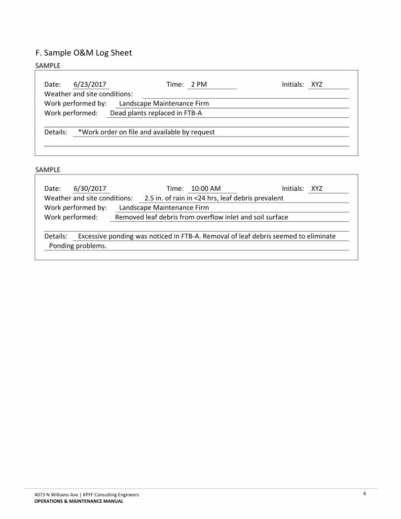
6
4073 N Williams Ave | KPFF Consulting Engineers
OPERATIONS & MAINTENANCE MANUAL
F. Sample O&M Log Sheet
SAMPLE
Date: 6/23/2017 Time: 2 PM Initials: XYZ
Weather and site conditions:
Work performed by: Landscape Maintenance Firm
Work performed: Dead plants replaced in FTB-A
Details: *Work order on file and available by request
SAMPLE
Date: 6/30/2017 Time: 10:00 AM Initials: XYZ
Weather and site conditions: 2.5 in. of rain in <24 hrs, leaf debris prevalent
Work performed by: Landscape Maintenance Firm
Work performed: Removed leaf debris from overflow inlet and soil surface
Details: Excessive ponding was noticed in FTB-A. Removal of leaf debris seemed to eliminate
Ponding problems.

7
4073 N Williams Ave | KPFF Consulting Engineers
OPERATIONS & MAINTENANCE MANUAL
G. O&M Log Sheet
Date: Time: Initials:
Weather and site conditions:
Work performed by:
Work performed:
Details:
Date: Time: Initials:
Weather and site conditions:
Work performed by:
Work performed:
Details:
Date: Time: Initials:
Weather and site conditions:
Work performed by:
Work performed:
Details:
Date: Time: Initials:
Weather and site conditions:
Work performed by:
Work performed:
Details:

8
4073 N Williams Ave | KPFF Consulting Engineers
OPERATIONS & MAINTENANCE MANUAL
H. Appendix: Exhibits
Exhibit A: Proposed Onsite System

PSU Peter Stott Center Renovation | KPFF Consulting Engineers
OPERATIONS & MAINTENANCE MANUAL
This page left blank for double-sided printing

RETAIL
RETAIL
PARKING
LOBBY
ELEVATORSTAIR 1
STAIR 2
WATERRISER ROOM
TRASH
N MASON STREET
N W
ILLI
AMS
AVEN
UE
ALLE
Y
EX1BEXA
PROPOSED ONSITE SYSTEM