Embed Size (px)
Citation preview
CareFreseniusMedical
4008 E / 4008 B / 4008 H / 4008 S
Hemodialysis system
Technical Manual
Edition: 5/03.09Part no.: M40 618 1
Software 4.5/5.3 and higher

Fresenius Medical Care 4008 5/03.09 (TM) 0-1
Important information on the Technical Manual
How to use the Technical Manual
Identification The document can be identified by the following information on the title page andon the labels, if any:– Edition of the technical document– Part number of the technical document
Page identification The page identification 1-3, for example, refers to: chapter 1, page 3.
Editorial information The editorial information 1/01.05, for example, refers to the 1st edition, January2005.
Changes Changes to the Technical Manual will be released as new editions or supple-ments. In general: This manual is subject to change without notice.
Significance of the Explanation of the Caution and Note symbols used:safety precautions
☞ NoteInforms the operator that if the steps are not followed as described, a specificfunction will be executed incorrectly or will not be executed at all, or will notproduce the desired effect.
CautionAdvises the operator against certain procedures or actions that could causedamage to the equipment or may have adverse effects on operators andpatients.
0-2 Fresenius Medical Care 4008 5/03.09 (TM)
Important information on the system
Technician’s qualification
Purpose This Technical Manual is intended for service technicians and is to be used forfirst studies (to acquire a basic knowledge) and for reference purposes (for TSC,Maintenance and repair). The Technical Manual, however, does not replace thetraining courses offered by the manufacturer.
Requirements Knowledge of the current Operating Instructions for the respective system.Background experience in mechanics, electrical and medical engineering.
Precautions for working on the system
Authorized persons Assembly, extensions, adjustments, modifications or repairs may only be carriedout by the manufacturer or persons authorized by him.
Test equipment and The activities described in this technical document require the availability of theaccessories necessary technical test equipment and accessories.
Specifications For the specifications of the respective system, refer to the current OperatingInstructions. Observe the information on the specifications.
Precautions Before turning power on, repair any visible damage.Prior to opening the system and when working on the open system, the followingprecautions have to be observed:– Protect the components against ingress of fluids.– Do not touch live parts (e.g. connectors of the power cable or heater).– Disconnect and connect all jacks, connectors and components only when the
system is turned off.
ESD precautions When repairing the system and replacing spare parts, observe the applicableESD precautions.
Hygienic measures The system and the consumables are generally considered to be contaminatedand must therefore be sufficiently disinfected by the responsible organization asspecified by the manufacturer.

Fresenius Medical Care 4008 5/03.09 (TM) 0-3
Addresses
Please address any inquiries to:
Manufacturer Fresenius Medical Care AG & Co. KGaAD-61346 Bad Homburg+49 (0)6172-609-0www.fmc-ag.com
Service Fresenius Medical CareCentral Europe Deutschland GmbH
Geschäftsbereich ZentraleuropaKundendienst / ServicecenterSteinmühlstraße 2461352 Bad HomburgGermanyPhone: +49 (0)6172-609-7100Fax: +49 (0)6172-609-7102E-mail: [email protected]
International Fresenius Medical Careservice Deutschland GmbH
Service Support InternationalHafenstraße 9D-97424 SchweinfurtGermanyPhone: +49 (0)9721-678-333 (hotline)Fax: +49 (0)9721-678-130
Local service

0-4 Fresenius Medical Care 4008 5/03.09 (TM)
Fresenius Medical Care 4008 5/03.09 (TM) 0-5
Table of contents
Section Page
1 Description of system functions and malfunctions ................................................. 1-1.1 Description of the T1 test ............................................................................................... 1-31.2 Functional description of the modules ............................................................................ 1-781.3 Functional description of the hydraulic unit .................................................................... 1-83
2 Technical Safety Checks / Maintenance .................................................................... 2-2.1 Technical Safety Checks and Maintenance
for 4008 hemodialysis systems and options .................................................................. 2-32.2 TSC report ...................................................................................................................... 2-25
3 Adjustment instructions .............................................................................................. 3-3.1 Overview of the DIP switches in the 4008...................................................................... 3-93.2 Calibration mode ............................................................................................................ 3-133.3 Hydraulics ....................................................................................................................... 3-153.4 Air detector ..................................................................................................................... 3-31
4 Calibration program ..................................................................................................... 4-
5 Diagnostics program .................................................................................................... 5-5.1 General notes ................................................................................................................. 5-35.2 Menu structure ................................................................................................................ 5-55.3 Reading the analog inputs of CPU I ............................................................................... 5-75.4 Reading the analog inputs of CPU II .............................................................................. 5-95.5 Reading the digital inputs of CPU I ................................................................................ 5-105.6 Reading the digital inputs of CPU II ............................................................................... 5-155.7 Writing the analog outputs of CPU I ............................................................................... 5-195.8 Writing the analog outputs of CPU II .............................................................................. 5-205.9 Writing the digital outputs of CPU I ................................................................................ 5-215.10 Writing the digital outputs of CPU II ............................................................................... 5-275.11 Writing/Reading the digital outputs of CPU I .................................................................. 5-305.12 ONLINEplus™ module ..................................................................................................... 5-315.13 HPU ................................................................................................................................ 5-32
6 Setup menu ................................................................................................................... 6-6.1 Overview Setup menu settings....................................................................................... 6-36.2 Overview ......................................................................................................................... 6-76.3 Main menu 4008 E/B ...................................................................................................... 6-96.4 Main menu 4008 H/S ...................................................................................................... 6-37
7 Miscellaneous ............................................................................................................... 7-
0-6 Fresenius Medical Care 4008 5/03.09 (TM)
Section Page
8 Circuit diagrams and circuit descriptions ................................................................. 8-8.1 Block diagram 4008 ........................................................................................................ 8-38.2 Block diagram of voltage supply .................................................................................... 8-48.3 Block diagram of screen 4008 H/S ................................................................................. 8-58.4 Connection layout diagram............................................................................................. 8-68.5 P.C.B. LP 450-2 Level detector control (LD) .................................................................. 8-98.6 P.C.B. LP 493 Blood leak detector ................................................................................. 8-118.7 P.C.B. LP 624 Control board (BP) .................................................................................. 8-128.8 P.C.B. LP 630 Motherboard ........................................................................................... 8-138.9 P.C.B. LP 631 CPU 1 ..................................................................................................... 8-148.10 P.C.B. LP 632 CPU 2 ..................................................................................................... 8-168.11 P.C.B. LP 633 Input board ............................................................................................. 8-188.12 P.C.B. LP 634 Output board ........................................................................................... 8-208.13 P.C.B. LP 635 Display board .......................................................................................... 8-228.14 P.C.B. LP 636 External connectors ................................................................................ 8-248.15 P.C.B. LP 950 Control board (HEP) ............................................................................... 8-258.16 P.C.B. LP 644-4 Display board (HEP)............................................................................ 8-268.17 P.C.B. LP 645 Position sensor membrane pump........................................................... 8-278.18 P.C.B. LP 649-2 Display board (4008 B/S) .................................................................... 8-288.19 P.C.B. LP 742 Interference filter ..................................................................................... 8-308.20 P.C.B. LP 748 Display board (BP) ................................................................................. 8-318.21 P.C.B. LP 763 Multi interface board (COMMCO III) ...................................................... 8-328.22 P.C.B. LP 922 Display board (4008 S) ........................................................................... 8-338.23 P.C.B. LP 923 Traffic light (4008 H/S) ........................................................................... 8-348.24 P.C.B. LP 924 Display board (4008 H) .......................................................................... 8-358.25 P.C.B. LP 941 Hydraulics processor .............................................................................. 8-368.26 Heater board (power supply unit 4008) .......................................................................... 8-378.27 Power board (power supply unit 4008) .......................................................................... 8-38
Fresenius Medical Care 4008 5/03.09 (TM) 1-1
Table of contents1 Description of system functions and malfunctions
Section Page
1.1 Description of the T1 test ............................................................................................ 1-31.1.1 T1 test flow diagram, serial program steps .................................................................... 1-31.1.2 T1 test flow diagram, parallel program steps ................................................................. 1-51.1.3 Description of the T1 test incl. error messages .............................................................. 1-71.1.4 Description of system errors during the cleaning programs .......................................... 1-531.1.5 Error messages after turning power on .......................................................................... 1-701.1.6 Error messages during dialysis ...................................................................................... 1-71
1.2 Functional description of the modules ...................................................................... 1-781.2.1 Blood pump (arterial) ...................................................................................................... 1-781.2.2 Blood pump (Single-Needle), optional ........................................................................... 1-791.2.3 Heparin pump ................................................................................................................. 1-801.2.4 Air detector ..................................................................................................................... 1-82
1.3 Functional description of the hydraulic unit ............................................................. 1-83Fig.: Flow diagram .......................................................................................................... 1-83
1.3.1 Description of the hydraulic unit ..................................................................................... 1-851.3.2 Theory of operation of the balancing chamber .............................................................. 1-871.3.3 Central delivery system option ....................................................................................... 1-911.3.4 Program sequences during the cleaning programs ....................................................... 1-92
Fig.: Flow chart of cleaning programs – overview .......................................................... 1-92

1-2 Fresenius Medical Care 4008 5/03.09 (TM)
Fresenius Medical Care 4008 5/03.09 (TM) 1-3
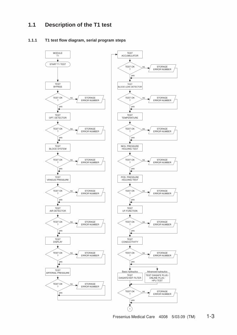
1.1 Description of the T1 test
1.1.1 T1 test flow diagram, serial program steps
1
START T1 TEST
MODULET1
TESTBYPASS
TEST OK?
no
yes
STORAGE ERROR NUMBER
TESTOPT. DETECTOR
TEST OK?
no
yes
STORAGEERROR NUMBER
TESTBLOOD SYSTEM
TEST OK?
no
yes
STORAGEERROR NUMBER
TESTVENOUS PRESSURE
TESTBLOOD LEAK DETECTOR
TEST OK?
no
yes
STORAGEERROR NUMBER
TESTTEMPERATURE
TEST OK?
no
yes
STORAGEERROR NUMBER
NEG. PRESSUREHOLDING TEST
TEST OK?
no
yes
STORAGEERROR NUMBER
POS. PRESSUREHOLDING TEST
TESTACCUMULATOR
TEST OK?
no
yes
STORAGEERROR NUMBER
TEST OK?
no
yes
STORAGEERROR NUMBER
TESTAIR DETECTOR
TEST OK?
no
yes
STORAGEERROR NUMBER
TESTDISPLAY
TEST OK?
no
yes
STORAGEERROR NUMBER
TESTARTERIAL PRESSURE
TEST OK?
no
yes
STORAGEERROR NUMBER
TEST OK?
no
yes
STORAGEERROR NUMBER
TESTUF-FUNCTION
TEST OK?
no
yes
STORAGEERROR NUMBER
TESTCONDUCTIVITY
TEST OK?
no
yes
STORAGEERROR NUMBER
TESTDIASAFE/HDF FILTER
TEST OK?
no
yes
STORAGEERROR NUMBER
TEST DIASAFE PLUS / ONLINE PLUS /
HPU TEST
Basic hydraulics Advanced hydraulics

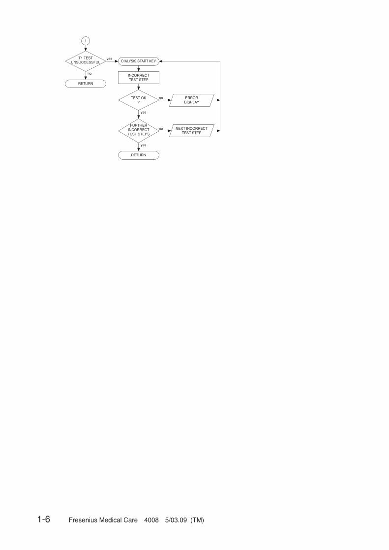
1-4 Fresenius Medical Care 4008 5/03.09 (TM)
1
T1 TESTUNSUCCESSFUL
yes
no
RETURN
DIALYSIS START KEY
TEST OK?
no
yes
ERRORDISPLAY
INCORRECTTEST STEP
FURTHERINCORRECTTEST STEPS
yes
no
NEXT INCORRECTTEST STEP
RETURN

Fresenius Medical Care 4008 5/03.09 (TM) 1-5
1.1.2 T1 test flow diagram, parallel program steps
1 1 1 1
1 1
1
1 1
TEST OK?
yes
no
POS. PRESSUREHOLDING TEST
STORAGEERROR NUMBER
TEST OK?
yes
no
TESTCONDUCTIVITY
TEST OK?
yes
no
TESTUF-FUNCTION
TESTDIASAFE/HDF FILTER
STORAGEERROR NUMBER
STORAGEERROR NUMBER
TESTCONDUCTIVITY
Conductivity?yesno
STORAGEERROR NUMBER
START T1 TEST
MODULET1
TEST OK?
yes
no
TESTOPT. DETECTOR
TEST OK?
yes
no
TESTBLOOD SYSTEM
TEST OK?
yes
no
TESTBYPASS
TEST OK?
yes
no
TESTDISPLAY
TEST OK?
yes
no
TESTACCUMULATOR
TEST OK?
yes
no
TESTARTERIAL PRESSURE
STORAGEERROR NUMBER
STORAGEERROR NUMBER
STORAGEERROR NUMBER
STORAGEERROR NUMBER
STORAGEERROR NUMBER
TEST OK?
yes
no
TESTVENOUS PRESSURE
TEST OK?
yes
no
TESTTEMPERATURE
STORAGEERROR NUMBER
STORAGEERROR NUMBER
STORAGEERROR NUMBER
TEST OK?
yes
no
TESTAIR DETECTOR
TEST OK?
yes
no
NEG. PRESSUREHOLDING TEST
TEST OK?
yes
no
TESTBLOOD LEAK DETECTOR
STORAGEERROR NUMBER
STORAGEERROR NUMBER
TEST OK?
yes
no
STORAGEERROR NUMBER
TEST OK?
yes
no
STORAGEERROR NUMBER
POS. PRESSUREHOLDING TEST
TEST OK?
yes
no
STORAGEERROR NUMBER
TEST OK?
no
TESTUF-FUNCTION
TEST OK?
no
TESTDIASAFE/HDF FILTER
STORAGEERROR NUMBER
STORAGEERROR NUMBER
yes yes
TESTDIASAFE/HDF FILTER
TEST DIASAFE PLUS / ONLINE PLUS /
HPU-TEST
Basic hydraulics Advanced hydraulics
1-6 Fresenius Medical Care 4008 5/03.09 (TM)
1
T1 TESTUNSUCCESSFUL
yes
no
RETURN
DIALYSIS START KEY
TEST OK?
no
yes
ERRORDISPLAY
INCORRECTTEST STEP
FURTHERINCORRECTTEST STEPS
no
yes
NEXT INCORRECTTEST STEP
RETURN
Fresenius Medical Care 4008 5/03.09 (TM) 1-7
1.1.3 Description of the T1 test incl. error messages
● Prerequisites for starting and running the test
Error message Description
Power failure Power failure while the test is in progress
Dialines not conn The dialysate lines are not in the interlock shunt.
Shunt Cover open The interlock shunt is open.
Connect Conc.LineWrong conc. supply The concentrate connector is in the rinse chamber, or concen-
trate is not connected at all. The error message depends on thecentral delivery system preselected in the setup menu.
Blood Sensed by OD The optical detector senses blood in the system.
Flow alarm Line to or from the dialyzer kinked, malfunctions in the hydraul-ics.
Water alarm Water supply interrupted.
XXX not calibrated A valid calibration value is missing in the NOVRAM.
● Overview of the individual test steps
Bypass test ..................................................................................................................... 1-8Optical detector test ....................................................................................................... 1-10Blood system test ........................................................................................................... 1-12Venous pressure system test ......................................................................................... 1-16Air detector test .............................................................................................................. 1-18Display test ..................................................................................................................... 1-22Arterial pressure system test .......................................................................................... 1-24Battery test ..................................................................................................................... 1-26Blood leak test ................................................................................................................ 1-28Temperature test ............................................................................................................ 1-30Negative pressure holding test ....................................................................................... 1-32Positive pressure holding test ........................................................................................ 1-34UF function test .............................................................................................................. 1-39Conductivity test ............................................................................................................. 1-42Diasafe/HDF filter test .................................................................................................... 1-44Online plus / Diasafe plus filter / HPU test ..................................................................... 1-48
1-8 Fresenius Medical Care 4008 5/03.09 (TM)
● Bypass test
Test description:
Check of the following functions:– Heater relay– Bypass (electric)– Check of the temperature range changeover
Illustration:
LP 632
CPU 2
LP 633
Inputboard
LP 631
board
LP 630
MotherCPU 1 DATA BUS
LP 634
Power
H_REL_W
EM_H_OFF
V24_EN
V24B_EN
CI
V26
V24B
V24
Rueckmeldung/Acknowledgement
Testgenerierung/Generation of Test
V24 V24B V26
X631/A20 X631/A21
X632/B27 X632/B28
X632/A4
X632/A5
X632/A6
X632/B22
X632/C26
X632/C25
X632/A6
X632/A9
X632/A10 X639/A12
X639/A17
C22A18
X634R/ X634R/
V26
X634R/ X634R/
A23
V24
V24B
V26
X6
34
L/C
25
X6
34
L/C
12
X634L
/A25
HOT_RINSE
C24
X639/
A20
X632/A26
Logic
LP 639(4008E/H)
LP 647(4008S/B)
Outputboard
LP 635(4008 E)
LP 649(4008 B)
LP 922(4008 S)
LP 924(4008 H)
Displayboard

Fresenius Medical Care 4008 5/03.09 (TM) 1-9
Error description:
Error message Description
F 01 Bypass The heater relay is switched off.– Acknowledgement (H_REL_W, X639/A12) → X632/A10, 0 V are
missing.
F 02 Bypass The heater relay cannot be switched off by CPU2.– Acknowledgement (H_REL_W, X639/Y12) → X632/A10, 12 V are
missing.– Control line (EM_H_OFF, X632/A9) → X639/A17, 12 V are missing.
F 03 Bypass The temperature measurement range is set to hot rinse.– Control line (HOTRINSE, X634R/C24) → X639/A20, 0 V are miss-
ing.– Acknowledgement (HOTRINSE, X634R/C24) → X632/A26, 0 V are
missing.
F 04 Bypass The extended bypass cannot be correctly switched by CPU2 (V24 = off,V26 = on, V24B = off).– Acknowledgement (V24, X637/C1) → X632/A4, 24 V are missing.– Acknowledgement (V26, X637/C2) → X632/A6, 0 V are missing.– Acknowledgement (V24B, X637/C23) → X632/A5, 24 V are miss-
ing.
F 05 Bypass The extended bypass cannot be correctly switched off by CPU2 (V24 =on, V26 = off, V24B = on).– Acknowledgement (V24, X637/C1) → X632/A4, 0 V are missing.– Acknowledgement (V26, X637/C2) → X632/A6, 24 V are missing.– Acknowledgement (V24B, X637/C23) → X632/A5, 0 V are missing.
F06 Bypass CPU1 fails to set the temperature control to hot rinse.– Control line (HOTRINSE, X634R/C24) → X639/A20, 12 V are miss-
ing.– Acknowledgement (HOTRINSE, X634R/C24) → X632/A26, 12 V
are missing.
F 07 Bypass The extended bypass cannot be correctly switched by CPU1 (V24 = off,V26 = on, V24B = off).– Acknowledgement (V24, X637/C1) → X632/A4, 24 V are missing.– Acknowledgement (V26, X637/C2) → X632/A6, 0 V are missing.– Acknowledgement (V24B, X637/C23) → X632/A5, 24 V are miss-
ing.
F08 Bypass CPU1 fails to reset the temperature control to dialysis.– Control line (HOTRINSE, X634R/C24) → X639/A20, 0 V are miss-
ing.– Acknowledgement (HOTRINSE, X634R/C24) → X632/A26, 0 V are
missing.
F09 Bypass The extended bypass cannot be correctly switched off by CPU1 (V24 =on, V26 = off, V24B = on).– Acknowledgement (V24, X637/C1) → X632/A4, 0 V are missing.– Acknowledgement (V26, X637/C2) → X632/A6, 24 V are missing.– Acknowledgement (V24B, X637/C23) → X632/A5, 0 V are missing.
F95 Bypass System error
1-10 Fresenius Medical Care 4008 5/03.09 (TM)
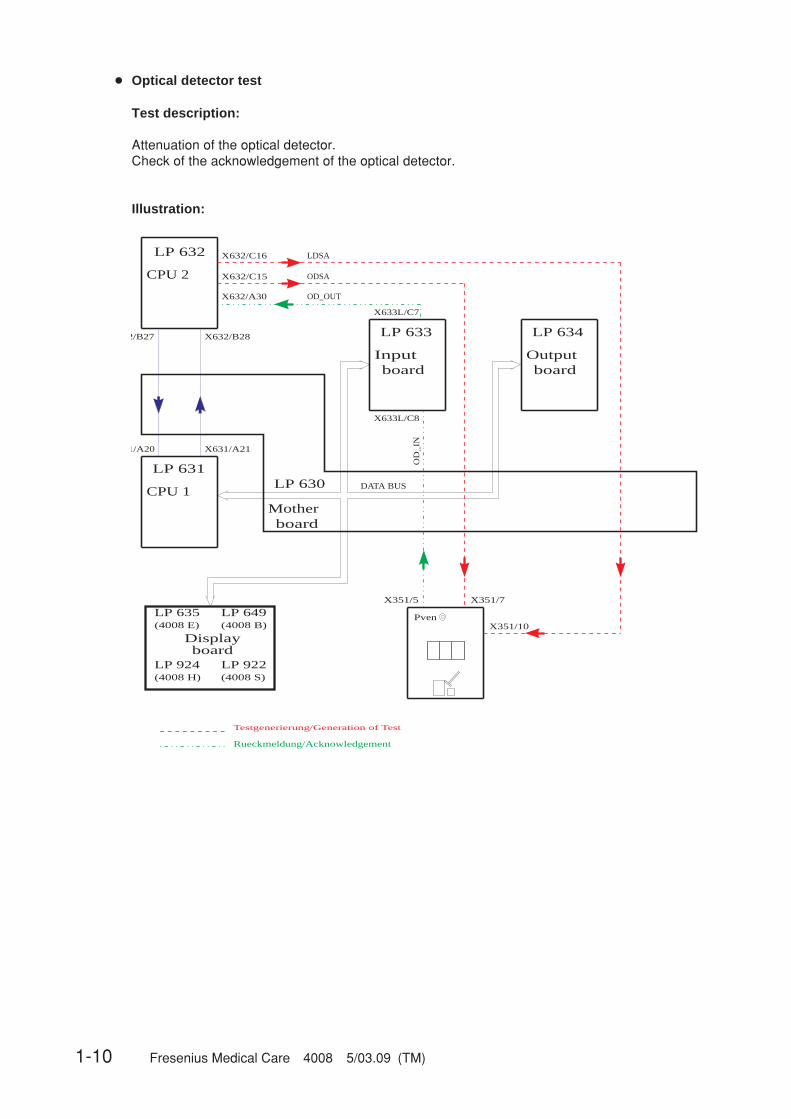
● Optical detector test
Test description:
Attenuation of the optical detector.Check of the acknowledgement of the optical detector.
Illustration:
LP 632
CPU 2
LP 633
Inputboard board
LP 634
Output
LP 631
board
LP 630
MotherCPU 1 DATA BUS
ODSA
OD_OUT
OD
_IN
Rueckmeldung/Acknowledgement
Testgenerierung/Generation of Test
32/B27 X632/B28
31/A20 X631/A21
X632/C15
X632/A30
X633L/C7
X633L/C8
X351/5 X351/7
Pven
X632/C16 LDSA
X351/10
LP 635(4008 E)
LP 649(4008 B)
LP 922(4008 S)
LP 924(4008 H)
Displayboard
Fresenius Medical Care 4008 5/03.09 (TM) 1-11
Error description:
Error message Description
F01 opt. Detector CPU1 interprets the optical detector in a different way than does CPU2.– Acknowledgement (OD_OUT, X633L/C7) → X632/A30 and the
digital input of P.C.B. LP 633 measure different levels.
F02 opt. Detector CPU2 fails to recognize blood in the system.– Acknowledgement (OD_OUT, X633L/C7) → X632/A30, 0 V are
missing.– Detuning (ODSA, X632/C15) → X351/7 not 12V.
F03 opt. Detector CPU1 fails to recognize blood in the system.– Acknowledgement (OD_OUT, X633L/C7) → digital input on P.C.B.
LP 633.– Detuning (ODSA, X632/C15) → X351/7 not 12V.
F04 opt. Detector CPU2 recognizes that the optical detector senses opaque fluid (re-quired because of the test in the cleaning program).– Acknowledgement X632/A30 not 12V.– AD28 defective.
F96 opt. Detector System error.

1-12 Fresenius Medical Care 4008 5/03.09 (TM)
● Blood system test
Test description:
Check of the following functions:– Blood alarm acknowledgement– Blood pump switch-off
Illustration:
LP 632
CPU 2
LP 633
Input
board
LP 634
(4008E/H)
LP 647
(4008S/B)
Output
board
LP 631
board
LP 630
Mother
LP 635
(4008 E)
LP 649
(4008 B)
LP 922
(4008 S)
LP 924
(4008 H)
Display
board
CPU 1DATA BUS
LDA2
BL_AL
BPSB_ART
SN_ART
Pven
Rückmeldung/Acknowledgement
Testgenerierung/Generation of Test
X632/B27 X632/B28
X631/A20 X631/A21
X632/C14
X632/C21
X632/A11
X632/A15
C15
X634L/
CLP_CTLX632/C10
X633L/
C13
A13 X633L/
X351/8
A14
X351/6
BP
ST
_A
RT
BPSST_A
C14
X634L/
B14
X634L/
X634L/
X3
48
a/2
X348a/6
X3
48
a/3
X3
48
a/1
X348/V
6
X3
48
/V
3
X3
48
/V
1
BPSB_VEN
A15
B15
BP
SS
T_V
X632/B11
Fresenius Medical Care 4008 5/03.09 (TM) 1-13
Error description:
Error message Description
F09 Bloodsystem Acknowledgement that CPU2 recognizes that the arterial blood pumpis inactive (BP not running).– Acknowledgement (BPSB_ART, X348a/6) → X632/A11, 12 V miss-
ing.– Control line (BPSST_ART, X634L/B14) → X348a/1, 12 V missing or
(BPST_ART, X634L/A14) → X348a/3, 12 V are missing.
F10 Bloodsystem Acknowledgement that CPU1 recognizes that the arterial blood pumpis inactive (BP not running).– Acknowledgement (BPSB_ART, X348a/6) → X633L/A11, 12 V are
missing.– Control line (BPSTT_ART, X634L/B14) → X348a/1, 12 V missing or
(BPST_ART, X634L/A14) → X348a/3, 12 V missing.– Level is raised during the T1 test.
F11 Bloodsystem The arterial blood pump cannot be stopped by CPU1.CPU2 recognizes that the arterial blood pump remains active.– Control line (BPSST_ART, X634L/B14) → X348a/1, 0 V missing,
as well as (BPST_ART, X634L/A14) → X348a/3, 0 V missing.– Acknowledgement (BPSB_ART, X348a/6) → X632/A11, 0 V are
missing.– The level is raised during the T1 test, or the up/down key on the air
detector is blocked and the level is constantly raised.
F12 Bloodsystem The arterial blood pump cannot be stopped by CPU1.CPU1 recognizes that the arterial blood pump remains active.– Control line (BPSST_A, X634L/B14) → X348a/1, 0 V missing,
as well as (BPST_ART, X634L/A14) → X348a/3, 0 V missing.– Acknowledgement (BPSB_ART, X348a/6) → X633L/A11, 0 V are
missing.
F13 Bloodsystem Applicable for SW 4.91/2.91 and higher if SN, ONLINE-HDF or4008 HDF pump is connected (= ADKS active)Acknowledgement that CPU2 detects that the pump is inactive (pumpis not running).– Acknowledgement (BPSB_VEN, X348V/6) → X632/ B11, 12V
missing– Control line (BPSST_VEN, X634L/B15) → X348V/1, 12V missing or
(BPST_VEN, X634L/A15) → X348V/3, 12V missing– Transistor T9 on P.C.B. LP 754 defective– IC5 on P.C.B. LP 632 defective– In 4008 HDF an HDF treatment was performed, followed by a
cleaning program with the substituate pump running, then the T1test has been re-started.The substituate pump must be switched off because otherwise thetest step will fail to be passed (problem was corrected with SW 3.20in 4008 H/S systems: the substituate pump will be switched offautomatically on starting a cleaning program).

1-14 Fresenius Medical Care 4008 5/03.09 (TM)
F14 Bloodsystem Applicable for SW 4.91/2.91 and higher if SN, ONLINE-HDF or4008 HDF pump is connected (= ADKS active)Acknowledgement that CPU1 detects that the pump is inactive (pumpis not running).– Acknowledgement (BPSB_VEN,X348V/6) → X633L/A13, 12V
missing– Control line (BPSST_VEN, X634L/B15) → X348V/1 not 12V or
(BPST_VEN, X634L/A15) → X348V/3 not 12V– IC16 on P.C.B. LP 633 defective– P.C.B. LP 633 recognizes Single-Needle pump although it is not
connected.
F15 Bloodsystem Applicable for SW 4.91/2.91 and higher if SN, ONLINE-HDF or4008 HDF pump is connected (= ADKS active)CPU1 fails to stop the corresponding blood pump.CPU2 detects that the pump remains active.– Control line (BPSST_VEN, X634L/B15) → X348V/1, 0V missing as
well as (BPST_VEN, X634L/A15) → X348V/3 not 0V– Acknowledgement (BPSB_VEN, X348V/6) → X632/B11, 0V miss-
ing– Transistor T9 on P.C.B. LP 754 defective– IC5 on P.C.B. LP 632 defective– During the test the lines are inserted on the corresponding pump
using the Start/Stop key.– P.C.B. LP 633 recognizes Single-Needle pump although it is not
connected.
F16 Bloodsystem Applicable for SW 4.91/2.91 and higher if SN, ONLINE-HDF or4008 HDF pump is connected (= ADKS active)CPU1 fails to stop the corresponding blood pump.CPU1 detects that the pump remains active.– Control line (BPSST_VEN, X634L/B15) → X348V/1 not 0V as well
as (BPST_VEN, X634L/A15) → X348V/3 not 0V– Acknowledgement (BPSB_VEN, X348V/6) → X633L/A13 not 0V– IC16 on P.C.B. LP 633 defective– P.C.B. LP 633 recognizes Single-Needle pump although it is not
connected.
F17 Bloodsystem Applicable for SW 4.91/2.91 and higher if SN, ONLINE-HDF or4008 HDF pump is connected (= ADKS active)Although the recognition of the venous blood pump (ADKS) is notacknowledged, the 24-V supply voltage of the pump can be switchedoff.– Acknowledgement line (ADKS, X348V/7) → X633L/A10 not 12V– Acknowledgement (BPSB_VEN, X348V/6) → X633L/A13 not 12V– Acknowledgement (BPSB_VEN, X348V/6) → X632/B11 not 12V– Online-HDF has already been switched on during the T1 test.– IC16 on P.C.B. LP 633 defective.

Fresenius Medical Care 4008 5/03.09 (TM) 1-15
F18 Bloodsystem Applicable for SW 5.00/4.10 and higher, check of the BPUS signal(CPU, P.C.B. LP 632)At the beginning of the test step a maximum of 40s may pass untilrotation has stopped.If the blood pump is being activated, the rotationstop alarm must have been cleared.– Acknowledgement line (BPUS, X348A/8) → X632/A13 not 0V– Acknowledgement line (BPUS, X348A/8) → X632/A13 not 12V– Blood pump speed is set to “0”: preset speed during the T1 test.
F19 Bloodsystem Applicable for SW 5.00/4.10 and higher, check of the BPUS signal(CPU, P.C.B. LP 631 via LP 633)At the beginning of the test step a maximum of 40s may pass untilrotation has stopped. If the blood pump is being activated, the rotationstop alarm must have been cleared.1. Acknowledgement line (BPUS, X348A/8) → X633L/A12 not 0V2. Acknowledgement line (BPUS, X348A/8) → X633L/A12 not 12V
F20 Bloodsystem Check of the actual arterial BP rate.The actual rate of the arterial BP is not zero. The actual rate of thearterial BP does not increase.If SN is installed: The actual rate of the venous BP is not zero. Theactual rate of the venous BP does not increase.– Acknowledgement line (BPR_ART, X348A/10) → X633L/B3 not 0V
or acknowledgement line (BPR_ART, X348A/10) → X632/A14 not0V
– Acknowledgement line (BPR_ART, X348A/10) → X633L/B3 noincrease or acknowledgement line (BPR_ART, X348A/10) → X632/A14 no increase
If SN is installed:– Acknowledgement line (BPR_VHDF, X348V/10) → X633L/B4 not
0V– Acknowledgement line (BPR_VHDF, X348V/10) → X633L/B4 no
increase
F95 Bloodsystem System error.
1-16 Fresenius Medical Care 4008 5/03.09 (TM)
● Venous pressure system test
Test description:
Verification of the lower limit by checking the venous zero point.The upper limit is tested by detuning the venous pressure unit in positive direction.(The venous line clamp is closed during the test.)
Illustration:
PV_DET
PVEN
DATA BUS
Mother
LP 630
board
Output
LP 634
boardboardInput
LP 633
VE
NT
_V
X632/B27 X632/B28
X631/A20 X631/A21
X351/2
X351/4
X351/1
X632/C17
X632/C18
X633L/B5 X634R/C18
CPU 2
LP 632
CPU 1
LP 631
Rueckmeldung/Acknowledgement
Testgenerierung/Generation of Test
X632/C16 LDSA
X351/10
P_VEN
LP 635(4008 E)
LP 649(4008 B)
LP 922(4008 S)
LP 924(4008 H)
Displayboard

Fresenius Medical Care 4008 5/03.09 (TM) 1-17
Error description
Error message Description
F01 Venous CPU1 (input board) shows a venous zero point deviation of more than±12 mmHg (60 s).– Control (VENT_VALVE, X634R/C18) → X351/1 of the vent valve in
the LD is defective.– Acknowledgement (P_VEN, X351/4) → X633L/B5 that the voltage
value is outside the zero point tolerance.– P-venous has not been calibrated.
F02 Venous CPU2 shows a venous zero point deviation of more than ±12 mmHg(60 s).– Control (VENT_VALVE, X634R/C18) → X351/1 of the vent valve in
the LD is defective.– Acknowledgement (P_VEN, X351/4) → X632/C17, the voltage
value is outside the zero point tolerance.– P-venous has not been calibrated.
F03 Venous With detuning in positive direction, the achieved change in the venousdisplay is less than 100 mmHg (7 s).– The test detuning is defective (PV_DET, X632/C18) → X351/2.– Acknowledgement (P_VEN, X351/4) → X633L/B5, the change in
voltage is too low.– P-venous has not been calibrated.
F04 Venous The deviation in the measured value between CPU1 and CPU2 ishigher than ±12 mmHg (if Pven > 100 mmHg).– Acknowledgement (P_VEN, X351/4) → X633L/B5 and X632/C17
measure different voltage values.– P-venous has not been calibrated.
F95 Venous System error.

1-18 Fresenius Medical Care 4008 5/03.09 (TM)
● Air detector test
Test description:
– Test of the air detector by checking the alarm state.– Switch-off of the venous line clamp in the air detector module.
Illustration:
Fresenius Medical Care 4008 5/03.09 (TM) 1-19
Error description:
Error message Description
F01 Airdetector CPU1 interprets the air detector signal in a different way than doesCPU2.– Acknowledgements (LDA1, X351/14) → X632/C13 and X633L/C10
recognize different signal levels.
F02 Airdetector The air detector alarm is not recognized by CPU2.– Acknowledgement (LDA1, X351/14) → X632/C13, 0 V are missing.– Transmission weakening (LDSA, X632/C16) → X351/10, 12 V are
missing.
F03 Airdetector Air detector clamps acknowledgement (CPU2) activated (clampclosed).– Acknowledgement (LDA2, X351/6) → X632/C14, 24 V are missing.– Clamp control (CLP_CTL, X634L/C14) → X351/8, 12 V are missing.– Clamp control (CLP_CTL, X632/C10) → X351/8, 12 V are missing.
F04 Airdetector Air detector clamps acknowledgement (CPU1) activated (clampclosed).– Acknowledgement (LDA2, X351/6) → X633L/C13, 24 V are miss-
ing.– Clamp control (CLP_CTL, X634L/C14) → X351/8, 12 V are missing.– Clamp control (CLP_CTL, X632/C10) → X351/8, 12 V are missing.
F05 Airdetector The blood alarm signal has not been cleared (indicates an alarm).– Acknowledgement (BL_AL, X634L/C15) → X632/C21, 12 V are
missing.If the HDF option is used, this signal is not tested (special function).
F06 Airdetector Closing of the air detector clamp via the CPU2 control line was notpossible.– Clamp control (CLP_CTL, X632/C10) → X351/8, 0 V are missing.– Acknowledgement (LDA2, X351/6) → X632/C14, 0 V are missing.
F07 Airdetector Opening of the air detector clamp via the CPU2 control line was notpossible.– Clamp control (CLP_CTL, X632/C10) → X351/8, 12 V are missing.– Acknowledgement (LDA2, X351/6) → X632/C14, 24 V are missing.
F08 Airdetector Closing of the air detector clamp via the CPU1 control line was notpossible, or CPU2 acknowledgement is incorrect.– Clamp control (CLP_CTL, X634L/C14) → X351/8, 0 V are missing.– Acknowledgement (LDA2, X351/6) → X632/C14, 0 V are missing.
1-20 Fresenius Medical Care 4008 5/03.09 (TM)
F09 Airdetector Closing of the air detector clamp via the CPU1 control line was notpossible, or CPU1 acknowledgement is incorrect.– Clamp control (CLP_CTL, X634L/C14) → X351/8, 0 V are missing.– Acknowledgement (LDA2, X351/6) → X633L/C13, 0 V are missing.
F10 Airdetector The blood alarm message is missing.– Acknowledgement (BL_AL, X634R/C15) → X632/C21, 0 V are
missing.If the HDF option is used, this signal is not tested (special function).
F11 Airdetector Air detector clamps acknowledgement (CPU2) activated (clampclosed).– Acknowledgement (LDA2, X351/6) → X632/C14, 24 V are missing.– Clamp control (CLP_CTL, X634L/C14) → X351/8, 12 V are missing.– Clamp control (CLP_CTL, X632/C10) → X351/8, 12 V are missing.
F12 Airdetector Air detector clamps acknowledgement (CPU1) activated (clampclosed).– Acknowledgement (LDA2, X351/6) → X633L/C13, 24 V are miss-
ing.– Clamp control (CLP_CTL, X634L/C14) → X351/8, 12 V are missing.– Clamp control (CLP_CTL, X632/C10) → X351/8, 12 V are missing.
F13 Airdetector The blood alarm signal has not been cleared (indicates alarm).– Acknowledgement (BL_AL, X634L/C15) → X632/C21, 12 V are
missing.If the HDF option is used, this signal is not tested (special function).
F14 Airdetector Raise level key on the air detector is constantly active.– Acknowledgement (LEVEL_UP, X351/3) → X632/C11 not 0V.
F15 Airdetector Acknowledgement of the supply voltage for the ultrasonic output stagenot between 6.5 and 13.5 V after 3 seconds.– Adapter board AD28 not connected– Acknowledgement (X351/11 → X633L/25A jumper to X633L/B7)
not 12V.– Relay on AD28 failed to drop.
F16 Airdetector Acknowledgement of the supply voltage for the ultrasound output stagenot >14.5V after 3 seconds.– Adapter board AD28 not connected.– Acknowledgement (X351/11 → X633L/25A jumper to X633L/B7)
not 16V/24V.– Relay on AD28 is not controlled.– No 10-Hz signal at ALARM_REST (X351/12)
Fresenius Medical Care 4008 5/03.09 (TM) 1-21
F17 Airdetector Acknowledgement of the supply voltage for the ultrasound output stagenot between 6.5 and 13.5 V after 3 seconds.– Adapter board AD28 not connected– Acknowledgement (X351/11 → X633L/25A jumper to X633L/B7)
not 12V– Relay on AD28 failed to drop
F95 Airdetector System error.

1-22 Fresenius Medical Care 4008 5/03.09 (TM)
● Display test
Test description:
Check of all displays and indicators on the monitor front– Display test– Status LED– Alarm LED– Seven-segment display, all dark– Seven-segment display, all 8888– Bar graph– CPU1/CPU2 alarm tone
This display test must be monitored by the user!
Illustration:
Rueckmeldung/Acknowledgement
Testgenerierung/Generation of Test
LP 632
CPU 2
LP 633
Inputboard board
LP 634
Output
LP 631
board
LP 630
MotherCPU 1 DATA BUS
X632/C29
X634R/A16
+LS X634L/A13
CPU2_AL
-LS X634L/B13
8888
8888
8888
8888
Test Display
X632/ B27 X632/ B28
X631/ A20 X631/ A21
LP 635(4008 E)
LP 649(4008 B)
LP 922(4008 S)
LP 924(4008 H)
Displayboard

Fresenius Medical Care 4008 5/03.09 (TM) 1-23
Error description:
Error message Description
F01 Display CPU1 failed to start the display test within 5 sec.– The “test started” information transmitted via the serial interface is
missing.
F02 Display CPU1 failed to complete the display test within 120 sec.– The “test completed” information transmitted via the serial interface
is missing.
F95 Display System error.

1-24 Fresenius Medical Care 4008 5/03.09 (TM)
● Arterial pressure system test
Test description:
Test of the arterial pressure unit by electronic detuning in positive or negative direction.
Illustration:
Fresenius Medical Care 4008 5/03.09 (TM) 1-25
Error description:
Error message Description
F01 Arterial With detuning in negative direction, the change achieved on the arterialdisplay is less than 100 mmHg (2 sec).– Acknowledgement (P_ART, X348A/7) → X633L/B12, insufficient
voltage change.– Test detuning defective (PA_DET, X632/A17) → X348A/9.
F02 Arterial With detuning in positive direction, the change achieved on the arterialdisplay is less than 100 mmHg (2 sec).– Acknowledgement (P_ART, X348A/7) → X633L/B12, insufficient
voltage change.– Test detuning defective (PA_DET, X632/A17) → X348A/9.
F95 Arterial System error.

1-26 Fresenius Medical Care 4008 5/03.09 (TM)
● Battery test
Test description:
Check of the battery voltage under load.
Illustration:
LP 632
CPU 2
LP 633
Inputboard board
LP 634
Output
LP 631
board
LP 630
MotherCPU 1 DATA BUS
Akku
Rueckmeldung/Acknowledgement
Testgenerierung/Generation of Test
X632/B27 X632/B28
X631/A20 X631/A21
X634R/C23
TESTBATT
X639/A10
X639/A2X639/A3
X633L/B21
U_ACCU
X639/A4
(16 - 22V)
PowerLogic
LP 639(4008E/H)
LP 647(4008S/B)
LP 635(4008 E)
LP 649(4008 B)
LP 922(4008 S)
LP 924(4008 H)
Displayboard
Fresenius Medical Care 4008 5/03.09 (TM) 1-27
Error description:
Error message Description
F01 Accumulator CPU1 failed to complete the battery test within 5 sec.– The “test completed” information transmitted via the serial interface
is missing.
F02 Accumulator The battery charge is insufficient for 15 min emergency operation(maybe no battery connected).– The battery voltage (U_ACCU, ...) → X633L/B21 dropped below
17.6 V.– Acknowledgement (U_ACCU, ...) → X633L/B21 of the battery volt-
age defective.
F03 Accumulator The test circuit on P.C.B. LP 639 defective.– The test level is incorrect (TESTBATT, X634R/C23) → X639/A10,
the 12-V pulse is missing (100 ms).– Power supply unit LP 639 SI5 or in 4008B/S systems fuse in the
base defective.– R39 on P.C.B. LP 639 (4008E/H) or P.C.B. LP 647 (4008B/S) de-
fective, possibly caused by flickering power supply unit.
F95 Accumulator System error.

1-28 Fresenius Medical Care 4008 5/03.09 (TM)
● Blood leak test
Test description:
Test of the blood leak detector by lowering the capacity of the transmitting diode.
Illustration:
Fresenius Medical Care 4008 5/03.09 (TM) 1-29
Error description:
Error message Description
F01 Bloodleak Blood leak channel and dimness not in alarm-free condition during theT1 test.– Dimness channel contaminated (calcium precipitate, etc.)– Acknowledgement (BLL, X637A/18) → X633L/B10 voltage value
within the alarm tolerances (< 3V).– Acknowledgement (BLL_DIM, X637A/21) → X633L/B11 voltage
value within the alarm tolerances (<1.5V/ >8V).– DAC_BLL or DAC_DIM not within the tolerances (check calibration)
F02 Bloodleak The blood leak alarm/dimness alarm is not recognized during testdetuning.– Acknowledgement (BLL, X637A/18) → X633L/B10 voltage value
not within the alarm tolerances.– Acknowledgement (BLL_DIM, X637A/21 → X633L/B11 voltage val-
ue not within the alarm tolerances (<1.5V)– Test detuning (BLL_DET, X632/A25) → X633L/B27 not 5V– Calibration of DAC_BLL or DAC_DIM is too high– Detuning (DAC_DIM, X634R/A11) → X633L/C3 impossible– Dimness calibration is set to potentiometer calibration (BR6 from
pos. 1/2 to 2/3).
F03 Bloodleak After test detuning, the blood leak channel and dimness fail to enter thealarm-free state.– Dimness channel contaminated (calcium precipitate, etc.)– Acknowledgement (BLL, X637A/18) → X633L/B10 voltage value
within the alarm tolerances– Test detuning (BLL_DET, X632/A25) → X633L/B27 not 0V.– Acknowledgement (BLL_DIM, X637A/21) → X633L/B11 voltage
value within the alarm tolerances (<1.5V / >8V).– DAC_BLL or DAC_DIM not within the tolerances (check calibration)
F95 Bloodleak System error.

1-30 Fresenius Medical Care 4008 5/03.09 (TM)
● Temperature test
Test description:
Test of the upper alarm limit by electronically detuning the temperature display in positivedirection.
Illustration:
MO
N_N
TC
NT
C_B
IB
Rueckmeldung/Acknowledgement
Testgenerierung/Generation of Test
LP 632
CPU 2
LP 633
Input
board board
LP 634
Output
LP 631
board
LP 630
Mother
CPU 1DATA BUS
T_DETADJ
BIBAG_TE
T_DIAL1
HOTRINSE
X632/B27 X632/B28
X631/A20 X631/A21
X632/A26
X632/A24
X632/A23
X634R/C24
X6
33
R/C
25
X6
33
R/C
15
X633R/C21 X633L/B16
X634R/
A13
X633R/
A20
X639/A20
LP 635
(4008 E)
LP 649
(4008 B)
LP 922
(4008 S)
LP 924
(4008 H)
Display
board
Logic
LP 639
(4008E/H)
LP 647
(4008S/B)
Power
Logic
LP 639
(4008E/H)
LP 647
(4008S/B)
Fresenius Medical Care 4008 5/03.09 (TM) 1-31
Error description:
Error message Description
F01 Temperature The temperature measuring range is not set to hemodialysis.– Control line (HOTRINSE, X634R/C24) → X639/A20, 0 V are miss-
ing.– Acknowledgement (HOTRINSE, X634R/C24) → X632/A26, 0 V are
missing.
F02 Temperature The actual temperature is less than 35.0 °C (test running time > 15minutes).– Calibrate the temperature.– The heater rod failed.– Acknowledgement (T_DIAL1, X633L/B16) → X632/A24, voltage got
stuck.
F03 Temperature The actual temperature is higher than 39.0 °C (test running time > 15minutes).– Calibrate the temperature.– The regulating sensor (NTC-2) is defective.– Acknowledgement (T_DIAL1, X633L/B16) → X632/A24, voltage got
stuck.
F04 Temperature The temperature failed to stabilize within 15 minutes.– Acknowledgement (T_DIAL1, X633L/B16) → X632/A24 is steadily
changing (change > 0.3 °C/15 sec).
F05 Temperature Detuning in positive direction not higher than 3 °C (10 sec).– Acknowledgement (T_DIAL1, X633L/B16) → X632/A24, change in
voltage insufficient.– Detuning (T_DETADJ, X632/A23) → X633R/C21 insufficient.
F06 Temperature The monitor sensor indicates a constant value.– NTC-3 defective.
F07 Temperature The test release is missing (max. test running time is 10 minutes).– Run-time problem (software).
F08 Temperature CPU1 failed to transmit a Bibag status message within 3 sec.– Run-time problem (software).
F09 Temperature Bibag NTC_BIB detuning not higher than 1 °C.– Acknowledgement (NTC_BIB, X633R/C15) → ADW on P.C.B.
LP 633, change in voltage insufficient.– Detuning (BIBAG_TE, X634R/A13) → X633R/A20 insufficient.
F10 Temperature Bibag temperature display outside of measuring range (15 to 45 °C).– Acknowledgement (NTC_BIB, X633R/C15) → ADW on P.C.B.
LP 633.
F95 Temperature System error.

1-32 Fresenius Medical Care 4008 5/03.09 (TM)
● Negative pressure holding test
Test description:
Within a specific time period, the actual value of the dialysate pressure transducer should changewithin certain limits only.
Illustration:
UF_P_CTL
P_DIAL
UF
_P
_C
TL
+P
_D
IA
L
Rueckmeldung/Acknowledgement
Testgenerierung/Generation of Test
DATA BUS
Mother
LP 630
board
Output
LP 634
boardboard
Input
LP 633
X632/B28
X631/A20 X631/A21
X632/B27
X632/C27
X632/A29
X633L/B6
X633R/C28
X634R/A24
CPU 2
LP 632
CPU 1
LP 631
X634R/A24
CIX632/B22
X634R/A23
X632/A19
X634L/B10
ACKN_ASP
LP 635
(4008 E)
LP 649
(4008 B)
LP 922
(4008 S)
LP 924
(4008 H)
Display
board

Fresenius Medical Care 4008 5/03.09 (TM) 1-33
Error description:
Error message Description
F01 neg. Pressure During the start phase a negative pressure of more than 450 mmHghas developed (max. test running time 120 sec),– the hydraulic system is contaminated,– the air separation pump started running.
F02 neg. Pressure Setting the dialysate pressure to the test pressure (–300 mmHg to–450 mmHg) was not possible (max. test running time 120 sec).Upon repetition of measurement, the range was extended from–260 mmHg to 490 mmHg.– Leakage in the hydraulic system.– The UF pump is defective.– If the HDF filter test was skipped: Clamp the HDF filter.
F03 neg. Pressure The working point (116 digits) of the differential amplifier cannot be setcorrectly (max. test running time 120 sec).– Pressure variations are too large.– The D-A converter (IC11) on P.C.B. LP 632 is defective.– The operational amplifier (IC1/IC3) on P.C.B. LP 632 is defective.– The acknowledgement (P_DIAL, X633L/B6) → X632/A29 is defec-
tive.– The CI signal is missing (LP 632 → X632/B22).
F04 neg. Pressure Completion of pressure measurement was not possible (max. testrunning time 120 sec).– The D-A converter (IC11) on P.C.B. LP 632 is defective.– The operational amplifier (IC1/IC3) on P.C.B. LP 632 is defective.– The acknowledgement (P_DIAL, X633L/B6) → X632/A29 is defet-
ive.
F05 neg. Pressure The air separation pump started running during the measurementphase.– Acknowledgement (ACKN_ASP, X634L/B10) → X632/A19, 0 V are
missing.– ASP has been interrupted electrically.
F06 neg. Pressure The negative pressure holding test failed to be passed. The dialysatepressure drop exceeds ±40 mmHg (related to ten balancing chamberswitching).– Leakage in the hydraulic system.
F07 neg. Pressure Current increasing pulses were not recognized (min. 2x).– 5-V balancing chamber pulses are missing (CI. X634R/A23) →
X632/B22.
F95 neg. Pressure System error.
In systems with HDF option, the negative pressure holding test is performed internally only; i.e.V24, V24B are closed and V26 is open.
1-34 Fresenius Medical Care 4008 5/03.09 (TM)
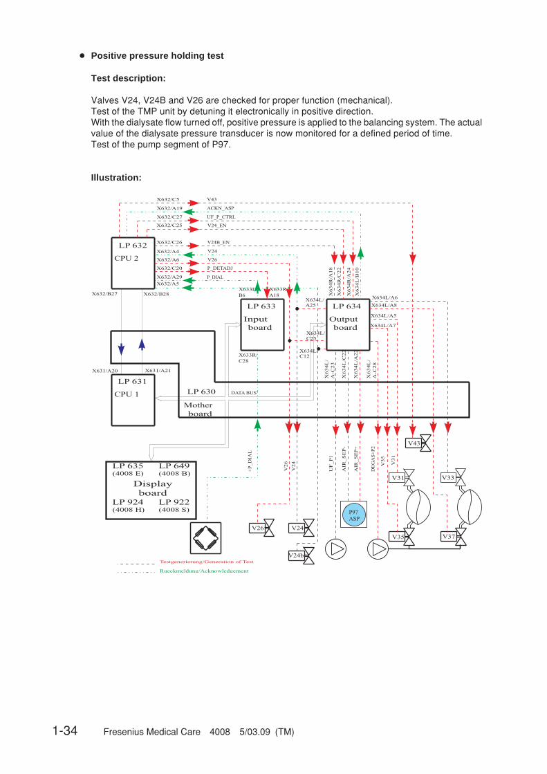
● Positive pressure holding test
Test description:
Valves V24, V24B and V26 are checked for proper function (mechanical).Test of the TMP unit by detuning it electronically in positive direction.With the dialysate flow turned off, positive pressure is applied to the balancing system. The actualvalue of the dialysate pressure transducer is now monitored for a defined period of time.Test of the pump segment of P97.
Illustration:

Fresenius Medical Care 4008 5/03.09 (TM) 1-35
Error description:
Error message Description
F01 pos. Pressure The mandatory filling program of CPU1 has not been completed (10sec).– The solenoid valve V43 is not closed.
F24 pos. Pressure V24 valve error.– Acknowledgement (V24, X637/C1) → X632/A4, 24 V are missing.
F25 pos. Pressure No pressure increase above 150 mmHg (change in pressure) aftervalve switching.– Control signals of V24 and V24B mistaken for each other.– Leakage in the external system (shunt interlock, dialysate lines,
etc.).– If the HDF filter test was skipped: Clamp the HDF filter.
F26 pos. Pressure No pressure compensation after opening of V43 (–125 mmHg to55 mmHg).– V24 got stuck (mechanically open).– V43 not open.– V26 leaking.
F27 pos. Pressure No pressure compensation after opening of V43 (–125 mmHg to55 mmHg).– V24 got stuck (mechanically open).– V43 not open.– V189 (retentate valve) leaking.
F02 pos. Pressure The loading pressure cannot be measured via the solenoid valve V26 inthe hydraulic system (P-Dial. < 600 mmHg, 15 sec).– Solenoid valve V26 mechanically not open.– Solenoid valve V43 mechanically not closed.The balancing chamber is switched to passage during this test sequence. V24, V24Band V43 are closed; V26 is open.
F03 pos. Pressure The hydraulic system cannot be deaerated via the solenoid valve V43;the zero point of –125 to 55 mmHg has not been reached (15 sec).– Solenoid valve V26 mechanically not closed.– Solenoid valve V43 mechanically not open.– Zero point outside the –125 to 55 mmHg range.The balancing chamber is switched to passage during this test sequence. V24, V24Band V26 are closed; V43 is open.
F04 pos. Pressure The first working point (220 digits) of the differential amplifier cannot beset.– Pressure variations are too large.– The D-A converter (IC11) on P.C.B. LP 632 is defective.– The operational amplifier (IC1/IC3) on P.C.B. LP 632 is defective.– The acknowledgement (P_DIAL, X633L/B6) → X632/A29 is defec-
tive.
1-36 Fresenius Medical Care 4008 5/03.09 (TM)
F05 pos. Pressure Test detuning results in a change in the measuring range of more than95 mmHg (60 sec).– The operational amplifier (IC2) on P.C.B. LP 632 is defective.– Acknowledgement (P_DIAL, X633L/B6) → X632/A29, change in
voltage too large.– Detuning defective (P_DETADJ, X632/C20) → X633R/C22.– The balancing chamber valve V36 or V38 (waste water valve) is
leaky.
F06 pos. Pressure Test detuning results in a change in the measuring range of less than85 mmHg (60 sec).– The D-A converter (IC11) on P.C.B. LP 632 is defective.– Acknowledgement (P_DIAL, X633L/B6) → X632/A29, change in
voltage insufficient.– Detuning defective (P_DETADJ, X632/C20) → X633R/C22.– V26 is leaky.
F07 pos. Pressure After detuning in the test there is a difference (P.diff > ±9 mmHg)between the display and the differential amplifier.– The voltage divider R23/R9 or the operational amplifier IC2 is
defective.– The operational amplifier IC1/IC3 is defective.– The balancing chamber valve V36 or V38 (waste water valve) is
leaky.
F08 pos. Pressure Test detuning results in a change in the measuring range of more than400 mmHg (20 sec).– The operational amplifier (IC2) on P.C.B. LP 632 is defective.– Acknowledgement (P_DIAL, X633L/B6) → X632/A29, change in
voltage too large.– Detuning defective (P_DETADJ, X632/C20) → X633R/C22.
F09 pos. Pressure Test detuning results in a change in the measuring range of less than350 mmHg (20 sec).– The D-A converter (IC11) on P.C.B. LP 632 is defective.– Acknowledgement (P_DIAL, X633L/B6) → X632/A29, change in
voltage insufficient.– Detuning defective (DIAL_DET_ADJ, X632/C20) → X633R/C22.
F10 pos. Pressure The second working point (116 digits) of the difference amplifier cannotbe set correctly.– The D-A converter (IC11) on P.C.B. LP 632 is defective.– The operational amplifier (IC1/IC3) on P.C.B. LP 632 is defective.
F11 pos. Pressure Change in the dialysate pressure after closing of the solenoid valve V43(zero point change from –20 mmHg to +80 mmHg within 15 sec).– The solenoid valve V24B is not closed.– The balancing chamber valve V36 or V38 (waste water valve) is
leaky.The balancing chamber is switched to passage during this test sequence. V43, V24Band V26 are closed; V24 is open.

Fresenius Medical Care 4008 5/03.09 (TM) 1-37
F12 pos. Pressure The loading pressure cannot be measured via the solenoid valves V24and V24B in the hydraulic system (P-Dial. < 600 mmHg, 15 sec).– Solenoid valve V24 or V24B mechanically not open.The balancing chamber is switched to passage during this test sequence. V43 and V26are closed; V24 and V24B are open.
F13 pos. Pressure The hydraulic system cannot be deaerated via the solenoid valve V43(P-Dial. not equal to –125 to 55 mmHg, 20 sec).– The solenoid valve V24 is not closed.– V43 neither opens electrically nor mechanically.The balancing chamber is switched to passage during this test sequence. V24 and V26are closed; V24B and V43 are open.
F14 pos. Pressure Zero point change after closing of solenoid valve V43 (20 sec).Standard: P-Dial. not equal to –125 to 55 mmHg.HDF option: P-Dial. not equal to –125 to 60 mmHg.– The solenoid valve V24 is not closed.The balancing chamber is switched to passage during this test sequence. V24, V26 andV43 are closed; V24B is open.
F15 pos. Pressure The loading pressure is below 780 mmHg ±30 mmHg (10 sec).– The loading pressure is too low.
F16 pos. Pressure During the start phase, the pressure dropped below 620 mmHg (meas-uring tolerance: ±30 mmHg, max. test running time 120 sec).– Major leakage in the hydraulic system.– The UF pump spring is defective.– The loading pressure is too low.– The air separation pump fails to occlude.– Relief valve (78) or V43 is leaky.
F17 pos. Pressure During the start phase, it was not possible to reduce the dialysatepressure to a value below 760 mmHg (measuring tolerance:±30 mmHg, test running time 120 sec).– The loading pressure is too high.– The UF pump is defective.
F18 pos. Pressure The working point (116 digits) of the differential amplifier cannot be setcorrectly (test running time 120 sec).– The pressure variations in the system are too large.
F19 pos. Pressure Completion of the pressure measurement was not possible (max. testrunning time 120 sec).– The D-A converter (IC11) on P.C.B. LP 632 is defective.– The acknowledgement (P_DIAL, X633L/B6) → X632/A29 is defec-
tive.

1-38 Fresenius Medical Care 4008 5/03.09 (TM)
F20 pos. Pressure The positive pressure holding test failed to be passed. While the flowwas off, a pressure drop of more than ±80 mmHg/min was detected inthe hydraulic system.– Leakage in the hydraulic system.– The UF pump spring is defective.– ASP fails to occlude.– Relief valve leaking.– V84 leaking.
F21 pos. Pressure The dialysate pressure cannot be set to a value between 460 and760 mmHg ±30 mmHg (10 sec).– The heat exchanger is defective.– Problem in the hydraulic system.
F22 pos. Pressure The air separation pump is not running during the test phase (2 sec).– Control line (AIR_SEP+, X634L/A22) → ASP/..., 24 V are missing.– Control line (AIR_SEP–, X634L/C22) → ASP/..., 0 V are missing.– Acknowledgement (ACKN_ASP, X634L/B10) → X632/A19, 12 V
are missing.
F23 pos. Pressure Pressure drop in the hydraulic system during the measurement phase(8 sec). Change more than +4 digits or more than –8 digits.– Leakage in the pump segment of the air separation pump.– Leakage in the heat exchanger.– Acknowledgement (P_DIAL, X633L/B6) → X632/A29, change in
voltage too large.
F24 – F27 See between F01 and F02
F28 pos. Pressure ASP functional test (running and delivery test)– ASP line segment is occluded– ASP line segment has been incorrectly inserted (check direction of
delivery)– ASP is not running (electrically or mechanically)– V87 electrically or mechanically closed
F95 pos. Pressure System error.

Fresenius Medical Care 4008 5/03.09 (TM) 1-39
● UF function test
Test description:
CPU1 activates the UF pump at a defined rate.CPU2 checks the UF pump.CPU2 blocks the control line of the UF pump and checks whether the UF pump stops.Check of the UF counter.
The following is additionally applicable with built-in 4008 HDF option:CPU1 activates the UF pump 2 at a defined rate.CPU2 checks the hydraulic and the electric function of the UF pump 2.CPU2 blocks the control line of the UF pump 2 and checks whether it stops.Check of the UF2 counter.
Illustration:
+P
_D
IAL
X633R/C28
UF_P1
UF_P_EN
Rueckmeldung/Acknowledgement
Testgenerierung/Generation of Test
DATA BUS
Mother
LP 630
board
Output
LP 634
boardboardInput
LP 633
X632/B27 X632/B28
X631/A20 X631/A21
X632/A7
X632/C28
A22
CPU 2
LP 632
CPU 1
LP 631
UF
_P
1
X632/C27 UF_P_CTL
UF_P2CTL
P_DIALX632/B24X632/A29
C11
X634R/A24
X634R/ X634R/
UF
_P
2(n
ur
bei
40
08
HD
F)
X632/C7 UF_P2
A-C23A-C24X634L/ X634L/X633L/
X633L/
X633L/C23 C14
B6
..
LP 635(4008 E)
LP 649(4008 B)
LP 922(4008 S)
LP 924(4008 H)
Displayboard

1-40 Fresenius Medical Care 4008 5/03.09 (TM)
Error description:
Error message Description
F01 UF-Function The pause between the strokes of the UF pump 1 was shorter than220 ms. Correct volume delivery is not ensured due to too short areturn.– CPU1 issued too high a pump rate.
F02 UF-Function The pulse time for the UF pump 1 is shorter than 180 ms. Correctvolume delivery is not ensured due to too short an emission time.– The monoflop on P.C.B. LP 634 is defective (IC42/R82/C47).
F03 UF-Function The pulse time for the UF pump 1 is longer than 500 ms. A maximumrate of 5000 ml/h is not possible.– The monoflop on P.C.B. LP 634 is defective (IC42/R82/C47).
F04 UF-Function No activity of the UF pump 1 during the test (5 sec).– Acknowledgement (UF_P1, X637/B23) → X632/A7, no LOW puls-
es.– Control line (UF_P1, X634L/ABC23) → X637/B23, no LOW pulses.
F05 UF-Function The UF pump 1 cannot be stopped by CPU2.– Control line (UF_P_EN, X632/C28) → X634R/A22, 5 V are missing.– The reset input at IC42/pin 3 on P.C.B. LP 634 is defective.
F06 UF-Function The UF pump acknowledgement of CPU1 is defective.– Acknowledgement (UF_P1, X637/B23) → X622L/C14, no LOW
pulses.
F07 UF-Function The change in pressure after a stroke is less than 20 mmHg.– The UF pump 1 is mechanically defective.– Control line (UF_P1_CTL, X632/C27) → X634R/A24, no LOW
pulse.
F09 UF-Function Dialysate pressure is outside the measuring range (15s).– UF pressure transducer defective– D/A converter (IC11) on P.C.B. LP 632 defective– Operational amplifier (IC1/IC3) on P.C.B. LP 632 defective
F11 UF-Function The pause between the strokes of the UF pump 2 was shorter than 220ms. Correct volume delivery is not ensured due to too short a return.– CPU1 issued too high a pump rate.
F12 UF-Function The pulse time for the UF pump 2 is shorter than 180 ms. Correctvolume delivery is not ensured due to too short an emission time.– The monoflop on P.C.B. LP 634 is defective (IC42/R65/C45).
Fresenius Medical Care 4008 5/03.09 (TM) 1-41
F13 UF-Function The pulse time for the UF pump 2 is longer than 500 ms. A maximumrate of 5000 ml/h is not possible.– The monoflop on P.C.B. LP 634 is defective (IC42/R65/C45).
F14 UF-Function No activity of the UF pump 2 during the test (4 sec).– Acknowledgement (UF_P2, X637/B26) → X632/C7, no LOW puls-
es.– Control line (UF_P2, X634L/ABC24) → X637/B26, no LOW pulses.
F15 UF-Function The UF pump 2 cannot be stopped by CPU2.– Control line (UF_P_EN, X632/C28) → X634R/A22, 5 V are missing.– The reset input at IC42/pin 13 on P.C.B. LP 634 is defective.
F16 UF-Function The UF pump acknowledgement of CPU1 is defective.– Acknowledgement (UF_P2, X637/B26) → X633L/C23, no LOW
pulses.
F09 UF-Function Dialysate pressure is outside the measuring range (15s).– UF pressure transducer defective– D/A converter (IC11) on P.C.B. LP 632 defective– Operational amplifier (IC1/IC3) on P.C.B. LP 632 defective
F17 UF-Function The change in pressure after a stroke of the UF pump 2 is less than 20mmHg.– The UF pump 2 is mechanically defective.– Control line (UF_P2_CTL, X632/B24) → X634R/C11, no HIGH
pulse.
F20 UF-Function The difference in volume between UF pump 1 and UF pump 2 is higherthan 25% (range of tolerance 15% to 35%).– The stroke volume of UF pump 1 or UF pump 2 has been misadjust-
ed.
F95 UF-Function System error.
1-42 Fresenius Medical Care 4008 5/03.09 (TM)
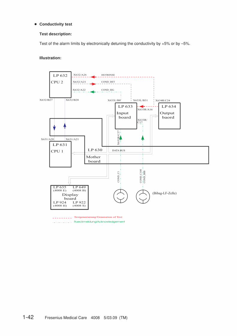
● Conductivity test
Test description:
Test of the alarm limits by electronically detuning the conductivity by +5% or by –5%.
Illustration:
COND_SIG
Rueckmeldung/Acknowledgement
Testgenerierung/Generation of Test
DATA BUS
Mother
LP 630
board
Output
LP 634
baordboard
Input
LP 633
CO
ND
_C
1
CO
ND
_C
108
CO
ND
_B
IB
X632/A22
X632/B27 X632/B28
X631/A20 X631/A21
X633R
/C
27
X633L/B31
X633R/A16
X633R/
C17
X633L/B8
CPU 2
LP 632
CPU 1
LP 631
COND_DETX632/A21
(Bibag-LF-Zelle)
7b
HOTRINSEX632/A26
X634R/C24
LP 635
(4008 E)
LP 649
(4008 B)
LP 922
(4008 S)
LP 924
(4008 H)
Display
board
Fresenius Medical Care 4008 5/03.09 (TM) 1-43
Error description:
Error message Description
F01 Conductivity The conductivity failed to be within the scale limits or to stabilize within10 minutes (±0.1 mS/10 sec).– Concentrate is not connected.– Acknowledgement (COND_SIG, X633L/B8) → X632/A22, voltage
outside the measuring range or unstable.
F02 Conductivity Detuning in positive direction not more than 0.5 mS (10 sec).– Acknowledgement (COND_SIG, X633L/B8) → X632/A22 insuffi-
cient.– Detuning (COND_DET, X632/A21) → X633L/B31 insufficient.
F03 Conductivity Detuning in negative direction not more than 0.5 mS (10 sec).– Acknowledgement (COND_SIG, X633L/B8) → X632/A22 insuffi-
cient.– Detuning (COND_DET, X632/A21) → X633L/B31 insufficient.
F04 Conductivity The conductivity cell indicates a constant value.– The CD cell is defective.
F05 Conductivity CPU1 failed to transmit a Bibag status message within 3 sec.– Run-time problem (software).
F08 Conductivity CPU 1 fails to increase the working point (when the conductivity is<40mS/cm uncompensated) for the bibag conductivity by > 5 digits.– Detuning (HOT_RINSE, X634R/C24 → X633R/A16) not 12V– P.C.B. LP 633 T2 or IC26 defective
F06 Conductivity The Bibag CD detuning is not more than 1 mS/cm.– Acknowledgement (COND_SIGNAL3, X633R/A12) → MP TP3 on
P.C.B. LP 633, change in voltage insufficient.– Detuning (COND_DET, X632/A21) → X633L/B31 insufficient.
F07 Conductivity The Bibag CD display is outside of the measuring range.– Acknowledgement (COND_SIGNAL3, X633R/A12) → MP TP3 on
P.C.B. LP 633.– Conductivity outside the expected detuning range caused by wrong
concentrate on the bicarbonate port or temperature too low.
F95 Conductivity System error.
1-44 Fresenius Medical Care 4008 5/03.09 (TM)
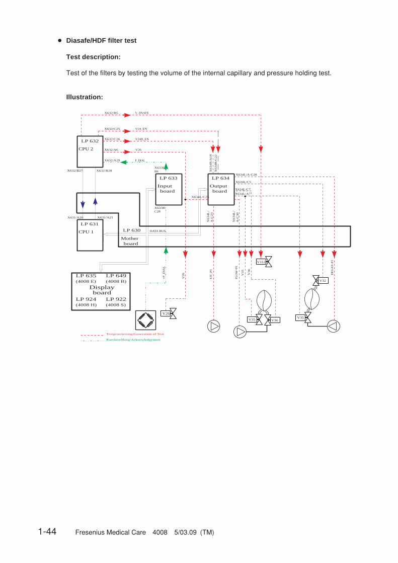
● Diasafe/HDF filter test
Test description:
Test of the filters by testing the volume of the internal capillary and pressure holding test.
Illustration:
Rueckmeldung/Acknowledgement
Testgenerierung/Generation of Test
P_DIAL
DATA BUS
Mother
LP 630
board
Output
LP 634
boardboardInput
LP 633
X632/B27 X632/B28
X631/A20 X631/A21
V26
X632/C25
X632/A29
B6
UF
_P
1
V24_EN
CPU 2
LP 632
CPU 1
LP 631
FL
OW
+P
1
DE
GA
S+
P1
V35
V2
6
+P
_D
IAL
V3
6
X634L/C7
X634L/A7
X634L/C5
X634L/A-C28
A-C
23
V112
V36V35V35
V32
X632/B5 V_DSAFE
V26X632/A6
X632/C26 V24B_EN
X633L/
X633R/C28
X6
34
R/C
22
X6
34
L/
X634L
/A
-C3
0
X6
34
R/A
18
X634L/C25 ..
LP 635(4008 E)
LP 649(4008 B)
LP 922(4008 S)
LP 924(4008 H)
Displayboard
Fresenius Medical Care 4008 5/03.09 (TM) 1-45
Error description:
Error message Description
F02 Diasafe The balancing chamber was not stopped by CPU1 (24 sec).– The message via the serial interface from CPU1 to CPU2 is missing.– The current rise pulse is missing (CI, X634R/A23) → X633L/C31, no
5-V pulse.
F04 Diasafe CPU1 failed to complete one balancing chamber switching within 20sec (30 ml fluid not removed?).– The message via the serial interface from CPU1 to CPU2 is missing.– The current rise pulse is missing (CI, 634R/A23) → 633L/C31, no 5-
V pulse.
F06 Diasafe During the pressure built-up phase, a negative pressure of less than–450 mHg has developed (24 sec).– Diasafe valve not open, control line (V_DSAFE, X632/B5) → X637/
C16, 0 V are missing.
F07 Diasafe After the maximum fluid volume of 145 ml + 30 ml has been removed,the expected negative pressure of –300 mmHg to –450 mm Hg failed tobuild up.– Major leakage in the Diasafe filter membrane and/or filter housing.– Major leakage in the O-rings on filter holder/couplings.– V26 electrically or mechanically not closed.
F08 Diasafe The negative test pressure of more than –300 mmHg has developedbefore the minimum fluid removal of 145 ml –30 ml has been achieved.– The Diasafe filter is contaminated.– The Diasafe filter was not correctly deaerated upon start of the test.– V112 electrically or mechanically not open.
F09 Diasafe The zero point for pressure measurement cannot be set. The maximumtest time has been exceeded (max. test time 5 min).– Leakage in the Diasafe filter membrane and/or filter housing.– Leakage in the O-rings on filter holder/couplings.– P.C.B. LP 632, IC3/pin 12 not in socket or IC defective (differential
amplifier).
F10 Diasafe The negative pressure to be achieved in the test failed to stabilizewithin the maximum test time of 5 minutes (change > ±16.7 mmHg/min).– Leakage in the Diasafe filter membrane and/or filter housing.– Leakage in the O-rings on filter holder/couplings.– Leakage in the hydraulic system.– V 26 electrically or mechanically not closed.
F20 Diasafe It was not possible to prime (deaerate) the dialysate filter within 2minutes.– Flow problems.– The priming program is permanently active (level sensor, osmosis
water, or P.C.B. LP 633, IC36 defective).
F95 Diasafe System error.

1-46 Fresenius Medical Care 4008 5/03.09 (TM)
Error message Description
F01 HDF-Filter The Diasafe option has not been set although ON-LINE HDF has beenselected.– CPU 2: DIP switch array 2, switch 1 not set to ON.
F02 HDF-Filter CPU1 failed to stop the balancing chamber (24 sec).– The message via the serial interface from CPU1 to CPU2 is missing.– The current rise pulse is missing (CI, X634/A23) → X633L/C31, no
5-V pulse.
F04 HDF-Filter CPU1 failed to comlete one balancing chamber switching within 20 sec(30 ml fluid not removed?).– The message via the serial interface from CPU1 to CPU2 is missing.– Verify the current rise pulse.
F06 HDF-Filter During the pressure-buildup phase, a negative pressure of less than–370 mmHg has developed (24 sec).– The HDF filter is clamped/clogged.– The Diasafe valve is not open, control line (V_DSAFE, X632/B5) →
X637/C16, 0 V are missing.
F07 HDF-Filter After the maximum fluid volume of 255 ml +60 ml has been removedthe expected negative pressure of –220 mmHg up to 370 mmHg failedto build up.– Major leakage in the Diasafe/HDF filter membrane and/or filter
housing.– Major leakage in the O-rings on filter holder/couplings.– V26 electrically or mechanically not closed.
F08 HDF-Filter The negative test pressure of less than –220 mmHg has developed,before the minimum fluid removal of 255 ml –60 ml has been achieved.– The Diasafe/HDF filters are contaminated.– The Diasafe/HDF filters were not correctly deaerated upon start of
the test.– V112 electrically or mechanically not open.
F09 HDF-Filter The zero point for pressure measurement cannot be set. The max. testtime has been exceeded (10 min).– Leakage in the Diasafe/HDF filter membrane and/or filter housing.– Leakage in the O-rings on filter holder/couplings.
F10 HDF-Filter The negative pressure to be achieved in the test failed to stabilizewithin the maximum test time of 10 minutes (change >±13.3 mmHg/min).– Leakage in the Diasafe/HDF filter membrane and/or filter housing.– Leakage in the O-rings on filter holder/couplings.– Leakage in the hydraulic system.– V26 electrically or mechanically not closed.
Fresenius Medical Care 4008 5/03.09 (TM) 1-47
F20 HDF-Filter It was not possible to prime (deaerate) the Diasafe filter within2 minutes.– Flow problems.– The priming program is permanently active (level sensor, osmosis
water, or P.C.B. LP 633, IC36 defective).
F21 HDF-Filter It was not possible to correctly rinse/prime the HDF filter within5 minutes (before the test).– Flow problems.– No conductivity.– Conductivity at the upper or lower end of the scale range.– The HDF pump is not running (e.g. open door).– The delivery rate of the HDF pump is less than 380 ml/min.– Line diameter not set to 8 mm.– NTC6 permanently fails to detect fluid.– Sieve on V43 clogged.
F22 HDF-Filter It was not possible to correctly rinse/prime the HDF filter within5 minutes (after the test).– Flow problems.– No conductivity.– Conductivity at the upper or lower end of the scale range.– Especially with biBag systems: check filter on V43– The HDF pump is not running (e.g. open door).– The delivery rate of the HDF pump is less than 380 ml/min.– Line diameter not set to 8 mm.– NTC6 permanently fails to detect fluid.– Sieve on V43 clogged.
F95 HDF-Filter System error.

1-48 Fresenius Medical Care 4008 5/03.09 (TM)
● Online plus / Diasafe plus filter / HPU test
F01 ONLINE plusF01 DIASAFE plusF01 HPU Present options and DIP switch settings do not match.
CPU1 system status (MST), HPU status and DIP switch/Array2changed during the test running time.– ONLINE plus:
CPU 2: Array 2, DipSw2 not set to OFFCPU 2: Array 2, DipSw3 not set to ON
– DIASAFE plus:CPU 2: Array 2, DipSw2 not set to OFFCPU 2: Array 2, DipSw3 not set to OFF
– MST transmitted by CPU1 not matching with the set DIP switch ofarray 2.
– DIP switch/Array2 changed while the test was in progress.– HPU logged off.
F34 ONLINE plusF34 DIASAFE plus Pressure holding test not passed. Max. number of treatments exceed-
ed?– Diasafe and HDF filter membranes leaking/worn.
F02 ONLINE plusF02 DIASAFE plusF02 HPU Dialysate outlet pressure (DA1) outside the permissible range (10s).
DA1 test range: –125mmHg ≤ P_dial ≤ 55 mmHg– Acknowledgement DA 1 (P_DIAL, X633L/B6) → X632/A29– Acknowledgement line DA 2 (see HPU diagram)
F03 ONLINE plusF03 DIASAFE plusF03 HPU Cross comparison of both pressure transducers (DA1 / DA2) is outside
the acceptable tolerance (10s).P(DA2) == P(DA1) ±20mmHg– Acknowledgement DA 1 (P_DIAL, X633L/B6) → X632/A29– Acknowledgement DA 2 (see HPU diagram)
F41 ONLINE plusF41 DIASAFE plusF41 HPU The test valve V183 is leaking. Pressure increase in the system of
ΔP(DA2) > 30 mmHg within 4s.– V183 open, contaminated, or mechanically defective– HPU, output stage etc. defective
F42 ONLINE plusF42 DIASAFE plusF42 HPU No pressure increase of ΔP(DA2) > 200 mmHg within 4s after opening
the test valve V183 in the system.– V183 fails to open or mechanically defective.– Air pump defective, is not running– HPU, V183 and/or air pump output stage etc. defective
Fresenius Medical Care 4008 5/03.09 (TM) 1-49
F43 ONLINE plusF43 DIASAFE plusF43 HPU The lower pressure test range of ΔP(DA2) > 300 mmHg failed to be
achieved within 1s after closing the test valve V183.– HPU, output stage etc. defective– ONLINE filter leaking
F44 ONLINE plusF44 DIASAFE plusF44 HPU The upper pressure test range of ΔP(DA2) 750 mmHg was exceeded
within 4s after closing of the test valve V183.– HPU, output stage etc. defective
F04 ONLINE plusF04 DIASAFE plus The air pump is running although valve V43 is closed.
– HPU, output stage etc. defective
F05 ONLINE plus The door on the Online Sys module is open during the rate test.– Close module door.
F06 ONLINE plus Port 1 is open during the first pressure build-up phase.– Close port 1 (substituate port).
F07 ONLINE plus Port 2 is open during the first pressure build-up phase.– Close port 2 (rinse port).
F08 ONLINE plus Failure to reach the test pressure PDIAL2 > 795 mmHg within 12s.– Calibrate dialysate pressure.– Replace DA 2 (re-calibration required)– Air pump (185) or test valve (V183) defective– Hydraulic system or valve ONL3 (191) leaking– Air pump control (185) based on V43 status defective (HPU defec-
tive)
F09 ONLINE plus The ONLINE system pump failed to comply with the first test rate of100 ml/min ± 9 ml/min.– ONLINE system pump control defective
F10 ONLINE plus Monitoring unit (Hall sensor) of the pump rotor detects incorrect rotationof the rotor (desired rate 300 ml/min ± 25%).– ONLINE system pump control defective (outside the tolerance of
±25%)– Hall sensor /electronics defective
F11 ONLINE plus The ONLINE system pump failed to comply with the second test rate of300 ml/min ± 9 ml/min.– ONLINE system pump control defective
F12 ONLINE plus After the ONLINE system pump was switched off in the test, themonitoring unit (Hall sensor) detects that the rotor failed to stop correct-ly.– Pump stop (output stage) defective– Hall sensor /electronics defective
1-50 Fresenius Medical Care 4008 5/03.09 (TM)
F13 ONLINE plus After the ONLINE system pump was switched off in the test, the actualrate of the module is > 0 ml/min.– Pump stop (output stage) defective– Synchro-transmitter electronics defective
F14 ONLINE plus After activation of the substituate pump the monitoring unit (Hall sen-sor) of the pump rotor detects incorrect rotation of the rotor (desiredrate 300 ml/min).– Pump control defective (outside the tolerance of ±25%)– Hall sensor /electronics defective
F15 ONLINE plus After activation of the substituate pump the system pump failed tocomply with the test rate of 300 ml/min ±9ml/min.– Pump control defective
F16 ONLINE plus Port 1 open during ONL valve test sequence.– Close port 1 (substituate port).
F17 ONLINE plus Port 2 open during ONL valve test sequence.– Close port 2 (rinse port).
F18 ONLINE plus Acknowledgement of ONL1 (V193) differs from the desired state of thevalve.– Valve control in the ONLINE Sys module defective– Valve acknowledgement in the ONLINE Sys module defective
F19 ONLINE plus Acknowledgement of ONL2 (V192) differs from the desired state of thevalve.– Valve control in the ONLINE Sys module defective– Valve acknowledgement in the ONLINE Sys module defective
F20 ONLINE plus Acknowledgement of ONL3 (V191) differs from the desired state of thevalve.– Valve control in the ONLINE Sys module defective– Valve acknowledgement in the ONLINE Sys module defective
F21 ONLINE plus Leakage test ONL3 (V191) failed to be passed.The permitted pressure drop of ΔP < –10 mmHg has been exceeded orthe test pressure is P ≤ 710 mmHg.– Valve ONL3 (V191) in the ONLINE Sys module leaking– Leaking system / tubing connections– Port 1 or 2 in the ONLINE Sys module leaking
F22 ONLINE plus Leakage test ONL2 (V192) failed to be passed.The permitted pressure drop of ΔP < –10 mmHg has been exceeded orthe test pressure is P ≤ 710 mmHg.– Valve ONL2 (V192) in the ONLINE Sys module leaking– Leaky system /tubing connections– Port 1 in the ONLINE Sys module leaking
F23 ONLINE plus Leakage test ONL1 (V193) failed to be passed.The permitted pressure drop of ΔP < –10 mmHg has been exceeded orthe test pressure is P ≤ 710mmHg.– Valve ONL1 (V193) in the ONLINE Sys module leaking– Leaky system /tubing connections

Fresenius Medical Care 4008 5/03.09 (TM) 1-51
F24 ONLINE plus After the valves ONL1 to 3 opened, the pressure drop in the systemwas insufficient (ΔP < –100 mmHg).– Valve ONL1/ONL2/ONL3 electrically or mechanically not open– Kinked tubing– HDF filter strongly contaminated
F25 ONLINE plus No pressure change of ΔP > 40 mmHg within 15s.– HDF filter membrane leaking (major leakage)– No HDF filter installed
F26 ONLINE plusF26 DIASAFE plus Insufficient test pressure (P < 750mmHg) in the system.
– HDF filter membrane leaking (major leakage)– No HDF filter installed– Hydraulics system leaking
F27 ONLINE plusF27 DIASAFE plus After the valve V189 opened, the pressure drop in the system was
insufficient (ΔP < –70 mmHg).– Valve V189 electrically or mechanically not open– Diasafe filter strongly contaminated– Filter before/after V43 strongly contaminated
F28 ONLINE plusF28 DIASAFE plus Pressure increase in the system fails to exceed P > 760 mmHg.
– Diasafe filter membrane leaking (major leakage)– No Diasafe filter installed
F29 ONLINE plusF29 DIASAFE plus Pressure holding test failed to be passed. Excess pressure drop within
a measurement time of 30s (ΔP > –10 mmHg).– Diasafe and/or HDF filter membrane leaking
F30 ONLINE plusF30 DIASAFE plus During the pressure holding test valve(s) ONL1, 2 or 3 and/or V189 was
(were) closed (according to electronic acknowledgement).– Valve control failed
F31 ONLINE plusF31 DIASAFE plusF31 HPU Fill phase has been stopped.
Valve(s) V26 open and/or V24, V24b closed (according to electronicacknowledgement), or failure to perform 25 or 15 balancing chamberswitchings within 120s.– Valve control failed– Balancing chamber switchings failed (e.g. only “Eigentakt”)
F32 ONLINE plus Valve(s) ONL1, 2 or 3 closed and/or V24 open or port 1 or 2 open duringthe rinse phase (according to electronic acknowledgement).– Valve control failed– Operator opened ports too early.
1-52 Fresenius Medical Care 4008 5/03.09 (TM)
F33 ONLINE plus Rinse phase has been aborted.Valve V189 open (according to electronic acknowledgement), or failureto perform 34 balancing chamber switchings within 240s.– Valve control failed– Failure to detect current rise pulse– Conductivity not within the scale range
Possible cause: Concentrate and/or bicarbonate level sensor do notrecognize CD, although present.
F34 ONLINE plusF34 DIASAFE plus See error message between F01 and F02 ONLINE plus /DIASAFE plus
F41 ONLINE plusF41 DIASAFE plus See error message between F01 and F02 ONLINE plus /DIASAFE plus
F42 ONLINE plusF42 DIASAFE plus See error message between F03 and F04 ONLINE plus /DIASAFE plus
F43 ONLINE plusF43 DIASAFE plus See error message between F03 and F04 ONLINE plus /DIASAFE plus
F44 ONLINE plusF44 DIASAFE plus See error message between F03 and F04 ONLINE plus /DIASAFE plus
F95 ONLINE plusF95 DIASAFE plusF95 HPU System error
Fresenius Medical Care 4008 5/03.09 (TM) 1-53
1.1.4 Description of system errors during the cleaning programs
● V84 monitoring
Error message Description
Rinse Failure F01 End of the rinse-free program in Dis I to V.Conductivity has been recognized via V84, although the valve is stillclosed.This error message can be acknowledged by pressing the Rinse key.
Rinse Failure F21 Disinfectant suction phase in Dis I – IV.Maximum permissible UF pump strokes (160) during the suctionphase) exceeded.Error message cannot be acknowledged.Turn the system off and on again.
Rinse Failure F02 Disinfectant suction phase in Dis I to IV.Conductivity has not been recognized via V84, and the “Disinfectantempty ?” message has been acknowledged twice.This error message cannot be acknowledged.Switch the system off and on again.Program Dis V (only on systems with advanced hydraulics)No conductivity detected via concentrate level sensor, and “Disinfect-ant empty ?” message acknowledged twice.Error message cannot be acknowledged.Turn the system off and on again.
Rinse Failure F03 End of the suction phase in Dis I to IV.Conductivity has been recognized via V84, although the valve is al-ready closed.This error message can be acknowledged by pressing the Disinfectionkey.
Rinse Failure F04 End of the suction phase in Dis I to IV.The float switch does not recognize any fluid after the disinfectant hasbeen drawn in.Aeration of the disinfectant container!This error message cannot be acknowledged.Turn the system off and on again.
F01, F02 and F03 cause the V84 monitoring flag to be set. I.e. after one of these error messageshas occurred, Bergström or ISO-UF dialysis is no longer possible, since it is not possible to switchthe flow off. The V84 malfunction can be eliminated by correctly performing Dis I to IV. Theproblem can also be corrected using the calibration program (by a service technician only), menuitem NOVRAM (Reset V84).
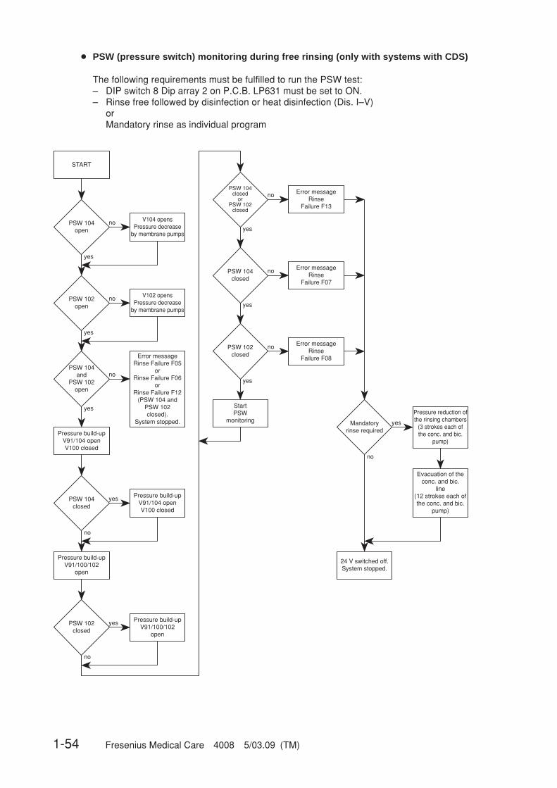
1-54 Fresenius Medical Care 4008 5/03.09 (TM)
● PSW (pressure switch) monitoring during free rinsing (only with systems with CDS)
The following requirements must be fulfilled to run the PSW test:– DIP switch 8 Dip array 2 on P.C.B. LP631 must be set to ON.– Rinse free followed by disinfection or heat disinfection (Dis. I–V)
orMandatory rinse as individual program
PSW 104open
V104 opensPressure decrease
by membrane pumps
no
yes
START
PSW 102open
V102 opensPressure decrease
by membrane pumps
no
yes
PSW 104and
PSW 102open
Error messageRinse Failure F05
orRinse Failure F06
orRinse Failure F12
(PSW 104 and PSW 102 closed).
System stopped.
no
yes
Pressure build-upV91/104 openV100 closed
PSW 104closed
Pressure build-upV91/104 openV100 closed
yes
no
Pressure build-upV91/100/102
open
PSW 102closed
Pressure build-upV91/100/102
open
yes
no
PSW 104closed
orPSW 102
closed
Error messageRinse
Failure F13
no
yes
Error messageRinse
Failure F07
no
yes
Error messageRinse
Failure F08
no
yes
PSW 104closed
PSW 102closed
StartPSW
monitoring Mandatoryrinse required
Pressure reduction of the rinsing chambers
(3 strokes each of the conc. and bic.
pump)
yes
no
Evacuation of theconc. and bic.
line(12 strokes each of the conc. and bic.
pump)
24 V switched off.System stopped.

Fresenius Medical Care 4008 5/03.09 (TM) 1-55
The pressure switches are designed as make contacts.Specifications:Delta pressure switch: Switching point 700 mbar ±20 mbarAlcatel-SEL-pressure switch: Switching range 675 – 805 mbarEnvec pressure switch: Switching range 700 mbar ±20 mbar
Error message Description
Rinse Failure F05 Rinse-free program with following Dis or HDIS or mandatory rinse asindividual program in Dis I to V.It was impossible to open the pressure switch for PSW_104 (S124)(bicarbonate).– Pressure on distribution piping > 500 mbar (according to specifica-
tion, the permissible pressure is max. 500 mbar) pressure peaks ondistribution piping: Frequently occurs in distribution pipings withuser points if e.g. several patients are disconnected simultaneouslyand disinfection is started.
– Switching point of pressure switch too low:Desired value = 700 mbar ± 20 mbar
– Check acknowledgement of pressure switch on P.C.B. LP 633:Bicarbonate: X633L/ A19
Rinse Failure F06 Rinse-free program with following Dis or HDIS or mandatory rinse asindividual program in Dis I to V.It was impossible to open the pressure switch for PSW_102 (S123)(concentrate).– Pressure on distribution piping > 500 mbar (according to specifica-
tion, the permissible pressure is max. 500 mbar) pressure peaks ondistribution piping: Frequently occurs in distribution pipings withuser points if e.g. several patients are disconnected simultaneouslyand disinfection is started.
– Switching point of pressure switch too low:Desired value = 700 mbar ± 20 mbar
– Check acknowledgement of pressure switch on P.C.B. LP 633:Concentrate: X633L/ A20
Rinse Failure F07 Rinse-free program, Dis, HDIS, or mandatory rinse in Dis I to V.Pressure drop during the monitoring phase on PSW_104 (S124) (bicar-bonate) or pressure build-up impossible.– Check switching point of pressure switch– Check loading pressure
(possibly splinter or contamination in orifice 151, remove tube andpurge tube from both ends).
– Check negative pressure and test orifice (89).(For this purpose, remove and purge the tubing from bothends)
– Check check valve (118) and filter (120).– Check CDS valve (104).– Verify tightness of CDS path.– Check acknowledgement of pressure switch on P.C.B. LP 633:
Bicarbonate: X633L/ A19– Cartridge filter upstream of degassing pump clogged or wrong filter
(filter for disinfectant container) installed. Filters can be distin-guished by different adapters.

1-56 Fresenius Medical Care 4008 5/03.09 (TM)
Rinse Failure F08 Rinse-free program, Dis, HDIS, or mandatory rinse in Dis I to V.Pressure drop during the monitoring phase on PSW_102 (S123) (con-centrate) or pressure build-up impossible.– Check switching point of pressure switch.– Check loading pressure.
(possibly splinter or contamination in orifice 151, remove tube andpurge tube from both ends)
– Check negative pressure and orifice (89).(For this purpose, remove and purge the tubing from bothends)
– Check check valve (117) and filter (119).– Check CDS valve (102).– Verify tightness of CDS path.– Check acknowledgement of pressure switch on P.C.B. LP 633:
Concentrate: X633L/ A20– Cartridge filter upstream of degassing pump clogged or wrong filter
(filter for disinfectant container) installed. Filters can be distin-guished by different adapters.
Rinse Failure F09 Five minutes before the end of the mandatory rinse in Dis I to V.Pressure switch PSW_104 (S124) (bicarbonate) or PSW_102 (S123)(concentrate) did not open after pressure reduction.See Rinse Failure F12.
Rinse Failure F12 Rinse-free program with following Dis or HDIS or mandatory rinse asindividual program in Dis I to V.The pressure switches for PSW_104 (S124) (bicarbonate) and forPSW_102 (S123) (concentrate) could not be opened.– Membrane pumps fail to run.– V 102 or 104 fails to open.– Pressure on distribution piping > 500 mbar (according to specifica-
tion, the permissible pressure is max. 500 mbar) pressure peaks ondistribution piping: Frequently occurs in distribution pipings withuser points if e.g. several patients are disconnected simultaneouslyand disinfection is started.
– Switching point of pressure switch too low:desired value = 700 mbar ± 20 mbar
– Check acknowledgement of pressure switch on P.C.B. LP 633:Bicarbonate: X633L/ A19

Fresenius Medical Care 4008 5/03.09 (TM) 1-57
Rinse Failure F13 Rinse-free program with following Dis or HDIS or mandatory rinse asindividual program in Dis I to V.Pressure drop during the monitoring phase on PSW_104 (S124) (bicar-bonate) or PSW_102 (S123) (concentrate) or pressure build-up impos-sible.– Check switching point of pressure switch.– Check loading pressure.
(Possibly splinter or contamination in orifice 151; remove tube andblow through tube from both ends)
– Check negative pressure and orifice (89).(For this purpose, remove and purge the tubing from bothends)
– Check check valve (117/118) and filter (119/120).– Check CDS valve (102/104).– Verify tightness of CDS path.– Check acknowledgement of pressure switch on P.C.B. LP 633:
Bicarbonate: X633L/ A19Concentrate: X633L/ A20
– Cartridge filter upstream of degassing pump clogged or wrong filter(filter for disinfectant container) installed. Filters can be distin-guished by different adapters.
In case of F07, F08 and F13, the “DO NOT SWITCH OFF !!” message can, in addition, bealternately displayed.However, this message is displayed only if a mandatory rinse program is requested, since theconcentrate and bicarbonate lines still have to be emptied before the system is switched off.
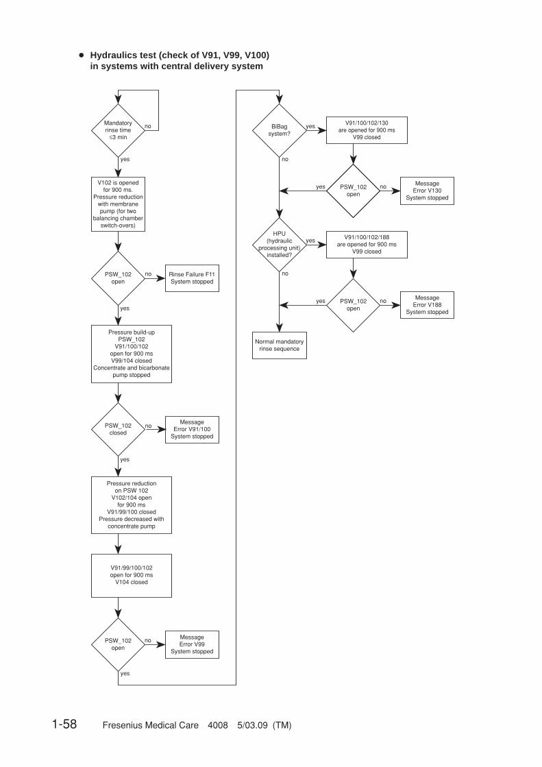
1-58 Fresenius Medical Care 4008 5/03.09 (TM)
● Hydraulics test (check of V91, V99, V100)in systems with central delivery system
Mandatoryrinse time
≤3 min
no
yes
Pressure build-upPSW_102
V91/100/102open for 900 msV99/104 closed
Concentrate and bicarbonate pump stopped
V102 is openedfor 900 ms.
Pressure reductionwith membrane pump (for two
balancing chamberswitch-overs)
PSW_102open
PSW_102closed
MessageError V91/100
System stopped
Rinse Failure F11System stopped
PSW_102open
MessageError V99
System stopped
no
yes
BiBagsystem?
yes
no
PSW_102open
no MessageError V130
System stopped
yes
Normal mandatoryrinse sequence
Pressure reduction on PSW 102
V102/104 open for 900 ms
V91/99/100 closedPressure decreased with
concentrate pump
V91/99/100/102open for 900 ms
V104 closed
no
no
yes
yes
V91/100/102/130 are opened for 900 ms
V99 closed
HPU(hydraulic
processing unit)installed?
yes
no
PSW_102open
no MessageError V188
System stopped
yes
V91/100/102/188are opened for 900 ms
V99 closed
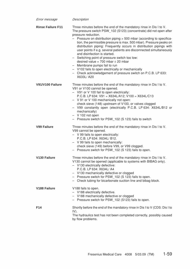
Fresenius Medical Care 4008 5/03.09 (TM) 1-59
Error message Description
Rinse Failure F11 Three minutes before the end of the mandatory rinse in Dis I to V.The pressure switch PSW_102 (S123) (concentrate) did not open afterpressure reduction.– Pressure on distribution piping > 500 mbar (according to specifica-
tion, the permissible pressure is max. 500 mbar). Pressure peaks ondistribution piping: Frequently occurs in distribution pipings withuser points if e.g. several patients are disconnected simultaneouslyand disinfection is started.
– Switching point of pressure switch too low:desired value = 700 mbar ± 20 mbar
– Membrane pumps fail to run– V102 fails to open electrically or mechanically– Check acknowledgement of pressure switch on P.C.B. LP 633:
X633L/ A20
V91/V100 Failure Three minutes before the end of the mandatory rinse in Dis I to V.V91 or V100 cannot be opened.– V91 or V 100 fail to open electrically:
P.C.B. LP 634: V91 = X634L/A12; V100 = X634L/C13– V 91 or V 100 mechanically not open:
check sieve (148) upstream of V100, or valves clogged– V99 constantly open (electrically P.C.B. LP 634: X634L/B12 or
mechanically)– V 102 not open– Pressure switch for PSW_102 (S 123) fails to switch
V99 Failure Three minutes before the end of the mandatory rinse in Dis I to V.V99 cannot be opened.– V 99 fails to open electrically:
P.C.B. LP 634: X634L/ B12.– V 99 fails to open mechanically:
check sieve (149) before V99, or V99 clogged.– Pressure switch for PSW_102 (S 123) fails to open.
V130 Failure Three minutes before the end of the mandatory rinse in Dis I to V.V130 cannot be opened (applicable to systems with BIBAG only).– V130 electrically defective:
P.C.B. LP 634: X634L/ A4– V130 mechanically defective or clogged– Pressure switch for PSW_102 (S 123) fails to open.– Check tubing for bicarbonate suction line and bibag block.
V188 Failure V188 fails to open.– V188 electrically defective.– V188 mechanically defective or clogged– Pressure switch for PSW_102 (S123) fails to open.
F14 Shortly before the end of the mandatory rinse in Dis I to V (CDS: Dis I toIV).The hydraulics test has not been completed correctly, possibly causedby flow problems.
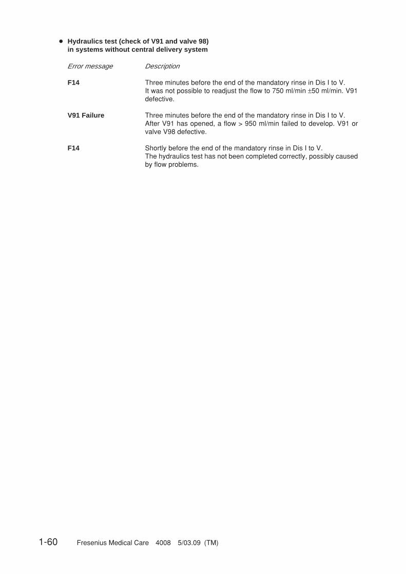
1-60 Fresenius Medical Care 4008 5/03.09 (TM)
● Hydraulics test (check of V91 and valve 98)in systems without central delivery system
Error message Description
F14 Three minutes before the end of the mandatory rinse in Dis I to V.It was not possible to readjust the flow to 750 ml/min ±50 ml/min. V91defective.
V91 Failure Three minutes before the end of the mandatory rinse in Dis I to V.After V91 has opened, a flow > 950 ml/min failed to develop. V91 orvalve V98 defective.
F14 Shortly before the end of the mandatory rinse in Dis I to V.The hydraulics test has not been completed correctly, possibly causedby flow problems.

Fresenius Medical Care 4008 5/03.09 (TM) 1-61
● Hydraulics test (check of V91, V99, V100, V130)in systems with BIBAG and without central delivery system
The following requirements must be fulfilled to run the hydraulics test:
1.The test is run during the last 3 minutes of the mandatory rinse program only.2.DIP switch 7 DIP array 2 on PCB LP 631 must be set to ON.
Mandatoryrinse time
≤3 min
no
yes
Pressureswitchopen
Rinse Failure F15Program stopped
no
yes
Pressure build-upV91 open
V100 closed
Pressure reductionby bic. pump
(performed 5x)
Pressureswitchclosed
V91 FailureProgram stopped
no
yes
Pressure reductionvia V100
by conc. pump(performed 8x)
Pressureswitchopen
V100 FailureProgram stopped
no
yes
Pressure build-upV91/100 open
Pressureswitchclosed
Rinse Failure F16Program stopped
no
yes
Pressure reductionvia V99
Pressureswitchopen
Error V99Program stopped
no
yes
Pressure build-upV91 open
V100 closed
Pressureswitchclosed
Rinse Failure F17Program stopped
no
yes
Pressure reductionvia V130
Pressureswitchopen
V130 FailureProgram stopped
no
yes
no
Test completed
HPU(hydraulic
processing unit)installed?
yes
Pressure build-upV91/100 open
Pressure switchclosed
Rinse Failure F20Program stopped
no
yes
Pressure reductionvia V188
Pressureswitchopen
Rinse Failure V188Program stopped
no
yes
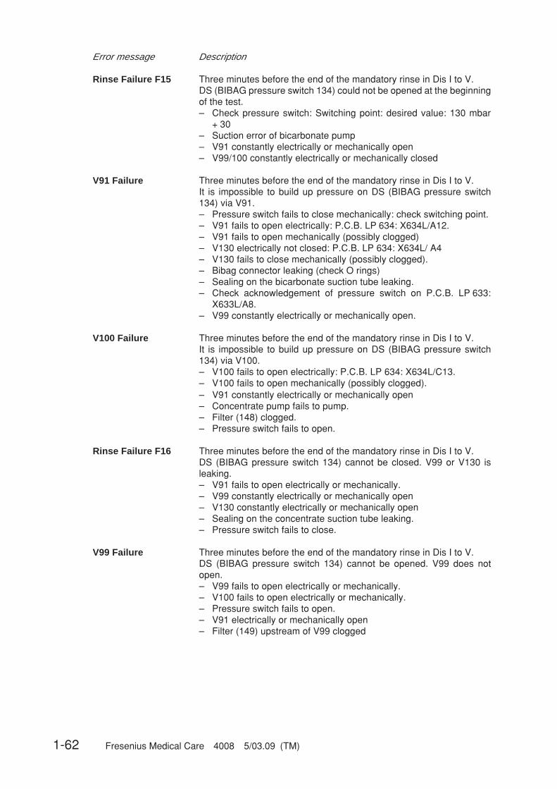
1-62 Fresenius Medical Care 4008 5/03.09 (TM)
Error message Description
Rinse Failure F15 Three minutes before the end of the mandatory rinse in Dis I to V.DS (BIBAG pressure switch 134) could not be opened at the beginningof the test.– Check pressure switch: Switching point: desired value: 130 mbar
+ 30– Suction error of bicarbonate pump– V91 constantly electrically or mechanically open– V99/100 constantly electrically or mechanically closed
V91 Failure Three minutes before the end of the mandatory rinse in Dis I to V.It is impossible to build up pressure on DS (BIBAG pressure switch134) via V91.– Pressure switch fails to close mechanically: check switching point.– V91 fails to open electrically: P.C.B. LP 634: X634L/A12.– V91 fails to open mechanically (possibly clogged)– V130 electrically not closed: P.C.B. LP 634: X634L/ A4– V130 fails to close mechanically (possibly clogged).– Bibag connector leaking (check O rings)– Sealing on the bicarbonate suction tube leaking.– Check acknowledgement of pressure switch on P.C.B. LP 633:
X633L/A8.– V99 constantly electrically or mechanically open.
V100 Failure Three minutes before the end of the mandatory rinse in Dis I to V.It is impossible to build up pressure on DS (BIBAG pressure switch134) via V100.– V100 fails to open electrically: P.C.B. LP 634: X634L/C13.– V100 fails to open mechanically (possibly clogged).– V91 constantly electrically or mechanically open– Concentrate pump fails to pump.– Filter (148) clogged.– Pressure switch fails to open.
Rinse Failure F16 Three minutes before the end of the mandatory rinse in Dis I to V.DS (BIBAG pressure switch 134) cannot be closed. V99 or V130 isleaking.– V91 fails to open electrically or mechanically.– V99 constantly electrically or mechanically open– V130 constantly electrically or mechanically open– Sealing on the concentrate suction tube leaking.– Pressure switch fails to close.
V99 Failure Three minutes before the end of the mandatory rinse in Dis I to V.DS (BIBAG pressure switch 134) cannot be opened. V99 does notopen.– V99 fails to open electrically or mechanically.– V100 fails to open electrically or mechanically.– Pressure switch fails to open.– V91 electrically or mechanically open– Filter (149) upstream of V99 clogged
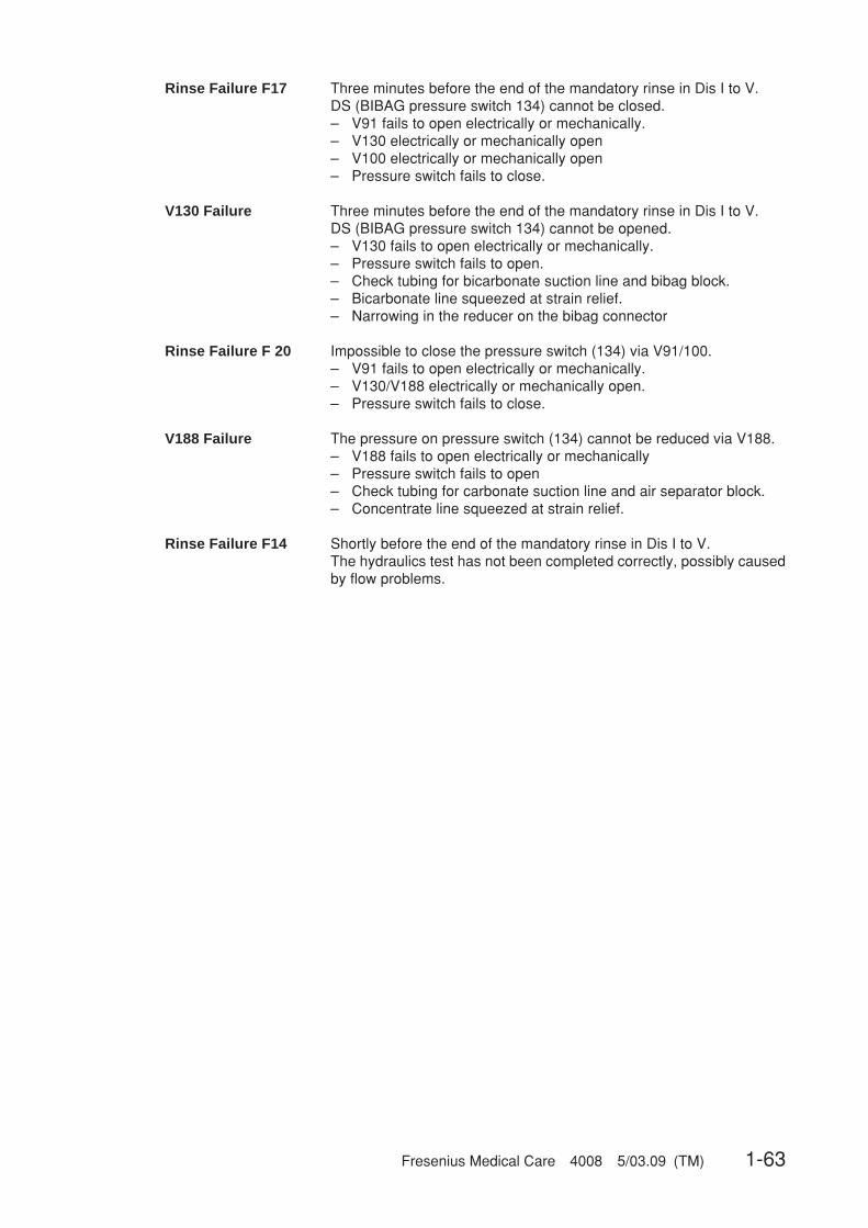
Fresenius Medical Care 4008 5/03.09 (TM) 1-63
Rinse Failure F17 Three minutes before the end of the mandatory rinse in Dis I to V.DS (BIBAG pressure switch 134) cannot be closed.– V91 fails to open electrically or mechanically.– V130 electrically or mechanically open– V100 electrically or mechanically open– Pressure switch fails to close.
V130 Failure Three minutes before the end of the mandatory rinse in Dis I to V.DS (BIBAG pressure switch 134) cannot be opened.– V130 fails to open electrically or mechanically.– Pressure switch fails to open.– Check tubing for bicarbonate suction line and bibag block.– Bicarbonate line squeezed at strain relief.– Narrowing in the reducer on the bibag connector
Rinse Failure F 20 Impossible to close the pressure switch (134) via V91/100.– V91 fails to open electrically or mechanically.– V130/V188 electrically or mechanically open.– Pressure switch fails to close.
V188 Failure The pressure on pressure switch (134) cannot be reduced via V188.– V188 fails to open electrically or mechanically– Pressure switch fails to open– Check tubing for carbonate suction line and air separator block.– Concentrate line squeezed at strain relief.
Rinse Failure F14 Shortly before the end of the mandatory rinse in Dis I to V.The hydraulics test has not been completed correctly, possibly causedby flow problems.

1-64 Fresenius Medical Care 4008 5/03.09 (TM)
● V39 test
The following requirements must be fulfilled to run the V39 test:
1. The test is run during the last minute of the mandatory rinse program only.2. DIP switch 5 DIP array 2 on PCB LP 632 must be set to OFF.
Man
dato
ry r
inse
≤ 1
min
DA
C d
egas
. pum
p =
200
open
: V26
, V91
, V99
, V10
0,
V31
, V33
, V35
, V37
;V
39 c
lose
d
Wai
t for
10
sec.
Mea
sure
for
5 se
c.:
Mea
n pr
essu
re v
alue
dav
1
Ope
n V
39;
Wai
t for
5 s
ec.
Mea
sure
for
5 se
c.:
Mea
n pr
essu
re v
alue
dav
2
BiB
ag
syst
em?
yes
no
Pre
ssur
e in
crea
se?
(dav
1 +
20 m
mH
g <
dav2
)
yes
no
Test
pas
sed
Del
ete
man
dato
ry r
inse
Pre
ssur
e co
mpe
nsat
ion
Eva
cuat
e rin
se c
ham
bers
Pre
ssur
e in
crea
se?
(dav
1 +
50 m
mH
g <
dav2
)
yes
no
DA
C d
egas
. pum
p=
200
?
no
yes
Test
faile
dP
ress
ure
com
pens
atio
n“V
39 F
ailu
re”
DA
C d
eg. p
ump
= 2
20

Fresenius Medical Care 4008 5/03.09 (TM) 1-65
Error message Description
V39 Failure On opening V39 a difference in pressure (averaged value V39 open –averaged value V39 closed) is detected on the dialysate pressuretransducer (182):Standard system: < 50 mmHgbibag system: < 20 mmHg– V39 fails to open / close electrically or mechanically (possibly
hydraulic processing unit defective).– It is impossible to re-adjust the degassing pump (P.C.B. LP 634).– V91, V99, V100 fail to open electrically or mechanically.– Dialysate pressure transducer (182) defective or not calibrated
(possibly HPU P.C.B. LP 941 defective)– Filter 210 (upstream of degassing pump) clogged.

1-66 Fresenius Medical Care 4008 5/03.09 (TM)
● Further messages which may be displayed before or during a cleaning program
Error message Description
Blood Sensed by OD Start of a cleaning program in RI I to II, HR I to III, Dis I to V.The optical detector in the air detector module recognizes blood.
Shunt Cover open Start of a cleaning program or during a cleaning programin RI I to II, HR I to III, Dis I to V.The shunt interlock is not closed.
Dialines not conn Start of a cleaning programin RI I to II, HR I to III, Dis I to V.The dialysate couplings are not connected to the shunt interlock.
No LD alarm Priming of the blood line systemin RI I to II, HR I to III, Dis I to V.The drip chamber in the air detector module does not recognize anyalarm.
Conc line not conn Start of a cleaning programin RI I to II, HR I to III, Dis I to V,or end of the disinfectant suction phase in Dis V.The concentrate plug is not connected to the rinse chamber.Reconnect the concentrate plug to the rinse chamber.
Bic line not conn Start of a cleaning programin RI I to II, HR I to III, Dis I to V,or end of the disinfectant suction phase in Dis V.The bicarbonate plug is not connected to the rinse chamber.Reconnect the bicarbonate plug to the rinse chamber.
Voltage Failure During a cleaning programin RI I to II, HR I to III, Dis I to V.The 24-V/12-V supply voltages are drifting.This error can be acknowledged for 8 sec by pressing the respectiveprogram key.
CPU-II failed During a cleaning programin RI I to II, HR I to III, Dis I to V.The watchdog relay has dropped.Communication (RxD or TxD) may be disturbed.
High temperature During a cleaning programin RI I to II, HR I to III, Dis I to V.Temperature > 41 °C; > 90 °C during HR; > 91 °C during IHR.The system continues to run.The alarm tone can be acknowledged.Upon error elimination, the message is automatically cleared.
Low temperature During a cleaning programin RI I to II, HR I to III, Dis I to V.Temperature < 33 °C; < 78.5 °C during HR.The system continues to run.The alarm tone can be acknowledged.Upon error elimination, the message is automatically cleared.
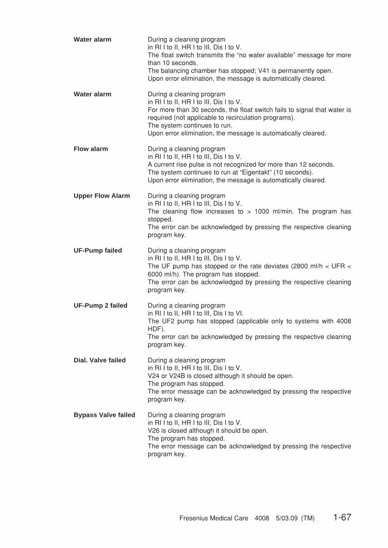
Fresenius Medical Care 4008 5/03.09 (TM) 1-67
Water alarm During a cleaning programin RI I to II, HR I to III, Dis I to V.The float switch transmits the “no water available” message for morethan 10 seconds.The balancing chamber has stopped; V41 is permanently open.Upon error elimination, the message is automatically cleared.
Water alarm During a cleaning programin RI I to II, HR I to III, Dis I to V.For more than 30 seconds, the float switch fails to signal that water isrequired (not applicable to recirculation programs).The system continues to run.Upon error elimination, the message is automatically cleared.
Flow alarm During a cleaning programin RI I to II, HR I to III, Dis I to V.A current rise pulse is not recognized for more than 12 seconds.The system continues to run at “Eigentakt” (10 seconds).Upon error elimination, the message is automatically cleared.
Upper Flow Alarm During a cleaning programin RI I to II, HR I to III, Dis I to V.The cleaning flow increases to > 1000 ml/min. The program hasstopped.The error can be acknowledged by pressing the respective cleaningprogram key.
UF-Pump failed During a cleaning programin RI I to II, HR I to III, Dis I to V.The UF pump has stopped or the rate deviates (2800 ml/h < UFR <6000 ml/h). The program has stopped.The error can be acknowledged by pressing the respective cleaningprogram key.
UF-Pump 2 failed During a cleaning programin RI I to II, HR I to III, Dis I to VI.The UF2 pump has stopped (applicable only to systems with 4008HDF).The error can be acknowledged by pressing the respective cleaningprogram key.
Dial. Valve failed During a cleaning programin RI I to II, HR I to III, Dis I to V.V24 or V24B is closed although it should be open.The program has stopped.The error message can be acknowledged by pressing the respectiveprogram key.
Bypass Valve failed During a cleaning programin RI I to II, HR I to III, Dis I to V.V26 is closed although it should be open.The program has stopped.The error message can be acknowledged by pressing the respectiveprogram key.

1-68 Fresenius Medical Care 4008 5/03.09 (TM)
V102 Failure During a cleaning programin RI I to II, HR I to III, Dis I to V.V102 has been opened electrically.24 V are switched off.The error cannot be acknowledged.
V104 Failure During a cleaning programin RI I to II, HR I to III, Dis I to V.V104 has been opened electrically.24 V are switched off.The error cannot be acknowledged.
HDF-Pump failure During a cleaning programin RI I to II, HR I to III, Dis I to V.The HDF pump has stopped, or the speed deviates (rated value:400 ml/min, actual value: ≤ 300 ml/min; rated value: 150 ml/min, actualvalue: ≤ 100 ml/min).The error message can be acknowledged for one complete cleaningprogram run by pressing the respective program key. The prompt:“Are you sure ?” is displayed.
Float-Switch Failure During a disinfectant program in the suction phase in Dis I to V (CDS:Dis I to IV).The lower switching point of the float switch is not reached within20 sec.The program has stopped.
Connect Disinfectant Disinfectant suction phase in Dis V.Request to connect the disinfectant.
Press CONFIRM key Disinfectant suction phase in Dis V.After the disinfectant has been connected, the Confirm key on themenu panel must be pressed to start the suction procedure.The program has stopped.
Please Wait Disinfectant suction phase in Dis V.Disinfectant is drawn in via the concentrate pump.
Disinfectant empty ? Disinfectant suction phase in Dis I to V.Dis V: After the disinfectant has been drawn in, the float switch does notrecognize any fluid.Dis I to IV, Dis VI: The V84 monitoring unit does not recognize anyconductivity.
Disinf-Temp. too high Transition to disinfection in Dis I to V.Temperature at the end of the rinse-free procedure > 40 °C.Again and again, the rinse-free procedure is prolonged by 1 minute.An audible warning is sounded after 4 minutes.The message is automatically cleared, and it cannot be acknowledged.

Fresenius Medical Care 4008 5/03.09 (TM) 1-69
Rinse required ! During stored mandatory rinse in Dis I to V.The mandatory rinse has been interrupted (e.g. the system has beenswitched off).
Rinse after Disinf. Selection of a cleaning program, although a mandatory rinse has beenrequested in HR.A disinfection program has been stopped and subsequently a rinsing orhot rinsing program started.
Power Failure During a cleaning programin RI I to II, HR I to III, Dis I to V.Line voltage failed.
BIBAG connect. open Upon start of a cleaning programin RI I to II, HR I to III, Dis I to V.The BIBAG connector is not closed (cap not attached).
Heater error During the CDS rinsing phase at the end of a hot rinsing program or ahot disinfection program in CDS: HR I to III, Dis II to IV.The heater signal (P.C.B. LP 633: X633R/A26) is not changing for > 40sec.
Accumulator empty! Battery voltage <17.2 V ±2.5 %Only in the event of a power failure during the cleaning programs.If the voltage drops below 17 V, the system will switch off.

1-70 Fresenius Medical Care 4008 5/03.09 (TM)
1.1.5 Error messages after turning power on
Error message Description
EPROM ERROR System error.Check the plugs and the EPROM for proper connection. Replace theEPROM, if necessary.
BRAM_#_XXXX_XXXX_XXXXSystem error.Switch the system off and on again.Check the plugs and the BRAM of P.C.B. LP 631 and P.C.B. LP 632 forproper connection. Replace the BRAM, if necessary.Then recalibrate.
RAM ERROR System error.Switch the system off and on again.Check the plugs and the RAM for proper connection. Replace theRAM, if necessary.
Keyboard Error Short-circuit on the keyboard.Switch the system off and on again.Check the plugs for proper connection. Possible short-circuit on thekeys. Replace the front panel, if necessary.
Watchdog Error This error message can only be displayed shortly after switch-on.Switch the system off and on again.Check the WD relay and components. Check CPU2/CPU1. Check theplug connectors on the monitor.
XX (not calibrated) NOVRAM error upon test request.Switch the system off and on again.Recalibrate the function indicated. Replace the NOVRAM, if neces-sary.
NTC109 switched off No valid value has been filed during start in the NOVRAM. The differ-ence in temperature between NTC 109 and NTC 3 is too large.Switch off NTC 109 in the setup menu, or recalibrate the temperature.

Fresenius Medical Care 4008 5/03.09 (TM) 1-71
1.1.6 Error messages during dialysis
Error message Description
Voltage Failure The 24-V/12-V supply voltages are drifting.The system enters the safe state and must be switched off/on.– The 12-V or 24-V operating voltage is outside of the permissible
range:24 V: > 26 V / < 22.5 V12 V: > 13.5 to 15 V / < 10.5 V
– Check the power supply unit.– Power supply unit okay: Check the voltages applied to P.C.B.
LP 633:+12 V: X633R/A, C31+24 V: 24V_EM: X633L/B20
24 V Switched Off The 24-V supply voltage has fallen below 5 V.The system enters the safe state and must be switched off/on.– Check the power supply unit.– Power supply unit okay: Check the voltages at P.C.B. LP 633:
+24V_EM: X633L/B20– Remove all plug-in modules. As soon as the system is running:
reconnect each plug-in module individually with the systemswitched off; determine the defective module and repair it.
– Completely loosen the hydraulic compartment connections.Caution: J1 must now be fitted on P.C.B. LP 630 since, without it,the system would not be able to perform the watchdog test. Beabsolutely sure to remove the jumper again for hemodialysis opera-tion.With the system running, check the short circuit in the hydrauliccompartment for 24-V supply and the valves and pumps for shortcircuit.
CPU-II failed CPU2 fails to communicate via the serial interface.The system enters the safe state and must be switched off/on.– The software versions of CPU1 and CPU2 are mismatching.– Hardware defect on CPU2.
Profile time diff. Deviation in time between CPU1 and CPU2.The error message is emitted 60 seconds after the start of the profile.– The clock module on CPU1 (IC14) is defective; or calibrate the time
in case of layout < D.
Cyclical PHT F01 Balancing error.– System leakage.– Applicable to Diasafe systems: On CPU II, the DIP switch array 2,
switch 1, is not set to “ON”.
Cyclical PHT F02 Balancing error.– System leakage.– Applicable to Diasafe systems: On CPU II, the DIP switch array 2,
switch 1, is not set to “ON”.
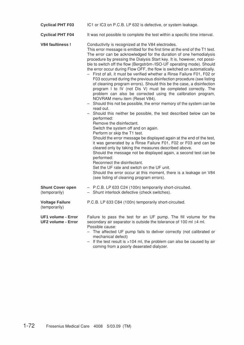
1-72 Fresenius Medical Care 4008 5/03.09 (TM)
Cyclical PHT F03 IC1 or IC3 on P.C.B. LP 632 is defective, or system leakage.
Cyclical PHT F04 It was not possible to complete the test within a specific time interval.
V84 faultiness ! Conductivity is recognized at the V84 electrodes.This error message is emitted for the first time at the end of the T1 test.The error can be acknowledged for the duration of one hemodialysisprocedure by pressing the Dialysis Start key. It is, however, not possi-ble to switch off the flow (Bergström-/ISO-UF operating mode). Shouldthe error occur during Flow OFF, the flow is switched on automatically.– First of all, it must be verified whether a Rinse Failure F01, F02 or
F03 occurred during the previous disinfection procedure (see listingof cleaning program errors). Should this be the case, a disinfectionprogram I to IV (not Dis V) must be completed correctly. Theproblem can also be corrected using the calibration program,NOVRAM menu item (Reset V84).
– Should this not be possible, the error memory of the system can beread out.
– Should this neither be possible, the test described below can beperformed:Remove the disinfectant.Switch the system off and on again.Perform or skip the T1 test.Should the error message be displayed again at the end of the test,it was generated by a Rinse Failure F01, F02 or F03 and can becleared only by taking the measures described above.Should the message not be displayed again, a second test can beperformed:Reconnect the disinfectant.Set the UF rate and switch on the UF unit.Should the error occur at this moment, there is a leakage on V84(see listing of cleaning program errors).
Shunt Cover open – P.C.B. LP 633 C24 (100n) temporarily short-circuited.(temporarily) – Shunt interlock defective (check switches).
Voltage Failure P.C.B. LP 633 C84 (100n) temporarily short-circuited.(temporarily)
UF1 volume - Error Failure to pass the test for an UF pump. The fill volume for theUF2 volume - Error secondary air separator is outside the tolerance of 100 ml ±4 ml.
Possible cause:– The affected UF pump fails to deliver correctly (not calibrated or
mechanical defect)– If the test result is >104 ml, the problem can also be caused by air
coming from a poorly deaerated dialyzer.

Fresenius Medical Care 4008 5/03.09 (TM) 1-73
F327 UF-failure Pause between two UF1 pump strokes less than 220 ms.Possible cause:– CPU-1 defective
F328 UF-failure Pulse time of one UF1 pump stroke less than 180 ms.Possible cause:– Controlling monoflop on LP 634 defective
F329 UF-failure Pulse time of one UF1 pump stroke exceeds 500 msPossible cause:– Controlling monoflop on LP 634 defective.
F330 UF-failure Pick-up time of the UF1 pump exceeds 10 sec.Possible cause:– Controlling output stage on LP 634 defective.
F331 UF-failure Theoretical/actual rate of the UF1 pump deviates by more than ±10 %.Possible cause:– System error
F332 UF-failure UF1 pump stopped for more than the maximum time period.Possible cause:– Controlling output stage on LP 634 defective.– UF pump interruption– System error
F333 UF-failure Volume changes by more than 10 ml during prescribed standstill (onlymonitored if OD is dark).Possible cause:– System error
F334 UF-failure Pause between two UF2 pump strokes less than 220 ms.Possible cause:– CPU-1 defective
F335 UF-failure Pulse time of one UF2 pump stroke less than 180 ms.Possible cause:– Controlling monoflop on LP 634 defective.
F336 UF-failure Pulse time of one UF2 pump stroke exceeds 500 ms.Possible cause:– Controlling monoflop on LP 634 defective.
F337 UF-failure Starting time of the UF2 pump exceeds 10 sec.Possible cause:– Controlling output stage on LP 634 defective.
F338 UF-failure Desired/actual rate of the UF2 pump deviates by more than 10 %.Possible cause:– System error
F339 UF-failure UF2 pump stopped for more than the maximum time period.Possible cause:– Controlling output stage on LP 634 defective.– UF pump interruption– System error
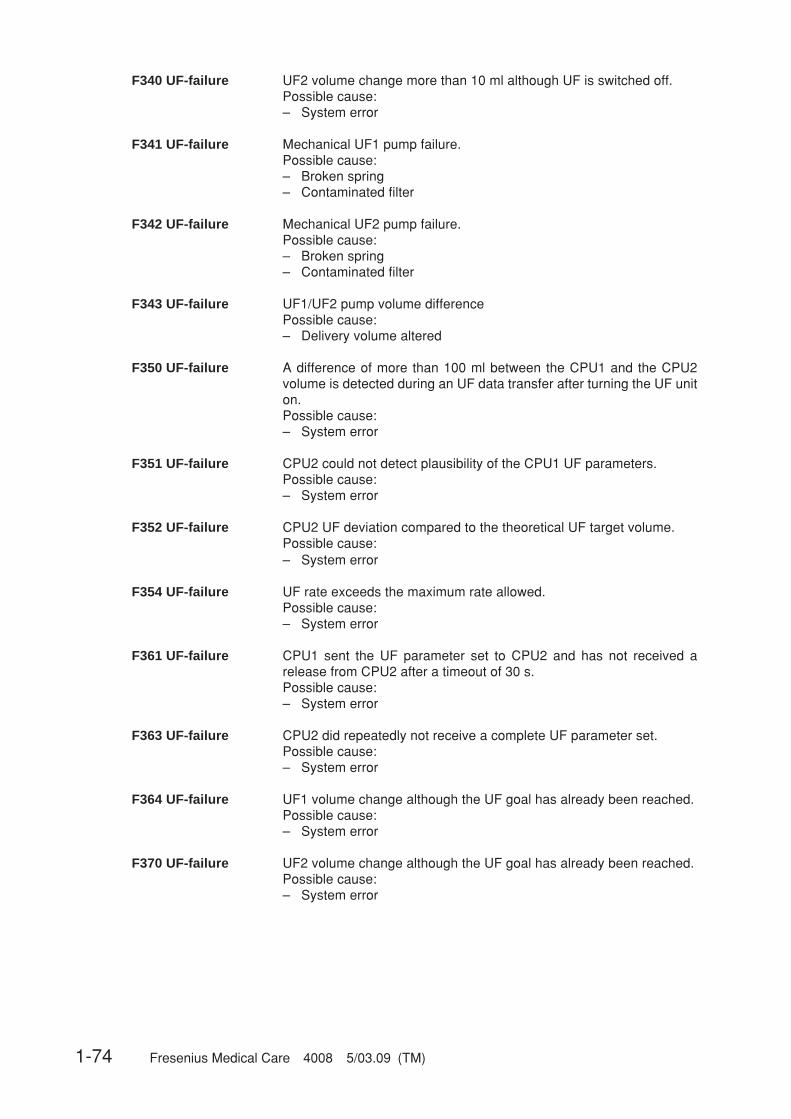
1-74 Fresenius Medical Care 4008 5/03.09 (TM)
F340 UF-failure UF2 volume change more than 10 ml although UF is switched off.Possible cause:– System error
F341 UF-failure Mechanical UF1 pump failure.Possible cause:– Broken spring– Contaminated filter
F342 UF-failure Mechanical UF2 pump failure.Possible cause:– Broken spring– Contaminated filter
F343 UF-failure UF1/UF2 pump volume differencePossible cause:– Delivery volume altered
F350 UF-failure A difference of more than 100 ml between the CPU1 and the CPU2volume is detected during an UF data transfer after turning the UF uniton.Possible cause:– System error
F351 UF-failure CPU2 could not detect plausibility of the CPU1 UF parameters.Possible cause:– System error
F352 UF-failure CPU2 UF deviation compared to the theoretical UF target volume.Possible cause:– System error
F354 UF-failure UF rate exceeds the maximum rate allowed.Possible cause:– System error
F361 UF-failure CPU1 sent the UF parameter set to CPU2 and has not received arelease from CPU2 after a timeout of 30 s.Possible cause:– System error
F363 UF-failure CPU2 did repeatedly not receive a complete UF parameter set.Possible cause:– System error
F364 UF-failure UF1 volume change although the UF goal has already been reached.Possible cause:– System error
F370 UF-failure UF2 volume change although the UF goal has already been reached.Possible cause:– System error
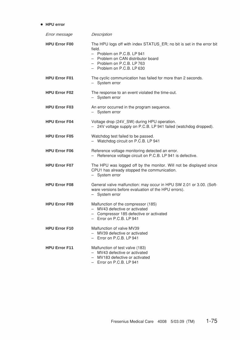
Fresenius Medical Care 4008 5/03.09 (TM) 1-75
● HPU error
Error message Description
HPU Error F00 The HPU logs off with index STATUS_ER; no bit is set in the error bitfield.– Problem on P.C.B. LP 941– Problem on CAN distributor board– Problem on P.C.B. LP 763– Problem on P.C.B. LP 630
HPU Error F01 The cyclic communication has failed for more than 2 seconds.– System error
HPU Error F02 The response to an event violated the time-out.– System error
HPU Error F03 An error occurred in the program sequence.– System error
HPU Error F04 Voltage drop (24V_SW) during HPU operation.– 24V voltage supply on P.C.B. LP 941 failed (watchdog dropped).
HPU Error F05 Watchdog test failed to be passed.– Watchdog circuit on P.C.B. LP 941
HPU Error F06 Reference voltage monitoring detected an error.– Reference voltage circuit on P.C.B. LP 941 is defective.
HPU Error F07 The HPU was logged off by the monitor. Will not be displayed sinceCPU1 has already stopped the communication.– System error
HPU Error F08 General valve malfunction: may occur in HPU SW 2.01 or 3.00. (Soft-ware versions before evaluation of the HPU errors).– System error
HPU Error F09 Malfunction of the compressor (185)– MV43 defective or activated– Compressor 185 defective or activated– Error on P.C.B. LP 941
HPU Error F10 Malfunction of valve MV39– MV39 defective or activated– Error on P.C.B. LP 941
HPU Error F11 Malfunction of test valve (183)– MV43 defective or activated– MV183 defective or activated– Error on P.C.B. LP 941

1-76 Fresenius Medical Care 4008 5/03.09 (TM)
HPU Error F12 Malfunction of evacuation valve (188)– MV188 defective or activated– Error on P.C.B. LP 941
HPU Error F13 Malfunction of retentate valve (189)– MV189 defective or activated– Error on P.C.B. LP 941
HPU Error F14 Defective component on P.C.B. LP 941– Error on P.C.B. LP 941
HPU Error F15 Error in the HPU software. Valves are activated incorrectly.– System error
HPU Error F98 Proceeding to the T1 test is not allowed after restart.– System error
HPU Error F99 HPU fails without logging off.– Damaged cable or similar problem– HPU logged off by CPU1– CRC error in the transfer HPU → CPU1– BVM is connected via CAN and software <3.20 is installed in the
BVM.– The VDE test was performed directly after turning the system on.
Turn the system on at least 2 minutes before the test.

Fresenius Medical Care 4008 5/03.09 (TM) 1-77
● ONLINE module errors
Error message Description
ONL Error F00 Online module error
ONL Error F01 Watchdog error
ONL Error F02 Watchdog error
ONL Error F03 Watchdog error
ONL Error F04 Error in the program sequence
ONL Error F05 +24V_WD dropped to less than 17V or was switched off
ONL Error F06 Time-out of the communication watchdog exceeded
ONL Error F07 A transmission from the module was not confirmed by the dialysissystem
ONL Error F08 General valve error
ONL Error F09 T1 test skipped
ONL Error F10 T1 test for ONLINEplus failed to be passed
ONL Error F11 Reference voltage is outside the tolerance
ONL Error F12 CRC error
ONL Error F13 EEPROM error
ONL Error F14 The monitor disabled the ONLINEplus module
ONL Error F16 Valve error ONL1
ONL Error F17 Valve error ONL2
ONL Error F18 Valve error ONL3

1-78 Fresenius Medical Care 4008 5/03.09 (TM)
1.2 Functional description of the modules
1.2.1 Blood pump (arterial)
The blood pump ensures a sufficient blood flow in the extracorporeal blood circuit. It is absolutelynecessary that sterility is maintained and that the blood is prevented from becoming contaminat-ed.
The blood pump is designed as roller pump provided in an exchangeable plug-in moduleintegrated in the hemodialysis system. The blood line is installed between a stator, which, with itsrolling surface bent in a circle, represents a thrust bearing, and a rotor, which is provided withrollers and pivoted in the stator. The pressure of the rollers causes the development of a narrowor seal. If the rollers are moving in the direction of delivery, the blood is pushed in this direction.
A microprocessor controls the stepper motor with quartz accuracy, depending on the selecteddelivery rate, the set line diameter, and the monitor signals.
The pressure measuring equipment comprises a piezo-resistive pressure transducer. The pres-sure-proportional voltage is indicated on the monitor on a quasi-analog LED scale.
Functions of the blood pump:– RAM and CRC test after turning power on,– control and monitoring of the function by a dual processor system,– emergency switchoff in case of an alarm: stop recognition (15 or 30 sec),– setting of the speed to 180 ml/min during priming,– measurement of the arterial pressure or the Single-Needle pressure (depending on the model
concerned),– semi-automatic loading and unloading of the line segment.
Error messages:E.01 Line diameter outside the permissible rangeE.02 Undefined hex switch positionE.03 Uncalibrated arterial pressure transducerE.04 Run-time monitoring error during SN operationE.05 SN stroke volume outside the permissible rangeE.06 SN pressure thresholds outside the range of values of the A-D converterE.08 Stop alarmE.09 Error during A-D conversionE.12 Rotary monitoring error (Hall sensor)E.13 Monitoring error with regard to current sensing resistorsE.14 Monitoring error with regard to current sensing resistorsE.15 Speed monitoring error
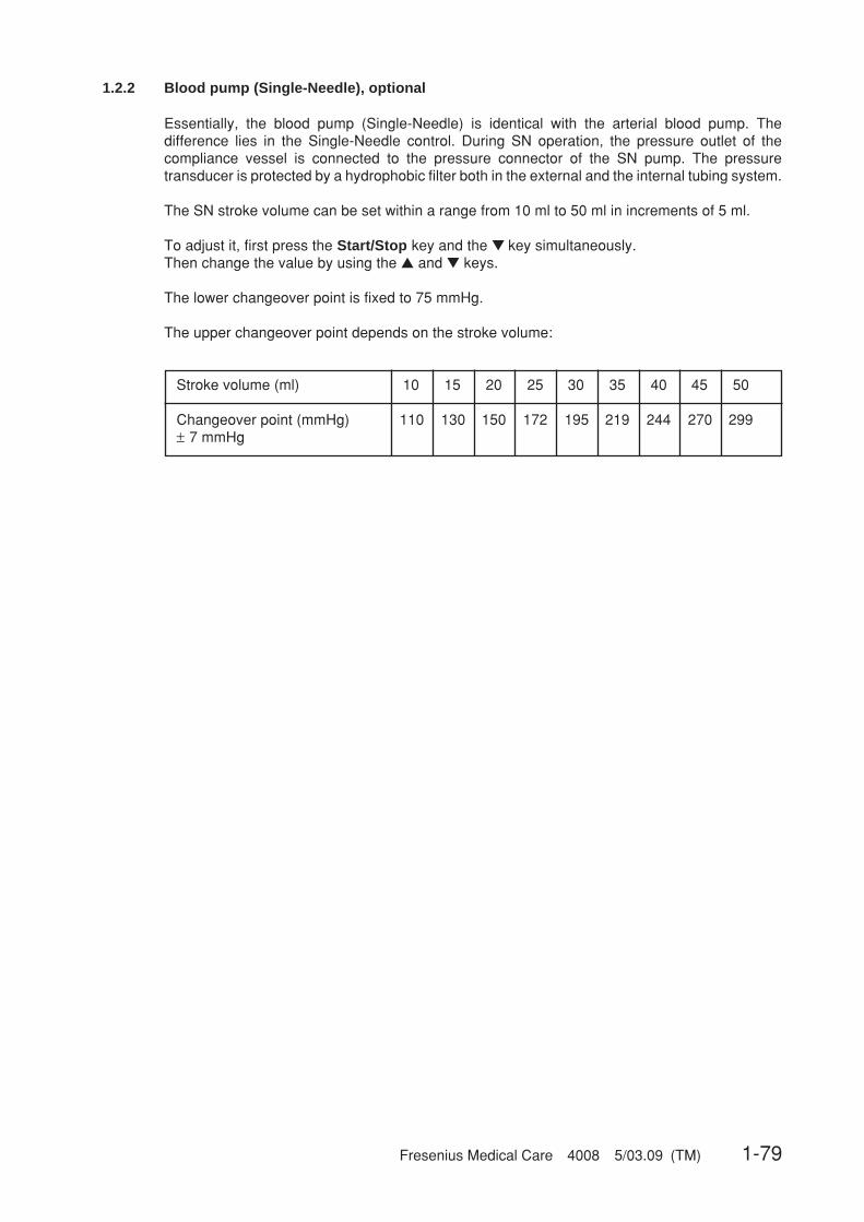
Fresenius Medical Care 4008 5/03.09 (TM) 1-79
1.2.2 Blood pump (Single-Needle), optional
Essentially, the blood pump (Single-Needle) is identical with the arterial blood pump. Thedifference lies in the Single-Needle control. During SN operation, the pressure outlet of thecompliance vessel is connected to the pressure connector of the SN pump. The pressuretransducer is protected by a hydrophobic filter both in the external and the internal tubing system.
The SN stroke volume can be set within a range from 10 ml to 50 ml in increments of 5 ml.
To adjust it, first press the Start/Stop key and the ▼ key simultaneously.Then change the value by using the ▲ and ▼ keys.
The lower changeover point is fixed to 75 mmHg.
The upper changeover point depends on the stroke volume:
Stroke volume (ml) 10 15 20 25 30 35 40 45 50
Changeover point (mmHg) 110 130 150 172 195 219 244 270 299± 7 mmHg
1-80 Fresenius Medical Care 4008 5/03.09 (TM)
1.2.3 Heparin pump
Since the blood flows through an extracorporeal circuit during hemodialysis, coagulation wouldoccur within a short time. The heparin pump allows continuous heparinization of the bloodcausing the coagulation time to be prolonged. Since the heparin volume required during hemodi-alysis depends on the respective patient concerned, it must be determined by the attendingphysician.
A syringe plunger is moved by a drive rod, which is connected to a threaded spindle via a slidingblock. A microprocessor-controlled stepper motor causes the spindle to rotate. Depending on thetype of activation, the plunger moves up or down. A Hall sensor indicates the upper end positionof the plunger. The protective system of the pump comprises a speed monitoring unit (slotted discwith optical sensor) as well as a motor current monitoring unit.
The different syringe types can be selected by means of a coding switch:0 20 ml B&D syringe1 30 ml Fresenius syringe2 50 ml Fresenius syringe3 10 ml B&D syringe4 30 ml B&D syringe5 50 ml B&D syringe6 20 ml Terumo syringe7 30 ml Terumo syringe8 50 ml Terumo syringe9 20 ml JMS syringeA 20 ml Nipro syringeB – F not used
CautionDo not change the coding switch position during operation.
Function of the heparin pump:– RAM and CRC test after turning power on,– delivery rate adjustable from 0.1 ml to 10 ml in increments of 0.1 ml,– delivery time preselection (stopwatch) adjustable from 1 min to 9 h 59 min,– bolus administration.
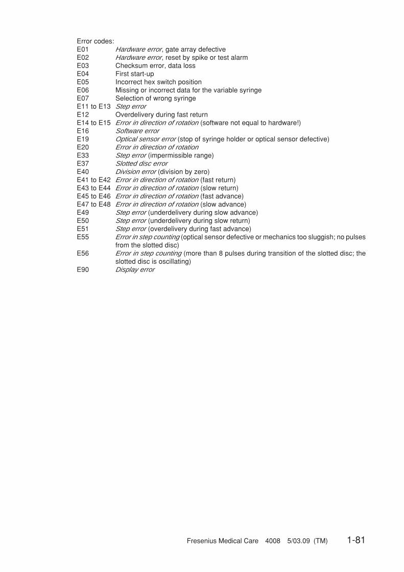
Fresenius Medical Care 4008 5/03.09 (TM) 1-81
Error codes:E01 Hardware error, gate array defectiveE02 Hardware error, reset by spike or test alarmE03 Checksum error, data lossE04 First start-upE05 Incorrect hex switch positionE06 Missing or incorrect data for the variable syringeE07 Selection of wrong syringeE11 to E13 Step errorE12 Overdelivery during fast returnE14 to E15 Error in direction of rotation (software not equal to hardware!)E16 Software errorE19 Optical sensor error (stop of syringe holder or optical sensor defective)E20 Error in direction of rotationE33 Step error (impermissible range)E37 Slotted disc errorE40 Division error (division by zero)E41 to E42 Error in direction of rotation (fast return)E43 to E44 Error in direction of rotation (slow return)E45 to E46 Error in direction of rotation (fast advance)E47 to E48 Error in direction of rotation (slow advance)E49 Step error (underdelivery during slow advance)E50 Step error (underdelivery during slow return)E51 Step error (overdelivery during fast advance)E55 Error in step counting (optical sensor defective or mechanics too sluggish; no pulses
from the slotted disc)E56 Error in step counting (more than 8 pulses during transition of the slotted disc; the
slotted disc is oscillating)E90 Display error

1-82 Fresenius Medical Care 4008 5/03.09 (TM)
1.2.4 Air detector
The penetration of air into the patient's extracorporeal blood circuit may cause an air embolism.In order to catch limited amounts of air and to separate accompanying air bubbles, the venousblood line is expanded (venous drip chamber). A major task of the air detector is to monitor thefilling level in the venous drip chamber.
Ultrasonic air detector
The protection system against air infusion uses the method of ultrasonic transmission. Ultrasonicconverters are attached on either side of the venous bubble catcher. At periodic intervals ofapprox. 90 ms, a transmitting resonator generates attenuated ultrasonic vibrations at a naturalresonance of approx. 90 kHz, which are absorbed by a receiving resonator. The amplitude of thesignal received is dependent upon the medium between the converters. Its value is at itsminimum with the bubble catcher empty (air) and at its maximum with bubble-free fluids. Theamplitude decreases with increasing air content (foam). The signal path is fail-safe up to andincluding the receiving resonator, i.e. the failure of any component always leads to a smalleramplitude and, thus, to an alarm. Starting at the receiving resonator, the signal voltage is alwayssent onto two independent receiver paths. As soon as the signal is too weak, one of thesereceiver paths causes the blood pump to stop and the other the venous line clamp to close.
The ▲ and ▼ keys are used to both raise and lower the blood level in the venous bubble catcher.As long as the ▲ key is pressed, the venous line clamp closes. The vent valve in the air detectormodule opens, and the blood level rises. The blood pump runs at reduced speed (180 ml/min). Aslong as the ▼ key is pressed, the venous line clamp remains open. The vent valve in the airdetector module opens, the ventilation pump is running, and the blood level sinks. The bloodpump runs at the preselected speed.
Optical detector
The optical detector serves to detect if there is blood or saline solution or air in the venous returnline downstream of the bubble catcher. In the hemodialysis system, the hemodialysis phase isdefined by presence of a dark medium and the preparation phase by presence of a clear medium.
Venous pressure measurement
The venous pressure measuring equipment comprises a piezo-resistive pressure sensor provid-ed on the P.C.B. with following operational amplifier. The pressure-proportional output voltage issupplied onto the logic P.C.B. in the monitor. There, the pressure is indicated on a quasi-analogLED scale, and the transmembrane pressure is computed by determinig the difference betweenthe dialysate pressure and the venous pressure.
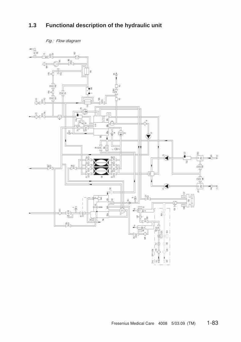
Fresenius Medical Care 4008 5/03.09 (TM) 1-83
1.3 Functional description of the hydraulic unit
Fig.: Flow diagram

1-84 Fresenius Medical Care 4008 5/03.09 (TM)
Legend
2 Temperature sensor3 Temperature sensor4 Temperature sensor (OCM option)5 Float switch6 Level sensor7 Conductivity cell8 Blood leak detector9 Pressure transducer10 Reed contact for concentrate12 Reed contact for bicarbonate21 Flow pump22 UF pump23 Concentrate pump24 Dialyzer valve 124b Dialyzer valve 225 Bicarbonate pump26 Bypass valve29 Degassing pump30 Outlet valve31 Balancing chamber valve 132 Balancing chamber valve 233 Balancing chamber valve 334 Balancing chamber valve 435 Balancing chamber valve 536 Balancing chamber valve 637 Balancing chamber valve 738 Balancing chamber valve 839 Negative pressure valve41 Water inlet valve43 Fill valve54 Heater rod61 Pressure reduction valve63 Filter/water inlet65 Loading pressure valve66 Heater block66a Water inflow chamber66b Heater rod chamber66c Float switch chamber68 Balancing chamber71 Filter/concentrate72 Filter/bicarbonate73 Filter/dialysate74 Filter/UF75 External flow indicator76 Filter/fill valve77 Heat exchanger78 Relief valve84 Disinfection valve85 Disinfection connector86 Recirculation valve87 Drain valve88 Multifunction block88a Degassing chamber88b Secondary air separator88c Primary air separator89 Degassing orifice90a Concentrate rinse chamber90b Bicarbonate rinse chamber91 Rinse valve92 Vent valve94 Concentrate suction tube95 Bicarbonate suction tube
97 Air separating pump98 Rinse valve99 Rinse valve100 Rinse valve102 CDS, concentrate valve104 CDS, bicarbonate valve109 Temperature sensor110 Conductivity cell (OCM option)111 Hydrophobic filter (advanced hydraulics)112 Vent valve (advanced hydraulics)114 Dialysate filter115 Disinfection valve sensor116 Fluid sample valve117 Check valve (concentrate)118 Check valve (bicarbonate)119 Filter (concentrate)120 Filter (bicarbonate)121 CDS, concentrate connector122 CDS, bicarbonate connector123 Pressure switch for V102124 Pressure switch for V104125 Temperature compensation plate130 Bibag drain valve132 Bibag conductivity cell133 Bibag temperature sensor134 Bibag pressure transducer136 Bibag connector137 Bibag microswitch 1138 Bibag microswitch 2148 Filter (rinse valve 100)149 Filter (rinse valve 99)151 Orifice182 Pressure transducer 2 (advanced hydraulics)183 Test valve (advanced hydraulics)184 Hydrophobic filter185 Compressor (advanced hydraulics)188 Evacuation valve189 Retentate valve190 Online filter (Online plus option)191 Online 3 valve (Online plus option)192 Online 2 valve (Online plus option)193 Online 1 valve (Online plus option)194 Rinse port (Online plus option)195 Substituate port (Online plus option)201 Concentrate air separator202 Concentrate level sensor203 Bicarbonate air separator204 Bicarbonate level sensor205 Concentrate / bicarbonate mixing point210 Filter
Hydraulics measuring points
A Reduced water inlet pressureB Loading pressureC Pressure of flow pumpD Pressure of degassing pump
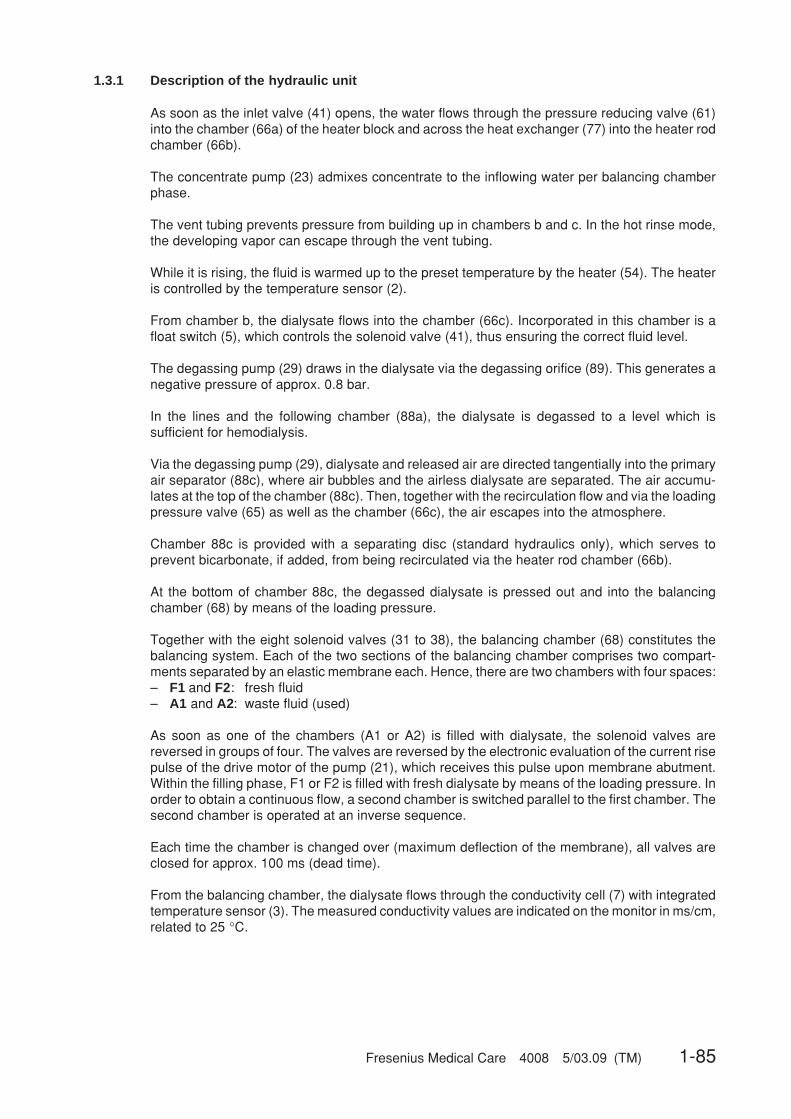
Fresenius Medical Care 4008 5/03.09 (TM) 1-85
1.3.1 Description of the hydraulic unit
As soon as the inlet valve (41) opens, the water flows through the pressure reducing valve (61)into the chamber (66a) of the heater block and across the heat exchanger (77) into the heater rodchamber (66b).
The concentrate pump (23) admixes concentrate to the inflowing water per balancing chamberphase.
The vent tubing prevents pressure from building up in chambers b and c. In the hot rinse mode,the developing vapor can escape through the vent tubing.
While it is rising, the fluid is warmed up to the preset temperature by the heater (54). The heateris controlled by the temperature sensor (2).
From chamber b, the dialysate flows into the chamber (66c). Incorporated in this chamber is afloat switch (5), which controls the solenoid valve (41), thus ensuring the correct fluid level.
The degassing pump (29) draws in the dialysate via the degassing orifice (89). This generates anegative pressure of approx. 0.8 bar.
In the lines and the following chamber (88a), the dialysate is degassed to a level which issufficient for hemodialysis.
Via the degassing pump (29), dialysate and released air are directed tangentially into the primaryair separator (88c), where air bubbles and the airless dialysate are separated. The air accumu-lates at the top of the chamber (88c). Then, together with the recirculation flow and via the loadingpressure valve (65) as well as the chamber (66c), the air escapes into the atmosphere.
Chamber 88c is provided with a separating disc (standard hydraulics only), which serves toprevent bicarbonate, if added, from being recirculated via the heater rod chamber (66b).
At the bottom of chamber 88c, the degassed dialysate is pressed out and into the balancingchamber (68) by means of the loading pressure.
Together with the eight solenoid valves (31 to 38), the balancing chamber (68) constitutes thebalancing system. Each of the two sections of the balancing chamber comprises two compart-ments separated by an elastic membrane each. Hence, there are two chambers with four spaces:– F1 and F2: fresh fluid– A1 and A2: waste fluid (used)
As soon as one of the chambers (A1 or A2) is filled with dialysate, the solenoid valves arereversed in groups of four. The valves are reversed by the electronic evaluation of the current risepulse of the drive motor of the pump (21), which receives this pulse upon membrane abutment.Within the filling phase, F1 or F2 is filled with fresh dialysate by means of the loading pressure. Inorder to obtain a continuous flow, a second chamber is switched parallel to the first chamber. Thesecond chamber is operated at an inverse sequence.
Each time the chamber is changed over (maximum deflection of the membrane), all valves areclosed for approx. 100 ms (dead time).
From the balancing chamber, the dialysate flows through the conductivity cell (7) with integratedtemperature sensor (3). The measured conductivity values are indicated on the monitor in ms/cm,related to 25 °C.

1-86 Fresenius Medical Care 4008 5/03.09 (TM)
The temperature sensor (3) has the following functions:– temperature compensation of the conductivity display,– indication of the dialysate temperature.
Should the actual values (temperature or conductivity) of the dialysate exceed or fall below thelimit settings, the bypass valve (26) opens, and the dialyzer valve (24) is closed. The system isnow in the bypass mode. The dialysate is discharged into the drain not via the dialyzer, but via thesecondary air separator (88b) and the balancing chamber (68).
If the actual conductivity and temperature values of the dialysate are within the set limits, thedialyzer valve (24) opens. The valve (26) is closed. The dialysate flows to the dialyzer.
After the dialyzer, the dialysate which is now loaded with the substances usually eliminated withthe urine flows into the secondary air separator (88b) via a filter (73), the valve (24b) and theblood leak detector (8). The secondary air separator (88b) comprises the pressure transducer (9)and the level sensor (6).
With a hematocrit of 0.25, blood losses of 0.5 ml per minute are recognized in the dialysate by theblood leak detector.
Together with the venous back pressure, the signal of the pressure transducer (9) is evaluatedand indicated on the monitor as TMP. The fluid level in the secondary air separator (88b) ismonitored by the level sensor (6). Due to the secondary air separator (88b), only airless dialysateis always delivered into the balancing chamber (68). Any presence of air bubbles in the balancingchamber (68) would cause balancing errors.
The dialysate is pressed into the balancing chamber (68) by the flow pump (21). As mentionedabove, the balancing chamber valves are reversed by the current rise pulses of the drive motor ofthe flow pump. Using the speed of this pump, the dialysate flow can be adjusted in the dialysisprogram: 300, 500, and 800 ml/min. In the cleaning programs, the flow of the dialysate is fixed.
The relief valve (78) is used to limit the pressure of the flow pump before the balancing chamberto approx. 2 bar.
After the balancing chamber, the dialysate flows through the valve (30), the heat exchanger (77)and the valve (87) into the drain.
The valves (86) and (87) serve to recirculate fluid during the hot rinsing and disinfectionprograms.
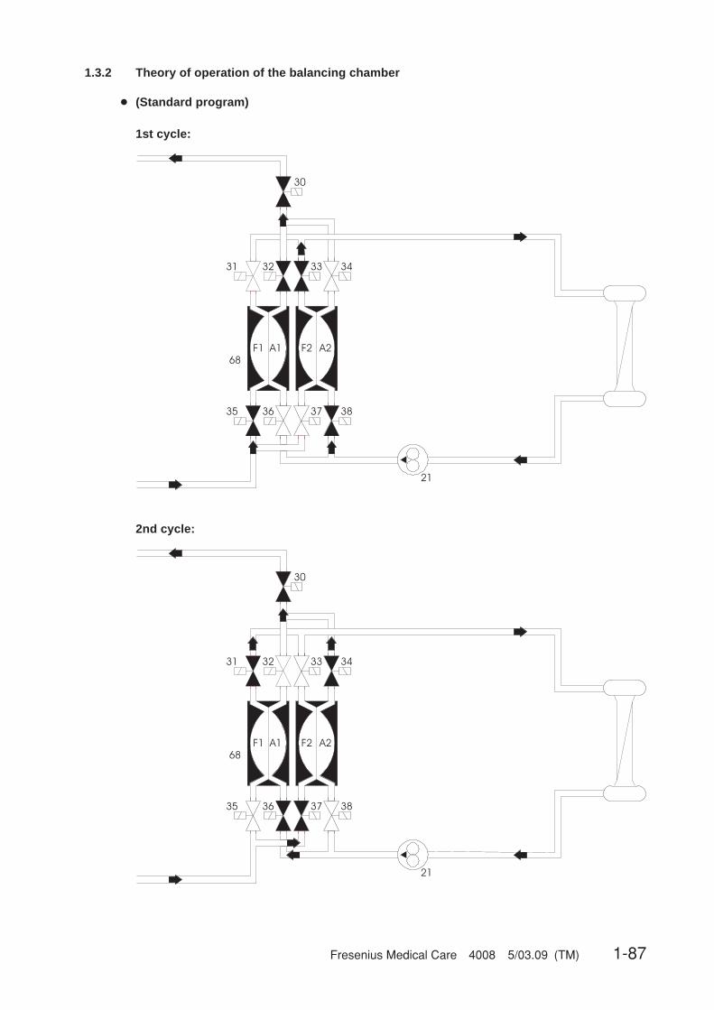
Fresenius Medical Care 4008 5/03.09 (TM) 1-87
1.3.2 Theory of operation of the balancing chamber
● (Standard program)
1st cycle:
2nd cycle:
31 32 33 34
35 36 37 38
21
F2 A2F1 A1
68
30
31 32 33 34
35 36 37 38
21
F2 A2F1 A1
68
30
1-88 Fresenius Medical Care 4008 5/03.09 (TM)
1st cycle: Closed valves: 31, 34, 36, and 37F1 is filled with fresh dialysate.A1 used dialysate is discharged into the drain.F2 fresh dialysate is forced into the dialyzer.A2 is filled with used dialysate.
2nd cycle: Closed valves: 32, 33, 35, and 38F1 fresh solution is forced into the dialyzer.A1 is filled with used dialysate.F2 is filled with fresh dialysate.A2 used dialysate is discharged into the drain.
This system ensures that equal amounts of fluid enter and exit the dialyzer. This leads to an exactbalancing of the dialysate and, in conjunction with the ultrafiltration pump (22), a controlledvolumetric ultrafiltration.
● Secondary air purging by the air separation pump 97
As soon as the fluid level in the secondary air separator (88b) has dropped below the level sensor(6), this sensor activates the air separation pump (97). Should the fluid level not have reached thelevel sensor (6) within a given time period, the FILL PROGRAM is started.
NoteIn order to recognize the fluid level, the level sensor (6) requires fluid with acertain minimum conductivity, which is definitely achieved in all dialysis pro-grams. Separation of air is only required in the dialysis programs. In all otherprograms, the air separation pump (97) and the valve (43) are force-actuated.
☞
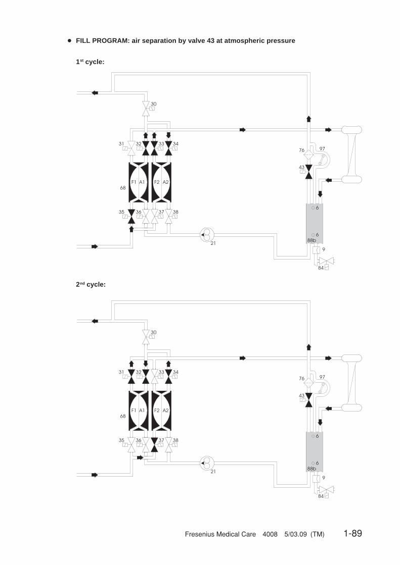
Fresenius Medical Care 4008 5/03.09 (TM) 1-89
● FILL PROGRAM: air separation by valve 43 at atmospheric pressure
1st cycle:
2nd cycle:
97
43
76
6
9
6
88b
84
31 32 33 34
35 36 37 38
21
F2 A2F1 A1
68
30
97
43
76
6
9
6
88b
84
31 32 33 34
35 36 37 38
21
F2 A2F1 A1
68
30

1-90 Fresenius Medical Care 4008 5/03.09 (TM)
If not enough air was separated and the fluid level is still below the level sensor (6), theFILL PROGRAM is activated.
The pump (21) fills either chamber A1 or chamber A2. Valves (36), (38), and (30) are closed. Thevalve (43) opens. The air can escape into the drain.
1st cycle: Chamber F1 is filled. This forces the fluid from chamber A1 into chamber A2. Thefluid is then forced into the seconary air separator (88b) by chamber A2 via thedialyzer.
2nd cycle: Chamber F2 is filled. This forces the fluid from chamber A2 into chamber A1. Thefluid is then forced into the secondary air separator (88b) by chamber A1 via thedialyzer.
Filling is performed in this way to prevent a change in conductivity. As is the case in the standardprogram, here as well one stroke of the concentrate pump is still accomplished per balancingchamber cycle (30 ml).
A fill program is always activated at the beginning of hemodialysis (to fill the dialyzer). Should it beactivated during the hemodialysis procedure (OD dark), this is shown on the display.
NoteRepeated activation of the fill program during treatment indicates a defect(leakages).
☞

Fresenius Medical Care 4008 5/03.09 (TM) 1-91
1.3.3 Central delivery system option
The central delivery system is connected to the connectors 121/122. The concentrate flows intothe rinse chambers via the inlet filters and the valves 102/104. Through the connected concen-trate suction tubes, the concentrate pumps deliver the concentrate to the mixing point.
During hemodialysis, the valves 91/99 and 100 are closed. Depending on the central deliverysystem, V102 and/or V104 are open.
During the cleaning programs, the valves 102 and 104 are closed. During the suction phase ofconcentrate pump and bicarbonate pump, the valves 91 and 99 open for 500 ms upon eachbalancing chamber changeover. Valve 100 is open.
In order to check the tightness of the valves 102 and 104, the pressure switch is tested during therinse-clear phase with following disinfection or hot disinfection or a mandatory rinse. To performthis test, pressure is applied to the two lines between the check valves 117/118 and the valves102/104. The pressure switches P123 and P124 are used to monitor the pressure. Three minutesbefore the mandatory rinse program is completed, a functional check of the valves 91/99 and 100is performed.

1-92 Fresenius Medical Care 4008 5/03.09 (TM)
End of hemodialysis
Rinse Hot rinse Disinfection (cleaning)
Hemodialysis
PGM 1: –R–PGM 2: –R– endless
PGM 1: –F–HR–C–PGM 2: –F–HR–PGM 3: –IHR– / –IHR–C–
PGM 1: –F–D–M–PGM 2: –F–HDIS–M–PGM 3: –F–D–M–HR–PGM 4: –F–HDIS–M–HR–PGM 5: –F–D(F)–M–
1.3.4 Program sequences during the cleaning programs
Fig.: Flow chart of cleaning programs – overview
● Explanation of the abbreviations used
PGM ProgramR RinseR endless Endless rinseF Rinsing clearHR Hot rinsingC Cooling rinseD DisinfectionD(F) Disinfection
Disinfectant drawn in from the front (concentrate suction tube).HDIS Hot disinfectionM Mandatory rinseIHR Integrated hot rinsing
● Notes on program runs
At the end of the set program, the rinse chamber is evacuated for approx. 1 min.
Any statements on time refer to the factory setting. Shorter or longer program times can be set atany time by means of the SETUP menu (see Technical Manual, chapter 6).
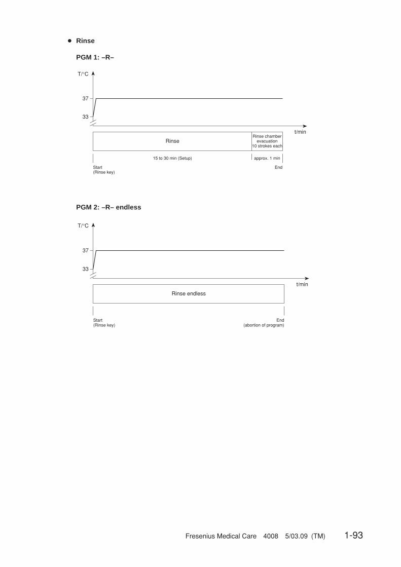
Fresenius Medical Care 4008 5/03.09 (TM) 1-93
● Rinse
PGM 1: –R–
PGM 2: –R– endless
33
37
T/°C
t/min
RinseRinse chamber
evacuation10 strokes each
approx. 1 min15 to 30 min (Setup)
Start(Rinse key)
End
33
37
T/°C
t/min
Rinse endless
Start(Rinse key)
End(abortion of program)
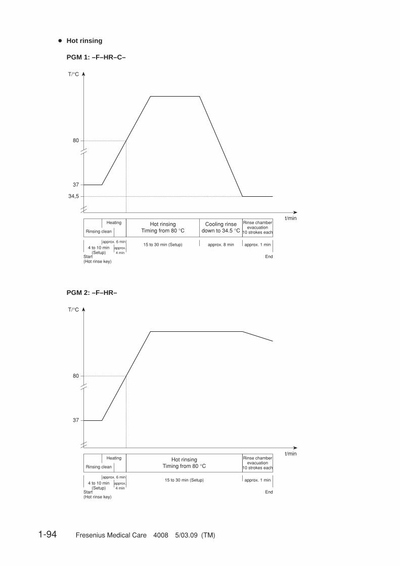
1-94 Fresenius Medical Care 4008 5/03.09 (TM)
● Hot rinsing
PGM 1: –F–HR–C–
PGM 2: –F–HR–
37
t/minHot rinsing
Timing from 80 °CRinse chamber
evacuation10 strokes each
approx. 1 min15 to 30 min (Setup)
Start (Hot rinse key)
End
T/°C
80
34,5
Heating
Rinsing clean
Cooling rinsedown to 34.5 °C
approx. 8 minapprox. 6 min
4 to 10 min(Setup)
approx.4 min
37
t/minHot rinsing
Timing from 80 °CRinse chamber
evacuation10 strokes each
approx. 1 min15 to 30 min (Setup)
Start (Hot rinse key)
End
T/°C
80
Heating
Rinsing clean
approx. 6 min
4 to 10 min(Setup)
approx.4 min
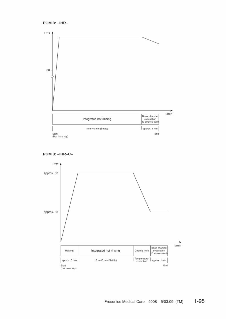
Fresenius Medical Care 4008 5/03.09 (TM) 1-95
PGM 3: –IHR–
t/min
Integrated hot rinsingRinse chamber
evacuation10 strokes each
approx. 1 min15 to 40 min (Setup)
Start(Hot rinse key)
End
T/°C
80
t/min
Integrated hot rinsingRinse chamber
evacuation10 strokes each
approx. 1 min15 to 40 min (SetUp)
Start(Hot rinse key)
End
T/°C
approx. 35
approx. 80
approx. 5 min
Heating Cooling rinse
Temperature-controlled
PGM 3: –IHR–C–
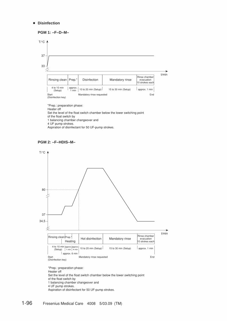
1-96 Fresenius Medical Care 4008 5/03.09 (TM)
● Disinfection
PGM 1: –F–D–M–
PGM 2: –F–HDIS–M–
33
37
T/°C
t/min
Rinsing cleanRinse chamber
evacuation10 strokes each
approx. 1 min10 to 20 min (Setup)
Start(Disinfection key)
End
Disinfection Mandatory rinsePrep.*
15 to 30 min (Setup)approx.1 min
4 to 10 min(Setup)
*Prep.: preparation phase:Heater offSet the level of the float switch chamber below the lower switching point of the float switch by1 balancing chamber changeover and4 UF pump strokes.Aspiration of disinfectant for 50 UF-pump strokes.
Mandatory rinse requested
37
t/minRinsing clean Rinse chamber
evacuation10 strokes each
approx. 1 min10 to 20 min (Setup)
Start(Disinfection key)
End
Hot disinfection Mandatory rinsePrep.*
15 to 30 min (Setup)approx.1 min
4 to 10 min(Setup)
*Prep.: preparation phase:Heater offSet the level of the float switch chamber below the lower switching point of the float switch by1 balancing chamber changeover and4 UF pump strokes.Aspiration of disinfectant for 50 UF-pump strokes.
approx. 6 minMandatory rinse requested
T/°C
80
Heating
34,5
approx.4 min
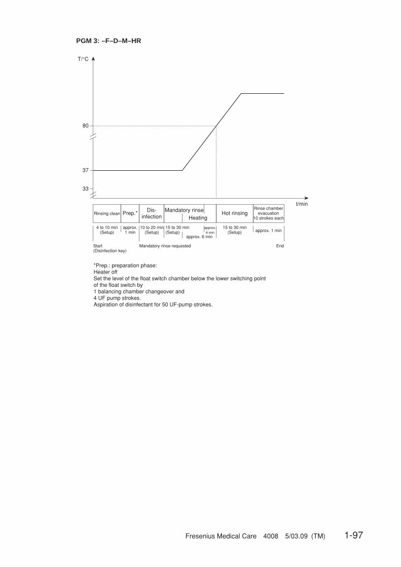
Fresenius Medical Care 4008 5/03.09 (TM) 1-97
PGM 3: –F–D–M–HR
33
37
t/min
Rinsing cleanRinse chamber
evacuation10 strokes each
approx. 1 min10 to 20 min
(Setup)
Start(Disinfection key)
End
Dis-infection
Mandatory rinsePrep.*
15 to 30 min(Setup)
approx.1 min
4 to 10 min(Setup)
*Prep.: preparation phase:Heater offSet the level of the float switch chamber below the lower switching point of the float switch by1 balancing chamber changeover and4 UF pump strokes.Aspiration of disinfectant for 50 UF-pump strokes.
Mandatory rinse requested
HeatingHot rinsing
approx.4 min
15 to 30 min(Setup)
approx. 6 min
T/°C
80

1-98 Fresenius Medical Care 4008 5/03.09 (TM)
PGM 4: –F–HDIS–M–HR–
PGM 5: –F–D(F)–M–
37
t/minRinsing clean
10 to 20 min(Setup)
Start(Disinfection key)
Hotdisinfection
Prep.*
approx.1 min
4 to 10 min(Setup)
*Prep.: preparation phase:Heater offSet the level of the float switch chamber below the lower switching point of the float switch by1 balancing chamber changeover and4 UF pump strokes.Aspiration of disinfectant for 50 UF-pump strokes.
approx. 6 minMandatory rinse requested
T/°C
80
Heating
Rinse chamberevacuation
10 strokes each
approx. 1 min
End
Mandatory rinse
15 to 30 min(Setup)
HeatingHot
rinsing
approx.4 min
15 to 30 min(Setup)
approx. 6 min
approx.4 min
33
37
T/°C
t/min
Rinsing cleanRinse chamber
evacuation10 strokes each
approx. 1 min10 to 20 min (Setup)
Start(Disinfection key)
End
Disinfection Mandatory rinsePrep.*
15 to 30 min (Setup)approx.1 min
4 to 10 min(Setup)
*Prep.: preparation phase:Heater offSet the level of the float switch chamber below the lower switching point of the float switch by 23 UF pump strokes.Aspiration of disinfectant for32 concentrate pump strokes à 330 steps.
Mandatory rinse requested

Fresenius Medical Care 4008 5/03.09 (TM) 2-1
Table of Contents2 Technical Safety Checks / Maintenance
Section Page
2.1 Technical Safety Checks and Maintenancefor 4008 hemodialysis systems and options ............................................................. 2-3
2.1.1 Important notes ............................................................................................................... 2-32.1.2 Description – Technical Safety Checks and Maintenance ............................................. 2-52.1.3 Report – Technical Safety Checks and Maintenance .................................................... 2-162.1.4 Notes – Check of the electrical safety ............................................................................ 2-21
2.2 TSC report ..................................................................................................................... 2-25

2-2 Fresenius Medical Care 4008 5/03.09 (TM)

Fresenius Medical Care 4008 5/03.09 (TM) 2-3
2.1 Technical Safety Checks and Maintenancefor 4008 hemodialysis systems and options
2.1.1 Important notes
This chapter lists all necessary Technical Safety Checks (TSC) and Maintenance procedures(MA).
These checks must be performed every 24 months if all of the following requirements have beenmet:– Unique assignment of the rotors to the appropriate line roller pumps– Software:
4008 E/B systems: from 4.951 to < 5.00 or with 5.201 or higher4008 H/S systems: from 2.951 to < 3.00 or with 4.311 or higher
– DIP switch P.C.B. LP 632 array 2 SW 5 set to OFF.– DIP switch P.C.B. LP 631 array 2 SW 7 set to ON.– DIP switch P.C.B. LP 631 array 2 SW 8 set to ON. (With CDS option only)– Heater rod made of TitaniumIf one of the requirements mentioned above has not been met, the checks have to be performedevery 12 months.
Performance of the Technical Safety Checks must be recorded in the Medical Device Register.
Please refer to page 2-5 to page 2-14 for the description of the Technical Safety Checks andMaintenance.
Please refer to the pages 2-29 and 2-30 for the report for the Technical Safety Checks andMaintenance. Numbers not listed are not part of the TSC. These are part of the Maintenanceprocedures (MA).
Instructions to be observed when servicing the system
Assembly, extensions, adjustments, modifications or repairs may only be carried out by themanufacturer or persons authorized by him.
The activities described in the Technical Manual require the availability of the necessary technicaltest equipment and accessories.
When working on the open system, the following precautions must be respected:– Protect the components against ingress of fluids.– Do not touch live parts (e. g. connectors of the power cable or heater).
When repairing and when replacing spare parts, observe the applicable ESD precautions(e.g. EN 100 015-1).

2-4 Fresenius Medical Care 4008 5/03.09 (TM)
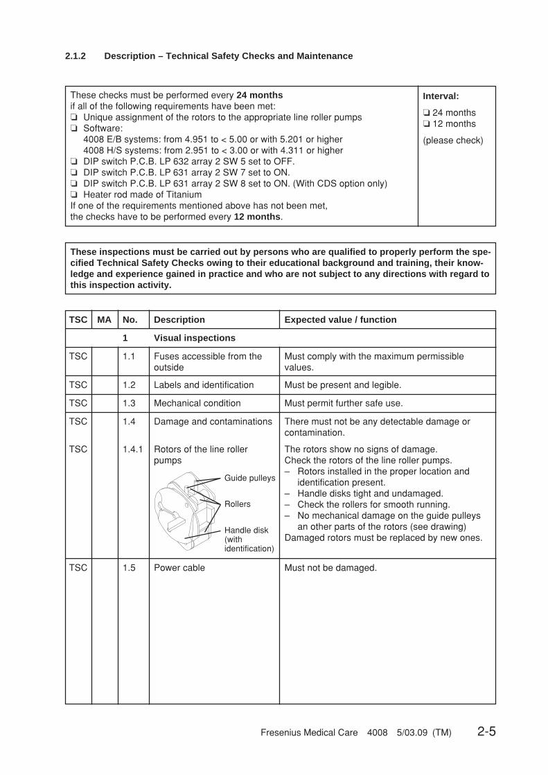
Fresenius Medical Care 4008 5/03.09 (TM) 2-5
These inspections must be carried out by persons who are qualified to properly perform the spe-cified Technical Safety Checks owing to their educational background and training, their know-ledge and experience gained in practice and who are not subject to any directions with regard tothis inspection activity.
2.1.2 Description – Technical Safety Checks and Maintenance
TSC MA No. Description Expected value / function
1 Visual inspections
TSC 1.1
TSC 1.3 Mechanical condition Must permit further safe use.
Fuses accessible from theoutside
Must comply with the maximum permissiblevalues.
TSC 1.2 Labels and identification Must be present and legible.
TSC
TSC
1.4
1.4.1
Damage and contaminations
Rotors of the line rollerpumps
There must not be any detectable damage orcontamination.
The rotors show no signs of damage.Check the rotors of the line roller pumps.– Rotors installed in the proper location and
identification present.– Handle disks tight and undamaged.– Check the rollers for smooth running.– No mechanical damage on the guide pulleys
an other parts of the rotors (see drawing)Damaged rotors must be replaced by new ones.
Guide pulleys
Rollers
Handle disk(withidentification)
TSC 1.5 Power cable Must not be damaged.
These checks must be performed every 24 monthsif all of the following requirements have been met:❏ Unique assignment of the rotors to the appropriate line roller pumps❏ Software:
4008 E/B systems: from 4.951 to < 5.00 or with 5.201 or higher4008 H/S systems: from 2.951 to < 3.00 or with 4.311 or higher
❏ DIP switch P.C.B. LP 632 array 2 SW 5 set to OFF.❏ DIP switch P.C.B. LP 631 array 2 SW 7 set to ON.❏ DIP switch P.C.B. LP 631 array 2 SW 8 set to ON. (With CDS option only)❏ Heater rod made of TitaniumIf one of the requirements mentioned above has not been met,the checks have to be performed every 12 months.
Interval:
❏ 24 months❏ 12 months
(please check)

2-6 Fresenius Medical Care 4008 5/03.09 (TM)
Replace the sealing in the concentrate/bicarbonate suction tubes and lubricatewith silicone paste. Replace the rivet in the suction tubes, if necessary.Check the rubber in the rinse chambers for proper function.Replace the filters of the suction tubes (71/72).Retighten the rinse chamber (90a/90b) screws.Replace the check valve (92).When using CDS, replace the check valves (117/118) and the filters 119/120.Replace the filter sieves; upstream of the UF pump (filter 74), downstream ofMV43 (filter 76), between MV99 and rinse chamber (filter 149), between MV100and rinse chamber (filter 148).Replace the filter sieve in the dialyzer line; replace the complete filter (73), ifnecessary.Replace the O-rings in the dialyzer couplings.Check the line in the sampling valve (116) dialysate circuit for proper function, re-place the complete valve, if necessary.Clean or replace the fan filter in the monitor.Check the air separation pump (97): replace the belt ribbon and the line segment.Observe direction of delivery.MV 84 must be replaced after 2 years.Only if Puristeril is used.Replace the connecting piece or equilibration chamber.Only for systems in which the ONLINEplus™ option or the DIASAFE®plus option isnot used.Replace filter 210 (if present).Replace the filter of the disinfectant suction tube.Replace worn or dirty tubings.
1.6.1
1.6.21.6.31.6.41.6.5
1.6.6
1.6.7
1.6.81.6.9
1.6.101.6.11
1.6.12
1.6.13
1.6.141.6.151.6.16
MA
MAMAMAMA
MA
MA
MAMA
MAMA
MA
MA
MAMAMA
MA 1.6 Preventive Maintenance procedures
2 General checks
TSC 2.1 Power failure alarm Dialysis mode;Continuous sound after removing the power plug.Text displayed: Emergency operationThe extracorporeal blood circuit incl. all monito-ring functions is maintained.
TSC 2.2 Check level sensor Draw in air via the dialysate couplings.The air separation pump is activated.If more air is detected, the system will switch tothe fill program, depending on the dialysate flow.Text displayed when the OD senses opaque fluid:Fillprogram
TSC 2.3 Check DIP switches P.C.B. LP 631 (CPU1) DIP switch array 2 SW7 isset to ON.With central delivery system:P.C.B. LP 631 (CPU1) DIP switch array 2 SW8 isset to ON.
TSC MA No. Description Expected value / function
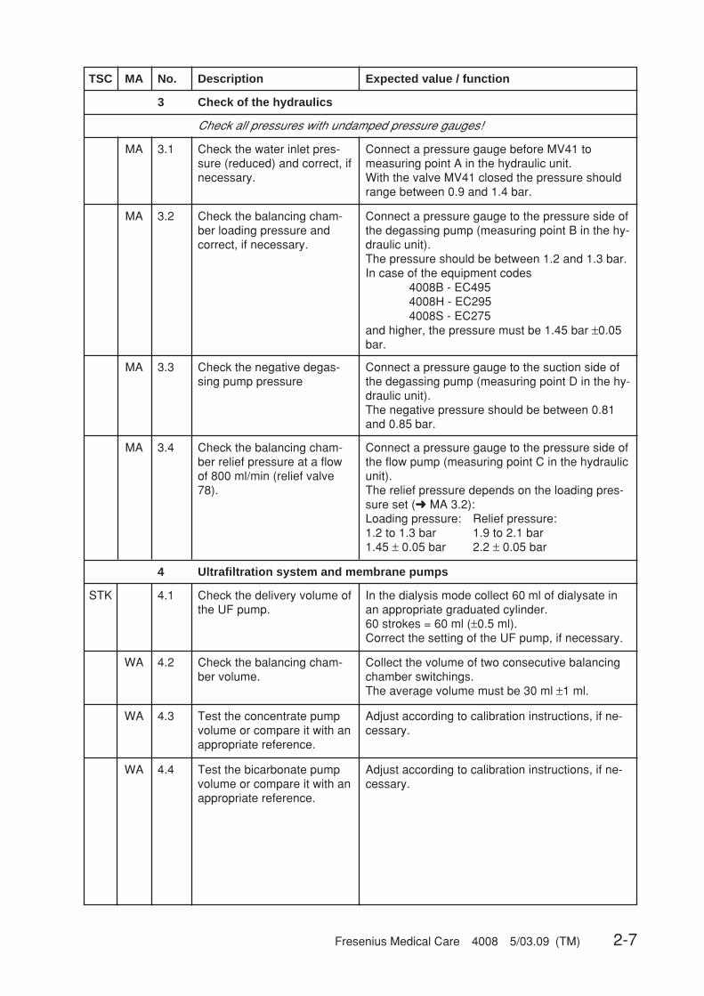
Fresenius Medical Care 4008 5/03.09 (TM) 2-7
Connect a pressure gauge to the pressure side ofthe flow pump (measuring point C in the hydraulicunit).The relief pressure depends on the loading pres-sure set (➜ MA 3.2):Loading pressure: Relief pressure:1.2 to 1.3 bar 1.9 to 2.1 bar1.45 ± 0.05 bar 2.2 ± 0.05 bar
Check the balancing cham-ber relief pressure at a flowof 800 ml/min (relief valve78).
3 Check of the hydraulics
MA 3.1 Check the water inlet pres-sure (reduced) and correct, ifnecessary.
Connect a pressure gauge before MV41 tomeasuring point A in the hydraulic unit.With the valve MV41 closed the pressure shouldrange between 0.9 and 1.4 bar.
MA 3.2 Check the balancing cham-ber loading pressure andcorrect, if necessary.
Connect a pressure gauge to the pressure side ofthe degassing pump (measuring point B in the hy-draulic unit).The pressure should be between 1.2 and 1.3 bar.In case of the equipment codes
4008B - EC4954008H - EC2954008S - EC275
and higher, the pressure must be 1.45 bar ±0.05bar.
MA 3.3 Check the negative degas-sing pump pressure
Connect a pressure gauge to the suction side ofthe degassing pump (measuring point D in the hy-draulic unit).The negative pressure should be between 0.81and 0.85 bar.
MA 3.4
Check all pressures with undamped pressure gauges!
TSC MA No. Description Expected value / function
4 Ultrafiltration system and membrane pumps
STK 4.1 Check the delivery volume ofthe UF pump.
In the dialysis mode collect 60 ml of dialysate inan appropriate graduated cylinder.60 strokes = 60 ml (±0.5 ml).Correct the setting of the UF pump, if necessary.
WA 4.2 Check the balancing cham-ber volume.
Collect the volume of two consecutive balancingchamber switchings.The average volume must be 30 ml ±1 ml.
WA 4.3 Test the concentrate pumpvolume or compare it with anappropriate reference.
Adjust according to calibration instructions, if ne-cessary.
WA 4.4 Test the bicarbonate pumpvolume or compare it with anappropriate reference.
Adjust according to calibration instructions, if ne-cessary.

2-8 Fresenius Medical Care 4008 5/03.09 (TM)
TSC MA No. Description Expected value / function
5 Dialysis mode
MA 5.1 Temperature Use a reference meter connected between thedialyzer couplings to verify that the temperature is37 °C ±0.5 °C.Correct any deviations with the calibration pro-gram.
MA 5.2 Temperature display(not applicable for 4008 B /4008 S)
The temperature shown on the monitor front pa-nel must be 37 °C ±0.5 °C.Correct any deviations with the calibration pro-gram.
MA 5.4 Dialysate pressure Perform a TMP test according to the calibrationinstructions.(part 14 CAL. DIAL. PRESSURE)
MA 5.3 Verify the dialysate flow300/500/800 ml/min
Collect fluid on the drain using a measuring cylin-der.800 ml/min (desired value: 765 to 837 ml/min)500 ml/min (desired value: 471 to 528 ml/min)300 ml/min (desired value: 279 to 321 ml/min)Adjust according to calibration instructions, if ne-cessary.
TSC 5.5 Verify the conductivity dis-play
When the bibag® option is used, connect abibag®!Measure the conductivity with a reference meterconnected between the dialyzer couplings.The conductivity measured must agree with thevalue on the reference meter.Correct any deviations with the calibration pro-gram.
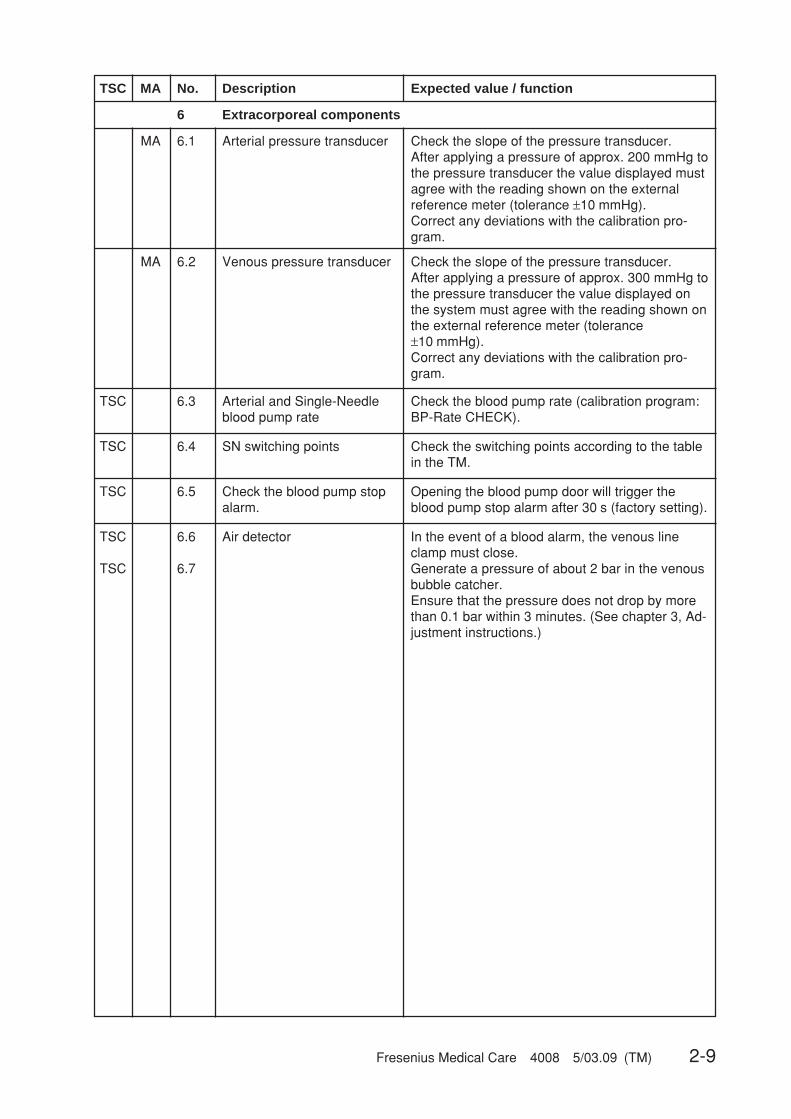
Fresenius Medical Care 4008 5/03.09 (TM) 2-9
Check the slope of the pressure transducer.After applying a pressure of approx. 300 mmHg tothe pressure transducer the value displayed onthe system must agree with the reading shown onthe external reference meter (tolerance±10 mmHg).Correct any deviations with the calibration pro-gram.
6 Extracorporeal components
MA 6.1 Arterial pressure transducer Check the slope of the pressure transducer.After applying a pressure of approx. 200 mmHg tothe pressure transducer the value displayed mustagree with the reading shown on the externalreference meter (tolerance ±10 mmHg).Correct any deviations with the calibration pro-gram.
MA 6.2 Venous pressure transducer
TSC MA No. Description Expected value / function
TSC 6.3 Arterial and Single-Needleblood pump rate
Check the blood pump rate (calibration program:BP-Rate CHECK).
TSC 6.4 SN switching points Check the switching points according to the tablein the TM.
TSC 6.5 Check the blood pump stopalarm.
Opening the blood pump door will trigger theblood pump stop alarm after 30 s (factory setting).
TSC
TSC
6.6
6.7
Air detector In the event of a blood alarm, the venous lineclamp must close.Generate a pressure of about 2 bar in the venousbubble catcher.Ensure that the pressure does not drop by morethan 0.1 bar within 3 minutes. (See chapter 3, Ad-justment instructions.)

2-10 Fresenius Medical Care 4008 5/03.09 (TM)
TSC MA No. Description Expected value / function
7 Options
7.1 bibag®
MA 7.1.1 bibag® connector Replace the O-rings.
MA 7.1.2 PSW 134 Check the switching pressure.The maximum switching pressure is130 mbar + 30 mbar.
7.2 DIASAFE
MA 7.2.1 DIASAFE filter life Check the filter life.Filter life: 12 weeks
MA 7.2.2 Hydrophobic filter 111 Replace the filter.
MA 7.2.3 O-rings in the dialysatecouplings of the DIASAFE
Replace the O-rings.
7.3 DIASAFE®plus
MA 7.3.1 DIASAFE®plus filter life Check the filter life.Filter life: 12 weeks
MA 7.3.2 Hydrophobic filter 111 Replace the filter.
7.4 4008 HDF
TSC 7.4.1 Check the delivery rate ofthe 2nd UF pump.
Collect 60 ml of dialysate in the dialysis modeusing an appropriate measuring cylinder.60 strokes = 60 ml (±0.5 ml)If necessary, correct the value.

Fresenius Medical Care 4008 5/03.09 (TM) 2-11
TSC MA No. Description Expected value / function
7.5 ON-LINE-HDF (and DIASAFE)
MA 7.5.1 Filter life of DIASAFE andON-LINE filter
Check the filter life.Filter life of the DIASAFE:12 weeksFilter life of ON-LINE filter:8 weeks or 50 treatments
MA 7.5.2 Hydrophobic filter 111 Replace the filter.
MA 7.5.3 O-rings in the dialysatecouplings of the DIASAFE
Replace the O-rings.
MA 7.5.4 HDF pump rotor Check the rotor for smooth running and wear.
MA 7.5.5 Fastening strap Check the fastening strap for Luer-lock.
TSC 7.5.6 Substituate pump(part no. 672 521 1)with DC motor
or
Substituate pump(part no. 674 982 1)with stepper motor
Speed 150 ml/minTo determine the delivery volume:the volume of fluid delivered must agree with thepreset value (±10 %).To check the speed:with the above setting the blood pump rotor mustturn at 13.5 rpm.(See Technical Manual ON-LINE-HDF,chapter 3).
Check the pump rate (calibration program:BP-Rate CHECK).
TSC 7.5.7 Substituate pump stop Stop the substituate pump by– triggering a blood alarm,– triggering the bypass function,– opening the blood pump door.
TSC 7.5.8 Substituate pump function– Rinse
– Hot rinse
– Disinfection
Start the rinse program;the pump will deliver at 400 ml/min.Start the hot rinse program;the pump will deliver at 150 ml/min.Start the disinfection program;the pump will deliver at 400 ml/min.
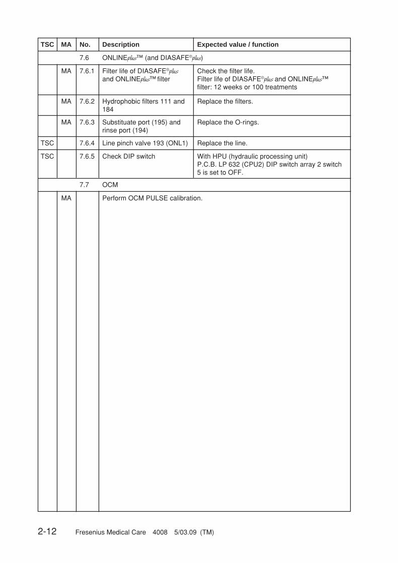
2-12 Fresenius Medical Care 4008 5/03.09 (TM)
TSC 7.6.5 Check DIP switch With HPU (hydraulic processing unit)P.C.B. LP 632 (CPU2) DIP switch array 2 switch5 is set to OFF.
TSC MA No. Description Expected value / function
7.6 ONLINEplus™ (and DIASAFE®plus)
MA 7.6.1 Filter life of DIASAFE®plusand ONLINEplus™ filter
Check the filter life.Filter life of DIASAFE®plus and ONLINEplus™filter: 12 weeks or 100 treatments
MA 7.6.2 Hydrophobic filters 111 and184
Replace the filters.
MA 7.6.3 Substituate port (195) andrinse port (194)
Replace the O-rings.
TSC 7.6.4 Line pinch valve 193 (ONL1) Replace the line.
7.7 OCM
Perform OCM PULSE calibration.MA

Fresenius Medical Care 4008 5/03.09 (TM) 2-13
TSC MA No. Description Expected value / function
7.8 BPM 4008
MA 7.8.1 Labels and indications Must be present and clearly legible.Check of the actual condition.
MA 7.8.2 Mechanical condition Must permit further safe use.
MAMA
MA
7.8.2.17.8.2.2
7.8.2.3
Check whether the line connector is correctly attached to the system.Check whether the internal blood pressure module, the printed circuit boards andall cable connections are correctly fixed.Replace damaged lines or cuffs.
MA 7.8.2.4 Indicating elements Visual and audible functional checks after turn-on.(See Operating Instructions BPM 4008, chapter2.2)
MA 7.8.2.5 Touch panel Check whether the touch panel is functioning cor-rectly.
TSC 7.8.3 Leakage test Perform the leakage test with cuff and pressureline connected.The pressure leakage rate must be less than6 mmHg/min.(See Technical Manual BPM 4008, chapter 3.1)
TSC 7.8.4 Calibration Calibration:Pressure values: Tolerance:250 mmHg ±5 mmHg200 mmHg ±4 mmHg150 mmHg ±3 mmHg100 mmHg ±3 mmHg050 mmHg ±3 mmHg(See Technical Manual BPM 4008, chapter 3.2)
TSC 7.8.5 Safety valve Check the safety valve.The system must be discharged at320 mmHg ± 10 mmHg.(See Technical Manual BPM 4008, chapter 3.3)
TSC 7.8.6 Measuring of blood pressure Measure the blood pressure in the manual mode.Check the results for plausibility.
7.9 BTM 4008
No further Technical Safety Checks and Maintenance procedures must be per-formed.
7.10 BVM 4008
No further Technical Safety Checks and Maintenance procedures must be per-formed.

2-14 Fresenius Medical Care 4008 5/03.09 (TM)
PE
L
N
M 1
L (N)
N (L)
L
N
PE MD
TSC MA No. Description Expected value / function
8 Check of the electrical safetyIn Germany according to DIN VDE 0751 standard – 1st edition 10/2001.In other countries, observe the local regulations!
TSC 8.2 Protective earth resistance Max. 0.3 Ω (with power cable)
TSC 8.3 Measurement of the leakage current (device leakage current)
Differential current measurement according to fig. C.6
For measuring points, see 2.1.4 Notes – Check of the electrical safety.
TSC 8.1 Visual inspections performed see item 1 Visual inspections
or
Direct measurement according to fig. C.5
Basic conditions:– Measurement of the protective earth resistance has been completed.– Perform the measurement with the system being at operating temperature
in the Dialysis or Preparation operation mode.– Dialysate:
Dialysis temperature ≥ 37°CDialysate flow ≥ 300 ml/minConductivity ≥ 13 mS/cm
– When performing a direct measurement, the following precautions must beobserved:The system must be installed under insulated conditions.All external connections must have been removed from the system.
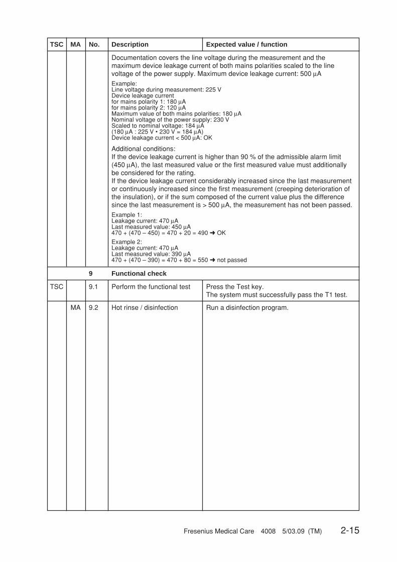
Fresenius Medical Care 4008 5/03.09 (TM) 2-15
Documentation covers the line voltage during the measurement and themaximum device leakage current of both mains polarities scaled to the linevoltage of the power supply. Maximum device leakage current: 500 μA
Example:Line voltage during measurement: 225 VDevice leakage currentfor mains polarity 1: 180 μAfor mains polarity 2: 120 μAMaximum value of both mains polarities: 180 μANominal voltage of the power supply: 230 VScaled to nominal voltage: 184 μA(180 μA : 225 V • 230 V = 184 μA)Device leakage current < 500 μA: OK
Additional conditions:If the device leakage current is higher than 90 % of the admissible alarm limit(450 μA), the last measured value or the first measured value must additionallybe considered for the rating.If the device leakage current considerably increased since the last measurementor continuously increased since the first measurement (creeping deterioration ofthe insulation), or if the sum composed of the current value plus the differencesince the last measurement is > 500 μA, the measurement has not been passed.
Example 1:Leakage current: 470 μALast measured value: 450 μA470 + (470 – 450) = 470 + 20 = 490 ➜ OK
Example 2:Leakage current: 470 μALast measured value: 390 μA470 + (470 – 390) = 470 + 80 = 550 ➜ not passed
9 Functional check
TSC 9.1 Perform the functional test Press the Test key.The system must successfully pass the T1 test.
MA 9.2 Hot rinse / disinfection Run a disinfection program.
TSC MA No. Description Expected value / function

2-16 Fresenius Medical Care 4008 5/03.09 (TM)
1 Visual checksTSC 1.1 Fuses accessible from the outside comply with the indicated values................................ ❏TSC 1.2 Labels and identifications present and legible ................................................................... ❏TSC 1.3 Mechanical conditions permits further safe use ................................................................. ❏TSC 1.4 No damage or contaminations detectable ......................................................................... ❏TSC 1.4.1 The rotors of the line roller pumps show no signs of damage ........................................... ❏TSC 1.5 Power cable not damaged ................................................................................................. ❏
1.6 Preventive Maintenance proceduresMA 1.6.1 Sealing in the suction tubes changed and lubricated, rivet replaced ................................ ❏MA 1.6.2 Rubber in rinse chambers checked for proper function ..................................................... ❏MA 1.6.3 Suction tube filters replaced ............................................................................................... ❏MA 1.6.4 Rinse chamber screws tight ............................................................................................... ❏MA 1.6.5 Check valve replaced ......................................................................................................... ❏MA 1.6.6 Pre-UF pump filter, filter downstream of MV43, filter between rinse chambers,
and on MV99, MV100, CDS and disinfectant port replaced .............................................. ❏MA 1.6.7 Dialysate filter replaced or sieve changed ......................................................................... ❏MA 1.6.8 O-rings in dialyzer couplings replaced ............................................................................... ❏MA 1.6.9 Sampling valve functions properly ..................................................................................... ❏MA 1.6.10 Fan filter replaced............................................................................................................... ❏MA 1.6.11 Ribbon belt and line segment in air separation pump changed ......................................... ❏MA 1.6.12 MV84, replaced after 2 years. (Only if Puristeril is used.) ................................................. ❏MA 1.6.13 Connecting piece or equilibration chamber replaced.
(Only if ONLINE™plus or DIASAFE®plus option is not used.) .............................................. ❏MA 1.6.14 Filter 210 replaced (if present) ........................................................................................... ❏MA 1.6.15 Filter of the disinfectant suction tube replaced .................................................................. ❏MA 1.6.16 No dirty or worn tubings ..................................................................................................... ❏
2.1.3 Report – Technical Safety Checks and Maintenance
Service report no.:Customer/Customer no.:
Serial no.: Inventory no.: Operating hours:
System type: 4008 ❏ 4008 B ❏ 4008 H ❏ 4008 S ❏
With option: SN ❏ bibag® ❏ 4008 HDF ❏ ON-LINE-HDF ❏ ONLINEplusplusplusplusplus™ ❏ BTM ❏BPM ❏ BVM ❏ DIASAFE ❏ DIASAFE®plusplusplusplusplus ❏ OCM ❏
These checks must be performed every 24 monthsif all of the following requirements have been met:❏ Unique assignment of the rotors to the appropriate line roller pumps❏ Software:
4008 E/B systems: from 4.951 to < 5.00 or with 5.201 or higher4008 H/S systems: from 2.951 to < 3.00 or with 4.311 or higher
❏ DIP switch P.C.B. LP 632 array 2 SW 5 set to OFF.❏ DIP switch P.C.B. LP 631 array 2 SW 7 set to ON.❏ DIP switch P.C.B. LP 631 array 2 SW 8 set to ON. (With CDS option only)❏ Heater rod made of TitaniumIf one of the requirements mentioned above has not been met,the checks have to be performed every 12 months.
Interval:
❏ 24 months❏ 12 months
(please check)

Fresenius Medical Care 4008 5/03.09 (TM) 2-17
2 General checksTSC 2.1 Power failure alarm – continous sound – display: Emergency operation .......................... ❏TSC 2.2 Air separation by air separation pump activated;
display if more air must be separated and OD senses opaque fluid: fill program ............. ❏TSC 2.3 Check DIP switches
P.C.B. LP 631 (CPU1) DIP switch array 2 SW7 is set to ON.With central delivery system:P.C.B. LP 631 (CPU1) DIP switch array 2 SW8 is set to ON. ........................................... ❏
3 Check of the hydraulicsMA 3.1 Water inlet pressure (reduced) 0.9 bar to 1.4 bar ................... Measured value:________ ❏MA 3.2 Loading pressure 1.25 bar ±0.05 bar ...................................... Measured value:________ ❏
With EC495 (4008B); EC295(4008H), EC 275 (4008S) and higherLoading pressure 1.45 bar ±0.05 bar ...................................... Measured value:________ ❏
MA 3.3 Negative degassing pump pressure 0.81 to 0.85 bar ............. Measured value:________ ❏MA 3.4 Balancing chamber relief pressure at 800 ml/min ................... Measured value:________ ❏
Loading pressure: Relief pressure:1.2 to 1.3 bar 1.9 to 2.1 bar1.45 ± 0.05 bar 2.2 ± 0.05 bar
4 Ultrafiltration system and membrane pumpsTSC 4.1 UF pump, 1 stroke = 1 ml, 60 strokes = 60 ml ±0.5 ml ........... Measured value:________ ❏MA 4.2 Average balancing chamber volume 30 ± 1 ml ....................... Measured value:________ ❏MA 4.3 Concentrate pump calibration volume removal /
number of strokes .................................................................... Measured value:________ ❏MA 4.4 Bicarbonate pump calibration volume removal /
number of strokes .................................................................... Measured value:________ ❏
5 Dialysis modeMA 5.1 Expected temperature 37 °C ± 0.5 °C ..................................... Measured value:________ ❏MA 5.2 Temperature display 37 °C ± 0.5 °C ....................................... Measured value:________ ❏MA 5.3 Dialysate flow check
800 ml/min (desired value: 765 to 837 ml/min) ................... Measured value:________ ❏500 ml/min (desired value: 471 to 528 ml/min) ................... Measured value:________ ❏300 ml/min (desired value: 279 to 321 ml/min) ................... Measured value:________ ❏
MA 5.4 Dialysate pressure– Check zero point with flow off ......................................................................................... ❏– Slope checked ................................................................................................................ ❏
TSC 5.5 Conductivity display checked with reference meter ........................................................... ❏If the bibag® option is used, connect a bibag®!– CD system ........................................................................... Measured value:________ ❏– CD ref. ................................................................................. Measured value:________ ❏
6 Extracorporeal componentsMA 6.1 Arterial pressure displayed checked with reference meter ................................................ ❏MA 6.2 Venous pressure displayed checked with reference meter ............................................... ❏TSC 6.3 Blood pumps: blood pump rate checked (calibration program: BP-Rate CHECK)............ ❏TSC 6.4 SN switching pressure checked according to table in TM ................................................. ❏TSC 6.5 Blood pump stop alarm checked ........................................................................................ ❏TSC 6.6 Venous line clamp closes after blood alarm ...................................................................... ❏TSC 6.7 Pressure of about 2 bar in the venous bubble catcher ...................................................... ❏
Pressure must not drop by more than 0.1 bar within 3 minutes. ....................................... ❏
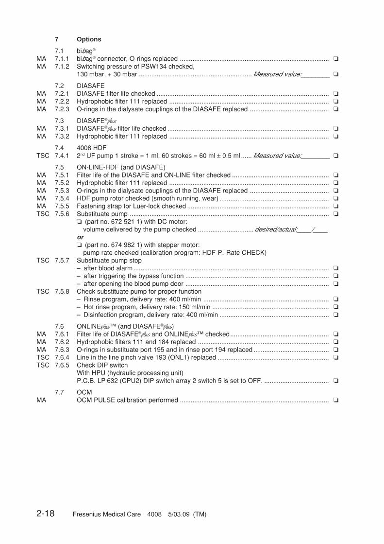
2-18 Fresenius Medical Care 4008 5/03.09 (TM)
7 Options
7.1 bibag®
MA 7.1.1 bibag® connector, O-rings replaced ................................................................................... ❏MA 7.1.2 Switching pressure of PSW134 checked,
130 mbar, + 30 mbar ............................................................... Measured value:________ ❏
7.2 DIASAFEMA 7.2.1 DIASAFE filter life checked ................................................................................................ ❏MA 7.2.2 Hydrophobic filter 111 replaced ......................................................................................... ❏MA 7.2.3 O-rings in the dialysate couplings of the DIASAFE replaced ............................................ ❏
7.3 DIASAFE®plusMA 7.3.1 DIASAFE®plus filter life checked .......................................................................................... ❏MA 7.3.2 Hydrophobic filter 111 replaced ......................................................................................... ❏
7.4 4008 HDFTSC 7.4.1 2nd UF pump 1 stroke = 1 ml, 60 strokes = 60 ml ± 0.5 ml ...... Measured value:________ ❏
7.5 ON-LINE-HDF (and DIASAFE)MA 7.5.1 Filter life of the DIASAFE and ON-LINE filter checked ...................................................... ❏MA 7.5.2 Hydrophobic filter 111 replaced ......................................................................................... ❏MA 7.5.3 O-rings in the dialysate couplings of the DIASAFE replaced ............................................ ❏MA 7.5.4 HDF pump rotor checked (smooth running, wear) ............................................................. ❏MA 7.5.5 Fastening strap for Luer-lock checked ............................................................................... ❏TSC 7.5.6 Substituate pump ............................................................................................................... ❏
❏ (part no. 672 521 1) with DC motor:volume delivered by the pump checked ............................... desired/actual:____/____
or❏ (part no. 674 982 1) with stepper motor:
pump rate checked (calibration program: HDF-P.-Rate CHECK)TSC 7.5.7 Substituate pump stop
– after blood alarm............................................................................................................. ❏– after triggering the bypass function ................................................................................ ❏– after opening the blood pump door ................................................................................ ❏
TSC 7.5.8 Check substituate pump for proper function– Rinse program, delivery rate: 400 ml/min ...................................................................... ❏– Hot rinse program, delivery rate: 150 ml/min ................................................................. ❏– Disinfection program, delivery rate: 400 ml/min ............................................................. ❏
7.6 ONLINEplus™ (and DIASAFE®plus)MA 7.6.1 Filter life of DIASAFE®plus and ONLINEplus™ checked....................................................... ❏MA 7.6.2 Hydrophobic filters 111 and 184 replaced ......................................................................... ❏MA 7.6.3 O-rings in substituate port 195 and in rinse port 194 replaced .......................................... ❏TSC 7.6.4 Line in the line pinch valve 193 (ONL1) replaced .............................................................. ❏TSC 7.6.5 Check DIP switch
With HPU (hydraulic processing unit)P.C.B. LP 632 (CPU2) DIP switch array 2 switch 5 is set to OFF. .................................... ❏
7.7 OCMMA OCM PULSE calibration performed ................................................................................... ❏

Fresenius Medical Care 4008 5/03.09 (TM) 2-19
7.8 BPM 4008MA 7.8.1 Labels and indications are present and legible .................................................................. ❏MA 7.8.2 Mechanical condition permits further safe use .................................................................. ❏MA 7.8.2.1 Line connector is correctly fixed to the system .................................................................. ❏MA 7.8.2.2 Internal blood pressure module, printed circuit boards, cable connections are
correctly fixed ..................................................................................................................... ❏MA 7.8.2.3 Damaged lines or cuffs have been replaced...................................................................... ❏MA 7.8.2.4 Indicating elements checked .............................................................................................. ❏MA 7.8.2.5 Touch panel checked ......................................................................................................... ❏TSC 7.8.3 Leakage test: pressure leakage rate less than 6 mmHg/min ............................................. ❏TSC 7.8.4 Calibration:
Pressure values Tolerance250 mmHg ±5mmHg ..................................................... Measured value:________ ❏200 mmHg ±5mmHg ..................................................... Measured value:________ ❏150 mmHg ±3mmHg ..................................................... Measured value:________ ❏100 mmHg ±3mmHg ..................................................... Measured value:________ ❏050 mmHg ±3mmHg ..................................................... Measured value:________ ❏
TSC 7.8.5 Safety valve: discharge at 320 mmHg, ±10 mmHg ............................................................ ❏TSC 7.8.6 Blood pressure measured .................................................................................................. ❏
7.9 BTM 4008No further Technical Safety Checks and Maintenance procedures must be performed.
7.10 BVM 4008No further Technical Safety Checks and Maintenance procedures must be performed.
8 Check of the electrical safetyIn Germany according to DIN VDE 0751 standard – 1st Edition 10/2001.In other countries, observe the local regulations!
For measuring points, see 2.1.4 VDE check.For 4008 HDF option, check additional measuring point!
TSC 8.1 Visual inspections performed according to item 1 ............................................................. ❏
TSC 8.2 Protective earth resistance max. 0.3 Ω (with power cable) .... Measured value:________ ❏
TSC 8.3 Measurement of the leakage current ................................................................................. ❏❏ Differential current measurement according to fig. C.6or❏ Direct measurement according to fig. C.5
Nominal voltage of power supply ................... ________ VoltDevice leakage current mains polarity 1 ........ ________ μAfor line voltage ................................................ ________ Voltscaled to nominal voltage (maximum 500 μA,see also Additional conditions) ............................................. Measured value:________
Device leakage current mains polarity 2 ........ ________ μAfor line voltage ................................................ ________ Voltscaled to nominal voltage (maximum 500 μA,see also Additional conditions) ............................................. Measured value:________
Test equipment used: ______________________________
9 Final checksTSC 9.1 T1 test performed ............................................................................................................... ❏MA 9.2 Hot rinse / disinfection performed ...................................................................................... ❏

2-20 Fresenius Medical Care 4008 5/03.09 (TM)
Remarks:
Date: Signature: Stamp:
The system has been released for further use ❏ Yes ❏ No
Date: Signature: Stamp:
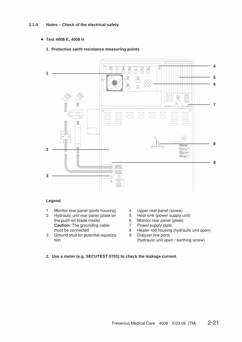
Fresenius Medical Care 4008 5/03.09 (TM) 2-21
2.1.4 Notes – Check of the electrical safety
● Test 4008 E, 4008 H
1. Protective earth resistance measuring points
5
3
2
1
4
6
7
8
9
4 Upper rear panel (screw)5 Heat sink (power supply unit)6 Monitor rear panel (plate)7 Power supply plate8 Heater rod housing (hydraulic unit open)9 Dialyzer line ports
(hydraulic unit open / earthing screw)
Legend
1 Monitor rear panel (ports housing)2 Hydraulic unit rear panel (plate on
the push-on blade inside)Caution: The grounding cablemust be connected.
3 Ground stud for potential equaliza-tion
2. Use a meter (e.g. SECUTEST 0701) to check the leakage current.
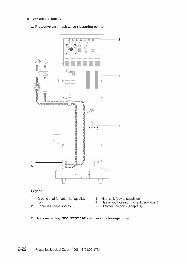
2-22 Fresenius Medical Care 4008 5/03.09 (TM)
3 Heat sink (power supply unit)4 Heater rod housing (hydraulic unit open)5 Dialyzer line ports (adapters)
Legend
1 Ground stud for potential equaliza-tion
2 Upper rear panel (screw)
● Test 4008 B, 4008 S
1. Protective earth resistance measuring points
2. Use a meter (e.g. SECUTEST 0701) to check the leakage current.
1
2
3
4
5

Fresenius Medical Care 4008 5/03.09 (TM) 2-23
● Test 4008 HDF (option)
1. Protective earth resistance measuring point
2. Use a meter (e.g. SECUTEST 0701) to check the leakage current.
3. Measurement conditions
The measurements must be taken in the dialysis mode in the “ON phase” of the heater controlsystem.The scales must be moved out to such an extent that neither of the two end switches are actuated(middle position).
Measuring pointProtective
earthresistance test

2-24 Fresenius Medical Care 4008 5/03.09 (TM)
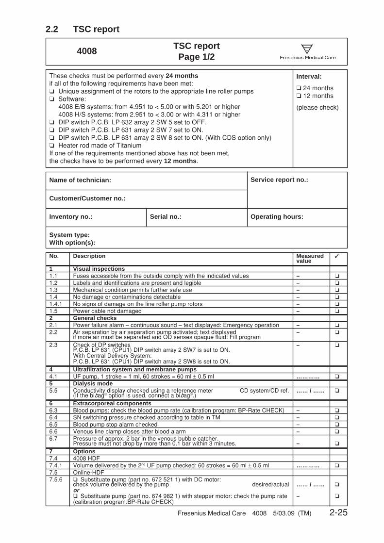
Fresenius Medical Care 4008 5/03.09 (TM) 2-25
2.2 TSC report
No. Description Measured ✓value
1 Visual inspections1.1 Fuses accessible from the outside comply with the indicated values – ❏
1.2 Labels and identifications are present and legible – ❏1.3 Mechanical condition permits further safe use – ❏
1.4 No damage or contaminations detectable – ❏
1.4.1 No signs of damage on the line roller pump rotors – ❏
1.5 Power cable not damaged – ❏
2 General checks2.1 Power failure alarm – continuous sound – text displayed: Emergency operation – ❏2.2 Air separation by air separation pump activated; text displayed – ❏
if more air must be separated and OD senses opaque fluid: Fill program2.3 Check of DP switches – ❏
P.C.B. LP 631 (CPU1) DIP switch array 2 SW7 is set to ON.With Central Delivery System:P.C.B. LP 631 (CPU1) DIP switch array 2 SW8 is set to ON.
4 Ultrafiltration system and membrane pumps4.1 UF pump, 1 stroke = 1 ml, 60 strokes = 60 ml ± 0.5 ml ………… ❏
5 Dialysis mode5.5 Conductivity display checked using a reference meter CD system/CD ref. …… / …… ❏
(If the bibag® option is used, connect a bibag®.)6 Extracorporeal components6.3 Blood pumps: check the blood pump rate (calibration program: BP-Rate CHECK) – ❏
6.4 SN switching pressure checked according to table in TM – ❏
6.5 Blood pump stop alarm checked – ❏
6.6 Venous line clamp closes after blood alarm – ❏
6.7 Pressure of approx. 2 bar in the venous bubble catcher.Pressure must not drop by more than 0.1 bar within 3 minutes. – ❏
7 Options7.4 4008 HDF7.4.1 Volume delivered by the 2nd UF pump checked: 60 strokes = 60 ml ± 0.5 ml ………… ❏
7.5 Online-HDF7.5.6 ❏ Substituate pump (part no. 672 521 1) with DC motor:
check volume delivered by the pump desired/actual …… / …… ❏or❏ Substituate pump (part no. 674 982 1) with stepper motor: check the pump rate – ❏(calibration program:BP-Rate CHECK)
TSC reportPage 1/2
4008CareFreseniusMedical
These checks must be performed every 24 monthsif all of the following requirements have been met:❏ Unique assignment of the rotors to the appropriate line roller pumps❏ Software:
4008 E/B systems: from 4.951 to < 5.00 or with 5.201 or higher4008 H/S systems: from 2.951 to < 3.00 or with 4.311 or higher
❏ DIP switch P.C.B. LP 632 array 2 SW 5 set to OFF.❏ DIP switch P.C.B. LP 631 array 2 SW 7 set to ON.❏ DIP switch P.C.B. LP 631 array 2 SW 8 set to ON. (With CDS option only)❏ Heater rod made of TitaniumIf one of the requirements mentioned above has not been met,the checks have to be performed every 12 months.
Interval:
❏ 24 months❏ 12 months
(please check)
Name of technician: Service report no.:
Customer/Customer no.:
Inventory no.: Serial no.: Operating hours:
System type:With option(s):

2-26 Fresenius Medical Care 4008 5/03.09 (TM)
Nr. Bezeichnung Meßwert ✔
7.5.7 Substituate pump stop:– after blood alarm – ❏– after triggering the bypass function – ❏– after opening the blood pump door – ❏
7.5.8 Check substituate pump for proper function:– Rinse program, delivery rate: 400 ml/min – ❏– Hot rinse program, delivery rate: 150 ml/min – ❏– Disinfection program, delivery rate: 400 ml/min – ❏
7.6 ONLINEplus™7.6.4 Line in the line pinch valve 193 (ONL1) replaced – ❏
7.6.5 Check of DP switch – ❏With HPU (hydraulic processing unit)P.C.B. LP 632 (CPU2) DIP switch array 2 SW5 is set to OFF.
7.8 BPM 40087.8.3 Leakage test: pressure leakage rate less than 6 mmHg/min …………… ❏7.8.4 Calibration
250 mmHg ± 5 mmHg …………… ❏200 mmHg ± 5 mmHg …………… ❏150 mmHg ± 3 mmHg …………… ❏100 mmHg ± 3 mmHg …………… ❏ 50 mmHg ± 3 mmHg …………… ❏
7.8.5 Safety valve: discharge at 320 mmHg ± 10 mmHg …………… ❏
7.8.6 Blood pressure measured – ❏
8 Checking the electrical safetyIn Germany according to DIN VDE 0751 standard –1st edition 10/2001.In other countries, observe the local regulations!
8.1 Visual inspection performed according to item 1. ❏
8.2 Protective earth resistance maximum 0.3 ohms (with power cable) ………… Ω ❏8.3 Measurement of the leakage current (device leakage current) ❏
❏ Differential current measurement according to fig. C.6or❏ Direct measurement according to fig. C.5
Nominal voltage of power supply: ………… V
Device leakage current mains polarity 1 ………… μA
for line voltage ………… V
scaled to nominal voltage (maximum 500 μA, see also Additional conditions) ………… μA
Device leakage current mains polarity 2 ………… μA
for line voltage ………… V
scaled to nominal voltage (maximum 500 μA, see also Additional conditions) ………… μA
Test equipment used ……………………………………………………………9 Functional test9.1 T1 test performed – ❏
TSC reportPage 2/2
4008CareFreseniusMedical
Remarks:
Date: Signature: Stamp:
The system has been released for further use ❏ Yes ❏ No
Date: Signature: Stamp:

Fresenius Medical Care 4008 5/03.09 (TM) 3-1
Table of contents3 Adjustment instructions
Section Page
Fig.: Measuring equipment ............................................................................................ 3-2Fig.: Flow diagram hydraulics incl. DIASAFE®plus (Option) with basic hydraulics ......... 3-4Fig.: Flow diagram hydraulics 4008 with advanced hydraulics ..................................... 3-6Fig.: P.C.B. overview ..................................................................................................... 3-8
3.1 Overview of the DIP switches in the 4008 .................................................................. 3-93.1.1 P.C.B. LP 631 (CPU 1) DIP switch array 1 .................................................................... 3-93.1.2 P.C.B. LP 631 (CPU 1) DIP switch array 2 .................................................................... 3-103.1.3 P.C.B. LP 632 (CPU 2) DIP switch array 1 .................................................................... 3-113.1.4 P.C.B. LP 632 (CPU 2) DIP switch array 2 .................................................................... 3-12
3.2 Calibration mode .......................................................................................................... 3-133.2.1 Basic conditions .............................................................................................................. 3-133.2.2 Messages on the displays on the UF monitor (4008 E/B) or on the screen (4008 H/S) 3-13
3.3 Hydraulics ..................................................................................................................... 3-153.3.1 Reduced water inlet pressure ......................................................................................... 3-163.3.2 Degassing pump pressure ............................................................................................. 3-183.3.3 Balancing chamber loading pressure ............................................................................. 3-203.3.4 Flow pump pressure ....................................................................................................... 3-223.3.5 UF pump volume ............................................................................................................ 3-243.3.6 CDS pressure switch ...................................................................................................... 3-263.3.7 bibag® pressure transducer calibration .......................................................................... 3-28
3.4 Air detector ................................................................................................................... 3-31
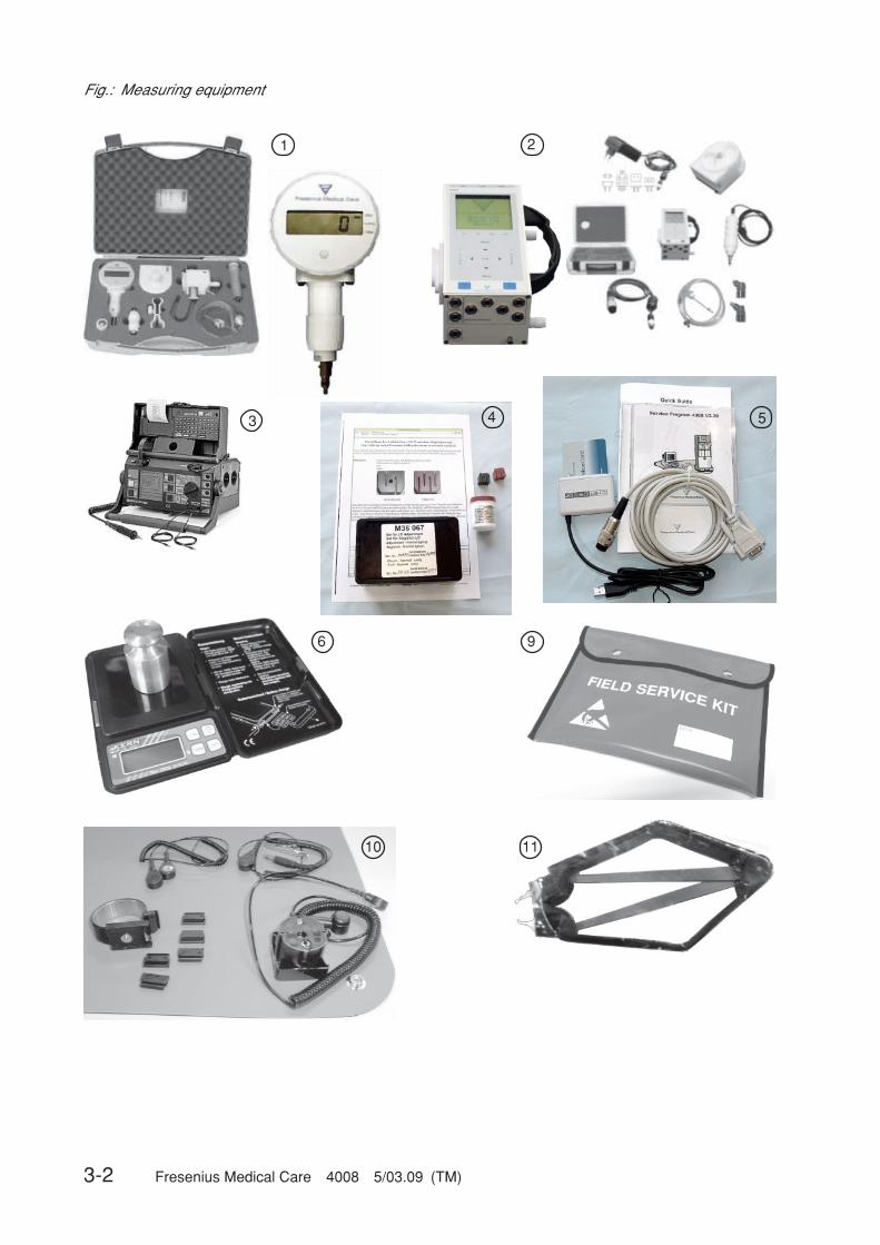
3-2 Fresenius Medical Care 4008 5/03.09 (TM)
Fig.: Measuring equipment
1 2
543
6 9
10 11
Fresenius Medical Care 4008 5/03.09 (TM) 3-3
Pos. Measuring equipment
1 Pressure gauge HMEDwith carrying case (set)
2 Universal measuring device UMED (set)(conductivity, pressure, temperature)
3 Secutest VDE tester (without printer module)Printer module (not ill.)Carrying case (not ill.)
4 Calibration kit for 22 mm AD
5 4008 Service Software set
6 Electronic pocket scalesTest weight with spirit level and certificate
7 Measuring cylinder, 100 ml (not ill.)
8 Special tool for installation and removal of modules (not ill.)
9 ESD service kit
10 ESD work station kit
11 IC extraction tool
The current list of the measuring equipment with part numbers can be found in the electronicSpare Pars Catalog.

3-4 Fresenius Medical Care 4008 5/03.09 (TM)
Fig.: Flow diagram hydraulics incl. DIASAFE®plus (Option) with basic hydraulics

Fresenius Medical Care 4008 5/03.09 (TM) 3-5
86 Recirculation valve87 Drain valve88 Multifunction block88a Degassing chamber88b Secondary air separator88c Primary air separator89 Degassing orifice90a Rinse chamber concentrate90b Rinse chamber bicarbonate91 Rinse valve92 Vent valve94 Concentrate suction tube95 Bicarbonate suction tube97 Air separation pump99 Rinse valve100 Rinse valve102 Central concentrate delivery valve104 Central bicarbonate delivery valve109 Temperature sensor111 Hydrophobic filter112 Vent valve114 Dialysate filter115 Sensor disinfection valve116 Sampling valve117 Check valve (concentrate)118 Check valve (bicarbonate)119 Filter (concentrate)120 Filter (bicarbonate)121 Central concentrate delivery connector122 Central bicarbonate delivery connector123 Pressure switch for V102124 Pressure switch for V104130 bibag® drain valve131 bibag® block131a bibag® air sep. chamber131b bibag® mixing chamber132 bibag® conductivity cell133 bibag® temperature sensor134 bibag® pressure transducer135 bibag® level sensor136 bibag® connector137 bibag® microswitch 1138 bibag® microswitch 2148 Filter/rinse valve 100149 Filter/rinse valve 99151 Orifice210 Filter (degassing orifice)
Hydraulics measuring points
A Reduced water inlet pressureB Balancing chamber loading pressureC Flow pump pressureD Degassing pump pressure
Legend
2 Temperature sensor3 Temperature sensor5 Float switch6 Level sensor7 Conductivity cell8 Blood leak detector9 Pressure transducer10 Reed contact for concentrate12 Reed contact for bicarbonate21 Flow pump22 UF pump23 Concentrate pump24 Dialyzer valve 124b Dialyzer valve 225 Bicarbonate pump26 Bypass valve29 Degassing pump30 Outlet valve31 Balancing chamber valve 132 Balancing chamber valve 233 Balancing chamber valve 334 Balancing chamber valve 435 Balancing chamber valve 536 Balancing chamber valve 637 Balancing chamber valve 738 Balancing chamber valve 841 Water inlet valve43 Fill valve54 Heater rod61 Pressure reducing valve63 Water inlet filter65 Loading pressure valve66 Heater block66a Water inflow chamber66b Heater rod chamber66c Float chamber68 Balancing chamber71 Filter/concentrate72 Filter/bicarbonate73 Filter/dialysate ext.74 Filter/UF75 External flow indicator76 Filter/fill valve77 Heat exchanger78 Relief valve84 Disinfectant valve85 Disinfectant connector
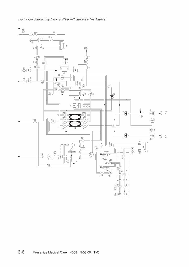
3-6 Fresenius Medical Care 4008 5/03.09 (TM)
Fig.: Flow diagram hydraulics 4008 with advanced hydraulics

Fresenius Medical Care 4008 5/03.09 (TM) 3-7
Legend
2 Temperature sensor3 Temperature sensor4 Temperature sensor (OCM option)5 Float switch6 Level sensor7 Conductivity cell8 Blood leak detector9 Pressure transducer10 Reed contact for concentrate12 Reed contact for bicarbonate21 Flow pump22 UF pump23 Concentrate pump24 Dialyzer valve 124b Dialyzer valve 225 Bicarbonate pump26 Bypass valve29 Degassing pump30 Outlet valve31 Balancing chamber valve 132 Balancing chamber valve 233 Balancing chamber valve 334 Balancing chamber valve 435 Balancing chamber valve 536 Balancing chamber valve 637 Balancing chamber valve 738 Balancing chamber valve 839 Negative pressure valve41 Water inlet valve43 Fill valve54 Heater rod61 Pressure reducing valve63 Water inlet filter65 Loading pressure valve66 Heater block66a Water inflow chamber66b Heater rod chamber66c Float chamber68 Balancing chamber71 Filter/concentrate72 Filter/bicarbonate73 Filter dialysate external74 Filter/UF75 External flow indicator76 Filter/fill valve77 Heat exchanger78 Relief valve84 Disinfectant valve85 Disinfectant connector86 Recirculation valve87 Drain valve88 Multifunction block88a Degassing chamber88b Secondary air separator88c Primary air separator89 Degassing orifice90a Rinse chamber, concentrate90b Rinse chamber, bicarbonate91 Rinse valve
92 Vent valve94 Concentrate suction tube95 Bicarbonate suction tube97 Air separation pump99 Rinse valve100 Rinse valve102 Central concentrate delivery valve104 Central bicarbonate delivery valve109 Temperature sensor110 Condctivity measuring cell (OCM option)111 Hydrophobic filter (advanced hydraulics)112 Vent valve (advanced hydraulics)114 Dialysate filter (Diasafe plus option)115 Sensor disinfection valve116 Sampling valve117 Check valve (concentrate)118 Check valve (bicarbonate)119 Filter (concentrate)120 Filter (bicarbonate)121 Central concentrate delivery connector122 Central bicarbonate delivery connector123 Pressure switch for V102124 Pressure switch for V104125 Temperature compensation plate130 bibag® drain valve132 bibag® conductivity measuring cell133 bibag® temperature sensor134 bibag® pressure transducer136 bibag® connector137 bibag® microswitch 1138 bibag® microswitch 2148 Filter/rinse valve 100149 Filter/rinse valve 99151 Orifice182 Pressure transducer 2 (advanced hydraulics)183 Test valve (advanced hydraulics)184 Test valve filter185 Compressor (advanced hydraulics)188 Evacuation valve189 Retentate valve190 Online filter (Online plus option)191 Online 3 valve (Online plus option)192 Online 2 valve (Online plus option)193 Online 1 valve (Online plus option)194 Rinse port (Online plus option)195 Substituate port (Online plus option)201 Air separator202 Level sensor203 Air separator204 Level sensor205 Concentrate / bicarbonate mixing point210 Filter (degassing orifice)
Hydraulics measuring pointsA Reduced water inlet pressureB Balancing chamber loading pressureC Flow pump pressureD Degassing pump pressure

3-8 Fresenius Medical Care 4008 5/03.09 (TM)
Fig.: P.C.B. overview
LP 630 MotherboardLP 631 CPU 1 (operating system)LP 632 CPU 2 (safety system)LP 633 Input boardLP 634 Output boardLP 635 Display boardLP 636 External connectorsLP 649 Display board 4008 BLP 763 Interface boardLP 924 Display board 4008 HLP 922 Display board 4008 S
P3
LP 632
LP 631
LP 633 LP 634
LP 636
Display board 4008/E: LP 635; 4008H: LP 924; 4008B: LP 649; 4008S: LP 922
Front Panel / Mounting Plate
LP 630
Alpha-Display (4008E/4008B)
P1
DIP-SW1
1
8
8
1
DIP-SW2
8
1
DIP-SW2
8
1
DIP-SW1
Frontplatte / Montageplatte
Rear Panel Rückplatte
Current IncreasingStromerhöhung
(LP 763)TMP-Steilheit
TMP-Gain
SW1
SW2
SH1
SH2
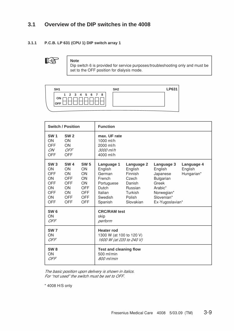
Fresenius Medical Care 4008 5/03.09 (TM) 3-9
3.1 Overview of the DIP switches in the 4008
3.1.1 P.C.B. LP 631 (CPU 1) DIP switch array 1
SH2
1 2 3 4 5 6 7 8ON
OFF
SH1 LP631
☞ NoteDip switch 6 is provided for service purposes/troubleshooting only and must beset to the OFF position for dialysis mode.
Switch / Position Function
SW 1 SW 2 max. UF rateON ON 1000 ml/hOFF ON 2000 ml/hON OFF 3000 ml/hOFF OFF 4000 ml/h
SW 3 SW 4 SW 5 Language 1 Language 2 Language 3 Language 4ON ON ON English English English EnglishOFF ON ON German Finnish Japanese Hungarian*ON OFF ON French Czech BulgarianOFF OFF ON Portuguese Danish GreekON ON OFF Dutch Russian Arabic*OFF ON OFF Italian Turkish Norwegian*ON OFF OFF Swedish Polish Slovenian*OFF OFF OFF Spanish Slovakian Ex-Yugoslavian*
SW 6 CRC/RAM testON skipOFF perform
SW 7 Heater rodON 1300 W (at 100 to 120 V)OFF 1600 W (at 220 to 240 V)
SW 8 Test and cleaning flowON 500 ml/minOFF 800 ml/min
The basic position upon delivery is shown in italics.For “not used” the switch must be set to OFF.
* 4008 H/S only
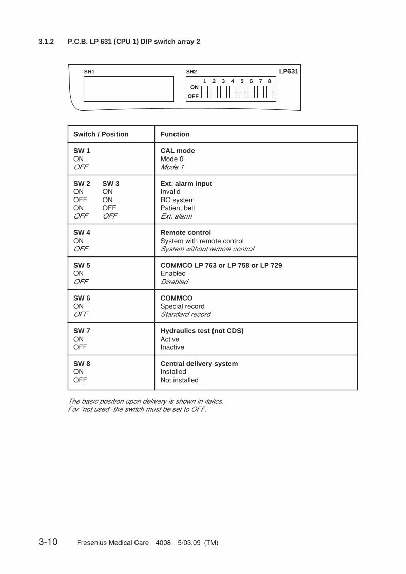
3-10 Fresenius Medical Care 4008 5/03.09 (TM)
3.1.2 P.C.B. LP 631 (CPU 1) DIP switch array 2
1 2 3 4 5 6 7 8ON
OFF
SH2SH1 LP631
Switch / Position Function
SW 1 CAL modeON Mode 0OFF Mode 1
SW 2 SW 3 Ext. alarm inputON ON InvalidOFF ON RO systemON OFF Patient bellOFF OFF Ext. alarm
SW 4 Remote controlON System with remote controlOFF System without remote control
SW 5 COMMCO LP 763 or LP 758 or LP 729ON EnabledOFF Disabled
SW 6 COMMCOON Special recordOFF Standard record
SW 7 Hydraulics test (not CDS)ON ActiveOFF Inactive
SW 8 Central delivery systemON InstalledOFF Not installed
The basic position upon delivery is shown in italics.For “not used” the switch must be set to OFF.
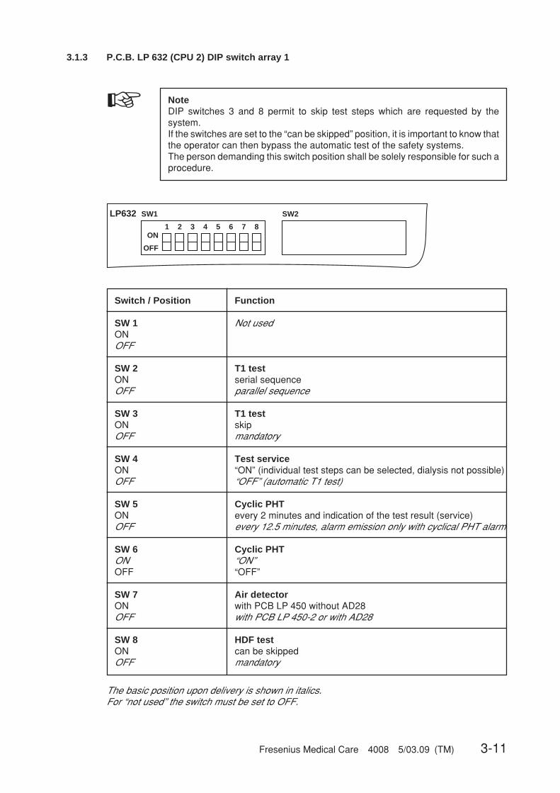
Fresenius Medical Care 4008 5/03.09 (TM) 3-11
3.1.3 P.C.B. LP 632 (CPU 2) DIP switch array 1
☞ NoteDIP switches 3 and 8 permit to skip test steps which are requested by thesystem.If the switches are set to the “can be skipped” position, it is important to know thatthe operator can then bypass the automatic test of the safety systems.The person demanding this switch position shall be solely responsible for such aprocedure.
1 2 3 4 5 6 7 8ON
OFF
SW2SW1LP632
Switch / Position Function
SW 1 Not usedONOFF
SW 2 T1 testON serial sequenceOFF parallel sequence
SW 3 T1 testON skipOFF mandatory
SW 4 Test serviceON “ON” (individual test steps can be selected, dialysis not possible)OFF “OFF” (automatic T1 test)
SW 5 Cyclic PHTON every 2 minutes and indication of the test result (service)OFF every 12.5 minutes, alarm emission only with cyclical PHT alarm
SW 6 Cyclic PHTON “ON”OFF “OFF”
SW 7 Air detectorON with PCB LP 450 without AD28OFF with PCB LP 450-2 or with AD28
SW 8 HDF testON can be skippedOFF mandatory
The basic position upon delivery is shown in italics.For “not used” the switch must be set to OFF.

3-12 Fresenius Medical Care 4008 5/03.09 (TM)
3.1.3 P.C.B. LP 632 (CPU 2) DIP switch array 2
1 2 3 4 5 6 7 8ON
OFF
SW2SW1LP632
Switch / Position Function
SW 1 DIASAFE / DIASAFE®plusplusplusplusplusON OnOFF Off
SW 2 ON-LINE-HDFON OnOFF Off
SW 3 ONLINEplusplusplusplusplus™ON OnOFF Off
SW 4 HydraulicsON with WTROFF withoutWTR
SW 5 V39 TestON OnOFF Off
SW 6 Fast heating HDISON deactivatedOFF activated
SW 7 Not usedONOFF
SW 8 Not usedONOFF
The basic position upon delivery is shown in italics.For “not used” the switch must be set to OFF.

Fresenius Medical Care 4008 5/03.09 (TM) 3-13
3.2 Calibration mode
– The hemodialysis system must beswitched off.
– The service switch must be in the ON(up) position.
– Turn the hemodialysis system on.
3.2.1 Basic conditions
CautionIf the Service switch is set to ON during the treatment or the cleaning program,the heater relay will be turned off.
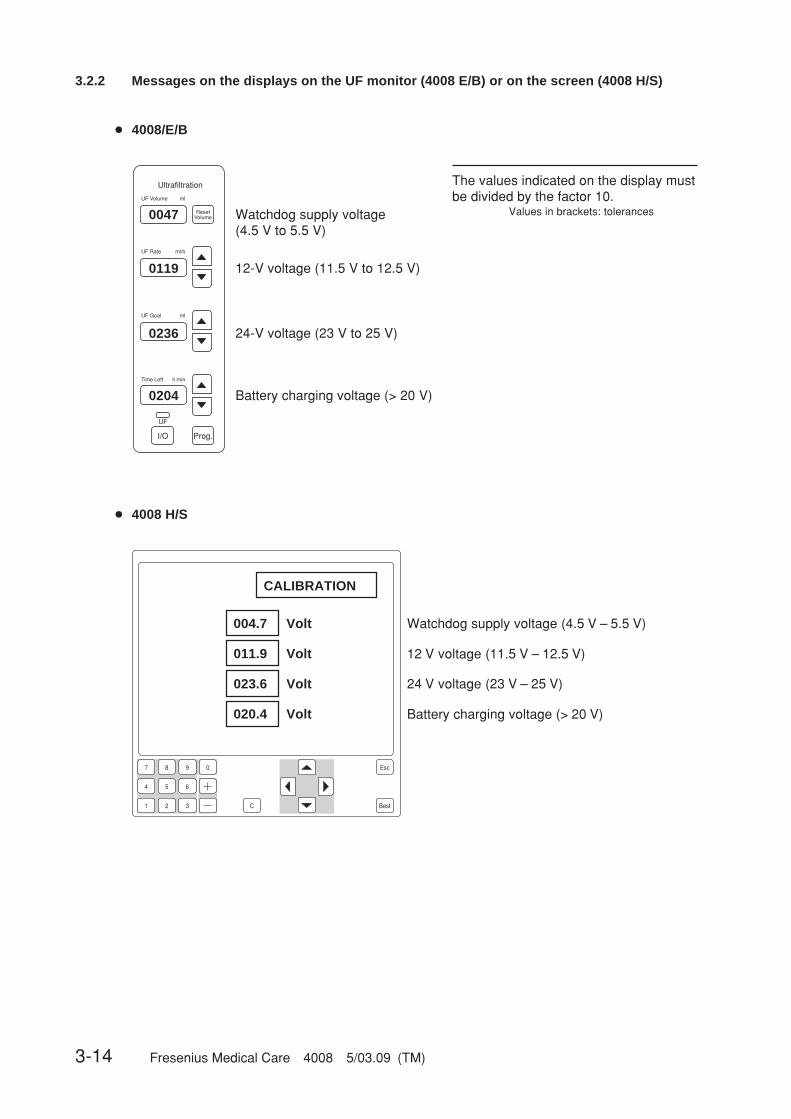
3-14 Fresenius Medical Care 4008 5/03.09 (TM)
Ultrafiltration
ResetVolume
UF
Prog.I/O
UF Volume ml
UF Rate ml/h
UF Goal ml
Time Left h:min
3.2.2 Messages on the displays on the UF monitor (4008 E/B) or on the screen (4008 H/S)
The values indicated on the display mustbe divided by the factor 10.
Values in brackets: tolerances
0119
0047
0204
0236
12-V voltage (11.5 V to 12.5 V)
Watchdog supply voltage(4.5 V to 5.5 V)
Battery charging voltage (> 20 V)
24-V voltage (23 V to 25 V)
CALIBRATION
004.7 Volt
011.9 Volt
023.6 Volt
020.4 Volt
12 V voltage (11.5 V – 12.5 V)
Watchdog supply voltage (4.5 V – 5.5 V)
Battery charging voltage (> 20 V)
24 V voltage (23 V – 25 V)
● 4008/E/B
● 4008 H/S
7 8 9 0
4
1
5 6
2 3 C Best
Esc
Fresenius Medical Care 4008 5/03.09 (TM) 3-15
3.3 Hydraulics
☞ NoteMeasuring equipment for measurement points in the hydraulic unit:UMED, HMED or pressure gauge with a measuring range of–1 to +2.2 bar, min. quality class 1.6.
3-16 Fresenius Medical Care 4008 5/03.09 (TM)
3.3.1 Reduced water inlet pressure
Measuring equipment: UMED, HMED or pressure gauge
Place of measurement: Hydraulics, measurement port A
Condition: Flow on
Check/adjustment:
– Checking the reduced water inlet pressureConnect the measuring equipment to measurement port A.Measure the water pressure with MV 41 closed.Rated value of water inlet pressure: 0.90 to 1.40 barIf it deviates from the rated value, the water inlet pressure must be adjusted.
– Adjusting the reduced water inlet pressurePull back the knurled nut on the pressure reducing valve (16).Turn the knurled nut to set the water pressure to the desired value (clockwise: +, counter-clockwise: –).Push the knurled nut back in.
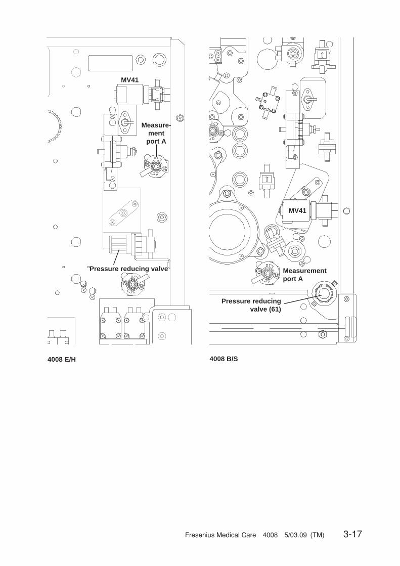
Fresenius Medical Care 4008 5/03.09 (TM) 3-17
MV41
4008 E/H 4008 B/S
Pressure reducingvalve (61)
Measurementport A
Pressure reducing valve
Measure-ment
port A
MV41

3-18 Fresenius Medical Care 4008 5/03.09 (TM)
☞
3.3.2 Degassing pump pressure
Measuring equipment: UMED, HMED or pressure gauge
Place of measurement: Hydraulics, measurement port D
Check/adjustment:– Checking the pressure of the degassing pump
Connect the measuring equipment to the measurement port D.Measure the pressure of the degassing pump.Rated value of degassing pump pressure: –0.81 to –0.85 barIf it deviates from the rated value, the pressure of the degassing pump must be adjusted.
– Adjusting the pressure of the degassing pumpEnter the CALIBRATION menu, select and start the option CAL. DEGAS. PRESSURE(➜ Calibration, chapter 4, section 7).
NoteIf the pressure of the degassing pump was changed, make sure to check theloading pressure and readjust, if necessary.
● Calibration of the negative degassing pressure on higher situated installation sites
If 4008 systems are operated on higher situated sites (observe sea level), the specified negativedegassing pressure can not be reached. The calibration has to be performed as follows:The setting for the degassing pump has to be increased in increments from a low speed until nosignificant increase of the negative pressure can be detected anymore.This setting can also be stored.
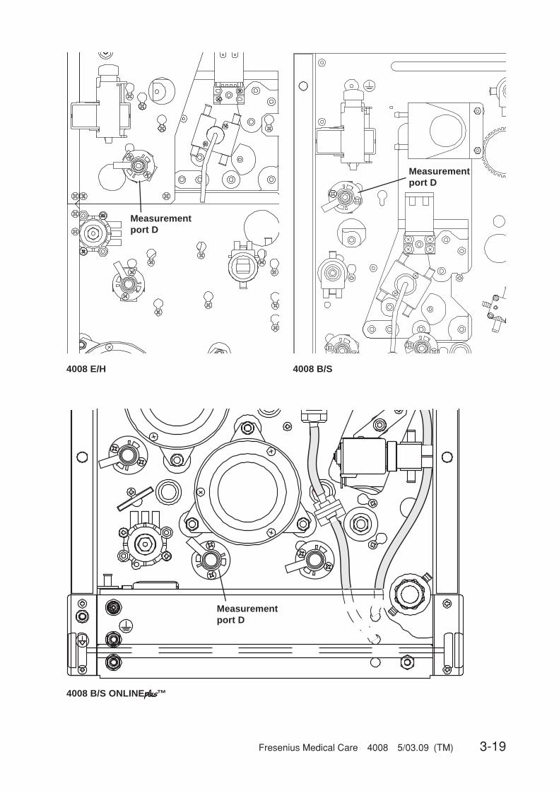
Fresenius Medical Care 4008 5/03.09 (TM) 3-19
Measurementport D
Measurementport D
4008 E/H 4008 B/S
104
117
118
91
100
102
4008 B/S ONLINEplusplusplusplusplus™
Measurementport D

3-20 Fresenius Medical Care 4008 5/03.09 (TM)
☞
3.3.3 Balancing chamber loading pressure
Measuring equipment: UMED, HMED or pressure gauge
Place of measurement: Hydraulics, measurement port B
Check/adjustment:– Checking the loading pressure of the balancing chamber
Connect the measuring equipment to the measurement port B.Measure the loading pressure of the balancing chamber.Rated value of the balancing chamber loading pressure: 1.2 to 1.3 barWith 4008 B EC495, 4008 H EC 295, 4008 S EC 275 or higher (change of the compressionspring in the loading pressure valve): The loading pressure of the balancing chamber hasbeen increased to 1.45 bar ± 0.05 bar.If it deviates from the rated value, the loading pressure of the balancing chamber must beadjusted.
– Adjusting the loading pressure of the balancing chamberUse the loading pressure valve (65) to adjust the loading pressure to the rated value.Turning the adjusting screw clockwise will increase the loading pressure.
NoteDuring the balancing chamber fill phase, the loading pressure drops to approx.1.0 bar.
☞ NoteIf the loading pressure was changed, make sure to check the degassing pumppressure and readjust, if necessary.
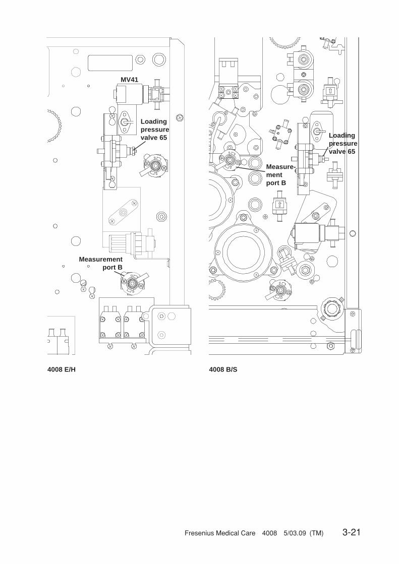
Fresenius Medical Care 4008 5/03.09 (TM) 3-21
MV41
Measure-mentport B
Loadingpressurevalve 65
4008 E/H 4008 B/S
Loadingpressurevalve 65
Measurementport B
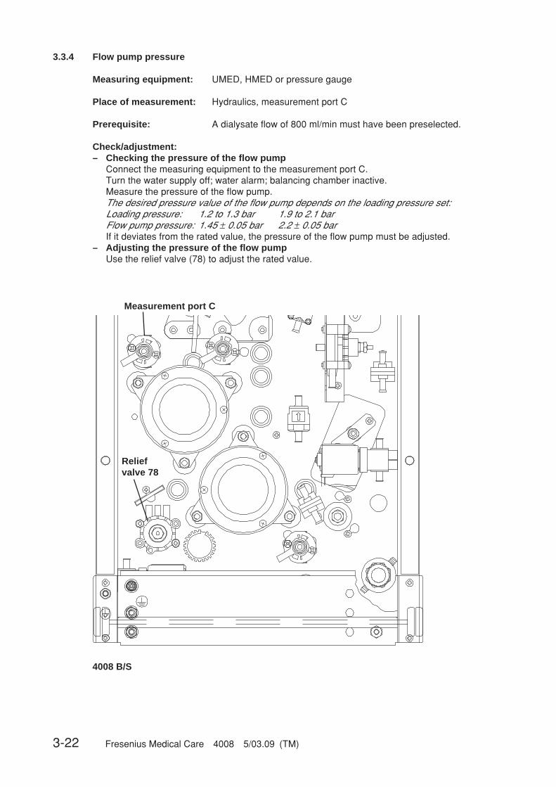
3-22 Fresenius Medical Care 4008 5/03.09 (TM)
Measurement port C
4008 B/S
Reliefvalve 78
3.3.4 Flow pump pressure
Measuring equipment: UMED, HMED or pressure gauge
Place of measurement: Hydraulics, measurement port C
Prerequisite: A dialysate flow of 800 ml/min must have been preselected.
Check/adjustment:– Checking the pressure of the flow pump
Connect the measuring equipment to the measurement port C.Turn the water supply off; water alarm; balancing chamber inactive.Measure the pressure of the flow pump.The desired pressure value of the flow pump depends on the loading pressure set:Loading pressure: 1.2 to 1.3 bar 1.9 to 2.1 barFlow pump pressure: 1.45 ± 0.05 bar 2.2 ± 0.05 barIf it deviates from the rated value, the pressure of the flow pump must be adjusted.
– Adjusting the pressure of the flow pumpUse the relief valve (78) to adjust the rated value.
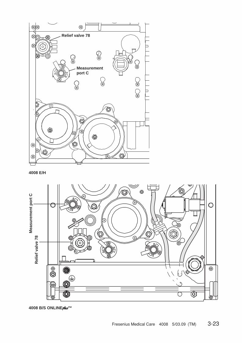
Fresenius Medical Care 4008 5/03.09 (TM) 3-23
4008 E/H
104
117
118
91
100
102
4008 B/S ONLINEplusplusplusplusplus™
Measurementport C
Relief valve 78M
easu
rem
ent
po
rt C
Rel
ief
valv
e 78
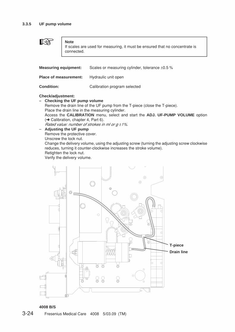
3-24 Fresenius Medical Care 4008 5/03.09 (TM)
T-piece
Drain line
4008 B/S
3.3.5 UF pump volume
☞ NoteIf scales are used for measuring, it must be ensured that no concentrate isconnected.
Measuring equipment: Scales or measuring cylinder, tolerance ±0.5 %
Place of measurement: Hydraulic unit open
Condition: Calibration program selected
Check/adjustment:– Checking the UF pump volume
Remove the drain line of the UF pump from the T-piece (close the T-piece).Place the drain line in the measuring cylinder.Access the CALIBRATION menu, select and start the ADJ. UF-PUMP VOLUME option(➜ Calibration, chapter 4, Part 6).Rated value: number of strokes in ml or g ±1%.
– Adjusting the UF pumpRemove the protective cover.Unscrew the lock nut.Change the delivery volume, using the adjusting screw (turning the adjusting screw clockwisereduces, turning it counter-clockwise increases the stroke volume).Retighten the lock nut.Verify the delivery volume.

Fresenius Medical Care 4008 5/03.09 (TM) 3-25
T-piece
4008 E/H
Drain line
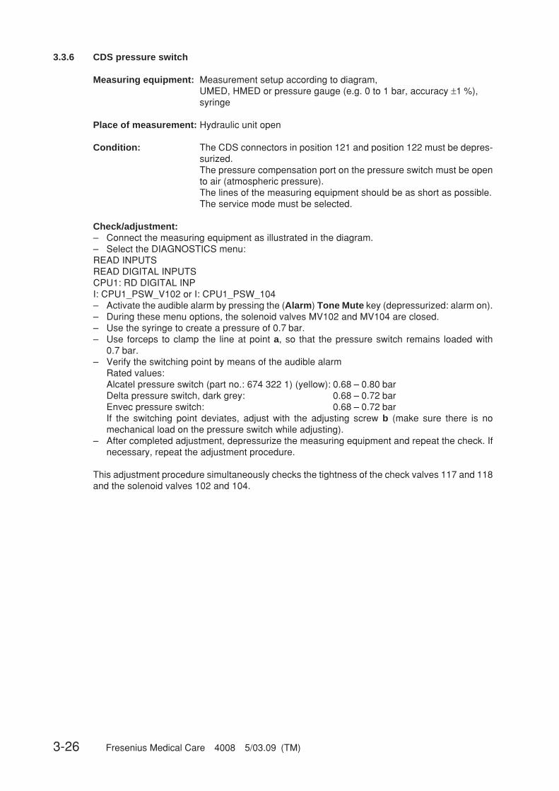
3-26 Fresenius Medical Care 4008 5/03.09 (TM)
3.3.6 CDS pressure switch
Measuring equipment: Measurement setup according to diagram,UMED, HMED or pressure gauge (e.g. 0 to 1 bar, accuracy ±1 %),syringe
Place of measurement: Hydraulic unit open
Condition: The CDS connectors in position 121 and position 122 must be depres-surized.The pressure compensation port on the pressure switch must be opento air (atmospheric pressure).The lines of the measuring equipment should be as short as possible.The service mode must be selected.
Check/adjustment:– Connect the measuring equipment as illustrated in the diagram.– Select the DIAGNOSTICS menu:READ INPUTSREAD DIGITAL INPUTSCPU1: RD DIGITAL INPI: CPU1_PSW_V102 or I: CPU1_PSW_104– Activate the audible alarm by pressing the (Alarm) Tone Mute key (depressurized: alarm on).– During these menu options, the solenoid valves MV102 and MV104 are closed.– Use the syringe to create a pressure of 0.7 bar.– Use forceps to clamp the line at point a, so that the pressure switch remains loaded with
0.7 bar.– Verify the switching point by means of the audible alarm
Rated values:Alcatel pressure switch (part no.: 674 322 1) (yellow): 0.68 – 0.80 barDelta pressure switch, dark grey: 0.68 – 0.72 barEnvec pressure switch: 0.68 – 0.72 barIf the switching point deviates, adjust with the adjusting screw b (make sure there is nomechanical load on the pressure switch while adjusting).
– After completed adjustment, depressurize the measuring equipment and repeat the check. Ifnecessary, repeat the adjustment procedure.
This adjustment procedure simultaneously checks the tightness of the check valves 117 and 118and the solenoid valves 102 and 104.
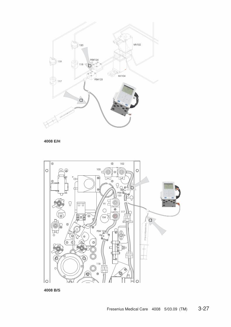
Fresenius Medical Care 4008 5/03.09 (TM) 3-27
4008 B/S
4008 E/H
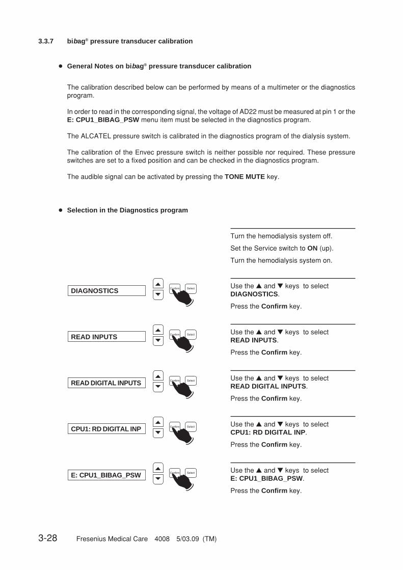
3-28 Fresenius Medical Care 4008 5/03.09 (TM)
3.3.7 bibag® pressure transducer calibration
Use the ▲ and ▼ keys to selectDIAGNOSTICS.
Press the Confirm key.
Confirm SelectDIAGNOSTICS ☛
● General Notes on bibag® pressure transducer calibration
The calibration described below can be performed by means of a multimeter or the diagnosticsprogram.
In order to read in the corresponding signal, the voltage of AD22 must be measured at pin 1 or theE: CPU1_BIBAG_PSW menu item must be selected in the diagnostics program.
The ALCATEL pressure switch is calibrated in the diagnostics program of the dialysis system.
The calibration of the Envec pressure switch is neither possible nor required. These pressureswitches are set to a fixed position and can be checked in the diagnostics program.
The audible signal can be activated by pressing the TONE MUTE key.
● Selection in the Diagnostics program
Turn the hemodialysis system off.
Set the Service switch to ON (up).
Turn the hemodialysis system on.
Use the ▲ and ▼ keys to selectREAD INPUTS.
Press the Confirm key.
Confirm SelectREAD INPUTS ☛
Use the ▲ and ▼ keys to selectREAD DIGITAL INPUTS.
Press the Confirm key.
Confirm SelectREAD DIGITAL INPUTS ☛
Use the ▲ and ▼ keys to selectCPU1: RD DIGITAL INP.
Press the Confirm key.
Confirm SelectCPU1: RD DIGITAL INP ☛
Use the ▲ and ▼ keys to selectE: CPU1_BIBAG_PSW.
Press the Confirm key.
Confirm SelectE: CPU1_BIBAG_PSW ☛
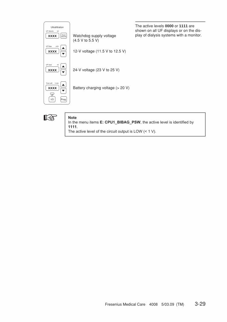
Fresenius Medical Care 4008 5/03.09 (TM) 3-29
The active levels 0000 or 1111 areshown on all UF displays or on the dis-play of dialysis systems with a monitor.
Ultrafiltration
ResetVolume
UF
Prog.I/O
UF Volume ml
UF Rate ml/h
UF Goal ml
Time Left h:min
xxxx
xxxx
xxxx
xxxx
☞ Note
In the menu items E: CPU1_BIBAG_PSW, the active level is identified by
1111.
The active level of the circuit output is LOW (< 1 V).
12-V voltage (11.5 V to 12.5 V)
Watchdog supply voltage(4.5 V to 5.5 V)
Battery charging voltage (> 20 V)
24-V voltage (23 V to 25 V)

3-30 Fresenius Medical Care 4008 5/03.09 (TM)
● Calibration of the ALCATEL pressure switch
Clamp the lines (X).
Connect the pressure gauge and the sy-ringe and build up a pressure of100 mbar + 10 mbar.
Turn the potentiometer (AD22 or directlyon the pressure switch) until Low Level(< 1 V) (1111) is displayed on the UFdisplays.
Slowly turn the potentiometer into theopposite direction until the High level(> 10 V) (0000) is shown on the UF dis-plays.
B
134
137138
136
2
104
100
9012
91
148
95
b
XX
No pressure at the pressure transducer.
UF displays must show High level(0000).
Clamp the lines (X).
Connect the pressure gauge and the sy-ringe and build up a pressure of160 mbar.
UF displays must show Low level (1111).
Slowly reduce the pressure. UF displaysmust show High level (0000) at a mini-mum of 100 mbar.
If necessary, repeat calibration.
B
134
137138
136
2
104
100
9012
91
148
95
b
XX
Pressure transducer calibrationcompleted.
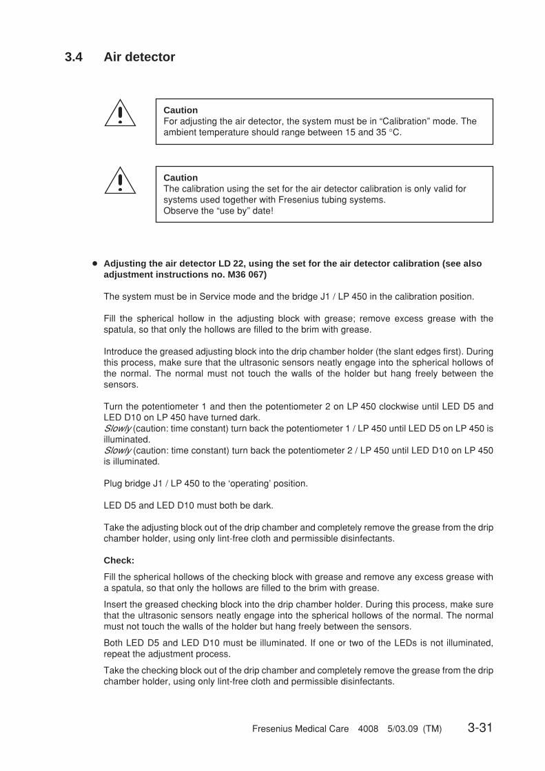
Fresenius Medical Care 4008 5/03.09 (TM) 3-31
3.4 Air detector
CautionFor adjusting the air detector, the system must be in “Calibration” mode. Theambient temperature should range between 15 and 35 °C.
● Adjusting the air detector LD 22, using the set for the air detector calibration (see alsoadjustment instructions no. M36 067)
The system must be in Service mode and the bridge J1 / LP 450 in the calibration position.
Fill the spherical hollow in the adjusting block with grease; remove excess grease with thespatula, so that only the hollows are filled to the brim with grease.
Introduce the greased adjusting block into the drip chamber holder (the slant edges first). Duringthis process, make sure that the ultrasonic sensors neatly engage into the spherical hollows ofthe normal. The normal must not touch the walls of the holder but hang freely between thesensors.
Turn the potentiometer 1 and then the potentiometer 2 on LP 450 clockwise until LED D5 andLED D10 on LP 450 have turned dark.Slowly (caution: time constant) turn back the potentiometer 1 / LP 450 until LED D5 on LP 450 isilluminated.Slowly (caution: time constant) turn back the potentiometer 2 / LP 450 until LED D10 on LP 450is illuminated.
Plug bridge J1 / LP 450 to the ‘operating’ position.
LED D5 and LED D10 must both be dark.
Take the adjusting block out of the drip chamber and completely remove the grease from the dripchamber holder, using only lint-free cloth and permissible disinfectants.
Check:
Fill the spherical hollows of the checking block with grease and remove any excess grease witha spatula, so that only the hollows are filled to the brim with grease.
Insert the greased checking block into the drip chamber holder. During this process, make surethat the ultrasonic sensors neatly engage into the spherical hollows of the normal. The normalmust not touch the walls of the holder but hang freely between the sensors.
Both LED D5 and LED D10 must be illuminated. If one or two of the LEDs is not illuminated,repeat the adjustment process.
Take the checking block out of the drip chamber and completely remove the grease from the dripchamber holder, using only lint-free cloth and permissible disinfectants.
CautionThe calibration using the set for the air detector calibration is only valid forsystems used together with Fresenius tubing systems.Observe the “use by” date!
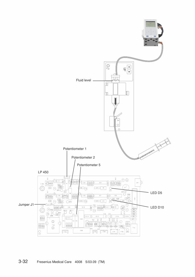
3-32 Fresenius Medical Care 4008 5/03.09 (TM)
Jumper J1LED D10
LED D5
Potentiometer 1
Potentiometer 2
Potentiometer 5
LP 450
Fluid level

Fresenius Medical Care 4008 5/03.09 (TM) 3-33
● Alternative: Adjusting the air detector without the set for the air detector calibration
Measuring equipment: Measurement setup according to diagramUMED, HMED or pressure gauge, bubble catcher, syringe filled withdegassed water or saline solution
Place of measurement: Air detector
Check / adjustment:– Adjusting the ultrasonic detector
Install the measurement set-up before checking / adjusting the air detector. Do not yet placethe line in the occlusion clamp.Jumper J1 / P.C.B. LP 450 set to calibration.Fill the bubble catcher. The fluid level must be set to approx. 10 mm above the top edge of thesensor holder.Turn potentiometer 1 and potentiometer 2 on P.C.B. LP 450 clockwise, until the LED DI5 andLED DI10 on P.C.B. LP 450 are dark.Slowly (attention: time constant) turn potentiometer 1 on P.C.B. LP 450 counterclockwise,until the LED DI5 on P.C.B. LP 450 lights.Slowly (attention: time constant) turn the potentiometer 2 on P.C.B. LP 450 counterclockwise,until the LED DI10 on P.C.B. LP 450 lights.After completion of the calibration procedure, set the jumper J1 / P.C.B. LP 450 back to theoperation position.
– CheckLower the level in the bubble catcher: an alarm must be emitted.Raise the level in the bubble catcher: it must be possible to clear the alarm; both LEDs must beoff!
– Checking the venous line clamp (➜ Fig.)Place the line in the venous line clamp.Open the clamp and, using the syringe, generate a pressure of approx. 2 bar.Close the clamp.The pressure must not drop by more than 0.1 bar within 3 minutes.
– Adjusting the optical detectorUse the gray filter, double-laid, part no. 640 560 1.Diagnostics menu; reading of digital inputs by CPU 1; item E: CPU1_OD_IN.Install the gray filter, double-laid; close the hinged cover.Slowly turn potentiometer P5 on P.C.B. LP 450 clockwise, until the UF display indicates 1111.Slowly turn potentiometer P5 counterclockwise, until the display jumps to 0000. Continue toturn the potentiometer counterclockwise for half a turn.Avoid incident light from external sources.

3-34 Fresenius Medical Care 4008 5/03.09 (TM)
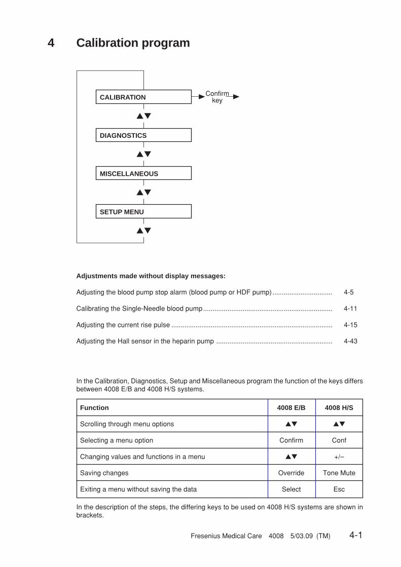
Fresenius Medical Care 4008 5/03.09 (TM) 4-1
▲▼
▲▼
▲▼
▲▼
ConfirmkeyCALIBRATION
DIAGNOSTICS
MISCELLANEOUS
SETUP MENU
4 Calibration program
Adjustments made without display messages:
Adjusting the blood pump stop alarm (blood pump or HDF pump)................................ 4-5
Calibrating the Single-Needle blood pump..................................................................... 4-11
Adjusting the current rise pulse ...................................................................................... 4-15
Adjusting the Hall sensor in the heparin pump .............................................................. 4-43
In the Calibration, Diagnostics, Setup and Miscellaneous program the function of the keys differsbetween 4008 E/B and 4008 H/S systems.
Function 4008 E/B 4008 H/S
Scrolling through menu options ▲▼ ▲▼
Selecting a menu option Confirm Conf
Changing values and functions in a menu ▲▼ +/–
Saving changes Override Tone Mute
Exiting a menu without saving the data Select Esc
In the description of the steps, the differing keys to be used on 4008 H/S systems are shown inbrackets.

4-2 Fresenius Medical Care 4008 5/03.09 (TM)
▲▼
▲▼
▲▼
▲▼
▲▼
▲▼
▲▼
▲▼
▲▼
▲▼
▲▼
▲▼
▲▼
▲▼
▲▼
▲▼
▲▼
▲▼
▲▼
Confirmkey
Confirmkey see Part 1
Confirmkey see Part 2
Confirmkey see Part 3
Confirmkey see Part 4
Confirmkey see Part 5
Confirmkey see Part 6
Confirmkey see Part 7
Confirmkey see Part 8
Confirmkey see Part 9
Confirmkey see Part 10
Confirmkey see Part 11
Confirmkey see Part 12
Confirmkey see Part 13
Confirmkey see Part 14
Confirmkey see Part 15
Confirmkey see Part 16
(Option)
Confirmkey see Part 18
Confirmkey
Confirmkey see Part 17
CALIBRATION
CAL. ART. PRESSURE
CAL. ART. P_MODULE
CALIB. (B)-PUMP-RATE
CAL. VENOUS PRESSURE
CAL. VEN. P_MODULE
ADJ. UF-PUMP VOLUME
CAL. DEGAS. PRESSURE
CAL. FLOW 300 ml/min
CAL. FLOW 500 ml/min
CAL. FLOW 800 ml/min
CALIB. TEMPERATURE
CAL. MIXING SYSTEM
CALIB. CONDUCTIVITY
CAL. DIAL. PRESSURE
CALIBRATE BLD
CALIB. BIBAG VALUES
NOVRAM
back to main menu ?
RESET FAILURE RECORD
☞ NoteBefore calibrating the hy-draulics, remove possiblyexisting precipitate by run-ning an appropriate disin-fection program.
● Main menu

Fresenius Medical Care 4008 5/03.09 (TM) 4-3
▲▼
▲▼
▲▼
Confirmkey
Confirmkey
Confirmkey
Confirmkey
Activate various pressurevalues. The values on thedisplay, the art. pressuredisplay and the reference
instrument must be identical.Check whether the scale
limits can be reached.Tolerance: ±10 mmHg
Select(Esc)key
Override(Tone Mute)
key
approx. 3 sec
Set the value of the reference instrument
on the display by pressing the ▲▼ (+/–) keys.
Override(Tone Mute)
key
approx. 3 sec
Note:If calibration of this function is impossible, the “CAL. ART. P_MODULE” mode must first be performed.
Art. pressure transduceropen to atmosphere
Apply ≥210 mmHg to art.pressure transducer
(reference instrument!)
CAL. ART. PRESSURE
Arterial PRESSURE
Art. PRESS. CHECK
back to menu ?
art. press: ±0 mmHg
art.zero.: ±0 mmHg
ACKNOWLEDGED
art.gain.: +210 mmHg
DATA STORED
● Part 1: Calibrating the arterial pressure
NotePressure gauge accuracy: ±1 % of the measured value.

4-4 Fresenius Medical Care 4008 5/03.09 (TM)
Confirmkey
Select(Esc)key
arterial pressure transduceropen to atmosphere (arterial blood pump)
Set the value on the alphanumericdisplay to 000 mmHg by
pressing the ▲▼ keys on the blood pump module
Acknowledge by pressingthe Start/Stop key on the
blood pump module
Connect the syringe, whichis connected to the externalreference instrument, to thearterial pressure transducer.
Apply exactly 250 mmHg tothe pressure transducer
Press the ▲▼ keys on theblood pump module to
readjust the slope, until the alphanumeric display agrees with the external reference
instrument.
Acknowledge by pressing the Start/Stop key on the
blood pump module
Data stored.Should this message fail to appear,
repeat the calibration procedure.
CAL. ART. P_MODULE
art. press: XXX mmHg
● Part 2: Calibrating the pressure in the arterial blood pump
Set the hex switch in the module (P.C.B. LP 624, pos. 1) to position F.Should the error message E02 appear on the blood pump display, clear the message by pressingthe Start/Stop key.
Return the hex switch to position 0.

Fresenius Medical Care 4008 5/03.09 (TM) 4-5
Change the preset value(15/30 sec) by pressing
the ▲▼ keys on the blood pump module.
Acknowledge by pressing the Start/Stop
key on the module.
The stored value appears after 2 seconds.
Return the hex switch to position 0.
Automatic reset on the module
● Without display messages: adjusting the blood pump stop alarm(blood pump or HDF pump)
Set the hex switch in the module (P.C.B. LP 624, pos. 1) to position B.Should the error message E02 appear on the blood pump display, clear the message by pressingthe Start/Stop key.
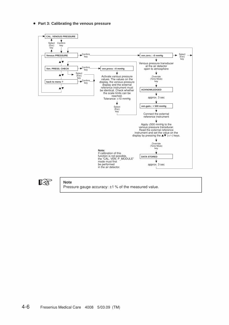
4-6 Fresenius Medical Care 4008 5/03.09 (TM)
▲▼
▲▼
▲▼
Note:If calibration of this function is not possible, the “CAL. VEN. P_MODULE” mode must first be performedin the air detector.
Confirmkey
Confirmkey
Confirmkey
Confirmkey
Activate various pressure values. The values on the
display, the venous pressure display and the external
reference instrument must be identical. Check whether
the scale limits can be reached.
Tolerance: ±10 mmHg
Select(Esc)key
Venous pressure transducerat the air detector
open to atmosphere
Override (Tone Mute)
key
Select (Esc)key
Select(Esc)key
Select(Esc)key
approx. 3 sec
Connect the externalreference instrument
Apply ≤500 mmHg to the venous pressure transducer. Read the external reference
instrument and set the value on the display by pressing the ▲▼ (+/–) keys.
Override (Tone Mute)
key
approx. 3 sec
Venous PRESSURE
Ven. PRESS. CHECK
back to menu ?
CAL. VENOUS PRESSURE
ven.press: ±0 mmHg
ven.zero.: ±0 mmHg
ACKNOWLEDGED
ven.gain.: + 500 mmHg
DATA STORED
● Part 3: Calibrating the venous pressure
☞ NotePressure gauge accuracy: ±1 % of the measured value.

Fresenius Medical Care 4008 5/03.09 (TM) 4-7
Confirmkey
Select (Esc)key
The venous pressure transducer is open to atmosphere (air detector module)
Readjust the zero-point potentiometer (P3/LP450) in
the air detector until the display indicates ±0 mmHg
Connect the syringe, which is connected to the external
reference instrument, to the venous pressure transducer.
Apply ≥400 mmHg to the pressure transducer.
Use the slope potentiometer (P4/LP450) to set the value of
the external reference instrument on the display.
Select (Esc)key
Note:Check zero point and slope;if necessary, repeat the procedure.
Note:When adjusting the air detector, execute the CAL. VENOUS PRESSURE menu item.
CAL. VEN. P_MODULE
ven.press: XXX mmHg
ven.press: ±0 mmHg
● Part 4: Calibrating the venous pressure measurement in the air detector
LP 450
Pot 3 Pot 4
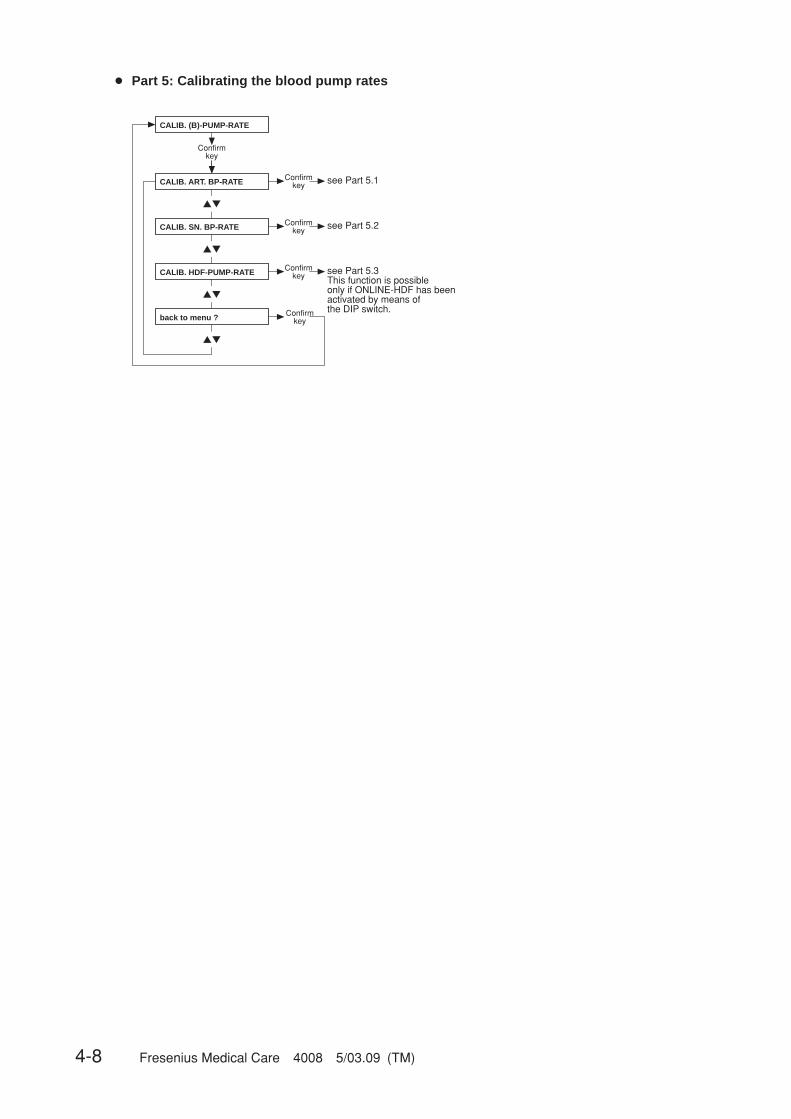
4-8 Fresenius Medical Care 4008 5/03.09 (TM)
▲▼
▲▼
▲▼
▲▼
▲▼
Confirmkey see Part 5.1
Confirmkey see Part 5.3
This function is possible only if ONLINE-HDF has been activated by means of the DIP switch.Confirm
key
Confirmkey
Confirmkey see Part 5.2
CALIB. ART. BP-RATE
CALIB. HDF-PUMP-RATE
back to menu ?
CALIB. (B)-PUMP-RATE
CALIB. SN. BP-RATE
● Part 5: Calibrating the blood pump rates
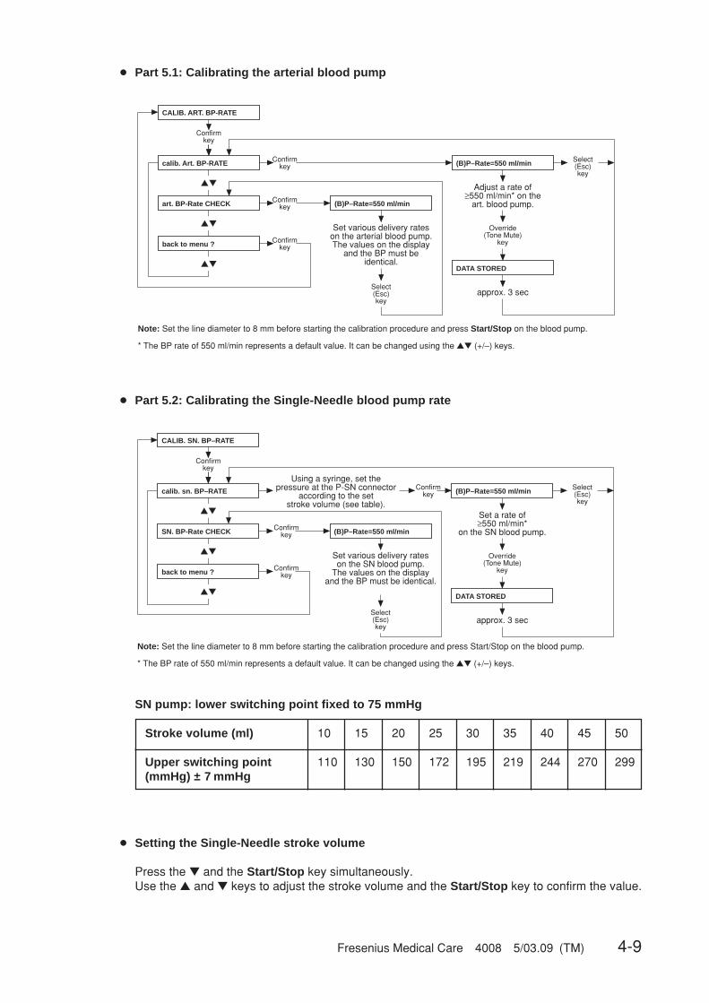
Fresenius Medical Care 4008 5/03.09 (TM) 4-9
▲▼
▲▼
▲▼
Confirm key
Confirm key
Confirm key
Confirm key
Set various delivery rates on the arterial blood pump. The values on the display
and the BP must be identical.
Select(Esc)key
Adjust a rate of≥550 ml/min* on the
art. blood pump.
Override(Tone Mute)
key
approx. 3 sec
Select(Esc)key
Note: Set the line diameter to 8 mm before starting the calibration procedure and press Start/Stop on the blood pump.
* The BP rate of 550 ml/min represents a default value. It can be changed using the ▲▼ (+/–) keys.
calib. Art. BP-RATE
art. BP-Rate CHECK
back to menu ?
CALIB. ART. BP-RATE
(B)P–Rate=550 ml/min
DATA STORED
(B)P–Rate=550 ml/min
▲▼
▲▼
▲▼
Confirmkey
Confirmkey
Confirmkey
Confirmkey
Set various delivery rates on the SN blood pump.
The values on the display and the BP must be identical.
Select(Esc)key
Set a rate of ≥550 ml/min*
on the SN blood pump.
Override(Tone Mute)
key
approx. 3 sec
Select(Esc)key
Using a syringe, set the pressure at the P-SN connector
according to the set stroke volume (see table).
Note: Set the line diameter to 8 mm before starting the calibration procedure and press Start/Stop on the blood pump.
* The BP rate of 550 ml/min represents a default value. It can be changed using the ▲▼ (+/–) keys.
calib. sn. BP–RATE
SN. BP-Rate CHECK
back to menu ?
CALIB. SN. BP–RATE
(B)P–Rate=550 ml/min
DATA STORED
(B)P–Rate=550 ml/min
● Part 5.1: Calibrating the arterial blood pump
● Part 5.2: Calibrating the Single-Needle blood pump rate
SN pump: lower switching point fixed to 75 mmHg
Stroke volume (ml) 10 15 20 25 30 35 40 45 50
Upper switching point 110 130 150 172 195 219 244 270 299(mmHg) ± 7 mmHg
● Setting the Single-Needle stroke volume
Press the ▼ and the Start/Stop key simultaneously.Use the ▲ and ▼ keys to adjust the stroke volume and the Start/Stop key to confirm the value.
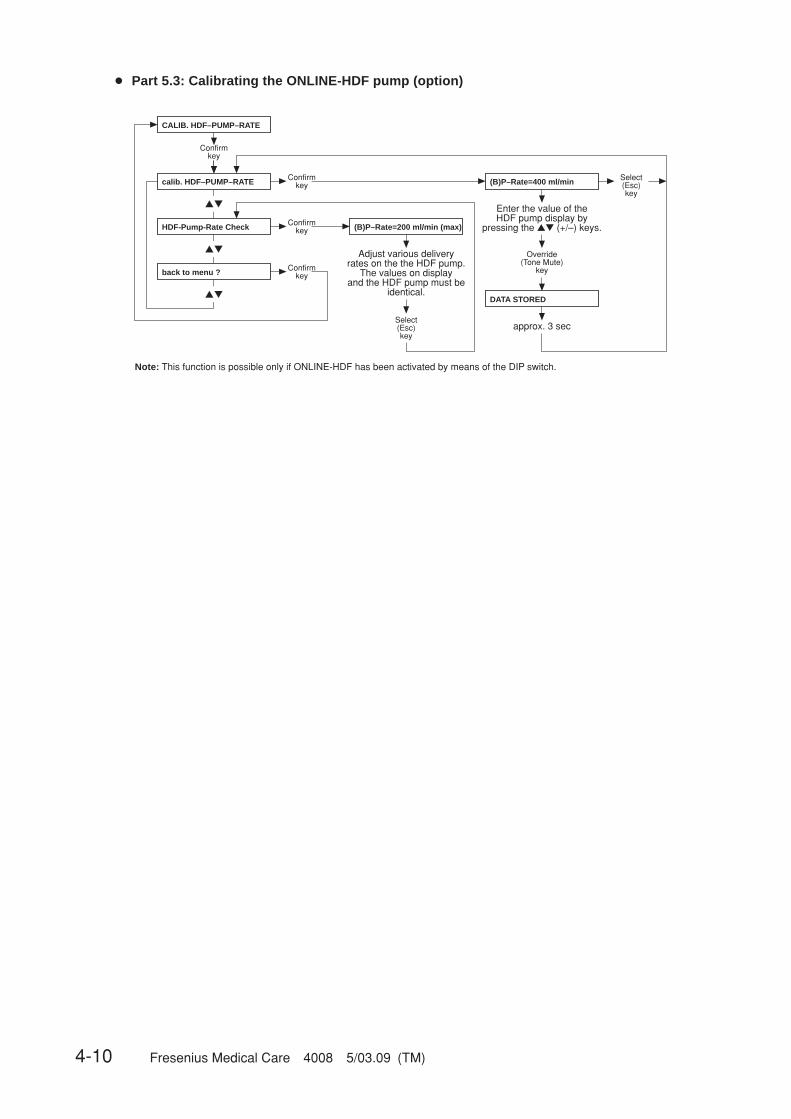
4-10 Fresenius Medical Care 4008 5/03.09 (TM)
▲▼
▲▼
▲▼
Confirmkey
Confirmkey
Confirmkey
Confirmkey
Adjust various delivery rates on the the HDF pump.
The values on display and the HDF pump must be
identical.
Select(Esc)key
Enter the value of the HDF pump display by
pressing the ▲▼ (+/–) keys.
Override(Tone Mute)
key
approx. 3 sec
Select(Esc)key
Note: This function is possible only if ONLINE-HDF has been activated by means of the DIP switch.
calib. HDF–PUMP–RATE
HDF-Pump-Rate Check
back to menu ?
CALIB. HDF–PUMP–RATE
(B)P–Rate=200 ml/min (max)
DATA STORED
(B)P–Rate=400 ml/min
● Part 5.3: Calibrating the ONLINE-HDF pump (option)

Fresenius Medical Care 4008 5/03.09 (TM) 4-11
The SN pressure transducer is open to atmosphere
(SN blood pump).
Press the Start/Stop key on the SN blood pump.
Connect the syringe, which is connected to the external
reference instrument, to the SN pressure transducer.
Apply exactly 250 mmHg to the pressure transducer.
Acknowledge by pressingthe Start/Stop key on the
SN blood pump.
The values are stored.
Check the SN stroke volume.
Set stroke volume,e.g. 30 ml.
Using a syringe and the external reference instrument, check
the lower (fixed to 75 mmHg) and the upper switching point. (Depending on the stroke
volume selected, the upper switching point can be found
in the table).
If the switching points are outside the tolerance range,
repeat the calibration procedure.
Finally return the hex switch
to position 1.Then select
SN.BP-Rate CHECK
● Without display messages: Calibrating the Single-Needle blood pump (SN pressure)(option)
Set the hex switch in the module (P.C.B. LP 624, pos. 1) to position F.Should the error message E02 appear on the blood pump display, clear the message by pressingthe Start/Stop key.
SN pump: lower switching point fixed to 75 mmHg
Stroke volume (ml) 10 15 20 25 30 35 40 45 50
Upper switching point 110 130 150 172 195 219 244 270 299(mmHg) ± 7 mmHg
☞ NoteIt may be necessary to change the Single-Needle stroke volume:Press the ▼ and the Start/Stop key simultaneously.Use the ▲ and ▼ keys to adjust the stroke volume and the Start/Stop key toconfirm the value.

4-12 Fresenius Medical Care 4008 5/03.09 (TM)
▲▼
▲▼
▲▼
Confirmkey
Confirmkey
Confirmkey
Enter the number of strokes by pressing the ▲▼ (+/–) keys.
Override(Tone Mute)
key
approx. 3 sec
Selec(Esc)key
Note: Check the volume.If necessary, readjust the UF pumpand repeat the procedure.(See 3.3.5)
Remove the line from the UF pump, close the T-piece.
Hang the line into a graduated cylinder.
Select(Esc)key
Switch on the UF pump bypressing the UF I/O key.
UF I/Okey
The remaining UF strokes are indicated on the display. The “UF Goal” display
indicates the number of preselected strokes.
Confirmkey
optional
optional
UF–Pump 1 (Vers. I)
UF-Pump 2
back to menu ?
ADJ. UF-PUMP VOLUME
ACKNOWLEDGED
pulse-amount = 60
press uf key
uf pulses left = 60
● Part 6: Adjusting the UF pump volume
☞ NoteGraduated cylinder accuracy: ±0.5 %.
☞ NoteIf a scale is used as measurement instrument it must be ensured that no con-centrate is connected.
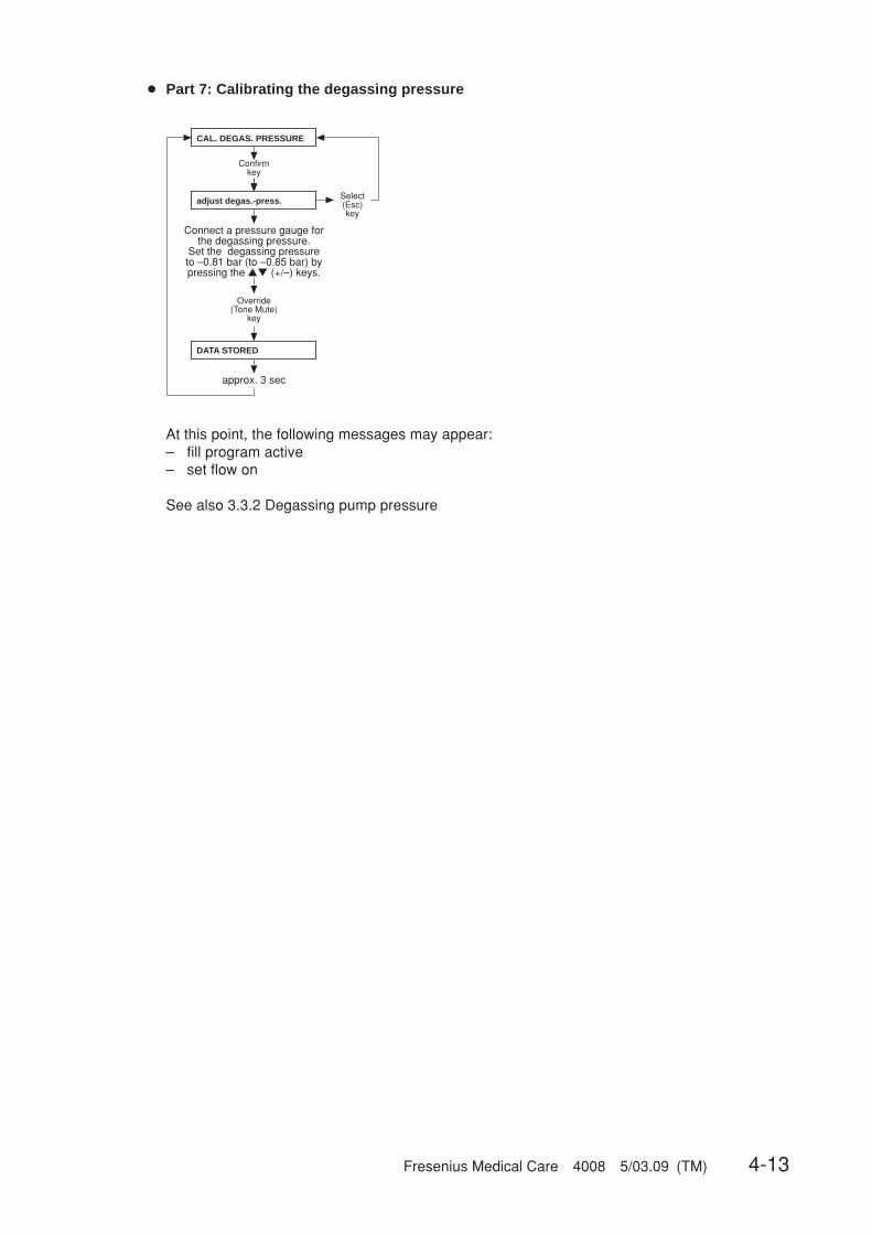
Fresenius Medical Care 4008 5/03.09 (TM) 4-13
Confirmkey
Select(Esc)key
Connect a pressure gauge for the degassing pressure.
Set the degassing pressure to –0.81 bar (to –0.85 bar) by pressing the ▲▼ (+/–) keys.
approx. 3 sec
Override(Tone Mute)
key
CAL. DEGAS. PRESSURE
adjust degas.-press.
DATA STORED
● Part 7: Calibrating the degassing pressure
At this point, the following messages may appear:– fill program active– set flow on
See also 3.3.2 Degassing pump pressure
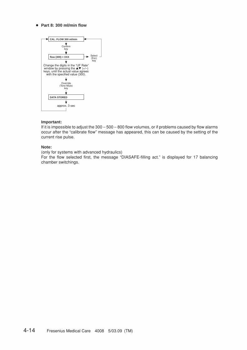
4-14 Fresenius Medical Care 4008 5/03.09 (TM)
Confirmkey
Select(Esc)key
Change the digits in the “UF Rate” window by pressing the ▲▼ (+/–) keys, until the actual value agrees
with the specified value (300).
approx. 3 sec
Override(Tone Mute)
key
CAL. FLOW 300 ml/min
flow (300) = XXX
DATA STORED
Important:If it is impossible to adjust the 300 – 500 – 800 flow volumes, or if problems caused by flow alarmsoccur after the “calibrate flow” message has appeared, this can be caused by the setting of thecurrent rise pulse.
Note:(only for systems with advanced hydraulics)For the flow selected first, the message “DIASAFE-filling act.” is displayed for 17 balancingchamber switchings.
● Part 8: 300 ml/min flow
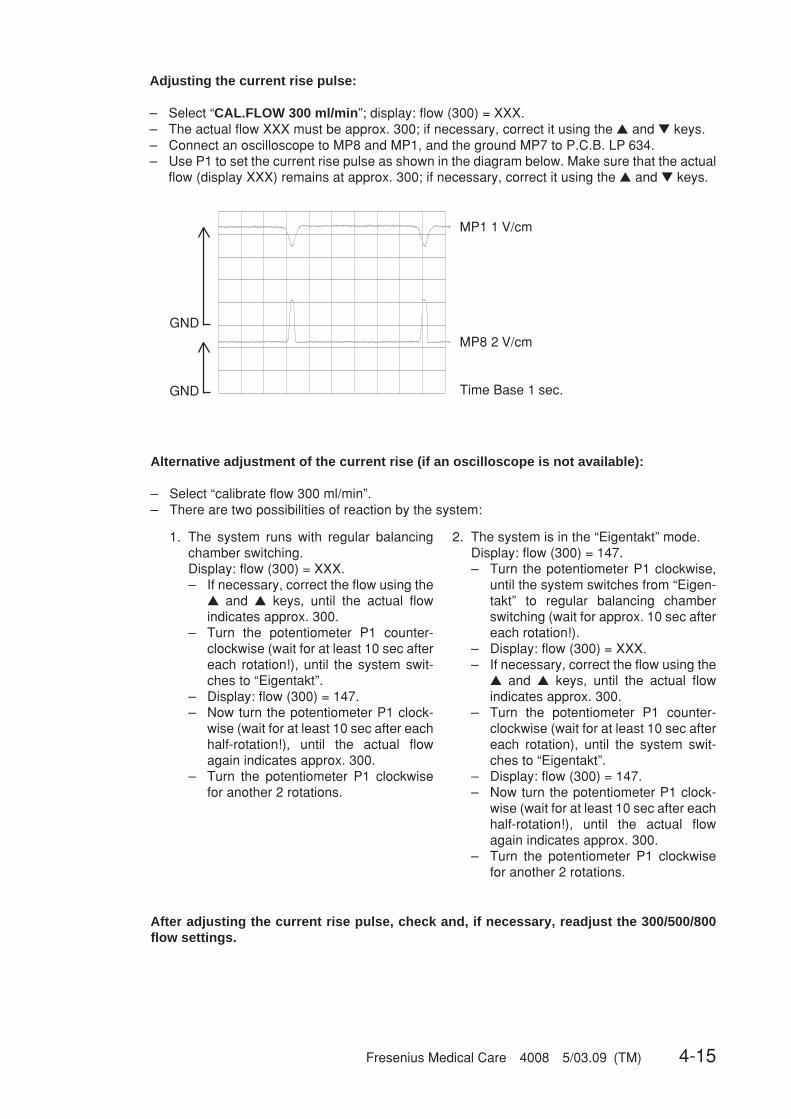
Fresenius Medical Care 4008 5/03.09 (TM) 4-15
Time Base 1 sec.
MP1 1 V/cm
MP8 2 V/cm
GND
GND
Adjusting the current rise pulse:
– Select “CAL.FLOW 300 ml/min”; display: flow (300) = XXX.– The actual flow XXX must be approx. 300; if necessary, correct it using the ▲ and ▼ keys.– Connect an oscilloscope to MP8 and MP1, and the ground MP7 to P.C.B. LP 634.– Use P1 to set the current rise pulse as shown in the diagram below. Make sure that the actual
flow (display XXX) remains at approx. 300; if necessary, correct it using the ▲ and ▼ keys.
Alternative adjustment of the current rise (if an oscilloscope is not available):
– Select “calibrate flow 300 ml/min”.– There are two possibilities of reaction by the system:
After adjusting the current rise pulse, check and, if necessary, readjust the 300/500/800flow settings.
2. The system is in the “Eigentakt” mode.Display: flow (300) = 147.– Turn the potentiometer P1 clockwise,
until the system switches from “Eigen-takt” to regular balancing chamberswitching (wait for approx. 10 sec aftereach rotation!).
– Display: flow (300) = XXX.– If necessary, correct the flow using the
▲ and ▲ keys, until the actual flowindicates approx. 300.
– Turn the potentiometer P1 counter-clockwise (wait for at least 10 sec aftereach rotation), until the system swit-ches to “Eigentakt”.
– Display: flow (300) = 147.– Now turn the potentiometer P1 clock-
wise (wait for at least 10 sec after eachhalf-rotation!), until the actual flowagain indicates approx. 300.
– Turn the potentiometer P1 clockwisefor another 2 rotations.
1. The system runs with regular balancingchamber switching.Display: flow (300) = XXX.– If necessary, correct the flow using the
▲ and ▲ keys, until the actual flowindicates approx. 300.
– Turn the potentiometer P1 counter-clockwise (wait for at least 10 sec aftereach rotation!), until the system swit-ches to “Eigentakt”.
– Display: flow (300) = 147.– Now turn the potentiometer P1 clock-
wise (wait for at least 10 sec after eachhalf-rotation!), until the actual flowagain indicates approx. 300.
– Turn the potentiometer P1 clockwisefor another 2 rotations.
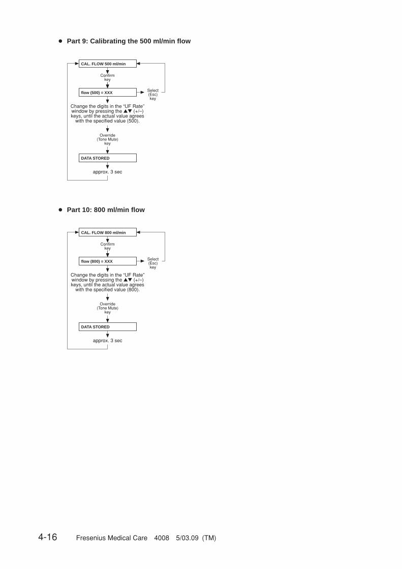
4-16 Fresenius Medical Care 4008 5/03.09 (TM)
Confirmkey
Select(Esc)key
Change the digits in the “UF Rate” window by pressing the ▲▼ (+/–) keys, until the actual value agrees
with the specified value (500).
approx. 3 sec
Override(Tone Mute)
key
CAL. FLOW 500 ml/min
flow (500) = XXX
DATA STORED
Confirmkey
Select(Esc)key
Change the digits in the “UF Rate” window by pressing the ▲▼ (+/–) keys, until the actual value agrees
with the specified value (800).
approx. 3 sec
Override(Tone Mute)
key
CAL. FLOW 800 ml/min
flow (800) = XXX
DATA STORED
● Part 9: Calibrating the 500 ml/min flow
● Part 10: 800 ml/min flow

Fresenius Medical Care 4008 5/03.09 (TM) 4-17
● Part 11: Calibrating the dialysate temperature
▲▼
▲▼
▲▼
▲▼
CALIB. TEMPERATURE
Confirmkey
Temp. ADJUSTMENT Confirmkey see Part 11.1
Check TEMPERATURE Confirmkey see Part 11.2
OCM TEMP.-Check Confirmkey see Part 11.3
back to menu? Confirmkey
☞ NoteAccuracy of the measuring instrument to be connected externally: ±0.2 °C.
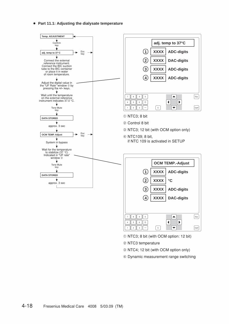
4-18 Fresenius Medical Care 4008 5/03.09 (TM)
7 8 9 0
4
1
5 6
2 3 C Conf
Esc
1
2
3
4
Temp. ADJUSTMENT
Confirmkey
DATA STORED
Connect the externalreference instrument.
Connect the BIC suctiontube to the BIC container
or place it in waterof room temperature.
Tone Mutekey
approx. 3 sec
adj. temp to 37°C Esckey
Adjust the digital value inthe “UF Rate” window ➁ by
pressing the +/– keys.
Wait until the temperature on the external reference
instrument indicates 37.0 °C.
DATA STORED
System in bypass
Tone Mutekey
approx. 3 sec
OCM TEMP. Adjust Esckey
Wait for the temperature to stabilize (37 °C)
Indicated in "UF rate"window ➁
7 8 9 0
4
1
5 6
2 3 C Conf
Esc
adj. temp to 37°C
XXXX ADC-digits
XXXX ADC-digits
XXXX ADC-digits
XXXX DAC-digits
➀ NTC3; 8 bit
➁ Control 8 bit
➂ NTC3; 12 bit (with OCM option only)
➃ NTC109; 8 bit,if NTC 109 is activated in SETUP
OCM TEMP.-Adjust
XXXX ADC-digits
XXXX ADC-digits
XXXX DAC-digits
XXXX °C
➀ NTC3; 8 bit (with OCM option: 12 bit)
➁ NTC3 temperature
➂ NTC4; 12 bit (with OCM option only)
➃ Dynamic measurement range switching
1
2
3
4
● Part 11.1: Adjusting the dialysate temperature
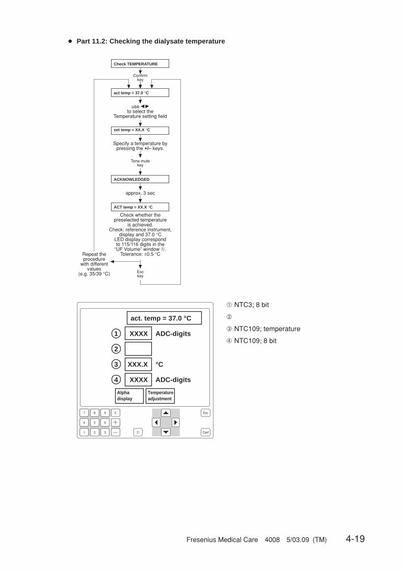
Fresenius Medical Care 4008 5/03.09 (TM) 4-19
7 8 9 0
4
1
5 6
2 3 C Conf
Esc
1
2
3
4
● Part 11.2: Checking the dialysate temperature
Check TEMPERATURE
Confirmkey
use � � to select the
Temperature setting field
act temp = 37.0 °C
Repeat the procedure
with different values
(e.g. 35/39 °C)
Check whether the preselected temperature
is achieved. Check: reference instrument,
display and 37.0 °C LED display correspond to 115/116 digits in the
“UF Volume” window ➀. Tolerance: ±0.5 °C
ACT temp = XX.X °C
Esckey
approx. 3 sec
ACKNOWLEDGED
Tone mutekey
Specify a temperature by pressing the +/– keys.
set temp = XX.X °C
act. temp = 37.0 °C
XXXX ADC-digits
XXX.X °C
XXXX ADC-digits
Alphadisplay
Temperatureadjustment
➀ NTC3; 8 bit
➁
➂ NTC109; temperature
➃ NTC109; 8 bit

4-20 Fresenius Medical Care 4008 5/03.09 (TM)
● Part 11.3: Checking the dialysate temperature for the OCM option
OCM TEMP.-Check
Confirmkey
use � � to select the
Temperature setting field
act temp = 37.0 °C
Repeat the procedure
with different values
(e.g. 35/39 °C)
Check whether the preselected temperature
is achieved. Check: Display,
37.0 °C bargraph displayTolerance of the
displayed temperature in the UF rate field ➁
and the UF time field ➃: ±0.2 °C
ACT temp = XX.X °C
Esckey
approx. 3 sec
ACKNOWLEDGED
Tone Mutekey
Specify a temperature by pressing the +/– keys.
set temp = XX.X °C
Open the shunt coverto switch the systemto the bypass mode
7 8 9 0
4
1
5 6
2 3 C Conf
Esc
1
2
3
4
OCM Temp.-Check
XXXX ADC-digits
XX.XX °C
XXXX ADC-digits
XX.XX °C
Alphadisplay
Temperatureadjustment
➀ NTC3; 12 bit
➁ NTC3; temperature
➂ NTC4; 12 bit
➃ NTC4; temperature
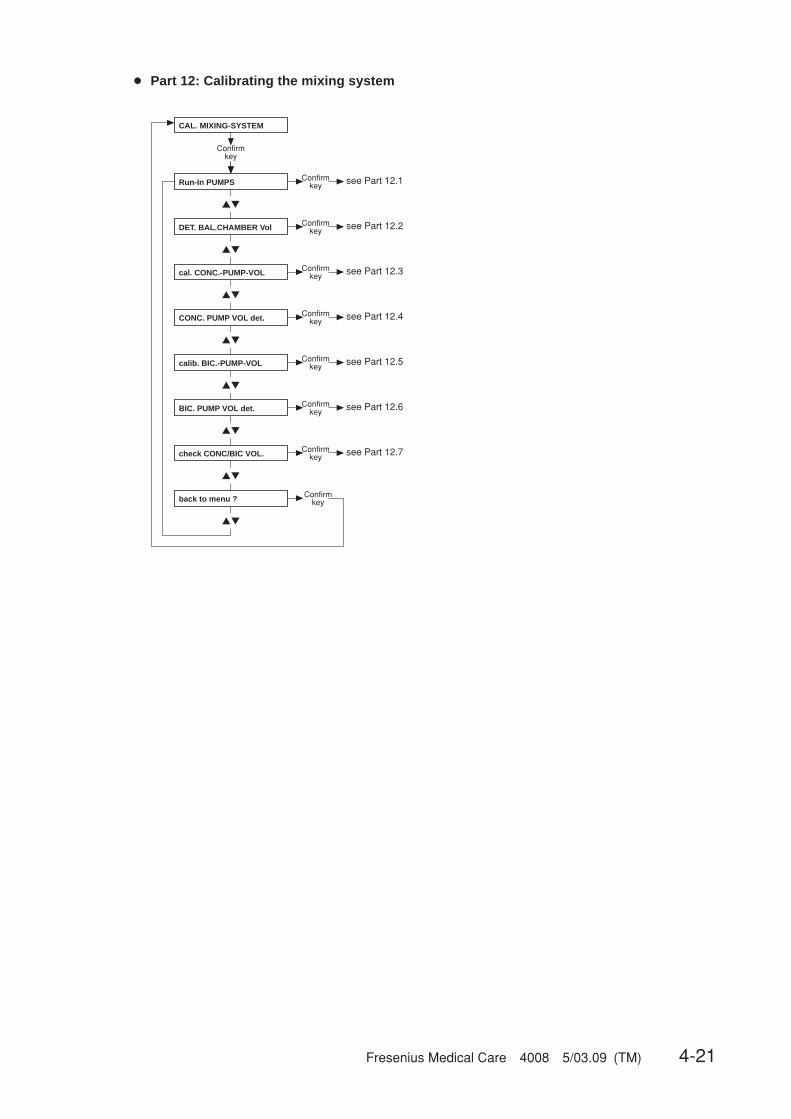
Fresenius Medical Care 4008 5/03.09 (TM) 4-21
▲▼
▲▼
▲▼
▲▼
▲▼
▲▼
▲▼
▲▼
Confirmkey
Confirmkey see Part 12.1
Confirmkey see Part 12.2
Confirmkey see Part 12.3
Confirmkey see Part 12.4
Confirmkey see Part 12.5
Confirmkey see Part 12.6
Confirmkey
Confirmkey see Part 12.7
CAL. MIXING-SYSTEM
Run-In PUMPS
DET. BAL.CHAMBER Vol
cal. CONC.-PUMP-VOL
CONC. PUMP VOL det.
calib. BIC.-PUMP-VOL
BIC. PUMP VOL det.
check CONC/BIC VOL.
back to menu ?
● Part 12: Calibrating the mixing system
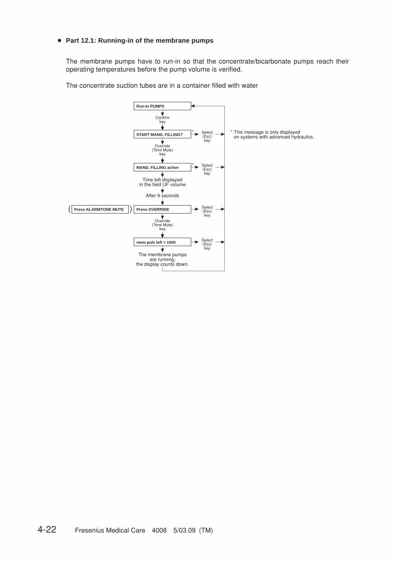
4-22 Fresenius Medical Care 4008 5/03.09 (TM)
( )
*
*
*
Confirmkey
Override(Tone Mute)
key
The membrane pumps are running;
the display counts down.
Select(Esc)key
Select(Esc)key
Select(Esc)key
Override(Tone Mute)
key
Select(Esc)key
Time left displayed in the field UF volume
After 9 seconds
This message is only displayedon systems with advanced hydraulics.
Run-In PUMPS
Press OVERRIDE
mem puls left = 1000
Press ALARMTONE MUTE
START MAND. FILLING?
MAND. FILLING active
● Part 12.1: Running-in of the membrane pumps
The membrane pumps have to run-in so that the concentrate/bicarbonate pumps reach theiroperating temperatures before the pump volume is verified.
The concentrate suction tubes are in a container filled with water
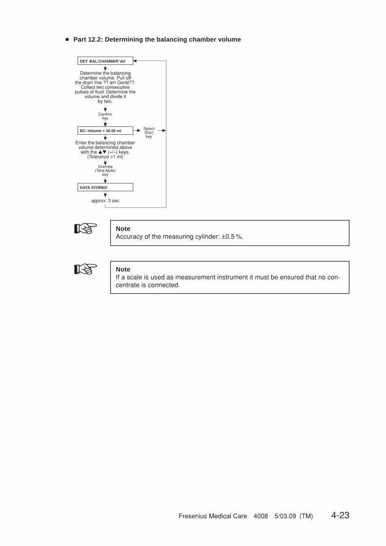
Fresenius Medical Care 4008 5/03.09 (TM) 4-23
Confirmkey
Override(Tone Mute)
key
approx. 3 sec
Select(Esc)key
Determine the balancing chamber volume. Pull off
the drain line ?? am Gerät??. Collect two consecutive
pulses of fluid. Determine the volume and divide it
by two.
Enter the balancing chamber volume determined above with the ▲▼ (+/–) keys.
(Tolerance ±1 ml)
DET. BAL.CHAMBER Vol
BC–Volume = 30.00 ml
DATA STORED
● Part 12.2: Determining the balancing chamber volume
NoteAccuracy of the measuring cylinder: ±0.5 %.
☞ NoteIf a scale is used as measurement instrument it must be ensured that no con-centrate is connected.
☞

4-24 Fresenius Medical Care 4008 5/03.09 (TM)
Confirmkey
Override(Tone Mute)
key
approx. 3 sec
Select(Esc)key
Enter the determined volume of one pump stroke
by pressing the ▲▼ (+/–) keys.
cal. CONC.-PUMP-VOL
CONP-Vol = 0.828 ml
DATA STORED
● Part 12.3: Calibrating the concentrate pump stroke
NoteAccuracy of the measuring cylinder: ±0.5 %.☞

Fresenius Medical Care 4008 5/03.09 (TM) 4-25
( )
*
*
*
Override(Tone Mute)
key
Confirmkey
Override(Tone Mute)
key
Select(Esc)key
approx. 3 sec
Select(Esc)key
The concentrate pump runs for 100 strokes.
The display counts down. Then determine and record
the volume removed by the pump.
Notes:
100 strokes are factory-set. This setting can be changed by pressing the ▲▼ (+/–) keys (depending on the graduated cylinder used). However, when returning to “CAL. MIXING-SYSTEM”, the display will indicate the factory setting again.
Check the volume and, if necessary, repeat the procedure.
Select(Esc)key
Time left displayedin the field UF volume
after 9 seconds
Select(Esc)key
Select(Esc)key
Override(Tone Mute)
key
Select(Esc)key
This message is only displayedon systems with advanced hydraulics.
Press ALARMTONE MUTE
CONC. PUMP VOL det.
conc pulses = 100
ACKNOWLEDGED
Press OVERRIDE
conc puls left = 100
START MAND. FILLING?
MAND. FILLING active
● Part 12.4: Determining the concentrate pump volume
NoteAccuracy of the measuring cylinder: ±0.5 %.
☞ NoteIf a scale is used as measurement instrument it must be ensured that no con-centrate is connected.
☞
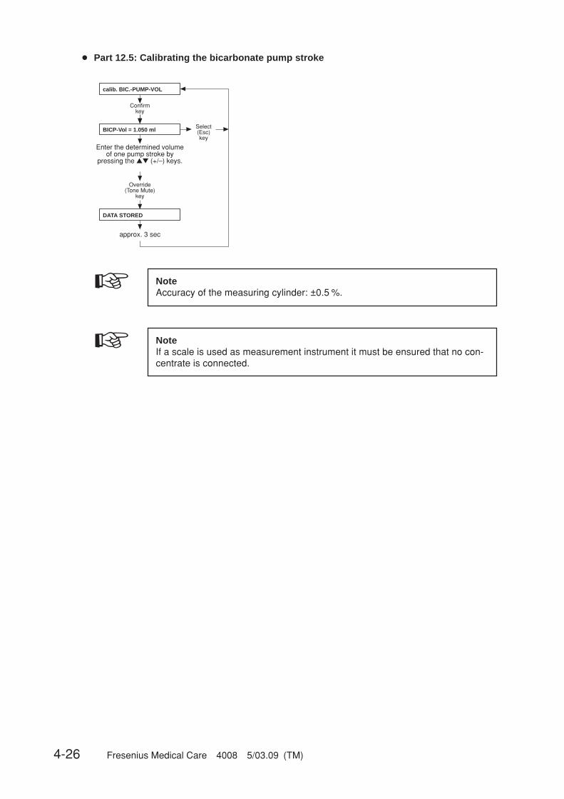
4-26 Fresenius Medical Care 4008 5/03.09 (TM)
Confirmkey
Override(Tone Mute)
key
approx. 3 sec
Select(Esc)key
Enter the determined volume of one pump stroke by
pressing the ▲▼ (+/–) keys.
calib. BIC.-PUMP-VOL
BICP-Vol = 1.050 ml
DATA STORED
● Part 12.5: Calibrating the bicarbonate pump stroke
NoteAccuracy of the measuring cylinder: ±0.5 %.
☞ NoteIf a scale is used as measurement instrument it must be ensured that no con-centrate is connected.
☞
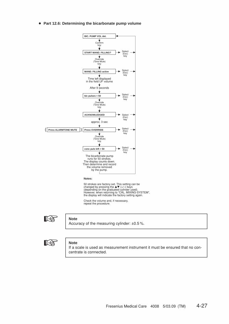
Fresenius Medical Care 4008 5/03.09 (TM) 4-27
( )
Confirmkey
Override(Tone Mute)
key
Select(Esc)key
approx. 3 sec
Select(Esc)key
The bicarbonate pump runs for 50 strokes.
The display counts down. Then determine and record
the volume removed by the pump.
Notes:
50 strokes are factory-set. This setting can be changed by pressing the ▲▼ (+/–) keys (depending on the graduated cylinder used). However, when returning to “CAL. MIXING-SYSTEM”, the display will indicate the factory setting again.
Check the volume and, if necessary, repeat the procedure.
Select(Esc)key
Select(Esc)key
Select(Esc)key
Select(Esc)key
Override(Tone Mute)
key
Override(Tone Mute)
key
Press ALARMTONE MUTE
BIC. PUMP VOL det.
bic pulses = 50
ACKNOWLEDGED
Press OVERRIDE
conc puls left = 50
START MAND. FILLING?
MAND. FILLING active
Time left displayed in the field UF volume
After 9 seconds
● Part 12.6: Determining the bicarbonate pump volume
NoteAccuracy of the measuring cylinder: ±0.5 %.
☞ NoteIf a scale is used as measurement instrument it must be ensured that no con-centrate is connected.
☞

4-28 Fresenius Medical Care 4008 5/03.09 (TM)
( )
Check mixing ratio
Notes:
This test step permits verification of the concentrate or bicarbonate pump volumes in accordance with the parameters entered for the mixing system (mixing ratio, BC volume, conc. and bic. pump volume).
The pump whose concentrate suction tube is pulled off is activated.
50 strokes are factory-set. This setting can be changed by pressing the ▲▼ (+/–) keys (depending on the graduated cylinder used). However, when returning to “CAL. MIXING-SYSTEM”, the display will indicate the factory setting again.
Confirm key
Override (Tone Mute)
key
approx. 3 sec
Select(Esc)key
Select(Esc)key
Override (Tone Mute)
key
The pump runs for 50 strokes.
The display counts down.Then determine and record
the volume removed by the pump and compare it
to the calculated value.
Select(Esc)key
Override (Tone Mute)
key
Select(Esc)key
Select(Esc)key
Select(Esc)key
Time left displayed in the field UF volume
After 9 seconds
Press ALARMTONE MUTE
check CONC/BIC VOL.
ACKNOWLEDGED
Press OVERRIDE
mem puls left = 50
MAND. FILLING active
conc pulses = 100
START MAND. FILLING?
● Part 12.7: Checking the concentrate and/or bicarbonate volume
NoteAccuracy of the measuring cylinder: ±0.5 %.
☞ NoteIf a scale is used as measurement instrument it must be ensured that no con-centrate is connected.
☞
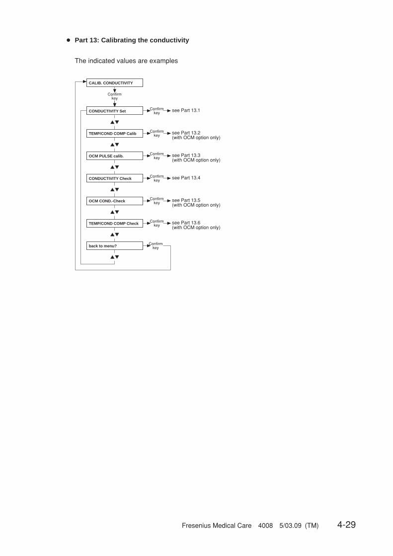
Fresenius Medical Care 4008 5/03.09 (TM) 4-29
● Part 13: Calibrating the conductivity
▲▼
▲▼
▲▼
▲▼
▲▼
▲▼
▲▼
CALIB. CONDUCTIVITY
Confirmkey
CONDUCTIVITY Set Confirmkey see Part 13.1
TEMP/COND COMP Calib Confirmkey see Part 13.2
(with OCM option only)
OCM PULSE calib. Confirmkey see Part 13.3
(with OCM option only)
CONDUCTIVITY Check Confirmkey see Part 13.4
OCM COND.-Check Confirmkey see Part 13.5
(with OCM option only)
TEMP/COND COMP Check Confirmkey see Part 13.6
(with OCM option only)
back to menu? Confirmkey
The indicated values are examples
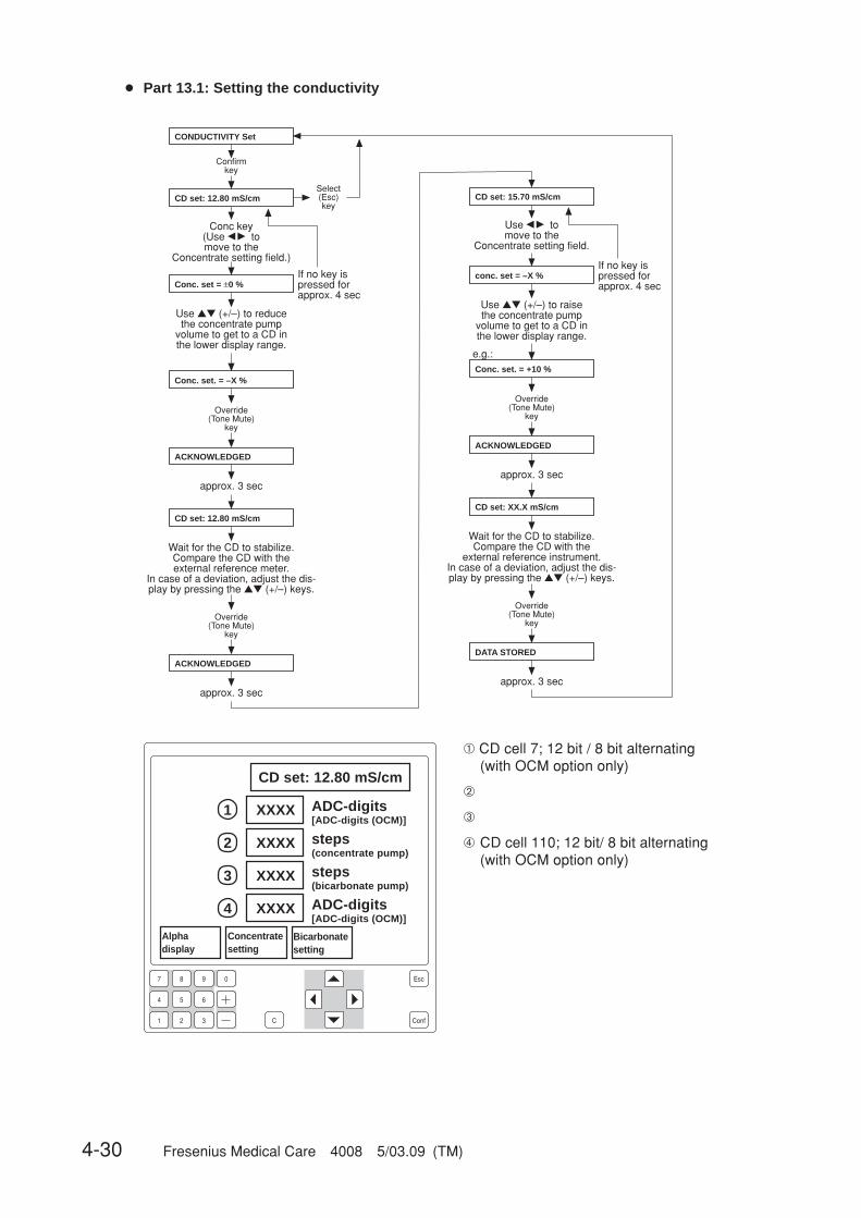
4-30 Fresenius Medical Care 4008 5/03.09 (TM)
7 8 9 0
4
1
5 6
2 3 C Conf
Esc
1
2
3
4
● Part 13.1: Setting the conductivity
CONDUCTIVITY Set
Confirmkey
CD set: 12.80 mS/cm
CD set: 12.80 mS/cm
CD set: 15.70 mS/cmSelect(Esc)key
Conc key(Use � � tomove to the
Concentrate setting field.)
Use ▲▼ (+/–) to reducethe concentrate pump
volume to get to a CD in the lower display range.
Conc. set = ±0 %If no key ispressed forapprox. 4 sec
Override(Tone Mute)
key
ACKNOWLEDGED
approx. 3 sec
Wait for the CD to stabilize.Compare the CD with the external reference meter.
In case of a deviation, adjust the dis-play by pressing the ▲▼ (+/–) keys.
Override(Tone Mute)
key
ACKNOWLEDGED
approx. 3 sec
Use � � tomove to the
Concentrate setting field.
Use ▲▼ (+/–) to raisethe concentrate pump
volume to get to a CD in the lower display range.
conc. set = –X %If no key ispressed forapprox. 4 sec
e.g.:
Override(Tone Mute)
key
Conc. set. = +10 %
ACKNOWLEDGED
approx. 3 sec
CD set: XX.X mS/cm
Wait for the CD to stabilize.Compare the CD with the
external reference instrument. In case of a deviation, adjust the dis-play by pressing the ▲▼ (+/–) keys.
Override(Tone Mute)
key
DATA STORED
approx. 3 sec
Conc. set. = –X %
CD set: 12.80 mS/cm
XXXX ADC-digits[ADC-digits (OCM)]
XXXX steps(concentrate pump)
XXXX steps(bicarbonate pump)
Concentratesetting
XXXX ADC-digits[ADC-digits (OCM)]
Bicarbonatesetting
Alphadisplay
➀ CD cell 7; 12 bit / 8 bit alternating(with OCM option only)
➁
➂
➃ CD cell 110; 12 bit/ 8 bit alternating(with OCM option only)
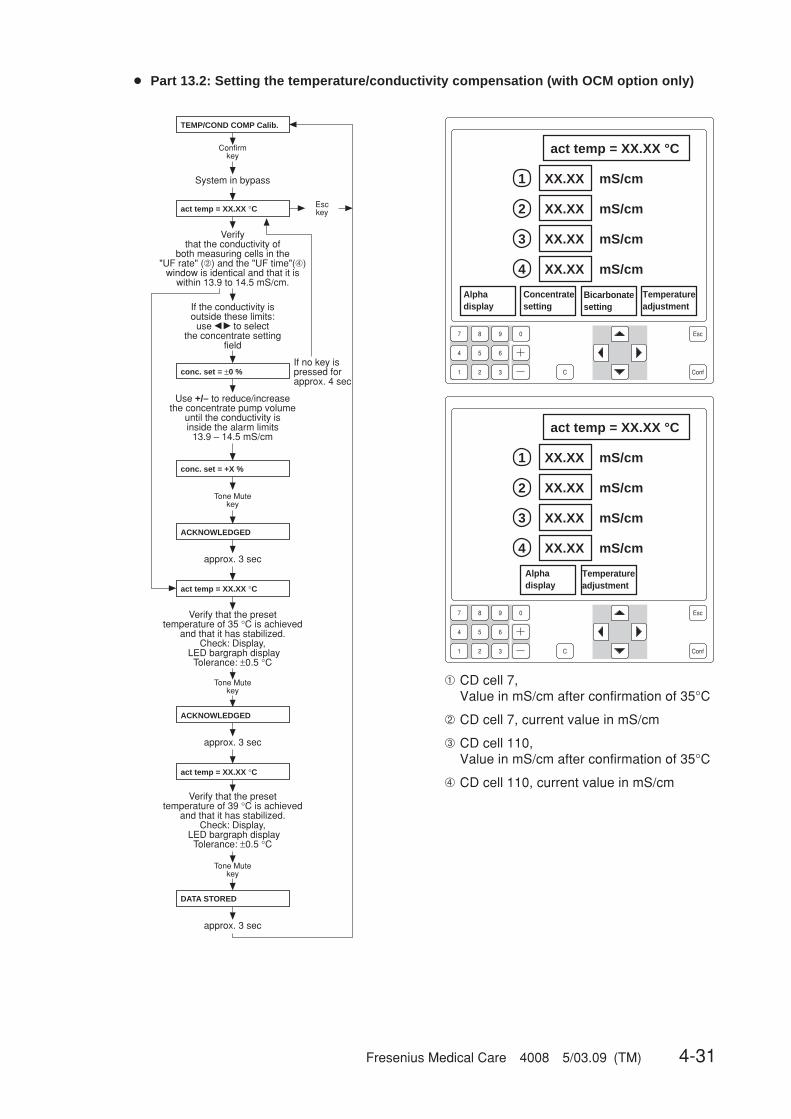
Fresenius Medical Care 4008 5/03.09 (TM) 4-31
7 8 9 0
4
1
5 6
2 3 C Conf
Esc
1
2
3
4
7 8 9 0
4
1
5 6
2 3 C Conf
Esc
1
2
3
4
● Part 13.2: Setting the temperature/conductivity compensation (with OCM option only)
If the conductivity isoutside these limits:
use � � to selectthe concentrate setting
field
TEMP/COND COMP Calib.
Confirmkey
approx. 3 sec
act temp = XX.XX °C Esckey
conc. set = +X %
ACKNOWLEDGED
Tone Mutekey
approx. 3 sec
act temp = XX.XX °C
If no key ispressed for approx. 4 sec
conc. set = ±0 %
Use +/– to reduce/increase the concentrate pump volume
until the conductivity is inside the alarm limits
13.9 – 14.5 mS/cm
Verify that the preset temperature of 35 °C is achieved
and that it has stabilized.Check: Display,
LED bargraph display Tolerance: ±0.5 °C
ACKNOWLEDGED
approx. 3 sec
act temp = XX.XX °C
DATA STORED
Tone Mutekey
Verify that the conductivity of
both measuring cells in the "UF rate" (➁) and the "UF time"(➃)
window is identical and that it is within 13.9 to 14.5 mS/cm.
Tone Mutekey
Verify that the preset temperature of 39 °C is achieved
and that it has stabilized.Check: Display,
LED bargraph display Tolerance: ±0.5 °C
System in bypass
act temp = XX.XX °C
XX.XX mS/cm
Temperatureadjustment
XX.XX mS/cm
XX.XX mS/cm
XX.XX mS/cm
Concentratesetting
Bicarbonatesetting
act temp = XX.XX °C
XX.XX mS/cm
XX.XX mS/cm
XX.XX mS/cm
XX.XX mS/cm
➀ CD cell 7,Value in mS/cm after confirmation of 35°C
➁ CD cell 7, current value in mS/cm
➂ CD cell 110,Value in mS/cm after confirmation of 35°C
➃ CD cell 110, current value in mS/cm
Temperatureadjustment
Alphadisplay
Alphadisplay
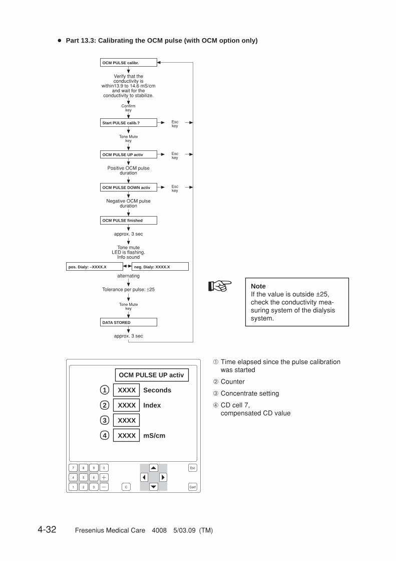
4-32 Fresenius Medical Care 4008 5/03.09 (TM)
● Part 13.3: Calibrating the OCM pulse (with OCM option only)
OCM PULSE calibr.
Confirmkey
DATA STORED
Tone Mutekey
approx. 3 sec
Start PULSE calib.?
Tone Mutekey
Esckey
OCM PULSE UP activ
Positive OCM pulseduration
Esckey
OCM PULSE DOWN activ
Negative OCM pulseduration
Esckey
OCM PULSE finished
approx. 3 sec
Tone muteLED is flashing.
Info sound
pos. Dialy: –XXXX.X neg. Dialy: XXXX.X
alternating
Tolerance per pulse: ±25
Verify that the conductivity is
within13.9 to 14.6 mS/cmand wait for the
conductivity to stabilize.
☞ NoteIf the value is outside ±25,check the conductivity mea-suring system of the dialysissystem.
7 8 9 0
4
1
5 6
2 3 C Conf
Esc
1
2
3
4
OCM PULSE UP activ
XXXX Seconds
XXXX Index
XXXX
XXXX mS/cm
➀ Time elapsed since the pulse calibrationwas started
➁ Counter
➂ Concentrate setting
➃ CD cell 7,compensated CD value
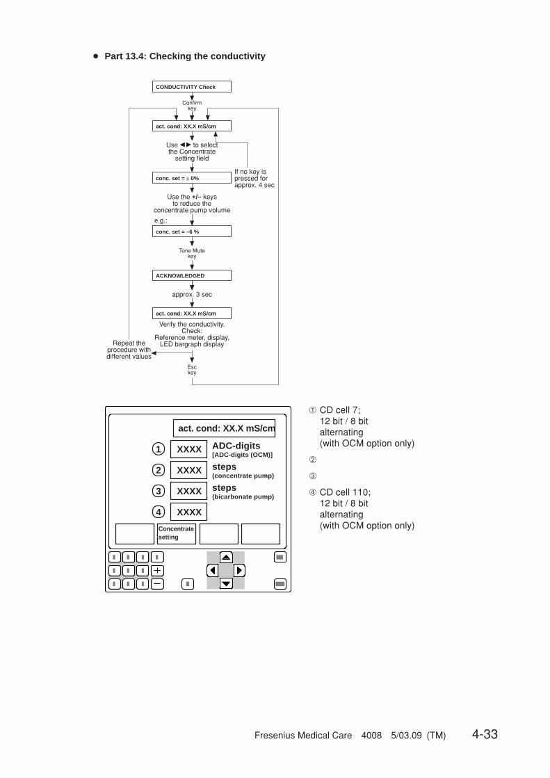
Fresenius Medical Care 4008 5/03.09 (TM) 4-33
1
2
3
4
● Part 13.4: Checking the conductivity
CONDUCTIVITY Check
Confirmkey
act. cond: XX.X mS/cm
Use � � to select the Concentrate
setting field
Esckey
Verify the conductivity.Check:
Reference meter, display,LED bargraph display
conc. set = ± 0%
Use the +/– keysto reduce the
concentrate pump volume
approx. 3 sec
act. cond: XX.X mS/cm
Repeat theprocedure with different values
If no key ispressed forapprox. 4 sec
conc. set = –6 %
ACKNOWLEDGED
Tone Mutekey
e.g.:
➀ CD cell 7;12 bit / 8 bitalternating(with OCM option only)
➁
➂
➃ CD cell 110;12 bit / 8 bitalternating(with OCM option only)
act. cond: XX.X mS/cm
XXXX
XXXX
XXXX
XXXX
ADC-digits[ADC-digits (OCM)]
steps(concentrate pump)
steps(bicarbonate pump)
Concentratesetting
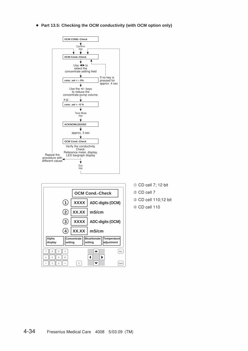
4-34 Fresenius Medical Care 4008 5/03.09 (TM)
7 8 9 0
4
1
5 6
2 3 C Conf
Esc
1
2
3
4
● Part 13.5: Checking the OCM conductivity (with OCM option only)
OCM COND.-Check
Confirmkey
OCM Cond.-Check
Use � � toselect the
concentrate setting field
Esckey
Verify the conductivity.Check:
Reference meter, display,LED bargraph display
conc. set = ± 0%
Use the +/– keys to reduce the
concentrate pump volume.
approx. 3 sec
OCM Cond.-Check
Repeat the procedure with different values
If no key ispressed forapprox. 4 sec
conc. set = –6 %
ACKNOWLEDGED
Tone Mutekey
e.g.:
➀ CD cell 7; 12 bit
➁ CD cell 7
➂ CD cell 110;12 bit
➃ CD cell 110
OCM Cond.-Check
XXXX ADC-digits (OCM)
XX.XX mS/cm
XXXX ADC-digits (OCM)
XX.XX mS/cm
Alphadisplay
Concentratesetting
Temperatureadjustment
Bicarbonatesetting

Fresenius Medical Care 4008 5/03.09 (TM) 4-35
● Part 13.6: Temperature/conductivity compensation test (with OCM option only)
The individual conductivities and their
compensation factors are displayed in the fields
(see 4008 H/S)
TEMP/COND COMP Check
Confirmkey
act temp = XX.XX °C
The conductivity cells can be crosschecked
by changing the concentration
or temperature.
Esckey
➀ CD cell 7, compensated
➁ CD cell 7, compensation factor
➂ CD cell 110, compensated
➃ CD cell 110, compensation factor
7 8 9 0
4
1
5 6
2 3 C Conf
Esc
1
2
3
4
act temp = XX.XX °C
XX.XX mS/cm
XXXX mS/(cm•°C)
XX.XX mS/cm
XXXX mS/(cm•°C)
Alphadisplay
Concentratesetting
Temperatureadjustment
Bicarbonatesetting

4-36 Fresenius Medical Care 4008 5/03.09 (TM)
● Part 14: Calibrating the dialysate pressure (stainless steel pressure transducer)
▲▼
▲▼
▲▼
▲▼
Confirmkey
Confirmkey see Part 14.1
Confirmkey see Part 14.2
Confirmkey see Part 14.3
Confirmkey
CAL. DIAL. PRESSURE
DIALYSATE Pressure
TMP-Check
PDIAL2 press-check
back to menu ?
☞ NoteMeasuring instrument accuracy: ±1 % of the measured value.

Fresenius Medical Care 4008 5/03.09 (TM) 4-37
● Part 14.1: Dialysate pressure
Confirmkey
Open the dialysate circuit. Flow off / UF off.
The dialysate pressure approaches “0”.
Set “0” mmHg on the display by pressing the ▲▼ (+/–) keys.
Close thedialysate circuit.
Switch on the flow.
Switch on the UF pump bypressing the UF I/O key.
Leave the UF pump running until approx. –500 mmHg are
indicated by the external reference instrument.
Switch off the flow.
Use the potentiometer P3/LP 633 to set the value indicated by the external reference
instrument on the alphanumeric display.
Repeatthe procedure
until 0 and –500 mmHg correspond
to the external comparison instrument.
Select(Esc)key
notOK
OK
Open thedialysate circuit.
Override(Tone Mute)
key
approx. 3 sec
approx. 3 sec
Close thedialysate circuit.
Switch on the UF pumpby pressing the UF I/O key.
Override(Tone Mute)
key
Leave the UF pump running, until approx. 500 mmHg are
indicated by the external reference instrument.
Switch off the flow.
Switch on the flow.
Enter the value indicated by the external reference instrument
by pressing the ▲▼ (+/–) keys.
Override(Tone Mute)
key
Open the dialysate circuit. After the system has recognized that the circuit is open, the flow
is switched on automatically.
The Override LED is flashing.
DIALYSATE Pressure
adj.zero.: + XXX mmHg
adj.zero.: ± 0 mmHg
DATA STORED
ACKNOWLEDGED
dia.gain.: – 500 mmHg
OPEN SYSTEM
Wait for OVERRID.LED
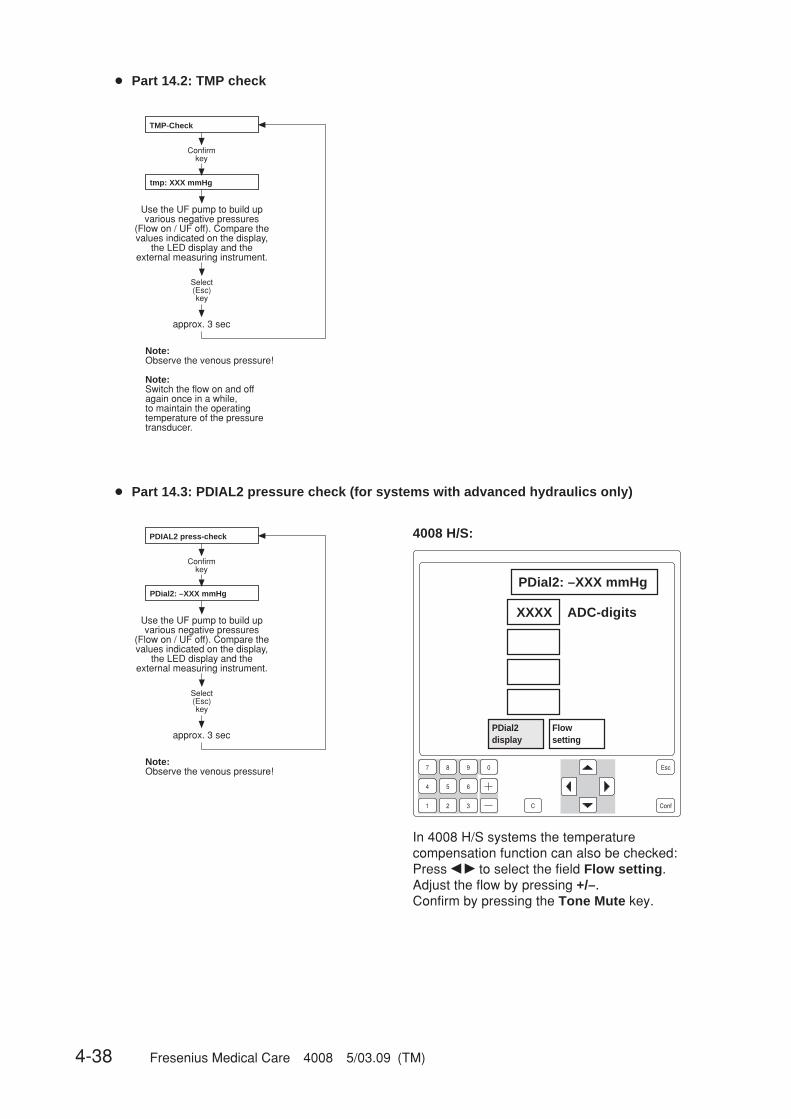
4-38 Fresenius Medical Care 4008 5/03.09 (TM)
● Part 14.2: TMP check
Confirmkey
Use the UF pump to build up various negative pressures
(Flow on / UF off). Compare the values indicated on the display,
the LED display and the external measuring instrument.
approx. 3 sec
Note:Observe the venous pressure!
Note:Switch the flow on and offagain once in a while,to maintain the operatingtemperature of the pressuretransducer.
Select(Esc)key
TMP-Check
tmp: XXX mmHg
● Part 14.3: PDIAL2 pressure check (for systems with advanced hydraulics only)
Confirmkey
Use the UF pump to build up various negative pressures
(Flow on / UF off). Compare the values indicated on the display,
the LED display and the external measuring instrument.
approx. 3 sec
Note:Observe the venous pressure!
Select(Esc)key
PDIAL2 press-check
PDial2: –XXX mmHg
7 8 9 0
4
1
5 6
2 3 C Conf
Esc
PDial2: –XXX mmHg
XXXX ADC-digits
4008 H/S:
PDial2display
Flowsetting
In 4008 H/S systems the temperaturecompensation function can also be checked:Press � � to select the field Flow setting.Adjust the flow by pressing +/–.Confirm by pressing the Tone Mute key.
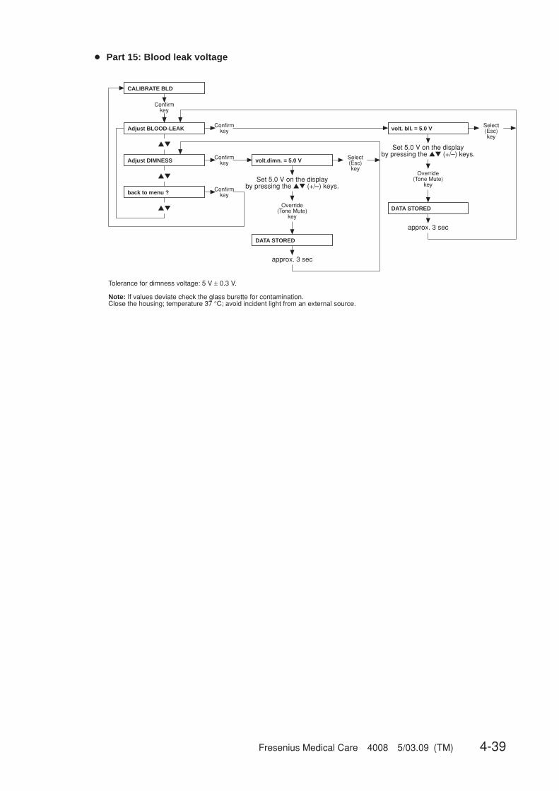
Fresenius Medical Care 4008 5/03.09 (TM) 4-39
● Part 15: Blood leak voltage
▲▼
▲▼
▲▼
Confirmkey
Confirmkey
Confirmkey
Confirmkey
Set 5.0 V on the display by pressing the ▲▼ (+/–) keys.
Override(Tone Mute)
key
approx. 3 sec
Select(Esc)key
Set 5.0 V on the display by pressing the ▲▼ (+/–) keys.
Override(Tone Mute)
key
approx. 3 sec
Select(Esc)key
Tolerance for dimness voltage: 5 V ± 0.3 V.
Note: If values deviate check the glass burette for contamination.Close the housing; temperature 37 °C; avoid incident light from an external source.
Adjust BLOOD-LEAK
Adjust DIMNESS
back to menu ?
CALIBRATE BLD
DATA STORED
volt. bll. = 5.0 V
DATA STORED
volt.dimn. = 5.0 V
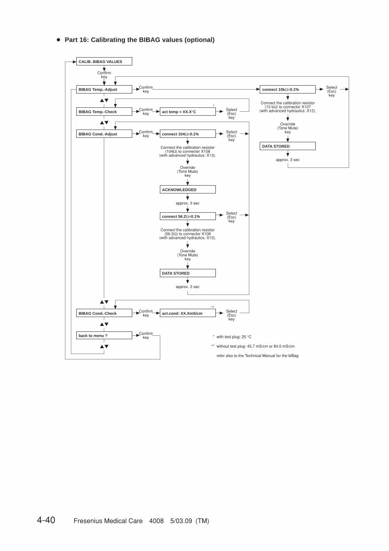
4-40 Fresenius Medical Care 4008 5/03.09 (TM)
● Part 16: Calibrating the BIBAG values (optional)
▲▼
▲▼
▲▼
▲▼
▲▼
*
**
*
**
Confirmkey
Confirmkey
Confirmkey
Confirmkey
Connect the calibration resistor (10 kΩ) to connector X107
(with advanced hydraulics: X12).
Override(Tone Mute)
key
approx. 3 sec
Select(Esc)key
Override(Tone Mute)
key
approx. 3 sec
Confirmkey
Select(Esc)key
Connect the calibration resistor(56.2Ω) to connector X108
(with advanced hydraulics: X13).
Override(Tone Mute)
key
approx. 3 sec
Confirmkey
Select(Esc)key
Select(Esc)key
Select(Esc)key
Connect the calibration resistor (104Ω) to connector X108
(with advanced hydraulics: X13).
with test plug: 25 °C
without test plug: 45,7 mS/cm or 84,5 mS/cm
refer also to the Technical Manual for the biBag
BIBAG Temp.-Adjust
BIBAG Cond.-Adjust
back to menu ?
CALIB. BIBAG VALUES
connect 104Ω±0.1%
DATA STORED
connect 10kΩ±0.1%
ACKNOWLEDGED
BIBAG Temp.-Check act temp = XX.X°C
connect 56.2Ω±0.1%
DATA STORED
BIBAG Cond.-Check act.cond: XX.XmS/cm

Fresenius Medical Care 4008 5/03.09 (TM) 4-41
● Part 17: Resetting the failure record
Confirmkey
Override(Tone Mute)
key
approx. 3 sec
Select(Esc)key
audible alarm
RESET FAILURE RECORD
Are you sure ?
ACKNOWLEDGED
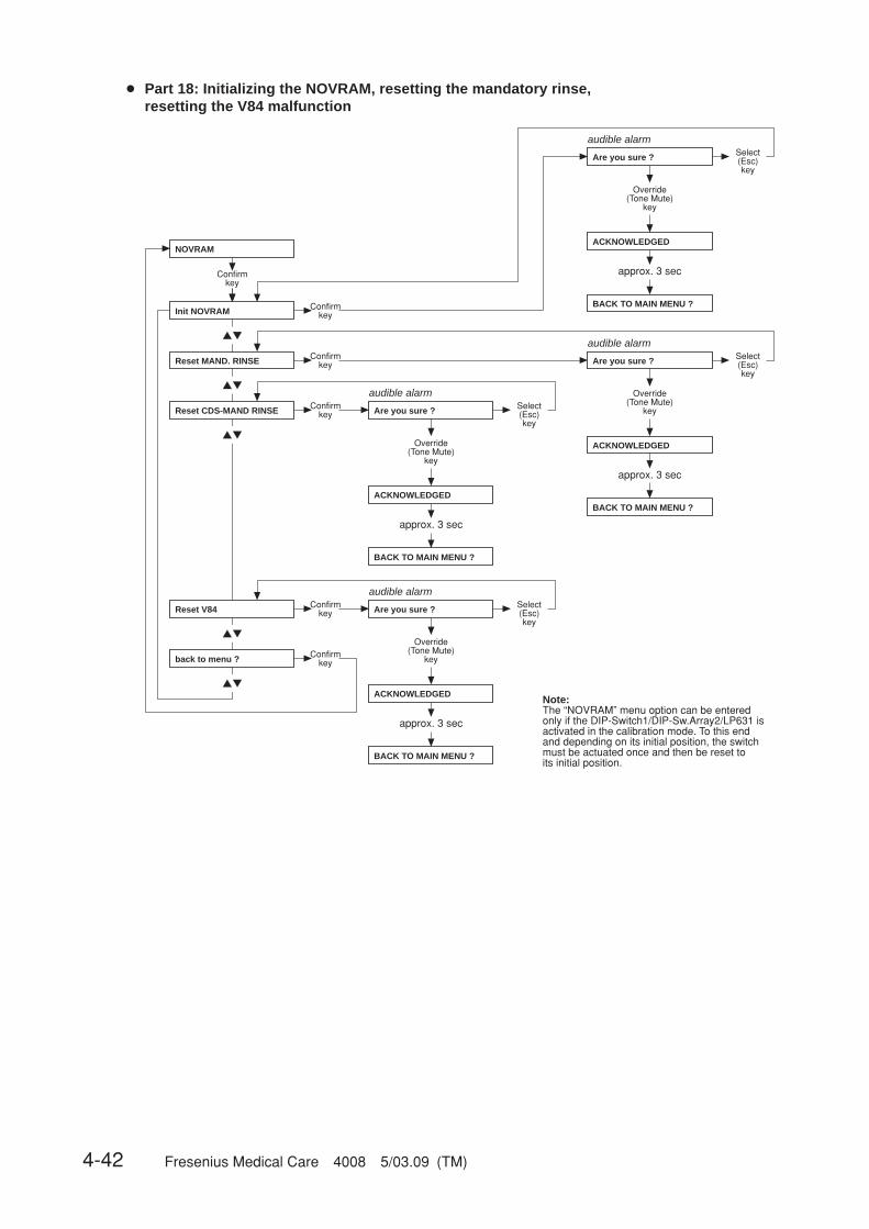
4-42 Fresenius Medical Care 4008 5/03.09 (TM)
● Part 18: Initializing the NOVRAM, resetting the mandatory rinse,resetting the V84 malfunction
▲▼
▲▼
▲▼
▲▼
▲▼
Confirmkey
Confirmkey
Confirmkey
Override(Tone Mute)
key
approx. 3 sec
Select(Esc)key
audible alarm
Confirmkey
Override(Tone Mute)
key
approx. 3 sec
Select(Esc)key
audible alarm
Confirmkey
Override(Tone Mute)
key
approx. 3 sec
Select(Esc)key
audible alarm
Note:The “NOVRAM” menu option can be entered only if the DIP-Switch1/DIP-Sw.Array2/LP631 is activated in the calibration mode. To this end and depending on its initial position, the switch must be actuated once and then be reset to its initial position.
Confirmkey
Override(Tone Mute)
key
approx. 3 sec
Select(Esc)key
audible alarm
Init NOVRAM
Reset V84
back to menu ?
NOVRAM
ACKNOWLEDGED
Are you sure ?
Reset MAND. RINSE
BACK TO MAIN MENU ?
ACKNOWLEDGED
Are you sure ?
BACK TO MAIN MENU ?
ACKNOWLEDGED
Are you sure ?
BACK TO MAIN MENU ?
Reset CDS-MAND RINSE
ACKNOWLEDGED
Are you sure ?
BACK TO MAIN MENU ?

Fresenius Medical Care 4008 5/03.09 (TM) 4-43
● Without menu display: Adjusting the Hall sensor in the heparin pump
Adjustment of Hall sensor 1– Remove plug connector from Hall sensor 2.– Move the slide carriage down over Hall sensor 1.– Move the slide carriage up to its fully open position.– Move the slide carriage down again to the end of its travel.– The free motion between the slide carriage and the housing should be approx. 0.5 mm. If
necessary, change the position of Hall sensor 1 and repeat the procedure.
Adjustment of Hall sensor 2– Reconnect plug connector for Hall sensor 2.– Move the slide carriage down to approx. 2 cm before the end of its travel.– Manually turn the threaded spindle approx. 2-3 rotations in delivery direction.– Move the slide carriage down.– The slide carriage must stop before the mechanical end of its travel. If necessary, change the
position of Hall sensor 2 and repeat the procedure several times.
Hall sensor 1
Hall sensor 2

4-44 Fresenius Medical Care 4008 5/03.09 (TM)
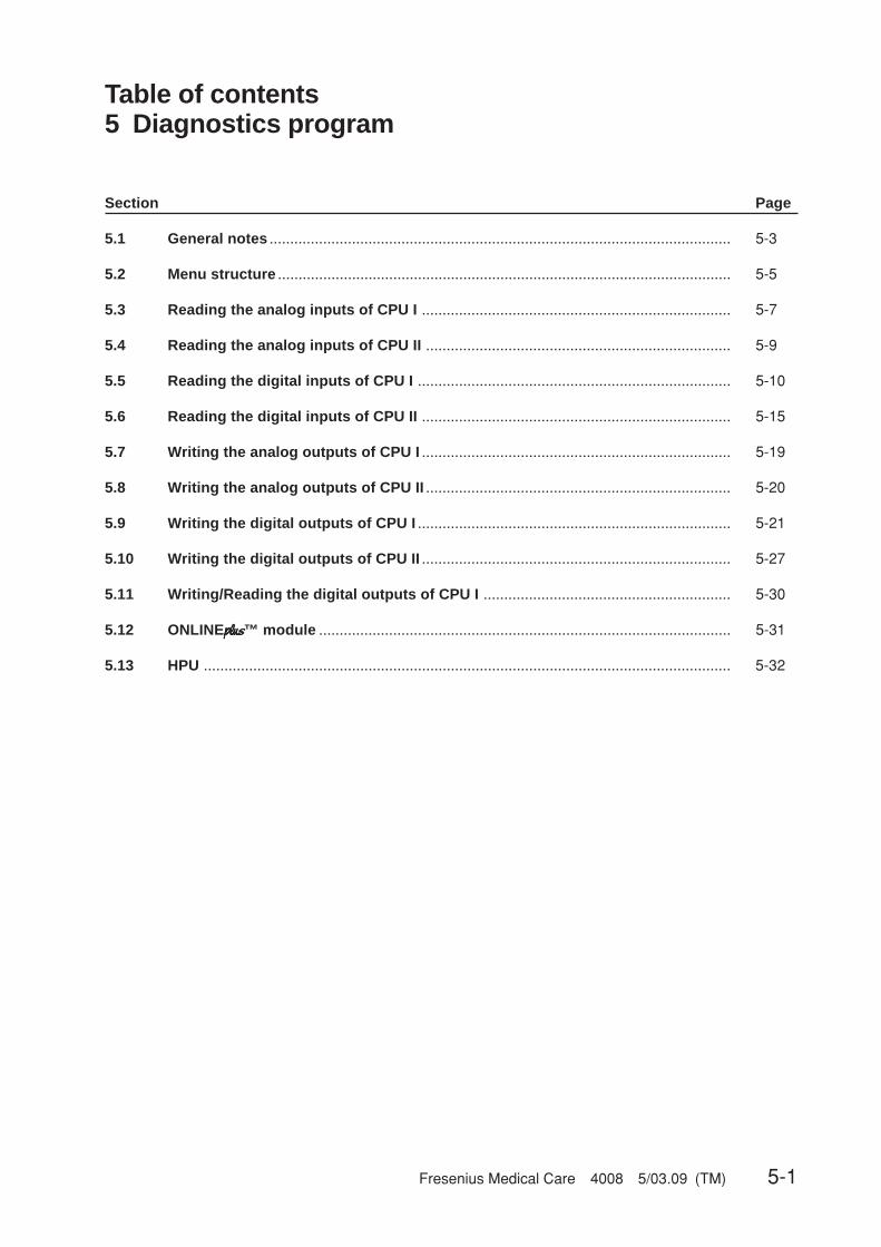
Fresenius Medical Care 4008 5/03.09 (TM) 5-1
Table of contents5 Diagnostics program
Section Page
5.1 General notes ................................................................................................................ 5-3
5.2 Menu structure .............................................................................................................. 5-5
5.3 Reading the analog inputs of CPU I ........................................................................... 5-7
5.4 Reading the analog inputs of CPU II .......................................................................... 5-9
5.5 Reading the digital inputs of CPU I ............................................................................ 5-10
5.6 Reading the digital inputs of CPU II ........................................................................... 5-15
5.7 Writing the analog outputs of CPU I ........................................................................... 5-19
5.8 Writing the analog outputs of CPU II .......................................................................... 5-20
5.9 Writing the digital outputs of CPU I ............................................................................ 5-21
5.10 Writing the digital outputs of CPU II ........................................................................... 5-27
5.11 Writing/Reading the digital outputs of CPU I ............................................................ 5-30
5.12 ONLINEplusplusplusplusplus™ module .................................................................................................... 5-31
5.13 HPU ................................................................................................................................ 5-32

5-2 Fresenius Medical Care 4008 5/03.09 (TM)
Fresenius Medical Care 4008 5/03.09 (TM) 5-3
5.1 General notes
The diagnostics program serves to activate all inputs and outputs of the hemodialysis system.Activation is related to CPU1 (P.C.B. LP 631), CPU2 (P.C.B. LP 632), as well as to the outputboard (P.C.B. LP 634) and the input board (P.C.B. LP 633).
Using this program, the technician is able to program his own settings for testing of error images.
The diagnostics program is divided into the following menus:– READ INPUTS
– READ ANALOG INPUTS– CPU1: RD ANALOG INP.– CPU2: RD ANALOG INP.
– READ DIGITAL INPUTS– CPU1: RD DIGITAL INP– CPU2: RD DIGITAL INP
– WRITE OUTPUTS– WRITE ANALOG OUTPUTS
– CPU1: WR ANALOG OUTP– CPU2: WR ANALOG OUTP
– WRITE DIGIT. OUTPUTS– CPU1: WR DIGIT. OUTP– CPU2: WR DIGIT. OUTP
– INP/OUTP COMBINATION– CPU1: COMBINATION
– CAN–COMPONENTS– HPU– ONLINE–PLUS–MODUL
In order to indicate the corresponding levels, all UF-seven-segment displays as well as the statusindicator (monitor), the external traffic light and the loudspeaker are used in the “READ DIGITALINPUTS” menu.
The active signal state (which may correspond to both present and absent voltage) is indicated by1111 on the UF displays, activated traffic light (status indicator) and audible signal.An audible signal can be deactivated by pressing the (Alarm) Tone Mute key. With the audiblesignal deactivated, the (Alarm) Tone Mute LED is flashing as a reminder.
The audible signal indication can be used to evaluate the state of the signal without having to lookat the monitor. This may be advantageous in case measurements have to be made behind thesystem (e.g. hydraulic unit).
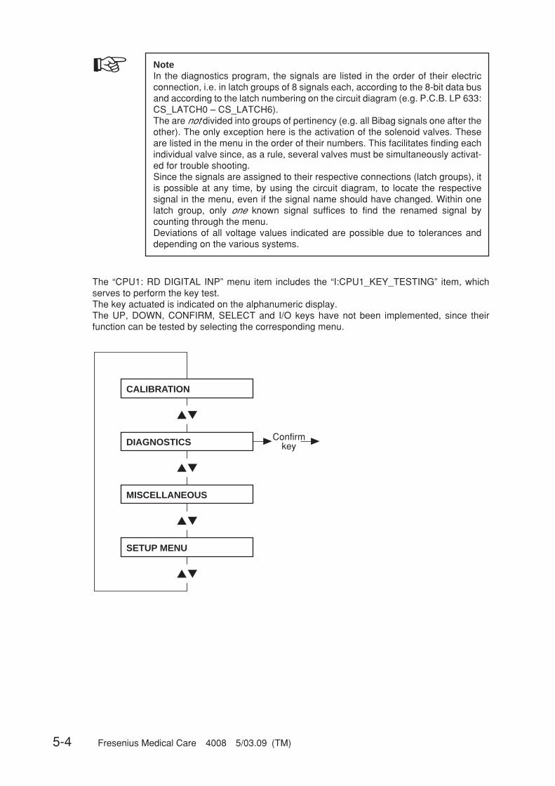
5-4 Fresenius Medical Care 4008 5/03.09 (TM)
☞ NoteIn the diagnostics program, the signals are listed in the order of their electricconnection, i.e. in latch groups of 8 signals each, according to the 8-bit data busand according to the latch numbering on the circuit diagram (e.g. P.C.B. LP 633:CS_LATCH0 – CS_LATCH6).The are not divided into groups of pertinency (e.g. all Bibag signals one after theother). The only exception here is the activation of the solenoid valves. Theseare listed in the menu in the order of their numbers. This facilitates finding eachindividual valve since, as a rule, several valves must be simultaneously activat-ed for trouble shooting.Since the signals are assigned to their respective connections (latch groups), itis possible at any time, by using the circuit diagram, to locate the respectivesignal in the menu, even if the signal name should have changed. Within onelatch group, only one known signal suffices to find the renamed signal bycounting through the menu.Deviations of all voltage values indicated are possible due to tolerances anddepending on the various systems.
▲▼
▲▼
▲▼
▲▼
CALIBRATION
ConfirmkeyDIAGNOSTICS
MISCELLANEOUS
SETUP MENU
The “CPU1: RD DIGITAL INP” menu item includes the “I:CPU1_KEY_TESTING” item, whichserves to perform the key test.The key actuated is indicated on the alphanumeric display.The UP, DOWN, CONFIRM, SELECT and I/O keys have not been implemented, since theirfunction can be tested by selecting the corresponding menu.
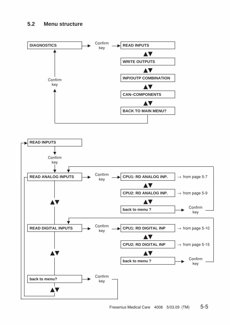
Fresenius Medical Care 4008 5/03.09 (TM) 5-5
READ ANALOG INPUTS �Confirm
key� → from page 5-7CPU1: RD ANALOG INP.
��
→ from page 5-9CPU2: RD ANALOG INP.
��
back to menu ?
READ INPUTS
�
�
�Confirm
key
READ DIGITAL INPUTS �Confirm
key� → from page 5-10CPU1: RD DIGITAL INP
��
→ from page 5-15CPU2: RD DIGITAL INP
back to menu ?
��
�Confirm
key
��
��
back to menu?
��
�
�
Confirmkey
�Confirm
key
�
5.2 Menu structure
DIAGNOSTICS �Confirm
key� READ INPUTS
��
WRITE OUTPUTS
��
INP/OUTP COMBINATION
��
BACK TO MAIN MENU?
Confirmkey�
�
CAN–COMPONENTS
��
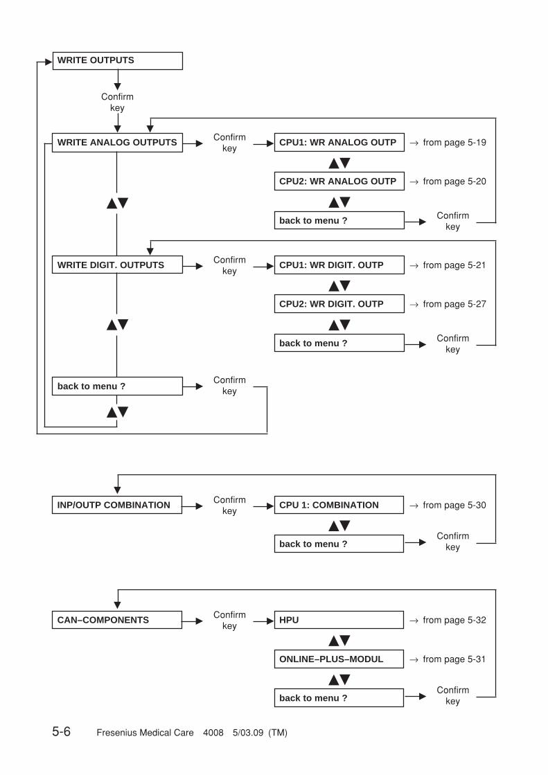
5-6 Fresenius Medical Care 4008 5/03.09 (TM)
INP/OUTP COMBINATION �Confirm
key� → from page 5-30CPU 1: COMBINATION
�
��
back to menu ? �Confirm
key
WRITE ANALOG OUTPUTS �Confirm
key� → from page 5-19CPU1: WR ANALOG OUTP
��
→ from page 5-20CPU2: WR ANALOG OUTP
��
back to menu ?
WRITE OUTPUTS
�
�
�Confirm
key
WRITE DIGIT. OUTPUTS �Confirm
key� → from page 5-21CPU1: WR DIGIT. OUTP
��
→ from page 5-27CPU2: WR DIGIT. OUTP
back to menu ?
��
�Confirm
key
��
��
back to menu ?
��
�
�
Confirmkey
�Confirm
key
�
CAN–COMPONENTS �Confirm
key� HPU
�
��
back to menu ? �Confirm
key
→ from page 5-31ONLINE–PLUS–MODUL
��
→ from page 5-32
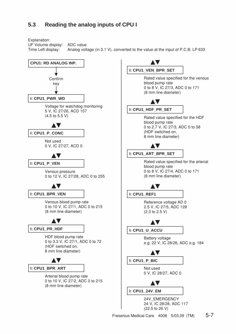
Fresenius Medical Care 4008 5/03.09 (TM) 5-7
I: CPU1_PWR_WD
CPU1: RD ANALOG INP.
�
Confirmkey
�
Voltage for watchdog monitoring5 V, IC 27/26, ACD 107(4.5 to 5.5 V)
��
��
��
I: CPU1_P_CONC
��
��
��
I: CPU1_P_VEN
I: CPU1_BPR_VEN
I: CPU1_PR_HDF
I: CPU1_BPR_ART
I: CPU1_HDF_PR_SET
��
��
��
��
��
I: CPU1_ART_BPR_SET
Rated value specified for the arterialblood pump rate0 to 8 V, IC 27/4, ADC 0 to 171(8 mm line diameter)
I: CPU1_REF1
Reference voltage AD 02.5 V, IC 27/5, ADC 128(2.3 to 2.5 V)
I: CPU1_U_ACCU
Battery voltagee.g. 22 V, IC 28/26, ADC e.g. 184
I: CPU1_P_BIC
Not used0 V, IC 28/27, ADC 0
I: CPU1_24V_EM
24V_EMERGENCY24 V, IC 28/28, ADC 117(22.5 to 26 V)
Not used0 V, IC 27/27, ACD 0
Venous pressure0 to 12 V, IC 27/28, ADC 0 to 255
Venous blood pump rate0 to 10 V, IC 27/1, ADC 0 to 215(8 mm line diameter)
HDF blood pump rate0 to 3.3 V, IC 27/1, ADC 0 to 72(HDF switched on,8 mm line diameter)
Arterial blood pump rate0 to 10 V, IC 27/2, ADC 0 to 215(8 mm line diameter)
��
I: CPU1_VEN_BPR_SET
Rated value specified for the venousblood pump rate0 to 8 V, IC 27/3, ADC 0 to 171(8 mm line diameter)
5.3 Reading the analog inputs of CPU I
Explanation:UF Volume display: ADC valueTime Left display: Analog voltage (in 0.1 V), converted to the value at the input of P.C.B. LP 633
Rated value specified for the HDFblood pump rate0 to 2.7 V, IC 27/3, ADC 0 to 58(HDF switched on,8 mm line diameter)
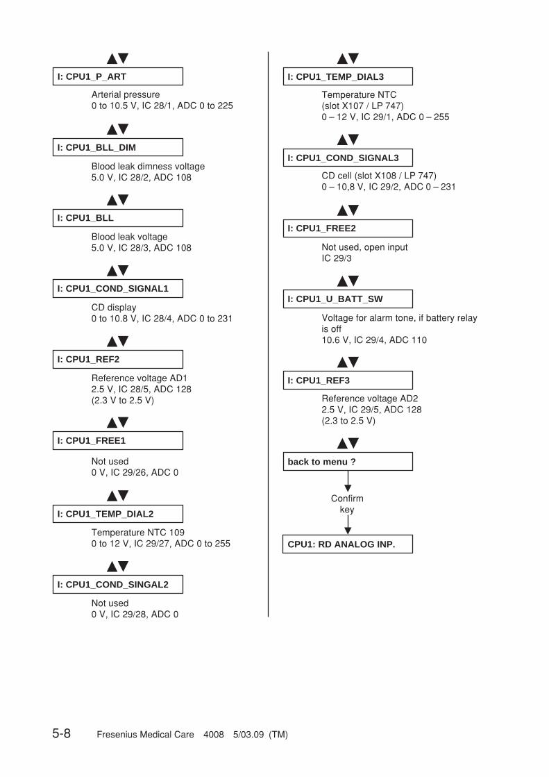
5-8 Fresenius Medical Care 4008 5/03.09 (TM)
����
��
��
��
��
��
��
��
��
��
��
�
�
I: CPU1_BLL_DIM
Blood leak dimness voltage5.0 V, IC 28/2, ADC 108
I: CPU1_BLL
Blood leak voltage5.0 V, IC 28/3, ADC 108
I: CPU1_COND_SIGNAL1
CD display0 to 10.8 V, IC 28/4, ADC 0 to 231
I: CPU1_REF2
Reference voltage AD12.5 V, IC 28/5, ADC 128(2.3 V to 2.5 V)
I: CPU1_FREE1
Not used0 V, IC 29/26, ADC 0
I: CPU1_TEMP_DIAL2
Temperature NTC 1090 to 12 V, IC 29/27, ADC 0 to 255
I: CPU1_COND_SINGAL2
Not used0 V, IC 29/28, ADC 0
I: CPU1_COND_SIGNAL3
CD cell (slot X108 / LP 747)0 – 10,8 V, IC 29/2, ADC 0 – 231
I: CPU1_FREE2
Not used, open inputIC 29/3
I: CPU1_U_BATT_SW
Voltage for alarm tone, if battery relayis off10.6 V, IC 29/4, ADC 110
I: CPU1_REF3
Reference voltage AD22.5 V, IC 29/5, ADC 128(2.3 to 2.5 V)
back to menu ?
Confirmkey
CPU1: RD ANALOG INP.
��
I: CPU1_P_ART
Arterial pressure0 to 10.5 V, IC 28/1, ADC 0 to 225
��
I: CPU1_TEMP_DIAL3
Temperature NTC(slot X107 / LP 747)0 – 12 V, IC 29/1, ADC 0 – 255
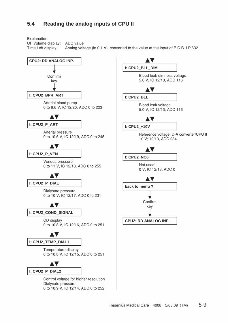
Fresenius Medical Care 4008 5/03.09 (TM) 5-9
5.4 Reading the analog inputs of CPU II
Explanation:UF Volume display: ADC valueTime Left display: Analog voltage (in 0.1 V), converted to the value at the input of P.C.B. LP 632
�
�
��
��
��
��
��
��
��
��
��
��
��
�
�
CPU2: RD ANALOG INP.
Confirmkey
I: CPU2_BPR_ART
Arterial blood pump0 to 9.6 V, IC 12/20, ADC 0 to 223
I: CPU2_P_ART
Arterial pressure0 to 10.6 V, IC 12/19, ADC 0 to 245
I: CPU2_P_VEN
Venous pressure0 to 11 V, IC 12/18, ADC 0 to 255
I: CPU2_P_DIAL
Dialysate pressure0 to 10 V, IC 12/17, ADC 0 to 231
I: CPU2_COND_SIGNAL
CD display0 to 10.8 V, IC 12/16, ADC 0 to 251
I: CPU2_TEMP_DIAL1
Temperature display0 to 10.8 V, IC 12/15, ADC 0 to 251
I: CPU2_P_DIAL2
Control voltage for higher resolutionDialysate pressure0 to 10.9 V, IC 12/14, ADC 0 to 252
I: CPU2_BLL_DIM
Blood leak dimness voltage5.0 V, IC 12/13, ADC 116
I: CPU2_BLL
Blood leak voltage5.0 V, IC 12/13, ADC 116
I: CPU2_+10V
Reference voltage, D-A converter/CPU II10 V; 12/13, ADC 234
I: CPU2_NC6
Not used0 V, IC 12/13, ADC 0
back to menu ?
Confirmkey
CPU2: RD ANALOG INP.
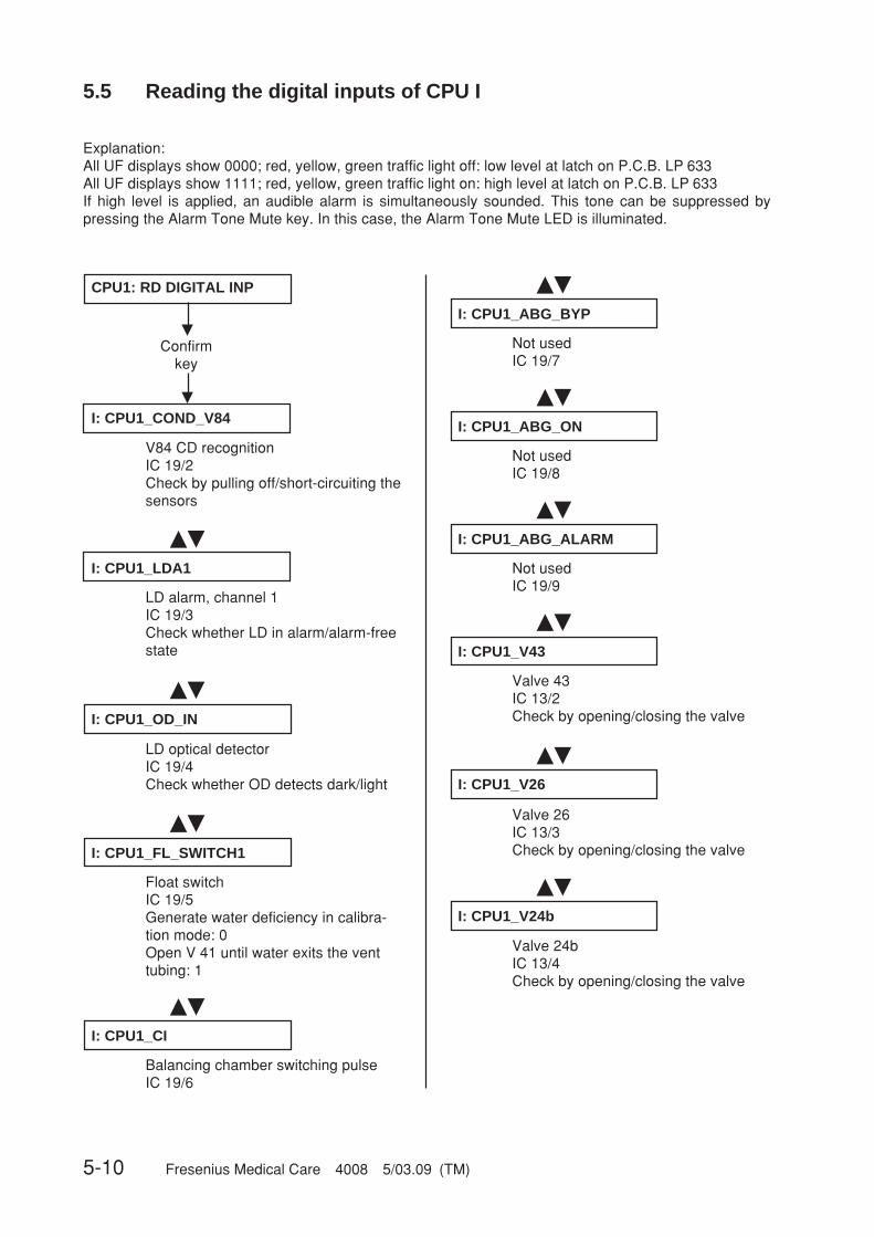
5-10 Fresenius Medical Care 4008 5/03.09 (TM)
�
�
��
��
��
��
��
CPU1: RD DIGITAL INP
Confirmkey
I: CPU1_COND_V84
V84 CD recognitionIC 19/2Check by pulling off/short-circuiting thesensors
I: CPU1_LDA1
LD alarm, channel 1IC 19/3Check whether LD in alarm/alarm-freestate
��
��
��
I: CPU1_OD_IN
LD optical detectorIC 19/4Check whether OD detects dark/light
I: CPU1_FL_SWITCH1
Float switchIC 19/5Generate water deficiency in calibra-tion mode: 0Open V 41 until water exits the venttubing: 1
I: CPU1_CI
Balancing chamber switching pulseIC 19/6
I: CPU1_ABG_BYP
Not usedIC 19/7
I: CPU1_ABG_ON
Not usedIC 19/8
I: CPU1_ABG_ALARM
Not usedIC 19/9
I: CPU1_V43
Valve 43IC 13/2Check by opening/closing the valve
��
I: CPU1_V26
Valve 26IC 13/3Check by opening/closing the valve
��
I: CPU1_V24b
Valve 24bIC 13/4Check by opening/closing the valve
5.5 Reading the digital inputs of CPU I
Explanation:All UF displays show 0000; red, yellow, green traffic light off: low level at latch on P.C.B. LP 633All UF displays show 1111; red, yellow, green traffic light on: high level at latch on P.C.B. LP 633If high level is applied, an audible alarm is simultaneously sounded. This tone can be suppressed bypressing the Alarm Tone Mute key. In this case, the Alarm Tone Mute LED is illuminated.
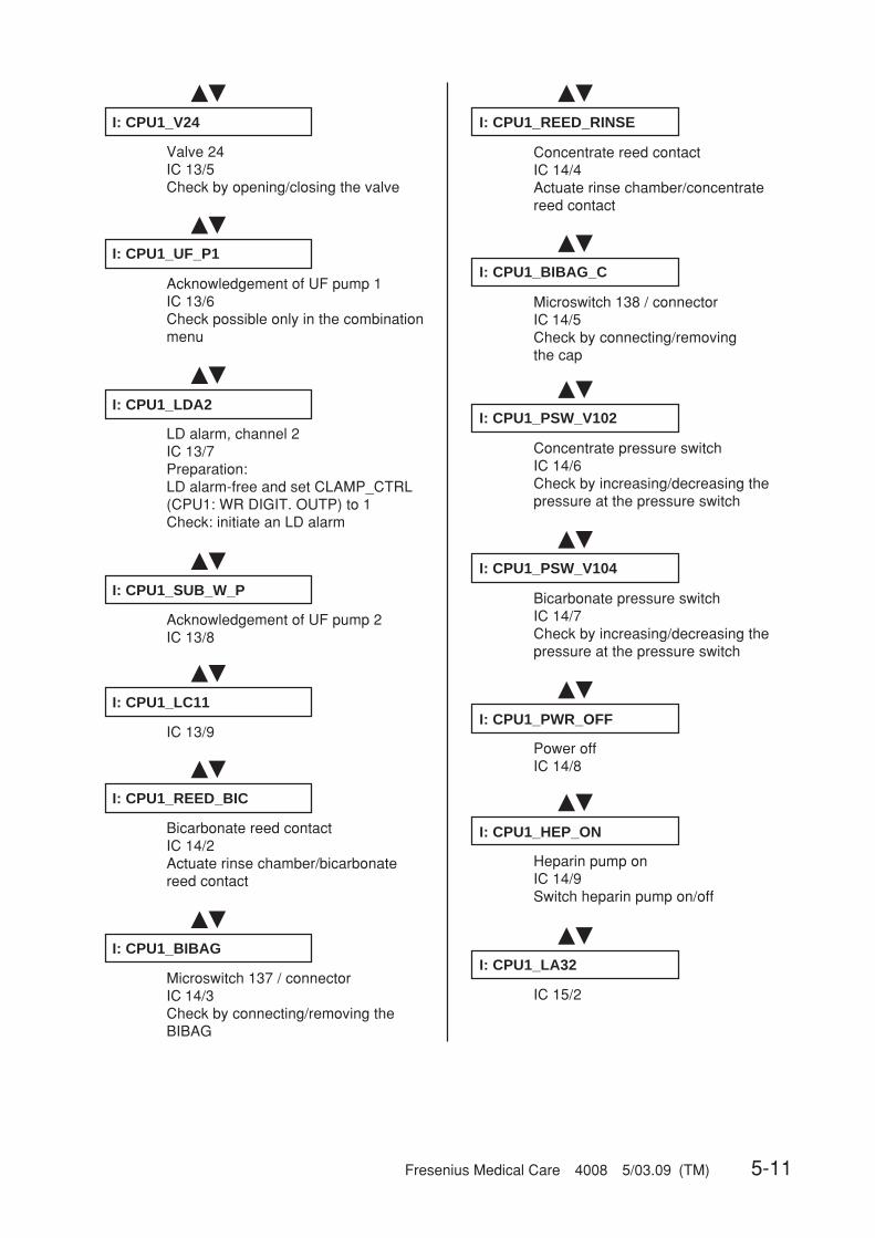
Fresenius Medical Care 4008 5/03.09 (TM) 5-11
�� ��
��
��
��
��
��
��
I: CPU1_V24
Valve 24IC 13/5Check by opening/closing the valve
��
��
I: CPU1_UF_P1
Acknowledgement of UF pump 1IC 13/6Check possible only in the combinationmenu
I: CPU1_LDA2
LD alarm, channel 2IC 13/7Preparation:LD alarm-free and set CLAMP_CTRL(CPU1: WR DIGIT. OUTP) to 1Check: initiate an LD alarm
��
��
��
��
I: CPU1_SUB_W_P
Acknowledgement of UF pump 2IC 13/8
I: CPU1_LC11
IC 13/9
I: CPU1_REED_BIC
Bicarbonate reed contactIC 14/2Actuate rinse chamber/bicarbonatereed contact
I: CPU1_BIBAG
Microswitch 137 / connectorIC 14/3Check by connecting/removing theBIBAG
I: CPU1_REED_RINSE
Concentrate reed contactIC 14/4Actuate rinse chamber/concentratereed contact
I: CPU1_BIBAG_C
Microswitch 138 / connectorIC 14/5Check by connecting/removingthe cap
I: CPU1_PSW_V102
Concentrate pressure switchIC 14/6Check by increasing/decreasing thepressure at the pressure switch
I: CPU1_PSW_V104
Bicarbonate pressure switchIC 14/7Check by increasing/decreasing thepressure at the pressure switch
I: CPU1_PWR_OFF
Power offIC 14/8
I: CPU1_HEP_ON
Heparin pump onIC 14/9Switch heparin pump on/off
I: CPU1_LA32
IC 15/2

5-12 Fresenius Medical Care 4008 5/03.09 (TM)
��
��
��
��
��
��
��
��
��
��
��
��
��
I: CPU1_SW_ON_OFF
On/off key on systemIC 15/3Brief key actuation
I: CPU1_PWR_FAIL
Power failure recognitionIC 15/4
I: CPU1_SHUNT_OUTP
Microswitch, interlock shuntIC 15/5Both lines in the interlock shunt and in-terlock shunt closed: 0
I: CPU1_SHUNT_INP
Microswitch, interlock shuntIC 15/6Red line only in the interlock shunt andinterlock shunt closed: 0
I: CPU1_SHUNT
Microswitch, interlock shuntIC 15/7Open/close interlock shunt
I: CPU1_SERV_EN
Not usedIC 15/8
I: CPU1_LEV_SIGNAL
Level sensor (NTC 6 – replacement)IC 15/9Check by removing/short-circuiting thesensor pins
I: CPU1_SN
Single-Needle changeoverIC 16/2Changeover pressure of SN bloodpump reached: 0
I: CPU1_ADKS
Single-Needle blood pump recognitionconnectedIC 16/3Connect/remove the blood pump (onlywith the system off)
I: CPU1_BPSB_ART
Arterial blood pump stop confirmationIC 16/4Actuation of Start/Stop key on the arte-rial blood pump
I: CPU1_BPUS_ART
Arterial blood pump revolution stopIC 16/5Arterial blood pump alarm field on: 0(cleared by pressing the Start/Stop keyon the blood pump)
I: CPU1_BPSB_VEN
Venous blood pump stop confirmationIC 16/6Actuation of the Start/Stop key on thevenous blood pump
I: CPU1_BPUS_VEN
Venous blood pump revolution stopIC 16/7Preparation:Set SNST (CPU1: WR DIGIT. OUTP)to 1 and wait for the alarm field.Venous blood pump on.Check: clearing of the alarm field bypressing the Start/Stop key on the ve-nous blood pump

Fresenius Medical Care 4008 5/03.09 (TM) 5-13
��
��
��
��
��
��
��
��
��
��
��
��
��
��
��
E. CPU1_HEP_ALARM
Heparin pump alarmIC 16/8Generate a heparin pump alarm(e.g. by blocking the syringe slide)
I: CPU1_BIB_LEVEL
Level sensor 135IC 16/9Check by removing/shorting the sensorpins
I: CPU1_EXT_ALARM
External alarmIC 20/2Release of an external alarm
I: CPU1_SERVICE_MODE
Dialysis/calibration changeoverIC 20/3Reset the service switch
I: CPU1_LEVEL_UP
Raise the LD levelIC 20/4Press the “Raise level” key
I: CPU1_LEVEL_DOWN
Lower the LED levelIC 29/5Preparation:LD alarm-free, set CLAMP_CTRL(CPU1: WR DIGIT. OUTP) to 1Check: press the “Lower level” key
I: CPU1_ADS_SN
Not usedIC 20/6
I: CPU1_ACKN_CONC
Not usedIC 20/7
I: CPU1_ACKN_BIC
Not usedIC 20/8
I: CPU1_BIBAG_PSW
BIBAG pressure switchIC 20/9Check by increasing/decreasing pres-sure on the pressure switch
I: CPU1_RA21
Not usedIC 21/2
HDF onIC 21/3Actuation of HDF On/Off switch
I: CPU1_V102
Acknowledgement, valve 102IC 21/4Open/close the valve
I: CPU1_V104
Acknowledgement, valve 104IC 21/5Open/close the valve
I: CPU1_CSS_REED
IC 21/6
I: CPU1_HDF_ON
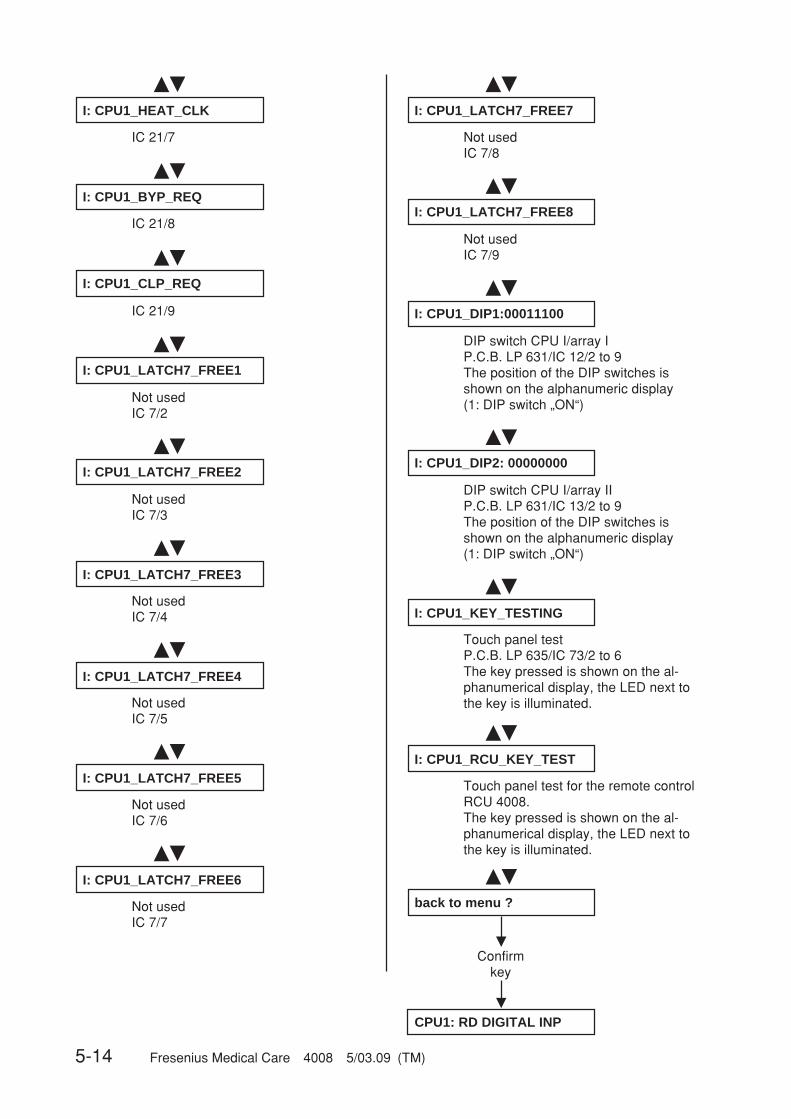
5-14 Fresenius Medical Care 4008 5/03.09 (TM)
��
��
��
��
��
��
��
��
��
��
��
��
I: CPU1_HEAT_CLK
IC 21/7
I: CPU1_BYP_REQ
IC 21/8
I: CPU1_CLP_REQ
IC 21/9
I: CPU1_LATCH7_FREE1
Not usedIC 7/2
I: CPU1_LATCH7_FREE2
I: CPU1_LATCH7_FREE3
Not usedIC 7/4
I: CPU1_LATCH7_FREE4
Not usedIC 7/5
I: CPU1_LATCH7_FREE5
Not usedIC 7/6
I: CPU1_LATCH7_FREE6
Not usedIC 7/7
I: CPU1_LATCH7_FREE7
Not usedIC 7/8
I: CPU1_LATCH7_FREE8
Not usedIC 7/9
I: CPU1_DIP1:00011100
DIP switch CPU I/array IP.C.B. LP 631/IC 12/2 to 9The position of the DIP switches isshown on the alphanumeric display(1: DIP switch „ON“)
��
I: CPU1_DIP2: 00000000
DIP switch CPU I/array IIP.C.B. LP 631/IC 13/2 to 9The position of the DIP switches isshown on the alphanumeric display(1: DIP switch „ON“)
��
��
�
�
I: CPU1_KEY_TESTING
Touch panel testP.C.B. LP 635/IC 73/2 to 6The key pressed is shown on the al-phanumerical display, the LED next tothe key is illuminated.
back to menu ?
Confirmkey
CPU1: RD DIGITAL INP
Not usedIC 7/3
��
I: CPU1_RCU_KEY_TEST
Touch panel test for the remote controlRCU 4008.The key pressed is shown on the al-phanumerical display, the LED next tothe key is illuminated.
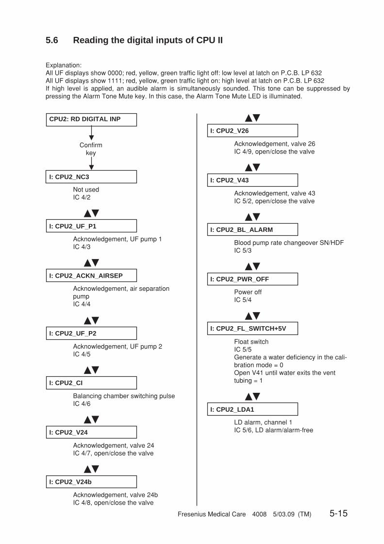
Fresenius Medical Care 4008 5/03.09 (TM) 5-15
�
�
��
��
��
��
��
��
��
��
CPU2: RD DIGITAL INP
Confirmkey
I: CPU2_NC3
Not usedIC 4/2
I: CPU2_UF_P1
Acknowledgement, UF pump 1IC 4/3
I: CPU2_ACKN_AIRSEP
Acknowledgement, air separationpumpIC 4/4
��
��
��
��
I: CPU2_UF_P2
Acknowledgement, UF pump 2IC 4/5
I: CPU2_CI
Balancing chamber switching pulseIC 4/6
I: CPU2_V24
Acknowledgement, valve 24IC 4/7, open/close the valve
I: CPU2_V24b
Acknowledgement, valve 24bIC 4/8, open/close the valve
I: CPU2_V26
Acknowledgement, valve 26IC 4/9, open/close the valve
I: CPU2_V43
Acknowledgement, valve 43IC 5/2, open/close the valve
I: CPU2_BL_ALARM
Blood pump rate changeover SN/HDFIC 5/3
I: CPU2_PWR_OFF
Power offIC 5/4
I: CPU2_FL_SWITCH+5V
Float switchIC 5/5Generate a water deficiency in the cali-bration mode = 0Open V41 until water exits the venttubing = 1
I: CPU2_LDA1
LD alarm, channel 1IC 5/6, LD alarm/alarm-free
5.6 Reading the digital inputs of CPU II
Explanation:All UF displays show 0000; red, yellow, green traffic light off: low level at latch on P.C.B. LP 632All UF displays show 1111; red, yellow, green traffic light on: high level at latch on P.C.B. LP 632If high level is applied, an audible alarm is simultaneously sounded. This tone can be suppressed bypressing the Alarm Tone Mute key. In this case, the Alarm Tone Mute LED is illuminated.

5-16 Fresenius Medical Care 4008 5/03.09 (TM)
��
��
��
I: CPU2_LDA2
LD alarm, channel 2IC 5/7Preparation:LD alarm-free and set CLAMP_CTRL(CPU1: WR DIGIT. OUTP) to 1Check: generate an LD alarm
��
��
��
��
��
I: CPU2_BPSB_VEN
Venous blood pump stop confirmationIC 5/8Actuation of the Start/Stop key on thevenous blood pump
I: CPU2_BPSB_ART
Arterial blood pump stop confirmationIC 5/9Actuation of the Start/Stop key on thearterial blood pump
I: CPU2_V42
Not usedIC 6/2
I: CPU2_BPST_ART
Acknowledgement, special control ofthe arterial blood pumpIC 6/3Check by setting BPST_ART(CPU1: WR DIGIT. OUTP) to 1/0
I: CPU2_BPUS_ART
Arterial blood pump revolution stopIC 6/4Alarm field of the arterial blood pumpon = 0(cleared by pressing the Start/Stop keyon the blood pump)
I: CPU2_BPST_VEN
Acknowledgement, special control ofthe venous blood pumpIC 6/5Check by setting BPST_VEN(CPU1: WR DIGIT. OUTP) to 1/0
I: CPU2_BPUS_VEN
Venous blood pump revolution stopIC 6/6Preparation:Set SNST (CPU1: WR DIGIT. OUTP)to 1 and wait for the alarm field of thevenous blood pump to turn onCheck: clear the alarm field by press-ing the Start/Stop key on the venousblood pump
��
��
��
I: CPU2_ADKS
Single-Needle blood pump recognitionconnectedIC 6/7Connect/remove the blood pump (withthe system off only)
I: CPU2_LEVEL_UP
Raise LD levelIC 6/8, press the “Raise level” key
I: CPU2_LEVEL_DOWN
Lower LD levelIC 6/9Preparation:LD alarm-free, set CLAMP_CTRL(CPU1: WR DIGIT. OUTP) to 1Check: press the “Lower level” key
��
I: CPU2_RINSE
Concentrate reed contactIC 7/2Actuate rinse chamber/concentratereed contact
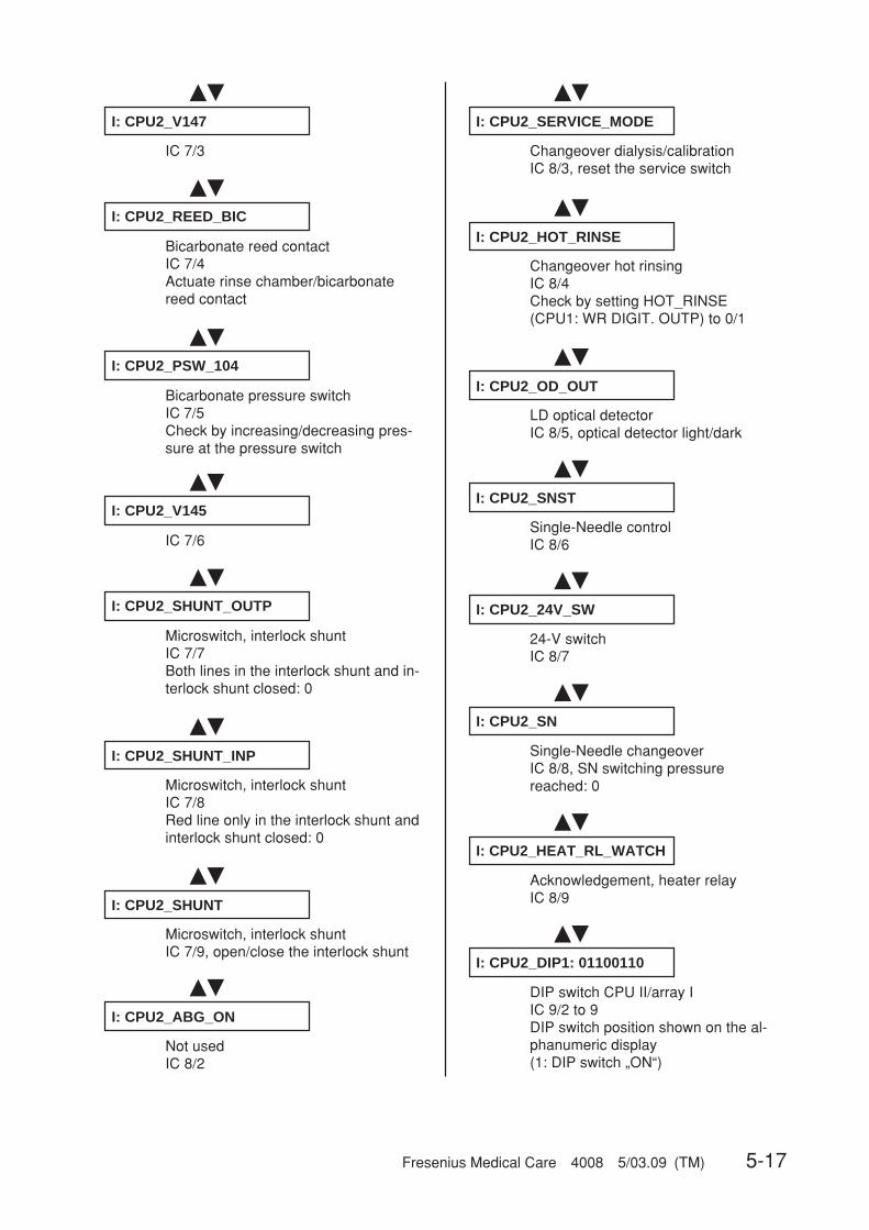
Fresenius Medical Care 4008 5/03.09 (TM) 5-17
��
��
��
��
��
��
��
��
��
��
��
I: CPU2_V147
IC 7/3
I: CPU2_REED_BIC
Bicarbonate reed contactIC 7/4Actuate rinse chamber/bicarbonatereed contact
I: CPU2_PSW_104
Bicarbonate pressure switchIC 7/5Check by increasing/decreasing pres-sure at the pressure switch
I: CPU2_V145
IC 7/6
I: CPU2_SHUNT_OUTP
Microswitch, interlock shuntIC 7/7Both lines in the interlock shunt and in-terlock shunt closed: 0
I: CPU2_SHUNT_INP
Microswitch, interlock shuntIC 7/8Red line only in the interlock shunt andinterlock shunt closed: 0
I: CPU2_SHUNT
Microswitch, interlock shuntIC 7/9, open/close the interlock shunt
I: CPU2_ABG_ON
Not usedIC 8/2
I: CPU2_SERVICE_MODE
Changeover dialysis/calibrationIC 8/3, reset the service switch
I: CPU2_HEAT_RL_WATCH
Acknowledgement, heater relayIC 8/9
I: CPU2_DIP1: 01100110
DIP switch CPU II/array IIC 9/2 to 9DIP switch position shown on the al-phanumeric display(1: DIP switch „ON“)
��
��
��
��
��
I: CPU2_HOT_RINSE
Changeover hot rinsingIC 8/4Check by setting HOT_RINSE(CPU1: WR DIGIT. OUTP) to 0/1
I: CPU2_OD_OUT
LD optical detectorIC 8/5, optical detector light/dark
I: CPU2_SNST
Single-Needle controlIC 8/6
I: CPU2_24V_SW
24-V switchIC 8/7
I: CPU2_SN
Single-Needle changeoverIC 8/8, SN switching pressurereached: 0
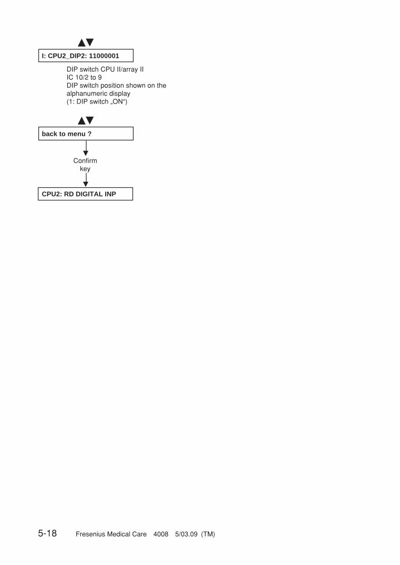
5-18 Fresenius Medical Care 4008 5/03.09 (TM)
��
��
�
�
I: CPU2_DIP2: 11000001
DIP switch CPU II/array IIIC 10/2 to 9DIP switch position shown on thealphanumeric display(1: DIP switch „ON“)
back to menu ?
Confirmkey
CPU2: RD DIGITAL INP
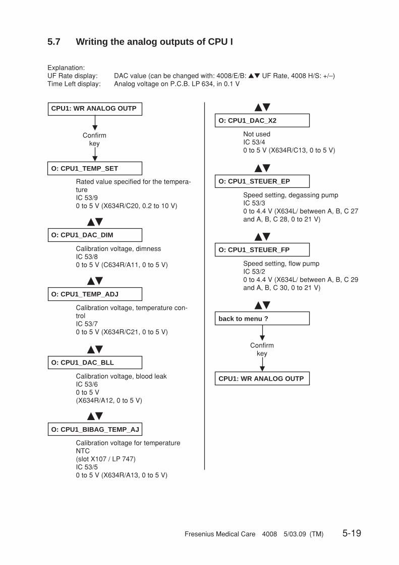
Fresenius Medical Care 4008 5/03.09 (TM) 5-19
�
�
��
��
��
��
�
�
CPU1: WR ANALOG OUTP
Confirmkey
O: CPU1_TEMP_SET
Rated value specified for the tempera-tureIC 53/90 to 5 V (X634R/C20, 0.2 to 10 V)
��
��
��
��
O: CPU1_DAC_DIM
Calibration voltage, dimnessIC 53/80 to 5 V (C634R/A11, 0 to 5 V)
O: CPU1_TEMP_ADJ
Calibration voltage, temperature con-trolIC 53/70 to 5 V (X634R/C21, 0 to 5 V)
O: CPU1_DAC_BLL
Calibration voltage, blood leakIC 53/60 to 5 V(X634R/A12, 0 to 5 V)
O: CPU1_BIBAG_TEMP_AJ
Calibration voltage for temperatureNTC(slot X107 / LP 747)IC 53/50 to 5 V (X634R/A13, 0 to 5 V)
O: CPU1_DAC_X2
Not usedIC 53/40 to 5 V (X634R/C13, 0 to 5 V)
O: CPU1_STEUER_EP
Speed setting, degassing pumpIC 53/30 to 4.4 V (X634L/ between A, B, C 27and A, B, C 28, 0 to 21 V)
O: CPU1_STEUER_FP
Speed setting, flow pumpIC 53/20 to 4.4 V (X634L/ between A, B, C 29and A, B, C 30, 0 to 21 V)
back to menu ?
Confirmkey
CPU1: WR ANALOG OUTP
5.7 Writing the analog outputs of CPU I
Explanation:UF Rate display: DAC value (can be changed with: 4008/E/B: ▲▼ UF Rate, 4008 H/S: +/–)Time Left display: Analog voltage on P.C.B. LP 634, in 0.1 V

5-20 Fresenius Medical Care 4008 5/03.09 (TM)
�
�
��CPU2: WR ANALOG OUTP
Confirmkey
O: CPU2_TEMP_DET_ADJ
Detuning, temperature displayIC 11/2, 0 to 10 V (X632/A23, 0 to10 V)
��
O: CPU2_DIAL_DET_ADJ
Detuning, dialysate pressure displayIC 11/1, 0 to 10 V (X632/C 20, 0 to10 V)
��
O: CPU2_P_ADS_DET
Not usedIC 11/20, 0 to 10 V (X632/A 20, 0 to10 V)
��
O: CPU2_PV_DET
Detuning, venous pressureIC 11/20, 0 to 10 V (X632/C 18, 1 to9 V)
��
O: CPU2_PA_DET
Detuning, arterial pressureIC 11/19, 0 to 10 V (X632/A 17, 4 to7 V)
��
O: CPU2_COND_DET
Detuning, CD displayIC 11/19, 0 to 10 V (X632/A 21, 0 to10 V)
O: CPU2_HIGH_RES_OP
OP control voltagefor higher resolution of dialysate pres-sureIC 11/20, 0 to 10 V
��
�
�
back to menu ?
Confirmkey
CPU2: WR ANALOG OUTP
5.8 Writing the analog outputs of CPU II
Explanation:UF Rate display: DAC value (can be changed with: 4008/E/B: ▲▼ UF Rate, 4008 H/S: +/–)Time Left display: Analog voltage on P.C.B. LP 632, in 0.1 V

Fresenius Medical Care 4008 5/03.09 (TM) 5-21
�
�
��
��
��
��
��
��
��
��
��
��
��
��
CPU1: WR DIGIT. OUTP
Confirmkey
O: CPU1_V24
Valve 24IC 10/19
O: CPU1_V24b
Valve 24bIC 10/13
O: CPU1_V26
Valve 26IC 10/18
O: CPU1_V130
Valve 130IC 10/17
O: CPU1_V30
Valve 30IC 7/16
O: CPU1_V31
Valve 31IC 12/19
O: CPU1_V32
Valve 32IC 12/18
O: CPU1_V33
Valve 33IC 12/17
O: CPU1_V34
Valve 34IC 12/16
O: CPU1_V35
Valve 35IC 12/15
O: CPU1_V36
Valve 36IC 12/14
O: CPU1_V37
Valve 37IC 12/13
O: CPU1_V38
Valve 38IC 12/12
5.9 Writing the digital outputs of CPU I
Explanation:UF Rate display: 0000 = not active
1111 = active (P.C.B. LP 634 level) (can be changed with: 4008/E/B: ▲▼ UF Rate, 4008 H/S: +/–)
��
O: CPU1_V41
Valve 41IC 7/13(After a short time interval, the valvecloses automatically, to prevent thewater from overflowing.)
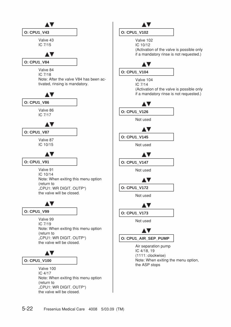
5-22 Fresenius Medical Care 4008 5/03.09 (TM)
��
��
O: CPU1_V43
Valve 43IC 7/15
O: CPU1_V84
Valve 84IC 7/18Note: After the valve V84 has been ac-tivated, rinsing is mandatory.
��
��
��
��
O: CPU1_V86
Valve 86IC 7/17
O: CPU1_V87
Valve 87IC 10/15
O: CPU1_V91
Valve 91IC 10/14Note: When exiting this menu option(return to„CPU1: WR DIGIT. OUTP“)the valve will be closed.
O: CPU1_V99
Valve 99IC 7/19Note: When exiting this menu option(return to„CPU1: WR DIGIT. OUTP“)the valve will be closed.
��
O: CPU1_V100
Valve 100IC 4/17Note: When exiting this menu option(return to„CPU1: WR DIGIT. OUTP“)the valve will be closed.
��
��
O: CPU1_V102
Valve 102IC 10/12(Activation of the valve is possible onlyif a mandatory rinse is not requested.)
O: CPU1_V104
Valve 104IC 7/14(Activation of the valve is possible onlyif a mandatory rinse is not requested.)
Not used
��
O: CPU1_V126
Not used
��
O: CPU1_V145
Not used
��
O: CPU1_V147
Not used
��
O: CPU1_V172
Not used
��
O: CPU1_V173
��
O: CPU1_AIR_SEP_PUMP
Air separation pumpIC 4/18, 19(1111: clockwise)Note: When exiting the menu option,the ASP stops
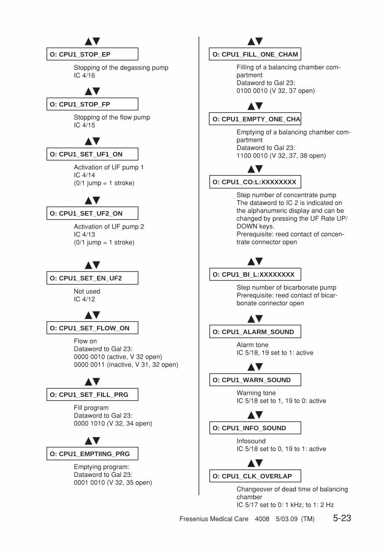
Fresenius Medical Care 4008 5/03.09 (TM) 5-23
��
��
��
��
��
O: CPU1_BI_L:XXXXXXXX
Step number of bicarbonate pumpPrerequisite: reed contact of bicar-bonate connector open
O: CPU1_ALARM_SOUND
Alarm toneIC 5/18, 19 set to 1: active
O: CPU1_WARN_SOUND
Warning toneIC 5/18 set to 1, 19 to 0: active
O: CPU1_INFO_SOUND
InfosoundIC 5/18 set to 0, 19 to 1: active
O: CPU1_CLK_OVERLAP
Changeover of dead time of balancingchamberIC 5/17 set to 0: 1 kHz; to 1: 2 Hz
��
O: CPU1_CO:L:XXXXXXXX
Step number of concentrate pumpThe dataword to IC 2 is indicated onthe alphanumeric display and can bechanged by pressing the UF Rate UP/DOWN keys.Prerequisite: reed contact of concen-trate connector open
��
��
��
O: CPU1_STOP_EP
Stopping of the degassing pumpIC 4/16
O: CPU1_STOP_FP
Stopping of the flow pumpIC 4/15
O: CPU1_SET_UF1_ON
Activation of UF pump 1IC 4/14(0/1 jump = 1 stroke)
��
��
��
��
O: CPU1_SET_EN_UF2
Not usedIC 4/12
O: CPU1_SET_FLOW_ON
Flow onDataword to Gal 23:0000 0010 (active, V 32 open)0000 0011 (inactive, V 31, 32 open)
O: CPU1_SET_FILL_PRG
Fill programDataword to Gal 23:0000 1010 (V 32, 34 open)
O: CPU1_EMPTIING_PRG
Emptying program:Dataword to Gal 23:0001 0010 (V 32, 35 open)
��
O: CPU1_SET_UF2_ON
Activation of UF pump 2IC 4/13(0/1 jump = 1 stroke)
��
��
O: CPU1_FILL_ONE_CHAM
Filling of a balancing chamber com-partmentDataword to Gal 23:0100 0010 (V 32, 37 open)
O: CPU1_EMPTY_ONE_CHA
Emptying of a balancing chamber com-partmentDataword to Gal 23:1100 0010 (V 32, 37, 38 open)
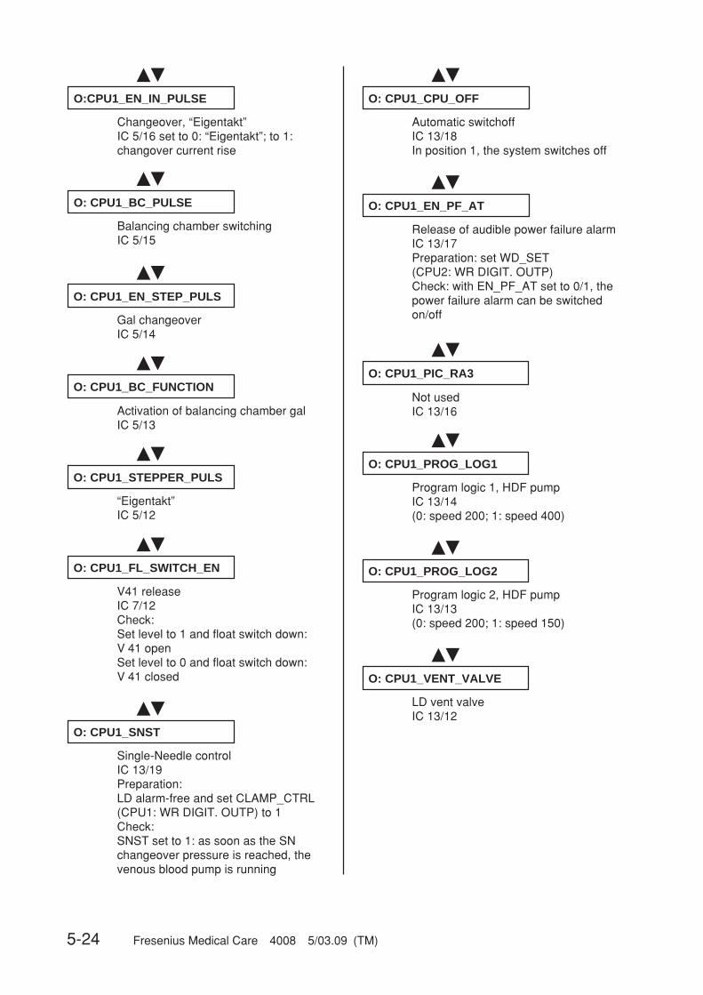
5-24 Fresenius Medical Care 4008 5/03.09 (TM)
��
��
��
��
O: CPU1_BC_FUNCTION
Activation of balancing chamber galIC 5/13
O: CPU1_STEPPER_PULS
“Eigentakt”IC 5/12
O: CPU1_FL_SWITCH_EN
V41 releaseIC 7/12Check:Set level to 1 and float switch down:V 41 openSet level to 0 and float switch down:V 41 closed
O: CPU1_SNST
Single-Needle controlIC 13/19Preparation:LD alarm-free and set CLAMP_CTRL(CPU1: WR DIGIT. OUTP) to 1Check:SNST set to 1: as soon as the SNchangeover pressure is reached, thevenous blood pump is running
��
O: CPU1_EN_STEP_PULS
Gal changeoverIC 5/14
��
��
O:CPU1_EN_IN_PULSE
Changeover, “Eigentakt”IC 5/16 set to 0: “Eigentakt”; to 1:changover current rise
O: CPU1_BC_PULSE
Balancing chamber switchingIC 5/15
��
O: CPU1_EN_PF_AT
Release of audible power failure alarmIC 13/17Preparation: set WD_SET(CPU2: WR DIGIT. OUTP)Check: with EN_PF_AT set to 0/1, thepower failure alarm can be switchedon/off
��
O: CPU1_CPU_OFF
Automatic switchoffIC 13/18In position 1, the system switches off
��
��
��
��
O: CPU1_PIC_RA3
Not usedIC 13/16
O: CPU1_PROG_LOG1
Program logic 1, HDF pumpIC 13/14(0: speed 200; 1: speed 400)
O: CPU1_PROG_LOG2
Program logic 2, HDF pumpIC 13/13(0: speed 200; 1: speed 150)
O: CPU1_VENT_VALVE
LD vent valveIC 13/12
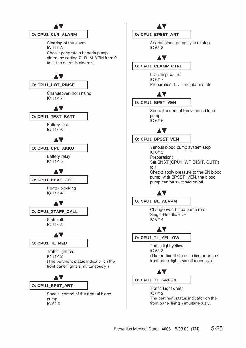
Fresenius Medical Care 4008 5/03.09 (TM) 5-25
��
��
O: CPU1_CLAMP_CTRL
LD clamp controlIC 6/17Preparation: LD in no alarm state
O: CPU1_BPST_VEN
Special control of the venous bloodpumpIC 6/16
��
��
��
O: CPU1_BPSST_VEN
Venous blood pump system stopIC 6/15Preparation:Set SNST (CPU1: WR DIGIT. OUTP)to 1Check: apply pressure to the SN bloodpump; with BPSST_VEN, the bloodpump can be switched on/off.
O: CPU1_BL_ALARM
Changeover, blood pump rateSingle-Needle/HDFIC 6/14
O: CPU1_TL_YELLOW
Traffic light yellowIC 6/13(The pertinent status indicator on thefront panel lights simultaneously.)
��
O: CPU1_TL_GREEN
Traffic Light greenIC 6/12The pertinent status indicator on thefront panel lights simultaneously.
��
��
��
��
��
��
O: CPU1_HOT_RINSE
Changeover, hot rinsingIC 11/17
O: CPU1_TEST_BATT
Battery testIC 11/16
O: CPU1_CPU_AKKU
Battery relayIC 11/15
O: CPU1_HEAT_OFF
Heater blockingIC 11/14
O: CPU1_STAFF_CALL
Staff callIC 11/13
O: CPU1_TL_RED
Traffic light redIC 11/12(The pertinent status indicator on thefront panel lights simultaneously.)
��
O: CPU1_BPST_ART
Special control of the arterial bloodpumpIC 6/19
��
O: CPU1_CLR_ALARM
Clearing of the alarmIC 11/18Check: generate a heparin pumpalarm; by setting CLR_ALARM from 0to 1, the alarm is cleared.
��
O: CPU1_BPSST_ART
Arterial blood pump system stopIC 6/18
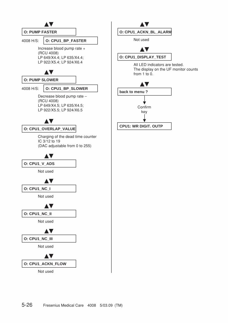
5-26 Fresenius Medical Care 4008 5/03.09 (TM)
��
O: CPU1_OVERLAP_VALUE
Charging of the dead time counterIC 3/12 to 19(DAC adjustable from 0 to 255)
Decrease blood pump rate –(RCU 4008)LP 649/X4.5; LP 635/X4.5;LP 922/X5.5; LP 924/X6.5
��
O: PUMP SLOWER
Increase blood pump rate +(RCU 4008)LP 649/X4.4; LP 635/X4.4;LP 922/X5.4; LP 924/X6.4
��
O: PUMP FASTER
O: CPU1_BP_SLOWER
O: CPU1_BP_FASTER4008 H/S:
4008 H/S:
��
��
�
�
All LED indicators are tested.The display on the UF monitor countsfrom 1 to 0.
O: CPU1_DISPLAY_TEST
back to menu ?
Confirmkey
CPU1: WR DIGIT. OUTP
Not used
��
O: CPU1_V_ADS
Not used
��
O: CPU1_NC_I
Not used
��
O: CPU1_NC_II
Not used
��
O: CPU1_NC_III
Not used
��
O: CPU1_ACKN_FLOW
Not used
��
O: CPU1_ACKN_BL_ALARM

Fresenius Medical Care 4008 5/03.09 (TM) 5-27
�
�
CPU2: WR DIGIT. OUTP
Confirmkey
O: CPU2_WD_RES
Watchdog resetIC 24/18Preparation:Set WD_SET (CPU2: WR DIGIT.OUTP) to 0, then to 1 again.Check:Briefly set WD_RES to 0; upon reset to1, the WD relay is connected.
��
O: CPU2_WD_SET
Watchdog setIC 24/17Watchdog relay drops out, 24 Vswitched off, audible signal is sounded.To clear the alarm, turn the system offand on again.Otherwise calibration impossible.
5.10 Writing the digital outputs of CPU II
Explanation:UF Rate display: 0000 = not active
1111 = active (P.C.B. LP 632 level)(can be changed with: 4008/E/B: ▲▼ UF Rate, 4008 H/S: +/–)
��
��
O: CPU2_V24_EN
Release of V 24IC 24/16Preparation: V 24Switch on (CPU1: WR DIGIT. OUTP).Check: switch the valve on/off withV 24_EN.
O: CPU2_V24B_EN
Release of V24bIC 24/15Preparation: switch on V 24B(CPU1: WR DIGIT. OUTP).Check: switch the valve on/off withV 24B_EN.
��
O: CPU2_UF_P_CTRL
Activation of UF pumpIC 24/14, 0/1 level change = 1 strokePreparation: set CPU2_UF_P_ENto 1.
��
��
��
��
��
O: CPU2_UF_P_EN
Release of UF pumpsIC 24/13
O: CPU2_CPU2_ALARM
Release of the alarm tone by CPU IIIC 24/12
O: CPU2_UF_P2_CTRL
Activation of UF-Pump 2IC 24/11, 0/1 level change = 1 strokePreparation: set CPU2_UF_P_ENto 1.
��
O: CPU2_4066_ENABLE_1
Analog switch for P_ADS_DETIC 20/13 (X632/A20)
O: CPU2_4066_ENABLE_2
Analog switch for +10-V reference volt-ageIC 27/5
O: CPU2_4066_ENABLE_3
Analog switch for PV_DETIC 20/6 (X632/C18)

5-28 Fresenius Medical Care 4008 5/03.09 (TM)
��
��
O: CPU2_NC7
Not usedX632/B10
O: CPU2_BLL_DET
Detuning of blood leak detectorX632/A25
��
O: CPU2_4066_ENABLE_4
Analog switch for PA_DETIC 20/12 (X632/A17)
��
O: CPU2_4066_ENABLE_5
Analog switch, not usedIC 27/13
��
��
��
��
��
��
O: CPU2_4066_ENABLE_6
Analog switch for COND_DETIC 20/5 (X632/A21)
O: CPU2_4066_ENABLE_7
Analog switch for BLL_DIMIC 27/6
O: CPU2_4066_ENABLE_8
Analog switch for BLLIC 27/12
O: CPU2_SN_ART
Single-Needle control, arterialX632/A15
O: CPU2_LDSA
Attenuation of LD ultrasonic sensorX632/C16Preparation:LD alarm-free and set CLAMP_CTRL(CPU1: WR DIGIT. OUTP) to 1.Check: by setting LDSA to 1, theclamp at the LD closes.
O: CPU2_ODSA
Attenuation of LD optical sensorX632/C15
��
��
��
��
��
O: CPU2_SN_EN
Release of Single-NeedleX632/C19
O: CPU2_NC10
Not usedX632/B4
O: CPU2_V26
Valve 26X632/A6
O: CPU2_V42
Not usedX632/C4
O: CPU2_V43
Valve 43X632/C5
��
��
O: CPU2_CLAMP_CTRL
Clamp control, air detectorX632/C10Preparation: LD in no alarm state
O: CPU2_NC5
Not usedX632/B25
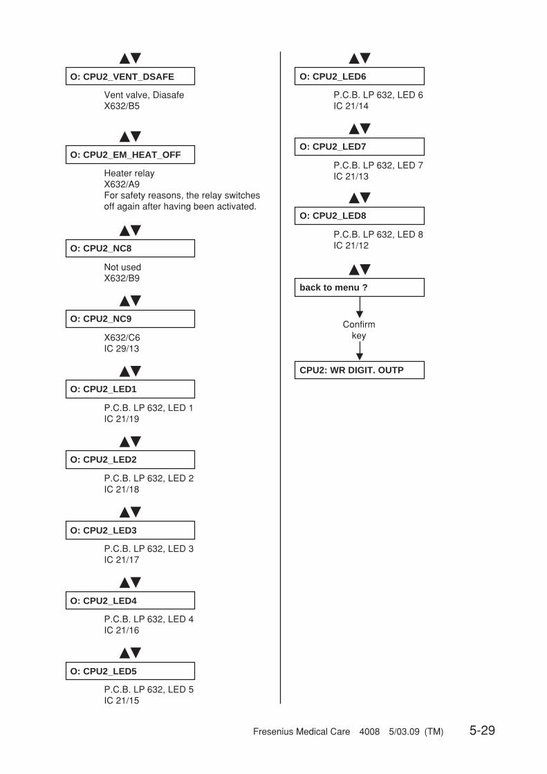
Fresenius Medical Care 4008 5/03.09 (TM) 5-29
��
��
��
�
�
��
O: CPU2_LED6
P.C.B. LP 632, LED 6IC 21/14
O: CPU2_LED7
P.C.B. LP 632, LED 7IC 21/13
O: CPU2_LED8
P.C.B. LP 632, LED 8IC 21/12
back to menu ?
Confirmkey
CPU2: WR DIGIT. OUTP
��
��
��
��
��
��
��
��
O: CPU2_EM_HEAT_OFF
Heater relayX632/A9For safety reasons, the relay switchesoff again after having been activated.
O: CPU2_NC8
Not usedX632/B9
O: CPU2_NC9
X632/C6IC 29/13
O: CPU2_LED1
P.C.B. LP 632, LED 1IC 21/19
O: CPU2_LED2
P.C.B. LP 632, LED 2IC 21/18
O: CPU2_LED3
P.C.B. LP 632, LED 3IC 21/17
O: CPU2_LED4
P.C.B. LP 632, LED 4IC 21/16
O: CPU2_LED5
P.C.B. LP 632, LED 5IC 21/15
��
O: CPU2_VENT_DSAFE
Vent valve, DiasafeX632/B5

5-30 Fresenius Medical Care 4008 5/03.09 (TM)
�
�
��CPU1: COMBINATION
Confirmkey
CPU 1_COMBI: V24
Valve 24Activation, P.C.B. LP 634/IC 10/19Acknowledgement, P.C.B. LP 633/IC 13/5
��
CPU 1_COMBI: V24b
Valve 24bActivation, P.C.B. LP 634/IC 10/13Acknowledgement, P.C.B. LP 633/IC 13/4
��
CPU 1_COMBI: V26
Valve 26Activation, P.C.B. LP 634/IC 10/18Acknowledgement, P.C.B. LP 633/IC 13/3
��
CPU 1_COMBI: V43
Valve 43Activation, P.C.B. LP 634/IC 7/15Acknowledgement, P.C.B. LP 633/IC 13/2
��
CPU 1_COMBI: V102
Valve 102Activation, P.C.B. LP 634/IC 10/12Acknowledgement, P.C.B. LP 633/IC 21/4(Activation of the valve is possible onlyif a mandatory rinse is not requested)
CPU 1_COMBI: V104
Valve 104Activation, P.C.B. LP 634/IC 7/14Acknowledgement, P.C.B. LP 633/IC21/5(Activation of the valve is possible onlyif a mandatory rinse is not requested)
��
��
��
�
�
CPU 1_COMBI: UF1_PUMP
UF pump 1Activation, P.C.B. LP 634/IC 4/14Acknowledgement, P.C.B. LP 633/IC13/6(when setting from 0 to 1 = 1 stroke;acknowledgement is a brief change to1)
CPU 1_COMBI: AIR_SEP
Switching the ASP on/off
back to menu ?
Confirmkey
CPU 1: COMBINATION
5.11 Writing/Reading the digital outputs of CPU I
Explanation:UF Volume display: Acknowledgement/input (in case of 1111, the three status LEDs of the traffic light
are also illuminated)UF Rate display: Activation/output (can be changed with: 4008/E/B: ▲▼ UF Rate, 4008 H/S: +/–)

Fresenius Medical Care 4008 5/03.09 (TM) 5-31
5.12 ONLINEplusplusplusplusplus™ module
▲▼
▲▼
▲▼
▲▼
▲▼
▲▼
▲▼
▲▼
▲▼
▲▼
▲▼
▲▼
ONLINE-PLUS-MODUL
Confirmkey
READ INPUTS Confirmkey
WRITE OUTPUTS Confirmkey
back to menu ? Confirmkey
WRITE ANALOG OUTPUTS Confirmkey
WRITE DIGITAL OUTPUTS Confirmkey
back to menu ? Confirmkey
READ ANALOG INPUTS Confirmkey
READ DIGITAL INPUTS Confirmkey
back to menu ? Confirmkey
not yet implemented
A: ONL+_ONL1 (V193)
P.C.B. LP 785 X1/6avalve Online 1 V193
A: ONL+_ONL2 (V192)
P.C.B. LP 785 X1/7avalve Online 2 V192
A: ONL+_ONL3 (V191)
P.C.B. LP 785 X1/8avalve Online 3 V191
back to menu ? Confirmkey
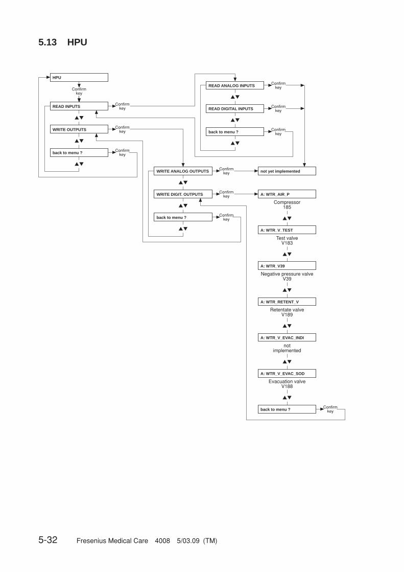
5-32 Fresenius Medical Care 4008 5/03.09 (TM)
5.13 HPU
HPU
Confirmkey
READ INPUTS Confirmkey
WRITE OUTPUTS Confirmkey
back to menu ? Confirmkey
WRITE ANALOG OUTPUTS Confirmkey
WRITE DIGIT. OUTPUTS Confirmkey
back to menu ? Confirmkey
READ ANALOG INPUTS Confirmkey
READ DIGITAL INPUTS Confirmkey
back to menu ? Confirmkey
not yet implemented
back to menu ? Confirmkey
A: WTR_AIR_P
Compressor 185
A: WTR_V_TEST
Test valveV183
A: WTR_V39
Negative pressure valveV39
A: WTR_RETENT_V
Retentate valveV189
A: WTR_V_EVAC_INDI
notimplemented
A: WTR_V_EVAC_SOD
Evacuation valveV188
▲▼
▲▼
▲▼
▲▼
▲▼
▲▼
▲▼
▲▼
▲▼
▲▼
▲▼
▲▼
▲▼
▲▼
▲▼
Fresenius Medical Care 4008 5/03.09 (TM) 6-1
Table of contents6 Setup menu
Section Page
6.1 Overview Setup menu settings ................................................................................... 6-3
6.2 Overview ........................................................................................................................ 6-7
6.3 Main menu 4008 E/B ..................................................................................................... 6-9
6.4 Main menu 4008 H/S ..................................................................................................... 6-37

6-2 Fresenius Medical Care 4008 5/03.09 (TM)
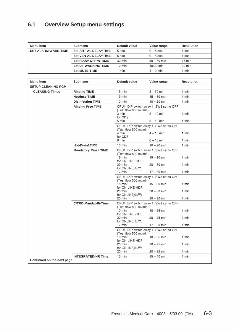
Fresenius Medical Care 4008 5/03.09 (TM) 6-3
6.1 Overview Setup menu settings
Menu item Submenu Default value Value range Resolution
SET ALARM/WARN TIME Set ART-AL DELAYTIME 5 sec 0 – 5 sec 1 sec
Set VEN-AL DELAYTIME 5 sec 0 – 5 sec 1 sec
Set FLOW-OFF W-TIME 30 min 30 – 60 min 15 min
Set UF-WARNING-TIME 10 min 10/30 min 20 min
Set MUTE-TIME 1 min 1 – 2 min 1 min
Menu item Submenu Default value Value range Resolution
SETUP CLEANING PGM
CLEANING Times Rinsing TIME 15 min 5 – 30 min 1 min
Hotrinse TIME 15 min 15 – 30 min 1 min
Disinfection TIME 10 min 10 – 20 min 1 min
Rinsing Free TIME CPU1: DIP switch array 1, SW8 set to OFF(Test flow 800 ml/min)3 min 3 – 10 min 1 minfor CDS:5 min 5 – 10 min 1 min
CPU1: DIP switch array 1, SW8 set to ON(Test flow 500 ml/min)4 min 4 – 10 min 1 minfor CDS:6 min 6 – 10 min 1 min
Hot-Disinf TIME 10 min 10 – 20 min 1 min
Mandatory Rinse TIME CPU1: DIP switch array 1, SW8 set to OFF(Test flow 800 ml/min)15 min 15 – 30 min 1 minfor ON-LINE-HDF:20 min 20 – 30 min 1 minfor ONLINEplus™:17 min 17 – 30 min 1 min
CPU1: DIP switch array 1, SW8 set to ON(Test flow 500 ml/min)15 min 15 – 30 min 1 minfor ON-LINE-HDF:20 min 20 – 30 min 1 minfor ONLINEplus™:20 min 20 – 30 min 1 min
CITRO-Mandat-Ri-Time CPU1: DIP switch array 1, SW8 set to OFF(Test flow 800 ml/min)10 min 10 – 25 min 1 minfor ON-LINE-HDF:20 min 20 – 25 min 1 minfor ONLINEplus™:17 min 17 – 25 min 1 min
CPU1: DIP switch array 1, SW8 set to ON(Test flow 500 ml/min)10 min 10 – 25 min 1 minfor ON-LINE-HDF:20 min 20 – 25 min 1 minfor ONLINEplus™:20 min 20 – 25 min 1 min
INTEGRATED-HR Time 15 min 15 – 40 min 1 minContinued on the next page

6-4 Fresenius Medical Care 4008 5/03.09 (TM)
Menu item Submenu Default value Selectable options
SETUP CLEANING PGM(Continued)
Pgm COMBINATION RINSE Pgm PGM 1: –R– PGM 1: –R–only for 4008 E/B PGM 2: –R– endless
HOTRINSE Program PGM 1: –F–HR–C– PGM 1: –F–HR–C–PGM 2: –F–HR–PGM 3: –IHR–PGM 4: –IHR–C–
DISINFECTION Pgm PGM 2: –F–HDIS–M– PGM 1: –F–D–M–PGM 2: –F–HDIS–M–PGM 3: –F–D–M–HR–PGM 4: –F–HDIS–M–HR–
DEFAULT Cleaning Pgm PGM 1: –R– PGM 1: –R–only for 4008 E/B PGM 2: –R– endless
PGM 1: –F–HR–C–PGM 2: –F–HR–PGM 3: –IHR–PGM 4: –IHR–C–PGM 1: –F–D–M–PGM 2: –F–HDIS–M–PGM 3: –F–D–M–HR–PGM 4: –F–HDIS–M–HR–
Menu item Submenu Default value Selectable options
SETUP DILUTION canister canister 1+34 canister 1+341+35.83 ( NaCl 20 )1+35.83 ( NaCl 26 )1+35.83 ( Belgium )canister 1+44 Ccanister 1+44 ACFVARIABLE SETTING
CDS CDS 1+34 CDS 1+34CDS 1+44 CCDS 1+44 ACF
Default value Value range Resolution
VARIABLE SETTING – 0.800 – 2.500 0.001– 30.000 – 45.000 0.001– 25 – 45 1– 25 – 80 1
Menu item Submenu Default value Selectable options
HDF-DILUTION HDF–PRE–dilution HDF–PRE–dilutiononly for ON-LINE-HDF (option) HDF–POST–dilution
Menu item Submenu Default value Value range Resolution
SET CONDUCT. LIMIT Cd Limit: 12.8 mS/cm 12.8 mS/cm 12.8 – 14.0 mS/cm 0.1 mS/cm
Menu item Submenu Default value Selectable options
INFO SOUND ( C-PGM ) Info-Sound: ON Info-Sound: ONInfo-Sound: OFF
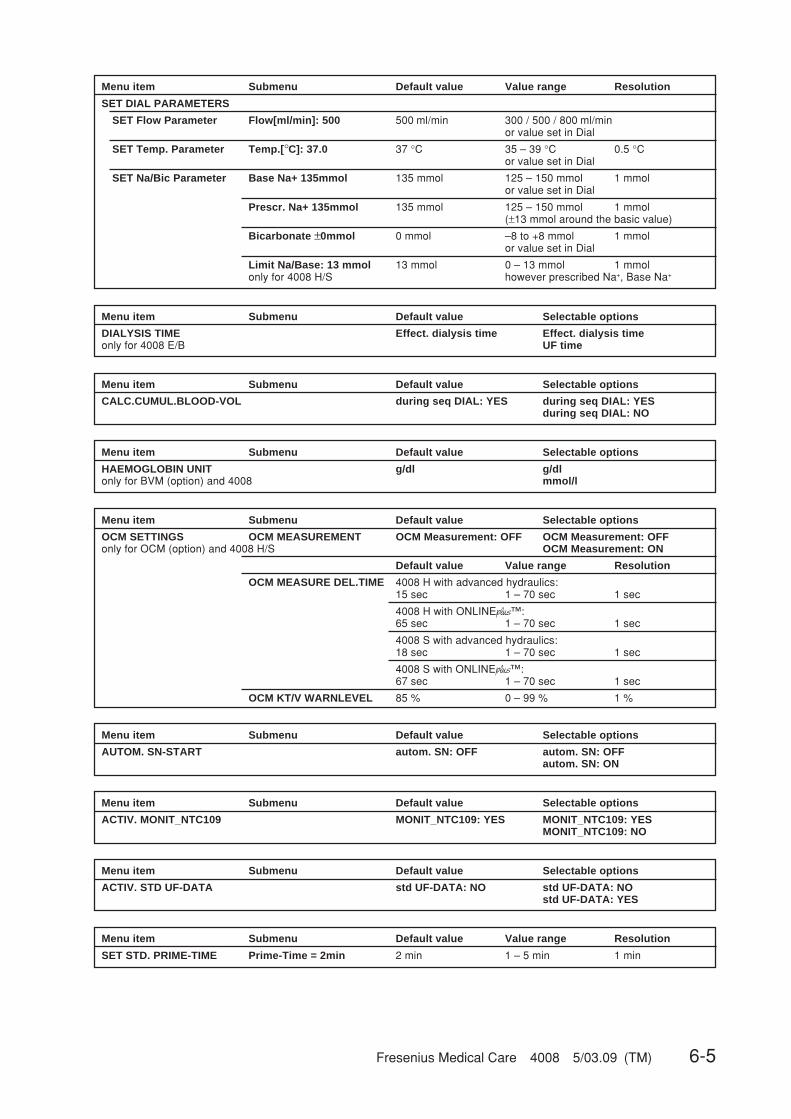
Fresenius Medical Care 4008 5/03.09 (TM) 6-5
Menu item Submenu Default value Selectable options
DIALYSIS TIME Effect. dialysis time Effect. dialysis timeonly for 4008 E/B UF time
Menu item Submenu Default value Selectable options
CALC.CUMUL.BLOOD-VOL during seq DIAL: YES during seq DIAL: YESduring seq DIAL: NO
Menu item Submenu Default value Selectable options
HAEMOGLOBIN UNIT g/dl g/dlonly for BVM (option) and 4008 mmol/l
Menu item Submenu Default value Selectable options
OCM SETTINGS OCM MEASUREMENT OCM Measurement: OFF OCM Measurement: OFFonly for OCM (option) and 4008 H/S OCM Measurement: ON
Default value Value range Resolution
OCM MEASURE DEL.TIME 4008 H with advanced hydraulics:15 sec 1 – 70 sec 1 sec
4008 H with ONLINEplus™:65 sec 1 – 70 sec 1 sec
4008 S with advanced hydraulics:18 sec 1 – 70 sec 1 sec
4008 S with ONLINEplus™:67 sec 1 – 70 sec 1 sec
OCM KT/V WARNLEVEL 85 % 0 – 99 % 1 %
Menu item Submenu Default value Selectable options
AUTOM. SN-START autom. SN: OFF autom. SN: OFFautom. SN: ON
Menu item Submenu Default value Selectable options
ACTIV. MONIT_NTC109 MONIT_NTC109: YES MONIT_NTC109: YESMONIT_NTC109: NO
Menu item Submenu Default value Selectable options
ACTIV. STD UF-DATA std UF-DATA: NO std UF-DATA: NOstd UF-DATA: YES
Menu item Submenu Default value Value range Resolution
SET STD. PRIME-TIME Prime-Time = 2min 2 min 1 – 5 min 1 min
Menu item Submenu Default value Value range Resolution
SET DIAL PARAMETERS
SET Flow Parameter Flow[ml/min]: 500 500 ml/min 300 / 500 / 800 ml/minor value set in Dial
SET Temp. Parameter Temp.[°C]: 37.0 37 °C 35 – 39 °C 0.5 °Cor value set in Dial
SET Na/Bic Parameter Base Na+ 135mmol 135 mmol 125 – 150 mmol 1 mmolor value set in Dial
Prescr. Na+ 135mmol 135 mmol 125 – 150 mmol 1 mmol(±13 mmol around the basic value)
Bicarbonate ±0mmol 0 mmol –8 to +8 mmol 1 mmolor value set in Dial
Limit Na/Base: 13 mmol 13 mmol 0 – 13 mmol 1 mmolonly for 4008 H/S however prescribed Na+, Base Na+

6-6 Fresenius Medical Care 4008 5/03.09 (TM)
Menu item Submenu Default value Selectable options
BPR/UFR-WARNING BPR/UFR-Warning: ON BPR/UFR-Warning: ONBPR/UFR-Warning: OFF
Menu item Submenu Default value Value range Resolution
SET RINSE-VOLUME RINSE-VOL: 1000 ml 1000 ml 0 – 5000 ml 100 ml
Menu item Submenu Default value Selectable options
T1-TEST AUTOSTART T1-T. Autostart: OFF T1-T. Autostart: OFFT1-T. Autostart: ON
Menu item Submenu Default value Value range Resolution
ONLINE plus SETTINGSonly for ONLINEplus™ (option)
ONLINE plus HD SET UF-Volume F/R 0 ml 0 – 1000 ml 100 ml
SET Rinsing Volume 1000 ml 0 – 5000 ml 100 ml
ONLINE plus HDF SET UF-Volume F/R 500 ml 0 – 1000 ml 100 ml
SET Rinsing Volume 1000 ml 0 – 5000 ml 100 ml
SET Substit.-Volume 12 l 0 – 210 l 1 l
ONLINE plus HF SET UF-Volume F/R 1000 ml 0 – 5000 ml 100 ml
SET Rinsing Volume 1000 ml 0 – 5000 ml 100 ml
SET Substit.-Volume 20 l 0 – 210 l 1 l
ONLINE plus MISC. SET Reinf.-Volume 240 ml 90 – 480 ml 30 ml
Menu item Submenu Default value Selectable options
SET CENTRAL-DELIVERY NO central-delivery NO central-deliverycentral Biccentral Acidcentral Acid + Biccentr acetate-supply
Menu item Adjustment
STORE DEFAULT VALUES Press OVERRIDEonly for 4008 E/BPress ALARMTONE MUTEonly for 4008 H/S
Menu item Submenu Default value Selectable options
AutoOFF after AutoON OFF OFFON
Menu item Submenu Default value Selectable options
SOUND I/O-SWITCH I/O-Warnsound: ON I/O-Warnsound: ONI/O-Warnsound: OFF
Menu item Submenu Default value Selectable options
SET KEY-CLICK key-click: ON key-click: ONonly for 4008 H/S key-click: OFF
Menu item Submenu Default value Selectable options
Init. CAMUS-baudrate 2400 baud 2400 baud9600 baud
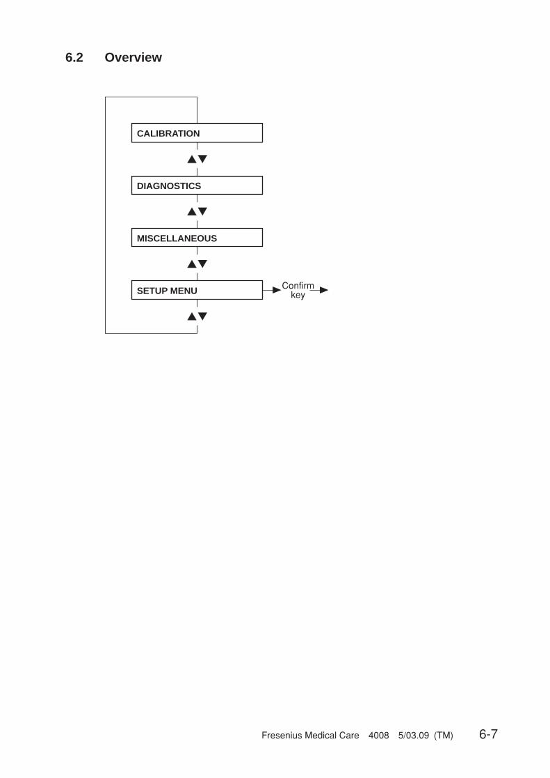
Fresenius Medical Care 4008 5/03.09 (TM) 6-7
6.2 Overview
▲▼
▲▼
▲▼
▲▼
CALIBRATION
Confirmkey
DIAGNOSTICS
MISCELLANEOUS
SETUP MENU

6-8 Fresenius Medical Care 4008 5/03.09 (TM)
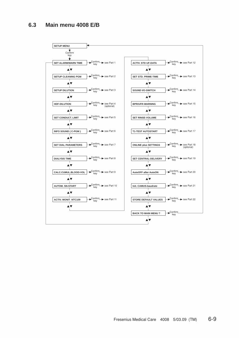
Fresenius Medical Care 4008 5/03.09 (TM) 6-9
6.3 Main menu 4008 E/B
▲▼
▲▼
▲▼
▲▼
▲▼
▲▼
▲▼
▲▼
▲▼
▲▼
▲▼
▲▼
▲▼
▲▼
▲▼
▲▼
▲▼
▲▼
▲▼
▲▼
▲▼
▲▼
▲▼
SETUP MENU
SET ALARM/WARN TIME Confirmkey see Part 1
SETUP CLEANING PGM Confirmkey see Part 2
INFO SOUND ( C-PGM )
Confirmkey see Part 3SETUP DILUTION
Confirmkey see Part 5SET CONDUCT. LIMIT
Confirmkey see Part 6
SET DIAL PARAMETERS Confirmkey see Part 7
DIALYSIS TIME Confirmkey see Part 8
AUTOM. SN-START Confirmkey
see Part 9
see Part 10
Confirmkey see Part 4
(optional)HDF-DILUTION
CALC.CUMUL.BLOOD-VOL Confirmkey
Confirmkey
see Part 11
Confirmkey
see Part 12
Confirmkey
see Part 13
see Part 15
see Part 16
see Part 14
see Part 17
see Part 18(optional)
see Part 19
see Part 20
Confirmkey
Confirmkey
Confirmkey
Confirmkey
Confirmkey
Confirmkey
Confirmkey
Confirmkey
ACTIV. MONIT_NTC109
ACTIV. STD UF-DATA
SET STD. PRIME-TIME
SOUND I/O-SWITCH
SET CENTRAL-DELIVERY
AutoOFF after AutoON
BACK TO MAIN MENU ?
BPR/UFR-WARNING
SET RINSE-VOLUME
T1-TEST AUTOSTART
ONLINE plus SETTINGS
Confirmkey
see Part 21ConfirmkeyInit. CAMUS-baudrate
see Part 22ConfirmkeySTORE DEFAULT VALUES
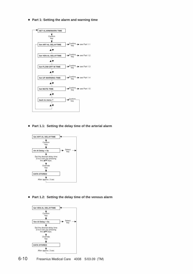
6-10 Fresenius Medical Care 4008 5/03.09 (TM)
● Part 1: Setting the alarm and warning time
▲▼
▲▼
▲▼
▲▼
▲▼
▲▼
SET ALARM/WARN TIME
Confirmkey
Set ART-AL DELAYTIME Confirmkey see Part 1.1
Set VEN-AL DELAYTIME Confirmkey see Part 1.2
Set FLOW-OFF W-TIME Confirmkey see Part 1.3
Set UF-WARNING-TIME Confirmkey see Part 1.4
Set MUTE-TIME Confirmkey see Part 1.5
back to menu ? Confirmkey
● Part 1.1: Setting the delay time of the arterial alarm
Set ART-AL DELAYTIME
Confirmkey
Art Al Delay = 5s
Overridekey
DATA STORED
After approx. 3 sec
Selectkey
Set the desired delay time (0 to 5 sec) by pressing
the ▲▼ keys.
● Part 1.2: Setting the delay time of the venous alarm
Set VEN-AL DELAYTIME
Confirmkey
Ven Al Delay = 5s
Overridekey
DATA STORED
After approx. 3 sec
Selectkey
Set the desired delay time (0 to 5 sec) by pressing
the ▲▼ keys.

Fresenius Medical Care 4008 5/03.09 (TM) 6-11
● Part 1.3: Setting the flow-off warning time
Set FLOW-OFF W-TIME
Confirmkey
Flow-Off-T = 30min
Overridekey
DATA STORED
After approx. 3 sec
Selectkey
Set the desired warning time (30, 45, 60 min) by pressing
the ▲▼ keys.
● Part 1.4: Setting the UF warning time
Set UF-WARNING-TIME
Confirmkey
UF-Warn-Time = 10min
Overridekey
DATA STORED
After approx. 3 sec
Selectkey
Set the desired warning time (10, 30 min) by pressing
the ▲▼ keys.
● Part 1.5: Setting the mute time
Set MUTE-TIME
Confirmkey
MUTE-Time = 1min
Overridekey
DATA STORED
After approx. 3 sec
Selectkey
Set the desired time (1, 2 min) by pressing
the ▲▼ keys.
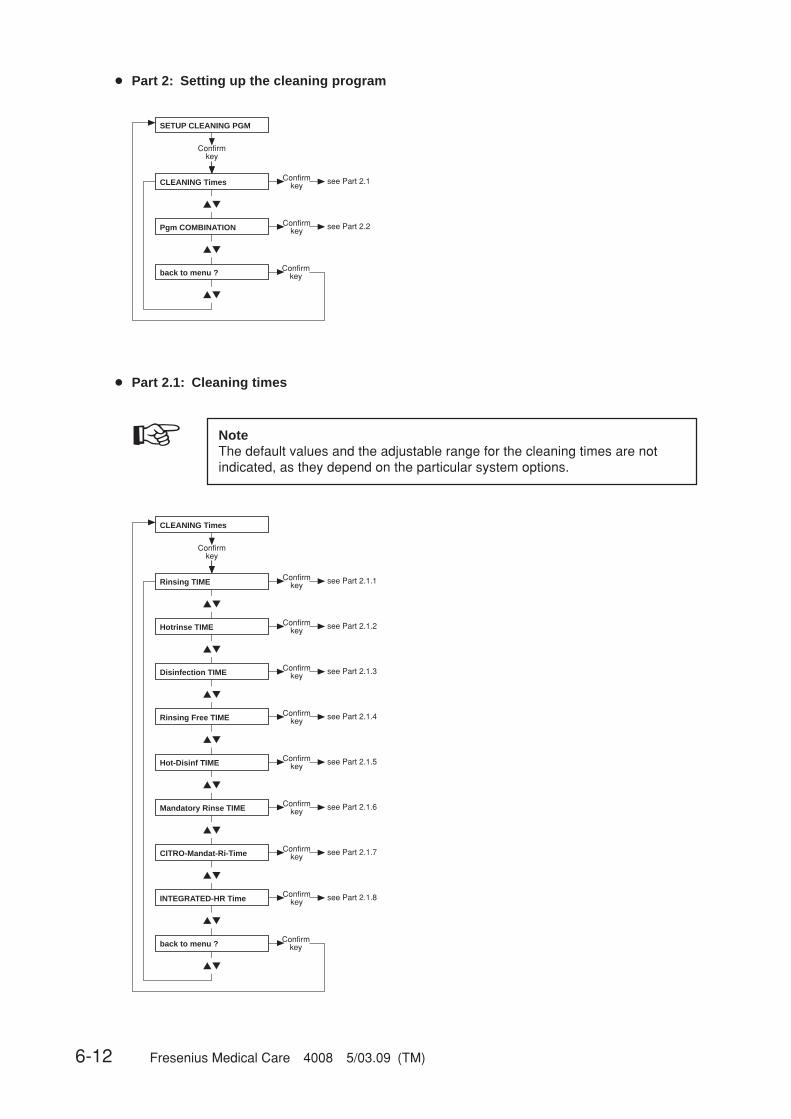
6-12 Fresenius Medical Care 4008 5/03.09 (TM)
● Part 2: Setting up the cleaning program
▲▼
▲▼
▲▼
SETUP CLEANING PGM
Confirmkey
CLEANING Times Confirmkey see Part 2.1
Pgm COMBINATION Confirmkey see Part 2.2
back to menu ? Confirmkey
● Part 2.1: Cleaning times
☞ NoteThe default values and the adjustable range for the cleaning times are notindicated, as they depend on the particular system options.
▲▼
▲▼
▲▼
▲▼
▲▼
▲▼
▲▼
▲▼
▲▼
CLEANING Times
Confirmkey
Rinsing TIME Confirmkey see Part 2.1.1
Hotrinse TIME Confirmkey see Part 2.1.2
Disinfection TIME Confirmkey see Part 2.1.3
Rinsing Free TIME Confirmkey see Part 2.1.4
Hot-Disinf TIME Confirmkey see Part 2.1.5
back to menu ? Confirmkey
Mandatory Rinse TIME Confirmkey see Part 2.1.6
CITRO-Mandat-Ri-Time Confirmkey see Part 2.1.7
INTEGRATED-HR Time Confirmkey see Part 2.1.8

Fresenius Medical Care 4008 5/03.09 (TM) 6-13
● Part 2.1.1: Rinsing time
Rinsing TIME
Confirmkey
Rinsing Time = xxmin
Overridekey
DATA STORED
After approx. 3 sec
Selectkey
Set the desired timeby pressing the ▲▼ keys.
● Part 2.1.2: Hot rinsing time
Hotrinse TIME
Confirmkey
H-Rinse Time = xxmin
Overridekey
DATA STORED
After approx. 3 sec
Selectkey
Set the desired time by pressing the ▲▼ keys.
● Part 2.1.3: Disinfection time
Disinfection TIME
Confirmkey
Disinf. Time = xxmin
Overridekey
DATA STORED
After approx. 3 sec
Selectkey
Set the desired time by pressing the ▲▼ keys.
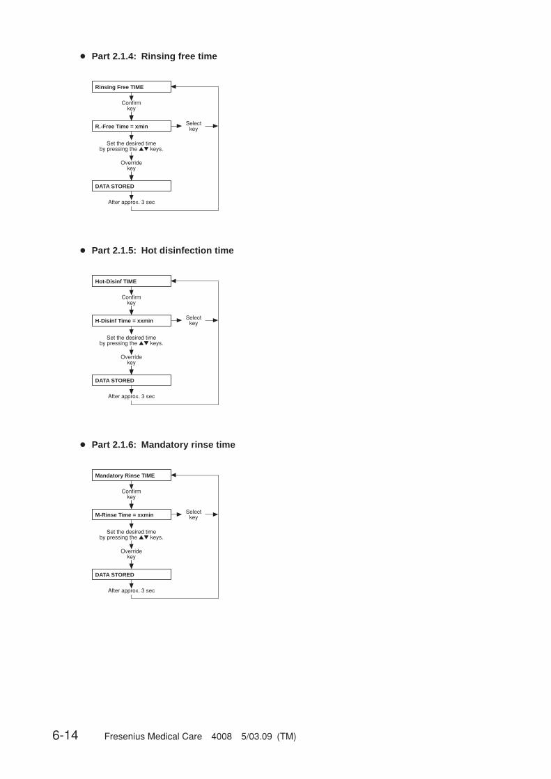
6-14 Fresenius Medical Care 4008 5/03.09 (TM)
● Part 2.1.4: Rinsing free time
Rinsing Free TIME
Confirmkey
R.-Free Time = xmin
Overridekey
DATA STORED
After approx. 3 sec
Selectkey
Set the desired time by pressing the ▲▼ keys.
● Part 2.1.5: Hot disinfection time
Hot-Disinf TIME
Confirmkey
H-Disinf Time = xxmin
Overridekey
DATA STORED
After approx. 3 sec
Selectkey
Set the desired time by pressing the ▲▼ keys.
● Part 2.1.6: Mandatory rinse time
Mandatory Rinse TIME
Confirmkey
M-Rinse Time = xxmin
Overridekey
DATA STORED
After approx. 3 sec
Selectkey
Set the desired time by pressing the ▲▼ keys.

Fresenius Medical Care 4008 5/03.09 (TM) 6-15
● Part 2.1.7: Citro mandatory rinse time
CITRO Mandat-Ri-Time
Confirmkey
CITRO-MRTime = xxmin
Overridekey
DATA STORED
After approx. 3 sec
Selectkey
Set the desired time by pressing the ▲▼ keys.
● Part 2.1.8: Integrated hot rinse time
INTEGRATED-HR Time
Confirmkey
INT. HR-Time = xxmin
Overridekey
DATA STORED
After approx. 3 sec
Selectkey
Set the desired time by pressing the ▲▼ keys.
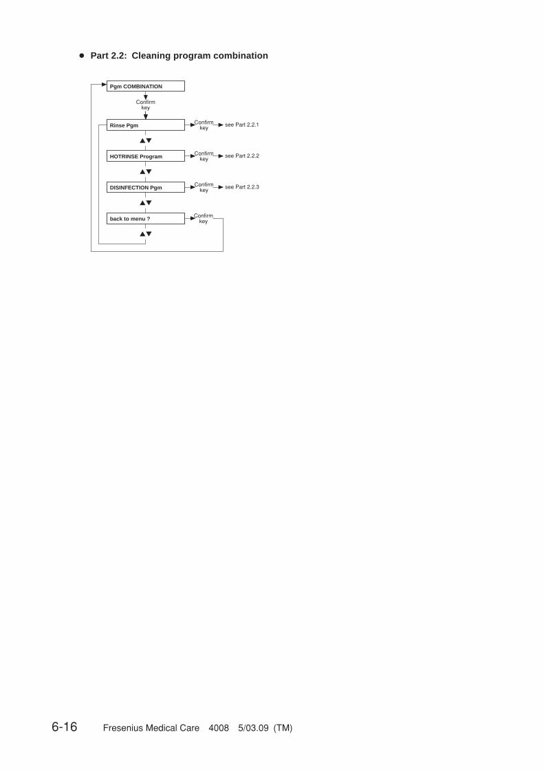
6-16 Fresenius Medical Care 4008 5/03.09 (TM)
● Part 2.2: Cleaning program combination
▲▼
▲▼
▲▼
▲▼
Pgm COMBINATION
Confirmkey
Rinse Pgm Confirmkey see Part 2.2.1
HOTRINSE Program Confirmkey see Part 2.2.2
DISINFECTION Pgm Confirmkey see Part 2.2.3
back to menu ? Confirmkey
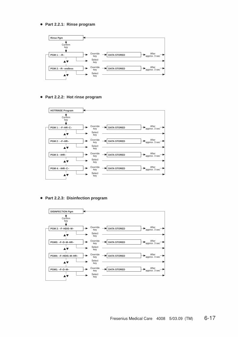
Fresenius Medical Care 4008 5/03.09 (TM) 6-17
● Part 2.2.1: Rinse program
▲▼
▲▼
Rinse Pgm
Confirmkey
PGM 1 : –R– Overridekey
PGM 2: –R– endless
DATA STORED
Selectkey
Overridekey DATA STORED
Selectkey
Afterapprox. 3 sec
Afterapprox. 3 sec
● Part 2.2.2: Hot rinse program
▲▼
▲▼
▲▼
▲▼
HOTRINSE Program
Confirmkey
PGM 1 : –F–HR–C– Overridekey
PGM 3: –IHR–
DATA STORED
Selectkey
Overridekey DATA STORED
Selectkey
Afterapprox. 3 sec
Afterapprox. 3 sec
PGM 2 : –F–HR– Overridekey DATA STORED
Selectkey
Afterapprox. 3 sec
PGM 4: –IHR–C– Overridekey DATA STORED
Selectkey
Afterapprox. 3 sec
● Part 2.2.3: Disinfection program
▲▼
▲▼
▲▼
▲▼
DISINFECTION Pgm
Confirmkey
PGM 2: –F–HDIS–M– Overridekey
PGM1: –F–D–M–
DATA STORED
Selectkey
Overridekey DATA STORED
Selectkey
PGM3: –F–D–M–HR–
Overridekey DATA STORED
Selectkey
PGM4: –F–HDIS–M–HR–
Overridekey DATA STORED
Selectkey
Afterapprox. 3 sec
Afterapprox. 3 sec
Afterapprox. 3 sec
Afterapprox. 3 sec
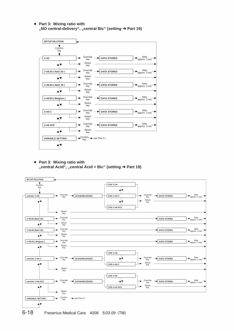
6-18 Fresenius Medical Care 4008 5/03.09 (TM)
▲▼
▲▼
▲▼
▲▼
▲▼
▲▼
▲▼
SETUP DILUTION
Confirmkey
Overridekey DATA STORED
Selectkey
Overridekey DATA STORED
Selectkey
Overridekey DATA STORED
Selectkey
Overridekey DATA STORED
Selectkey
Afterapprox. 3 sec
Afterapprox. 3 sec
Afterapprox. 3 sec
Afterapprox. 3 sec
Overridekey DATA STORED
Selectkey
Afterapprox. 3 sec
DATA STORED Afterapprox. 3 sec
Overridekey
Selectkey
1+34
1+35.83 ( NaCl 20 )
1+35.83 ( NaCl 26 )
1+35.83 ( Belgium )
1+44 C
1+44 ACF
VARIABLE SETTING Confirmkey see Part 3.1
● Part 3: Mixing ratio with„NO central-delivery“, „central Bic“ (setting ➜ Part 19)
▲▼
▲▼
▲▼
▲▼
▲▼
▲▼
▲▼ ▲▼
▲▼
▲▼
▲▼
SETUP DILUTION
Confirmkey
canister 1+34
1+35.83 (NaCl 20)
1+35.83 (NaCl 26)
1+35.83 ( Belgium )
canister 1+44 C
canister 1+44 ACF
VARIABLE SETTING
Overridekey
Selectkey
Overridekey
Selectkey
Overridekey
Selectkey
Overridekey
Selectkey
Overridekey
Selectkey
Overridekey
Selectkey
Confirmkey see Part 3.1
Afterapprox. 3 sec
Afterapprox. 3 sec
Afterapprox. 3 sec
Afterapprox. 3 sec
Afterapprox. 3 sec
Afterapprox. 3 sec
DATA STORED
DATA STORED
DATA STORED
DATA STORED
DATA STORED
DATA STORED
ACKNOWLEDGED
CDS 1+34
CDS 1+44 C
CDS 1+44 ACF
Overridekey
Selectkey
CDS 1+34
CDS 1+44 ACF
Overridekey
Selectkey
ACKNOWLEDGED
CDS 1+34
CDS 1+44 C
Overridekey
Selectkey
ACKNOWLEDGED
● Part 3: Mixing ratio with„central Acid“, „central Acid + Bic“ (setting ➜ Part 19)
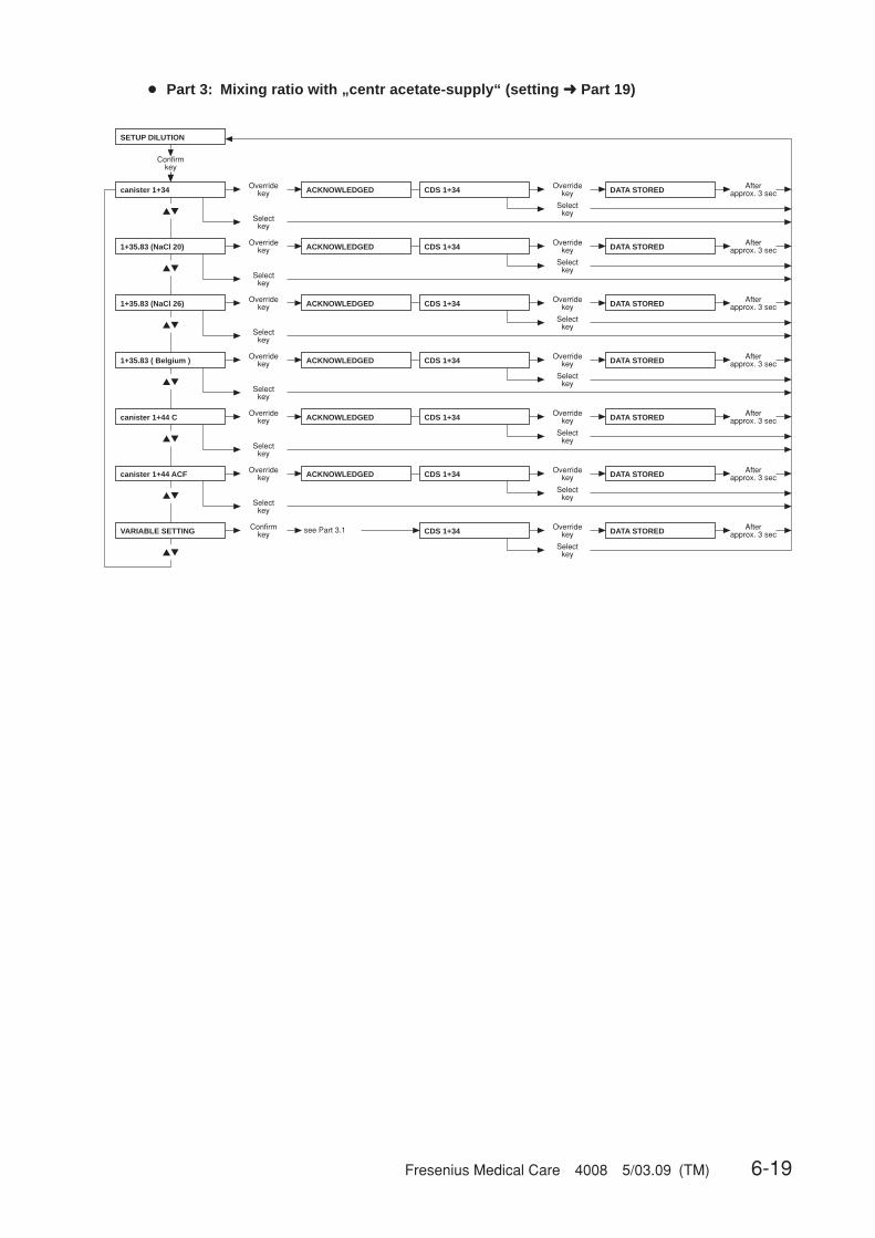
Fresenius Medical Care 4008 5/03.09 (TM) 6-19
▲▼
▲▼
▲▼
▲▼
▲▼
▲▼
▲▼
SETUP DILUTION
Confirmkey
canister 1+34
1+35.83 (NaCl 20)
1+35.83 (NaCl 26)
1+35.83 ( Belgium )
canister 1+44 C
canister 1+44 ACF
VARIABLE SETTING
Overridekey
Selectkey
Afterapprox. 3 secDATA STOREDACKNOWLEDGED CDS 1+34 Override
key
Selectkey
Overridekey
Selectkey
Afterapprox. 3 secDATA STOREDOverride
key
Selectkey
Overridekey
Selectkey
Afterapprox. 3 secDATA STOREDOverride
key
Selectkey
Overridekey
Selectkey
Afterapprox. 3 secDATA STOREDOverride
key
Selectkey
Overridekey
Afterapprox. 3 secDATA STOREDOverride
key
Selectkey
Afterapprox. 3 secDATA STOREDOverride
key
Selectkey
CDS 1+34
CDS 1+34
CDS 1+34
CDS 1+34
CDS 1+34
Selectkey
Confirmkey see Part 3.1
Overridekey
Afterapprox. 3 secDATA STOREDOverride
key
Selectkey
CDS 1+34
Selectkey
ACKNOWLEDGED
ACKNOWLEDGED
ACKNOWLEDGED
ACKNOWLEDGED
ACKNOWLEDGED
● Part 3: Mixing ratio with „centr acetate-supply“ (setting ➜ Part 19)

6-20 Fresenius Medical Care 4008 5/03.09 (TM)
CautionThe operator or technician is informed about his duty of care to enter the com-ponent parameters and settings correctly or to check them and to set the CDalarm window to the expected conductivity value.When using the programmable mixing ratio (dilution), make sure to use theright concentrate.Using a bibag® in combination with the programmable mixing ratio (dilution) isnot allowed.Only enter authorized, programmable mixing ratios (dilutions).
● Part 3.1: Programmable mixing ratio (dilution)
▲▼
SETUP DILUTION
Confirmkey
VARIABLE SETTING Confirmkey B-Comp[part] : 0.800
Overridekey
ACKNOWLEDGED
After approx. 3 sec
Set the desired value (0.800 – 2.500)
by pressing the ▲▼ keys.
Selectkey
RO[part] : 30.000
Overridekey
ACKNOWLEDGED
After approx. 3 sec
Selectkey
HCO3–[mmol]: 25
Overridekey
ACKNOWLEDGED
After approx. 3 sec
Selectkey
Na(B)[mmol]: 25
Overridekey
DATA STORED
After approx. 3 sec
Selectkey
Set the desired value (30.000 – 45.000)
by pressing the ▲▼ keys.
Set the desired value (25 – 45)
by pressing the ▲▼ keys.
Set the desired value (25 – 80)
by pressing the ▲▼ keys.
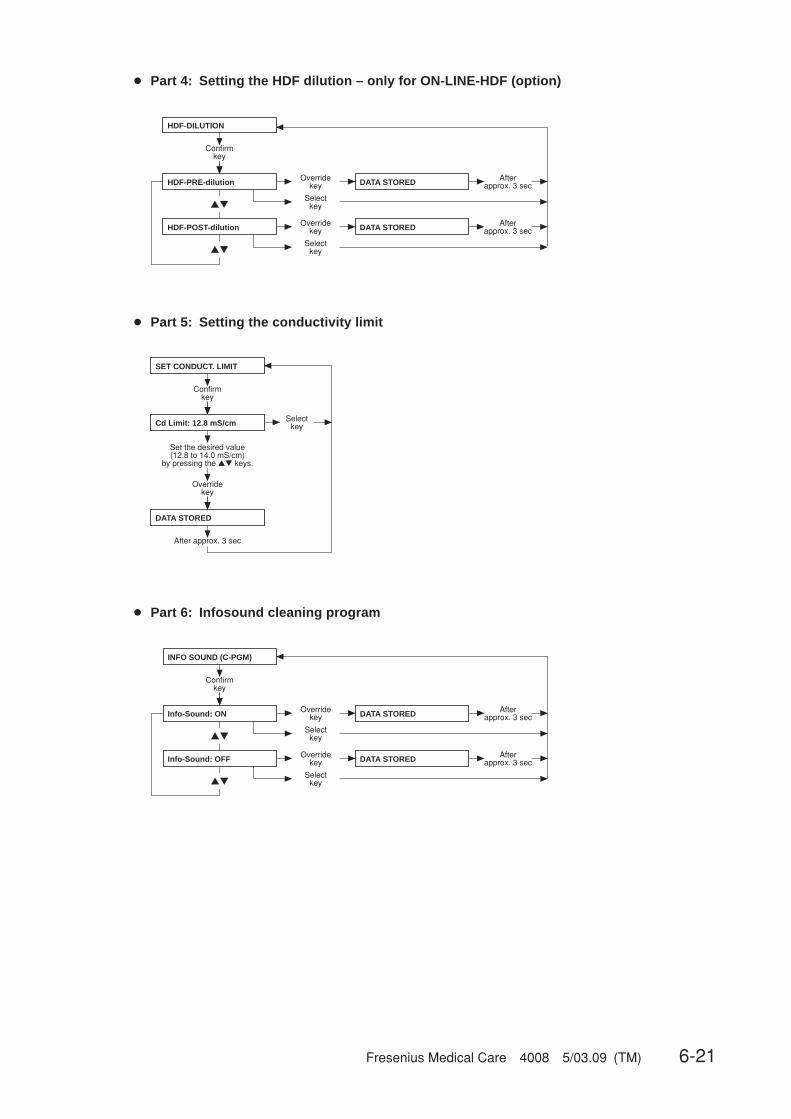
Fresenius Medical Care 4008 5/03.09 (TM) 6-21
● Part 4: Setting the HDF dilution – only for ON-LINE-HDF (option)
▲▼
▲▼
HDF-DILUTION
Confirmkey
HDF-PRE-dilution Overridekey
HDF-POST-dilution
DATA STORED
Selectkey
Overridekey DATA STORED
Selectkey
Afterapprox. 3 sec
Afterapprox. 3 sec
● Part 5: Setting the conductivity limit
SET CONDUCT. LIMIT
Confirmkey
Cd Limit: 12.8 mS/cm
Overridekey
DATA STORED
After approx. 3 sec
Selectkey
Set the desired value (12.8 to 14.0 mS/cm)
by pressing the ▲▼ keys.
● Part 6: Infosound cleaning program
▲▼
▲▼
INFO SOUND (C-PGM)
Confirmkey
Info-Sound: ON Overridekey
Info-Sound: OFF
DATA STORED
Selectkey
Overridekey DATA STORED
Selectkey
Afterapprox. 3 sec
Afterapprox. 3 sec
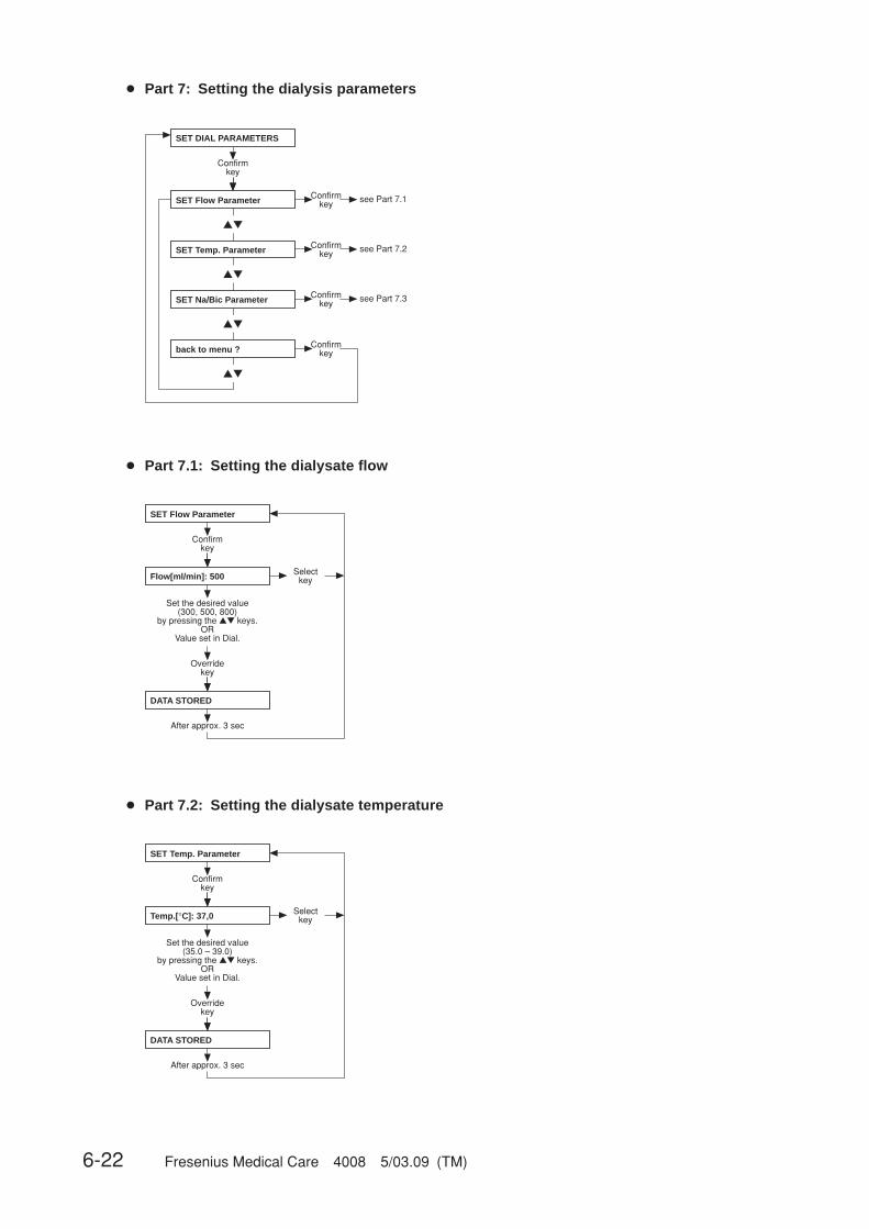
6-22 Fresenius Medical Care 4008 5/03.09 (TM)
● Part 7: Setting the dialysis parameters
▲▼
▲▼
▲▼
▲▼
SET Flow Parameter see Part 7.1
SET Temp. Parameter see Part 7.2
SET Na/Bic Parameter see Part 7.3
Confirmkey
Confirmkey
back to menu ?
SET DIAL PARAMETERS
Confirmkey
Confirmkey
Confirmkey
● Part 7.1: Setting the dialysate flow
Flow[ml/min]: 500
Confirmkey
Overridekey
DATA STORED
After approx. 3 sec
Selectkey
Set the desired value (300, 500, 800)
by pressing the ▲▼ keys.OR
Value set in Dial.
SET Flow Parameter
● Part 7.2: Setting the dialysate temperature
Confirmkey
Temp.[°C]: 37,0
Overridekey
DATA STORED
After approx. 3 sec
Selectkey
Set the desired value (35.0 – 39.0)
by pressing the ▲▼ keys.OR
Value set in Dial.
SET Temp. Parameter
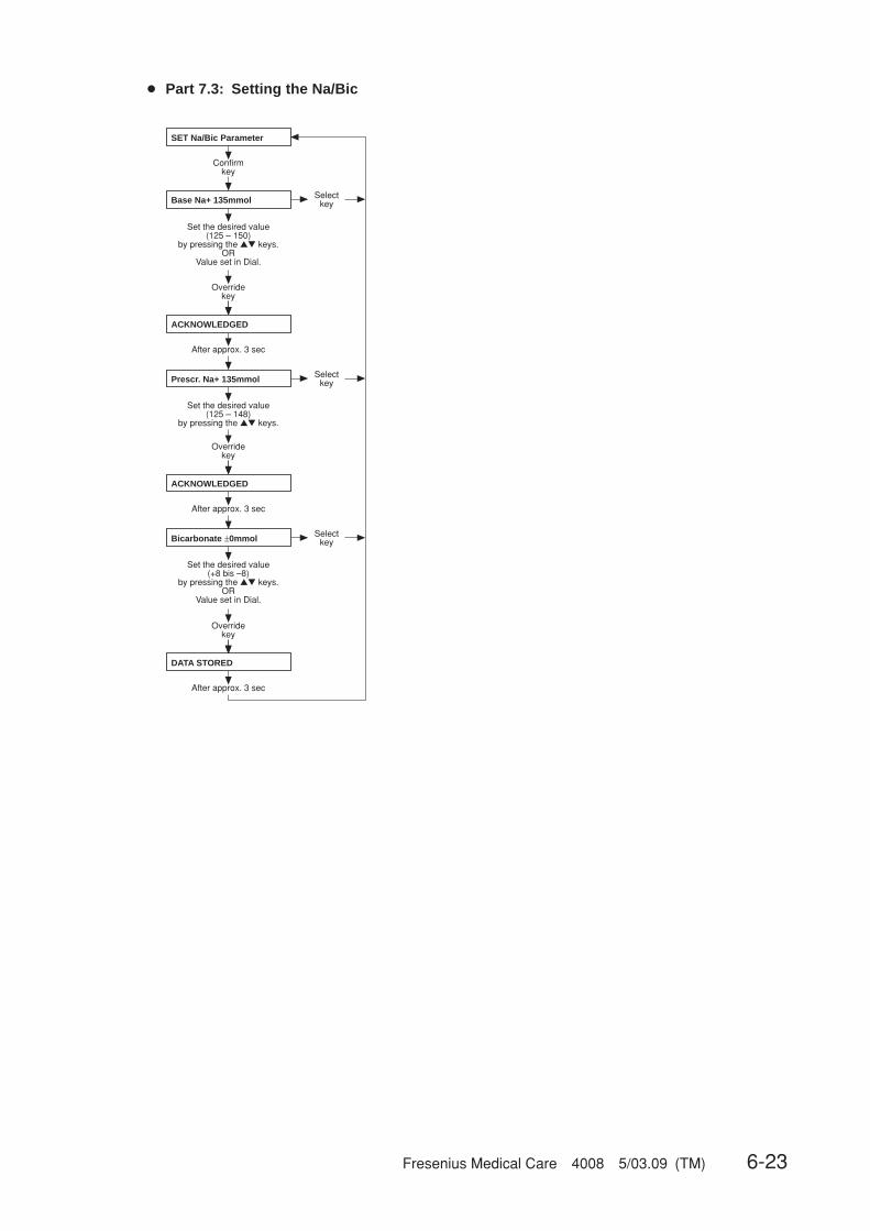
Fresenius Medical Care 4008 5/03.09 (TM) 6-23
● Part 7.3: Setting the Na/Bic
SET Na/Bic Parameter
Confirmkey
Base Na+ 135mmol
Overridekey
ACKNOWLEDGED
After approx. 3 sec
Selectkey
Set the desired value (125 – 150)
by pressing the ▲▼ keys.OR
Value set in Dial.
Prescr. Na+ 135mmol
Overridekey
ACKNOWLEDGED
After approx. 3 sec
Selectkey
Bicarbonate ±0mmol
Overridekey
DATA STORED
After approx. 3 sec
Selectkey
Set the desired value (125 – 148)
by pressing the ▲▼ keys.
Set the desired value (+8 bis –8)
by pressing the ▲▼ keys.OR
Value set in Dial.

6-24 Fresenius Medical Care 4008 5/03.09 (TM)
● Part 8: Dialysis time
▲▼
▲▼
DIALYSIS TIME
Confirmkey
Effect Dialysis Time Overridekey
UF-Time
DATA STORED
Selectkey
Overridekey DATA STORED
Selectkey
Afterapprox. 3 sec
Afterapprox. 3 sec
● Part 9: Cumulated blood volume
▲▼
▲▼
CALC.CUMUL.BLOOD-VOL
during seq DIAL: YES
during seq DIAL: NO
Confirmkey
Overridekey DATA STORED
Selectkey
Overridekey DATA STORED
Selectkey
Afterapprox. 3 sec
Afterapprox. 3 sec
● Part 10: Automatic Single-Needle start
▲▼
▲▼
Confirmkey
Overridekey DATA STORED
Selectkey
Overridekey DATA STORED
Selectkey
Afterapprox. 3 sec
Afterapprox. 3 sec
AUTOM. SN-START
autom. SN: OFF
autom. SN: ON
● Part 11: Activation of Monit_NTC 109
▲▼
▲▼
Confirmkey
Overridekey DATA STORED
Selectkey
Overridekey DATA STORED
Selectkey
Afterapprox. 3 sec
Afterapprox. 3 sec
ACTIV. MONIT_NTC109
MONIT_NTC109: YES
MONIT_NTC109: NO
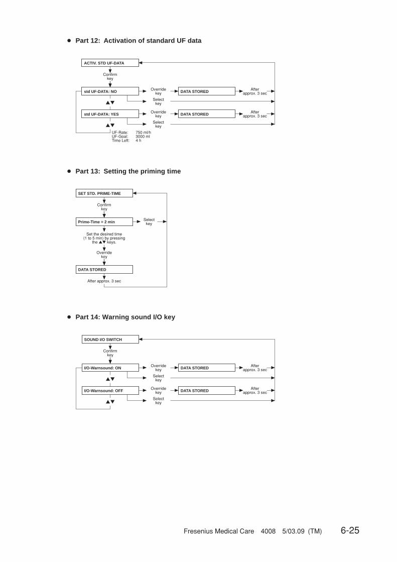
Fresenius Medical Care 4008 5/03.09 (TM) 6-25
● Part 12: Activation of standard UF data
▲▼
▲▼
ACTIV. STD UF-DATA
Confirmkey
std UF-DATA: NO Overridekey
std UF-DATA: YES
DATA STORED
Selectkey
Overridekey DATA STORED
Selectkey
Afterapprox. 3 sec
Afterapprox. 3 sec
UF-Rate:UF-Goal:Time Left:
750 ml/h3000 ml4 h
● Part 13: Setting the priming time
SET STD. PRIME-TIME
Confirmkey
Prime-Time = 2 min
Overridekey
DATA STORED
After approx. 3 sec
Selectkey
Set the desired time (1 to 5 min) by pressing
the ▲▼ keys.
● Part 14: Warning sound I/O key
▲▼
▲▼
SOUND I/O SWITCH
Confirmkey
I/O-Warnsound: ON Overridekey
I/O-Warnsound: OFF
DATA STORED
Selectkey
Overridekey DATA STORED
Selectkey
Afterapprox. 3 sec
Afterapprox. 3 sec
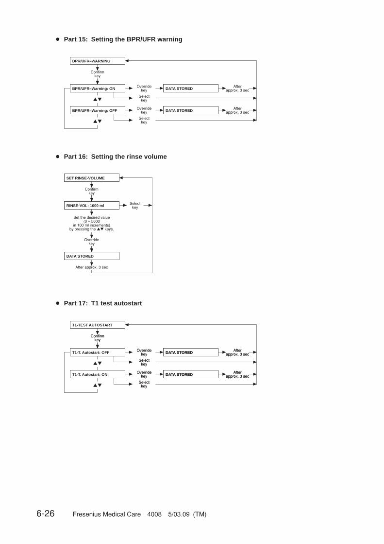
6-26 Fresenius Medical Care 4008 5/03.09 (TM)
● Part 15: Setting the BPR/UFR warning
▲▼
▲▼
BPR/UFR–WARNING
Confirmkey
BPR/UFR–Warning: ON Overridekey
BPR/UFR–Warning: OFF
DATA STORED
Selectkey
Overridekey DATA STORED
Selectkey
Afterapprox. 3 sec
Afterapprox. 3 sec
● Part 16: Setting the rinse volume
Confirmkey
Overridekey
DATA STORED
After approx. 3 sec
Selectkey
Set the desired value (0 – 5000
in 100 ml increments)by pressing the ▲▼ keys.
SET RINSE-VOLUME
RINSE-VOL: 1000 ml
● Part 17: T1 test autostart
▲▼
▲▼
Confirmkey
Overridekey DATA STORED
Selectkey
Overridekey DATA STORED
Selectkey
Afterapprox. 3 sec
Afterapprox. 3 sec
Confirmkey
Overridekey DATA STORED
Selectkey
Overridekey DATA STORED
Selectkey
Afterapprox. 3 sec
Afterapprox. 3 sec
T1-TEST AUTOSTART
T1-T. Autostart: OFF
T1-T. Autostart: ON

Fresenius Medical Care 4008 5/03.09 (TM) 6-27
● Part 18: ONLINEplusplusplusplusplus™ settings – only for ONLINEplusplusplusplusplus™ (option)
▲▼
▲▼
▲▼
▲▼
▲▼
Confirmkey
Confirmkey
back to menu ?
see Part 18.1
see Part 18.2
see Part 18.3
see Part 18.4
Confirmkey
Confirmkey
Confirmkey
Confirmkey
ONLINE plus SETTINGS
ONLINE plus HD
ONLINE plus HDF
ONLINE plus HF
ONLINE plus MISC.
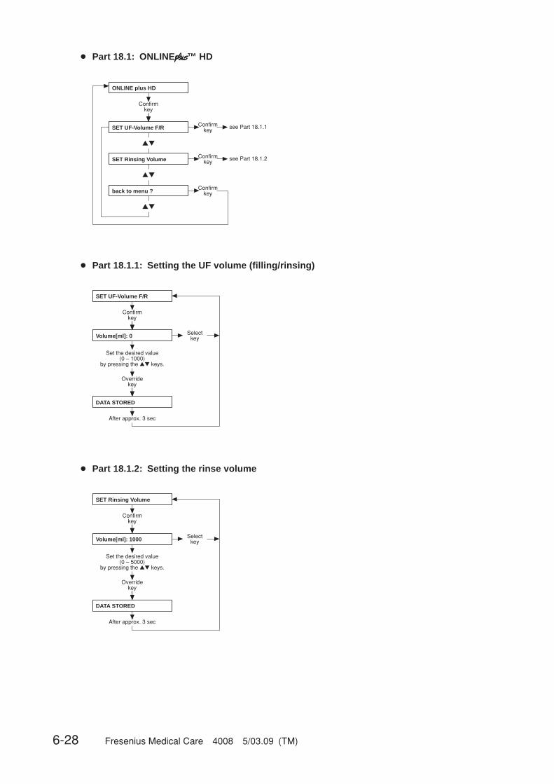
6-28 Fresenius Medical Care 4008 5/03.09 (TM)
● Part 18.1: ONLINEplusplusplusplusplus™ HD
▲▼
▲▼
▲▼
Confirmkey
Confirmkey
back to menu ?
see Part 18.1.1
see Part 18.1.2Confirmkey
Confirmkey
ONLINE plus HD
SET UF-Volume F/R
SET Rinsing Volume
● Part 18.1.1: Setting the UF volume (filling/rinsing)
SET UF-Volume F/R
Confirmkey
Overridekey
DATA STORED
After approx. 3 sec
Selectkey
Set the desired value (0 – 1000)
by pressing the ▲▼ keys.
Volume[ml]: 0
● Part 18.1.2: Setting the rinse volume
Confirmkey
Overridekey
DATA STORED
After approx. 3 sec
Selectkey
Set the desired value (0 – 5000)
by pressing the ▲▼ keys.
Volume[ml]: 1000
SET Rinsing Volume
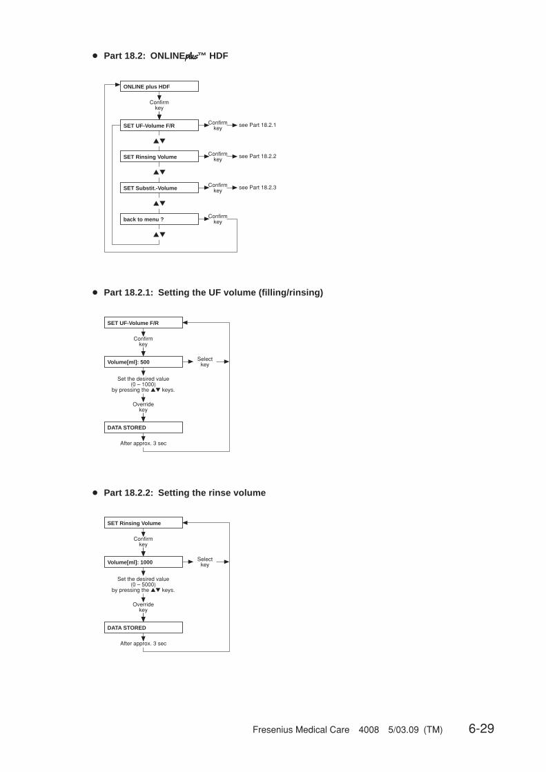
Fresenius Medical Care 4008 5/03.09 (TM) 6-29
● Part 18.2: ONLINEplusplusplusplusplus™ HDF
▲▼
▲▼
▲▼
▲▼
Confirmkey
Confirmkey
back to menu ?
see Part 18.2.1SET UF-Volume F/R
SET Rinsing Volume
ONLINE plus HDF
SET Substit.-Volume
Confirmkey see Part 18.2.2
Confirmkey see Part 18.2.3
Confirmkey
● Part 18.2.1: Setting the UF volume (filling/rinsing)
SET UF-Volume F/R
Confirmkey
Overridekey
DATA STORED
After approx. 3 sec
Selectkey
Set the desired value (0 – 1000)
by pressing the ▲▼ keys.
Volume[ml]: 500
● Part 18.2.2: Setting the rinse volume
Confirmkey
Overridekey
DATA STORED
After approx. 3 sec
Selectkey
Set the desired value (0 – 5000)
by pressing the ▲▼ keys.
Volume[ml]: 1000
SET Rinsing Volume

6-30 Fresenius Medical Care 4008 5/03.09 (TM)
● Part 18.2.3: Setting the substituate volume
Confirmkey
Overridekey
DATA STORED
After approx. 3 sec
Selectkey
Set the desired value (0 – 210)
by pressing the ▲▼ keys.
SET Substit.-Volume
Volume[l]: 12

Fresenius Medical Care 4008 5/03.09 (TM) 6-31
● Part 18.3: ONLINEplusplusplusplusplus™ HF
▲▼
▲▼
▲▼
▲▼
Confirmkey
Confirmkey
back to menu ?
see Part 18.3.1SET UF-Volume F/R
SET Rinsing Volume
ONLINE plus HF
SET Substit.-Volume
Confirmkey see Part 18.3.2
Confirmkey see Part 18.3.3
Confirmkey
● Part 18.3.1: Setting the UF volume (filling/rinsing)
SET UF-Volume F/R
Confirmkey
Overridekey
DATA STORED
After approx. 3 sec
Selectkey
Set the desired value (0 – 5000)
by pressing the ▲▼ keys.
Volume[ml]: 1000
● Part 18.3.2: Setting the rinse volume
Confirmkey
Overridekey
DATA STORED
After approx. 3 sec
Selectkey
Set the desired value (0 – 5000)
by pressing the ▲▼ keys.
Volume[ml]: 1000
SET Rinsing Volume
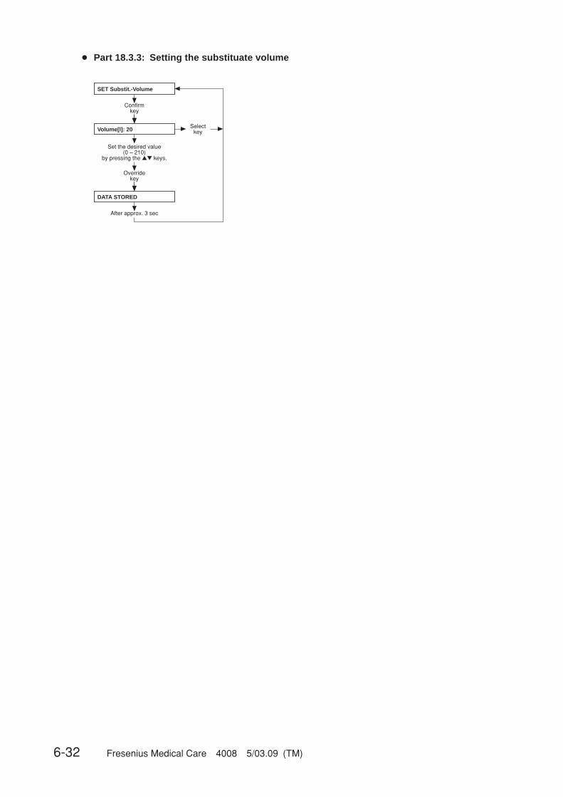
6-32 Fresenius Medical Care 4008 5/03.09 (TM)
● Part 18.3.3: Setting the substituate volume
Confirmkey
Overridekey
DATA STORED
After approx. 3 sec
Selectkey
Set the desired value (0 – 210)
by pressing the ▲▼ keys.
SET Substit.-Volume
Volume[l]: 20
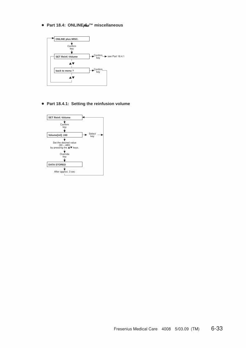
Fresenius Medical Care 4008 5/03.09 (TM) 6-33
● Part 18.4: ONLINEplusplusplusplusplus™ miscellaneous
▲▼
▲▼
Confirmkey
Confirmkey
back to menu ?
see Part 18.4.1
ONLINE plus MISC.
Confirmkey
SET Reinf.-Volume
● Part 18.4.1: Setting the reinfusion volume
Confirmkey
Overridekey
DATA STORED
After approx. 3 sec
Selectkey
Set the desired value (90 – 480)
by pressing the ▲▼ keys.
SET Reinf.-Volume
Volume[ml]: 240

6-34 Fresenius Medical Care 4008 5/03.09 (TM)
● Part 19: Setting the parameters for central delivery system
▲▼
▲▼
▲▼
▲▼
▲▼
SET CENTRAL-DELIVERY
Confirmkey
NO central-delivery
central Bic
DATA STORED
DATA STORED
central Acid DATA STORED
central Acid + Bic DATA STORED
Afterapprox. 3 sec
Afterapprox. 3 sec
Afterapprox. 3 sec
Afterapprox. 3 sec
centr acetate-supply DATA STORED Afterapprox. 3 sec
Overridekey
Selectkey
Overridekey
Selectkey
Overridekey
Selectkey
Overridekey
Selectkey
Overridekey
Selectkey
SETUP DILUTION
SETUP DILUTION
SETUP DILUTION
SETUP DILUTION
Afterapprox. 3 sec
Afterapprox. 3 sec
Afterapprox. 3 sec
Afterapprox. 3 sec
SETUP DILUTION Afterapprox. 3 sec
● Part 20: AutoOFF after AutoON
AutoOFF after AutoON
Confirmkey
Auto OFF: OFF DATA STORED Afterapprox. 3 sec
Auto OFF: ON DATA STORED
▲▼
Overridekey
Selectkey
▲▼
Overridekey
Selectkey
Afterapprox. 3 sec
● Part 21: CAMUS-baudrate
Init. CAMUS-baudrate
baudrate: 2400 baud
baudrate: 9600 baud
▲▼
▲▼
Confirmkey
DATA STORED Afterapprox. 3 sec
DATA STORED
Overridekey
Selectkey
Overridekey
Selectkey
Afterapprox. 3 sec
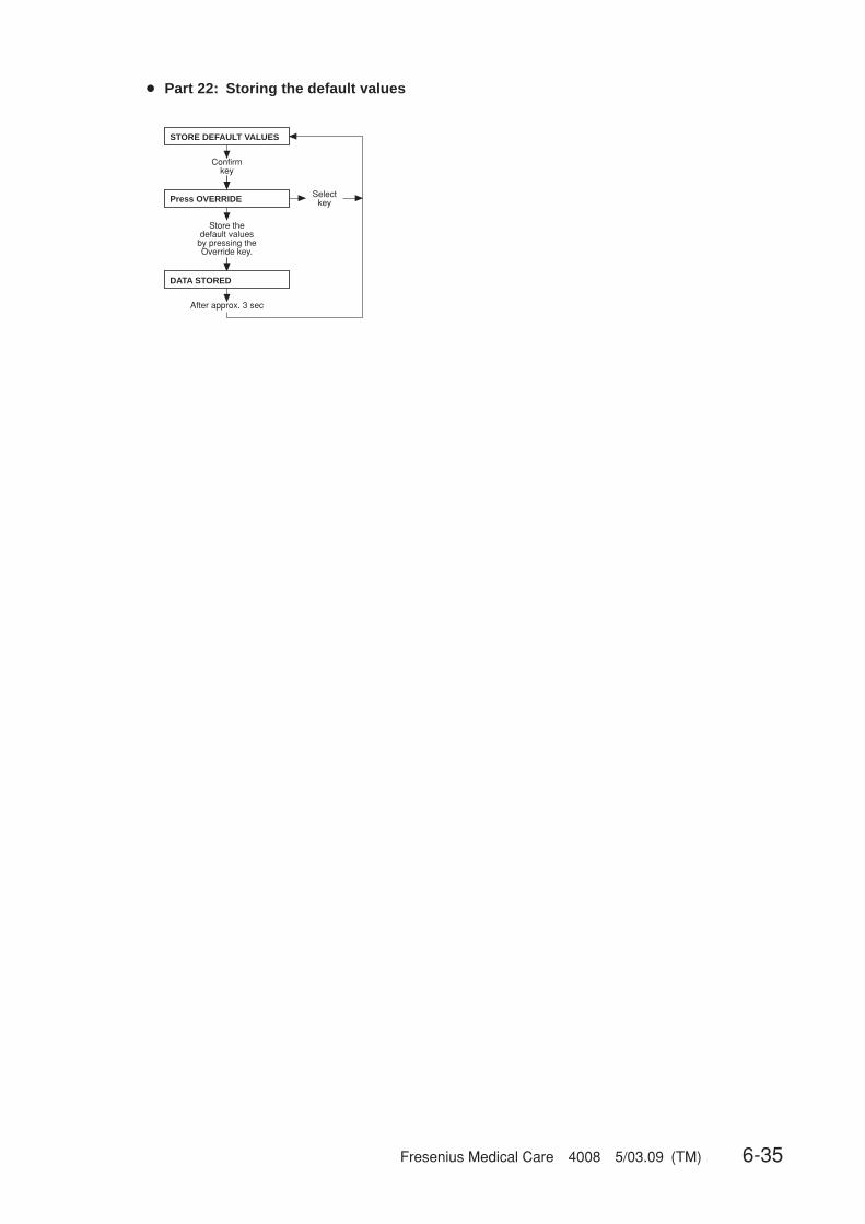
Fresenius Medical Care 4008 5/03.09 (TM) 6-35
● Part 22: Storing the default values
STORE DEFAULT VALUES
Confirmkey
Press OVERRIDE
DATA STORED
After approx. 3 sec
Selectkey
Store the default values
by pressing the Override key.

6-36 Fresenius Medical Care 4008 5/03.09 (TM)
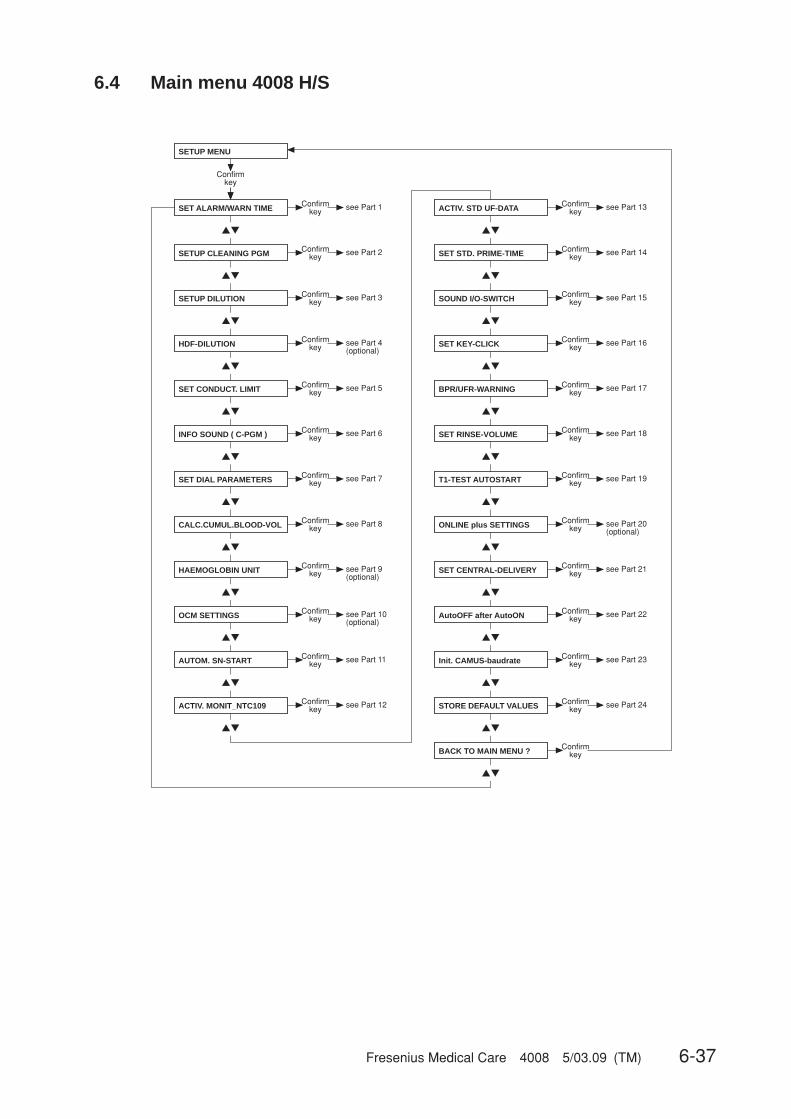
Fresenius Medical Care 4008 5/03.09 (TM) 6-37
6.4 Main menu 4008 H/S
▲▼
▲▼
▲▼
▲▼
▲▼
▲▼
▲▼
▲▼
▲▼
▲▼
▲▼
▲▼
▲▼
▲▼
▲▼
▲▼
▲▼
▲▼
▲▼
▲▼
▲▼
▲▼
▲▼
AutoOFF after AutoON
Init. CAMUS-baudrate
▲▼
▲▼
see Part 1
see Part 2
see Part 3
see Part 4(optional)
see Part 5
see Part 6
see Part 7
see Part 8
see Part 9(optional)
see Part 10(optional)
see Part 11
SETUP MENU
SET ALARM/WARN TIME
SETUP CLEANING PGM
INFO SOUND ( C-PGM )
SETUP DILUTION
SET CONDUCT. LIMIT
SET DIAL PARAMETERS
AUTOM. SN-START
HDF-DILUTION
HAEMOGLOBIN UNIT
CALC.CUMUL.BLOOD-VOL
OCM SETTINGS
Confirmkey
Confirmkey
Confirmkey
Confirmkey
Confirmkey
Confirmkey
Confirmkey
Confirmkey
Confirmkey
Confirmkey
Confirmkey
Confirmkey
see Part 12ConfirmkeyACTIV. MONIT_NTC109
BACK TO MAIN MENU ? Confirmkey
ACTIV. STD UF-DATA
SET STD. PRIME-TIME
SOUND I/O-SWITCH
SET CENTRAL-DELIVERY
T1-TEST AUTOSTART
SET RINSE-VOLUME
BPR/UFR-WARNING
SET KEY-CLICK
ONLINE plus SETTINGS
see Part 13Confirmkey
see Part 14Confirmkey
see Part 15Confirmkey
see Part 16Confirmkey
see Part 17Confirmkey
see Part 18Confirmkey
see Part 19Confirmkey
see Part 20(optional)
Confirmkey
see Part 21Confirmkey
see Part 22Confirmkey
see Part 23Confirmkey
see Part 24ConfirmkeySTORE DEFAULT VALUES
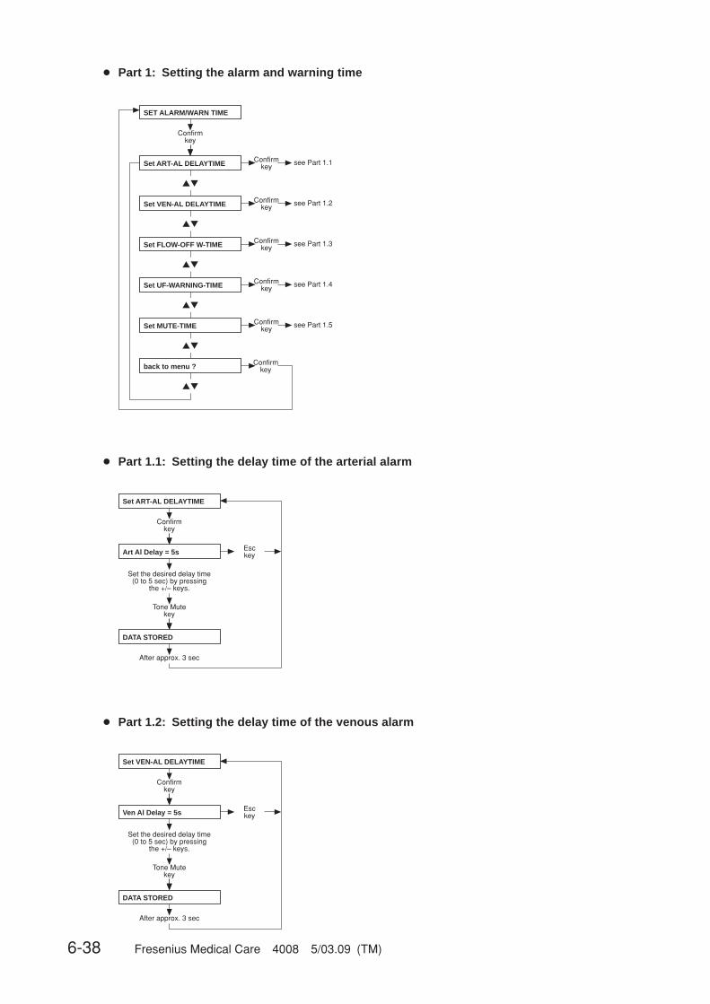
6-38 Fresenius Medical Care 4008 5/03.09 (TM)
● Part 1: Setting the alarm and warning time
▲▼
▲▼
▲▼
▲▼
▲▼
▲▼
SET ALARM/WARN TIME
Confirmkey
Set ART-AL DELAYTIME Confirmkey see Part 1.1
Set VEN-AL DELAYTIME Confirmkey see Part 1.2
Set FLOW-OFF W-TIME Confirmkey see Part 1.3
Set UF-WARNING-TIME Confirmkey see Part 1.4
Set MUTE-TIME Confirmkey see Part 1.5
back to menu ? Confirmkey
● Part 1.1: Setting the delay time of the arterial alarm
● Part 1.2: Setting the delay time of the venous alarm
Set ART-AL DELAYTIME
Confirmkey
Art Al Delay = 5s
Tone Mutekey
DATA STORED
After approx. 3 sec
Esckey
Set the desired delay time (0 to 5 sec) by pressing
the +/– keys.
Set VEN-AL DELAYTIME
Confirmkey
Ven Al Delay = 5s
Tone Mutekey
DATA STORED
After approx. 3 sec
Esckey
Set the desired delay time (0 to 5 sec) by pressing
the +/– keys.
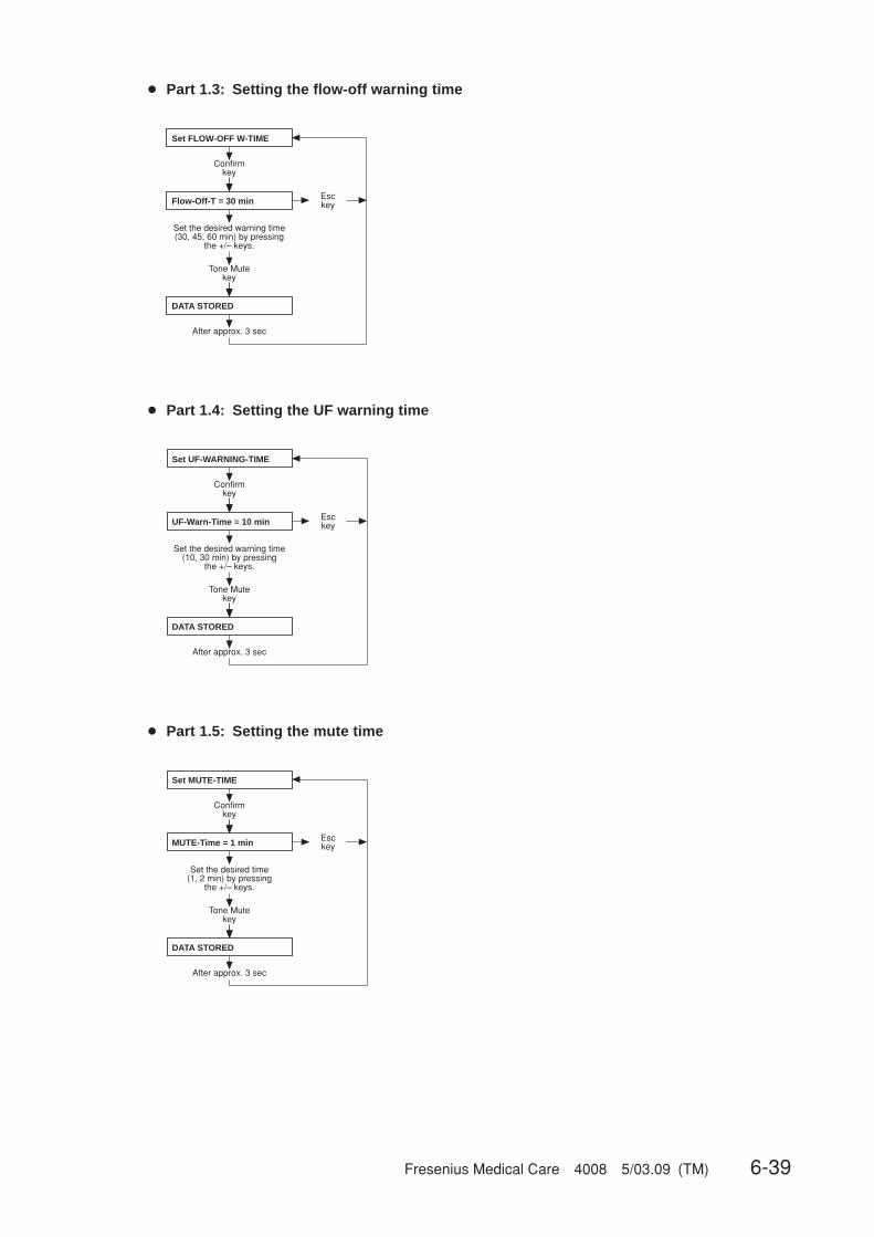
Fresenius Medical Care 4008 5/03.09 (TM) 6-39
● Part 1.3: Setting the flow-off warning time
Set FLOW-OFF W-TIME
Confirmkey
Flow-Off-T = 30 min
Tone Mutekey
DATA STORED
After approx. 3 sec
Esckey
Set the desired warning time (30, 45, 60 min) by pressing
the +/– keys.
● Part 1.4: Setting the UF warning time
● Part 1.5: Setting the mute time
Set UF-WARNING-TIME
Confirmkey
UF-Warn-Time = 10 min
Tone Mutekey
DATA STORED
After approx. 3 sec
Esckey
Set the desired warning time (10, 30 min) by pressing
the +/– keys.
Set MUTE-TIME
Confirmkey
MUTE-Time = 1 min
Tone Mutekey
DATA STORED
After approx. 3 sec
Esckey
Set the desired time (1, 2 min) by pressing
the +/– keys.

6-40 Fresenius Medical Care 4008 5/03.09 (TM)
● Part 2: Setting up the cleaning program
▲▼
▲▼
▲▼
SETUP CLEANING PGM
Confirmkey
CLEANING Times Confirmkey see Part 2.1
DEFAULT CLEANING Pgm Confirmkey see Part 2.2
back to menu ? Confirmkey
● Part 2.1: Cleaning times
▲▼
▲▼
▲▼
▲▼
▲▼
▲▼
▲▼
▲▼
▲▼
CLEANING Times
Confirmkey
Rinsing TIME Confirmkey see Part 2.1.1
Hotrinse TIME Confirmkey see Part 2.1.2
Disinfection TIME Confirmkey see Part 2.1.3
Rinsing Free TIME Confirmkey see Part 2.1.4
Hot-Disinf TIME Confirmkey see Part 2.1.5
back to menu ? Confirmkey
Mandatory Rinse TIME Confirmkey see Part 2.1.6
CITRO-Mandat-Ri-Time Confirmkey see Part 2.1.7
INTEGRATED-HR Time Confirmkey see Part 2.1.8
☞ NoteThe default values and the adjustable range for the cleaning times are notindicated, as they depend on the particular system options.
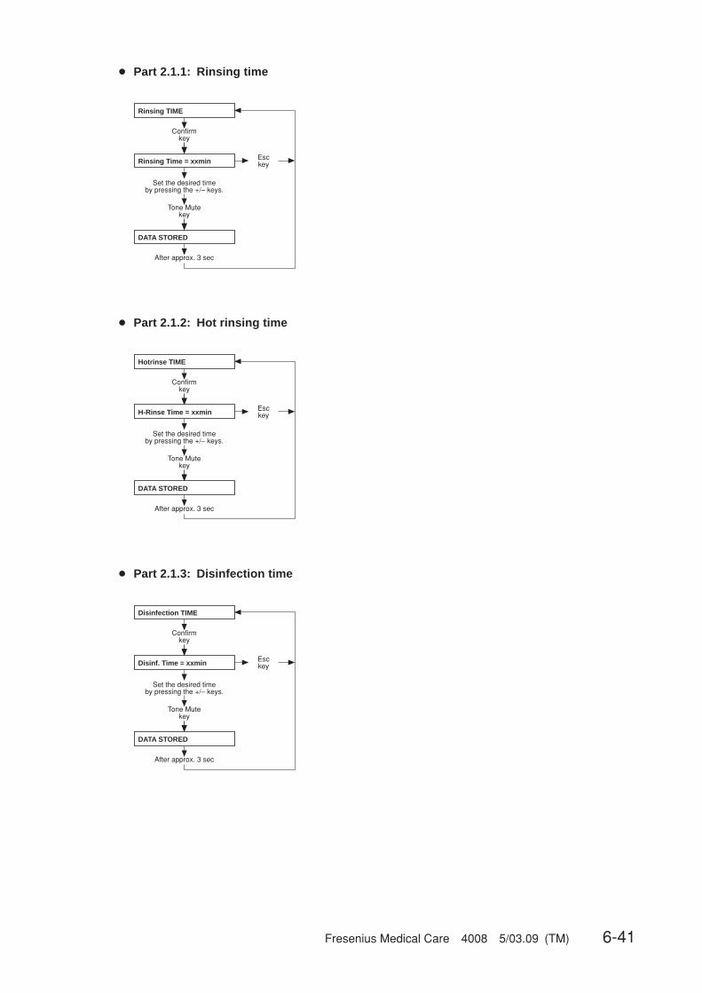
Fresenius Medical Care 4008 5/03.09 (TM) 6-41
● Part 2.1.1: Rinsing time
● Part 2.1.2: Hot rinsing time
● Part 2.1.3: Disinfection time
Esckey
Rinsing TIME
Confirmkey
Rinsing Time = xxmin
Tone Mutekey
DATA STORED
After approx. 3 sec
Set the desired time by pressing the +/– keys.
Hotrinse TIME
Confirmkey
H-Rinse Time = xxmin
Tone Mutekey
DATA STORED
After approx. 3 sec
Esckey
Set the desired time by pressing the +/– keys.
Disinfection TIME
Confirmkey
Disinf. Time = xxmin
Tone Mutekey
DATA STORED
After approx. 3 sec
Esckey
Set the desired time by pressing the +/– keys.

6-42 Fresenius Medical Care 4008 5/03.09 (TM)
● Part 2.1.4: Rinsing free time
● Part 2.1.5: Hot disinfection time
● Part 2.1.6: Mandatory rinse time
Rinsing Free TIME
Confirmkey
R.-Free Time = xmin
Tone Mutekey
DATA STORED
After approx. 3 sec
Esckey
Set the desired time by pressing the +/– keys.
Hot-Disinf TIME
Confirmkey
H-Disinf Time = xxmin
Tone Mutekey
DATA STORED
After approx. 3 sec
Esckey
Set the desired time by pressing the +/– keys.
Mandatory Rinse TIME
Confirmkey
M-Rinse Time = xxmin
Tone Mutekey
DATA STORED
After approx. 3 sec
Esckey
Set the desired time by pressing the +/– keys.
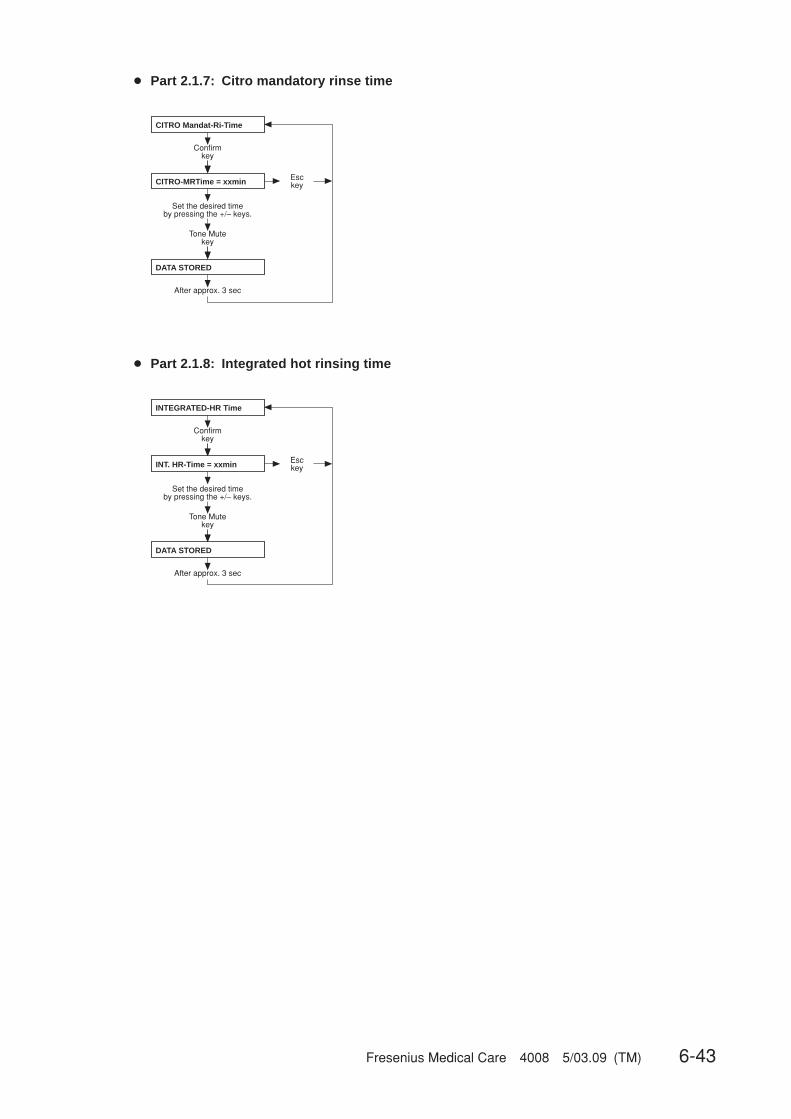
Fresenius Medical Care 4008 5/03.09 (TM) 6-43
● Part 2.1.7: Citro mandatory rinse time
● Part 2.1.8: Integrated hot rinsing time
INTEGRATED-HR Time
Confirmkey
INT. HR-Time = xxmin
Tone Mutekey
DATA STORED
After approx. 3 sec
Esckey
Set the desired time by pressing the +/– keys.
CITRO Mandat-Ri-Time
Confirmkey
CITRO-MRTime = xxmin
Tone Mutekey
DATA STORED
After approx. 3 sec
Esckey
Set the desired time by pressing the +/– keys.
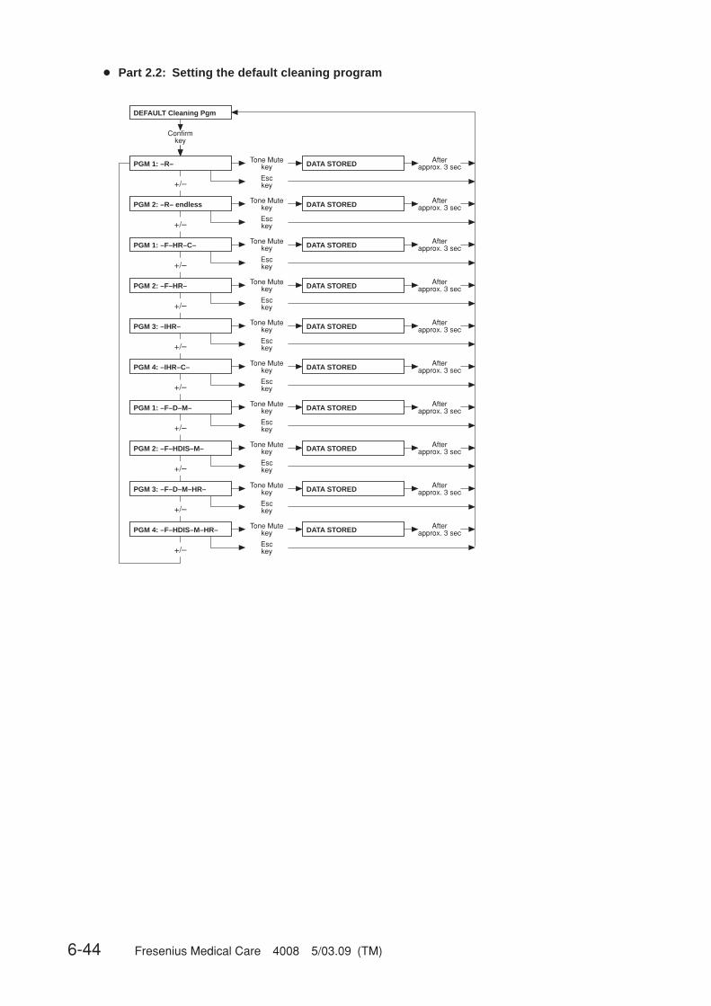
6-44 Fresenius Medical Care 4008 5/03.09 (TM)
● Part 2.2: Setting the default cleaning program
+/–
+/–
+/–
+/–
+/–
+/–
+/–
+/–
+/–
+/–
DEFAULT Cleaning Pgm
Confirmkey
PGM 1: –R– Tone Mutekey DATA STORED
Esckey
DATA STORED
DATA STORED
DATA STORED
Afterapprox. 3 sec
Afterapprox. 3 sec
Afterapprox. 3 sec
Afterapprox. 3 sec
DATA STORED Afterapprox. 3 sec
DATA STORED Afterapprox. 3 sec
DATA STORED Afterapprox. 3 sec
DATA STORED Afterapprox. 3 sec
Tone Mutekey
Esckey
Tone Mutekey
Esckey
Tone Mutekey
Esckey
Tone Mutekey
Esckey
Tone Mutekey
Esckey
Tone Mutekey
Esckey
Tone Mutekey
Esckey
PGM 2: –R– endless
PGM 1: –F–HR–C–
PGM 2: –F–HR–
PGM 3: –IHR–
PGM 1: –F–D–M–
PGM 2: –F–HDIS–M–
PGM 4: –F–HDIS–M–HR–
DATA STORED Afterapprox. 3 sec
Tone Mutekey
Esckey
PGM 3: –F–D–M–HR–
DATA STORED Afterapprox. 3 sec
Tone Mutekey
Esckey
PGM 4: –IHR–C–

Fresenius Medical Care 4008 5/03.09 (TM) 6-45
+/–
+/–
+/–
+/–
+/–
+/–
+/–
SETUP DILUTION
Confirmkey
Tone Mutekey DATA STORED
Esckey
DATA STORED
DATA STORED
DATA STORED
Afterapprox. 3 sec
Afterapprox. 3 sec
Afterapprox. 3 sec
Afterapprox. 3 sec
DATA STORED Afterapprox. 3 sec
Tone Mutekey
Esckey
Tone Mutekey
Esckey
Tone Mutekey
Esckey
Tone Mutekey
Esckey
DATA STORED Afterapprox. 3 sec
Tone Mutekey
Esckey
Confirmkey see Part 3.1
canister 1+34
1+35.83 ( NaCl 20 )
1+35.83 ( NaCl 26 )
1+35.83 ( Belgium )
canister 1+44 C
canister 1+44 ACF
VARIABLE SETTING
● Part 3: Mixing ratio with„NO central-delivery“, „central Bic“ (setting ➜ Part 21)
+/–
+/–
+/–
+/–
+/–
+/–
+/– +/–
+/–
+/–
+/–
SETUP DILUTION
Confirmkey
canister 1+34
1+35.83 (NaCl 20)
1+35.83 (NaCl 26)
1+35.83 ( Belgium )
canister 1+44 C
canister 1+44 ACF
VARIABLE SETTING
Tone Mutekey
Esckey
Tone Mutekey
Esckey
Tone Mutekey
Esckey
Tone Mutekey
Esckey
Tone Mutekey
Esckey
Tone Mutekey
Esckey
Confirmkey see Part 3.1
Afterapprox. 3 sec
Afterapprox. 3 sec
Afterapprox. 3 sec
Afterapprox. 3 sec
Afterapprox. 3 sec
Afterapprox. 3 sec
DATA STORED
DATA STORED
DATA STORED
DATA STORED
DATA STORED
DATA STORED
ACKNOWLEDGED
CDS 1+34
CDS 1+44 C
CDS 1+44 ACF
Tone Mutekey
Esckey
CDS 1+34
CDS 1+44 ACF
Tone Mutekey
Esckey
ACKNOWLEDGED
CDS 1+34
CDS 1+44 C
Tone Mutekey
Esckey
ACKNOWLEDGED
● Part 3: Mixing ratio with„central Acid“, „central Acid + Bic“ (setting ➜ Part 21)
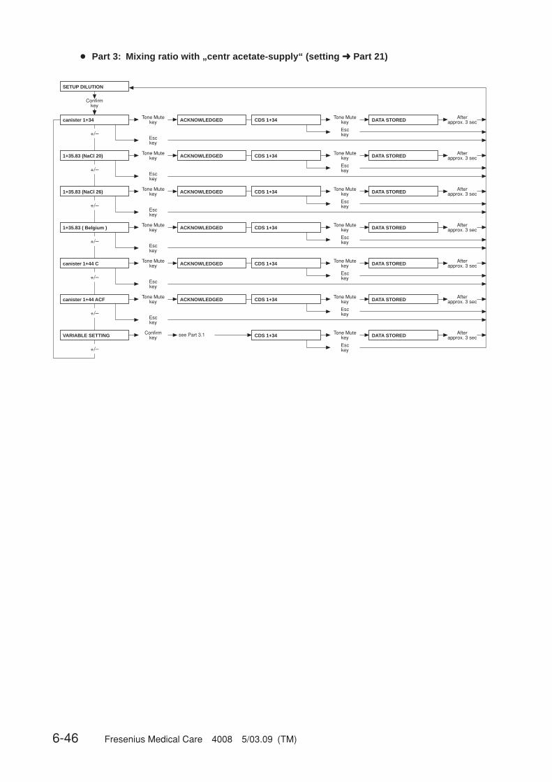
6-46 Fresenius Medical Care 4008 5/03.09 (TM)
+/–
+/–
+/–
+/–
+/–
+/–
+/–
SETUP DILUTION
Confirmkey
canister 1+34
1+35.83 (NaCl 20)
1+35.83 (NaCl 26)
1+35.83 ( Belgium )
canister 1+44 C
canister 1+44 ACF
VARIABLE SETTING
Tone Mutekey
Esckey
Afterapprox. 3 secDATA STOREDACKNOWLEDGED CDS 1+34 Tone Mute
key
Esckey
Tone Mutekey
Esckey
Afterapprox. 3 secDATA STOREDTone Mute
key
Esckey
Tone Mutekey
Esckey
Afterapprox. 3 secDATA STOREDTone Mute
key
Esckey
Tone Mutekey
Esckey
Afterapprox. 3 secDATA STOREDTone Mute
key
Esckey
Tone Mutekey
Afterapprox. 3 secDATA STOREDTone Mute
key
Esckey
Afterapprox. 3 secDATA STOREDTone Mute
key
Esckey
CDS 1+34
CDS 1+34
CDS 1+34
CDS 1+34
CDS 1+34
Esckey
Confirmkey see Part 3.1
Tone Mutekey
Afterapprox. 3 secDATA STOREDTone Mute
key
Esckey
CDS 1+34
Esckey
ACKNOWLEDGED
ACKNOWLEDGED
ACKNOWLEDGED
ACKNOWLEDGED
ACKNOWLEDGED
● Part 3: Mixing ratio with „centr acetate-supply“ (setting ➜ Part 21)

Fresenius Medical Care 4008 5/03.09 (TM) 6-47
● Part 3.1: Programmable mixing ratio (dilution)
+/–
SETUP DILUTION
Confirmkey
VARIABLE SETTING B-Comp[part]:0.800
Tone Mutekey
ACKNOWLEDGED
After approx. 3 sec
Set the desired value (0.800 – 2.500)
by pressing the +/– keys.
Esckey
RO[part] : 30.000
Tone Mutekey
ACKNOWLEDGED
After approx. 3 sec
Set the desired value (30.000 – 45.000)
by pressing the +/– keys.
Esckey
HCO3–[mmol]: 25
Tone Mutekey
ACKNOWLEDGED
After approx. 3 sec
Set the desired value (25 – 45)
by pressing the +/– keys.
Esckey
Na(B)[mmol]: 25
Tone Mutekey
ACKNOWLEDGED
After approx. 3 sec
Set the desired value (25 – 80)
by pressing the +/– keys.
Esckey
Confirmkey
CautionThe operator or technician is informed about his duty of care to enter the com-ponent parameters and settings correctly or to check them and to set the CDalarm window to the expected conductivity value.When using the programmable mixing ratio (dilution), make sure to use theright concentrate.Using a bibag® in combination with the programmable mixing ratio (dilution) isnot allowed.Only enter authorized, programmable mixing ratios (dilutions).

6-48 Fresenius Medical Care 4008 5/03.09 (TM)
● Part 4: Setting the HDF dilution – only for ON-LINE-HDF (option)
● Part 5: Setting the conductivity limit
+/–
+/–
HDF-DILUTION
Confirmkey
HDF-PRE-dilution DATA STORED
DATA STORED
Afterapprox. 3 sec
Afterapprox. 3 sec
Tone Mutekey
Esckey
Tone Mutekey
Esckey
HDF-POST-dilution
SET CONDUCT. LIMIT
Confirmkey
Cd Limit: 12.8 mS/cm
Tone Mutekey
DATA STORED
After approx. 3 sec
Esckey
Set the desired value (12.8 to 14.0 mS/cm)
by pressing the +/– keys.
● Part 6: Infosound cleaning program
+/–
+/–
INFO SOUND (C-PGM)
Confirmkey
Info-Sound: ON
Info-Sound: OFF
DATA STORED
DATA STORED
Afterapprox. 3 sec
Afterapprox. 3 sec
Tone Mutekey
Esckey
Tone Mutekey
Esckey

Fresenius Medical Care 4008 5/03.09 (TM) 6-49
● Part 7: Setting the dialysis parameters
▲▼
▲▼
▲▼
▲▼
SET DIAL PARAMETERS
Confirmkey
SET Flow Parameter Confirmkey see Part 7.1
SET Temp. Parameter Confirmkey see Part 7.2
SET Na/Bic Parameter Confirmkey see Part 7.3
back to menu ? Confirmkey
● Part 7.1: Setting the dialysate flow
SET Flow Parameter
Confirmkey
Flow[ml/min]: 500
Tone Mutekey
DATA STORED
After approx. 3 sec
Esckey
Set the desired value (300, 500, 800)
by pressing the +/– keys.OR
Value set in Dial
● Part 7.2: Setting the dialysate temperature
Confirmkey
Tone Mutekey
DATA STORED
After approx. 3 sec
Esckey
Set the desired value (35.0 – 39.0)
by pressing the +/– keys.OR
Value set in Dial
SET Temp. Parameter
Temp.[°C]: 37,0
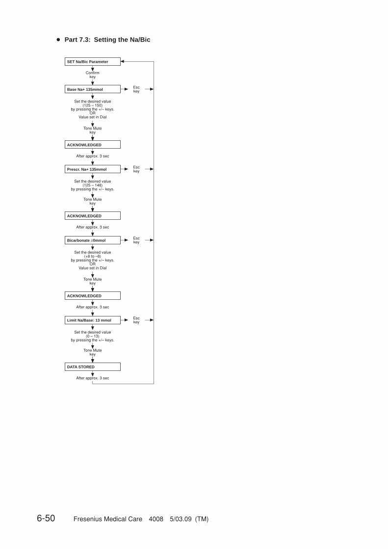
6-50 Fresenius Medical Care 4008 5/03.09 (TM)
● Part 7.3: Setting the Na/Bic
SET Na/Bic Parameter
Confirmkey
Base Na+ 135mmol
Tone Mutekey
ACKNOWLEDGED
After approx. 3 sec
Esckey
Set the desired value (125 – 150)
by pressing the +/– keys.OR
Value set in Dial
Prescr. Na+ 135mmol
Tone Mutekey
ACKNOWLEDGED
After approx. 3 sec
Esckey
Set the desired value (125 – 148)
by pressing the +/– keys.
Bicarbonate ±0mmol
Tone Mutekey
DATA STORED
After approx. 3 sec
Esckey
Set the desired value (+8 to –8)
by pressing the +/– keys.OR
Value set in Dial
ACKNOWLEDGED
After approx. 3 sec
Limit Na/Base: 13 mmol
Tone Mutekey
Esckey
Set the desired value (0 – 13)
by pressing the +/– keys.

Fresenius Medical Care 4008 5/03.09 (TM) 6-51
● Part 8: Cumulated blood volume
+/–
+/–
Confirmkey
Afterapprox. 3 sec
Afterapprox. 3 sec
Tone Mutekey
Esckey
Tone Mutekey
Esckey
CALC.CUMUL.BLOOD-VOL
during seq DIAL: YES
during seq DIAL: NO
DATA STORED
DATA STORED
● Part 9: Haemoglobin unit – only for BVM (option)
+/–
+/–
Confirmkey
Afterapprox. 3 sec
Afterapprox. 3 sec
Tone Mutekey
Esckey
Tone Mutekey
Esckey
DATA STORED
DATA STORED
HAEMOGLOBIN UNIT
g/dl
mmol/l
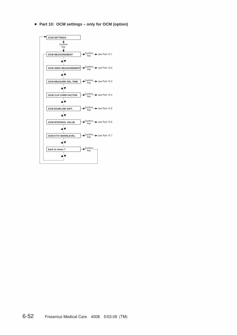
6-52 Fresenius Medical Care 4008 5/03.09 (TM)
● Part 10: OCM settings – only for OCM (option)
▲▼
▲▼
▲▼
▲▼
▲▼
▲▼
▲▼
▲▼
OCM SETTINGS
Confirmkey
OCM MEASUREMENT
OCM ZERO MEASUREMENT
OCM MEASURE DEL.TIME
OCM CLR CORR FACTOR
OCM BASELINE DIFF.
back to menu ?
OCM INTEGRAL VALUE
OCM KT/V WARNLEVEL
Confirmkey see Part 10.1
Confirmkey see Part 10.2
Confirmkey see Part 10.3
Confirmkey see Part 10.4
Confirmkey see Part 10.5
Confirmkey see Part 10.6
Confirmkey see Part 10.7
Confirmkey

Fresenius Medical Care 4008 5/03.09 (TM) 6-53
● Part 10.1: Activating the OCM measurement
+/–
+/–
Confirmkey
Afterapprox. 3 sec
Afterapprox. 3 sec
Tone Mutekey
Esckey
Tone Mutekey
Esckey
DATA STORED
DATA STORED
OCM MEASUREMENT
OCM Measurement: OFF
OCM Measurement: ON
(default value: OFF)
● Part 10.2: Activating the OCM zero measurement
+/–
+/–
Confirmkey
Afterapprox. 3 sec
Afterapprox. 3 sec
Tone Mutekey
Esckey
Tone Mutekey
Esckey
DATA STORED
DATA STORED
OCM ZERO MEASUREMENT
OCM Zero Measure:OFF
OCM Zero Measure:ON
(default value: ON)
☞ NoteIf the OCM zero measurement is set to “OFF”, the OCM option is deactivated.If the OCM option is reactivated (“ON”), an OCM pulse calibration must beperformed.
● Part 10.3: Setting the OCM measurement delay time
Confirmkey
Tone Mutekey
DATA STORED
After approx. 3 sec
Esckey
OCM MEASURE DEL.TIME
Delaytime: XX s
Press +/– to set the value indi-cated in the table on the right
(1 – 70 s)
System Time
4008 H with advanced 15 Sec4008 H hydraulics4008 H with ONLINEplus™ 65 Sec
4008 S with advanced 18 Sec4008 S hydraulics4008 S with ONLINEplus™ 67 Sec
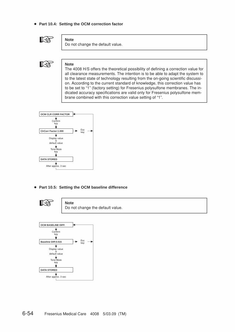
6-54 Fresenius Medical Care 4008 5/03.09 (TM)
● Part 10.4: Setting the OCM correction factor
☞ NoteDo not change the default value.
☞ NoteThe 4008 H/S offers the theoretical possibility of defining a correction value forall clearance measurements. The intention is to be able to adapt the system toto the latest state of technology resulting from the on-going scientific discussi-on. According to the current standard of knowledge, this correction value hasto be set to “1” (factory setting) for Fresenius polysulfone membranes. The in-dicated accuracy specifications are valid only for Fresenius polysulfone mem-brane combined with this correction value setting of “1”.
Confirmkey
Tone Mutekey
DATA STORED
After approx. 3 sec
Esckey
OCM CLR CORR FACTOR
ClrCorr Factor:1.000
Display value is
default value
● Part 10.5: Setting the OCM baseline difference
☞ NoteDo not change the default value.
Confirmkey
Tone Mutekey
DATA STORED
After approx. 3 sec
Esckey
OCM BASELINE DIFF.
Baseline Diff:0.015
Display value is
default value

Fresenius Medical Care 4008 5/03.09 (TM) 6-55
● Part 10.6: Setting the OCM integral value
● Part 10.7: Setting the OCM Kt/V warning level
Confirmkey
Tone Mutekey
DATA STORED
After approx. 3 sec
Esckey
OCM KT/V WARNLEVEL
Kt/V Warnlevel: 85 %
Press +/– to set the warning level (default value 85)Range 0 – 99%0 = no warning
☞ NoteDo not change the default value.
Confirmkey
Tone Mutekey
DATA STORED
After approx. 3 sec
Esckey
OCM INTEGRAL VALUE
Integral Value: 55
Display value is
default value

6-56 Fresenius Medical Care 4008 5/03.09 (TM)
● Part 11: Automatic Single-Needle start
● Part 12: Activation of Monit_NTC 109
+/–
+/–
DATA STORED
DATA STORED
Confirmkey
Afterapprox. 3 sec
Afterapprox. 3 sec
Tone Mutekey
Esckey
Tone Mutekey
Esckey
AUTOM. SN-START
autom. SN: OFF
autom. SN: ON
+/–
+/–
DATA STORED
DATA STORED
Confirmkey
Afterapprox. 3 sec
Afterapprox. 3 sec
Tone Mutekey
Esckey
Tone Mutekey
Esckey
ACTIV. MONIT_NTC109
MONIT_NTC109: YES
MONIT_NTC109: NO
● Part 13: Activation of standard UF data
+/–
+/–
ACTIV. STD UF-DATA
DATA STORED
DATA STORED
Confirmkey
Afterapprox. 3 sec
Afterapprox. 3 sec
Tone Mutekey
Esckey
Tone Mutekey
Esckey
std UF-DATA: NO
std UF-DATA: YES
UF-Rate:UF-Goal:Time Left:
750 ml/h3000 ml4 h

Fresenius Medical Care 4008 5/03.09 (TM) 6-57
● Part 14: Setting the priming time
SET STD. PRIME-TIME
Confirmkey
Prime-Time = 2min
Tone Mutekey
DATA STORED
After approx. 3 sec
Esckey
Set the desired time (1 to 5 min) by pressing
the +/– keys.
● Part 15: Warning sound I/O key
+/–
+/–
SOUND I/O SWITCH
Confirmkey
I/O-Warnsound: ON
I/O-Warnsound: OFF
DATA STORED
DATA STORED
Afterapprox. 3 sec
Afterapprox. 3 sec
Tone Mutekey
Esckey
Tone Mutekey
Esckey
● Part 16: Setting the key-click
+/–
+/–
SET KEY-CLICK
Confirmkey
key-click: ON
key-click: OFF
DATA STORED
DATA STORED
Afterapprox. 3 sec
Afterapprox. 3 sec
Tone Mutekey
Esckey
Tone Mutekey
Esckey

6-58 Fresenius Medical Care 4008 5/03.09 (TM)
● Part 18: Setting the rinse volume
SET RINSE–VOLUME
Confirmkey
RINSE-VOL: 1000 ml
Tone Mutekey
DATA STORED
After approx. 3 sec
Esckey
Set the desired rinse volume(0 to 5000 ml
in 100 ml increments)by pressing the +/– keys.
● Part 19: T1-Test Autostart
+/–
+/–
DATA STORED
DATA STORED
Confirmkey
Afterapprox. 3 sec
Afterapprox. 3 sec
Tone Mutekey
Esckey
Tone Mutekey
Esckey
T1-TEST AUTOSTART
T1-T. Autostart: OFF
T1-T. Autostart: ON
● Part 17: Setting the BPR/UFR warning
+/–
+/–
BPR/UFR–WARNING
Confirmkey
BPR/UFR–Warning: ON
BPR/UFR–Warning: OFF
DATA STORED
DATA STORED
Afterapprox. 3 sec
Afterapprox. 3 sec
Tone Mutekey
Esckey
Tone Mutekey
Esckey

Fresenius Medical Care 4008 5/03.09 (TM) 6-59
● Part 20: ONLINEplusplusplusplusplus™ settings – only for ONLINEplusplusplusplusplus™ (option)
▲▼
▲▼
▲▼
▲▼
▲▼
Confirmkey
back to menu ?
Confirmkey see Part 20.1
Confirmkey see Part 20.3
Confirmkey see Part 20.2
Confirmkey see Part 20.4
Confirmkey
ONLINE plus SETTINGS
ONLINE plus HD
ONLINE plus HDF
ONLINE plus HF
ONLINE plus MISC.
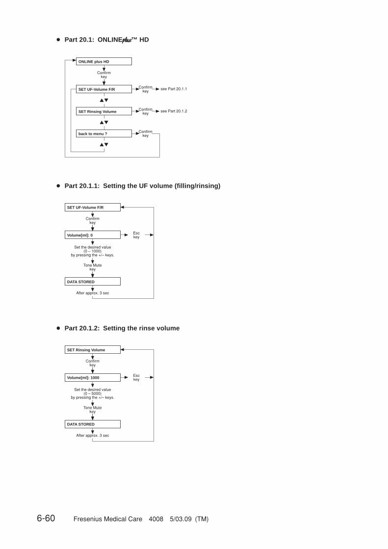
6-60 Fresenius Medical Care 4008 5/03.09 (TM)
● Part 20.1: ONLINEplusplusplusplusplus™ HD
▲▼
▲▼
▲▼
Confirmkey
Confirmkey see Part 20.1.1
back to menu ?
Confirmkey see Part 20.1.2
Confirmkey
ONLINE plus HD
SET UF-Volume F/R
SET Rinsing Volume
● Part 20.1.1: Setting the UF volume (filling/rinsing)
Confirmkey
Tone Mutekey
DATA STORED
After approx. 3 sec
Esckey
Set the desired value (0 – 1000)
by pressing the +/– keys.
SET UF-Volume F/R
Volume[ml]: 0
● Part 20.1.2: Setting the rinse volume
Confirmkey
Tone Mutekey
DATA STORED
After approx. 3 sec
Esckey
Set the desired value (0 – 5000)
by pressing the +/– keys.
SET Rinsing Volume
Volume[ml]: 1000

Fresenius Medical Care 4008 5/03.09 (TM) 6-61
● Part 20.2: ONLINEplusplusplusplusplus™ HDF
▲▼
▲▼
▲▼
▲▼
SET UF-Volume F/R
SET Rinsing Volume
Confirmkey
Confirmkey see Part 20.2.1
back to menu ?
Confirmkey see Part 20.2.2
Confirmkey
Confirmkey see Part 20.2.3SET Substit.-Volume
ONLINE plus HDF
● Part 20.2.1: Setting the UF volume (filling/rinsing)
Confirmkey
Tone Mutekey
DATA STORED
After approx. 3 sec
Esckey
Set the desired value (0 – 1000)
by pressing the +/– keys.
SET UF-Volume F/R
Volume[ml]: 500
● Part 20.2.2: Setting the rinse volume
Confirmkey
Tone Mutekey
DATA STORED
After approx. 3 sec
Esckey
Set the desired value (0 – 5000)
by pressing the +/– keys.
SET Rinsing Volume
Volume[ml]: 1000

6-62 Fresenius Medical Care 4008 5/03.09 (TM)
● Part 20.2.3: Setting the substituate volume
Confirmkey
Tone Mutekey
DATA STORED
After approx. 3 sec
Esckey
Set the desired value (0 – 210)
by pressing the +/– keys.
SET Substit.-Volume
Volume[l]: 12

Fresenius Medical Care 4008 5/03.09 (TM) 6-63
● Part 20.3: ONLINEplusplusplusplusplus™ HF
▲▼
▲▼
▲▼
▲▼
SET UF-Volume F/R
SET Rinsing Volume
Confirmkey
Confirmkey see Part 20.3.1
back to menu ?
Confirmkey see Part 20.3.2
Confirmkey
Confirmkey see Part 20.3.3SET Substit.-Volume
ONLINE plus HF
● Part 20.3.1: Setting the UF volume (filling/rinsing)
Confirmkey
Tone Mutekey
DATA STORED
After approx. 3 sec
Esckey
Set the desired value (0 – 5000)
by pressing the +/– keys.
SET UF-Volume F/R
Volume[ml]: 1000
● Part 20.3.2: Setting the rinse volume
Confirmkey
Tone Mutekey
DATA STORED
After approx. 3 sec
Esckey
Set the desired value (0 – 5000)
by pressing the +/– keys.
SET Rinsing Volume
Volume[ml]: 1000

6-64 Fresenius Medical Care 4008 5/03.09 (TM)
● Part 20.3.3: Setting the substituate volume
Confirmkey
Tone Mutekey
DATA STORED
After approx. 3 sec
Esckey
Set the desired value (0 – 210)
by pressing the +/– keys.
SET Substit.-Volume
Volume[l]: 20

Fresenius Medical Care 4008 5/03.09 (TM) 6-65
● Part 20.4: ONLINEplusplusplusplusplus™ miscellaneous
▲▼
▲▼
Confirmkey
Confirmkey see Part 20.4.1
back to menu ? Confirmkey
ONLINE plus MISC.
SET Reinf.-Volume
● Part 20.4.1: Setting the reinfusion volume
Confirmkey
Tone Mutekey
DATA STORED
After approx. 3 sec
Esckey
Set the desired value (90 – 480)
by pressing the +/– keys.
SET Reinf.-Volume
Volume[ml]: 240

6-66 Fresenius Medical Care 4008 5/03.09 (TM)
● Part 21: Setting the parameters for central delivery system
☞ NoteCentral delivery is not available for the 3mix option.
+/–
+/–
+/–
+/–
+/–
SET CENTRAL-DELIVERY
Confirmkey
NO central-delivery
central Bic
DATA STORED
DATA STORED
central Acid DATA STORED
central Acid + Bic DATA STORED
Afterapprox. 3 sec
Afterapprox. 3 sec
Afterapprox. 3 sec
Afterapprox. 3 sec
centr acetate-supply DATA STORED Afterapprox. 3 sec
Tone Mutekey
Esckey
Tone Mutekey
Esckey
Tone Mutekey
Esckey
Tone Mutekey
Esckey
Tone Mutekey
Esckey
SETUP DILUTION
SETUP DILUTION
SETUP DILUTION
SETUP DILUTION
Afterapprox. 3 sec
Afterapprox. 3 sec
Afterapprox. 3 sec
Afterapprox. 3 sec
SETUP DILUTION Afterapprox. 3 sec
● Part 22: AutoOFF after AutoON
AutoOFF after AutoON
Confirmkey
Auto OFF: OFF DATA STORED Afterapprox. 3 sec
Auto OFF: ON DATA STORED
+/–
Tone Mutekey
Esckey
+/–
Tone Mutekey
Esckey
Afterapprox. 3 sec
● Part 23: CAMUS-baudrate
Init. CAMUS-baudrate
baudrate: 2400 baud
baudrate: 9600 baud
+/–
+/–
Confirmkey
DATA STORED Afterapprox. 3 sec
DATA STORED
Tone Mutekey
Esckey
Tone Mutekey
Esckey
Afterapprox. 3 sec

Fresenius Medical Care 4008 5/03.09 (TM) 6-67
● Part 24: Storing the default values
STORE DEFAULT VALUES
Confirmkey
Press ALARMTONE MUTE
DATA STORED
After approx. 3 sec
Esckey
Store the default values
by pressing the Tone Mute key.

6-68 Fresenius Medical Care 4008 5/03.09 (TM)
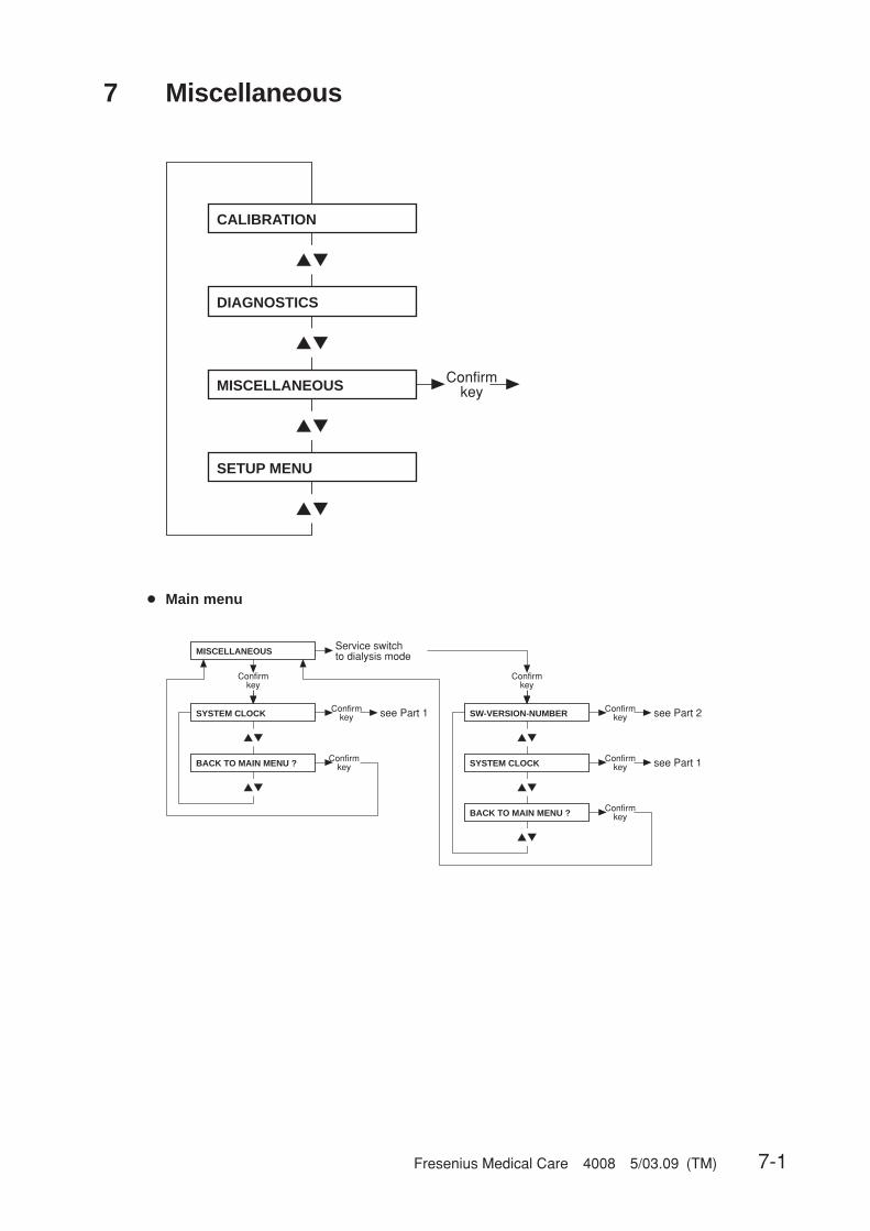
Fresenius Medical Care 4008 5/03.09 (TM) 7-1
7 Miscellaneous
▲▼
▲▼
▲▼
▲▼
Confirmkey
CALIBRATION
DIAGNOSTICS
MISCELLANEOUS
SETUP MENU
● Main menu
▲▼
▲▼ ▲▼
▲▼
▲▼
Confirmkey
Confirmkey see Part 1
Confirmkey
Service switchto dialysis mode
Confirmkey
Confirmkey see Part 1
Confirmkey see Part 2
Confirmkey
MISCELLANEOUS
SYSTEM CLOCK
BACK TO MAIN MENU ? SYSTEM CLOCK
BACK TO MAIN MENU ?
SW-VERSION-NUMBER
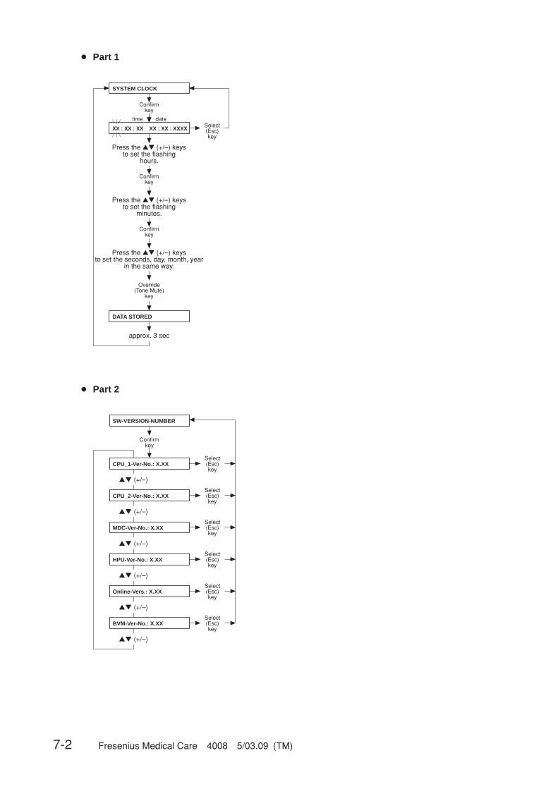
7-2 Fresenius Medical Care 4008 5/03.09 (TM)
● Part 1
XX : XX : XX XX : XX : XXXX
Press the ▲▼ (+/–) keysto set the flashing
minutes.
Press the ▲▼ (+/–) keysto set the seconds, day, month, year
in the same way.
Confirmkey
Select(Esc)key
Press the ▲▼ (+/–) keysto set the flashing
hours.
approx. 3 sec
Override (Tone Mute)
key
Confirmkey
Confirmkey
datetime
SYSTEM CLOCK
DATA STORED
● Part 2
▲▼ (+/–)
▲▼ (+/–)
▲▼ (+/–)
▲▼ (+/–)
▲▼ (+/–)
▲▼ (+/–)
SW-VERSION-NUMBER
CPU_1-Ver-No.: X.XX
CPU_2-Ver-No.: X.XX
MDC-Ver-No.: X.XX
HPU-Ver-No.: X.XX
Online-Vers.: X.XX
BVM-Ver-No.: X.XX
Confirm key
Select(Esc)key
Select(Esc)key
Select(Esc)key
Select(Esc)key
Select(Esc)key
Select(Esc)key
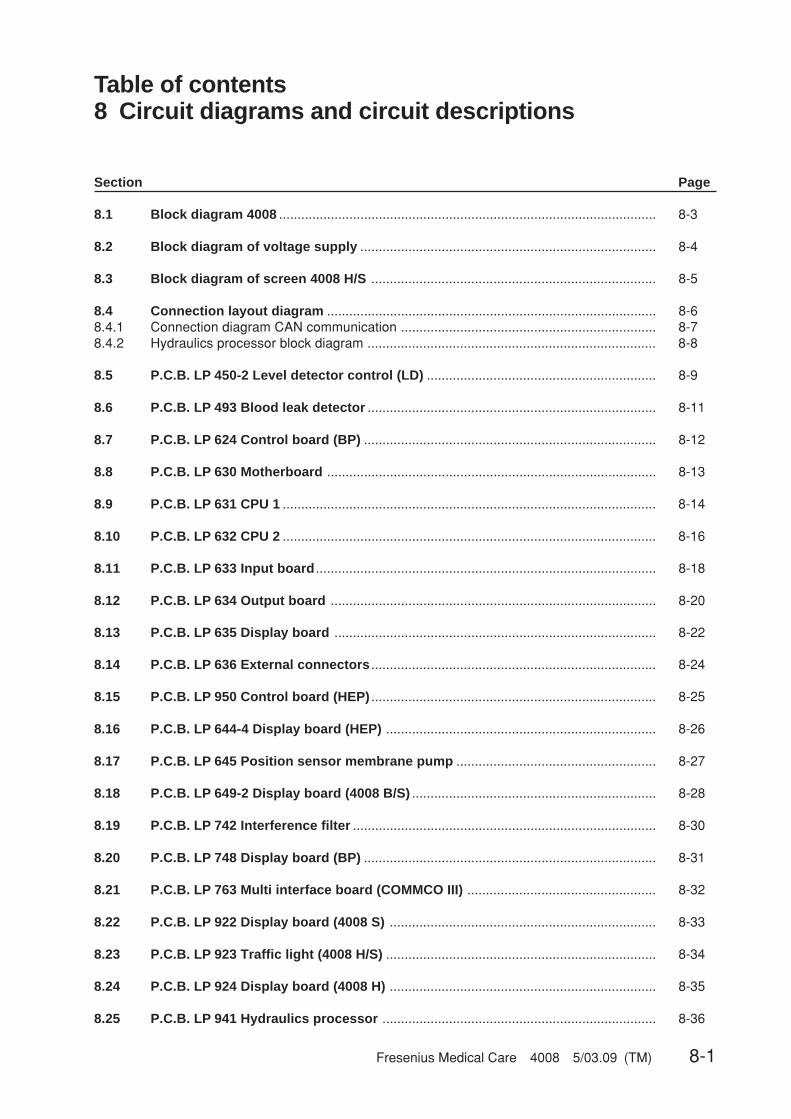
Fresenius Medical Care 4008 5/03.09 (TM) 8-1
Table of contents8 Circuit diagrams and circuit descriptions
Section Page
8.1 Block diagram 4008 ...................................................................................................... 8-3
8.2 Block diagram of voltage supply ................................................................................ 8-4
8.3 Block diagram of screen 4008 H/S ............................................................................. 8-5
8.4 Connection layout diagram ......................................................................................... 8-68.4.1 Connection diagram CAN communication ..................................................................... 8-78.4.2 Hydraulics processor block diagram .............................................................................. 8-8
8.5 P.C.B. LP 450-2 Level detector control (LD) .............................................................. 8-9
8.6 P.C.B. LP 493 Blood leak detector .............................................................................. 8-11
8.7 P.C.B. LP 624 Control board (BP) ............................................................................... 8-12
8.8 P.C.B. LP 630 Motherboard ......................................................................................... 8-13
8.9 P.C.B. LP 631 CPU 1 ..................................................................................................... 8-14
8.10 P.C.B. LP 632 CPU 2 ..................................................................................................... 8-16
8.11 P.C.B. LP 633 Input board ............................................................................................ 8-18
8.12 P.C.B. LP 634 Output board ........................................................................................ 8-20
8.13 P.C.B. LP 635 Display board ....................................................................................... 8-22
8.14 P.C.B. LP 636 External connectors ............................................................................. 8-24
8.15 P.C.B. LP 950 Control board (HEP) ............................................................................. 8-25
8.16 P.C.B. LP 644-4 Display board (HEP) ......................................................................... 8-26
8.17 P.C.B. LP 645 Position sensor membrane pump ...................................................... 8-27
8.18 P.C.B. LP 649-2 Display board (4008 B/S) .................................................................. 8-28
8.19 P.C.B. LP 742 Interference filter .................................................................................. 8-30
8.20 P.C.B. LP 748 Display board (BP) ............................................................................... 8-31
8.21 P.C.B. LP 763 Multi interface board (COMMCO III) ................................................... 8-32
8.22 P.C.B. LP 922 Display board (4008 S) ........................................................................ 8-33
8.23 P.C.B. LP 923 Traffic light (4008 H/S) ......................................................................... 8-34
8.24 P.C.B. LP 924 Display board (4008 H) ........................................................................ 8-35
8.25 P.C.B. LP 941 Hydraulics processor .......................................................................... 8-36

8-2 Fresenius Medical Care 4008 5/03.09 (TM)
Section Page
8.26 Heater board (power supply unit 4008) ...................................................................... 8-37
8.27 Power board (power supply unit 4008) ...................................................................... 8-38

Fresenius Medical Care 4008 5/03.09 (TM) 8-3
8.1 Block diagram 4008
LP
634
Ou
tpu
tb
oar
d
LP
633
Inp
ut
bo
ard
+5V
+12
V+
5V+
12V
LP
631
CP
U 1
LP
632
CP
U 2
+5V
+12
V WD
-Set
WD
-Res
et
LP
635
LP
649
LP
922
LP
924
serie
lle
Sch
nitts
telle
seria
l in
terf
ace
Wat
chdo
g-A
usga
ngW
atch
dog
outp
ut
+5V
Hyd
rau
likH
ydra
ulic
Ein
sch
üb
eM
od
ule
s
+5V
+24
V_S
W
+24
V_S
W
+12
V
+24
V_S
W
+12
V
+24
V_E
M
PW
R_W
D
+12
V
Net
ztei
l40
08
Po
wer
S
up
ply
4008
Po
wer
Bo
ard
Hea
ter
Bo
ard
+5V
+24
V_S
W
+24
V_E
M
+12
V
230V
Akk
uB
atte
ry
zum
Dis
pla
yto
dis
pla
y
4008
:40
08 B
:40
08 S
:40
08 H
:
Dis
pla
yb
oar
d
24V
_US
+24
V_U
S
Wat
chdo
g
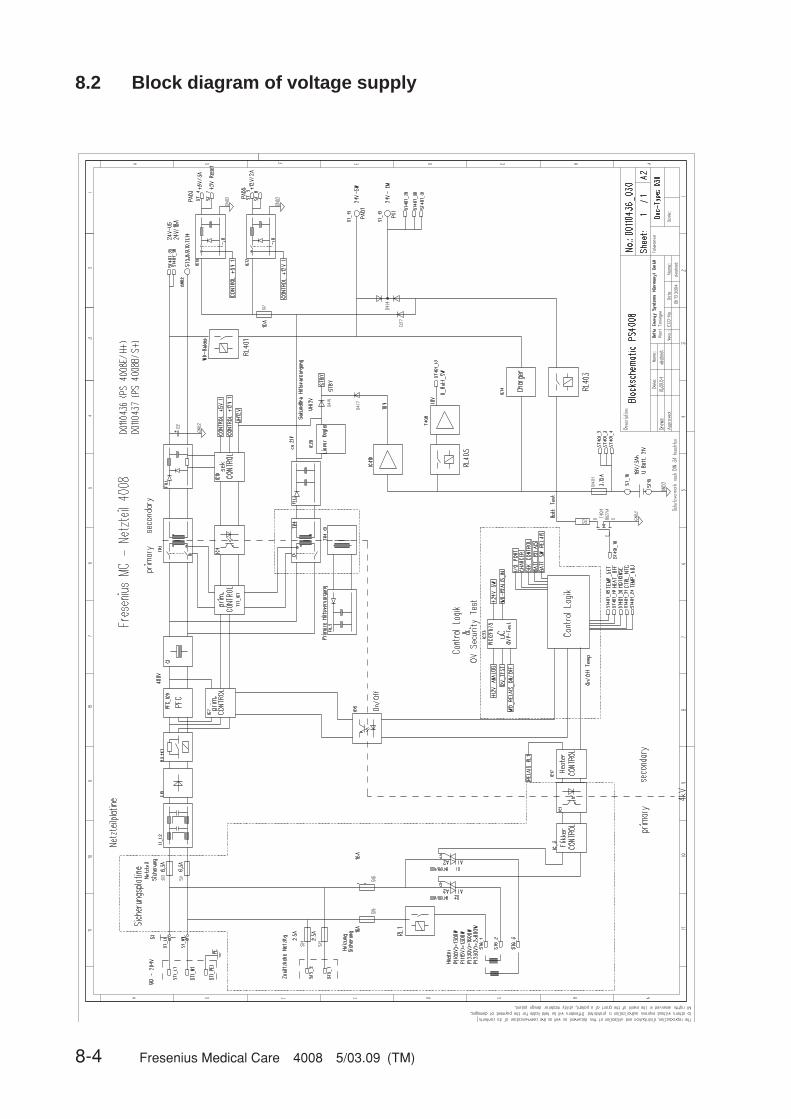
8-4 Fresenius Medical Care 4008 5/03.09 (TM)
8.2 Block diagram of voltage supply

Fresenius Medical Care 4008 5/03.09 (TM) 8-5
8.3 Block diagram of screen 4008 H/S
CP
U
RO
M
RS
232
Vid
eo
Contr
oller
Vid
eo
DR
AM
Backlight
Invert
er
RA
M
CP
U
RO
M
RS
232
RA
M
CP
U
RO
M
Speic
her
RS
232
RA
M
Speic
her
RS
232
Pow
er
logic
LP
647
(4008S
)
LP
639
(4008H
)
MD
C-B
oard
Moth
erb
oard
LP
630
CP
UII
LP
63
2
CP
UIL
P6
31
X639
Pow
er
Supply
24V
_U
S
24V_US
U-ACCU
Adress-/Databus
24V
_U
S
RS
23
2
RS232
TF
T-D
ispla
yD
ispla
yboard
LP
922
(4008S
)
LP
924
(4008H
)
Tra
fic
Lig
ht
LP
923
UB
acklight
Backlight
Vid
eo
Sig
nal

8-6 Fresenius Medical Care 4008 5/03.09 (TM)
8.4 Connection layout diagramX
A1
UF
-Pum
p 22
Flo
w p
ump
21D
egas
sing
pum
p 29
Air
sepa
ratio
n pu
mp
97X
A2
Val
ves
V24
V24
B V
26 V
30 V
41 V
43V
84 V
91 V
112
XA
3 B
alan
cing
cha
mbe
r va
lves
V31
–V38
Val
ves
V86
V87
XA
4C
CS
V99
V10
0 V
102
V10
4 V
126
V13
0X
A5
V18
3 V
188
V18
9 V
9C
ompr
esso
r 18
5C
O1
Con
cent
rate
pum
pB
I1B
icar
bona
te p
ump
XR
1O
CM
_NT
C 4
XR
2V
84 S
enso
rX
R3
Bib
ag p
ress
ure
tran
sduc
erX
2N
TC
2X
3N
TC
3X
5F
loat
sw
itch
X6
Leve
l sen
sor
6X
7C
ondu
ctiv
ity m
easu
ring
cell
X8
Dia
lysa
te p
ress
ure
tran
sduc
er 1
X9
Ree
d K
onta
kt 1
0 K
onze
ntra
tX
10P
ress
ure
switc
h C
CS
X11
Bib
agX
12B
ibag
NT
C 1
33X
13B
ibag
con
duct
ivity
mea
surin
g ce
llX
14N
TC
109
X15
OC
M c
ondu
ctiv
ity m
easu
ring
cell
110
XS
1D
ialy
sate
pre
ssur
e tr
ansd
ucer
2(1
82)
XS
2N
CX
S3
NC
XS
4N
CX
S5
Leve
l sen
sor
conc
entr
ate
202
XS
6N
TC
IND
I 308
XS
7IN
DI c
ondu
ctiv
ity m
easu
ring
cell
309
Sta
rtS
top
Rat
e: m
l/min
(Ø: m
m)
Sta
rtS
top
Rat
e: m
l/h(B
olus
: ml)
Bol
us
Rat
e
(
:h.m
in)
Pve
n.
X 6
35
X 639A
X 631X 632
X 633RX 633L
X H
DF
X 634RX 634L
X 6
37C
X 6
37B
X63Z
X D
IAG
X 3
48A
X 3
48V
X 3
50X
351
X S
HU
NT
X 6
36
X ACCU
X PWR
LP
630
Mo
ther
bo
ard
LP
636
Ext
ern
I/O Akk
uA
ccu
Net
ztei
l40
08P
ow
erS
up
ply
4008
Dia
gn
ose
Dia
gn
osi
sL
P 6
24X
348
LP
624
X 3
48L
P 6
43-3
LP
950
ST
1
LP
450
LP
450
-2X
351
Sta
rtS
top
Rat
e: m
l/min
(Ø: m
m)
Art
SN
Ku
rz-
sch
luß
-te
ilS
hu
nt
inte
rlo
ck
Pum
pen
/ Pum
ps
LP 6
32C
PU
2
LP 6
31C
PU
1
LP 6
33In
put
boar
d
LP 6
34O
utpu
tbo
ard
Dis
pla
yb
oar
d
X C
AN
X 6
37A
X A
CD
A
X C
AN
X R
S
LP 7
63M
ulti
Inte
rfac
eB
oard
X 8
2
Pum
pen
X C
1
Ven
tile
CO
1
Con
c.P.
BI1
Bic
.P.
X A
5X
A1
X A
2
X A
6X
A4
X A
3
N.C
.
X A
7
Sen
sore
n
X R
1
X 1
5
X 1
4
X 1
3
X 1
2
X 1
1
X 1
0
OC
M_N
TC
4
OC
M_L
F11
0
NT
C10
9
LF-B
ibag
108
Bib
ag N
TC
107
Bib
ag
ZK
V P
SW
X 2
X 3
X 5
X 6
X 7
X 8
X 9
NT
C2
NT
C3
FL-
Sw
itch
5
Niv
eau
6
LF 7
P-D
ial 1
(9)
Ree
dk. 1
0
X S
1
X S
2
X S
3
X S
4
X S
5
X S
6
X S
7
P-D
ial 2
NC
NC N
C
Niv
eau
Kon
z.
NT
C30
8
LF30
9
X 1
6
X B
1
X 1
7V
erte
iler-
plat
ine
Dis
trib
utio
nbo
ard
Blu
tleck
dete
ktor
Blo
od L
eak
Det
ecto
r
X R
3
X R
2
Bib
ag S
W
V89
Sen
s.
X 1
CA
N
LP
941
Was
sert
eilr
ech
ner
/ H
ydra
ulic
Pro
cess
ing
Un
it
Ven
tile
/ Val
ves
Sen
sore
n / S
enso
rs
X 1
/774
X 6
/928
X M
9
LP
928
/774
CA
N-B
US
Ver
teile
rC
AN
-BU
S D
istr
ibu
tio
n
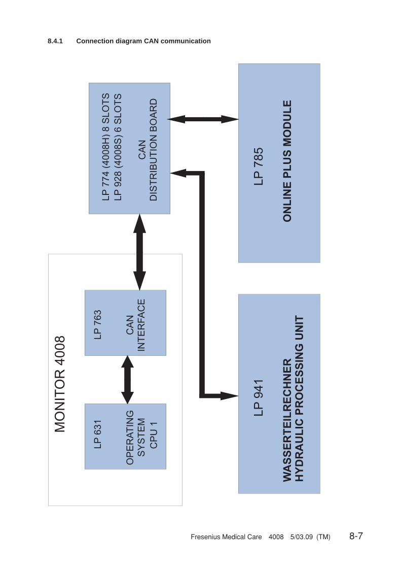
Fresenius Medical Care 4008 5/03.09 (TM) 8-7
8.4.1 Connection diagram CAN communication

8-8 Fresenius Medical Care 4008 5/03.09 (TM)
8.4.2 Hydraulics processor block diagram
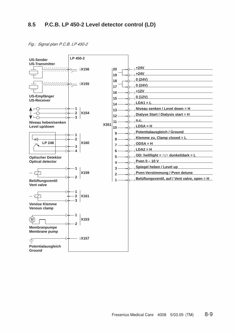
Fresenius Medical Care 4008 5/03.09 (TM) 8-9
8.5 P.C.B. LP 450-2 Level detector control (LD)
Fig.: Signal plan P.C.B. LP 450-2
US-SenderUS-Transmitter
US-EmpfängerUS-Receiver
Niveau heben/senkenLevel up/down
123
X156
X155
X154
Optischer DetektorOptical detector
LP 248
12
34
X160
123
X161
Venöse KlemmeVenous clamp
1
2X159
BelüftungsventilVent valve
1
2X153
MembranpumpeMembrane pump
M
X157
PotentialausgleichGround
20
19
+24V
+24V
18
17
0 (24V)
0 (24V)
16
15
+12V
0 (12V)
14
13
LDA1 = L
Niveau senken / Level down = H
12
11
Dialyse Start / Dialysis start = H
n.c.
10
9
LDSA = H
Potentialausgleich / Ground
8
7
Klemme zu, Clamp closed = L
ODSA = H
6
5
LDA2 = H
OD: hell/light =
4
3
Pven 0 – 10 V
Spiegel heben / Level up
2
1
Pven-Verstimmung / Pven detune
Belüftungsventil, auf / Vent valve, open = H
dunkel/dark = L
X351
LP 450-2

8-10 Fresenius Medical Care 4008 5/03.09 (TM)
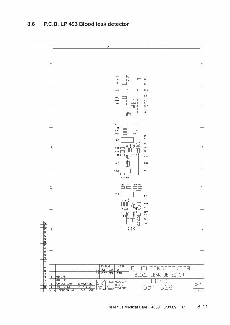
Fresenius Medical Care 4008 5/03.09 (TM) 8-11
8.6 P.C.B. LP 493 Blood leak detector
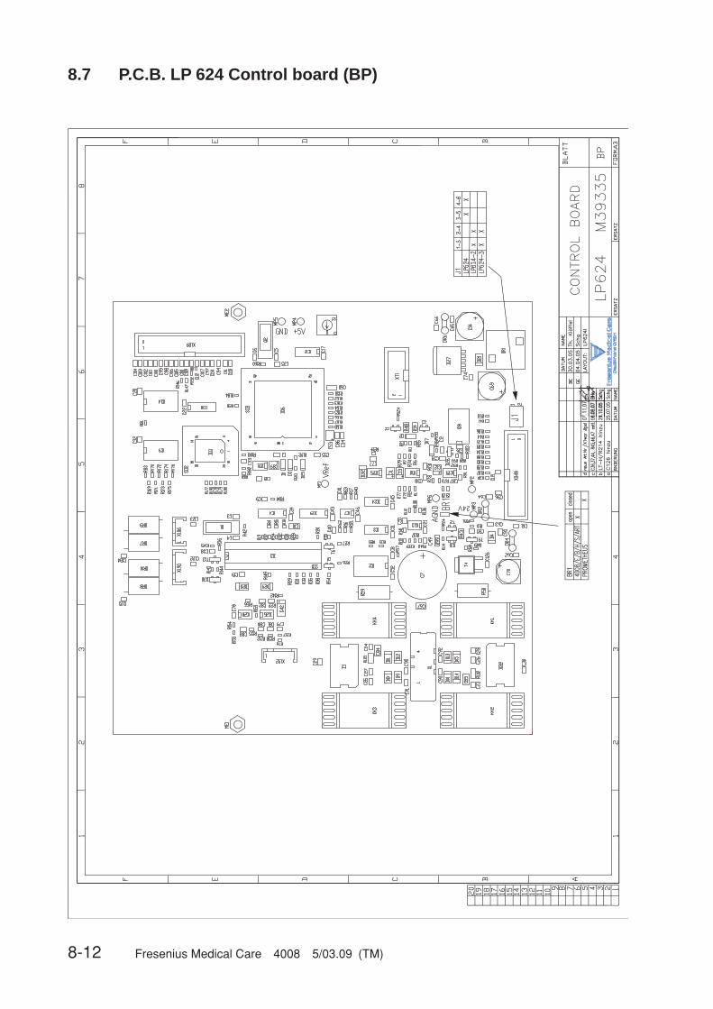
8-12 Fresenius Medical Care 4008 5/03.09 (TM)
8.7 P.C.B. LP 624 Control board (BP)
07.11
.07
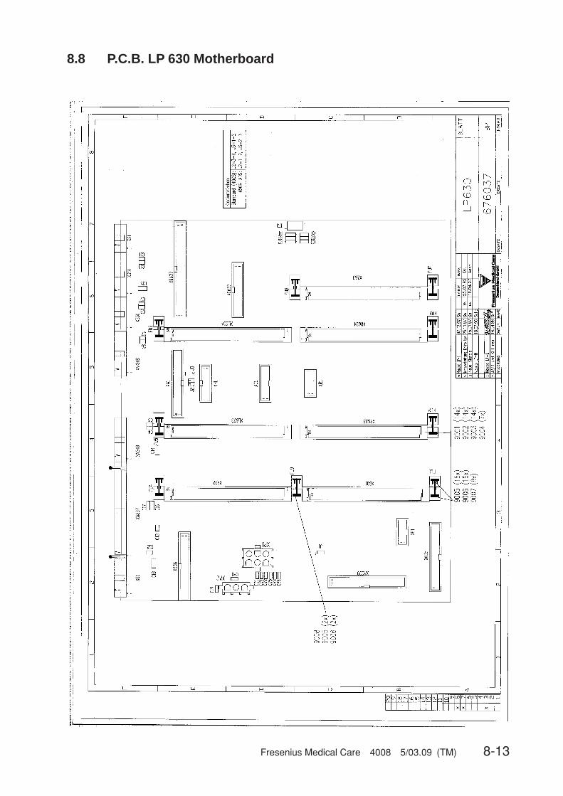
Fresenius Medical Care 4008 5/03.09 (TM) 8-13
8.8 P.C.B. LP 630 Motherboard

8-14 Fresenius Medical Care 4008 5/03.09 (TM)
8.9 P.C.B. LP 631 CPU 1
8018
8M
icro
-co
ntr
olle
r
128
KB
yte
RA
M8
KB
yte
BA
TR
AM
RT
C
ADDRESSES DATA
SIO
2 C
HA
NN
EL
512
KB
yte
EP
RO
M
DIP
-SW
1D
IP-S
W2
LE
D's
PAL
WA
TC
HD
OG
Ad
dre
ss b
us
Co
ntr
ol b
us
Dat
a b
us
Fig.: Block diagram P.C.B. LP 631 CPU 1

Fresenius Medical Care 4008 5/03.09 (TM) 8-15
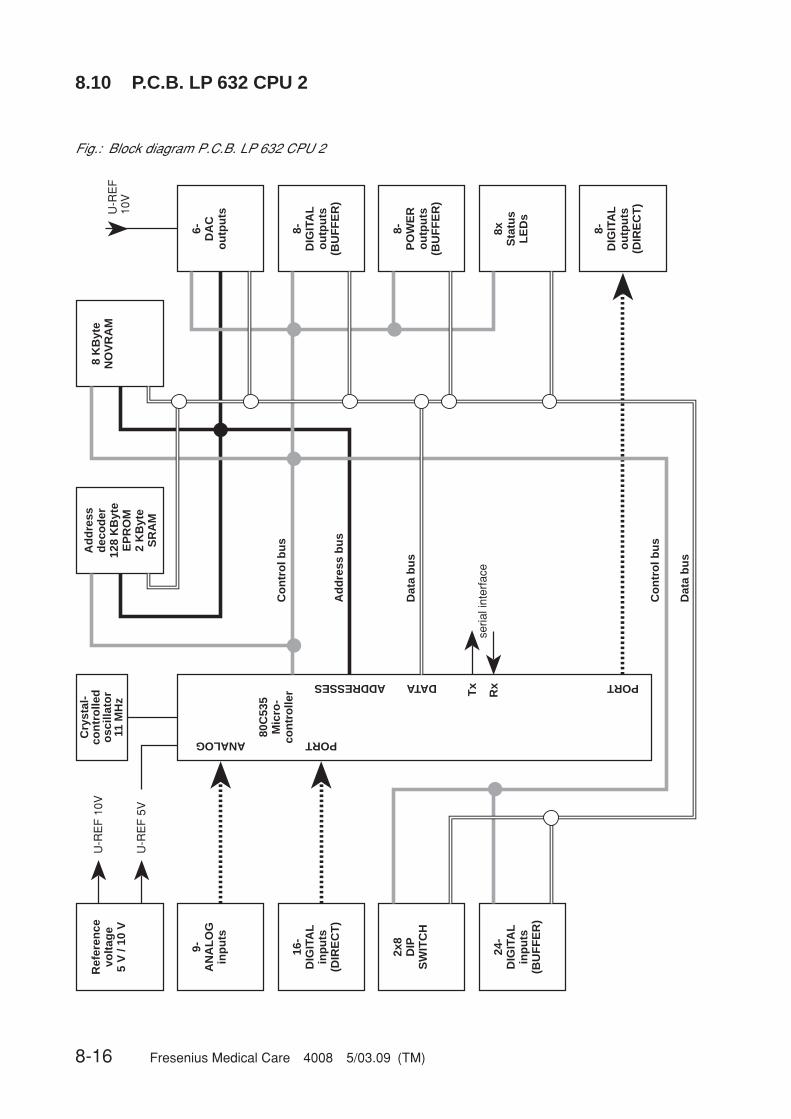
8-16 Fresenius Medical Care 4008 5/03.09 (TM)
8.10 P.C.B. LP 632 CPU 2
Fig.: Block diagram P.C.B. LP 632 CPU 2
Ref
eren
cevo
ltag
e5
V /
10 V
9-A
NA
LO
Gin
pu
ts
16-
DIG
ITA
Lin
pu
ts(D
IRE
CT
)
2x8
DIP
SW
ITC
H
24-
DIG
ITA
Lin
pu
ts(B
UF
FE
R)
U-R
EF
10V
U-R
EF
5V
Cry
stal
-co
ntr
olle
do
scill
ato
r 11
MH
z
80C
535
Mic
ro-
con
tro
ller
Ad
dre
ssd
eco
der
128
KB
yte
EP
RO
M2
KB
yte
SR
AM
8 K
Byt
eN
OV
RA
M
6-D
AC
ou
tpu
ts
8-D
IGIT
AL
ou
tpu
ts(B
UF
FE
R)
8xS
tatu
sL
ED
s
8-D
IGIT
AL
ou
tpu
ts(D
IRE
CT
)
ANALOG PORT
ADDRESSES DATA PORT
Tx
Rx
seria
l int
erfa
ce
U-R
EF
10V
8-P
OW
ER
ou
tpu
ts(B
UF
FE
R)
Ad
dre
ss b
us
Co
ntr
ol b
us
Co
ntr
ol b
us
Dat
a b
us
Dat
a b
us

Fresenius Medical Care 4008 5/03.09 (TM) 8-17
20.08.07
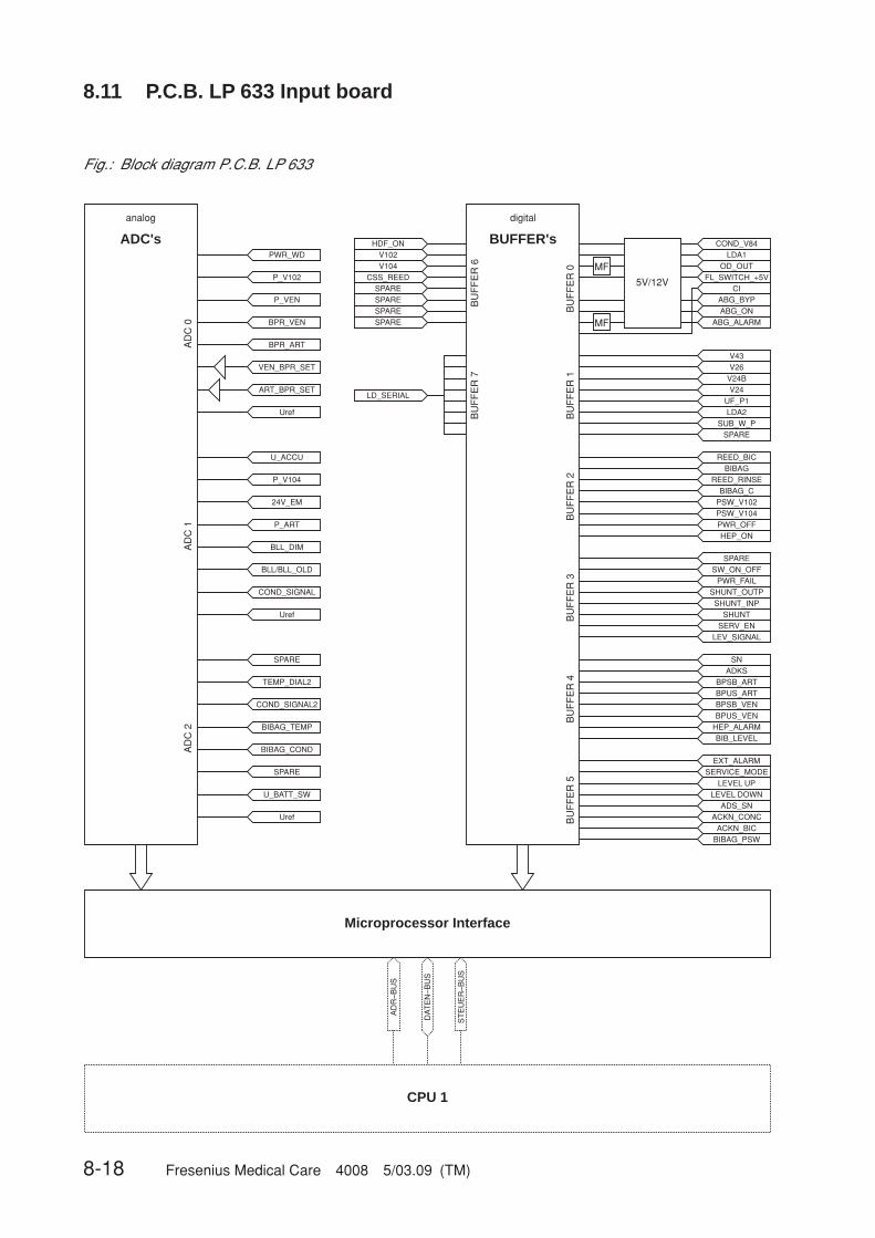
8-18 Fresenius Medical Care 4008 5/03.09 (TM)
8.11 P.C.B. LP 633 Input board
HDF_ON COND_V84LDA1
OD_OUTFL_SWITCH_+5V
CIABG_BYPABG_ON
ABG_ALARM
V43V26
V24B
UF_P1LDA2
SUB_W_PSPARE
REED_BICBIBAG
REED_RINSEBIBAG_C
PSW_V102PSW_V104PWR_OFFHEP_ON
SPARESW_ON_OFF
PWR_FAILSHUNT_OUTPSHUNT_INP
SHUNTSERV_EN
LEV_SIGNAL
SNADKS
BPSB_ARTBPUS_ARTBPSB_VENBPUS_VEN
HEP_ALARMBIB_LEVEL
EXT_ALARMSERVICE_MODE
LEVEL UPLEVEL DOWN
ADS_SNACKN_CONC
ACKN_BICBIBAG_PSW
V24
5V/12V
MF
BU
FF
ER
0B
UF
FE
R 1
BU
FF
ER
2B
UF
FE
R 3
BU
FF
ER
4B
UF
FE
R 5
V102V104
CSS_REEDSPARESPARESPARESPARE
BU
FF
ER
6B
UF
FE
R 7
LD_SERIAL
digital
BUFFER's
AD
C 0
analog
ADC'sPWR_WD
P_V102
P_VEN
BPR_VEN
BPR_ART
VEN_BPR_SET
ART_BPR_SET
Uref
U_ACCU
P_V104
24V_EM
P_ART
BLL_DIM
BLL/BLL_OLD
COND_SIGNAL
Uref
SPARE
U_BATT_SW
Uref
TEMP_DIAL2
COND_SIGNAL2
BIBAG_TEMP
BIBAG_COND
SPARE
AD
C 1
AD
C 2
Microprocessor Interface
MF
ST
EU
ER
–BU
S
AD
R–B
US
DA
TE
N–B
US
CPU 1
Fig.: Block diagram P.C.B. LP 633

Fresenius Medical Care 4008 5/03.09 (TM) 8-19
27.0
7.07
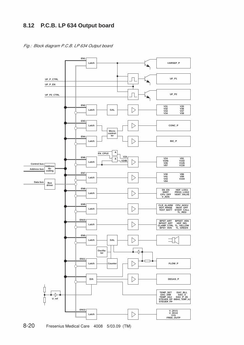
8-20 Fresenius Medical Care 4008 5/03.09 (TM)
8.12 P.C.B. LP 634 Output board
Fig.: Block diagram P.C.B. LP 634 Output board
+AIRSEP_P
UF_P1
UF_P2
V31V32V33V34
CONC_P
BIC_P
V24V24bV26V87
V30V41V43V84
CLR_ALARMHOT_RINSETEST_BATT
BPST_ARTBPSST_ART
CLAMP_CTRLBPST_VEN
FLOW_P
DEGAS_PD/A
U_ref
Latch Counter
Latch GAL
Oscilla-tor
Latch
Latch
Latch
Latch
Latch
Latch
Latch
Latch
&
&V24
V24B
EN_CPU2
Micro-control-
ler
GAL
Latch
EN1
EN2
EN3
EN4
EN6
EN7
EN8
EN9
EN10
EN5
EN11
EN12
CPU_AKKUHEAT_OFF
STAFF_CALLTL_RED
V35V36V37V38
V91V102V126V130
V86V99V104
BPSST_VENHDF_SEL
TL_YELLOWTL_GREEN
UF_P_CTRL
UF_P_EN
UF_P2_CTRL
SN_ENSNST
CPU_OFFV_ADS
HDF_LOG1PROG_LOG2VENT_VALVE
V_ZKV1V_ZKV2
VY5FREE_OUTP
Latch
TEMP_SETDAC_DIM
TEMP_ADJSTEUER_EPSTEUER_FP
DAC_BLLDAC_X
DAC_P_ZEBIBAG_TEMP_AJ
Addressde-
codingAddress bus
Control bus
Busdriver
Data bus
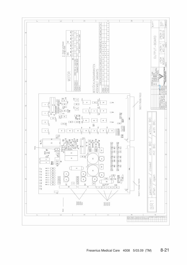
Fresenius Medical Care 4008 5/03.09 (TM) 8-21
21.1
1.06

8-22 Fresenius Medical Care 4008 5/03.09 (TM)
8.13 P.C.B. LP 635 Display board
Fig.: Block diagram P.C.B. LP 635 Display board
BargraphArtVenTMP
Conductivity
Chip-SelectDecoding
CSWRRDA0A1A2A3A4
AlphaDisplay
BrightnessControl
KeyboardEncoding
BargraphTemperature
Flow
Alarm LEDKey click
Status LED'sTraffic Light
UF GoalUF TimeUF Rate
UF Volume
Key interrupt
Key matrix (Plug X2)
CS 1 – 12
Data bus D0 – D7
Duty
CS 16, 17
CS 18
CS 19
CS 20
CS 21
CS 22
CS 23
Cycle

Fresenius Medical Care 4008 5/03.09 (TM) 8-23
8-24 Fresenius Medical Care 4008 5/03.09 (TM)
8.14 P.C.B. LP 636 External connectors
Fresenius Medical Care 4008 5/03.09 (TM) 8-25
8.15 P.C.B. LP 950 Control board (HEP)
19.10
.06
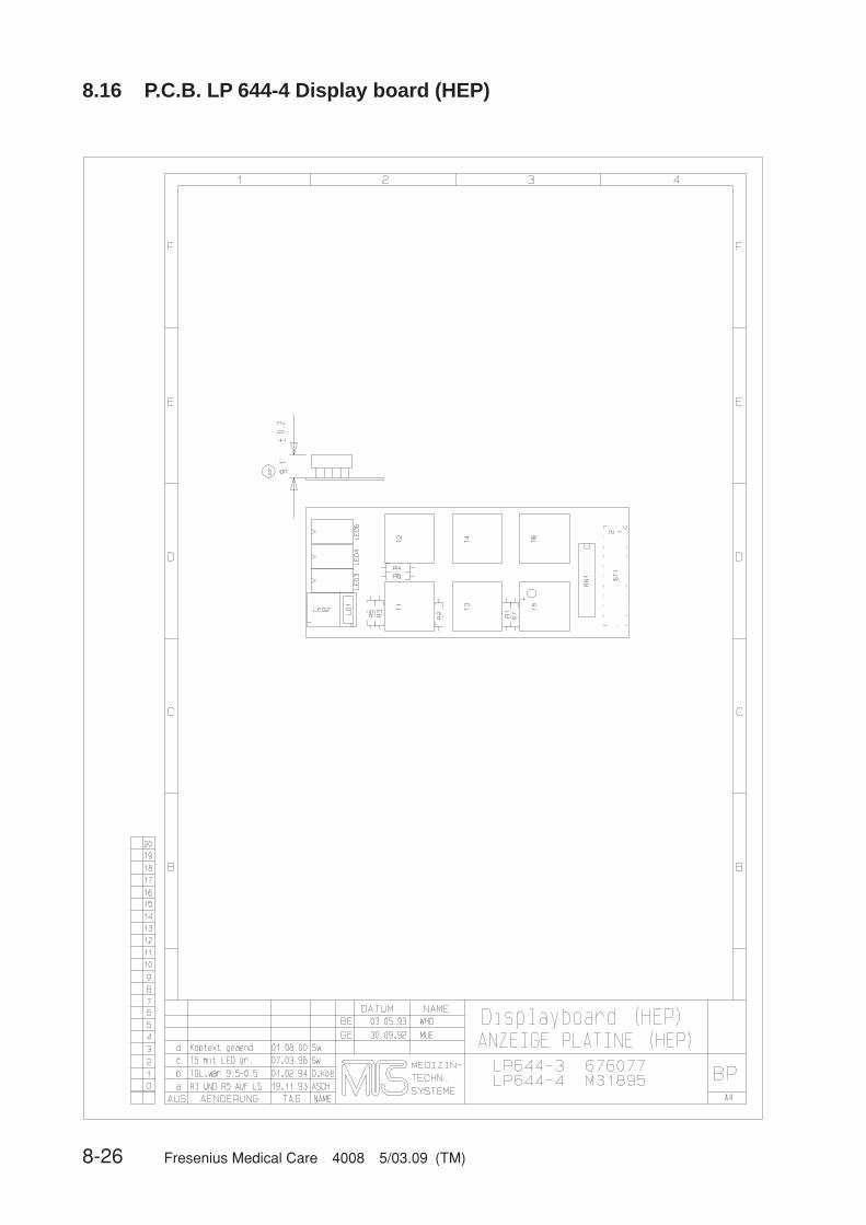
8-26 Fresenius Medical Care 4008 5/03.09 (TM)
8.16 P.C.B. LP 644-4 Display board (HEP)
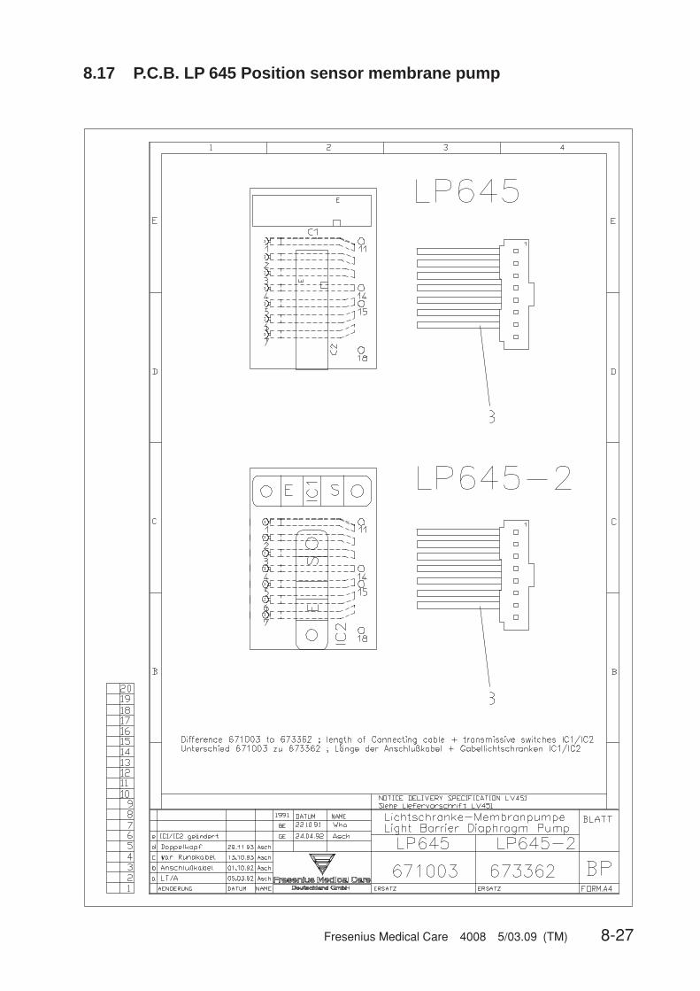
Fresenius Medical Care 4008 5/03.09 (TM) 8-27
8.17 P.C.B. LP 645 Position sensor membrane pump
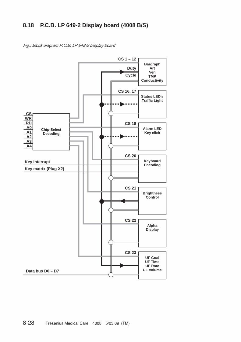
8-28 Fresenius Medical Care 4008 5/03.09 (TM)
8.18 P.C.B. LP 649-2 Display board (4008 B/S)
Fig.: Block diagram P.C.B. LP 649-2 Display board
BargraphArtVenTMP
Conductivity
Chip-SelectDecoding
CSWRRDA0A1A2A3A4
AlphaDisplay
BrightnessControl
KeyboardEncoding
Alarm LEDKey click
Status LED'sTraffic Light
UF GoalUF TimeUF Rate
UF Volume
Key interrupt
Key matrix (Plug X2)
CS 1 – 12
Data bus D0 – D7
Duty
CS 16, 17
CS 18
CS 20
CS 21
CS 22
CS 23
Cycle

Fresenius Medical Care 4008 5/03.09 (TM) 8-29
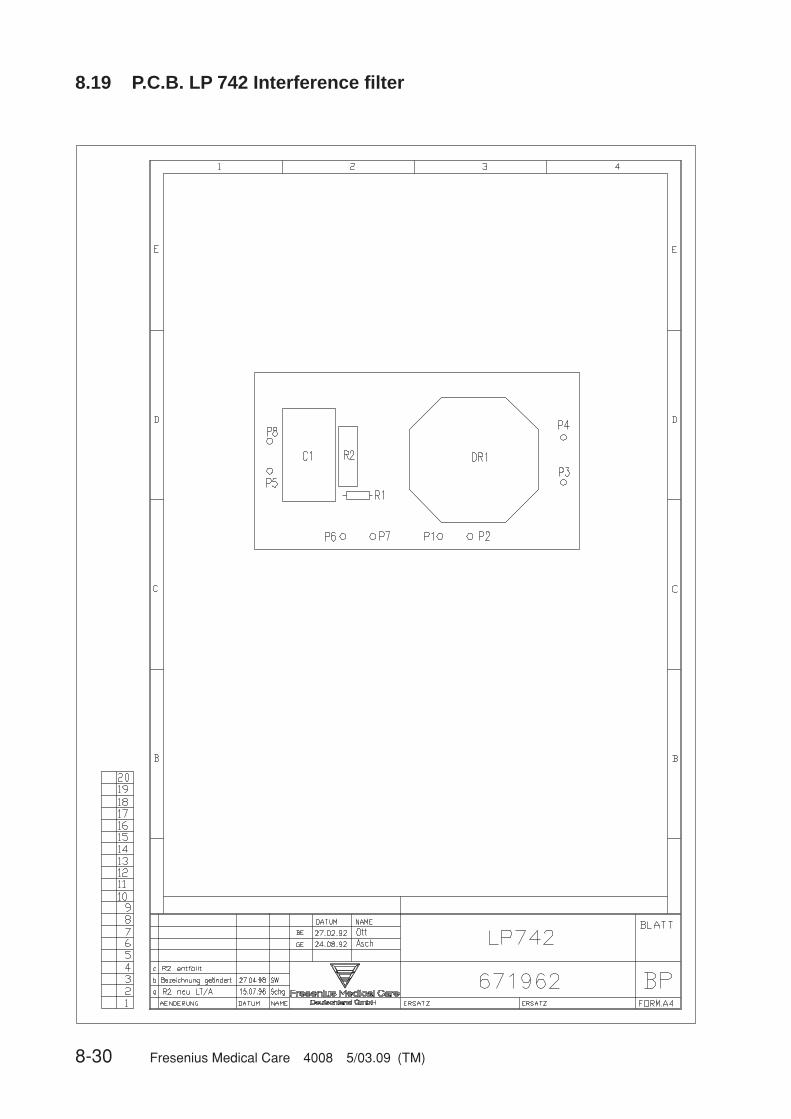
8-30 Fresenius Medical Care 4008 5/03.09 (TM)
8.19 P.C.B. LP 742 Interference filter

Fresenius Medical Care 4008 5/03.09 (TM) 8-31
8.20 P.C.B. LP 748 Display board (BP)

8-32 Fresenius Medical Care 4008 5/03.09 (TM)
8.21 P.C.B. LP 763 Multi interface board (COMMCO III)
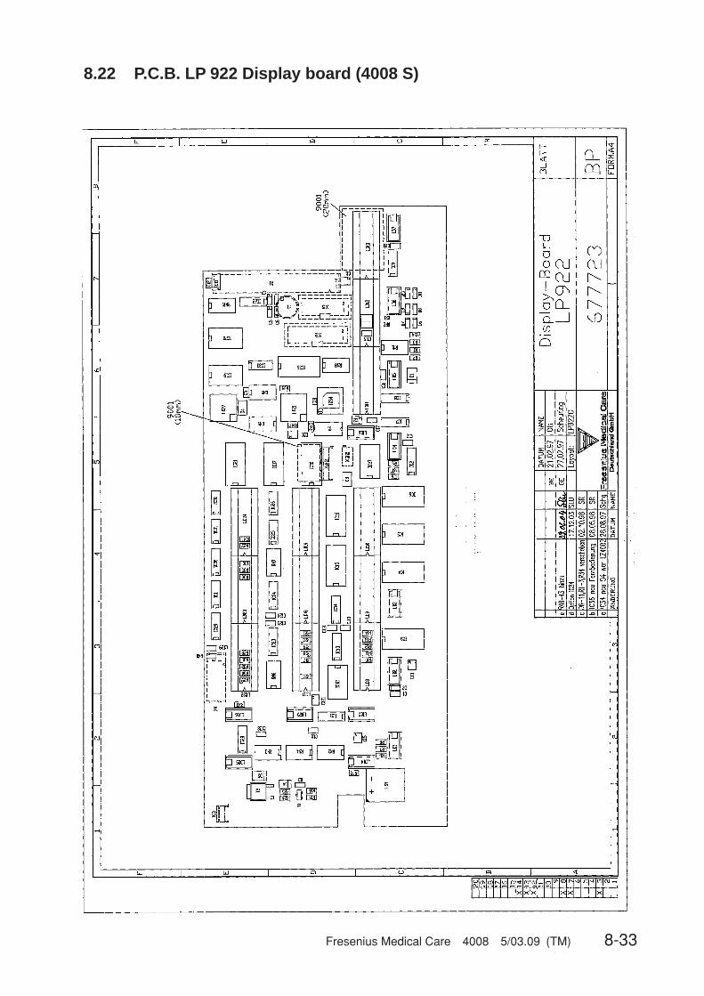
Fresenius Medical Care 4008 5/03.09 (TM) 8-33
8.22 P.C.B. LP 922 Display board (4008 S)

8-34 Fresenius Medical Care 4008 5/03.09 (TM)
8.23 P.C.B. LP 923 Traffic light (4008 H/S)

Fresenius Medical Care 4008 5/03.09 (TM) 8-35
8.24 P.C.B. LP 924 Display board (4008 H)
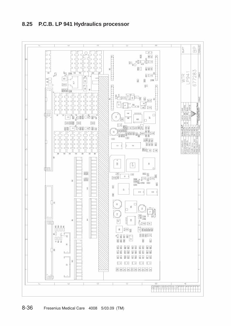
8-36 Fresenius Medical Care 4008 5/03.09 (TM)
8.25 P.C.B. LP 941 Hydraulics processor
12.Nov.07

Fresenius Medical Care 4008 5/03.09 (TM) 8-37
8.26 Heater board (power supply unit 4008)
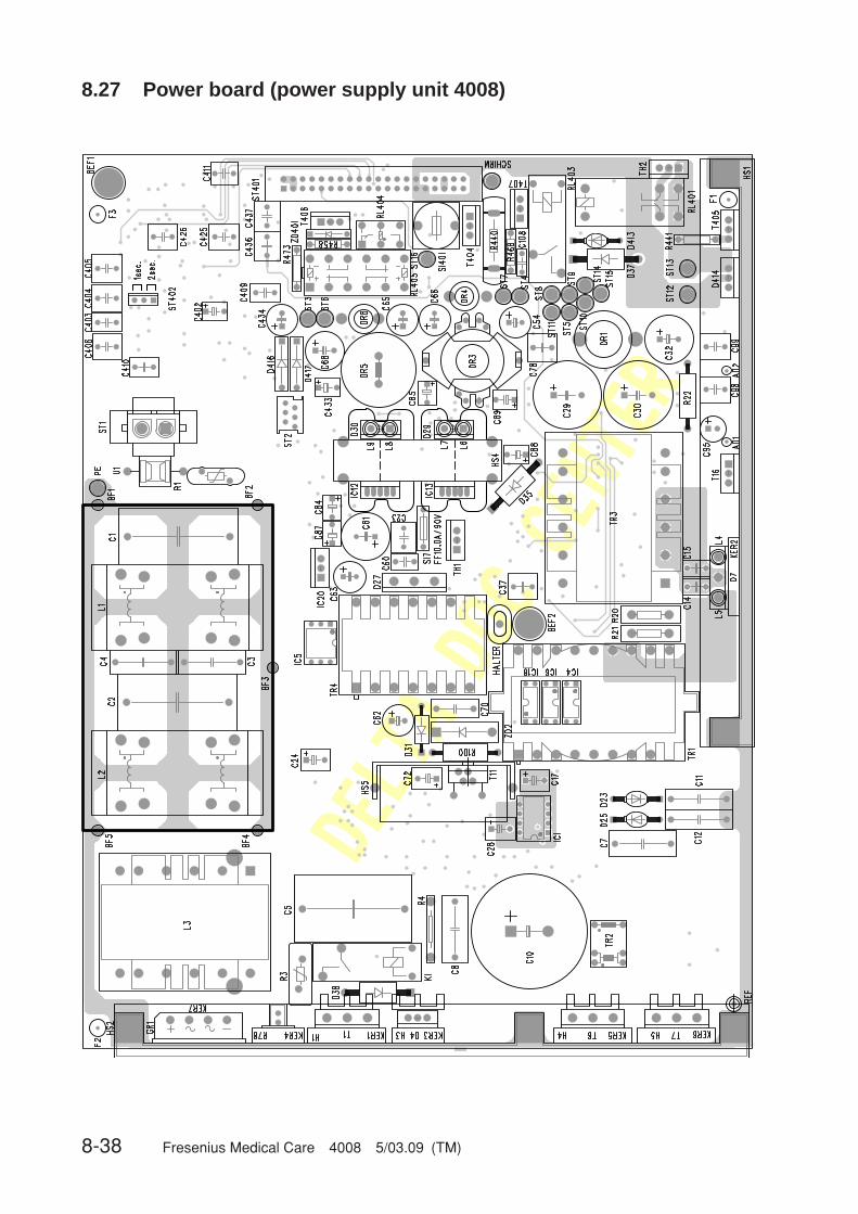
8-38 Fresenius Medical Care 4008 5/03.09 (TM)
8.27 Power board (power supply unit 4008)