Embed Size (px)
Citation preview
128-7192A1 of 20
4 Channel Remote Start / Keyless Entry SystemInstallation Instructions
This Unit Is Intended For Installation In Vehicles With12 Volt Negative Ground Electrical Systems,
Gasoline or Diesel With True Tach Reference And Automatic Transmissions Only.
Kit Contents Control Module(2) - 4 Button Code Hopping Transmitters4 Channel Code Learning ReceiverExternal Superheterodyne Antenna/Receiver(1) - Multi Pin Input/Output Harness(1) - Six Pin Power Harness(1) - Four Pin Auxiliary Harness(1) - Two Pin I/O Harness(1) - Accessory 2 Pin Connector(1) - 2 Pin Door Lock Harness(2) - 30 Amp In-line Fuse Holders With Fuses(1) - Control Switch(1) - Programming Switch(1) - Ring Terminal(4) - 1/2" Long Screws(1) - Pin Switch(1) - Remote Start Warning Label(1) - Literature Package
Model PRO-9275TInstallation Manual
Released: 6-28-04Rev "a" To Indicate Fuses on Ignition Harenss 7/06
128-7192A2 of 20
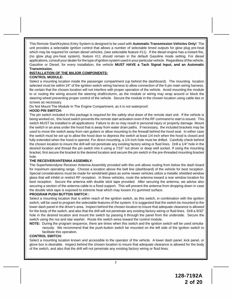
This Remote Start/Keyless Entry System is designed to be used with Automatic Transmission Vehicles Only! Theunit provides a selectable ignition control that allows a number of selectable timed outputs for glow plug pre-heatwhich may be required for certain diesel vehicles, (see selectable feature #11). If the diesel engine has a instant fire,(no glow plug pre-heat system), feature #11 should remain in the default Gasoline mode setting. For dieselapplications, consult your dealer for the type of ignition system used in your particular vehicle. Regardless of the vehicle,Gasoline or Diesel, for every installation, the vehicle MUST HAVE a Tach Signal Input, and an AutomaticTransmission.INSTALLATION OF THE MAJOR COMPONENTS:CONTROL MODULE:Select a mounting location inside the passenger compartment (up behind the dashboard). The mounting locationselected must be within 24" of the ignition switch wiring harness to allow connection of the 6 pin main wiring harness.Be certain that the chosen location will not interfere with proper operation of the vehicle. Avoid mounting the moduleto or routing the wiring around the steering shaft/column, as the module or wiring may wrap around or block thesteering wheel preventing proper control of the vehicle. Secure the module in the chosen location using cable ties orscrews as necessary.Do Not Mount The Module In The Engine Compartment, as it is not waterproof.HOOD PIN SWITCH:The pin switch included in this package is required for the safety shut down of the remote start unit. If the vehicle isbeing worked on, this hood switch prevents the remote start activation even if the RF command to start is issued. Thisswitch MUST be installed in all applications Failure to do so may result in personal injury or property damage. Mountthe switch in an area under the hood that is away from water drain paths. If necessary, the included brackets may beused to move the switch away from rain gutters or allow mounting to the firewall behind the hood seal. In either casethe switch must be set up to allow the hood door to depress the switch at least 1/4 inch when the hood is closed andfully extended when the hood is opened. For direct mounting, a 1/4 inch hole must be drilled. Carefully check behindthe chosen location to insure the drill will not penetrate any existing factory wiring or fluid lines. Drill a 1/4" hole in thedesired location and thread the pin switch into it using a 7/16" nut driver or deep well socket. If using the mountingbracket, first secure the bracket to the desired location and secure the pin switch in the pre-threaded mounting brackethole.THE RECEIVER/ANTENNA ASSEMBLY:The Superheterodyne Receiver Antenna Assembly provided with this unit allows routing from below the dash boardfor maximum operating range. Choose a location above the belt line (dashboard) of the vehicle for best reception.Special considerations must be made for windshield glass as some newer vehicles utilize a metallic shielded windowglass that will inhibit or restrict RF reception. In these vehicles, route the antenna toward a rear window location forbest reception. Secure the antenna with double stick tape provided. After securing the antenna, we advise alsosecuring a section of the antenna cable to a fixed support. This will prevent the antenna from dropping down in casethe double stick tape is exposed to extreme heat which may loosen it's gummed surface.PROGRAM PUSH BUTTON SWITCH :Select a mounting location that is within reach of the ignition switch, as this switch, in combination with the ignitionswitch, will be used to program the selectable features of the system. It is suggested that the switch be mounted to thelower dash panel in the driver's area. Inspect behind the chosen location to insure that adequate clearance is allowedfor the body of the switch, and also that the drill will not penetrate any existing factory wiring or fluid lines. Drill a 9/32"hole in the desired location and mount the switch by passing it through the panel from the underside. Secure theswitch using the nut and star washer. Route the switch wires toward the control module.NOTE: During the program sequence, there are times when this switch and the ignition switch will be used simulta-
neously. We recommend that the push-button switch be mounted on the left side of the ignition switch tofacilitate this operation.
CONTROL SWITCH:Select a mounting location known and accessible to the operator of the vehicle. A lower dash panel, kick panel, orglove box is desirable. Inspect behind the chosen location to insure that adequate clearance is allowed for the bodyof the switch, and also that the drill will not penetrate any existing factory wiring or fluid lines.
2
128-7192A3 of 20
Drill a 1/4" hole in the desired location and mount the switch by passing it through the panel from theunderside. Secure the switch using the nut, star washer, and on/off face plate. It is suggested that theswitch be oriented to allow the on position to be up toward the driver and the off position to be down or awayfrom the driver. Route the switch wires toward the control module.
The APS-685 is to be used in vehicles with AUTOMATIC TRANSMISSIONS only! Although this combina-tion Keyless Entry/Remote Start unit is a sophisticated system with many advanced features, IT MUSTNOT be installed into a vehicle with a manually operated transmission. Doing so may result in seriouspersonal injury and property damage.
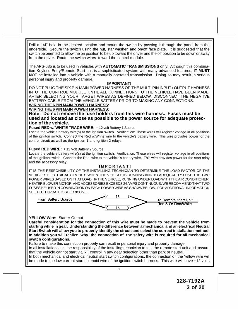
IMPORTANT!DO NOT PLUG THE SIX PIN MAIN POWER HARNESS OR THE MULTI PIN INPUT / OUTPUT HARNESSINTO THE CONTROL MODULE UNTIL ALL CONNECTIONS TO THE VEHICLE HAVE BEEN MADE.AFTER SELECTING YOUR TARGET WIRES AS DEFINED BELOW, DISCONNECT THE NEGATIVEBATTERY CABLE FROM THE VEHICLE BATTERY PRIOR TO MAKING ANY CONNECTIONS.WIRING THE 6 PIN MAIN POWER HARNESS:WIRING THE 6 PIN MAIN POWER HARNESS:Note: Do not remove the fuse holders from this wire harness. Fuses must beused and located as close as possible to the power source for adequate protec-tion of the vehicle.Fused RED w/ WHITE TRACE WIRE: + 12 volt Battery 1 SourceLocate the vehicle battery wire(s) at the ignition switch. Verification: These wires will register voltage in all positionsof the igniiton switch. Connect the Red w/White wire to the vehicle's battery wire. This wire provides power for thecontrol circuit as well as the ignition 1 and ignition 2 relays.
Fused RED WIRE: + 12 Volt Battery 2 SourceLocate the vehicle battery wire(s) at the ignition switch. Verification: These wires will register voltage in all positionsof the igniiton switch. Connect the Red wire to the vehicle's battery wire. This wire provides power for the start relayand the accessory relay.
I M P O R T A N T !IT IS THE RESPONSIBILITY OF THE INSTALLING TECHNICIAN TO DETERMINE THE LOAD FACTOR OF THEVEHICLES ELECTRICAL CIRCUITS WHEN THE VEHICLE IS RUNNING AND TO ADEQUATELY FUSE THE TWOPOWER WIRES BASED ON THAT LOAD. IF THE VEHICLE, RUNNING UNDER LOAD WITH THE AIR CONDITIONER,HEATER BLOWER MOTOR, AND ACCESSORIES EXCEEDS 24 AMPS CONTINUOUS, WE RECOMMEND THAT TWOFUSES BE USED IN COMBINATION ON EACH POWER WIRE AS SHOWN BELOW. FOR ADDITIONAL INFORMATIONSEE TECH UPDATE ISSUED 9/30/96.
YELLOW Wire: Starter OutputCareful consideration for the connection of this wire must be made to prevent the vehicle fromstarting while in gear. Understanding the difference between a mechanical and an electrical NeutralStart Switch will allow you to properly identify the circuit and select the correct installation method.In addition you will realize why the connection of the safety wire is required for all mechanicalswitch configurations.Failure to make this connection properly can result in personal injury and property damage.In all installations it is the responsibility of the installing technician to test the remote start unit and assurethat the vehicle cannot start via RF control in any gear selection other than park or neutral.In both mechanical and electrical neutral start switch configurations, the connection of the Yellow wire willbe made to the low current start solenoid wire of the ignition switch harness. This wire will have +12 volts
3
128-7192A4 of 20
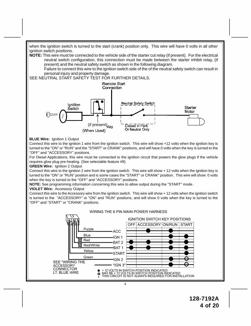
when the ignition switch is turned to the start (crank) position only. This wire will have 0 volts in all otherignition switch positions.NOTE: This wire must be connected to the vehicle side of the starter cut relay (if present). For the electrical
neutral switch configuration, this connection must be made between the starter inhibit relay, (ifpresent) and the neutral safety switch as shown in the following diagram.Failure to connect this wire to the ignition switch side of the of the neutral safety switch can result inpersonal injury and property damage.
SEE NEUTRAL START SAFETY TEST FOR FURTHER DETAILS.
BLUE Wire: Ignition 1 OutputConnect this wire to the ignition 1 wire from the ignition switch. This wire will show +12 volts when the ignition key isturned to the "ON" or "RUN" and the "START" or CRANK" positions, and will have 0 volts when the key is turned to the"OFF" and "ACCESSORY" positions.For Diesel Applications, this wire must be connected to the ignition circuit that powers the glow plugs if the vehiclerequires glow plug pre-heating. (See selectable feature #9)GREEN Wire: Ignition 2 OutputConnect this wire to the ignition 2 wire from the ignition switch. This wire will show + 12 volts when the ignition key isturned to the "ON" or "RUN" position and is some cases the "START" or CRANK" position. This wire will show 0 voltswhen the key is turned to the "OFF" and "ACCESSORY" positions.NOTE: See programming information concerning this wire to allow output during the "START" mode.VIOLET Wire: Accessory OutputConnect this wire to the Accessory wire from the ignition switch. This wire will show + 12 volts when the ignition switchis turned to the "ACCESSORY" or "ON" and "RUN" positions, and will show 0 volts when the key is turned to the"OFF" and "START" or "CRANK" positions.
4
(if present)
128-7192A5 of 20
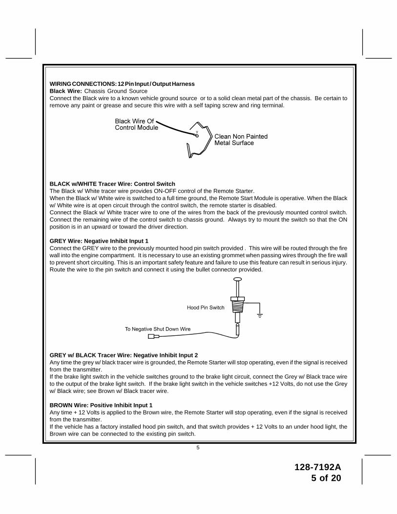
WIRING CONNECTIONS: 12 Pin Input / Output HarnessBlack Wire: Chassis Ground SourceConnect the Black wire to a known vehicle ground source or to a solid clean metal part of the chassis. Be certain toremove any paint or grease and secure this wire with a self taping screw and ring terminal.
BLACK w/WHITE Tracer Wire: Control SwitchThe Black w/ White tracer wire provides ON-OFF control of the Remote Starter.When the Black w/ White wire is switched to a full time ground, the Remote Start Module is operative. When the Blackw/ White wire is at open circuit through the control switch, the remote starter is disabled.Connect the Black w/ White tracer wire to one of the wires from the back of the previously mounted control switch.Connect the remaining wire of the control switch to chassis ground. Always try to mount the switch so that the ONposition is in an upward or toward the driver direction.
GREY Wire: Negative Inhibit Input 1Connect the GREY wire to the previously mounted hood pin switch provided . This wire will be routed through the firewall into the engine compartment. It is necessary to use an existing grommet when passing wires through the fire wallto prevent short circuiting. This is an important safety feature and failure to use this feature can result in serious injury.Route the wire to the pin switch and connect it using the bullet connector provided.
GREY w/ BLACK Tracer Wire: Negative Inhibit Input 2Any time the grey w/ black tracer wire is grounded, the Remote Starter will stop operating, even if the signal is receivedfrom the transmitter.If the brake light switch in the vehicle switches ground to the brake light circuit, connect the Grey w/ Black trace wireto the output of the brake light switch. If the brake light switch in the vehicle switches +12 Volts, do not use the Greyw/ Black wire; see Brown w/ Black tracer wire.
BROWN Wire: Positive Inhibit Input 1Any time + 12 Volts is applied to the Brown wire, the Remote Starter will stop operating, even if the signal is receivedfrom the transmitter.If the vehicle has a factory installed hood pin switch, and that switch provides + 12 Volts to an under hood light, theBrown wire can be connected to the existing pin switch.
5
128-7192A6 of 20
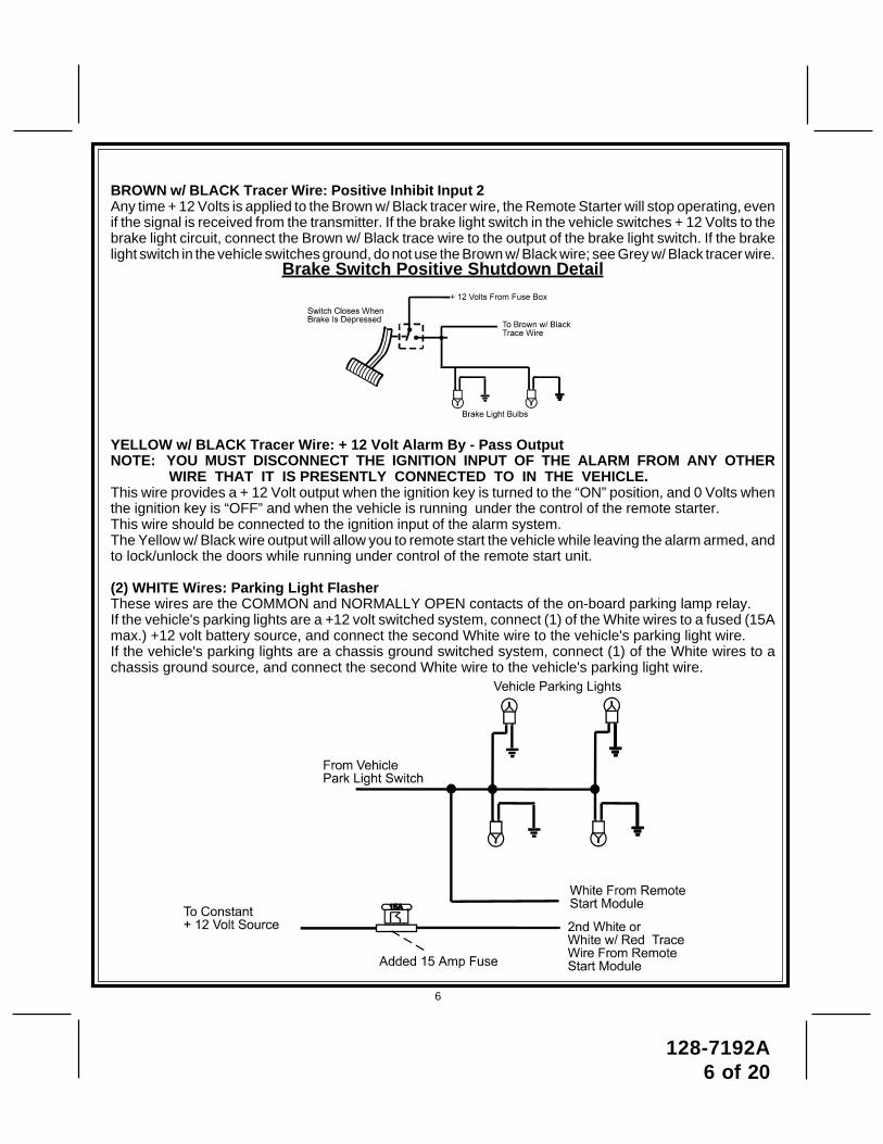
BROWN w/ BLACK Tracer Wire: Positive Inhibit Input 2Any time + 12 Volts is applied to the Brown w/ Black tracer wire, the Remote Starter will stop operating, evenif the signal is received from the transmitter. If the brake light switch in the vehicle switches + 12 Volts to thebrake light circuit, connect the Brown w/ Black trace wire to the output of the brake light switch. If the brakelight switch in the vehicle switches ground, do not use the Brown w/ Black wire; see Grey w/ Black tracer wire.
Brake Switch Positive Shutdown Detail
YELLOW w/ BLACK Tracer Wire: + 12 Volt Alarm By - Pass OutputNOTE: YOU MUST DISCONNECT THE IGNITION INPUT OF THE ALARM FROM ANY OTHER
WIRE THAT IT IS PRESENTLY CONNECTED TO IN THE VEHICLE.This wire provides a + 12 Volt output when the ignition key is turned to the “ON” position, and 0 Volts whenthe ignition key is “OFF” and when the vehicle is running under the control of the remote starter.This wire should be connected to the ignition input of the alarm system.The Yellow w/ Black wire output will allow you to remote start the vehicle while leaving the alarm armed, andto lock/unlock the doors while running under control of the remote start unit.
(2) WHITE Wires: Parking Light FlasherThese wires are the COMMON and NORMALLY OPEN contacts of the on-board parking lamp relay.If the vehicle's parking lights are a +12 volt switched system, connect (1) of the White wires to a fused (15Amax.) +12 volt battery source, and connect the second White wire to the vehicle's parking light wire.If the vehicle's parking lights are a chassis ground switched system, connect (1) of the White wires to achassis ground source, and connect the second White wire to the vehicle's parking light wire.
6

128-7192A7 of 20
GREEN/YELLOW Wire: Diesel Wait To StartFor Diesel glow plug preheat circuits, this wait to start input will allow the ignition to keep the glow plugsactive for the vehicles automatic time out period before cranking the starter motor. If this wire is connectedto the glow plug wire, this will take precedence over the timing setting and the gas/Diesel selection in thefeature selection chart. Use this wire if you do not want to set the timing of the glow plug preheat circuit asshown in the feature selection chart.
LIGHT BLUE Wire: Ignition 3 / Shock Disable OutputThis wire provides a 300mA ground output that becomes active 3 seconds before the Remote Start Unitinitializes, and remains grounded while running plus an additional 4 seconds after the Remote Start Unitturns off. In all of the applications described below, a relay will be required.The Light Blue wire can be used to accommodate the following situations:
A. Shock Sensor By Pass:If there is Shock Sensor used with an alarm system and it is not shunted during the Remote Startactivation period, then vibration from the running vehicle can cause the alarm to trigger. In this case,connect the Light Blue Wire to terminal #86 of a external relay. Connect terminal# 85 of the relay to afused + 12 volt battery source. Cut the shock sensor trigger wire and connect one end of the cut wireto terminal #30 and the other end of the cut wire to terminal #87a. Just before the Remote Start unitis activated, the relay contacts will open, preventing the shock sensor's operation until the RemoteStart unit shuts off.
B. Ignition 3 Output:Some newer vehicles use a third ignition wire which is required to start and keep the vehicle's enginerunning. If this is the case, connect the Light Blue wire to terminal #86 of an external relay. Connectterminal # 30 & # 85 to a fused + 12 volt battery source rated for a minimum of 25 Amp. Connectterminal # 87 to the third ignition wire in the vehicle.
C. GM VATS Key Override:If the vehicle has the General Motors VATS system installed, you will need to by-pass the systemwhile the vehicle is operating under the control of the Remote Start Unit. To Do This;1. Measure the resistance of the resistor pellet on the ignition key then select a resistor within 5% of
the key's value from the resistor pack supplied.2. Locate the pair of VATS wires in the vehicle, usually a pair of thin gauge wires running from the ignition
switch to the VATS control module.
7
128-7192A8 of 20
NOTE: These wires are typically White w/ Black trace and Violet w/ Yellow trace, however in later modelCadillacs, they are run through an orange sleeve, and are either both Black, both Yellow, or bothWhite wires. Consult the factory service manual for additional information.
3. Connect the Light Blue Wire from the Remote Start Unit to terminal #86 of an external relay. Connectterminal #85 of the relay to a fused + 12 volt battery source.
4. Cut (#1) wire (as shown), and connect the ignition switch side of the cut wire to terminal #87a of therelay. Connect the other side of the (#1) wire to terminal #30.
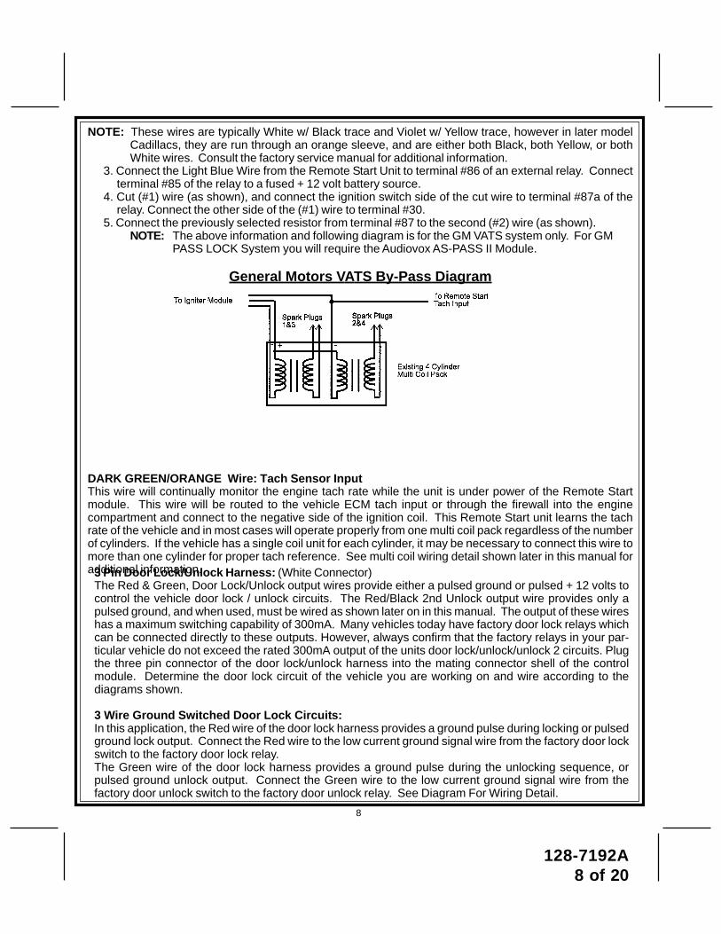
5. Connect the previously selected resistor from terminal #87 to the second (#2) wire (as shown).NOTE: The above information and following diagram is for the GM VATS system only. For GM
PASS LOCK System you will require the Audiovox AS-PASS II Module.
General Motors VATS By-Pass Diagram
DARK GREEN/ORANGE Wire: Tach Sensor InputThis wire will continually monitor the engine tach rate while the unit is under power of the Remote Startmodule. This wire will be routed to the vehicle ECM tach input or through the firewall into the enginecompartment and connect to the negative side of the ignition coil. This Remote Start unit learns the tachrate of the vehicle and in most cases will operate properly from one multi coil pack regardless of the numberof cylinders. If the vehicle has a single coil unit for each cylinder, it may be necessary to connect this wire tomore than one cylinder for proper tach reference. See multi coil wiring detail shown later in this manual foradditional information.3 Pin Door Lock/Unlock Harness: (White Connector)
The Red & Green, Door Lock/Unlock output wires provide either a pulsed ground or pulsed + 12 volts tocontrol the vehicle door lock / unlock circuits. The Red/Black 2nd Unlock output wire provides only apulsed ground, and when used, must be wired as shown later on in this manual. The output of these wireshas a maximum switching capability of 300mA. Many vehicles today have factory door lock relays whichcan be connected directly to these outputs. However, always confirm that the factory relays in your par-ticular vehicle do not exceed the rated 300mA output of the units door lock/unlock/unlock 2 circuits. Plugthe three pin connector of the door lock/unlock harness into the mating connector shell of the controlmodule. Determine the door lock circuit of the vehicle you are working on and wire according to thediagrams shown.
3 Wire Ground Switched Door Lock Circuits:In this application, the Red wire of the door lock harness provides a ground pulse during locking or pulsedground lock output. Connect the Red wire to the low current ground signal wire from the factory door lockswitch to the factory door lock relay.The Green wire of the door lock harness provides a ground pulse during the unlocking sequence, orpulsed ground unlock output. Connect the Green wire to the low current ground signal wire from thefactory door unlock switch to the factory door unlock relay. See Diagram For Wiring Detail.
8
128-7192A9 of 20
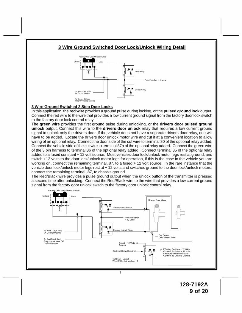
3 Wire Ground Switched 2 Step Door LocksIn this application, the red wire provides a ground pulse during locking, or the pulsed ground lock output.Connect the red wire to the wire that provides a low current ground signal from the factory door lock switchto the factory door lock control relay.The green wire provides the first ground pulse during unlocking, or the drivers door pulsed groundunlock output. Connect this wire to the drivers door unlock relay that requires a low current groundsignal to unlock only the drivers door. If the vehicle does not have a separate drivers door relay, one willhave to be added. Locate the drivers door unlock motor wire and cut it at a convenient location to allowwiring of an optional relay. Connect the door side of the cut wire to terminal 30 of the optional relay added.Connect the vehicle side of the cut wire to terminal 87a of the optional relay added. Connect the green wireof the 3 pin harness to terminal 86 of the optional relay added. Connect terminal 85 of the optional relayadded to a fused constant + 12 volt source. Most vehicles door lock/unlock motor legs rest at ground, andswitch +12 volts to the door lock/unlock motor legs for operation, if this is the case in the vehicle you areworking on, connect the remaining terminal, 87, to a fused + 12 volt source. In the rare instance that thevehicle door lock/unlock motor legs rest at + 12 volts and switches ground to the door lock/unlock motors,connect the remaining terminal, 87, to chassis ground.The Red/Black wire provides a pulse ground output when the unlock button of the transmitter is presseda second time after unlocking. Connect the Red/Black wire to the wire that provides a low current groundsignal from the factory door unlock switch to the factory door unlock control relay.
9
3 Wire Ground Switched Door Lock/Unlock Wiring Detail
128-7192A10 of 20
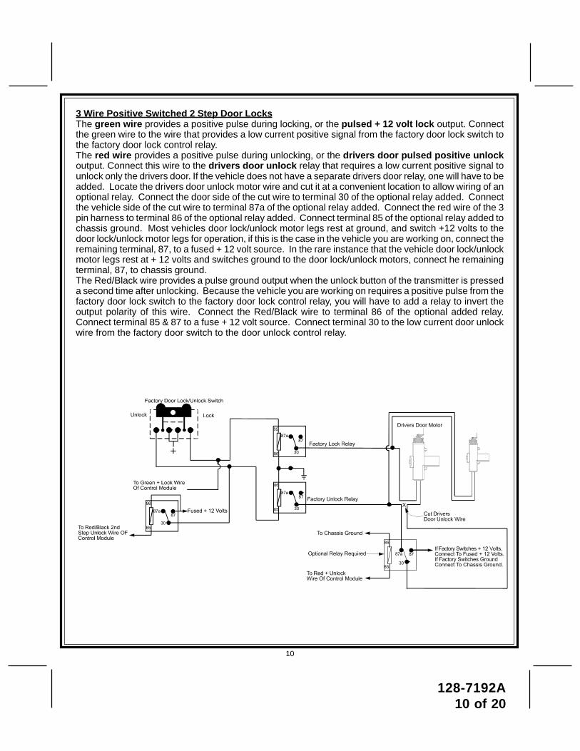
3 Wire Positive Switched 2 Step Door LocksThe green wire provides a positive pulse during locking, or the pulsed + 12 volt lock output. Connectthe green wire to the wire that provides a low current positive signal from the factory door lock switch tothe factory door lock control relay.The red wire provides a positive pulse during unlocking, or the drivers door pulsed positive unlockoutput. Connect this wire to the drivers door unlock relay that requires a low current positive signal tounlock only the drivers door. If the vehicle does not have a separate drivers door relay, one will have to beadded. Locate the drivers door unlock motor wire and cut it at a convenient location to allow wiring of anoptional relay. Connect the door side of the cut wire to terminal 30 of the optional relay added. Connectthe vehicle side of the cut wire to terminal 87a of the optional relay added. Connect the red wire of the 3pin harness to terminal 86 of the optional relay added. Connect terminal 85 of the optional relay added tochassis ground. Most vehicles door lock/unlock motor legs rest at ground, and switch +12 volts to thedoor lock/unlock motor legs for operation, if this is the case in the vehicle you are working on, connect theremaining terminal, 87, to a fused + 12 volt source. In the rare instance that the vehicle door lock/unlockmotor legs rest at + 12 volts and switches ground to the door lock/unlock motors, connect he remainingterminal, 87, to chassis ground.The Red/Black wire provides a pulse ground output when the unlock button of the transmitter is presseda second time after unlocking. Because the vehicle you are working on requires a positive pulse from thefactory door lock switch to the factory door lock control relay, you will have to add a relay to invert theoutput polarity of this wire. Connect the Red/Black wire to terminal 86 of the optional added relay.Connect terminal 85 & 87 to a fuse + 12 volt source. Connect terminal 30 to the low current door unlockwire from the factory door switch to the door unlock control relay.
10
128-7192A11 of 20
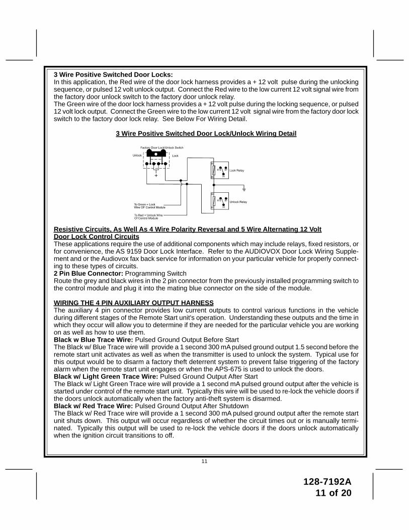
3 Wire Positive Switched Door Locks:In this application, the Red wire of the door lock harness provides a + 12 volt pulse during the unlockingsequence, or pulsed 12 volt unlock output. Connect the Red wire to the low current 12 volt signal wire fromthe factory door unlock switch to the factory door unlock relay.The Green wire of the door lock harness provides a + 12 volt pulse during the locking sequence, or pulsed12 volt lock output. Connect the Green wire to the low current 12 volt signal wire from the factory door lockswitch to the factory door lock relay. See Below For Wiring Detail.
3 Wire Positive Switched Door Lock/Unlock Wiring Detail
Resistive Circuits, As Well As 4 Wire Polarity Reversal and 5 Wire Alternating 12 VoltDoor Lock Control CircuitsThese applications require the use of additional components which may include relays, fixed resistors, orfor convenience, the AS 9159 Door Lock Interface. Refer to the AUDIOVOX Door Lock Wiring Supple-ment and or the Audiovox fax back service for information on your particular vehicle for properly connect-ing to these types of circuits.2 Pin Blue Connector: Programming SwitchRoute the grey and black wires in the 2 pin connector from the previously installed programming switch tothe control module and plug it into the mating blue connector on the side of the module.
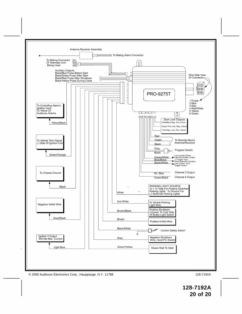
WIRING THE 4 PIN AUXILIARY OUTPUT HARNESSThe auxiliary 4 pin connector provides low current outputs to control various functions in the vehicleduring different stages of the Remote Start unit's operation. Understanding these outputs and the time inwhich they occur will allow you to determine if they are needed for the particular vehicle you are workingon as well as how to use them.Black w Blue Trace Wire: Pulsed Ground Output Before StartThe Black w/ Blue Trace wire will provide a 1 second 300 mA pulsed ground output 1.5 second before theremote start unit activates as well as when the transmitter is used to unlock the system. Typical use forthis output would be to disarm a factory theft deterrent system to prevent false triggering of the factoryalarm when the remote start unit engages or when the APS-675 is used to unlock the doors.Black w/ Light Green Trace Wire: Pulsed Ground Output After StartThe Black w/ Light Green Trace wire will provide a 1 second mA pulsed ground output after the vehicle isstarted under control of the remote start unit. Typically this wire will be used to re-lock the vehicle doors ifthe doors unlock automatically when the factory anti-theft system is disarmed.Black w/ Red Trace Wire: Pulsed Ground Output After ShutdownThe Black w/ Red Trace wire will provide a 1 second 300 mA pulsed ground output after the remote startunit shuts down. This output will occur regardless of whether the circuit times out or is manually termi-nated. Typically this output will be used to re-lock the vehicle doors if the doors unlock automaticallywhen the ignition circuit transitions to off.
11
128-7192A12 of 20
Black w/ Yellow Trace Wire: Ground Output During Start (Crank)The Black w/ Yellow Trace wire will provide a 300 mA ground output while the starter output of the remotestart unit is active. This output can be used to activate the Crank Low/Bulb Test wire found in some GMvehicles. This wire is also referred to as the ECM wake up wire in some Chrysler vehicles.NOTE: The outputs above are low current outputs and must be used with a relay if the circuit's requirement
is more than 300 mA.
Blue and Green w/Black Trace Wires - 2 Pin Accessory Output Harness
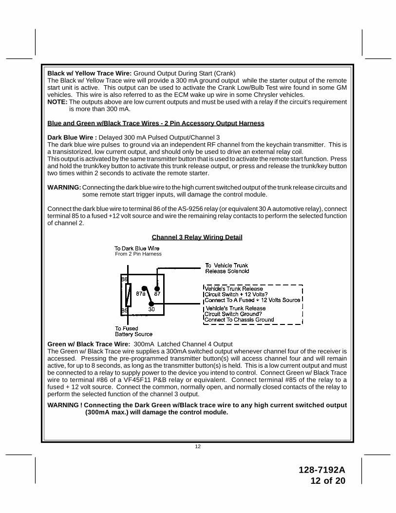
Dark Blue Wire : Delayed 300 mA Pulsed Output/Channel 3The dark blue wire pulses to ground via an independent RF channel from the keychain transmitter. This isa transistorized, low current output, and should only be used to drive an external relay coil.This output is activated by the same transmitter button that is used to activate the remote start function. Pressand hold the trunk/key button to activate this trunk release output, or press and release the trunk/key buttontwo times within 2 seconds to activate the remote starter.
WARNING: Connecting the dark blue wire to the high current switched output of the trunk release circuits andsome remote start trigger inputs, will damage the control module.
Connect the dark blue wire to terminal 86 of the AS-9256 relay (or equivalent 30 A automotive relay), connectterminal 85 to a fused +12 volt source and wire the remaining relay contacts to perform the selected functionof channel 2.
Channel 3 Relay Wiring Detail
Green w/ Black Trace Wire: 300mA Latched Channel 4 OutputThe Green w/ Black Trace wire supplies a 300mA switched output whenever channel four of the receiver isaccessed. Pressing the pre-programmed transmitter button(s) will access channel four and will remainactive, for up to 8 seconds, as long as the transmitter button(s) is held. This is a low current output and mustbe connected to a relay to supply power to the device you intend to control. Connect Green w/ Black Tracewire to terminal #86 of a VF45F11 P&B relay or equivalent. Connect terminal #85 of the relay to afused + 12 volt source. Connect the common, normally open, and normally closed contacts of the relay toperform the selected function of the channel 3 output.
WARNING ! Connecting the Dark Green w/Black trace wire to any high current switched output(300mA max.) will damage the control module.
12
From 2 Pin Harness
128-7192A13 of 20
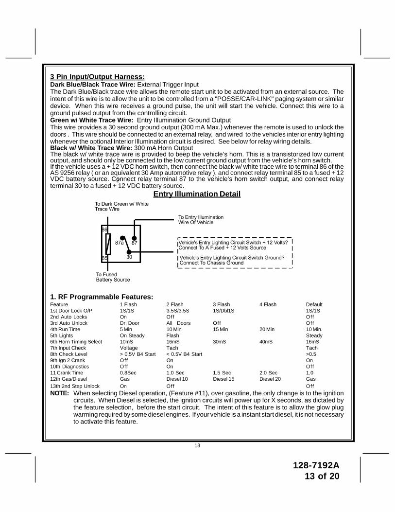
3 Pin Input/Output Harness:Dark Blue/Black Trace Wire: External Trigger InputThe Dark Blue/Black trace wire allows the remote start unit to be activated from an external source. Theintent of this wire is to allow the unit to be controlled from a "POSSE/CAR-LINK" paging system or similardevice. When this wire receives a ground pulse, the unit will start the vehicle. Connect this wire to aground pulsed output from the controlling circuit.Green w/ White Trace Wire: Entry Illumination Ground OutputThis wire provides a 30 second ground output (300 mA Max.) whenever the remote is used to unlock thedoors . This wire should be connected to an external relay, and wired to the vehicles interior entry lightingwhenever the optional Interior Illumination circuit is desired. See below for relay wiring details.Black w/ White Trace Wire: 300 mA Horn OutputThe black w/ white trace wire is provided to beep the vehicle’s horn. This is a transistorized low currentoutput, and should only be connected to the low current ground output from the vehicle’s horn switch.If the vehicle uses a + 12 VDC horn switch, then connect the black w/ white trace wire to terminal 86 of theAS 9256 relay ( or an equivalent 30 Amp automotive relay ), and connect relay terminal 85 to a fused + 12VDC battery source. Connect relay terminal 87 to the vehicle’s horn switch output, and connect relayterminal 30 to a fused + 12 VDC battery source.
Entry Illumination Detail
1. RF Programmable Features:Feature 1 Flash 2 Flash 3 Flash 4 Flash Default1st Door Lock O/P 1S/1S 3.5S/3.5S 1S/Dbl1S 1S/1S2nd Auto Locks On Off Off3rd Auto Unlock Dr. Door All Doors Off Off4th Run Time 5 Min 10 Min 15 Min 20 Min 10 Min.5th Lights On Steady Flash Steady6th Horn Timing Select 10mS 16mS 30mS 40mS 16mS7th Input Check Voltage Tach Tach8th Check Level > 0.5V B4 Start < 0.5V B4 Start >0.59th Ign 2 Crank Off On On10th Diagnostics Off On Off11 Crank Time 0.8Sec 1.0 Sec 1.5 Sec 2.0 Sec 1.012th Gas/Diesel Gas Diesel 10 Diesel 15 Diesel 20 Gas13th 2nd Step Unlock On Off OffNOTE: When selecting Diesel operation, (Feature #11), over gasoline, the only change is to the ignition
circuits. When Diesel is selected, the ignition circuits will power up for X seconds, as dictated bythe feature selection, before the start circuit. The intent of this feature is to allow the glow plugwarming required by some diesel engines. If your vehicle is a instant start diesel, it is not necessaryto activate this feature.
13
2
128-7192A14 of 20
NOTE: When selecting Diesel mode, be certain that the intended vehicle has a true tach reference and becertain to connect the tach input wire.
To program these selectable features:1. Turn the ignition key to the ON position.2. Press and release the pushbutton switch 3 times3. Immediately turn the ignition key OFF, then back to ON.4. Press and release the pushbutton switch 2 times.5. Use channel one button on the transmitter to advance to the feature that you want to change. EXAMPLE
If you need to change programmable feature number 3, press and release button 1 on the transmitter 3 timesin succession. The parking lights will flash 3 times confirming that selected feature 3 can now beprogrammed.
6. Use channel 3 button on the transmitter to change the selection of the programmable feature. If you arenot sure what the setting for any feature is, press channel 3 button one time, the parking lights will flashone, two, three or four times indicating the features setting.
Note: Once you enter the feature programming mode, do not allow more that 15 seconds to pass betweensteps, or the programming will be terminated.
2. Programming Tach Rate:NOTE: All applications require that tach be programmed.The unit will not operate unless tach is programmed. If an attempt is made to start the vehicle via the remotestart without first programming tach, the unit will flash the parking lights 7 times indicating tach has not beenlearned and stored. If the tach rate is not properly programmed to the specific vehicle, the unit may not realizethat the vehicle is running in certain instances reengage the starter motor.The Remote Car Starter will learn the tach rate of most vehicle's single ignition coils, multiple coil packs, andor single injector. To learn tach;1. Turn the ignition key to the ON position.2. Press and release the program pushbutton switch 3 times.3. Immediately turn the ignition key OFF.4. Press and hold the program pushbutton switch, then start the vehicle using the ignition key.5. When the unit senses the tach signal, the parking lights will begin to flash.6. Release the program pushbutton switch. The parking lights will turn on for 3 seconds to indicate that the
tach signal is stored and the unit is now out of the program mode.
3. Diagnostics:1. Be sure that programmable feature number #7 is set to the "Diagnostics On" mode.2. Hold the program switch on, then turn the ignition key to the ON position.3. The lights will flash, and number of flashes will indicate the reason for shutdown on the last remote start
attempt. The indications are as follows.
1 Flash Run Timer Expired2 Flashes Low, or No Tach Signal3 Flashes Positive Or Negative Shutdown4 Flashes Control Switch Moved To Off5 Flashes RF Shut Down, Remote Signal Received, or Manual Start Input Wire Reactivated.6 Flashes High RPM Signal Received7 Flashes Tach Has Not Been Programmed
14
128-7192A15 of 20
TIMED START PROGRAM:The Remote Start unit has the ability to start the vehicle automatically at timed intervals. This feature isuseful in extremely cold climates where starting the engine is the only means to keep the battery chargedand fluids warm. The operator has the option to have the unit start every 2 or 4 hours for a maximum of48 hours. Factory pre-set is to start at 4 hour intervals. To select 2 or 4 hour automatic start timer:1. Start with the Enable switch (Red Handle) in the "On" Position.2. Turn the ignition on then off.3. Within 10 seconds of the key turning off, cycle the enable switch Off, On, Off, On ( 2 times) to select a
2 hour timed start interval. Cycle the enable switch Off, On, Off, On, Off, On, Off, On (4 times) to selecta 4 hour timed start interval. The lights will flash 2X or 4X dependant upon 2 or 4 hour interval setting.
NOTE: Once selected, 2 or 4, this timer interval will remain in memory until it is manually changed. Tochange, the above sequence will have to be followed.
TIMED START OPERATION:To begin the start timer, within 10 seconds of turning off the ignition switch, activate the RF command tostart 2 times. (Press the trunk/key button 4 times). The lights will flash 4 times. Indicating timed intervalmode has been initiated. The vehicle will automatically start every 2 or 4 hours as programmed. To cancelthe timed start mode start the vehicle either by RF or by the ignition key.
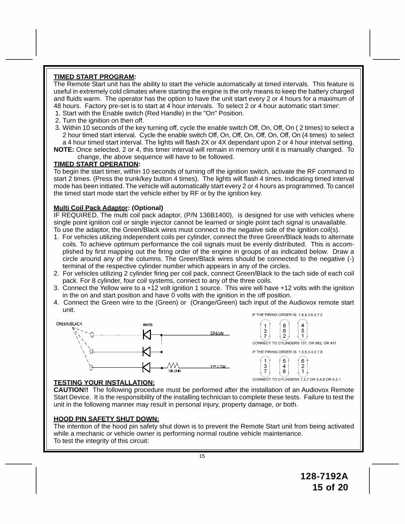
Multi Coil Pack Adaptor: (Optional)IF REQUIRED, The multi coil pack adaptor, (P/N 136B1400), is designed for use with vehicles wheresingle point ignition coil or single injector cannot be learned or single point tach signal is unavailable.To use the adaptor, the Green/Black wires must connect to the negative side of the ignition coil(s).1. For vehicles utilizing independent coils per cylinder, connect the three Green/Black leads to alternate
coils. To achieve optimum performance the coil signals must be evenly distributed. This is accom-plished by first mapping out the firing order of the engine in groups of as indicated below. Draw acircle around any of the columns. The Green/Black wires should be connected to the negative (-)terminal of the respective cylinder number which appears in any of the circles.
2. For vehicles utilizing 2 cylinder firing per coil pack, connect Green/Black to the tach side of each coilpack. For 8 cylinder, four coil systems, connect to any of the three coils.
3. Connect the Yellow wire to a +12 volt ignition 1 source. This wire will have +12 volts with the ignitionin the on and start position and have 0 volts with the ignition in the off position.
4. Connect the Green wire to the (Green) or (Orange/Green) tach input of the Audiovox remote startunit.
TESTING YOUR INSTALLATION:CAUTION!! The following procedure must be performed after the installation of an Audiovox RemoteStart Device. It is the responsibility of the installing technician to complete these tests. Failure to test theunit in the following manner may result in personal injury, property damage, or both.
HOOD PIN SAFETY SHUT DOWN:The intention of the hood pin safety shut down is to prevent the Remote Start unit from being activatedwhile a mechanic or vehicle owner is performing normal routine vehicle maintenance.To test the integrity of this circuit:
15
128-7192A16 of 20
1. With the driver's window in the down position, start the vehicle using the RF transmitter.2. Reach inside the car and pull the hood release.3. Raise the hood and confirm that the remote start unit shuts down.If the unit fails this test, recheck your pin switch connection to the Gray/Black wire of the Audiovox RemoteStart Unit.
DO NOT RELEASE THIS VEHICLE TO THE CONSUMER UNTIL YOU CONFIRM THEOPERATION OF THE HOOD PIN SAFETY SHUT DOWN FEATURE.
MANUAL SHUT DOWN / ENABLE CIRCUIT:The intent of the manual shut down / enable circuit is to allow the vehicle operator to prevent operation ofthe Remote Start Unit regardless of the RF transmitter operation.To test the integrity of the manual shut down / enable circuit:1. Place the control switch in the on (Closed To Ground) position.2. Start the vehicle using the RF transmitter.3. The vehicle should start and run under the control of the remote start unit.4. Move the switch to the off (Open From Ground) position, the vehicle should shut off.If the unit fails this test, recheck your enable switch connection to the Ground and the Black/White wire ofthe Audiovox Remote Start Unit. If you have a plug in enable switch, check that the two pin connector isfirmly seated in the mating connector on the control module.
DO NOT RELEASE THIS VEHICLE TO THE CONSUMER UNTIL YOU CONFIRM THEOPERATION OF THE MANUAL SHUT DOWN / ENABLE FEATURE.
NEUTRAL START SAFETY TEST:The intent of the neutral start switch is to prevent the vehicle from starting while the gear selector is in anyposition other than Park, or Neutral. When installing a Remote Start Device, it is imperative that the YellowStarter wire be connected to the ignition switch side of the Neutral Start Switch. Consideration for theplacement of a starter inhibit relay is important as well, and should be connected to the ignition switch sideof the Yellow Start Wire.To test the integrity of the Neutral Start Safety Circuit:1. Set the vehicle parking brake.2. Block the drive wheels to prevent vehicle movement.3. Temporarily disconnect the Brown/Black positive shut down wire from the vehicle's brake switch.4. Sitting in the vehicle, start the engine using the vehicle's ignition key.5. Step on the brake pedal and shift the gear selector into reverse.6. Allow the transmission to shift. When you feel the engine pull, do not move the gear selector just turn
the ignition switch off. DO NOT attempt to remove the key.7. Keeping the brake pedal depressed, activate the RF transmitter in an attempt to start the vehicle. The
car should not start.8. Repeat the above test this time move the gear selector to the drive position. If the unit attempts to start,
failing this test, recheck your Yellow Wire's connection. This wire must be connected to the ignitionswitch side of the Neutral Start Switch. If the vehicle you are working on does not have an ElectricalNeutral Safety Switch, it will be necessary to reconfigure the Remote Starts Wiring to accommodatethis vehicle. The information concerning the Mechanical Neutral Safety Switch provided below will helpyou to determine if the vehicle you are working on has this type of safety switch and will providealternate wiring methods to accommodate this situation.
16
128-7192A17 of 20
CAUTION!REMEMBER TO RECONNECT THE BROWN/BLACK WIRE TEMPORARILY
DISCONNECTED IN STEP 3
DO NOT RELEASE THIS VEHICLE TO THE CONSUMER UNTIL YOU CONFIRM THE OPERATIONOF THE NEUTRAL SAFETY START FEATURE.
MECHANICAL NEUTRAL SAFETY SWITCH CONSIDERATIONS:Mechanical neutral safety switch configurations differ slightly in that they do not offer the same level ofsafety when installing a remote start device. Often when the ignition switch is turned off while the gearselector is in any position other than park or neutral, the mechanical function will not allow the key to beturned to the start position or be removed from the ignition cylinder. This configuration prevents mechani-cal operation while the vehicle is in gear but offers no consideration for electrical operation. Because ofthis potential problem, this installation requires the additional connection of a safety wire from the remotestart device to the vehicle Park/Neutral ECM Input or the vehicle key in sensor. This connection willprevent remote start operation if the key is left in the ignition switch regardless of the gear selectorsposition.
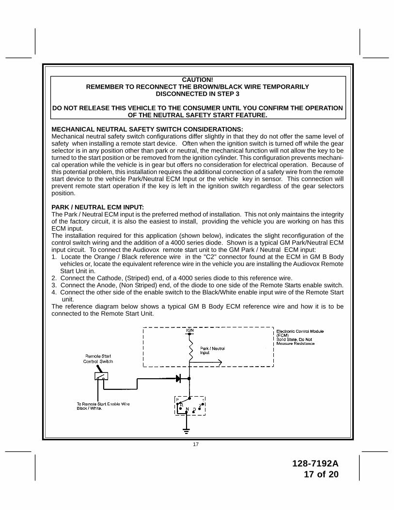
PARK / NEUTRAL ECM INPUT:The Park / Neutral ECM input is the preferred method of installation. This not only maintains the integrityof the factory circuit, it is also the easiest to install, providing the vehicle you are working on has thisECM input.The installation required for this application (shown below), indicates the slight reconfiguration of thecontrol switch wiring and the addition of a 4000 series diode. Shown is a typical GM Park/Neutral ECMinput circuit. To connect the Audiovox remote start unit to the GM Park / Neutral ECM input:1. Locate the Orange / Black reference wire in the "C2" connector found at the ECM in GM B Body
vehicles or, locate the equivalent reference wire in the vehicle you are installing the Audiovox RemoteStart Unit in.
2. Connect the Cathode, (Striped) end, of a 4000 series diode to this reference wire.3. Connect the Anode, (Non Striped) end, of the diode to one side of the Remote Starts enable switch.4. Connect the other side of the enable switch to the Black/White enable input wire of the Remote Start
unit.The reference diagram below shows a typical GM B Body ECM reference wire and how it is to beconnected to the Remote Start Unit.
17
128-7192A18 of 20
KEY IN SENSOR CIRCUITS:If the vehicle you are working on does not have or you cannot locate the ECM reference wire, there aretwo alternatives available. Although not preferred, the vehicle Key In Sensor may be reconfigured to allowa margin of safety and will prevent the vehicle with a Mechanical Neutral Start Switch from starting in gear.AUDIOVOX ADVISES THAT YOU MAINTAIN THE FACTORY CIRCUIT WHENEVER POSSIBLE. Thefollowing two circuits may be used only if the above circuit is not available.NOTE: When completing an installation using either of the following key in sensor circuits, if the operator
inserts the ignition key while the vehicle is running under the control of the Remote Start, thevehicle will shut down. This must be explained to the operator as it is in contrast to the normaloperation of a vehicle utilizing an electrical neutral start switch and is inconsistent with the opera-tors manual.
Additional information concerning Key In Sensor methods 1 & 2 are listed below and should be reviewedbefore considering either alternative.Method 1 will allow the safety required for the remote start unit and prevent the vehicle from starting whilein any gear other than Park or Neutral while the key is in the ignition cylinder however, if the key is left inthe ignition switch and the door is left opened, the added relay will be energized causing a 150mA drain onthe battery.Method 2 will allow the safety required for the remote start unit and prevent the vehicle from starting whilein any gear other than Park or Neutral while the key is in the ignition cylinder however, the original factorykey in chime module will not alert the owner that the key has been left in the ignition switch. In addition,this may also effect other warning tones such as the light on reminder.These situations should be carefully considered before altering the vehicle's wiring and must be fullyexplained to the consumer.
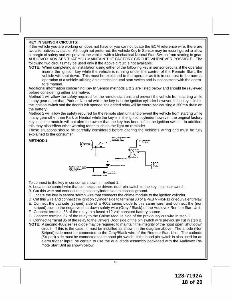
METHOD 1
To connect to the key in sensor as shown in method 1:A. Locate the control wire that connects the drivers door pin switch to the key in sensor switch.B. Cut this wire and connect the ignition cylinder side to chassis ground.C. Locate the key in sensor switch wire that connects the chime module to the ignition cylinder .D. Cut this wire and connect the ignition cylinder side to terminal 30 of a P&B VF45F11 or equivalent relay.E. Connect the cathode (striped) side of a 4002 series diode to this same wire, and connect the (non
striped) side to the negative shut down safety wire (Gray / Black) of the Audiovox Remote Start Unit.F. Connect terminal 86 of the relay to a fused +12 volt constant battery source.G. Connect terminal 87 of the relay to the Chime Module side of the previously cut wire in step D.H. Connect terminal 85 of the relay to the Drivers Door side of the pin switch wire previously cut in step B.NOTE: A second 4002 series diode may be required to maintain the integrity of the hood open, shut down
circuit. If this is the case, it must be installed as shown in the diagram above. The anode (NonStriped) side must be connected to the Gray/Black wire of the Remote Start Unit. The cathode(Striped) side must be connected to the hood pin switch. If the hood pin switch is also used for analarm trigger input, be certain to use the dual diode assembly packaged with the Audiovox Re-mote Start Unit as shown below.
18
128-7192A19 of 20
19
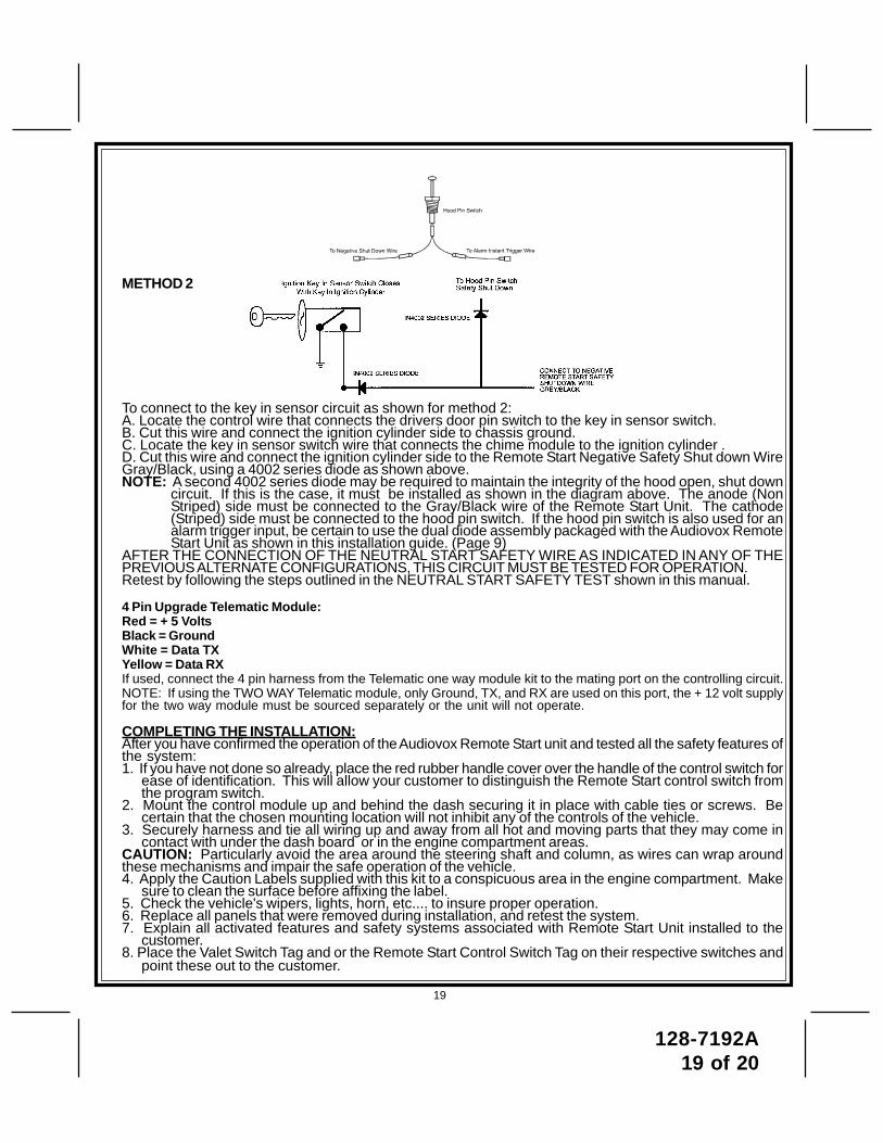
METHOD 2
To connect to the key in sensor circuit as shown for method 2:A. Locate the control wire that connects the drivers door pin switch to the key in sensor switch.B. Cut this wire and connect the ignition cylinder side to chassis ground.C. Locate the key in sensor switch wire that connects the chime module to the ignition cylinder .D. Cut this wire and connect the ignition cylinder side to the Remote Start Negative Safety Shut down WireGray/Black, using a 4002 series diode as shown above.NOTE: A second 4002 series diode may be required to maintain the integrity of the hood open, shut down
circuit. If this is the case, it must be installed as shown in the diagram above. The anode (NonStriped) side must be connected to the Gray/Black wire of the Remote Start Unit. The cathode(Striped) side must be connected to the hood pin switch. If the hood pin switch is also used for analarm trigger input, be certain to use the dual diode assembly packaged with the Audiovox RemoteStart Unit as shown in this installation guide. (Page 9)
AFTER THE CONNECTION OF THE NEUTRAL START SAFETY WIRE AS INDICATED IN ANY OF THEPREVIOUS ALTERNATE CONFIGURATIONS, THIS CIRCUIT MUST BE TESTED FOR OPERATION.Retest by following the steps outlined in the NEUTRAL START SAFETY TEST shown in this manual.
4 Pin Upgrade Telematic Module:Red = + 5 VoltsBlack = GroundWhite = Data TXYellow = Data RXIf used, connect the 4 pin harness from the Telematic one way module kit to the mating port on the controlling circuit.NOTE: If using the TWO WAY Telematic module, only Ground, TX, and RX are used on this port, the + 12 volt supplyfor the two way module must be sourced separately or the unit will not operate.
COMPLETING THE INSTALLATION:After you have confirmed the operation of the Audiovox Remote Start unit and tested all the safety features ofthe system:1. If you have not done so already, place the red rubber handle cover over the handle of the control switch for
ease of identification. This will allow your customer to distinguish the Remote Start control switch fromthe program switch.
2. Mount the control module up and behind the dash securing it in place with cable ties or screws. Becertain that the chosen mounting location will not inhibit any of the controls of the vehicle.
3. Securely harness and tie all wiring up and away from all hot and moving parts that they may come incontact with under the dash board or in the engine compartment areas.
CAUTION: Particularly avoid the area around the steering shaft and column, as wires can wrap aroundthese mechanisms and impair the safe operation of the vehicle.4. Apply the Caution Labels supplied with this kit to a conspicuous area in the engine compartment. Make
sure to clean the surface before affixing the label.5. Check the vehicle's wipers, lights, horn, etc.... to insure proper operation.6. Replace all panels that were removed during installation, and retest the system.7. Explain all activated features and safety systems associated with Remote Start Unit installed to the
customer.8. Place the Valet Switch Tag and or the Remote Start Control Switch Tag on their respective switches and
point these out to the customer.
128-7192A20 of 20
© 2006 Audiovox Electronics Corp., Hauppauge, N.Y. 11788 128-7192A