Embed Size (px)
Citation preview

3ME Series
Customer:
Customer
Part Number:
Innodisk
Part Number:
Innodisk
Model Name:
Date:
Innodisk
Approver
Customer
Approver

SATADOM-MV 3ME
2 Rev 1.4 TPS, Feb., 2015
Table of contents
LIST OF FIGURES .............................................................................................................................................. 6
1. PRODUCT OVERVIEW .................................................................................................................................. 7
1.1 INTRODUCTION OF INNODISK SATADOM-MV 3ME ....................................................................................... 7
1.2 PRODUCT VIEW AND MODELS ....................................................................................................................... 7
1.3 SATA INTERFACE ........................................................................................................................................ 7
2. PRODUCT SPECIFICATIONS ........................................................................................................................ 8
2.1 CAPACITY AND DEVICE PARAMETERS ........................................................................................................... 8
2.2 PERFORMANCE ............................................................................................................................................ 8
2.3 ELECTRICAL SPECIFICATIONS ....................................................................................................................... 8
2.3.1 Power Requirement ......................................................................................................................... 8
2.3.2 Power Consumption ........................................................................................................................ 8
2.4 ENVIRONMENTAL SPECIFICATIONS ................................................................................................................ 9
2.4.1 Temperature Ranges ....................................................................................................................... 9
2.4.2 Humidity ............................................................................................................................................ 9
2.4.3 Shock and Vibration ........................................................................................................................ 9
2.4.4 Mean Time between Failures (MTBF) ............................................................................................. 9
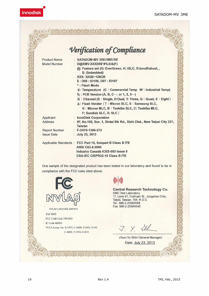
2.5 CE AND FCC COMPATIBILITY ....................................................................................................................... 9
2.6 ROHS COMPLIANCE .................................................................................................................................... 9
2.7 RELIABILITY .............................................................................................................................................. 10
2.8 TRANSFER MODE ...................................................................................................................................... 10
2.9 PIN ASSIGNMENT ....................................................................................................................................... 10
2.10 MECHANICAL DIMENSIONS ....................................................................................................................... 11
2.11 ASSEMBLY WEIGHT .................................................................................................................................. 11
2.12 SEEK TIME .............................................................................................................................................. 11
2.13 HOT PLUG ............................................................................................................................................... 11
2.14 NAND FLASH MEMORY ........................................................................................................................... 11
3. THEORY OF OPERATION ........................................................................................................................... 12
3.1 OVERVIEW ................................................................................................................................................. 12
3.2 SATA III CONTROLLER .............................................................................................................................. 12
3.3 ERROR DETECTION AND CORRECTION ........................................................................................................ 13
3.4 WEAR-LEVELING ....................................................................................................................................... 13
3.5 BAD BLOCKS MANAGEMENT ...................................................................................................................... 13
3.6 POWER CYCLING ....................................................................................................................................... 13
3.7 GARBAGE COLLECTION ............................................................................................................................. 13
4. INSTALLATION REQUIREMENTS .............................................................................................................. 14
4.1 SATADOM-MV 3ME PIN DIRECTIONS ....................................................................................................... 14

SATADOM-MV 3ME
3 Rev 1.4 TPS, Feb., 2015
4.2 ELECTRICAL CONNECTIONS FOR SATADOM-MV 3ME ............................................................................... 14
4.3 WRITE PROTECTION .................................................................................................................................. 14
4.4 DEVICE DRIVE ........................................................................................................................................... 15
4.5 PIN7 VCC ................................................................................................................................................. 15
5. PART NUMBER RULE ................................................................................................................................. 17

SATADOM-MV 3ME
4 Rev 1.4 TPS, Feb., 2015
REVISION HISTORY
Revision Description Date
Preliminary First Released May, 2013
1.0 Official release July, 2013
1.1 Performance update Nov., 2013
1.2 Update ME. drawing
Add power cable SPEC.
Feb., 2014
1.3 Modify PN rule. August, 2014
1.4 Remove Flash endurance SPEC.
Add RoHS/REACH declaration of conformity
Feb., 2015

SATADOM-MV 3ME
5 Rev 1.4 TPS, Feb., 2015
List of Tables TABLE 1: DEVICE PARAMETERS .............................................................................................................................. 8
TABLE 2: PERFORMANCE ....................................................................................................................................... 8
TABLE 3: INNODISK SATADOM-MV 3ME POWER REQUIREMENT ........................................................................... 8
TABLE 4: POWER CONSUMPTION ............................................................................................................................ 8
TABLE 5: TEMPERATURE RANGE FOR SATADOM-MV 3ME .................................................................................... 9
TABLE 6: SHOCK/VIBRATION TESTING FOR SATADOM-MV 3ME ............................................................................ 9
TABLE 7: SATADOM-MV 3ME MTBF ................................................................................................................... 9
TABLE 8: INNODISK SATADOM-MV 3ME PIN ASSIGNMENT .................................................................................. 10

SATADOM-MV 3ME
6 Rev 1.4 TPS, Feb., 2015
List of Figures FIGURE 1: INNODISK SATADOM-MV 3ME ............................................................................................................. 7
FIGURE 2: INNODISK SATADOM-MV 3ME BLOCK DIAGRAM ................................................................................ 12
FIGURE 3: SIGNAL SEGMENT AND POWER SEGMENT ............................................................................................. 14

SATADOM-MV 3ME
7 Rev 1.4 TPS, Feb., 2015
1. Product Overview
1.1 Introduction of Innodisk SATADOM-MV 3ME
Innodisk Serial ATA Disk on Module (SATADOM) supports SATA III standard (6.0Gb/s) interface with excellent
performance, and SATADOM-MV 3ME is designed as the smallest form factor size that could enhance
compatibility with various design applications. Particularly the 7th pin of standard SATA 7pin connector can
optionally be the built-in power VCC pin. In other words, it could be connected directly to the SATA on-board
socket on customers’ system without additional power cable. Besides, the booting time for operation and the
power consumption is less than hard disk drive (HDD). SATADOM-MV 3ME can work under harsh
environment compile with ATA protocol, no additional drives are required, and the SSD can be configured as a
boot device or data storage device.
1.2 Product View and Models
Innodisk SATADOM-MV 3ME is available in follow capacities within MLC flash ICs.
SATADOM-MV 3ME 8GB
SATADOM-MV 3ME 16GB
SATADOM-MV 3ME 32GB
SATADOM-MV 3ME 64GB
SATADOM-MV 3ME 128GB
Figure 1: Innodisk SATADOM-MV 3ME
1.3 SATA Interface
Innodisk SATADOM-MV 3ME supports SATA III interface, and compliant with SATA I and SATA II. SATA III
interface can work with Serial Attached SCSI (SAS) host system, which is used in server computer. Innodisk
SATADOM-MV 3ME is compliant with Serial ATA Gen 1, Gen 2 and Gen 3 specification (Gen 3 supports
1.5Gbps /3.0Gbps/6.0Gbps data rate). SATA connector uses a standard 7-pin signal segment.

SATADOM-MV 3ME
8 Rev 1.4 TPS, Feb., 2015
2. Product Specifications
2.1 Capacity and Device Parameters
SATADOM-MV 3ME device parameters are shown in Table 1.
Table 1: Device parameters
Capacity LBA Cylinders Heads Sectors User Capacity(MB)
8GB 15649200 15525 16 63 7,641
16GB 31277232 16383 16 63 15,272
32GB 62533296 16383 16 63 30,533
64GB 125045424 16383 16 63 61,057
128GB 250069680 16383 16 63 122,104
2.2 Performance
Burst Transfer Rate: 6.0Gbps
Table 2: Performance
Capacity 8GB 16GB 32GB 64GB 128GB
PN DESMV-XXXD07RX1XC DESMV -XXXD06RX1XC
Sequential
Read (max.) 90 MB/sec 240 MB/sec 450 MB/sec 460 MB/sec 460 MB/sec
Sequential
Write (max.) 13 MB/sec 40 MB/sec 80 MB/sec 150 MB/sec 160 MB/sec
Note: the information is based on CrystalDiskMark 3.01 with file size 1000MB test patent
2.3 Electrical Specifications
2.3.1 Power Requirement
Table 3: Innodisk SATADOM-MV 3ME Power Requirement
Item Symbol Rating Unit
Input voltage VIN +5 DC +- 5% V
2.3.2 Power Consumption
Table 4: Power Consumption
Mode Power Consumption (mA)
Read 180 (max.)
Write 200 (max.)
Idle 120 (max.)
* Target: 128GB SATADOM-MV 3ME

SATADOM-MV 3ME
9 Rev 1.4 TPS, Feb., 2015
2.4 Environmental Specifications
2.4.1 Temperature Ranges
Table 5: Temperature range for SATADOM-MV 3ME
Temperature Range
Operating Standard Grade: 0°C to +70°C
Industrial Grade: -40°C to +85°C
Storage -55°C to +95°C
2.4.2 Humidity
Relative Humidity: 10-95%, non-condensing
2.4.3 Shock and Vibration
Table 6: Shock/Vibration Testing for SATADOM-MV 3ME
Reliability Test Conditions Reference Standards
Vibration 7 Hz to 2K Hz, 20G, 3 axes IEC 68-2-6
Mechanical Shock Duration: 0.5ms, 1500 G, 3 axes IEC 68-2-27
2.4.4 Mean Time between Failures (MTBF)
Table 7 summarizes the MTBF prediction results for various SATADOM-MV 3ME configurations. The analysis
was performed using a RAM Commander™ failure rate prediction.
‧ Failure Rate: The total number of failures within an item population, divided by the total number of life
units expended by that population, during a particular measurement interval under stated condition.
‧ Mean Time between Failures (MTBF): A basic measure of reliability for repairable items: The mean
number of life units during which all parts of the item perform within their specified limits, during a particular
measurement interval under stated conditions.
Table 7: SATADOM-MV 3ME MTBF
Product Condition MTBF (Hours)
Innodisk SATADOM-MV 3ME Telcordia SR-332 GB, 25°C >3,000,000
2.5 CE and FCC Compatibility
SATADOM-MV 3ME conforms to CE and FCC requirements.
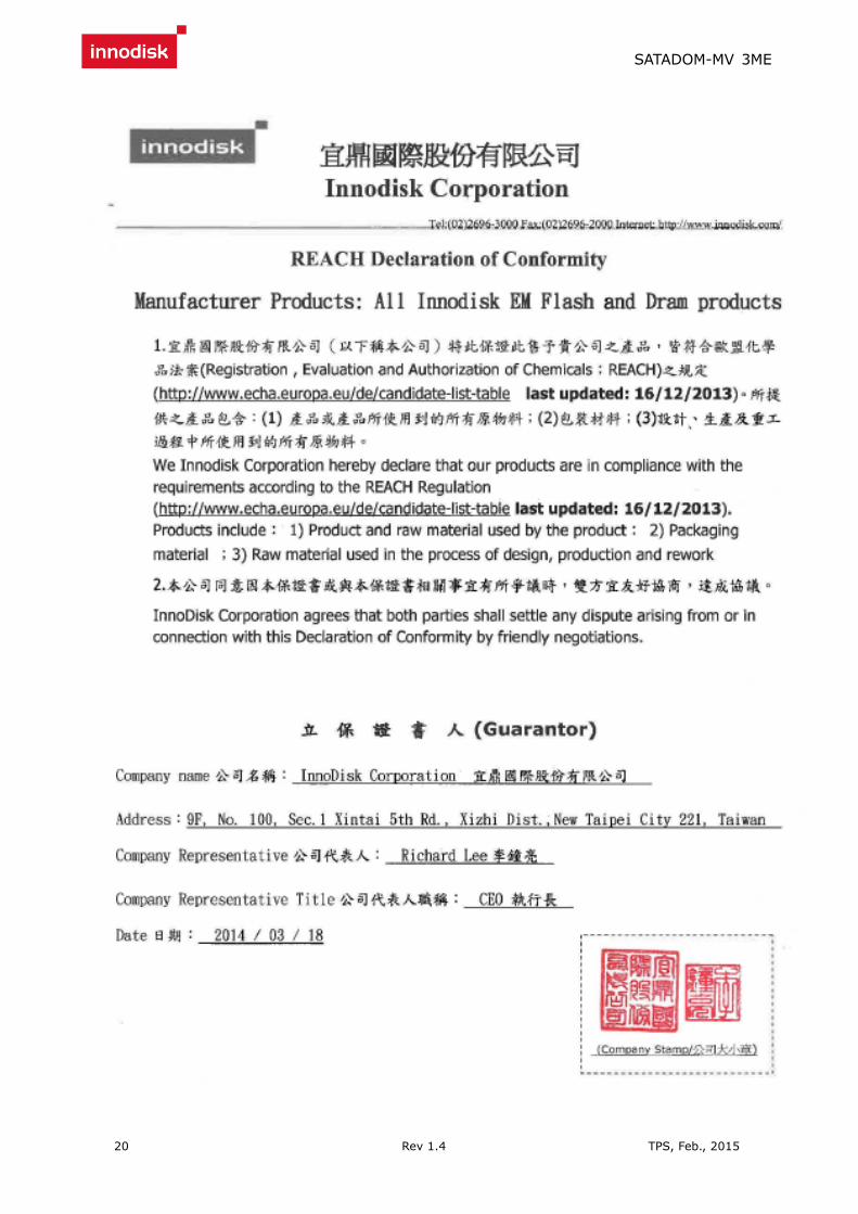
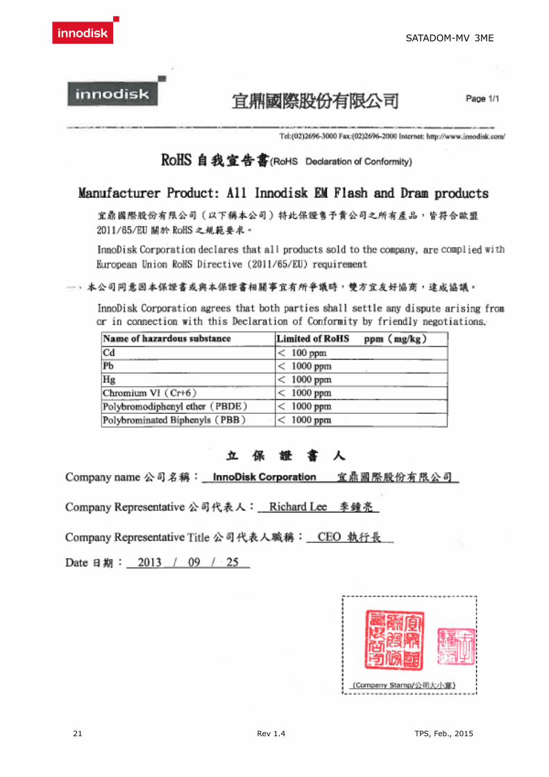
2.6 RoHS Compliance

SATADOM-MV 3ME
10 Rev 1.4 TPS, Feb., 2015
SATADOM-MV 3ME is fully compliant with RoHS directive.
2.7 Reliability
Parameter Value
Read Cycles Unlimited Read Cycles
Wear-Leveling Algorithm Support
Bad Blocks Management Support
Error Correct Code Support
TBW
16GB 43.2 (Sequential write)
32GB 86.4 (Sequential write)
64GB 172.8 (Sequential write)
128GB 345.6 (Sequential write)
2.8 Transfer Mode
SATADOM-MV 3ME support following transfer mode:
Serial ATA III 6.0Gbps
Serial ATA II 3.0Gbps
Serial ATA I 1.5Gbps
2.9 Pin Assignment
Innodisk SATADOM-MV 3ME uses a standard SATA pin-out. See Table 8 for SATADOM-MV 3ME pin
assignment.
Table 8: Innodisk SATADOM-MV 3ME Pin Assignment
Name Type Description
Pin 1 GND Shielding
Pin 2 A+ Differential signal to A
Differential signal to A- Pin 3 A- Differential signal to A-
Pin 4 GND Shielding
Pin 5 B- Differential signal to B-
Differential signal to B Pin 6 B+ Differential signal to B
Pin 7 GND/VCC
(+5V)
Shielding/Power*
SATADOM-MV 3ME
11 Rev 1.4 TPS, Feb., 2015
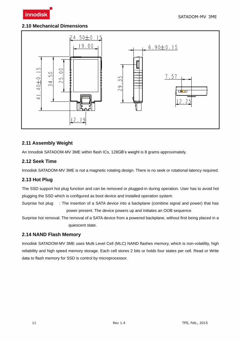
2.10 Mechanical Dimensions
2.11 Assembly Weight
An Innodisk SATADOM-MV 3ME within flash ICs, 128GB’s weight is 8 grams approximately.
2.12 Seek Time
Innodisk SATADOM-MV 3ME is not a magnetic rotating design. There is no seek or rotational latency required.
2.13 Hot Plug
The SSD support hot plug function and can be removed or plugged-in during operation. User has to avoid hot
plugging the SSD which is configured as boot device and installed operation system.
Surprise hot plug : The insertion of a SATA device into a backplane (combine signal and power) that has
power present. The device powers up and initiates an OOB sequence.
Surprise hot removal: The removal of a SATA device from a powered backplane, without first being placed in a
quiescent state.
2.14 NAND Flash Memory
Innodisk SATADOM-MV 3ME uses Multi Level Cell (MLC) NAND flashes memory, which is non-volatility, high
reliability and high speed memory storage. Each cell stores 2 bits or holds four states per cell. Read or Write
data to flash memory for SSD is control by microprocessor.

SATADOM-MV 3ME
12 Rev 1.4 TPS, Feb., 2015
3. Theory of Operation
3.1 Overview
Figure 2 shows the operation of Innodisk SATADOM-MV 3ME from the system level, including the major
hardware blocks.
Figure 2: Innodisk SATADOM-MV 3ME Block Diagram
Innodisk SATADOM-MV 3ME integrates a SATA III controller and NAND flash memories. Communication with
the host occurs through the host interface, using the standard ATA protocol. Communication with the flash
device(s) occurs through the flash interface.
3.2 SATA III Controller
Innodisk SATADOM-MV 3ME is designed with ID 106, a SATA III 6.0Gbps (Gen. 3) controller. The Serial ATA
physical, link and transport layers are compliant with Serial ATA Gen 1, Gen 2 and Gen 3 specification (Gen 3
supports 1.5Gbps/3.0Gbps/6.0Gbps data rate). The controller has 4 channels for flash interface.

SATADOM-MV 3ME
13 Rev 1.4 TPS, Feb., 2015
3.3 Error Detection and Correction
Highly sophisticated Error Correction Code algorithms are implemented. The ECC unit consists of the Parity
Unit (parity-byte generation) and the Syndrome Unit (syndrome-byte computation). This unit implements an
algorithm that can correct 40 bits per 1024 bytes in an ECC block. Code-byte generation during write
operations, as well as error detection during read operation, is implemented on the fly without any speed
penalties.
3.4 Wear-Leveling
Flash memory can be erased within a limited number of times. This number is called the erase cycle limit or
write endurance limit and is defined by the flash array vendor. The erase cycle limit applies to each individual
erase block in the flash device.
Innodisk SATADOM-MV 3ME uses a static wear-leveling algorithm to ensure that consecutive writes of a
specific sector are not written physically to the same page/block in the flash. This spreads flash media usage
evenly across all pages, thereby extending flash lifetime.
3.5 Bad Blocks Management
Bad Blocks are blocks that contain one or more invalid bits whose reliability are not guaranteed. The Bad
Blocks may be presented while the SSD is shipped, or may develop during the life time of the SSD. When the
Bad Blocks is detected, it will be flagged, and not be used anymore. The SSD implement Bad Blocks
management, Bad Blocks replacement, Error Correct Code to avoid data error occurred. The functions will be
enabled automatically to transfer data from Bad Blocks to spare blocks, and correct error bit.
3.6 Power Cycling
Innodisk’s power cycling management is a comprehensive data protection mechanism that functions before
and after a sudden power outage to SSD. Low-power detection terminates data writing before an abnormal
power-off, while table-remapping after power-on deletes corrupt data and maintains data integrity. Innodisk’s
power cycling provides effective power cycling management, preventing data stored in flash from degrading
with use.
3.7 Garbage Collection
Garbage collection is used to maintain data consistency and perform continual data cleansing on SSDs. It runs
as a background process, freeing up valuable controller resources while sorting good data into available blocks,
and deleting bad blocks. It also significantly reduces write operations to the drive, thereby increasing the SSD’s
speed and lifespan.

SATADOM-MV 3ME
14 Rev 1.4 TPS, Feb., 2015
4. Installation Requirements
4.1 SATADOM-MV 3ME Pin Directions
* All SATADOM Pin 7 with power is separate model, with different PN
Figure 3: Signal Segment and Power Segment
4.2 Electrical Connections for SATADOM-MV 3ME
A Serial ATA device may be either directly connected to a host or connected to a host through a cable. For
connection via cable, the cable should be no longer than 1meter. The SATA interface has a separate connector
for the power supply. Please refer to the pin description for further details.
4.3 Write Protection
SATADOM-MV 3ME within the write-protect function could prevent the device from modification and deletion.
Write-protected data could only be read, that is, users could not write to it, edit it, append data to it, or delete it.
When users would like to make sure that neither themselves nor others could modify or destroy the file, users
could switch on write-protection. Thus, SATADOM-MV 3ME could process write-protect mechanism and
disable flash memory to be written-in any data. Only while the system power-off, users could switch on
write-protection. Write-protection could not be switched-on, after OS booting.

SATADOM-MV 3ME
15 Rev 1.4 TPS, Feb., 2015
Figure 4: SATADOM-MV 3ME hardware write protect
4.4 Device Drive
No additional device drives are required. The Innodisk SATADOM-MV 3ME can be configured as a boot
device.
4.5 Pin7 VCC
Innodisk SATADOM series products have an optional design to provide power supply through the 7th Pin of
SATA connector, and customers DO NOT have to use the power cable for power supply. Such a cable-less
design of SATADOM series products with Pin7 VCC brings more convenience to customers’ system. The
followings are the points customers have to be careful of while designing in SATADOM series products with
Pin7 VCC.
SATADOM series products with Pin7 VCC is designed with a fuse (poly switch 500mA, 6V) on Pin7’s circuit.
Such a design could avoid any potential damage to customers’ system.
To have the advantages of SATADOM series with Pin7 VCC, and to avoid any potential damage to customers’
board designed with VCC power supply, Innodisk suggests that customers MUST design their board with a
fuse which should be designed before the SATA socket Pin7 VCC. In other words, customers are suggested
NOT TO layout 5V VCC to SATA socket on board directly. A circuit diagram example to explain this is shown as
below.

SATADOM-MV 3ME
16 Rev 1.4 TPS, Feb., 2015
4.6 Power cable
A power cable is shipped with each SATADOM product, which has standard 4pins power
connector and special 3 pins power connector for SATADOM. The male and female power
connector of SATADOM have foolproof design to avoid misconnection, please check it before
power on.
* PN end with F is SATADOM Pin 7 with power supply version, which doesn’t provide power
cable.

SATADOM-MV 3ME
17 Rev 1.4 TPS, Feb., 2015
5. Part Number Rule
CODE
1 2 3 4 5 6 7 8 9 10 11 12 13 14 15 16 17 18 19 20 21
D E S M V - 3 2 G D 0 6 R C 1 Q C - X X X
Description Disk mSATA Regular
Capacity Controller Flash Mode
Operation Temp.
Internal Control
CH. Flash Type
- Customized Code
Definition
Code 1st (Disk) Code 14th (Operation Temperature)
D : Disk C: Standard Grade (0℃~ +70℃)
Code 2nd (Feature set) W: Industrial Grade (-40℃~ +85℃)
E : Embedded series Code 15th (Internal control)
Code 3rd ~5th (Form factor) 1~9: TSOP PCB version.
SMV: SATADOM-MV Code 16th (Channel of data transfer)
Code 7th ~9th (Capacity) S: Single Channel
08G:8GB, 16G:16G
B
32G: 32GB. 64G:
64GB
A28:
128GB D: Dual Channels
Code 10th ~12th (Controller) Q: Quad Channels
D06: ID106 Code 17th (Flash Type)
D07: ID107 C: Toshiba MLC
Code 13th (Flash mode) Code 18th (pin7 type)
R: Toshiba A19 Synchronous flash for 3ME/3MG-P/3MR series
F: Pin7 version (Optional)
Code 19th~21st (Customize code)

SATADOM-MV 3ME
18 Rev 1.4 TPS, Feb., 2015
Appendix
CE/FCC/RoHS
SATADOM-MV 3ME
19 Rev 1.4 TPS, Feb., 2015
SATADOM-MV 3ME
20 Rev 1.4 TPS, Feb., 2015
SATADOM-MV 3ME
21 Rev 1.4 TPS, Feb., 2015