Embed Size (px)
Citation preview
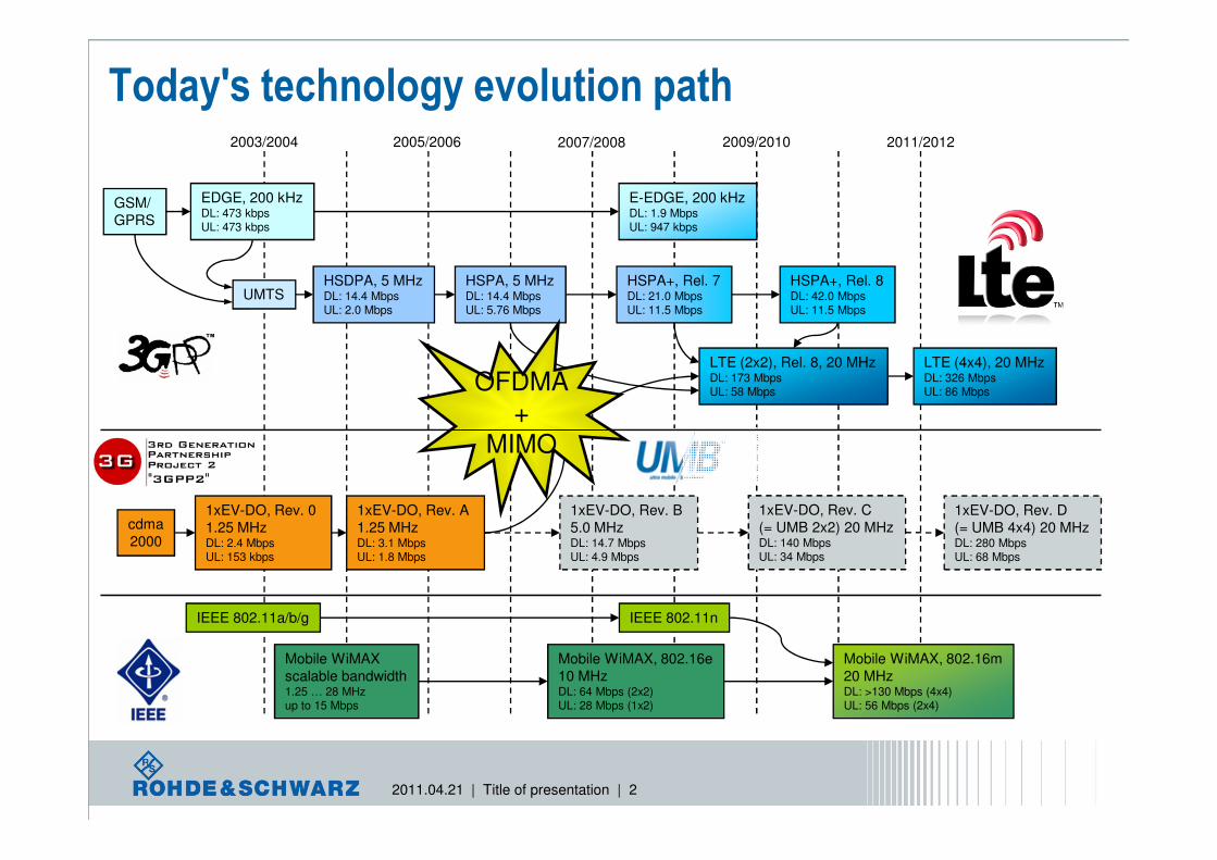
2009/2010
Today's technology evolution path
GSM/
GPRS
UMTS
EDGE, 200 kHzDL: 473 kbpsUL: 473 kbps
E-EDGE, 200 kHzDL: 1.9 MbpsUL: 947 kbps
HSDPA, 5 MHzDL: 14.4 MbpsUL: 2.0 Mbps
HSPA, 5 MHzDL: 14.4 MbpsUL: 5.76 Mbps
HSPA+, Rel. 7DL: 21.0 MbpsUL: 11.5 Mbps
2003/2004 2005/2006 2007/2008 2011/2012
LTE (2x2), Rel. 8, 20 MHzDL: 173 MbpsUL: 58 Mbps
LTE (4x4), 20 MHzDL: 326 MbpsUL: 86 Mbps
HSPA+, Rel. 8DL: 42.0 MbpsUL: 11.5 Mbps
OFDMA+
MIMO
2011.04.21 | Title of presentation | 2
cdma
2000
1xEV-DO, Rev. 0
1.25 MHzDL: 2.4 MbpsUL: 153 kbps
1xEV-DO, Rev. A
1.25 MHzDL: 3.1 MbpsUL: 1.8 Mbps
1xEV-DO, Rev. B
5.0 MHzDL: 14.7 MbpsUL: 4.9 Mbps
1xEV-DO, Rev. D
(= UMB 4x4) 20 MHzDL: 280 MbpsUL: 68 Mbps
Mobile WiMAX
scalable bandwidth1.25 … 28 MHzup to 15 Mbps
Mobile WiMAX, 802.16e
10 MHz DL: 64 Mbps (2x2)UL: 28 Mbps (1x2)
Mobile WiMAX, 802.16m
20 MHzDL: >130 Mbps (4x4)UL: 56 Mbps (2x4)
IEEE 802.11a/b/g IEEE 802.11n
1xEV-DO, Rev. C
(= UMB 2x2) 20 MHzDL: 140 MbpsUL: 34 Mbps
MIMO
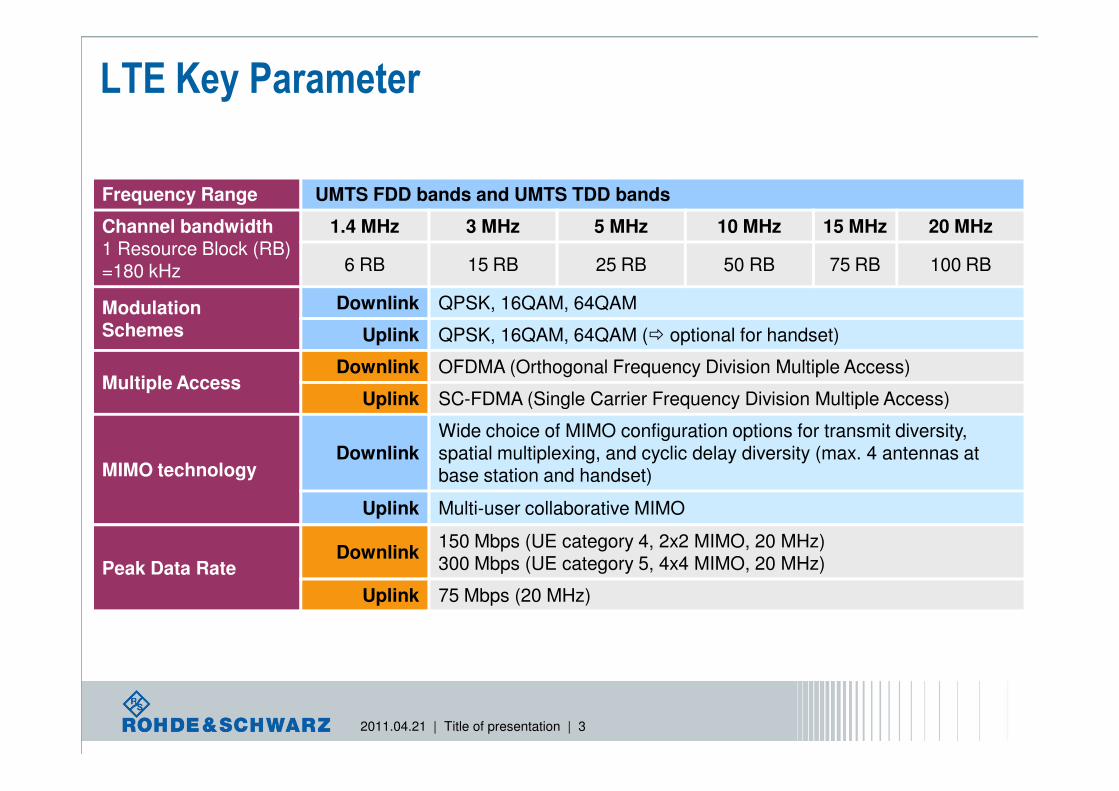
LTE Key Parameter
Frequency Range UMTS FDD bands and UMTS TDD bands
Channel bandwidth 1 Resource Block (RB)=180 kHz
1.4 MHz 3 MHz 5 MHz 10 MHz 15 MHz 20 MHz
6 RB 15 RB 25 RB 50 RB 75 RB 100 RB
Modulation Schemes
Downlink QPSK, 16QAM, 64QAM
Uplink QPSK, 16QAM, 64QAM (� optional for handset)
Multiple AccessDownlink OFDMA (Orthogonal Frequency Division Multiple Access)
Uplink SC-FDMA (Single Carrier Frequency Division Multiple Access)
2011.04.21 | Title of presentation | 3
Uplink SC-FDMA (Single Carrier Frequency Division Multiple Access)
MIMO technologyDownlink
Wide choice of MIMO configuration options for transmit diversity, spatial multiplexing, and cyclic delay diversity (max. 4 antennas at base station and handset)
Uplink Multi-user collaborative MIMO
Peak Data RateDownlink
150 Mbps (UE category 4, 2x2 MIMO, 20 MHz)300 Mbps (UE category 5, 4x4 MIMO, 20 MHz)
Uplink 75 Mbps (20 MHz)
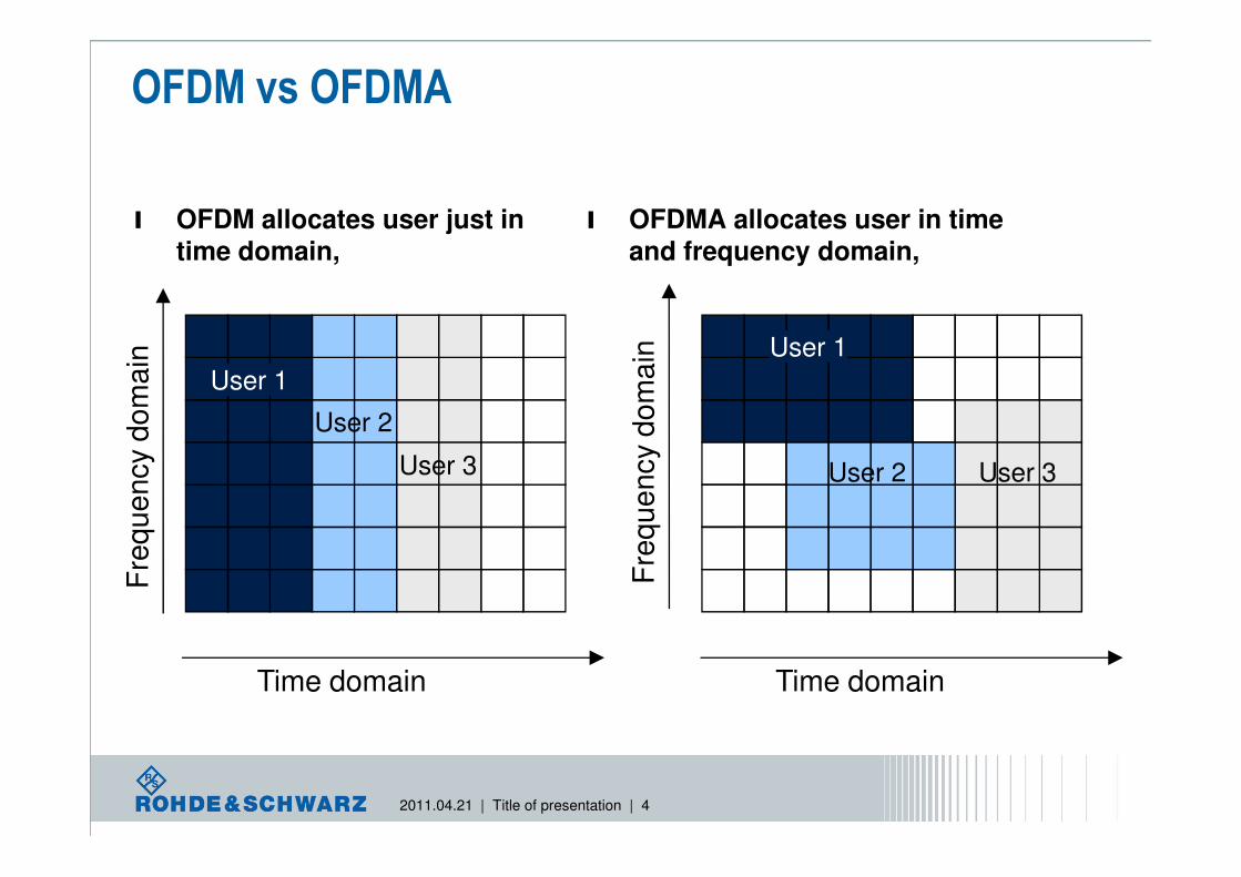
OFDM vs OFDMA
l OFDM allocates user just in
time domain,
l OFDMA allocates user in time
and frequency domain,
Fre
qu
en
cy d
om
ain
Fre
qu
en
cy d
om
ain
User 2
User 1
User 1
2011.04.21 | Title of presentation | 4
Time domain Time domain
Fre
qu
en
cy d
om
ain
Fre
qu
en
cy d
om
ain
User 3User 3 User 2
frequency
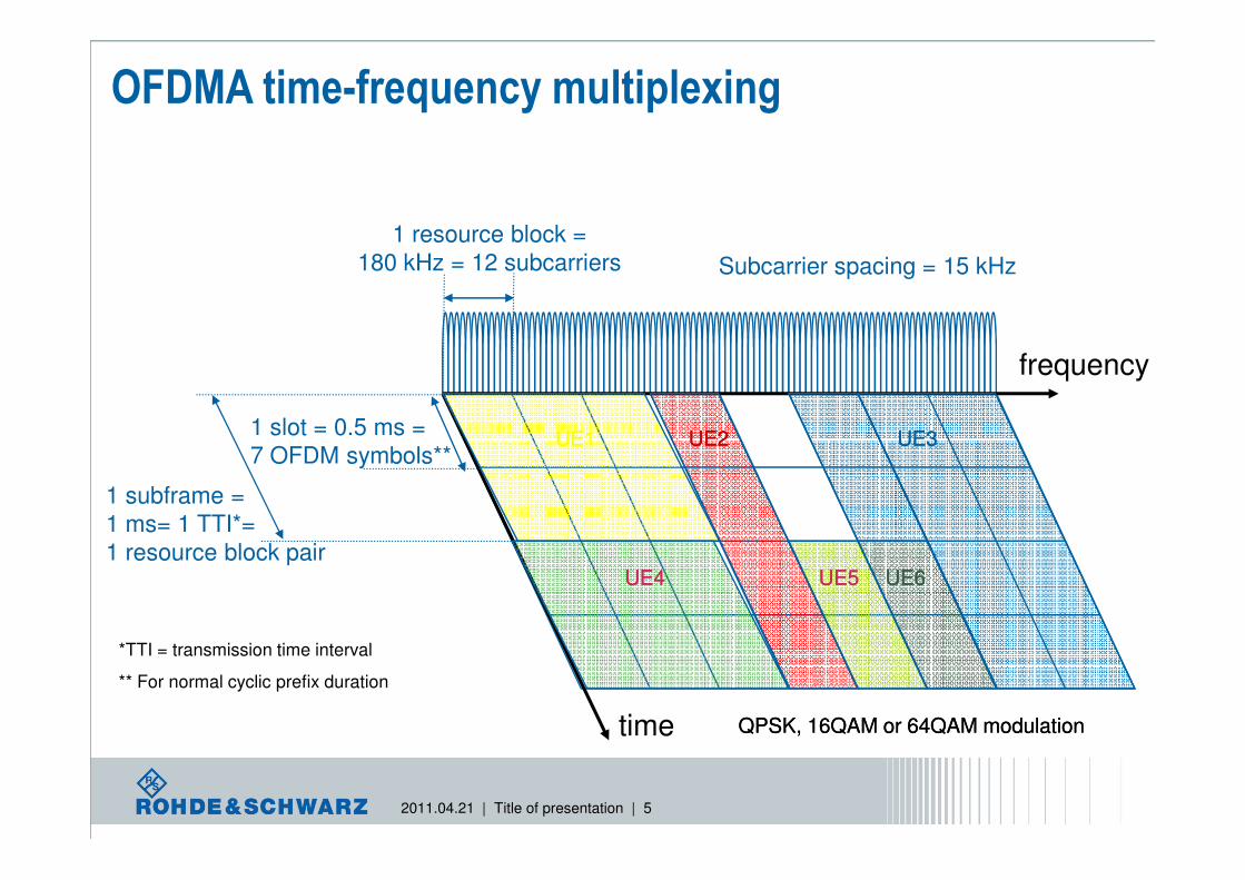
1 resource block =
180 kHz = 12 subcarriers
1 slot = 0.5 ms =
OFDMA time-frequency multiplexing
Subcarrier spacing = 15 kHz
UE1UE1 UE3UE3UE2UE2
2011.04.21 | Title of presentation | 5
time
1 slot = 0.5 ms =
7 OFDM symbols**
1 subframe =
1 ms= 1 TTI*=
1 resource block pair
*TTI = transmission time interval
** For normal cyclic prefix duration
QPSK, 16QAM or 64QAM modulationQPSK, 16QAM or 64QAM modulation
UE1UE1
UE4UE4
UE3UE3UE2UE2
UE5UE5 UE6UE6

Spectrum flexibility
TransmissionBandwidth [RB]
Transmission Bandwidth Configuration [RB]
Channel Bandwidth [MHz]
Re
so
urc
e b
loc
k
Ch
an
nel e
dg
e
Ch
an
ne
l ed
ge
• Sub-carrier Spacing : 15kHz
•
• 1RB = 12carrier
= 12 x15kHz = 180kHz
•Tx Bandwidth
ex) 180kHz * 50RB = 9MHz
2011.04.21 | Title of presentation | 6
DC carrier (downlink only)Active Resource Blocks
Channel bandwidth BWChannel [MHz] 1.4 3 5 10 15 20
Number of resource blocks 6 15 25 50 75 100

…
1 Subframe = 1 ms(Minimum TTI)
1 Slot, TSlot = 15360xTSample = 0.5 ms
#0
Downlink frame structure
#1 #2 #3 #19
1 Radio Frame, TFrame = 307200xTSample1) = 10 ms
#0 #1 #2 #3 #4 #5 #6 Usage of normal cyclic prefix is assumed
2011.04.21 | Title of presentation | 7
TSYMBOL ≈ 66.7 µs
CPf0 f1 f2
1/TSYMBOL=15 kHz
ff0 f1 f2
TCP ≈ 5.2, 4.7 µs
Example of 3 subcarrier within one OFDM symbol
1) Sampling Rate = 30.72 MHz � TSample = 1/(15000x2048) = 32.522 ns

Resource Allocation
l RE( Resource Element), 1symbol / 1 subcarrier
l RB(Resource Block), 최소 전송 단위l 1 RB=12 sub-carriers
12*15 kHz = 180 kHz @ Freq Domain
1 Time Slot (= 0.5 ms) @ time domain,
10 MHz (50RB) ���� 50 RB*180 kHz = 9.0 MHz + 1 unused DC subcarrier (= fCarrier) = 9.015 MHz
2011.04.21 | Title of presentation | 8

Reference signals (DL)
l 안테나별 reference signal pattern
l 2 antennas 경우 예시– Frequency domain 축 간격 = 6 subcarrier
– Time domain 축 간격 = 4 OFDM symbols � 4 RS / RB
Resource Block
2011.04.21 | Title of presentation | 9
Resource Block

DL Reference signal antennas
2011.04.21 | Title of presentation | 10

3GPP U-ETRA/LTE AdvancedRelease 10
Carrier
aggregationeSC- FDMA
4x4 MIMO (UL)
8x8 MIMO (DL)
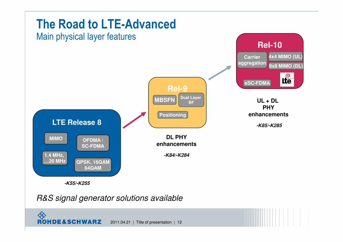
The Road to LTE-AdvancedMain physical layer features
LTE Release 8
Rel-10
Carrier
aggregation
4x4 MIMO (UL)
Rel-9
MBSFN
Positioning
Dual Layer
BF
8x8 MIMO (DL)
eSC-FDMA
UL + DL PHY
enhancements
2011.04.21 | Title of presentation | 12
LTE Release 8
MIMO OFDMA /SC-FDMA
1.4 MHz, …20 MHz QPSK, 16QAM
64QAM
DL PHYenhancements
R&S signal generator solutions available
-K55/-K255
-K84/-K284
-K85/-K285

LTE Release 10 features Physical layer
DL feature
Status
UL feature
l PUSCH/PUCCH synchronous transmission released
l Clustered PUSCH released
l PUCCH format 3 released
l Aperiodic SRS Q2/2012
l UL 2x2 MIMO Q2/2012
l Carrier Aggregation Q2/2012
Rel-10
2011.04.21 | Title of presentation | 13
DL feature
l Carrier Aggregation (up to 5x 20 MHz) released
l Cross-carrier scheduling for carrier aggregation released
l eICIC: general ABS support released
l DL 4x4 MIMO: generation of 4 TX-antennas released
(including FEC chain, layer mapping and precoding)
l Tx mode 9 Q2/2012
l CSI-RS Q2/2012
General features
l 2x2 and 4x2 MIMO fading simulation released

LTE Release 10 – eSC-FDMAWhat is it?
l eSC-FDMA = enhanced Single Carrier FDMA
l The uplink transmission
scheme remains
SC-FDMA
l The transmission of the
physical uplink shared
Rel-10
2011.04.21 | Title of presentation | 14
physical uplink shared
channel (PUSCH) uses
DFT precoding
l Two enhancements:
l PUCCH and PUSCH in the same subframe
l Non - contiguousdata transmission

LTE Release 10 – eSC-FDMAImpact on PHY layer
l Simultaneous transmission of PUSCH and PUCCHor a clustered PUSCH qualitatively causes multiple carriers in the frequency spectrum
l This leads to:
l Higher crest factor of the LTE-Advanced signal
Rel-10
2011.04.21 | Title of presentation | 15
l Higher crest factor of the LTE-Advanced signal
l Intermodulation products which might violate frequency masks
l Higher complexity of the base station receiver

LTE Release 10 – eSC-FDMA LTE settings in R&S®SMU200A
clustered PUSCH
simultaneous PUCCH/ PUSCH
Rel-10
PUCCH Format 3
2011.04.21 | Title of presentation | 16
clustered PUSCH
simultaneous PUCCH

LTE Release 10 – eSC-FDMAApplication example – intermodulation test
l LTE release 8
Rel-8
2011.04.21 | Title of presentation | 17
l PUSCH and PUCCH are not present at the same time
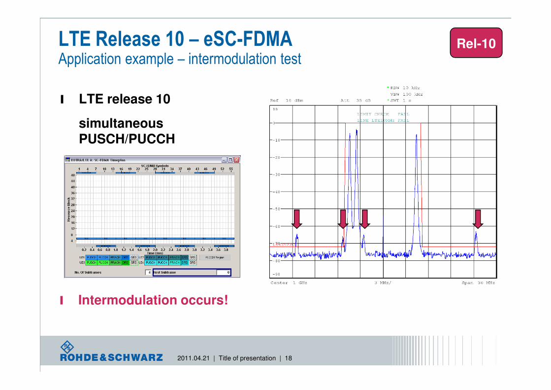
LTE Release 10 – eSC-FDMAApplication example – intermodulation test
l LTE release 10
simultaneousPUSCH/PUCCH
Rel-10
2011.04.21 | Title of presentation | 18
l Intermodulation occurs!
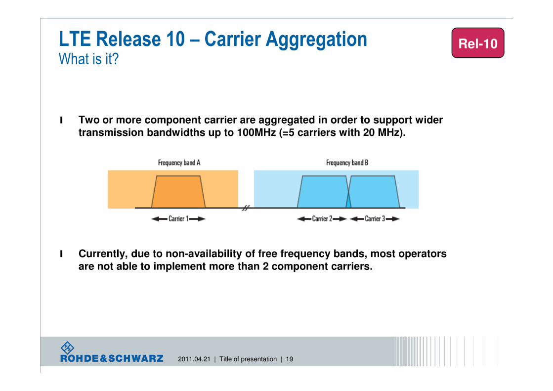
l Two or more component carrier are aggregated in order to support wider
transmission bandwidths up to 100MHz (=5 carriers with 20 MHz).
LTE Release 10 – Carrier AggregationWhat is it?
Rel-10
2011.04.21 | Title of presentation | 19
l Currently, due to non-availability of free frequency bands, most operators
are not able to implement more than 2 component carriers.

LTE Release 10 – Carrier Aggregation Impact on PHY layer
Time
Fre
qu
en
cy
PD
CC
H
PD
CC
H
1 subframe = 1 ms
1 slot = 0.5 ms
up to 3 (4) symbols per subframe
PDSCH PDSCH
l Variant I:
� PDCCH on a component carrier assigns PDSCH resources on the same component carrier (and PUSCH resources on a single linked UL component carrier)
–No carrier indicator field
l Cross-carrier scheduling
Rel-10
2011.04.21 | Title of presentation | 20
Variant (I) Variant (II)
PD
CC
H
PD
CC
H
PD
CC
H
PD
CC
HPDSCH
PDSCH
PDSCH
PDSCH
l Variant II:
� PDCCH on a component carrier can assign PDSCH or PUSCH resources in one of multiple component carriers using the carrier indicator field
–Rel-8 DCI formats extended with 1 to 3 bit carrier indicator field
l In both cases, limiting the number of blind decoding is desirable
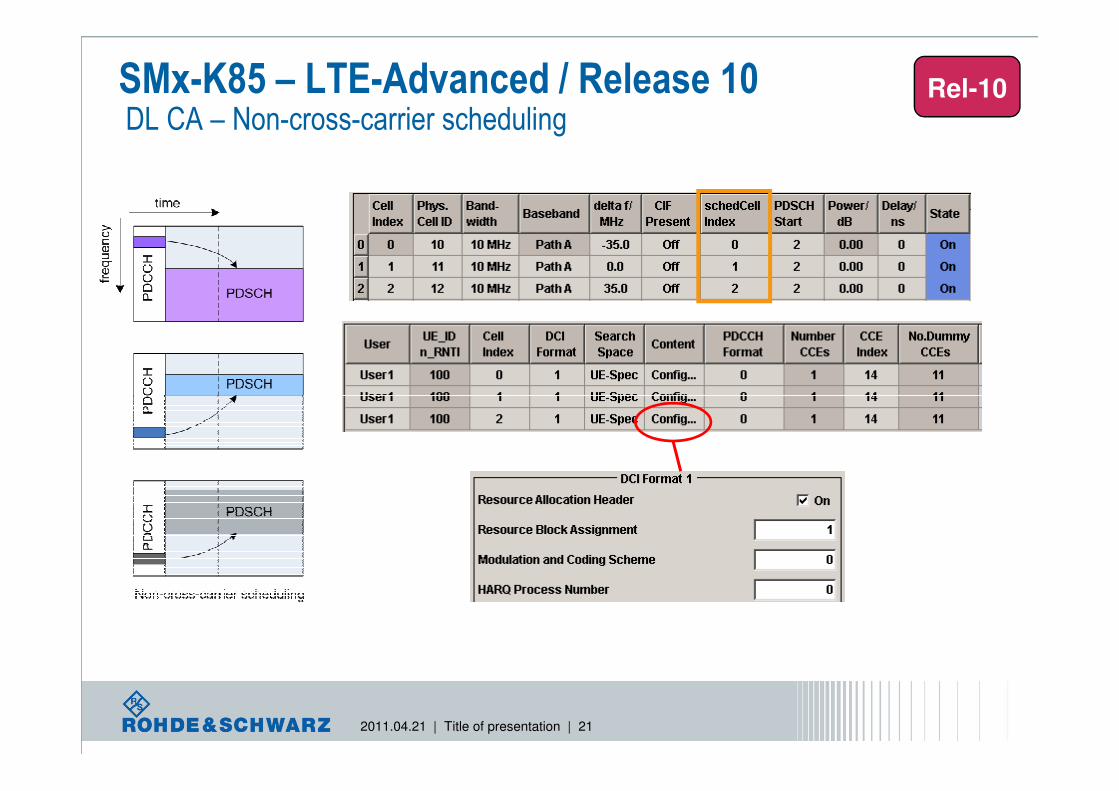
SMx-K85 – LTE-Advanced / Release 10DL CA – Non-cross-carrier scheduling
Rel-10
2011.04.21 | Title of presentation | 21
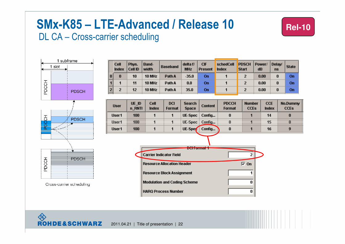
SMx-K85 – LTE-Advanced / Release 10DL CA – Cross-carrier scheduling
Rel-10
2011.04.21 | Title of presentation | 22
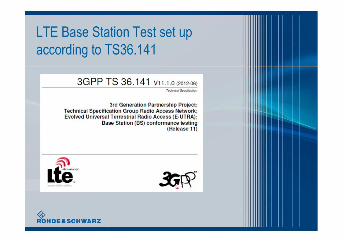
LTE Base Station Test set up
according to TS36.141

Transmitter Characteristics
▌ 기지국 측정 항목 소개TX 측정 항목 (TS36.141 Chapter 6)
- Chapter 6.2 : Base Station Output Power
- Chapter 6.3 : Output power dynamic range
- Chapter 6.5.1 : Frequency error
- Chapter 6.5.2 : Error vector magnitude (EVM)
- Chapter 6.5.3 : Time alignment between transmitter branches
- Chapter 6.5.4 : Down link RS power
2011.04.21 | Title of presentation | 24
- Chapter 6.5.4 : Down link RS power
- Chapter 6.6.1 : Occupied bandwidth
- Chapter 6.6.2 : Adjacent channel leakage ratio (ACLR)
- Chapter 6.6.3 : Operating band unwanted emissions
- Chapter 6.6.4 : Transmitter spurious emission

E-UTRA Test Modelsfor thansmitter Characteristics test
l General parameters used by E-UTRA test modell Duration is 10 subframes (10ms)
l Normal CP
l UE-specific reference signals are not used
l Virtual resource blocks of localized type, no intra-subframe hopping for
PDSCH
l Type of Test models
2011.04.21 | Title of presentation | 25
l Type of Test modelsl E-TM1.1/ 1.2/ 2/ 3.1/ 3.2/ 3.3
l Transmitter tests shall be according to one for the E-UTRA models

TS36.141 Transmitter CharacteristicsChapter 6.2 Base Station Output Power
Title Minimum Requirement in TS 36.141
Output
power
In normal conditions
within ±2 dB of manufacturer’s rated
output power
In extreme conditions
within ±2,5 dB of manufacturer’s rated
output power
▌Propose
-기지국 Maximum Output Power 가 Spec 에만족하는지측정▌Specification
2011.04.21 | Title of presentation | 26
.
▌Test Signal - E-TM 1.1
LTE Signal
▌Test set-up
Attenuator
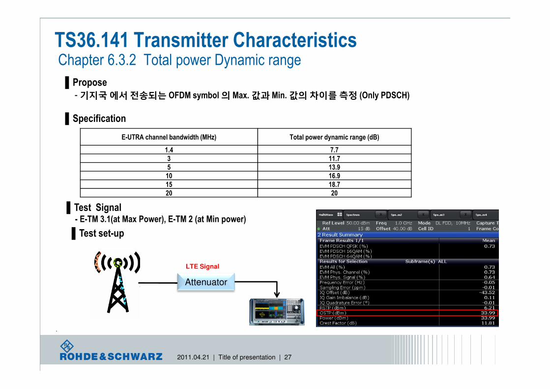
TS36.141 Transmitter Characteristics Chapter 6.3.2 Total power Dynamic range
▌Propose
-기지국에서전송되는 OFDM symbol 의 Max. 값과 Min. 값의차이를측정 (Only PDSCH)
▌Specification
E-UTRA channel bandwidth (MHz) Total power dynamic range (dB)
1.4 7.7
3 11.7
5 13.9
10 16.9
15 18.7
20 20
2011.04.21 | Title of presentation | 27
.
20 20
▌Test Signal - E-TM 3.1(at Max Power), E-TM 2 (at Min power)
LTE Signal
▌Test set-up
Attenuator

TS36.141 Transmitter Characteristics Chapter 6.5.1 Frequency error
▌Propose-기지국에할당된주파수와실제로전송되는주파수간의차이
(Data clock generation- key point)
▌Specification
BS class Accuracy
Wide Area BS ± 0.05 ppm
Local Area BS ± 0.1 ppm
Home BS ± 0.25 ppm
▌Test Signal
2011.04.21 | Title of presentation | 28
▌Test Signal - E-TM2, E-TM 3.1, E-TM3.2, E-TM3.3
LTE Signal
▌Test set-up
Attenuator

TS36.141 Transmitter Characteristics Chapter 6.5.2 : Error vector magnitude (EVM)
▌Propose
-기지국에서전송되는 LTE Signal 의 Quality 측정 (전송 Data Quality)
▌Specification
Modulation scheme for PDSCH Required EVM [%]
QPSK 17.5 %
16QAM 12.5 %
64QAM 8 %
▌Test Signal
2011.04.21 | Title of presentation | 29
▌Test Signal - E-TM 3.1(64QAM), E-TM 3.2(16QAM) , E-TM 3.3(QPSK), E-TM2(64QAM)
LTE Signal
▌Test set-up
Attenuator

TS36.141 Transmitter Characteristics Chapter 6.5.3 : Time alignment between transmitter branches
▌Propose-기지국전송 antenna간의 delay 를측정( Tx diversity, MIMO transmission, Carrier Aggregation)
▌Specification
- Two transmit antennas shall not exceed 65ns to 1.3us
▌Test Signal - E-TM 1.1
2011.04.21 | Title of presentation | 30
▌Test set-up
TX1Attenuator
Attenuator
LTE Signal
TX2 LTE Signal

TS36.141 Transmitter Characteristics Chapter 6.5.4 Downlink RS Power
▌Propose- Downlink Reference Symbol의 resource element power 측정
▌Specification- DL RS power shall be within ±±±± 2.1 dB of the DL RS power indicated on the DL-SCH
▌Test Signal - E-TM 1-1
▌Test set-up
2011.04.21 | Title of presentation | 31
Note that a repeater is a bi-directional device. The signal generator may need protection.
LTE Signal
▌Test set-up
Attenuator
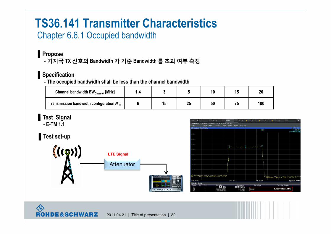
TS36.141 Transmitter Characteristics Chapter 6.6.1 Occupied bandwidth
▌Propose-기지국 TX 신호의 Bandwidth 가기준 Bandwidth 를초과여부측정
▌Specification- The occupied bandwidth shall be less than the channel bandwidth
Channel bandwidth BWChannel [MHz] 1.4 3 5 10 15 20
Transmission bandwidth configuration NRB 6 15 25 50 75 100
▌Test Signal
2011.04.21 | Title of presentation | 32
▌Test Signal - E-TM 1.1
LTE Signal
▌Test set-up
Attenuator

TS36.141 Transmitter Characteristics Chapter 6.6.2 : Adjacent channel rejection ratio (ACLR)
▌Propose- Pass-band 에있는기지국 center 주파수의 mean power 와바깥쪽에있는인접채널 mean power 의비율측정
▌Specification
E-UTRA transmitted signal channel bandwidth BWChannel
[MHz]
BS adjacent channel centre frequency offset below the first or above the last carrier centr
e frequency transmitted
Assumed adjacent channel carrier (informative)
Filter on the adjacent channel
frequency and corresponding
filter bandwidth
ACLR limit
1.4, 3.0, 5, 10, 15, 20 BWChannel E-UTRA of same BW Square (BWConfig) 45 dB2 x BWChannel E-UTRA of same BW Square (BWConfig) 45 dB
BWChannel /2 + 2.5 MHz 3.84 Mcps UTRA RRC (3.84 Mcps) 45 dBBWChannel /2 + 7.5 MHz 3.84 Mcps UTRA RRC (3.84 Mcps) 45 dB
NOTE 1: BWChannel and BWConfig are the channel bandwidth and transmission bandwidth configuration of the E-UTRA transmitted signal on the assigned channel frequency.
2011.04.21 | Title of presentation | 33
channel frequency.NOTE 2: The RRC filter shall be equivalent to the transmit pulse shape filter defined in TS 25.104 [6], with a chip rate as defined in this table.
▌Test Signal - E-TM 1.1/ E-TM1.2
LTE Signal
▌Test set-up
Attenuator
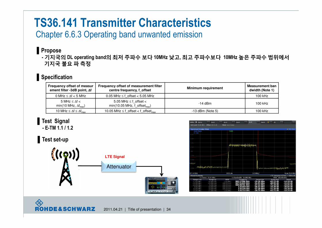
TS36.141 Transmitter Characteristics Chapter 6.6.3 Operating band unwanted emission
▌Propose-기지국의 DL operating band의최저주파수보다 10MHz 낮고, 최고주파수보다 10MHz 높은주파수범위에서기지국불요파측정
▌Specification
Frequency offset of measurement filter -3dB point, ∆∆∆∆f
Frequency offset of measurement filter centre frequency, f_offset
Minimum requirementMeasurement ban
dwidth (Note 1)
0 MHz ≤ ∆f < 5 MHz 0.05 MHz ≤ f_offset < 5.05 MHz 100 kHz
5 MHz ≤ ∆f < min(10 MHz, ∆fmax)
5.05 MHz ≤ f_offset < min(10.05 MHz, f_offsetmax)
-14 dBm 100 kHz
10 MHz ≤ ∆f ≤ ∆fmax 10.05 MHz ≤ f_offset < f_offsetmax -13 dBm (Note 5) 100 kHz
2011.04.21 | Title of presentation | 34
▌Test Signal - E-TM 1.1 / 1.2
LTE Signal
▌Test set-up
Attenuator

TS36.141 Transmitter Characteristics Chapter 6.6.4 Transmitter spurious emission
▌Propose- 9kHz 부터 12.75GHz 사이에서기지국의 Operating band unwanted emission 를제외한주파수주파수대역의기지국 TX 신호의불요파측정
▌Specification ( Category A)
Frequency range Maximum levelMeasurement Bandwi
dthNote
9kHz - 150kHz
-13 dBm
1 kHz Note 1150kHz - 30MHz 10 kHz Note 130MHz - 1GHz 100 kHz Note 1
1GHz - 12.75 GHz 1 MHz Note 2NOTE 1: Bandwidth as in ITU-R SM.329 [2] , s4.1
NOTE 2: Bandwidth as in ITU-R SM.329 [2] , s4.1. Upper frequency as in ITU-R SM.329 [2] , s2.5 table 1
2011.04.21 | Title of presentation | 35
NOTE 2: Bandwidth as in ITU-R SM.329 [2] , s4.1. Upper frequency as in ITU-R SM.329 [2] , s2.5 table 1
▌Test Signal - E-TM 1.1 / 1.2
LTE Signal
▌Test set-up
Attenuator

Thank you !!!