Embed Size (px)
Citation preview
8/10/2019 3DCreative Magazine Issue 033 May 2008
http://slidepdf.com/reader/full/3dcreative-magazine-issue-033-may-2008 1/224
ArticlesSWAY Studios latest campaign for Pontiac plus more!
InterviewsMathieu Aerni , Unexpected & Franz Steiner
GalleriesGreg Petchkovsky, Anton Bugaev & Malanjo plus more!
Making Of’s‘Eco-Wrestle’ by Simon Reeves plus more!
TutorialsPart 5 of our Bugatti Veyron Car Modelling Tutorial Series, plus more!
Issue033 May 2008 $4.50 / €3.25 / £2.25

8/10/2019 3DCreative Magazine Issue 033 May 2008
http://slidepdf.com/reader/full/3dcreative-magazine-issue-033-may-2008 2/224
page 2www.3dcreativemag.com Issue 033 May 2008
Contents
ContentsWhat’s in this month?
Mathieu AerniEnvironment & Character Artist For LucasArts
Franz SteinerCreative Director of Blutsbrüeder
Alexander KieselUnexpected’s Head of VFX & Managing Director
Jack of all tradesOr Master of One?
SWAYEnergizes Two-Spot Campaign for Pontiac
Galleries10 of the Best 3D Artworks
Stylised ChallengeThis Month’s Finalists & Last Month’s Making Ofs
ZBrushBeginner’s Guide to ZBrush: Part Four of Seven
Eco-WrestleProject Overview by Simon Reeves
Walther P99Project Overview by Romain Gouzenne
Grumman F-14 TomcatProject Overview by Stefan Biermann
Digital Art Masters:v2Free Chapter Book Promotion
FernProject Overview by CHEVisodes
RecruitmentJob Vacancies
About usZoo Publishing Information & Contacts
Bugatti VeyronFor 3ds Max, Maya, C4D & XSi
EditorialWell, we’re in a sunny mood
here and you’ll nd it reected
in the great content that we’ve
managed to pack into this
month’s issue for you! First
up, for all those LightWavers
who’ve been hanging onto
their seats for Parts 3-5 of the
Bugatti Veyron tutorial, then
wait no more – simply ick to
page 129 and get stuck into
the nishing modelling touches
to the Bugatti Veyron before we
move on to the Materials and
Shaders next month!
The sun must have really gone to our heads (we’re not used to such a
thing over here!) as we’re bringing you not one but four fantastic Making
Of articles this month, including one of our wonderfully bold cover image
by the newly formed CHEVisodes team, which encompasses some of
our favourite artists of today, including Patrick Beaulieau and Jonathan
Simard, so check out page 115 for the Making Of ‘Fern’ who is certainly
a character to behold!!
Now, when you spend half of your life emailing it comes as no surprise
that you’ll nd certain people who will lighten up your mailbox, and well,
the wonderfully friendly and superbly busy Alex Kiesl, the MD of the
dynamic studio, “Unexpected”, is one of those lovely people! In-between Alex’s manic schedule of lm shoots and project deadlines, we managed
to catch up with him for a chat about Unexpected’s projects and more,
and he has once again impressed with the fantastic interview that you’ll
nd on page 27. This is just the beginning from these determined guys,
so hold tight and stay-tuned for more amazing stuff coming from Stuttgart,
Germany!
We also have another great interview with Mathieu Aerni, who’s worked
for two of the biggest names in the games industry: Ubisoft and Lucas
Arts. So if you’re pining for a career in the games industry then this is
your man – head on over to page 6 for some behind the scenes chat
and learn from one of the pros! Another pick of the bunch this month must
surely be the interview with Franz Steiner, whose design company blends
– perfectly – high quality photography and CG in order to produce some
simply stunning visual effects for the fashion and advertising industries.
You won’t be disappointed when you see the stuff that they cook up at
Blutsbrueder Design and you’ll nd their work ooding page 17 and
beyond.
Finally, don’t forget to keep up with Wayne Robson in Part Four of the
ZBrush tutorial series this month and – oh yes, Enjoy! Cheers, Ed.
001
006
017
027
041
048
055
065
085
093
099
106
113
115
123
127
129
Editor Lynette Clee
LeadDesigner Chris Perrins
LayoutBobby Brown
Imogen Williams
MarketingLynette Clee
Free Stuff!Wherever you see
this symbol, click it todownload resources,
extras and even
movies!!
ContentLynette Clee
Tom Greenway
Richard Tilbury
Chris Perrins
ProofingJo Hargreaves
8/10/2019 3DCreative Magazine Issue 033 May 2008
http://slidepdf.com/reader/full/3dcreative-magazine-issue-033-may-2008 3/224
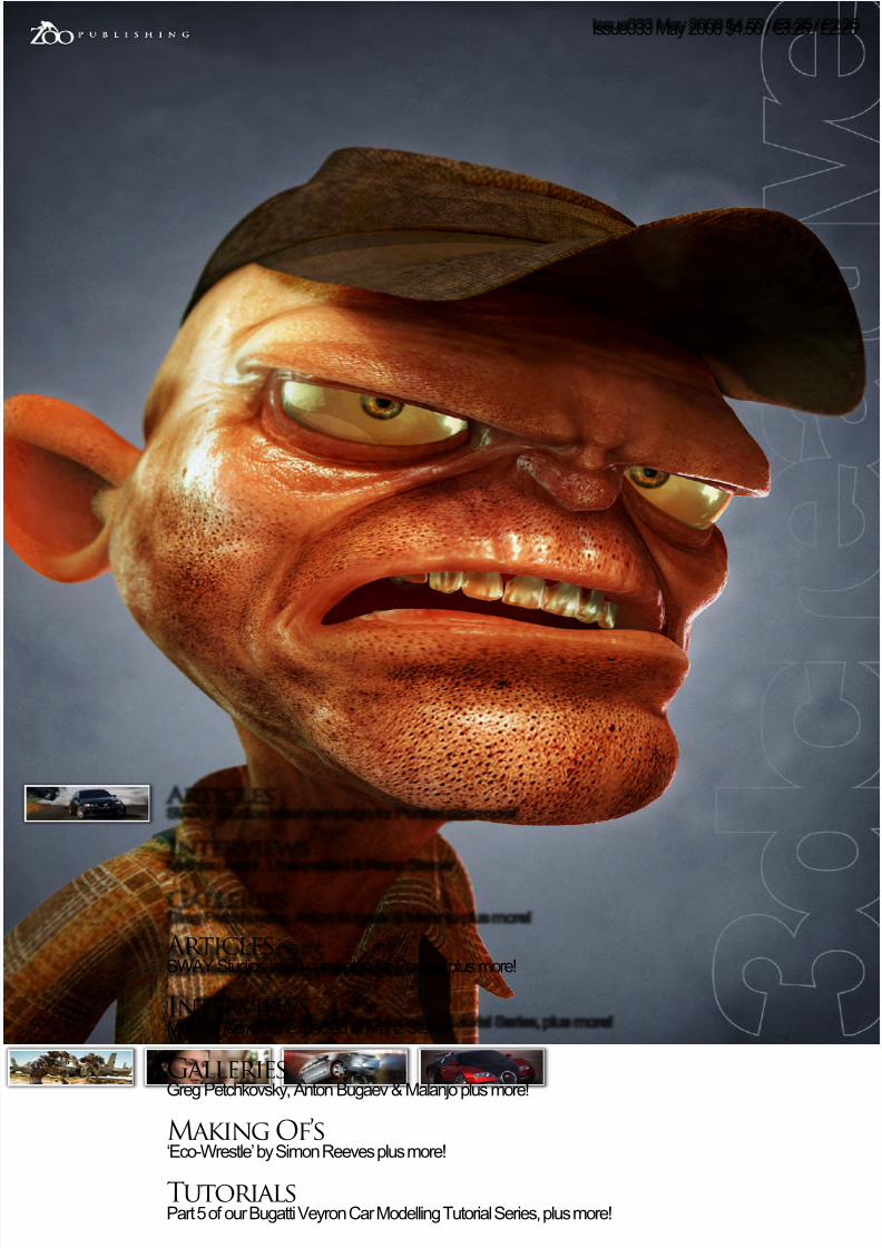
Setting up your PDF reader For optimum viewing of t he magazine, it is
recommended that you have the latest Acrobat
Reader installed. You can download it for free,
here: DOWNLOAD!
To view the many double-page spreads featured in 2DArtist magazine,
you can set the reader to display ‘two-up’, which will show double-
page spreads as one large landscape image:
1. Open the magazine in Reader;
2. Go to the View menu, then Page display ;3. Select Two-up Continuous, making sure that
Show Cover Page is also selected.
That’s it!
Get the most out of your
Magazine!If you’re having problems viewing the double-page spreads that we
feature in this magazine, follow this handy little guide on how to set
up your PDF reader!
8/10/2019 3DCreative Magazine Issue 033 May 2008
http://slidepdf.com/reader/full/3dcreative-magazine-issue-033-may-2008 4/224
page 4www.3dcreativemag.com Issue 033 May 2008
Contributors
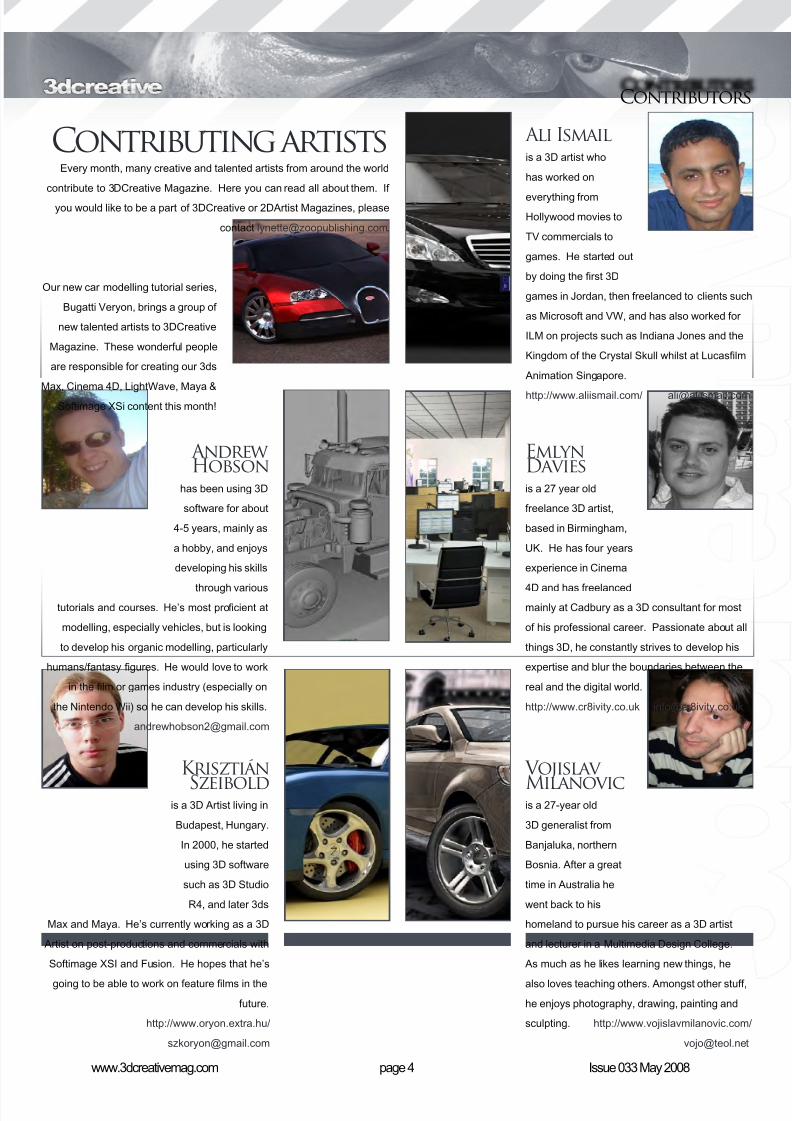
Contributing artistsEvery month, many creative and talented artists from around the world
contribute to 3DCreative Magazine. Here you can read all about them. If
you would like to be a part of 3DCreative or 2DArtist Magazines, please
contact [email protected].
Our new car modelling tutorial series,
Bugatti Veryon, brings a group of
new talented artists to 3DCreative
Magazine. These wonderful people
are responsible for creating our 3ds
Max, Cinema 4D, LightWave, Maya &
Softimage XSi content this month!
Ali Ismailis a 3D artist who
has worked on
everything from
Hollywood movies to
TV commercials to
games. He started out
by doing the rst 3D
games in Jordan, then freelanced to clients such
as Microsoft and VW, and has also worked for
ILM on projects such as Indiana Jones and the
Kingdom of the Crystal Skull whilst at Lucaslm
Animation Singapore.
http://www.aliismail.com/ [email protected]
EmlynDaviesis a 27 year old
freelance 3D artist,
based in Birmingham,
UK. He has four years
experience in Cinema
4D and has freelanced
mainly at Cadbury as a 3D consultant for most
of his professional career. Passionate about all
things 3D, he constantly strives to develop his
expertise and blur the boundaries between the
real and the digital world.
http://www.cr8ivity.co.uk [email protected]
Krisztián
Szeiboldis a 3D Artist living in
Budapest, Hungary.
In 2000, he started
using 3D software
such as 3D Studio
R4, and later 3ds
Max and Maya. He’s currently working as a 3D
Artist on post-productions and commercials with
Softimage XSI and Fusion. He hopes that he’s
going to be able to work on feature lms in the
future.
http://www.oryon.extra.hu/
AndrewHobson
has been using 3D
software for about
4-5 years, mainly as
a hobby, and enjoys
developing his skills
through various
tutorials and courses. He’s most procient at
modelling, especially vehicles, but is looking
to develop his organic modelling, particularly
humans/fantasy gures. He would love to work
in the lm or games industry (especially on
the Nintendo Wii) so he can develop his skills.
Vojislav
Milanovicis a 27-year old
3D generalist from
Banjaluka, northern
Bosnia. After a great
time in Australia he
went back to his
homeland to pursue his career as a 3D artist
and lecturer in a Multimedia Design College.
As much as he likes learning new things, he
also loves teaching others. Amongst other stuff,
he enjoys photography, drawing, painting and
sculpting. http://www.vojislavmilanovic.com/
8/10/2019 3DCreative Magazine Issue 033 May 2008
http://slidepdf.com/reader/full/3dcreative-magazine-issue-033-may-2008 5/224
page 5www.3dcreativemag.com Issue 033 May 2008page 5www.3dcreativemag.com Issue 000 Month 2007
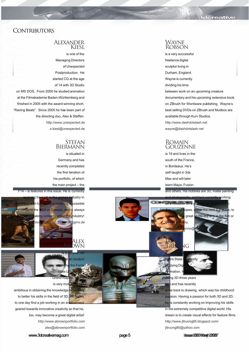
Contributors
Jacob
Truongis currently a junior at
Ferris State University
studying Digital
Animation. He started
doing 3D three years
ago and has recently
gone back to drawing, which was his childhood
passion. Having a passion for both 3D and 2D,
he is constantly working on improving his skills
in the extremely competitive digital world. His
dream is to create visual effects for feature lms.
http://www.jttruong85.blogspot.com/
Alex
Brownis a 22-year old
digital art student
attending the Ferris
State University in
Grand Rapids, MI. He
is very motivated and
ambitious in obtaining the knowledge necessary
to better his skills in the eld of 3D. He hopes
to one day nd a job working in an environment
geared towards innovative creativity so that he,
too, may become a great digital artist!
http://www.abrownportfolio.com
RomainGouzenneis 19 and lives in the
south of the France,
in Bordeaux. He’s
self-taught in 3ds
Max and will later
learn Maya, Fusion
and others. His hobbies are 3D, matte painting
and photography, and he’s currently working
as a modeller on a great short movie (out in
June!), and hopes, within the next 2-3 years, to
nd work in a great studio in Paris in the lm or
games industry.
StefanBiermann
is situated in
Germany and has
recently completed
the rst iteration of
his portfolio, of which
the main project – the
F14 – is featured in this issue. He is currently
applying for a job in the games industry in
Germany, with future plans involving a possible
life in the USA or Canada, and is always
interested in making contacts within the industry!
http://www.psistorm.org [email protected]
WayneRobsonis a very successful
freelance digitalsculptor living in
Durham, England.
Wayne is currently
dividing his time
between work on an upcoming creature
documentary and his upcoming extensive book
on ZBrush for Wordware publishing. Wayne’s
best selling DVDs on ZBrush and Mudbox are
available through Kurv Studios.
http://[email protected]
AlexanderKiesl
is one of the
Managing Directorsof Unexpected
Postproduction. He
started CG at the age
of 14 with 3D Studio
on MS DOS. From 2000 he studied animation
at the Filmakademie Baden-Württemberg and
nished in 2005 with the award-winning short,
“Racing Beats“. Since 2005 he has been part of
the directing duo, Alex & Steffen.
http://www.unexpected.de [email protected]
8/10/2019 3DCreative Magazine Issue 033 May 2008
http://slidepdf.com/reader/full/3dcreative-magazine-issue-033-may-2008 6/224
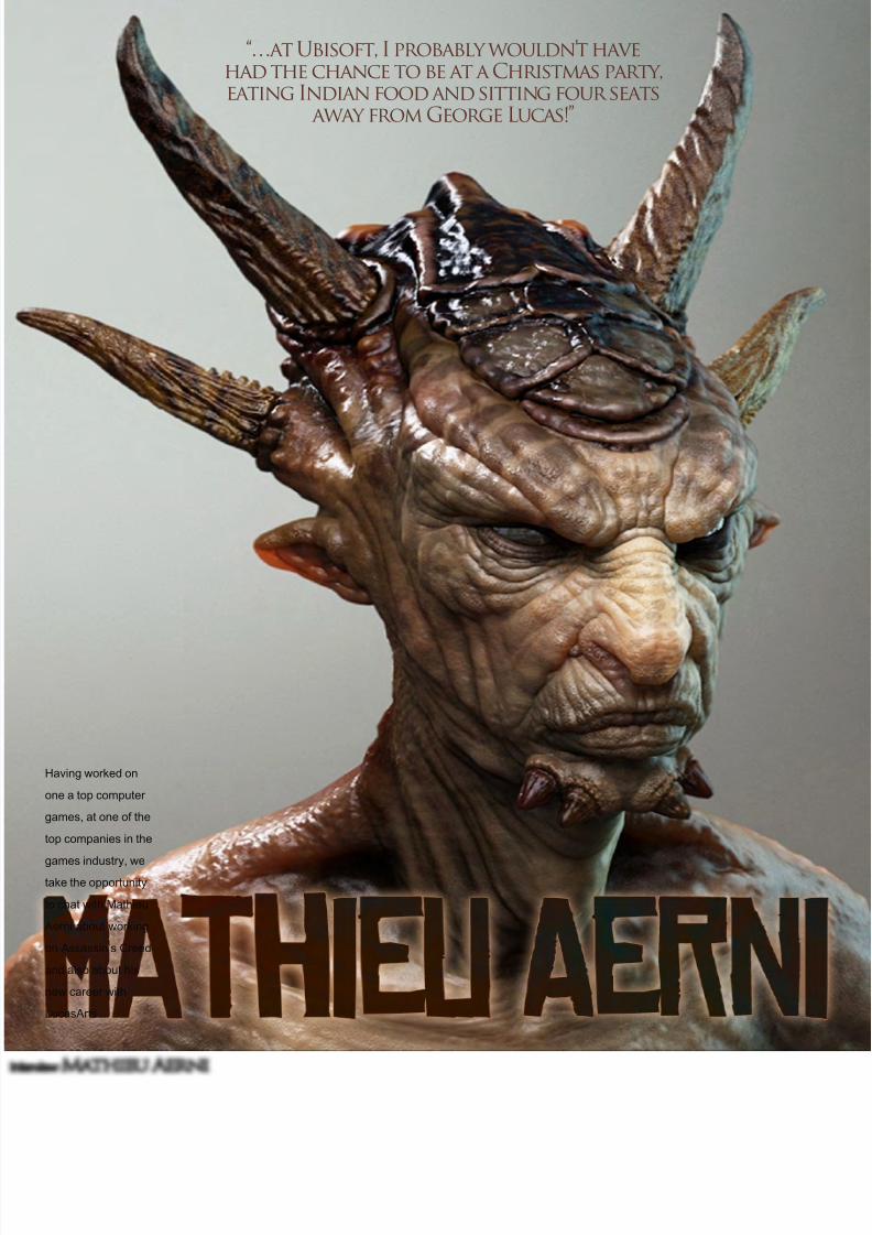
InterviewMathieu Aerni
Having worked on
one a top computer
games, at one of the
top companies in the
games industry, wetake the opportunity
to chat with Mathieu
Aerni about working
on Assassin’s Creed
and also about his
new career with
LucasArts ...
“…at Ubisoft, I probably wouldn’t havehad the chance to be at a Christmas party,eating Indian food and sitting four seats
away from George Lucas!”
8/10/2019 3DCreative Magazine Issue 033 May 2008
http://slidepdf.com/reader/full/3dcreative-magazine-issue-033-may-2008 7/224
page 7www.3dcreativemag.com Issue 033 May 2008
Mathieu Aerni Interview
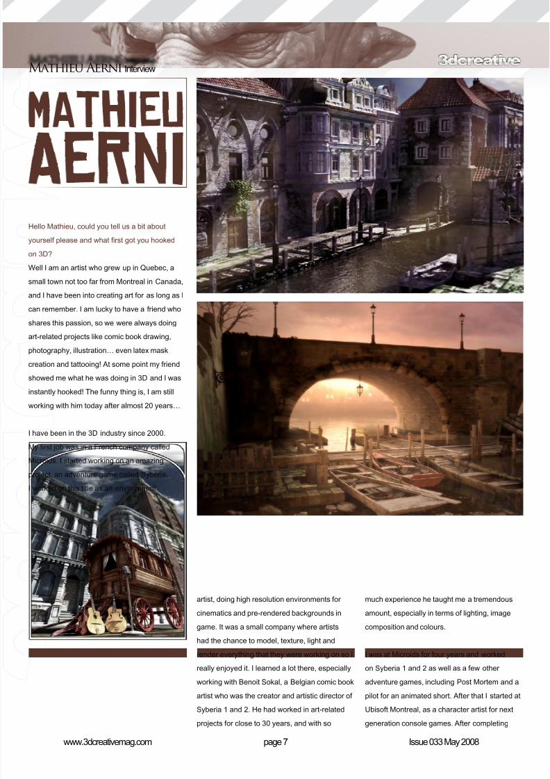
Hello Mathieu, could you tell us a bit about
yourself please and what rst got you hooked
on 3D?
Well I am an artist who grew up in Quebec, a
small town not too far from Montreal in Canada,
and I have been into creating art for as long as I
can remember. I am lucky to have a friend who
shares this passion, so we were always doing
art-related projects like comic book drawing,
photography, illustration… even latex mask
creation and tattooing! At some point my friend
showed me what he was doing in 3D and I was
instantly hooked! The funny thing is, I am still
working with him today after almost 20 years…
I have been in the 3D industry since 2000.
My rst job was in a French company called
Microids. I started working on an amazing
project, an adventure game called Syberia.
I worked on this title as an environment
artist, doing high resolution environments for
cinematics and pre-rendered backgrounds in
game. It was a small company where artists
had the chance to model, texture, light and
render everything that they were working on so I
really enjoyed it. I learned a lot there, especially
working with Benoit Sokal, a Belgian comic book
artist who was the creator and artistic director of
Syberia 1 and 2. He had worked in art-related
projects for close to 30 years, and with so
much experience he taught me a tremendous
amount, especially in terms of lighting, image
composition and colours.
I was at Microids for four years and worked
on Syberia 1 and 2 as well as a few other
adventure games, including Post Mortem and a
pilot for an animated short. After that I started at
Ubisoft Montreal, as a character artist for next
generation console games. After completing
8/10/2019 3DCreative Magazine Issue 033 May 2008
http://slidepdf.com/reader/full/3dcreative-magazine-issue-033-may-2008 8/224
InterviewMathieu Aerni
8/10/2019 3DCreative Magazine Issue 033 May 2008
http://slidepdf.com/reader/full/3dcreative-magazine-issue-033-may-2008 9/224
page 9www.3dcreativemag.com Issue 033 May 2008
Mathieu Aerni Interview
Assassin’s Creed, I came to LucasArts in
San Francisco and that’s where I am today. I
consider myself lucky to have had the chance
to always work on high resolution modelling andtexturing, both for environments and characters,
because it’s my favourite thing to do considering
the amount of detail and realism that it allows
me to create.
So having worked for what are the two biggest
names in the games industry, how does working
at LucasArts compare to Ubisoft?
Technically, the big difference is that LucasArts
is a private company. And I guess in amanagement position it must be very different,
but for me as an artist, it’s very similar. Both
places use pipelines that are very similar in
term of character creation, so my daily work is
not much different, except for the use of Maya
instead of 3ds Max and for the use of a bunch
of tools and software coming from ILM. Both
places are full of very talented and motivated
people, and I have learned a lot working a both.
The big differences for me are not directly
related to the work itself. For example, the
working environments could not be more
different; Ubisoft is in a old renovated textile
factory in a very crowded neighbourhood
of Montreal, while Lucaslm is in a newly
constructed building inside of a beautiful
national park, with lot of trees and a creek.
Both very motivating working environments,
just totally different. And of course at Ubisoft, I
probably wouldn’t have had the chance to be at
a Christmas party, eating Indian food and sitting
four seats away from George Lucas!
After just having just completed Assassin’s
Creed, I couldn’t help but notice some familiar
faces on your online portfolio. Could you tell us
how this job came about and about your role in
the creation of the game?
I had just nished working on the dinosaurs and
humans in Zbrush for the XBOX360 version of
Peter Jackson’s King Kong. The art director on
Assassin’s Creed saw my work and liked it, so
8/10/2019 3DCreative Magazine Issue 033 May 2008
http://slidepdf.com/reader/full/3dcreative-magazine-issue-033-may-2008 10/224
page 10www.3dcreativemag.com Issue 033 May 2008
InterviewMathieu Aerni
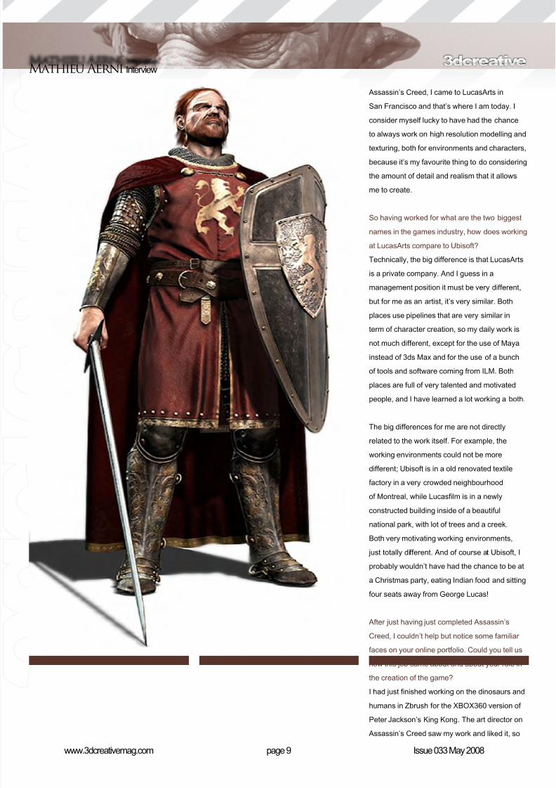
I was hired! Assassin’s Creed was an amazing
experience. We had about 150 characters to
create in a small amount of time, so it was
very intense but so motivating! My role was torst model and texture the high poly character
using 3ds Max for the base mesh and Zbrush,
and then bake it on a low poly mesh. For a
few specic models I also had to create some
beauty shots, so I tapped into my environment
artist experience to create interesting lighting
set-ups.
Were all 150 characters totally unique?
We created around 150 unique character yes,then afterwards we separated them in a lot of
assets and reused all those parts to create an
innite number of new characters. We could
combine various body parts and heads, and also
something like 60 texture variations in terms of
clothing and accessories. For example, I created
three totally unique Christian soldiers (a knight,
a simple ghter and an archer) for the Lionheart
faction. After they were validated, someone
else applied different textures variations tomy soldiers to make them look like the other
faction, the Templars. Then we created different
accessories, like weapon and helmets, and a
lot of different heads, and we ended up with
all those “generic” soldiers that you see in the
game. Alongside this, I also had to do important
characters, like Richard the Lionheart, who was
totally unique and had his own private textures.
Being set in the time of the Third Crusade, was
it an easy task nding “true to life” reference
material for creating the characters?
When I joined the team they had already
collected a huge selection of books and images
to use as references, so much of the job had
already been done in terms of nding reference
material. I had to do some research a couple of
times to nd some very precise references for
specic characters, but not much. So most of
the time I just had to go through all the existing
material and put together a folder of references
for the specic character I was working on. My
main concern was nding references for details,
8/10/2019 3DCreative Magazine Issue 033 May 2008
http://slidepdf.com/reader/full/3dcreative-magazine-issue-033-may-2008 11/224
page 11www.3dcreativemag.com Issue 033 May 2008
Mathieu Aerni Interview
like where the seams were located on clothes at
that time in history. We tried to make them look
very interesting while respecting the historical
references, and most of the credit for that goesto Patrick Desgrenier who was the concept artist
on our team.
And how long would it take on average to create
a character?
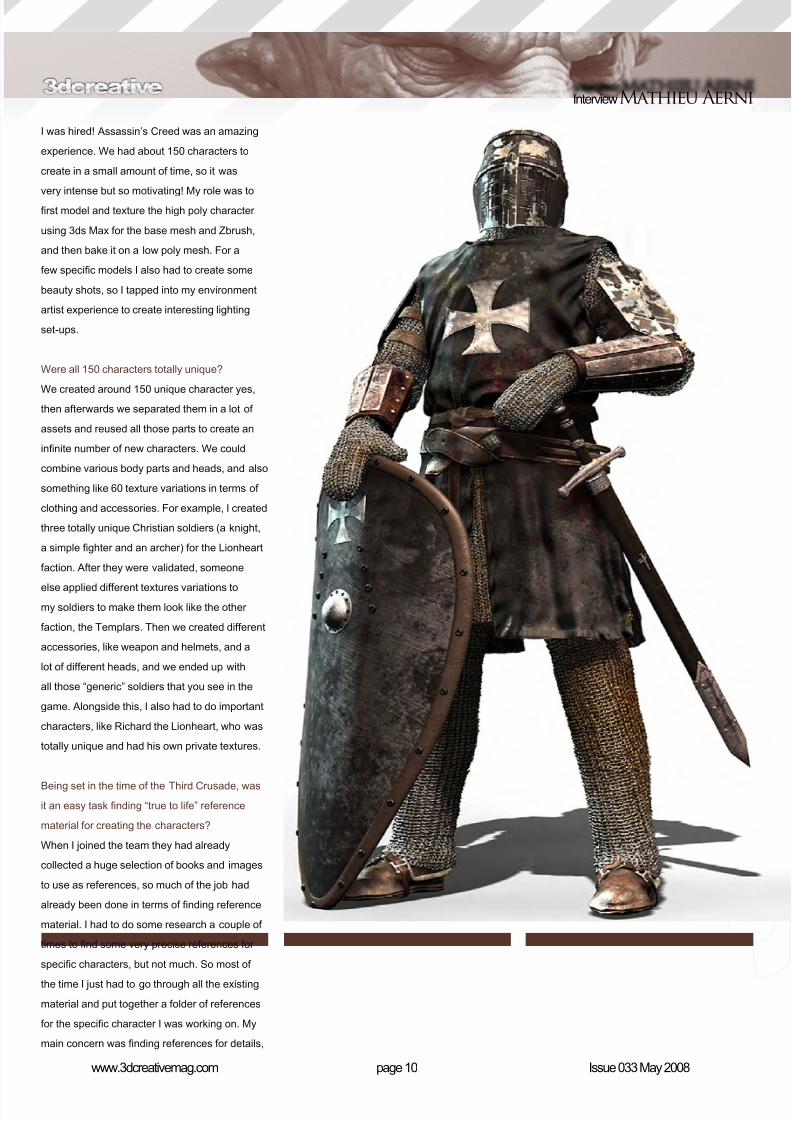
The average time for creating a character on
Assassin’s Creed was a week. That includes the
high and the low resolution mesh, both modelled
and textured. We had very tight deadlines
because we had so many characters to create!For important ones like Richard Lionheart and
Saladin, I had more time, around two weeks,
and I took some time on my own to light them
and pose them to make those “beauty shots”
that you can see in my portfolio.
So what are you working on at the moment?
I am working on a next generation project at
LucasArts but I’m afraid I can’t tell you much
about it at this stage.
Which artists inspire you?
So many of them! I grew up reading European
comic books and they are the main reason why
I began to be interested in art at a young age. I
am still a huge fan of those artists like Moebius,
Rosinsky, Bilal, Pratt, Manara, Loisel, Guarnido,
Gibrat and Frezzato, to name a few. I recently
bought a comic book called Billy Wild from Ceka
and Griffon, and Guillaume Griffon’s drawing
style really impresses me. I am also very
inspired by traditional artists like Rembrandt and
John Singer Sargent for the lighting and mood,
and Gerald Brom, Jordu Schell and Carlos
Huante for their imagination and the strong
character of their design. Richard McDonald
is also such an amazing sculptor; I just came
back from his exhibition in Las Vegas and I was
totally impressed.

8/10/2019 3DCreative Magazine Issue 033 May 2008
http://slidepdf.com/reader/full/3dcreative-magazine-issue-033-may-2008 12/224
InterviewMathieu Aerni
8/10/2019 3DCreative Magazine Issue 033 May 2008
http://slidepdf.com/reader/full/3dcreative-magazine-issue-033-may-2008 13/224
page 13www.3dcreativemag.com Issue 033 May 2008
Mathieu Aerni Interview
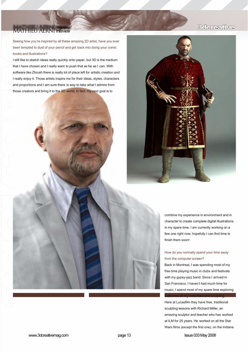
Seeing how you’re inspired by all these amazing 2D artist, have you ever
been tempted to dust of your pencil and get back into doing your comic
books and illustrations?
I still like to sketch ideas really quickly onto paper, but 3D is the mediumthat I have chosen and I really want to push that as far as I can. With
software like Zbrush there is really lot of place left for artistic creation and
I really enjoy it. Those artists inspire me for their ideas, styles, characters
and proportions and I am sure there is way to take what I admire from
those creators and bring it to the 3D world. In fact, my next goal is to
combine my experience in environment and in
character to create complete digital illustrations
in my spare time. I am currently working on a
few one right now; hopefully I can nd time to
nish them soon!
How do you normally spend your time away
from the computer screen?
Back in Montreal, I was spending most of my
free time playing music in clubs and festivals
with my gypsy-jazz band. Since I arrived in
San Francisco, I haven’t had much time for
music; I spend most of my spare time exploring
California on my motorbike and sculpting.
Here at Lucaslm they have free, traditional
sculpting lessons with Richard Miller, an
amazing sculptor and teacher who has worked
at ILM for 25 years. He worked on all the Star
Wars lms (except the rst one), on the Indiana
8/10/2019 3DCreative Magazine Issue 033 May 2008
http://slidepdf.com/reader/full/3dcreative-magazine-issue-033-may-2008 14/224
Jones movies and a lot of other great lms as
a concept sculptor and maquette creator. His
knowledge of anatomy is way above anyone
I have known in the past and I am learning so
much from him.
Sounds cool! You know, I’m really intrigued by
your gypsy jazz band. Can you tell us a bit about
this type of music and what instrument you
played? (Any chance of a sampler too?)
Sure! I play guitar. The type of music I play is
inspired by the great gypsy guitarist Django
Reinhardt, who was born in 1910 in Belgium
and died in 1953 in France. This guy was a
genius - he basically revolutionised the way
guitar is played. He was an incredible virtuoso,
playing with lot of inspiration and incredible
speed, even if he only had two ngers left on
his left hand (three including the thumb) after
he was severely burned. He was playing swing,
but with a lot of inspiration from his gypsy roots.
The result is a very energetic style of swing call
gypsy swing or Jazz Manouche. This style has
become more well-known recently, especially
since the animated movie Les Triplettes de
Belleville uses a lot of music inspired by that
style. We can actually see a cartoon Django
Reinhardt playing guitar at the very beginning of
that movie. You can listen to a few samples of
us playing on the band’s MySpace site:
http://www.myspace.com/gadjoswing
It has been a really pleasure getting to know
a bit about you Mathieu, but one last question
before we wrap things up. If I were to work
beside you for a whole day, what one thing
would I learn about you?
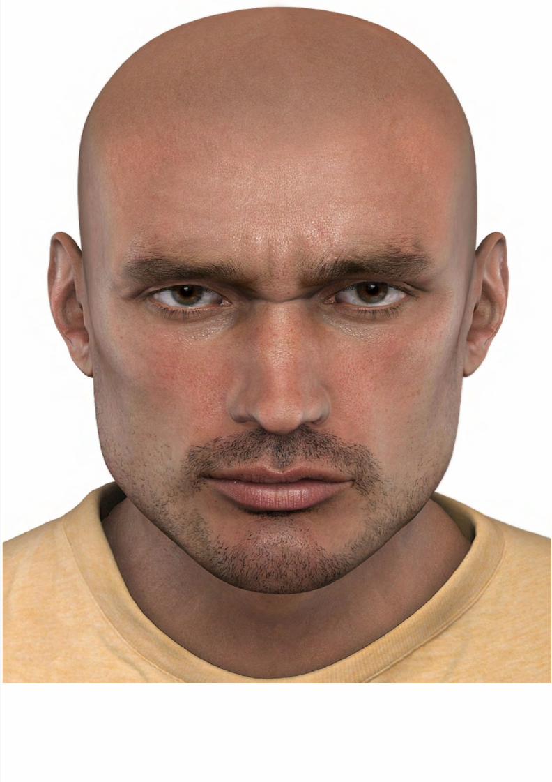
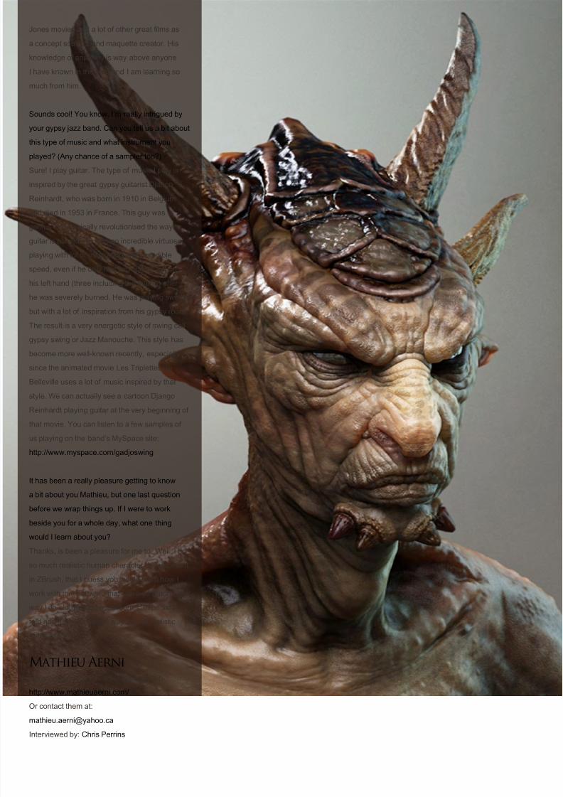
Thanks, is been a pleasure for me to. Well, I do
so much realistic human character development
in ZBrush, that I guess you would learn how I
work with that software that I love so much. The
way I do clothes and accessories, especially
fold and details, and the way I detail realistic
human faces.
Mathieu AerniFor more work by this artist, please visit:
http://www.mathieuaerni.com/
Or contact them at:
Interviewed by: Chris Perrins
8/10/2019 3DCreative Magazine Issue 033 May 2008
http://slidepdf.com/reader/full/3dcreative-magazine-issue-033-may-2008 15/224
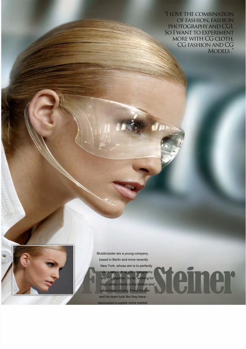
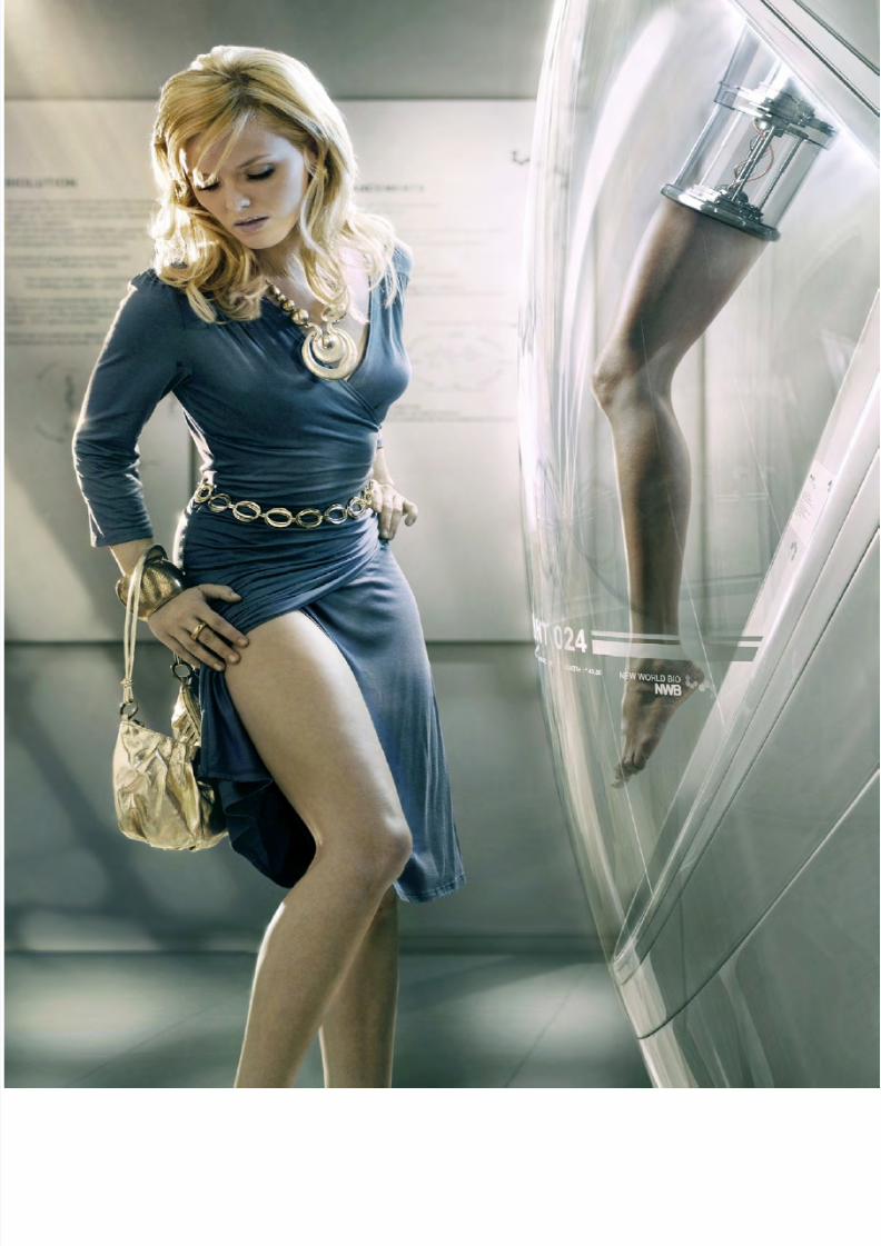
Blutsbrüeder are a young company,
based in Berlin and more recently
New York, whose aim is to perfectly
blend very high quality photography
and CG together. So far, working for
high caliber clients in the fashion and
advertising industry, Franz Steiner
and his team look like they have
discovered a superb niche market.
“I love the combinationof fashion, fashion
photography and CGI.So I want to experiment
more with CG cloth,CG fashion and CG
Models .”
8/10/2019 3DCreative Magazine Issue 033 May 2008
http://slidepdf.com/reader/full/3dcreative-magazine-issue-033-may-2008 16/224
page 18www.3dcreativemag.com Issue 033 May 2008
InterviewFranz Steiner
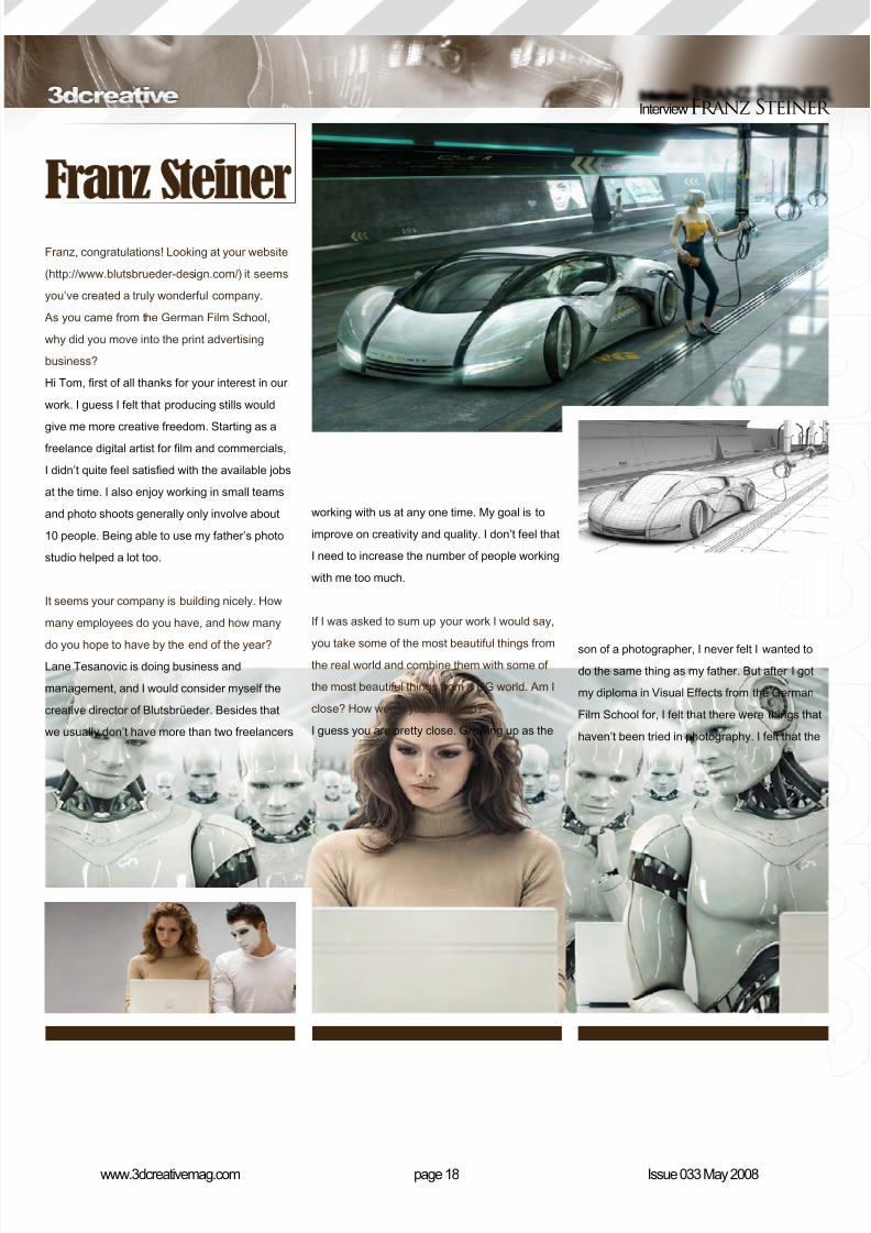
Franz, congratulations! Looking at your website
(http://www.blutsbrueder-design.com/) it seems
you’ve created a truly wonderful company.
As you came from the German Film School,
why did you move into the print advertising
business?
Hi Tom, rst of all thanks for your interest in our
work. I guess I felt that producing stills would
give me more creative freedom. Starting as afreelance digital artist for lm and commercials,
I didn’t quite feel satised with the available jobs
at the time. I also enjoy working in small teams
and photo shoots generally only involve about
10 people. Being able to use my father’s photo
studio helped a lot too.
It seems your company is building nicely. How
many employees do you have, and how many
do you hope to have by the end of the year?Lane Tesanovic is doing business and
management, and I would consider myself the
creative director of Blutsbrüeder. Besides that
we usually don’t have more than two freelancers
working with us at any one time. My goal is to
improve on creativity and quality. I don’t feel that
I need to increase the number of people working
with me too much.
If I was asked to sum up your work I would say,
you take some of the most beautiful things fromthe real world and combine them with some of
the most beautiful things from a CG world. Am I
close? How would you sum it up?
I guess you are pretty close. Growing up as the
son of a photographer, I never felt I wanted to
do the same thing as my father. But after I got
my diploma in Visual Effects from the German
Film School for, I felt that there were things that
haven’t been tried in photography. I felt that the
8/10/2019 3DCreative Magazine Issue 033 May 2008
http://slidepdf.com/reader/full/3dcreative-magazine-issue-033-may-2008 17/224
8/10/2019 3DCreative Magazine Issue 033 May 2008
http://slidepdf.com/reader/full/3dcreative-magazine-issue-033-may-2008 18/224
page 20www.3dcreativemag.com Issue 033 May 2008
InterviewFranz Steiner
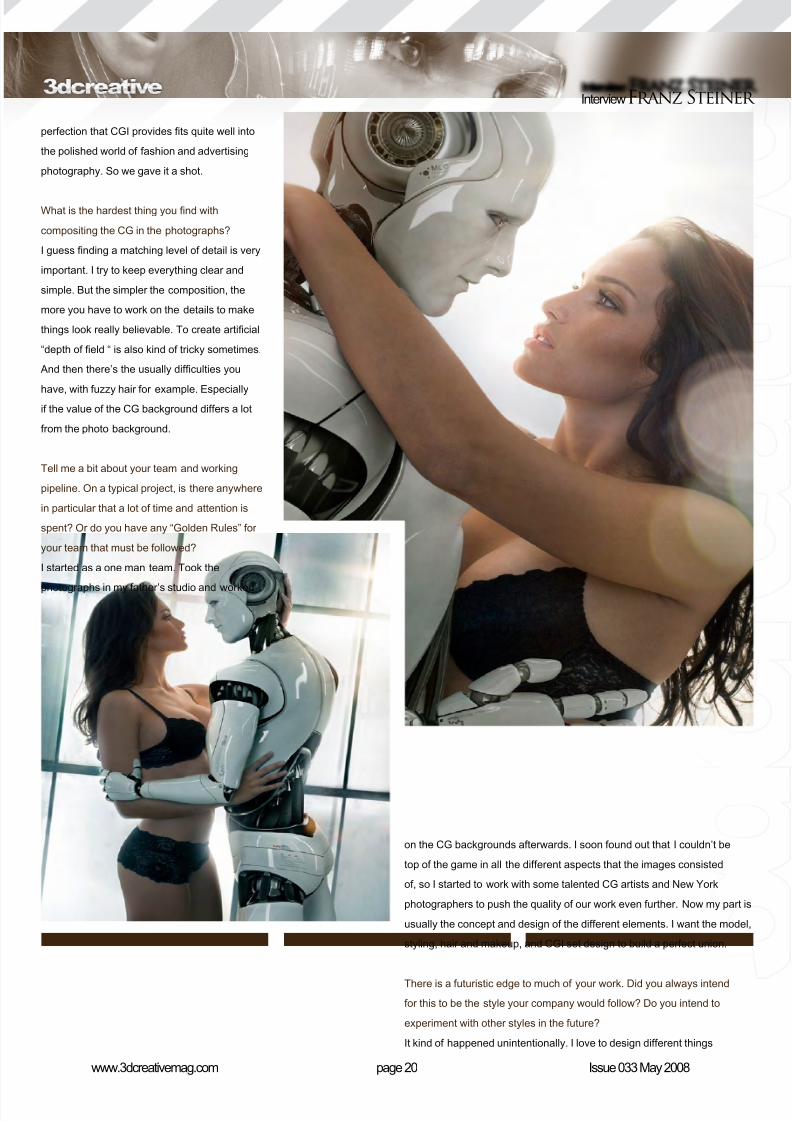
perfection that CGI provides ts quite well into
the polished world of fashion and advertising
photography. So we gave it a shot.
What is the hardest thing you nd with
compositing the CG in the photographs?
I guess nding a matching level of detail is very
important. I try to keep everything clear and
simple. But the simpler the composition, the
more you have to work on the details to make
things look really believable. To create articial
“depth of eld “ is also kind of tricky sometimes.
And then there’s the usually difculties you
have, with fuzzy hair for example. Especiallyif the value of the CG background differs a lot
from the photo background.
Tell me a bit about your team and working
pipeline. On a typical project, is there anywhere
in particular that a lot of time and attention is
spent? Or do you have any “Golden Rules” for
your team that must be followed?
I started as a one man team. Took the
photographs in my father’s studio and worked
on the CG backgrounds afterwards. I soon found out that I couldn’t be
top of the game in all the different aspects that the images consisted
of, so I started to work with some talented CG artists and New York
photographers to push the quality of our work even further. Now my part is
usually the concept and design of the different elements. I want the model,
styling, hair and makeup, and CGI set design to build a perfect union.
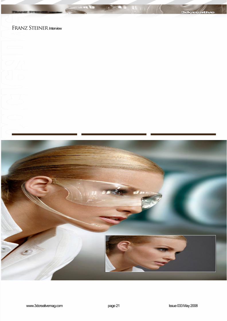
There is a futuristic edge to much of your work. Did you always intend
for this to be the style your company would follow? Do you intend to
experiment with other styles in the future?
It kind of happened unintentionally. I love to design different things
8/10/2019 3DCreative Magazine Issue 033 May 2008
http://slidepdf.com/reader/full/3dcreative-magazine-issue-033-may-2008 19/224
page 21www.3dcreativemag.com Issue 033 May 2008
Franz Steiner Interview
8/10/2019 3DCreative Magazine Issue 033 May 2008
http://slidepdf.com/reader/full/3dcreative-magazine-issue-033-may-2008 20/224
like technical gadgets and interiors. With
Blutsbrüeder I have the chance to step into the
position of a product designer, architect and
sometimes a photographer.
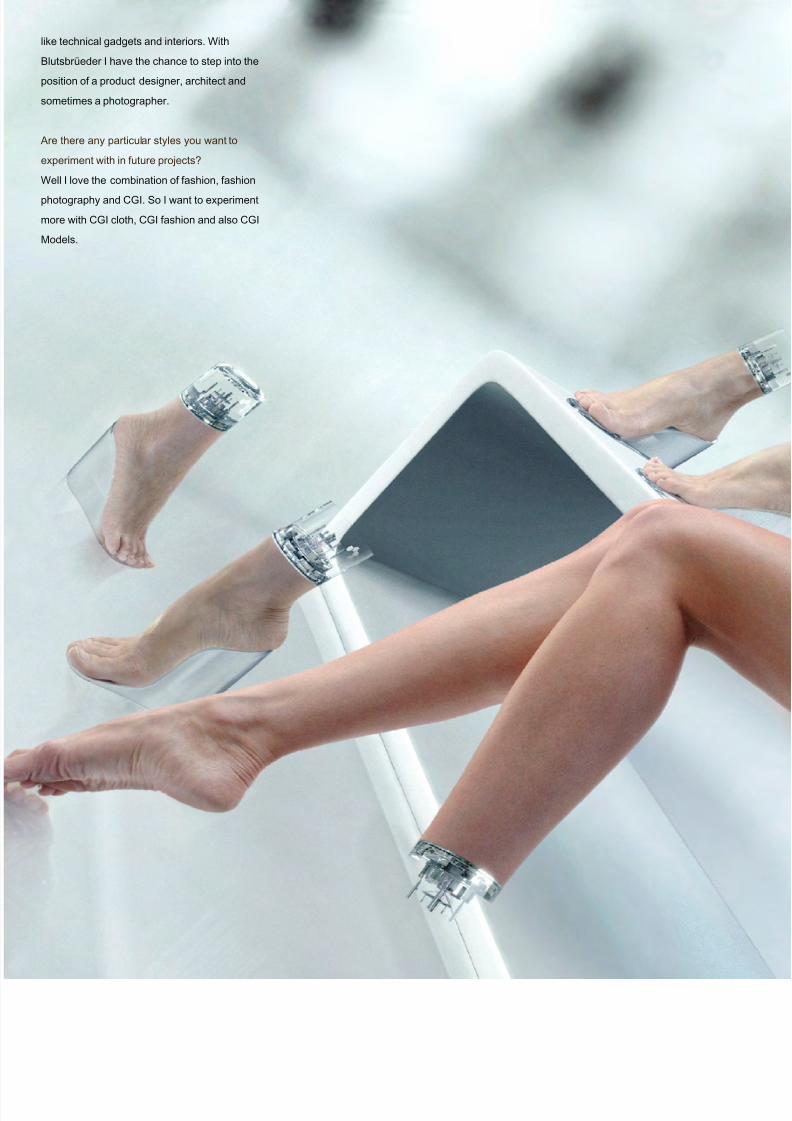
Are there any particular styles you want to
experiment with in future projects?
Well I love the combination of fashion, fashion
photography and CGI. So I want to experiment
more with CGI cloth, CGI fashion and also CGI
Models.
8/10/2019 3DCreative Magazine Issue 033 May 2008
http://slidepdf.com/reader/full/3dcreative-magazine-issue-033-may-2008 21/224

8/10/2019 3DCreative Magazine Issue 033 May 2008
http://slidepdf.com/reader/full/3dcreative-magazine-issue-033-may-2008 22/224
page 24www.3dcreativemag.com Issue 033 May 2008
InterviewFranz Steiner
What prompted the new ofce in New York?
For me it was kind of a logical step. I’m always
trying to improve the quality of our work, so I
simply wanted to be surrounded by people who
are on top of their game.
So how do you nd living and working in New
York compared with your home town?
It’s all about business over here. Which is why
I’m here, of course, but it can also be annoying
if its 24/7. Still I love the place and the people.
Everything seems very temporary. Which is
good because you get the chance to know
and do business with lots of different people,
but you don’t have the kind of relationships
where people have known each other since
kindergarten. So business-wise it’s good, but I
wouldn’t mind having some more of my buddies
around sometimes.
It must have been quite an exciting journey for
you since you established Blutsbrüeder in 2004.
What would you say have been the moments
that really stand out for you?
I guess the rst publication in a fashion
magazine was quite nice. And then the rst
big job for a named brand and a big German
Ad Agency, which helped us to establish the
business. And, of course, our rst ofce in NYC.
Also I think that nishing our Personal-Robot
story is a denite highlight because there’s not
much comparable material out there.
Can you give anything away regarding future
projects? What can we expect to see next?
Hopefully something you haven’t seen before.
Franz Steiner For more work by this artist please visit:
http://www.blutsbrueder-design.com/
Or contact them at:[email protected]
Interviewed by: Tom Greenway

8/10/2019 3DCreative Magazine Issue 033 May 2008
http://slidepdf.com/reader/full/3dcreative-magazine-issue-033-may-2008 23/224
Snickers ‘Robosoccer’,
‘Race’ and now ‘Rugby’,
these are the most
recongnisable commercialsfrom Unexpected. We chat
with the Alexander Kiesel,
head of VFX and Managing
Director of this amazing
studio.
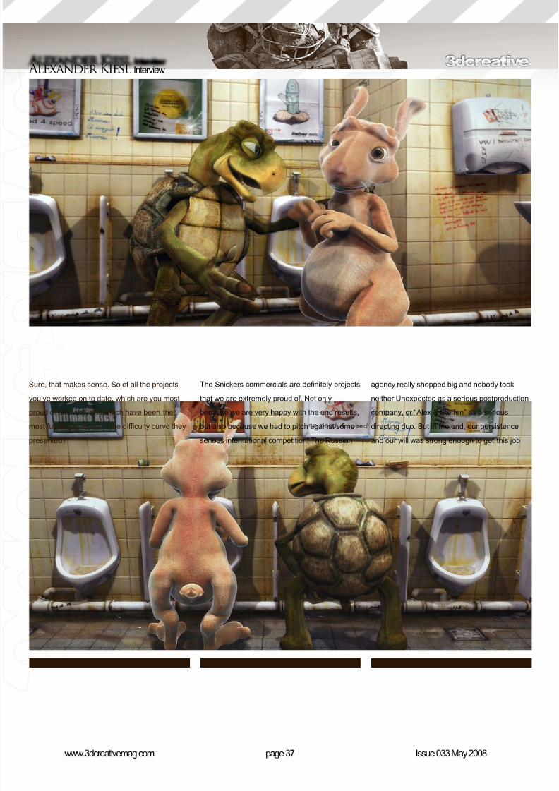
“The Snickerscommercials aredefinitely projectsthat we areextremely proud of.Not only because we
are very happy withthe end results, but
also because we hadto pitch againstsome seriousinternationalcompetition! ”
8/10/2019 3DCreative Magazine Issue 033 May 2008
http://slidepdf.com/reader/full/3dcreative-magazine-issue-033-may-2008 24/224
page 28www.3dcreativemag.com Issue 033 May 2008
Interview Alexander Kiesl
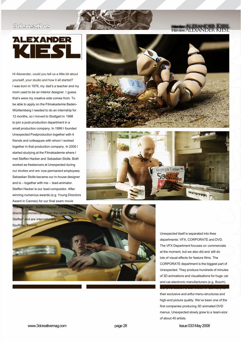
Hi Alexander, could you tell us a little bit about
yourself, your studio and how it all started?
I was born in 1976, my dad’s a teacher and my
mom used to be an interior designer. I guess
that’s were my creative side comes from. To
be able to apply on the Filmakademie Baden-
Württemberg I needed to do an internship for
12 months, so I moved to Stuttgart in 1998
to join a post-production department in a
small production company. In 1999 I founded
Unexpected Postproduction together with 4
friends and colleagues with whom I worked
together in that production company. In 2000 I
started studying at the Filmakademie where I
met Steffen Hacker and Sebastian Stolle. Both
worked as freelancers at Unexpected during
our studies and are now permanent employees.
Sebastian Stolle became our in-house designer
and is – together with me – lead-animator.
Steffen Hacker is our lead-compositor. After
winning numerous awards (e.g. Young Directors
Award in Cannes) for our nal exam movie
“Racing Beats”, Steffen Hacker and I started
directing commercials under the name “Alex &
Steffen” and are internationally represented by
Spylms, Toronto.
Unexpected itself is separated into thee
departments: VFX, CORPORATE and DVD.
The VFX Department focuses on commercials
at the moment, but we also did and still do
lots of visual effects for feature lms. The
CORPORATE department is the biggest part of
Unexpected. They produce hundreds of minutes
of 3D animations and visualisations for huge car
and car-electronic manufacturers (e.g. Bosch).
Our DVD section is well-known in Germany for
their exclusive and artful menu-structures and
high-end picture quality. We’ve been one of the
rst companies producing 3D animated DVD
menus. Unexpected slowly grew to a team-size
of about 40 artists.

8/10/2019 3DCreative Magazine Issue 033 May 2008
http://slidepdf.com/reader/full/3dcreative-magazine-issue-033-may-2008 25/224
page 29www.3dcreativemag.com Issue 033 May 2008
Alexander Kiesl Interview
You have a very impressive portfolio, but what
sticks out, to me, is your visual effects section.
Would you say this is the one area that your feel
your studio excels?
I would not say that the VFX department excels
the rest of the departments but it catches more
very creative in how we approach visual effect
shots and how we solve problems and tasks.
Instead of modelling and creating complex 3D
environments for one shot we rather think about
solutions that will end up in the same result but
with less effort. It’s a time saver and so you
attention as we are lucky to work on projects
which are very special and more popular…
Well… I guess that’s the main purpose of
commercials! Compared to other postproduction
houses we might have a very special kind of
philosophy for working on projects. We are
8/10/2019 3DCreative Magazine Issue 033 May 2008
http://slidepdf.com/reader/full/3dcreative-magazine-issue-033-may-2008 26/224
page 30www.3dcreativemag.com Issue 033 May 2008
Interview Alexander Kiesl
have more time for tweaking shots at the end, a
little bit more. As long as you don’t see it in the
end result it’s a good way to go. Who needs, for
example, a complex scenario which works fromevery perspective if you see it only in one shot
and from one direction?
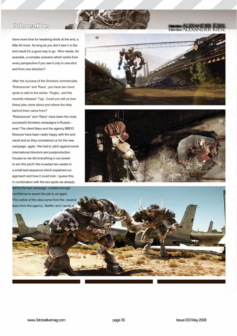
After the success of the Snickers commercials,
‘Robosoccer’ and ‘Race’, you have two more
spots to add to the series: ‘Rugby’, and the
recently released ‘Tag’. Could you tell us how
these jobs came about and where the idea
behind them came from?
“Robosoccer” and “Race” have been the mostsuccessful Snickers campaigns in Russia –
ever! The client Mars and the agency BBDO
Moscow have been really happy with the end
result and so they considered us for the new
campaign, again. We had to pitch against some
international directors and postproduction
houses so we did everything in our power
to win this pitch! We invested two weeks in
a small test-sequence which explained our
approach and how it could look. I guess this,in combination with the two spots we already
did for the last campaign, created enough
condence to award the job to us again.
The outline of the idea came from the creative
team from the agency. Steffen and I wrote a
8/10/2019 3DCreative Magazine Issue 033 May 2008
http://slidepdf.com/reader/full/3dcreative-magazine-issue-033-may-2008 27/224
page 31www.3dcreativemag.com Issue 033 May 2008
Alexander Kiesl Interview
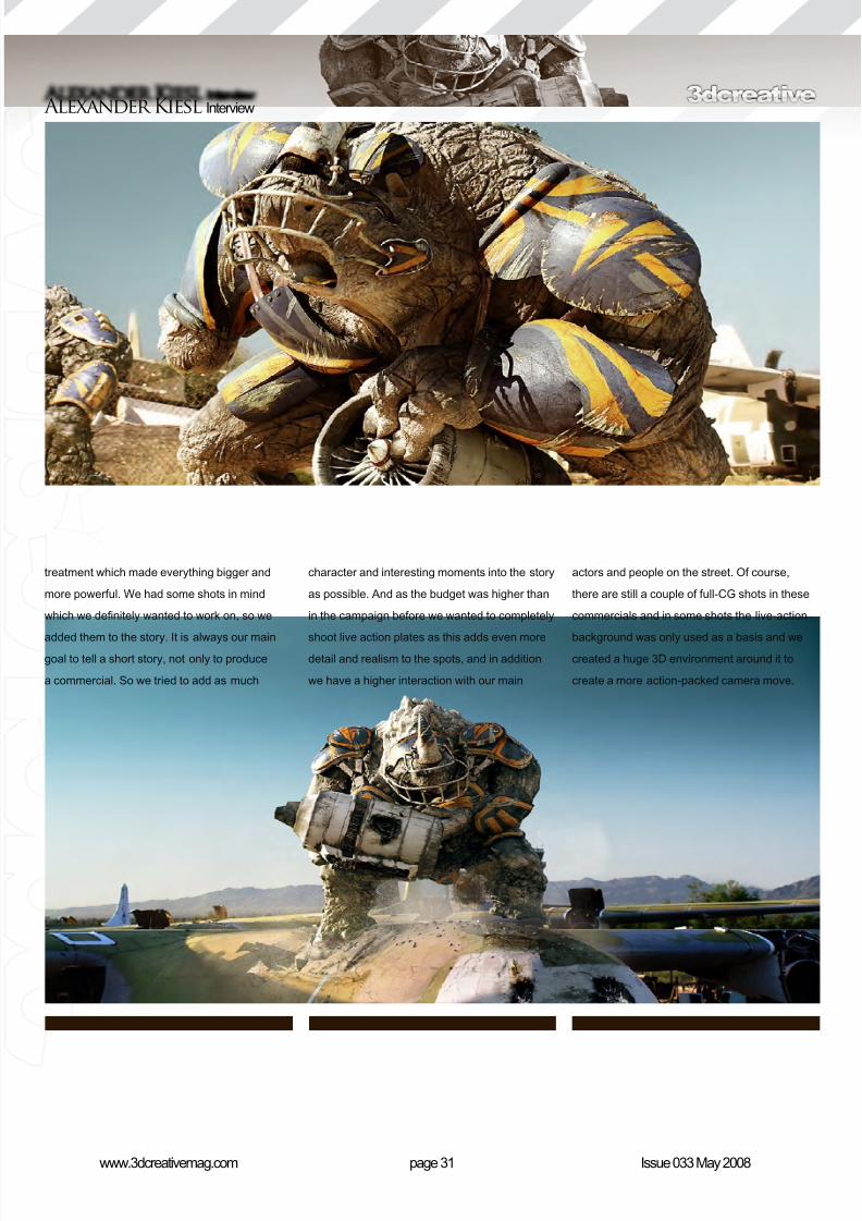
character and interesting moments into the story
as possible. And as the budget was higher than
in the campaign before we wanted to completely
shoot live action plates as this adds even moredetail and realism to the spots, and in addition
we have a higher interaction with our main
treatment which made everything bigger and
more powerful. We had some shots in mind
which we denitely wanted to work on, so we
added them to the story. It is always our maingoal to tell a short story, not only to produce
a commercial. So we tried to add as much
actors and people on the street. Of course,
there are still a couple of full-CG shots in these
commercials and in some shots the live-action
background was only used as a basis and wecreated a huge 3D environment around it to
create a more action-packed camera move.
8/10/2019 3DCreative Magazine Issue 033 May 2008
http://slidepdf.com/reader/full/3dcreative-magazine-issue-033-may-2008 28/224
page 32www.3dcreativemag.com Issue 033 May 2008
Interview Alexander Kiesl
How long would a project like this take to do?
We roughly work between 2 and 3 months
on each commercial. But this time includes
all the preparation for the shoot and thedevelopment and creation of the characters.
The postproduction alone took not more than 5
to 6 weeks!
To take that last question a little further, can
you give our readers some notion of the “turn
around” time for your various projects and the
kinds of deadlines you face on a regular basis?
A regular pitch for a commercial takes about 2
to 3 weeks. Depending on how many treatmentrevisions have to be written and how many tests
we allow ourselves to present to the agency, it
may be even a little bit longer. This all happens
parallel to the regular work. From the time
the job was awarded, to the rst meeting with
the production company, the agency and the
client, there are roughly two more weeks for
preparations. After the shoot we normally have
somewhere between one and two months for
the whole postproduction with numerous smallapprovals in between. As we are involved in
the planning from the very beginning we have a
certain amount of inuence on the schedule but
not on the deadline, of course. But it happened
that the original agency schedule reserved too
much time for the postproduction and so we
shortened it by a couple of weeks and brought
forward the deadline to have more time for
projects that come afterwards.
So what have been the most memorable and
the most stressful projects to date that your
studio has worked on?
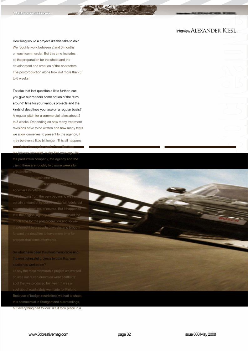
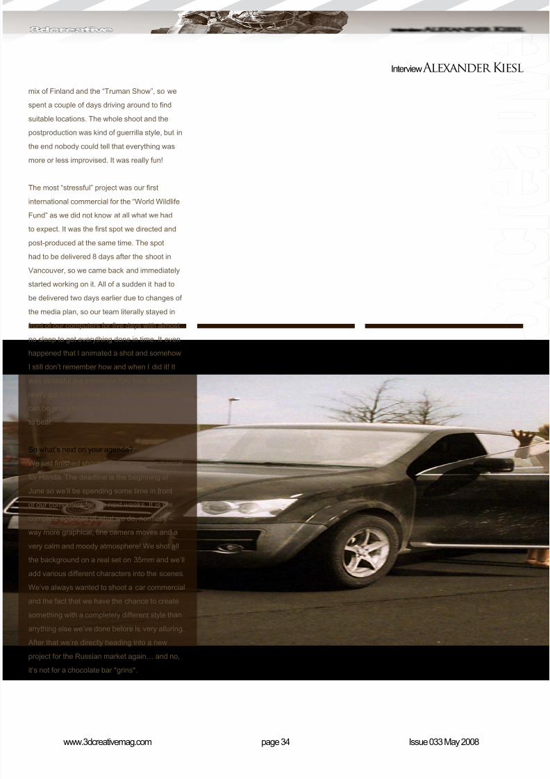
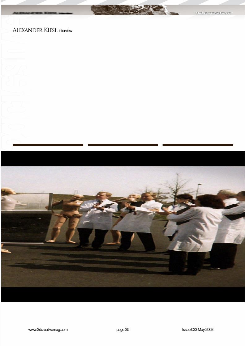
I’d say the most memorable project we worked
on was our “Even dummies wear seatbelts”
spot that we produced last year. It was a
spot about road safety we made for Finland.
Because of budget restrictions we had to shoot
this commercial in Stuttgart and surroundings,
but everything had to look like it took place in a

8/10/2019 3DCreative Magazine Issue 033 May 2008
http://slidepdf.com/reader/full/3dcreative-magazine-issue-033-may-2008 29/224
page 33www.3dcreativemag.com Issue 033 May 2008
Alexander Kiesl Interview
8/10/2019 3DCreative Magazine Issue 033 May 2008
http://slidepdf.com/reader/full/3dcreative-magazine-issue-033-may-2008 30/224
page 34www.3dcreativemag.com Issue 033 May 2008
Interview Alexander Kiesl
mix of Finland and the “Truman Show”, so we
spent a couple of days driving around to nd
suitable locations. The whole shoot and the
postproduction was kind of guerrilla style, but inthe end nobody could tell that everything was
more or less improvised. It was really fun!
The most “stressful” project was our rst
international commercial for the “World Wildlife
Fund” as we did not know at all what we had
to expect. It was the rst spot we directed and
post-produced at the same time. The spot
had to be delivered 8 days after the shoot in
Vancouver, so we came back and immediatelystarted working on it. All of a sudden it had to
be delivered two days earlier due to changes of
the media plan, so our team literally stayed in
front of our computers for ve days with almost
no sleep to get everything done in time. It even
happened that I animated a shot and somehow
I still don’t remember how and when I did it! It
was stressful but somehow fun, too. And we
really got to know how fast the commercial world
can be and what kind of pressure our team hasto bear.
So what’s next on your agenda?
We just nished shooting a new car commercial
for Honda. The deadline is the beginning of
June so we’ll be spending some time in front
of our computers for the next weeks. It is the
complete opposite of what we do, normally –
way more graphical, ne camera moves and a
very calm and moody atmosphere! We shot all
the background on a real set on 35mm and we’ll
add various different characters into the scenes.
We’ve always wanted to shoot a car commercial
and the fact that we have the chance to create
something with a completely different style than
anything else we’ve done before is very alluring.
After that we’re directly heading into a new
project for the Russian market again… and no,
it’s not for a chocolate bar *grins*.
8/10/2019 3DCreative Magazine Issue 033 May 2008
http://slidepdf.com/reader/full/3dcreative-magazine-issue-033-may-2008 31/224
page 35www.3dcreativemag.com Issue 033 May 2008
Alexander Kiesl Interview
8/10/2019 3DCreative Magazine Issue 033 May 2008
http://slidepdf.com/reader/full/3dcreative-magazine-issue-033-may-2008 32/224
page 36www.3dcreativemag.com Issue 033 May 2008
Interview Alexander Kiesl
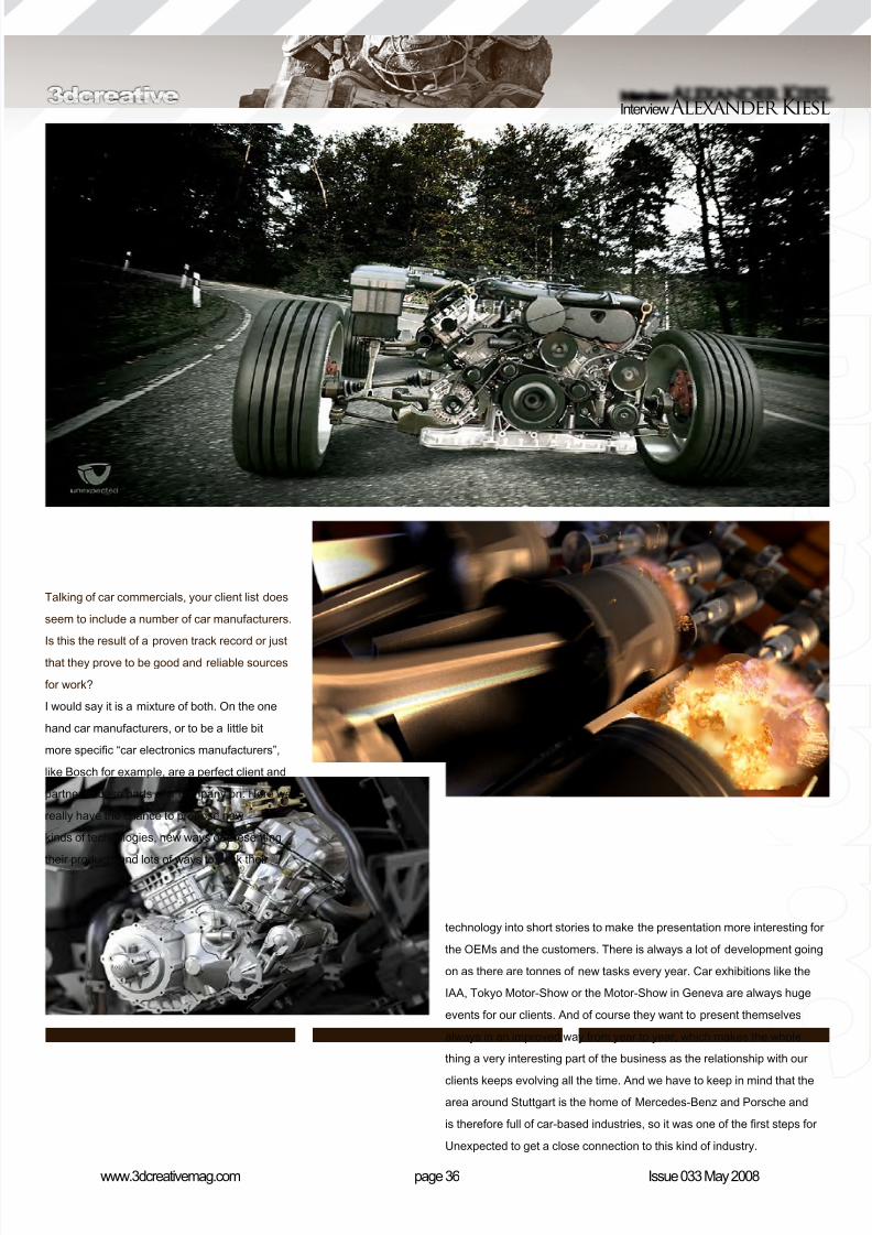
Talking of car commercials, your client list does
seem to include a number of car manufacturers.
Is this the result of a proven track record or just
that they prove to be good and reliable sources
for work?
I would say it is a mixture of both. On the one
hand car manufacturers, or to be a little bit
more specic “car electronics manufacturers”,
like Bosch for example, are a perfect client and
partner to base parts of a company on. Here we
really have the chance to propose new
kinds of technologies, new ways of presenting
their products and lots of ways to pack their
technology into short stories to make the presentation more interesting for
the OEMs and the customers. There is always a lot of development going
on as there are tonnes of new tasks every year. Car exhibitions like the
IAA, Tokyo Motor-Show or the Motor-Show in Geneva are always huge
events for our clients. And of course they want to present themselves
always in an improved way from year to year, which makes the whole
thing a very interesting part of the business as the relationship with our
clients keeps evolving all the time. And we have to keep in mind that the
area around Stuttgart is the home of Mercedes-Benz and Porsche and
is therefore full of car-based industries, so it was one of the rst steps for
Unexpected to get a close connection to this kind of industry.
8/10/2019 3DCreative Magazine Issue 033 May 2008
http://slidepdf.com/reader/full/3dcreative-magazine-issue-033-may-2008 33/224
page 37www.3dcreativemag.com Issue 033 May 2008
Alexander Kiesl Interview
Sure, that makes sense. So of all the projects
you’ve worked on to date, which are you most
proud of and why, and which have been themost fullling in terms of the difculty curve they
presented?
The Snickers commercials are denitely projects
that we are extremely proud of. Not only
because we are very happy with the end results,but also because we had to pitch against some
serious international competition! The Russian
agency really shopped big and nobody took
neither Unexpected as a serious postproduction
company, or “Alex & Steffen” as a seriousdirecting duo. But in the end, our persistence
and our will was strong enough to get this job
8/10/2019 3DCreative Magazine Issue 033 May 2008
http://slidepdf.com/reader/full/3dcreative-magazine-issue-033-may-2008 34/224
page 38www.3dcreativemag.com Issue 033 May 2008
Interview Alexander Kiesl
and to get it done in exactly the way we wanted
it. Of course, these spots were very demanding
and difcult and the expectations have been
very high on both the clients and our side, butthis pushed us even more.
What are the main drawbacks with offering
such a variety of services and skill sets across a
number of industry sectors, and do you require
multi-skilled staff as a result?
We always wanted to be based in more than
one sector. Each sector is based on the
motivation and the enthusiasm of one or two of
the ve managing partners/directors. Everybodywas able to choose the eld of business he
thought was worth working in. This way we
make sure the motivation is kept on a high level
as everybody has the freedom of developing
and shaping each department the way he wants
it. So we have three specialised sectors in one
company with a certain amount of overlapping
competences. I think you have to enjoy what
you’re doing as this is the biggest motivation
one can have to run a business. Somehow itfeels like we’ve all turned our hobbies into our
jobs, and this also applies for our artists.
We have lots of specialised artists, but the
biggest part of our staff is multi skilled. Of
course, we separate in 2D and 3D pools.
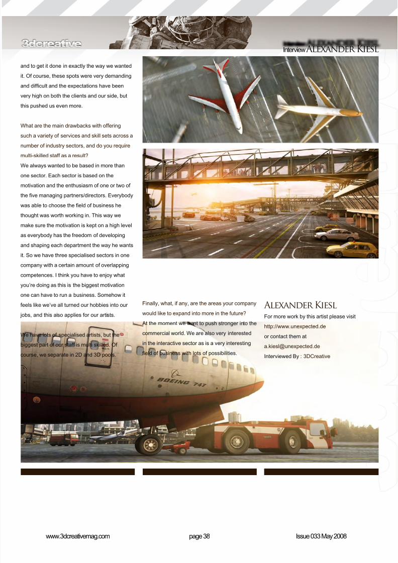
Finally, what, if any, are the areas your company
would like to expand into more in the future?
At the moment we want to push stronger into the
commercial world. We are also very interested
in the interactive sector as is a very interesting
eld of business with lots of possibilities.
Alexander KieslFor more work by this artist please visit
http://www.unexpected.de
or contact them at
Interviewed By : 3DCreative

8/10/2019 3DCreative Magazine Issue 033 May 2008
http://slidepdf.com/reader/full/3dcreative-magazine-issue-033-may-2008 35/224
“It’s better to masterone thing and
reach perfection init, because nobody
can be perfect at all things.”
This month, we have asked 3D artists from a
variety of backgrounds and locations
around the world:
Jack of all Trades
or Master of One?
Here’s what they said...
8/10/2019 3DCreative Magazine Issue 033 May 2008
http://slidepdf.com/reader/full/3dcreative-magazine-issue-033-may-2008 36/224
page 42www.3dcreativemag.com Issue 033 May 2008
Jack of all Trades or Master of One?
Ali IsmailDigital Artist, Lucaslm Animation, Singapore.
A freelancer should certainly be a jack of all
trades, but being part of a team in a big project
would require you to master one skill to the
fullest.
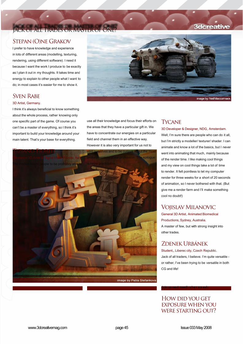
Anders Lejczak Project Manager, Framfab, Malmoe, Sweden.
Depends on your role within a project. Theproject manager should be more of an all round
person, but the project members should have
one or two elds of expertise.
André Holzmeister I believe it is best to learn everything and
master one particular trade. I can do modelling,
lighting, shading, rigging, render and working for
mastering my animation skills.
Andre Kutscherauer 3D Designer, Studio Messslinger Gmbh,
Munich, Germany.
Lighting, rendering and composition.
BogdanYou have to know a little bit of everything and
master at least one.
Cesar Alejandro
Montero OrozcoCG Artist & Freelancer, Digi-Guys, London, UK
& Mexico.
Jack of all trades, and hoping to be a master of
lighting.
Dana DorianDirector, Axis Animation, Glasgow, Scotland, UK
I think it is better to be a master of one skill and
be good at any skills that support that master
skill. Like a master modeller should be good
at texturing. I feel this is better than being a
jack of all trades, because people who can do
everything are rarely the best at any of them.
Daniel VijoiI like to be able to experience as many different
elds as I can. From 2D to 3D; traditional work
to concept art and design etc - it’s awesome
to be able to work with different programs and
techniques and then combine them to make in
the end a masterpiece. But I think if one wants
to work in a particular area then it’s better to
focus on excelling in that particular eld.
Eric Provan3D Modeller, Sony Pictures Imageworks, LA,
USA.
In my opinion, my strongest skill is modelling.
It’s what I’ve focused on the most. However, I
do strive to be a jack of all trades because I feel
that understanding all the aspects of CG will
only make me a better modeller. My biggest foe
at the moment seems to be animating.
Eugenio Garcia3D Illustrator & Animator, GrupoW, Saltillo,
México.
Jack of all trades.
Gustavo GroppoGeneral 3D Artist, Mamute Mídia, São Paulo,
Brazil.
Artists with great effort should be the masters of
all the things they want.
Hasraf Dulull
Visual Effects Artist, The Moving Picture
Company, London Soho.
Some studios like jacks of all trades, but
if you go for bigger studios then they tend
to hire specialists such as lighters, riggers,
8/10/2019 3DCreative Magazine Issue 033 May 2008
http://slidepdf.com/reader/full/3dcreative-magazine-issue-033-may-2008 37/224
page 43www.3dcreativemag.com Issue 033 May 2008
Jack of all Trades or Master of One?
compositors, match movers etc. I chose to
focus on compositing so that I could become
really good in that and then agencies and other
studios who wanted compositors would get meon their list.
Jure ZagoricnikWeb Developer & 3D Freelancer, Hal interactive
& 3D Graka, Kamnik, Slovenia.
I am trying to cover as many areas as possible.
Liam KempI’m really a bit of both, so I’d be lying if I said
either one.
Matt WestrupDepends what you enjoy doing. If you enjoy only
one aspect then become a master of it. There
isn’t any point in trying to be a jack of all trades
if you don’t enjoy the process.
Michael Seidl3D Artist, Modelling & Rendering,
www.michaelseidl.com, Vienna, Austria.Master of one, or maybe two. I have the most
fun by doing light setups and making all kind of
shaders. I can spend hours and hours thinking
about how to solve different light setups, or
making my own HDRI.
Neil MaccormackFreelance 3D artist, Bearfootlms, Geneva ,
Switzerland.
At the moment: jack of all trades.
Nicolas CollingsIt’s all depends on your objective. If you want to
work in big company, I’d denitely say “master
of one”. And if you want to work in a small or
medium company then “jack of all trades”.
Pedro MendezMaster of one. While it’s good to be able to work
in lots of different areas, you also need to dene
what you want to be recognised for.
8/10/2019 3DCreative Magazine Issue 033 May 2008
http://slidepdf.com/reader/full/3dcreative-magazine-issue-033-may-2008 38/224
page 44www.3dcreativemag.com Issue 033 May 2008
Jack of all Trades or Master of One?
Pete SussiDepends on why you’re doing it. Common logic
states that if you’re looking for a job in CG then
get good at one thing. If it’s for a more personal
reason, then try it all! There are a fair amount
of talented artists who are great at many things.
If we pigeon-holed artists into one thing ... then
there would have been no Michael Angelo!
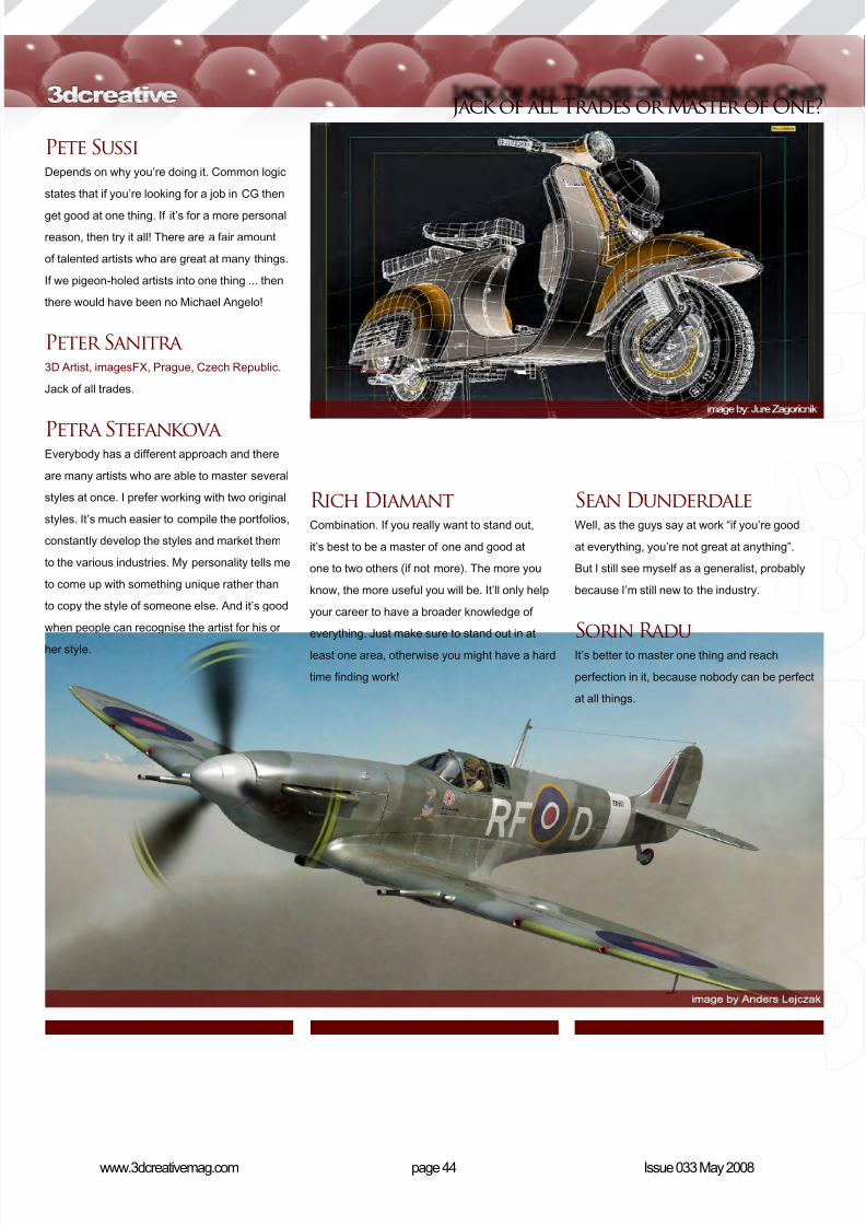
Peter Sanitra3D Artist, imagesFX, Prague, Czech Republic.
Jack of all trades.
Petra StefankovaEverybody has a different approach and there
are many artists who are able to master several
styles at once. I prefer working with two original
styles. It’s much easier to compile the portfolios,
constantly develop the styles and market them
to the various industries. My personality tells me
to come up with something unique rather than
to copy the style of someone else. And it’s good
when people can recognise the artist for his or
her style.
Rich DiamantCombination. If you really want to stand out,
it’s best to be a master of one and good at
one to two others (if not more). The more you
know, the more useful you will be. It’ll only help
your career to have a broader knowledge of
everything. Just make sure to stand out in at
least one area, otherwise you might have a hard
time nding work!
Sean Dunderdale
Well, as the guys say at work “if you’re good
at everything, you’re not great at anything”.
But I still see myself as a generalist, probably
because I’m still new to the industry.
Sorin RaduIt’s better to master one thing and reach
perfection in it, because nobody can be perfect
at all things.
8/10/2019 3DCreative Magazine Issue 033 May 2008
http://slidepdf.com/reader/full/3dcreative-magazine-issue-033-may-2008 39/224
page 45www.3dcreativemag.com Issue 033 May 2008
Jack of all Trades or Master of One?
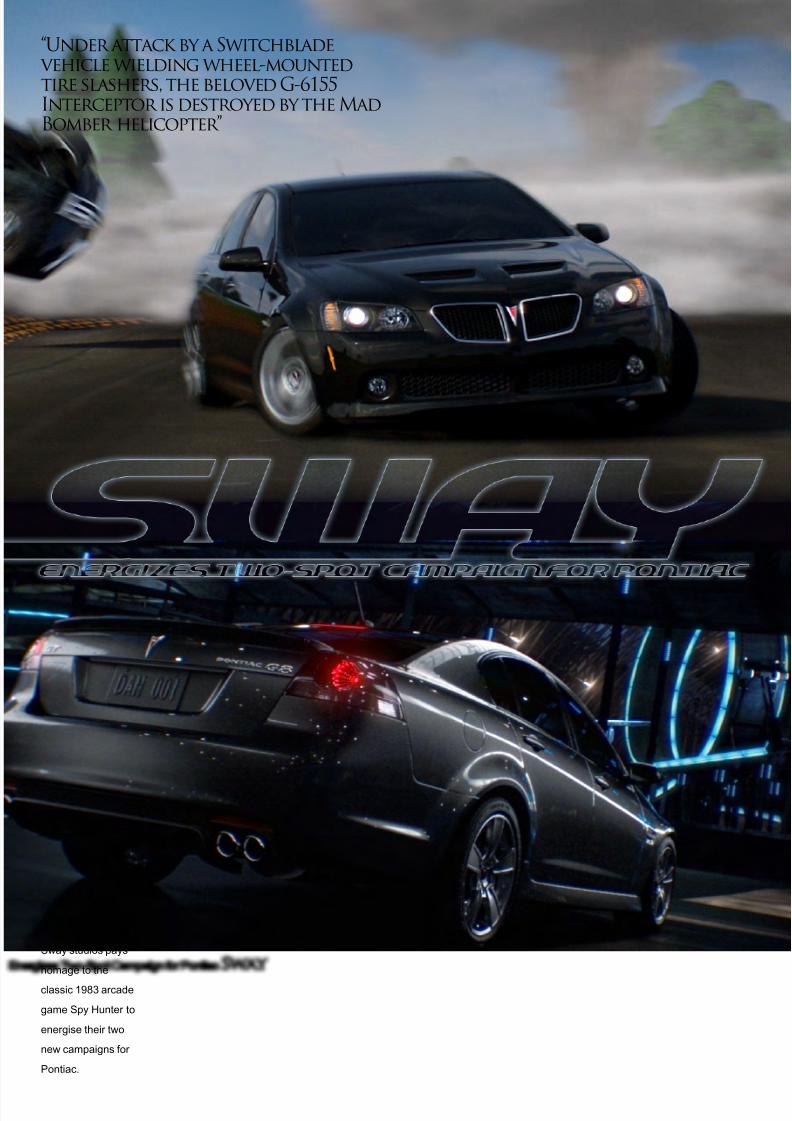
Stepan (O)ne Grakov I prefer to have knowledge and experience
in lots of different areas (modelling, texturing,
rendering, using different software). I need it
because I want the work I produce to be exactly
as I plan it out in my thoughts. It takes time and
energy to explain to other people what I want to
do; in most cases it’s easier for me to show it.
Sven Rabe
3D Artist, Germany.
I think it’s always benecial to know something
about the whole process, rather knowing only
one specic part of the game. Of course you
can’t be a master of everything, so I think it’s
important to build your knowledge around your
main talent. That’s your base for everything.
Tiziano FioritiFreelance 3D Artist & Digital Matte Painter, Italy.
The market needs people to be protably able to
use all their knowledge and focus their efforts on
the areas that they have a particular gift in. We
have to concentrate our energies on a particular
eld and channel them in an effective way.
However it is also very important for us not to
stint ourselves and to be curious about the most
unlikely aspects of our profession. The epilogue
is never predictable.
Tycane3D Developer & Designer, NDG, Amsterdam.
Well, I’m sure there are people who can do it all,
but I’m strictly a modeller/ texturer/ shader. I can
animate and know a lot of the basics, but I never
went into animating that much, mainly because
of the render time. I like making cool things
and my view on cool things take a lot of time
to render. It felt pointless to let my computer
render for three weeks for a short of 20 seconds
of animation, so I never bothered with that. (But
give me a render farm and I’ll make something
cool no doubt!)
Vojislav MilanovicGeneral 3D Artist, Animated Biomedical
Productions, Sydney, Australia.
A master of few, but with strong insight into
other trades.
Zdenek Urbánek Student,, Liberec city, Czech Republic.
Jack of all traders, I believe. I’m quite versatile -
or rather, I’ve been trying to be versatile in both
CG and life!
Join us next month when we ask:
How did you getexposure when you were starting out?
8/10/2019 3DCreative Magazine Issue 033 May 2008
http://slidepdf.com/reader/full/3dcreative-magazine-issue-033-may-2008 40/224
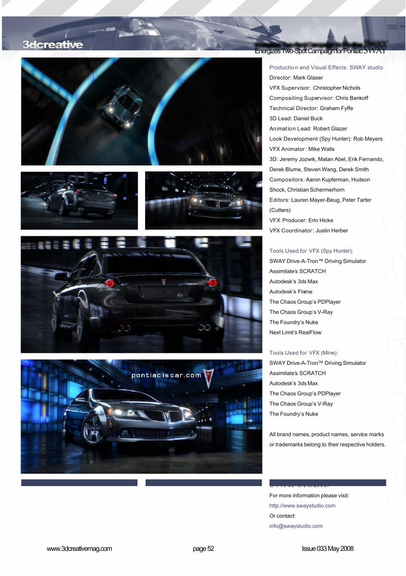
Energizes Two-Spot Campaign for PontiacSway
Sway studios pays
homage to the
classic 1983 arcade
game Spy Hunter to
energise their two
new campaigns for
Pontiac.
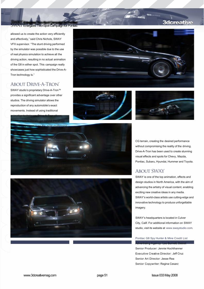
“Under attack by a Switchblade vehicle wielding wheel-mountedtire slashers, the beloved G-6155Interceptor is destroyed by the MadBomber helicopter”

8/10/2019 3DCreative Magazine Issue 033 May 2008
http://slidepdf.com/reader/full/3dcreative-magazine-issue-033-may-2008 41/224
page 49www.3dcreativemag.com Issue 033 May 2008
Sway Energizes Two-Spot Campaign for Pontiac
SWAY studio’s work on the new action-packed
campaign introducing the 2008 Pontiac G8
explodes from the screen with thrilling driving
action and great-looking CG environments.
Currently airing nationwide, Spy Hunter and
Mine, both 30 second spots for Leo Burnett,
Detroit, were created using SWAY’s renowned
photo-real lighting techniques, as well as its
secret weapon, the proprietary Drive-A-Tron™
driving simulator.
Spy Hunter An homage to the classic 1983 Bally Midway
arcade game, Spy Hunter opens with the
vintage graphics and addictive theme music that
captivated arcade fans over two decades ago.
Under attack by a Switchblade vehicle wielding
wheel-mounted tire slashers, the beloved
G-6155 Interceptor is destroyed by the Mad
Bomber helicopter. As the red truck pulls up to
replace the hero car, a seamlessly integrated
photo-real Pontiac G8 appears and races down
the ramp. Swerving around, dropping bombs
and out-maneuvering enemy cars, it quickly
leaves its nemeses in its dust.
“After carefully studying the intricacies of theoriginal game, it became imperative that we
created a fully 3D world respectful of the game’s
intense popularity,” said Mark Glaser, SWAY’s
creative director, who also directed the spots.
To showcase the superior performance of
the G8, SWAY introduced several “close
call” hazards, such as tight turns, a large
water puddle and a giant explosion. SWAY’s
proprietary Drive-A-Tron driving simulator,which allows for real-time, interactive, accurate
and realistic automobile animation, was even
programmed to include Pontiac’s StabiliTrack

8/10/2019 3DCreative Magazine Issue 033 May 2008
http://slidepdf.com/reader/full/3dcreative-magazine-issue-033-may-2008 42/224
page 50www.3dcreativemag.com Issue 033 May 2008
Energizes Two-Spot Campaign for PontiacSway
and anti-lock braking. This gave the CG G8
more traction control and quick stopping
capability.
MineMine showcases a beautiful virtual playground,
full of high-speed twists and turns. Sharp
gradients, incredible turns and a giant loop add
to the excitement of the life-size Hot Wheels
track.
For this spot, SWAY built a sleek and modern
environment in CG, where all components and
lighting features were designed to appear true toreal life, in an effort to create a believable event
spot. It takes place inside a giant blimp hangar,
which in reality would be the only location large
enough to house the construction of such a
track. Once the track was complete, SWAY
animators, as well as the agency, were able to
virtually perform all stunt driving using the Drive-
A-Tron simulator.
Realistically, Spy Hunter and Mine could onlyexist in fully CG worlds, yet it was important
that the G8 could perform precisely as the
actual car would. “The use of the Drive-A-Tron
8/10/2019 3DCreative Magazine Issue 033 May 2008
http://slidepdf.com/reader/full/3dcreative-magazine-issue-033-may-2008 43/224
page 51www.3dcreativemag.com Issue 033 May 2008
Sway Energizes Two-Spot Campaign for Pontiac
allowed us to create the action very efciently
and effectively,” said Chris Nichols, SWAY
VFX supervisor. “The stunt driving performed
by the simulator was possible due to the useof real physics simulation to achieve all the
driving action, resulting in no actual animation
of the G8 in either spot. This campaign really
showcases just how sophisticated the Drive-A-
Tron technology is.”
About Drive-A-Tron™SWAY studio’s proprietary Drive-A-Tron™
provides a signicant advantage over other
studios. The driving simulator allows thereproduction of any automobile’s exact
movements. Instead of using traditional
animation techniques, Drive-A-Tron allows
SWAY artists to literally get behind the wheel
and drive the car on even the most challenging
CG terrain, creating the desired performance
without compromising the reality of the driving.
Drive-A-Tron has been used to create stunningvisual effects and spots for Chevy, Mazda,
Pontiac, Subaru, Hyundai, Hummer and Toyota.
About SWAYSWAY is one of the top animation, effects and
design studios in North America, with the aim of
advancing the artistry of visual content, enabling
exciting new creative ideas in any media.
SWAY’s world-class artists use cutting-edge and
innovative technology to produce unforgettable
imagery.
SWAY’s headquarters is located in Culver
City, Calif. For additional information on SWAY
studio, visit its website at www.swaystudio.com.
Pontiac G8 Spy Hunter & Mine Credit List
Advertising Agency: Leo Burnett, Detroit
Senior Producer: Jennie Hochthanner
Executive Creative Director: Jeff Cruz
Senior Art Director: Jesse Rea
Senior Copywriter: Regina Cesarz
8/10/2019 3DCreative Magazine Issue 033 May 2008
http://slidepdf.com/reader/full/3dcreative-magazine-issue-033-may-2008 44/224
page 52www.3dcreativemag.com Issue 033 May 2008
Energizes Two-Spot Campaign for PontiacSway
Production and Visual Effects: SWAY studio
Director: Mark Glaser
VFX Supervisor: Christopher Nichols
Compositing Supervisor: Chris Bankoff Technical Director: Graham Fyffe
3D Lead: Daniel Buck
Animat ion Lead: Robert Glazer
Look Development (Spy Hunter ): Rob Meyers
VFX Animator : Mike Walls
3D: Jeremy Jozwik, Matan Abel, Erik Fernando,
Derek Blume, Steven Wang, Derek Smith
Compositors: Aaron Kupferman, Hudson
Shock, Christian Schermerhorn
Editors: Lauren Mayer-Beug, Peter Tarter(Cutters)
VFX Producer: Erin Hicke
VFX Coordinator : Justin Herber
Tools Used for VFX (Spy Hunter ):
SWAY Drive-A-Tron™ Driving Simulator
Assimilate’s SCRATCH
Autodesk’s 3ds Max
Autodesk’s Flame
The Chaos Group’s PDPlayer The Chaos Group’s V-Ray
The Foundry’s Nuke
Next Limit’s RealFlow
Tools Used for VFX (Mine):
SWAY Drive-A-Tron™ Driving Simulator
Assimilate’s SCRATCH
Autodesk’s 3ds Max
The Chaos Group’s PDPlayer
The Chaos Group’s V-Ray
The Foundry’s Nuke
All brand names, product names, service marks
or trademarks belong to their respective holders.
SWAY studioFor more information please visit:
http://www.swaystudio.com
Or contact:
8/10/2019 3DCreative Magazine Issue 033 May 2008
http://slidepdf.com/reader/full/3dcreative-magazine-issue-033-may-2008 45/224
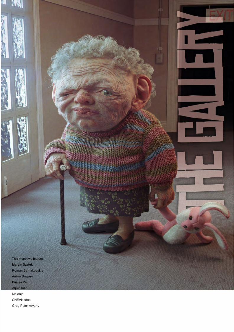
This month we feature:
Marcin Szałek
Roman Samakovskiy
Anton Bugaev
Pâşlea Paul
Alper Ki lic
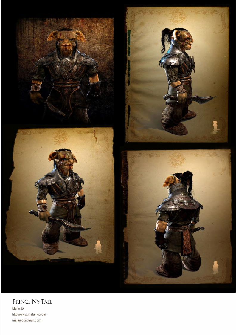
Malanjo
CHEVisodes
Greg Petchkovsky
8/10/2019 3DCreative Magazine Issue 033 May 2008
http://slidepdf.com/reader/full/3dcreative-magazine-issue-033-may-2008 46/224
page 56www.3dcreativemag.com Issue 033 May 2008
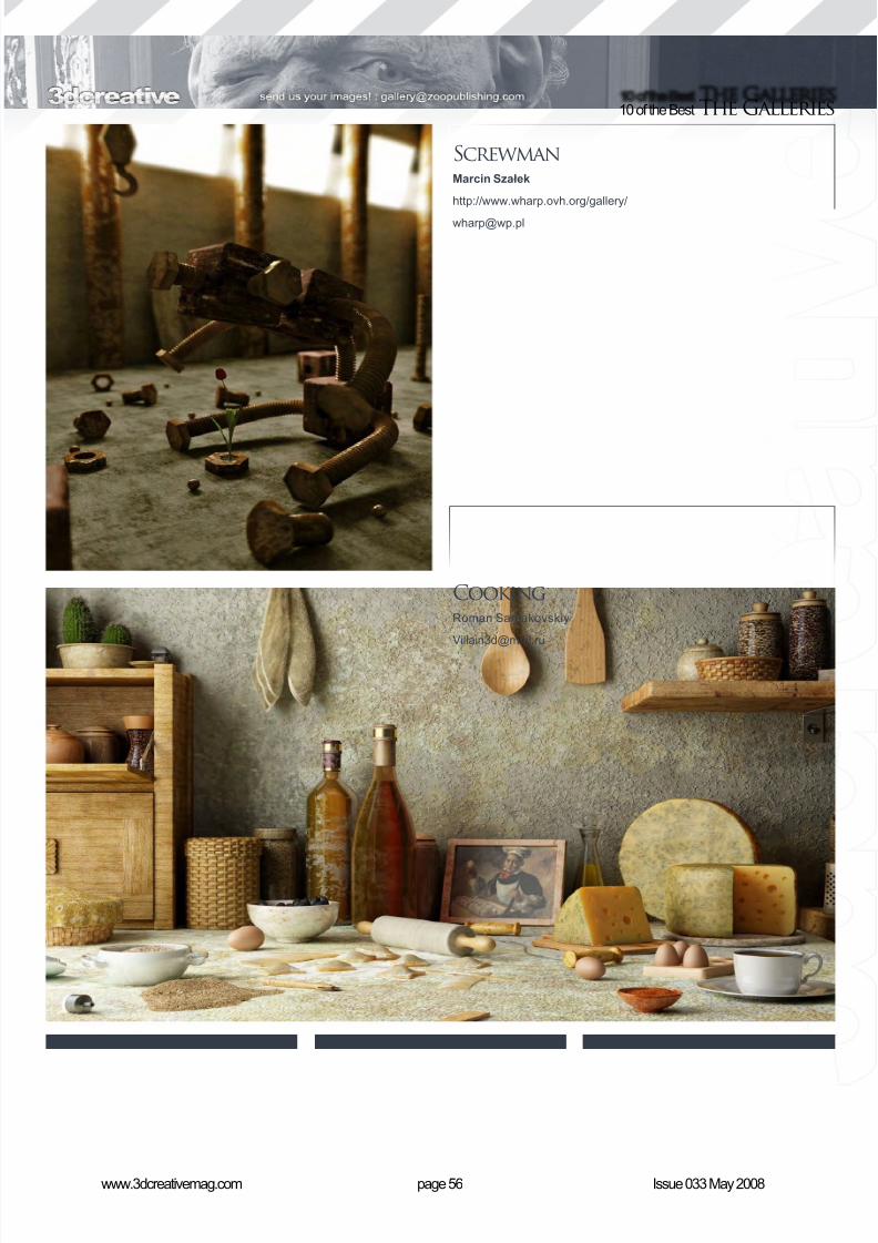
10 of the Best The Galleries
ScrewmanMarcin Szałek
http://www.wharp.ovh.org/gallery/
CookingRoman Samakovskiy
8/10/2019 3DCreative Magazine Issue 033 May 2008
http://slidepdf.com/reader/full/3dcreative-magazine-issue-033-may-2008 47/224
8/10/2019 3DCreative Magazine Issue 033 May 2008
http://slidepdf.com/reader/full/3dcreative-magazine-issue-033-may-2008 48/224
page 58www.3dcreativemag.com Issue 033 May 2008
10 of the Best The Galleries
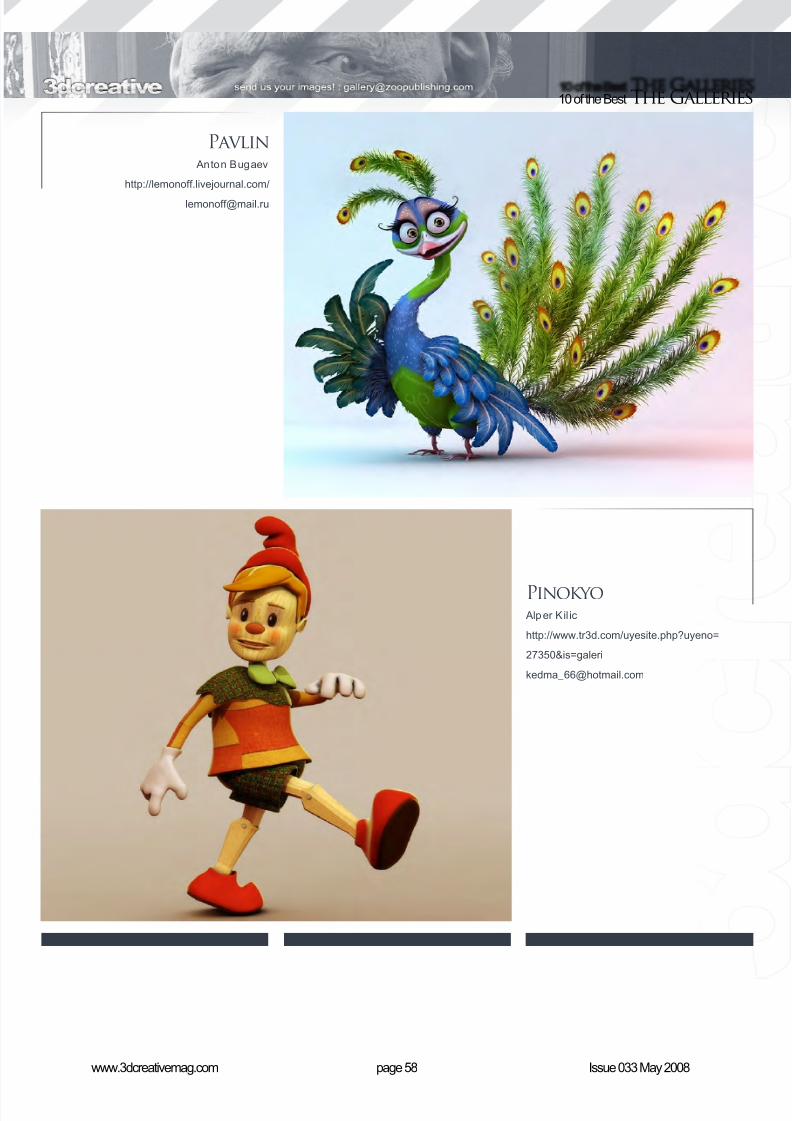
Pavlin Anton Bugaev
http://lemonoff.livejournal.com/
Pinokyo Alper Kil ic
http://www.tr3d.com/uyesite.php?uyeno=
27350&is=galeri
8/10/2019 3DCreative Magazine Issue 033 May 2008
http://slidepdf.com/reader/full/3dcreative-magazine-issue-033-may-2008 49/224
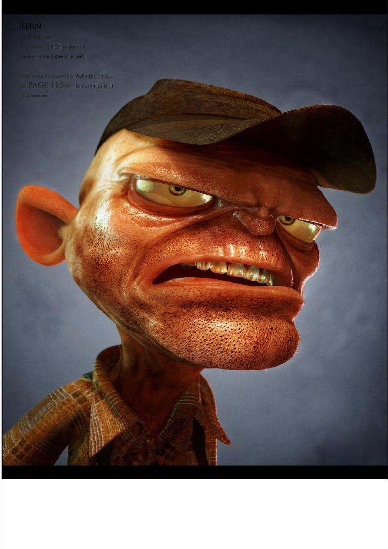
FernCHEVisodes
http://www.CHEVisodes.com
Don’t miss out on the Making Of ‘Fern’
on page 115 in this very issue of
3DCreative!
8/10/2019 3DCreative Magazine Issue 033 May 2008
http://slidepdf.com/reader/full/3dcreative-magazine-issue-033-may-2008 50/224
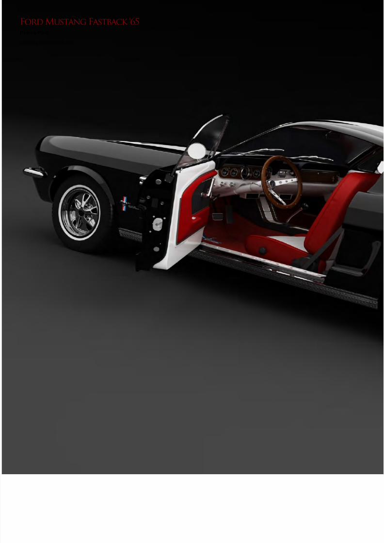
Ford Mustang Fastback ‘65Pâşlea Paul

8/10/2019 3DCreative Magazine Issue 033 May 2008
http://slidepdf.com/reader/full/3dcreative-magazine-issue-033-may-2008 51/224
8/10/2019 3DCreative Magazine Issue 033 May 2008
http://slidepdf.com/reader/full/3dcreative-magazine-issue-033-may-2008 52/224
page 62www.3dcreativemag.com Issue 033 May 2008
10 of the Best The Galleries
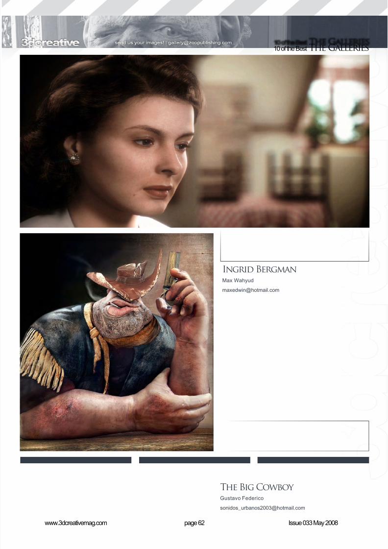
The Big Cowboy Gustavo Federico
Ingrid BergmanMax Wahyud
8/10/2019 3DCreative Magazine Issue 033 May 2008
http://slidepdf.com/reader/full/3dcreative-magazine-issue-033-may-2008 53/224
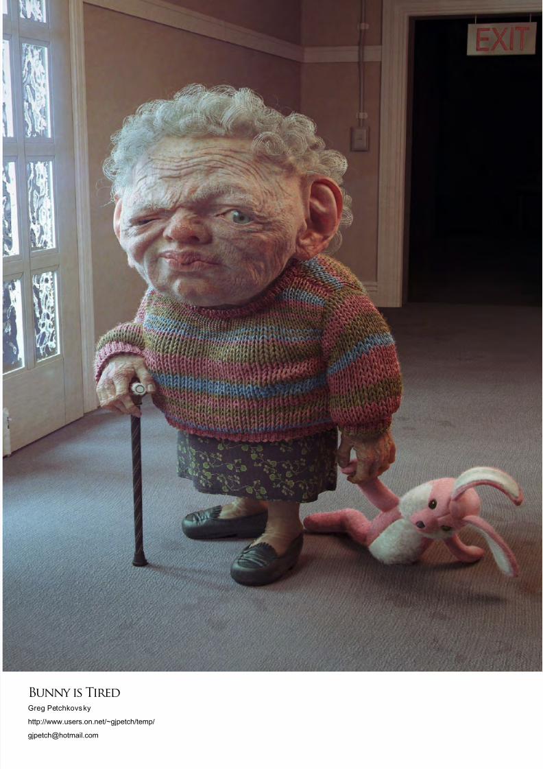
Bunny is TiredGreg Petchkovsky
http://www.users.on.net/~gjpetch/temp/

8/10/2019 3DCreative Magazine Issue 033 May 2008
http://slidepdf.com/reader/full/3dcreative-magazine-issue-033-may-2008 54/224
In Association with
3DCreative Magazine introduces the
‘Challenge’ section of the mag. Every
month we will run these challenges,
available for anyone to enter for prizes and
goodies from the www.3dtotal.com shop,
and also for the chance to be featured in
this very magazine! The 2D challenge
runs in the ConceptArt.org forums, and
the 3D challenge runs in the Threedy.com
forums. Here we will display the winners
from the previous month’s challenge, and
the “Making Of”s from the month before
that...
In Association with
Stylised Challenge
Executioner!
(c)istockphoto.com/Arkadiusz Fajer
8/10/2019 3DCreative Magazine Issue 033 May 2008
http://slidepdf.com/reader/full/3dcreative-magazine-issue-033-may-2008 55/224
page 66www.3dcreativemag.com Issue 033 May 2008
Stylised ChallengeExecutioner
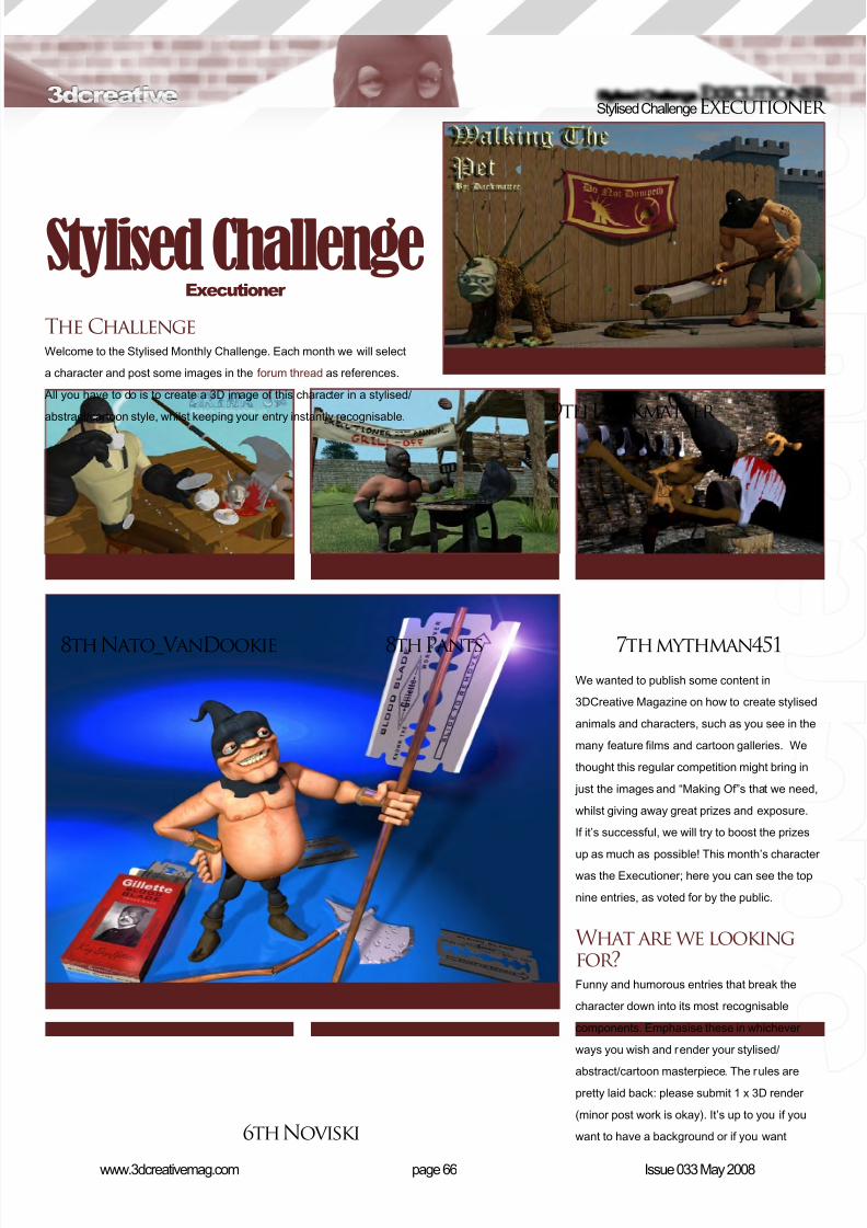
The ChallengeWelcome to the Stylised Monthly Challenge. Each month we will select
a character and post some images in the f orum thread as references.
All you have to do is to create a 3D image of this character in a stylised/
abstract/cartoon style, whilst keeping your entry instantly recognisable.
We wanted to publish some content in
3DCreative Magazine on how to create stylised
animals and characters, such as you see in the
many feature lms and cartoon galleries. We
thought this regular competition might bring in
just the images and “Making Of”s that we need,
whilst giving away great prizes and exposure.
If it’s successful, we will try to boost the prizes
up as much as possible! This month’s character
was the Executioner; here you can see the top
nine entries, as voted for by the public.
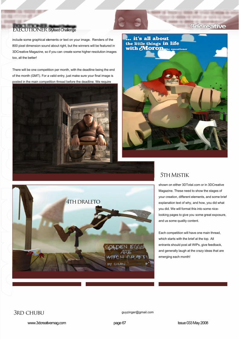
What are we lookingfor?Funny and humorous entries that break the
character down into its most recognisable
components. Emphasise these in whichever
ways you wish and render your stylised/
abstract/cartoon masterpiece. The rules arepretty laid back: please submit 1 x 3D render
(minor post work is okay). It’s up to you if you
want to have a background or if you want
9th Darkmatter
8th Pants8th Nato_VanDookie 7th mythman451
6th Noviski
Stylised Challenge Executioner
8/10/2019 3DCreative Magazine Issue 033 May 2008
http://slidepdf.com/reader/full/3dcreative-magazine-issue-033-may-2008 56/224
page 67www.3dcreativemag.com Issue 033 May 2008
Executioner Stylised Challenge
shown on either 3DTotal.com or in 3DCreative
Magazine. These need to show the stages of
your creation, different elements, and some brief
explanation text of why, and how, you did what
you did. We will format this into some nice-
looking pages to give you some great exposure,
and us some quality content.
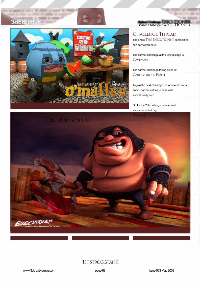
Each competition will have one main thread,
which starts with the brief at the top. All
entrants should post all WIPs, give feedback,
and generally laugh at the crazy ideas that are
emerging each month!
5th
Mistik
4th draleto
3rd chubu
include some graphical elements or text on your image. Renders of the
800 pixel dimension sound about right, but the winners will be featured in
3DCreative Magazine, so if you can create some higher resolution images
too, all the better!
There will be one competition per month, with the deadline being the end
of the month (GMT). For a valid entry, just make sure your nal image is
posted in the main competition thread before the deadline. We require
the top three winners to submit “Making Of” overview articles that will be
8/10/2019 3DCreative Magazine Issue 033 May 2008
http://slidepdf.com/reader/full/3dcreative-magazine-issue-033-may-2008 57/224
8/10/2019 3DCreative Magazine Issue 033 May 2008
http://slidepdf.com/reader/full/3dcreative-magazine-issue-033-may-2008 58/224
page 69www.3dcreativemag.com Issue 033 May 2008
Executioner Stylised Challenge
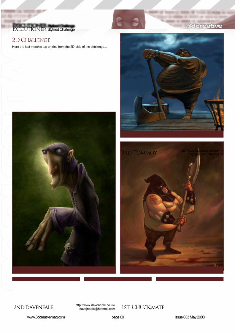
2D ChallengeHere are last month’s top entries from the 2D side of the challenge...
3rd Tommoy
2nd daveneale 1st Chuck,matehttp://www.daveneale.co.uk/[email protected]
[email protected]://www.thecartoonfactory.nl

8/10/2019 3DCreative Magazine Issue 033 May 2008
http://slidepdf.com/reader/full/3dcreative-magazine-issue-033-may-2008 59/224
page 70www.3dcreativemag.com Issue 033 May 2008
Stylised ChallengeExecutioner
Making Of’sHere are the “Making Of” from last month’s top
three winning entries...
3rd Pants
Concept After searching for hours on the Internet for
images of a bull, I nally sat down and started
doing some concept sketches. The style I
was going for was to emphasise the muscular
structure of the bull’s front end to create a
menacing look, and then place him in a funny
situation to create a contrast. After several failed
attempts at creating the look I wanted for my bull
(Fig.01), I consulted a friend to help me since
he has a more dened style to his illustrations.
With his drawing in hand (Fig.02) I quickly
eshed out a scene (Fig.03) and could nally
start modelling.
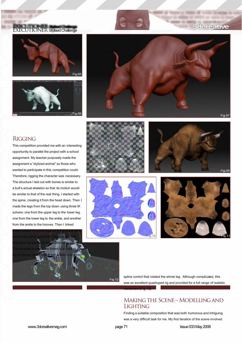
Modelling and TexturingThe modelling phase of this bull was a unique experience for me, since it
was my rst attempt with Zspheres in ZBrush. These tools are excellent
for creating organic models and textures quickly. The process I found to
be the most benecial was to take the basic Zsphered model (Fig.04 and
Fig.05) into 3ds Max, add all my hard edges (such as on the hooves,) add
any other necessary edge loops, and nally bring it back into ZBrush for
more tweaking (Fig.06 and Fig.07). I repeated this process several times
to get the desired look I wanted.
When I nally had the basic form I was looking for, I unwrapped the model
in Max (Fig.08) and textured him with ZBrush (Fig.09). I then dumped out
a normal map (Fig.10) and a texture map (Fig.11) and slapped them on
an exported model in 3ds Max, leaving myself a workable low poly, highly
detailed model.
8/10/2019 3DCreative Magazine Issue 033 May 2008
http://slidepdf.com/reader/full/3dcreative-magazine-issue-033-may-2008 60/224
page 71www.3dcreativemag.com Issue 033 May 2008
Executioner Stylised Challenge
RiggingThis competition provided me with an interesting
opportunity to parallel the project with a school
assignment. My teacher purposely made the
assignment a “stylized animal” so those who
wanted to participate in this competition could.
Therefore, rigging the character was necessary.
The structure I laid out with bones is similar to
a bull’s actual skeleton so that its motion would
be similar to that of the real thing. I started with
the spine, creating it from the head down. Then I
made the legs from the top down using three IK
solvers: one from the upper leg to the lower leg,
one from the lower leg to the ankle, and another
from the ankle to the hooves. Then I linked
those solvers to points located in the same spot,
and those points were then linked to controls
that were the bases for articulation (Fig.12).
The shoulder bones were linked to a point at the
top of the leg chain, which was linked to another
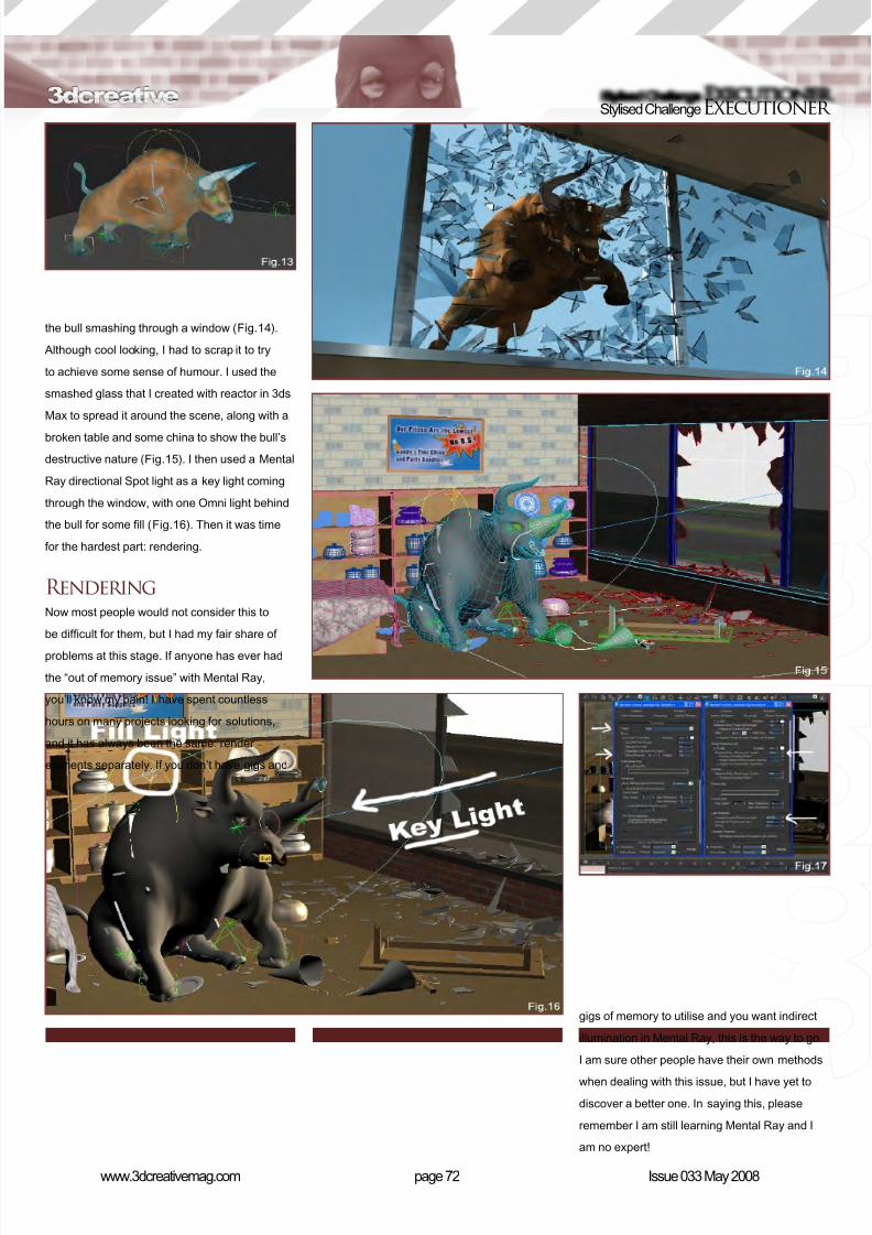
spline control that rotated the whole leg. Although complicated, this
was an excellent quadruped rig and provided for a full range of realistic
movement (Fig.13).
Making the Scene – Modelling andLightingFinding a suitable composition that was both humorous and intriguing
was a very difcult task for me. My rst iteration of the scene involved
8/10/2019 3DCreative Magazine Issue 033 May 2008
http://slidepdf.com/reader/full/3dcreative-magazine-issue-033-may-2008 61/224
page 72www.3dcreativemag.com Issue 033 May 2008
Stylised ChallengeExecutioner
the bull smashing through a window (Fig.14).
Although cool looking, I had to scrap it to try
to achieve some sense of humour. I used the
smashed glass that I created with reactor in 3ds
Max to spread it around the scene, along with a
broken table and some china to show the bull’s
destructive nature (Fig.15). I then used a Mental
Ray directional Spot light as a key light coming
through the window, with one Omni light behind
the bull for some ll (Fig.16). Then it was time
for the hardest part: rendering.
RenderingNow most people would not consider this to
be difcult for them, but I had my fair share of
problems at this stage. If anyone has ever had
the “out of memory issue” with Mental Ray,
you’ll know my pain! I have spent countless
hours on many projects looking for solutions,
and it has always been the same: render
elements separately. If you don’t have gigs and
gigs of memory to utilise and you want indirect
illumination in Mental Ray, this is the way to go.
I am sure other people have their own methods
when dealing with this issue, but I have yet to
discover a better one. In saying this, please
remember I am still learning Mental Ray and I
am no expert!
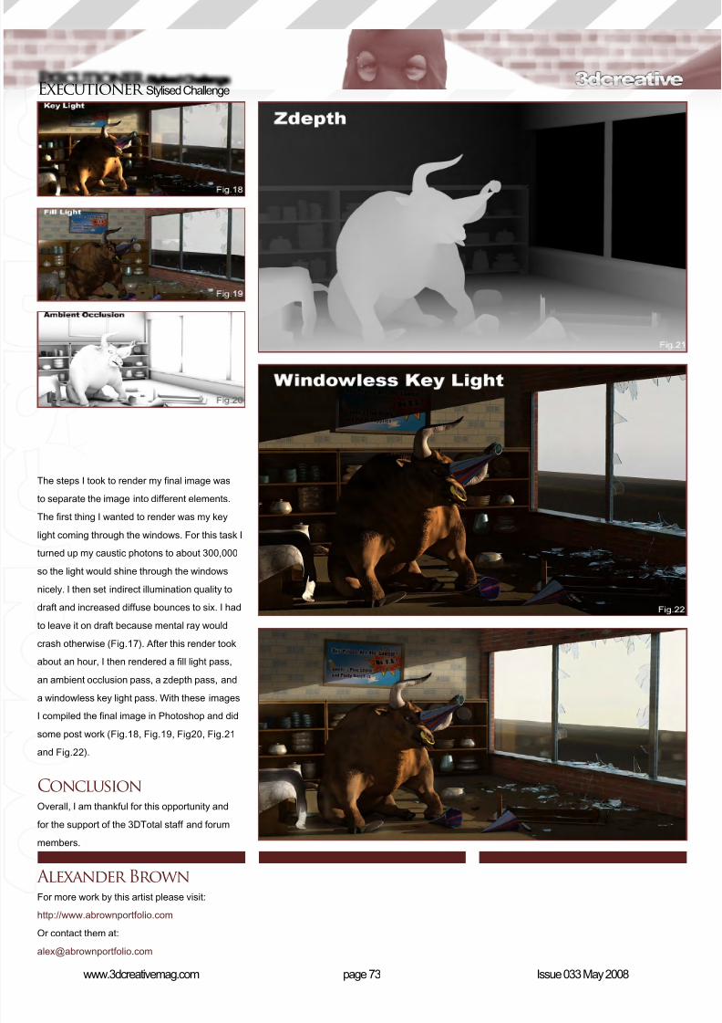
8/10/2019 3DCreative Magazine Issue 033 May 2008
http://slidepdf.com/reader/full/3dcreative-magazine-issue-033-may-2008 62/224
page 73www.3dcreativemag.com Issue 033 May 2008
Executioner Stylised Challenge
The steps I took to render my nal image was
to separate the image into different elements.
The rst thing I wanted to render was my key
light coming through the windows. For this task Iturned up my caustic photons to about 300,000
so the light would shine through the windows
nicely. I then set indirect illumination quality to
draft and increased diffuse bounces to six. I had
to leave it on draft because mental ray would
crash otherwise (Fig.17). After this render took
about an hour, I then rendered a ll light pass,
an ambient occlusion pass, a zdepth pass, and
a windowless key light pass. With these images
I compiled the nal image in Photoshop and did
some post work (Fig.18, Fig.19, Fig20, Fig.21
and Fig.22).
ConclusionOverall, I am thankful for this opportunity and
for the support of the 3DTotal staff and forum
members.
Alexander BrownFor more work by this artist please visit:
http://www.abrownportfolio.com
Or contact them at:
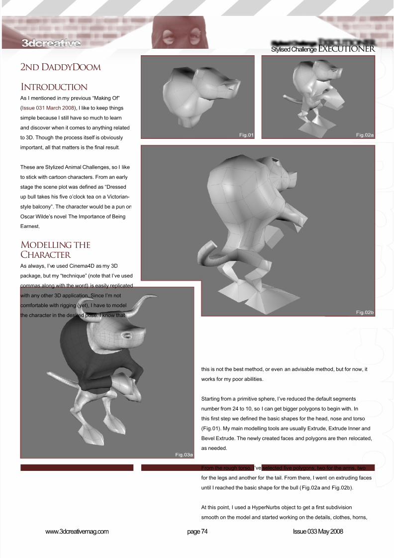
8/10/2019 3DCreative Magazine Issue 033 May 2008
http://slidepdf.com/reader/full/3dcreative-magazine-issue-033-may-2008 63/224
page 74www.3dcreativemag.com Issue 033 May 2008
Stylised ChallengeExecutioner
2nd DaddyDoom
Introduction
As I mentioned in my previous “Making Of”
(Issue 031 March 2008), I like to keep things
simple because I still have so much to learn
and discover when it comes to anything related
to 3D. Though the process itself is obviously
important, all that matters is the nal result.
These are Stylized Animal Challenges, so I like
to stick with cartoon characters. From an early
stage the scene plot was dened as “Dressed
up bull takes his ve o’clock tea on a Victorian-
style balcony”. The character would be a pun on
Oscar Wilde’s novel The Importance of Being
Earnest.
Modelling theCharacter
As always, I’ve used Cinema4D as my 3D
package, but my “technique” (note that I’ve used
commas along with the word) is easily replicated
with any other 3D application. Since I’m not
comfortable with rigging (yet), I have to model
the character in the desired pose. I know that
this is not the best method, or even an advisable method, but for now, it
works for my poor abilities.
Starting from a primitive sphere, I’ve reduced the default segments
number from 24 to 10, so I can get bigger polygons to begin with. In
this rst step we dened the basic shapes for the head, nose and torso
(Fig.01). My main modelling tools are usually Extrude, Extrude Inner and
Bevel Extrude. The newly created faces and polygons are then relocated,
as needed.
From the rough torso, I’ve selected ve polygons; two for the arms, two
for the legs and another for the tail. From there, I went on extruding faces
until I reached the basic shape for the bull (Fig.02a and Fig.02b).
At this point, I used a HyperNurbs object to get a rst subdivision
smooth on the model and started working on the details, clothes, horns,
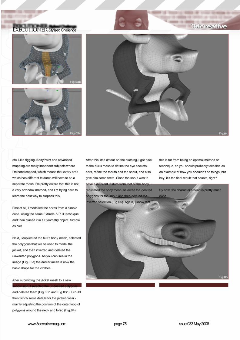
8/10/2019 3DCreative Magazine Issue 033 May 2008
http://slidepdf.com/reader/full/3dcreative-magazine-issue-033-may-2008 64/224
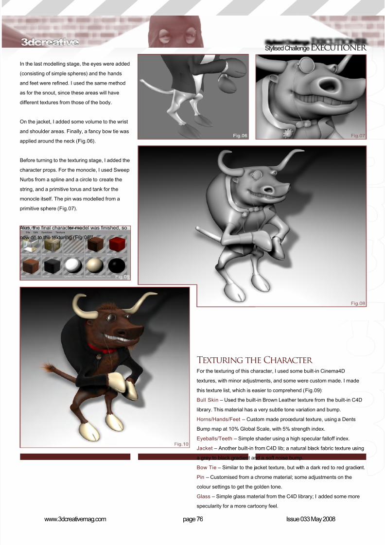
8/10/2019 3DCreative Magazine Issue 033 May 2008
http://slidepdf.com/reader/full/3dcreative-magazine-issue-033-may-2008 65/224
page 76www.3dcreativemag.com Issue 033 May 2008
Stylised ChallengeExecutioner
In the last modelling stage, the eyes were added
(consisting of simple spheres) and the hands
and feet were rened. I used the same method
as for the snout, since these areas will havedifferent textures from those of the body.
On the jacket, I added some volume to the wrist
and shoulder areas. Finally, a fancy bow tie was
applied around the neck (Fig.06).
Before turning to the texturing stage, I added the
character props. For the monocle, I used Sweep
Nurbs from a spline and a circle to create the
string, and a primitive torus and tank for themonocle itself. The pin was modelled from a
primitive sphere (Fig.07).
Alas, the nal character model was nished, so
now on to the texturing (Fig.08)!
Texturing the Character For the texturing of this character, I used some built-in Cinema4D
textures, with minor adjustments, and some were custom made. I madethis texture list, which is easier to comprehend (Fig.09):
Bull Skin – Used the built-in Brown Leather texture from the built-in C4D
library. This material has a very subtle tone variation and bump.
Horns/Hands/Feet – Custom made procedural texture, using a Dents
Bump map at 10% Global Scale, with 5% strength index.
Eyeballs/Teeth – Simple shader using a high specular falloff index.
Jacket – Another built-in from C4D lib; a natural black fabric texture using
a grey to black gradient and a soft noise bump.
Bow Tie – Similar to the jacket texture, but with a dark red to red gradient.
Pin – Customised from a chrome material; some adjustments on the
colour settings to get the golden tone.
Glass – Simple glass material from the C4D library; I added some more
specularity for a more cartoony feel.
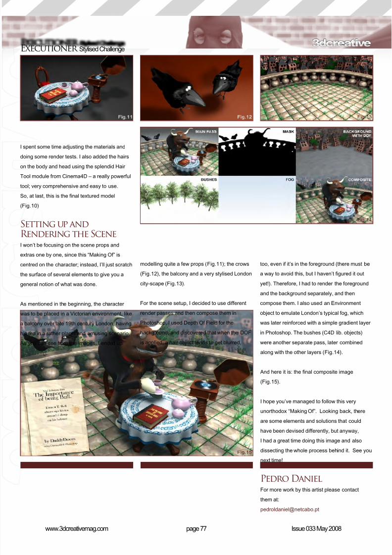
8/10/2019 3DCreative Magazine Issue 033 May 2008
http://slidepdf.com/reader/full/3dcreative-magazine-issue-033-may-2008 66/224
page 77www.3dcreativemag.com Issue 033 May 2008
Executioner Stylised Challenge
I spent some time adjusting the materials and
doing some render tests. I also added the hairs
on the body and head using the splendid Hair
Tool module from Cinema4D – a really powerful
tool; very comprehensive and easy to use.
So, at last, this is the nal textured model
(Fig.10)
Setting up andRendering the SceneI won’t be focusing on the scene props and
extras one by one, since this “Making Of” is
centred on the character; instead, I’ll just scratch
the surface of several elements to give you a
general notion of what was done.
As mentioned in the beginning, the character
was to be placed in a Victorian environment, like
a balcony over late 19th century London, having
his tea in a rather placid and amusing scenario.
As you can see from the images, I ended up
modelling quite a few props (Fig.11); the crows
(Fig.12), the balcony and a very stylised London
city-scape (Fig.13).
For the scene setup, I decided to use different
render passes and then compose them in
Photoshop. I used Depth Of Field for the
background, and discovered that when the DOF
is applied, a hair object tends to get blurred,
too, even if it’s in the foreground (there must be
a way to avoid this, but I haven’t gured it out
yet!). Therefore, I had to render the foreground
and the background separately, and then
compose them. I also used an Environment
object to emulate London’s typical fog, which
was later reinforced with a simple gradient layer
in Photoshop. The bushes (C4D lib. objects)
were another separate pass, later combined
along with the other layers (Fig.14).
And here it is: the nal composite image
(Fig.15).
I hope you’ve managed to follow this very
unorthodox “Making Of”. Looking back, there
are some elements and solutions that could
have been devised differently, but anyway,
I had a great time doing this image and also
dissecting the whole process behind it. See you
next time!
Pedro DanielFor more work by this artist please contact
them at:
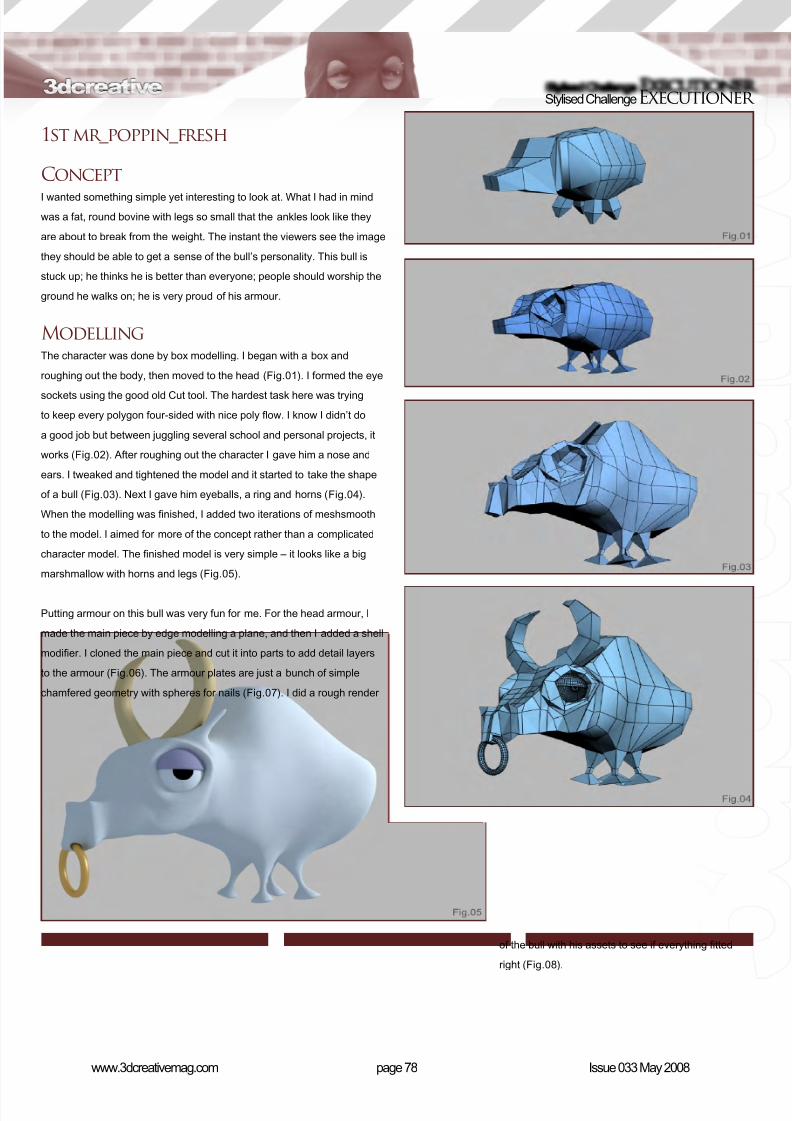
8/10/2019 3DCreative Magazine Issue 033 May 2008
http://slidepdf.com/reader/full/3dcreative-magazine-issue-033-may-2008 67/224
page 78www.3dcreativemag.com Issue 033 May 2008
Stylised ChallengeExecutioner
1st mr_poppin_fresh
ConceptI wanted something simple yet interesting to look at. What I had in mind
was a fat, round bovine with legs so small that the ankles look like they
are about to break from the weight. The instant the viewers see the image
they should be able to get a sense of the bull’s personality. This bull is
stuck up; he thinks he is better than everyone; people should worship the
ground he walks on; he is very proud of his armour.
ModellingThe character was done by box modelling. I began with a box and
roughing out the body, then moved to the head (Fig.01). I formed the eye
sockets using the good old Cut tool. The hardest task here was trying
to keep every polygon four-sided with nice poly ow. I know I didn’t do
a good job but between juggling several school and personal projects, it
works (Fig.02). After roughing out the character I gave him a nose and
ears. I tweaked and tightened the model and it started to take the shape
of a bull (Fig.03). Next I gave him eyeballs, a ring and horns (Fig.04).
When the modelling was nished, I added two iterations of meshsmooth
to the model. I aimed for more of the concept rather than a complicated
character model. The nished model is very simple – it looks like a big
marshmallow with horns and legs (Fig.05).
Putting armour on this bull was very fun for me. For the head armour, I
made the main piece by edge modelling a plane, and then I added a shell
modier. I cloned the main piece and cut it into parts to add detail layers
to the armour (Fig.06). The armour plates are just a bunch of simple
chamfered geometry with spheres for nails (Fig.07). I did a rough render
of the bull with his assets to see if everything tted
right (Fig.08).

8/10/2019 3DCreative Magazine Issue 033 May 2008
http://slidepdf.com/reader/full/3dcreative-magazine-issue-033-may-2008 68/224
page 79www.3dcreativemag.com Issue 033 May 2008
Executioner Stylised Challenge
TexturingI really enjoyed the texturing process because
I painted all the maps in Photoshop with a
Wacom tablet. I used Google to nd all my
reference photos of china vases and dragon
designs. I used Vray material for the gold on
the armour and shield. The dragon design on
the neck armour was nothing special - just a
bump map. The carpet was just a red noise map
(Fig.09, Fig.10 and Fig.11). To set the mood,
I added a painting of a laughing Buddha in the
bottom right. I wanted the Buddha painting to
complement the bull (Fig.12).
RenderingMy goal wasn’t to render a realistic looking bull.
I wanted the render to have a nice, soft, cartoon
feel. The lighting was simple: one Vray light in
the top right corner pointing at the bull. Again,
due to time constraints, I didn’t ddle with the
light much. Plus, if it looked good, there was no
need for a complicated lighting scheme. I placed
the light in a way that best gave off highlights on
the shield and armour. I had Global Illumination
on, with irradiance map for primary bounces and
Quasi-Monte Carlo for secondary bounces. I
also turned on the environment skylight override
to give it the overall soft shadow (Fig.13).
Post Work I didn’t do any post work on the piece that was
in the contest. However, I’ve recently made
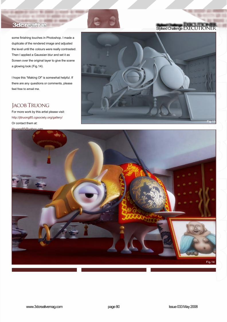
8/10/2019 3DCreative Magazine Issue 033 May 2008
http://slidepdf.com/reader/full/3dcreative-magazine-issue-033-may-2008 69/224
page 80www.3dcreativemag.com Issue 033 May 2008
Stylised ChallengeExecutioner
some nishing touches in Photoshop. I made a
duplicate of the rendered image and adjusted
the level until the colours were really contrasted.
Then I applied a Gaussian blur and set it asScreen over the original layer to give the scene
a glowing look (Fig.14).
I hope this “Making Of” is somewhat helpful. If
there are any questions or comments, please
feel free to email me.
Jacob Truong
For more work by this artist please visit:http://jttruong85.cgsociety.org/gallery/
Or contact them at:
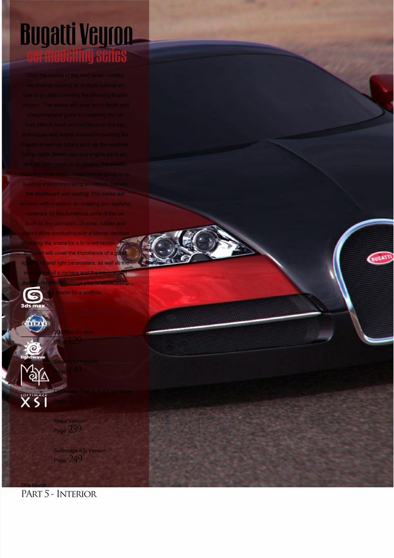
8/10/2019 3DCreative Magazine Issue 033 May 2008
http://slidepdf.com/reader/full/3dcreative-magazine-issue-033-may-2008 70/224
Over the course of the next seven months
we shall be running an in depth tutorial on
how to go about creating the amazing BugattiVeyron. The series will cover an in depth and
comprehensive guide to modelling the car
from start to nish and will focus on the key
techniques and stages invloved in building the
chassis as well as details such as the windows,
lights, vents, petrol caps and engine parts etc.
We will then move on to creating the wheels
including tyres and hubcaps before going on to
building and incorporating an interior, namely
the dashboard and seating. The series willproceed with a section on creating and applying
materials for the numerous parts of the car
such as the paintwork, chrome, rubber and
glass before concluding with a tutorial devoted
to setting the scene for a nished render. This
nal part will cover the importance of a good
lighting rig and light parameters, as well as the
importance of a camera and the integral part
that the rendering settings play in showcasing
the model for a portfolio.
3DSMax Version
Page 129
Cinema4D Version
Page 149
Lightwave Part 3, 4 & 5 Versions
Page 163
Maya Version
Page 239
Softimage XSi Version
Page 249
This Month :
PArt 5 - Interior
Bugatti Veyron car modelling series
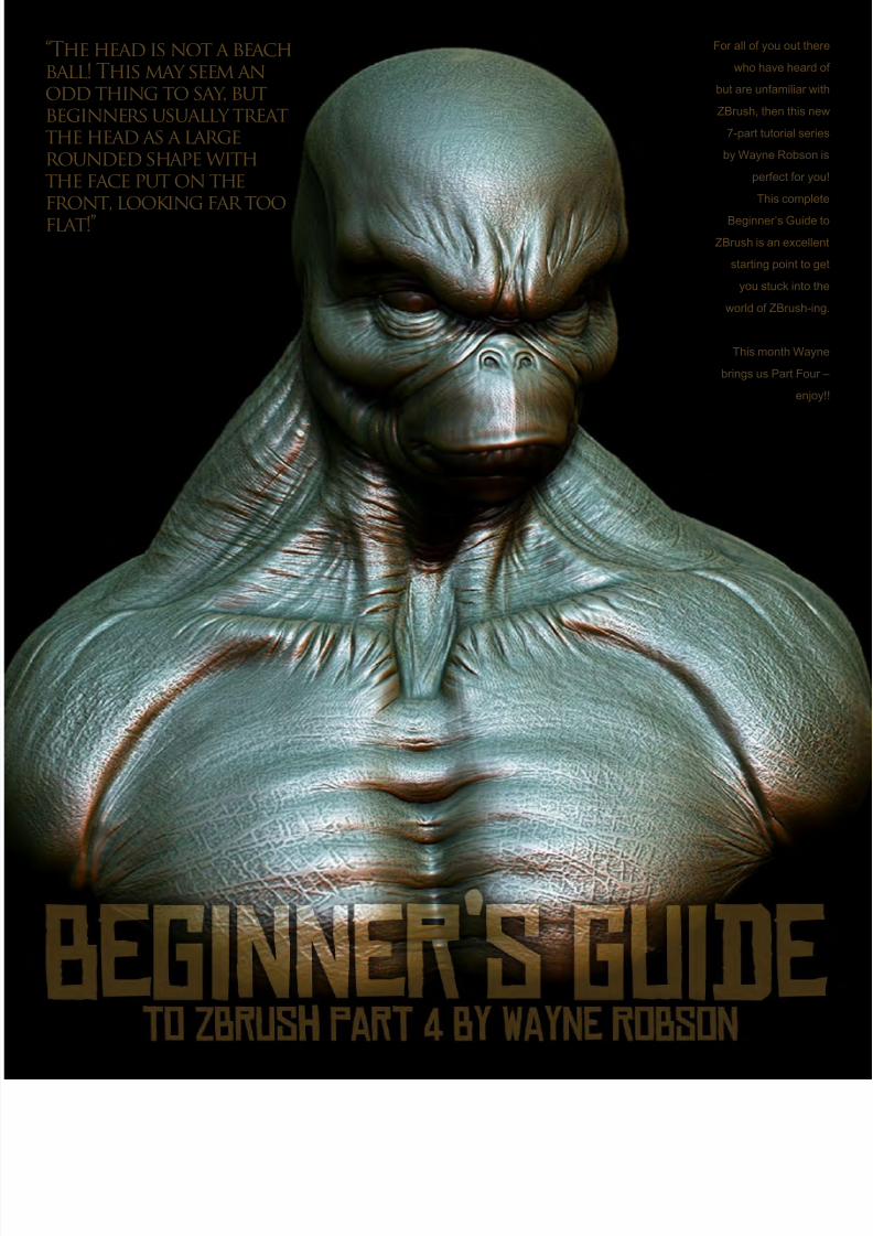
8/10/2019 3DCreative Magazine Issue 033 May 2008
http://slidepdf.com/reader/full/3dcreative-magazine-issue-033-may-2008 71/224
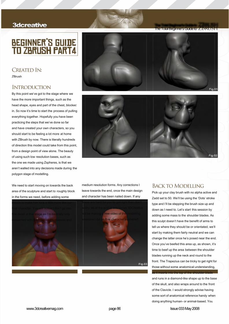
8/10/2019 3DCreative Magazine Issue 033 May 2008
http://slidepdf.com/reader/full/3dcreative-magazine-issue-033-may-2008 72/224
page 86www.3dcreativemag.com Issue 033 May 2008
The Total Beginner’s Guide to ZBrush
Created In:ZBrush
IntroductionBy this point we’ve got to the stage where we
have the more important things, such as the
head shape, eyes and part of the chest, blocked
in. So now it’s time to start the process of pulling
everything together. Hopefully you have been
practicing the steps that we’ve done so far
and have created your own characters, so you
should start to be feeling a lot more at home
with ZBrush by now. There is literally hundreds
of direction this model could take from this point,
from a design point of view alone. The beauty
of using such low resolution bases, such as
the one we made using Zspheres, is that we
aren’t walled into any decisions made during the
polygon stage of modelling.
We need to start moving on towards the back
area of the sculpture and start to roughly block
in the forms we need, before adding some
details to make him look a little more like our
nal character. You will notice I don’t go into
ne detail at this stage as I’m basically only
concerned with the main forms, masses and
medium resolution forms. Any corrections I
leave towards the end, once the main design
and character has been nailed down. If any
areas are hard for you to get right then don’t
worry, as at the end of this series 3DCreative
will be making a free video of the modelling
sessions I did on this character available!!
Back to ModellingPick up your clay brush with no alpha active and
Zadd set to 50. We’ll be using the ‘Dots’ stroke
type and I’ll be stepping the brush size up and
down as I need to. Let’s start this session by
adding some mass to the shoulder blades. As
this sculpt doesn’t have the benet of arms to
tell us where they should be or orientated, we’ll
start by making them fairly neutral and we can
change the latter once he’s posed near the end.
Once you’ve beefed this area up, as shown, it’s
time to beef up the area between the shoulder
blades running up the neck and round to the
front. The Trapezius can be tricky to get right for
those without some anatomical understanding,
as it inserts into the top of the shoulder blade
and runs in a diamond-like shape up to the base
of the skull, and also wraps around to the front
of the Clavicle. I would strongly advise having
some sort of anatomical reference handy when
doing anything human- or animal-based. You
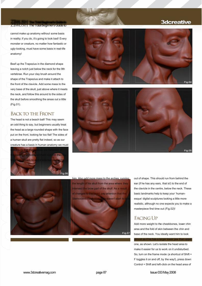
8/10/2019 3DCreative Magazine Issue 033 May 2008
http://slidepdf.com/reader/full/3dcreative-magazine-issue-033-may-2008 73/224
page 87www.3dcreativemag.com Issue 033 May 2008
ZBrush The Total Beginner’s Guide to
cannot make up anatomy without some basis
in reality; if you do, it’s going to look bad! Every
monster or creature, no matter how fantastic or
ugly-looking, must have some basis in real-lifeanatomy!
Beef up the Trapezius in the diamond shape
leaving a notch just below the neck for the 9th
vertebrae. Run your clay brush around the
shape of the Trapezius and make it attach to
the front of the clavicle. Add some mass to the
very base of the skull, just above where it meets
the neck, and follow this around to the sides of
the skull before smoothing the areas out a little(Fig.01).
Back to the FrontThe head is not a beach ball! This may seem
an odd thing to say, but beginners usually treat
the head as a large rounded shape with the face
put on the front, looking far too at! The sides of
a human skull are pretty at indeed, so as our
creature has a basis in human anatomy we must
make sure that those areas are attened. In
this case I also hollowed them out with the clay
brush, as shown, to add a less human feel to
him. Also add more mass to the arches, running
the length of his skull from the area where they
intersect the brow part of the skull. As a result
of changes to the head, pay attention that the
Sternocleidomastoid muscle doesn’t start to look
out of shape. This should run from behind the
ear (if he has any ears, that is!) to the end of
the clavicle in the centre, below the neck. These
basic landmarks help to keep your ‘human-
esque’ digital sculptures looking a little more
realistic, although no one expects you to make a
masterpiece rst time out (Fig.02)!
Facing Up Add more weight to the cheekbones, lower chin
area and the fold of skin between the chin and
base of the neck. You ideally want him to look
almost as if he has a larger lower jaw than upper
one, as shown. Let’s isolate the head area to
make it easier for us to work on it undisturbed.So, turn on the frame mode (a shortcut of Shift +
F toggles it on and off, by the way!), press down
Control + Shift and left-click on the head area of

8/10/2019 3DCreative Magazine Issue 033 May 2008
http://slidepdf.com/reader/full/3dcreative-magazine-issue-033-may-2008 74/224
page 88www.3dcreativemag.com Issue 033 May 2008
The Total Beginner’s Guide to ZBrush
the mesh. This will hide every other part of the
mesh (although it doesn’t affect other subtools,
such as the eyes). If you do the same shortcut
again, only this time outside your model, it willreveal the previously hidden areas (Fig.03).
Using your Standard brush with its default
settings, carve a line into the face that will make
our mouth area and then start to build up the
lips. Add some mass to the upper and lower
eyelids and, to help make them look less like
‘holes in the mesh’ (although we’ll address that
a bit later), paint a mask by holding down your
control key near the outer edge of the bottomlid and then adding some mass to the top lid
over this, to give us a nice demarcation line. Do
the same with the inside of the lower lid, near
the nasal, until it looks as shown in the image
(Fig.04).
Let’s use our move brush now to change the
shape of the head a little, especially in the
mouth area. Step down a few subdivision levels
and pull the edges of the mouth outwards a bit.Then, from a side on view (remembering you
can hold down the Shift key to snap it into a
proper side on view), pull the mouth edges back
a touch (Fig.05).
Step back up your subdivision levels again and
paint a mask over the eye socket areas, then
blur this mask by holding down the Shift key
and left-clicking on part of the masked area.
(You can also blur the mask from the masking
section of the tools palette.) Using the move
brush again, pull the brows into an angry-looking
position, as shown before unmasking the area.
If you nd the transition of the brow to the upper
eye area a bit too harsh, use your smooth brush
on a lower subdivision level before stepping
up again and smoothing out any areas that still
need it (Fig.06).
Again, paint a mask over the eye socket area
and then invert it by either going into the
masking section of the Tool palette or by holding
down the control key and left-clicking outside
your model. Then, using a smaller move brush,
start to pull the eyelids into a more pleasing
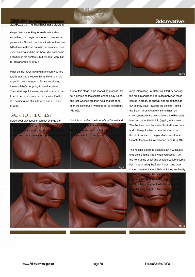
8/10/2019 3DCreative Magazine Issue 033 May 2008
http://slidepdf.com/reader/full/3dcreative-magazine-issue-033-may-2008 75/224
page 89www.3dcreativemag.com Issue 033 May 2008
ZBrush The Total Beginner’s Guide to
shape. We are looking for realism but also
something that helps the model to have some
personality. Smooth the transition from the lower
lid to the cheekbone out a bit, as skin stretchesover this area and the fat there. We want some
denition in his anatomy, but we don’t want him
to look anorexic (Fig.07)!
Mask off the lower jaw and make sure you are
totally masking the lower lip, and then pull the
upper lip down to meet it. As we are closing
the mouth he’s not going to need any teeth.
Then start to pull the almost-beak shape of the
front of his mouth area out, as shown. Do thisin a combination of a side view and a ¾ view
(Fig.08).
Back to the ChestSelect your clay tubes brush but change the
alpha from its default to Alpha 01, which is the
1st round alpha. I save this out and have it set
as a custom brush on my set up as I nd I use it
a lot at this stage in the modelling process. It’s
not as harsh as the square-shaped clay tubesand less washed out than no alpha set at all,
as in the clay brush (when its set to its default)
(Fig.09).
Use this to beef up the front of the Deltoid and
carve some indentations into the Pectoral area.
These striations aren’t technically “correct”
but they do help the chest area to look slightly
more interesting until later on. Start by carving
the area in and then add mass between thesecarved in areas, as shown, and smooth things
out as they travel towards the deltoid. Taking
the Slash1 brush, carve in some lines, as
shown, beneath the deltoid where the Pectorals
intersect under the deltoid (again, as shown).
The Pectoral muscles are in 5 strip-like sections,
and I often pull a line in near the armpit on
the Pectoral area to help add a bit of interest.
Smooth these out a fair bit once done (Fig.10).
The nest bit is hard to describe but it will make
total sense in the video when you see it… On
the front of the chest and shoulders, carve some
light lines in using the Slash1 brush and then
smooth them out about 90% until they are barely
visible. These help the process of detailing later
on to look a little more real, and are done “by
feel” to a large degree. Go to the face and do
a similar thing, only this time you are carving in
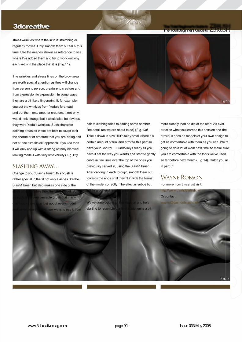
8/10/2019 3DCreative Magazine Issue 033 May 2008
http://slidepdf.com/reader/full/3dcreative-magazine-issue-033-may-2008 76/224
page 90www.3dcreativemag.com Issue 033 May 2008
The Total Beginner’s Guide to ZBrush
stress wrinkles where the skin is stretching or
regularly moves. Only smooth them out 50% this
time. Use the images shown as reference to see
where I’ve added them and try to work out whyeach set is in the place that it is (Fig.11).
The wrinkles and stress lines on the brow area
are worth special attention as they will change
from person to person, creature to creature and
from expression to expression. In some ways
they are a bit like a ngerprint. If, for example,
you put the wrinkles from Yoda’s forehead
and put them onto another creature, it not only
would look strange but it would also be obviousthey were Yoda’s wrinkles. Such character
dening areas as these are best to sculpt to t
the character or creature that you are doing and
not a “one size ts all” approach. If you do then
it will only end up with a string of fairly identical
looking models with very little variety (Fig.12)!
Slashing Away…Change to your Slash2 brush; this brush is
rather special in that it not only slashes like theSlash1 brush but also makes one side of the
slash protrude while the other stays level. So,
as such, it’s a very versatile brush that many
overlook – I use it on just about every model
and never cease nding new ways to use it from
hair to clothing folds to adding some harsher
ne detail (as we are about to do) (Fig.13)!
Take it down in size till it’s fairly small (there’s a
certain amount of trial and error to this part so
have your Control + Z undo keys ready till you
have it set the way you want!) and start to gently
carve in ne lines over the top of the ones you
previously carved in, using the Slash1 brush.
After carving in each ‘group’, smooth them out
towards the ends until they t in with the formsof the model correctly. The effect is subtle but
will help our end result a great deal.
We’ve done quite a lot this session and he’s
starting to resemble our nal sculpt quite a bit
more closely than he did at the start. As ever,
practice what you learned this session and the
previous ones on models of your own design to
get as comfortable with them as you can. We’re
going to do a lot of work next time so make sure
you are comfortable with the tools we’ve used
so far before next month (Fig.14). Catch you all
in part 5!
Wayne RobsonFor more from this artist visit:
http://www.dashdotslash.net
Or contact:

8/10/2019 3DCreative Magazine Issue 033 May 2008
http://slidepdf.com/reader/full/3dcreative-magazine-issue-033-may-2008 77/224
In this “Making Of” Simon Reeves has
created this piece of artwork based on
the way cars effect the environment.
He explains how he created “Eco
Wrestle” and also talks about the
reason for creating
this unique piece.
“I wanted to attempt a very illustrative stylefor the image; quitecolourful, distorted
and almost cartoony, whilst keeping somerealistic elementsto hold it alltogether ”

8/10/2019 3DCreative Magazine Issue 033 May 2008
http://slidepdf.com/reader/full/3dcreative-magazine-issue-033-may-2008 78/224
page 94www.3dcreativemag.com Issue 033 May 2008
Making Of Eco Wrestle
illumination. These lights were all set to invisible,
not reection or affecting specular, so that
“lightboxes” around the scene were used for
something to reect. In the image below you can
see the lightbox textures I painted in Photoshop
that were used so the lightboxes were not just a
pure white material (Fig.02).
In the rest of the scene, the ropes, corners and
the lighting rig were made to suit the camera,
so if you view them from another angle you can
see that they are quite a strange shape, but this
didn’t matter as I only intended them to be seen
through the one camera.
This is also true for a few other things: for
instance, the front wheels on the car on the
bottom are stretched out twice the distance they
should be from underneath the body, but without
that it was hard to read them clearly.
ConceptFor this project I had the idea of two cars
wrestling with each other. Originally I had it the
other way around, with a larger car (4x4 etc.)
overpowering a smaller car. But a moment of
inspiration sent me in another direction, and I
decided to switch the roles of the cars, changing
large verses small, to “efcient” verses “gas
guzzler”.
I wanted to attempt a very illustrative style for
the image; quite colourful, distorted and almost
cartoony, whilst keeping some realistic elements
to hold it all together. I also wanted to treat the
project as if it were a job, so this meant setting
myself a deadline and trying to be as efcient
as possible – such as using a lot of post work
and models already at my disposal in my library
(Fig.01).
CompositionThe rst thing I did for the scene was to bring in
the car models, place them roughly in the right
position together, and pin down an appropriate
camera angle as early as possible – to make the
post work easier for one thing. I had them sitting
on a basic oor, which received shadows but
had no diffuse as this was painted in 2D in the
compositing stage.
The car models were lit by placing a few large
Vray area lights - considering the nature of
the scene and the use of such large area
lights, I decided I didn’t really need any global
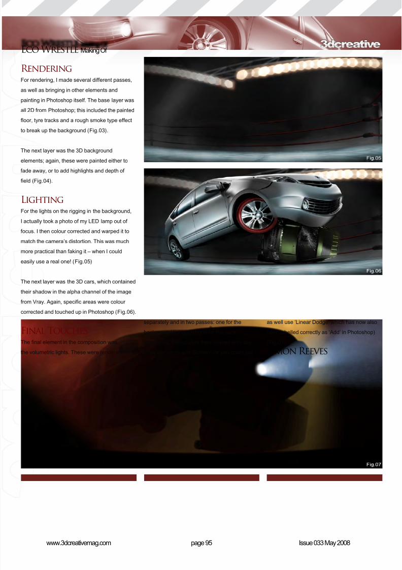
8/10/2019 3DCreative Magazine Issue 033 May 2008
http://slidepdf.com/reader/full/3dcreative-magazine-issue-033-may-2008 79/224
page 95www.3dcreativemag.com Issue 033 May 2008
Eco Wrestle Making Of
RenderingFor rendering, I made several different passes,
as well as bringing in other elements and
painting in Photoshop itself. The base layer was
all 2D from Photoshop; this included the painted
oor, tyre tracks and a rough smoke type effect
to break up the background (Fig.03).
The next layer was the 3D background
elements; again, these were painted either to
fade away, or to add highlights and depth of
eld (Fig.04).
LightingFor the lights on the rigging in the background,
I actually took a photo of my LED lamp out of
focus. I then colour corrected and warped it to
match the camera’s distortion. This was much
more practical than faking it – when I could
easily use a real one! (Fig.05)
The next layer was the 3D cars, which contained
their shadow in the alpha channel of the image
from Vray. Again, specic areas were colour
corrected and touched up in Photoshop (Fig.06).
Final TouchesThe nal element in the composition was
the volumetric lights. These were rendered
separately and in two passes: one for the
background lights and one for the car’s
headlights. These were then layered onto the
other elements with ‘Screen’ (or you could just
as well use ‘Linear Dodge’ which has now also
been labelled correctly as ‘Add’ in Photoshop)
(Fig.07).
Simon Reeves
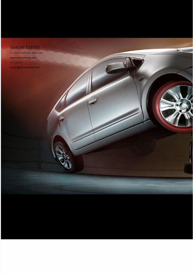
8/10/2019 3DCreative Magazine Issue 033 May 2008
http://slidepdf.com/reader/full/3dcreative-magazine-issue-033-may-2008 80/224
Simon ReevesFor more from this artist visit:
www.simonreeves.com
Or contact:
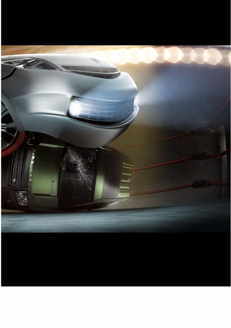
8/10/2019 3DCreative Magazine Issue 033 May 2008
http://slidepdf.com/reader/full/3dcreative-magazine-issue-033-may-2008 81/224
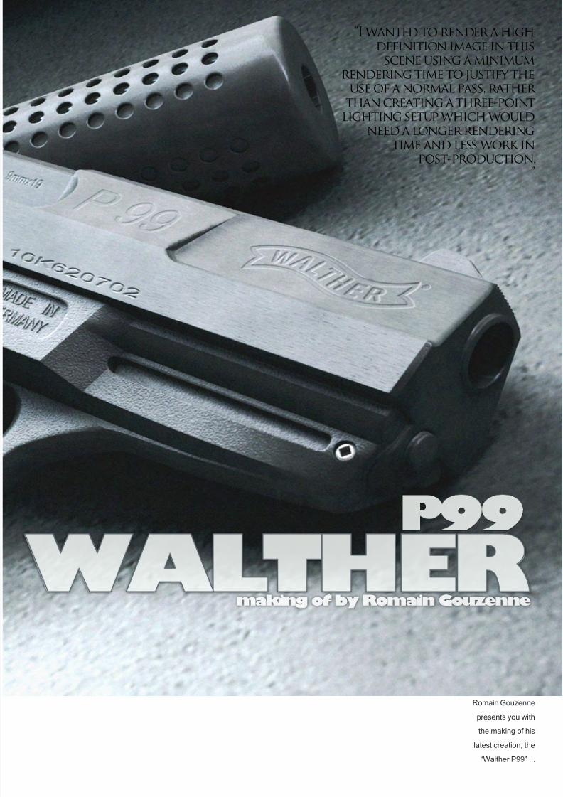
8/10/2019 3DCreative Magazine Issue 033 May 2008
http://slidepdf.com/reader/full/3dcreative-magazine-issue-033-may-2008 82/224
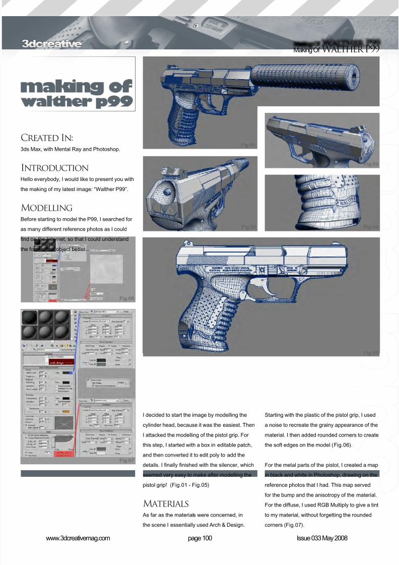
8/10/2019 3DCreative Magazine Issue 033 May 2008
http://slidepdf.com/reader/full/3dcreative-magazine-issue-033-may-2008 83/224
page 100www.3dcreativemag.com Issue 033 May 2008
Making Of Walther P99
Created In:3ds Max, with Mental Ray and Photoshop.
IntroductionHello everybody, I would like to present you with
the making of my latest image: “Walther P99”.
ModellingBefore starting to model the P99, I searched for
as many different reference photos as I could
nd on the Internet, so that I could understand
the form of the object better.
I decided to start the image by modelling the
cylinder head, because it was the easiest. Then
I attacked the modelling of the pistol grip. For
this step, I started with a box in editable patch,
and then converted it to edit poly to add the
details. I nally nished with the silencer, which
seemed very easy to make after modelling the
pistol grip! (Fig.01 - Fig.05)
Materials As far as the materials were concerned, in
the scene I essentially used Arch & Design.
Starting with the plastic of the pistol grip, I used
a noise to recreate the grainy appearance of the
material. I then added rounded corners to create
the soft edges on the model (Fig.06).
For the metal parts of the pistol, I created a map
in black and white in Photoshop, drawing on the
reference photos that I had. This map served
for the bump and the anisotropy of the material.
For the diffuse, I used RGB Multiply to give a tint
to my material, without forgetting the rounded
corners (Fig.07).
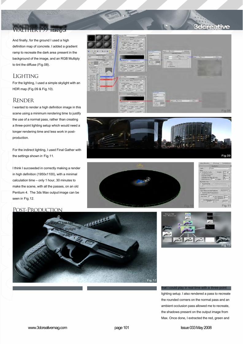
8/10/2019 3DCreative Magazine Issue 033 May 2008
http://slidepdf.com/reader/full/3dcreative-magazine-issue-033-may-2008 84/224
page 101www.3dcreativemag.com Issue 033 May 2008
Walther P99 Making Of
And nally, for the ground I used a high
denition map of concrete. I added a gradient
ramp to recreate the dark area present in the
background of the image, and an RGB Multiplyto tint the diffuse (Fig.08).
LightingFor the lighting, I used a simple skylight with an
HDR map (Fig.09 & Fig.10).
Render I wanted to render a high denition image in this
scene using a minimum rendering time to justify
the use of a normal pass, rather than creatinga three-point lighting setup which would need a
longer rendering time and less work in post-
production.
For the indirect lighting, I used Final Gather with
the settings shown in Fig.11.
I think I succeeded in correctly making a render
in high denition (1950x1100), with a minimal
calculation time – only 1 hour, 30 minutes tomake the scene, with all the passes, on an old
Pentium 4. The 3ds Max output image can be
seen in Fig.12.
Post-ProductionPost production was the most important step
in the project. Up until this stage, I just had an
image with a at light created by the skylight.
Because of this, I rendered a normal pass so
that I could play in real time with a three-point
lighting setup. I also rendered a pass to recreate
the rounded corners on the normal pass and anambient occlusion pass allowed me to recreate,
the shadows present on the output image from
Max. Once done, I extracted the red, green and
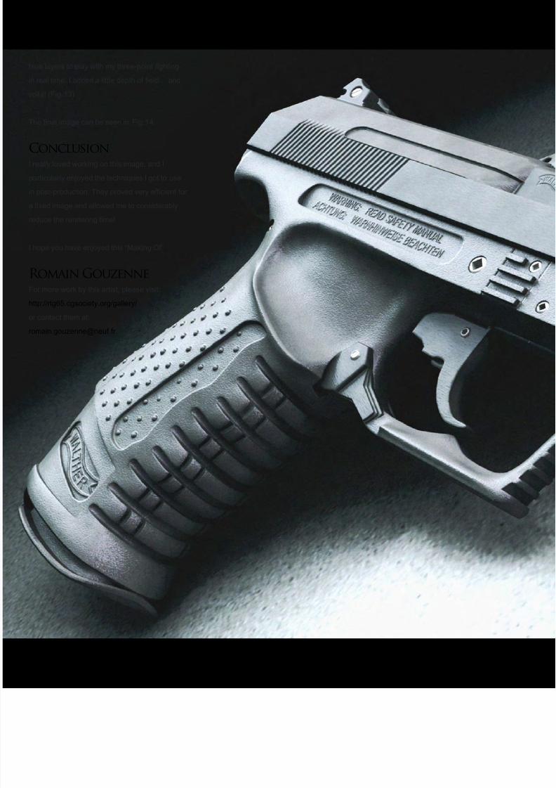
8/10/2019 3DCreative Magazine Issue 033 May 2008
http://slidepdf.com/reader/full/3dcreative-magazine-issue-033-may-2008 85/224
blue layers to play with my three-point lighting
in real time. I added a little depth of eld… and
voila! (Fig.13)
The nal image can be seen in Fig.14.
ConclusionI really loved working on this image, and I
particularly enjoyed the techniques I got to use
in post-production. They proved very efcient for
a xed image and allowed me to considerably
reduce the rendering time!
I hope you have enjoyed this “Making Of”.
Romain GouzenneFor more work by this artist, please visit:
http://rtg65.cgsociety.org/gallery/
or contact them at:
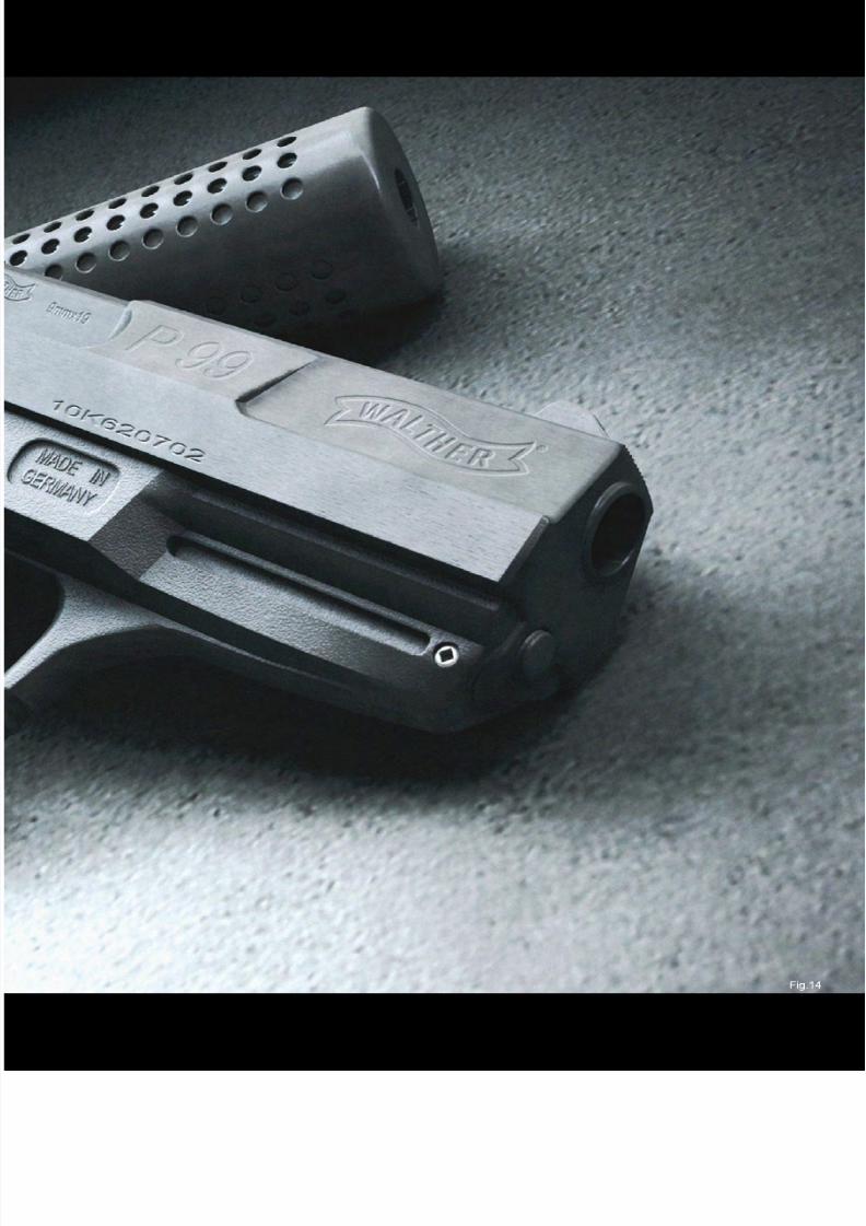
8/10/2019 3DCreative Magazine Issue 033 May 2008
http://slidepdf.com/reader/full/3dcreative-magazine-issue-033-may-2008 86/224
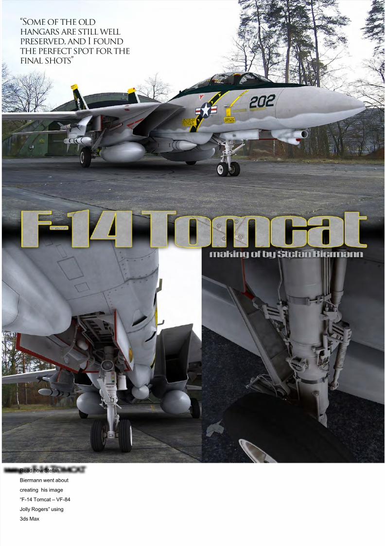
8/10/2019 3DCreative Magazine Issue 033 May 2008
http://slidepdf.com/reader/full/3dcreative-magazine-issue-033-may-2008 87/224
Making Of F-14 Tomcat
Read how Stefan
Biermann went about
creating his image
“F-14 Tomcat – VF-84
Jolly Rogers” using
3ds Max
“Some of the oldhangars are still wellpreserved, and I foundthe perfect spot for thefinal shots”

8/10/2019 3DCreative Magazine Issue 033 May 2008
http://slidepdf.com/reader/full/3dcreative-magazine-issue-033-may-2008 88/224
page 107www.3dcreativemag.com Issue 033 May 2008
F-14 Tomcat Making Of
things related to the F14 (Fig.01 & Fig.02). I
can’t overstate how helpful this single page was
in the creation of this project! Other useful sites
were http://www.airliners.net, and lastly, http://
www.primeportal.net.
ModellingI realised early on that this project would be a
challenge. Looking at the mere insanity that
was the nose landing gear bay (Fig.03) was an
intimidating sight for sure, but in the end it was
quite fun working with such a detailed model.
3D Studio Max performed admirably in this
difcult environment and I didn’t run into many
modelling-related problems.
I began by setting up a set of high-resblueprints, given to me by a friend (two 4096
sheets with all the standard views), which
proved to be very helpful in outlining the
Created In:3D Studio Max 9 (Modelling, UV), Photoshop
CS3 (Texturing, Postwork), V-Ray 1.5
IntroductionThis project is the largest I’ve ever attempted.
It’s been in development for around six months
now, with me working constantly on it for a
couple of hours each day. It was supposed to be
the leading project for my portfolio, and I wanted
to create something big for that.
ConceptWhen I began working on this plane, the only
thing I knew for certain was that I wanted to
make an F-14, or more specically, an F-14A.
In terms of the nal environment, or the setup
of the scene, I had no rm plans. The in-ight
render of the F-14A was my main goal and it
turned out to be one I lled almost completely
- the only major change being that my plane’s
engines ended up belonging to a F14A+/B.
I used a number of reference photos for this
project, most of them take from the truly
excellent site http://www.anft.net – a very
complete and wonderful reference work for all

8/10/2019 3DCreative Magazine Issue 033 May 2008
http://slidepdf.com/reader/full/3dcreative-magazine-issue-033-may-2008 89/224
page 108www.3dcreativemag.com Issue 033 May 2008
Making Of F-14 Tomcat
general shapes of this plane. As I was outlining
the basic shape, I kept looking for reference
images, both for the overall form and for small
details. Primeportal.net supplied those images,but I didn’t stumble across that one until the
modelling stage was almost completed. I had to
make do with smaller images for the most part
and do a little bit of guess work for small details
every now and then, especially for the landing
gear bays (Fig.04 & Fig.05).
UVW Mapping andTexturingUnwrapping this plane was a simple task for
the most part, since I could planar map large
regions and assemble them into nice, big UV
shells. However, Max decided to throw me an
extremely nasty surprise once I started to create
textures! It turns out that mesh smoothing can
wreak havoc on UV seams, wildly stretching
the UV verts along the seams for no apparent
reason (Fig.06 and Fig.07). This caused me a
major headache and several days of delay while
I collapsed the meshsmooth in the modier

8/10/2019 3DCreative Magazine Issue 033 May 2008
http://slidepdf.com/reader/full/3dcreative-magazine-issue-033-may-2008 90/224
page 109www.3dcreativemag.com Issue 033 May 2008
F-14 Tomcat Making Of
stack and xed the seams by hand. (Even after
a thorough search on the web, this was the only
way I could nd to x the problem.)
The textures themselves are several 4096
sheets (Fig.08 and Fig.09) and pushed the
limits of my machine, using dozens of layers
and vector shapes. Still, this was one of the
most fun phases: watching this project come
together. For the squadron markings, I decided
to use those of the VF-84 “Jolly Rogers”. The
reasons are simple: the squadron is one of
the most famous ones, they t the era of the
F14A, and lastly, their colours and symbols are
strong and vibrant, especially on the early era
paint scheme. I wanted authenticity as much as
possible, so I looked up the Federal Standard
colour codes and their RGB counterparts,
ensuring the plane would look exactly the way
it should.
Rendering andEnvironment
At this stage, I had to decide upon an
environment for the plane. I opted against a mid-
ight scenario and decided to park the plane on
an airstrip somewhere, which would let me show
off more of the detail on it.
I chose to create a composited image, using
pictures I took myself at the local airport which
formerly served as a Canadian F104 Starghter

8/10/2019 3DCreative Magazine Issue 033 May 2008
http://slidepdf.com/reader/full/3dcreative-magazine-issue-033-may-2008 91/224
page 110www.3dcreativemag.com Issue 033 May 2008
Making Of F-14 Tomcat
airbase. Some of the old hangars are still well
preserved, and I found the perfect spot for the
nal shots. The limiting factor was the rather
low-quality camera I had at my disposal, but in
the end the results were satisfying enough. As a
side note, I didn’t put down any measurements,
but rather took the photos guessing where
the plane would be depending on my position
(Fig.10 and Fig.11) – when assembling the
cameras in Max later on, it turned out I was
pretty damn accurate with my guesses, too!
Rendering was done with V-Ray, using a
lightprobe I created at the airport to ensure
realistic lighting. I added a weak direct light to
enhance shadows on the ground, and after a
bit of calibration and material testing, I rendered
out the nal images, each rendered at 1024
resolution and taking between 1:20 and 1:40
hours (Fig.12 - Fig.17).
Stefan BiermannFor more from this artist visit:
http://www.psistorm.org
Or contact:
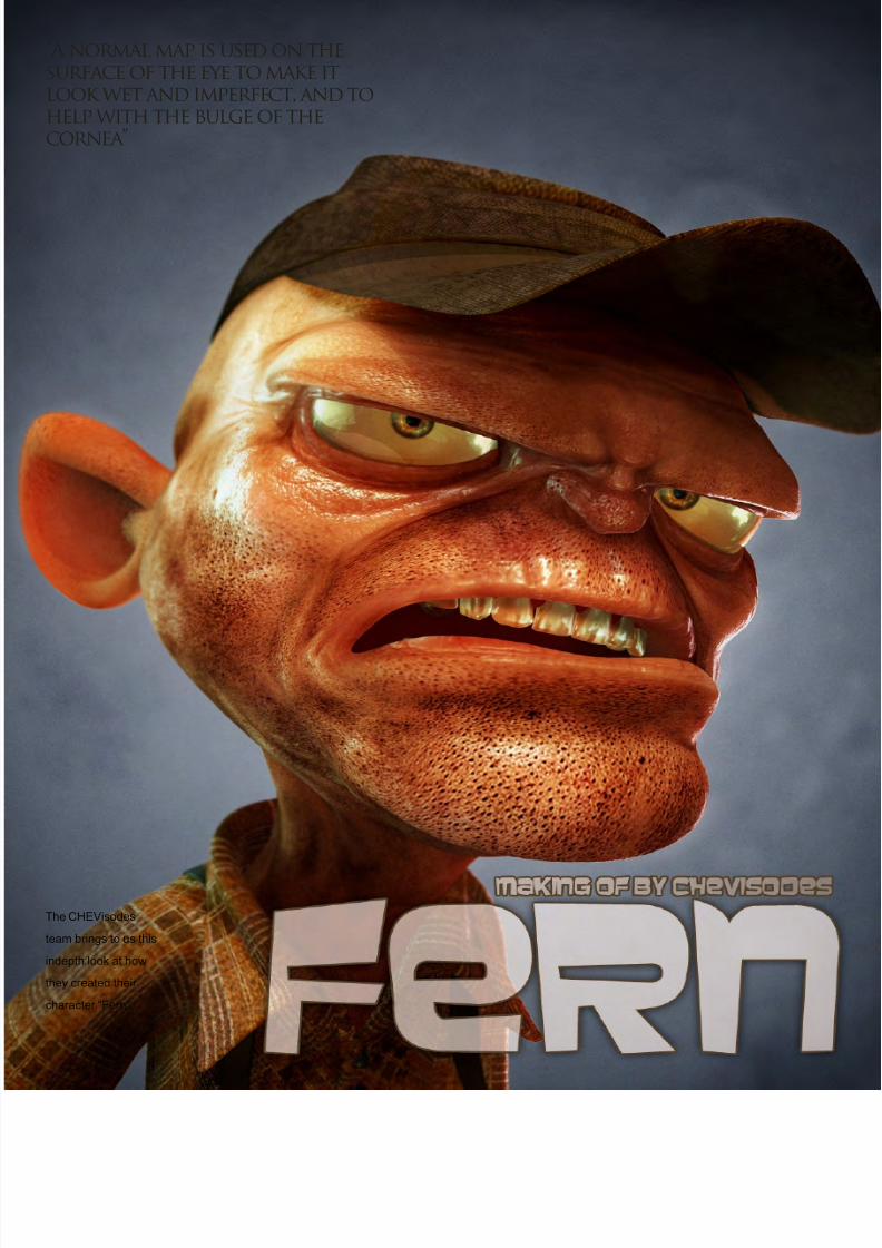
8/10/2019 3DCreative Magazine Issue 033 May 2008
http://slidepdf.com/reader/full/3dcreative-magazine-issue-033-may-2008 92/224
“A normal map is used on thesurface of the eye to make itlook wet and imperfect, and tohelp with the bulge of thecornea”
The CHEVisodes
team brings to us this
indepth look at how
they created their
character “Fern”.
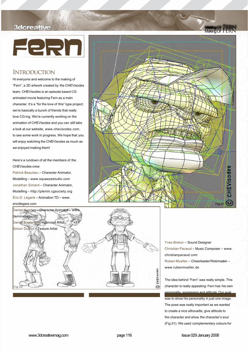
8/10/2019 3DCreative Magazine Issue 033 May 2008
http://slidepdf.com/reader/full/3dcreative-magazine-issue-033-may-2008 93/224
page 116www.3dcreativemag.com Issue 029 January 2008
Making Of Fern
IntroductionHi everyone and welcome to the making of
“Fern”, a 3D artwork created by the CHEVisodes
team. CHEVisodes is an episode based CG
animated movie featuring Fern as a main
character. It’s a “for the love of this” type project;
we’re basically a bunch of friends that really
love CG-ing. We’re currently working on the
animation of CHEVisodes and you can still take
a look at our website, www.chevisodes.com,
to see some work in progress. We hope that you
will enjoy watching the CHEVisodes as much as
we enjoyed making them!
Here’s a rundown of all the members of the
CHEVisodes crew:
Patrick Beaulieu – Character Animator,
Modelling – www.squeezestudio.com
Jonathan Simard – Character Animator,
Modelling – http://pikmin.cgsociety.org
Éric D. Légaré – Animation TD – www.
ericdlegare.com
Daniel Huertas – Character Animator – www.
danimating.com
Daniel Boulanger – Concept Artist
Simon Dubuc – Texture Artist
Yves Breton – Sound Designer
Christian Pacaud – Music Composer – www.
christianpacaud.com
Ruben Mueller – Cheerleader/Webmaster –
www.rubenmueller.de
The idea behind “Fern” was really simple. This
character is really appealing: Fern has his own
personality, expression and attitude. Our goal
was to show his personality in just one image.
The pose was really important as we wanted
to create a nice silhouette, give attitude to
the character and show the character’s soul
(Fig.01). We used complementary colours for
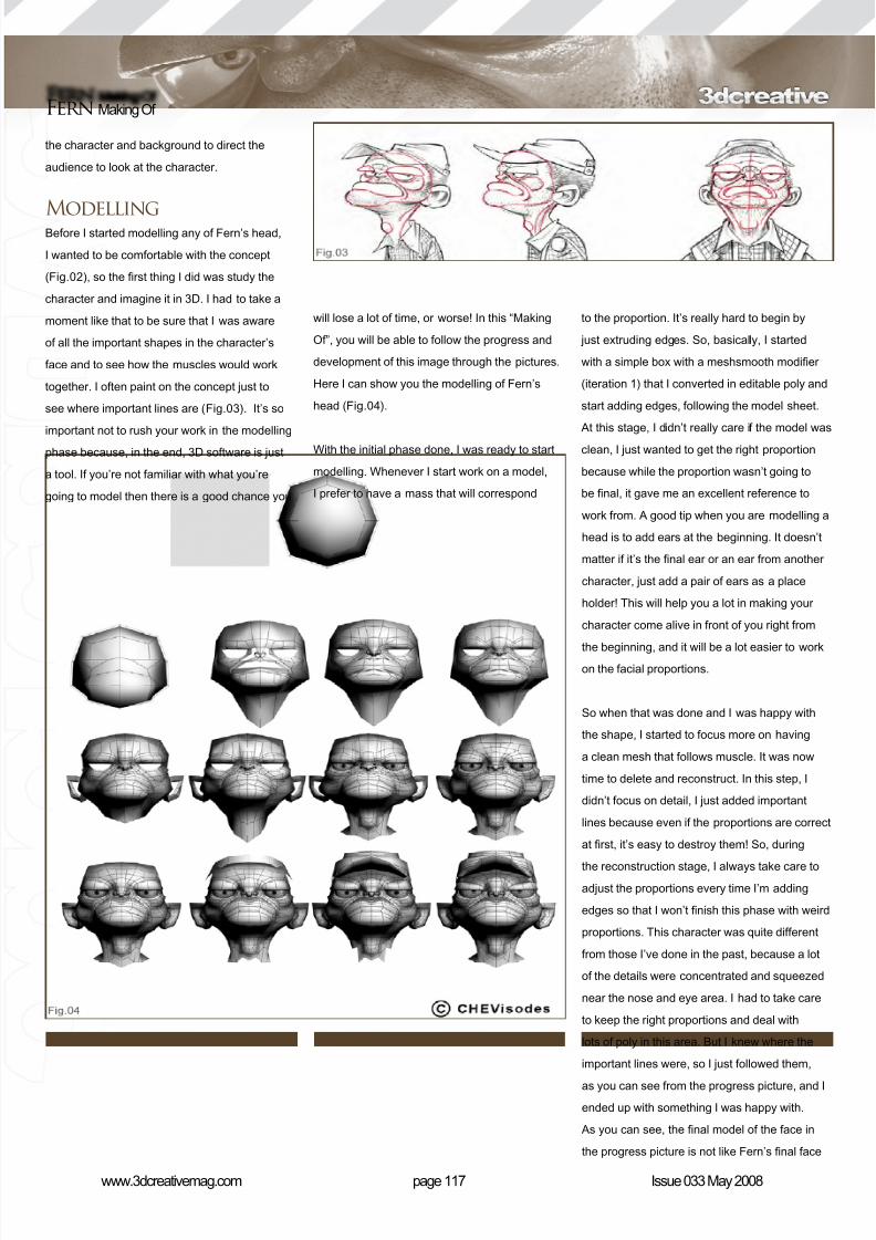
8/10/2019 3DCreative Magazine Issue 033 May 2008
http://slidepdf.com/reader/full/3dcreative-magazine-issue-033-may-2008 94/224
page 117www.3dcreativemag.com Issue 033 May 2008
Fern Making Of
the character and background to direct the
audience to look at the character.
ModellingBefore I started modelling any of Fern’s head,
I wanted to be comfortable with the concept
(Fig.02), so the rst thing I did was study the
character and imagine it in 3D. I had to take a
moment like that to be sure that I was aware
of all the important shapes in the character’s
face and to see how the muscles would work
together. I often paint on the concept just to
see where important lines are (Fig.03). It’s so
important not to rush your work in the modellingphase because, in the end, 3D software is just
a tool. If you’re not familiar with what you’re
going to model then there is a good chance you
will lose a lot of time, or worse! In this “Making
Of”, you will be able to follow the progress and
development of this image through the pictures.
Here I can show you the modelling of Fern’s
head (Fig.04).
With the initial phase done, I was ready to start
modelling. Whenever I start work on a model,
I prefer to have a mass that will correspond
to the proportion. It’s really hard to begin by
just extruding edges. So, basically, I started
with a simple box with a meshsmooth modier
(iteration 1) that I converted in editable poly and
start adding edges, following the model sheet.
At this stage, I didn’t really care if the model was
clean, I just wanted to get the right proportion
because while the proportion wasn’t going to
be nal, it gave me an excellent reference to
work from. A good tip when you are modelling a
head is to add ears at the beginning. It doesn’t
matter if it’s the nal ear or an ear from another
character, just add a pair of ears as a place
holder! This will help you a lot in making your
character come alive in front of you right from
the beginning, and it will be a lot easier to workon the facial proportions.
So when that was done and I was happy with
the shape, I started to focus more on having
a clean mesh that follows muscle. It was now
time to delete and reconstruct. In this step, I
didn’t focus on detail, I just added important
lines because even if the proportions are correct
at rst, it’s easy to destroy them! So, during
the reconstruction stage, I always take care toadjust the proportions every time I’m adding
edges so that I won’t nish this phase with weird
proportions. This character was quite different
from those I’ve done in the past, because a lot
of the details were concentrated and squeezed
near the nose and eye area. I had to take care
to keep the right proportions and deal with
lots of poly in this area. But I knew where the
important lines were, so I just followed them,
as you can see from the progress picture, and I
ended up with something I was happy with.
As you can see, the nal model of the face in
the progress picture is not like Fern’s nal face
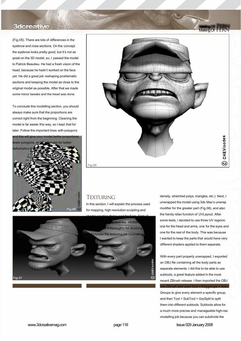
8/10/2019 3DCreative Magazine Issue 033 May 2008
http://slidepdf.com/reader/full/3dcreative-magazine-issue-033-may-2008 95/224
page 118www.3dcreativemag.com Issue 029 January 2008
Making Of Fern
(Fig.05). There are lots of differences in the
eyebrow and nose sections. On the concept,
the eyebrow looks pretty good, but it’s not as
great on the 3D model, so, I passed the modelto Patrick Beaulieu. He had a fresh vision of the
head, because he hadn’t worked on the face
yet. He did a great job reshaping problematic
sections and keeping the model as close to the
original model as possible. After that we made
some minor tweaks and the head was done.
To conclude this modelling section, you should
always make sure that the proportions are
correct right from the beginning. Cleaning themodel is far easier this way, so I kept that for
later. Follow the important lines with polygons
and this will give your model better proportions,
fewer polygons, and it will make for better
deformation for animation.
TexturingIn this section, I will explain the process used
for mapping, high resolution sculpting and
shader creation that I used for Fern. First of
all, I took the model from our modelling team
and examined it thoroughly for anything that
might hinder the texturing job (uneven polygon
density, stretched polys, triangles, etc.). Next, I
unwrapped the model using 3ds Max’s unwrap
modier for the greater part (Fig.06), and also
the handy relax function of UVLayout. After
some tests, I decided to use three UV regions:
one for the head and arms, one for the eyes and
one for the rest of the body. This was because
I wanted to keep the parts that would have verydifferent shaders applied to them separate.
With every part properly unwrapped, I exported
an OBJ le containing all the body parts as
separate elements. I did this to be able to use
subtools, a great feature added in the most
recent ZBrush release. I then imported the OBJ
into ZBrush and used Tool > Polygroups > Auto
Groups to give every element a specic group,
and then Tool > SubTool > GrpSplit to split
them into different subtools. Subtools allow for
a much more precise and manageable high-res
modelling job because you can subdivide the
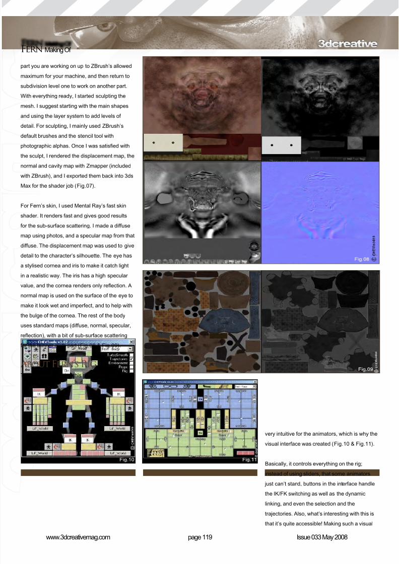
8/10/2019 3DCreative Magazine Issue 033 May 2008
http://slidepdf.com/reader/full/3dcreative-magazine-issue-033-may-2008 96/224
page 119www.3dcreativemag.com Issue 033 May 2008
Fern Making Of
part you are working on up to ZBrush’s allowed
maximum for your machine, and then return to
subdivision level one to work on another part.
With everything ready, I started sculpting themesh. I suggest starting with the main shapes
and using the layer system to add levels of
detail. For sculpting, I mainly used ZBrush’s
default brushes and the stencil tool with
photographic alphas. Once I was satised with
the sculpt, I rendered the displacement map, the
normal and cavity map with Zmapper (included
with ZBrush), and I exported them back into 3ds
Max for the shader job (Fig.07).
For Fern’s skin, I used Mental Ray’s fast skin
shader. It renders fast and gives good results
for the sub-surface scattering. I made a diffuse
map using photos, and a specular map from that
diffuse. The displacement map was used to give
detail to the character’s silhouette. The eye has
a stylised cornea and iris to make it catch light
in a realistic way. The iris has a high specular
value, and the cornea renders only reection. A
normal map is used on the surface of the eye tomake it look wet and imperfect, and to help with
the bulge of the cornea. The rest of the body
uses standard maps (diffuse, normal, specular,
reection), with a bit of sub-surface scattering
for the thinner cloth part (Fig.08 & Fig.09).
About Fern’s RigThe main idea behind this rig was to make it
very intuitive for the animators, which is why the
visual interface was created (Fig.10 & Fig.11).
Basically, it controls everything on the rig;
instead of using sliders, that some animators
just can’t stand, buttons in the interface handle
the IK/FK switching as well as the dynamic
linking, and even the selection and the
trajectories. Also, what’s interesting with this is
that it’s quite accessible! Making such a visual
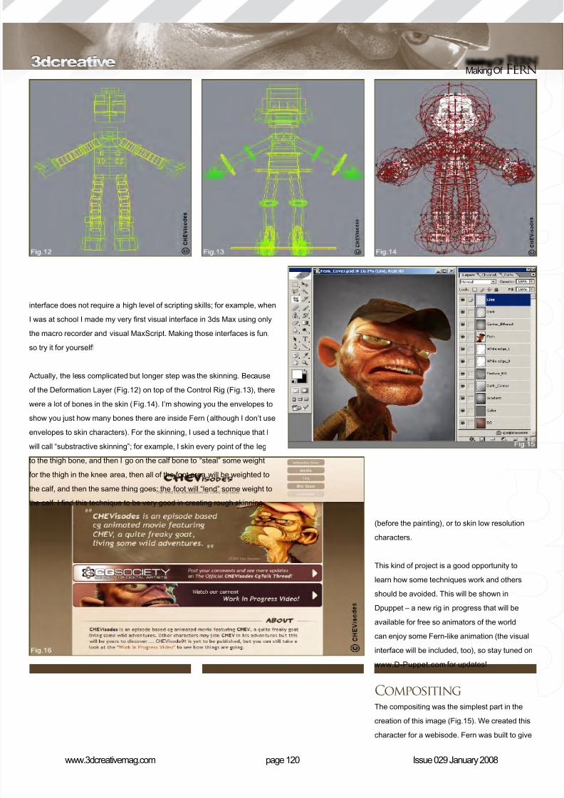
8/10/2019 3DCreative Magazine Issue 033 May 2008
http://slidepdf.com/reader/full/3dcreative-magazine-issue-033-may-2008 97/224
page 120www.3dcreativemag.com Issue 029 January 2008
Making Of Fern
interface does not require a high level of scripting skills; for example, when
I was at school I made my very rst visual interface in 3ds Max using only
the macro recorder and visual MaxScript. Making those interfaces is fun,
so try it for yourself!
Actually, the less complicated but longer step was the skinning. Because
of the Deformation Layer (Fig.12) on top of the Control Rig (Fig.13), there
were a lot of bones in the skin (Fig.14). I’m showing you the envelopes to
show you just how many bones there are inside Fern (although I don’t useenvelopes to skin characters). For the skinning, I used a technique that I
will call “substractive skinning”; for example, I skin every point of the leg
to the thigh bone, and then I go on the calf bone to “steal” some weight
for the thigh in the knee area, then all of the foot area will be weighted to
the calf, and then the same thing goes: the foot will “lend” some weight to
the calf. I nd this technique to be very good in creating rough skinning
(before the painting), or to skin low resolution
characters.
This kind of project is a good opportunity to
learn how some techniques work and others
should be avoided. This will be shown in
Dpuppet – a new rig in progress that will be
available for free so animators of the world
can enjoy some Fern-like animation (the visual
interface will be included, too), so stay tuned on
www.D-Puppet.com for updates!
CompositingThe compositing was the simplest part in the
creation of this image (Fig.15). We created this
character for a webisode. Fern was built to give
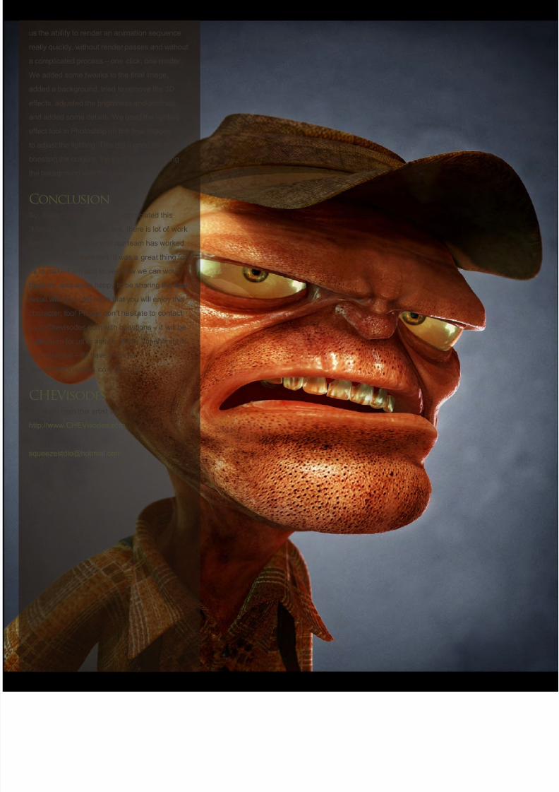
8/10/2019 3DCreative Magazine Issue 033 May 2008
http://slidepdf.com/reader/full/3dcreative-magazine-issue-033-may-2008 98/224
us the ability to render an animation sequence
really quickly, without render passes and without
a complicated process – one click, one render.
We added some tweaks to the nal image,
added a background, tried to remove the 3D
effects, adjusted the brightness and contrast
and added some details. We used the lighting
effect tool in Photoshop on the nal images
to adjust the lighting. This did a good job in
boosting the colours, the intensity, and mixing
the background with the character.
ConclusionSo, nally, I hope you have appreciated this
“Making Of”. As you can see, there is lot of work
behind this character and our team has worked
really hard to create him. It was a great thing for
us to make Fern and to see how we can work
together, and we’re happy to be sharing the nal
result with you. We hope that you will enjoy this
character, too! Please don’t hesitate to contact
us at Chevisodes.com with questions – it will be
a pleasure for us to answer them! I’m entirely at
your disposal – if I have the time…
www.CHEVisodes.com (Fig.16)
CHEVisodesFor more from this artist visit:
http://www.CHEVisodes.com
Or contact:
8/10/2019 3DCreative Magazine Issue 033 May 2008
http://slidepdf.com/reader/full/3dcreative-magazine-issue-033-may-2008 99/224
The series will cover an in-depth and comprehensive guide to
modelling the amazing Bugatti Veyron car, from start to nish.
We will focus on the key techniques and stages involved in
building the chassis, as well as details such as the windows,
lights, vents, petrol caps, engine parts and so on. The series
will then move on to creating the wheels, including tyres
and hubcaps, before going on to building and incorporating
an interior, namely the dashboard and seating. This will be
followed by a section on creating and applying materials for
the numerous parts of the car, such as the paint work, chrome,
rubber and glass, before concluding with a tutorial devoted to
setting the scene for a nished render. The nal part will cover
the importance of a good lighting rig and light parameters, as
well as the importance of a camera and the integral part that the
rendering settings play in showcasing the model for a portfolio.
This series aims to offer a comprehensive guide for creating a
nished car to people who are new to this type of exercise, but
is not suitable for beginners who are not familiar with using 3D
software. The tutorials do not detail every single step of adding
individual edge loops and vertices, but they do endeavour to
outline each important stage and explain the crucial techniques
necessary to following the exercise.
The schedule is as follows:
Issue 029 January 2008
Modelling the Chassis - Basics
Issue 031 March 2008Modelling the Chassis - Details
Issue 032 April 2008
Wheels, Tyres & Rims
Issue 033 May 2008
Interior
Issue 034 June 2008
The Materials & Finishes
Issue 035 July 2008
Lighting Set up & Render
Enjoy ...
Bugatti Veyron car modelling series
www.the-blueprints.com
Blueprints are available here:
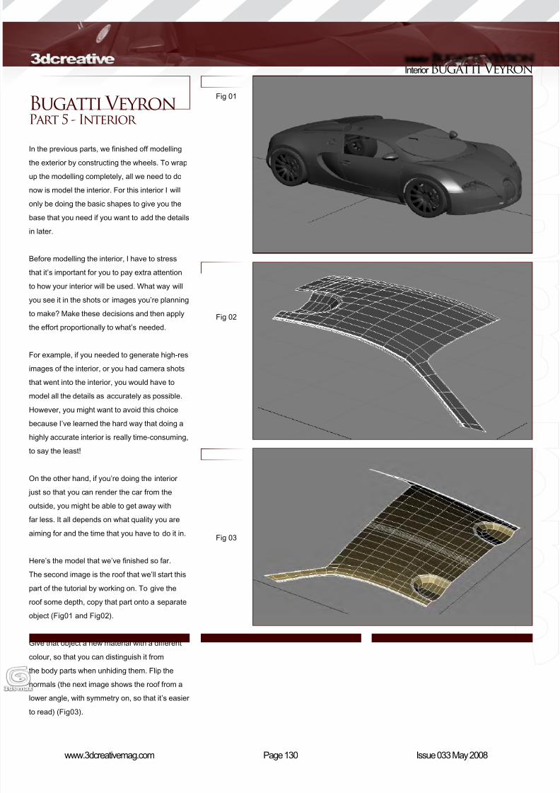
8/10/2019 3DCreative Magazine Issue 033 May 2008
http://slidepdf.com/reader/full/3dcreative-magazine-issue-033-may-2008 100/224
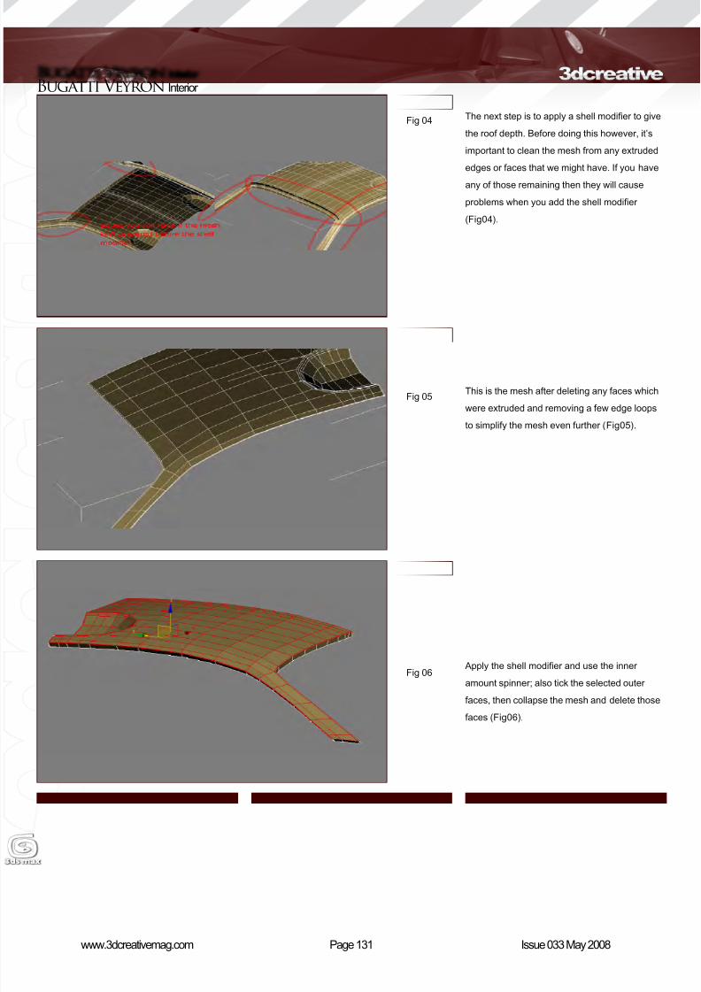
8/10/2019 3DCreative Magazine Issue 033 May 2008
http://slidepdf.com/reader/full/3dcreative-magazine-issue-033-may-2008 101/224
Page 131www.3dcreativemag.com Issue 033 May 2008
Bugatti Veyron Interior
Fig 04
Fig 05
Fig 06
The next step is to apply a shell modier to give
the roof depth. Before doing this however, it’s
important to clean the mesh from any extruded
edges or faces that we might have. If you have
any of those remaining then they will cause
problems when you add the shell modier
(Fig04).
This is the mesh after deleting any faces which
were extruded and removing a few edge loops
to simplify the mesh even further (Fig05).
Apply the shell modier and use the inner
amount spinner; also tick the selected outer
faces, then collapse the mesh and delete those
faces (Fig06).
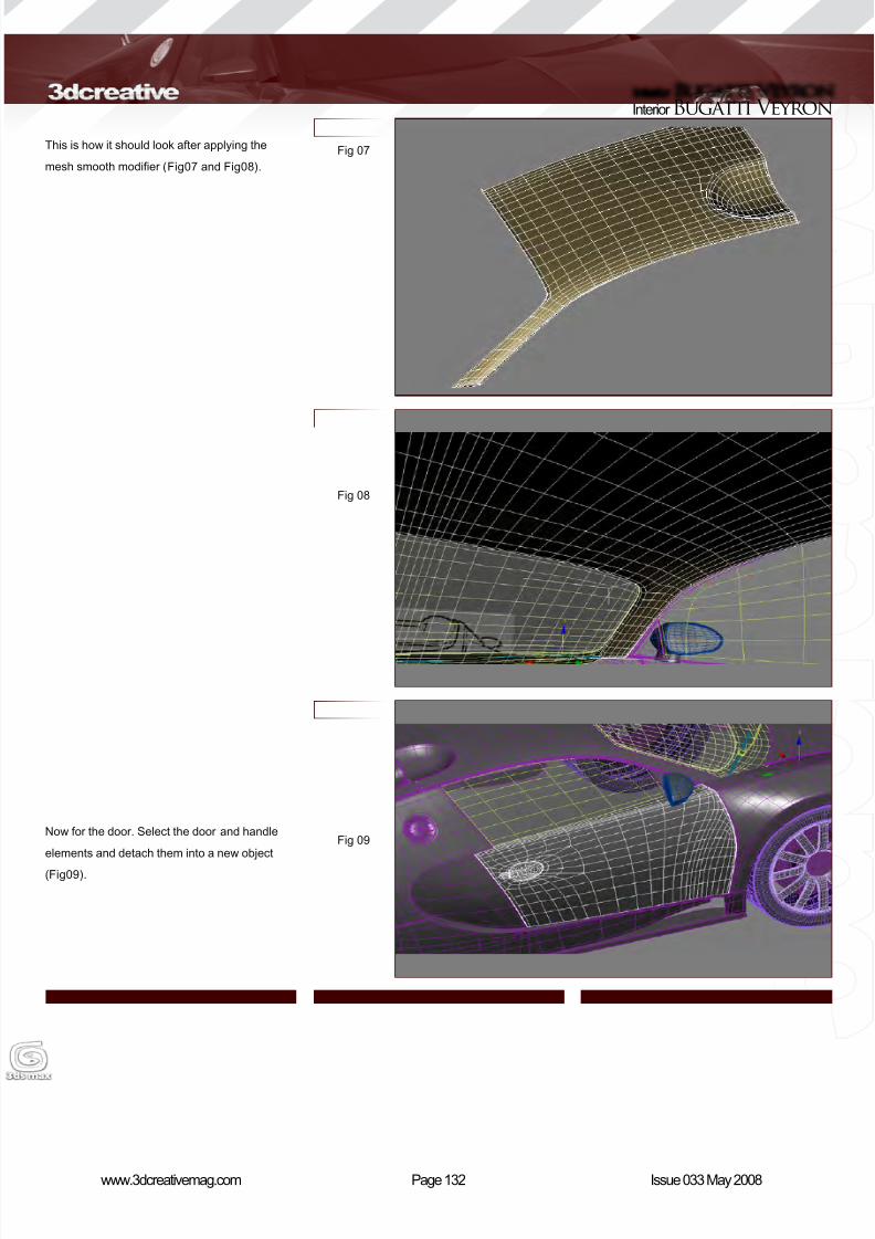
8/10/2019 3DCreative Magazine Issue 033 May 2008
http://slidepdf.com/reader/full/3dcreative-magazine-issue-033-may-2008 102/224
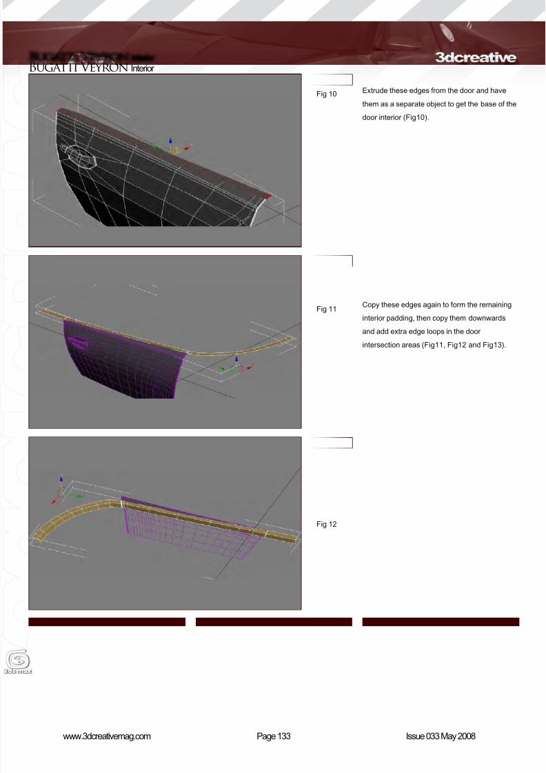
8/10/2019 3DCreative Magazine Issue 033 May 2008
http://slidepdf.com/reader/full/3dcreative-magazine-issue-033-may-2008 103/224
Page 133www.3dcreativemag.com Issue 033 May 2008
Bugatti Veyron Interior
Extrude these edges from the door and have
them as a separate object to get the base of the
door interior (Fig10).
Copy these edges again to form the remaining
interior padding, then copy them downwards
and add extra edge loops in the door
intersection areas (Fig11, Fig12 and Fig13).
Fig 10
Fig 11
Fig 12
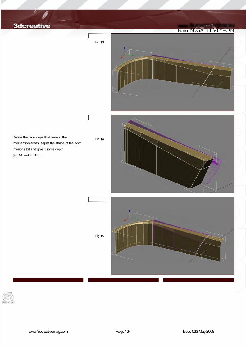
8/10/2019 3DCreative Magazine Issue 033 May 2008
http://slidepdf.com/reader/full/3dcreative-magazine-issue-033-may-2008 104/224
Page 134www.3dcreativemag.com Issue 033 May 2008
Interior Bugatti Veyron
Delete the face loops that were at the
intersection areas, adjust the shape of the door
interior a bit and give it some depth
(Fig14 and Fig15).
Fig 13
Fig 14
Fig 15
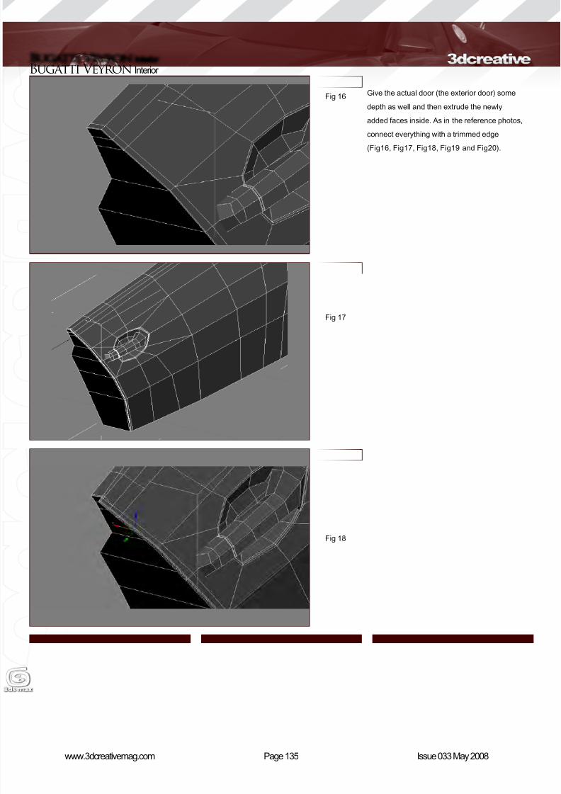
8/10/2019 3DCreative Magazine Issue 033 May 2008
http://slidepdf.com/reader/full/3dcreative-magazine-issue-033-may-2008 105/224
Page 135www.3dcreativemag.com Issue 033 May 2008
Bugatti Veyron Interior
Give the actual door (the exterior door) some
depth as well and then extrude the newly
added faces inside. As in the reference photos,
connect everything with a trimmed edge
(Fig16, Fig17, Fig18, Fig19 and Fig20).
Fig 16
Fig 17
Fig 18
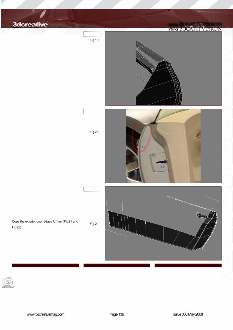
8/10/2019 3DCreative Magazine Issue 033 May 2008
http://slidepdf.com/reader/full/3dcreative-magazine-issue-033-may-2008 106/224
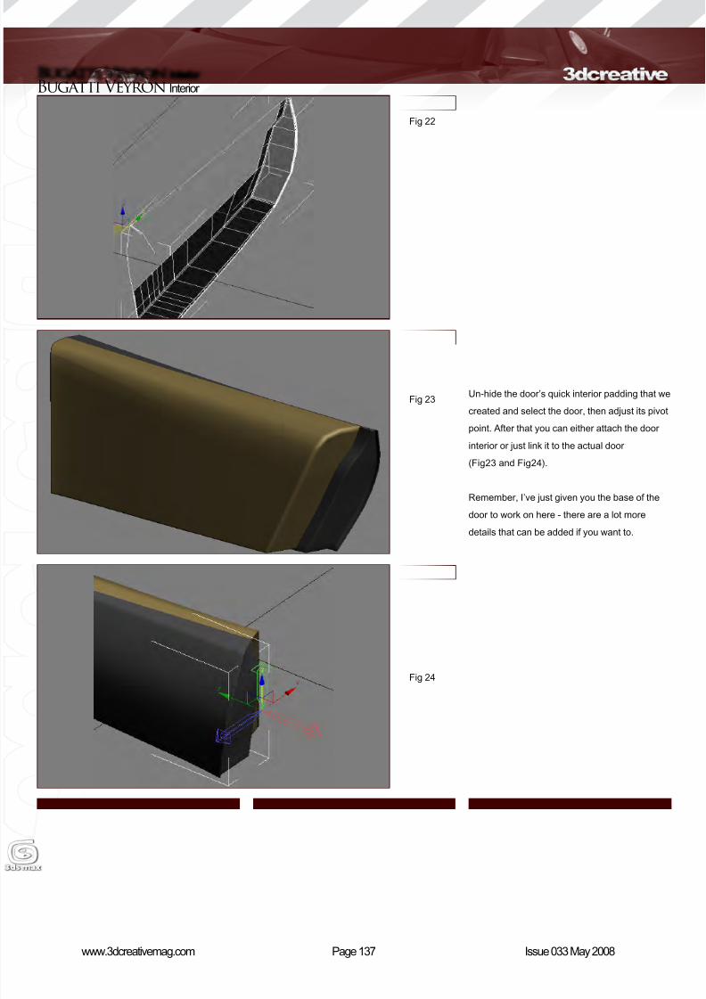
8/10/2019 3DCreative Magazine Issue 033 May 2008
http://slidepdf.com/reader/full/3dcreative-magazine-issue-033-may-2008 107/224
Page 137www.3dcreativemag.com Issue 033 May 2008
Bugatti Veyron Interior
Un-hide the door’s quick interior padding that we
created and select the door, then adjust its pivot
point. After that you can either attach the door
interior or just link it to the actual door
(Fig23 and Fig24).
Remember, I’ve just given you the base of the
door to work on here - there are a lot more
details that can be added if you want to.
Fig 22
Fig 23
Fig 24

8/10/2019 3DCreative Magazine Issue 033 May 2008
http://slidepdf.com/reader/full/3dcreative-magazine-issue-033-may-2008 108/224
Page 138www.3dcreativemag.com Issue 033 May 2008
Interior Bugatti Veyron
Next we can move onto the chairs. Luckily the
side blueprints we used have a simple drawing
for the chairs, which you can trace out. (As we
noted in the previous parts, blueprints aren’t
always 100% accurate and it’s always better
to double-check everything by looking at the
reference photos!) The process of modelling the
chairs is as shown in the images (Fig25, Fig26,
Fig27, Fig28, Fig29 and Fig30).
Fig 25
Fig 26
Fig 27
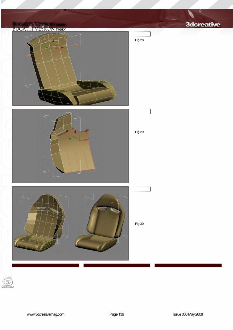
8/10/2019 3DCreative Magazine Issue 033 May 2008
http://slidepdf.com/reader/full/3dcreative-magazine-issue-033-may-2008 109/224
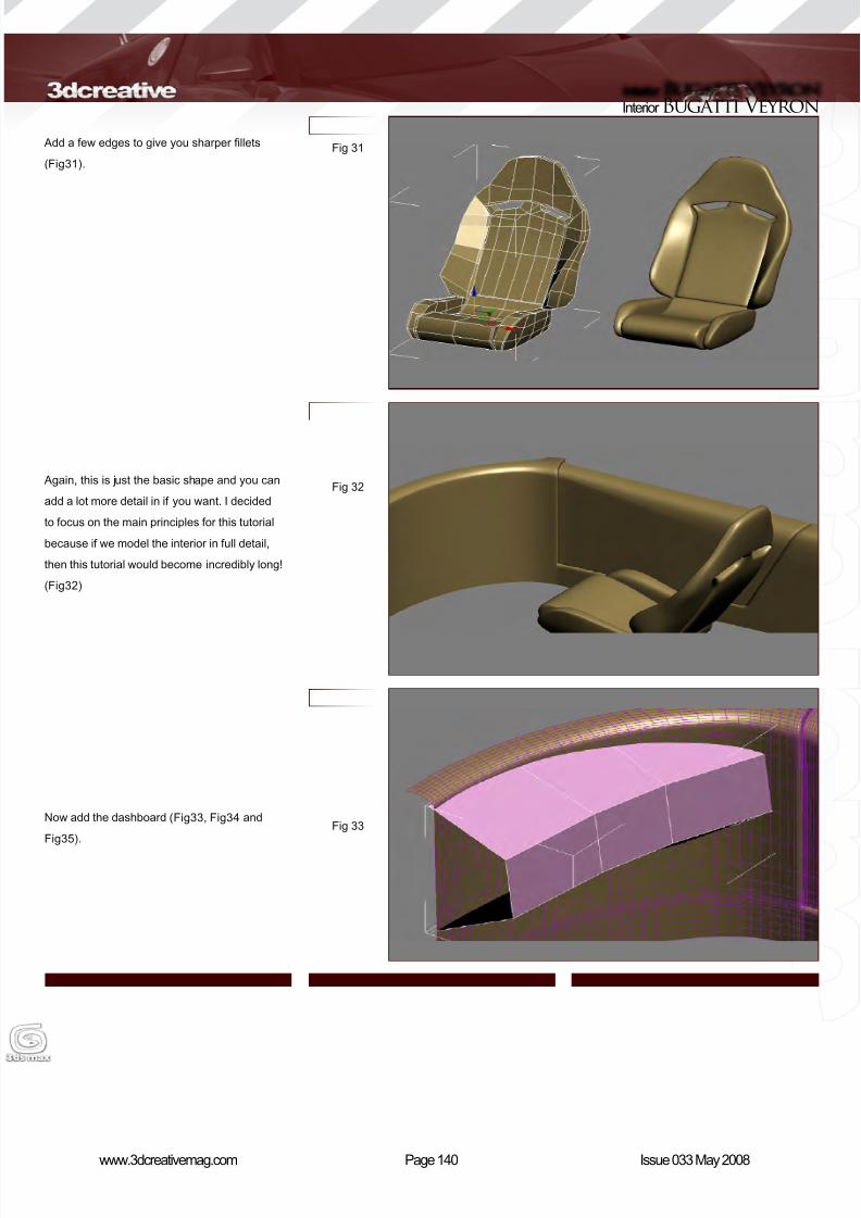
8/10/2019 3DCreative Magazine Issue 033 May 2008
http://slidepdf.com/reader/full/3dcreative-magazine-issue-033-may-2008 110/224
Page 140www.3dcreativemag.com Issue 033 May 2008
Interior Bugatti Veyron
Add a few edges to give you sharper llets
(Fig31).
Again, this is just the basic shape and you can
add a lot more detail in if you want. I decided
to focus on the main principles for this tutorial
because if we model the interior in full detail,
then this tutorial would become incredibly long!
(Fig32)
Now add the dashboard (Fig33, Fig34 and
Fig35).
Fig 31
Fig 32
Fig 33

8/10/2019 3DCreative Magazine Issue 033 May 2008
http://slidepdf.com/reader/full/3dcreative-magazine-issue-033-may-2008 111/224
Page 141www.3dcreativemag.com Issue 033 May 2008
Bugatti Veyron Interior
For the centre console, which holds the gear
knob and some of the air conditioning vents, use
the same method of placing reference objects
(as a cylinder or an extruded curve) to help you
decide where to place the polygon cuts. Then
extrude those polygons (Fig36 and Fig37).
Fig 34
Fig 35
Fig 36
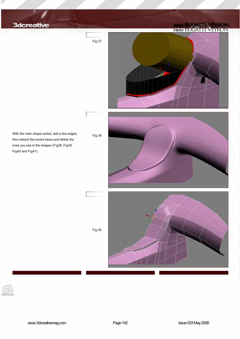
8/10/2019 3DCreative Magazine Issue 033 May 2008
http://slidepdf.com/reader/full/3dcreative-magazine-issue-033-may-2008 112/224
Page 142www.3dcreativemag.com Issue 033 May 2008
Interior Bugatti Veyron
With the main shape sorted, add a few edges,
then detach the centre faces and delete the
ones you see in the images (Fig38, Fig39,
Fig40 and Fig41).
Fig 37
Fig 38
Fig 39

8/10/2019 3DCreative Magazine Issue 033 May 2008
http://slidepdf.com/reader/full/3dcreative-magazine-issue-033-may-2008 113/224
Page 143www.3dcreativemag.com Issue 033 May 2008
Bugatti Veyron Interior
For the dashboard instruments and dial covers,
create a quick sphere, then delete some of the
faces and add a shell modier. If you want, you
can then add quick dials by modelling them or
using a quick texture if you’re in a hurry. (Fig42
and Fig43).
Fig 40
Fig 41
Fig 42
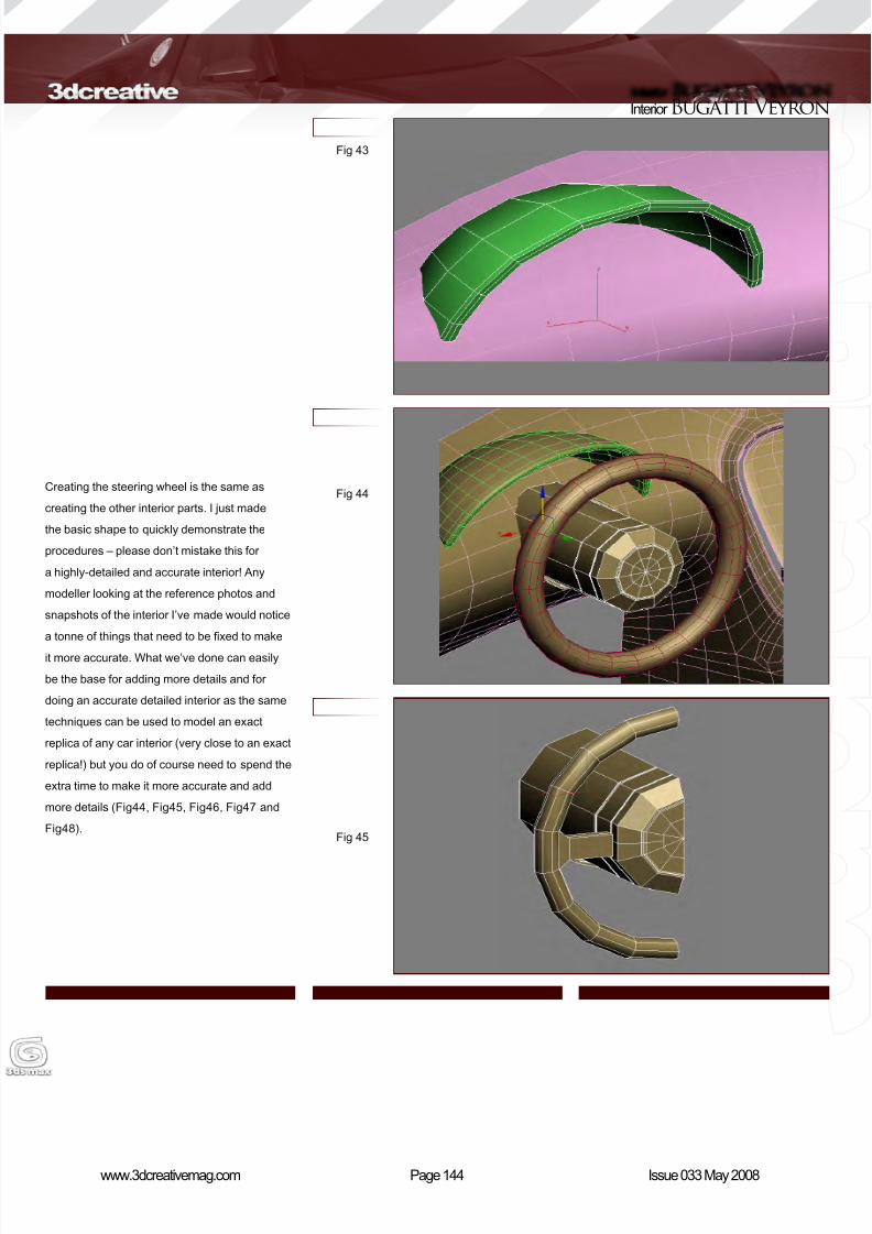
8/10/2019 3DCreative Magazine Issue 033 May 2008
http://slidepdf.com/reader/full/3dcreative-magazine-issue-033-may-2008 114/224
Page 144www.3dcreativemag.com Issue 033 May 2008
Interior Bugatti Veyron
Creating the steering wheel is the same as
creating the other interior parts. I just made
the basic shape to quickly demonstrate the
procedures – please don’t mistake this for
a highly-detailed and accurate interior! Any
modeller looking at the reference photos and
snapshots of the interior I’ve made would notice
a tonne of things that need to be xed to make
it more accurate. What we’ve done can easily
be the base for adding more details and for
doing an accurate detailed interior as the same
techniques can be used to model an exact
replica of any car interior (very close to an exact
replica!) but you do of course need to spend the
extra time to make it more accurate and add
more details (Fig44, Fig45, Fig46, Fig47 and
Fig48).
Fig 43
Fig 44
Fig 45
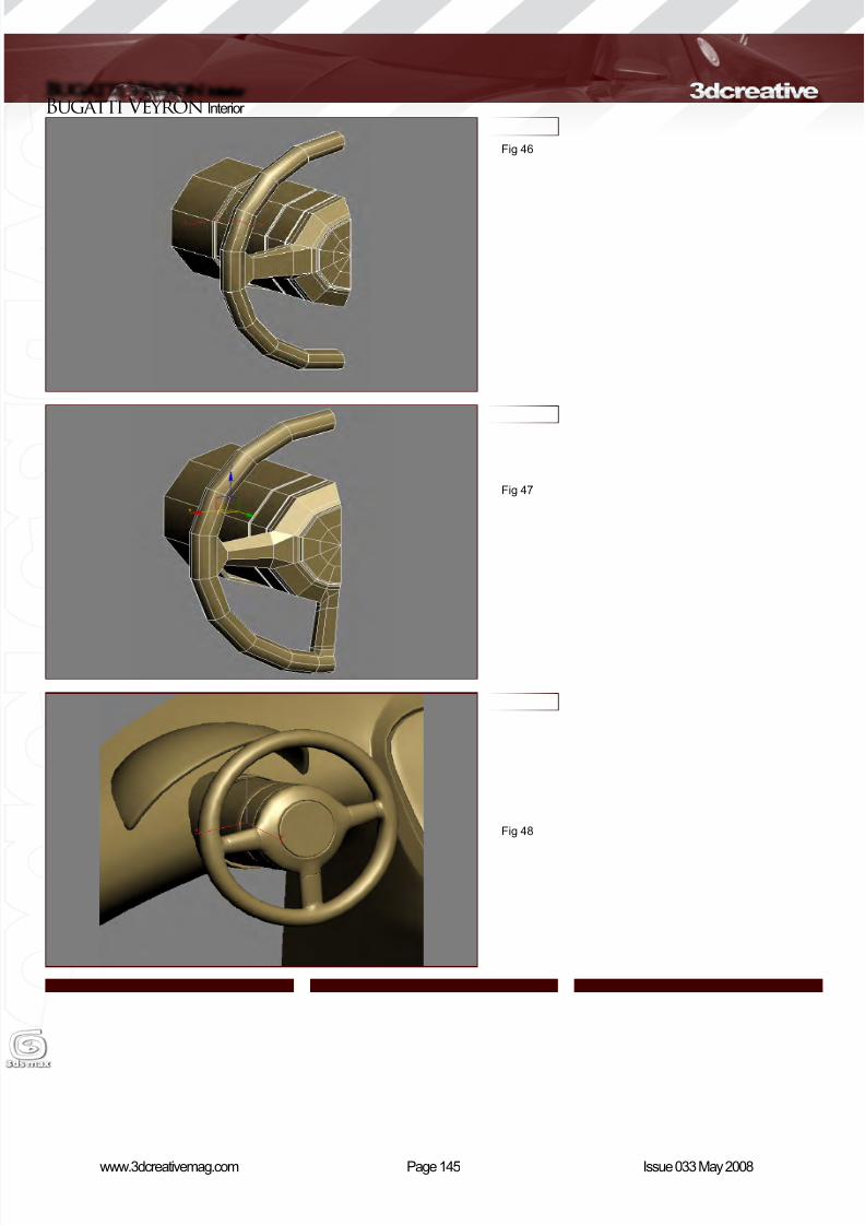
8/10/2019 3DCreative Magazine Issue 033 May 2008
http://slidepdf.com/reader/full/3dcreative-magazine-issue-033-may-2008 115/224
Page 145www.3dcreativemag.com Issue 033 May 2008
Bugatti Veyron Interior
Fig 46
Fig 47
Fig 48

8/10/2019 3DCreative Magazine Issue 033 May 2008
http://slidepdf.com/reader/full/3dcreative-magazine-issue-033-may-2008 116/224
Page 146www.3dcreativemag.com Issue 033 May 2008
Interior Bugatti Veyron
Finally I quickly modelled and added the gear
knob (Fig49, Fig50, Fig51, Fig52 and Fig53).
Fig 49
Fig 50
Fig 51
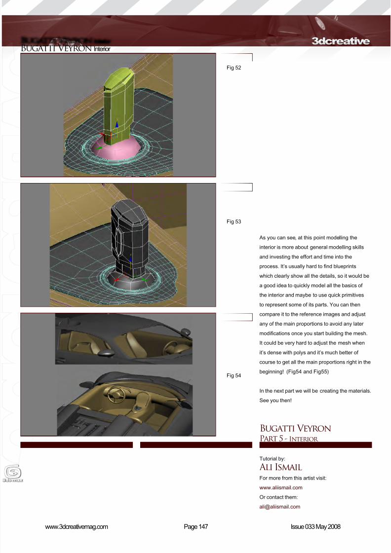
8/10/2019 3DCreative Magazine Issue 033 May 2008
http://slidepdf.com/reader/full/3dcreative-magazine-issue-033-may-2008 117/224
Page 147www.3dcreativemag.com Issue 033 May 2008
Bugatti Veyron Interior
As you can see, at this point modelling the
interior is more about general modelling skills
and investing the effort and time into the
process. It’s usually hard to nd blueprints
which clearly show all the details, so it would be
a good idea to quickly model all the basics of
the interior and maybe to use quick primitives
to represent some of its parts. You can then
compare it to the reference images and adjust
any of the main proportions to avoid any later
modications once you start building the mesh.
It could be very hard to adjust the mesh when
it’s dense with polys and it’s much better of
course to get all the main proportions right in the
beginning! (Fig54 and Fig55)
In the next part we will be creating the materials.
See you then!
Bugatti VeyronPart 5 - Interior
Tutorial by:
Ali IsmailFor more from this artist visit:
www.aliismail.com
Or contact them:
Fig 52
Fig 53
Fig 54
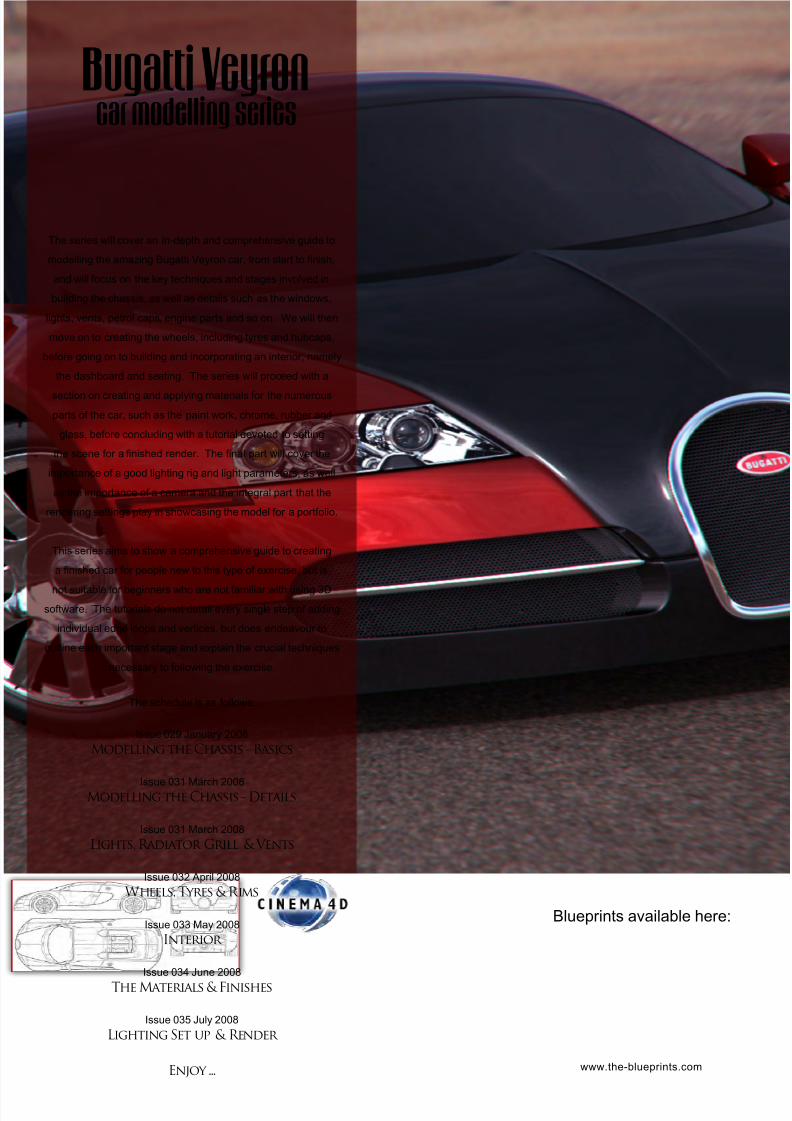
8/10/2019 3DCreative Magazine Issue 033 May 2008
http://slidepdf.com/reader/full/3dcreative-magazine-issue-033-may-2008 118/224
The series will cover an in-depth and comprehensive guide to
modelling the amazing Bugatti Veyron car, from start to nish,
and will focus on the key techniques and stages involved in
building the chassis, as well as details such as the windows,
lights, vents, petrol caps, engine parts and so on. We will then
move on to creating the wheels, including tyres and hubcaps,
before going on to building and incorporating an interior, namely
the dashboard and seating. The series will proceed with a
section on creating and applying materials for the numerous
parts of the car, such as the paint work, chrome, rubber and
glass, before concluding with a tutorial devoted to setting
the scene for a nished render. The nal part will cover the
importance of a good lighting rig and light parameters, as well
as the importance of a camera and the integral part that the
rendering settings play in showcasing the model for a portfolio.
This series aims to show a comprehensive guide to creating
a nished car for people new to this type of exercise, but is
not suitable for beginners who are not familiar with using 3D
software. The tutorials do not detail every single step of adding
individual edge loops and vertices, but does endeavour to
outline each important stage and explain the crucial techniques
necessary to following the exercise.
The schedule is as follows:
Issue 029 January 2008
Modelling the Chassis - Basics
Issue 031 March 2008Modelling the Chassis - Details
Issue 031 March 2008
Lights, Radiator Grill & Vents
Issue 032 April 2008
Wheels, Tyres & Rims
Issue 033 May 2008
Interior
Issue 034 June 2008
The Materials & Finishes
Issue 035 July 2008
Lighting Set up & Render
Enjoy ...
Bugatti Veyron car modelling series
www.the-blueprints.com
Blueprints available here:
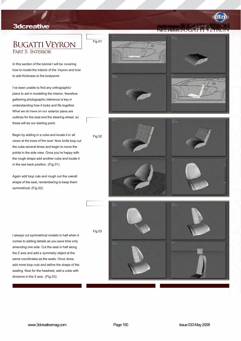
8/10/2019 3DCreative Magazine Issue 033 May 2008
http://slidepdf.com/reader/full/3dcreative-magazine-issue-033-may-2008 119/224
Page 150www.3dcreativemag.com Issue 033 May 2008
Part 5: InteriorsBUGATTI VEYRON
Fig 01
Fig 02
Fig 03
Bugatti VeyronPart 5: Interior
In this section of the tutorial I will be covering
how to model the interior of the Veyron and how
to add thickness to the bodywork.
I’ve been unable to nd any orthographic/
plans to aid in modelling the interior, therefore
gathering photographic reference is key in
understanding how it looks and ts together.
What we do have on our exterior plans are
outlines for the seat and the steering wheel, so
these will be our starting point.
Begin by adding in a cube and locate it in all
views at the base of the seat. Now knife loop cut
the cube several times and begin to move the
points in the side view. Once you’re happy with
the rough shape add another cube and locate it
in the see back position. (Fig.01)
Again add loop cuts and rough out the overall
shape of the seat, remembering to keep them
symmetrical. (Fig.02)
I always cut symmetrical models in half when it
comes to adding details as you save time only
amending one side. Cut the seat in half along
the Z axis and add a symmetry object at the
same coordinates as the seats. Once done,
add more loop cuts and dene the shape of the
seating. Now for the headrest, add a cube with
divisions in the X axis. (Fig.03)
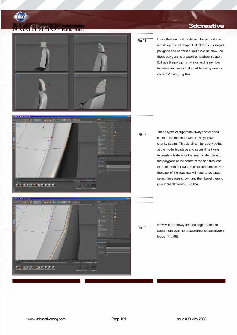
8/10/2019 3DCreative Magazine Issue 033 May 2008
http://slidepdf.com/reader/full/3dcreative-magazine-issue-033-may-2008 120/224
Page 151www.3dcreativemag.com Issue 033 May 2008
BUGATTI VEYRON Part 5: Interiors
Fig 04
Fig 05
Fig 06
Halve the headrest model and begin to shape it
into its cylindrical shape. Select the outer ring of
polygons and perform a split function. Now use
these polygons to create the headrest support.
Extrude the polygons inwards and remember
to delete and faces that straddle the symmetry
objects Z axis. (Fig.04)
These types of supercars always have hand
stitched leather seats which always have
chunky seams. This detail can be easily added
at the modelling stage and saves time trying
to create a texture for the seams later. Select
the polygons at the centre of the headrest and
extrude them out twice in small increments. For
the back of the seat you will need to loop/path
select the edges shown and then bevel them to
give more denition. (Fig.05)
Now with the newly created edges selected,
bevel them again to create three, close polygon
loops. (Fig.06)
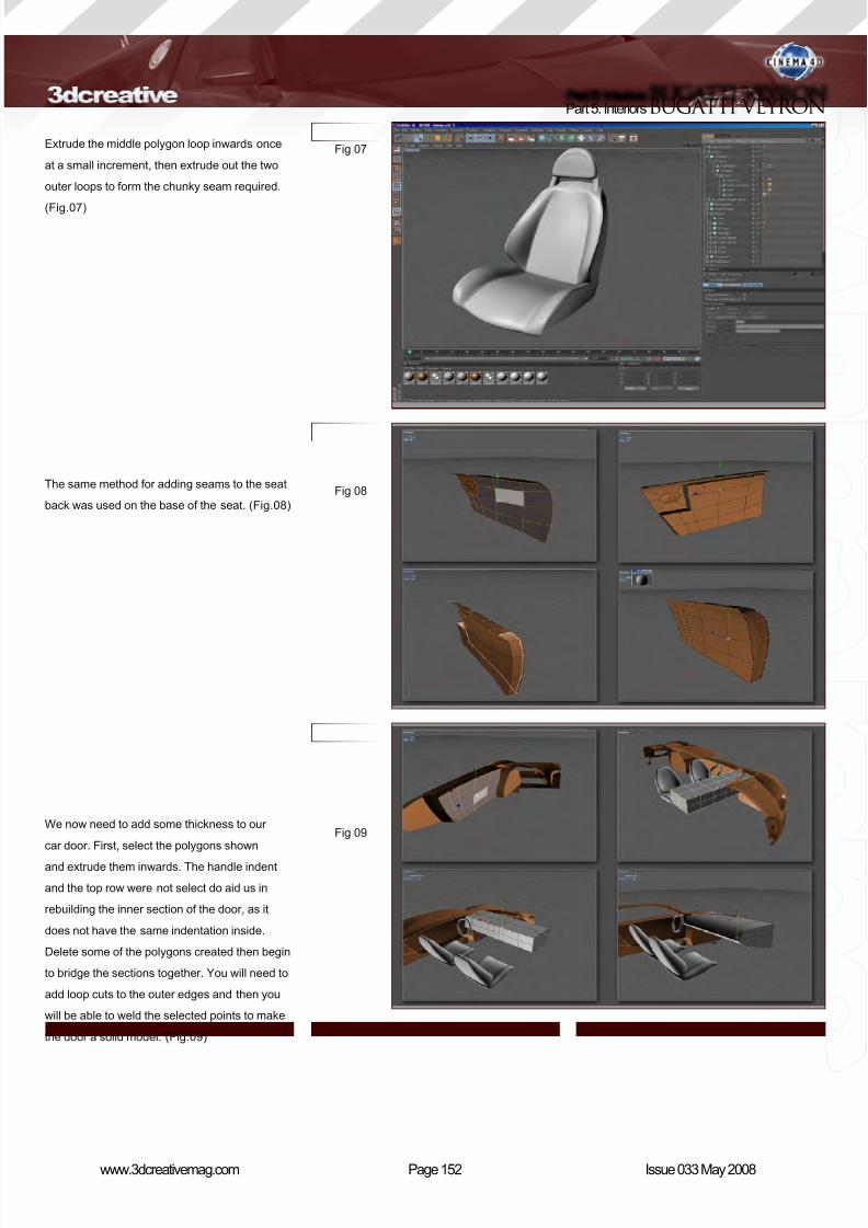
8/10/2019 3DCreative Magazine Issue 033 May 2008
http://slidepdf.com/reader/full/3dcreative-magazine-issue-033-may-2008 121/224
Page 152www.3dcreativemag.com Issue 033 May 2008
Part 5: InteriorsBUGATTI VEYRON
Extrude the middle polygon loop inwards once
at a small increment, then extrude out the two
outer loops to form the chunky seam required.
(Fig.07)
The same method for adding seams to the seat
back was used on the base of the seat. (Fig.08)
We now need to add some thickness to our
car door. First, select the polygons shown
and extrude them inwards. The handle indent
and the top row were not select do aid us in
rebuilding the inner section of the door, as it
does not have the same indentation inside.
Delete some of the polygons created then begin
to bridge the sections together. You will need to
add loop cuts to the outer edges and then you
will be able to weld the selected points to make
the door a solid model. (Fig.09)
Fig 07
Fig 08
Fig 09
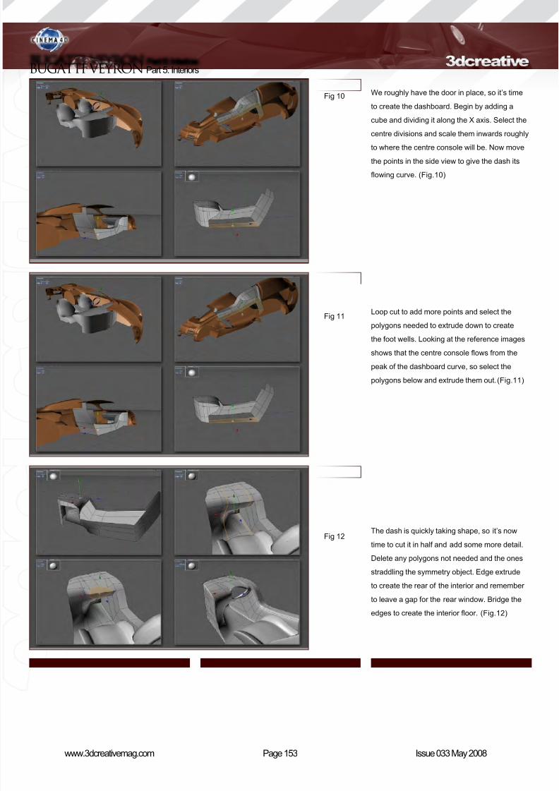
8/10/2019 3DCreative Magazine Issue 033 May 2008
http://slidepdf.com/reader/full/3dcreative-magazine-issue-033-may-2008 122/224
Page 153www.3dcreativemag.com Issue 033 May 2008
BUGATTI VEYRON Part 5: Interiors
We roughly have the door in place, so it’s time
to create the dashboard. Begin by adding a
cube and dividing it along the X axis. Select the
centre divisions and scale them inwards roughly
to where the centre console will be. Now move
the points in the side view to give the dash its
owing curve. (Fig.10)
Loop cut to add more points and select the
polygons needed to extrude down to create
the foot wells. Looking at the reference images
shows that the centre console ows from the
peak of the dashboard curve, so select the
polygons below and extrude them out.(Fig.11)
The dash is quickly taking shape, so it’s now
time to cut it in half and add some more detail.
Delete any polygons not needed and the ones
straddling the symmetry object. Edge extrude
to create the rear of the interior and remember
to leave a gap for the rear window. Bridge the
edges to create the interior oor. (Fig.12)
Fig 10
Fig 11
Fig 12
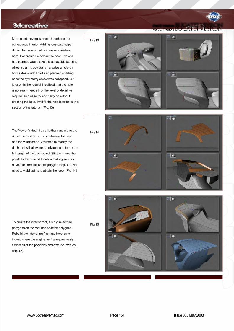
8/10/2019 3DCreative Magazine Issue 033 May 2008
http://slidepdf.com/reader/full/3dcreative-magazine-issue-033-may-2008 123/224
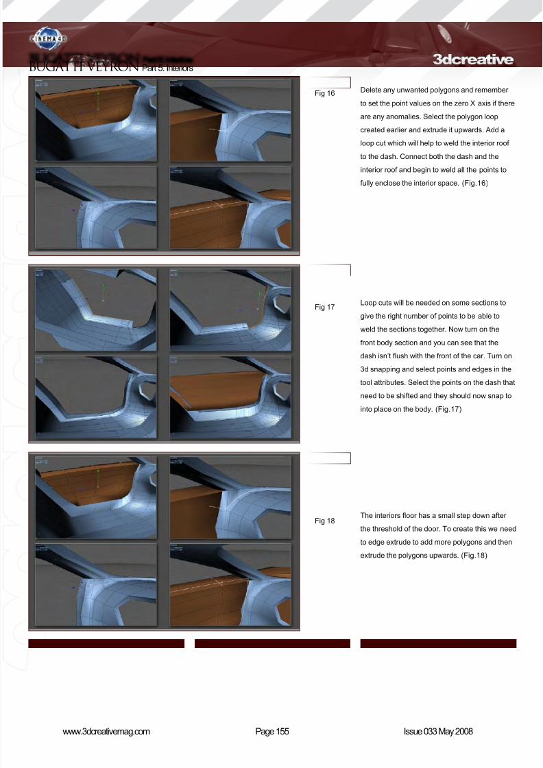
8/10/2019 3DCreative Magazine Issue 033 May 2008
http://slidepdf.com/reader/full/3dcreative-magazine-issue-033-may-2008 124/224
Page 155www.3dcreativemag.com Issue 033 May 2008
BUGATTI VEYRON Part 5: Interiors
Delete any unwanted polygons and remember
to set the point values on the zero X axis if there
are any anomalies. Select the polygon loop
created earlier and extrude it upwards. Add a
loop cut which will help to weld the interior roof
to the dash. Connect both the dash and the
interior roof and begin to weld all the points to
fully enclose the interior space. (Fig.16)
Loop cuts will be needed on some sections to
give the right number of points to be able to
weld the sections together. Now turn on the
front body section and you can see that the
dash isn’t ush with the front of the car. Turn on
3d snapping and select points and edges in the
tool attributes. Select the points on the dash that
need to be shifted and they should now snap to
into place on the body. (Fig.17)
The interiors oor has a small step down after
the threshold of the door. To create this we need
to edge extrude to add more polygons and then
extrude the polygons upwards. (Fig.18)
Fig 16
Fig 17
Fig 18

8/10/2019 3DCreative Magazine Issue 033 May 2008
http://slidepdf.com/reader/full/3dcreative-magazine-issue-033-may-2008 125/224
Page 156www.3dcreativemag.com Issue 033 May 2008
Part 5: InteriorsBUGATTI VEYRON
We’ve created the recess for the door, but now
we need to use the 3d snapping again to make
sure the interior and the door follow the same
line and have a uniform seam/split-line. The lip
that runs around the dash also ows into the
door panel so time is needed to move the points
to make sure that everything ows together.
(Fig.19)
The door is not one solid shape - it also has
contours on the front and back which are hidden
when the doors are closed. Delete the polygons
and then select the outer dangling polygons.
Extrude these polygons and weld them in place
on the next row of edges. (Fig.20)
Loop cuts will add denition, but make sure the
outer section of the door (body side) does not
have any unsightly seams and that it still ows
with the rest of the cars body. The inner panels
are simply selected polygons extruded inwards
and I’ve added an eight sided cylinder for the
handle. Squash the cylinder in the X axis to an
oval cylinder, then extrude out the top inner
section to create the return where the latch
mechanism will sit. (Fig.21)
Fig 19
Fig 20
Fig 21
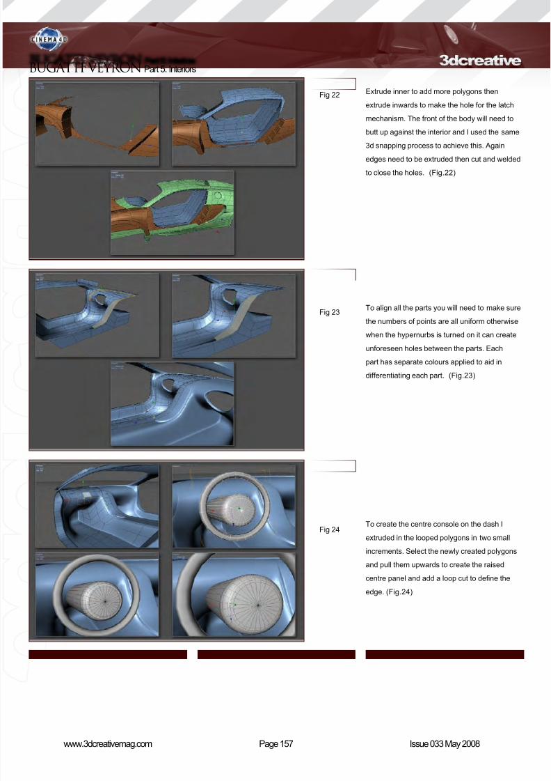
8/10/2019 3DCreative Magazine Issue 033 May 2008
http://slidepdf.com/reader/full/3dcreative-magazine-issue-033-may-2008 126/224
Page 157www.3dcreativemag.com Issue 033 May 2008
BUGATTI VEYRON Part 5: Interiors
Extrude inner to add more polygons then
extrude inwards to make the hole for the latch
mechanism. The front of the body will need to
butt up against the interior and I used the same
3d snapping process to achieve this. Again
edges need to be extruded then cut and welded
to close the holes. (Fig.22)
To align all the parts you will need to make sure
the numbers of points are all uniform otherwise
when the hypernurbs is turned on it can create
unforeseen holes between the parts. Each
part has separate colours applied to aid in
differentiating each part. (Fig.23)
To create the centre console on the dash I
extruded in the looped polygons in two small
increments. Select the newly created polygons
and pull them upwards to create the raised
centre panel and add a loop cut to dene the
edge. (Fig.24)
Fig 22
Fig 23
Fig 24
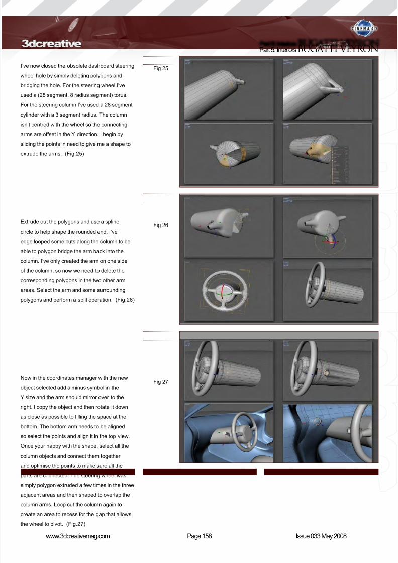
8/10/2019 3DCreative Magazine Issue 033 May 2008
http://slidepdf.com/reader/full/3dcreative-magazine-issue-033-may-2008 127/224
Page 158www.3dcreativemag.com Issue 033 May 2008
Part 5: InteriorsBUGATTI VEYRON
I’ve now closed the obsolete dashboard steering
wheel hole by simply deleting polygons and
bridging the hole. For the steering wheel I’ve
used a (28 segment, 8 radius segment) torus.
For the steering column I’ve used a 28 segment
cylinder with a 3 segment radius. The column
isn’t centred with the wheel so the connecting
arms are offset in the Y direction. I begin by
sliding the points in need to give me a shape to
extrude the arms. (Fig.25)
Extrude out the polygons and use a spline
circle to help shape the rounded end. I’ve
edge looped some cuts along the column to be
able to polygon bridge the arm back into the
column. I’ve only created the arm on one side
of the column, so now we need to delete the
corresponding polygons in the two other arm
areas. Select the arm and some surrounding
polygons and perform a split operation. (Fig.26)
Now in the coordinates manager with the new
object selected add a minus symbol in the
Y size and the arm should mirror over to the
right. I copy the object and then rotate it down
as close as possible to lling the space at the
bottom. The bottom arm needs to be aligned
so select the points and align it in the top view.
Once your happy with the shape, select all the
column objects and connect them together
and optimise the points to make sure all the
parts are connected. The steering wheel was
simply polygon extruded a few times in the three
adjacent areas and then shaped to overlap the
column arms. Loop cut the column again to
create an area to recess for the gap that allows
the wheel to pivot. (Fig.27)
Fig 25
Fig 26
Fig 27

8/10/2019 3DCreative Magazine Issue 033 May 2008
http://slidepdf.com/reader/full/3dcreative-magazine-issue-033-may-2008 128/224

8/10/2019 3DCreative Magazine Issue 033 May 2008
http://slidepdf.com/reader/full/3dcreative-magazine-issue-033-may-2008 129/224
Page 160www.3dcreativemag.com Issue 033 May 2008
Part 5: InteriorsBUGATTI VEYRON
Now we need to add some windows, rst select
the polygons around the windscreen on the
rear body object and split them. Now connect
the edges from top to bottom then loop cut to
add enough points to weld the edges together.
To add thickness simply select all the polygons
and extrude with the caps option selected. To
make sure there are no gaps edge loop select
the outer edges and fully weight them (‘full stop’
and drag right or left) and the windscreen is
complete. (Fig.31)
The rear window is very simple, just add a cube
to the required thickness and position it in the
gap we left earlier. (Fig.32)
The door window will take a little more work
so select the polygons around the window
on the rear body object and split them. Start
creating polygons and bridging in between,
remember to follow all of the curves. Once your
happy perform the same extrude and weighting
techniques as used on the windscreen. (Fig.33)
Fig 31
Fig 32
Fig 33
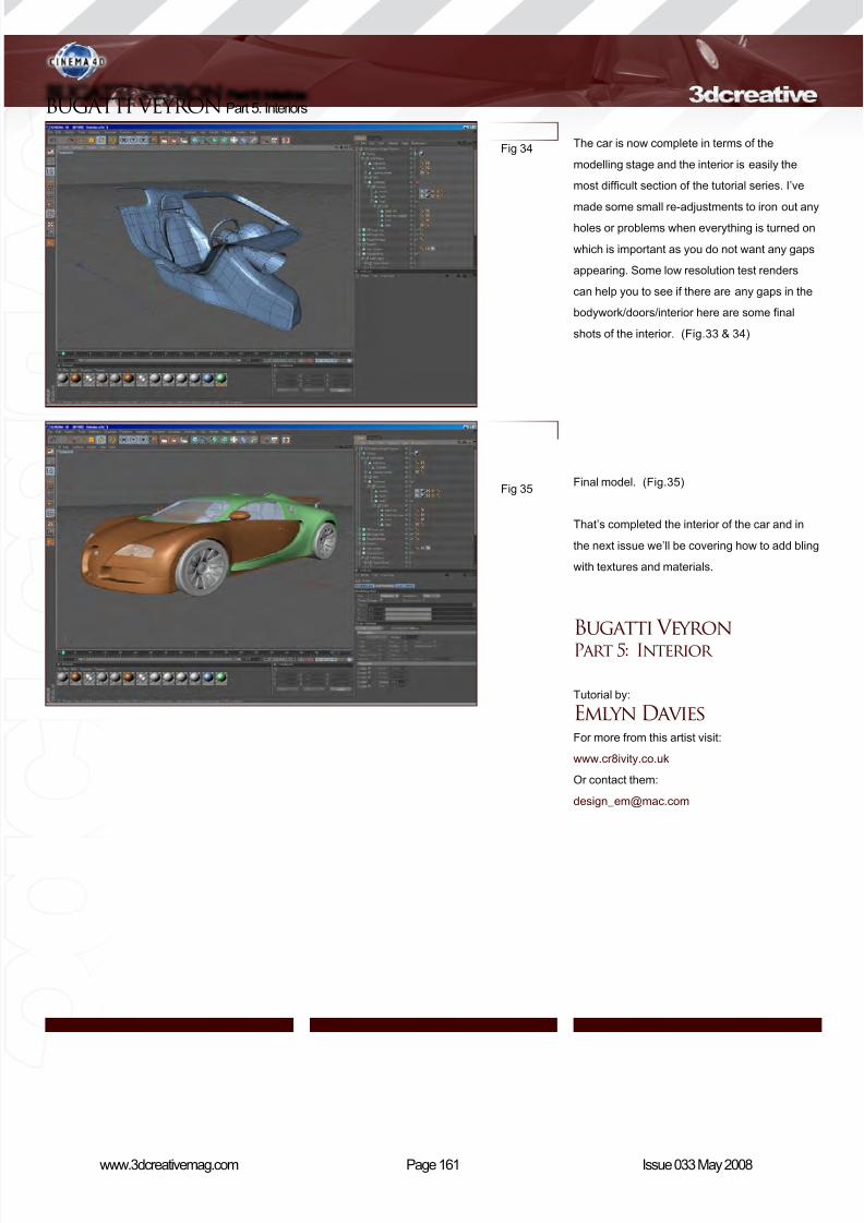
8/10/2019 3DCreative Magazine Issue 033 May 2008
http://slidepdf.com/reader/full/3dcreative-magazine-issue-033-may-2008 130/224
Page 161www.3dcreativemag.com Issue 033 May 2008
BUGATTI VEYRON Part 5: Interiors
The car is now complete in terms of the
modelling stage and the interior is easily the
most difcult section of the tutorial series. I’ve
made some small re-adjustments to iron out any
holes or problems when everything is turned on
which is important as you do not want any gaps
appearing. Some low resolution test renders
can help you to see if there are any gaps in the
bodywork/doors/interior here are some nal
shots of the interior. (Fig.33 & 34)
Final model. (Fig.35)
That’s completed the interior of the car and in
the next issue we’ll be covering how to add bling
with textures and materials.
Bugatti VeyronPart 5: Interior
Tutorial by:
Emlyn DaviesFor more from this artist visit:
www.cr8ivity.co.uk
Or contact them:
Fig 34
Fig 35

8/10/2019 3DCreative Magazine Issue 033 May 2008
http://slidepdf.com/reader/full/3dcreative-magazine-issue-033-may-2008 131/224
The series will cover an in-depth and comprehensive guide to
modelling the amazing Bugatti Veyron car, from start to nish,
and will focus on the key techniques and stages involved in
building the chassis, as well as details such as the windows,
lights, vents, petrol caps, engine parts and so on. We will then
move on to creating the wheels, including tyres and hubcaps,
before going on to building and incorporating an interior, namely
the dashboard and seating. The series will proceed with a
section on creating and applying materials for the numerous
parts of the car, such as the paint work, chrome, rubber and
glass, before concluding with a tutorial devoted to setting
the scene for a nished render. The nal part will cover the
importance of a good lighting rig and light parameters, as well
as the importance of a camera and the integral part that the
rendering settings play in showcasing the model for a portfolio.
This series aims to show a comprehensive guide to creating
a nished car for people new to this type of exercise, but is
not suitable for beginners who are not familiar with using 3D
software. The tutorials do not detail every single step of adding
individual edge loops and vertices, but does endeavour to
outline each important stage and explain the crucial techniques
necessary to following the exercise.
The schedule is as follows:
Issue 029 January 2008
Modelling the Chassis - Basics
Issue 031 March 2008Modelling the Chassis - Details
Issue 031 March 2008
Lights, Radiator Grill & Vents
Issue 032 April 2008
Wheels, Tyres & Rims
Issue 033 May 2008
Interior
Issue 034 June 2008
The Materials & Finishes
Issue 035 July 2008
Lighting Set up & Render
Enjoy ...
Bugatti Veyron car modelling series
www.the-blueprints.com
Blueprints available here:
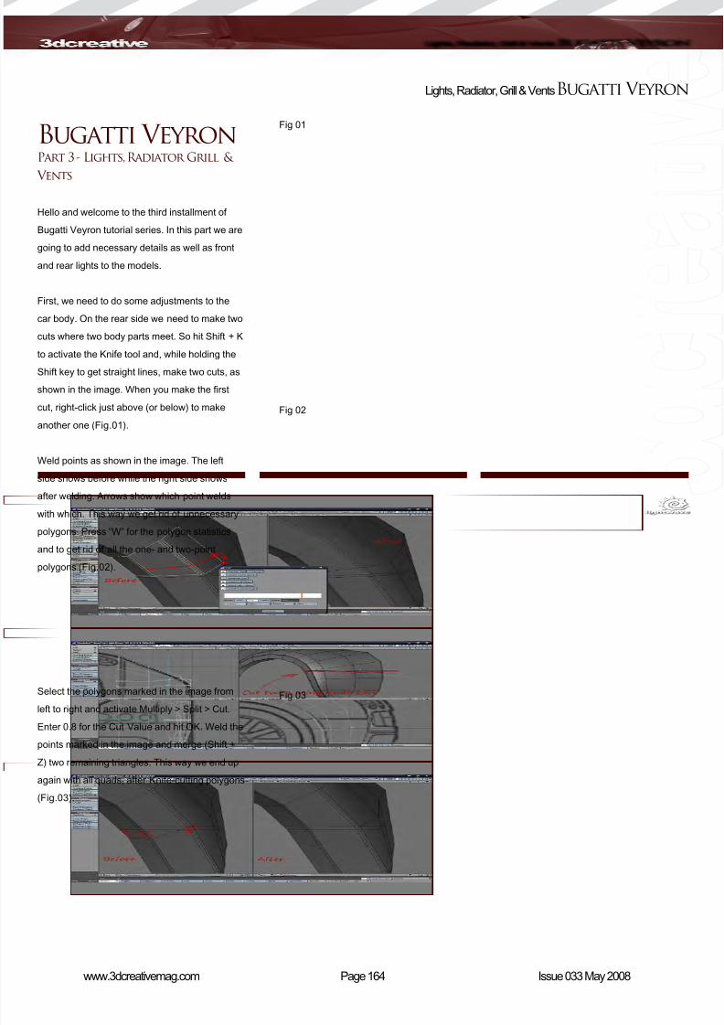
8/10/2019 3DCreative Magazine Issue 033 May 2008
http://slidepdf.com/reader/full/3dcreative-magazine-issue-033-may-2008 132/224
Page 164www.3dcreativemag.com Issue 033 May 2008
Lights, Radiator, Grill & VentsBugatti Veyron
Bugatti Veyron Part 3 - Lights, Radiator Grill &
Vents
Hello and welcome to the third installment of
Bugatti Veyron tutorial series. In this part we are
going to add necessary details as well as front
and rear lights to the models.
First, we need to do some adjustments to the
car body. On the rear side we need to make two
cuts where two body parts meet. So hit Shift + K
to activate the Knife tool and, while holding theShift key to get straight lines, make two cuts, as
shown in the image. When you make the rst
cut, right-click just above (or below) to make
another one (Fig.01).
Weld points as shown in the image. The left
side shows before while the right side shows
after welding. Arrows show which point welds
with which. This way we get rid of unnecessary
polygons. Press “W” for the polygon statistics
and to get rid of all the one- and two-point
polygons (Fig.02).
Select the polygons marked in the image from
left to right and activate Multiply > Split > Cut.
Enter 0.8 for the Cut Value and hit OK. Weld the
points marked in the image and merge (Shift +
Z) two remaining triangles. This way we end up
again with all quads, after Knife-cutting polygons
(Fig.03).
Fig 01
Fig 02
Fig 03

8/10/2019 3DCreative Magazine Issue 033 May 2008
http://slidepdf.com/reader/full/3dcreative-magazine-issue-033-may-2008 133/224
Page 165www.3dcreativemag.com Issue 033 May 2008
Bugatti Veyron Lights, Radiator, Grill & Vents
Select the polygon band where two body parts
meet. Press “E” to extend polygons and scale
polygons down slightly. Hit “E” again and scale
them down again, this time a little more (Fig.04).
Now we need to x the cut that is on the other
side of the wheel gap. Weld the point as it’s
marked in image. Press “W” to pop up the
polygon statistics and delete all the one- and
two-point polygons (Fig.05).
Select edge points and extend and scale them
twice, just like we did in Fig04 with the polygons.
As you can see, the Extender Plus tool (“E”)
works the same with points and polygons
(Fig.06).
Fig 04
Fig 05
Fig 06
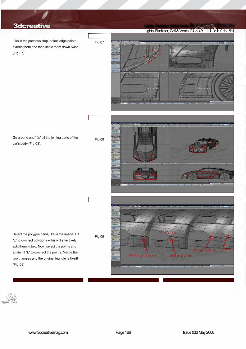
8/10/2019 3DCreative Magazine Issue 033 May 2008
http://slidepdf.com/reader/full/3dcreative-magazine-issue-033-may-2008 134/224
Page 166www.3dcreativemag.com Issue 033 May 2008
Lights, Radiator, Grill & VentsBugatti Veyron
Like in the previous step, select edge points,
extend them and then scale them down twice
(Fig.07).
Go around and “x” all the joining parts of the
car’s body (Fig.08).
Select the polygon band, like in the image. Hit
“L” to connect polygons – this will effectively
split them in two. Now, select the points and
again hit “L” to connect the points. Merge the
two triangles and the original triangle is xed!
(Fig.09)
Fig 07
Fig 08
Fig 09
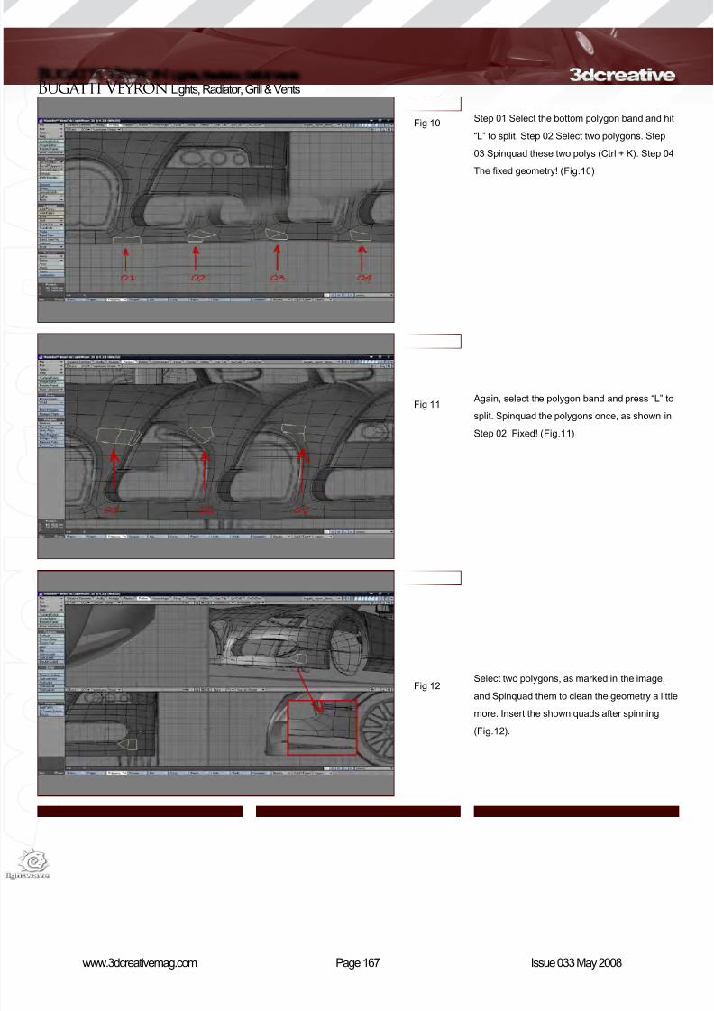
8/10/2019 3DCreative Magazine Issue 033 May 2008
http://slidepdf.com/reader/full/3dcreative-magazine-issue-033-may-2008 135/224
Page 167www.3dcreativemag.com Issue 033 May 2008
Bugatti Veyron Lights, Radiator, Grill & Vents
Step 01 Select the bottom polygon band and hit
“L” to split. Step 02 Select two polygons. Step
03 Spinquad these two polys (Ctrl + K). Step 04
The xed geometry! (Fig.10)
Again, select the polygon band and press “L” to
split. Spinquad the polygons once, as shown in
Step 02. Fixed! (Fig.11)
Select two polygons, as marked in the image,
and Spinquad them to clean the geometry a little
more. Insert the shown quads after spinning
(Fig.12).
Fig 10
Fig 11
Fig 12
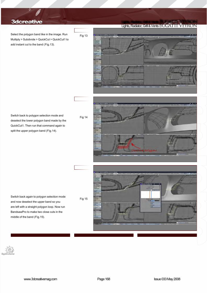
8/10/2019 3DCreative Magazine Issue 033 May 2008
http://slidepdf.com/reader/full/3dcreative-magazine-issue-033-may-2008 136/224
Page 168www.3dcreativemag.com Issue 033 May 2008
Lights, Radiator, Grill & VentsBugatti Veyron
Select the polygon band like in the image. Run
Multiply > Subdivide > QuickCut > QuickCut1 to
add instant cut to the band (Fig.13).
Switch back to polygon selection mode and
deselect the lower polygon band made by the
QuickCut1. Then run that command again to
split the upper polygon band (Fig.14).
Switch back again to polygon selection mode
and now deselect the upper band so you
are left with a straight polygon loop. Now run
BandsawPro to make two close cuts in the
middle of the band (Fig.15).
Fig 13
Fig 14
Fig 15
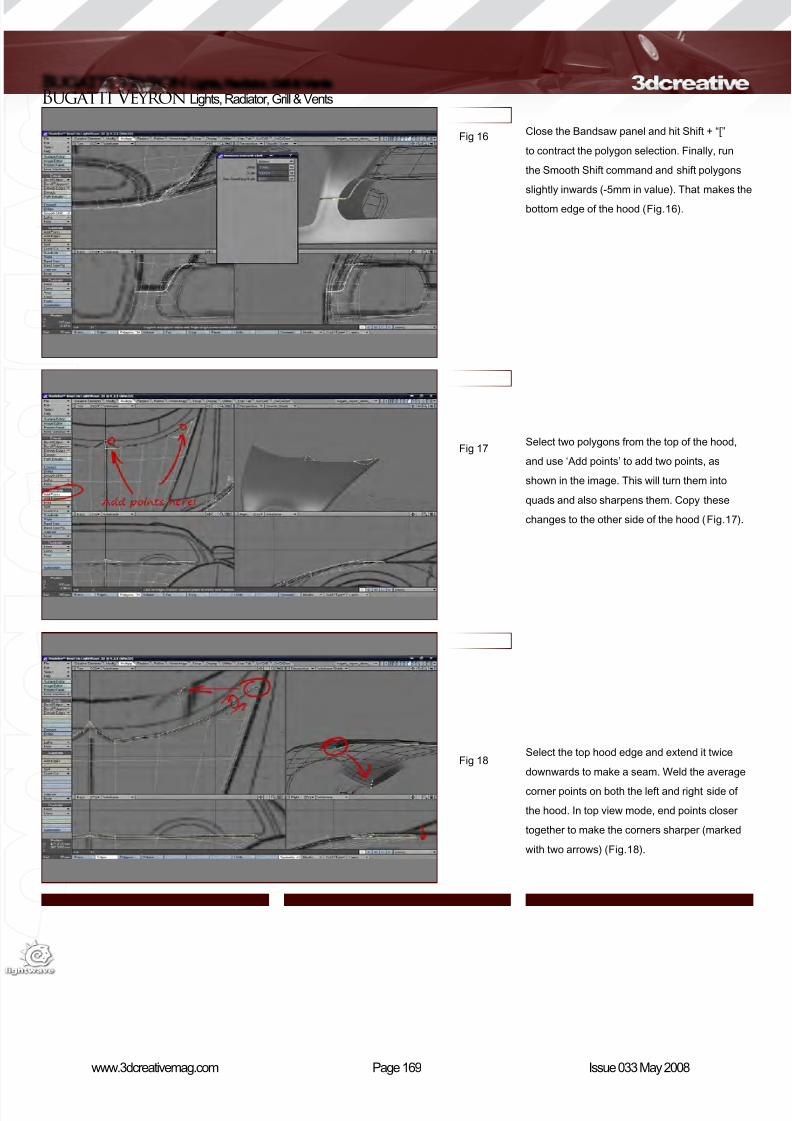
8/10/2019 3DCreative Magazine Issue 033 May 2008
http://slidepdf.com/reader/full/3dcreative-magazine-issue-033-may-2008 137/224
Page 169www.3dcreativemag.com Issue 033 May 2008
Bugatti Veyron Lights, Radiator, Grill & Vents
Close the Bandsaw panel and hit Shift + “[”
to contract the polygon selection. Finally, run
the Smooth Shift command and shift polygons
slightly inwards (-5mm in value). That makes the
bottom edge of the hood (Fig.16).
Select two polygons from the top of the hood,
and use ‘Add points’ to add two points, as
shown in the image. This will turn them into
quads and also sharpens them. Copy these
changes to the other side of the hood (Fig.17).
Select the top hood edge and extend it twice
downwards to make a seam. Weld the average
corner points on both the left and right side of
the hood. In top view mode, end points closer
together to make the corners sharper (marked
with two arrows) (Fig.18).
Fig 16
Fig 17
Fig 18

8/10/2019 3DCreative Magazine Issue 033 May 2008
http://slidepdf.com/reader/full/3dcreative-magazine-issue-033-may-2008 138/224

8/10/2019 3DCreative Magazine Issue 033 May 2008
http://slidepdf.com/reader/full/3dcreative-magazine-issue-033-may-2008 139/224
Page 171www.3dcreativemag.com Issue 033 May 2008
Bugatti Veyron Lights, Radiator, Grill & Vents
Now extend it a few more times and push the
rim deeper inside the car. The central air duct is
fairly deep in the Bugatti Veyron (Fig.22).
Extend the inner edge twice more and stretch
it down on the X-axis. Remove some of the
upper and lower triangles. (This part is quite
insignicant as it will be totally black.) (Fig.23).
Using the same technique create two black-
holed polygons. You can also select points and
hit “P” to make polygons (Fig.24).
Fig 22
Fig 23
Fig 24

8/10/2019 3DCreative Magazine Issue 033 May 2008
http://slidepdf.com/reader/full/3dcreative-magazine-issue-033-may-2008 140/224
Page 172www.3dcreativemag.com Issue 033 May 2008
Lights, Radiator, Grill & VentsBugatti Veyron
Select two edges in the middle of the rim; Edge
bevel them once and select the newly created
polygons. Extend them once and lift them up a
little. Use the Drag point tool (Ctrl + T) to adjust
the shape into more triangular and pointy ones
(Fig.25).
Select the polygons, as in the image. Press
“E” to extend them once and to stretch them
downwards about 25% on the Y-axis (Step 02).
Bandsaw these polygons with one cut on about
50% and hit Space to switch to point selection
mode. This will leave you with points in the
middle selected. Scale these points down to
90% (Step 03). In side view, adjust the point
rows of the seam and bottom so they t the
background image (Fig.26).
Again, select the shown polygons. Extend
them once and move them slightly inwards.
Extend them again and push them more into the
bumper. Select the lower polygons (Step 03)
and move them up a little (Fig.27).
Fig 25
Fig 26
Fig 27
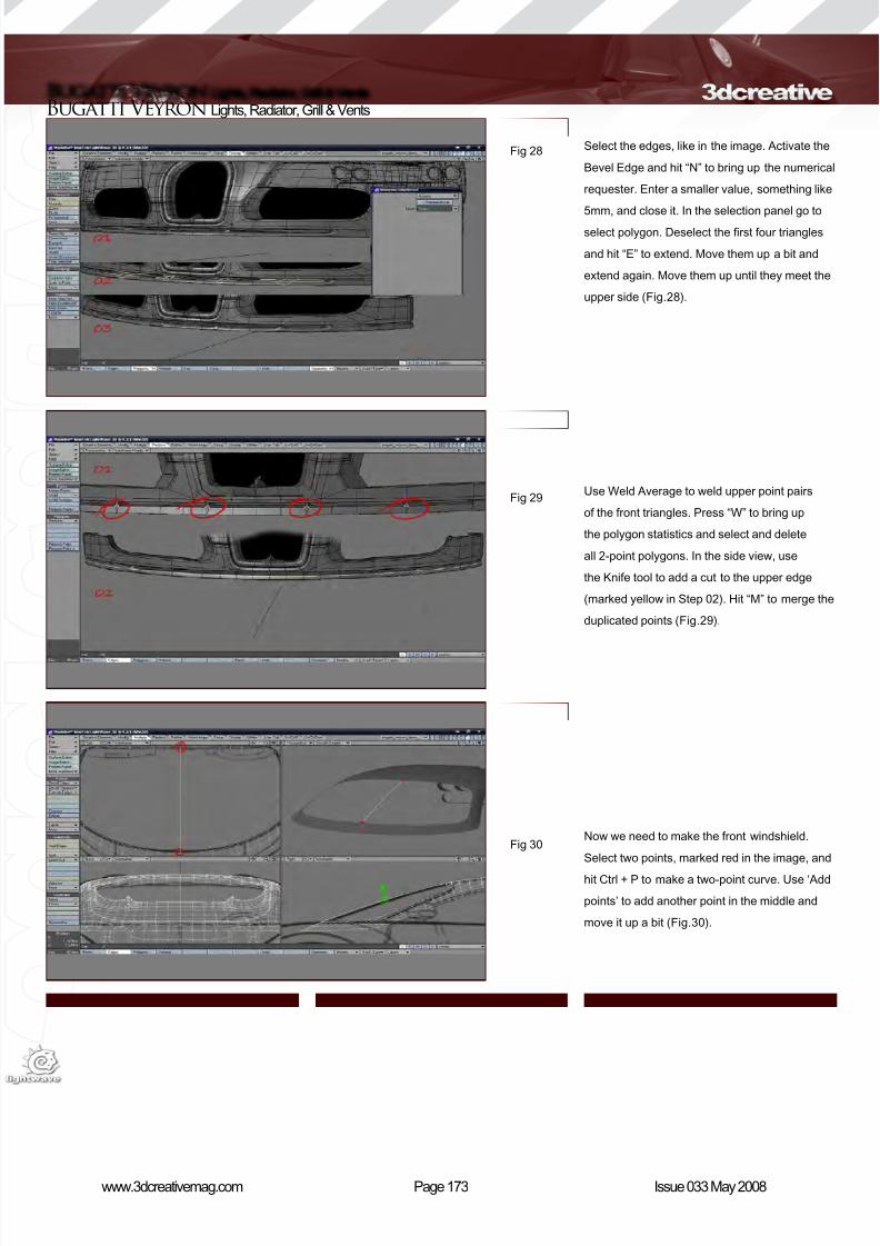
8/10/2019 3DCreative Magazine Issue 033 May 2008
http://slidepdf.com/reader/full/3dcreative-magazine-issue-033-may-2008 141/224
Page 173www.3dcreativemag.com Issue 033 May 2008
Bugatti Veyron Lights, Radiator, Grill & Vents
Select the edges, like in the image. Activate the
Bevel Edge and hit “N” to bring up the numerical
requester. Enter a smaller value, something like
5mm, and close it. In the selection panel go to
select polygon. Deselect the rst four triangles
and hit “E” to extend. Move them up a bit and
extend again. Move them up until they meet the
upper side (Fig.28).
Use Weld Average to weld upper point pairs
of the front triangles. Press “W” to bring up
the polygon statistics and select and delete
all 2-point polygons. In the side view, use
the Knife tool to add a cut to the upper edge
(marked yellow in Step 02). Hit “M” to merge the
duplicated points (Fig.29).
Now we need to make the front windshield.
Select two points, marked red in the image, and
hit Ctrl + P to make a two-point curve. Use ‘Add
points’ to add another point in the middle and
move it up a bit (Fig.30).
Fig 28
Fig 29
Fig 30
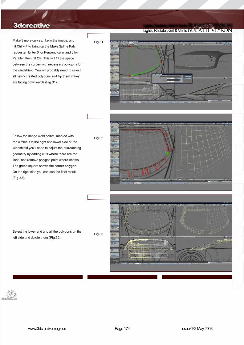
8/10/2019 3DCreative Magazine Issue 033 May 2008
http://slidepdf.com/reader/full/3dcreative-magazine-issue-033-may-2008 142/224
Page 174www.3dcreativemag.com Issue 033 May 2008
Lights, Radiator, Grill & VentsBugatti Veyron
Make 3 more curves, like in the image, and
hit Ctrl + F to bring up the Make Spline Patch
requester. Enter 6 for Perpendicular and 8 for
Parallel, then hit OK. This will ll the space
between the curves with necessary polygons for
the windshield. You will probably need to select
all newly created polygons and ip them if they
are facing downwards (Fig.31).
Follow the image weld points, marked with
red circles. On the right and lower side of the
windshield you’ll need to adjust the surrounding
geometry by adding cuts where there are red
lines, and remove polygon pairs where shown.
The green square shows the corner polygon.
On the right side you can see the nal result
(Fig.32).
Select the lower end and all the polygons on the
left side and delete them (Fig.32).
Fig 31
Fig 32
Fig 33
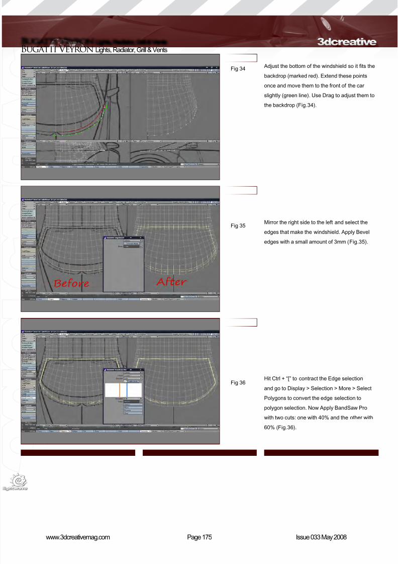
8/10/2019 3DCreative Magazine Issue 033 May 2008
http://slidepdf.com/reader/full/3dcreative-magazine-issue-033-may-2008 143/224
Page 175www.3dcreativemag.com Issue 033 May 2008
Bugatti Veyron Lights, Radiator, Grill & Vents
Adjust the bottom of the windshield so it ts the
backdrop (marked red). Extend these points
once and move them to the front of the car
slightly (green line). Use Drag to adjust them to
the backdrop (Fig.34).
Mirror the right side to the left and select the
edges that make the windshield. Apply Bevel
edges with a small amount of 3mm (Fig.35).
Hit Ctrl + “[” to contract the Edge selection
and go to Display > Selection > More > Select
Polygons to convert the edge selection to
polygon selection. Now Apply BandSaw Pro
with two cuts: one with 40% and the other with
60% (Fig.36).
Fig 34
Fig 35
Fig 36

8/10/2019 3DCreative Magazine Issue 033 May 2008
http://slidepdf.com/reader/full/3dcreative-magazine-issue-033-may-2008 144/224
Page 176www.3dcreativemag.com Issue 033 May 2008
Lights, Radiator, Grill & VentsBugatti Veyron
Hit Ctrl + “[” again to contract the polygon
selection. Move the selected polygons down
about 1mm, hit “E” to extend them once, and
move them downwards again for some 4-5mm.
Now we have the edge between the windshield
and car’s body (Fig.37).
Move the corner points of the upper side to
make the windshield rounder, and select two
polygons, like in the image, and apply Bandglue
to join the polygons and make the body edge
softer (Fig.38).
Use the corner points of the surrounding car
parts to make four curves for the side window.
Subpatch curves to make a 5x5 polygon window
(Fig.39).
Fig 37
Fig 38
Fig 39
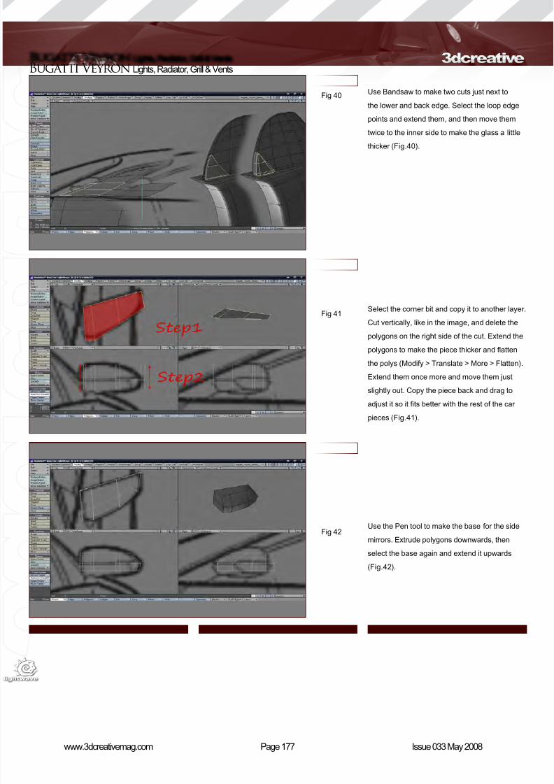
8/10/2019 3DCreative Magazine Issue 033 May 2008
http://slidepdf.com/reader/full/3dcreative-magazine-issue-033-may-2008 145/224
Page 177www.3dcreativemag.com Issue 033 May 2008
Bugatti Veyron Lights, Radiator, Grill & Vents
Use Bandsaw to make two cuts just next to
the lower and back edge. Select the loop edge
points and extend them, and then move them
twice to the inner side to make the glass a little
thicker (Fig.40).
Select the corner bit and copy it to another layer.
Cut vertically, like in the image, and delete the
polygons on the right side of the cut. Extend the
polygons to make the piece thicker and atten
the polys (Modify > Translate > More > Flatten).
Extend them once more and move them just
slightly out. Copy the piece back and drag to
adjust it so it ts better with the rest of the car
pieces (Fig.41).
Use the Pen tool to make the base for the side
mirrors. Extrude polygons downwards, then
select the base again and extend it upwards
(Fig.42).
Fig 40
Fig 41
Fig 42
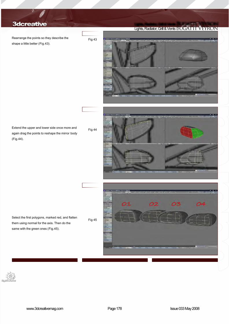
8/10/2019 3DCreative Magazine Issue 033 May 2008
http://slidepdf.com/reader/full/3dcreative-magazine-issue-033-may-2008 146/224
Page 178www.3dcreativemag.com Issue 033 May 2008
Lights, Radiator, Grill & VentsBugatti Veyron
Rearrange the points so they describe the
shape a little better (Fig.43).
Extend the upper and lower side once more and
again drag the points to reshape the mirror body
(Fig.44).
Select the rst polygons, marked red, and atten
them using normal for the axis. Then do the
same with the green ones (Fig.45).
Fig 43
Fig 44
Fig 45
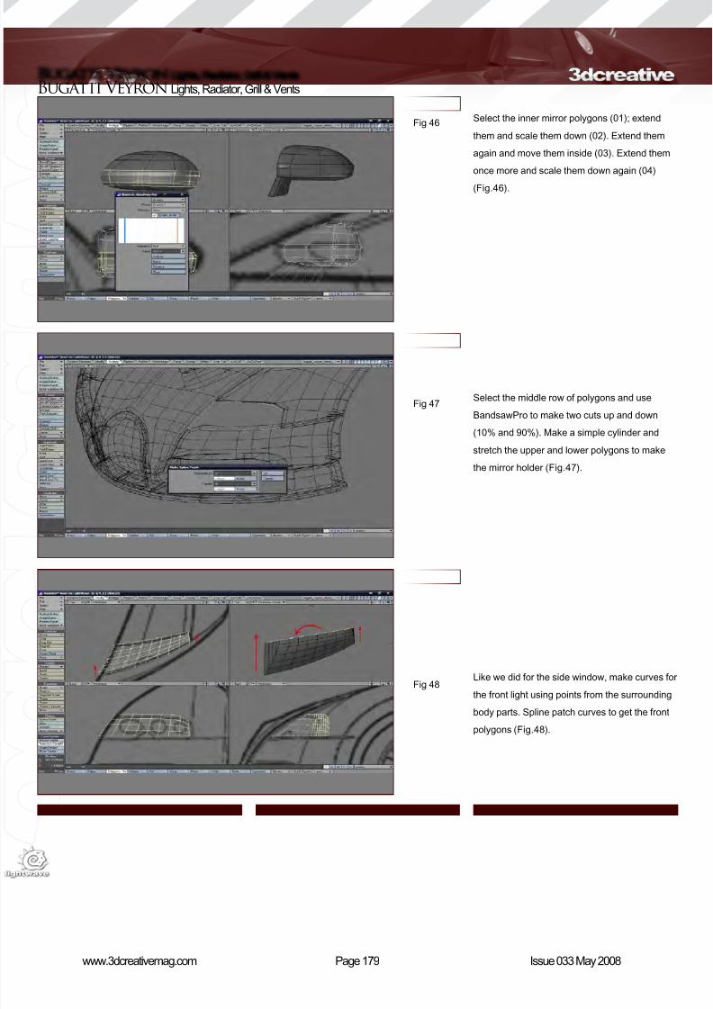
8/10/2019 3DCreative Magazine Issue 033 May 2008
http://slidepdf.com/reader/full/3dcreative-magazine-issue-033-may-2008 147/224
Page 179www.3dcreativemag.com Issue 033 May 2008
Bugatti Veyron Lights, Radiator, Grill & Vents
Select the inner mirror polygons (01); extend
them and scale them down (02). Extend them
again and move them inside (03). Extend them
once more and scale them down again (04)
(Fig.46).
Select the middle row of polygons and use
BandsawPro to make two cuts up and down
(10% and 90%). Make a simple cylinder and
stretch the upper and lower polygons to make
the mirror holder (Fig.47).
Like we did for the side window, make curves for
the front light using points from the surrounding
body parts. Spline patch curves to get the front
polygons (Fig.48).
Fig 46
Fig 47
Fig 48
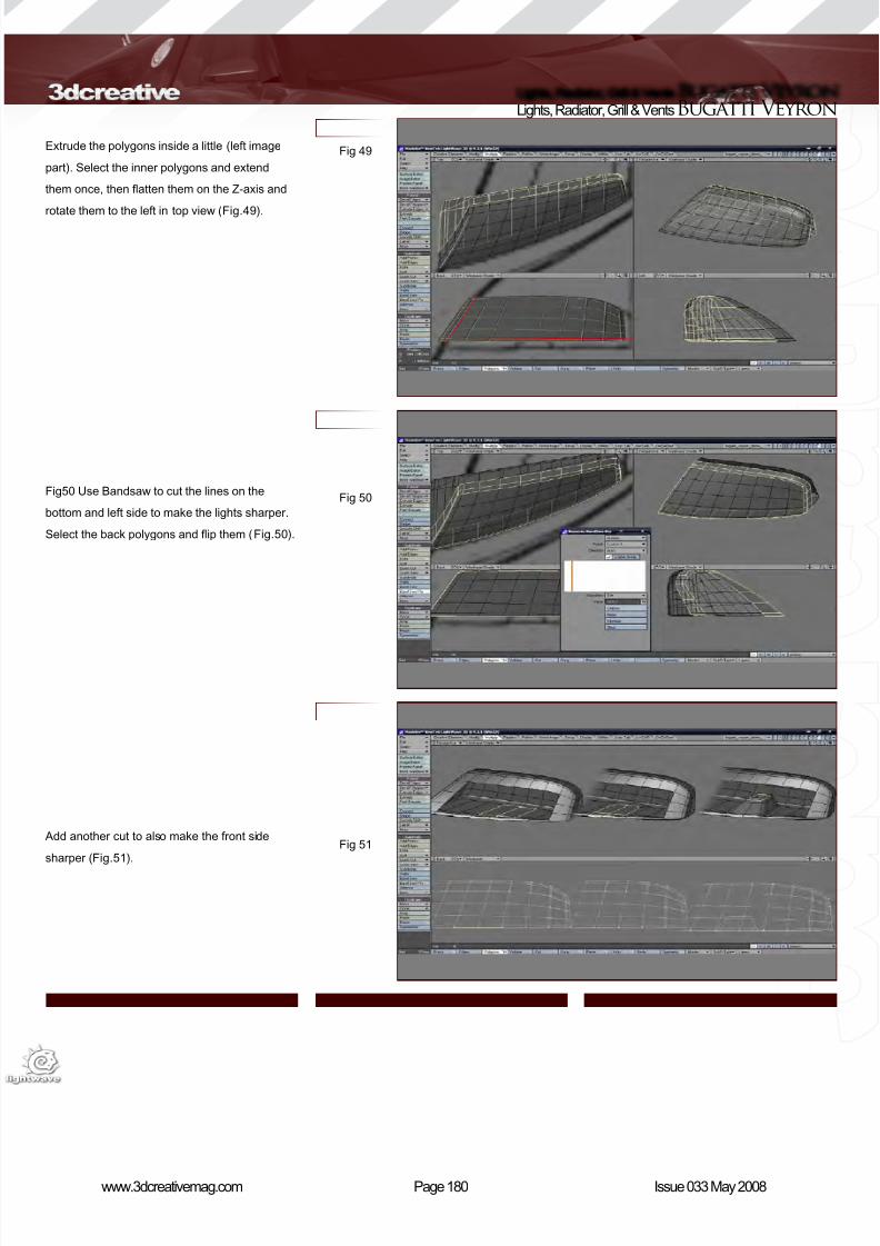
8/10/2019 3DCreative Magazine Issue 033 May 2008
http://slidepdf.com/reader/full/3dcreative-magazine-issue-033-may-2008 148/224
Page 180www.3dcreativemag.com Issue 033 May 2008
Lights, Radiator, Grill & VentsBugatti Veyron
Extrude the polygons inside a little (left image
part). Select the inner polygons and extend
them once, then atten them on the Z-axis and
rotate them to the left in top view (Fig.49).
Fig50 Use Bandsaw to cut the lines on the
bottom and left side to make the lights sharper.
Select the back polygons and ip them (Fig.50).
Add another cut to also make the front side
sharper (Fig.51).
Fig 49
Fig 50
Fig 51
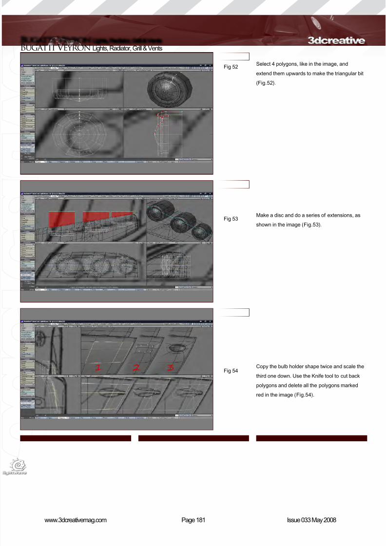
8/10/2019 3DCreative Magazine Issue 033 May 2008
http://slidepdf.com/reader/full/3dcreative-magazine-issue-033-may-2008 149/224
Page 181www.3dcreativemag.com Issue 033 May 2008
Bugatti Veyron Lights, Radiator, Grill & Vents
Fig 52
Fig 53
Fig 54
Select 4 polygons, like in the image, and
extend them upwards to make the triangular bit
(Fig.52).
Make a disc and do a series of extensions, as
shown in the image (Fig.53).
Copy the bulb holder shape twice and scale the
third one down. Use the Knife tool to cut back
polygons and delete all the polygons marked
red in the image (Fig.54).
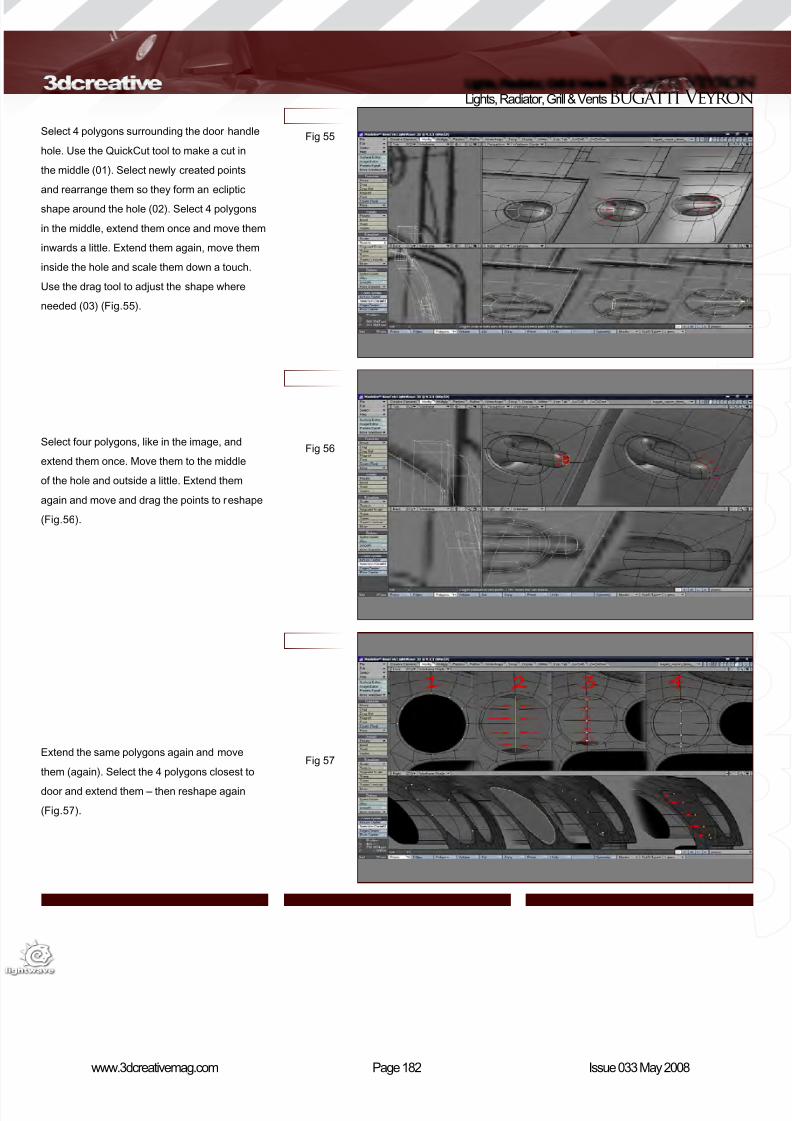
8/10/2019 3DCreative Magazine Issue 033 May 2008
http://slidepdf.com/reader/full/3dcreative-magazine-issue-033-may-2008 150/224
Page 182www.3dcreativemag.com Issue 033 May 2008
Lights, Radiator, Grill & VentsBugatti Veyron
Fig 55
Fig 56
Fig 57
Select 4 polygons surrounding the door handle
hole. Use the QuickCut tool to make a cut in
the middle (01). Select newly created points
and rearrange them so they form an ecliptic
shape around the hole (02). Select 4 polygons
in the middle, extend them once and move them
inwards a little. Extend them again, move them
inside the hole and scale them down a touch.
Use the drag tool to adjust the shape where
needed (03) (Fig.55).
Select four polygons, like in the image, and
extend them once. Move them to the middle
of the hole and outside a little. Extend them
again and move and drag the points to reshape
(Fig.56).
Extend the same polygons again and move
them (again). Select the 4 polygons closest to
door and extend them – then reshape again
(Fig.57).
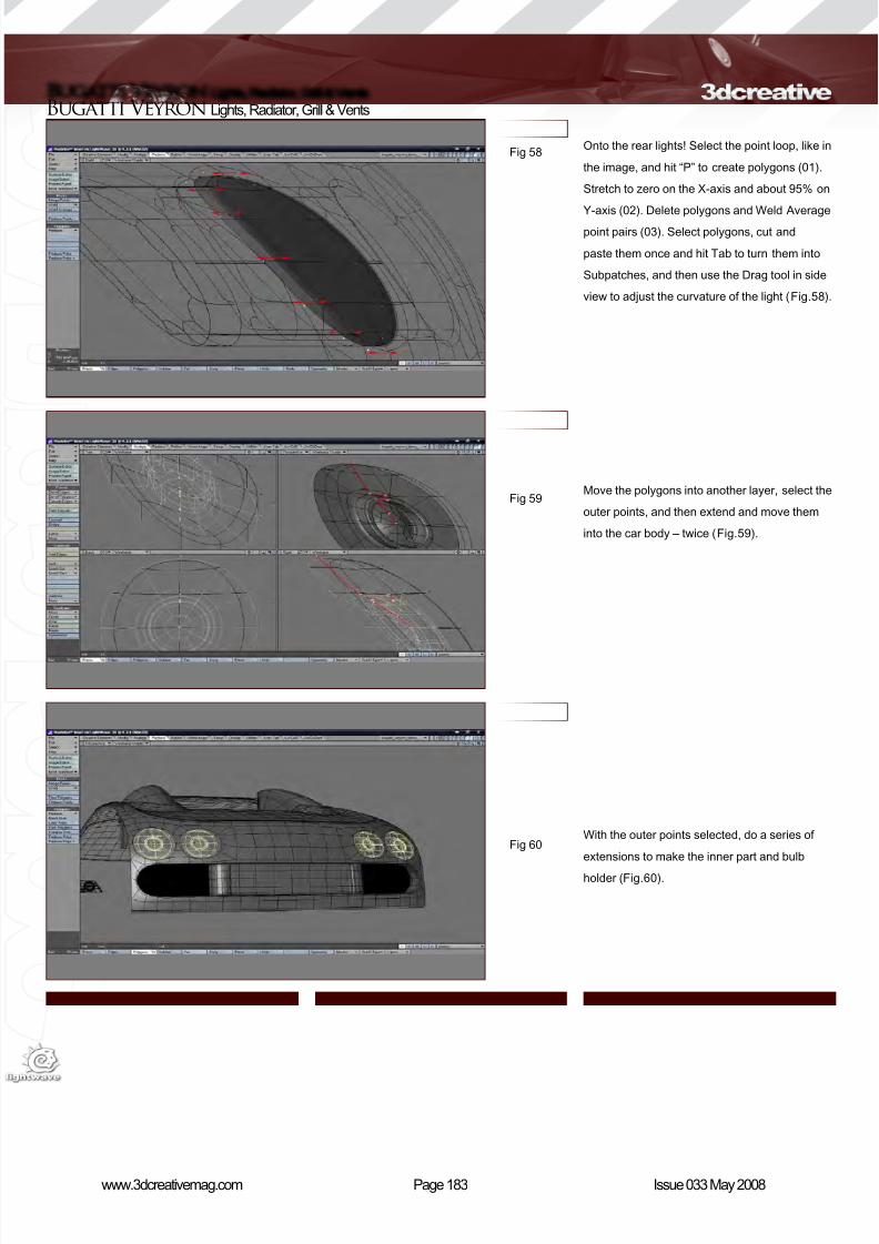
8/10/2019 3DCreative Magazine Issue 033 May 2008
http://slidepdf.com/reader/full/3dcreative-magazine-issue-033-may-2008 151/224
Page 183www.3dcreativemag.com Issue 033 May 2008
Bugatti Veyron Lights, Radiator, Grill & Vents
Fig 58
Fig 59
Fig 60
Onto the rear lights! Select the point loop, like in
the image, and hit “P” to create polygons (01).
Stretch to zero on the X-axis and about 95% on
Y-axis (02). Delete polygons and Weld Average
point pairs (03). Select polygons, cut and
paste them once and hit Tab to turn them into
Subpatches, and then use the Drag tool in side
view to adjust the curvature of the light (Fig.58).
Move the polygons into another layer, select the
outer points, and then extend and move them
into the car body – twice (Fig.59).
With the outer points selected, do a series of
extensions to make the inner part and bulb
holder (Fig.60).
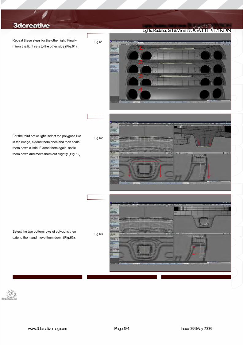
8/10/2019 3DCreative Magazine Issue 033 May 2008
http://slidepdf.com/reader/full/3dcreative-magazine-issue-033-may-2008 152/224
Page 184www.3dcreativemag.com Issue 033 May 2008
Lights, Radiator, Grill & VentsBugatti Veyron
Fig 61
Fig 62
Fig 63
Repeat these steps for the other light. Finally,
mirror the light sets to the other side (Fig.61).
For the third brake light, select the polygons like
in the image, extend them once and then scale
them down a little. Extend them again, scale
them down and move them out slightly (Fig.62).
Select the two bottom rows of polygons then
extend them and move them down (Fig.63).
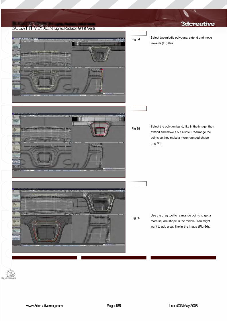
8/10/2019 3DCreative Magazine Issue 033 May 2008
http://slidepdf.com/reader/full/3dcreative-magazine-issue-033-may-2008 153/224
Page 185www.3dcreativemag.com Issue 033 May 2008
Bugatti Veyron Lights, Radiator, Grill & Vents
Fig 64
Fig 65
Fig 66
Select two middle polygons: extend and move
inwards (Fig.64).
Select the polygon band, like in the image, then
extend and move it out a little. Rearrange the
points so they make a more rounded shape
(Fig.65).
Use the drag tool to rearrange points to get a
more square shape in the middle. You might
want to add a cut, like in the image (Fig.66).

8/10/2019 3DCreative Magazine Issue 033 May 2008
http://slidepdf.com/reader/full/3dcreative-magazine-issue-033-may-2008 154/224
Page 186www.3dcreativemag.com Issue 033 May 2008
Lights, Radiator, Grill & VentsBugatti Veyron
Fig 67
Fig 68
Fig 69
Select polygons marked in the image, then
extend them and move them out (Fig.67).
Delete the marked polygons and weld the points
to remove the gaps (Fig.68).
Select the marked polygons then extend and
move them out again – twice! (Fig.69).
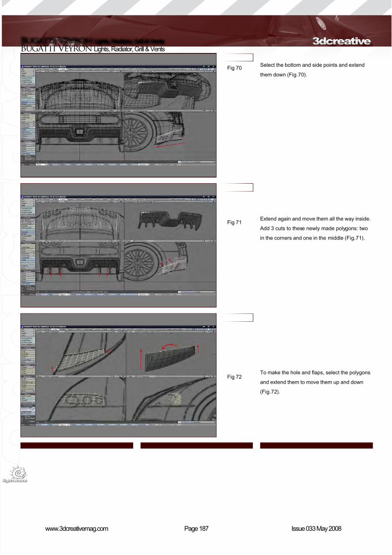
8/10/2019 3DCreative Magazine Issue 033 May 2008
http://slidepdf.com/reader/full/3dcreative-magazine-issue-033-may-2008 155/224
Page 187www.3dcreativemag.com Issue 033 May 2008
Bugatti Veyron Lights, Radiator, Grill & Vents
Fig 70
Fig 71
Fig 72
Select the bottom and side points and extend
them down (Fig.70).
Extend again and move them all the way inside.
Add 3 cuts to these newly made polygons: two
in the corners and one in the middle (Fig.71).
To make the hole and aps, select the polygons
and extend them to move them up and down
(Fig.72).
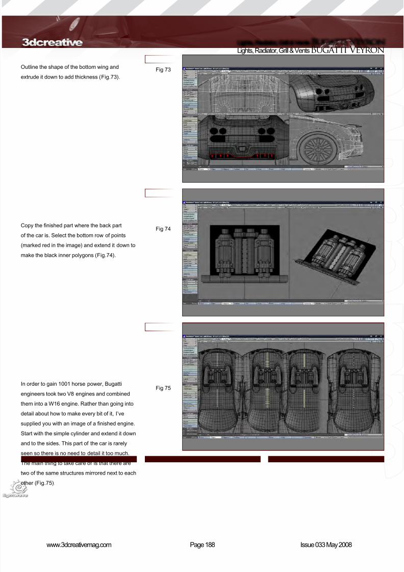
8/10/2019 3DCreative Magazine Issue 033 May 2008
http://slidepdf.com/reader/full/3dcreative-magazine-issue-033-may-2008 156/224
Page 188www.3dcreativemag.com Issue 033 May 2008
Lights, Radiator, Grill & VentsBugatti Veyron
Fig 73
Fig 74
Fig 75
Outline the shape of the bottom wing and
extrude it down to add thickness (Fig.73).
Copy the nished part where the back part
of the car is. Select the bottom row of points
(marked red in the image) and extend it down to
make the black inner polygons (Fig.74).
In order to gain 1001 horse power, Bugatti
engineers took two V8 engines and combined
them into a W16 engine. Rather than going into
detail about how to make every bit of it, I’ve
supplied you with an image of a nished engine.
Start with the simple cylinder and extend it down
and to the sides. This part of the car is rarely
seen so there is no need to detail it too much.
The main thing to take care of is that there are
two of the same structures mirrored next to each
other (Fig.75).
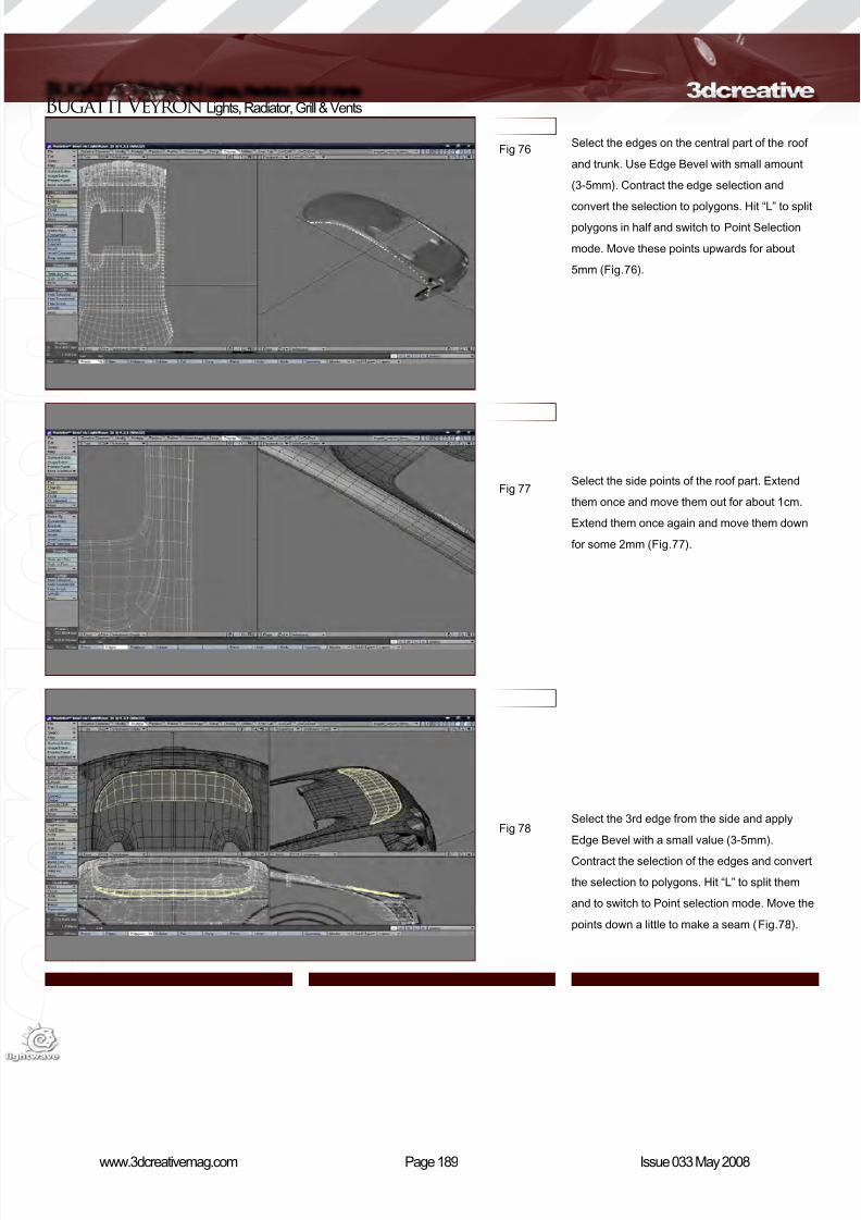
8/10/2019 3DCreative Magazine Issue 033 May 2008
http://slidepdf.com/reader/full/3dcreative-magazine-issue-033-may-2008 157/224
Page 189www.3dcreativemag.com Issue 033 May 2008
Bugatti Veyron Lights, Radiator, Grill & Vents
Fig 76
Fig 77
Fig 78
Select the edges on the central part of the roof
and trunk. Use Edge Bevel with small amount
(3-5mm). Contract the edge selection and
convert the selection to polygons. Hit “L” to split
polygons in half and switch to Point Selection
mode. Move these points upwards for about
5mm (Fig.76).
Select the side points of the roof part. Extend
them once and move them out for about 1cm.
Extend them once again and move them down
for some 2mm (Fig.77).
Select the 3rd edge from the side and apply
Edge Bevel with a small value (3-5mm).
Contract the selection of the edges and convert
the selection to polygons. Hit “L” to split them
and to switch to Point selection mode. Move the
points down a little to make a seam (Fig.78).
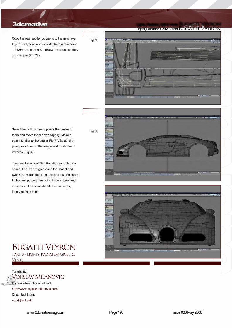
8/10/2019 3DCreative Magazine Issue 033 May 2008
http://slidepdf.com/reader/full/3dcreative-magazine-issue-033-may-2008 158/224
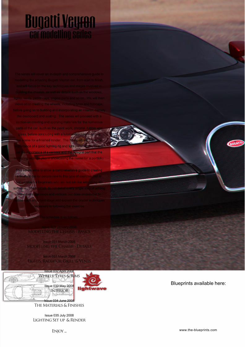
8/10/2019 3DCreative Magazine Issue 033 May 2008
http://slidepdf.com/reader/full/3dcreative-magazine-issue-033-may-2008 159/224
The series will cover an in-depth and comprehensive guide to
modelling the amazing Bugatti Veyron car, from start to nish,
and will focus on the key techniques and stages involved in
building the chassis, as well as details such as the windows,
lights, vents, petrol caps, engine parts and so on. We will then
move on to creating the wheels, including tyres and hubcaps,
before going on to building and incorporating an interior, namely
the dashboard and seating. The series will proceed with a
section on creating and applying materials for the numerous
parts of the car, such as the paint work, chrome, rubber and
glass, before concluding with a tutorial devoted to setting
the scene for a nished render. The nal part will cover the
importance of a good lighting rig and light parameters, as well
as the importance of a camera and the integral part that the
rendering settings play in showcasing the model for a portfolio.
This series aims to show a comprehensive guide to creating
a nished car for people new to this type of exercise, but is
not suitable for beginners who are not familiar with using 3D
software. The tutorials do not detail every single step of adding
individual edge loops and vertices, but does endeavour to
outline each important stage and explain the crucial techniques
necessary to following the exercise.
The schedule is as follows:
Issue 029 January 2008
Modelling the Chassis - Basics
Issue 031 March 2008Modelling the Chassis - Details
Issue 031 March 2008
Lights, Radiator Grill & Vents
Issue 032 April 2008
Wheels, Tyres & Rims
Issue 033 May 2008
Interior
Issue 034 June 2008
The Materials & Finishes
Issue 035 July 2008
Lighting Set up & Render
Enjoy ...
Bugatti Veyron car modelling series
www.the-blueprints.com
Blueprints available here:
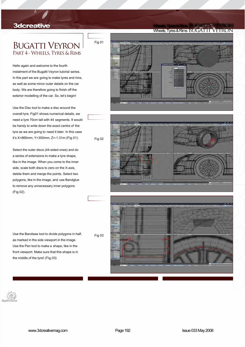
8/10/2019 3DCreative Magazine Issue 033 May 2008
http://slidepdf.com/reader/full/3dcreative-magazine-issue-033-may-2008 160/224
Page 192www.3dcreativemag.com Issue 033 May 2008
Wheels, Tyres & Rims Bugatti Veyron
Bugatti Veyron Part 4 - Wheels, Tyres & Rims
Hello again and welcome to the fourth
instalment of the Bugatti Veyron tutorial series.
In this part we are going to make tyres and rims,
as well as some minor outer details on the car
body. We are therefore going to nish off the
exterior modelling of the car. So, let’s begin!
Use the Disc tool to make a disc around the
overall tyre. Fig01 shows numerical details, we
need a tyre 70cm tall with 44 segments. It would
be handy to write down the exact centre of the
tyre as we are going to need it later. In this case
it’s X=865mm, Y=350mm, Z=-1.31m (Fig.01).
Select the outer discs (44-sided ones) and do
a series of extensions to make a tyre shape,
like in the image. When you come to the inner
side, scale both discs to zero on the X-axis,
delete them and merge the points. Select two
polygons, like in the image, and use Bandglue
to remove any unnecessary inner polygons
(Fig.02).
Use the Bandsaw tool to divide polygons in half,
as marked in the side viewport in the image.
Use the Pen tool to make a shape, like in the
front viewport. Make sure that this shape is in
the middle of the tyre! (Fig.03)
Fig 01
Fig 02
Fig 03
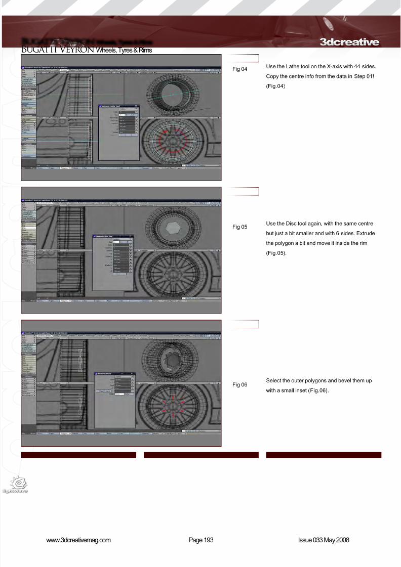
8/10/2019 3DCreative Magazine Issue 033 May 2008
http://slidepdf.com/reader/full/3dcreative-magazine-issue-033-may-2008 161/224
Page 193www.3dcreativemag.com Issue 033 May 2008
Bugatti Veyron Wheels, Tyres & Rims
Use the Lathe tool on the X-axis with 44 sides.
Copy the centre info from the data in Step 01!
(Fig.04)
Use the Disc tool again, with the same centre
but just a bit smaller and with 6 sides. Extrude
the polygon a bit and move it inside the rim
(Fig.05).
Select the outer polygons and bevel them up
with a small inset (Fig.06).
Fig 04
Fig 05
Fig 06

8/10/2019 3DCreative Magazine Issue 033 May 2008
http://slidepdf.com/reader/full/3dcreative-magazine-issue-033-may-2008 162/224
Page 194www.3dcreativemag.com Issue 033 May 2008
Wheels, Tyres & Rims Bugatti Veyron
Bevelling such small polygons makes the end
points go through, so we need to x this by
moving points to the right until the polygons look
correct again (Fig.07).
Select the rim and tyre polygons and rotate
them in the side viewport for 4.06 degrees. To
do this, you’ll need to pick to rotation tool – “Y” –
and rotate just a little in the side viewport (make
sure that Action Center is set to Selection Shift
+ F8). Undo the action and hit “N” for numerical.
This will set the centre and axis right. Enter
360/88 for the value. And that’s how we achieve
4.06 degrees! (Fig.08)
Select two polygons, like in the image, and
activate the Bridge tool to connect them
(Fig.09).
Fig 07
Fig 08
Fig 09
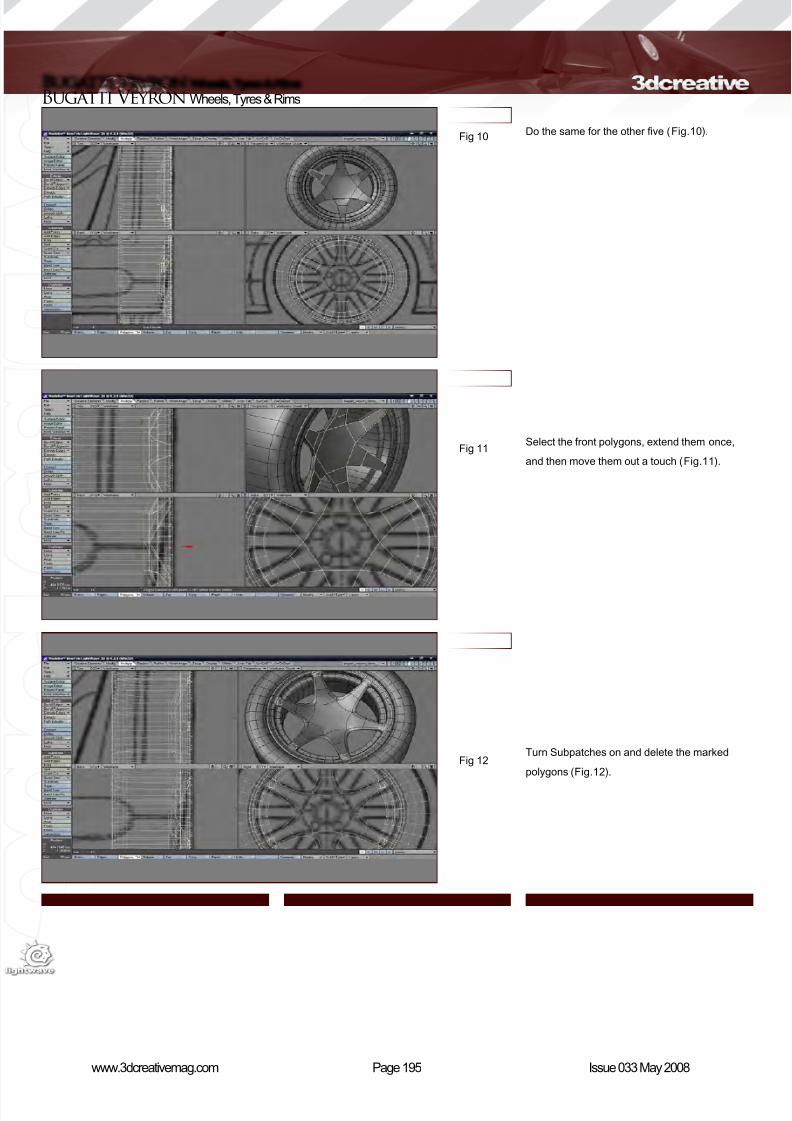
8/10/2019 3DCreative Magazine Issue 033 May 2008
http://slidepdf.com/reader/full/3dcreative-magazine-issue-033-may-2008 163/224

8/10/2019 3DCreative Magazine Issue 033 May 2008
http://slidepdf.com/reader/full/3dcreative-magazine-issue-033-may-2008 164/224
Page 196www.3dcreativemag.com Issue 033 May 2008
Wheels, Tyres & Rims Bugatti Veyron
Weld the two-point pairs to remove the gap. Do
the same on the other ve sides (Fig.13).
Select the shown points and move them out
a little to create a more curvaceous shape
(Fig.14).
Make another 6-sided disc and rotate it for 30
degrees. Extrude it again to make it thicker and
bevel it, like in Fig.06. Place it just behind the
one we made earlier (Fig.15).
Fig 13
Fig 14
Fig 15
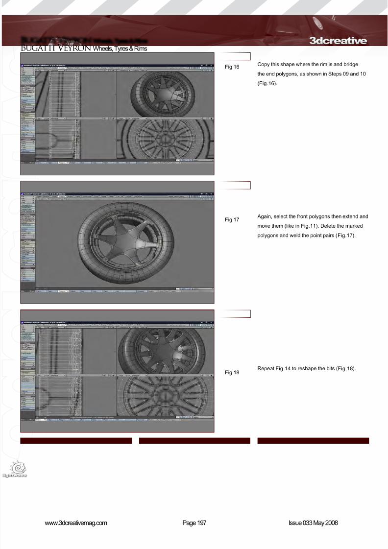
8/10/2019 3DCreative Magazine Issue 033 May 2008
http://slidepdf.com/reader/full/3dcreative-magazine-issue-033-may-2008 165/224
Page 197www.3dcreativemag.com Issue 033 May 2008
Bugatti Veyron Wheels, Tyres & Rims
Copy this shape where the rim is and bridge
the end polygons, as shown in Steps 09 and 10
(Fig.16).
Again, select the front polygons then extend and
move them (like in Fig.11). Delete the marked
polygons and weld the point pairs (Fig.17).
Repeat Fig.14 to reshape the bits (Fig.18).
Fig 16
Fig 17
Fig 18
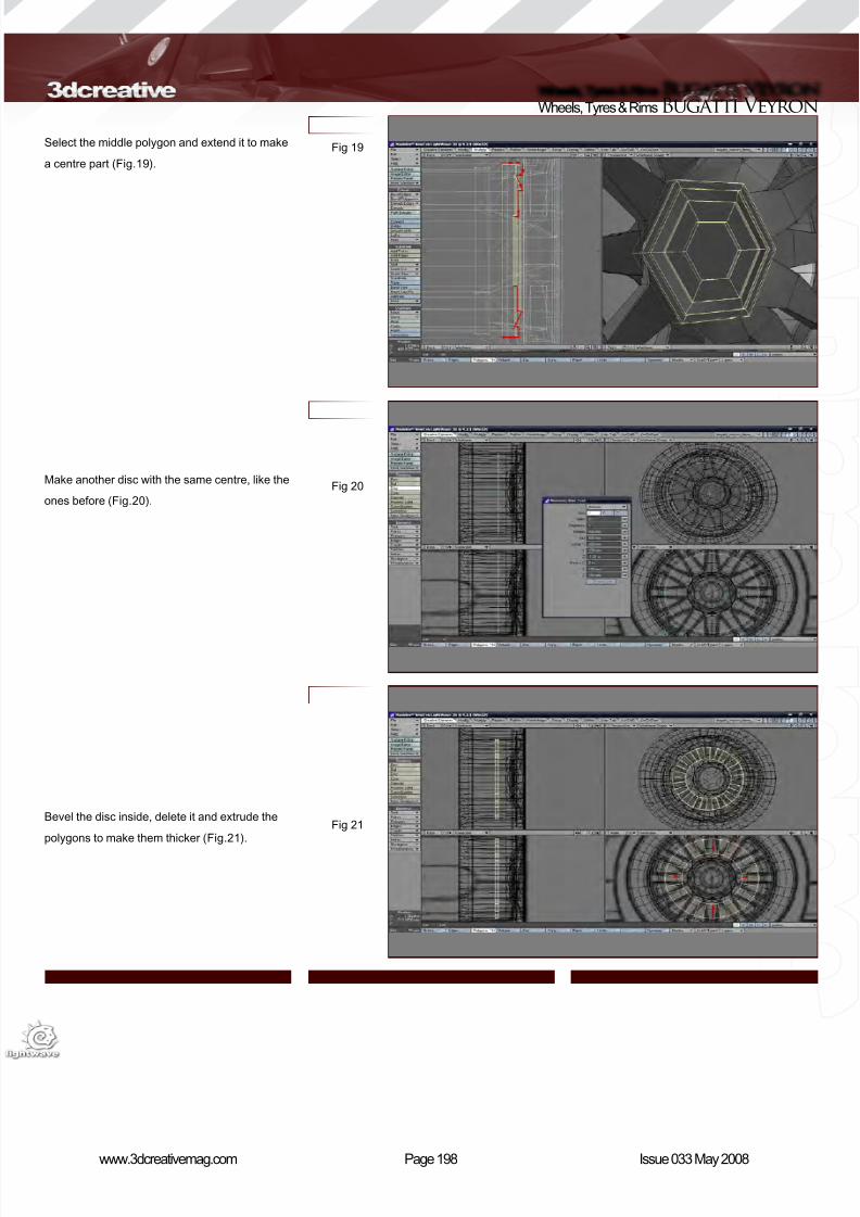
8/10/2019 3DCreative Magazine Issue 033 May 2008
http://slidepdf.com/reader/full/3dcreative-magazine-issue-033-may-2008 166/224
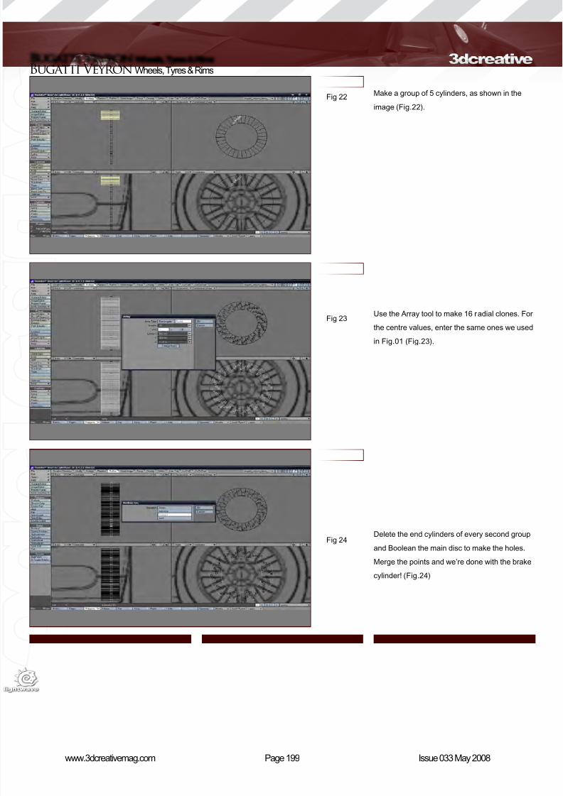
8/10/2019 3DCreative Magazine Issue 033 May 2008
http://slidepdf.com/reader/full/3dcreative-magazine-issue-033-may-2008 167/224
Page 199www.3dcreativemag.com Issue 033 May 2008
Bugatti Veyron Wheels, Tyres & Rims
Make a group of 5 cylinders, as shown in the
image (Fig.22).
Use the Array tool to make 16 radial clones. For
the centre values, enter the same ones we used
in Fig.01 (Fig.23).
Delete the end cylinders of every second group
and Boolean the main disc to make the holes.
Merge the points and we’re done with the brake
cylinder! (Fig.24)
Fig 22
Fig 23
Fig 24
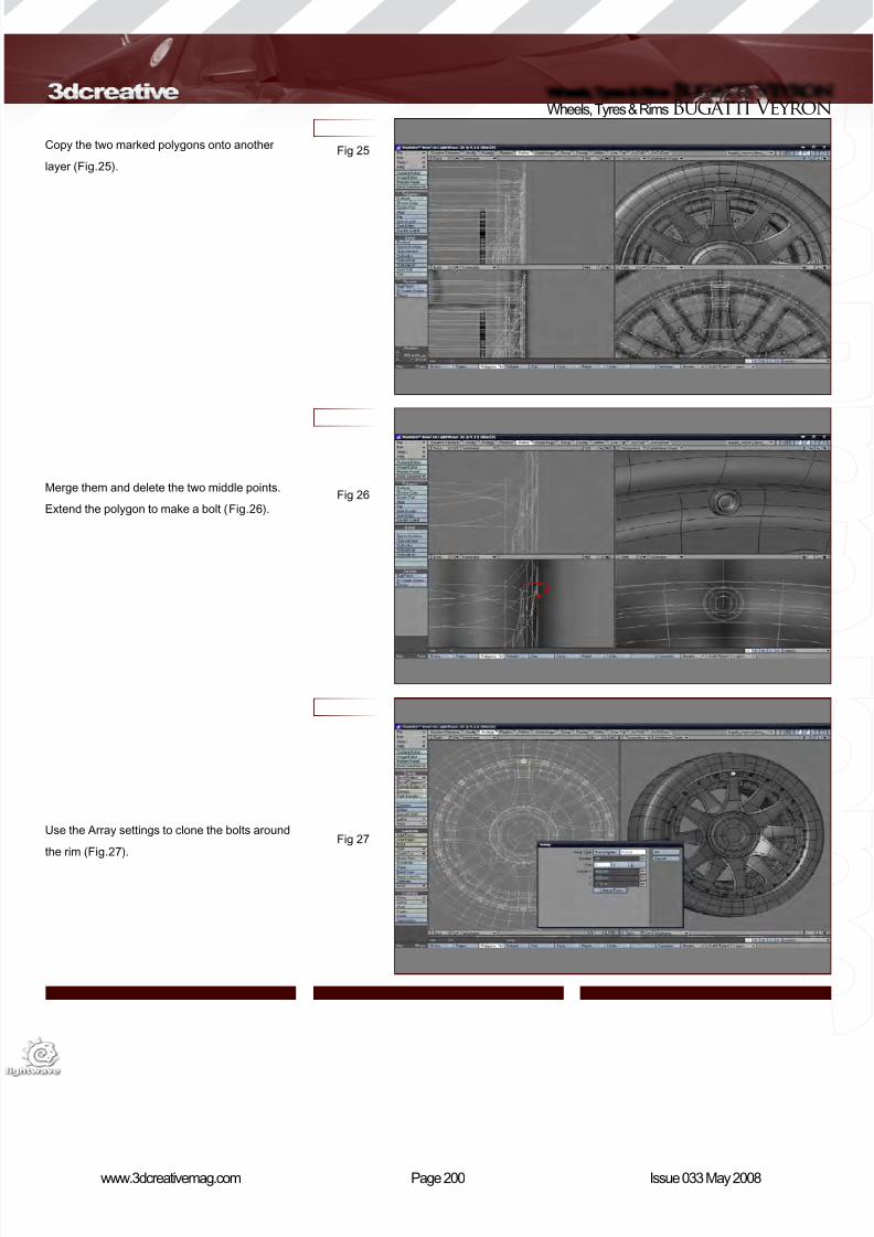
8/10/2019 3DCreative Magazine Issue 033 May 2008
http://slidepdf.com/reader/full/3dcreative-magazine-issue-033-may-2008 168/224
Page 200www.3dcreativemag.com Issue 033 May 2008
Wheels, Tyres & Rims Bugatti Veyron
Copy the two marked polygons onto another
layer (Fig.25).
Merge them and delete the two middle points.
Extend the polygon to make a bolt (Fig.26).
Use the Array settings to clone the bolts around
the rim (Fig.27).
Fig 25
Fig 26
Fig 27
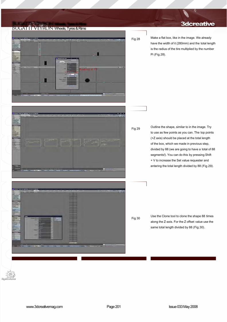
8/10/2019 3DCreative Magazine Issue 033 May 2008
http://slidepdf.com/reader/full/3dcreative-magazine-issue-033-may-2008 169/224
Page 201www.3dcreativemag.com Issue 033 May 2008
Bugatti Veyron Wheels, Tyres & Rims
Make a at box, like in the image. We already
have the width of it (280mm) and the total length
is the radius of the tire multiplied by the number
Pi (Fig.28).
Outline the shape, similar to in the image. Try
to use as few points as you can. The top points
(+Z axis) should be placed at the total length
of the box, which we made in previous step,
divided by 88 (we are going to have a total of 88
segments!). You can do this by pressing Shift
+ V to increase the Set value requester and
entering the total length divided by 88 (Fig.29).
Use the Clone tool to clone the shape 88 times
along the Z-axis. For the Z offset value use the
same total length divided by 88 (Fig.30).
Fig 28
Fig 29
Fig 30

8/10/2019 3DCreative Magazine Issue 033 May 2008
http://slidepdf.com/reader/full/3dcreative-magazine-issue-033-may-2008 170/224
Page 202www.3dcreativemag.com Issue 033 May 2008
Wheels, Tyres & Rims Bugatti Veyron
Merge the points and bevel up the polygons by
4mm (Fig.31).
In front view, use the Bend tool to bend all
polygons by 360 degrees (Fig.32).
Taper the end polygons so that they match with
the back tyre (Fig.33).
Fig 31
Fig 32
Fig 33

8/10/2019 3DCreative Magazine Issue 033 May 2008
http://slidepdf.com/reader/full/3dcreative-magazine-issue-033-may-2008 171/224
Page 203www.3dcreativemag.com Issue 033 May 2008
Bugatti Veyron Wheels, Tyres & Rims
You may need to do some ne adjustments so
that all the parts t together! (Fig.34)
Select the polygons shown in the image and
copy them onto another layer. Use the Knife tool
to cut how the red lines show you in the image.
Select the front points to make two polygons,
marked green in image, and delete the rest of it
(polygons going along the X-axis or inside the
tyre) (Fig.35).
Cut the polygons in half where the red line is.
Add two more cuts at the ends to make the
shape sharper. Extend it out and move the
middle points inside a fraction so they match the
roundness of the rim part (Fig.36).
Fig 34
Fig 35
Fig 36

8/10/2019 3DCreative Magazine Issue 033 May 2008
http://slidepdf.com/reader/full/3dcreative-magazine-issue-033-may-2008 172/224

8/10/2019 3DCreative Magazine Issue 033 May 2008
http://slidepdf.com/reader/full/3dcreative-magazine-issue-033-may-2008 173/224
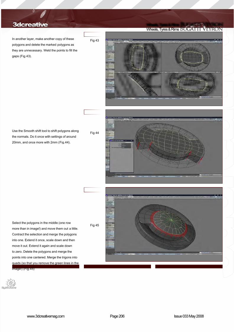
8/10/2019 3DCreative Magazine Issue 033 May 2008
http://slidepdf.com/reader/full/3dcreative-magazine-issue-033-may-2008 174/224
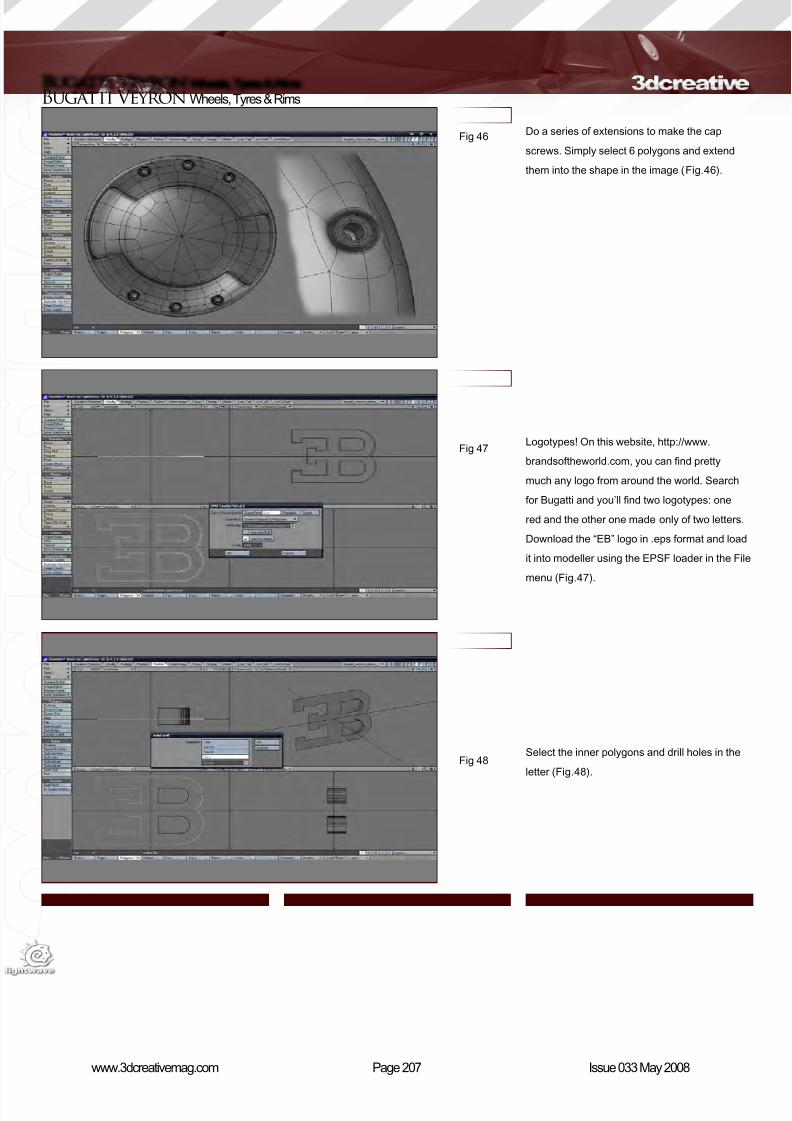
8/10/2019 3DCreative Magazine Issue 033 May 2008
http://slidepdf.com/reader/full/3dcreative-magazine-issue-033-may-2008 175/224
Page 207www.3dcreativemag.com Issue 033 May 2008
Bugatti Veyron Wheels, Tyres & Rims
Do a series of extensions to make the cap
screws. Simply select 6 polygons and extend
them into the shape in the image (Fig.46).
Logotypes! On this website, http://www.
brandsoftheworld.com, you can nd pretty
much any logo from around the world. Search
for Bugatti and you’ll nd two logotypes: one
red and the other one made only of two letters.
Download the “EB” logo in .eps format and load
it into modeller using the EPSF loader in the File
menu (Fig.47).
Select the inner polygons and drill holes in the
letter (Fig.48).
Fig 46
Fig 47
Fig 48
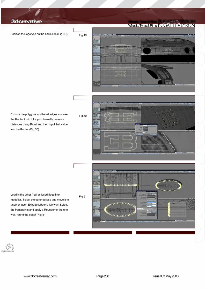
8/10/2019 3DCreative Magazine Issue 033 May 2008
http://slidepdf.com/reader/full/3dcreative-magazine-issue-033-may-2008 176/224
Page 208www.3dcreativemag.com Issue 033 May 2008
Wheels, Tyres & Rims Bugatti Veyron
Position the logotype on the back side (Fig.49).
Extrude the polygons and bevel edges – or use
the Router to do it for you. I usually measure
distances using Bevel and then input that value
into the Router (Fig.50).
Load in the other (red eclipsed) logo into
modeller. Select the outer eclipse and move it to
another layer. Extrude it back a fair way. Select
the front points and apply a Rounder to them to,
well, round the edge! (Fig.51)
Fig 49
Fig 50
Fig 51
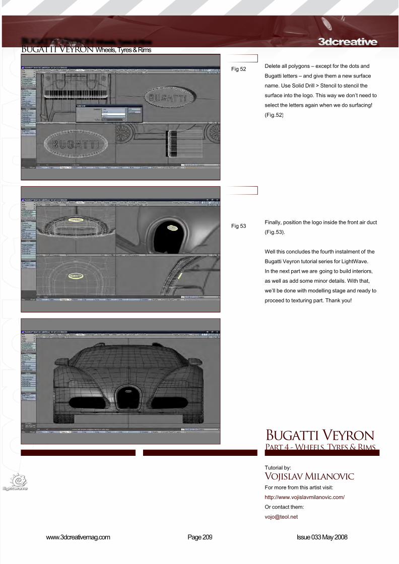
8/10/2019 3DCreative Magazine Issue 033 May 2008
http://slidepdf.com/reader/full/3dcreative-magazine-issue-033-may-2008 177/224
Page 209www.3dcreativemag.com Issue 033 May 2008
Bugatti Veyron Wheels, Tyres & Rims
Fig 52
Fig 53
Delete all polygons – except for the dots and
Bugatti letters – and give them a new surface
name. Use Solid Drill > Stencil to stencil the
surface into the logo. This way we don’t need to
select the letters again when we do surfacing!
(Fig.52)
Finally, position the logo inside the front air duct
(Fig.53).
Well this concludes the fourth instalment of the
Bugatti Veyron tutorial series for LightWave.
In the next part we are going to build interiors,
as well as add some minor details. With that,
we’ll be done with modelling stage and ready to
proceed to texturing part. Thank you!
Bugatti Veyron Part 4 - Wheels, Tyres & Rims
Tutorial by:
Vojislav MilanovicFor more from this artist visit:
http://www.vojislavmilanovic.com/
Or contact them:
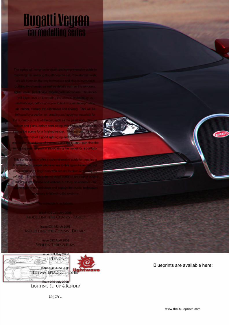
8/10/2019 3DCreative Magazine Issue 033 May 2008
http://slidepdf.com/reader/full/3dcreative-magazine-issue-033-may-2008 178/224
The series will cover an in-depth and comprehensive guide to
modelling the amazing Bugatti Veyron car, from start to nish.
We will focus on the key techniques and stages involved in
building the chassis, as well as details such as the windows,
lights, vents, petrol caps, engine parts and so on. The series
will then move on to creating the wheels, including tyres
and hubcaps, before going on to building and incorporating
an interior, namely the dashboard and seating. This will be
followed by a section on creating and applying materials for
the numerous parts of the car, such as the paint work, chrome,
rubber and glass, before concluding with a tutorial devoted to
setting the scene for a nished render. The nal part will cover
the importance of a good lighting rig and light parameters, as
well as the importance of a camera and the integral part that the
rendering settings play in showcasing the model for a portfolio.
This series aims to offer a comprehensive guide for creating a
nished car to people who are new to this type of exercise, but
is not suitable for beginners who are not familiar with using 3D
software. The tutorials do not detail every single step of adding
individual edge loops and vertices, but they do endeavour to
outline each important stage and explain the crucial techniques
necessary to following the exercise.
The schedule is as follows:
Issue 029 January 2008
Modelling the Chassis - Basics
Issue 031 March 2008Modelling the Chassis - Details
Issue 032 April 2008
Wheels, Tyres & Rims
Issue 033 May 2008
Interior
Issue 034 June 2008
The Materials & Finishes
Issue 035 July 2008
Lighting Set up & Render
Enjoy ...
Bugatti Veyron car modelling series
www.the-blueprints.com
Blueprints are available here:
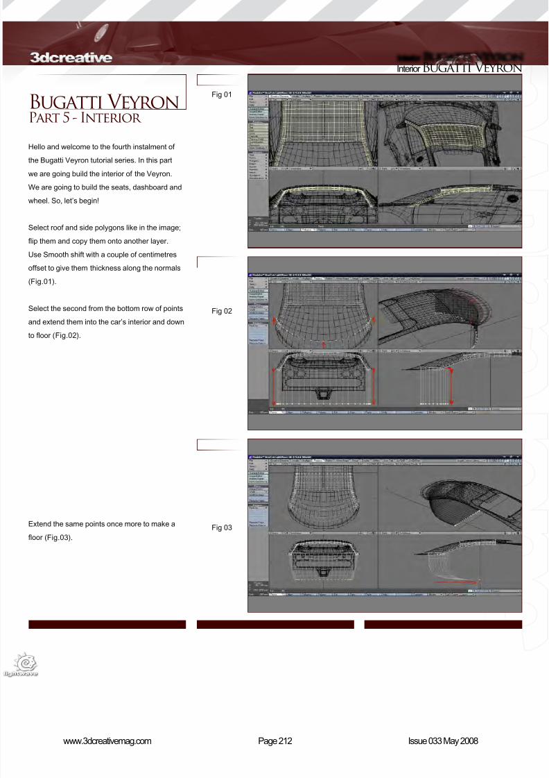
8/10/2019 3DCreative Magazine Issue 033 May 2008
http://slidepdf.com/reader/full/3dcreative-magazine-issue-033-may-2008 179/224
Page 212www.3dcreativemag.com Issue 033 May 2008
Interior Bugatti Veyron
Fig 01
Fig 02
Fig 03
Bugatti Veyron Part 5 - Interior
Hello and welcome to the fourth instalment of
the Bugatti Veyron tutorial series. In this part
we are going build the interior of the Veyron.
We are going to build the seats, dashboard and
wheel. So, let’s begin!
Select roof and side polygons like in the image;
ip them and copy them onto another layer.
Use Smooth shift with a couple of centimetres
offset to give them thickness along the normals
(Fig.01).
Select the second from the bottom row of points
and extend them into the car’s interior and down
to oor (Fig.02).
Extend the same points once more to make a
oor (Fig.03).
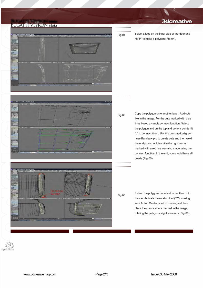
8/10/2019 3DCreative Magazine Issue 033 May 2008
http://slidepdf.com/reader/full/3dcreative-magazine-issue-033-may-2008 180/224
Page 213www.3dcreativemag.com Issue 033 May 2008
Bugatti Veyron Interior
Fig 04
Fig 05
Fig 06
Select a loop on the inner side of the door and
hit “P” to make a polygon (Fig.04).
Copy the polygon onto another layer. Add cuts
like in the image. For the cuts marked with blue
lines I used a simple connect function. Select
the polygon and on the top and bottom points hit
“L” to connect them. For the cuts marked green
I use Bandsaw pro to create cuts and then weld
the end points. A little cut in the right corner
marked with a red line was also made using the
connect function. In the end, you should have all
quads (Fig.05).
Extend the polygons once and move them into
the car. Activate the rotation tool (“Y”), making
sure Action Center is set to mouse, and then
place the cursor where marked in the image,
rotating the polygons slightly inwards (Fig.06).
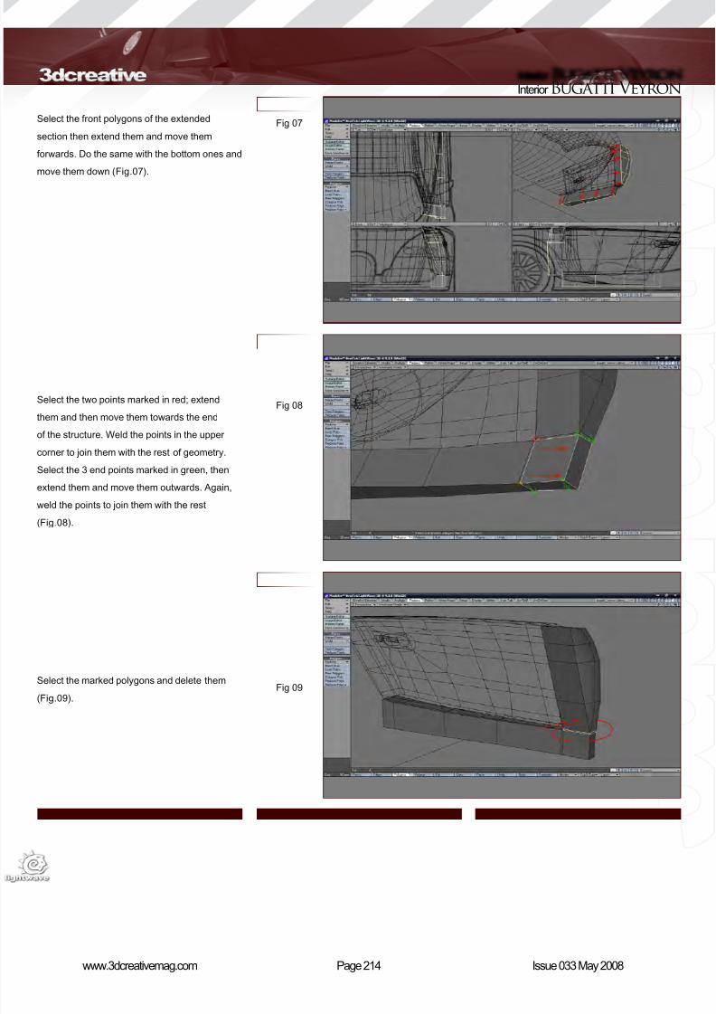
8/10/2019 3DCreative Magazine Issue 033 May 2008
http://slidepdf.com/reader/full/3dcreative-magazine-issue-033-may-2008 181/224
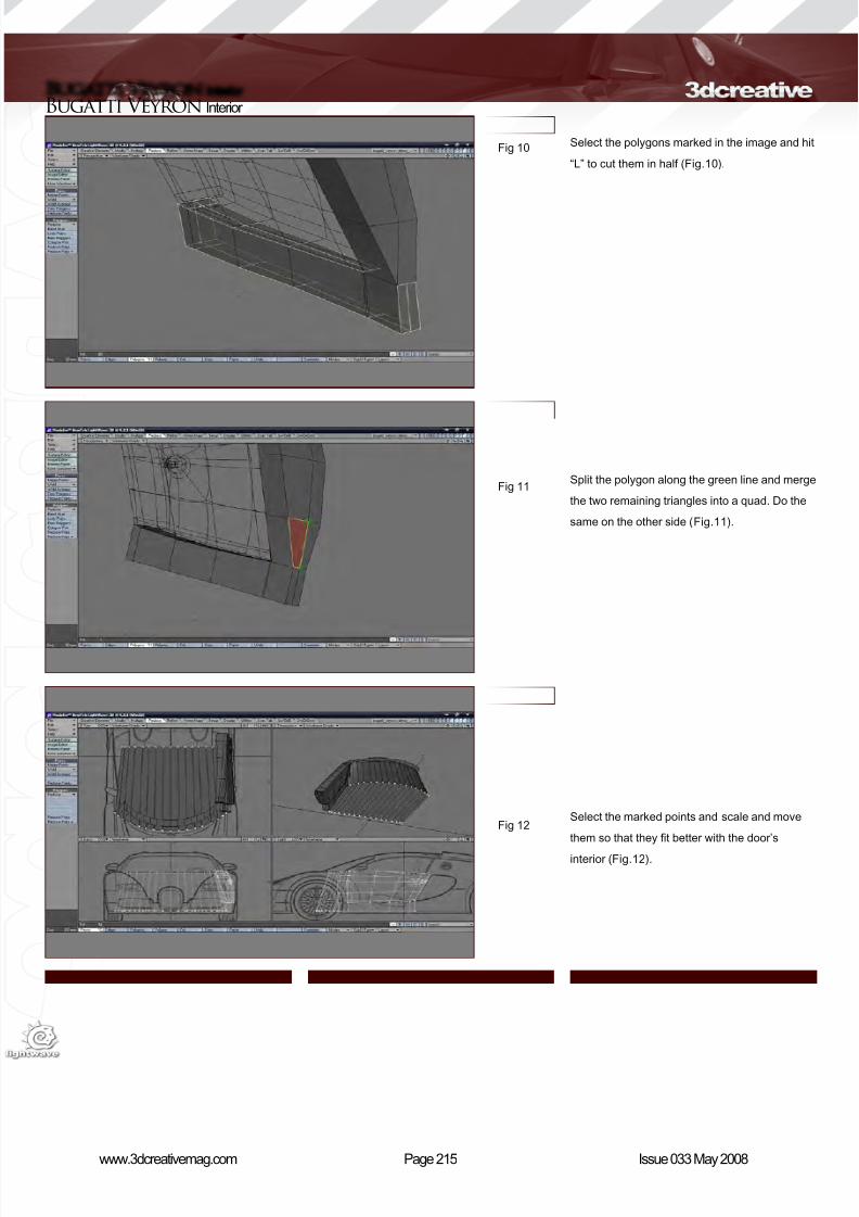
8/10/2019 3DCreative Magazine Issue 033 May 2008
http://slidepdf.com/reader/full/3dcreative-magazine-issue-033-may-2008 182/224
Page 215www.3dcreativemag.com Issue 033 May 2008
Bugatti Veyron Interior
Select the polygons marked in the image and hit
“L” to cut them in half (Fig.10).
Split the polygon along the green line and merge
the two remaining triangles into a quad. Do the
same on the other side (Fig.11).
Select the marked points and scale and move
them so that they t better with the door’s
interior (Fig.12).
Fig 10
Fig 11
Fig 12
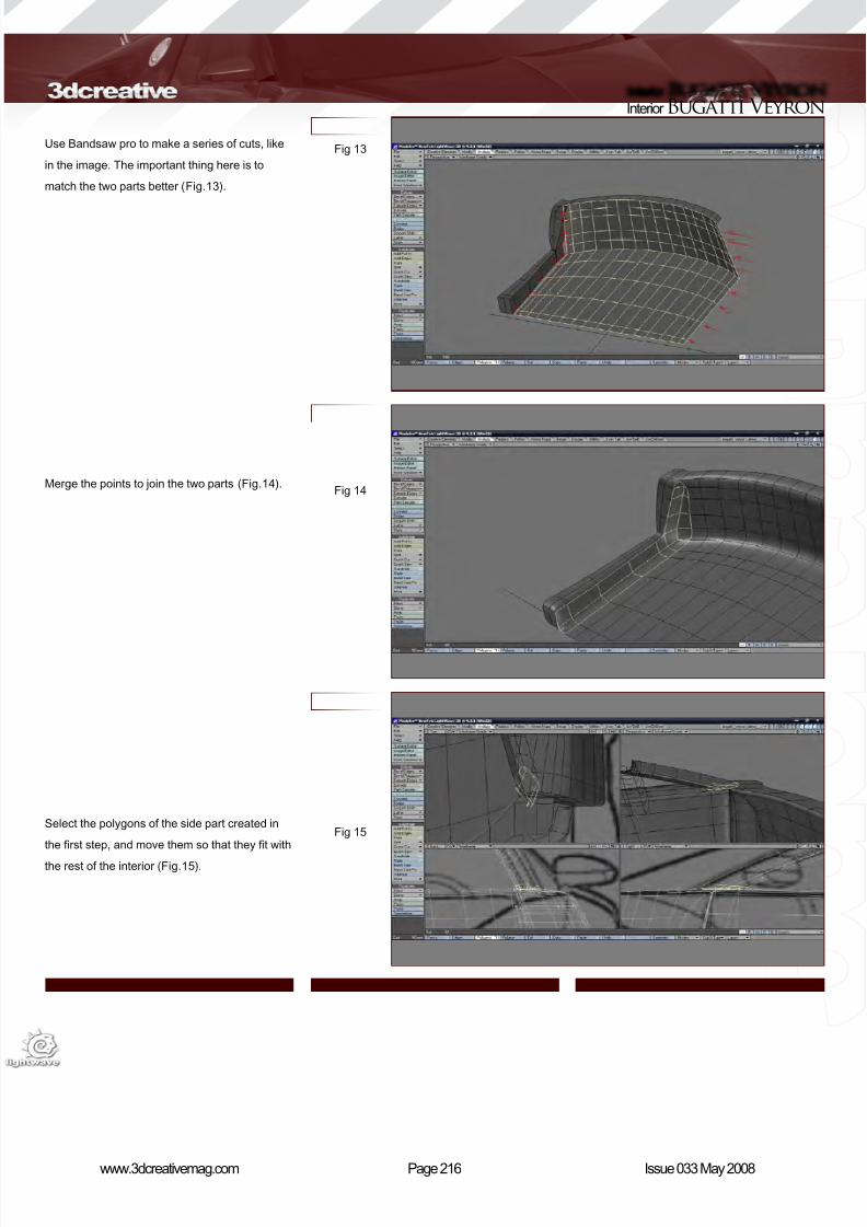
8/10/2019 3DCreative Magazine Issue 033 May 2008
http://slidepdf.com/reader/full/3dcreative-magazine-issue-033-may-2008 183/224
Page 216www.3dcreativemag.com Issue 033 May 2008
Interior Bugatti Veyron
Use Bandsaw pro to make a series of cuts, like
in the image. The important thing here is to
match the two parts better (Fig.13).
Merge the points to join the two parts (Fig.14).
Select the polygons of the side part created in
the rst step, and move them so that they t with
the rest of the interior (Fig.15).
Fig 13
Fig 14
Fig 15
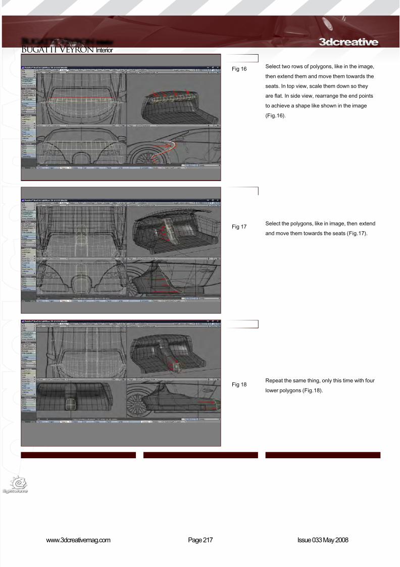
8/10/2019 3DCreative Magazine Issue 033 May 2008
http://slidepdf.com/reader/full/3dcreative-magazine-issue-033-may-2008 184/224
Page 217www.3dcreativemag.com Issue 033 May 2008
Bugatti Veyron Interior
Select two rows of polygons, like in the image,
then extend them and move them towards the
seats. In top view, scale them down so they
are at. In side view, rearrange the end points
to achieve a shape like shown in the image
(Fig.16).
Select the polygons, like in image, then extend
and move them towards the seats (Fig.17).
Repeat the same thing, only this time with four
lower polygons (Fig.18).
Fig 16
Fig 17
Fig 18
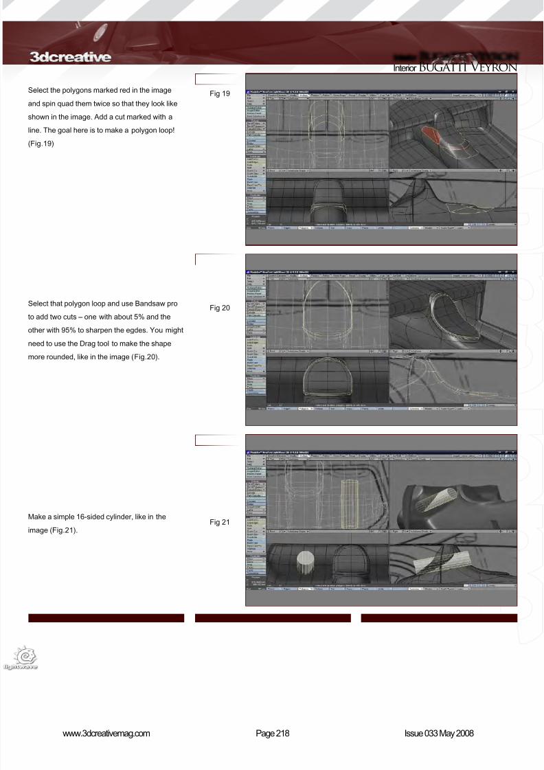
8/10/2019 3DCreative Magazine Issue 033 May 2008
http://slidepdf.com/reader/full/3dcreative-magazine-issue-033-may-2008 185/224
Page 218www.3dcreativemag.com Issue 033 May 2008
Interior Bugatti Veyron
Select the polygons marked red in the image
and spin quad them twice so that they look like
shown in the image. Add a cut marked with a
line. The goal here is to make a polygon loop!
(Fig.19)
Select that polygon loop and use Bandsaw pro
to add two cuts – one with about 5% and the
other with 95% to sharpen the egdes. You might
need to use the Drag tool to make the shape
more rounded, like in the image (Fig.20).
Make a simple 16-sided cylinder, like in the
image (Fig.21).
Fig 19
Fig 20
Fig 21
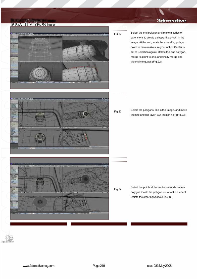
8/10/2019 3DCreative Magazine Issue 033 May 2008
http://slidepdf.com/reader/full/3dcreative-magazine-issue-033-may-2008 186/224
Page 219www.3dcreativemag.com Issue 033 May 2008
Bugatti Veyron Interior
Select the end polygon and make a series of
extensions to create a shape like shown in the
image. At the end, scale the extending polygon
down to zero (make sure your Action Center is
set to Selection again). Delete the end polygon,
merge its point to one, and nally merge end
trigons into quads (Fig.22).
Select the polygons, like in the image, and move
them to another layer. Cut them in half (Fig.23).
Select the points at the centre cut and create a
polygon. Scale the polygon up to make a wheel.
Delete the other polygons (Fig.24).
Fig 22
Fig 23
Fig 24
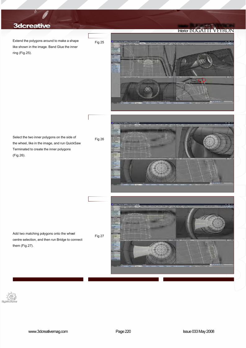
8/10/2019 3DCreative Magazine Issue 033 May 2008
http://slidepdf.com/reader/full/3dcreative-magazine-issue-033-may-2008 187/224
Page 220www.3dcreativemag.com Issue 033 May 2008
Interior Bugatti Veyron
Extend the polygons around to make a shape
like shown in the image. Band Glue the inner
ring (Fig.25).
Select the two inner polygons on the side of
the wheel, like in the image, and run QuickSaw
Terminated to create the inner polygons
(Fig.26).
Add two matching polygons onto the wheel
centre selection, and then run Bridge to connect
them (Fig.27).
Fig 25
Fig 26
Fig 27
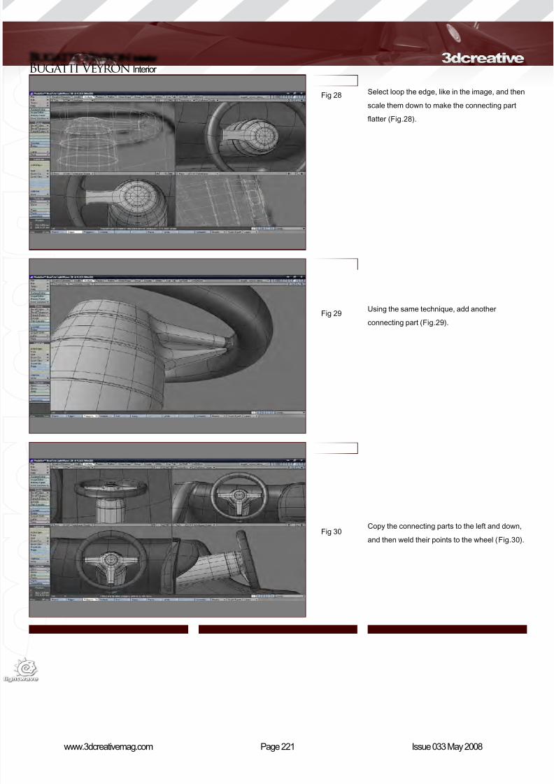
8/10/2019 3DCreative Magazine Issue 033 May 2008
http://slidepdf.com/reader/full/3dcreative-magazine-issue-033-may-2008 188/224
Page 221www.3dcreativemag.com Issue 033 May 2008
Bugatti Veyron Interior
Select loop the edge, like in the image, and then
scale them down to make the connecting part
atter (Fig.28).
Using the same technique, add another
connecting part (Fig.29).
Copy the connecting parts to the left and down,
and then weld their points to the wheel (Fig.30).
Fig 28
Fig 29
Fig 30

8/10/2019 3DCreative Magazine Issue 033 May 2008
http://slidepdf.com/reader/full/3dcreative-magazine-issue-033-may-2008 189/224
Page 222www.3dcreativemag.com Issue 033 May 2008
Interior Bugatti Veyron
Add the cuts onto the end and copy the EB logo
onto the centre of the wheel (Fig.31).
Add the cut in the middle and rene the shape
so it’s more square-like (Fig.32).
Make a disc, like in the image. Scale and rotate
it so that it ts on the surface. Make a series
of extensions to create the rim and the glass
surface of the clock (Fig.33).
Fig 31
Fig 32
Fig 33
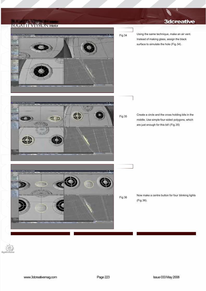
8/10/2019 3DCreative Magazine Issue 033 May 2008
http://slidepdf.com/reader/full/3dcreative-magazine-issue-033-may-2008 190/224
Page 223www.3dcreativemag.com Issue 033 May 2008
Bugatti Veyron Interior
Using the same technique, make an air vent.
Instead of making glass, assign the black
surface to simulate the hole (Fig.34).
Create a circle and the cross holding bits in the
middle. Use simple four-sided polygons, which
are just enough for this bit! (Fig.35)
Now make a centre button for four blinking lights
(Fig.36).
Fig 34
Fig 35
Fig 36
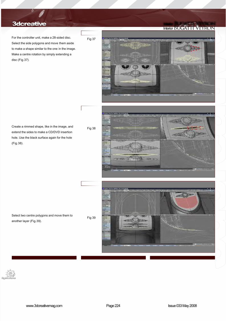
8/10/2019 3DCreative Magazine Issue 033 May 2008
http://slidepdf.com/reader/full/3dcreative-magazine-issue-033-may-2008 191/224
Page 224www.3dcreativemag.com Issue 033 May 2008
Interior Bugatti Veyron
For the controller unit, make a 28-sided disc.
Select the side polygons and move them aside
to make a shape similar to the one in the image.
Make a centre rotation by simply extending a
disc (Fig.37).
Create a rimmed shape, like in the image, and
extend the sides to make a CD/DVD insertion
hole. Use the black surface again for the hole
(Fig.38).
Select two centre polygons and move them to
another layer (Fig.39).
Fig 37
Fig 38
Fig 39
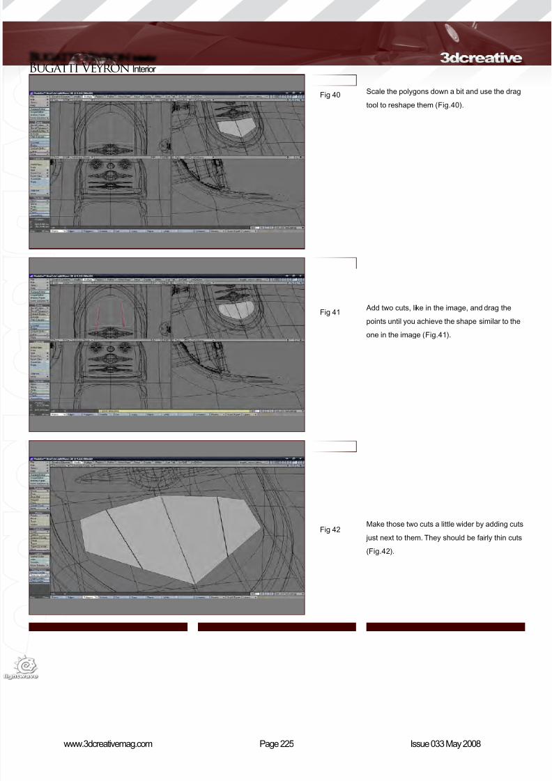
8/10/2019 3DCreative Magazine Issue 033 May 2008
http://slidepdf.com/reader/full/3dcreative-magazine-issue-033-may-2008 192/224
Page 225www.3dcreativemag.com Issue 033 May 2008
Bugatti Veyron Interior
Scale the polygons down a bit and use the drag
tool to reshape them (Fig.40).
Add two cuts, like in the image, and drag the
points until you achieve the shape similar to the
one in the image (Fig.41).
Make those two cuts a little wider by adding cuts
just next to them. They should be fairly thin cuts
(Fig.42).
Fig 40
Fig 41
Fig 42
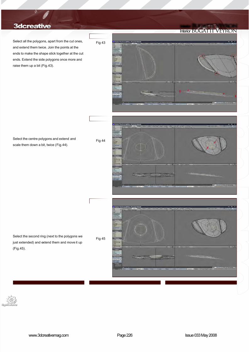
8/10/2019 3DCreative Magazine Issue 033 May 2008
http://slidepdf.com/reader/full/3dcreative-magazine-issue-033-may-2008 193/224
Page 226www.3dcreativemag.com Issue 033 May 2008
Interior Bugatti Veyron
Select all the polygons, apart from the cut ones,
and extend them twice. Join the points at the
ends to make the shape stick together at the cut
ends. Extend the side polygons once more and
raise them up a bit (Fig.43).
Select the centre polygons and extend and
scale them down a bit, twice (Fig.44).
Select the second ring (next to the polygons we
just extended) and extend them and move it up
(Fig.45).
Fig 43
Fig 44
Fig 45
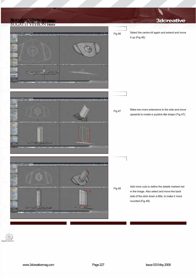
8/10/2019 3DCreative Magazine Issue 033 May 2008
http://slidepdf.com/reader/full/3dcreative-magazine-issue-033-may-2008 194/224
Page 227www.3dcreativemag.com Issue 033 May 2008
Bugatti Veyron Interior
Fig 46
Fig 47
Fig 48
Select the centre bit again and extend and move
it up (Fig.46).
Make two more extensions to the side and move
upwards to create a joystick-like shape (Fig.47).
Add more cuts to dene the details marked red
in the image. Also select and move the back
side of the stick down a little, to make it more
rounded (Fig.48).
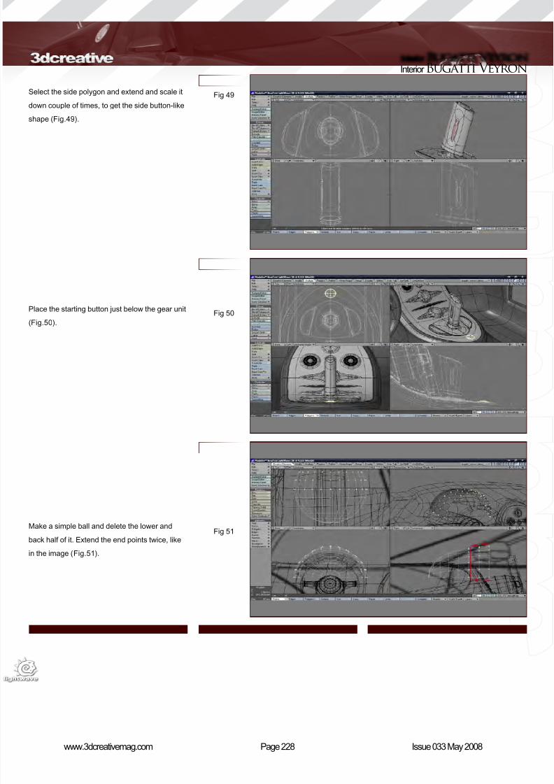
8/10/2019 3DCreative Magazine Issue 033 May 2008
http://slidepdf.com/reader/full/3dcreative-magazine-issue-033-may-2008 195/224
Page 228www.3dcreativemag.com Issue 033 May 2008
Interior Bugatti Veyron
Fig 49
Fig 50
Fig 51
Select the side polygon and extend and scale it
down couple of times, to get the side button-like
shape (Fig.49).
Place the starting button just below the gear unit
(Fig.50).
Make a simple ball and delete the lower and
back half of it. Extend the end points twice, like
in the image (Fig.51).
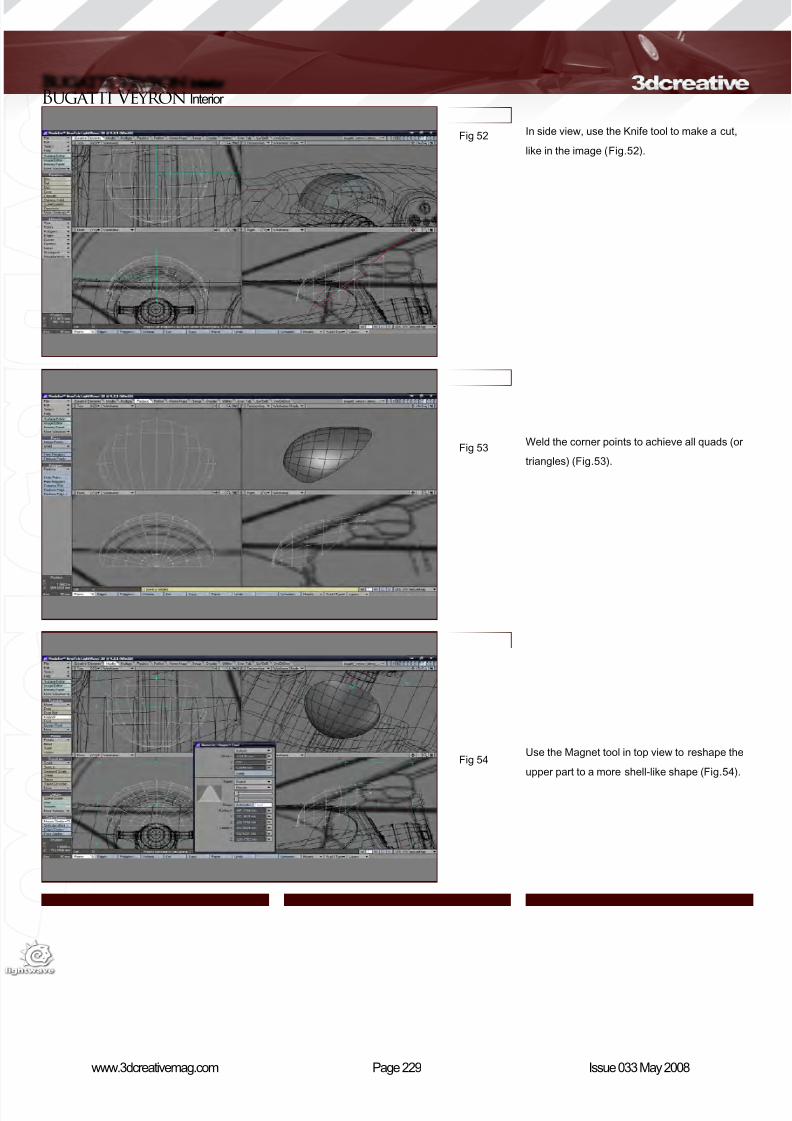
8/10/2019 3DCreative Magazine Issue 033 May 2008
http://slidepdf.com/reader/full/3dcreative-magazine-issue-033-may-2008 196/224
Page 229www.3dcreativemag.com Issue 033 May 2008
Bugatti Veyron Interior
Fig 52
Fig 53
Fig 54
In side view, use the Knife tool to make a cut,
like in the image (Fig.52).
Weld the corner points to achieve all quads (or
triangles) (Fig.53).
Use the Magnet tool in top view to reshape the
upper part to a more shell-like shape (Fig.54).
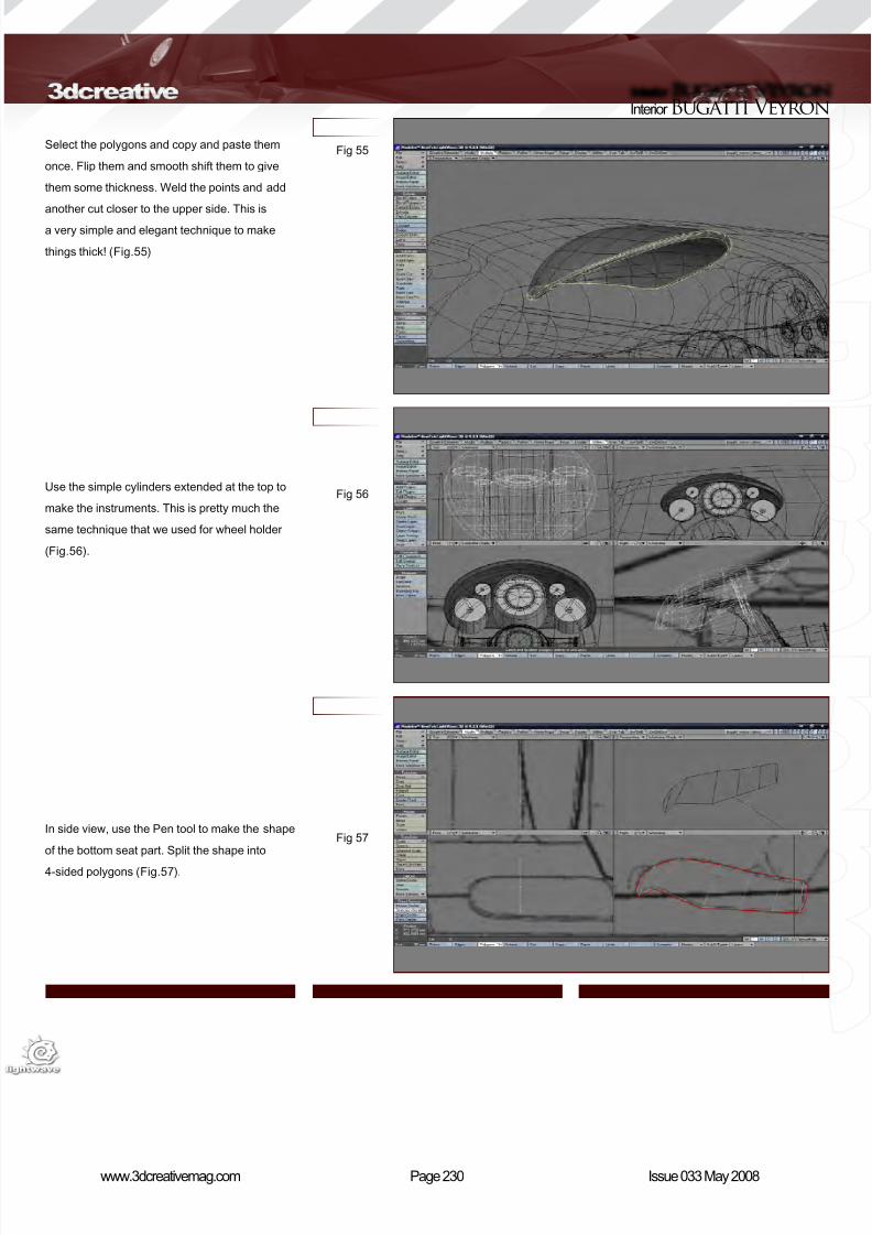
8/10/2019 3DCreative Magazine Issue 033 May 2008
http://slidepdf.com/reader/full/3dcreative-magazine-issue-033-may-2008 197/224
Page 230www.3dcreativemag.com Issue 033 May 2008
Interior Bugatti Veyron
Fig 55
Fig 56
Fig 57
Select the polygons and copy and paste them
once. Flip them and smooth shift them to give
them some thickness. Weld the points and add
another cut closer to the upper side. This is
a very simple and elegant technique to make
things thick! (Fig.55)
Use the simple cylinders extended at the top to
make the instruments. This is pretty much the
same technique that we used for wheel holder
(Fig.56).
In side view, use the Pen tool to make the shape
of the bottom seat part. Split the shape into
4-sided polygons (Fig.57).
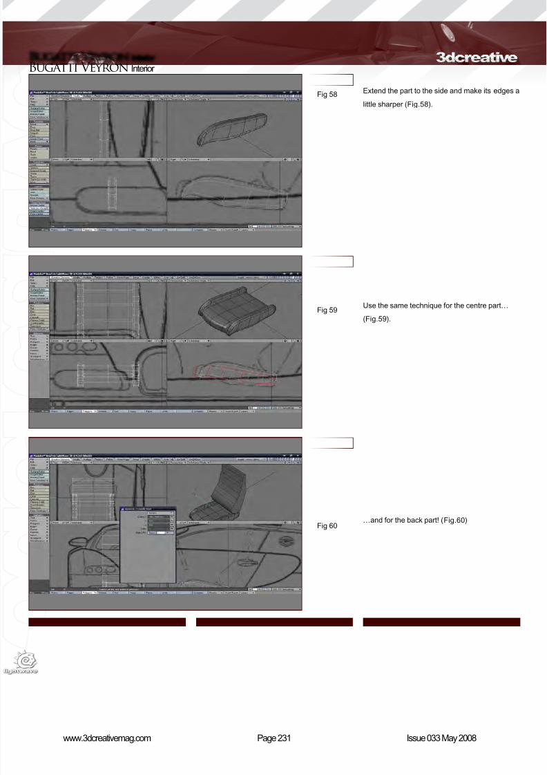
8/10/2019 3DCreative Magazine Issue 033 May 2008
http://slidepdf.com/reader/full/3dcreative-magazine-issue-033-may-2008 198/224
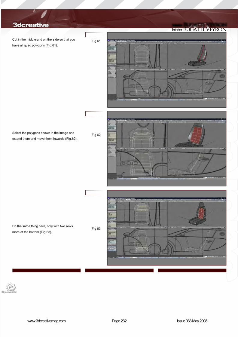
8/10/2019 3DCreative Magazine Issue 033 May 2008
http://slidepdf.com/reader/full/3dcreative-magazine-issue-033-may-2008 199/224
Page 232www.3dcreativemag.com Issue 033 May 2008
Interior Bugatti Veyron
Fig 61
Fig 62
Fig 63
Cut in the middle and on the side so that you
have all quad polygons (Fig.61).
Select the polygons shown in the image and
extend them and move them inwards (Fig.62).
Do the same thing here, only with two rows
more at the bottom (Fig.63).
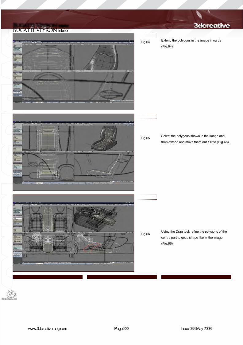
8/10/2019 3DCreative Magazine Issue 033 May 2008
http://slidepdf.com/reader/full/3dcreative-magazine-issue-033-may-2008 200/224
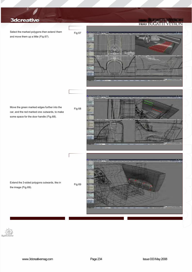
8/10/2019 3DCreative Magazine Issue 033 May 2008
http://slidepdf.com/reader/full/3dcreative-magazine-issue-033-may-2008 201/224
Page 234www.3dcreativemag.com Issue 033 May 2008
Interior Bugatti Veyron
Fig 67
Fig 68
Fig 69
Select the marked polygons then extend them
and move them up a little (Fig.67).
Move the green marked edges further into the
car, and the red marked one outwards, to make
some space for the door handle (Fig.68).
Extend the 3-sided polygons outwards, like in
the image (Fig.69).
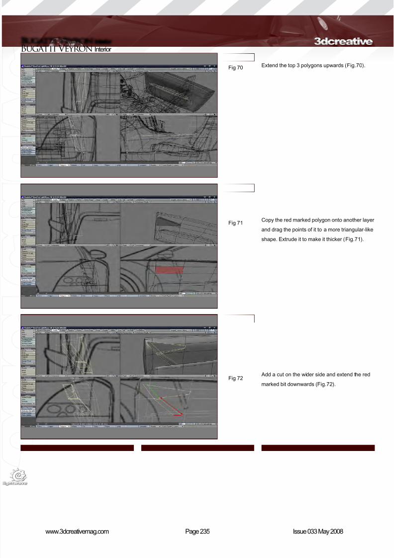
8/10/2019 3DCreative Magazine Issue 033 May 2008
http://slidepdf.com/reader/full/3dcreative-magazine-issue-033-may-2008 202/224
Page 235www.3dcreativemag.com Issue 033 May 2008
Bugatti Veyron Interior
Fig 70
Fig 71
Fig 72
Extend the top 3 polygons upwards (Fig.70).
Copy the red marked polygon onto another layer
and drag the points of it to a more triangular-like
shape. Extrude it to make it thicker (Fig.71).
Add a cut on the wider side and extend the red
marked bit downwards (Fig.72).
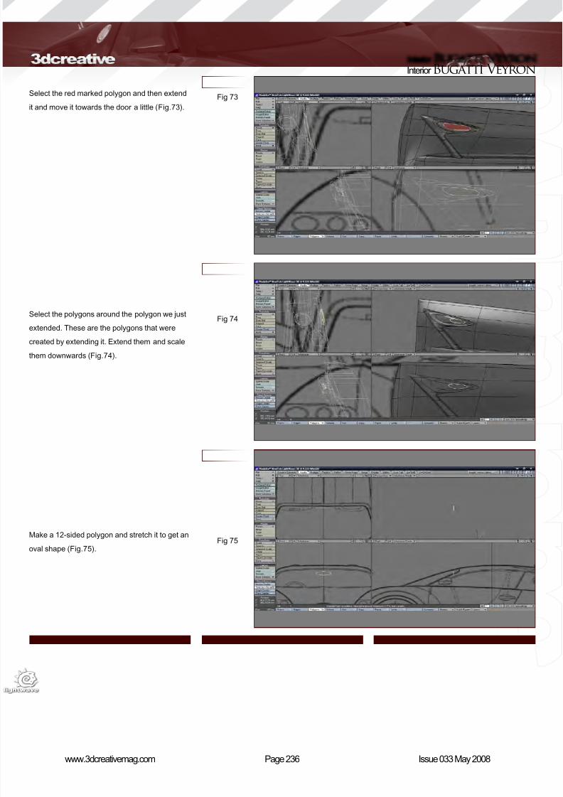
8/10/2019 3DCreative Magazine Issue 033 May 2008
http://slidepdf.com/reader/full/3dcreative-magazine-issue-033-may-2008 203/224
Page 236www.3dcreativemag.com Issue 033 May 2008
Interior Bugatti Veyron
Fig 73
Fig 74
Fig 75
Select the red marked polygon and then extend
it and move it towards the door a little (Fig.73).
Select the polygons around the polygon we just
extended. These are the polygons that were
created by extending it. Extend them and scale
them downwards (Fig.74).
Make a 12-sided polygon and stretch it to get an
oval shape (Fig.75).
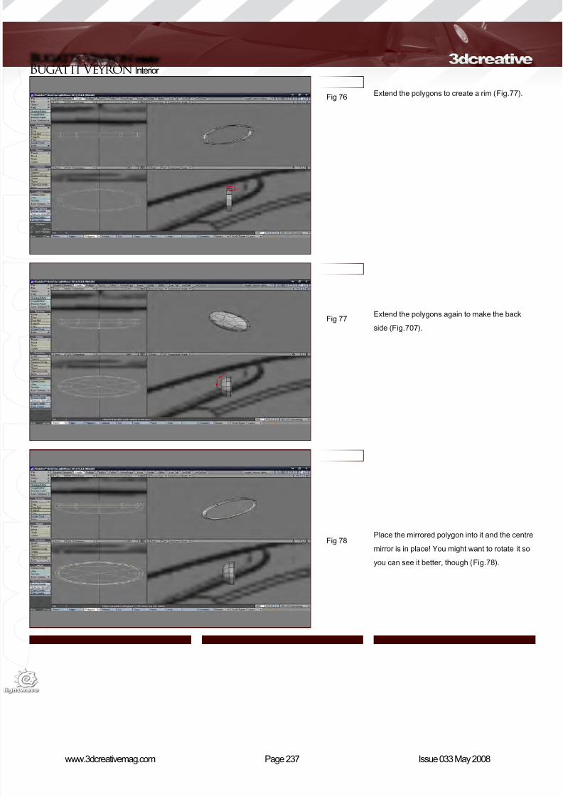
8/10/2019 3DCreative Magazine Issue 033 May 2008
http://slidepdf.com/reader/full/3dcreative-magazine-issue-033-may-2008 204/224
Page 237www.3dcreativemag.com Issue 033 May 2008
Bugatti Veyron Interior
Fig 76
Fig 77
Fig 78
Extend the polygons to create a rim (Fig.77).
Extend the polygons again to make the back
side (Fig.707).
Place the mirrored polygon into it and the centre
mirror is in place! You might want to rotate it so
you can see it better, though (Fig.78).
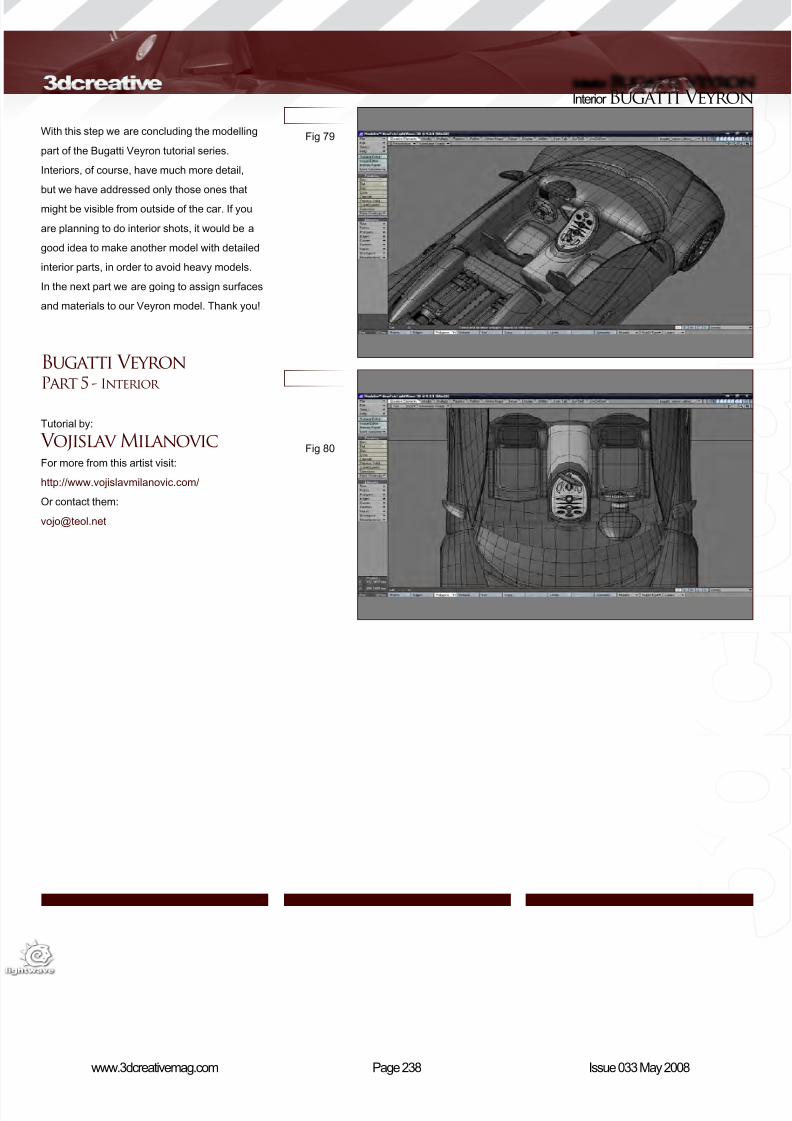
8/10/2019 3DCreative Magazine Issue 033 May 2008
http://slidepdf.com/reader/full/3dcreative-magazine-issue-033-may-2008 205/224
Page 238www.3dcreativemag.com Issue 033 May 2008
Interior Bugatti Veyron
Fig 79
Fig 80
With this step we are concluding the modelling
part of the Bugatti Veyron tutorial series.
Interiors, of course, have much more detail,
but we have addressed only those ones that
might be visible from outside of the car. If you
are planning to do interior shots, it would be a
good idea to make another model with detailed
interior parts, in order to avoid heavy models.
In the next part we are going to assign surfaces
and materials to our Veyron model. Thank you!
Bugatti VeyronPart 5 - Interior
Tutorial by:
Vojislav MilanovicFor more from this artist visit:
http://www.vojislavmilanovic.com/
Or contact them:
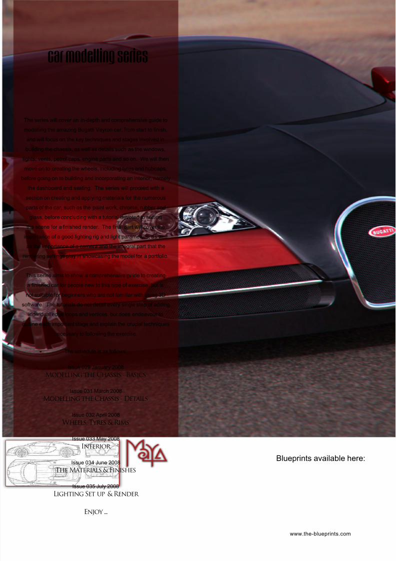
8/10/2019 3DCreative Magazine Issue 033 May 2008
http://slidepdf.com/reader/full/3dcreative-magazine-issue-033-may-2008 206/224
The series will cover an in-depth and comprehensive guide to
modelling the amazing Bugatti Veyron car, from start to nish,
and will focus on the key techniques and stages involved in
building the chassis, as well as details such as the windows,
lights, vents, petrol caps, engine parts and so on. We will then
move on to creating the wheels, including tyres and hubcaps,
before going on to building and incorporating an interior, namely
the dashboard and seating. The series will proceed with a
section on creating and applying materials for the numerous
parts of the car, such as the paint work, chrome, rubber and
glass, before concluding with a tutorial devoted to setting
the scene for a nished render. The nal part will cover the
importance of a good lighting rig and light parameters, as well
as the importance of a camera and the integral part that the
rendering settings play in showcasing the model for a portfolio.
This series aims to show a comprehensive guide to creating
a nished car for people new to this type of exercise, but is
not suitable for beginners who are not familiar with using 3D
software. The tutorials do not detail every single step of adding
individual edge loops and vertices, but does endeavour to
outline each important stage and explain the crucial techniques
necessary to following the exercise.
The schedule is as follows:
Issue 029 January 2008
Modelling the Chassis - Basics
Issue 031 March 2008Modelling the Chassis - Details
Issue 032 April 2008
Wheels, Tyres & Rims
Issue 033 May 2008
Interior
Issue 034 June 2008
The Materials & Finishes
Issue 035 July 2008
Lighting Set up & Render
Enjoy ...
car modelling series
www.the-blueprints.com
Blueprints available here:
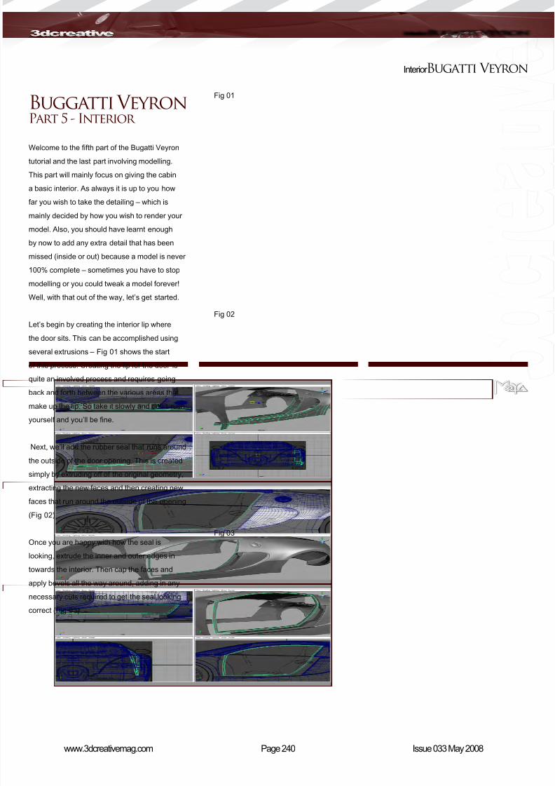
8/10/2019 3DCreative Magazine Issue 033 May 2008
http://slidepdf.com/reader/full/3dcreative-magazine-issue-033-may-2008 207/224
Page 240www.3dcreativemag.com Issue 033 May 2008
Interior Bugatti Veyron
Fig 01
Fig 02
Fig 03
Buggatti VeyronPart 5 - Interior
Welcome to the fth part of the Bugatti Veyron
tutorial and the last part involving modelling.
This part will mainly focus on giving the cabin
a basic interior. As always it is up to you how
far you wish to take the detailing – which is
mainly decided by how you wish to render your
model. Also, you should have learnt enough
by now to add any extra detail that has been
missed (inside or out) because a model is never
100% complete – sometimes you have to stop
modelling or you could tweak a model forever!
Well, with that out of the way, let’s get started.
Let’s begin by creating the interior lip where
the door sits. This can be accomplished using
several extrusions – Fig 01 shows the start
of this process. Creating the lip for the door is
quite an involved process and requires going
back and forth between the various areas that
make up the lip. So take it slowly and don’t rush
yourself and you’ll be ne.
Next, we’ll add the rubber seal that runs around
the outside of the door opening. This is created
simply by extruding off of the original geometry,
extracting the new faces and then creating new
faces that run around the outside of the opening
(Fig 02).
Once you are happy with how the seal is
looking, extrude the inner and outer edges in
towards the interior. Then cap the faces and
apply bevels all the way around, adding in any
necessary cuts required to get the seal looking
correct (Fig 03).
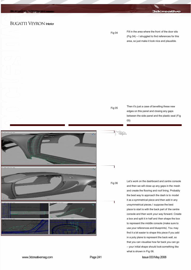
8/10/2019 3DCreative Magazine Issue 033 May 2008
http://slidepdf.com/reader/full/3dcreative-magazine-issue-033-may-2008 208/224
Page 241www.3dcreativemag.com Issue 033 May 2008
Bugatti Veyron Interior
Fig 04
Fig 05
Fig 06
Fill in the area where the front of the door sits
(Fig 04) – I struggled to nd references for this
area, so just make it look nice and plausible.
Then it’s just a case of bevelling these new
edges on this panel and closing any gaps
between the side panel and the plastic seal (Fig
05)
Let’s work on the dashboard and centre console
and then we will close up any gaps in the mesh
and create the ooring and roof lining. Probably
the best way to approach the dash is to model
it as a symmetrical piece and then add in any
unsymmetrical pieces. I suppose the best
place to start is with the back part of the centre
console and then work your way forward. Create
a box and split it in half and then shape the box
to represent the middle console (make sure to
use your references and blueprints). You may
nd it a bit easier to shape this piece if you add
in a poly plane to represent the back wall, so
that you can visualise how far back you can go
– your initial shape should look something like
what is shown in Fig 06.
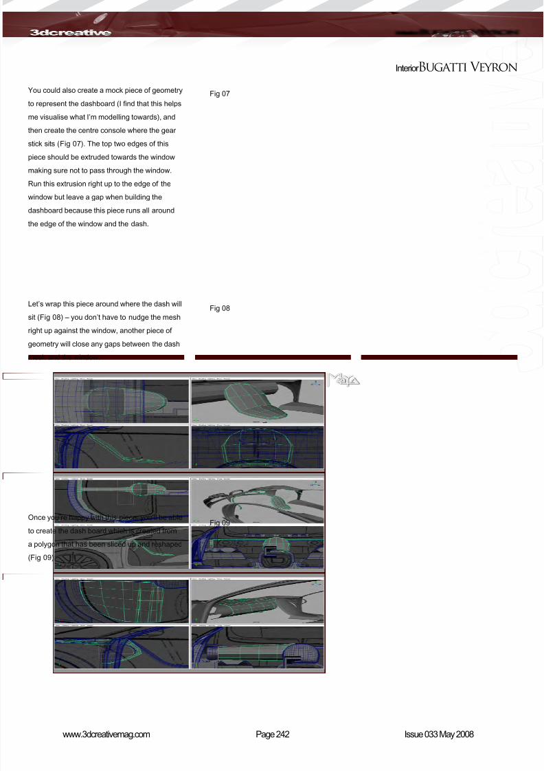
8/10/2019 3DCreative Magazine Issue 033 May 2008
http://slidepdf.com/reader/full/3dcreative-magazine-issue-033-may-2008 209/224
Page 242www.3dcreativemag.com Issue 033 May 2008
Interior Bugatti Veyron
You could also create a mock piece of geometry
to represent the dashboard (I nd that this helps
me visualise what I’m modelling towards), and
then create the centre console where the gear
stick sits (Fig 07). The top two edges of this
piece should be extruded towards the window
making sure not to pass through the window.
Run this extrusion right up to the edge of the
window but leave a gap when building the
dashboard because this piece runs all around
the edge of the window and the dash.
Let’s wrap this piece around where the dash will
sit (Fig 08) – you don’t have to nudge the mesh
right up against the window, another piece of
geometry will close any gaps between the dash
mesh and the window.
Once you’re happy with this piece, you’ll be able
to create the dash board which is created from
a polygon that has been sliced up and reshaped
(Fig 09).
Fig 07
Fig 08
Fig 09

8/10/2019 3DCreative Magazine Issue 033 May 2008
http://slidepdf.com/reader/full/3dcreative-magazine-issue-033-may-2008 210/224
Page 243www.3dcreativemag.com Issue 033 May 2008
Bugatti Veyron Interior
We’re only creating a basic interior for the sake
of this tutorial so just tuck it in towards the front
of the car and mirror it to the other side. Give
the geometry that runs around the dash some
thickness, create a new piece of geometry that
closes the gap where the door opens and create
a steering column out of a cylinder (Fig 10).
Create another cylinder for the steering wheel
holder and then create the steering wheel,
extruding the outer faces to create the three
spokes of the steering wheel (Fig 11).
To nish of the steering wheel, create a torus
and then just extrude faces out to close the gap
between the wheel and spokes (Fig 12).
Fig 10
Fig 11
Fig 12
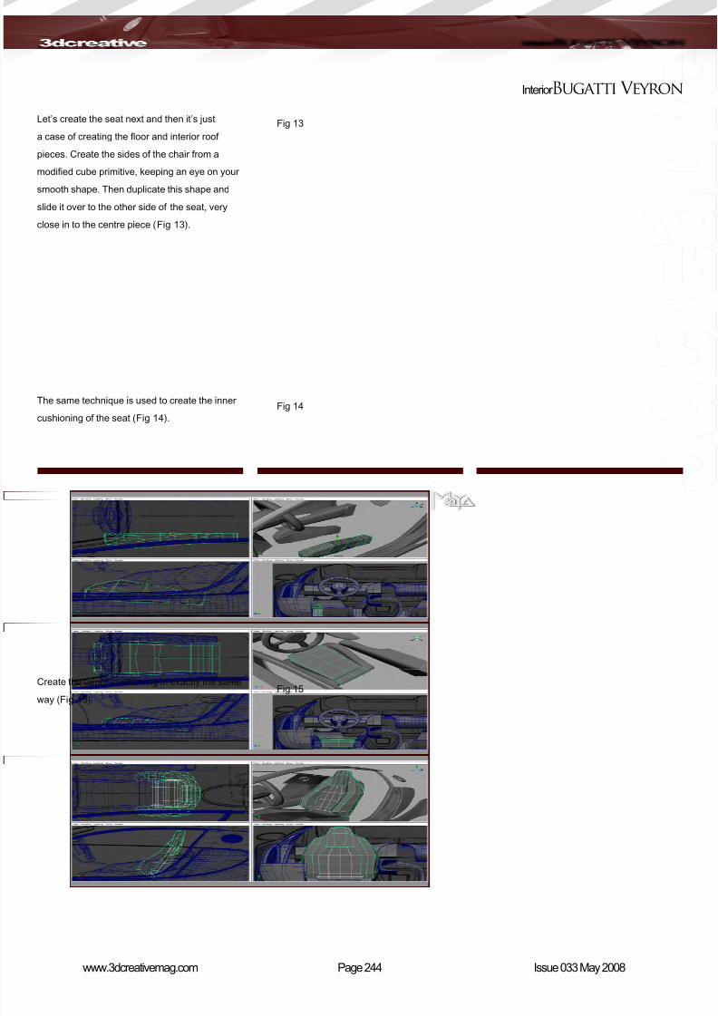
8/10/2019 3DCreative Magazine Issue 033 May 2008
http://slidepdf.com/reader/full/3dcreative-magazine-issue-033-may-2008 211/224
Page 244www.3dcreativemag.com Issue 033 May 2008
Interior Bugatti Veyron
Let’s create the seat next and then it’s just
a case of creating the oor and interior roof
pieces. Create the sides of the chair from a
modied cube primitive, keeping an eye on your
smooth shape. Then duplicate this shape and
slide it over to the other side of the seat, very
close in to the centre piece (Fig 13).
The same technique is used to create the inner
cushioning of the seat (Fig 14).
Create the upper cushioning in exactly the same
way (Fig 15).
Fig 13
Fig 14
Fig 15
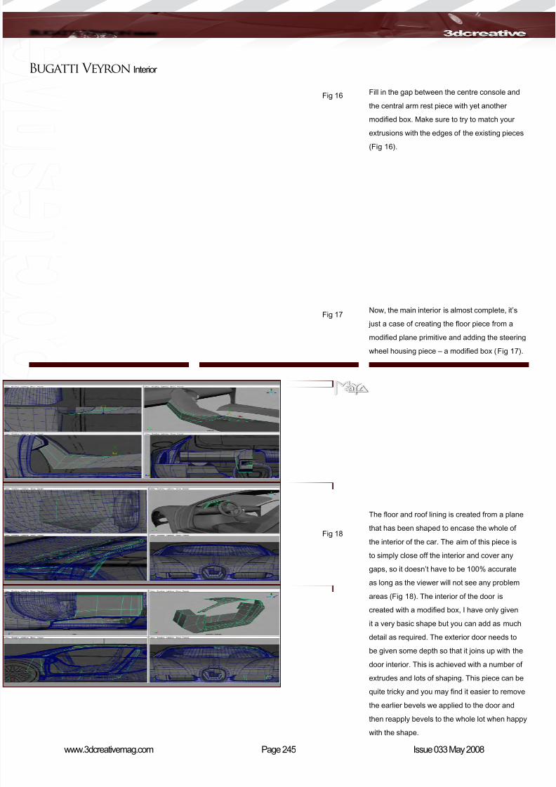
8/10/2019 3DCreative Magazine Issue 033 May 2008
http://slidepdf.com/reader/full/3dcreative-magazine-issue-033-may-2008 212/224
Page 245www.3dcreativemag.com Issue 033 May 2008
Bugatti Veyron Interior
Fill in the gap between the centre console and
the central arm rest piece with yet another
modied box. Make sure to try to match your
extrusions with the edges of the existing pieces
(Fig 16).
Now, the main interior is almost complete, it’s
just a case of creating the oor piece from a
modied plane primitive and adding the steering
wheel housing piece – a modied box (Fig 17).
The oor and roof lining is created from a plane
that has been shaped to encase the whole of
the interior of the car. The aim of this piece is
to simply close off the interior and cover any
gaps, so it doesn’t have to be 100% accurate
as long as the viewer will not see any problem
areas (Fig 18). The interior of the door is
created with a modied box, I have only given
it a very basic shape but you can add as much
detail as required. The exterior door needs to
be given some depth so that it joins up with the
door interior. This is achieved with a number of
extrudes and lots of shaping. This piece can be
quite tricky and you may nd it easier to remove
the earlier bevels we applied to the door and
then reapply bevels to the whole lot when happy
with the shape.
Fig 16
Fig 17
Fig 18
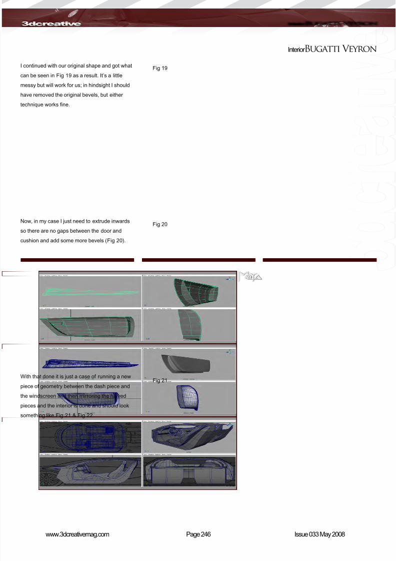
8/10/2019 3DCreative Magazine Issue 033 May 2008
http://slidepdf.com/reader/full/3dcreative-magazine-issue-033-may-2008 213/224
Page 246www.3dcreativemag.com Issue 033 May 2008
Interior Bugatti Veyron
I continued with our original shape and got what
can be seen in Fig 19 as a result. It’s a little
messy but will work for us; in hindsight I should
have removed the original bevels, but either
technique works ne.
Now, in my case I just need to extrude inwards
so there are no gaps between the door and
cushion and add some more bevels (Fig 20).
With that done it is just a case of running a new
piece of geometry between the dash piece and
the windscreen and then mirroring the halved
pieces and the interior is done and should look
something like Fig 21 & Fig 22.
Fig 19
Fig 20
Fig 21
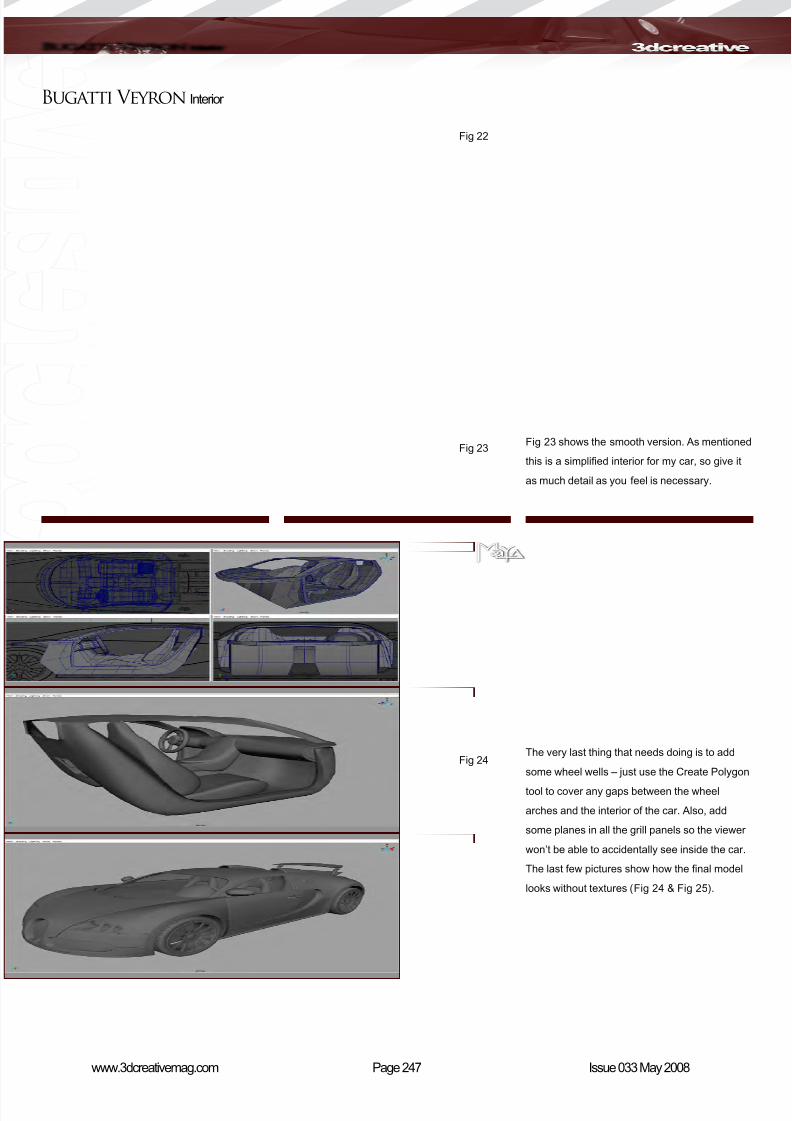
8/10/2019 3DCreative Magazine Issue 033 May 2008
http://slidepdf.com/reader/full/3dcreative-magazine-issue-033-may-2008 214/224

8/10/2019 3DCreative Magazine Issue 033 May 2008
http://slidepdf.com/reader/full/3dcreative-magazine-issue-033-may-2008 215/224
Page 248www.3dcreativemag.com Issue 033 May 2008
Interior Bugatti Veyron
Bugatti VeyronPart 5 - Interior
Tutorial by:
Andrew HobsonFor more from this artist, contact them:
Fig 25
8/10/2019 3DCreative Magazine Issue 033 May 2008
http://slidepdf.com/reader/full/3dcreative-magazine-issue-033-may-2008 216/224
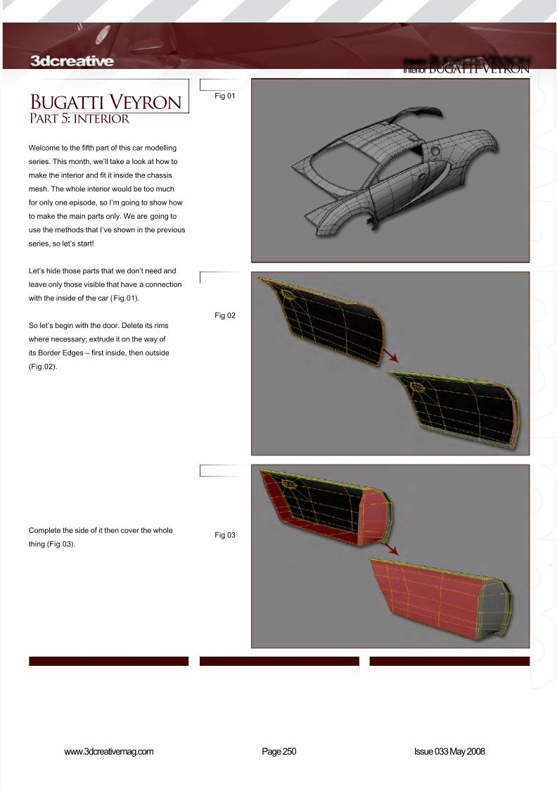
8/10/2019 3DCreative Magazine Issue 033 May 2008
http://slidepdf.com/reader/full/3dcreative-magazine-issue-033-may-2008 217/224
Page 250www.3dcreativemag.com Issue 033 May 2008
InteriorBugatti Veyron
Bugatti VeyronPart 5: interior
Welcome to the fth part of this car modelling
series. This month, we’ll take a look at how to
make the interior and t it inside the chassis
mesh. The whole interior would be too much
for only one episode, so I’m going to show how
to make the main parts only. We are going to
use the methods that I’ve shown in the previous
series, so let’s start!
Let’s hide those parts that we don’t need and
leave only those visible that have a connection
with the inside of the car (Fig.01).
So let’s begin with the door. Delete its rims
where necessary; extrude it on the way of
its Border Edges – rst inside, then outside
(Fig.02).
Complete the side of it then cover the whole
thing (Fig.03).
Fig 01
Fig 02
Fig 03

8/10/2019 3DCreative Magazine Issue 033 May 2008
http://slidepdf.com/reader/full/3dcreative-magazine-issue-033-may-2008 218/224
Page 251www.3dcreativemag.com Issue 033 May 2008
Bugatti Veyron Interior
Fig 04
Fig 05
Fig 06
Use the same method for the surface at the
meeting of the wheel arch and the door (Fig.04).
Pay attention to the sides; we should remember
that this is needed so that we can actually close
the door if it were a real life model.
As we did before, let’s make the surface under
the door (Fig.05). Extrude out the edges, as
shown in the picture.
Continue to extrude (Fig.06).
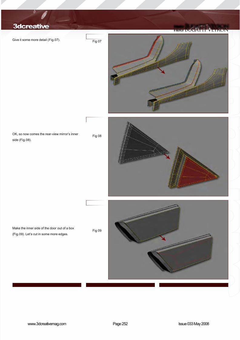
8/10/2019 3DCreative Magazine Issue 033 May 2008
http://slidepdf.com/reader/full/3dcreative-magazine-issue-033-may-2008 219/224
Page 252www.3dcreativemag.com Issue 033 May 2008
InteriorBugatti Veyron
Give it some more detail (Fig.07).
OK, so now comes the rear-view mirror’s inner
side (Fig.08).
Make the inner side of the door out of a box
(Fig.09). Let’s cut in some more edges.
Fig 07
Fig 08
Fig 09
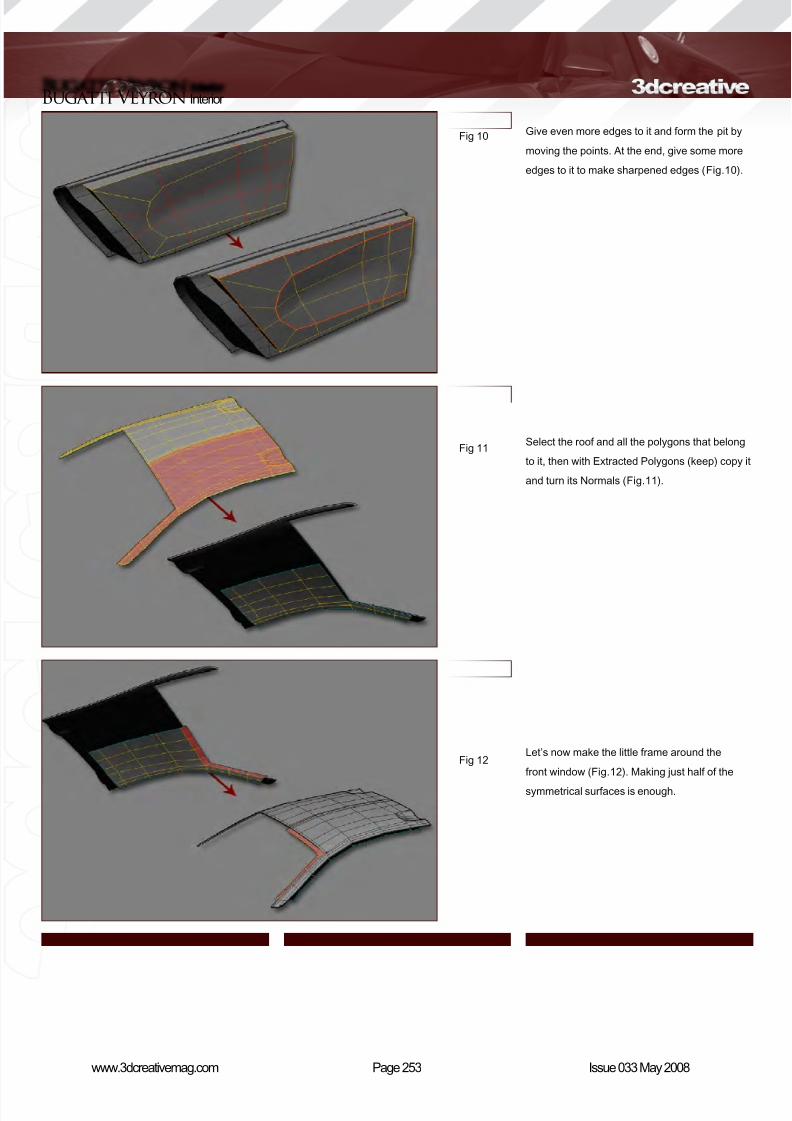
8/10/2019 3DCreative Magazine Issue 033 May 2008
http://slidepdf.com/reader/full/3dcreative-magazine-issue-033-may-2008 220/224
Page 253www.3dcreativemag.com Issue 033 May 2008
Bugatti Veyron Interior
Give even more edges to it and form the pit by
moving the points. At the end, give some more
edges to it to make sharpened edges (Fig.10).
Select the roof and all the polygons that belong
to it, then with Extracted Polygons (keep) copy it
and turn its Normals (Fig.11).
Let’s now make the little frame around the
front window (Fig.12). Making just half of the
symmetrical surfaces is enough.
Fig 10
Fig 11
Fig 12

8/10/2019 3DCreative Magazine Issue 033 May 2008
http://slidepdf.com/reader/full/3dcreative-magazine-issue-033-may-2008 221/224
Page 254www.3dcreativemag.com Issue 033 May 2008
InteriorBugatti Veyron
Complete the continuation of the rim (Fig.13).
Form the back window using Extrude again
(Fig.14).
Let’s now make the little frame around the rear
window (Fig.15).
Fig 13
Fig 14
Fig 15
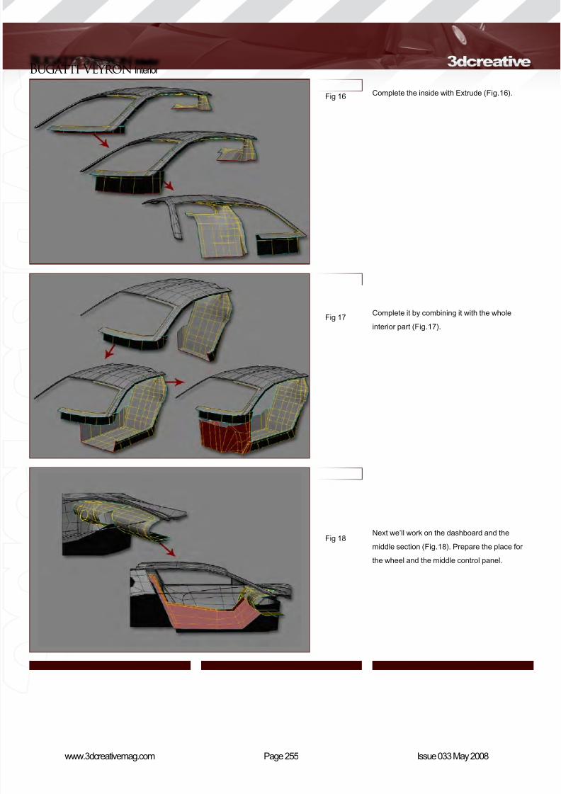
8/10/2019 3DCreative Magazine Issue 033 May 2008
http://slidepdf.com/reader/full/3dcreative-magazine-issue-033-may-2008 222/224
Page 255www.3dcreativemag.com Issue 033 May 2008
Bugatti Veyron Interior
Complete the inside with Extrude (Fig.16).
Complete it by combining it with the whole
interior part (Fig.17).
Next we’ll work on the dashboard and the
middle section (Fig.18). Prepare the place for
the wheel and the middle control panel.
Fig 16
Fig 17
Fig 18
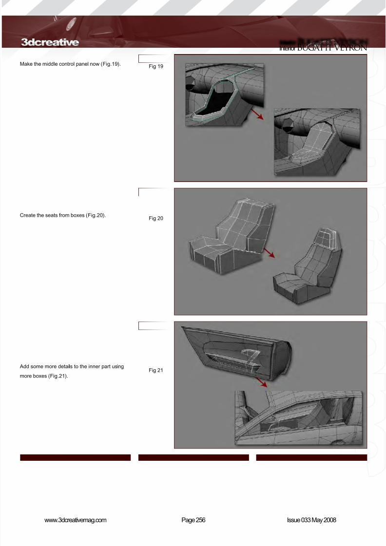
8/10/2019 3DCreative Magazine Issue 033 May 2008
http://slidepdf.com/reader/full/3dcreative-magazine-issue-033-may-2008 223/224
Page 256www.3dcreativemag.com Issue 033 May 2008
InteriorBugatti Veyron
Make the middle control panel now (Fig.19).
Create the seats from boxes (Fig.20).
Add some more details to the inner part using
more boxes (Fig.21).
Fig 19
Fig 20
Fig 21
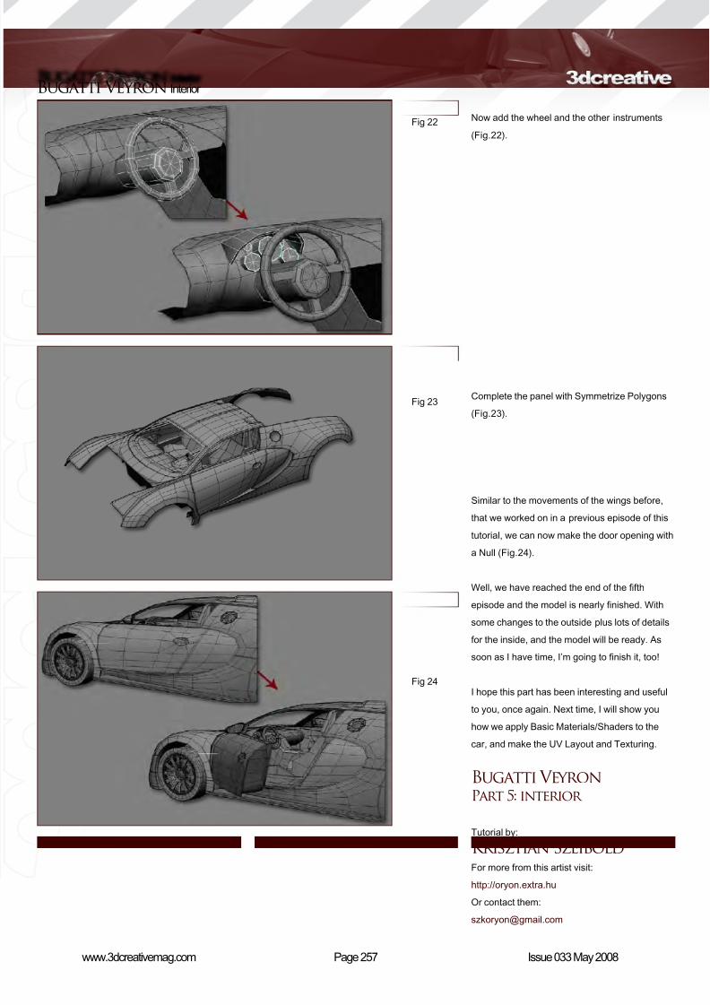
8/10/2019 3DCreative Magazine Issue 033 May 2008
http://slidepdf.com/reader/full/3dcreative-magazine-issue-033-may-2008 224/224
Bugatti Veyron Interior
Now add the wheel and the other instruments
(Fig.22).
Fig 22


![Grid Magazine December 2011 [#033]](https://img.dokumen.tips/doc/110x75/568befa01a28ab89338cd1bb/grid-magazine-december-2011-033.jpg)