Embed Size (px)
Citation preview

Instructions-Parts
XPXPXP PressurePressurePressure MonitorMonitorMonitor KitKitKit 3A1331JEN
MonitorsMonitorsMonitors pressurespressurespressures tototo provideprovideprovide ratioratioratio assuranceassuranceassurance ononon XPXPXP andandand XPXPXP---hfhfhf pluralpluralplural---componentcomponentcomponent sprayers.sprayers.sprayers. ForForForprofessionalprofessionalprofessional useuseuse only.only.only. NotNotNot approvedapprovedapproved forforfor useuseuse ininin explosiveexplosiveexplosive atmosphereatmosphereatmosphere locations.locations.locations.
ImportantImportantImportant SafetySafetySafety InstructionsInstructionsInstructionsRead all warnings and instructions in this manual and the XP orXP-hf operation manual. Save these instructions.
See page 2 for Kit numbers anddescriptions.
PROVEN QUALITY. LEADING TECHNOLOGY.

ContentsContentsContentsKit Numbers ....................................................... 2Overview............................................................ 3
Operating Window ....................................... 3Component Identification..................................... 4
Line Power Kits............................................ 4Air Turbine Kits ............................................ 5User Interface .............................................. 6
Installation.......................................................... 8Location ...................................................... 8Install Air Solenoid (XP Sprayers) ................. 8Install Air Solenoid (XP-hf
Proportioners) ................................ 9Install Electronics Box and LCM.................... 10Install Pressure Transducers ........................ 10Route Air Hoses and Cables......................... 10
Startup............................................................... 11Shutdown........................................................... 11Advisories and Alarms ........................................ 11
Clear Alarms................................................ 11View Current Alarms .................................... 11
View Error Log............................................. 11Error Codes................................................. 12
Repair................................................................ 15Replace LCM Tear Off Sheet ........................ 15Replace Switch Fuses.................................. 15Replace Filter Element ................................. 15Replace Alternator or Turbine
Cartridge........................................ 16Notes................................................................. 17Parts.................................................................. 18Appendix A— User Interface Display ................... 22
Setup Mode Details...................................... 22Run Mode Details ........................................ 25
Appendix B - Breakout ModuleConnections.......................................... 27
Accessories........................................................ 27Technical Data ................................................... 28Notes................................................................. 29
KitKitKit NumbersNumbersNumbersKitsKitsKits forforfor XPXPXP SprayerSprayerSprayer
262940 Line Power Pressure Monitor Kit
262942 Air Turbine Power Pressure Monitor Kit
KitsKitsKits forforfor XPXPXP---hfhfhf ProportionerProportionerProportioner
26C008 Line Power Pressure Monitor Kit
26C009 Air Turbine Power Pressure Monitor Kit
2 3A1331J
Overview
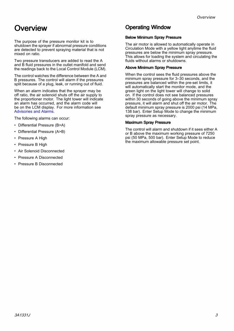
OverviewOverviewOverviewThe purpose of the pressure monitor kit is toshutdown the sprayer if abnormal pressure conditionsare detected to prevent spraying material that is notmixed on ratio.
Two pressure transducers are added to read the Aand B fluid pressures in the outlet manifold and sendthe readings back to the Local Control Module (LCM).
The control watches the difference between the A andB pressures. The control will alarm if the pressuressplit because of a plug, leak, or running out of fluid.
When an alarm indicates that the sprayer may beoff ratio, the air solenoid shuts off the air supply tothe proportioner motor. The light tower will indicatean alarm has occurred, and the alarm code willbe on the LCM display. For more information seeAdvisories and Alarms.
The following alarms can occur:
• Differential Pressure (B>A)• Differential Pressure (A>B)• Pressure A High• Pressure B High• Air Solenoid Disconnected• Pressure A Disconnected• Pressure B Disconnected
OperatingOperatingOperating WindowWindowWindow
BelowBelowBelow MinimumMinimumMinimum SpraySpraySpray PressurePressurePressure
The air motor is allowed to automatically operate inCirculation Mode with a yellow light anytime the fluidpressures are below the minimum spray pressure.This allows for loading the system and circulating thefluids without alarms or shutdowns.
AboveAboveAbove MinimumMinimumMinimum SpraySpraySpray PressurePressurePressure
When the control sees the fluid pressures above theminimum spray pressure for 3–30 seconds, and thepressures are balanced within the pre-set limits, itwill automatically start the monitor mode, and thegreen light on the light tower will change to solidon. If the control does not see balanced pressureswithin 30 seconds of going above the minimum spraypressure, it will alarm and shut off the air motor. Thedefault minimum spray pressure is 2000 psi (14 MPa,138 bar). Enter Setup Mode to change the minimumspray pressure as necessary.
MaximumMaximumMaximum SpraySpraySpray PressurePressurePressure
The control will alarm and shutdown if it sees either Aor B above the maximum working pressure of 7250psi (50 MPa, 500 bar). Enter Setup Mode to reducethe maximum allowable pressure set point.
3A1331J 3

Component Identification
ComponentComponentComponent IdentificationIdentificationIdentification
LineLineLine PowerPowerPower KitsKitsKits
SA
SD
SG
SB
SE
SFSC
E
DA
SJ
SH
C
B
F
SL
SL
SA
SD
SG
26C008 262940
E
Figure 1
TableTableTable 111 CableCableCable IdentificationIdentificationIdentification TableTableTable
Ref.Ref.Ref. CableCableCable IdentificationIdentificationIdentification LabelLabelLabel
A Power Supply CAN
B A PressureTransducer
6–Blue
C B PressureTransducer
7–Red
D LCM Cable 1–Blue
E Solenoid Cable 3–Red
F Light Tower Cable 4–Green
TableTableTable 222 SystemSystemSystem ComponentComponentComponent IdentificationIdentificationIdentification TableTableTable
Ref.Ref.Ref. SystemSystemSystem ComponentComponentComponent
SA XP Motor Air Controls (reference)
SB Local Control Module (LCM)
SC Power Entry Fuses and Switch
SD Motor Air Solenoid Valve, 24 Volt
SE Power Supply, 24 Volt
SF Light Tower, 24 Volt
SG XP Air Inlet Assembly (reference)
SH Breakout Module
SJ XP Fluid Manifold (reference)
SL Motor Air Hose
4 3A1331J

Component Identification
AirAirAir TurbineTurbineTurbine KitsKitsKits
H
G
SN
AG
SM
SK
SL
SA
SD
SG
26C009 262942
E
SA
SD
SG
SB
SF
E
D
SJ
SH
C
B
F
SL
Figure 2
TableTableTable 333 CableCableCable IdentificationIdentificationIdentification TableTableTable
Ref.Ref.Ref. CableCableCable IdentificationIdentificationIdentification LabelLabelLabel
A Power Supply CAN
B A PressureTransducer
6–Blue
C B PressureTransducer
7–Red
D LCM Cable 1–Blue
E Solenoid Cable 3–Red
F Light Tower 4–Green
G Air Tubing —
H Air Exhaust —
TableTableTable 444 SystemSystemSystem ComponentComponentComponent IdentificationIdentificationIdentification TableTableTable
Ref.Ref.Ref. SystemSystemSystem ComponentComponentComponent
SA XP Motor Air Controls (reference)
SB Local Control Module (LCM)
SD Motor Air Solenoid Valve, 12 Volt
SF Light Tower, 12 Volt
SG XP Air Inlet Assembly (reference)
SH Breakout Module
SJ XP Fluid Manifold (reference)
SK Turbine Air Regulator
SL Motor Air Hose
SM Air Powered Alternator, 12 Volt
SN Alternator Power Shutoff Valve
3A1331J 5

Component Identification
UserUserUser InterfaceInterfaceInterface
Figure 3
TableTableTable 555 LCMLCMLCM ButtonButtonButton FunctionsFunctionsFunctions
ButtonButtonButton FunctionFunctionFunction
Mode Select between Run and SetupModes.
Spray Start and stop the air motor. Themotor will stay on indefinitely ifpressures are below minimumspray pressure. Monitor modewill start within 30 seconds if thepressures are above the minimumspray pressure and no errorsexist. All errors are ignored for 30seconds. Default is 2000 psi (138MPa, 138 bar)
ArrowsUp/Down
Navigate up or down within ascreen or to a new screen.
Soft keys activate the mode oraction represented by the icon nextto each soft key.
See Table 2 for soft key icons andactions.
Top Soft Key: Edit data, acceptedited data, or move right within anumber field.
Soft Keys
Bottom Soft Key: Enter a screen,exit a screen, or cancel edited data.
NOTICENOTICENOTICETo prevent damage to soft key buttons, do notpress the buttons with sharp objects such as pens,plastic cards, or fingernails.
TableTableTable 666 DisplayDisplayDisplay SoftSoftSoft KeyKeyKey IconsIconsIcons
IconIconIcon FunctionFunctionFunction
Enter Screen In screens that have editable fields,press to access the fields andmake changes.
Exit Screen In screens that have editable fields,press to exit edit mode.
Enter In screens that have editable fields,press to make data selections orto enter changes.
Right In screens that have editable fields,press to move to the right while ina field.
Cancel Cancel a selection or edited data.Returns to the original data.
Clear ErrorLog
Clear entire error log..
6 3A1331J

Component Identification
DisplayDisplayDisplay ComponentsComponentsComponents
The following tables identify components shown onthe spray mode active, circulation mode active, alarmactive, and deviation active run screens. For moreinformation see Run Mode Details, page 25.
Spray Mode Active ScreenFigure 4
Circulation Mode Active ScreenFigure 5
Alarm Active ScreenFigure 6
Deviation Active ScreenFigure 7
TableTableTable 777 DisplayDisplayDisplay ComponentsComponentsComponents
IconIconIcon FunctionFunctionFunction
Actual spray pressures
Differential pressure alarmbar graph
Selected pressure units.Indicates that you are inspray mode.
Indicates that you are incirculation mode.
Indicates that there is anactive alarm.
Indicates that there is anactive deviation.
3A1331J 7
Installation
InstallationInstallationInstallation
Shutdown the XP Sprayer before installing yourpressure monitor kit. Follow the ShutdownShutdownShutdown andPressurePressurePressure ReliefReliefRelief ProcedureProcedureProcedure in the XP Sprayeroperation manual. All electrical wiring must bedone by a qualified electrician and comply with alllocal codes and regulations.
The procedures in this section are specific to eachcomponent of the pressure monitor kit. For sprayerinstallation instructions, refer to the XP70 SprayerOperation manual or the XP-hf Operation manual. .
LocationLocationLocation
These pressure monitoring kits are not approvedfor use in hazardous atmosphere locations.
Installing this kit on an XP Sprayer or an XP-hfProportioner that is EX approved, voids theapproval. The EX mark should be removed fromthe machine ID plate when this kit is installed.
NOTICENOTICENOTICEDo not store a XP Sprayer with a pressure monitorkit outside in the rain. Use protective bag 16J717to prevent damage to the electronic components,used with the pressure monitor kit, when storedoutside.
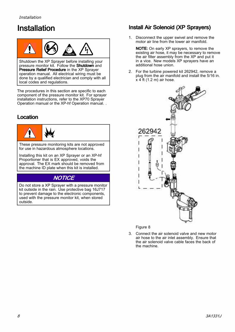
InstallInstallInstall AirAirAir SolenoidSolenoidSolenoid (XP(XP(XP Sprayers)Sprayers)Sprayers)
1. Disconnect the upper swivel and remove themotor air line from the lower air manifold.
NOTE:NOTE:NOTE: On early XP sprayers, to remove theexisting air hose, it may be necessary to removethe air filter assembly from the XP and put itin a vice. New models XP sprayers have anadditional hose union.
2. For the turbine powered kit 262942, remove aplug from the air manifold and install the 5/16 in.x 4 ft (1.2 m) air hose.
Figure 83. Connect the air solenoid valve and new motor
air hose to the air inlet assembly. Ensure thatthe air solenoid valve cable faces the back ofthe machine.
8 3A1331J

Installation
InstallInstallInstall AirAirAir SolenoidSolenoidSolenoid(XP(XP(XP---hfhfhf Proportioners)Proportioners)Proportioners)
1. Loosen filter bracket screws (SC).2. Disconnect air tubing (H) between the filter and
regulator assemblies.3. Remove the air line and replace with the air hose
provided in the pressure monitor kit along withthe nipple fitting and swivels.
4. Connect the solenoid assembly to pipe swivels.
NOTE:NOTE:NOTE: Ensure that the solenoid electricalconnector is toward the back and facing down.
5. Adjust the filter assembly position and re-tightenthe screws.
6. For the air turbine power kit, remove cap (C) andinstall air hose (42) for air supply.
7. Connect solenoid cable (77) to the solenoid.
SeriesSeriesSeries AAA andandand BBB
SeriesSeriesSeries CCC
3A1331J 9

Installation
InstallInstallInstall ElectronicsElectronicsElectronics BoxBoxBox andandand LCMLCMLCM
1. Use three screws (61) and three nuts (62) tomount the box bracket to the cart (as shown inthe figure below). For XP systems with an XL airmotor, mount the box bracket on the oppositeside of the cart.
NOTE:NOTE:NOTE: Nuts are not used on newer carts withnuts crimped onto the cart plate.
2. For line power kits, install the appropriatepower supply cord(s). US, European, andAustralia/Asia cord adapters are supplied. SeeTechnical Data, page 28.
XPXPXP CartCartCart InstallationInstallationInstallation ––– SeriesSeriesSeries AAA andandand BBB
XPXPXP CartCartCart InstallationInstallationInstallation ––– SeriesSeriesSeries CCCFigure 9
InstallInstallInstall PressurePressurePressure TransducersTransducersTransducers
1. Remove plugs from the circulation fluid manifold.
NOTE:NOTE:NOTE: Keep the plugs to reuse if you everremove the pressure monitor kit.
2. Connect pressure transducer (4), with blue#6 label, with black o-ring (13) to the A sideof the circulation manifold. Connect pressuretransducer (4), with red #7 label, with black o-ring(13) to the B side of the circulation manifold.Tighten to 40–50 ft-lb (54–67 N•m) beforeapplying fluid pressure.
Pressure TransducersFigure 10
RouteRouteRoute AirAirAir HosesHosesHoses andandand CablesCablesCables
Secure air hose and cable connections.
Use tie wraps provided to secure hose and cables.For air turbine kits, route exhaust hose (41) downcart leg and secure.
AirAirAir TurbineTurbineTurbine Kits:Kits:Kits:
Secure solenoid cable (F) to air hoses with tie wrap.Route exhaust hose (J) down the inside of the cartleg and secure with tie wrap.
LineLineLine PowerPowerPower Kits:Kits:Kits:
Route solenoid cable (F) behind the air hose andsecure with tie wrap.
10 3A1331J

Startup
StartupStartupStartup1. Refer to the XP Sprayer or XP-hf Proportioner
Operation manual for sprayer startup instructions.
NOTE:NOTE:NOTE: The pressure monitor kit does not changethe operation procedures in the XP Sprayer orXP-hf Proportioner Operation manual.
2. Turn on power.
a. For Line Power Kits: Turn on power switch(9) located on the electronics box.
b. For Air Turbine Kits: Open ball valve (22)located outside of the electronics box.
NOTE:NOTE:NOTE: The air pressure regulator should beset at 22 +/- 5 psi (.15 +/- .03 MPA, 1.5 +/-3 MPa).
3. Wait for the power up screen to complete. TheCirculation Mode screen will display. The lighttower will briefly flash green, yellow, and red toverify the lights before staying on yellow. Wait forthe run screen to appear.
4. Set system parameters before spraying.These can be changed as necessary.
Press to enter Setup Mode. Formore information and default settings, seeAppendix A— User Interface Display, page 22.
5. In Circulation Mode, all alarms are disabledexcept for the air solenoid detection, pressuresensor failure, and high pressure alarms.
NOTE:NOTE:NOTE: In Manual Bypass Mode you can stillspray when one pressure transducer fails, butthe control no longer monitors the pressures andwill not shut off the sprayer. This is for temporaryuse only to complete the job.
a. To enter Manual Bypass Mode, set theminimum spray pressure equal to themaximum spray pressure on setup screen2. In Manual Bypass Mode, the system cannever get into Spray Mode. The event codeEVC1 is displayed on the information screenand logged in the error log. The yellow lightis always on and all alarms are ignored.
b. To exit Manual Bypass Mode, set theminimum spray pressure and maximumspray pressure to different spray pressures.Event code EVC0 will log in the error logwhen Bypass Mode is disabled.
6. Press to start the air motor. The red LEDwill turn on and the motor will start. Only spraywhen the green light on the light tower is on. Formore information about the LCM run screens,see Run Mode Details, page 25.
ShutdownShutdownShutdown
1. Press . The red LED will turn off and themotor will stop.
2. Turn off the power switch or ball valve on theoutside of the electronics box.
AdvisoriesAdvisoriesAdvisories andandand AlarmsAlarmsAlarms
ClearClearClear AlarmsAlarmsAlarms
Fore more information about the alarms, seeInformation Screen, page 26.
To clear an error:
1. Press to clear the alarm.
2. Press to restart the air motor.
ViewViewView CurrentCurrentCurrent AlarmsAlarmsAlarms
From the Run screen, press to navigateto the Information screen. The Information screendisplays current alarms or advisories.
Figure 11
ViewViewView ErrorErrorError LogLogLog
Setup Screen 3 is the error log screen. It displays themost recent error on the top of the list with the pastthree errors below it. This screen displays a list ofadvisory or alarm error codes and the time the erroroccurred since the kit was powered on.
3A1331J 11

Advisories and Alarms
ErrorErrorError CodesCodesCodes
CodeCodeCode IconIconIcon CodeCodeCode NameNameName LightLightLight TowerTowerTowerCodeCodeCode
CauseCauseCause SolutionSolutionSolution
AlarmsAlarmsAlarms
Ran out of B sidematerial.
Refill hopper or changedrum.
Cavitating B side pump. Warm material or addfeed pressure.
B material leaking. Follow pumptroubleshooting in XP70Sprayer manual.
No mix manifold B siderestriction.
Add restriction to Bside on mix manifold tobalance pressures.
A side hose is too small. Change to larger hosesize.
J4AXJ4AXJ4AX Differential Pressure(A>B)
Red Solid
Improper configuration. Adjust setpoints onsetup screens. SeeSetup Mode Details,page 22.
Ran out of A sidematerial.
Refill hopper or changedrum.
Cavitating A side pump. Warm material or addfeed pressure.
A material leaking. Follow pumptroubleshooting in XP70Sprayer manual.
Too much restrictionon mix manifold B siderestriction.
Reduce restriction to Bside on mix manifold.
* Bside hose is too small. Change to largerdiameter hose size.
* No B side offset incontrol setup.
Adjust B side offset insetup screens if B nor-mally runs at a higherpressure than A. SeeSetup Mode Details,page 22.
J4BXJ4BXJ4BX Differential Pressure(B>A)
Red Solid
Improper configuration. Adjust setpoints onsetup screens. SeeSetup Mode Details,page 22.
Broken cable. Replace transducer.P6AXP6AXP6AX Pressure ADisconnected
Red Solid
Disconnected cable. Connect cable.
Broken cable. Replace transducer.P6BXP6BXP6BX Pressure BDisconnected
Red Solid
Disconnected cable. Connect cable.
Broken cable. Replace cable.
Disconnected cable. Connect cable.
WJPXWJPXWJPX Air SolenoidDisconnected
Red Solid
Damaged solenoid. Replace solenoid.
P4AXP4AXP4AX Pressure A High Red Solid A pressure exceededmaximum workingpressure set point.
Reduce air pressure tomotor or adjust setpoint.
12 3A1331J

Advisories and Alarms
CodeCodeCode IconIconIcon CodeCodeCode NameNameName LightLightLight TowerTowerTowerCodeCodeCode
CauseCauseCause SolutionSolutionSolution
AlarmsAlarmsAlarms
Reduce air pressure tomotor or adjust setpoint.
A pressure exceededmaximum workingpressure set point.
Open down streamvalve.
Reduce downstreamrestriction.
P4BXP4BXP4BX Pressure B High Red Solid
Blockage in B linedownstream.
Clean mix manifold.
* Remote mix manifold applications only.
3A1331J 13

Advisories and Alarms
CodeCodeCode IconIconIcon CodeCodeCode NameNameName LightLightLight TowerTowerTowerCodeCodeCode
CauseCauseCause SolutionSolutionSolution
DeviationsDeviationsDeviations
Ran out of B sidematerial.
Refill hopper or changedrum.
Cavitating B side pump. Warm material or addfeed pressure.
B material leaking. Follow pumptroubleshooting in XP70Sprayer manual.
No mix manifold B siderestriction.
Add restriction to Bside on mix manifold tobalance pressures.
J3AXJ3AXJ3AX Differential Pressure(A>B)
YellowFlashing
A side hose is too small. Change to larger hosesize.
Ran out of A sidematerial.
Refill hopper or changedrum.
Cavitating A side pump. Warm material or addfeed pressure.
A material leaking. Follow pumptroubleshooting in XP70Sprayer manual.
Too much restrictionon mix manifold B siderestriction.
Reduce restriction to GBside on mix manifold.
* B side hose too small. Change to larger hosesize.
J3BXJ3BXJ3BX Differential Pressure(B>A)
YellowFlashing
* No B side offset incontrol setup.
Add B side offset insetup screen.
EventsEventsEvents andandand AdvisoriesAdvisoriesAdvisories
EERXEERXEERX Under Minimum SprayPressure, Circulation,
Loading
Yellow Under minimum spraypressure.
Normal for circulationmode.
EVC0EVC0EVC0 Manual Bypass ModeEnabled and Logged.Minimum Pressure =Maximum Pressure
YellowManual Bypass Mode
Reset minimum spraypressure and maximum
spray pressure inSetup Mode.
EVC1EVC1EVC1 — Manual Bypass ModeDisabled and Logged
—Event log only —
ELCXELCXELCX — Control Power UpTimer set to zero in Log
—Event log only —
* Remote mix manifold applications only.
14 3A1331J

Repair
RepairRepairRepairFor system specific repair procedures, refer to yoursystem Instructions-Parts manual.
ReplaceReplaceReplace LCMLCMLCM TearTearTear OffOffOff SheetSheetSheet
The LCM is supplied with 10 protective tear off sheetsthat prevent spray material from covering the LCMdisplay.
1. Peel away the dirty protective sheet.2. Install a new protective sheet (68) on the LCM
display.
Figure 12
ReplaceReplaceReplace SwitchSwitchSwitch FusesFusesFuses
ForForFor 262940262940262940 only.only.only.
1. Remove power inlet cord (55 or 57).2. Pry off small plastic cover above cord inlet.3. Pull fuses (63) out of power switch. Replace and
reassemble.
Figure 13
ReplaceReplaceReplace FilterFilterFilter ElementElementElement
There is a 5 micron air filter used with the regulatoron the Air Turbine Power Kit. Check the filter monthlyand replace element as needed.
1. Close main air shutoff valve on air supply lineand on unit. Depressurize air line.
2. Remove box cover (30).3. Press silver tab in, twist bowl to the left, and pull
down off of the regulator.4. Remove and replace element.5. Screw filter bowl on securely until the tab clicks.
Figure 14
3A1331J 15

Repair
ReplaceReplaceReplace AlternatorAlternatorAlternator ororor TurbineTurbineTurbineCartridgeCartridgeCartridge
ForForFor AirAirAir TurbineTurbineTurbine PowerPowerPower KitsKitsKits only.only.only.
Turbine alternator cartridge (34e) can be replaced inalternator (34).
34d
34a
34e
AB
Z
1. Turn off air supply.2. Close ball valve (22). See Parts, page 18.3. Remove box cover (30).4. Disconnect the alternator power supply cable (A)
from the LCM (21). Disconnect ground wire (Z).
AZ
5. Disconnect air tube (40) from the alternator (34).
6. Remove two screws (15) to remove alternatorfrom the box (1).
7. Remove four screws (34d) to separate alternatorhousings.
8. Disconnect turbine cartridge (34e) ribbonconnector from board (AB).
9. Replace gasket (34a) if damaged. Place betweenhousings before securing with screws (34d).
10. Reassemble.
Note
• Lightly lubricate turbine o-ring beforeinstalling turbine in housing.
• Align ribbon connector and firmly pressthe cartridge into the top housing.
• Connect turbine 3–pin connector onmain circuit board.
• Torque housing screws evenly to 18in-lb (2 N•m).
• Reassemble into control box (1).11. Verify turbine air pressure is set to 22 +/- 5 psi
(.15 +/- .03 MPa, 1.5 +/- .3 bar).
NOTICENOTICENOTICETo avoid damage to the alternator, do not set theregulator air pressure higher than 27 psi (.19 MPa,1.9 bar).
16 3A1331J

Notes
NotesNotesNotes
3A1331J 17

Parts
PartsPartsParts
262940262940262940 LineLineLine PowerPowerPower PressurePressurePressure MonitorMonitorMonitor KitKitKit26C00826C00826C008 LineLineLine PowerPowerPower PressurePressurePressure MonitorMonitorMonitor KitKitKit
Apply sealant to all non-swiveling pipe threads.
18 3A1331J

Parts
Ref.Ref.Ref. PartPartPart DescriptionDescriptionDescription Qty.Qty.Qty.
1 26C342 BOX, weldment assembly 12 26C340 BRACKET, top mount 13 15M293 POWERSUPPLY, 24VDC,
2.5A, 60W, gnd wire1
4 15M669 SENSOR, pressure, fluidoutlet
2
5 15X472 LIGHT TOWER, m12 16 — BRACKET, mounting,
assembly1
7 258999 MODULE, LCM, breakout 18 157785 SWIVEL 29 121254 SWITCH, power, 120V 111 102410 SCREW, cap, sch 412 100016 WASHER, lock 113 121399 O-RING 012, solvent
resistant2
14▲ 189930 LABEL, caution 115 104371 SCREW,cap sch 10 x
0.3759
16 104472 SCREW, cap; 10–32 x 1.5 417 110755 WASHER, plain 118 — SCREW, countersunk,
6-32 x 0.382
20■ 110047 HOSE, coupled, 18 in.(457.2 mm)
1
20◊ 278770 HOSE, 13 in. x 1 in.25 121253 KNOB, display adjustment 121+ 24H286 MODULE, LCM; includes
21a and instructions1
21a 16G728 TOKEN, PM software; notshown
1
21b — MODULE, LCM 125 121253 KNOB, display adjustment 126 119992 NIPPLE, 3/4 x 3/4 npt 127 111530 MUFFLER 128a■ 16G901 VALVE, 24VDC, internal
pilot, 3/41
28b◊ 17S716 VALVE, 3–way, n.c.,24VDC
1
29 15T859 CABLE, assembly, DB25,10 ft (3 m)
1
30 24H298 COVER, box 1
Ref.Ref.Ref. PartPartPart DescriptionDescriptionDescription Qty.Qty.Qty.
31 102063 WASHER, lock, ext 132 108865 SCREW, cap, button hd 147 16H323 GROMMET, one slit 153 120206 MUFFLER, sintered, dia
1/81
55 116281 CORD SET, IEC320(M-F),6 ft (1.8 m)
1
56 195551 RETAINER, plug, adapter 157 245202 CORD, SET, USA, 10 ft (3
m), 13 AMP, 120V1
58 242001 CORD SET, adapter,Europe; 8 in. (20 mm)
1
59 242005 CORD SET, adapter,Australia-Asia; 8 in. (20mm)
1
61 113796 SCREW, flanged, hex hd 362 115942 NUT, hex, flange head 363 121261 FUSE, 250V / 1.2A 265 114606 PLUG, hole 167 113783 SCREW, 1/4–20, pn hd 468 16H378 SHIELD, membrane, LCM
(pack of 10)1
69 114225 TRIM, edge protection; 0.6ft (0.18 m)
1
70 16J685 LABEL, error codes 171 16J722 LABEL, error codes (all
languages)1
74◊ 17S719 NIPPLE, long, 1 in. npt 175◊ 17S718 MUFFLER, 1 in. npt 176◊ 17G388 NIPPLE, 1 in. npt 177 131181 CABLE, GCA solenoid 178◊ 160022 FITTING, swivel, 1 in. 1
▲ Replacement Danger and Warning labels, tags,and cards are available at no cost.+ Replacement electronic components do nothave Pressure Monitor specific software installed.Therefore, use software upgrade token (21a) toinstall software before use.◊ Parts included in Kit 26C008.■ Parts included in Kit 262940.
3A1331J 19
Parts
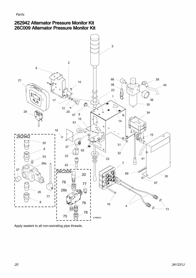
262942262942262942 AlternatorAlternatorAlternator PressurePressurePressure MonitorMonitorMonitor KitKitKit26C00926C00926C009 AlternatorAlternatorAlternator PressurePressurePressure MonitorMonitorMonitor KitKitKit
Apply sealant to all non-swiveling pipe threads.
20 3A1331J

Parts
Ref.Ref.Ref. PartPartPart DescriptionDescriptionDescription Qty.Qty.Qty.1 26C342 BOX, assembly 12 26C340 BRACKET, top mount 14 15M669 SENSOR, pressure, fluid
outlet2
5 16H600 LIGHT, tower, M12, 12VDC 16 — BRACKET, mounting,
assembly1
7 258999 MODULE, LCM, breakout 18 157785 FITTING, swivel; 3/4 mxf 212 100016 WASHER, lock; 1/4 113 121399 O-RING 012, solvent
resistant2
14▲ 189930 LABEL, caution 115 104371 SCREW, cap sch 10 x 0.375 916 104472 SCREW, cap; 10–32 x 1.5 417 110755 WASHER, plain 118 — SCREW, cap, hex, button
hd; 6–32 x 3/82
20■ 110047 HOSE, coupled, 3/4 npt x18 in. (457.2 mm)
1
20◊ 278770 HOSE, 13 in. x 1 in. hose21+ 24H286 MODULE, LCM; includes
21a and instructions1
21a 16G728 TOKEN, PM software; notshown
1
21b — MODULE, LCM 122 15B565 VALVE, ball 123 114314 WASHER, plain 225 121253 KNOB, display adjustment 126 119992 NIPPLE, 3/4 x 3/4 npt 127 111530 MUFFLER 128a■ 16H550 VALVE, 12VDC, internal
pilot, 3/41
28b◊ 17E519 VALVE, 3–way, n.c., 12VDC
1
29 15T859 CABLE, assembly, DB25,10 ft (3 m)
1
30 24H298 COVER, box 131 C38163 WASHER, lock, ext. tooth 132 103833 SCREW, machined, crbh 134 262579 MODULE, alternator, M12,
non-IS1
34a 193154 GASKET, alternator 1
Ref.Ref.Ref. PartPartPart DescriptionDescriptionDescription Qty.Qty.Qty.34e 257147 CARTRIDGE, alternator 135 119644 FILTER REGULATOR, 3/8
npt (auto drain)1
35a 15D909 ELEMENT, filter, 5 micron 136 113911 GAUGE, pressure, air 137 121858 ELBOW ,3/8 nptm x 1/4
nptm1
38 15W017 VALVE, safety, regulator 139 114153 ELBOW, male, swivel 140 054175 TUBE, nylon, rd; 1/4, 2 ft
(0.6 mm)1
41 C12508 TUBING, nylon, round; 3/8,4 ft (1.2 m)
1
42 248208 HOSE, coupled ,6 ft (1.8m), 1/4 npsm, 5/16
1
47 16H323 GROMMET, one slit 153 120206 MUFFLER, sintered, dia 1/8 161 113796 SCREW, flanged, hex hd;
1/4–203
62 115942 NUT, hex, flange head;1/4–20
3
66 158962 ELBOW, st pipe, rdcg 167 113783 SCREW, 1/4–20, pn hd 468 16H378 SHIELD, membrane, LCM
(pack of 10)1
69 114225 TRIM, edge protection; 0.6ft (0.18 m)
1
70 16J685 LABEL, error codes 171 16J722 LABEL, error codes (all
languages)1
74◊ 17S719 NIPPLE, long, 1 in. npt 175◊ 17S718 MUFFLER, 1 in. npt 176◊ 17G388 NIPPLE, 1 in. npt 177 131181 CABLE, GCA solenoid 178◊ 26C009 FITTING, swivel, 1 in. 1
▲ Replacement Danger and Warning labels, tags,and cards are available at no cost.+ Replacement electronic components do nothave Pressure Monitor specific software installed.Therefore, use software upgrade token (21a) toinstall software before use.■ Parts included in Kit 262942.◊ Parts included in Kit 26C009.
3A1331J 21

Appendix A— User Interface Display
AppendixAppendixAppendix A—A—A— UserUserUser InterfaceInterfaceInterface DisplayDisplayDisplay
SetupSetupSetup ModeModeMode DetailsDetailsDetails
Setup mode screens enable user to view or modifysystem configuration data. User can set:
• Units of pressure• Differential pressure warning value• Differential pressure alarm value• High pressure limit value• Minimum spray pressure value• Normal B pressure offset value
SetupSetupSetup ScreenScreenScreen 111
Setup screen 1 enables users to set units ofmeasurement that will display on other screens,differential warning and differential alarm.Additionally, this screen displays the softwarenumber and version. Refer to the following table formore information.
IconIconIcon FunctionFunctionFunction
Warning Pressure
Adjust the differential pressuredeviation setpoint. The yellow lighton the light tower will be flashing.
Default: 400 psiRange: 0–2000 psiAlarm Pressure
Adjust the differential pressure alarmsetpoint. The red light on the lighttower will be solid on.
This is the main setting thatdetermines how far apart your A andB pressures can be before shuttingdown the machine. If the machineshuts down too easily, increase thisto a higher setpoint.
Default: 600 psiRange: 0–2000 psi
22 3A1331J

Appendix A— User Interface Display
SetupSetupSetup ScreenScreenScreen 222
Setup screen 2 enables users to set the high spraypressure alarm limit value, minimum spray pressurevalue and B pressure offset. Refer to the followingtable for more information.
IconIconIcon FunctionFunctionFunctionHigh Pressure Limit
Adjust the high pressure limit.
Default: 7250 psi (14 MPa, 138 bar)Range: 0-7250 psi (50 MPaA, 500bar) maximumMinimum Spray Pressure Limit
Adjust the lower spray pressure limit.
Default: 2000 psi (14 MPa, 138 bar)Range: 0-7250 psi (50 MPa, 500 bar)maximumPassword
The setup screens can be protectedby a password to restrict theiraccessibility. To set the password,see Set Password, page 24.
Range: 0-9999
IconIconIcon FunctionFunctionFunctionB Side Pressure Offset
Default: 0 psiRange: -999 to 999 psiOnly used for remote mix manifoldapplications where there is a normaldifference in pressure between A andB.
Remote mix manifold applicationsshould first be balanced with properhose sizing and adjusting the mixmanifold B restrictor. See the systemOperation manual.
Use if your differential alarm bargraph on the Spray screen is offto one side under normal sprayconditions.
See BBB SideSideSide PressurePressurePressure OffsetOffsetOffset ExampleExampleExample.
BBB SideSideSide PressurePressurePressure OffsetOffsetOffset ExampleExampleExample
In normal spray conditions, the B pressure is 300psi above the A pressure. The bar graph is offsetto one side.
Enter a B offset pressure of +300 psi. Now the bargraph Is centered.
The differential pressure alarm now sees nodifferential when the B pressure is 300 psi higherthan the A pressure. If the B pressure was normally300 psi lower than the A pressure, you would enter—300 psi to balance the offset.
3A1331J 23

Appendix A— User Interface Display
SetupSetupSetup ScreenScreenScreen 333
Setup screen 3 enables users to scroll through allerrors and clear the entire error log. The error log willdisplay the most recent error on the top of the list .Refer to the following table for more information.
IconIconIcon FunctionFunctionFunctionError Number
The first column lists the errornumber. Once the system hasmore than the maximum errorsallowed, then the oldest error will beover-written.
Maximum: 99Error Code
The second column lists the errorscodes. See Error Codes, page 12.
Maximum: 99Time
The third column shows the time thatthe error occurred since the unit waslast powered on. The time will alwaysstart at 0:00 when the system ispowered up. This time will be loggedas code ELCX.
Format: Hours : MinutesMaximum: 999 : 59Reset
Press the Reset icon to clear theentire error log.
SetSetSet PasswordPasswordPassword
Note
When the password is “0000,” the setupscreens can be accessed without enteringa password.
1. Navigate to setup screen 2.
2. Press to access fields to make changes.
3. Press to navigate to the password field.
Press to edit data.
4. Press and to increment ordecrement to the desired digits of the password.
5. Press to accept the password or press
to cancel.
6. Press to exit edit mode.
Note
The password screen is shown whenthe setup screens are accessed and thepassword function has been enabled bychanging the 0000 password.
Figure 15
If you set and forget the password, pleasecontact Graco Technical Assistance for a defaultpassword.
24 3A1331J

Appendix A— User Interface Display
RunRunRun ModeModeMode DetailsDetailsDetails
There are four Run Screens: Circulation ModeActive, Spray Mode Active, Alarm Active, andDeviation Active.
CirculationCirculationCirculation ModeModeMode ActiveActiveActive
This is the run screen that appears after the power upscreen. A and B pressure are shown. The bar acrossthe bottom indicates the magnitude of the differentialpressure with respect to the alarm setpoint. InCirculation Mode, all alarms are disabled except forthe Air Solenoid Detection High Pressure A, and HighPressure B alarms
If the user needs to spray with one of the aboveerrors active, set the Lower Spray Pressure Limitequal to the High Pressure Alarm Limit to enterManual Bypass Mode. Only use Manual BypassMode for emergency operation to finish the job. Thecontrol no longer monitors the pressures and will notshut off the sprayer.
IconIconIcon SystemSystemSystem StatusStatusStatus
Indicates that you are in CirculationMode and the fluid pressure is belowthe Lower Spray Pressure Limit.
All alarms are disabled except for AirSolenoid Detection, High PressureA, and High Pressure B alarms. Theyellow light on the light tower will besolid on.
This screen will also be used when inManual Bypass Mode.
Note
All alarms and deviationsare ignored in Bypass Mode.You will be allowed to spraybad material. The yellowlight will be solid on.
SpraySpraySpray ModeModeMode ActiveActiveActive
This is the run screen that appears during spraymode. A and B pressure are shown. The bar acrossthe bottom indicates the magnitude of the differentialpressure with respect to the alarm setpoint.
When the pressure first gets above the lower spraypressure limit, the user has 30 seconds to balancethe system differential pressure so it is less that thedifferential pressure deviation and alarm limits. Thenthe system will automatically go into Spray mode andstart monitoring all alarms and deviations.
IconIconIcon SystemSystemSystem StatusStatusStatus
Indicates that you are in spraymode, at least one of the pumps haspressure greater than the lower spraypressure limit, and the differentialpressure is less that the differentialpressure deviation setpoint.
The green light on the light tower willbe solid on.
3A1331J 25
Appendix A— User Interface Display
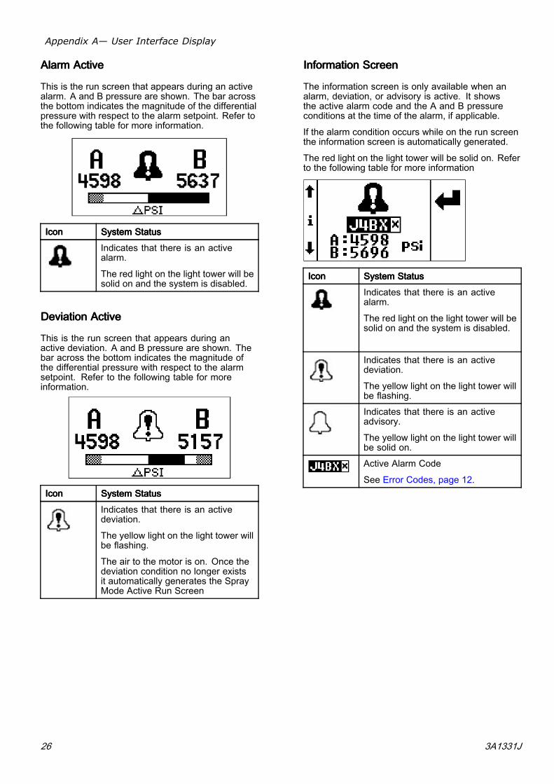
AlarmAlarmAlarm ActiveActiveActive
This is the run screen that appears during an activealarm. A and B pressure are shown. The bar acrossthe bottom indicates the magnitude of the differentialpressure with respect to the alarm setpoint. Refer tothe following table for more information.
IconIconIcon SystemSystemSystem StatusStatusStatus
Indicates that there is an activealarm.
The red light on the light tower will besolid on and the system is disabled.
DeviationDeviationDeviation ActiveActiveActive
This is the run screen that appears during anactive deviation. A and B pressure are shown. Thebar across the bottom indicates the magnitude ofthe differential pressure with respect to the alarmsetpoint. Refer to the following table for moreinformation.
IconIconIcon SystemSystemSystem StatusStatusStatus
Indicates that there is an activedeviation.
The yellow light on the light tower willbe flashing.
The air to the motor is on. Once thedeviation condition no longer existsit automatically generates the SprayMode Active Run Screen
InformationInformationInformation ScreenScreenScreen
The information screen is only available when analarm, deviation, or advisory is active. It showsthe active alarm code and the A and B pressureconditions at the time of the alarm, if applicable.
If the alarm condition occurs while on the run screenthe information screen is automatically generated.
The red light on the light tower will be solid on. Referto the following table for more information
IconIconIcon SystemSystemSystem StatusStatusStatus
Indicates that there is an activealarm.
The red light on the light tower will besolid on and the system is disabled.
Indicates that there is an activedeviation.
The yellow light on the light tower willbe flashing.
Indicates that there is an activeadvisory.
The yellow light on the light tower willbe solid on.
Active Alarm Code
See Error Codes, page 12.
26 3A1331J
Appendix B - Breakout Module Connections
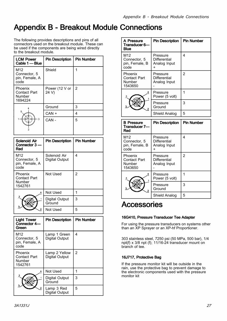
AppendixAppendixAppendix BBB --- BreakoutBreakoutBreakout ModuleModuleModule ConnectionsConnectionsConnectionsThe following provides descriptions and pins of allconnectors used on the breakout module. These canbe used if the components are being wired directlyto the breakout module.
LCMLCMLCM PowerPowerPowerCableCableCable 111———BlueBlueBlue
PinPinPin DescriptionDescriptionDescription PinPinPin NumberNumberNumber
M12Connector, 5pin, Female, Acode
Shield 1
PhoenixContact PartNumber1694224
Power (12 V or24 V)
2
Ground 3
CAN + 4
CAN - 5
SolenoidSolenoidSolenoid AirAirAirConnectorConnectorConnector 333 ———RedRedRed
PinPinPin DescriptionDescriptionDescription PinPinPin NumberNumberNumber
M12Connector, 5pin, Female, Acode
Solenoid AirDigital Output
4
PhoenixContact PartNumber1542761
Not Used 2
Not Used 1
Digital OutputGround
3
Not Used 5
LightLightLight TowerTowerTowerConnectorConnectorConnector 4—4—4—GreenGreenGreen
PinPinPin DescriptionDescriptionDescription PinPinPin NumberNumberNumber
M12Connector, 5pin, Female, Acode
Lamp 1 GreenDigital Output
4
PhoenixContact PartNumber1542761
Lamp 2 YellowDigital Output
2
Not Used 1
Digital OutputGround
3
Lamp 3 RedDigital Output
5
AAA PressurePressurePressureTransducerTransducerTransducer 6—6—6—BlueBlueBlue
PinPinPin DescriptionDescriptionDescription PinPinPin NumberNumberNumber
M12Connector, 5pin, Female, Bcode
PressureDifferentialAnalog Input+
4
PhoenixContact PartNumber1543650
PressureDifferentialAnalog Input-
2
PressurePower (5 volt)
1
PressureGround
3
Shield Analog 5
BBB PressurePressurePressureTransducerTransducerTransducer 7—7—7—RedRedRed
PinPinPin DescriptionDescriptionDescription PinPinPin NumberNumberNumber
M12Connector, 5pin, Female, Bcode
PressureDifferentialAnalog Input+
4
PhoenixContact PartNumber1543650
PressureDifferentialAnalog Input-
2
PressurePower (5 volt)
1
PressureGround
3
Shield Analog 5
AccessoriesAccessoriesAccessories16G410,16G410,16G410, PressurePressurePressure TransducerTransducerTransducer TeeTeeTee AdapterAdapterAdapter
For using the pressure transducers on systems otherthan an XP Sprayer or an XP-hf Proportioner.
303 stainless steel, 7250 psi (50 MPa, 500 bar), 1/4npt(f) x 3/8 npt (f); 11/16-24 transducer mount onbranch of tee.
16J717,16J717,16J717, ProtectiveProtectiveProtective BagBagBag
If the pressure monitor kit will be outside in therain, use the protective bag to prevent damage tothe electronic components used with the pressuremonitor kit
3A1331J 27
Technical Data
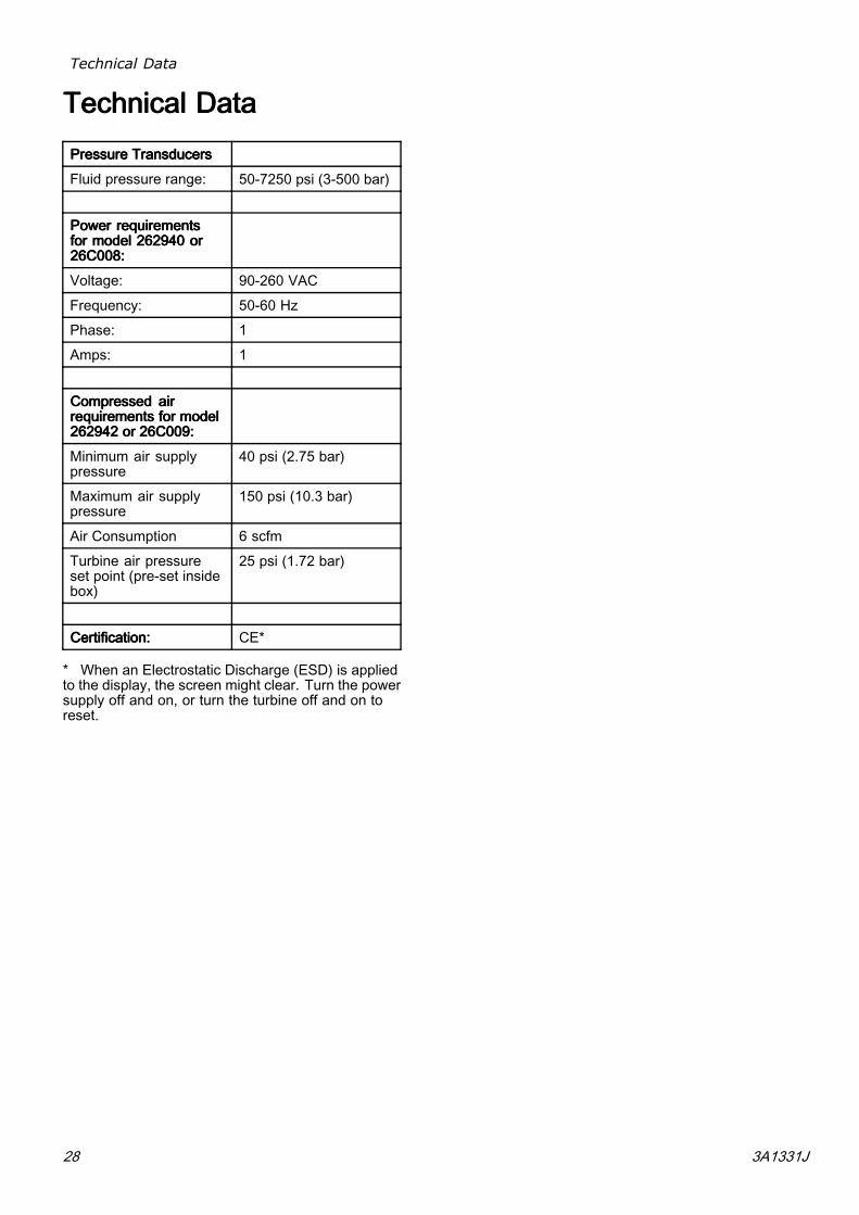
TechnicalTechnicalTechnical DataDataDataPressurePressurePressure TransducersTransducersTransducers
Fluid pressure range: 50-7250 psi (3-500 bar)
PowerPowerPower requirementsrequirementsrequirementsforforfor modelmodelmodel 262940262940262940 ororor26C008:26C008:26C008:
Voltage: 90-260 VAC
Frequency: 50-60 Hz
Phase: 1
Amps: 1
CompressedCompressedCompressed airairairrequirementsrequirementsrequirements forforfor modelmodelmodel262942262942262942 ororor 26C009:26C009:26C009:
Minimum air supplypressure
40 psi (2.75 bar)
Maximum air supplypressure
150 psi (10.3 bar)
Air Consumption 6 scfm
Turbine air pressureset point (pre-set insidebox)
25 psi (1.72 bar)
Certification:Certification:Certification: CE*
* When an Electrostatic Discharge (ESD) is appliedto the display, the screen might clear. Turn the powersupply off and on, or turn the turbine off and on toreset.
28 3A1331J
Notes
NotesNotesNotes
3A1331J 29

GracoGracoGraco StandardStandardStandard WarrantyWarrantyWarranty
Graco warrants all equipment referenced in this document which is manufactured by Graco andbearing its name to be free from defects in material and workmanship on the date of sale to the originalpurchaser for use. With the exception of any special, extended, or limited warranty published byGraco, Graco will, for a period of twelve months from the date of sale, repair or replace any part of theequipment determined by Graco to be defective. This warranty applies only when the equipment isinstalled, operated and maintained in accordance with Graco’s written recommendations.This warranty does not cover, and Graco shall not be liable for general wear and tear, or anymalfunction, damage or wear caused by faulty installation, misapplication, abrasion, corrosion,inadequate or improper maintenance, negligence, accident, tampering, or substitution of non-Gracocomponent parts. Nor shall Graco be liable for malfunction, damage or wear caused by theincompatibility of Graco equipment with structures, accessories, equipment or materials not suppliedby Graco, or the improper design, manufacture, installation, operation or maintenance of structures,accessories, equipment or materials not supplied by Graco.This warranty is conditioned upon the prepaid return of the equipment claimed to be defective to anauthorized Graco distributor for verification of the claimed defect. If the claimed defect is verified,Graco will repair or replace free of charge any defective parts. The equipment will be returned tothe original purchaser transportation prepaid. If inspection of the equipment does not disclose anydefect in material or workmanship, repairs will be made at a reasonable charge, which charges mayinclude the costs of parts, labor, and transportation.THISTHISTHIS WARRANTYWARRANTYWARRANTY ISISIS EXCLUSIVE,EXCLUSIVE,EXCLUSIVE, ANDANDAND ISISIS INININ LIEULIEULIEU OFOFOF ANYANYANY OTHEROTHEROTHER WARRANTIES,WARRANTIES,WARRANTIES, EXPRESSEXPRESSEXPRESSOROROR IMPLIED,IMPLIED,IMPLIED, INCLUDINGINCLUDINGINCLUDING BUTBUTBUT NOTNOTNOT LIMITEDLIMITEDLIMITED TOTOTO WARRANTYWARRANTYWARRANTY OFOFOF MERCHANTABILITYMERCHANTABILITYMERCHANTABILITY ORORORWARRANTYWARRANTYWARRANTY OFOFOF FITNESSFITNESSFITNESS FORFORFOR AAA PARTICULARPARTICULARPARTICULAR PURPOSE.PURPOSE.PURPOSE.Graco’s sole obligation and buyer’s sole remedy for any breach of warranty shall be as set forth above.The buyer agrees that no other remedy (including, but not limited to, incidental or consequentialdamages for lost profits, lost sales, injury to person or property, or any other incidental or consequentialloss) shall be available. Any action for breach of warranty must be brought within two (2) years ofthe date of sale.GRACOGRACOGRACO MAKESMAKESMAKES NONONO WARRANTY,WARRANTY,WARRANTY, ANDANDAND DISCLAIMSDISCLAIMSDISCLAIMS ALLALLALL IMPLIEDIMPLIEDIMPLIED WARRANTIESWARRANTIESWARRANTIES OFOFOFMERCHANTABILITYMERCHANTABILITYMERCHANTABILITY ANDANDAND FITNESSFITNESSFITNESS FORFORFOR AAA PARTICULARPARTICULARPARTICULAR PURPOSE,PURPOSE,PURPOSE, INININ CONNECTIONCONNECTIONCONNECTION WITHWITHWITHACCESSORIES,ACCESSORIES,ACCESSORIES, EQUIPMENT,EQUIPMENT,EQUIPMENT, MATERIALSMATERIALSMATERIALS OROROR COMPONENTSCOMPONENTSCOMPONENTS SOLDSOLDSOLD BUTBUTBUT NOTNOTNOTMANUFACTUREDMANUFACTUREDMANUFACTUREDBYBYBY GRACO.GRACO.GRACO. These items sold, but not manufactured by Graco (such as electric motors, switches,hose, etc.), are subject to the warranty, if any, of their manufacturer. Graco will provide purchaser withreasonable assistance in making any claim for breach of these warranties.In no event will Graco be liable for indirect, incidental, special or consequential damages resultingfrom Graco supplying equipment hereunder, or the furnishing, performance, or use of any products orother goods sold hereto, whether due to a breach of contract, breach of warranty, the negligence ofGraco, or otherwise.FOR GRACO CANADA CUSTOMERSThe Parties acknowledge that they have required that the present document, as well as all documents,notices and legal proceedings entered into, given or instituted pursuant hereto or relating directly orindirectly hereto, be drawn up in English. Les parties reconnaissent avoir convenu que la rédactiondu présente document sera en Anglais, ainsi que tous documents, avis et procédures judiciairesexécutés, donnés ou intentés, à la suite de ou en rapport, directement ou indirectement, avec lesprocédures concernées.
GracoGracoGraco InformationInformationInformationFor the latest information about Graco products, visit www.graco.com.ToToTo placeplaceplace ananan order,order,order, contact your Graco Distributor or call to identify the nearest distributor.Phone:Phone:Phone: 612-623-6921 ororor TollTollToll Free:Free:Free: 1-800-328-0211 Fax:Fax:Fax: 612-378-3505
All written and visual data contained in this document reflects the latest product information available at the time of publication.Graco reserves the right to make changes at any time without notice.
For patent information, see www.graco.com/patents.Original Instructions. This manual contains English. MM 3A1331
GracoGracoGraco Headquarters:Headquarters:Headquarters: MinneapolisInternationalInternationalInternational Offices:Offices:Offices: Belgium, China, Japan, Korea
GRACOGRACOGRACO INC.INC.INC. ANDANDAND SUBSIDIARIESSUBSIDIARIESSUBSIDIARIES ••• P.O.P.O.P.O. BOXBOXBOX 144114411441 ••• MINNEAPOLISMINNEAPOLISMINNEAPOLIS MNMNMN 55440-144155440-144155440-1441 ••• USAUSAUSACopyrightCopyrightCopyright 2011,2011,2011, GracoGracoGraco Inc.Inc.Inc. AllAllAll GracoGracoGraco manufacturingmanufacturingmanufacturing locationslocationslocations areareare registeredregisteredregistered tototo ISOISOISO 9001.9001.9001.
www.graco.com
Revision J – November 2018