Embed Size (px)
Citation preview
Model 66 10" Tilting Arbor Saw
MAINTENANCE INSTRUCTIONS AND PARTS LIST
POWER MATle r::JOUDAI LLE , INC.

FORWARD
SAFETY FIRST
This manual has been prepared for the owner and those responsible for the maintenance of a Powermatie Model 66 Table Saw. Its purpose, aside from machine operation; is to promote safety through the use of accepted operating practice. Read the safety and operating instructions thoroughly before operating the machine.
In order to obtain maximum life and efficiency from your Powermatic Table Saw, follow all the instructions in the Operating Instructions and Maintenance Manuals carefully.
The specifications put forth in this manual were in effect at the time of publication. However, owing to Powermatic's policy of continuous improvement, changes to these specifications may be made at any time without obligation on the part of Powermatic Houdaille, Inc.
WARRANTY
This machine and its component parts have been carefully inspected at various stages of production and each finished machine is subjected to a final inspection before shipment. We agree that for a period of eighteen (18) months from date of delivery from our authorized dealer to replace, at our option , any machine (or component part thereof) proving defective within the above period, F.O.B. our plant providing such machine (or component part) is returned prepaid to our plant, or a designated service center of the undersigned, for our examination. THIS WARRANTY DOES NOT INCLUDE REPAIR OR REPLACEMENT REQUIRED BECAUSE OF MISUSE, ABUSE, OR BECAUSE OF NORMAL WEAR AND TEAR; OR ELECTRICAL MOTORS WHICH ARE WARRANTED BY THEIR MANUFACTURER AND WHICH SHOULD BE TAKEN TO THEIR LOCAL AUTHORIZED REPAIR STATION FOR SERVICE. FURTHER, WE CANNOT BE RESPONSIBLE FOR THE COST OF REPAIRS MADE OR ATTEMPTED OUTSIDE OF OUR FACTORY OR DESIGNATED SERVICE CENTER WITHOUT OUR AUTHORIZATION. NO CLAIMS FOR DEFECTS WILL BE HONORED IF SERIAL NUMBER PLATE HAS BEEN REMOVED. THIS WARRANTY IS MADE EXPRESSLY IN PLACE OF ALL OTHER WARRANTIES OR GUARANTEES, EXPRESS OR IMPLIED, WITH RESPECT TO FITNESS, MERCHANTABILITY, QUALITY OR OPERATIVENESS. THIS WARRANTY BECOMES EFFECTIVE ONLY WHEN THE ACCOMPANYING CARD IS FULLY AND PROPERLY FILLED OUT AND RETURNED TO THE FACTORY WITHIN TEN (10) DAYS FROM DATE OF DELIVERY.
POWERMATIC rKJOUDAILLE"Nc. McMinnville, Tennessee 37110 2 .

SAFETY INSTRUCTIONS
1. Read; Understand & Follow the safety and operating instructions found in this manual. Know the limitations and hazzards associated with this table saw. A Safety Rules decal is installed on each machine to serve as a reminder of basic safety practice.
2. Grounding of the Table Saw; Make certain that the machine frame is electrically grounded and that a ground lead is included in the incoming electrical service. In cases where a cord and plug are used, make certain that the grounding plug connects to a suitable ground. Follow the grounding procedure indicated in the National Electric Code.
3. ~ye Safety: Wear an approved safety shield, goggles, or glasses to protect eyes when operating the table saw.
4. Personal Protection: Before operating the machine, remove tie, rings, watch and other jewelry and roll up sleeves above the elbows. Remove all loose clothing and confine long hair. Protective type footware should be used. Where the noise exceeds the level of exposure allowed in Section 1910.95 of the OSHA Regulations use hearing protection devices. Do not wear gloves.
5. Work Area: Keep the floor around the machine clean and free of scrap material, saw dust, oil and grease to minimize the danger of tripping or slipping. Be sure the table is free of all scrap, foreign material and tools before starting to cut. Powermatic recommends the use of anti-skid floor strips on the floor area where the operator normally stands and that each machine's work area be marked off. Make certain the work area is well lighted and that a proper exhaust system is used to minimize dust. Provide adequate work space around the machine.
6. Guards: Keep the machine guards in place for every operation on which they can be used. If any guards are removed for maintenance, Do Not Operate The Machine until the guards are reinstalled.
7. Alignment: Check the alignment of the splitter, fence and miter slot to the blade before using the table saw. Note : A caution decal is installed on each guard and splitter to warn against the hazards of misalignment. (Use the maintenance manual for instructions on alignment).
8. Maintain tools in top condition : Check the saw blade or cutter for cracks or missing teeth. Do not use a cracked or dull blade or one with missing teeth or improper set. Make sure the blade or cutter is securely locked on the arbor.
9 . .Qperator position: Do not stand in line with the saw blade or work piece and do not alk.w anyone else to do so. Never climb on or near the saw.
10. Hand Safety...:. Keep hands clear of the blade area. Do not reach past the blade to clear parts or scrap with the saw blade running. Never saw free hand. Avoid awkward operations and hand positions where a sudden slip could cause your hand to contact the blade.
11.Safe~ Devices; Always use the splitter, blade guard, push stick and other safety devices for all operations where they can be used. On operations such as dadoing or molding where such devices may not be used, use feather boards, (see Pg. 12) fixtures and other safety devices and use,extreme caution. Re-install the splitter and blade guard immediately after completing the operation that required their removal.
12. Do Not Overreach: Maintain a balanced stance and keep your body under control at all times. Do not overreach. Use a support table or have a helper or "tailman" take stock away from the back side of the blade.
13 . Saw Blade Rotation: Be sure the saw blade rotates clockwise when viewed from the motor side (leftside) of the machine.
14. Adjustments: Make all adjustments to the machine and operational set-up with the power off. Never remove the insert with the blade running.
3

15. Material Condition: Do not attempt to saw boards with loose knots or with nails or other foreign material on its surface. Do not attempt to saw twisted, warped, bowed or "in wind" stock unless one edge has been jointed for guiding purposes prior to sawing.
16. Large Stock: Do not attempt:to saw long or wide boards unsupported where spring or weight could cause the board to shift position.
17. Machine StabiliD''':' Bolt the machine to the floor through the lag holes provided to avoid any tendency of the sa· .v to tip or shift during cutting operations. -
18. Careless Acts: Give the work you are doing your undivided attention. Looking around, carrying on a conversation, and "horseplay" are careless acts that can result in serious injury.
19. J ob Comp'letion : If the operator leaves the machine area for any reason, he should turn" off' the power to the table saw motor and wait until the saw blade comes to a complete stop before his departure .. In addition, if the operation is complete, he should clean the table saw and the work area. NEVER clean off the table saw with power "on" and NEVER use the hands to clear sawdust
. and debris; use a brush.
20. Disconnect Machine: Before performing any service or maintenance or when changing blades. Note: A machine under repair should be Red Taged to show it should not be used until the maintenance is complete.
21. Ref>lacement Rarts : Use only Powermatic or factory authorized replacement parts and accessories; otherwise the table saw warrantY and guarantee is null and void.
22. Misuse: Do not use this Powermatic table saw for other than its intended use. If used for other purposes, Powermatic disclaims any real or implied warran"ty· and holds itself harmless for any injury which may result from that use. Do not equip this table saw with a motor larger than three (3) horsepower at 3600 RPM. Doing so voids the warranty and Powermatic holds itself harmless from any injury that may result.
4

Table with standard extensions 28" x 38"
SPECIFICATIONS
Rip Fence 1-1/2" x 2-1/2" x 33" Maximum width cutoff in front of saw in 3-1/8" stock.
Arbor diameter
Saw Blade diameter
Blade tilt maximum
Maximum depth of cut
Maximum cut with standard extensions to the right of saw blade.
5/8"
10"
900 : 3-1/8" 45 0 : 2-1/8"
25"
Maximum width of 15" cutoff in front of saw in 1" stock.
Maximum width of dado cut.
Maximum motor.
Maximum speed of 10" saw blade.
Table height to floor. Net wt. with motor.
Shipping wt. with motor.
12-1/4"
13/16"
3 HP, 3600 RPM.
11000 SFM.
34" 450 lbs.
500 lbs.
NOTE: The above specifications were current at the time that this manual was published, but because of our policy of continuous improvement, Powermatic Houdaille, Inc., reserves the right to change specifications without notice and without incurring obligations.
t- q .--__ 2. ·.........-r-----;

MACHINE INSTALLATION ADJUSTMENTS AND MAINTENANCE
RECEIVING:
Remove saw from shipping container and check for damage. Report any damage to your distributor immediately. Accessories and· rails were shipped in separate cartons. Clean protecrive coating from the table, extensions and fence. Read the instruction manual thoroughly for assembly, alignment, maintenance and safety instructions.
INSTALLATION:
Mount machine on a solid foundation and lag to the floor through the four lag screw holes provided in the machine base. Mount table extensions, leveling them to the table using a straight edge so that they form a flat plane with the table top. Install the front (graduated) and rear rails with the hardware provided. Slide the fence and carriage assembly on the mounting rails. Mount the splitter and guard assembly. Install the miter gauge in its left-hand slot.
MITER SLOT ALIGNMENT:
To check the alignment of the miter slot to the blade, raise the blade at its 00 (900 ) position to its maximum height. Markone tooth with a grease pencil and position the tooth slightly above the top edge of the table at the front. Raise the miter gauge bar slightly out of its slot to serve as a shoulder. Using a combination square against the side of the bar, slide the scale over until it touches the tip of the blade and lock in position (Fig. O. Rotate the marked tooth so that it is slightly above the table top at the rear and using the square as in front, check whether the distance to the blade is the same. If it is not, loosen the three (3) mounting screw that lock the table to the cabinet and move the table to bring the miter slot in line with the blade. The blade should be kept centered with the slot in the table insert to insure clearance at both the 900 and 45 0 positions. After aligning, lock the table to the cabinet by retightening the three mounting screws.
Miter Slot Alignment (Fig. 1)
6

TILT STOP ADJUSTMENT:
Bsing a combination square, check the 900 (0) and 450 stops as shown in Fig. 2. Adjust stop positions if required, using the stop screws as shown. Check the pointer at 900 (0) and readjust if required .
• •
Tilting Stop Adjustment (Fig. 2)
FENCE ALIGNMENT:
In aligning the fence, the first step is to adjust the clamps. Using the lower clamp handle, check whether it locks the fence solidly in front. If it does not, adjust the locking action with the adjusting screw as . shown in Fig. 3. With the front lock clamped, clamp the rear of the fence with the upper locking handle. Adjust as required by using the adjusting screw shown in Fig. 3 to obtain a good clamping action. Move the fence so that it is in line at the front with the right-hand edge of the right-hand miter gauge slot and lock the front clamp. The position at the rear of the table should be 1/64" to 1/32" to the right of the edge of the miter slot. Readjust if necessary by loosening top screw and adjusting the right and left jackscrew with a 3/8" allen wrench as shown in Fig. 4. To move the rear of the fence to the right, turn the right-hand setscrew counter-clockwise and the left-hand screw clockwise. After adjustment lock the fence mounting screw securely and wedge the setscrews tightly against the fence.
RE.AR CLAMP
FRONT CLAMP ADJUSTING SCREW
REAR CLAMP ADJU:;TING :;CREW
LOCK SCREW
Fence Clamp Adjustment (Fig. 3) Fence Alignment (Fig. 4)
7

MITER GAUGE ADJUSTMENT:
If accurate crosscutting work is to be done using the miter gauge, check its squareness to the slot with a machinists square and readjust the stop position as required as shown in Fig. 5.
BELT TENSIONING:
The saw is equipped with a set of three matched belts and on replacement, replace the complete set. To retension the belts, loosen the cap screws on either side of the motor bracket as shown in Fig. 6, and pivot the motor and bracket to the right. Retighten the mounting screws. , To remove and replace the belts, loosen the mounting screws and rotate the motor and bracket to the left as far as possible. Remove one belt at a time. After installing new belts, retension as indicated.
ARBOR AND ARBOR BEARING REMOVAL:
Miter Gauge Alignment (Fig. 5)
MOTOR
_ TO TIGHTEN
Belt Tensioning (Fig. 6)
To remove the saw arbor, remove the table top. Remove the lock nut, pulley and key. There is a 1/2" wrench flat on the end of the arbor to hold it while loosening the nut. Loosen the setscrew in the saw raising arm and the arbor; bearings and spacer will slide out of the arm housing (Fig. 7).
Arbor and Arbor Bearings (Fig. 7)
8
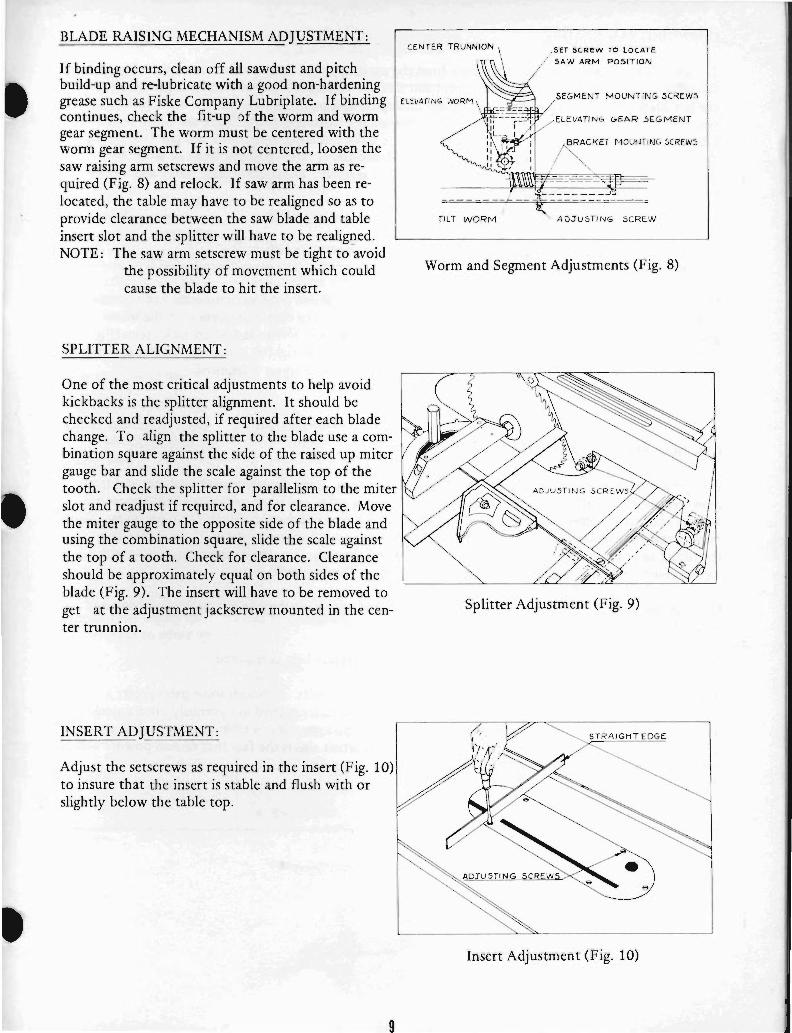
BLADE RAISING MECHANISM ADJUSTMENT:
If binding occurs, clean off all sawdust and pitch build-up and re-Iubricate with a good non-hardening grease such as Fiske Company Lubriplate. If binding continues, check the fit-up of the worm and worm gear segment. The worm must be centered with the worm gear segment. If it is not centered, loosen the saw raising arm setscrews and move the arm as required (Fig. 8) and relock. If saw arm has been relocated, the table may have to be realigned so as to provide clearance between the saw blade and table insert slot and the splitter will have to be realigI}ed. NOTE: The saw arm setscrew must be tight to avoid
the possibility of movement which could cause the blade to hit the insert.
SPLITTER ALIGNMENT :
One of the most critical adjustments to help avoid kickbacks is the splitter alignment. It should be checked and readjusted, if required after each blade change. To align the splitter to the blade use a combination square against the side of the raised up miter gauge bar and slide the scale against the top of the tooth. Check the splitter for parallelism to the miter slot and readjust if required, and for clearance. Move the miter gauge to the opposite side of the blade and using the combination square, slide the scale against the top of a tooth. Check for clearance. Clearance should be approximately equal on both sides of the blade (Fig. 9). The insert will have to be removed to get at the adjustment jackscrew mounted in the center trunnion.
INSERT ADJUSTMENT:
Adjust the setscrews as required in the insert (Fig. 10) to insure that the insert is stable and flush with or slightly below the table top.
9
ELEVATING WORM
rtLT WORM
, SET SCREW TO LOCATE
SAW ARM POSITION
SEGMENT tv10UNTIN G .5 CREW.5
ELEVATING G E AR 5 £ GMENT
A .KEf MOUNTING SCREWS
'11:'-- -------',.;
~ ADJuSTING SCR~W
Worm and Segment Adjustments (Fig. 8)
Splitter Adjustment (Fig. 9)
ST RA IGH TEDGE
Insert Adjustment (Fig. 10)
CHANGING SAW BLADES:
To change a saw blade, disconnect machine from the power source. Remove the table insert. Place the arbor wrench Ion the arbor nut (note left-hand threads) and use a block of wood wedged between the saw blade and table. Remove the arbor nut and collar and saw blade. Install new blade making sure the cutting edge of the teeth at the top face toward the front of the saw. Slid~ the collar on the arbor and start the arbor nut on the threads. Snug the arbor nut against the collar and saw blade using the wrench and holding the saw blade with the thumb and finger tips. Wedge a block of wood between the saw blade and table and tighten the arbor nut securely. Replace the table insert and reconnect the machine to power source.
TITLING MECHANISM ADJUSTMENT:
If binding occurs in the tilting mechanism, clean off the sawdust and pitch accumulation and regrease. If binding continues, check the alignment and readust as required to center of worm with the worm gear segment on the trunnion. If there is excessive play, loosen cap screws and adjust jackscrews (Fig. 8) clockwise to raise pinion. A tight mesh without binding is ideal. Retighten mounting ,screws and check over the 900 to 45 0 range of tilt for excessive play or binding. Readjust if required.
GENERAL MAINTENANCE:
Good saw operation requires periodic preventive maintenance. Keep the inside of the cabinet and trunnion area clean. A stiff brush will remove sawdust before it cakes and pitch or gum is easily removed with a commercial solvent or with a good oven cleaner. To accomplish this, remove the table by removing the three mounting screws and exposing the working mechanisms of the saw. After cleaning the tilting and raising worm and worm gear segments and the trunnions, grease these three areas with a good grade non-hardening grease such as Fiske Company "Lubriplate".
Check periodically for excessive end play in the tilting and raising mechanism and in the saw arbor and readjust as required.
Check periodically for belt tension and wear. Readjust or replace belt as required.
The table surface must be kept clean and free of rust for best results. Although some users prefer a wax coatipg, white talcum powder applied with a blackboard eraser rubbed in vigorously once a week will fill casting pores and :orm a moisture barrier. This method provides a table top that is slick and allows rust rings to be easily wiped from the surface. Important also is the fact that talcum powder will not stain wood or mar finishes as wax pickup does.
10

TROUBLE SHOOTING HINTS
TROUBLE POSSIBLE CAUSE REMEDY
Excessive 1. Tilt or raising clamp knobs not 1. Tighten knobs. vibration. tightened.
2. Blade out of balance. 2. Change blade.
3. Bad motor. 3. Replace motor.
Cut out-of-square 1. Miter gauge out of adjustment. 1. Reset stops and pointer. when crosscutting.
2. Miter slot misaligned. 2. Realign table.
Motor stalls or work 1. Excessive feed. 1. Reduce feed. piece binds or 2. Bad motor. 2. Replace motor. burns. 3. Dull or incorrect blade. 3. Replace blade.
4. Miter slot misaligned. 4. Realign miter slot. S. Fence misalignment. S. Realign fence.
Cuts not true at 900 1. Stop screws not set properly. 1. Readjust stop screws. or 4So
Tilt or saw raising hand- 1. Clamp knobs not released. 1. Unclamp. wheels difficult to 2. Worm and worm gear segment 2. Clean and regrease. turn. caked with sawdust and pitch.
3. Worm and worm gear segment 3. Realign worm and worm out of alignment. gear segment.
Motor overheats. 1. Motor overloaded. 1. Correct overload condition such as reducing the feed rate.
2. Improper cooling of motor. 2. Clean sawdust from fan and duct areas of motor.
Motor starts slowly or 1. Low voltage. 1. Request voltage check from fails to come up power company and correct
low voltage condition. 2. Centrifugal switch not operating. 2. Replace switch. 3. Bad motor. 3. Replace motor.
Motor fails to develop 1. Power line overloaded. 1. Correct overload condition. full power. 2. Undersize wires in supply 2. Increase supply wire size.
system. 3. Low voltage. 3. Request voltage check from
power company and correct low voltage condition.
4. Bad motor. 4. Replace motor.
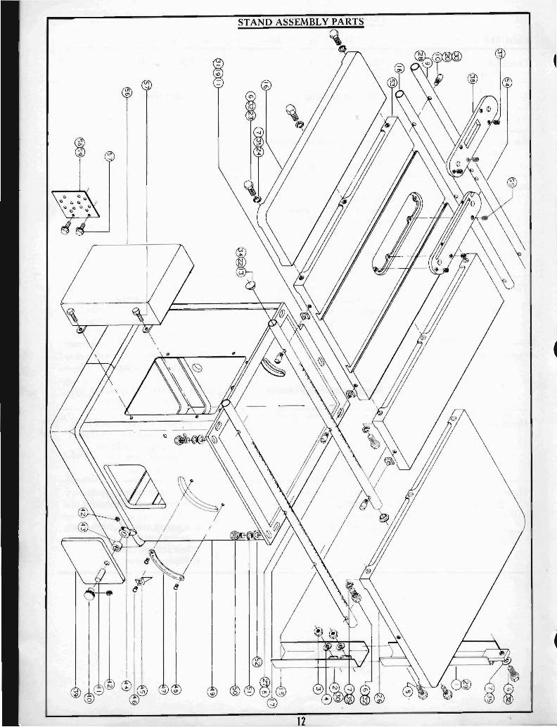
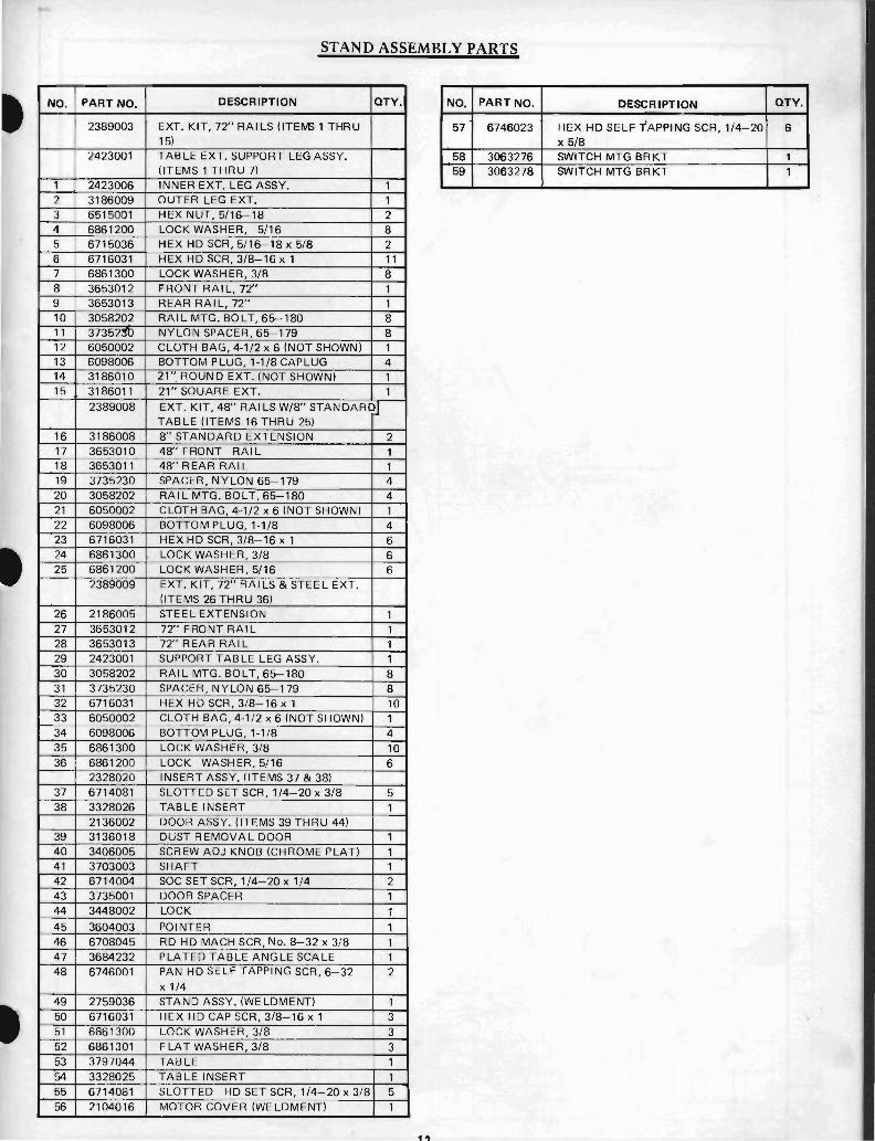
STAND ASSEMBLY PARTS
NO. PART NO. DESCRIPTION QTY. NO. PART NO. DESCRIPTION QTY.
2389003 EXT. KIT, 72" RAILS (ITEM> 1 THRU 57 6746023 HEX HD SELF TAPPING SCR,l/4-20 6 15) x 5/8
2423001 TABLE EXT. SUPPORT LEG ASSY. 58 3063276 SWITCH MTG BRKT 1 (ITEMS 1 THRU 7) 59 3063278 SWITCH MTG BRKT 1
1 2423006 INNER EXT. LEG ASSY. 1 2 3186009 OUTER LEG EXT. 1 3 6515001 HEX NUT, 5/16-18 2 4 6861200 LOCK WASHER, 5/16 8 5 6715036 HEX HD SCR, 5/16-18 x 5/8 2 6 6716031 HEX HD SCR, 3/8-16 xl 11 7 6861300 LOCK WASHER, 3/8 8 8 3653012 FRONT RAIL, 72" 1 9 3653013 REAR RAIL, 72" 1 10 3058202 RAI L MTG. BOLT, 65--180 8 11 37352~ NYLON SPACER, 65--179 8 12 6050002 CLOTH BAG, 4-1/2 x 6 (NOT SHOWN) 1 13 6098006 BOTTOM PLUG, 1-1/8 CAP LUG 4 14 3186010 21"ROUND EXT. (NOT SHOWN) 1 15 3186011 21" SQUARE EXT. 1
2389008 EXT. KIT, 48" RAILS W/8" STANDARD~ TABLE (ITEMS 16 THRU 25)
16 3186008 8" STANDARD EXTENSION 2 17 3653010 48" FRONT RAI L 1 18 3653011 48" REAR RAIL 1 19 3735230 SPACER, NYLON 65-179 4 20 3058202 RAI L MTG. BOLT, 65--180 4 21 6050002 CLOTH BAG, 4-1/2 x 6 (NOT SHOWN) 1 22 6098006 BOTTOM PLUG, 1-1/8 4 23 6716031 HEX HD SCR, 3/8-16 x 1 6 24 6861300 LOCK WASHER, 3/8 6 25 6861200 LOCK WASHER, 5/16 6
2389009 EXT. KIT, 72" RAI LS & STEE L EXT. (ITEMS 26 THRU 36)
26 2186005 STEEL EXTENSION 1 27 3653012 72" FRONT RAIL 1 28 3653013 72" REAR RAIL 1 29 2423001 SUPPORT TABLE LEG ASSY. 1 30 3058202 RAI L MTG. BOLT, 65--180 8 31 3735230 SPACER, NYLON 65-179 8 32 6716031 HEX HD SCR, 3/8-16 xl 10 33 6050002 CLOTH BAG, 4-1/2 x 6 (NOT SHOWN) 1 34 6098006 BOTTOM PLUG, 1-1/8 4 35 6861300 LOCK WASHER, 3/8 10 36 6861200 LOCK WASHER,5/16 6
2328020 INSERT ASSY. (ITEMS 37 & 38) 37 6714081 SLOTTED SET SCR, 1/4-20 x 3/8 5 38 3328026 TABLE INSERT 1
2136002 DOOR ASSY. (ITEMS 39 THRU 44) 39 3136018 DUST REMOVAL DOOR 1 40 3406005 SCREW ADJ KNOB (CHROME PLAT) 1 41 3703003 SHAFT 1 42 6714004 SOC SET SCR, 1/4-20 x 1/4 2 43 3735001 DOOR SPACER 1 44 3448002 LOCK 1 45 3604003 POINTER 1 46 6708045 RD HD MACH SCR, No. 8-32 x 3/8 1 47 3684232 PLATED TABLE ANGLE SCALE 1 48 6746001 PAN HD SELF TAPPING SCR, 6-32 2
x 1/4 49 2759036 STAND ASSY. (WELDMENT) 1 50 6716031 HEX HD CAP SCR, 3/8-16 xl 3 51 6861300 LOCK WASHER, 3/8 3 52 6861301 FLAT WASHER, 3/8 3 53 3797044 TABLE 1 54 3328025 TABLE INSERT 1 55 6714081 SLOTTED HD SET SCR, 1/4-20 x 3/8 5 56 2104016 MOTOR COVER (WELDMENT) 1

. ,
NO.
. 1 2 3 4 5 6 7 8 9 10 11 12
13 14 15 16 17 18 19
20
21 22 23
24 25 26
27 28 29 30 31 32 33 34 35 36 37 38
39 40 41 42
43 44
45 46
PART NO.
2025002
2024008
2024001 3700011 3838006 3737206 3737207 6060008 3025042 3237010 6717018 6717019 6861401 6861400 6716009 2701001
2865001
3865001 3701031 6626031 6420002 3096244 3065006 6715016
6861901 2271008
6624006 3268201 3271039 2865002
3865001 3701032 6626031 2695004
3582009 6714004 3406018 2087001 6715033 6861200 3810018 3480010 3717017 3838004 3844204 3530006
3096044 3810023 3735075 3717018 3717058
3717060 6715144 6077004
3711005 6080041
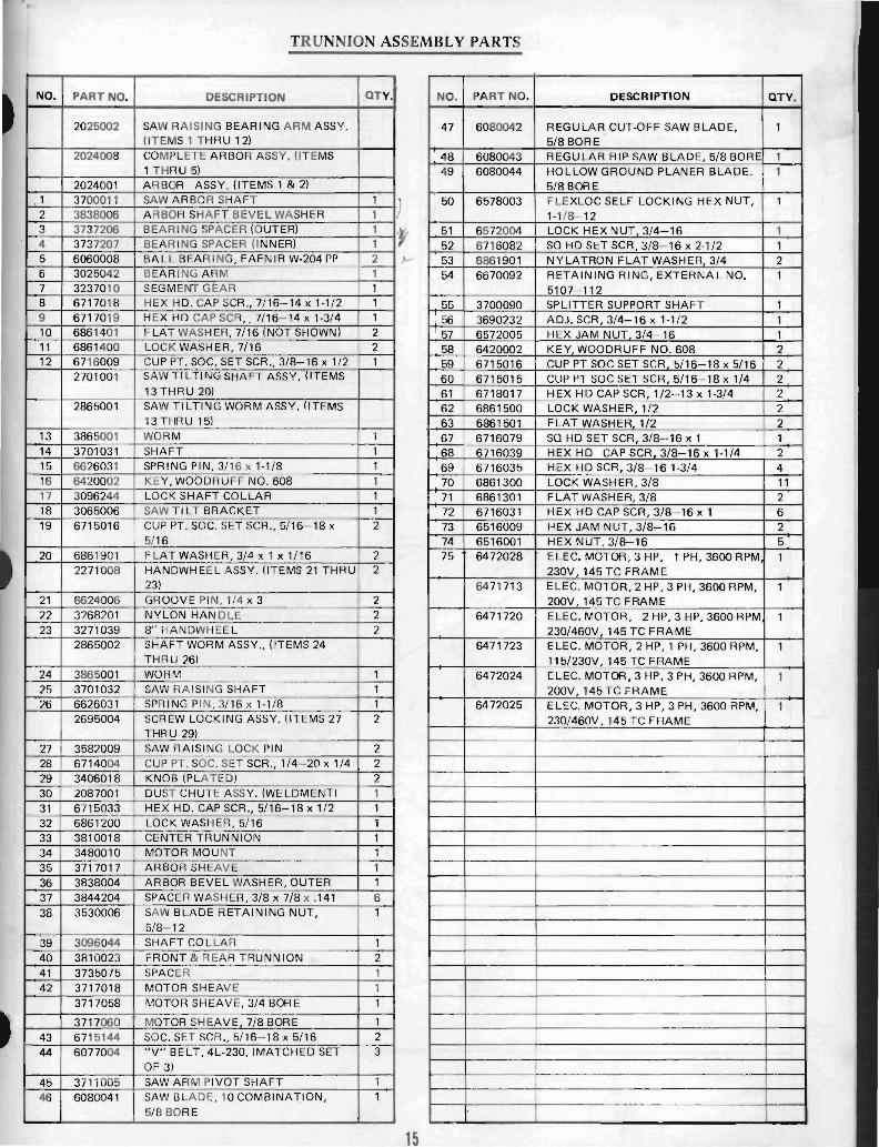
TRUNNION ASSEMBLY PARTS
DESCRIPTION QTY. NO. PART NO.
SAW RAISING BEARING ARM ASSY. 47 6080042 (ITEMS 1 THRU 12) COMPLETE ARBOR ASSY. (ITEMS 48 6080043 1 THRU 5) 49 6080044 ARBOR ASSY. (ITEMS 1 & 2)
50 6578003 SAW ARBOR SHAFT 1 ) ARBOR SHAFT BEVEL WASHER 1 BEARING SPACER (OUTER) 1 51 6572004 BEARING SPACER (INNER) 1 52 6716082 BALL BEARING, FAFNIR W-204 PP 2 53 6861901 BEARING ARM 1 54 6670092 SEGMENT GEAR 1 HEX HD. CAP SCR., 7/16-14 x 1-1/2 1 55 3700090 HEX HD CAP SCR. , 7/16-14 x 1-3/4 1 .1 56 3690232 FLAT WASHER, 7/16 (NOT SHOWN) 2 ' 57 6572005 LOCK WASHER, 7/16 2 58 6420002 CUP PT. SOC. SET SCR., 3/8-16 x 1/2 1 59 6715016 SAW TI L TI NG SHAFT ASSY. (ITEMS 60 6715015 13 THRU 20) 61 6718017 SAW TI LTING WORM ASSY. (ITEMS 62 6861500 13 THRU 15) 63 6861501 WORM 1 67 6716079 SHAFT 1 68 6716039 SPRING PIN, 3/16 x 1-1/8 1 69 6716035 KEY. WOODRUFF NO. 608 1 70 6861300 LOCK SHAFT COLLAR 1 71 6861301 SAW TI LT BRACKET 1 72 6716031 CUP PT. SOC. SET SCR., 5/16-18 x 2 73 6516009 5/16 74 6516001 FLAT WASHER, 3/4 x 1 x 1/16 2 75 6472028 HANDWHEEL ASSY. (ITEMS 21 THRU 2 23) 6471713 GROOVE PIN, 1/4 x 3 2 NYLON HAN DLE 2 6471720 8" HANDWHEEL 2 SHAFT WORM ASSY., (ITEMS 24 6471723 THRU 26) WORM 1 6472024 SAW RAISING SHAFT 1 SPRING PIN, 3/16 x 1-1/8 1 6472025 SCREW LOCKING ASSY. (ITEMS 27 2 THRU 29) SAW RAISING LOCK PIN 2 CUP PT. SOC. SET SCR., 1/4-20 x 1/4 2 KNOB (PLATED) 2 DUST CHUTE ASSY. (WELDMENT) 1 HEX HD. CAP seR., 5/16-18 x 1/2 1 LOCK WASHER, 5/16 1 CENTER TRUNNION 1 MOTOR MOUNT 1 ARBOR SHEAVE 1 ARBOR BEVEL WASHER, OUTER 1 SPACER WASHER, 3/8 x 7/8 x .141 6 SAW BLADE RETAINING NUT, 1 5/8-12 SHAFT COLLAR 1 FRONT & REAR TRUNNION 2 SPACER 1 MOTOR SHEAVE 1 MOTOR SHEAVE, 3/4 BORE 1
MOTOR SHEAVE 7/8 BORE 1 SOC. SET SCR., 5/16-18 x 5/16 2 "V" BELT, 4L-230, (MATCHED SET 3 OF 3) SAW ARM PIVOT SHAFT 1 SAW BLADE, 10COMBINA-Y:ION, 1 5/8 BORE
15
DESCRIPTION QTY.
REGULAR: CUT-OFF SAW BLADE, 1 5/8 BORE REGULAR RIP SAW BLADE, 5/8 BORE 1 HOLLOW GROUND PLANER BLADE. 1 5/8 BORE FLEXLOC SELF LOCKING HEX NUT, 1 1-1/8-12 LOCK HEX NUT 3/4-16 1 SO HD SET SCR. 3/8-16 x 2-1/2 1 NYLATRON FLAT WASHER, 3/4 2 RETAINING RING, EXTERNAL NO. 1 5107-112 SPLITTER SUPPORT SHAFT 1 ADJ. SCR, 3/4-16 x 1-1/2 1 HEX JAM NUT 3/4-16 1 KEY WOODRUFF NO. 608 2 CUP PT SOC SET SCR 5/16-18 x 5/16 2 CUP PT SOC SET SC·R, 5/16-18 x 1/4 2 HEX HD CAP SCR, 1/2-13 x 1-3/4 2 LOCK WASHER, 1/2 2 FLAT WASHER 1/2 2 SO HD SET SCR,3/8-16 x 1 1 HEX HD CAP SCR 3/8-16 x 1-1/4 2 HEX HD SCR, 3/8-16 1-3/4 4 LOCK WASHER, 3/8 11 FLAT WASHER, 3/8 2 HEX HD CAP SCR, 3/8-16 x 1 6 HEX JAM NUT, 3/8-16 2 HEX NUT, 3/8-16 5 ELEC. MOTOR, 3 HP, 1 PH, 3600 RPM 1 230V, 145TC FRAME ELEC. MOTOR, 2 HP, 3 PH, 3600 RPM, 1 200V, 145 TC FRAME ELEC. MOTOR, 2 HP, 3 HP, 3600 RPM · 1 230/460V, 145 TC FRAME ELEC. MOTOR, 2 HP, 1 PH, 3600 RPM, 1 115/230V 145 TC FRAME ELEC. MOTOR, 3 HP, 3 PH, 3600 RPM, 1 200V, 145 TC FRAME ELEC. MOTOR, 3 HP, 3 PH, 3600 RPM, 1 230/460V. 145 TC FRAME

NO. PART NO.
2440001
1 3063027 2 3448001 3 6626038 4 6514001 5 6714072
2078001
2268017
6 3670039 ~
7 3406201 2586001
8 3586007 9 3406017 10 6714004 11 3064033 12 3076001 13 3076227
FENCE ASSEMBLY
DESCRIPTION
REAR FENCE LOCK ASSY. (ITEMS 1 THRU 5) REAR FENCE MOUNTING BRACKET REAR LOCK SPRING PIN, 1/4 xl HEX NUT, 1/4-20 FLAT PT sa HD SET SCR, 1/4-20 x 1 FENCE ASSY CARRIAGE, (ITEMS 6 Tj-iRU 25)
I~~RIAGE FENCE HANDLE ASSY, (ITEMS 6 & 7) ZINC PLATED CAM HANDLE ROD NYLON TEARDROP KNOB PINION ASSY.,(lTEIVE 8THRU 10) FENCE CARRIAGE PINION KNOB CUP PT SOC SET SCR, 1/4-20 x 1/4 BRACKET FRONT LOCK CAM REAR LOCK CAM
OTY. NO. PART NO. , DESCRIPTION
1 1 1 1 1 2
2 2
1 1 1 1 1
1
14 3196002 CARRIAGE FENCE TA·74 15 3604005 ALUM. POINTER, .051 T.A. 16 6706037 RD HD MACH SCR, No. 6-32 x 3/16 17 6626050 SPRING PIN, 3/8 x 1·3/4 18 6626038 SPRING PIN, 1/4 xl 19 6813060 COMPo SPRING, No. 65-2, 7/16 x 1·5/1 20 6718090 FLAT PT SOC SET SCR, 1/2-13 x 3/4 21 6861100 LOCK WASHER, . 1/4 22 6714026 FIL HD CAP SCR, 1/4-20 x 5/8 23 6714081 SLOT HD SET SCR, 1/4-20 x 3/8 . 24 6714087 HALF DOG PT SOC SET SCR, 1/4-20
x 1/4 25 6716003 CUP PT SOC SET SCR, 3/8-16 x 3/8 26 6626001 SPRING PIN, 1/8 x 5/8 27 3670058 LOCK PIN 28 6813068 COMPo SPRING, 9/16 x 2 29 6680019 RIVET, .188 x 1/2 x 3/8 30 3196004 FENCE 31 6716012 SOC HD CAP SCR, 3/8-16 1 32 6715020 SOC HD CAP SCR. 5/16-18 xl
~--------------------------------~~
------------------------~GG
\----------------~@9
--~~------------------~~
'-------------@!
16
OTY.
1 1 1 2 1
61 1 1 1 1 1 1
2 1 1 1 1 1 1 2
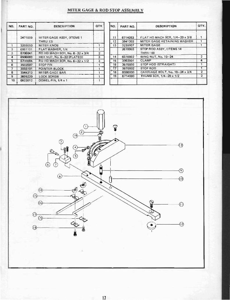
MITER GAGE & ROD STOP ASSEMBLY
NO. PART NO. DESCRIPTION QTY. NO. PART NO. DESCRIPTION QTY.
2471009 MITER GAGE ASSY, (ITEMS 1 11 6714053 FLAT HD MACH SCR, 1/4-20 x 3/8 1 THRU 13) 12 3841202 MITER GAGE RETAINING WASHER 1
1 3268050 MITER KNOB 1 13 3230007 MITER GAGE 1 2 6861101 FLAT WASHER, 1/4 1 2670003 STOP ROD ASSY, (ITEMS 14 3 6706041 RD HD MACH SCR, No. 6-32 x 3/4 2 THRU 18) 4 6506003 HEX NUT, No. 6-32 (PLATED) 3 14 6510002 WING NUT, No. 10-24 2 5 6706094 RD HD MACH SCR , No. 6-32 x 1/2 3 15 3092001 CLAMP 4
6 3582097 STOP PIN 1 16 3670003 STOP ROD (STRAIGHT) 1 7 3055101 POINTER BLOCK 1 17 3670002 STOP ROD 1
8 3044313 MITER GAGE BAR 1 18 6086000 CARRIAGE BOLT, No. 10-24 x 3/4 2
9 3695220 LOCK SCREW 1 19 6714080 THUMB SCR, 1/4-20 x 1/2 2
10 6623012 DOWEL PIN, 1/4 x 1 1
0-@®
@
a-I
®
~ @
~ @ ~V @ w/ @ ([J)
@ .
~~ . @
@ -i @
17

OVERHANGING GUARD ASSEMBLY PARTS
NO. 1 PART NO. DESCRIPTION
2250117 OVERHANGING GUARD ASSY, (ITEMS 1 THRU 25)
1 6680009 FL HDRIVET 5/16x7/8 2 6680005 FL HD RIVET, 1/4 x 7/8 3 3046202 PIVOT SPACER BEARING 4 3250113 BLADE GUARD, R. H. 5 3064072 TUBE HOLDING BRACKET 6 3025036 PIVOT GUARD ARM, R. H. 7 3096003 COLLAR 8 6715133 THUMB'SCREW, 5/16-18 x 1 9 3816011 MOUNTING TUBE 10 6514001 HEX NUT, 1/4-20 11 6514012 FLEX-LOC NUT, 1/4-20 12 6714063 RD HD MACH SCR, 1/4-20 1/2 13 3791001 TUBE SUPPORT 14 3750011 SPLITTER
15 6861101 FLAT WASHER, 1/4 16 6714131 HEX HD CAP SCR, 1/4-20 x 5/8 17 3581006 ANTI-KICKBACK PAWL
~
0~-~-f-----
®--
, QTY. NO.
18 19
2 20 2 21 2 22 1 1 1 23 4 24 4 25 1 2 1 26 2 27 1 28 1 29 4 30 1 31 2 32
18
PART NO. , DESCRIPTION QTY.
3025037 PIVOT GUARD ARM, L. H. 1 3250114 BLADE GUARD, L. H. 1 6706038 RD HD MACH SCR, No. 6- 32 x 1/2 3 3595061 SAFETY PLATE 1 6626002 SPRING PIN, 1/8 x 3/8 2 2695003 LOCK ASSY SCREW (ITEMS 23
THRU 25) 3406016 HANDLE KNOB 1 3695001 LOCK SCREW 1 3268002 HANDLE 1 2787008 SPLITTER REAR SUPPORT ASSY,
(ITEMS 26 THRU 32) 2406001 KNOB ASSY 1 3690232 ADJUST SCREW, 3/4-16 x 1-1/2 1 6572005 HEX JAM NUT, 3/4-16 1 3776050 REAR SPLITTER SUPPORT 1 6861200 LOCK WASHER, 5/16 3 6715034 HEX HD CAP SCR, 5/16-18 x 1-1/4 3 3700090 SPLITTER SUPPORT SHAFT 1
~-------~~
---------------------~~ -----------------~ ----------------~~
®A 6 ,/' I'T----:::------------"
® -----------{ 7
~---G
NO.
1 2 3 4 5 6 7
8 9 10 11 12
13 14
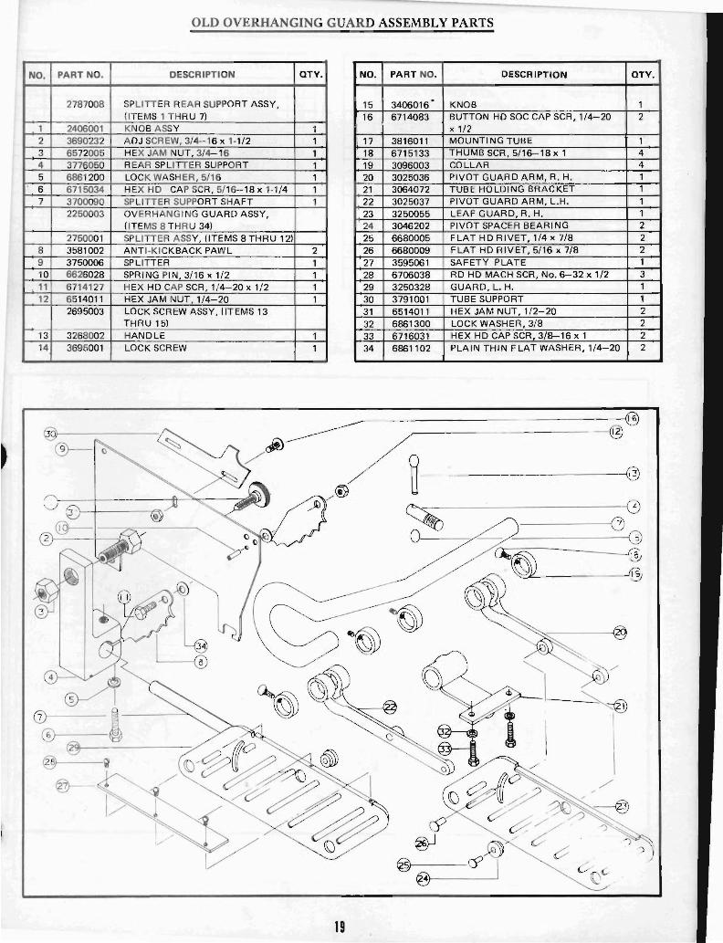
OLD OVERHANGING GUARD ASSEMBLY PARTS
PART NO. DESCRIPTION QTY. NO. PART NO. DESCRIPTION QTY.
2787008 SPLITTER REAR SUPPORT ASSY, 15 3406016· KNOB (IT EMS 1 THRU 7) 16 6714083 BUTTON HD SOC CAP SCR, 1/4-20 2
2406001 KNOB A SSY 1 x 1/2 3690232 ADJ SCREW, 3/4- 16 x 1-1/2 1 17 3816011 MOUNTI NG TUBE 6572005 HEX JAM NUT, 3/4-16 1 18 6715133 THUMB SCR, 5/16-18 x 1 4 3776050 REAR SPLITTER SUPPORT 1 19 3096003 COLLAR 4 6861200 LOCK WASHER , 5/16 1 20 3025036 PIVOT GUARD ARM, R. H. 6715034 HEX HD CAP SCR, 5/16-18 x 1-1/4 1 21 3064072 TUBE HOLDING BRACKET 3700090 SPLITTER SUPPORT SHAFT 1 22 3025037 PIVOT GUARD ARM, L.H. 2250003 OVERHANGING GUARD ASSY, 23 3250055 LEAF GUARD, R. H. 1
(ITEMS 8 THRU 34) 24 3046202 PIVOT SPACER BEARI NG 2 2750001 SPLITTER ASSY, (ITEMS 8 THRU 12) 25 6680005 FLAT HD RIVET, 1/4 x 7/8 2 3581002 ANTI -KICKBACK PAWL 2 26 6680009 FLAT HD RIVET, 5/16 x 7/8 2 3750006 SPLITTER 1 27 3595061 SAFETY PLATE 1 6626028 SPRING PIN 3/16 x 1/2 1 28 6706038 RD HD MACH SCR, No. 6-32 x 1/2 3 6714127 HEX HD CAP SCR , 1/4-20 x 1/2 1 29 3250328 GUARD, L. H. 6514011 HEX JAM NUT, 1/4-20 1 30 3791001 TUBE SUPPORT 2695003 LOCK SCREW ASSY, (ITEMS 13 31 6514011 HEX JAM NUT, 1/2-20 2
THRU 15) 32 6861300 LOCK WASHER, 3/8 2 3268002 HANDLE 1 33 6716031 HEX HD CAP SCR, 3/8-16 x 1 2 3695001 LOCK SCREW 1 34 6861102 PLAIN THIN FLAT WASHER, 1/4-20 2
------------------------------~~
J9J---------- /, @ / ~ ~ @
® U \---+-----ft---'~--~fV! It'. ./ f7\
/"' ~-----------\!:;
19
~ G(]
@f----@--- ---'
~~------------~ o
~~----------~~
~---------1@

SPLITTER AND GUARD ASSEMBLY PARTS
NO. PART NO. DESCRIPTION OTY. ,
2787008 SPLITTER REAR SUPPORT ASSY, (ITEMS 1 THRU 7)
1 6715034 HEX HD CAP SCR, 5/16-18 x 1·1/4 1 2 6861200 LOCK WASHER, 5/16 1 3 3776050 SPLITTER REAR SUPPORT 1 4 6572005 HEX JAM NUT, 3/4-16 1 5 3690232 ADJUST SCR, 3/4-16 x 1·1/2 1 6 2406001 KNOB ASSY 1 7 3700090 SPLITTER SUPPORT SHAFT 1
2250116 GUARD AND SPLITTER ASSY, (ITEMS 8 THRU 28)
8 6861101 FLAT WASHER, 1/4 2
9 6714158 HEX HD CAP SCR, 1/4-20 x 5/8 1
10 6714192 F L HD SOC SCR, 1/4-20 x 7/8 10 11 3250112 BLADE GUARD 2 12 3838015 PIVOT WASHER 4
J
0l-----~ I (0f----£ #
~~---------~
~. -----------------------~~ , ) t::.j- f.?\~ @'-../ ~
20
NO.
13 14 15 16 17 18 19 20 21
122 23 24 25 26 27 28
PART NO. DESCRIPTION
6514012 LOCK NUT, 1/4-20 6626029 SPRING PIN, 3/16 x 1
6626050 SPRING PIN, 3/8 x 1·3/4
3720018 GUARD SHIELD
6710032 RD HD MACH SCR, No. 10-24 x 1/4 3720017 FRONT SHIELD
6714053 F L HD MACH SCR, No. 10-24 x 3/8
3055095 PIVOT BLOCK 3025074 PIVOT ARM 3070108 PIVOT BUSHING
6514001 HEX NUT, 1/4-20
3581006 ANTI · KICKBACK PAWL 3044307 SPLITTER BAR
3750011 SPLITTER 3735203 SPACER 3837206 WASHER
-----------------------.~ ~---------------------~,~
'" )------~@ c::::,.
/~------------- 6
OTY.'
9 1 1 1 2 1 2 1 4 8 2 2 1 1 2 5

OLD SPLITTER & GUARD ASSEMBLY PARTS
NO. PART NO. DESCRIPTION
2787008 SPLITTER REAR SUPPORT ASSY, -- (ITEMS 1 THRU 7) 1 2406001 KNOB ASSV 2 3690232 ADJ SCREW, 3/4-16 x 1·1/2 3 6572005 HEX JAM NUT,,3/4-16 4 3776050 SPLITTERSUPPORT,REAR 5 6861200 LOCK WASHER, 5/16 6 6715034 HEX HD CAP SCR, 5/16-18 x 1-1/4 7 3700090 SPLITTER SUPPORT SHAFT
2250002 BLADE & SPLITTER GUARD ASSY, , -. (ITEMS 8 THRU 25)
2025001 PIVOT ARM ASSY, (ITEMS 8 THRU 10)
8 3046201 BEARING 9 3584216 PIVOT PIN 10 3025004 ALUMINUM ARM
2750001 SPLITTER ASSV, (ITEMS 11 THRU 15
0-(j)~~~-
®----~'i?j
I ®I----£ {@/ @ /
@-------------..:"
OTV.
1 1 1 1 1 1 1
4
4 4 2
NO.
11 12 13 14 15 16 17 18 19 20 21
22
23 24 25
21
PART NO. DESCRIPTION
3581002 ANTI·KICKBACK PAWL 3750006 SPLITTER 6626028 SPRING PIN, 3/16 x 1/2 6714127 HEX HD CAP SCR, 1/4-20 x 1/2 6514011 HEX JAM NUT, 1/4-2 3250056 LEAF GUARD, L. H. 3250055 LEAF GUARD, R. H. 3025041 SUPPORT ARM 3584217 PIVOT PIN 6626050 SPRING PIN, 3/8 x 1·3/4 6670097 RETAINING RING. TRUARC ·
NO. 5144-37 6414060 HEX SOC CAP FLAT HD SCR.
1/4-20 x 1 6514005 HEX NUT, 1/4-20 3735203 BEARING SPACER 6861102 PLAIN THIN FLAT WASHER. 1/4-20
,------------~ @)
-------1@
\\-----@
~-------@
OTV.
2
2 1 8
2
2 2 2
--
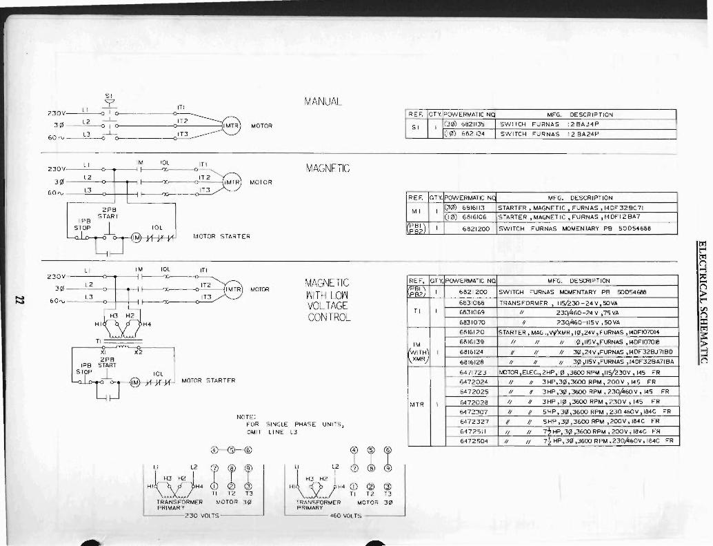
SI
9'
''0' ~: ~ B=e 3¢ 0-1- IT2 60 'V L3 -1-1 MTR MOTOR
o IT3
230V L I 1M 10L
,:~ ~:: 11 :~ "NO'
2PB IPB START
STOP 10L
MOTOR START ER
LI 1M 10L ITI
":: ~~: 11 :~ MO~ 60",
IP8 STOP
HI
TI
X2
H4
10L MOTOR STARTER
NOTE:
MANUAL
MAGNETIC
MAQ\JETIC ~ITH Lrn VOLTAGE CONTROL
FOR SINGLE PHASE UNITS, OMIT LINE L3
II L2
HI~H4 TRANSFORMER PRIMARY
@---@----®
I I I TI T2 13
MOTOR 3!l1
'------230 VOLTS------'
I ~ cr lI\2:J H3H2
L2
7@®
HI H4 ~ @ Q)
TRANSFORMER I T2 T3 PRIMARY MOTOR 30
'------ 460 VOl TS --------'
~
REF. OTY. POWERMATIC NC
SI I (30) 6821135
(I¢) 6821134
REF. OTY. POWERMATIC NC
MI I (3¢) 6816113
(i 0) 6816106
PBI) PB2
I 6821200
REF, (lTY, PONERMATIC NQ
~~k) I 6621200
6831066 TI I 6831069
6831070
6816120
1M 6816139
WITH) I 6816124 \XMR 6616128
6471723
6472024
6472025
MTR I 6472028
6472307
6472327
6472511
6472504
MFG. DESCRIPTION ,
SWITCH FURNAS 12 BA34P
SWITCH FURNAS 12 BA24P
MFG. DESCRIPTION
STARTER. MAGNETIC, FURNAS, 14DF328C71
STARTER, MAGNET IC ,FURNAS, 14DFI2 8A7
SWITCH FURNAS MOMENTARY P8 50054666 --
MFG. DESCRIPTION
SWITCH FURNAS MOMENTARY PB S0054668
TRANSFORMER, 11030 -24 V, SOVA
II 230,460 -24 V ,75 VA
II 230f\60-115V,SOVA
STARTER, MAG .,'l'(xMR ,1(1,24V, FURNAS ,14DFI07014
II II II 1!jl,1I5V,FURNAS ,I4DFI07018
1/ // II 3¢,24V,FURNAS ,I40F32BJ71BO
II II II 3!il ,1I5V ,FURNAS, 140F32BA71BA
MJTOR,ELEG.,2HP,I!il ,36C1O RPM ,II 5/.2:30 V ,145 FR
II 1/ 3HP.3!il,36C1O RPM, 200V ,145 FR
II , 3 HP.3!1l ,3600 RPM, 230,,460 V ,145 FR
II /I 3HP,I!il ,3600 RPM, 230V , 145 FR
II 1/ 5HP,3¢,36oo RPM ,230 460V,I64C FR
1/ 1/ 5HP .3!jl ,3600 RPM ,200V ,I64C FR
II II 7-2 HP. 3!jl ,3600 RPM. ZOO V ; 184C FR
II II 72HP,3¢,3600R~,230,460V,IB4C FR
~ t"" ~ ~ ~ ~ -~ > t"" ~ ~ ::c ~
~ -~

notes

j
POWERMATIC r.:JOUDAILLE, INC. McMinnvil le, Tennessee 37110