Embed Size (px)
Citation preview

3A0293GEN
Instructions-Parts
Air Controls
Air controls for light and heavy duty Xtreme® Sprayer carts. For professional use only.
24E025, 24Y396Air Controls for Light Duty Xtreme Package Carts
24E013, 24Y101Air Controls for Heavy Duty Xtreme Package Carts
125 psi (0.86 MPa, 8.6 bar) Maximum Air Working Pressure depending on relief valve selected.
Important Safety InstructionsRead all warnings and instructions in this manualand the Xtreme Packages manual. Save theseinstructions.
24Y101
r_24e013_3A0293_1a
24W593, 24W040Air Controls for Xtreme XL Cart or Wall Mount Packages
244841Accessory lubricator kit for Xtreme or Xtreme XL Packages
Installation
2 3A0293G
Installation
Prepare the SiteNOTE: Always use Genuine Graco Parts and Acces-sories, available from your Graco distributor. If yousupply your own accessories, be sure they are ade-quately sized and pressure rated for your system.
Bring a compressed air supply line from the air com-pressor to the pump location. Be sure all air hoses areproperly sized and pressure-rated for your system. Useonly electrically conductive hoses. The air hose shouldhave a 3/4 npsm(m) thread. Before installing any air linecomponents, blow out the air lines to remove scale andother debris. Use pipe compound or tape sparingly andonly on male threads.
Install a bleed-type shutoff valve in the air line upstreamfrom all other air line components, to isolate them forservicing.
Kit Components (page 7)
Bleed-Type Master Air Valve (3)
Relieve air trapped between it and the air motor whenthe valve is closed. Be sure the bleed valve is easilyaccessible from the pump, and is located downstreamfrom the air filter/regulator (1). FIG. 2
Air Filter/Regulator (1)
Controls pump speed and outlet pressure by adjustingthe air pressure to the pump. It also removes harmfuldirt and moisture from the compressed air supply.Locate the regulator as close as possible to the equip-ment it serves, but upstream from the bleed-type mas-ter air valve (3). Install the regulator in the air line so theair flow is in the direction of the arrow stamped on thebody. FIG. 2.
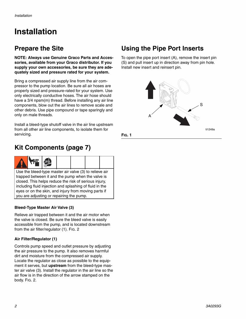
Using the Pipe Port InsertsTo open the pipe port insert (A), remove the insert pin(S) and pull insert up in direction away from pin hole.Install new insert and reinsert pin.
Use the bleed-type master air valve (3) to relieve airtrapped between it and the pump when the valve isclosed. This helps reduce the risk of serious injury,including fluid injection and splashing of fluid in theeyes or on the skin, and injury from moving parts ifyou are adjusting or repairing the pump.
FIG. 1
ti1249a
A
S

Installation
3A0293G 3
Adding a Lubricator (Accessory)
To add an accessory air line lubricator to the kit, youmust order Part No. 244841 Lubricator Accessory Kit.
1. Remove filter/regulator from mount bracket.
2. Remove the pin (B) from the outlet of the filter/regu-lator. FIG. 2.
3. Remove regulator cover.
4. Slide the threaded end insert off (13)with outlet fit-tings still attached.
5. Install the modular connector (2a) (with o-rings andgrease provided) between the filter/regulator andthe lubricator (L).
6. Install the threaded end insert (13) onto the outlet ofthe lubricator (L) with o-ring and grease.
7. Install the three retaining pins (B).
NOTE: On some configurations install the 3/4” nptfxf elbow with the 3/4” npt fxm elbow supplied withkit 244841, refer to instructions (form 406512)included with kit.
The lubricator meters oil into the moving air stream toautomatically lubricate air-operated motors. A manualadjustment in the housing (F), Fig. 2, sets the oil driprate into the air stream, which can be monitored througha sight glass. One to two drops of oil per minute is com-mon. Use an oil rated at 50 to 200 SUS (ISO grade 7 to46) at 100°F (38°C), such as Graco motor oil, Part No.202659.
Refill Lubricator
1. Unscrew the fill plug (L, FIG. 2) and pour in the oil.The lubricator’s capacity is 7 oz. (0.2 liter).
2. Check the oil level with the side sight glass. Thelubricator can be refilled with the system pressur-ized. However, always relieve the system pres-sure before removing the bowl for any reason.
FIG. 2
BB
2a
1
4
13
r_24e025_3A0293_4a

Operation
4 3A0293G
Operation
Pressure Relief Procedure
1. Lock the gun trigger safety.
2. Close all bleed-type master air valves, including thebleed-type master air valve (3), supplied in your sys-tem. FIG. 2.
3. Turn the regulator T-handle all the way counterclock-wise if you are removing the air filter/regulator (1)bowl, or servicing the air filter/regulator.
4. Open any fluid shutoff valves.
5. Unlock the gun trigger safety.
6. Hold a metal part of the gun firmly to the side of agrounded metal pail, and trigger the gun to relievepressure.
7. Lock the gun trigger safety.
8. Open any fluid drain valves (required in your sys-tem), having a container ready to catch the drain-age.
9. Leave the drain valve(s) open until you are ready tospray again.
If you suspect that the spray tip or hose is completelyclogged, or that pressure has not been fully relievedafter following the steps above, very slowly loosen thetip guard retaining nut or hose end coupling and relievepressure gradually, then loosen completely. Now clearthe tip or hose.
Adjusting the Air Regulator
1. To increase the regulated air pressure, turn theT-handle clockwise.
2. To decrease the regulated air pressure, turn theT-handle counterclockwise.
3. To lock the regulator setting, tighten the jam nut.
4. Slowly open the air filter/regulator (1), FIG. 2. Usethe filter/regulator to control pump speed and fluidpressure. Always use the lowest air pressure neces-sary to get the desired results. Higher pressurescause premature tip and pump wear.
Use the bleed-type master air valve (3) to relieve airtrapped between it and the pump when the valve isclosed. This helps reduce the risk of serious injury,including fluid injection and splashing of fluid in theeyes or on the skin, and injury from moving parts ifyou are adjusting or repairing the pump.

Repair
3A0293G 5
Repair
Air RegulatorRepair Kits are available. Refer to page 6.
Every day, drain contaminants from the bowl beforereaching the baffle level by opening the drain (D) at thebottom of the bowl (B). See FIG. 3.
Clean the air filter regularly to maximize filtering effi-ciency and to avoid excessive pressure drop. Fullyrelieve pressure to remove the bowl (B).
Clean the filter element and bowl using detergent andwater or denatured alcohol. Use compressed air to blowout the filter body. Blow the filter element out from theinside.
Service the regulator, if the regulator fails to operate,operates roughly, or vibrates. Inspect all parts for wearor damage. Replace damaged parts. Refer to page 7.
Lubricate the bearing area, all o-rings, adjusting screwthreads, and spring ends with no. 2 lithium-base grease.See. FIG. 3. Reassemble the regulator.
Lubricator Service (Accessory)An accessory Lubricator Kit is available. Order Part No.244841. Repair Kits are available (refer to page 7) for anaccessory lubricator.
Clean the lubricator regularly to maximize efficiency.Fully relieve pressure and remove the lubricator fromthe air line.
Disassemble the lubricator.
Clean the parts with detergent and water or denaturedalcohol. Wipe dry with a clean, soft cloth.
Use compressed air to blow dirt and contaminants out ofthe lubricator body. Inspect all parts for wear or damage.Replace damaged parts.
Clean the sight glass (S) thoroughly. See Fig. 4. Do notleave solvent residue in the sight glass as it may attackor weaken the glass. If the sight glass appears dam-aged, replace it immediately.
Reassemble the lubricator.

Repair Kits
6 3A0293G
Repair Kits
116521, 17C498Air Filter/Regulator
C11034 Lubricator
FIG. 3: 116521, 17C498 Repair Kits
1
Lubricate with no. 2lithium-base grease.
1
1
1
1
D
B
40 Micron FilterElement Kit 116635
Bowl ReplacementKit 116672
Regulator RepairKit 116634
TI1251A
FIG. 4: C11034 Repair Kits
Sight Dome RepairKit 116670
BowlRepair Kit116672
TI1252A

Parts
3A0293G 7
Parts
24Y101 Xtreme Heavy Duty Cart Air Controls, Series C
24E013 Xtreme Heavy Duty Cart Air Controls, Series A and B
* Not included with air controls. Replace with appropriate part number from table below according to pump ratio.
Ref.No. Part No. Description Qty.1 116521 REGULATOR, filter, air 13 17B747 BRACKET 14 103833 SCREW, mach, pan hd 45 113429 COUPLING 16 113430 COUPLING 18 113218 VALVE, ball, vented, 3/4 19 105281 FITTING, union, swivel, 45 110 108638 FITTING, pipe, tee 112 100840 FITTING, elbow, street 113 100960 GAUGE, press air 114* VALVE, safety 116 16W586 CABLE, lanyard, whipcheck 1
1
3
4
616
10
12 13
9
814*
5
1
3
11
76
8
5
9*
10Ref.No. Part No. Description Qty.1 116521 REGULATOR, filter, air 13 113218 VALVE, ball, vented, 3/4 15 157785 FITTING, swivel 16 108638 FITTING, pipe, tee 17 100840 FITTING, elbow, street 18 100960 GAUGE, press air 19* VALVE, safety 110 194545 CONNECTOR, bulkhead 111 160327 FITTING, union adapter, 90° 1
r_24e025_3a0293a_9
Pump Ratio Part No. Pressure Relief
X25-X70, XL70 113498 110 psi (0.7 MPa, 7.6 bars)
XL45 114055 105 psi (0.7 MPa, 7.2 bars)
X80 103347 100 psi (0.7 MPa, 6.9 bars)
XL80 16M190 95 psi (0.6 MPa, 6.6 bars)
X90 116643 90 psi (0.6 MPa, 6.2 bars)
XL95 120306 85 psi (0.6 MPa, 5.9 bars)
Parts
8 3A0293G
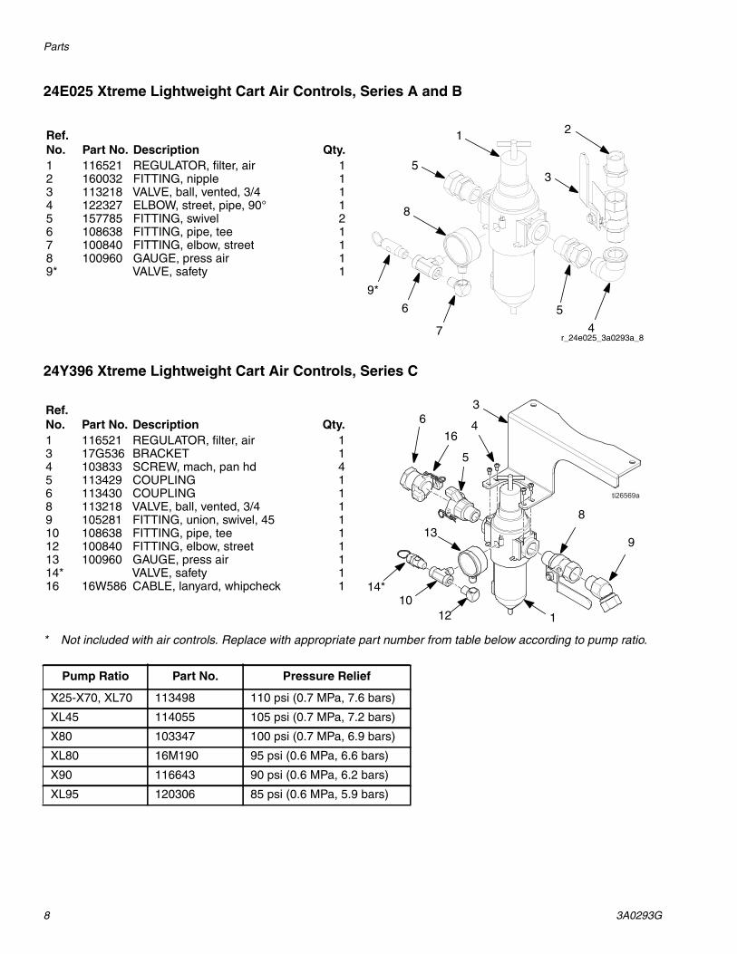
24E025 Xtreme Lightweight Cart Air Controls, Series A and B
24Y396 Xtreme Lightweight Cart Air Controls, Series C
* Not included with air controls. Replace with appropriate part number from table below according to pump ratio.
1 2
3
4
5
7
6
8
5
9*
Ref.No. Part No. Description Qty.1 116521 REGULATOR, filter, air 12 160032 FITTING, nipple 13 113218 VALVE, ball, vented, 3/4 14 122327 ELBOW, street, pipe, 90° 15 157785 FITTING, swivel 26 108638 FITTING, pipe, tee 17 100840 FITTING, elbow, street 18 100960 GAUGE, press air 19* VALVE, safety 1
r_24e025_3a0293a_8
Ref.No. Part No. Description Qty.1 116521 REGULATOR, filter, air 13 17G536 BRACKET 14 103833 SCREW, mach, pan hd 45 113429 COUPLING 16 113430 COUPLING 18 113218 VALVE, ball, vented, 3/4 19 105281 FITTING, union, swivel, 45 110 108638 FITTING, pipe, tee 112 100840 FITTING, elbow, street 113 100960 GAUGE, press air 114* VALVE, safety 116 16W586 CABLE, lanyard, whipcheck 1
6
14*10
12 1
4
3
8
16
5
913
Pump Ratio Part No. Pressure Relief
X25-X70, XL70 113498 110 psi (0.7 MPa, 7.6 bars)
XL45 114055 105 psi (0.7 MPa, 7.2 bars)
X80 103347 100 psi (0.7 MPa, 6.9 bars)
XL80 16M190 95 psi (0.6 MPa, 6.6 bars)
X90 116643 90 psi (0.6 MPa, 6.2 bars)
XL95 120306 85 psi (0.6 MPa, 5.9 bars)

Parts
3A0293G 9
24W593 and 24W040, For Xtreme XL Heavy Duty Cart or Wall Mount Packages
* Not included in 24W040. Install couplings (5) and (6) directly into regulator (1).
** Not included with air controls. Replace with appropriate part number from table below according to pump ratio.
244841 Lubricator Conversion Kit
Ref.No. Part No. Description Qty.1 17C498 REGULATOR, filter, air, 1 in. npt 12* 100467 ELBOW, street, pipe; wall mount
only1
3 17B747 BRACKET 14 103833 SCREW, mach, pan hd 45 127784 COUPLING, universal, 1 in. npt(m) 16 127785 COUPLING, universal, 1 in. npt(f) 17 158585 NIPPLE 18 113163 VALVE, ball, vented 19 127945 FITTING, swivel, 45°, 1 npt x 1
npsm1
10 108638 FITTING, pipe, tee 112 100840 FITTING, elbow, street 113 100960 GAUGE, pressure, air 114** VALVE, safety 116 16W586 CABLE, lanyard, whipcheck 1
8
9
7
2*
5
6
16
1
4
3
13
1210
14**
Pump Ratio Part No. Pressure Relief
X25-S70, XL70 113498 110 psi (0.7 MPa, 7.6 bars)
XL45 114055 105 psi (0.7 MPa, 7.2 bars)
X80 103347 100 psi (0.7 MPa, 6.9 bars)
XL80 16M190 95 psi (0.6 MPa, 6.6 bars)
X90 116643 90 psi (0.6 MPa, 6.2 bars)
XL95 120306 85 psi (0.6 MPa, 5.9 bars)
1
2c
* Elbow not used in all configurations.
Ref.No. Part No. Description Qty.1 C11034 LUBRICATOR, air 12 116522 AIR CONTROL, conversion kit
(includes 2a-2c)1
2a ADAPTER 12b PINS, retaining 22c O-RING 24* 100549 ELBOW, street, 90°, 3/4 npt (m x f) 1
r_24e025_3A0293_4a
2c
2b
4*
2a

Technical Data
10 3A0293G
Technical Data
NOTE: 17C498 is the same regulator as 116521except with 1 in. npt end fittings instead of 3/4 npt.
Air ControlsUS Metric
Maximum air input pressure 250 psi 1.7 MPa, 17.2 barGauge Port Size (Air Regulator) 1/4 npt(f)Air Filter Element 40 micron polypropylene screenMaximum operating temperature 122°F 50°C
Air Inlet SizeXtreme 3/4 npsm(f)Xtreme XL 1 in. npt(f)Air Outlet SizeXtreme 3/4 npt(f)Xtreme XL 1 in. npsm(f)
MODEL 116521 AIR REGULATOR FLOW CURVE
OU
TP
UT
PR
ES
SU
RE
(MP
a,b
ar)
AIR FLOW AT INLET PRESSURE OF100 PSI (0.7 MPa, BAR), 3/4 in. port,
and 40 micron element
50(1.120)
60
80(0.55, 5.5)
(0.41, 4.1)
40(0.28, 2.8)
20(0.14, 1.4)
100(2.240)
150(3.360)
200(4.480)
250(5.600)
Technical Data
3A0293G 11

All written and visual data contained in this document reflects the latest product information available at the time of publication.Graco reserves the right to make changes at any time without notice.
For patent information, see www.graco.com/patents.
Original instructions. This manual contains English. MM 3A0293
Graco Headquarters: MinneapolisInternational Offices: Belgium, China, Japan, Korea
GRACO INC. AND SUBSIDIARIES • P.O. BOX 1441 • MINNEAPOLIS MN 55440-1441 • USACopyright 2010, Graco Inc. All Graco manufacturing locations are registered to ISO 9001.
www.graco.comRevision G, January 2017
Graco Standard WarrantyGraco warrants all equipment referenced in this document which is manufactured by Graco and bearing its name to be free from defects inmaterial and workmanship on the date of sale to the original purchaser for use. With the exception of any special, extended, or limited warrantypublished by Graco, Graco will, for a period of twelve months from the date of sale, repair or replace any part of the equipment determined byGraco to be defective. This warranty applies only when the equipment is installed, operated and maintained in accordance with Graco’s writtenrecommendations.
This warranty does not cover, and Graco shall not be liable for general wear and tear, or any malfunction, damage or wear caused by faultyinstallation, misapplication, abrasion, corrosion, inadequate or improper maintenance, negligence, accident, tampering, or substitution ofnon-Graco component parts. Nor shall Graco be liable for malfunction, damage or wear caused by the incompatibility of Graco equipment withstructures, accessories, equipment or materials not supplied by Graco, or the improper design, manufacture, installation, operation ormaintenance of structures, accessories, equipment or materials not supplied by Graco.
This warranty is conditioned upon the prepaid return of the equipment claimed to be defective to an authorized Graco distributor for verification ofthe claimed defect. If the claimed defect is verified, Graco will repair or replace free of charge any defective parts. The equipment will be returnedto the original purchaser transportation prepaid. If inspection of the equipment does not disclose any defect in material or workmanship, repairs willbe made at a reasonable charge, which charges may include the costs of parts, labor, and transportation.
THIS WARRANTY IS EXCLUSIVE, AND IS IN LIEU OF ANY OTHER WARRANTIES, EXPRESS OR IMPLIED, INCLUDING BUT NOT LIMITEDTO WARRANTY OF MERCHANTABILITY OR WARRANTY OF FITNESS FOR A PARTICULAR PURPOSE.
Graco’s sole obligation and buyer’s sole remedy for any breach of warranty shall be as set forth above. The buyer agrees that no other remedy(including, but not limited to, incidental or consequential damages for lost profits, lost sales, injury to person or property, or any other incidental orconsequential loss) shall be available. Any action for breach of warranty must be brought within two (2) years of the date of sale.
GRACO MAKES NO WARRANTY, AND DISCLAIMS ALL IMPLIED WARRANTIES OF MERCHANTABILITY AND FITNESS FOR APARTICULAR PURPOSE, IN CONNECTION WITH ACCESSORIES, EQUIPMENT, MATERIALS OR COMPONENTS SOLD BUT NOTMANUFACTURED BY GRACO. These items sold, but not manufactured by Graco (such as electric motors, switches, hose, etc.), are subject tothe warranty, if any, of their manufacturer. Graco will provide purchaser with reasonable assistance in making any claim for breach of thesewarranties.
In no event will Graco be liable for indirect, incidental, special or consequential damages resulting from Graco supplying equipment hereunder, orthe furnishing, performance, or use of any products or other goods sold hereto, whether due to a breach of contract, breach of warranty, thenegligence of Graco, or otherwise.
FOR GRACO CANADA CUSTOMERSThe Parties acknowledge that they have required that the present document, as well as all documents, notices and legal proceedings entered into,given or instituted pursuant hereto or relating directly or indirectly hereto, be drawn up in English. Les parties reconnaissent avoir convenu que larédaction du présente document sera en Anglais, ainsi que tous documents, avis et procédures judiciaires exécutés, donnés ou intentés, à la suitede ou en rapport, directement ou indirectement, avec les procédures concernées.
Graco Information
For the latest information about Graco products, visit www.graco.com.
For patent information, see www.graco.com/patents.
TO PLACE AN ORDER, contact your Graco distributor or call to identify the nearest distributor.Phone: 612-623-6921 or Toll Free: 1-800-328-0211 Fax: 612-378-3505


![How to Use - Sonyhelpguide.sony.net/cam/1630/v1/en/print.pdf · How to Use Before use Model Information ... Parts and controls (front/top) [2] Parts and controls (LCD monitor) [3]](https://img.dokumen.tips/doc/110x75/5abaf0ef7f8b9a441d8c3dec/how-to-use-to-use-before-use-model-information-parts-and-controls-fronttop.jpg)