Embed Size (px)
Citation preview
9248 163 Street Surrey, BC V4N 3C9
604-637-2167 [email protected]
Page 18 of 33
3: in function keys, in second function keys.
3: in function keys, 72 in second function keys. Status block will be:
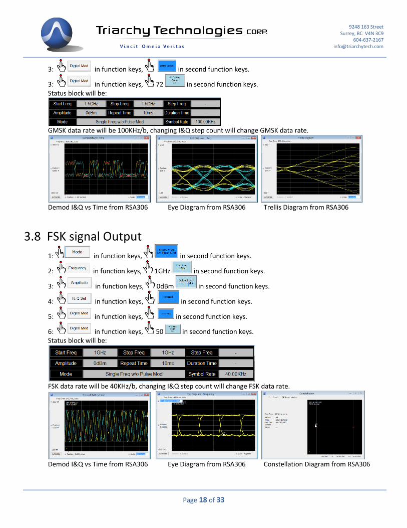
GMSK data rate will be 100KHz/b, changing I&Q step count will change GMSK data rate.
Demod I&Q vs Time from RSA306 Eye Diagram from RSA306 Trellis Diagram from RSA306 3.8 FSK signal Output
1: in function keys, in second function keys.
2: in function keys, 1GHz in second function keys.
3: in function keys, 0dBm in second function keys.
4: in function keys, in second function keys.
5: in function keys, in second function keys.
6: in function keys, 50 in second function keys. Status block will be:
FSK data rate will be 40KHz/b, changing I&Q step count will change FSK data rate.
Demod I&Q vs Time from RSA306 Eye Diagram from RSA306 Constellation Diagram from RSA306
9248 163 Street Surrey, BC V4N 3C9
604-637-2167 [email protected]
Page 19 of 33
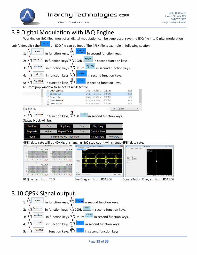
3.9 Digital Modulation with I&Q Engine Working on I&Q file,most of all digital modulation can be generated, save the I&Q file into Digital modulation
sub folder, click the , I&Q file can be input. The 4FSK file is example in following section.
1: in function keys, in second function keys.
2: in function keys, 1GHz in second function keys.
3: in function keys, 0dBm in second function keys.
4: in function keys, in second function keys.
5: in function keys, in second function keys. 6: From pop window to select IQ 4FSK.txt file.
7: in function keys, 50 in second function keys. Status block will be:
4FSK data rate will be 40KHz/b, changing I&Q step count will change 4FSK data rate.
I&Q pattern from TSG Eye Diagram from RSA306 Constellation Diagram from RSA306 3.10 QPSK Signal output
1: in function keys, in second function keys.
2: in function keys, 1GHz in second function keys.
3: in function keys, 0dBm in second function keys.
4: in function keys, in second function keys.
5: in function keys, in second function keys.
9248 163 Street Surrey, BC V4N 3C9
604-637-2167 [email protected]
Page 20 of 33
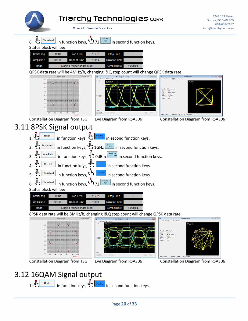
6: in function keys, 72 in second function keys. Status block will be:
QPSK data rate will be 4MHz/b, changing I&Q step count will change QPSK data rate.
Constellation Diagram from TSG Eye Diagram from RSA306 Constellation Diagram from RSA306 3.11 8PSK Signal output
1: in function keys, in second function keys.
2: in function keys, 1GHz in second function keys.
3: in function keys, 0dBm in second function keys.
4: in function keys, in second function keys.
5: in function keys, in second function keys.
6: in function keys, 72 in second function keys. Status block will be:
8PSK data rate will be 8MHz/b, changing I&Q step count will change QPSK data rate.
Constellation Diagram from TSG Eye Diagram from RSA306 Constellation Diagram from RSA306
3.12 16QAM Signal output
1: in function keys, in second function keys.
9248 163 Street Surrey, BC V4N 3C9
604-637-2167 [email protected]
Page 21 of 33
2: in function keys, 1GHz in second function keys.
3: in function keys, 0dBm in second function keys.
4: in function keys, in second function keys.
5: in function keys, in second function keys.
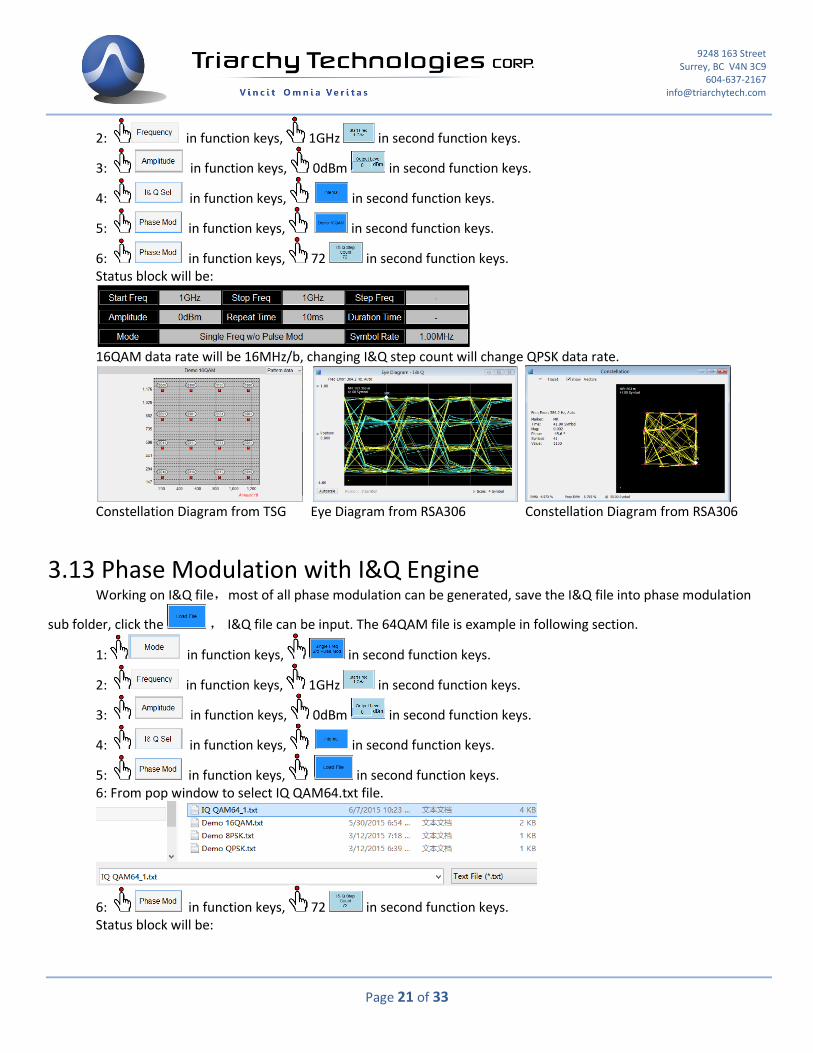
6: in function keys, 72 in second function keys. Status block will be:
16QAM data rate will be 16MHz/b, changing I&Q step count will change QPSK data rate.
Constellation Diagram from TSG Eye Diagram from RSA306 Constellation Diagram from RSA306 3.13 Phase Modulation with I&Q Engine
Working on I&Q file,most of all phase modulation can be generated, save the I&Q file into phase modulation
sub folder, click the , I&Q file can be input. The 64QAM file is example in following section.
1: in function keys, in second function keys.
2: in function keys, 1GHz in second function keys.
3: in function keys, 0dBm in second function keys.
4: in function keys, in second function keys.
5: in function keys, in second function keys. 6: From pop window to select IQ QAM64.txt file.
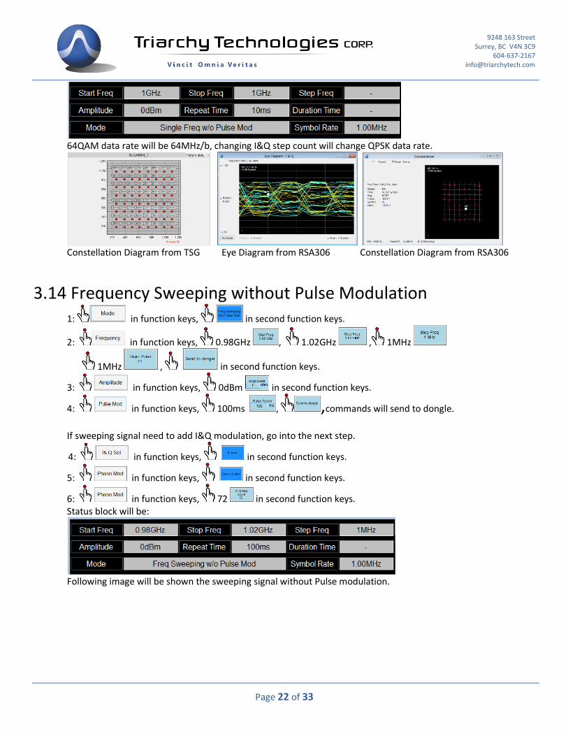
6: in function keys, 72 in second function keys. Status block will be:
9248 163 Street Surrey, BC V4N 3C9
604-637-2167 [email protected]
Page 22 of 33
64QAM data rate will be 64MHz/b, changing I&Q step count will change QPSK data rate.
Constellation Diagram from TSG Eye Diagram from RSA306 Constellation Diagram from RSA306 3.14 Frequency Sweeping without Pulse Modulation
1: in function keys, in second function keys.
2: in function keys, 0.98GHz , 1.02GHz , 1MHz
1MHz , in second function keys.
3: in function keys, 0dBm in second function keys.
4: in function keys, 100ms , ,commands will send to dongle.
If sweeping signal need to add I&Q modulation, go into the next step.
4: in function keys, in second function keys.
5: in function keys, in second function keys.
6: in function keys, 72 in second function keys. Status block will be:
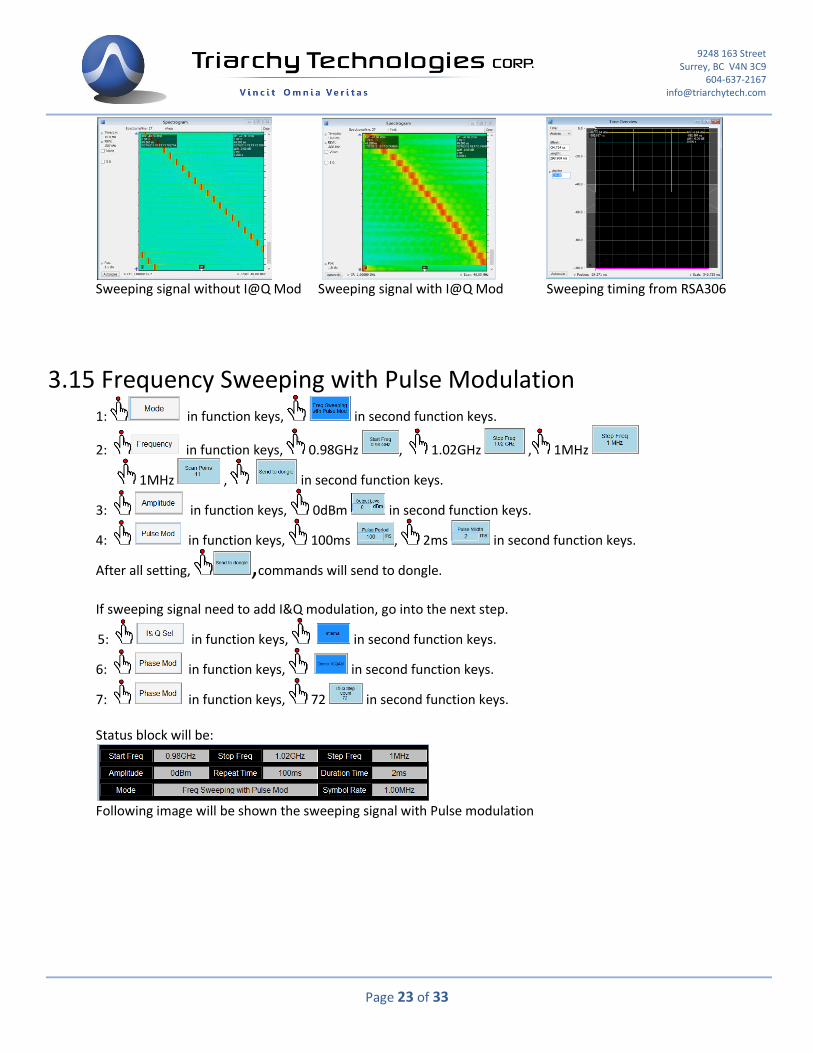
Following image will be shown the sweeping signal without Pulse modulation.
9248 163 Street Surrey, BC V4N 3C9
604-637-2167 [email protected]
Page 23 of 33
Sweeping signal without I@Q Mod Sweeping signal with I@Q Mod Sweeping timing from RSA306 3.15 Frequency Sweeping with Pulse Modulation
1: in function keys, in second function keys.
2: in function keys, 0.98GHz , 1.02GHz , 1MHz
1MHz , in second function keys.
3: in function keys, 0dBm in second function keys.
4: in function keys, 100ms , 2ms in second function keys.
After all setting, ,commands will send to dongle.
If sweeping signal need to add I&Q modulation, go into the next step.
5: in function keys, in second function keys.
6: in function keys, in second function keys.
7: in function keys, 72 in second function keys. Status block will be:
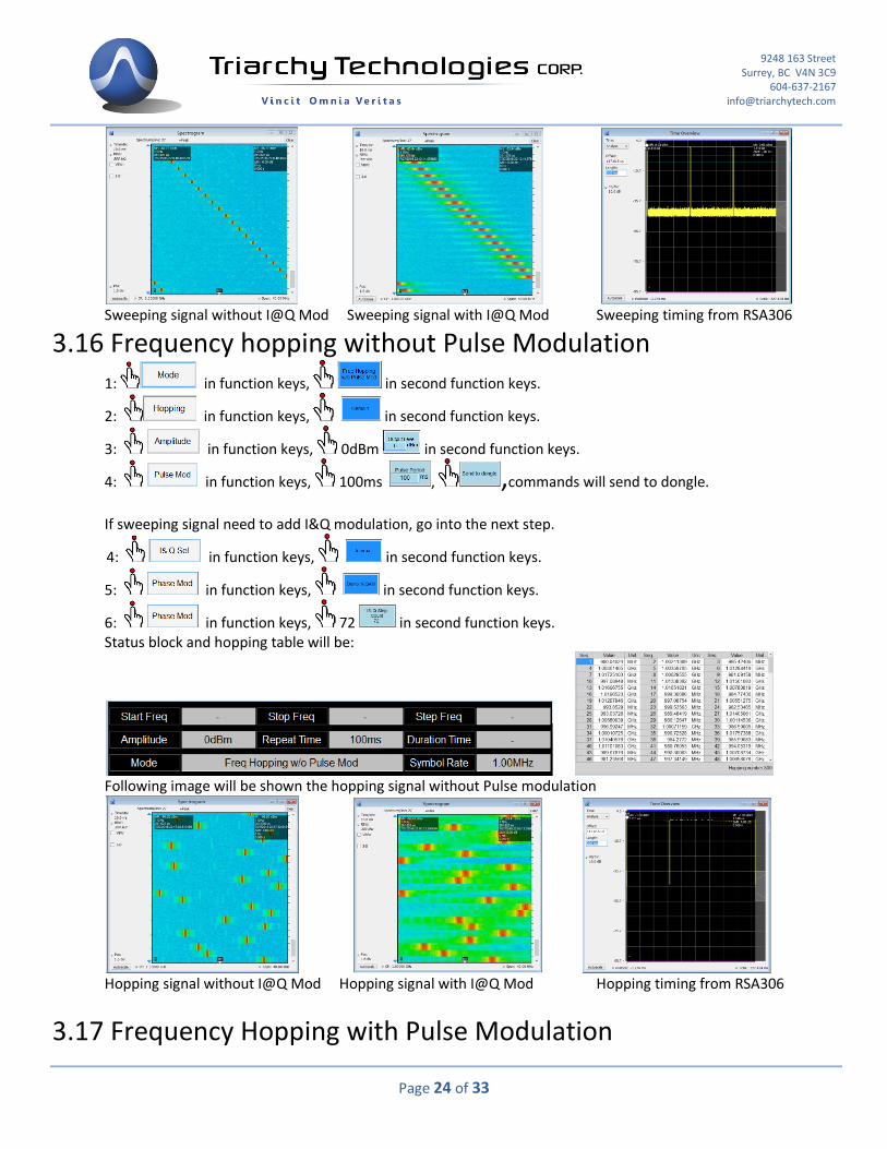
Following image will be shown the sweeping signal with Pulse modulation
9248 163 Street Surrey, BC V4N 3C9
604-637-2167 [email protected]
Page 24 of 33
Sweeping signal without I@Q Mod Sweeping signal with I@Q Mod Sweeping timing from RSA306 3.16 Frequency hopping without Pulse Modulation
1: in function keys, in second function keys.
2: in function keys, in second function keys.
3: in function keys, 0dBm in second function keys.
4: in function keys, 100ms , ,commands will send to dongle.
If sweeping signal need to add I&Q modulation, go into the next step.
4: in function keys, in second function keys.
5: in function keys, in second function keys.
6: in function keys, 72 in second function keys. Status block and hopping table will be:
Following image will be shown the hopping signal without Pulse modulation
Hopping signal without I@Q Mod Hopping signal with I@Q Mod Hopping timing from RSA306
3.17 Frequency Hopping with Pulse Modulation
9248 163 Street Surrey, BC V4N 3C9
604-637-2167 [email protected]
Page 25 of 33
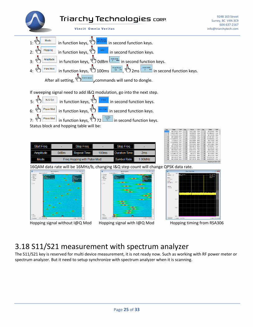
1: in function keys, in second function keys.
2: in function keys, in second function keys.
3: in function keys, 0dBm in second function keys.
4: in function keys, 100ms , 2ms in second function keys.
After all setting, ,commands will send to dongle.
If sweeping signal need to add I&Q modulation, go into the next step.
5: in function keys, in second function keys.
6: in function keys, in second function keys.
7: in function keys, 72 in second function keys. Status block and hopping table will be:
16QAM data rate will be 16MHz/b, changing I&Q step count will change QPSK data rate.
Hopping signal without I@Q Mod Hopping signal with I@Q Mod Hopping timing from RSA306
3.18 S11/S21 measurement with spectrum analyzer
The S11/S21 key is reserved for multi device measurement, it is not ready now. Such as working with RF power meter or spectrum analyzer. But it need to setup synchronize with spectrum analyzer when it is scanning.
9248 163 Street Surrey, BC V4N 3C9
604-637-2167 [email protected]
Page 26 of 33
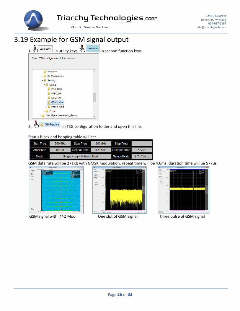
3.19 Example for GSM signal output
1: in utility keys, in second function keys.
2: in TSG configuration folder and open this file.
Status block and hopping table will be:
GSM data rate will be 271Kb with GMSK modulation, repeat time will be 4.6ms, duration time will be 577us.
GSM signal with I@Q Mod One slot of GSM signal three pulse of GSM signal

9248 163 Street Surrey, BC V4N 3C9
604-637-2167 [email protected]
Page 27 of 33
3.20 Pulse modulation signal output
The Pulse signal output port can generate pulse signal, when mode setup to xxx with pulse mod. The parameter of pulse
can be setup at pulse mod. , following will be pulse signal output measured by scope.
3.21 SIN/Triangle/Spiral waveform signal output
VSG6G1/VSG2G1/TSG4G1 also can output low frequency signal, using I&Q raw data file, I&Q port can output any kind of low frequency signal, the demo setting will be sin waveform, triangle waveform, and spiral waveform, output waveform will be shown at following:
You can output a lot different waveform by define I&Q raw data file, it is more like arbitrary signal generator. The frequency can be setup I*Q step count to fine turn. The total sampling length are also impact with output frequency. The frequency=72MHz/(step count*sampling length). 3.22 Clock selection
Internal clock reference will be 12MHz, and Main processor will be working at 72MHz, maximum the I&Q symbol rate will be 2.4MHz ( when I*Q step count set at 30). When clock select at internal, it is also the default setting, clock port will be output 12MHz reference clock. When clock select at external, it needs to input 10MHz reference clock at clock port, the clock level need to be larger than 5dBm. Internal clock reference will be 12MHz, and Main processor will be work at 72MHz, maximum the I&Q symbol rate will be 2.4MHz ( when I*Q step count set at 30). When clock select at internal, it is also default setting, clock port will output 12MHz reference clock. When clock select at external, it need input 10MHz reference clock at clock port, the clock level need to be larger than 5dBm.
9248 163 Street Surrey, BC V4N 3C9
604-637-2167 [email protected]
Page 28 of 33
3.23 I&Q Selection
I&Q port selection will have three choice: 1: None: it will turn off any I&Q modulation, only CW signal will be output. 2: Internal: internal I&Q waveform will connect to modulation IC. 3: External/Fast: External setup will need I&Q signal input from I&Q port, it can generate very fast modulation, the signal bandwidth can be setup to 500MHz. Fast setup will be reserved for high speed I&Q data generator option. It is an accessory of VSG6G1, it can generate up to 100MHz data rate modulation signal. 3.24 Hardcopy Operation
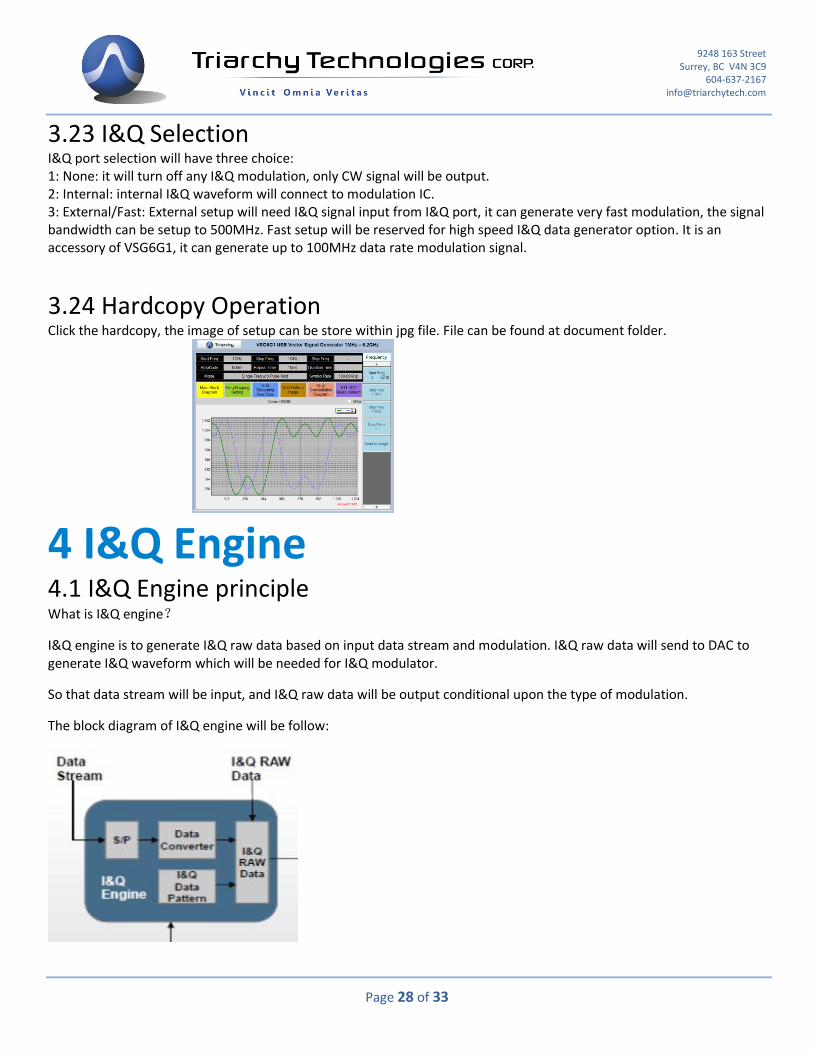
Click the hardcopy, the image of setup can be store within jpg file. File can be found at document folder.
4 I&Q Engine
4.1 I&Q Engine principle
What is I&Q engine?
I&Q engine is to generate I&Q raw data based on input data stream and modulation. I&Q raw data will send to DAC to generate I&Q waveform which will be needed for I&Q modulator.
So that data stream will be input, and I&Q raw data will be output conditional upon the type of modulation.
The block diagram of I&Q engine will be follow:
9248 163 Street Surrey, BC V4N 3C9
604-637-2167 [email protected]
Page 29 of 33
First, data stream will be go into S/P block, which is series to parallel section, most of modulation need this S/P section to setup I&Q mapping.
After S/P section, the parallel data may be need to do certain types of process, such as Gray code conversion, this section will be Data converter.
The parallel data will be mapping with I&Q data pattern to generate I&Q raw data. The mapping pattern is depend on the modulation, a lot of text book will discuss I&Q data pattern. Studying the data pattern can be generated a lot of different kind of modulation.
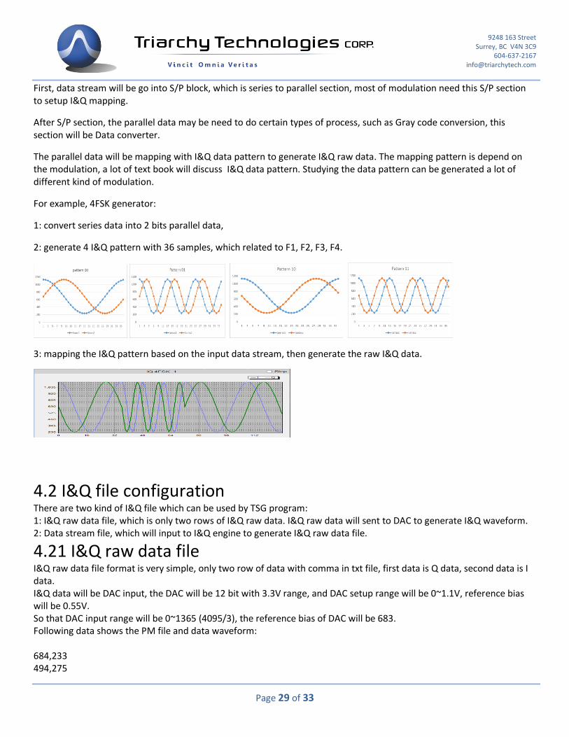
For example, 4FSK generator:
1: convert series data into 2 bits parallel data,
2: generate 4 I&Q pattern with 36 samples, which related to F1, F2, F3, F4.
3: mapping the I&Q pattern based on the input data stream, then generate the raw I&Q data.
4.2 I&Q file configuration
There are two kind of I&Q file which can be used by TSG program: 1: I&Q raw data file, which is only two rows of I&Q raw data. I&Q raw data will sent to DAC to generate I&Q waveform. 2: Data stream file, which will input to I&Q engine to generate I&Q raw data file. 4.21 I&Q raw data file
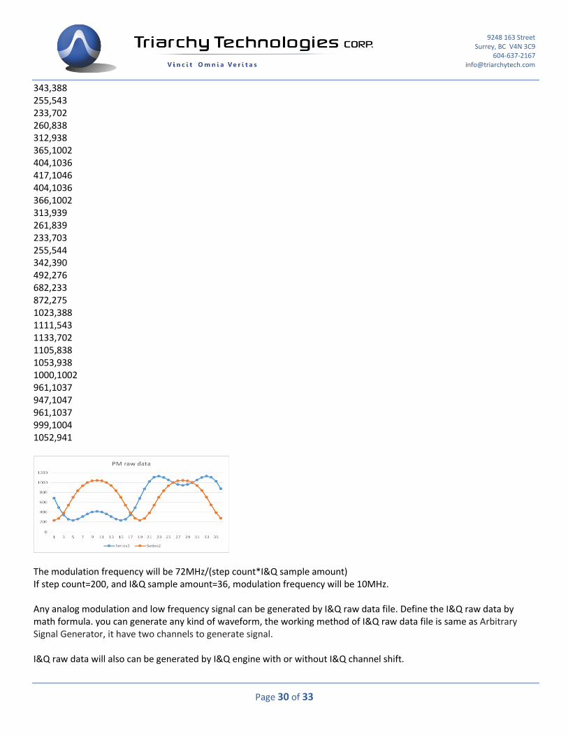
I&Q raw data file format is very simple, only two row of data with comma in txt file, first data is Q data, second data is I data. I&Q data will be DAC input, the DAC will be 12 bit with 3.3V range, and DAC setup range will be 0~1.1V, reference bias will be 0.55V. So that DAC input range will be 0~1365 (4095/3), the reference bias of DAC will be 683. Following data shows the PM file and data waveform: 684,233 494,275
9248 163 Street Surrey, BC V4N 3C9
604-637-2167 [email protected]
Page 30 of 33
343,388 255,543 233,702 260,838 312,938 365,1002 404,1036 417,1046 404,1036 366,1002 313,939 261,839 233,703 255,544 342,390 492,276 682,233 872,275 1023,388 1111,543 1133,702 1105,838 1053,938 1000,1002 961,1037 947,1047 961,1037 999,1004 1052,941
The modulation frequency will be 72MHz/(step count*I&Q sample amount) If step count=200, and I&Q sample amount=36, modulation frequency will be 10MHz. Any analog modulation and low frequency signal can be generated by I&Q raw data file. Define the I&Q raw data by math formula. you can generate any kind of waveform, the working method of I&Q raw data file is same as Arbitrary Signal Generator, it have two channels to generate signal. I&Q raw data will also can be generated by I&Q engine with or without I&Q channel shift.

9248 163 Street Surrey, BC V4N 3C9
604-637-2167 [email protected]
Page 31 of 33
Click the system in the utility keys, you will find I&Q AMP shift and I&Q Phase shift in the second function keys.
The default value for shift is 0. If you use default value, I&Q raw data file generated from I&Q engine will be not shift.
For example, input data stream file of into the I&Q engine, output will be raw data file . The constellation image will be:
If change I&Q AMP shift to 5 and I&Q Phase shift to 10, output will be raw data file . The constellation image will be:
The I&Q amp and phase shift will be used for compensation of I&Q unbalance. When VSG6G1 is working on the band 2, I&Q channel will generate unbalance due to the Mixer stage. You have to use function of I&Q amp and phase shift to improve the EVM parameter. I&Q AMP shift will be amplitude shift of I&Q channel with unit in percentage. I&Q Phase shift will be phase shift of I&Q channel with unit in degree. 4.22 Data stream file
Data stream file will be include input data, I&Q pattern and some settings. When you open the data stream file, you will find four section: 1: Data input 2: S/P setting 3: converter setting 4: I&Q pattern data the file format will be shown at following:
9248 163 Street Surrey, BC V4N 3C9
604-637-2167 [email protected]
Page 32 of 33
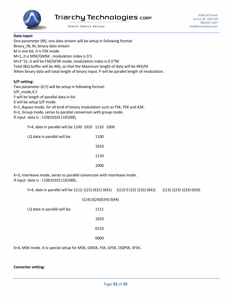
Data input: One parameter (M), one data stream will be setup in following format: Binary_IN, M, binary data stream M is one bit, it is FSK mode. M=1, it is MSK/GMSK , modulation index is 0.5 M=2~15, it will be FSK/GFSK mode, modulation index is 0.5*M Total I&Q buffer will be 4Kb, so that the Maximum length of data will be 4Kb/M When binary data will total length of binary input. P will be parallel length of modulation. S/P setting: Two parameter (X,Y) will be setup in following format: S/P_mode,X,Y Y will be length of parallel data in bit. X will be setup S/P mode. X=1, Bypass mode, for all kind of binary modulation such as FSK, PSK and ASK. X=2, Group mode, series to parallel conversion with group mode. If input data is : 1100101011101000,
Y=4, date in parallel will be 1100 1010 1110 1000
I,Q data in parallel will be: 1100
1010
1110
1000
X=3, interleave mode, series to parallel conversion with interleave mode. If input data is : 1100101011101000,
Y=4, date in parallel will be 1(11) 1(21) 0(31) 0(41) 1(12) 0 (22) 1(32) 0(42) 1(13) 1(23) 1(33) 0(43)
1(14) 0(24)0(34) 0(44)
I,Q data in parallel will be: 1111
1010
0110
0000
X=4, MSK mode. It is special setup for MSK, GMSK, FSK, GFSK, OQPSK, SFSK..
Converter setting:
9248 163 Street Surrey, BC V4N 3C9
604-637-2167 [email protected]
Page 33 of 33
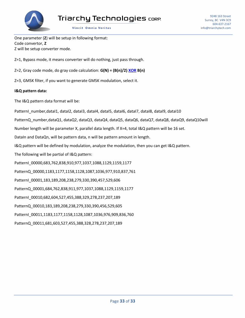
One parameter (Z) will be setup in following format: Code convertor, Z Z will be setup converter mode. Z=1, Bypass mode, it means converter will do nothing, just pass through. Z=2, Gray code mode, do gray code calculation: G(N) = (B(n)/2) XOR B(n)
Z=3, GMSK filter, if you want to generate GMSK modulation, select it.
I&Q pattern data:
The I&Q pattern data format will be:
PatternI_number,dataI1, dataI2, dataI3, dataI4, dataI5, dataI6, dataI7, dataI8, dataI9, dataI10
PatternQ_number,dataQ1, dataQ2, dataQ3, dataQ4, dataQ5, dataQ6, dataQ7, dataQ8, dataQ9, dataQ10will
Number length will be parameter X, parallel data length. If X=4, total I&Q pattern will be 16 set.
DataIn and DataQn, will be pattern data, n will be pattern amount in length.
I&Q pattern will be defined by modulation, analyze the modulation, then you can get I&Q pattern.
The following will be partial of I&Q pattern:
PatternI_00000,683,762,838,910,977,1037,1088,1129,1159,1177
PatternQ_00000,1183,1177,1158,1128,1087,1036,977,910,837,761
PatternI_00001,183,189,208,238,279,330,390,457,529,606
PatternQ_00001,684,762,838,911,977,1037,1088,1129,1159,1177
PatternI_00010,682,604,527,455,388,329,278,237,207,189
PatternQ_00010,183,189,208,238,279,330,390,456,529,605
PatternI_00011,1183,1177,1158,1128,1087,1036,976,909,836,760
PatternQ_00011,681,603,527,455,388,328,278,237,207,189