Embed Size (px)
Citation preview

3.7 Find the time function corresponding to each of the following Laplace transforms using partial-fraction expansions:
/ ' T""" / ' ?

Problems 171 I
v(c) F(s) == 3s+2 s2+4s+20
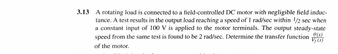
3.13 A rotating load is connected to a field-controlled DC motor with negligible field inductance. A test results in the output load reaching a speed of 1 rad/sec within l/2 sec when a constant input of 100 V is applied to the motor terminals. The output steady-state
speed from the same test is found to be 2 rad/sec. Determine the transfer function ;.rJ of the motor.

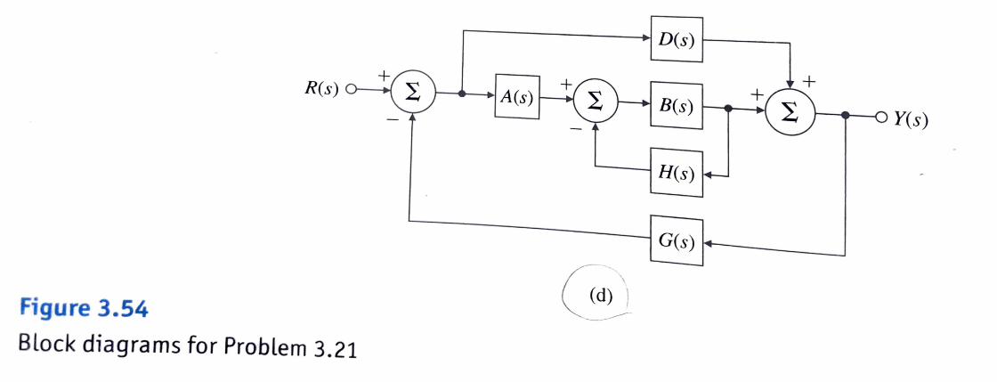
3.21 Find the transfer functions for the block diagrams in Fig. 3 .54, using the ideas of block diagram simplification. The special structure in Fig. 3 .54(b) is called the "observer canonical form" and will be discussed in Chapter 7.
D(s) r----__,
R(s) A(s) ,..__.. B(s) r--.~
Y(s)
H(s)
Figure 3.54 G Block diagrams for Problem 3.21

Figure 3.57
Unity feedback system for Problem 3.24
3.24 For the unity feedback system shown in Fig. 3.57, specify the gain K of the proportional controller so that the output y(t) has an overshoot of no more than 10% in response to a unit step.
R(s) 1 s(s + 2)
Y(s)
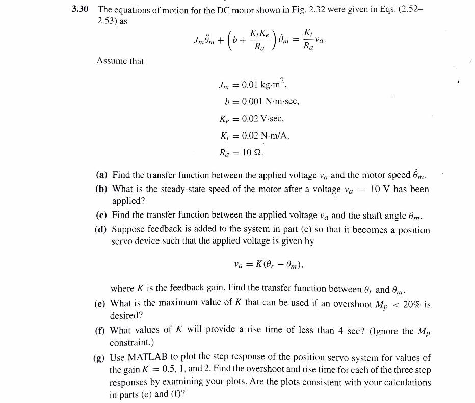
3.30 The equations of motion for the DC motor shown in Fig. 2.32 were given in Eqs. (2.52-2.53) as
Assume that
2 lm = 0.01 kg-m ,
b = 0.001 N-m-sec,
Ke= 0.02 V-sec,
Kt= 0.02 N-rn/A,
Ra= 10 Q.
(a) Find the transfer function between the applied voltage Va and the motor speed 0m.
(b) What is the steady-state speed of the motor after a voltage Va = 10 V has been applied? ·
(c) Find the transfer function between the applied voltage Va and the shaft angle 0m.
(d) Suppose feedback is added to the system in part (c) so that it becomes a position servo device such that the applied voltage is given by
Va == K(0r - 0,n),
where K is the feedback gain. Find the transfer function between 0r and 0m.
(e) What is the maximum value of K that can be used if an overshoot Mp < 20% is
desired?
(f) What values of K will provide a rise time of less than 4 sec? (Ignore the Mp constraint.)
(g) Use MATLAB to plot the step response of the position servo system for values of the gain K == 0.5, 1, and 2. Find the overshoot and rise time for each of the three step responses by examining your plots. Are the plots consistent with your calculations in parts ( e) and (f)?

EXAMPLE 2.13
Figure 2.32 DC motor: (a) electric circuit of the armature; (b) free-body diagram of the rotor
are correct.
Modeling a DC Motor in . ·t shown
F I tric c1rcu1 . t b. rnd the equations for a DC motor with the equivalent e ec. • coefficien
F 2 32 · s fnction the ig. · (a). Assume that the rotor has inertia lm and viscou b) defines
S I · · Fg 2.32( ' • · on of 0 uhon. The free-body diagram for the rotor, shown ID
1 · · APP11catl
· · · . T d b0rn· poSitive direction and shows the two applied torques, an Newton's laws yields (2.52)
] 1110111 + b0111 = K,ia- the electrical A l . f It ge shows
na ysis of the electric circuit, including the back em vo a ' · equation to be (2.53)
di · la_!!_+ Raia= Va - Ke0m-
. dt fi function for the Withs substituted for d/dt in Eqs. (2.52) and (2.53), the trans er
motor is readily found to be
0 111 (s) K, (2.54)
Va(s) - s[(J111 s + b)(las +Ra)+ K,Ke]
In many cases the relative effect of the inductance is negligible compared with the mechanjcal motion and can be neglected in Eq. (2.53). If so, we can combine Eqs. (2.52) and (2.53) into one equation to get
+
e = K0 e m
(a)
T
\
I (
j I
m
(2.55)

2.3 Models of Electromechanical Systems 67
From Eq. (2.55) it is clear that in this case the effect of the back emf is indistinguishable from the friction, and the transfer function is
where
J ms2 + ( b + K~:e ) s
K - ' s(rs + 1)
Kt K==----
bRa + KtKe'
Ralm r == -----
bRa + KtKe
(2.56)
(2.57)
(2.58)
(2.59)
In many cases, a transfer function between the motor input and the output speed (w == 0m) is required. In such cases, the transfer function would be
Q(s) 8m(s) K --==s--
Va(s) Va(s) TS+ l (2.60)