Embed Size (px)
Citation preview

TECHNICAL PAPER
ADVANCES IN GAS TURBINE TECHNOLOGY
Author: Cdr AM Jaffar Sirajuddin, Trials Officer, GTTT(Mbi)
Synopsis. This paper aims at bringing out the advancements made in Gas
Turbine technology in the field of GT manufacturing over the last few decades which
have lead to increased efficiency, reduced SFC and lower emissions. Considering
the fact that Gas Turbines are the mainstay of Indian Navy, it is essential to absorb
the latest technology available in the field to enable selection of justifiable &
sustainable propulsion/power generation machinery, incorporating latest
advancement/developments, in the years to come.
1. Introduction. Gas Turbines, in today’s world, are an inseparable part of
modern life where these durable machines are being utilised in the field of power
generation to air transport and shipping. From being the most compact way of
delivering power, at the time of their invention, Gas Turbines have evolved into
engineering marvels due to use of advanced metallurgy, computational fluid
dynamics, heat transfer, additive technology etc. Some of the technologies, which
have enabled these machines become more efficient by converting 60% of heat
energy into useful work (combined cycles), are discussed in this paper as these are
considered most suitable for Naval requirements.
2. Performance Improvement. Gas Turbines can be described as simple
machines with a compressor, to compress the working medium, a combustor, to add
heat energy into the working medium and a turbine, to convert the heat energy to
work for driving the compressor and for producing useful work. Performance of the
GT depends on the efficiency of the individual components and their performance.
3. The primary parameters/ components that contribute to increasing the
efficiency of the heat cycle are the compressor pressure ratio and the turbine inlet
temperature. Efficiency and performance of a Gas Turbine depends on the pressure
ratio which can be obtained in the compressor and the maximum Turbine Inlet
Temperature (TIT) which the turbine can withstand without experiencing Creep. The
effect of these parameters is briefly described in the succeeding paragraphs.

4. Pressure Ratio. Dependence of thermal efficiency of the Gas Turbine on
the pressure ratio obtained from the compressor is shown in the figure 1 below. It is
evident from the graph, that any increase in pressure ratio will improve the
performance and the efficiency of the Gas Turbine. It may be noted from the graph
that the thermal efficiency reaches above 60% as the pressure ratio is increased to
40:1.
Figure 1 – Dependence of Thermal Efficiency on Pressure Ratio
5. Turbine Inlet Temperature. Similarly, Turbine Inlet Temperature (TIT),
also play a major role in determining the performance/efficiency of the Gas Turbine.
As TIT approaches 2000K from 1000K, the thermal efficiency peaks to 55% from
50% as shown in figure 2 below.
Figure 2 – Dependence of Thermal Efficiency on TIT
6. Traditional Methods of Improving the Thermal Efficiency of GT Cycle.
In order to improve the efficiency of gas turbine power plants, one of the
following three methods are used.
(a) Gas Turbine cycle with Regeneration. The temperature at the
exhaust of the gas turbine is higher than the temperature of the air at the exit
of the compressor. In order to utilize the heat energy of the exhaust of the

turbine, which is a waste to the atmosphere, the compressed air is heated in a
heat exchanger called regenerator. In a counter flow heat exchanger, it is
theoretically possible to heat the air discharged by the compressor reversibly
to the temperature of the exhaust leaving the turbine and to cool the turbine
exhaust gases equal to the temperature of the discharge of the compressor
air.
(b) Gas Turbine cycle with Reheating. Turbine output can be
increased by reheating of the gas during expansion in two or stages. In
between the turbine stages, an additional combustors or reheaters are added
in order to heat the gases.
(c) Gas Turbine cycle with Intercooling. As it is known that the majority
of the power generated by the turbine is utilized for running compressor, it is
important to reduce the compressor power consumption. This can be
achieved by compressing the air in two or more number of stages by providing
an intercooler in between the stages such that law of compression
approaches to isothermal compression.
Figure 3 – Braton Cycle with Intercooling, Reheat and Regeneration
7. Why improve Manufacturing Process & not the GT Cycle. However,
utilising the above methods comes with a penalty of bulkiness of the Gas Turbine
which is not a viable option onboard warship. So researchers around the world have
made efforts in improving performance of the simple cycle Gas Turbine with the
power to weight ratio advantage offered by them in mind. This paper aims at bringing
the technological advancements being made in the field of design and manufacturing
of the Gas Turbines. The paper discusses improvements in Compressor Design

using CFD, increasing TIT by using Investment Casting & development of Single
Crystal Turbine Blades, using Additive Manufacturing processes, application of
advanced Thermal Barrier Coatings, employing Ceramic Matrix Composites for
Blade manufacture & using advanced Blade Cooling Technologies.
8. Computational Fluid Dynamics in Compressor Design. Computational
Fluid Dynamics has vastly changed the design of compressors and fluid flow,
thereby increasing the compressor efficiency. 3D design modelling using advanced
software has in some cases increased pressure ratios upto 30:1. The higher
pressure ratio reduces thermal loads from the higher firing temperature of this design
while keeping exhaust temperatures optimal for combined cycle application.
Compressor efficiency is enhanced by better stationary and rotating blade geometry
made possible by the three-dimensional computational fluid dynamic codes.
9. Better aerofoil shapes by the use of CFD design software both in rotating and
stationary blades has improved blade design helping the industry in trimming the
stages of the compressor and also reducing the number of blades in each stage
without compromising on the performance and mass flow. Notable instances in
improved compressor design include Westinghouse and its technology alliance
partners Rolls-Royce, Mitsubishi Heavy Industries and FiatAvio bumped the 501G`s
mass flow 25 percent over the 501F by increasing the mean diameter of the stages
and incorporating several advancements to individual components. The 501G`s
compressor, for example, has 17 stages, one more than the 501F, and provides an
increased pressure ratio of 19.2:1.
10. In another case, to achieve a similar pressure ratio of 16:1, Siemens was able
to eliminate two compressor stages (from 17 to 15) and trim cooling flow
requirements by using the CFD codes. With GE`s MS6001FA, designers were able
to increase inlet compressor flow by 40 percent over its previous design (MS6001B).
The blades in the first two rows of the unit`s 18-stage compressor feature a
transonic, tailored airfoil shape that is neither double circular arc nor NACA-65 in
form. The blades incorporate an advanced high-bypass ratio aircraft engine design
that minimizes shock losses at operating speeds.
Figure 4 – Flow Analysis Using CFD
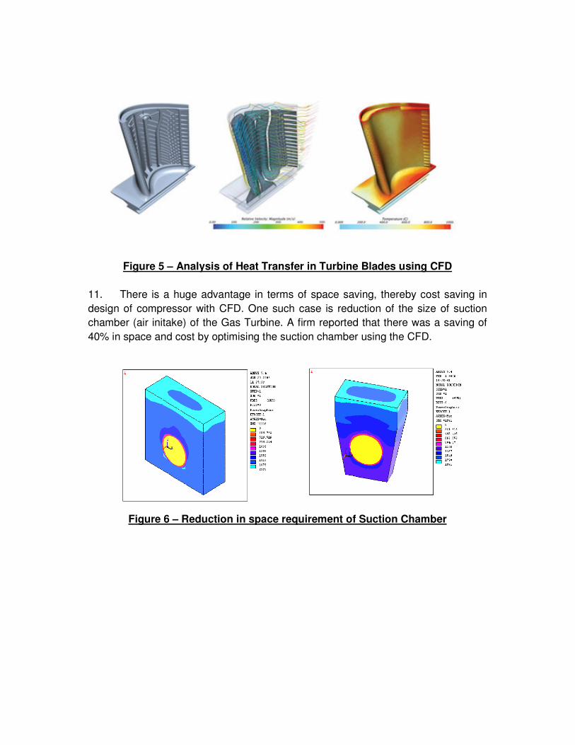
Figure 5 – Analysis of Heat Transfer in Turbine Blades using CFD
11. There is a huge advantage in terms of space saving, thereby cost saving in
design of compressor with CFD. One such case is reduction of the size of suction
chamber (air initake) of the Gas Turbine. A firm reported that there was a saving of
40% in space and cost by optimising the suction chamber using the CFD.
Figure 6 – Reduction in space requirement of Suction Chamber

12. Increasing Turbine Inlet Temperature. This is the single most important
factor which is restricting improvement of the performance of the Gas Turbines which
in turn is a function of the metallurgy being used for turbine blades. TIT has
increased from 740 K during the advent of Gas Turbine to 1400-1600 K today. Some
manufacturers have also achieved 1800 K and constant efforts are made in this field.
Key developments which are enabling engineers across the world to improve the TIT
are use of thermal barrier coating, blade cooling techniques, use of single crystal
blades and very recently Additive Manufacturing.
13. Single Crystal Turbine Blades. Normally, metals are composed of
many crystals – ordered structures of atoms arranged in a regular lattice, which form
naturally as the metal cools from a molten state. These crystals are typically of the
order of tens of microns in size, positioned in many orientations. At high
temperatures and under strain, the crystals can slide against each other, and
impurities can diffuse along the boundaries between the grains. This is known as
creep, and it badly affected early turbine blades, which were forged from steel and
later nickel bars.
14. Casting single crystals, with no grain boundaries reduced creep largely due to
non-availability of grain boundaries. It is a highly complex process with internal
cooling channels already in place. The lack of these grain boundaries inhibits creep
from occurring in this way. Creep will still occur in single crystal turbine blades but
due to different mechanisms that occur at higher temperatures. The single crystal
turbine blade does not have grain boundaries along directions of axial stress which
crystalline turbine blades. Single crystal turbine blades have the mechanical
advantage of being able to operate at a much higher temperature than crystalline
turbine blades. The turbine blades are able to operate at these high temperatures
due to the single crystal structure and the composition of the nickel based
superalloy.
Figure 7 – Single Crystal Blade Grain Structure

15. Blade Cooling Technology. Cooling of turbine blades can be achieved
by air or liquid cooling. Air cooling allows the discharged air into main flow without
any problem. Quantity of air required for this purpose is 1–3% of main flow and blade
temperature can be reduced by 200–300 °C. There are many techniques of cooling
used in gas turbine blades, convection cooling, film cooling, transpiration cooling,
effusion cooling, pin fin cooling etc. which fall under the categories of internal and
external cooling. While all methods have their differences, they all work by using
cooling air (often bled from the compressor) to remove heat from the turbine blades.
Figure 8 – First Stage Guide Vane with Drilled Holes for Cooling
16. Jet Impingement Cooling. Jet impinging on the inner surfaces of the
airfoil through tiny holes in the impingement insert is a common, highly efficient
cooling technique for first-stage vanes. Impingement cooling is very effective
because the cooling air can be delivered to impinge on the hot region. Jet
impingement cooling can be used only in the leading-edge of the rotor blade, due to
structure constraints on the rotor blade under high speed rotation and high
centrifugal loads.
Figure 9 – Jet Impingement Cooling Technique

17. Additive Manufacturing. Additive manufacturing uses computer-
aided-design (CAD) software or 3D object scanners to direct hardware to deposit
material, layer upon layer, in precise geometric shapes. As its name implies, additive
manufacturing adds material to create an object. By contrast, when you create an
object by traditional means, it is often necessary to remove material through milling,
machining, carving, shaping or other means. Although the terms "3D printing" and
"rapid prototyping" are casually used to discuss additive manufacturing, each
process is actually a subset of additive manufacturing. Below figure depicts some of
the components manufactured using Additive Manufacturing Technology.
Figure 10 – Components manufacturing using Additive Manufacturing
Technique
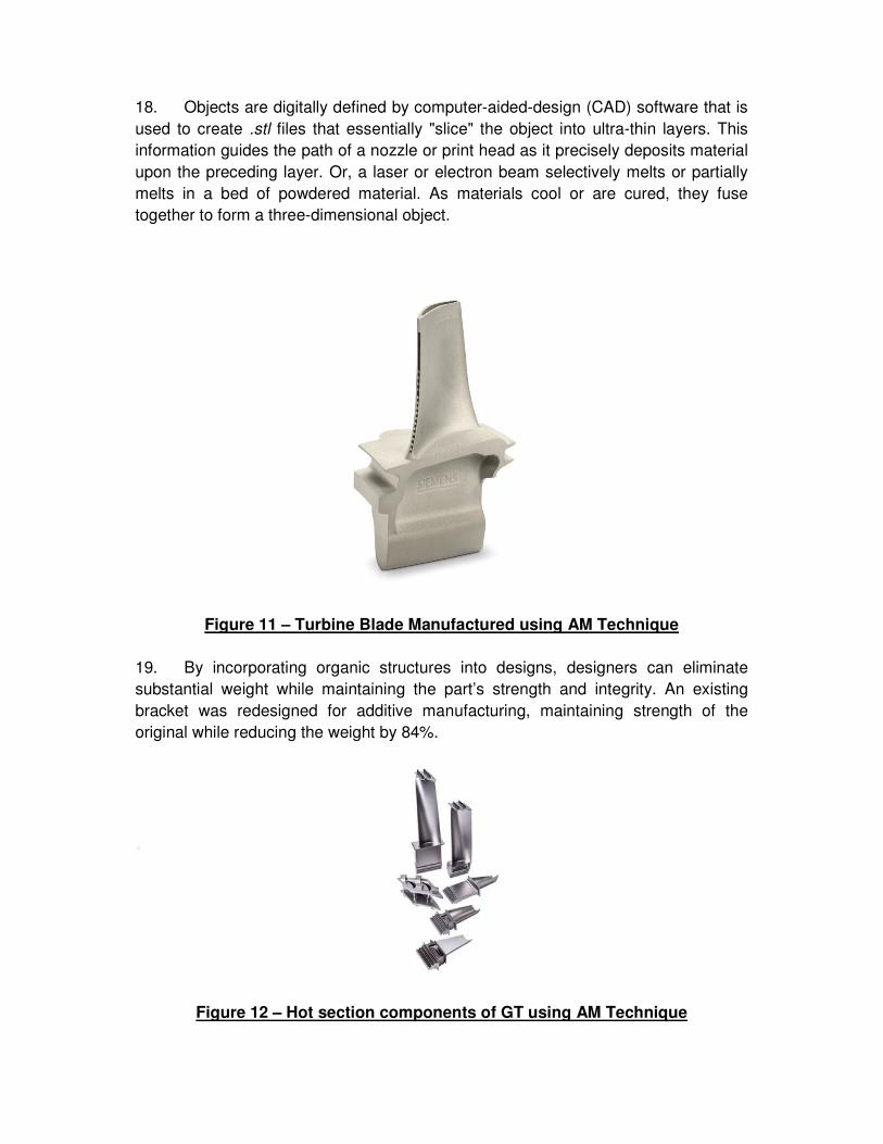
18. Objects are digitally defined by computer-aided-design (CAD) software that is
used to create .stl files that essentially "slice" the object into ultra-thin layers. This
information guides the path of a nozzle or print head as it precisely deposits material
upon the preceding layer. Or, a laser or electron beam selectively melts or partially
melts in a bed of powdered material. As materials cool or are cured, they fuse
together to form a three-dimensional object.
Figure 11 – Turbine Blade Manufactured using AM Technique
19. By incorporating organic structures into designs, designers can eliminate
substantial weight while maintaining the part’s strength and integrity. An existing
bracket was redesigned for additive manufacturing, maintaining strength of the
original while reducing the weight by 84%.
Figure 12 – Hot section components of GT using AM Technique

20. Thermal Barrier Coating. These 100 µm to 2 mm coatings serve to insulate
components from large and prolonged heat loads by utilizing thermally insulating
materials which can sustain an appreciable temperature difference between the
load-bearing alloys and the coating surface. Thermal barrier coatings typically
consist of four layers: the metal substrate, metallic bond coat, thermally-grown oxide
(TGO), and ceramic topcoat.
Figure 12 – Thermal Barrier Coating
21. The use of TBCs (100 to 500 µm in thickness), along with internal cooling of
the underlying superalloy component, provide major reductions in the surface
temperature (100° to 300°C) of the superalloy. This has enabled modern gas-turbine
engines to operate at gas temperatures well above the melting temperature of the
superalloy (∼1300°C), thereby improving engine efficiency and performance.
Figure 13 – TBC of a Turbine Blade

22. Ceramic Matrix Composites. Ceramic matrix composites (CMCs) are a
subgroup of composite materials as well as a subgroup of ceramics. They consist of
ceramic fibres embedded in a ceramic matrix. CMCs are coming on strong for all gas
turbines and this will change the way the hot parts of gas are made. The use of
CMCs in gas turbines permit higher turbine inlet temperatures, which improves
turbine efficiency. Because of the complex shape of stator vanes and turbine blades,
the development was first focused on the combustion chamber. In the US, a
combustor made of SiC/SiC with a special SiC fiber of enhanced high-temperature
stability was successfully tested for 15,000 hours.
Figure 14 – CMC Turbine Blades
23. Efforts are being made to manufacture parts by powdering Titanium Aluminide
(TiAl) and then through Additive Manufacturing technique. Parts could thus be made
that could not be made any other way. Advanced new fuel nozzles for GE’s new fan
jets are now being made this way by computer programs. The CMC blading being
much lighter (one third of the conventional blade) in weight makes it possible for the
gas turbine disks and bearings to be reduced in size and weight. The fir tree
connection of the blades to the disks can be simplified and less costly to
manufacture.
24. Conclusion. Efficiency of GTs being used in the IN is in the range of 35-38%
for M/s Zorya make GTs and is 38% for M/s GE make GTs. With advanced
technologies, it is not far off before the efficiency of the aero /industrial Gas Turbines
crossing the 40% mark. Therefore, it is imperative to induct GTs in future with some
of the technologies in the future. In addition, these technology will enable building
Power Generation equipment with much higher capacity which occupies less space.

25. References.
Advances in Gas Turbine Technology, Edited by Ernesto Bernini and published by
INTECH WEB.ORG
Additive Manufacturing of Aerospace Propulsion Components by Dr. Ajay Misra,
Dr. Joe Grady and Robert Carter in NASA Glenn Research Center, Cleveland, OH.
Analysis of the Temperature Distribution in GT Blade Cooled by Compressed Air by
Hussain H. Al-Kayiem and Amir H. Ghanizadeh.
CMCs will revolutionize aero and land-based gas turbines by TMI Staff &
contributors.
Ceramic matrix composite from Wikipedia, the free encyclopedia. Gas turbine technology is swiftly evolving as manufacturers introduce aero-derived
advances in the pursuit of more power by Steven E. Kuehn, Senior Editor.
Jewel in the crown: Rolls-Royce’s single-crystal turbine blade casting foundry by Stuart Nathan.
Recent Studies in Blade Cooling by Je-Chin Han for Taylor & Francis Group.
Space Age Ceramics are Aviation’s New Cup of Tea by Tomas Kellner.
Overview of a Gas Turbine and the different methods to improve Thermal Efficiency
by Gubbale Sesha Saikrishna, Mallavolu Sai Nithish and Nekkanti Raviteja.
The Cooling of Turbine Blades by Zhou Qin-sheng and Wang Feng.
The Development of Single Crystal Superalloy Turbine Blades by M Gell, D N Duhl and A F Giamei. Thermal barrier coating from Wikipedia, the free encyclopedia. Thermal Barrier Coatings for Gas-Turbine Engine Applications by Nitin P. Padture,
Maurice Gell and Eric H. Jordan.