Embed Size (px)
Citation preview
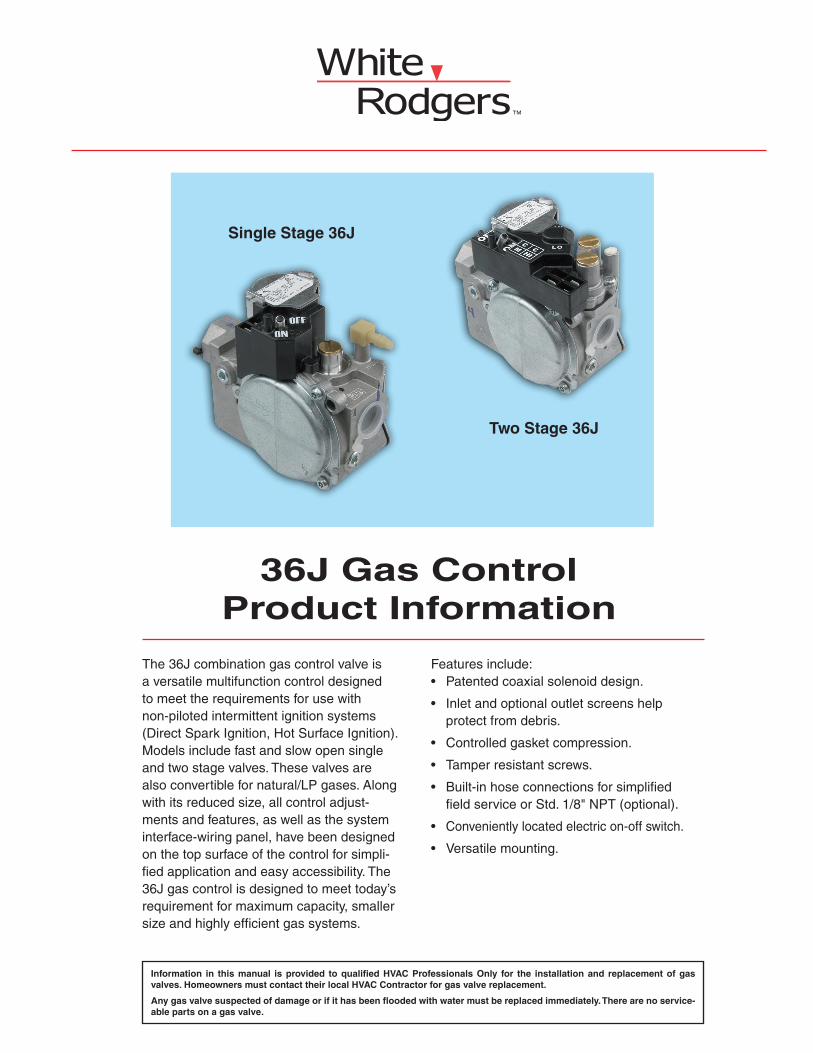
36J Gas ControlProduct Information
Features include: • Patentedcoaxialsolenoiddesign.
•Inletandoptionaloutletscreenshelpprotectfromdebris.
• Controlledgasketcompression.
•Tamperresistantscrews.
•Built-inhoseconnectionsforsimplified fieldserviceorStd.1/8"NPT(optional).
•Convenientlylocatedelectricon-offswitch.
•Versatilemounting.
The36Jcombinationgascontrolvalveisaversatilemultifunctioncontroldesignedtomeettherequirementsforusewithnon-pilotedintermittentignitionsystems(DirectSparkIgnition,HotSurfaceIgnition).Modelsincludefastandslowopensingleandtwostagevalves.Thesevalvesarealsoconvertiblefornatural/LPgases.Alongwithitsreducedsize,allcontroladjust-mentsandfeatures,aswellasthesysteminterface-wiringpanel,havebeendesignedonthetopsurfaceofthecontrolforsimpli-fiedapplicationandeasyaccessibility.The36Jgascontrolisdesignedtomeettoday’srequirementformaximumcapacity,smallersizeandhighlyefficientgassystems.
Single Stage 36J
Two Stage 36J
Information in this manual is provided to qualified HVAC Professionals Only for the installation and replacement of gas valves. Homeowners must contact their local HVAC Contractor for gas valve replacement.
Any gas valve suspected of damage or if it has been flooded with water must be replaced immediately. There are no service-able parts on a gas valve.
36JGASCONTROLPRODUCTINFORMATION
R-4275B2
Contents
Product Description
Overview....................................................................................................................................................... 1
General Specifications
StandardFeatures........................................................................................................................................ 3OptionalFeatures.......................................................................................................................................... 3RegulatorAdjustmentRange........................................................................................................................ 31"PressureDropCapacity............................................................................................................................ 4
Single Stage Model
SchematicGasFlowDiagram....................................................................................................................... 5StandardOpenControl................................................................................................................................. 6SlowOpenControl........................................................................................................................................ 6ConvertibleRegulator................................................................................................................................... 6SystemApplications...................................................................................................................................... 7ElectricalConnections.................................................................................................................................. 8Dimensions................................................................................................................................................... 8
Two Stage Model
SchematicGasFlowDiagram....................................................................................................................... 9StandardOpenControl................................................................................................................................. 10SlowOpenControl........................................................................................................................................ 10ElectricalConnections.................................................................................................................................. 11Dimensions................................................................................................................................................... 11
Models Available
Model&TypeNumberDesignations............................................................................................................. 12
36JGASCONTROLPRODUCTINFORMATIONR-4275B 3
GeneralSpecifications
Standard Features
• Inlet/Outletscreen•Ambienttemperaturefor–40˚Fto175˚F•Mounting(Anyposition)•Quietredundant•Electricalshut-off•Topmountedcomponents•Outletpressuretap(5/16"I.D.hoseconnection)•Ventconnection(5/16"I.D.hoseconnection)•Quick-connectterminals(1/4")•Mountingholesfor8-32screws•Adjustableregulator(s)•Maximumpressure(1/2PSI)•CSAapproved
Optional Features
•Groundterminal•NaturaltoLPregulatorselector(convertible;singlestageonly)•Slowopen•Inletpressuretap(5/16"I.D.hoseconnection)•Right-angleoutlet(bottom)•Limitedmaximumadjustableregulator•Ventfittingfor1/4"I.D.hose(90˚elbow)•1/8"N.P.T.Pressuretaps(inletandoutlet)•Flangemount[inletandoutlet(1/2"or3/8"NPT)]
Regulator Adjustment Range
Two
Single 24V, 50/60 HZ
24V, 50/60 HZ .43A
.280A
Valve(Stages)
CSA Std. Gas.64 Sp. Gr.
(1000 BTU/CU. FT.)
LP Gas1.53 Sp. Gr.
(2500 BTU/CU. FT.)
AdjustmentRange
(NAT., IN. W.C.)
AdjustmentRange
(LP., IN. W.C.)
PipeSizes
Single
Two
1/2 x 1/2 NPT
1/2 x 1/2 NPT
40,000 – 210,000
20,000 – 210,000
60,000 – 340,000
32,000 – 340,000 1.0 - 4.0 low2.0 - 5.0 high
4.0 - 10.0 low6.0 - 12.0 high
2.5 - 5.0 7.0 - 12.0
36JGASCONTROLPRODUCTINFORMATION
R-4275B4
GeneralSpecifications
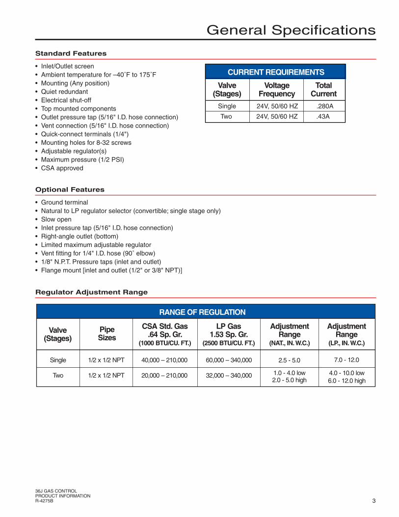
1" Pressure Drop Capacity
1" PRESSURE DROP CAPACITY(1/2" x 1/2" PIPE SIZE)
0
50
100
150
200
250
0.4 0.6 0.8 1 1.2 1.4 1.6 1.8 2
DIFFERENTIAL PRESSURE (IN. W.C.)
NA
T. G
AS
FL
OW
(K
BT
U/H
R)
1/2 x 1/2
Pipe Sizes(NPT)
140,000 BTU/HR
CSA Std. Gas.64 Sp. Gr.
(1000 BTU/CU. FT.)
226,800 BTU/HR
LP Gas1.53 Sp. Gr.
(2500 BTU/CU. FT.)
1.0" PRESSURE DROP CAPACITY
36JGASCONTROLPRODUCTINFORMATIONR-4275B 5
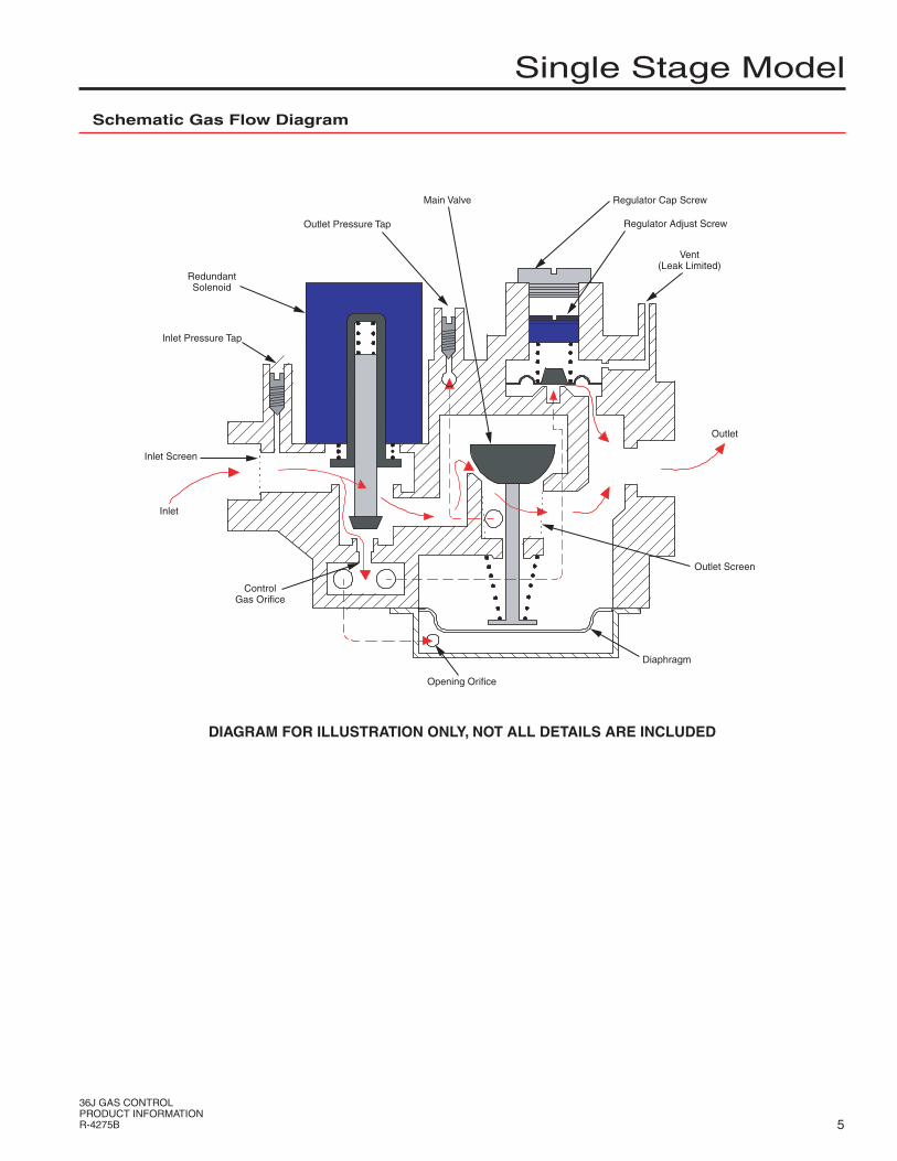
Schematic Gas Flow Diagram
SingleStageModel
DIAGRAM FOR ILLUSTRATION ONLY, NOT ALL DETAILS ARE INCLUDED
RedundantSolenoid
Outlet Pressure Tap
Inlet Pressure Tap
Inlet Screen
Inlet
ControlGas Orifice
Opening Orifice
Diaphragm
Outlet Screen
Outlet
Vent(Leak Limited)
Regulator Adjust Screw
Regulator Cap ScrewMain Valve

36JGASCONTROLPRODUCTINFORMATION
R-4275B6
Standard Open Control
SingleStageModel
Slow Open Control
Thiscontrolhasastandardopeningcharacteristic,whichissuitableforawiderangeofapplications.Itprovidesafastrisetofullpressureuponenergizingthesolenoid.Regulator LPspringconversionkitsareavail-ableforthiscontrol.
0 1 2 3 4 5 6 7 8 9 10
0
0.5
1
1.5
2
2.5
3
3.5
4
4.5
5
SECONDS
INC
HE
S W
.C.
36J STANDARD OPEN GAS VALVE(.019 OPENING ORIFICE)
Thiscontrolhasaslowopeningcharacteristic.Itprovidesaslowincrease ofgastofullpressureforsmootherignition,asmayberequiredbysomeap-plications.
Thereareoptionsavailable:B.VerySlowOpeningorificeC.SlowOpeningorificeD.IntermediateOpeningorifice
Convertible Regulator
NOTE:TYPICALOPENINGCURVENATURALGAS100,000BTU/HR.7"W.C.INLET/3.5"W.C.OUTLETOPENING CHARACTERISTICS WILL VARY WITH FLOW RATE AND APPLICATION.
0 1 2 3 4 5 6 7 8 9 10
0
0.5
1
1.5
2
2.5
3
3.5
4
4.5
5
SECONDS
INC
HE
S W
.C.
36J SLOW B
0 1 2 3 4 5 6 7 8 9 10
0
0.5
1
1.5
2
2.5
3
3.5
4
4.5
5
SECONDS
INC
HE
S W
.C.
36J SLOW C
0 1 2 3 4 5 6 7 8 9 10
0
0.5
1
1.5
2
2.5
3
3.5
4
4.5
5
SECONDS
INC
HE
S W
.C.
36J SLOW D
Theconvertibleregulatoroptionforthiscontrolinvolvesaconstruction,whichpermitseasyNaturaltoLPconversion(orviceversa)byremoving,invertingandreplacingtheregulatorcapscrew.Thisfeatureeasilylendsitselftouseinmobilehomesandinfra-redapplications
0 1 2 3 4 5 6 7 8 9 10
0
0.5
1
1.5
2
2.5
3
3.5
4
4.5
5
SECONDS
INC
HE
S W
.C.
36J CONVERTIBLE GAS VALVE
NOTE:TYPICALOPENINGCURVENATURALGAS100,000BTU/HR.7"W.C.INLET/3.5"W.C.OUTLET
NOTE:TYPICALOPENINGCURVENATURALGAS100,000BTU/HR.7"W.C.INLET/3.5"W.C.OUTLET

36JGASCONTROLPRODUCTINFORMATIONR-4275B 7
SingleStageModel
HSI CONTROL.ThethermostatcallsforheatandenergizestheHSIcontrol.Ifsystemisequippedwithprepurge,thepurgefanisenergizedandpowerwill bedelayedthirtysecondsbeforeapplicationtothesiliconcarbideignitor.Ifprepurgeisnotselected,theignitorispoweredwithinonesecond.Theignitorheatsupandattheendoftheheatingperiod,theredundantandmainvalvesareopened.Aflamemustbedetectedwithinafixedtimeperiodorbothvalvesclose,theignitoristurnedoffandtheHSIcontrollocksoutunlessthesystemisequippedwithretry.Retryindicatestheignitionsequencewillberepeatedforatotalofthreetriesifflameisundetectedorlostwithin30secondsofignition.
Accessories:HSIcontrol,SenseElectrode,SiliconCarbideIgnitor,SiliconNitrideIgnitor
INTEGRATED CONTROL.The50A55or50A65IntegratedHotSurfaceIgnitioncontrolsemployamicroprocessortocontinuouslymonitor,analyze, andcontroltheproperoperationofthegasburner,inducer,andfan.Signalsinterpretedduringcontinualsurveillanceofthethermostatandflamesensingelementinitiateautomaticignitionoftheburner,sensingoftheflame,andsystemshut-offduringnormaloperation.Thecontrolincorporatessystemfaultanalysisforquickgasflowshut-off,coupled withautomaticignitionretryuponsensingafaultcorrection.
System Applications – Hot Surface Ignition
System Applications – Direct Spark Ignition
HEAT COOL PARK PARK
CIRCULATORBLOWER
CIRCNEU IND
INDNEU
INDUCER
K1a K1b
K2 K4
RRO2
RO1ROLLOUTSWITCH
THXFMRHOT
XFMRNEU
TRC
YGW
24 VAC
COMPRESSORCONTACTORCOIL
THERMOSTAT
R
YGW
HLI
AUX.LIMIT
HIGHLIMIT
PRESSURESWITCH
HLOPS
K8
K7
GASVALVE
MVMVGNDLIGNFP2FP1
IGNITOR
FLAMESENSEPROBE
LINE HOT
LINE NEU120 VAC
THERMOSTAT
HOT LINE VOLTAGE NEUTRAL
COMMON (“C”)W R
LINE VOLTAGE
LOW VOLTAGE
REDUNDANTVALVE
TRANSFORMER24 VOLTS AC
60 Hz
MAINVALVE
MV
MV
TR
TH
FP
GND
L
IGN
BLACK
SILICON CARBIDEIGNITOR
WH
ITE
BLA
CK
LIM
IT
FLAMESENSOR PROBE
Thethermostatcallsforheatandsimultaneouslyener-gizestheDSIcontrolmoduleandgasvalvesolenoid.Sparksattheignitionelectrodesignitethegasatthemainburner.Flameissensedthroughtheelectrodesbytheflamedetectioncircuitandshuts offthesparking.Ifflameisnotestablishedwithinafixedtimeperiod(lock-outtime)mainandredundantvalvesclose,sparkingceasesandthecontrolmodulelocksout.
Accessories:DSIcontrol,Electrodes
MAINVALVE
MV
MV
TR
TH
24V.
GND
REDUNDANTVALVE
THERMOSTAT
SPARK RETURN
DSICONTROL
H.V
.
LEA
D
36JGASCONTROLPRODUCTINFORMATION
R-4275B8
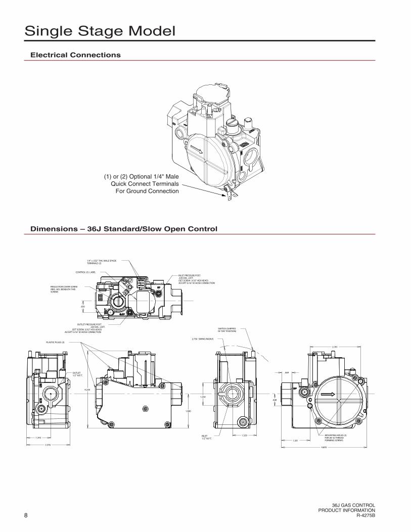
SingleStageModel
Electrical Connections
Dimensions – 36J Standard/Slow Open Control
2.376
1.343
OUTLET1/2" N.P.T.
4.238
1.880
1.250
1.329INLET1/2" N.P.T.
2.750 SWING RADIUS
SWITCH (SHIPPEDIN "ON" POSITION)
4.693
.569
CONTROL I.D. LABEL
REGULATOR COVER SCREW(REG. ADJ. BENEATH THISSCREW)
1/4" x .032" THK. MALE SPADETERMINALS (2)
PLASTIC PLUGS (3)
.650
INLET PRESSURE POST.339 DIA. +DFT.(SET SCREW: 3/32" HEX HEAD)ACCEPT 5/16" ID HOSE CONNECTION
OUTLET PRESSURE POST.339 DIA. +DFT.
(SET SCREW: 3/32" HEX HEAD)ACCEPT 5/16" ID HOSE CONNECTION
.648
MOUNTING HOLES (2)FOR #8-32 THREADFORMING SCREWS1.561
2.781
(1) or (2) Optional 1/4" MaleQuick Connect Terminals
For Ground Connection

36JGASCONTROLPRODUCTINFORMATIONR-4275B 9
Schematic Gas Flow Diagram
TwoStageModel
DIAGRAM FOR ILLUSTRATION ONLY, NOT ALL DETAILS ARE INCLUDED
Redundant Solenoid
Inlet Screen
Control GasOrifice
Opening OrificeDiaphragm
Outlet Screen
Vent (Leak
Limited)
Lo Fire RegulatorHi Fire Regulator
Main Valve
Outlet Pressure TapRegulator
Selector Valve
Outlet
Inlet
Inlet Pressure Tap

36JGASCONTROLPRODUCTINFORMATION
R-4275B10
TwoStageModel
Standard Open Control
Thiscontrolhasdualoutletpressurelevels,whichisdesirableforhighefficiencyapplications.Itprovidesafastrisetofirststagepressureuponenergizingthesinglestagesolenoid.Then,ifmorepressurelevelisrequiredtosatisfyheatingrequirement,energizingasecondstagesolenoidcanattainahigherpressurelevel.RegulatorLPspringconversionkitsareavailableforbothpressurelevelsonthiscontrol.
0 1 2 3 4 5 6 7 8 9 10
0
0.5
1
1.5
2
2.5
3
3.5
4
4.5
5
SECONDS
INC
HE
S W
.C.
36J TWO STAGE GAS VALVE
Slow Open Control
Thiscontrolhasdualoutletpressurelevels,whichisdesirableforhighefficiencyapplications.Itprovides aslowerrisetofirststagepressureuponenergizingthesinglestagesolenoid.Ifmorepressureisrequiredtosatisfyheatingrequirement,energizingasecondstagesolenoidcanattainaslowerrisetoahigherpressurelevel.Thisslowerriseconditionisdependentonthesize oforificeused.RegulatorLPspringconversionkitsforbothpressurelevelsareavailableforthiscontrol.
0
0.5
1
1.5
2
2.5
3
3.5
4
4.5
5
0 1 2 3 4 5 6 7 8 9 10 11 12 13 14 15 16 17
SECONDS
INC
HE
S W
.C.
36J TWO STAGE GAS VALVE
NOTE:TYPICALOPENINGCURVENATURALGAS100,000BTU/HR.7"W.C.INLET/3.5"W.C.OUTLET
NOTE:TYPICALOPENINGCURVENATURALGAS100,000BTU/HR.7"W.C.INLET/3.5"W.C.OUTLET

36JGASCONTROLPRODUCTINFORMATIONR-4275B 11
TwoStageModel
Electrical Connections
(1) OR (2) OPTIONAL 1/4" MALE QUICK CONNECT TERMINALS FOR GROUND CONNECTION
(1) OR (2) OPTIONAL 1/4" MALE QUICK CONNECT TERMINALS FOR GROUND CONNECTION
(4) MALE QUICK CONNECT TERMINALS 3-PIN AMP CONNECTOR
Dimensions
2.376
1.329
OUTLET - 1/2" N.P.T.(DUST PLUG INSTALLED)
4.243
1.880
1.250
1.329
INLET - 1/2" N.P.T.(DUST PLUG INSTALLED)
2.750SWINGRADIUS
4.693
.500
CONTROL I.D. LABEL
REGULATOR COVER SCREWS(REG. ADJ. BENEATH THESESCREWS)
SWITCH(SHIPPEDIN "ON"POSITION)
AMP MATE-N-LOK CONNECTORCONNECTS AMP 480700
OUTLET PRESSURE POSTSET SCREW: 3/32" HEX HEAD
(.339 DIA. + DFT.)ACCEPTS 5/16" HOSE CONNECTION
INLET PRESSURE POSTSET SCREW: 3/32" HEX HEAD(.339 DIA. + DFT.)ACCEPTS 5/16" HOSE CONNECTION
(4) Quick Connect Terminals
1.272
72,16
110,13
.379
.650
1.561
2.781
1.339
.648

ModelsAvailable
ACCESSORIES
Regulator Conversion Kits
F92-0659 NaturalGastoLP SingleStage
F92-0737 NaturalGastoUnregulatedLP
SingleStage
F92-1008 NaturalGastoLP TwoStage
F92-0656 LPtoNaturalGas SingleStage
F92-1011 LPtoNaturalGas TwoStage
F27-0373 FlangeMountKit SingleorTwoStage
www.white-rodgers.comwww.emersonclimate.com
R-4275B1132
White-Rodgersisadivision ofEmersonElectricCo.
TheEmersonlogoisa trademarkandservicemark ofEmersonElectricCo.
OPTIONS FEATURES
BASIC MODEL NUMBER SERIES
TYPE NUMBER CODING
2XX
5XX
6XX
1/2 NPT x 1/2 NPTPressure Tap Towers
1/2 NPT x 1/2 NPT1/8 NPT Press. Taps
1/2 NPT x 1/2 NPT Bottom Outlet1/8 NPT Press. Taps
Number Pipe Size (inlet x outlet)
PACK OPTION
Blank
B1
P1
Single Pack
Bulk Pack
Pallet Pack
Pack Code Description
36J XX TYPEX XX
ModelNumber
36J22
36J23
36J24
36J26
36J29
36J30
36J52
36J54
36J55
Notes:A – Standard Opening Orifice B – Very Slow Opening Orifice C – Slow Opening Orifice D – Intermediate Opening Orifice E – 2 Stage Slow Opening Orifice F – No Switch
Fast
Ope
n
Slo
w O
pen
Con
vert
ible
Two
Sta
ge
Not
es
X
X
X
A
B
C
F
A
C
D
A
C
X
X
X
X
X
X
X
X
X
X
X
None
Y
Alpha Numeric
24V 50/60 HZ
24V 50/60 HZ
Voltage
Std. Adj.
Limited Max. Adj. Reg.
Additional Features
VOLTAGE / FEATURE LETTER CODING


![ESD.36 L15 Case 3 SSN 688i [Read-Only] file23 Oct 2003 - ESD.36J SPM 9 + -688 688i External comparison- 688 vs. 688i 23 Oct 2003 - ESD.36J SPM 10 + -AN/BSY-1 Combat System](https://img.dokumen.tips/doc/110x75/5cd021d388c99375718d420e/esd36-l15-case-3-ssn-688i-read-only-oct-2003-esd36j-spm-9-688-688i-external.jpg)