Embed Size (px)
Citation preview

VARIABLE DISPLACEMENTHYDRAULIC PUMPS 313 SERIES
TECHNICAL CATALOGUE
“PNEVMOSTROIMASHINA” JSC

2
www.psm-hydraulic coms.
Dear partners!
We are pleased to draw your attention to the technical catalogue containing information about variable displacement axial piston hydraulic pumps 313 series, intended for usage in mobile and stationary assemblies.
“Pnevmostroimashina” JSC – leading Russian machine building company with century-old history, specialized in design, manufacture and sale on domestic and international markets of the following kinds of hydraulic equipment:
- fixed and variable displacement hydraulic motors and pumps;- hydrostatic transmissions;- pumping and motor units;- hydraulic valve equipment;- hydraulic drive elements.
Production activity of our enterprise is based on long-term engineering potential and constant introduction of new equipment and technologies.
All the products manufactured by our enterprise are 100 % tested on the benches and at laboratories with modern measuring and testing equipment.
The quality management system of products design and manufacture is certified by the international company Lloyds' Register Quality Assurance to the conformity of the international standard BS EN ISO 9001:2008, certificate No. SPB0006283.
We have tried to present our product range in the most comprehensive and easily understandable way and we shall be glad if this catalogue will help you to apply and use our articles.
We shall appreciate your kind comments and suggestions on the present edition and on improvements of our products by tel.: +7 343 2646650, fax: +7 343 2299602 or by e-mail: [email protected]
Best regards,
Alexander AnGeneral Director
®PSM-Hydraulics
We tried to present the detailed information about variable displacement hydraulic pumps 313 series and will be glad if the catalogue will help you to apply and use our products in a proper way.
3
1. Contents2. General information..................................................................................................................................................................................................................43. Description of hydraulic pumps 313 series.....................................................................................................................................................................54. Structural designation diagram of hydraulic pumps 313 series.............................................................................................................................65. Technical parameters............................................................................................................................................................................................................86. Maintenance restrictions....................................................................................................................................................................................................97. Requirements for working fluids.................................................................................................................................................................................108. Allowed radial and axial loads on shaft....................................................................................................................................................................119. Regulation.............................................................................................................................................................................................................................12
9.1. Pump with proportional positive hydraulic control (313 … 007.3(4)) Pump with proportional positive hydraulic control and valve «OR» for regulator connection to servo supply
(313 ... 007.303(304)) Pump with proportional positive hydraulic control and cut off valve in control line (313 … 007.38(48)) Pump with proportional positive hydraulic control with cut off valve in control line and valve «OR»for regulator connection
to servo supply (313 … 007.383(483))........................................................................................................................................................129.2 Pump with constant pressure change valve and pressure cut off valve (313 … 200.32)........................................149.3 Pump with constant pressure regulator (313 … 300.3)................................................................................................................159.4 Pump with constant power regulator (313 … 500.3)................................................................................................................169.5 Pump with constant power regulator and cut off valve in high pressure line (313 … 500.32)......179.6 Pump with constant power regulator with mechanical blocking of regulator for installation at V=0 cc(313 … 55. 500.4А).......................................................................................................................................................................................................189.7 Pump with constant power regulator, hydraulic positive control (313 … 501.303).............................................................199.8 Pump with constant power regulator and negative control (313 … 502.3).........................................................209.9 Pump with constant power regulator, positive control and limitation of upper responce level
313 ... 507.303)...............................................................................................................................................................219.10 Pump with constant power regulator, positive control, limitation of upper responce level and cut off valve in
servo line (313 ... 507.383....................................................................................................................................................................................229.11 Pump with constant power regulator, with hydraulic positive control and block of constant pressure change (LS) in servo line
(313 … 507.39)Pump with constant power regulator, with hydraulic positive control, block of constant pressure change (LS) in servo line and valve «OR» for regulator connection to servo supply 9.12 Pump with positive discrete electric control (313…605.303, 313 … 606.303).......................................................................269.13 Pump with direct shift (manual regulation) of working displacement (313 … 803.3, 804.3).................................279.14 Pumps with direct control (313… … 8…А(В,С).3).......................................................................................................................289.15 Pump with constant pressure regulator with remote hydraulic pilot (313…80В.300П + 313.084.7020)..........29
10. Overall and mounting dimensions.........................................................................................................................................................................3110.1 Size 12 cc................................................................................................................................................................................................................3110.2 Size 28 cc................................................................................................................................................................................................................3210.3 Size 55 cc................................................................................................................................................................................................................3710.4 Size 56 cc................................................................................................................................................................................................................4110.5 Size 80 cc................................................................................................................................................................................................................4310.6 Size 107 cc.............................................................................................................................................................................................................4710.7 Size 112 cc.............................................................................................................................................................................................................5110.8 Size 160 cc.............................................................................................................................................................................................................5310.9 Size 250 cc.............................................................................................................................................................................................................57
11. Recommendations for installation...................................................................................................................................................................................61
www.psm-hydraulic coms.
(313 ... 507.393)..........24

4
Hydraulic pumps 313 series – the product of global usage designed for world market according to international standards
PurposePumps 313 series are intended to convey mechanical energy of input shaft rotation to the energy of working fluid flow with stepless regulation of flow. Pumps provide incontinuous change of working fluid flow from zero to max value
Design Pump design is based on bent axis axial piston circuit
Size Hydraulic pumps 313 series can have the following working displacements313…12313…28313…55313…56313…80313…107313…112313…160313…250
-11,6 cc/rev-28 cc/rev-55 cc/rev-56 cc/rev-80 cc/rev-107 cc/rev-112 cc/rev-160 cc/rev-250 cc/rev
Working pressure max -40 MPapeak -45 MPa
Connection mounting flange - ISO 3019/2, 4 bolts
high pressure hoses connection flanges
-SAE 1” 3000psi-SAE 1” 6000psi-SAE 1 1/4” 6000psi
ports of drain lines - as per GOST 26065 / ISO 6149-1- as per ISO 9974-1 / DIN 3852-1
splined shafts -as per GOST 6033-80-as per ANSI B92.1a-as per DIN 5480
keyed shaft -as per DIN 6885
Regulation mechanicalhydraulic controlelectric control
2. General information
www.psm-hydraulic coms.

5
3. Description of hydraulic pumps 313 series
Hydraulic pump has cast iron housing which contains:-main shaft mounted on two radial thrust roller conical bearings. Hydraulic pump is manufactured with splined and keyed shafts;-rotary group containing cylinders block, spherical port plate, center pin and working pistons;-screws for limitation of working displacement;-gasket cap, installed from the side of mounting flange of hydraulic pump. The gasket cap contains gasket sealing providing reliable leakproofness of hydraulic pump housing chamber on main shaft.
Hydraulic pump can be equipped with rotation speed sensor.Regulator block located at angle to hydraulic pump housing includes the following:
-spool and sleeve;-regulator piston;-regulator.
Hydraulic pumps are equipped with different versions of regulation mechanisms.
General view
www.psm-hydraulic coms.
Spined shaft Cylinders block Port plate
Regulator cap
Lever
Piston
Pin
Spool
Sleeve
Key shaft
Adjusting screw of Vmax limitation
Regulator housing
Adjusting screw of Vmin limitation

6
А В C D E F G H I J K L M
3 1 3 ∙ ∙ ∙ ∙ ∙ ∙
● = serial productionо = possible version- = not available
code designation313 type (series) 313
В-version
code designation 12 28 55 56 80 107 112 160 2502 roller bearings of shaft group, brass block of cylinders ● ● - ●
∗ - - ●∗ - -3 conical bearings of shaft group, brass block of cylinders ● ● ● ● ● ● ● ● ●
4 conical bearings of shaft group, steel block of cylindersfor 12, 28 cc/rev - roller bearings of shaft group
● ● ● ● ● ● ● ● ●
С - working displacement
code 12 28 55 56 80 107 112 160 250designation 12 cc/rev 28 cc/rev 55 cc/rev 56 cc/rev 80 cc/rev 107 cc/rev 112 cc/rev 160 cc/rev 250 cc/rev
D - regulation type
code designation 12 28 55 56 80 107 112 160 2500 proportional - ● ● ● ● ● ● ● ●
1 negative discrete electric control - ● ● ● ● ● ● ● ●
2 LS - ● ● - ● ● - ● ●
3 constant pressure ● ● ● - ● ● - ● ●
5 constant power - ● ● ● ● ● ● ● ●
6 positive discrete electric control - ● ● ● ● ● ● ● ●
8 without control switch ● ● ● ● ● ● ● ● ●
E - limitation of working displacement
code designation 12 28 55 56 80 107 112 160 2500 without limitation ● ● ● ● ● ● ● ● ●
5 with limitation Vmin ● ● ● ● ● ● ● ● ●
7 with limitation Vmax ● ● ● ● ● ● ● ● ●
9 with limitation Vmin and Vmax ● ● ● ● ● ● ● ● ●
F - control type
code designation 12 28 55 56 80 107 112 160 2500 not available (for regulation types 2, 3, 5) ● ● ● ● ● ● ● ● ●
1 hydraulic positive - - - ● - - ● - -2 hydraulic negative - ● ● ● ● ● ● ● ●
3 mechanical, shift with progressive motion ● ● ● ● ● ● ● ● ●
4 mechanical, shift with rotational motion ● ● ● ● ● ● ● ● о5 electro, discrete (24 V) - ● ● ● ● ● ● ● ●
6 electro, discrete (12 V) - ● ● ● ● ● ● ● ●
7 hydraulic positive with internal limitation - ● ● ● ● ● ● ● ●
A direct control, double-chamber multifold piston - ● о ● о ● ● ● ●
B direct control, single-chamber multifold piston - ● о ● о ● ● ● ●
C direct control, double-chamber equilateral piston - ● - ● ● ● ● ● -D electro, proportional 12 V - ● ● - о ● - ● оE electro, proportional 24 V - ● ● - о ● - ● о
G - direction of rotation and shaft version
code designation 12 28 55 56 80 107 112 160 2503 right, splined as per 6033-80 ● ● ● ● ● ● ● ● ●
4 left, splined as per GOST 6033-80 ● ● ● ● ● ● ● ● ●
5 right, keyed ● ● ● ● ● ● ● ● ●
6 left, keyed ● ● ● ● ● ● ● ● ●
7 right, splined as per DIN 5480 - - ● ● ● ● ● ● ●
8 left, splined as per DIN 5480 - - ● ● ● ● ● ● ●
4. Structural designation scheme of hydraulic pumps 313 series
A – type (series)
www.psm-hydraulic coms.

7
H - secondary control
code designation 12 28 55 56 80 107 112 160 2500 not available ● ● ● ● ● ● ● ● ●
2 pressure cut off valve - ● ● ● ● ● ● ● ●
8 cut off valve in control line - ● ● ● ● ● ● ● ●
9 LS block - ● ● ● ● ● ● ● ●
А regulator mechanical blocking for installation at V = 0 cc/rev. - ● ● ● ● ● ● ● ●
I - mounted in hydraulic valve equipment
code designation 12 28 55 56 80 107 112 160 2500 not available - ● ● ● ● ● ● ● ●
1 relieve valve - ● ● ● ● ● ● ● ●
3 valve «OR» for regulator connection to servo supply - ● ● ● ● ● ● ● ●
4 valve «OR» for regulator connection to servo supply, output relieve valve - ● ● ● ● ● ● ● ●
J - type of hydraulic system
code designation 12 28 55 56 80 107 112 160 2500 for open circuit ● ● ● ● ● ● ● ● ●
K - location and type of working channels, mounting flange ISO 3019/2, 4 holes
code designation 12 28 55 56 80 107 112 160 2500∗∗ 1 flange on buttend, 1 flange sideways ● ● ● ● ● ● ● ● ●
L - shaft sealing material
code designation 12 28 55 56 80 107 112 160 250В NBR ● ● ● ● ● ● ● ● ●
F FKM ● ● ● ● ● ● ● ● ●
M - climatic version
code designation 12 28 55 56 80 107 112 160 250У1 moderate climate, open air location ● ● ● ● ● ● ● ● ●
ТВ1 tropical humid climate, open air location ● ● ● ● ● ● ● ● ●
ОМ1 marine climate, open air location ● ● ● ● ● ● ● ● ●
∗ - not applied for new developments∗∗ - allowed not to specify while ordering
www.psm-hydraulic coms.
∗∗
∗∗
∗∗
∗∗

8
ParameterValues for variable pumps 313 series with the following working displacement
12 28 55 56 80 107 112 160 250Working displacement Vg, cc/rev
- min Vg min
- max Vg max
011,6
028
055
1656
080
0107
31112
0160
0250
Rotation speed n, rpm- min nmin
- nominal nnom
- max nmax at input pressure 0,08 MPa- limit npeak at input pressure 0,2 MPa
400240040006000
400180030004750
400150025003750
400150025003750
400150022403350
400120020003000
400120020003000
00120017502650
400960
15002100
Feed Q, l/min- min Qmin
- nominal Qnom
- max Qmax
- limit Qpeak
4,6427,8446,4069,60
11,2050,4084,00
133,00
22,0082,50
137,50206,25
22,4084,00
140,00210,00
32,00120,00179,20268,00
42,80128,40214,00321,00
44,80134,40224,00336,00
64,00192,00280,00424,00
100,00240,00375,00525,00
Discharge pressure (change) ∆P, MPa- nominal ∆Pnom
- max working ∆Pmax (for 313.3 series)
- max working ∆Pmax (for 313.4 series)
20
32
-
20
32
-
20
35
40
20
35
40
20
35
40
20
35
40
20
35
40
20
35
40
20
35
40Input pressure, MPa- min (absolute)- max
0,08
0,2
0,08
0,2
0,08
0,2
0,08
0,2
0,08
0,2
0,08
0,2
0,08
0,2
,08
0,2
0,08
0,2
Pressure of regulator stable operation, min, MPa 3 3 3 3 3 3 3 3 3
Consumed power N, kW- nominal Nnom (at nnom, Vg max, Pnom)- max Nmax (at nmax, Vg max, Pmax) for 313.3 series- max Nmax (at nmax, Vg max, Pmax) for 313.4 series
19,3324,75
35,0044,80
57,2980,2191,67
58,3381,6793,33
74,67104,53119,47
89,17124,83142,67
93,33130,67149,33
116,67163,33186,67
156,25218,75250,00
Driven torque T, Nm- nominal Тnom (at Vg max, Pnom)- max Tmax (at Vg max, Pmax) for 313.3 series- max Tmax (at Vg max, Pmax) for 313.4 series
46,1559,08
111,41142,60
218,84306,37350,14
222,82311,94356,51
318,31445,63509,30
425,74596,04681,18
445,63623,89713,01
636,62891,27
1018,59
994,721392,611591,55
0,95 0,95 0,95 0,95 0,95 0,95 0,95 0,95 0,95
0,90
9 15,5 24 22 38 40 37,5 55 85
* values of torque Т and power N are given without consideration of efficiency coefficient
Determination of nominal pump size:
5. Technical parameters
www.psm-hydraulic coms.
volumetric efficiency coefficient-efficiency coefficient
efficiency coefficient
Feed efficiency
Fulle coefficient

9
Requirements for hydraulic systems:1. Hydraulic system of main unit which contains the pump shall have devices for controlling the oil temperature in the tank, the pressure in input and output lines of pump.2. Relieve valve of hydraulic system shall be adjusted for pressure not higher than max output pressure given in the Table with technical parameters.3. Avoid operation in the modes with frequent overloads. The operation time of the unit at 40 MPa within the recommended range of working fluid temperature shall not exceed 10-12 s. with the interval not less than 10 min.4. At lower limit of maintenance temperature to -25ºC it is recommended to use the material of shaft sealing (gasket) FKM, at lower limit to -40ºC - NBR.
Requirements for piping:1. The section of pressure pipe is not recommended to be less than the area of the pump corresponding hole. Prohibited to accept the section of sucking pipe less than the section of pump sucking hole.2. Each pressure pipe shall be checked for leak-proofness with static pressure of working fluid which is 1,6 Рmax (50 MPa) during 5 min.
6. Maintenance restrictions
www.psm-hydraulics.com

10
The working fluid shall conform to the following parameters:
Cleanliness grade as per GOST 17216Kinematic viscosity, mm2/s (cSt):-optimal-max launch-min short term
1220–351500
10Filtration fineness (nominal), mkm 25
Maintenance temperature, °С:-max-min
+75–40
Working fluids recommended for usage:
Oil brand
Designation as per GOST
17479.4-87
Viscosity class as per ISO 3448
VG-15 VG-22 VG-46Group as per DIN 51524
HVLP 15 HLP 22 HVLP 46 HLP
ВМГЗ ТУ 38.101479-86
МГЕ-10А ОСТ 38.01281-82
МГ-15-В (с)МГ-15-В
SHELLTellus S2 V15
Substituent
АМГ-10 6794-75∗GOSTМГ-15.Б MOBIL DTE 11M
АУП ТУ 38.1011258-89 МГ-22-БCASTROL Hyspin AWН 15
СДМ-15 ТУ 0253-001-49319233-02
(“SDM Zapchast-Service” Ltd.)МГ-15-В
SHELLTellus S3 M22
MOBIL DTE 22
CASTROLHysрin AWS 22
МГЕ-46-В ТУ 38.001347-83 МГ-46-ВSHELLTellus S2 V46
SHELLTellus S2 M46
Substituent
И-30А GOST 20799-88 И-Г-А-46
MOBIL DTE 15
CASTROLHyspin AWH 46
MOBIL DTE 25
CASTROL
∗ - only for regions with severe climate∗ - strictly prohibited to mix oils
7. Requirements for working fluids
www.psm-hydraulic coms.
17479.3-85,
Hyspin AWH 46

11
Operation lifetime of hydraulic pump bearing group directly depends on the forces acting on output shaft of hydraulic pump from outside. To avoid early failure of hydraulic pump during project works observe the restrictions for external forces on output shaft of hydraulic pump.
Values of limit loads on shaft are given in the Table:
Parameter Values for pumps with the following working displacement:
12 28 (55) 56 80 (107) 112 160 250а, mm 20 25 25 25 27,5 27,5 29Fmax, N 2748 5361 8962 11657 13610 18317 23924F/Р, N/MPa 61 119 199 291 302 452 590±Fax max, N 200 315 500 710 900 1120 1600±Fax max/Р, N/MPa 26 46 75 96 113 151 196
а – distance of force F application from shaft collar; The scheme of acting loads is given on the Fig.
Fmax – max radial load at optimal angle of gear installation;
F/P – radial load acting at pressure P (additional load allowed at pressure P);
±Fax max – max allowed axial load at standstill;
±Fax max/P – max allowed axial load at operation with pressure P.
Direction of max allowed axial load shall be considered:
-Fax max – bearings lifetime is increased;
+Fax max – bearings lifetime is decreased (avoid if possible)
Values of limit loads on hydraulic pump shaft are given for optimal angles of gear (а) and V-belt (б) drives installation.
8. Allowed radial and axial loads on shaft
1 – for hydraulic pump of right rotation (inlet B under pressure);2 – for reversible drive;3 – for hydraulic pump of left rotation (inlet A under pressure).The choice of other angle of gear installation shall be negotiated with the Manufacturer.
а б
www.psm-hydraulics.com

12
9. Regulation
Pump is intended for:- changing feed Q in dependence of operator signal;- providing automatic pump output for min displacement Vmin at adjusted cut-off pressure Ротс in hydraulic system.
Pump operationIn intial position, at absence of control pressure Ру, the pump has min working displacement Vmin, feed Qmin and min consumed power Nп.
RegulationAt increase of control pressure Ру, starting with the pressure of regulation beginning Рун, working displacement V of pump is proportion-
ally increasing, which leads increase of feed Q (consumed power Nп). Having achieved the max working displacement Vmax, at control pres-sure equal to regulation end pressure Ру = Рук, the pump will have max feed Qmax (consumed power Nп).
Cut-off valve (screw Z0) controls working pressure Р at pump output and provides automatic drop of control pressure Ру, at pressure Р, exceeding the pressure of cut-off valve adjustment Pотс which leads smooth output of pump to initial position.
Feed Q (consumed power Nп), if necessary, can be restricted with one of the following ways: - limitation of max working displacement Vmax of pump; - limitation of control pressure Ру with screw Z;- limitation of working pressure Рmax of hydraulic system.
ATTENTION:Cut-off valve is recommended to adjust for 2 MPa lower than adjustment pressure of relieve valve in hydraulic system.The standard range Pун=0,6…1 MPa, standard value at factory adjustment Pун=0,6…0,8 MPa, at that the range of control pressure
change ΔPу=1,2…1,5 MPa, the range Pук=1,8…2,3 MPa. The range of pressure cut-off valve adjustment Ротс=5…40 MPa.While ordering hydraulic pumps specify the value of regulation beginning pressure Pун, of min and max working displacement
Vmin, Vmax, of cut off valve adjustment pressure Pотс. Hydraulic pump regulator operates based on working pressure in hydraulic system, the min value of working pressure for normal operation of regulator: -3 MPa. If the pressure is lower, it is necessary to order the pump with valve «OR» for regulator connection to
servo supply (313…007.303(403) or 313…007.383(483)).
Diagrams of dependance between the change of feed Q and working displacement V from pressure change Р
9.1 Pump with proportional positive hydraulic control (313 ... 007.3(4)) Pump with proportional positive hydraulic control and valve «OR» for regulator connection
to servo supply (313 … 007.303(304)) Pump with proportional positive hydraulic control and cut off valve in control line (313 …
007.38(48)) Pump with proportional positive hydraulic control with cut off valve in contol line and valve
«OR» for regulator connection to servo supply (313 … 007.383(483))
www.psm-hydraulic coms.
control
controlcut-off control beginningP

13
Hydraulic circuits of pumps
313…3(4) 313…303(403) 313…38(48) 313…383(483)
Designation on hydraulic circuit:A - pressure lineS - suction lineR - hole for deaeration (plugged in)Y - input line for servo supply of regulator, not less than 3 MPa, socket М16x1,5-7HX - control pressure line, Ру max=3,5 MPa, М12х1,5-7Н GOST 25065-90Z0 - pressure cut off valve Ротс adjusting screw
Z, Z1 - adjusting screw of regulation beginning pressure Рун
www.psm-hydraulics.com
14
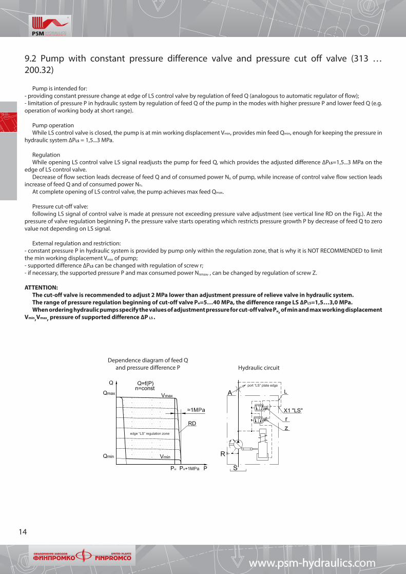
Pump is intended for:- providing constant pressure change at edge of LS control valve by regulation of feed Q (analogous to automatic regulator of flow);- limitation of pressure Р in hydraulic system by regulation of feed Q of the pump in the modes with higher pressure Р and lower feed Q (e.g. operation of working body at short range).
Pump operationWhile LS control valve is closed, the pump is at min working displacement Vmin, provides min feed Qmin, enough for keeping the pressure in
hydraulic system ∆РLS = 1,5...3 MPa.
RegulationWhile opening LS control valve LS signal readjusts the pump for feed Q, which provides the adjusted difference ∆РLS=1,5...3 MPa on the
edge of LS control valve.Decrease of flow section leads decrease of feed Q and of consumed power Nп of pump, while increase of control valve flow section leads
increase of feed Q and of consumed power Nп.At complete opening of LS control valve, the pump achieves max feed Qmax.
Pressure cut-off valve:following LS signal of control valve is made at pressure not exceeding pressure valve adjustment (see vertical line RD on the Fig.). At the
pressure of valve regulation beginning Рн the pressure valve starts operating which restricts pressure growth Р by decrease of feed Q to zero value not depending on LS signal.
External regulation and restriction:- constant pressure Р in hydraulic system is provided by pump only within the regulation zone, that is why it is NOT RECOMMENDED to limit the min working displacement Vmin of pump;- supported difference ∆РLS can be changed with regulation of screw r;- if necessary, the supported pressure Р and max consumed power Nпmax, , can be changed by regulation of screw Z.
ATTENTION:The cut-off valve is recommended to adjust 2 MPa lower than adjustment pressure of relieve valve in hydraulic system.The range of pressure regulation beginning of cut-off valve Pн=5…40 MPa, the difference range LS ∆РLS=1,5…3,0 MPa.When ordering hydraulic pumps specify the values of adjustment pressure for cut-off valve Pн, of min and max working displacement
Vmin,Vmax, pressure of supported difference ∆Р LS .
Dependence diagram of feed Q and pressure difference Р Hydraulic circuit
9.2 Pump with constant pressure difference valve and pressure cut off valve (313 … 200.32)
www.psm-hydraulic coms.
port “LS” plate edge
edge “LS” regulation zone
P
P

15
9.3 Pump with constant pressure regulator (313 … 300.3)
Pump is intended for providing constant pressure in hydraulic system by means of feed regulation.
Pump operationWhile pressure in hydraulic system does not exceed the pressure of regulation beginning Рн, the pump is at max working displacement
Vmах and provides max feed Qmах (point 1).
RegulationAt increase of working pressure Р, starting with pressure of regulation beginning Рн (point 1), working displacement V of pump starts to
decrease smoothly and automatically. Having achieved the min working displacement Vmin at final pressure Рк ≈ Рн +1 MPa, the pump feeds min flow necessary for compensation of leakages and providing the min consumed power Nпmin (point 2).
External regulation and restriction:- max and min feed of pump can be adjusted by changing the working displacement of pump with limiting adjusting screws;- supported pressure and max consumed power if necessary can be adjusted with screw Z;- constant pressure in hydraulic system is provided with pump only within the regulation zone. That is why it is not recommended to restrict the min working displacement Vmin of pump;- during the long maintenance of pump at zero feed Qmin 0 (more than 50 % of working cycle) at pressure Р >15 MPa, for cooling the rotary group parts it is necessary to charge the working fluid with flow Q= 8..10 % Qmax through hole R of pump.
ATTENTION:Pressure range of regulation beginning Pн=5…35 MPa.While ordering hydraulic pumps specify the values for regulation beginning pressure Pн, for min and max working displacement
Vmin, Vmax.
Dependence diagrams of torque Mп, consumed power Nп and feed Q from pressure difference Р
Hydraulic circuit of pumps
28 cc 12, 55, 80, 107, 160, 250 cc
Designation on hydraulic circuit:A - charge lineS - suction lineR - hole for deaeration (plugged in)L - regulator drain line (connect with hydraulic tank),
М12x1,5 GOST 25065-90
Z - adjusting screw for regulation beginning pressure Рн
www.psm-hydraulics.com
P P
PP

16
9.4 Pump with constant power regulator (313 … 500.3)
Pump is intended for providing constant consumed torque Мп by means of angle regulation of rotary group.
Pump operationWhile pressure in hydraulic system does not exceed the pressure of regulation beginning Рн, the pump is at max working displacement Vmax
and provides max feed Qmax.
RegulationAt increase of working pressure Р, starting with pressure of regulation beginning Рн, the working displacement of pump V starts to decrease
automatically, providing the constant consumed torque Мп and consumed power Nп.Constant consumed torque Мп and power Nп are provided within the regulation zone of pump. Having achieved the min working
displacement Vmin (when mechanical restriction is available) at pressure Рк ≈ Рн.Vmax/Vmin, the pump will have min feed Qmin, and at further pressure increase Р>Рк consumed torque Мп and power Nп will increase.
External regulation and restriction:- max feed of pump can be changed by regulation of adjusting screw for max working displacement Vmax of pump;- consumed power Nп, if necessary, can be changed by adjustment of screw Z.
ATTENTION:The range of pressure regulation begining Pн=5…25 MPa.While ordering hydraulic pumps specify the values of power Nдв and rotation speed nдв of drive engine or pressure of regulation
beginning Pн.
Dependence diagrams of consumed torque Mп, consumed power Nп and feed Q from pressure difference Р Hydraulic circuit
Designation on hydraulic circuitA - charge lineS - suction lineR - hole for deaeration (plugged in)Z - adjusting screw of regulation beginning pressure Рн
www.psm-hydraulic coms.
P P

17
9.5 Pump with constant power regulator and cut-off valve in high pressure line (313 … 500.32)
The pump is intended for providing constant consumed torque Мп by regulation of rotary group inclination angle.
Pump operation While pressure in hydraulic system does not exceed Рн the pump is at max working displacement Vmax and provides max feed Qmax.
RegulationAt increase of working pressure Р, starting with regulation beginnign pressure Рн, working displacement V of pump starts to decrease
smoothly and automatically, providing the costant torque Мп and consumed power Nп. Constant consumed torque Мп and power Nп are provided within the regulation zone of pump.
Having achieved the min working displacement Vmin at pressure Рк≈Рн . V max /V min , the pump will have min feed Qmin, and at further increase of pressure Р>Рк the consumed torque Мп and power Nп will increase.
The cut-off valve operates at pressure Р at pump output, exceeding adjustment pressure of cut-off valve Ротс. The pump enters the mode of min feed and power, dropping the feed and preventing the overheating and the drain of working fluid through relieve valve.
External regulation and restriction:- max feed of pump can be changed with regulation of screw for restriction of max working displacement Vmax of pump;- consumed power Nп, if necessary, can be changed with regulation of screw Z;- pressure adjustment of cut-off valve Ротс , if necessary, can be changed with regulation of screw Z0;
ATTENTION:Cut-off valve is recommended to be adjusted for 2 MPa which is lower than pressure adjustment of relieve valve in hydraulic
system.The range of pressure regulation beginning Pн=5…25 MPa. The range of pressure adjustment of cut-off valve Ротс=5…40 MPa.While ordering hydraulic pumps specify the values of power Nдв and rotation speed nдв of drive engine or pressure of regulation
beginning Pн, pressure of cut-off valve adjustment Pотс.
Hydraulic circuitDependence diagrams of torque Mп, consumed power Nп and feed Q
from pressure difference Р
Designation on hydraulic circuitA - charge lineS - suction lineR - hole for deaeration (plugged-in)Z - screw for adjustment of regulation beginning pressure Рн
Z0 - pressure adjusting screw Ротс of cut-off valve
www.psm-hydraulics.com

18
9.6 Pump with constant power regulator and with mechanical block of regulator for installation at V=0 cc (313 ….55. 500.4А)
The pump is intended for providing the constant consumed torque Mп, by regulation of rotary group inclination angle.
Pump operationWhile pressure in hydraulic system does not exceed the pressure of regulation beginning Рн, the pump is at max working displacement Vmax
and provides max feed Qmax.
RegulationAt increase of working pressure Р, starting with regulation beginning pressure Рн, the working displacement V of pump starts to decrease
smoothly and automatically, providing the constant consumed torque Mп and consumed power Nп. The constant consumed torque Mп and power Nп are provided within the pump regulation zone.
Having achieved the min working displacement Vmin, at pressure Pк≈Pн ∙Vmax/Vmin, the pump will have min feed Qmin, and at further further increase of pressure P>Pк consumed torque Мп and power Nп will increase.
External regulation and restriction- max feed of the pump can be changed with regulation of screw for restriction of max working displacement Vmax of pump;- consumed power Nп, if necessary, can be changed with regulation of screw Z;- regulator for installation at zero working displacement is blocked with tightening screw ν to the rest. After diesel launch turn off screw ν to the rest.
ATTENTION:The range of pressure regulation beginning Pн=5…25 MPa.While ordering hydraulic pumps specify the values of power Nдв and rotation speed nдв of driving engine or regulation beginning
pressure Pн.
Dependence diagrams of consumed torque Mп, consumed power Nп and feed Q from pressure change Р Hydraulic diagram
Designation on hydraulic diagramA - pressure lineS - suction lineR - hole for deaeration (plugged)Z - screw for adjustment of regulation beginning pressure Рн
v - screw for pump installation at zero working displacement
www.psm-hydraulic coms.
P P

19
9.7 Pump with constant power regulator, hydraulic positive control (313 … 501.303)
Pump is intended for:- providing constant consumed torque Мп by regulation of rotary group inclination angle;- regulation of pump consumed power Nп in dependence of control pressure Ру.
Pump operationAt absence of control pressure Ру=0 the pump is at min working displacement Vmin, providing min feed Qmin and consumed power Nп min.After feed of control pressure Ру, while pressure in hydraulic system does not exceed the pressure of regulation beginning Рн, the pump is
at max working displacement Vmax and provides max feed Qmax.
RegulationAt increase of working pressure Р, starting with pressure of regulation beginning Рн, the working displacement V of pump starts smooth
decreasing, providing (supporting) constant drive Мп and constant power Nп. By means of decreasing the working displacement V the feed Q decreases to min values Vmin and Qmin.
The pressure of regulation beginning Рн, drive torque Мп and consumed power Nп are determined (adjusted) with control pressure Ру.At any moment pump feed depends on control pressure Ру and working pressure Р. Constant torque Мп and consumed power Nп are provided within the zone of pump regulation.Having achieved the min working displacement Vmin at pressure Pк≈Pн∙Vmax/Vmin, the pump will have min feed Qmin, and at further pressure
increase Р>Рк the consumed torque Мп and consumed power Nп will increase.
External regulation and restriction:- max feed of pump can be changed with regulation of screw for max working displacement Vmax of pump;- consumed power Nп, if necessary, can be changed with regulation of screw Z.
ATTENTION:The range of regulation beginning pressure Pн=5…25 MPa.While ordering hydraulic pumps specify the values of power Nдв and rotation speed nдв of drive engine or regulation beginning
pressure Pн, min and max working displacement Vmin, Vmax.Do not apply for new developments.
Dependence diagrams of consumed torque Mп,consumed power Nп and feed Q from pressure difference Р Hydraulic diagram
Designation on hydraulic circuit:A - charge lineS - suction lineR - hole for deaeration (plugged in)Y - input line for external feed of regulator, not less than 3 MPa, socket М16x1,5-7HX - control pressure line, Ру max=3,5 MPa, М12х1,5-7Н GOST 25065-90Z - screw for adjustment of regulation beginning pressure Рн
www.psm-hydraulics.com
P P

20
9.8 Pump with constant power regulator and negative control(313 … 502.3)
Pump is intended for:- automatic support of consumed power Nп at pressure change Р in hydraulic system by regulation of rotary group inclination angle;- pump output to the mode of min consumed power Nп min (feed Q) with hydraulic signal from operator.
Pump operationWhile pressure in hydraulic system does not exceed the pressure of regulation beginning Рн, the pump is at max working displacement
Vmax and gives max feed Qmax.
RegulationAt increase of working pressure Р, starting with regulation beginning pressure Рн, working displacement V of pump starts to decrease
automatically, providing the constant consumed power Nп of pump, at that the consumed torque Мп is constant, and pump feed Q decreases.
Having achieved the min working displacement Vmin at pressure Рк≈Рн ·Vmax/Vmin, the pump will have min feed Qmin.
Operator interference At smooth feed of control signal Ру (negative control) to line X the pump can get readjusted for less pressure of regulation beginning Рн and
already at Ру=2,5...3 MPa the working displacement V of pump is min if hydraulic system working pressure Р > 4 MPa.
External regulation and restriction:- max rotation speed of pump shall not exceed max allowed;- working displacement Vmin and Vmax of pump can be restricted with regulating screws;- pressure of regulation beginning Рн of pump can be changed with regulation of screw Z.
ATTENTION:The range of regulation beginning pressure Pн=5…25 MPa.While ordering a hydraulic pump specify the values of power Nдв and rotation speed nдв of drive engine or regulation beginning
pressure Pн.
Diagrams of dependence between consumed torque Mп, consumed power Nп and feed Q from pressure change Р Hydraulic circuit
Designation on hydraulic circuitA - pressure lineS - suction lineR - hole for deaeration (plugged)Х- control pressure line, М12x1,5 GOST 25065-90 Z - adjustment screw for pressure adjustment
www.psm-hydraulic coms.
P P

21
9.9 Pump with constant power regulator, positive control and restriction of upper level of responce (313 … 507.303)
The pump is intended for:- regulation of consumed power Nп of pump in dependence of control pressure Ру;- restriction of max consumed power Nп of pump by means of internal mechanical restrictor Z in the block of pump regulator.
Pump operation At absence of control pressure Ру = 0 and presence of pressure in regulator Р > 3 MPa the pump is at min working displacement Vmin,
providing min feed Qmin and consumed power Nп min.After feeding control pressure Ру > 0,6…0,8 MPa, while pressure Р in hydraulic system does not exceed the pressure of regulation beginning
Рн, the pump is at max working displacement Vmax and provides max feed Qmax.
RegulationAt increase of working pressure Р, starting with pressure Рн, the working displacement Vg of pump smoothly automatically decreases,
providing the constant drive torque Mп and consumed power Nп by means of decreasing the working displacement V and feed Q, till min value Vmin (Qmin).
The pressure of regulation beginning Рн, drive torque Mп and consumed power Nп are determined (adjusted) with control pressure Ру.Feed Q of pump at any time depends on control pressure Ру and working pressure Р.The constant consumed power Nп is provided with pump only within regulation zone.Having achieved the min working displacement Vmin at pressure Рк≈Рн·Vmax/Vmin , the pump feeds min flow Qmin, providing the adjusted
consumed power Nп. At further increase of pressure Р > Рк (in case of mechanical restriction of Vmin) the drive torque Mп and consumed power Nп, will increase.
Recomendations and external regulation:- max feed Qmax of pump can be changed with regulation of screw for max working displacement Vmax of pump;- max supported consumed power Nmах, if necessary, can be changed with regulation of screw Z;
ATTENTION:Pressure range of regulation beginning Pн=5…25 MPa.While ordering hydraulic pumps specify values of power Nдв and rotation speed nдв of drive engine or regulation beginning
pressure Pн.For providing the operation of pump regulator at low pressure at pump output Р < 3 MPa, it is necessary to use nipple Y for input
of external pressure (servo power) Р > 3 MPa.
Dependence diagrams of consumed torque Mп, consumed power Nп and feed Q from pressure change Р Hydraulic circuit
Designation on hydraulic circuitA - pressure lineS - suction lineR - hole for deaeration (plugged)Y - input line for external supply of regulator, not less than 3 MPa , socket М16x1,5-7HX - control pressure line, Ру max=3,5 MPa, М12х1,5-7Н ГОСТ25065-90Z, Z1 - screw for adjustment of regulation beginning pressure Рн
www.psm-hydraulics.com

22
9.10 Pump with constant power regulator, positive control, restriction of upper level of responce and cut off valve in servo line (313 … 507.383)
Pump is intended for:- regulation of consumed power Nп of pump in dependence of control pressure Ру;- restriction of max consumed power Nп of pump, by means of internal mechanical restrictor Z in pump regulator block;- cut-off of pump feed at pressure Р at pump output, exceeding the adjustment pressure of cut-off valve Ротс.
Pump operation At absence of control pressure Ру=0 and presence of pressure in regulator Рr >3 MPa, the pump is at min working displacement Vmin,
providing min feed Qmin and consumed power Nп min.After feed of control pressure Ру >0,6…0,8 MPa, while pressure Р in hydraulic system does not exceed the pressure of regulation beginning
Рн, the pump is at max working displacement Vmax and provides max feed Qmax.
RegulationAt increase of working pressure Р, starting with pressure of regulation beginning Рн, the working displacement V of pump smoothly
automatically decreases, providing (supporting) the constant drive torque Мп and consumed power Nп by decreasing the working displacement V and feed Q till min value Vmin (Qmin).
The pressure of regulation beginning Рн, drive torque Мп and consumed power Nп are determined (set) with control pressure Ру. Feed Q of pump depends on control pressure Ру and working pressure Р.
The constant consumed power Nп is provided by pump only within the regulation zone. Having achieved the min working displacement Vmin at pressure Рк≈Рн ·Vmax/Vmin, the pump feeds min flow Q min , providing the adjusted consumed power N п.
At further pressure increase Р ≥ Рк the drive torque Мп and consumed power Nп will increase again.
Operation of cut-off valveCut-off valve operates at pressure Р at pump output, exceeding the adjustment pressure of cut-off valve Ротс, regulating till zero value the
control pressure Ру in adjustment cap. The pump starts operating in the mode of min feed and power, releasing the feed and preventing the draining of working fluid through relief valve and external overheating.
Recomendations and external overheating:- max feed Qmax of pump can be changed with regulation of screw for max working displacement Vmax of pump;- max supported consumed power Nпmax, if necessary, can be changed with regulation of screw Z;- adjustment of pressure cut-off valve Ротс, if necessary, can be changed with regulation of screw Z0;
ATTENTION:Cut-off valve is recommended to adjust 2 MPa lower than adjustment of relieve valve in hydraulic system.For providing the operation of pump regulator at low pressure at pump output Р < 3 MPa, it is necessary to use socket Y for input
of external pressure (servo supply) Р > 3 MPa.The range of regulation beginning pressure Pн=5…25 MPa. The range of pressure regulation beginning of cut-off valve Pн=5…40
MPa.While ordering hydraulic pumps specify the values of power Nдв and rotation speed nдв of drive engine or regulation beginning
pressure Pн, the adustment pressure of cut-off valve Pотс.
www.psm-hydraulic coms.

23
Dependence diagrams of consumed torque Mп, consumed power Nп and feed Q from pressure change Р
Hydraulic circuit
Designation on hydraulic circuitA - pressure lineS - suction lineR - hole for deaeration (plugged)Y - input line for external supply of regulator, not less than 3 MPa, socket М16x1,5-7HX - control pressure line, Ру max=3,5 MPa, М12х1,5-7Н GOST 25065-90Z0 - screw for pressure adjustment of cut-off valve Ротс Z, Z1 - screw for adjustment of regulation beginning pressure Рн
www.psm-hydraulics.com

24
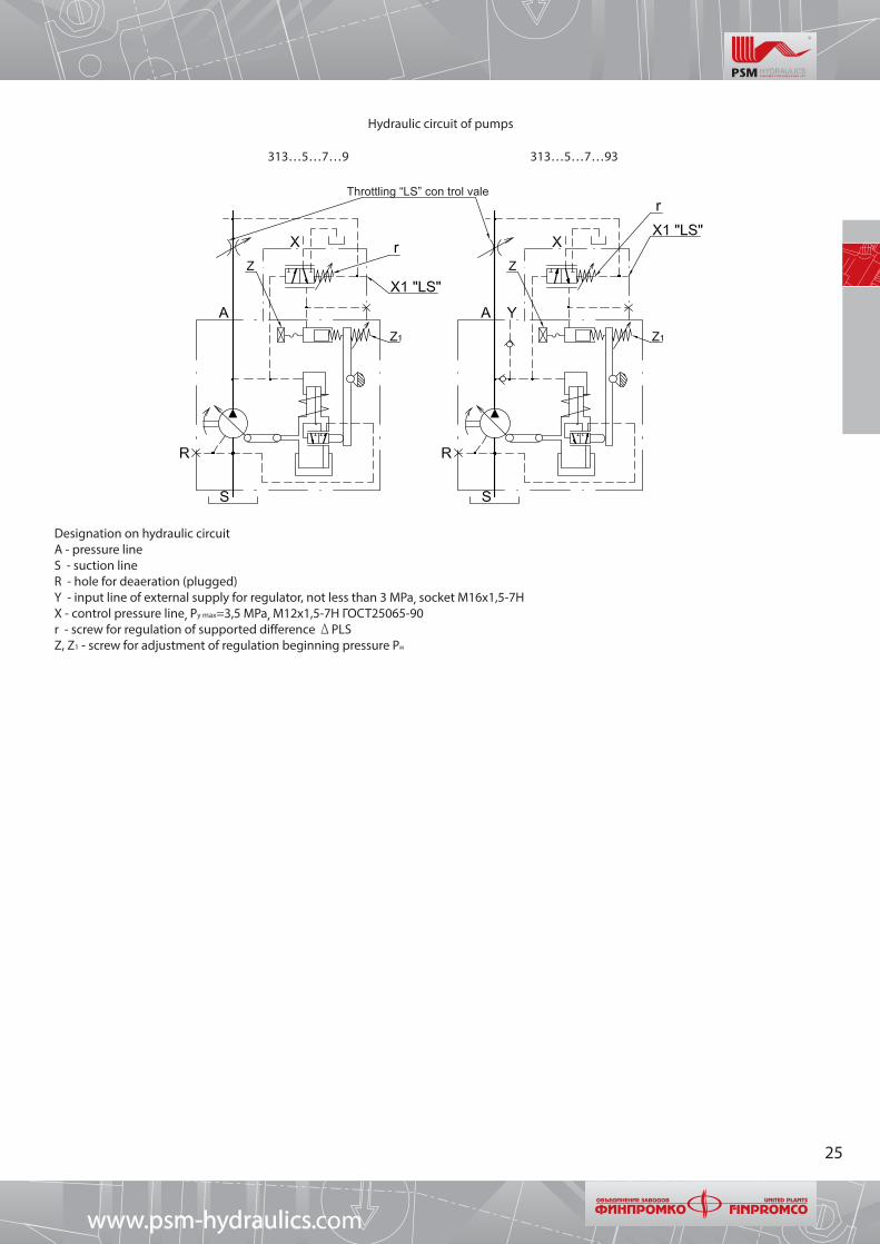
9.11 Pump with constant power regulator, with hydraulic positive control and LS in servo line(313 … 507.39).
Pump with constant power regulator, with hydraulic positive control, with LS in servo line and valve «OR» for regulator connection to servo supply (313 … 507.393)
The pump is intended for:- providing automatic support of consumed power Nп (consumed torque Мп), during pressure Р change in hydraulic system by regulation of rotary group inclination angle;- providing constant pressure difference on edge of LS control valve by regulation of feed Q at power not exceeding the adjustment of power regulator.
Pump operation While LS control valve is closed, the pump is at min working displacement Vmin, providing min feed Qmin, cient for supporting the
pressure in hydraulic system Р = 2 MPa.
RegulationAt opening of LS control valve LS the signal readjusts the pump for feed Q, providing the adjusted difference
∆РLS =1.5...2,5 MPa on edge of LS control valve.Decrease of passage section of control valve leads decrease of feed Q and consumed power Nп of pump, while increase of control valve
passage section leads increase of feed Q and consumed power Nп, to the value of power regulator adjustment value. At full opening of LS control valve, the pump achieves max feed Qmax.
Sharp tracking of LS signalis performed with pump at power not exceeding the adjustment of power regulator. As soon as the pressure of regulation beginning Рн exceeds at feed Q, the power regulator starts operating which decreases the feed Q at further increase of pressure Р in hydraulic system.
External regulation and restriction:- max rotation speed of pump shall not exceed the max allowed;- pump working displacement Vmin and Vmax, if necessary, can be limited with regulating screw;- max consumed power Nп of pump can be changed with regulation of screw Z, supported difference ∆Р can be changed with regulation of screw r.
ATTENTION:The range of regulation beginning pressure Pн=5…25 MPa. Max control pressure Ру max=3.5 MPa.While ordering a hydraulic pump specify the values of power Nдв and rotation speed nдв of drive engine or pressure of regulation
beginning Pн, min and max working displacement Vmin, Vmax.
Diagrams of dependence between consumed torque Mп, consumed power Nп and feed Q from pressure change Р
www.psm-hydraulic coms.
25
313…5…7…9 313…5…7…93
Hydraulic circuit of pumps
Designation on hydraulic circuitA - pressure lineS - suction lineR - hole for deaeration (plugged)Y - input line of external supply for regulator, not less than 3 MPa, socket М16x1,5-7HX - control pressure line, Ру max=3,5 MPa, М12х1,5-7Н ГОСТ25065-90r - screw for regulation of supported difference ΔРLSZ, Z1 - screw for adjustment of regulation beginning pressure Рн
www.psm-hydraulics.com
Throttling “LS” con trol vale

26
9.12 Pump with positive discrete electric control (313…605.303, 313…606.303)
Pump is intended for change of hydraulic pump feed Q at input and relieve of voltage Um on electromagnet.
Pump operationIn initial position when there is no voltage Um on electromagnet, the pump has min working displacement Vmin, feed Qmin and min consumed
power Nп min.
RegulationDuring the feed of voltage Um on electromagnet the pump working displacement Vg steplessly decreases leading the increase of feed Q
(consumed power Nп). Having achieved the max working displacement Vmax, the pump will have max feed Qmax and consumed power Nп.
External regulation and restriction:Feed Q (consumed power Nп), if necessary, can be restricted with one of the following ways:
- restriction of max or min working displacement Vmax or Vmin of pump;- restriction of working pressure Рmax in hydraulic system.
ATTENTION:While ordering hydraulic pumps specify the values of min and max working displacement Vmin, Vmax.
Designation on hydraulic circuitA - pressure lineS - suction lineR - hole for deaeration (plugged) Y - input line for external supply of regulator, not less than 3 MPa, socket М16x1,5-7HUm - supply voltage for electromagnet, socket as per DIN 43650А or male connector 2РМГ14Б4Ш1Е2 ГЕО.364.14ОТУ
Hydraulic circuit of pumps with positive discrete electric control
313…605.303 313…606.303
Electric circuit of connection
Connection circuitВ - switchПр - safeguardХ1 - socketЭМ - electromagnetVД1 - diod
www.psm-hydraulic coms.

27
9.13 Pump with direct shift (manual regulation) of working displacement (313…803.3, 804.3)
Pump is intended for feed regulation with direct shift of working displacement with external force.
Dependence diagram of feed Q and pressure difference Р
Hydraulic circuit of pump with direct shift (manual regulation) of working displacement
313…803.3(4) 313…804.3(4)
Designation on hydraulic circuitA - pressure lineS - suction lineR - hole for deaeration (plugged)
www.psm-hydraulics.com
28
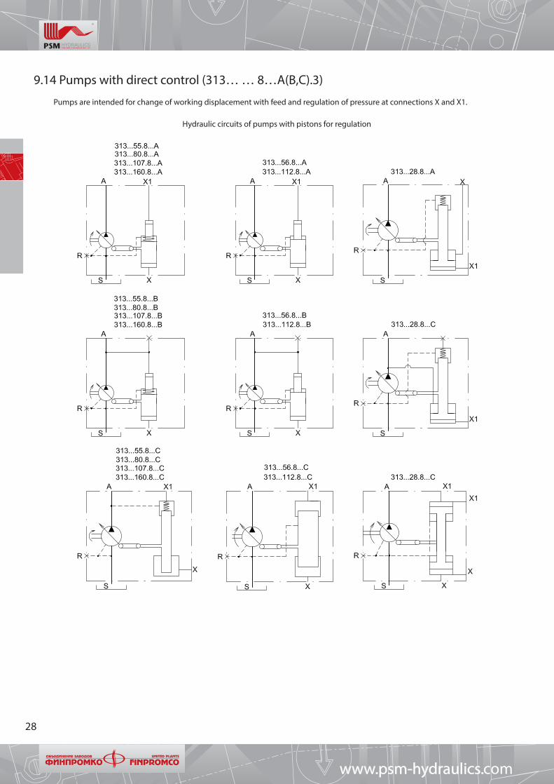
9.14 Pumps with direct control (313… … 8…А(В,С).3)
Pumps are intended for change of working displacement with feed and regulation of pressure at connections X and Х1.
Hydraulic circuits of pumps with pistons for regulation
www.psm-hydraulic coms.

29
9.15 Pump with constant pressure regulator with remote hydraulic pilot (313…80В.300П + 313.084.7020)
The pump is intended for providing the constant pressure in hydraulic system by regulation of feed Q.
Pump operationWhile pressure in hydraulic system does not exceed the pressure of regulation beginning Рн the pump is at max working displacement Vmax
and provides max feed Qmax.
RegulationAt increase of working pressure Р, starting with the pressure of regulation beginning Рн (point 1 on the Fig.), the working
displacement V starts to decrease smoothly and automatically. Having achieved the min working displacement Vmin at final pressure Р к ≈ Рн+1 (MPa), the pump feeds min flow necessary for leakage compensation Qут, providing the min consumed powerNп min (point 2).
External regulation and restriction:- max Qmax and min pump feed Qmin can be changed with regulation of screws for restriction of pump working displacement;- supported pressure Рп is changed with regulation of screw Z;- constant pressure in hydraulic system is provided by pump only within the regulation zone, that is why it is NOT RECOMMENDED to restrict the min working displacement Vmin of pump;
ATTENTION:The range of regulation beginning pressure Pн=5…35 MPa.While ordering hydraulic pumps specify the values of regulation beginning pressure Pн, of min and max working displacement
Vmin, Vmax.
Dependence diagrams of torque Mп, consumed power Nп and feed Q from pressure difference Р
Hydraulic circuit of pumps
Designation on hydraulic circuitA - pressure lineS - suction lineL - regulator drain line (connect with hydraulic tank),
М12x1,5 GOST 25065-90R - hole for deaeration (plugged)Р - working pressure line X - line for interchangeable control pressureZ - screw for regulation of supported pressure Рп
www.psm-hydraulics.com

30
Connection circuit of pumps with constant pressure regulator and remote hydraulic pilot
313.3.160.80B.300П 313.2.28.80B.300П
www.psm-hydraulic coms.
Min level of oil in tank Plug M6Plug M6
Hydraulicpilot
M12x1,5 GOST 25065
M22x1,5 GOST 25065
M18x1,5 GOST 25065M18x1,5 GOST 25065

31
10 Overall-mounting dimensions
10.1 Size range 12 cc
313.2.12.300.3
Shaft versions
Splined as per GOST 6033-80 20xf7x1.5x9g
Option G: 3,4
Keyed. Keyed as per DIN 6885 6x6x32(corresponds to GOST 23360-78)
Option G: 5, 6
Location of working channels1 flange on buttend, 1 flange sideways
Option К: 0
313.2.12.804.3 313.2.12.803.3
Connections :A - pressure lineS - suction lineR - hole for deaeration, М12x1,5 GOST 25065-90 (plugged)Z - adjusting screw Pн
L - drain line of regulator (connect with hydraulic tank),
М12x1,5 GOST 25065-90
www.psm-hydraulics.com
holes
holes
holes
holes
Right rotation Left rotation

32
10.2 Size range 28 cc
313.2.28.500.3
Shaft versions
Connections :A - pressure lineS - suction lineX - control pressure (one hole plugged) - М12x1,5 GOST 25065-90
Zo, Z и Z1 - adjusting screws Pун, Pн и Ротс. plugged in for delivery,if it is necessary to change Pун and Pн, make a request.
R - hole for deaeration (plugged), М18x1,5 GOST 25065-90L - regulator drain line (connect with hydraulic tank), М12x1,5 GOST 25065-90Um - supply voltage of electromagnet, socket as per DIN 43650А or male plug
2РМГ14Б4Ш1Е2 ГЕО.364.14ОТУХ1 - LS signal line, М12x1,5 GOST 25065-90(for hydraulic pumps with LS regulation)
Y - input line for external supply of regulator, not less than 3 MPa, socket М16x1,5-7H
Keyed. Key as per DIN 6885 8x7x40(corresponds to GOST 23360-78)
Option G: 5, 6
Splined as per GOST 6033-80 25xf7x1.5x9gOption G: 3,4
Location of working channels1 flange on buttend, 1 flange
sideways
www.psm-hydraulic coms.
Right rotation Left rotation
holes
holes
holes
holes
33
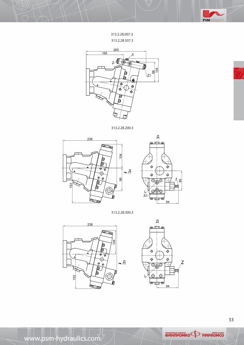
313.2.28.007.3
313.2.28.507.3
313.2.28.200.3
313.2.28.300.3
www.psm-hydraulics.com

34
313.2.28.500.32
313.2.28.502.3
313.2.28.507.38
www.psm-hydraulic coms.
35
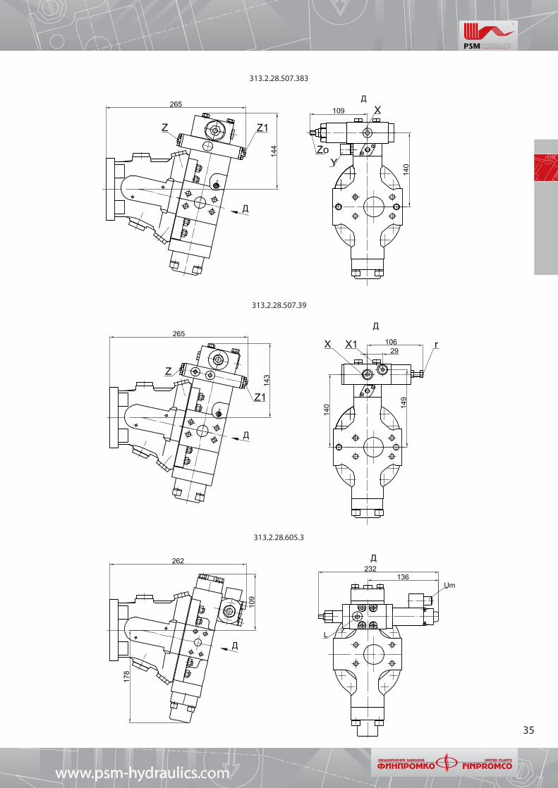
313.2.28.507.383
313.2.28.507.39
313.2.28.605.3
www.psm-hydraulics.com

36
313.2.28.803.3
313.2.28.80B.3
313.2.28.804.3
313.2.28.80C.3
www.psm-hydraulic coms.
holes
course

37
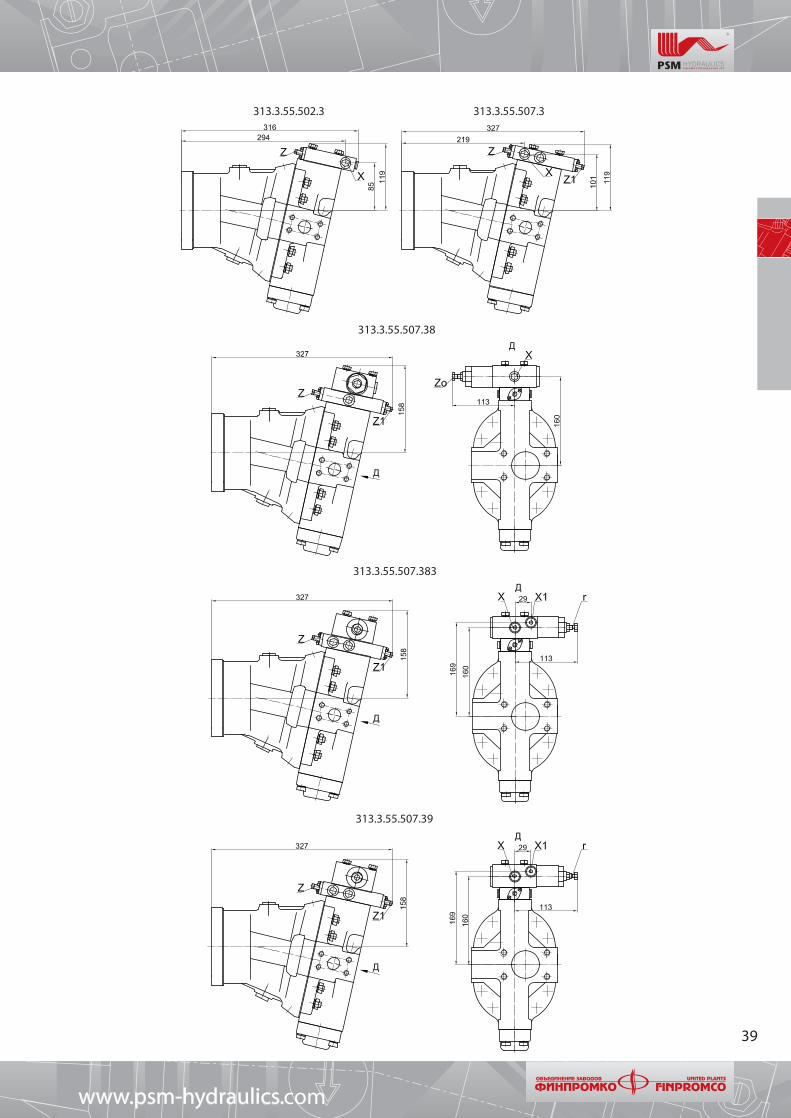
Size range 55 cc
313.3.55.500.3
Shaft versionsLocation of working channels1 flange on buttend, 1 flange
sidewaysSplined as per GOST 6033-80 35xf7x2x9g
Option G: 3,4
Splined as per DIN 5480 (GOST 23360-78)W 30х2х30х14х9g
Option G: 7, 8
Keyed. Key as per DIN 6885 8x7x50(corresponds to GOST 23360-78)
Option G: 5, 6
Connections :A - pressure lineS - suction lineX - control pressure (one hole plugged), М12x1,5 GOST 25065-90Zo, Z и Z1 - adjusting screws Pун, Pн and Ротс. are plugged in for delivery,make a request if it is required to change Pун and PнR - hole for deaeration (plugged), М18x1,5 GOST 25065-90L - regulator drain line (connect with hydraulic tank), М12x1,5 GOST 25065-90Um - supply voltage for electromagnet, socket as per DIN 43650А or male plug
2РМГ14Б4Ш1Е2 ГЕО.364.14ОТУХ1 - line for LS signal - М12x1,5 GOST 25065-90 (for hydraulic pumps with LS regulation) Y - input line for external supply of regulator, not less than 3 MPa,
socket М16x1,5-7H
www.psm-hydraulics.com
Right rotation Left rotation
holes
holes
holes
GOST

38
313.3.55.200.3
313.3.55.200.32
313.3.55.300.3
www.psm-hydraulic coms.
39
313.3.55.502.3 313.3.55.507.3
313.3.55.507.38
313.3.55.507.383
313.3.55.507.39
www.psm-hydraulics.com

40
313.3.55.80C.3
313.3.55.605.3
313.3.55.804.3
313.3.55.803.3
313.3.55.80B.3
www.psm-hydraulic coms.

41
10.4 Size range 56 cc
313.3.56.500.3
Shaft versions
Connections :A - pressure lineS - suction lineX - control pressure (one hole plugged), М12x1,5 GOST 25065-90Zo, Z and Z1 - adjusting screws of Pун, Pн and Ротс. are plugged for delivery,
make a request to change Pун and Pн
R - hole for deaeration (plugged), М18x1,5 GOST 25065-90L - regulator drain lines (connect with hydraulic tank), М12x1,5 GOST 25065-90Um - voltage supply of electromagnet, socket as per DIN 43650А or male plug
2РМГ14Б4Ш1Е2 ГЕО.364.14ОТУХ1 - LS signal line - М12x1,5 GOST 25065-90 (for hydraulic pumps with LS regulation) Y - input line for external supply of regulator, not less than 3 MPa,
socket М16x1,5-7H
Splined as per GOST 6033-80 35xf7x2x9g
Keyed. Key as per DIN 6885 8x7x50(corresponds to GOST 23360-78)
Option G: 5, 6
Splined: as per DIN 5480 (GOST 23360-78)W30х2х30х14х9g
Option G: 7, 8
Location of working channels1 flange on buttend, 1 flange
sideways
www.psm-hydraulics.com
Right rotation Left rotation
holes
holes
holes
GOST
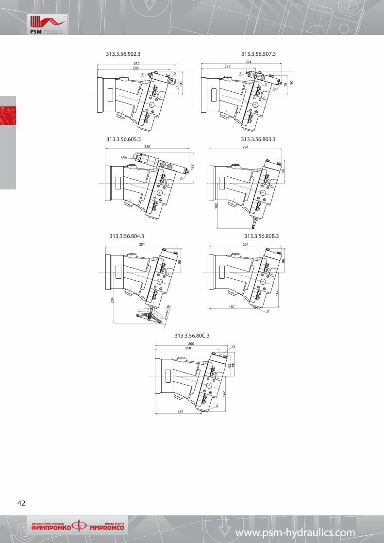
42
313.3.56.502.3
313.3.56.605.3
313.3.56.507.3
313.3.56.803.3
313.3.56.804.3 313.3.56.80B.3
313.3.56.80C.3
www.psm-hydraulic coms.
cours
e
43
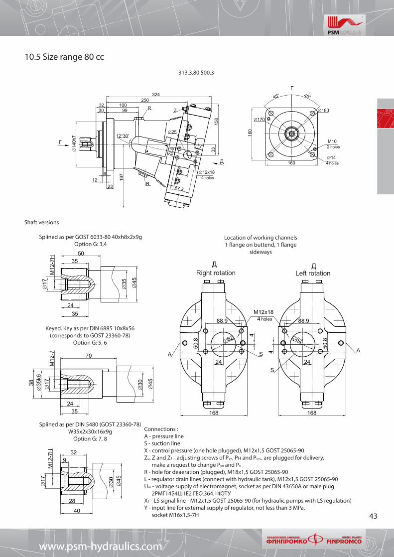
10.5 Size range 80 cc
313.3.80.500.3
Shaft versions
Location of working channels1 flange on buttend, 1 flange
sideways
Splined as per GOST 6033-80 40xh8x2x9gOption G: 3,4
Keyed. Key as per DIN 6885 10x8x56(corresponds to GOST 23360-78)
Option G: 5, 6
Splined as per DIN 5480 (GOST 23360-78)W35х2х30х16х9g
Option G: 7, 8
Connections :A - pressure lineS - suction lineX - control pressure (one hole plugged), М12x1,5 GOST 25065-90Zo, Z and Z1 - adjusting screws of Pун, Pн and Ротс. are plugged for delivery,
make a request to change Pун and Pн
R - hole for deaeration (plugged), М18x1,5 GOST 25065-90L - regulator drain lines (connect with hydraulic tank), М12x1,5 GOST 25065-90Um - voltage supply of electromagnet, socket as per DIN 43650А or male plug
2РМГ14Б4Ш1Е2 ГЕО.364.14ОТУХ1 - LS signal line - М12x1,5 GOST 25065-90 (for hydraulic pumps with LS regulation) Y - input line for external supply of regulator, not less than 3 MPa,
socket М16x1,5-7H
www.psm-hydraulics.com
Right rotation Left rotation
holes
holes
holes
holes

44
313.3.80.200.3
313.3.80.200.32
313.3.80.300.3
www.psm-hydraulic coms.

45
313.3.80.502.3
313.3.80.507.38
313.3.80.507.383
313.3.80.507.3
313.3.80.507.39
www.psm-hydraulics.com

46
313.3.80.605.303
313.3.80.803.3 313.3.80.804.3
313.3.80.80B3 313.3.80.80C.3
www.psm-hydraulic coms.
cours
e

47
10.6 Size range 107 cc
313.3.107.500.3
Shaft versionsLocation of working channels
1 flange on buttend, 1 flange sidewaysOption К: 0
Splined as per GOST 6033-80 45xh8x2x9gOption G: 3,4
Keyed. Key as per DIN 6885 12x8x63 (corresponds to GOST 23360-78)
Option G: 5, 6
Splined: as per DIN 5480 (GOST 23360-78) W40х2х30х18х9g
Option G: 7, 8 Connections :A - pressure lineS - suction lineX - control pressure (one hole plugged), М12x1,5 GOST 25065-90Zo, Z and Z1 - adjusting screws of Pун, Pн and Ротс. are plugged for delivery,
make a request to change Pун and Pн
R - hole for deaeration (plugged), М18x1,5 GOST 25065-90L - regulator drain lines (connect with hydraulic tank), М12x1,5 GOST 25065-90Um - voltage supply of electromagnet, socket as per DIN 43650А or male plug
2РМГ14Б4Ш1Е2 ГЕО.364.14ОТУХ1 - LS signal line - М12x1,5 GOST 25065-90 (for hydraulic pumps with LS regulation) Y - input line for external supply of regulator, not less than 3 MPa,socket М16x1,5-7H
www.psm-hydraulics.com
Right rotation Left rotation
holes
holes
holes
holes

48
313.3.107.200.3
313.3.107.200.32
313.3.107.300.3
www.psm-hydraulic coms.

49
313.3.107.502.3 313.3.107.507.3
313.3.107.507.38
313.3.107.607.383
313.3.107.507.39
www.psm-hydraulics.com

50
313.3.107.605.303
313.3.107.803.3 313.3.107.804.3
313.3.107.80B.3
www.psm-hydraulic coms.
cours
e

51
10.7 Size range 112 cc
313.3.112.500.3
Shaft versionsLocation of working channels
1 flange on buttend, 1 flange sidewaysOption К: 0
Connections :A - pressure lineS - suction lineX - control pressure (one hole plugged), М12x1,5 GOST 25065-90Zo, Z and Z1 - adjusting screws of Pун, Pн and Ротс. are plugged for delivery, make a request to change Pун and Pн
R - hole for deaeration (plugged), М18x1,5 GOST 25065-90L - regulator drain lines (connect with hydraulic tank), М12x1,5 GOST 25065-90Um - voltage supply of electromagnet, socket as per DIN 43650А or male plug 2РМГ14Б4Ш1Е2 ГЕО.364.14ОТУХ1 - LS signal line - М12x1,5 GOST 25065-90 (for hydraulic pumps with LS regulation) Y - input line for external supply of regulator, not less than 3 MPa,socket М16x1,5-7H
Splined as per GOST 6033-80 45xh8x2x9gOption G: 3,4
Keyed. Key as per DIN 6885 12x8x63 (corresponds to GOST 23360-78)
Option G: 5, 6
Splined: as per DIN 5480 (GOST 23360-78) W40х2х30х18х9g
Option G: 7, 8
www.psm-hydraulics.com
Right rotation Left rotation
holes
holes
holes
holes

52
313.3.112.605.303
313.3.112.502.3 313.3.112.507.3
313.3.112.803.3 313.3.112.804.3
313.3.112.80B.3 313.3.112.80C.3
www.psm-hydraulic coms.
cours
e

53
10.8 Size range 160 cc
313.3.160.500.3
Shaft versionsLocation of working channels 1 flange on buttend, 1 flange
sideways
Connections :A - pressure lineS - suction lineX - control pressure (one hole plugged), М12x1,5 GOST 25065-90Zo, Z and Z1 - adjusting screws of Pун, Pн and Ротс. are plugged for delivery,
make a request to change Pун and Pн
R - hole for deaeration (plugged), М18x1,5 GOST 25065-90L - regulator drain lines (connect with hydraulic tank), М12x1,5 GOST 25065-90Um - voltage supply of electromagnet, socket as per DIN 43650А or male plug
2РМГ14Б4Ш1Е2 ГЕО.364.14ОТУХ1 - LS signal line - М12x1,5 GOST 25065-90 (for hydraulic pumps with LS regulation) Y - input line for external supply of regulator, not less than 3 MPa,
socket М16x1,5-7H
Splined as per GOST 6033-80 45xh8x2x9gOption G: 3,4
Keyed. Key as per DIN 6885 12x8x63 (corresponds to GOST 23360-78)
Option G: 5, 6
Splined: as per DIN 5480 (GOST 23360-78) W40х2х30х18х9g
Option G: 7, 8
www.psm-hydraulics.com
Right rotation Left rotation
holes
holes
holes
holes

54
313.3.160.200.3
313.3.160.200.32
313.3.160.300.3
www.psm-hydraulic coms.

55
313.3.160.502.3 313.3.160.507.3
313.3.160.507.38
313.3.160.507.383
313.3.160.507.39
www.psm-hydraulics.com

56
313.3.160.605.303
313.3.160.803.3 313.3.160.804.3
313.3.160.80B.3 313.3.160.80C.3
www.psm-hydraulic coms.

57
10.9 Size range 250 cc
313.3.250.500.3
Shaft versionsLocation of working channels
1 flange on buttend, 1 flange sidewaysOption К: 0
Connections :A - pressure lineS - suction lineX - control pressure (one hole plugged), М12x1,5 GOST 25065-90Zo, Z and Z1 - adjusting screws of Pун, Pн and Ротс. are plugged for delivery,
make a request to change Pун and Pн
R - hole for deaeration (plugged), М18x1,5 GOST 25065-90L - regulator drain lines (connect with hydraulic tank), М12x1,5 GOST 25065-90Um - voltage supply of electromagnet, socket as per DIN 43650А or male plug
2РМГ14Б4Ш1Е2 ГЕО.364.14ОТУХ1 - LS signal line - М12x1,5 GOST 25065-90 (for hydraulic pumps with LS regulation) Y - input line for external supply of regulator, not less than 3 MPa,
Splined as per GOST 6033-80 45xh8x2x9gOption G: 3,4
Keyed. Key as per DIN 6885 12x8x63 (corresponds to GOST 23360-78)
Option G: 5, 6
Splined: as per DIN 5480 (GOST 23360-78) W40х2х30х18х9g
Option G: 7, 8
www.psm-hydraulics.com
Right rotation Left rotation
holes
holes
holes

58
313.3.250.200.3
313.3.250.200.32
313.3.250.300.3
www.psm-hydraulic coms.

59
313.3.250.502.3 313.3.250.507.3
313.3.250.507.38
313.3.250.507.383
313.3.250.507.39
www.psm-hydraulics.com

60
313.3.250.605.303
313.3.250.804.3 313.3.250.80B.3
313.3.250.80C.3
www.psm-hydraulic coms.

61
11. Recommendations for installation
For proper operation of hydraulic pumps 313 series it is necessary to observe the requirements of the present Section.
Connection of hydraulic pump shaft with shaft of driven device shall be performed though flexible coupling. The coupling (gear or pulley) shall be set only with the help of bolt or threaded hole in drive shaft. It is prohibited to screw the coupling with impacts. After axial tightening and bolt locking observe the dimensions given on the Fig.
Usage of other types device conveying the torque is allowed after negotiations with the manufacturer.
During the mounting of hydraulic pump observe the following requirements:–shifting of axes connecting the shafts – 0,1 mm, not more;–non flatness of mounting surfaces – 0,03 mm, not more;–roughness of mounting surface – Ra≤2,5 mkm;–observe ultimate axial and radial loads on shaft (see Section 8), the choice of optimal angle for installation of gear drive according to Section 8.
At open mounting of shaft the additional protection of gasket sealing is required against any contamination.
The pump can be mounted in any position but shall be lower than the lowest level of oil in the tank according to versions given on the Fig.
PROHIBITED to connect the drain pipe during the pump operation in open circuit hydraulic systems.Allowed to mount hydraulic pump directly to the tank with working fluid. At such installation it is necessary to specify the required version
of hydraulic pump with index «П» (submersible) at the end of designation. Hydraulic pump must be installed according to the Fig.. During the mounting deaerate through hole R (М6), after that install the plug on its place. If max level of oil in the tank is on the same level with min level of oil in the tank, it is allowed not to install plug М6 in order to prevent the air lock.
Before the launch check reliability of pump mount on the main unit, tighten the mounting bolts.
www.psm-hydraulics.com
Plug M6
Bolt
Min level of oil in tankPlug M6

62
Notes
www.psm-hydraulic coms.
63
www.psm-hydraulics.com
8 E, 1st km, Sibirsky trakt, Ekaterinburg, Russia, P.C. 620100Tel.: +7 343 2299544, fax: +7 343 2646699
www.psm-hydraulics.com e-mail: [email protected]
International Trade Director:Azat ABDRAKHMANOVTel.: +7 343 2612075Fax: +7 343 2646666E-mail: [email protected]
Sales ManagerTaissia ZubovaTel: +7 343 2646650, +7 343 2299602 E-mail: [email protected]
“Pnevmostroimashina” JSC