Embed Size (px)
Citation preview

SAVE THESE INSTRUCTIONS
3-Wire Deep Well Submersible Pump
Owner’s Manual
WARNING: Read carefully and understand all ASSEMBLY AND OPERATION
INSTRUCTIONS before operating. Failure to follow the safety rules and other basic safety
precautions may result in serious personal injury.
Item #52609, #52610, #52612, #52615

Page 2 of 17
Thank you very much for choosing a Powerhorse™ product!
For future reference, please complete the owner’s record below:
Serial Number/Lot Date Code: ________________________________
Purchase Date: ____________________________________________
Save the receipt, warranty, and this manual. It is important that you read
the entire manual to become familiar with this product before you begin
using it.
This Deep Well Submersible Pump is designed for certain applications
only. Northern Tool & Equipment is not responsible for issues arising
from modification or improper use of this product such as an application
for which it was not designed. We strongly recommend that this product
not be modified and/or used for any application other than that for which
it was designed.
For technical questions, please call 1-800-222-5381.

Page 3 of 17
Table of Contents
Intended Use .......................................................................................................................................... 4
Technical Specifications ...................................................................................................................... 4
Important Safety Information ............................................................................................................... 4
Specific Operation Warnings ............................................................................................................... 6
Grounding .............................................................................................................................................. 7
Installation Instructions ........................................................................................................................ 7
Connecting to Water Tank .................................................................................................................. 13
Troubleshooting .................................................................................................................................. 14
Replacement Parts .............................................................................................................................. 15
Limited Warranty ................................................................................................................................. 16

Page 4 of 17
Intended Use
The Powerhouse 3-Wire Deep Well Submersible Pump is designed to supply water at the required
pressure with high efficiency and a long service life. The pump features energy-efficient operation and
is designed for use in wells with inside diameters of at least 4 inches.
Very Important: This item is not certified for use with potable water systems. These pumps are
intended for agriculture and grey water applications. Please consult a licensed plumbing contractor
before using in residential water systems.
Technical Specifications
All wiring must meet the National Electrical Code or Canadian Electrical Code requirements, as well
as local code requirements. Use only copper wiring for connections to the pump and control box.
Wiring Connections
Item HP Volts Fuse Size
Standard Dual Elem
#52609 1/2 230 20 10
#52610 3/4 230 25 5
#52612 1 230 30 20
#52615 1 230 30 20
Important Safety Information
⚠WARNING
Read and understand all instructions. Failure to follow all instructions may result in serious injury
or property damage.
The warnings, cautions, and instructions in this manual cannot cover all possible conditions or
situations that could occur. Exercise common sense and caution when using this pump. Always
be aware of the environment and ensure that the tool is used in a safe and responsible manner.
Do not allow persons to operate or assemble the product until they have read this manual and
have developed a thorough understanding of how it works.
Do not modify this pump in any way. Unauthorized modification may impair the function and/or
safety and could affect the life of the product. There are specific applications for which the product
was designed.
Use the right tool for the job. DO NOT attempt to force small equipment to do the work of larger
industrial equipment. There are certain applications for which this equipment was designed.
Products are safer and do a better job at the capacity for which it was intended. DO NOT use this
equipment for a purpose for which it was not intended.
Industrial or commercial applications must follow OSHA requirements.
⚠WARNING
WORK AREA SAFETY
Inspect the work area before each use. Keep work area clean, dry, free of clutter, and well lit.
Cluttered, wet, or dark work areas can result in injury. Using the deep well submersible pumps in
confined work areas may put you dangerously close to other cutting tools and rotating parts.

Page 5 of 17
Do not use the product where there is a risk of causing a fire or an explosion; e.g., in the
presence of flammable liquids, gases, or dust. The product can create sparks, which may ignite
the flammable liquids, gases, or dust.
Do not allow the deep well submersible pumps to come into contact with an electrical source. The
tool is not insulated and contact will cause electrical shock.
Keep children and bystanders away from the work area while operating the tool. Do not allow
children to handle the deep well submersible pumps.
Be aware of all power lines, electrical circuits, water pipes, and other mechanical hazards in your
work area. Some of these hazards may be hidden from your view and may cause personal injury
and/or property damage if contacted.
⚠WARNING
PERSONAL SAFETY
Stay alert, watch what you are doing, and use common sense when operating the pump. Do not
use the tool while you are tired or under the influence of drugs, alcohol, or medication. A moment
of inattention while operating the tool may result in serious personal injury.
Dress properly. Do not wear loose clothing, dangling objects, or jewelry. Keep your hair, clothing
and gloves away from moving parts. Loose clothes, jewelry, or long hair can be caught in moving
parts. Air vents on the tool often cover moving parts and should be avoided.
Wear the proper personal protective equipment when necessary. Use ANSIZ87.1 compliant
safety goggles (not safety glasses) with side shields, or when needed, a face shield. Use a dust
mask in dusty work conditions. Also use non-skid safety shoes, hardhat, gloves, dust collection
systems, and hearing protection when appropriate. This applies to all persons in the work area.
Do not overreach. Keep proper footing and balance at all times.
Ensure the power switch is off prior to move the pump.
⚠WARNING
ELECTRICAL SAFETY
Permanently ground pump, motor and control box before connecting power cable to power
supply. Connect ground wire to approved ground first, and then connect to equipment being
installed
Motor is supplied with copper grounding wire. Splice wire to copper conductor that matches wire.
See page 7 for splicing instructions.
Do not allow the product to come into contact with an electrical source. The tool is not insulated
and contact will cause electrical shock.
Avoid body contact with grounded surfaces such as pipes, radiators, ranges, and refrigerators.
There is an increased risk of electric shock if your body is grounded.
Do not expose the control box to rain or wet conditions. Water entering the control box will
increase the risk of electric shock.
Do not ground to gas line. Fire, explosion, and serious injury could result.
Use only copper wiring for connections to pump and control box.

Page 6 of 17
⚠CAUTION
PUMP USE AND CARE
Do not force the pump. Products are safer and do a better job when used in the manner for which
they are designed. Plan your work, and use the correct product for the job.
Check for damaged parts before each use. Carefully check that the deep well submersible pump
will operate properly and perform its intended function. Replace damaged or worn parts
immediately. Never operate the deep well submersible pump with a damaged part.
Disconnect the power from the pump and place the switch in the locked or off position before
making any adjustments, changing accessories, or storing the tool. Such preventive safety
measures reduce the risk of starting the tool accidentally.
Use only accessories that are recommended by the manufacturer for use with your deep well
submersible pump Accessories that may be suitable for one product may create a risk of injury
when used with another tool. Never use an accessory that has a lower operating speed or
operating pressure than the tool itself.
Keep guards in place and in working order. Never operate the product without the guards in place.
Specific Operation Warnings
⚠WARNING
ELECTRIC SHOCK HAZARD
Ensure all metal parts including the pump housing, control enclosures, metal plumbing and any
other metal near the pump or cable are properly grounded.
Disconnect power before servicing the pump or working around the pump.
Intended for pure water only. Not for use in pools or for pumping chemicals.
Do not lift the pump by or pull on the cord.
Never run the pump dry.
Installation must be performed by a qualified electrician.
Ensure the pump and all metal near the pump is properly grounded.
Not for use by or around children.
Fully read and understand the instructions on this unit and in the manual before use.
Keep the manual for future references. Replace worn labels.
⚠CAUTION
This pump has been evaluated for use with water only.
Do not run dry.
Risk of electric shock – this pump has not been investigated for use in swimming pools or marine
areas. To reduce the risk of electric shock, see instruction manual for proper installation. Install
only on a circuit protected by a ground-fault circuit interrupter (GFCI).
Thermally protected, enclosure type 3.

Page 7 of 17
Grounding
Note: Power supply wire (cable) length in feet.
Cable Size
Volts HP 14 12 10 8 6 4 3 2 1 0
230 1/2 400 650 1020 1610 2510 3880 4810 5880 7170 8720
230 3/4 300 480 760 1200 1870 2890 3580 4370 5330 6470
230 1 250 400 630 990 1540 2380 2960 3610 4410 5360
230 1 250 400 630 990 1540 2380 2960 3610 4410 5360
Installation Instructions
Install for the Wire Splicing
Splice the wire to the motor leads. Use only copper wire for connections to the pump/motor assembly
and control box.
Heat Shrink & Splice Instructions
(wire sizes No. 14, 12 and 10 AWG [2, 3 and 5mm2]):
1. Remove 3/8" (9.5 mm) of the insulation from the ends of the motor leads and power supply
wires.
2. Place the heat shrink tubing over the motor leads. Position the tubing between the power supply
and the motor.
3. Match the supply wire colors with the colors of the motor leads.
4. Insert the supply wire and lead ends into the butt connector and crimp (see Figure 2 and 3).
Match the colors of the supply wires with the colors of the motor leads. Check the lead
connections by gently pulling on them.
5. Center the tubing over the butt connector and apply heat evenly with the torch (a match or
lighter will not supply enough heat).
Note: Keep the torch moving. Too much concentrated heat may damage the tubing (see Figure 4).

Page 8 of 17
Instructions for Mechanical Splice Kit with Plastic Insulators
(wire sizes 14, 12, and 10 AWG [2, 3, and 5 mm2])
1. With a wire cutting tool, cut off the motor leads. Stagger the lead and wire length so that the
second lead is 4" (101.6 mm) longer than first lead and the third lead is 4" (101.6 mm) longer
than the second.
2. With the wire cutting tool, cut off the wire ends. Match the colors and the lengths of the wires
between the power supply and the motor.
3. With the wire stripping tool, trim the insulation back 1/2" (12.7 mm) from the power supply wire
and the motor lead ends.
4. Unscrew the plastic caps from the insulators. Place a cap and neoprene gasket sleeve on each
wire to be spliced (see Figure 5).
5. Slide the insulator body onto one wire end (Figure 5).

Page 9 of 17
6. Insert the wire end into the butt connector and crimp. Match the wire colors between the power
supply and the motor (see Figure 6).
7. Center the insulator body over the splice and slide the gasket sleeves into the body as far as
they will go. Screw the caps onto the insulator body (Figure 7) and tighten them by hand for a
strong, waterproof splice.
Control box Installation Connection Diagram

Page 10 of 17
Power Supply Wire Installation
1. To test the pump, connect it to the proper power supply for a short amount of time (no more than
30 seconds). The power supply frequency and voltage must be within 10% of frequency and the
voltage shown on the product nameplate.
2. Fasten the power supply wire leads to the pump discharge block. Then fasten the leads to the
plastic pipe within 6" (150mm) of the discharge block. Use the centering guides to prevent the
wire and pipe from rubbing the well casing.
3. Connect the copper grounding wire to the motor bracket. The grounding wire must have a
diameter of at least that of the wires supplying the current to the motor. Consult the National
Electrical Code or Canadian Electrical Code, as well as the local code, for grounding information
and safety guidelines.
4. Use only submersible power supply wires supplied by a pump manufacturer. When lowering the
pump into the well, secure the supply wires to the discharge pipe at 10 ft. (3.1 m) intervals with
Scotch® #33 electrical tape. Be careful not to damage the pump wires.
Note: To avoid dropping the pump down the well or damaging the wires or splices, NEVER allow the
pump wires to support the weight of the pump.
Pump Installation
1. If a standard air-over-water pressure tank is used, install two bleeder orifices about 2 ft. (0.6 m)
apart as shown in Figure 10. Orifices will automatically charge the tank with air. See Figure 10 to
help determine orifice location.
Note: If a precharged tank is used, DO NOT install bleeder orifices. If the pump and pre-charged tank
are replacing a standard tank system, remove bleeder orifices before installing the pump in the well.
2. To prevent losing the pump down the well, connect a safety rope strong enough to support the
pump and drop the pipe (minimum 5/16" [8 mm] twisted polypropylene or pronila rope) to the
eyelet on the pump discharge. Tie off the other end of the safety rope securely to the well seal,
well cap, or pitless adapter.
3. Install piping based on these guidelines: For installations up to 100’ (30.5 m) in depth, use 100
psi (689.5 kPa) rated polyethylene plastic pipe. For installations up to 220’ (67.1 m) in depth, use
160 psi (1103.2 kPa) rated polyethylene plastic. For depths beyond 220’ (67.1 m), use
galvanized steel pipe for the entire drop pipe.
Initial Start-Up/New Wells
Note: Never operate the pump with the discharge valve completely closed. This can cause significant
pump damage and will void the warranty.
Note: To prevent sand locking the pump, follow this procedure when starting the pump for the first
time. Do not start the pump with the discharge valve completely open unless you have followed this
procedure first.
1. Connect a pipe elbow, a short length of pipe, and a gate valve to the pump discharge (at well
head).
2. Mount the motor control box (for a 3- wire pump) or fused disconnect switch (for a 2-wire pump)
in a permanently weatherproof place. Make sure that controls will not be subjected to extreme
heat or excess moisture.
3. Make sure controls are in OFF position.
4. Connect the motor leads and power supply to the motor control box or magnetic starter (see
Installation Wiring Diagrams). Do not start the pump yet.
5. Open the gate valve on discharge one third of the way. Start the pump (see Figure 8).

Page 11 of 17
6. Let the water run until it is clear. (To check solids in water, fill a container with water from the pump. If any solids settle after a minute, continue running the pump.)
Power Supply Wire Installation
1. To test the pump, connect it to a proper power supply for a short amount of time (no more than
30 seconds). The power supply frequency and voltage must be within 10% of frequency and the
voltage shown on the product nameplate.
2. Fasten the power supply wire leads to the pump discharge block. Then fasten the leads to the
plastic pipe within 6" (150 mm) of the discharge block. Use centering guides to prevent wire and
pipe from rubbing well casing.
3. Connect copper grounding wire to motor bracket. Grounding wire must have a diameter at least
that of wires supplying current to motor. Consult National Electrical Code or Canadian Electrical
Code, as well as local code, for grounding information and safety guidelines.
4. Use only submersible power supply wires supplied by the pump manufacturer. When lowering
the pump into the well, secure the supply wires to discharge the pipe at 10 ft. (3.1 m) intervals
with Scotch® #33 electrical tape. Take care not to damage the pump wires.
Note: To avoid dropping the pump down the well or damaging wires or splices, NEVER allow the
pump wires to support the weight of the pump.
Pump Installation
1. If the standard air-over-water pressure tank is used, install two bleeder orifices about 2 ft. (0.6
m) apart as shown in Figure 12. Orifices will automatically charge the tank with air. See Figure
12 to help determine orifice location.
Note: If a precharged tank is used, DO NOT install bleeder orifices. If a pump and pre-charged tank
are replacing a standard tank system, remove the bleeder orifices before installing the pump in the
well.
2. To prevent losing the pump down the well, connect a safety rope strong enough to support the
pump and drop the pipe (minimum 5/16" [8 mm] twisted polypropylene or pronila rope) to the
eyelet on the pump discharge. Tie off the other end of the safety rope securely to the well seal,
well cap, or pitless adapter.
Page 12 of 17
3. Install piping based on these guidelines:
For installations up to 100’ (30.5 m) in depth, use 100 psi (689.5 kPa) rated polyethylene plastic pipe.
For installations up to 220’ (67.1 m) in depth, use 160 psi (1103.2 kPa) rated polyethylene plastic.
For depths beyond 220’ (67.1 m), use galvanized steel pipe for the entire drop pipe.
Initial Start-Up/New Wells
Note: Never operate the pump with the discharge valve completely closed. This can cause significant
pump damage and will void the warranty.
Note: To prevent sand-locking the pump, follow this procedure when starting the pump for the first
time. Do not start the pump with the discharge valve completely open until you have followed this
procedure:
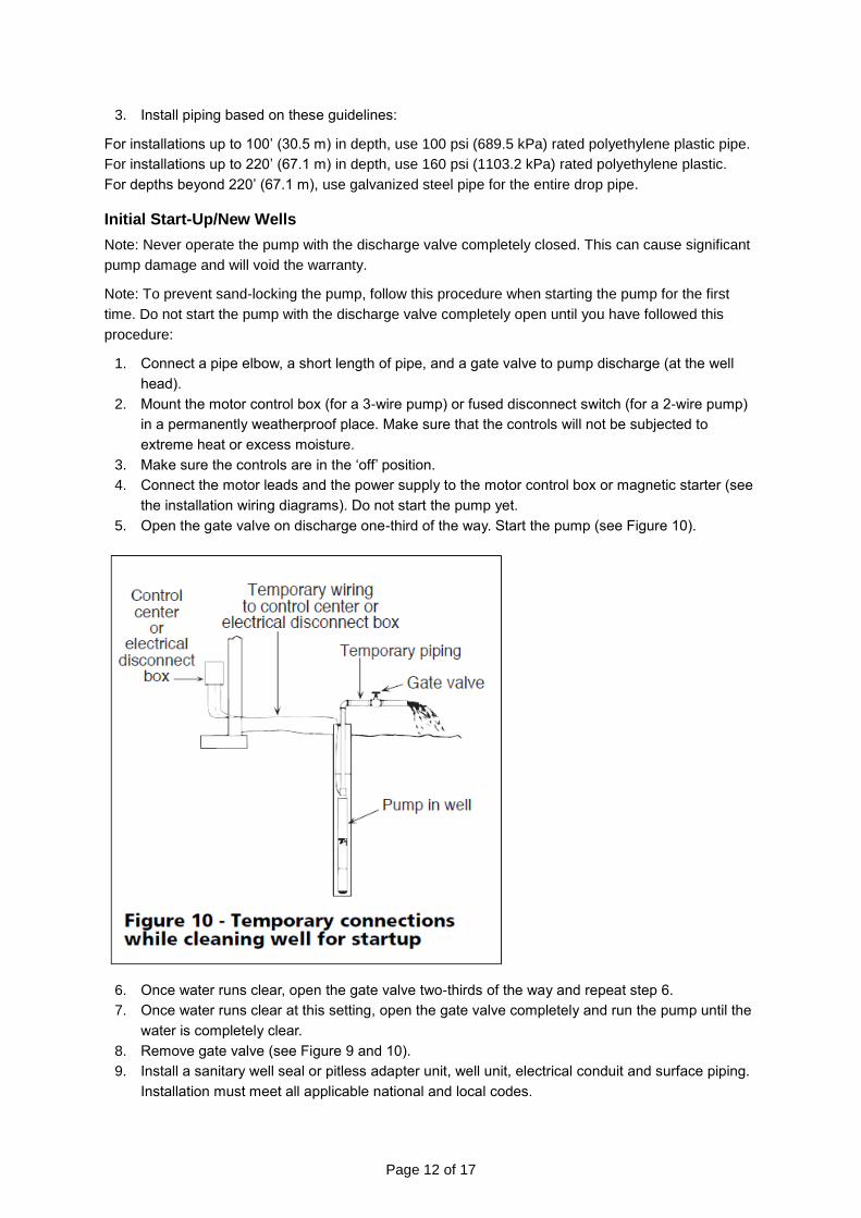
1. Connect a pipe elbow, a short length of pipe, and a gate valve to pump discharge (at the well
head).
2. Mount the motor control box (for a 3-wire pump) or fused disconnect switch (for a 2-wire pump)
in a permanently weatherproof place. Make sure that the controls will not be subjected to
extreme heat or excess moisture.
3. Make sure the controls are in the ‘off’ position.
4. Connect the motor leads and the power supply to the motor control box or magnetic starter (see
the installation wiring diagrams). Do not start the pump yet.
5. Open the gate valve on discharge one-third of the way. Start the pump (see Figure 10).
6. Once water runs clear, open the gate valve two-thirds of the way and repeat step 6.
7. Once water runs clear at this setting, open the gate valve completely and run the pump until the
water is completely clear.
8. Remove gate valve (see Figure 9 and 10).
9. Install a sanitary well seal or pitless adapter unit, well unit, electrical conduit and surface piping.
Installation must meet all applicable national and local codes.

Page 13 of 17
Connecting to Water Tank
⚠WARNING
High pressure and tank explosion hazard! To prevent over-pressurization, install a pressure relief
valve capable of releasing pump air flow at 75 psi (517.1 kPa) when using an air-over-water
pressure tank. When using a precharged pressure tank, install a pressure relief valve that will
release the entire air flow at 100 psi (690 kPa). Install this valve between pump and tank.
Note: Use only Teflon® tape on joints in a plastic pipe. A pipe joint compound can cause cracking in
plastics.
Do not allow the pump or piping system to freeze. Failure to do so could result in serious damage to
equipment and will void the warranty.
Note: Do not allow the pump or piping system to freeze. Failure to do so could result in serious
damage to equipment and will void the warranty.
Connecting to the Tank/ Water System
See Figure 9 for an illustration of the piping connections to pre-charged pressure tanks.
Before starting the pump, check to make sure that pre-charged air pressure is 2 psi (13.8 kPa) below
pump cut-in setting. (For example, in a tank used with a 30-50 psi pressure switch, the pre-charged
pressure should be 28 psi [193.1 kPa].) Adjust pressure by adding or releasing air from the tire valve
located on top of tank. Check precharged pressure annually and adjust as needed.
Standard Tank Hook-Up
See Figure 10 for an illustration of the piping connections to standard pressure tank as well as the

Page 14 of 17
distance between the air release ports and the tank.
Troubleshooting
Use the table below to troubleshoot problems before contacting service personnel or your local
dealer. If the problem continues after troubleshooting, call your local dealer for assistance.
Failure Possible Cause Corrective Action
Motor will not start but fuses are not blown.
No voltage at control box or a disconnected switch.
Install correct fuse or time delay fuse.
No voltage at pressure switch. Replace faulty pressure switch.
No voltage at control box. Rewire supply to control box.
Control box is incorrectly wired. Reconnect the control box correctly.
Fuses blow or overload protector trips when motor starts.
Wrong size fuse or wrong size time delay fuse.
Install fuse or time delay fuse of correct size.
Wire size too small. Install wire of correct size.
Start capacitor defective, blown, or wrong size.
Start capacitor defective, blown, or wrong size.
Low or high voltage. If voltage variation is greater than 10% of nameplate rating, call power company or water supply to adjust voltage.
Fuses blow or
overload protector
trips when motor
starts.
Power supply wire leads not properly connected to control box.
Reconnect leads to match wiring diagram in control box cover. Reconnect power supply wires so wire color code matches motor lead color code.
Broken wire in control box. Disconnect power. Repair or replace defective wire.
Pump or motor stuck or binding.
Make all possible aboveground checks. If necessary, pull pump. If pump is locked, replace it. Clean well of all sand and lime before reinstalling pump.
Wire splices for power supply or motor leads grounded, shorted, or open.
Consult licensed electrician or qualified serviceperson. Do not attempt to disassemble pump or motor.
Fuses blow or overload protector
Low or high voltage. If voltage variation is greater than 10% of nameplate rating, call power company to
Page 15 of 17
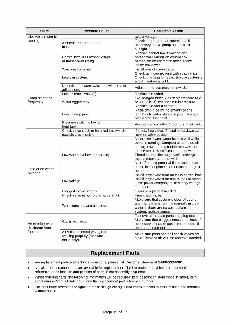
Failure Possible Cause Corrective Action
trips while motor is running
adjust voltage.
Ambient temperature too high.
Check temperature of control box. If necessary, move pump out of direct sunlight.
Control box uses wrong voltage or horsepower rating.
Replace control box if voltage and horsepower ratings on control box nameplate do not match those shown inside box cover.
Wire size too small. Install wire of correct size.
Pump starts too frequently
Leaks in system. Check tank connections with soapy water. Check plumbing for leaks. Ensure system is airtight and watertight.
Defective pressure switch or switch out of adjustment.
Adjust or replace pressure switch.
Leak in check valve(s). Replace if needed.
Waterlogged tank. Pre-charged tanks: Adjust air pressure to 2 psi (13.8 kPa) less than cut-in pressure. Replace bladder if needed.
Leak in drop pipe. Raise drop pipe by increments of one length until water stands in pipe. Replace pipe above that point.
Pressure switch is too far from tank.
Position switch within 1 foot (0.3 m) of tank.
Little or no water pumped
Check valve stuck or installed backwards (standard tank only).
If stuck, free valve. If installed backwards, reverse valve position.
Low water level (water source).
Determine lowest water level in well while pump is running. Compare to pump depth setting. Lower pump further into well, but at least 5 feet (1.5 m) from bottom of well. Throttle pump discharge until discharge equals recovery rate of well. Note: Running pump while air locked can cause loss of prime and serious damage to pump.
Low voltage.
Install larger wire from meter to control box. Install larger wire from control box to pump. Have power company raise supply voltage if needed.
Clogged intake screen. Clean or replace if needed.
Check valve at pump discharge stuck. Free check valve.
Worn impellers and diffusers.
Make sure that system is clear of debris and that pump is running normally in clear water. If there are no obstructions in system, replace pump.
Air or milky water discharge from faucets
Gas in well water.
Remove air release ports and plug tees. Make sure that plugged tees do not leak. If necessary, separate gas from air before it enters pressure tank.
Air volume control (AVC) not working properly (standard tanks only).
Make sure ports and ball check valves are clear. Replace air volume control if needed.
Replacement Parts
For replacement parts and technical questions, please call Customer Service at 1-800-222-5381.
Not all product components are available for replacement. The illustrations provided are a convenient reference to the location and position of parts in the assembly sequence.
When ordering parts, the following information will be required: item description, item model number, item serial number/item lot date code, and the replacement part reference number.
The distributor reserves the rights to make design changes and improvements to product lines and manuals without notice.

Page 16 of 17
Limited Warranty
Northern Tool and Equipment Company, Inc. ("We'' or "Us'') warrants to the original purchaser only
("You'' or “Your”) that the Powerhorse product purchased will be free from material defects in both
materials and workmanship, normal wear and tear excepted, for a period of one year from date of
purchase. The foregoing warranty is valid only if the installation and use of the product is strictly in
accordance with product instructions. There are no other warranties, express or implied, including the
warranty of merchantability or fitness for a particular purpose. If the product does not comply with this
limited warranty, Your sole and exclusive remedy is that We will, at our sole option and within a
commercially reasonable time, either replace the product or product component without charge to You
or refund the purchase price (less shipping). This limited warranty is not transferable.
Limitations on the Warranty
This limited warranty does not cover: (a) normal wear and tear; (b) damage through abuse, neglect,
misuse, or as a result of any accident or in any other manner; (c) damage from misapplication,
overloading, or improper installation; (d) improper maintenance and repair; and (e) product alteration
in any manner by anyone other than Us, with the sole exception of alterations made pursuant to
product instructions and in a workmanlike manner.
Obligations of Purchaser
You must retain Your product purchase receipt to verify date of purchase and that You are the original
purchaser. To make a warranty claim, contact Us at 1-800-222-5381, identify the product by make
and model number, and follow the claim instructions that will be provided. The product and the
purchase receipt must be provided to Us in order to process Your warranty claim. Any returned
product that is replaced or refunded by Us becomes our property. You will be responsible for return
shipping costs or costs related to Your return visit to a retail store.
Remedy Limits
Product replacement or a refund of the purchase price is Your sole remedy under this limited warranty
or any other warranty related to the product. We shall not be liable for: service or labor charges or
damage to Your property incurred in removing or replacing the product; any damages, including,
without limitation, damages to tangible personal property or personal injury, related to Your improper
use, installation, or maintenance of the product or product component; or any indirect, incidental or
consequential damages of any kind for any reason.
Assumption of Risk
You acknowledge and agree that any use of the product for any purpose other than the specified
use(s) stated in the product instructions is at Your own risk.
Governing Law
This limited warranty gives You specific legal rights, and You also may have other rights which vary
from state to state. Some states do not allow limitations or exclusions on implied warranties or
incidental or consequential damages, so the above limitations may not apply to You. This limited
warranty is governed by the laws of the State of Minnesota, without regard to rules pertaining to
conflicts of law. The state courts located in Dakota County, Minnesota shall have exclusive jurisdiction
for any disputes relating to this warranty.

Page 17 of 17
Distributed by:
Northern Tool & Equipment Company, Inc.
Burnsville, Minnesota 55306
www.northerntool.com
Made in China