Embed Size (px)
Citation preview
Copyright © 2005 Juniper Networks, Inc. Proprietary and Confidential www.juniper.net
4-1
Virtual Chassis
© 2008 Juniper Networks, Inc. All rights reserved. 2
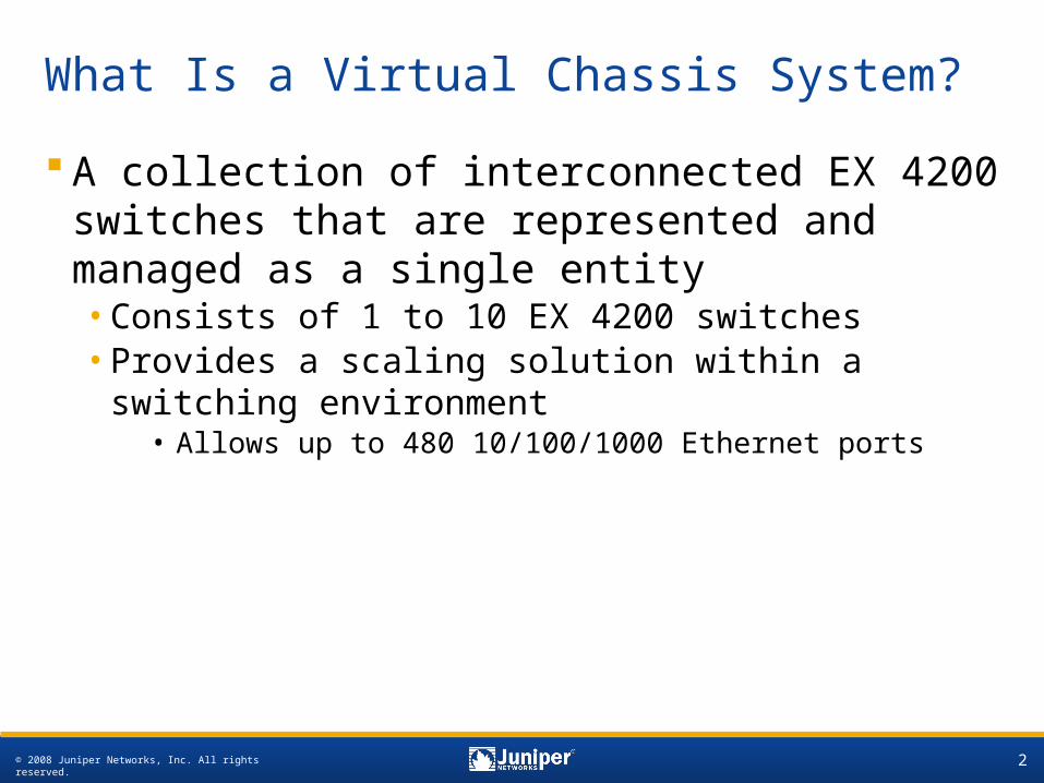
What Is a Virtual Chassis System?
A collection of interconnected EX 4200 switches that are represented and managed as a single entity•Consists of 1 to 10 EX 4200 switches•Provides a scaling solution within a switching
environment• Allows up to 480 10/100/1000 Ethernet ports
© 2008 Juniper Networks, Inc. All rights reserved. 3
Benefits of a Virtual Chassis System
Managed as a single switch•Simplifies management tasks such as software
upgrades•Spanning Tree Protocol is not required within Virtual
Chassis systems Provides control plane redundancy
•Facilitates master and backup Routing Engine election and management
Allows growth and expansion based on needs•Start with a single EX 4200 switch and grow as
needed (up to a maximum of 10 EX 4200 switches)

© 2008 Juniper Networks, Inc. All rights reserved. 4
Virtual Chassis Components (1 of 2)
EX 4200 platform switches•1 to 10 EX 4200 switches can be interconnected•Varying EX 4200 platforms supported in Virtual
Chassis systems PFE
•Each EX 4200 switch has 2 or 3 PFEs• 24-port platforms have 2 PFEs• 48-port platforms have 3 PFEs
•The PFEs interconnect to form the backplane
© 2008 Juniper Networks, Inc. All rights reserved. 5
Virtual Chassis Components (2 of 2)
VCPs:•Use proprietary VCB cables •VCPs are located on the rear of EX 4200 switches•Each EX 4200 switch comes with a .5 meter VCB
cable• Longer VCB cables are available
•No configuration required• Ports can be enabled or disabled
VCEPs:•Use fiber optics to connect remote member
switches•Require 2x10 Gigabit Ethernet uplink module•Must be enabled

© 2008 Juniper Networks, Inc. All rights reserved. 6
Deployment Options
Some common deployment options include:•Single-rack application
• Generally spans less than 5 meters•Top-of-rack application
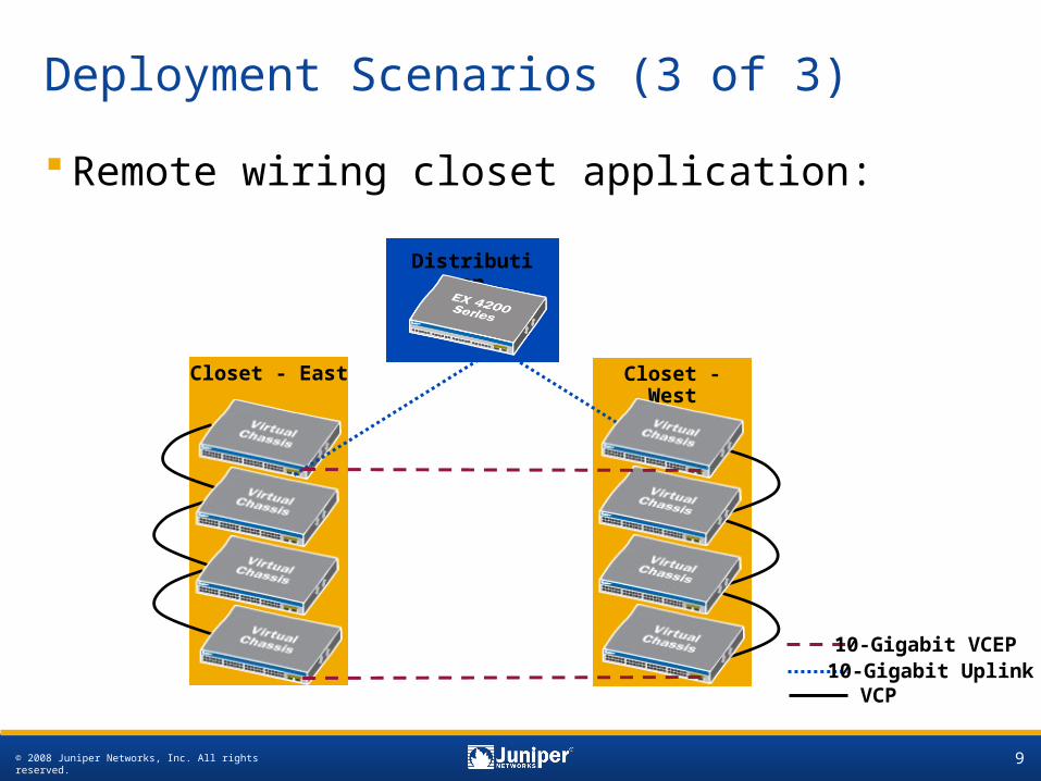
• Can span up to 15 meters•Remote wiring closet application
• Uses VCEPs to interconnect switches in remote wiring closets; can span more than 500 meters
© 2008 Juniper Networks, Inc. All rights reserved. 7
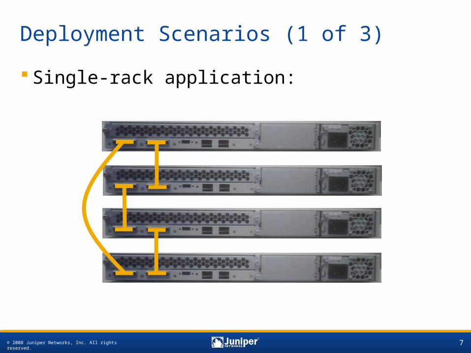
Deployment Scenarios (1 of 3)
Single-rack application:
© 2008 Juniper Networks, Inc. All rights reserved. 8
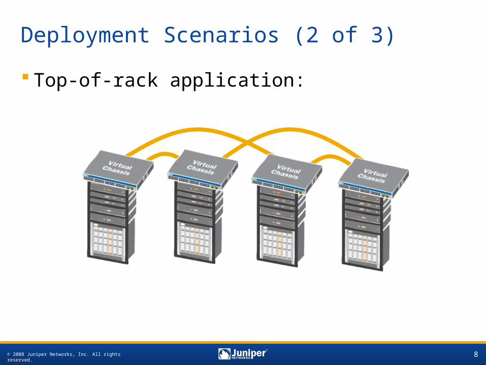
Deployment Scenarios (2 of 3)
Top-of-rack application:
© 2008 Juniper Networks, Inc. All rights reserved. 9
Deployment Scenarios (3 of 3)
Remote wiring closet application:
Distribution
Closet - East Closet - West
10-Gigabit VCEP10-Gigabit Uplink
VCP

© 2008 Juniper Networks, Inc. All rights reserved. 10
Installing a Virtual Chassis System (1 of 2)
Recommended process:1. Install desired master switch
• Power up desired master switch— switch becomes master and obtains member-id 0
• Assign mastership priority (255)
2. Add desired backup switch • Connect to master using VCB
cable• Power up desired backup switch—
switch is elected as backup and assigned member-id 1
• Assign mastership priority (254)
0
1
2
3
4
Linecard
Backup (Backup RE)
Master (Active RE)
Linecard
Linecard
ON
ON
© 2008 Juniper Networks, Inc. All rights reserved. 11
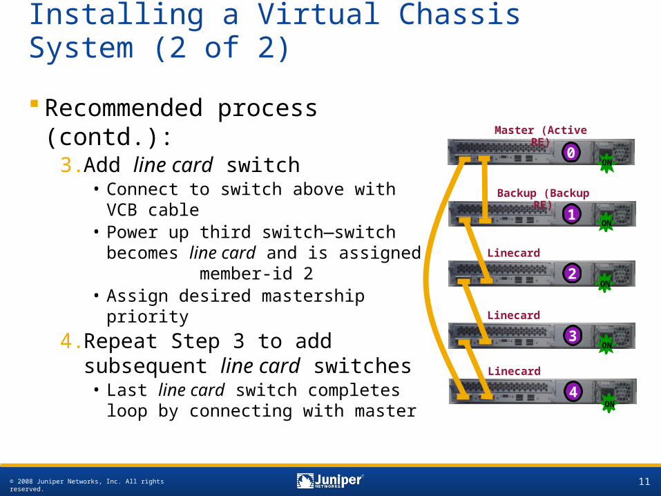
Installing a Virtual Chassis System (2 of 2)
Recommended process (contd.):
3. Add line card switch• Connect to switch above with
VCB cable• Power up third switch—switch
becomes line card and is assigned member-id 2
• Assign desired mastership priority
4. Repeat Step 3 to add subsequent line card switches• Last line card switch completes
loop by connecting with master
0
1
2
3
4
Linecard
Backup (Backup RE)
Master (Active RE)
Linecard
Linecard
ON
ON
ON
ON
ON
© 2008 Juniper Networks, Inc. All rights reserved. 12
Connectivity
Single management interface• Individual management Ethernet ports on member
switches are tied to a special management VLAN associated with a Layer 3 virtual management interface (vme)
Single management IP address•The Virtual Chassis system is managed as a single
network element; therefore, it has only one management IP address
Single virtual console•Connection to a console on any member switch in a
Virtual Chassis system is redirected to the VC master by virtual console software running on all member switches
© 2008 Juniper Networks, Inc. All rights reserved. 13
Software
Software upgrades need be performed only on the master switch
Software image compatibility check:•Member switches must be running the same software
version as the master to be part of a Virtual Chassis system
• If a version mismatch exists, a syslog message is generated•The master switch performs software compatibility
checks on the JUNOS software version on each member switch
• Switches with different hardware versions or model numbers can be members of the same Virtual Chassis system
•A CLI command is available to upgrade incompatible switches by downloading the correct image from the master over the Virtual Chassis cable
© 2008 Juniper Networks, Inc. All rights reserved. 14
Roles and Responsibilities
Master switch:•Manages all switches participating in the Virtual Chassis
system•Runs JUNOS software in a master role•Runs chassis management processes and control protocols
Backup switch:•Maintains a state of readiness should the master fail•Receives synchronized protocol state and forwarding table
information from master switch•Runs JUNOS software in a backup role
Line card:•The remaining member switches in the Virtual Chassis
system are candidate switches operating as if they are line cards
© 2008 Juniper Networks, Inc. All rights reserved. 15
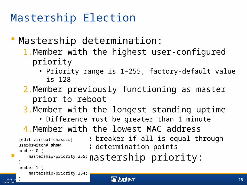
Mastership Election
Mastership determination:1. Member with the highest user-configured priority
• Priority range is 1–255, factory-default value is 128
2. Member previously functioning as master prior to reboot
3. Member with the longest standing uptime• Difference must be greater than 1 minute
4. Member with the lowest MAC address• Used as tie breaker if all is equal through the first 3
determination points
Configuring mastership priority:[edit virtual-chassis]user@switch# show member 0 { mastership-priority 255;}member 1 { mastership-priority 254;}
© 2008 Juniper Networks, Inc. All rights reserved. 16
Mastership Election Considerations
Once the master is elected:•The member that is second in the master election
process becomes the backup switch•If a master or backup fails, one of the line card
switches is elected as the new backup switch•Preemption occurs when a switch with a higher
mastership priority joins the Virtual Chassis system
© 2008 Juniper Networks, Inc. All rights reserved. 17
Member ID Assignment
Member ID assignment and considerations:•Master switch typically assumes member ID 0•Master switch assigns unique member IDs (1–9) to
each member switch •Member IDs are assigned in ascending order
based on the sequence in which member switches were added to the Virtual Chassis system
•Member ID is preserved across reboot within a Virtual Chassis system
•Member ID serves as slot number for interface naming
•Member ID can be manually configured through the CLI
© 2008 Juniper Networks, Inc. All rights reserved. 18
Topology Discovery (1 of 3)
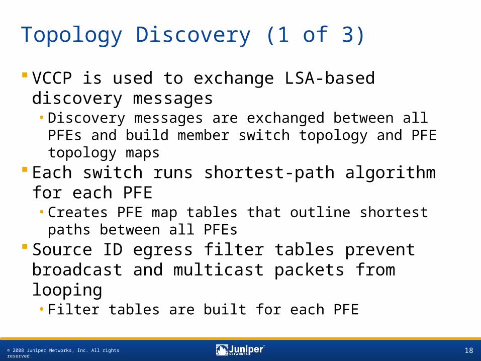
VCCP is used to exchange LSA-based discovery messages•Discovery messages are exchanged between all
PFEs and build member switch topology and PFE topology maps
Each switch runs shortest-path algorithm for each PFE•Creates PFE map tables that outline shortest paths
between all PFEs Source ID egress filter tables prevent
broadcast and multicast packets from looping•Filter tables are built for each PFE
© 2008 Juniper Networks, Inc. All rights reserved. 19
Topology Discovery (2 of 3)
b ca e fd h ig
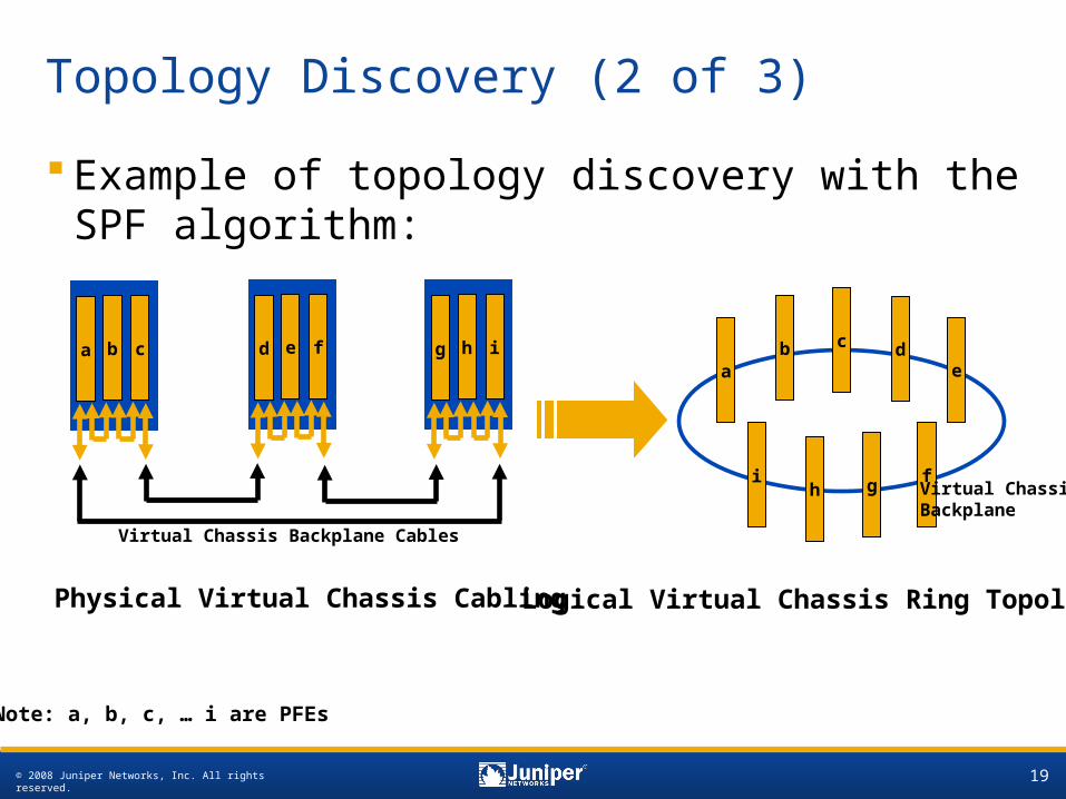
Physical Virtual Chassis Cabling
Virtual Chassis Backplane Cables
a
i
b
h
d
f
e
c
g
Logical Virtual Chassis Ring Topology
Virtual Chassis Backplane
Note: a, b, c, … i are PFEs
Example of topology discovery with the SPF algorithm:
© 2008 Juniper Networks, Inc. All rights reserved. 20
Topology Discovery (3 of 3)
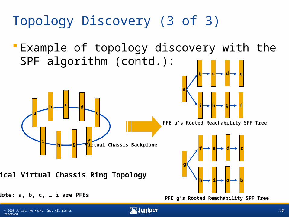
Example of topology discovery with the SPF algorithm (contd.):
a
i
b
h
d
f
e
c
g
Logical Virtual Chassis Ring Topology
Virtual Chassis Backplane
Note: a, b, c, … i are PFEs
a
b
i
c
h
d
g
e
f
PFE a’s Rooted Reachability SPF Tree
g
f
h
e
i
d
a
c
b
PFE g’s Rooted Reachability SPF Tree
© 2008 Juniper Networks, Inc. All rights reserved. 21
0
1
2
3
4
ge-0/0/10
ge-3/0/14
ge-0/0/28
ge-2/0/47
Packet Flow Overview (Interchassis)
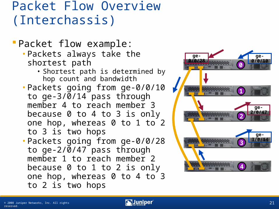
Packet flow example:•Packets always take the shortest
path• Shortest path is determined by
hop count and bandwidth•Packets going from ge-0/0/10 to
ge-3/0/14 pass through member 4 to reach member 3 because 0 to 4 to 3 is only one hop, whereas 0 to 1 to 2 to 3 is two hops
•Packets going from ge-0/0/28 to ge-2/0/47 pass through member 1 to reach member 2 because 0 to 1 to 2 is only one hop, whereas 0 to 4 to 3 to 2 is two hops
© 2008 Juniper Networks, Inc. All rights reserved. 22
Operational Monitoring
Key operational commands:•Use show chassis hardware to view installed
hardware and inventory details for Virtual Chassis system
•Use show virtual-chassis status to verify status and role of individual members within the Virtual Chassis system
•Use show virtual-chassis active-topology to view active topology details within Virtual Chassis system
•Use show virtual-chassis vc-port to view VCP status and associated details
•Use show virtual-chassis member-config to view Virtual Chassis configuration for individual members
•Use show virtual-chassis protocol commands to view interchassis communication details and status