Embed Size (px)
Citation preview

Section 3 Transportation
3 TRANSPORTATION
CONTENTS
3 TRANSPORTATION ......................................................................................................................... I
3.1 Introduction ............................................................................................................................... 3-4
3.1.1 Scope ............................................................................................................................. 3-4
3.1.2 Reference Documents ................................................................................................... 3-4
3.1.3 Objective ....................................................................................................................... 3-7
3.1.4 Guidelines...................................................................................................................... 3-7
3.1.5 Functions of a Transportation Corridor ........................................................................ 3-8
3.1.6 Road Safety Audit .......................................................................................................... 3-9
3.1.7 Design and Access Statements ...................................................................................... 3-9
3.2 Engineering Design................................................................................................................... 3-10
3.2.1 General ........................................................................................................................ 3-10
3.2.2 Corridor Alignment, Width and Cross Section components ....................................... 3-10
3.2.3 Formation Width ......................................................................................................... 3-12
3.2.4 Structures .................................................................................................................... 3-13
3.2.5 Visibility ....................................................................................................................... 3-13
3.2.6 Berms .......................................................................................................................... 3-13
3.2.7 Survey Marks ............................................................................................................... 3-14
3.2.8 Cut / Fill Batters ........................................................................................................... 3-14
3.2.9 Intersections ................................................................................................................ 3-14
3.2.10 Roundabouts ............................................................................................................... 3-16
3.2.11 No-exit roads, Cul-de-sac, Lanes and Private ways ..................................................... 3-17
3.2.12 Road Pavement ........................................................................................................... 3-19
3.2.13 Road Surfacing ............................................................................................................ 3-20
3.2.14 Road Drainage ............................................................................................................. 3-21
3.2.15 Parking ......................................................................................................................... 3-24
3.2.16 Footpaths, Pedestrian Accessways and Walkways ..................................................... 3-25
3.2.17 Facilities for Vision Impaired Pedestrians ................................................................... 3-26
3.2.18 Cycle Facilities ............................................................................................................. 3-27
3.2.19 Vehicle Crossings/Entrances ....................................................................................... 3-27
3.2.20 Road Lighting Design ................................................................................................... 3-30
3.2.21 Special Vehicle lanes ................................................................................................... 3-36
3.2.22 Traffic Control Devices – Line Marking and Signs ....................................................... 3-36
3.2.23 Feature Entrance Walls, Berm and Street Furniture ................................................... 3-36
3.2.24 Safety Barriers ............................................................................................................. 3-37
3.2.25 Fencing ........................................................................................................................ 3-37
3.2.26 Trees and Landscaping ................................................................................................ 3-37
3.2.27 Structures and Underpasses ....................................................................................... 3-38
3.2.28 Traffic Signals .............................................................................................................. 3-39
3.2.29 Traffic Calming Devices ............................................................................................... 3-39
3.2.30 Over-Dimensional Vehicle Routes ............................................................................... 3-39
3.3 Construction ............................................................................................................................. 3-39

Section 3 Transportation
3.3.1 Pavement Materials .................................................................................................... 3-39
3.3.2 New Pavement Construction ...................................................................................... 3-42
3.3.3 Ripping and Cement Stabilisation ............................................................................... 3-44
3.3.4 Testing ......................................................................................................................... 3-44
3.3.5 Concrete Works ........................................................................................................... 3-44
3.3.6 Road Stormwater Drainage (Kerb, Channel and catchpits) Construction .................. 3-47
3.3.7 Road Surfacing Construction ....................................................................................... 3-49
3.3.8 Berms .......................................................................................................................... 3-51
3.3.9 Footpaths, Cycle Paths and Vehicle Crossings ............................................................ 3-52
3.3.10 Privateways ................................................................................................................. 3-54
3.3.11 Road Signs and Street Furniture ................................................................................. 3-55
3.3.12 Attachment of Signs to Poles ...................................................................................... 3-61
3.3.13 Pedestrian Barrier Rails and Handrails ........................................................................ 3-62
3.3.14 Walkway Barriers and Cycle Racks .............................................................................. 3-62
3.4 Line Marking............................................................................................................................. 3-63
3.4.1 Setting Out and Timing ............................................................................................... 3-63
3.4.2 Paint Types .................................................................................................................. 3-64
3.4.3 Equipment Certificates and Staff Competence ........................................................... 3-65
3.4.4 Raised Pavement Markers (RPM) ............................................................................... 3-65
3.4.5 Removal of Line marking ............................................................................................. 3-65
3.4.6 High Friction or Coloured Aggregate Surfacing ........................................................... 3-66
3.4.7 Coloured Markings ...................................................................................................... 3-68
3.4.8 Temporary Markings ................................................................................................... 3-68
3.4.9 Non Standard Markings .............................................................................................. 3-69
3.5 Street Lighting Construction .................................................................................................... 3-69
3.5.1 Installation................................................................................................................... 3-69
3.5.2 Connection to network ............................................................................................... 3-69
3.5.3 Installation................................................................................................................... 3-70
3.5.4 Cables .......................................................................................................................... 3-70
3.5.5 Trenching..................................................................................................................... 3-71
3.5.6 Lighting Upgrades ....................................................................................................... 3-71
3.5.7 Existing Luminaires, Columns and Control Gear Made Redundant ............................ 3-71
3.5.8 Inspections and Testing ............................................................................................... 3-71
3.6 Traffic Signals ........................................................................................................................... 3-71
3.6.1 Scope ........................................................................................................................... 3-71
3.6.2 Specifications .............................................................................................................. 3-72
3.6.3 Traffic Signal Equipment ............................................................................................. 3-72
3.6.4 Communications ......................................................................................................... 3-73
3.6.5 Provision of Cameras .................................................................................................. 3-73
3.6.6 Warrantees, Guarantees and Maintenance ................................................................ 3-74
3.6.7 Design Requirements .................................................................................................. 3-75
3.6.8 Traffic Signal Procedure .............................................................................................. 3-76
3.7 Quality Systems ........................................................................................................................ 3-80
3.7.1 Inspections and Acceptance........................................................................................ 3-80
3.7.2 Testing Guidelines ....................................................................................................... 3-81
3.7.3 Testing Methods ......................................................................................................... 3-82
3.7.4 As-built Data Provision ................................................................................................ 3-87
Section 3 Transportation
LIST OF APPENDICES Appendix A Transportation Corridor Heirarchy Tables ............................................................................ 3-88
Appendix B Drawings ................................................................................................................................ 3-89
Appendix C Hamilton City Special Character Areas .................................................................................. 3-92
1. City Heart Paving & Kerb Upgrade Drawings ........................................................................... 3-92
Appendix D South Waikato Special Character Areas .............................................................................. 3-100
1. Litter Bins ............................................................................................................................... 3-100
LIST OF FIGURES
Figure 3-1: Traffic Signal Box Sign ................................................................................................................. 3-72
LIST OF TABLES
Table 3-1: List of Referenced Documents ...................................................................................................... 3-4
Table 3-2: Maximum Walking Distances from a Lot to a Collector or Arterial Road ..................................... 3-9
Table 3-3 Design Vehicle for Curve Widening .............................................................................................. 3-11
Table 3-4: Minimum Intersection Spacing.................................................................................................... 3-16
Table 3-5: Minimum Roundabout Design Criteria ........................................................................................ 3-16
Table 3-6: Pavement Layer Thickness for Local Residential Roads .............................................................. 3-20
Table 3-7: Gap Aggregate Grading Limits ..................................................................................................... 3-40
Table 3-8: Gap Aggregate Grading Fraction Limits ....................................................................................... 3-41
Table 3-9: Signage Specifications Additional ................................................................................................ 3-56
Table 3-10: Procedures: Signal Plans, Software and Commissioning ........................................................... 3-76
Table 3-11: Test Spacing locations and frequency ....................................................................................... 3-81
Table 3-12: Procedures ................................................................................................................................. 3-82
Table 3-13: Quality Systems Testing – Clegg Hammer Compliance Values ................................................. 3-83
Table 3-14: Quality Systems Testing – Nuclear Densometer Compliance Values ........................................ 3-83
Table 3-15: Maximum Benkelman Beam Deflections .................................................................................. 3-85
Table 3-16: Shape and Relative Height Tolerances ...................................................................................... 3-85
Table 3-17: Drawing Register ....................................................................................................................... 3-89
Section 3 Transportation
Page 3-3-4 Last Updated : 18 July 2017
3.1 Introduction
A safe and efficient transportation network is an essential contributor to the social, economic,
cultural and environmental wellbeing of our community. This Section builds on the
transportation provisions of the District Plan and gives requirements and guidance for the
design, construction and maintenance of the network. Transportation corridors that
incorporate facilities for vehicles, pedestrians, cyclists, mobility impaired, public transport,
utilities, and landscaping are the preferred method of providing for the transport needs of our
community.
3.1.1 Scope
This Section sets out the requirements for the design and construction of transportation
corridors within the city/district that are, or will be, managed by or vested to Council. It is also
to be used for maintenance of existing infrastructure, including asset renewal, unless the
standards are not compatible with the existing assets.
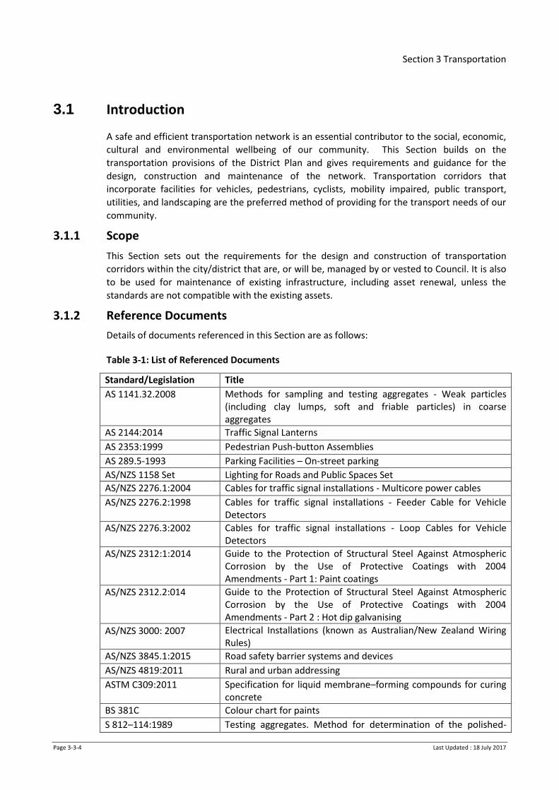
3.1.2 Reference Documents
Details of documents referenced in this Section are as follows:
Table 3-1: List of Referenced Documents
Standard/Legislation Title
AS 1141.32.2008 Methods for sampling and testing aggregates - Weak particles (including clay lumps, soft and friable particles) in coarse aggregates
AS 2144:2014 Traffic Signal Lanterns
AS 2353:1999 Pedestrian Push-button Assemblies
AS 289.5-1993 Parking Facilities – On-street parking
AS/NZS 1158 Set Lighting for Roads and Public Spaces Set
AS/NZS 2276.1:2004 Cables for traffic signal installations - Multicore power cables
AS/NZS 2276.2:1998 Cables for traffic signal installations - Feeder Cable for Vehicle Detectors
AS/NZS 2276.3:2002 Cables for traffic signal installations - Loop Cables for Vehicle Detectors
AS/NZS 2312:1:2014 Guide to the Protection of Structural Steel Against Atmospheric Corrosion by the Use of Protective Coatings with 2004 Amendments - Part 1: Paint coatings
AS/NZS 2312.2:014 Guide to the Protection of Structural Steel Against Atmospheric Corrosion by the Use of Protective Coatings with 2004 Amendments - Part 2 : Hot dip galvanising
AS/NZS 3000: 2007 Electrical Installations (known as Australian/New Zealand Wiring Rules)
AS/NZS 3845.1:2015 Road safety barrier systems and devices
AS/NZS 4819:2011 Rural and urban addressing
ASTM C309:2011 Specification for liquid membrane–forming compounds for curing concrete
BS 381C Colour chart for paints
S 812–114:1989 Testing aggregates. Method for determination of the polished-

Section 3 Transportation
Page 3-3-5 Last Updated : 18 July 2017
stone value
NZS 3104 : 2003 Specification for Concrete Production
NZS 3109 : 1997 Concrete construction
NZS 3116:2002 Concrete segmental and flagstone paving
NZS 3910:2013 Conditions of Contract for Building and Civil Engineering Construction
NZS 4121: 2001 Design for Access and Mobility – Buildings and Associated Facilities
NZS 4402.4.1.1:1986 Test 4.1.1 NZ Standard Compaction Test
NZS 4402.4.1.3:1986 Test 4.1.3 NZ Vibrating Hammer Compaction Test
NZS 4404:2010 Land development and subdivision infrastructure
NZS 4407:2015 Methods of sampling and testing road aggregates
NZS/AS 1657: 1992 Fixed platforms, walkways, stairways and ladders - design, construction and installation
NZ Transport Agency (NZTA) Standards, Specifications and Guidelines
Land Transport Rule Traffic Control Devices 2004 (with amendments)
NZTA Code of Practice for Temporary Traffic Management
NZTA Bridge Manual SP/M/022 (2013)
NZTA Manual of Traffic Signs and Markings (MOTSAM) – Part 1 : Traffic Signs
NZTA Road Safety Audit Procedures for Projects (Transfund 2004); interim update 2013
NZTA Supplement to 2004 Austroads Pavement Design Guide (2007)
NZTA Traffic Control Devices Manuals
Guides
NZTA Pedestrian Planning and Design Guide (2009)
NZTA Cycling Network Guidance – planning and design
NZTA Traffic Notes
NZTA Traffic Note 48 Light Vehicle Sizes and Dimensions : street survey results and parking space requirements
Manuals
NZTA RTS 4 Guidelines for Flush Medians (1991)
NZTA RTS 11 Urban Roadside Barriers and Alternative Treatments (1995)
NZTA RTS 14 Guidelines for Facilities for Blind and Vision Impaired pedestrians (2015)
NZTA RTS 18 NZ On Road Tracking Curves for Heavy Vehicles (2007)
Specifications
NZTA B/2 Construction of Unbound Granular Pavement Layers
NZTA B/5 In-Situ Stabilisation of Modified Pavement Layers
NZTA C/20 Erection and Maintenance of Traffic Signs Chevrons Markers and Sight Rails
NZTA F/1 Earthworks Construction
NZTA F/2 Pipe Subsoil Drain Construction
NZTA F/5 Corrugated Plastic Pipe Subsoil Drain Construction
NZTA M/1 Roading Bitumens

Section 3 Transportation
Page 3-3-6 Last Updated : 18 July 2017
NZTA M/4 Basecourse Aggregate
NZTA M/6 Sealing Chip
NZTA M/7 Line Marking Paint
MZTA M/7 Notes to Line marking Paint Specification (M/7)
NZTA M/10 Asphaltic Concrete
NZTA M/12 Raised Pavement Markers specification
NZTA M/14 Edge Marker Posts
NZTA M/17 W-Section Bridge Guardrail Specification
NZTA M/20 Long Life Line Marking Materials Specification
NZTA M/20 Notes to Long Life Line Marking Materials Specification (M/20)
NZTA M/23 Bridge Approaches and Specification for Road Safety Barrier Systems
Appendix A - List of Compliant Road Safety Hardware for Accepted Products (with interim acceptances)
NZTA M/24 Audio Tactile Profiled Road Markings Specification
NZTA M/26
Specification for Lighting Columns
Appendix A – Type Approved Passively Safe Lighting Columns
NZTA M30 Specification and guidelines for Road Lighting design
NZTA P/3 First Coat Sealing
NZTA P/4 Resealing
NZTA P/9 Asphaltic Concrete Paving Construction
NZTA P/11 Open Grade Porous Asphalt
NZTA P/12 Pavement Marking Specification
NZTA P/12 Notes Notes to Pavement Marking Specification (P/12)
NZTA P/14 Specification for Installation of Raised Pavement Markers
NZTA P/15P Fabrication and Assembly of Standard Guardrails and Handrails for Highway Bridges
NZTA P/22 Reflectorised Pavement Marking Specification
NZTA P/43 Specification for Traffic Signals
NZTA T/1 Benkelman Beam Deflection Measurements
NZTA T/8 Road marking Applicator Testing Specification
NZTA T/12 Long-Life Pavement Marking Material Applicator Testing
Austroads Guides
Austroads Guide to Road Design Part 3: Geometric Design
Austroads Guides to Road Design Part 4: Intersections and Crossings
Austroads Guides to Road Design Part 4A: Unsignalised and Signalised Intersections
Austroads Guide to Road Design Part 4B : Roundabouts
Austroads Guides to Road Design Part 4C: Interchanges
Austroads Guide to Road Design Part 6A: Pedestrian and cyclist paths
Austroads Guide to Pavement Technology Part 2 : Pavement Structural Design
Austroads Guide to Traffic Management Part 10 : Traffic Control and Communication Devices
Austroads Pavement Design for Light Traffic

Section 3 Transportation
Page 3-3-7 Last Updated : 18 July 2017
Other Documents
Auckland Regional Transport Authority
(ARTA)
Bus Stop Infrastructure Design Guidelines, May
2009
Thick Brick Australia Clay Paving Design
Ministry for the Environment (MfE) Crime Prevention through Environmental
Design (CPTED)
Health and Safety at Work Act 2015
Manual for Streets (UK Dept for Transport)
2007
New Zealand Building Code
NZ Roadmarkers Federation (NZRF) Manuals Industry ‘Best Practice’
Road Safety Manufacturers
Association (RSMA)
Compliance Standard for Traffic Signs (2010)
Electricity Regulations 2010
Electricity (Safety) Regulations 2010
NZ Electrical Code of Practice for Electrical
Safe Distances (NZECP 34:2001)
The Electricity Act 1992
3.1.3 Objective
The objective is to provide a hierarchical network of transportation corridors that respond to
land use and land form, provide safe and convenient transport for all road user modes, provide
access to adjacent property, travel choices, are well connected, safe to use and provide
corridors for utility services. They must be consistent in their design standards to provide
uniform guidance to users and be designed and built to provide the least whole of life cost to
the community, consistent with the desired level of service.
3.1.4 Guidelines
In designing the layout of a Transportation Corridor the following issues must be considered:
a) Zoning and likely use of the adjacent land
b) Land form and geological and cultural features
c) Connections to existing transport corridors
d) Linkages to other developments and amenities
e) Relationship to the concept for the total area
f) Recognition of the One Network Road Classification hierarchy
g) The relevant Council’s District Plan
h) Public transport requirements
i) Service/utility corridors and the impact the development will have on the capacity of the utilities in the adjacent areas
j) Protection of unique features
k) Pedestrian needs
l) Cyclist needs
m) Needs of mobility or visually impaired persons
n) Stormwater collection, treatment and disposal

Section 3 Transportation
Page 3-3-8 Last Updated : 18 July 2017
o) Access by vehicles needing to service the area e.g. refuse collection, street cleaning
p) Risk, reliability and redundancy
q) Green space and vegetation
r) Whole of life costs for the operation and maintenance of the asset including ease of cleaning, procurement and replacement of infrastructure when vandalised, damaged or at the end of its design life.
s) Mitigation of adverse effects of traffic:
i. Volume
ii. Speed
iii. Manoeuvrability
iv. Function
v. Parking
vi. Safety
vii. Noise, air and water pollution
3.1.5 Functions of a Transportation Corridor
A Transportation Corridor provides a space for interaction between people for a range of
purposes and access to land uses so that movement between places can occur.
Refer to the relevant District Plan for the transportation functional classification.
The three key functions of a Transportation Corridor are movement, place context and utility
corridor.
3.1.5.1 Movement
Linking places with transportation infrastructure that provides for a range of transport modes
to move people and goods efficiently.
3.1.5.2 Place Context
Creating public spaces for people to interact, exercise and enjoy where appropriate. There are
some transportation corridors where such activities would create health and safety issues. The
place function would be limited in such situations e.g. arterials and expressways - refer to the
relevant District Plan for the transportation hierarchy.
3.1.5.3 Utility Corridor
Providing corridors that network utility operators can use to service the city (e.g.
telecommunication, fibre, electricity, three waters, and gas networks).
3.1.5.4 Transportation Corridor Hierarchy
Each Council currently has their own transportation corridor hierarchy. These can be found in
the relevant District Plan. Quick links to these tables can be found in Appendix A.
3.1.5.5 Network Connectivity
Well-connected networks (roads and other links) are achieved with smaller block sizes and
regular connections. Network connectivity shall be designed to achieve:
a) Shorter travel distances
b) An increased number of alternative routes for all types of users (noting that this is not
the case with arterials and expressways).
Section 3 Transportation
Page 3-3-9 Last Updated : 18 July 2017
c) Increased opportunity for communities to interact
d) Improved access to; public transport, cycling and walking networks, access to
destinations such as schools, amenities and employment
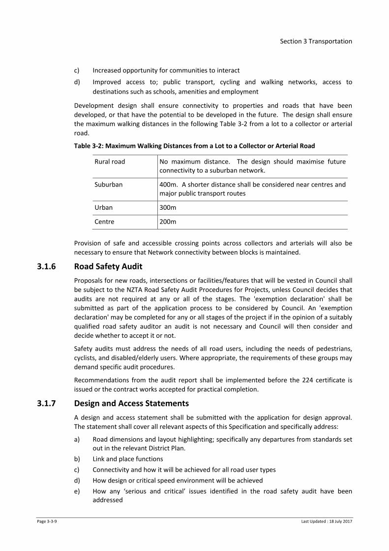
Development design shall ensure connectivity to properties and roads that have been
developed, or that have the potential to be developed in the future. The design shall ensure
the maximum walking distances in the following Table 3-2 from a lot to a collector or arterial
road.
Table 3-2: Maximum Walking Distances from a Lot to a Collector or Arterial Road
Rural road No maximum distance. The design should maximise future connectivity to a suburban network.
Suburban 400m. A shorter distance shall be considered near centres and major public transport routes
Urban 300m
Centre 200m
Provision of safe and accessible crossing points across collectors and arterials will also be
necessary to ensure that Network connectivity between blocks is maintained.
3.1.6 Road Safety Audit
Proposals for new roads, intersections or facilities/features that will be vested in Council shall
be subject to the NZTA Road Safety Audit Procedures for Projects, unless Council decides that
audits are not required at any or all of the stages. The 'exemption declaration' shall be
submitted as part of the application process to be considered by Council. An 'exemption
declaration' may be completed for any or all stages of the project if in the opinion of a suitably
qualified road safety auditor an audit is not necessary and Council will then consider and
decide whether to accept it or not.
Safety audits must address the needs of all road users, including the needs of pedestrians,
cyclists, and disabled/elderly users. Where appropriate, the requirements of these groups may
demand specific audit procedures.
Recommendations from the audit report shall be implemented before the 224 certificate is
issued or the contract works accepted for practical completion.
3.1.7 Design and Access Statements
A design and access statement shall be submitted with the application for design approval.
The statement shall cover all relevant aspects of this Specification and specifically address:
a) Road dimensions and layout highlighting; specifically any departures from standards set out in the relevant District Plan.
b) Link and place functions
c) Connectivity and how it will be achieved for all road user types
d) How design or critical speed environment will be achieved
e) How any ‘serious and critical’ issues identified in the road safety audit have been addressed
Section 3 Transportation
Page 3-3-10 Last Updated : 18 July 2017
f) Parking, passing and loading provisions
g) Criteria used in determining visibility distances and splays
h) Safety barrier requirements and considerations that have been made for alternative treatments
i) Impact on existing street features such as street furniture, pedestrian refuge facilities, bus stops & shelters, for visual consistency and also potential increase in usage.
3.2 Engineering Design
3.2.1 General
Roads shall be designed with reference to the transportation functional classification table contained in the relevant District Plan (see links in Appendix A) and NZS 4404 Section 3.3. However all references within Section 3.3 (NZS 4404) to Table 3.2 (NZS 4404), shall be taken instead to refer to the table in the relevant district plan.
3.2.1.1 Design Speed Environment
The relationship between carriageway width forward visibility and the design speed
environment for various road types is illustrated in the relevant transportation functional
classification table.
Traffic management facilities shall be included in the road design to ensure that the design
speed environment shown is achieved.
Design speed environments can be managed by physical and psychological devices such as
narrowed movement lanes, reduced forward visibility, parking, slow points, build outs,
chicanes, planting and landscaping, and street furniture and art works.
The Austroads Guide to Road Design - Part 3 : Geometric Design provides suitable guidance for
designing to a design speed. Reference can also be made to the Manual for Streets (UK
Department for Transport).
3.2.1.2 Special Character Zones
Where Special Character Zones (residential, heritage, natural, etc) are identified in the relevant
district plan, there may be associated local variations to the RITS. Refer to Appendix C and D.
3.2.2 Corridor Alignment, Width and Cross Section components
Horizontal alignment of transport corridors shall be based on terrain and the design speed
applicable to the road function. Vertical alignment of residential roads should ensure that
inclines can be negotiated during all weather conditions and sight distances are adequate for
safety. The gradient shall be considered as a planning factor when selecting locations for
shopping centres, service centres, or footpaths.
The minimum centreline radius for industrial roads, residential collector and sub-collector
roads is 80m. The minimum centreline radius for local residential roads is 15m. Reverse curves
are to be separated by an adequate length of straight in metres of 0.7 times the posted speed
limit.
Section 3 Transportation
Page 3-3-11 Last Updated : 18 July 2017
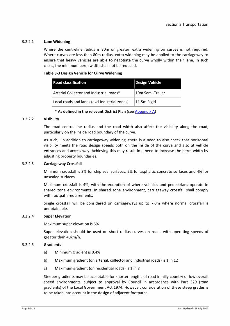
3.2.2.1 Lane Widening
Where the centreline radius is 80m or greater, extra widening on curves is not required.
Where curves are less than 80m radius, extra widening may be applied to the carriageway to
ensure that heavy vehicles are able to negotiate the curve wholly within their lane. In such
cases, the minimum berm width shall not be reduced.
Table 3-3 Design Vehicle for Curve Widening
Road classification Design Vehicle
Arterial Collector and Industrial roads* 19m Semi-Trailer
Local roads and lanes (excl industrial zones) 11.5m Rigid
* As defined in the relevant District Plan (see Appendix A)
3.2.2.2 Visibility
The road centre line radius and the road width also affect the visibility along the road,
particularly on the inside road boundary of the curve.
As such, in addition to carriageway widening, there is a need to also check that horizontal
visibility meets the road design speeds both on the inside of the curve and also at vehicle
entrances and access way. Achieving this may result in a need to increase the berm width by
adjusting property boundaries.
3.2.2.3 Carriageway Crossfall
Minimum crossfall is 3% for chip seal surfaces, 2% for asphaltic concrete surfaces and 4% for
unsealed surfaces.
Maximum crossfall is 4%, with the exception of where vehicles and pedestrians operate in
shared zone environments. In shared zone environment, carriageway crossfall shall comply
with footpath requirements.
Single crossfall will be considered on carriageways up to 7.0m where normal crossfall is
unobtainable.
3.2.2.4 Super Elevation
Maximum super elevation is 6%.
Super elevation should be used on short radius curves on roads with operating speeds of
greater than 40km/h.
3.2.2.5 Gradients
a) Minimum gradient is 0.4%
b) Maximum gradient (on arterial, collector and industrial roads) is 1 in 12
c) Maximum gradient (on residential roads) is 1 in 8
Steeper gradients may be acceptable for shorter lengths of road in hilly country or low overall
speed environments, subject to approval by Council in accordance with Part 329 (road
gradients) of the Local Government Act 1974. However, consideration of these steep grades is
to be taken into account in the design of adjacent footpaths.

Section 3 Transportation
Page 3-3-12 Last Updated : 18 July 2017
3.2.2.6 Vertical Curves
Vertical curves shall comply with the requirements of Austroads Guide to Road Design Part 3:
Geometric Design, section 8.6 Vertical Curves. For areas where the design speed is ≤ 50 km/h,
vertical curves shall have a minimum length of 20m, except where the grade change is ≤ 1%
where the minimum vertical curve length is 10m for centre lines. Kerb and channel grades
should not be flatter than 1 in 300 within the vertical curve.
3.2.2.7 Cross-section
Typical road widths are provided in the relevant district plan. Preservation or capitalisation of
some natural feature of a landscape or existing specimen tree(s) may dictate an irregular
shaped road width.
Certain carriageway and berm geometrics, utility services and stormwater swales, may require
that the road width be increased, but usually just locally.
3.2.2.8 Road Reserve
In some circumstances an increased overall road reserve may be necessary for utilities
provision or increased amenity, stormwater drainage, landscape or urban design element. In
other circumstances, reserve widths may be reduced if development is only on one side of the
road or the road is only one way.
All rural road reserve boundaries shall be fenced. Livestock fencing requirements are
contained in Section 7 - Clause 7.3.12.2.
3.2.2.9 Movement Lanes
One movement lane in each direction is typical but the requirements vary according to the
nature and function of the road. Refer to the relevant district plan.
3.2.2.10 Parking, Passing and Loading
Allowance for parking, passing and loading activities shall be provided in accordance with the
relevant district plan and section 3.3.6 of NZS 4404.
3.2.2.11 Cycle Facilities
Cycle facilities shall be provided in accordance with the requirements set out in the relevant
district plan and/or cycle/biking plan and shall be marked in accordance with the Traffic
Control Devices Manual and Drawings.
3.2.2.12 Shoulder Widths
Shoulder widths on rural roads need to be assessed for each project, based on the speed
environment of the area, terrain and activities. For high speed environments where high non-
motorised use is expected, shoulder widths may need to be increased to optimise overall road
safety. Refer to Table 3.2 NZS 4404.
3.2.3 Formation Width
Formation width shall be sufficient to contain the functions described in 3.2.2.8 above. Where
topography dictates, the formation width should extend beyond the carriageway edge by
500mm, with batters providing a smooth transition to the adjacent building lot grades.

Section 3 Transportation
Page 3-3-13 Last Updated : 18 July 2017
3.2.4 Structures
Where structures retaining private lots are required, these shall be fully located on the lot, not
within the road reserve.
3.2.5 Visibility
The driver sight distance requirements relate to the road classification function and vehicle
speeds.
Visibility splays and envelopes may require the road boundary to be set back (refer to Drawing
D3.1.5). Trees shall not be planted in the visibility splay; only road lighting columns and road
signs shall be considered. More detail on requirements for planting within visibility splays is
given in the landscape section.
Horizontal and vertical sight distances along a road shall be designed in accordance with
Austroads Guide to Road Design Part 3: Geometric Design, considering the wet surface
coefficient. The stopping sight distance measured round a curve shall be along a line 1.5m into
the lane width from the inside kerb.
The developer shall submit with the engineering plans the criteria used in determining the
visibility distances.
3.2.6 Berms
Berms shall be provided between the edge of the formed carriageway and the road legal
boundary to accommodate footpaths, road signs, road lighting, underground services,
landscaping, stormwater control and grass areas. (Refer Drawing D3.1.3)
Berms shall be of adequate width to:
a) Achieve safe clearances between the carriageway edge and any obstacle (minimum
600mm for urban and 1500mm for rural areas).
b) Allow running of utility services and placing of street lighting poles within the berm
c) Provide adequate space between the road reserve boundary and the carriageway edge
to enable residents to safely enter the road traffic
d) Allow room for efficient road edge and edge drain maintenance
e) Allow adequate space for the effective operation and maintenance of any form of
stormwater management device
f) Allow sufficient width to allow for adequate growth of the plants/ trees and ease of their
maintenance.
g) Allow for use of a lawnmower for general maintenance - narrow grass strips less than
650mm wide should be avoided
The minimum width of berm shall be in accordance with the relevant District Plan except for
private ways (Refer Drawing D3.1.6) and shared environments.
Berm crossfall shall typically be 4%, however localised grass berm cross falls may range
between 2% and 10% but must be able to be easily mown by the adjacent property owner.
Engineering drawings should identify any variances from the typical crossfalls. Berm crossfall

Section 3 Transportation
Page 3-3-14 Last Updated : 18 July 2017
shall be satisfactory to accommodate vehicle crossings with a maximum of 16% but can’t
negatively impact on the footpath. (Refer Drawing D3.1.4)
On rural roads berm crossfall to be a maximum of 25% starting at the edge of the carriageway
shoulder or surface water channel.
3.2.7 Survey Marks
Survey marks shall be installed in a separate, purpose built concrete slab, clear of vehicle and
pedestrian facilities. Survey marks are not to be installed on kerb lines.
3.2.8 Cut / Fill Batters
To be read in conjunction with Earthworks Section 2.
3.2.8.1 Urban Roads
Cut and fill batters for roads shall generally be constructed within the Transportation Corridor
(refer clause 3.2.6 for berms).
a) With a maximum grade of 20% (1:5) starting at the road boundary. Where
circumstances dictate a steeper grade is necessary, and it is longer than 10 metres, a
geotechnical assessment of the slope shall be provided together with specific access
design (Refer to Earthworks Section 2).
b) Any retaining wall designed to support the road or footpath shall be constructed within
the transportation corridor and will likely require a building consent
c) Where Council consider the stability of any planned embankment is in doubt, a stability
analysis of the slope under saturated conditions may be required
3.2.8.2 Rural Roads
a) Rural batters for cuttings and embankments shall usually be constructed inside the
Transportation Corridor
b) Batters less than 750mm high shall be cut at 1:4 and shall be topsoiled and grassed.
(Refer to Landscape Section, Clauses 7.3.4 and 7.3.6)
c) Batters 750mm high and above shall be cut at 1:2 and shall be protected from face
erosion by hydro-seeding or similar (refer to Landscape Section)
d) Batters 4.5m high and above shall be assessed by a Geotechnical Professional. In
undertaking this check and determining the appropriate erosion protection the
Geotechnical Professional shall take into account:
i. The type of soils present in the cutting
ii. The degree of possible erosion and its effect on long term stability, the safety of
road users, and adjacent property owners
3.2.9 Intersections
3.2.9.1 Intersection and Alignment Design
All intersections shall be designed in accordance with Austroads Guides to Road Design parts 4
and 4A.

Section 3 Transportation
Page 3-3-15 Last Updated : 18 July 2017
Generally, in urban areas, roads should intersect only with roads in the same class or those
immediately above or below in classification. T-junctions are preferred to cross intersections
particularly for local roads. The angle of intersection should be 90o, although a minimum angle
of 70o can be used when justified by other constraints. Multi-leg intersections may require
control by roundabouts. Intersections on curves, particularly on the inside of curves, other
than large radius curves, are to be avoided.
All road intersections in residential areas should have a kerb radius at intersections of 4m to
6m. An alternative and reduced kerb radius may be considered to enhance pedestrian facility
in low speed environments, and shall be subject to the approval of Council.
All intersections in industrial areas should have a minimum kerb radius of 13.5m with corner
splays of 6m, or subject to specific design.
Intersections in all other 50 km/h or lower speed environments shall have the lot corners
splayed by a minimum of 4m along both boundaries, although these may be dispensed with in
low design speed environments provided that there is adequate provision for pedestrians and
utility services.
Corner boundary splays shall be subject to specific design in higher speed environments, to
ensure safe visibility at intersections.
3.2.9.2 Arterial Road Intersections
For intersections with arterial roads, the engineering plans shall show the sight distance
provided at each intersection, plus the following information:
a) Design Speed
b) Design Vehicle
c) Distance from limit lines to viewpoint (LV)
d) Approach Sight Distance (ASD)
e) Safe Intersection Sight Distance (SISD)
f) All radii
The SISD shall be determined with an object of height 0.6m.
Reference can also be made to Austroads Guides to Road Design Parts 4, 4A and 4C.
3.2.9.3 Intersections with State Highways
In the case of roads intersecting or joining State Highways, consultation must be undertaken
with the NZTA with regard to appropriate standards prior to commencing design.
3.2.9.4 Grades at Intersections
Gradients within 30m of intersections shall be:
a) For Local Roads - less than 1 in 33 where practicable and not greater than 1 in 10
b) For Collector and Arterial Roads - less than 1 in 50
A plateau with minimum grades, of at least 10m is to be provided at any intersection where a
vehicle may be expected to stop and give way to other vehicles e.g. at a Give Way control.
Section 3 Transportation
Page 3-3-16 Last Updated : 18 July 2017
3.2.9.5 Channelisation at Intersections
All side roads that have direct access to a collector or arterial road (existing or proposed as
defined by the relevant District Plan and/or Structure Plan) shall be channelised using either
kerb extensions and / or a central throat island at the intersection with the collector or arterial
road. Such treatments are to be designed and constructed in accordance with this
specification. Side roads expected to carry less than 120 v.p.d (12 dwellings) and have a
carriageway width of 8m or less do not require channelisation.
3.2.9.6 Priority Controls
All priority intersections must fulfil the requirements of the Land Transport Rule: Traffic
Control Devices 2004, associated NZTA Traffic Control Devices Manuals, and the NZTA
Pedestrian Planning and Design Guide.
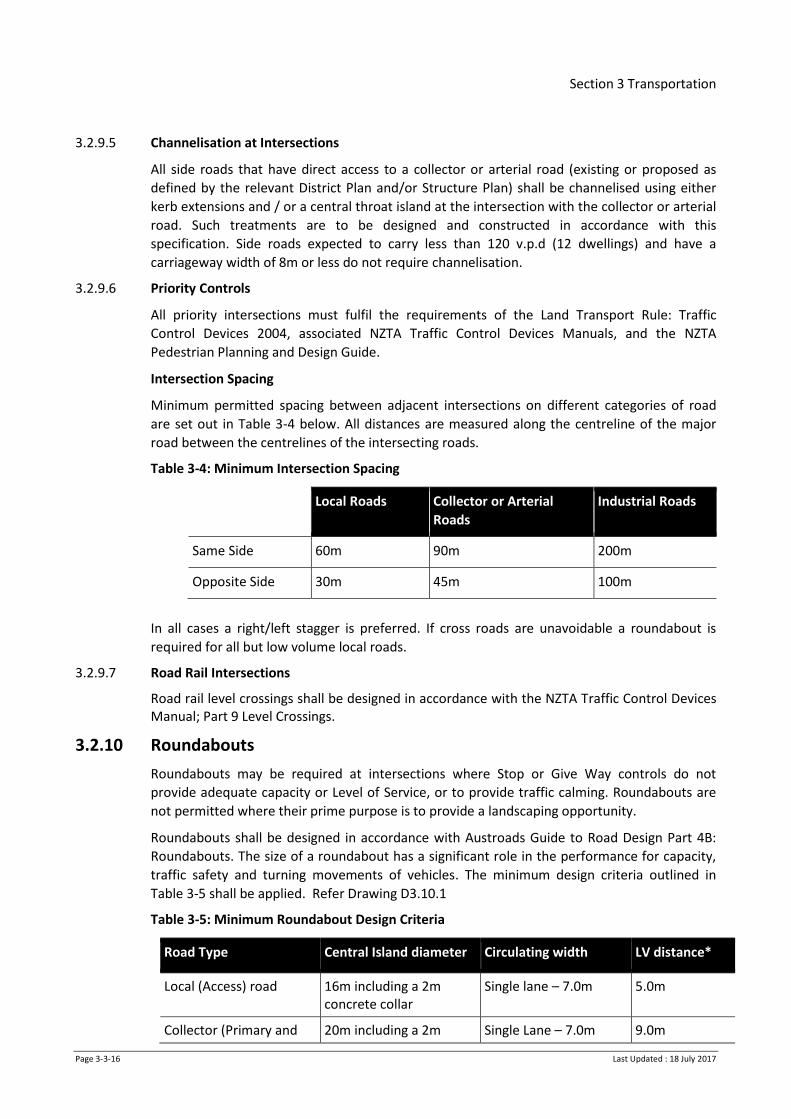
Intersection Spacing
Minimum permitted spacing between adjacent intersections on different categories of road
are set out in Table 3-4 below. All distances are measured along the centreline of the major
road between the centrelines of the intersecting roads.
Table 3-4: Minimum Intersection Spacing
Local Roads Collector or Arterial
Roads
Industrial Roads
Same Side 60m 90m 200m
Opposite Side 30m 45m 100m
In all cases a right/left stagger is preferred. If cross roads are unavoidable a roundabout is
required for all but low volume local roads.
3.2.9.7 Road Rail Intersections
Road rail level crossings shall be designed in accordance with the NZTA Traffic Control Devices Manual; Part 9 Level Crossings.
3.2.10 Roundabouts
Roundabouts may be required at intersections where Stop or Give Way controls do not
provide adequate capacity or Level of Service, or to provide traffic calming. Roundabouts are
not permitted where their prime purpose is to provide a landscaping opportunity.
Roundabouts shall be designed in accordance with Austroads Guide to Road Design Part 4B:
Roundabouts. The size of a roundabout has a significant role in the performance for capacity,
traffic safety and turning movements of vehicles. The minimum design criteria outlined in
Table 3-5 shall be applied. Refer Drawing D3.10.1
Table 3-5: Minimum Roundabout Design Criteria
Road Type Central Island diameter Circulating width LV distance*
Local (Access) road
16m including a 2m concrete collar
Single lane – 7.0m 5.0m
Collector (Primary and 20m including a 2m Single Lane – 7.0m 9.0m

Section 3 Transportation
Page 3-3-17 Last Updated : 18 July 2017
Road Type Central Island diameter Circulating width LV distance*
Secondary) road concrete collar Dual lane – 10.5m
Arterial (Primary and Secondary) or Industrial road
24m including a 2m concrete collar
Single Lane – 7.0m Dual lane – 10.5m
9.0m
(*LV distance is defined as the minimum distance from limit lines to point of view)
Visibility is an important factor to ensure safety standards are met, Austroads Guide to Road
Design Part 4B, Criteria 1 and 2 for sight distance are both mandatory requirements.
Achievement of Criterion 3 is desirable.
Minimum criterion may be reduced if:
a) Physical constraints such as a building/structure prevent practical implementation of
minimum design criterion
b) Roundabout can be shown to form a traffic control device as part of a Local Area Traffic
Management scheme
Any roundabout below the desirable design criteria requires approval by Council.
Supporting evidence to show that the design will meet capacity, safety and turning movements
of intended vehicles shall be supplied.
Traffic modelling shall be provided to show that the design can mitigate the effects of traffic
generation due to the development. Where applicable, consideration shall be given for future
network growth and development. This could include intersection modelling using software
such as SIDRA.
The engineering plans shall show, the visibility splays for each approach of each roundabout,
landscaping details, signage, road marking, and state the:
a) Design Speed – both approach and circulating
b) Design Vehicle and Turning Path
c) LV Distance
d) Central Island Diameter
e) Circulating Width
f) Level of Service
g) Provisions for pedestrians and cyclists to ensure their safety when negotiating the
roundabout
A copy of the Safety Audit and evidence of compliance with recommendations must be
included.
3.2.11 No-exit roads, Cul-de-sac, Lanes and Private ways
3.2.11.1 No Exit Roads
‘No-exit’ roads should not be provided where through roads and connected networks can be
designed. Where no-exit roads cannot be avoided, they should ensure connectivity for
pedestrians and cyclists and have no-exit signage.
Section 3 Transportation
Page 3-3-18 Last Updated : 18 July 2017
Public no-exit roads and lanes shall provide for road turning at the end of the road for an
appropriate vehicle as described in NZTA standard RTS 18. No Exit roads shorter than 60m may
provide reduced turning facilities but must cater for 11m rigid trucks (e.g. rubbish collection).
The design of turning facilities for light vehicles in urban areas shall be in accordance with AS
2890.5. See Figures 3.3 and 3.4 for acceptable solutions.
Turning heads will be required at the end of all rural no exit roads in accordance with
Austroads Rural Road Design.
An on-road turning area may provide for parking or landscaping/hard standing in the centre of
the turning area. The minimum kerb gradient around turning heads shall be 0.5%. Appropriate
drainage shall be provided.
3.2.11.2 Cul-de-sac Design
The design of cul-de-sac turning areas shall be in accordance with Drawing D3.1.7 or NZS4404
except in commercial and industrial areas where the minimum radius shall be 15m to
accommodate the turning movements of service vehicles.
The maximum long or cross section slope in turning heads is 6%, with the desirable matching
normal camber.
All urban roads shall have kerb and channel with associated stormwater collection and disposal
systems provided on all cul-de-sac heads to the tangent point.
Staged road construction will require temporary cul-de-sacs to be built.
For rural roads, Council may require kerb and channel with associated stormwater collection
and disposal systems to be provided on cul-de-sac heads where conventional shoulder/berm
surface runoff is unable to be achieved to Council’s satisfaction.
3.2.11.3 Lanes
The minimum carriageway width permitted is 3.5m. Service Lanes are to have concrete edging
both sides and stormwater is to be collected and disposed of. Specific geometric and
pavement design is required, as covered in clause 3.2.12. Carriageway surfacing is to be
asphalt conforming to the specifications in clauses 3.2.13.2 and 3.3.9.8.
3.2.11.4 Private ways
Urban Residential Privateways
Urban residential privateways are to be in accordance with the relevant District Plan. (Refer
also to Drawing D3.1.6)
The minimum permitted inside radius of curves shall be 9.0 m. The gradient shall not exceed
1:6. Where the gradient exceeds 1:6, any safety provisions required by Council shall be
provided. A passing bay shall be provided at every 75m of privateways.
Industrial Privateways
a) The minimum carriageway width for an industrial privateway serving a single lot is 4m.
For an industrial privateway serving two or more lots the minimum carriageway width is
6.4m. Berm widths each side are to be 1.8m minimum. The minimum permitted inside
radius of curves is 12m.
Kerb and channel is to be heavy duty in accordance with Drawing D3.3.3. Stormwater shall not
discharge across the vehicle crossing from the privateway to the road. Vehicle crossings to
Section 3 Transportation
Page 3-3-19 Last Updated : 18 July 2017
privateway shall be designed and constructed in accordance with clause 3.2.19 and Drawing
D3.1.6.
Rural Residential Privateways
a) For rural residential privateways serving ≤ 4 lots and ≤ 250m in length, the total
minimum permitted sealed carriageway width is 3.5m, with the total width of the
privateway a minimum of 7.0m.
b) For rural residential privateways serving ≥ 5 lots or ≥ 250m length, the total minimum
permitted sealed carriageway width is 4.0m, with the total width of the privateway a
minimum of 7.5m. The crossfall shall be 4%. A passing bay should be considered.
3.2.12 Road Pavement
Pavements shall be provided to all roads such that vehicle loads may be carried without
distress, in all weathers, for at least the design life with only normal routine maintenance and
periodic re-surfacing. Pavements shall generally be flexible granular pavements with thin
surfacing layers, however where this is not sufficient or a more innovative solution can be
implemented, it may be approved by Council.
Stabilisation additives are not permitted in new pavement construction, unless specifically
agreed to by Council.
3.2.12.1 Pavement Design
A pavement design may be carried out by one of the following methods:
i) Sealed Pavement - Specific Design
This method shall be used for all industrial and high volume (over 3000 vpd) residential roads.
It may be used for roads of lower classification.
Pavement design shall use the methodology of Austroads Guide to Pavement Technology, Part
2 and the NZ Supplement to the Austroads Pavement Design Guide.
Designs for local roads may also use Austroads Pavement Design for Light Traffic.
Use of alternative materials such as recycled aggregates or the treatment of lower grade
material is encouraged. The use of stabilisation agents may be considered by Council for
subgrade and sub-base improvement, but not basecourse stabilisation.
Factors to be included in the design are:
a) Design Period - 25 years
b) Trips generated per household per day - 10
c) Annual HCV growth factor - 3 % minimum unless otherwise outlined by Council
d) Load factor the Presumptive ESA/HCV of 1.44 shall be used for design purposes unless
otherwise outlined by Council.
e) % HCV 1.5% local residential road/3.5% collector and higher classification/10% industrial
and 9% rural roads
The design report shall provide the following information as a minimum.
Results of soils investigations
Section 3 Transportation
Page 3-3-20 Last Updated : 18 July 2017
Design assumptions and figures
Material specifications
Engineering Drawings
QA measures for construction
ii) Sealed Pavement - Default Design
This method may be used for local residential roads only. Using this design does not exempt
the construction from any tests nor compliance with any targets and does not provide any
guarantee that the resulting pavement will comply with all testing requirements. Pavements
shall comply with the depth and aggregate specified in the following table.
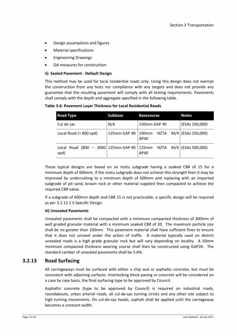
Table 3-6: Pavement Layer Thickness for Local Residential Roads
Road Type Subbase Basecourse Notes
Cul de sac N/A 150mm GAP 40 (ESAs 100,000)
Local Road (< 800 vpd) 125mm GAP 40 100mm NZTA M/4 AP40
(ESAs 250,000)
Local Road (800 – 3000 vpd)
125mm GAP 40 125mm NZTA M/4 AP40
(ESAs 500,000)
These typical designs are based on an insitu subgrade having a soaked CBR of 15 for a
minimum depth of 600mm. If the insitu subgrade does not achieve this strength then it may be
improved by undercutting to a minimum depth of 600mm and replacing with an imported
subgrade of pit sand, brown rock or other material supplied then compacted to achieve the
required CBR value.
If a subgrade of 600mm depth and CBR 15 is not practicable, a specific design will be required
as per 3.2.12.1 i) Specific Design.
iii) Unsealed Pavements
Unsealed pavements shall be compacted with a minimum compacted thickness of 300mm of
well graded granular material with a minimum soaked CBR of 20. The maximum particle size
shall be no greater than 100mm. This pavement material shall have sufficient fines to ensure
that it does not unravel under the action of traffic. A material typically used on district
unsealed roads is a high grade granular rock but will vary depending on locality. A 50mm
minimum compacted thickness wearing course shall then be constructed using GAP20. The
standard camber of unsealed pavements shall be 5-6%.
3.2.13 Road Surfacing
All carriageways must be surfaced with either a chip seal or asphaltic concrete, but must be
consistent with adjoining surfaces. Interlocking block paving or concrete will be considered on
a case by case basis, the final surfacing type to be approved by Council.
Asphaltic concrete (type to be approved by Council) is required on industrial roads,
roundabouts, urban arterial roads, all cul-de-sac turning circles and any other site subject to
high turning movements. On cul-de-sac heads, asphalt shall be applied until the carriageway
becomes a constant width.

Section 3 Transportation
Page 3-3-21 Last Updated : 18 July 2017
3.2.13.1 Chip Seal Surfacing
The first coat shall be a two coat 3/5 chip seal for most residential roads. A further coat of chip
seal must be applied between 3 and 18 months later as part of the project cost. If the second
coat seal is going to be applied more than 12 months later, the defects liability period will need
to be extended. Other chip seal designs may be considered and approved by Council.
3.2.13.2 Asphaltic Concrete Surfacing.
Asphaltic Concrete may be used as an alternative surfacing to Chip Seal. There are stricter
requirements for pavement stiffness if asphalt is to be used. Selection of an appropriate mix
for arterial and industrial sites is to be agreed with Council. For further details and
requirements see clause 3.3.7.3.
Alternative asphaltic concrete products, such as Stone Mastic Asphalt (SMA) or Open Graded
Porous Asphalt (OGPA), may be used with Council approval.
3.2.13.3 Concrete Block Paving
Concrete block pavers are to be used only following approval with Council. The concrete block
pavers shall comply, and laying shall be in accordance with, NZS 3116 ‘Concrete segmental and
flagstone paving’.
Pavements in NZS 3116 titled ‘Light vehicular’ are not acceptable for road surfacing.
3.2.14 Road Drainage
3.2.14.1 General
All roads shall be provided with facilities for the collection and disposal of both stormwater
and subsoil water suitable to cope with the stormwater level of service for the area. Refer
Stormwater Section Table 4.7. Designs shall consider the following factors:
a) Groundwater recharge through soakage systems
b) Quality of water discharged to receiving environments either directly or via connection
to an existing piped network
c) Requirements of the Waikato Regional Council
d) Overland flow paths. Generally urban and industrial roads should be lower than
adjoining land and rural roads higher than surrounding farmland.
e) Water discharged from adjoining land (including current and future land use)
f) Public safety
g) Minimising of future maintenance requirements
h) Capacity of any existing piped network
i) Cyclists
j) Reduction of peak discharge rate
k) The depth of water in secondary flow paths should not exceed the flotation depth of
vehicles of 150mm (see Section 3.2.14.8).
3.2.14.2 Kerb and Channel, Vertical Kerb and Island Kerb
All profiles are to be founded on the subgrade with a CBR of at least 15. Where pavement
depth is greater than 150mm, the profile shall be laid on a minimum of 75mm of compacted

Section 3 Transportation
Page 3-3-22 Last Updated : 18 July 2017
GAP40. For kerbs with tight radii (<5 metres), or carriageway narrower than standard, ‘Heavy
Duty Kerb and Channel’ shall be used. Refer to Drawing D3.3.3.
Urban Roads
a) Kerb and channel shall be provided on both sides of the carriageway in all urban areas
b) Mountable kerb and channel is not permitted in built up areas
c) Subsoil under-channel drains shall be provided along kerb lines including medians,
roundabouts and traffic control islands as shown on the Drawing D3.4.1 except where it
can demonstrated that they are not necessary (e.g. where the underlying soil has a high
porosity or at high points in the topography)
d) Additional subgrade drainage may be required
Industrial Roads
Any road, street or lane constructed within an industrial zone (as specified in the relevant District Plan) shall be designed to meet the geometric standards for arterial roads, and incorporate industrial kerb and channel in accordance with Drawing D3.3.3.
Rural Roads
a) Kerb and channel shall be required where necessary to control stormwater runoff.
Generally it may be considered for construction adjoining cut and fill batters to control
potential scouring of the water tables and embankments.
b) Subsoil drains shall be installed adjoining all cut batters.
Refer to Drawing D3.4.1.
Dish Channels and Depressed Kerb and Channel
Dish channels are not to be used in carriageways. Where drainage is required for bus or
parking bays a depressed kerb and channel should be used. The design profile should be the
same as Commercial Channel Crossings, shown on Drawing D3.3.2.
For dish channels within footpaths or accessways, these are to be founded on subgrade with a
CBR not less than 7. Refer to profiles in Drawing D3.3.3.
Slot Drains
Slot drains must be avoided at the design phase if at all possible. The use of surface channels
and catchpits is more desirable. Slot drains can be used to cater for vehicle break over angles.
Refer to Drawing D3.3.7.
3.2.14.3 Catchpits
Catchpit spacing and location shall be designed to the following criteria:
a) Catchpit spacing is to have a:
i. Maximum gross area drained (carriageway, berm and footpath) = 900m²
ii. Maximum area of carriageway drained = 450m²
iii. Maximum of = 90m
iv. Maximum where stormwater from private houses connect to kerb and channel =
60m
b) Preferred location of catchpits:

Section 3 Transportation
Page 3-3-23 Last Updated : 18 July 2017
i. At intersections, at the kerb line tangent point
ii. Upstream of pedestrian crossings
iii. At changes of gradient on steep roads
iv. Cul-de-sac heads
v. Mid lot, to avoid vehicle and pedestrian crossings.
c) A double catchpit is required:
i. At the lowest point in a sag vertical curve
ii. At the ends of a cul-de-sac where water falls to the end
iii. On all channels where the gradient is steeper than 5%
d) Catchpits in swales require a specific design
e) Catchpit grates will be cycle-friendly designs as per Drawing D4.8.
Catchpits shall be of the type referred to in the Stormwater Section (Clause 4.2.10). Batter
drains shall be located outside of the transport corridor.
3.2.14.4 Batter Drains
Refer to Drawing D3.4.1.
3.2.14.5 Subsoil Drains
Unless specified otherwise or agreed to by Council, piped subsoil drainage shall be provided to
protect road formations from deterioration or loss of strength caused by a high water table
and as part of swale stormwater systems. Design shall be in accordance with NZTA
specifications F/2 and F/5. Refer to section 3.3.19.3 of NZS4404 for more details.
All piped subsoil drains shall discharge by gravity into a suitable component of the public
stormwater system or approved discharge point.
For typical details of subsoil drains see Drawing D3.4.1.
3.2.14.6 Sub Drain Outlet
Subsoil and batter drain outlets shall be to catchpits or manholes.
In rural situations, where no catchpit is available, the outlet shall be anchored.
3.2.14.7 Side Drains and Water Tables
Side drains/water tables shall be implemented and designed in accordance with section
3.3.19.4 of NZS4404.
Rural roads shall have normal crossfall to side drains/water tables formed on each side of the
carriageway except where the road is on embankment above adjacent land without available
formed drains. In such cases, the road may be designed so as to provide for sheet run-off to
the adjacent land surface provided natural pre-existing drainage patterns are not altered.
For all situations where side drains are required they shall be sized to suit the flows discharging
to them. Side drains shall be intercepted at regular intervals and discharge via open drains or
pipes to an appropriate discharge point. All discharge points shall have outlets protected from
scour and shall be located to minimise the risk of slope instability.
The discharge of stormwater shall not be allowed to cause damage to the receiving property.
The discharge of concentrated stormwater shall be in an easement ‘secondary flow’ and be

Section 3 Transportation
Page 3-3-24 Last Updated : 18 July 2017
subject to the approval of affected properly owners. Natural or non-concentrated stormwater
shall be shown to be neither diverting catchments nor significantly changing peak flows or flow
patterns.
Where side drains and water tables can’t safely channel the stormwater flows, kerbs will be
required.
3.2.14.8 Secondary Flow Provisions
At all points where sump blockage may occur or where design capacity may be exceeded,
which could lead to overflow into private property, the provision of designed secondary flow
paths protected by public ownership or easement shall be made. Refer to Stormwater Section.
The design of roads that facilitate stormwater overland flow within the carriageway require a
design methodology that does not result in ponding areas greater than 150mm deep in a 2%
ARI. For more information on overland flow path design, refer to Stormwater Section, clause
4.2.3.4.
3.2.14.9 Swales and Stormwater Sensitive Discharge Techniques
Berms, swales, rain gardens, and other low impact stormwater sensitive discharge shall be of a
sufficient width to allow for adequate growth any plants and ease of maintenance, refer to
Stormwater Section for specific guidance on stormwater devices
Stormwater devices are to be located in the berm area. The berm must be of sufficient width
to accommodate the devices, utility services (if needed), plant growth and to allow for
maintenance. Unless specifically approved by Council, swales shall not be located in the centre
of the road.
It is essential that swales in urban areas are carefully designed so that they do not detract from
amenity values and can be readily maintained.
Vehicle and pedestrian crossing points need to be defined and provided for as part of the
swale design and construction. Consideration should be given to provision of traversable side
slopes for safe passage of errant vehicles in the event of a crash.
3.2.14.10 Road Culverts
Catchment discharge shall be designed in accordance with the Stormwater Section and any
applicable Regional Council rules and consent conditions.
Refer to the NZTA’s Bridge Manual (SP/M/022) for waterway design at bridges and culverts.
All culverts parallel to the road should have compliant traversable culvert safety ends installed
to eliminate culvert end and headwall snagging hazards. Refer to NZTA Specification M23 :
Road Safety Hardware (including interim acceptances).
3.2.15 Parking
3.2.15.1 General
The transportation corridor should be designed to accommodate the parking requirements
contained in the relevant district plan. Alternative widths and layouts may be suitable where
provision for parking in defined areas is clear of the through traffic.
Where on-road cycle lanes are immediately adjacent to this parking/passing area, additional
width shall be provided in accordance with the NZTA Cycling Network Guidance – planning and
design.

Section 3 Transportation
Page 3-3-25 Last Updated : 18 July 2017
Parking bay pavement shall be constructed to the same standard as the road. Crossfall
requirements are the same as for the carriageway.
3.2.15.2 On Road Parking - Transportation Corridor
The provision of on road parking is valued by motorists. For the parking requirements of a
given road corridor, refer to the relevant district plan.
See Drawing D3.1.8 for the layout of road parking areas. Parking provisions for motorcycles
shall be considered in areas where activities in adjacent properties are likely to generate high
on-street parking demand for this type of vehicle.
3.2.15.3 Cul-de-sac Parking
To facilitate a clear movement lane, indented parking bays and parking in the middle of cul-de-
sac heads may be considered.
3.2.15.4 Mobility Parking
Mobility parking spaces shall be designed according to NZS 4121: Design for Access and
Mobility – Buildings and Associated Facilities.
A pedestrian cut down immediately adjacent to the mobility parking space shall be provided to
facilitate safe and easy egress to and from the footpath.
Mobility spaces shall have a blue coloured surface and have the required line marking to
define the space in accordance with the specifications set out in section 3.2.22 and in drawing
D3.9.4.
3.2.16 Footpaths, Pedestrian Accessways and Walkways
Footpath provisions are contained in the relevant district plan or refer Table 3.2 NZS 4404.
3.2.16.1 Location, Width, Crossfall and Grade
Except where otherwise allowed for in the relevant District Plan, footpaths shall be provided
on both sides of the road and located in the centre of the berm. See Drawing D3.1.3.
Footpaths shall have the minimum clear width between obstructions such as signs and service
poles.
In locations with high concentrations of pedestrians (e.g. shopping areas, outside schools and
leading to schools, hospitals, halls or other places of public assembly) footpath widths require
specific design in consultation with Council. Additional width may be required where angle
parking adjacent to the footpath is anticipated.
Footpath crossfall shall typically be 2.0% sloping towards the kerb and channel. Localised
footpath crossfall in the range of 1% to 3% may be permitted where levels make the typical
crossfall impractical. Crossfall on footpaths in high pedestrian use areas such as shopping
centres should be 1.0% wherever practicable.
Where footpath gradients are steeper than 1 in 12, a non-skid surface shall be provided. The
maximum gradient for any footpath shall be 1 in 8; otherwise alternatives such as a “zig zag”
will need to be used. Where gradients are between 1 in 12 and 1 in 8 and exceed 9 m in
length, then a 1.2 m square flat section shall be provided at 9 m (maximum) intervals.

Section 3 Transportation
Page 3-3-26 Last Updated : 18 July 2017
Footpaths shall not be depressed or raised by vehicular crossings1 and shall have a continuous
surfacing treatment across the vehicle crossing.
New footpaths shall be constructed in concrete unless specified otherwise in a plan, strategy,
policy or other document endorsed by council.
No coloured additives shall be used.
3.2.16.2 Pedestrian Cut-downs
Pedestrian cut-downs shall be provided at all road intersections and pedestrian crossing
facilities. The crossings shall be sited to facilitate desirable pedestrian, wheelchair and mobility
scooter movements across the road and where possible drainage facilities shall be sited to
reduce the flow of stormwater in the channel at the crossing entrance.
Pedestrian cut downs shall satisfy the NZTA Pedestrian Planning and Design Guide with
particular care taken to ensure:
a) There is no vertical up stand at the face of the kerb and channel within the pedestrian
cut down
b) Longitudinal and transverse gradients of the footpath and road adjacent to the
pedestrian cut down are minimised in order to facilitate ease of access by users –
especially for those in wheelchairs
c) Break over angles for mobility devices through the crossing point do not create facilities
that are unsafe for or not traversable by these devices. Refer to Drawings D3.3.2 and
D3.6.2
3.2.16.3 Pedestrian Accessways
Accessways may be provided to link one road to another in order to improve pedestrian and
cyclist access. These are to be provided as a last resort where they cannot be eliminated
through revised road layouts. They are not a substitute for good design.
Pedestrian accessways shall be designed in accordance with NZS 4404 Section 3.3.11.1. In
addition, they shall also include:
a) A sealed shared footpath/cycleway that is a minimum of 3.0 m wide
b) If it is necessary to incorporate steps into the access way, a ramp shall also be provided
that is suitable for use by wheelchairs, mobility scooters and cyclists.
c) Barriers may be required to manage speeds and potential conflict points.
3.2.16.4 Walkways
Rural residential subdivisions should make provision for pedestrian access along grass berms.
3.2.17 Facilities for Vision Impaired Pedestrians
Facilities for visually-impaired pedestrians (i.e. TGSI - tactile pavers) shall be installed in
accordance with the NZTA Specification RTS14 : Guidelines for Facilities for Blind and Vision–
Impaired pedestrians at:
1 The crossing area must be built to the appropriate crossing specification.

Section 3 Transportation
Page 3-3-27 Last Updated : 18 July 2017
a) Crossing points at Arterial or Collector Roads, including pedestrian throat islands, refuge islands and median islands
b) Other points where significant numbers of pedestrians cross an access way or side road
c) Railway crossings
d) Signalised intersections and signalised pedestrian crossings
e) Zebra crossings
f) Other areas of high pedestrian activity such as shared zones, pedestrian malls, shopping
centres
Refer Drawing D3.6.3 for minimum requirements.
3.2.18 Cycle Facilities
Cycling facilities shall be provided in accordance with the relevant district plan, and on any
other route identified in a structure or other cycling plan as part of a primary or secondary
cycling route. Such facilities may be a marked on-road cycle lane, a shared off-road
cycleway/footway or a dedicated cycleway.
Provision for cyclists should be in line with Austroads Guide to Road Design, Part 6a:
Pedestrian and Cycle Paths and the NZTA Cycling Network Guidance.
Off-road facilities designed for use by cyclists, either exclusively or shared with pedestrians
shall have a minimum width in accordance with the relevant district plan, if appropriate. Off
road cycle ways or shared paths shall have a maximum gradient of 12.5%, and have a
minimum lateral clearance of 700mm and minimum overhead clearance of 2.5m from any
fixed object (including trees).
Cycle lanes or cycleways shall be surfaced with either concrete or asphaltic concrete.
Interlocking block pavers are not suitable for cycling except as entry treatments or similar
short lengths.
On road cycle lanes shall be marked to NZTA’s Traffic Control Devices Manual and Drawings
D3.9.1 and D3.9.2.
3.2.19 Vehicle Crossings/Entrances
3.2.19.1 General
The vehicle crossing design must allow vehicles to use the crossing without scraping while preventing stormwater entering the vehicle crossing/driveway from the street.
3.2.19.2 Residential Vehicle Crossings
The crossing shall be shaped to prevent stormwater from the road running down the driveway
onto private property. No water from the property shall be allowed to discharge across the
berm to the carriageway. A freeboard of 200mm shall be provided (i.e. height above the
channel or pavement edge) to contain stormwater on the road unless it can be shown that
such a condition is impractical and stormwater will not enter property vehicle
crossings/driveways as a result.
Vehicle crossings shall be provided between the edge of the carriageway and the road
boundary at the entrance to all private ways, lanes and to any lot where access points are
clearly identifiable at the subdivision or development stage.
Section 3 Transportation
Page 3-3-28 Last Updated : 18 July 2017
Where access points are not clearly identifiable at the subdivision or development stage,
crossings shall be constructed at the building consent stage.
The number and location of vehicle crossings shall be in accordance with the requirements of
the relevant District Plan.
Vehicle crossings shall be designed to enable the 99th percentile car to use them to ensure
break over angle does not cause grounding any part of the vehicle. Refer NZTA Traffic Note 48
Light Vehicle Sizes and Dimensions - street survey results and parking space requirements.
Also refer to Drawing D3.3.1.
Pavement design shall be adequate to carry the expected load over its design life, including
heavy vehicles during construction. Refer Drawings D3.3.2, D3.3.5, and D3.3.7.
Vehicle crossings shall be designed in accordance with the NZTA’s Pedestrian Planning and
Design Guide to accommodate the needs of pedestrians such that the footpath is continuous
through the site (Refer to Drawing D3.3.1). Vehicle crossings shall not interfere with the
profile of the footpath or the berm except that minor filling may be permitted between the
property boundary and the footpath. Retaining walls or structures are NOT permitted to
encroach onto the berm and no lowering of the berm is permitted.
Vehicle crossings shall be surfaced with concrete or asphalt to match the adjacent footpath
surfacing. Where there is no existing footpath the crossing may be surfaced with either
concrete or asphalt. In all cases, a construction joint shall be provided at the property
boundary.
The crossfall of the vehicle crossing shall be towards the kerb and channel.
3.2.19.3 Commercial and Industrial Vehicle Crossings
All lots in areas zoned for commercial or industrial activity and all developments in other zones
for commercial or industrial activities must have an industrial standard crossing. Dimensions
and construction details are provided in Drawing D3.3.2 and D3.3.5
For wide commercial vehicle crossings in areas of moderate to high pedestrian use,
consideration shall be given to reinforcing the priority of the footpath over the crossing. Use of
different surfacing types and colours or other measures may be appropriate.
3.2.19.4 Rural Vehicle Crossings/Entrances
Vehicle crossings shall be provided between the surfaced road edge and the lot boundary at a
defined and formed access point to every rural lot. The design should ensure that uphill
entrances are not graded towards the edge of seal and flush debris on to the road and create a
danger to cyclists and motorcyclists. The crossing shall be sealed to the road boundary and to
a standard not less than that of the adjacent road surface. If the access slopes up from the
road the crossing shall be sealed to a minimum distance of 10m from the edge of the
carriageway.
The design, including visibility and sight lines, shall be in accordance with NZTA Guidelines
RTS6. If traffic volumes entering or exiting the driveway exceed 40 HCV per day, or HCV’s
represent more than 20% of the vehicle manoeuvres, or the location of the driveway is
affected by vertical geometry (i.e. located near the crest of a curve), then specific design will
be required to demonstrate that the driveway is located such that the safe operation of the
adjacent road is not affected. Minimum dimensions of crossings for varying sized rural lots are
provided in RTS6.
Section 3 Transportation
Page 3-3-29 Last Updated : 18 July 2017
The crossing shall not obstruct any drainage facilities within the berm. Where the drain is
shallow and only carries low rain flow, the crossing may pass through the drain. Where the
drain is of an unsuitable shape or carries significant rain flow the drain shall be piped under the
crossing.
Pipes and end treatments shall be sized appropriately for the catchment intercepted but shall
be a minimum of 300mm diameter with compliant traversable culvert safety ends to minimise
safety risk eliminate culvert end and headwall snagging hazards. Refer to NZTA Specification
M23 : Specification for Road Safety Hardware (including interim acceptances). The drain may
be moved closer to the boundary to allow the vehicle crossing to be shaped as necessary to
ease access into and out of the adjacent property. Rural crossings shall be designed so that
access is available for the largest vehicle that is likely to access the site and for the control of
stormwater and debris run-off.
3.2.19.5 Bus Stops and Shelters
Bus stops shall be provided on all bus routes, both existing and planned. The bus routes are
determined by the Waikato Regional Council, Public Transport Unit. During the design phase,
the location and design criteria for bus stops shall be confirmed with the relevant Council and
the Waikato Regional Council Public Transport Operations Manager.
Bus stops and shelters shall be designed to Auckland Regional Transport Authority (ARTA) Bus
Stop Infrastructure Design Guidelines, with the following amendments or emphases.
Numbering refers to clause numbers in the ARTA document.
2.1.2 Bus bays shall cater for 13.5m buses. Articulated buses are not currently in use in the Waikato. Appropriate road use controls shall be applied to allow buses to move safely and conveniently into and out of the stop such that the bus can stop parallel to and close to the kerb.
2.2 All bus stops shall be fully accessible. New bus stops shall have a kerb height between 150mm to 180mm at lip of channel above the road surface, over the full length of the bus stop. The kerb height shall allow the ramp from the bus to sit at a grade of 1:12 (max). Existing bus stops shall be progressively improved to meet the requirement.
3.2 New bus stops shall be sited such that houses along the route are within 400m of a bus stop.
4.1 Litter bins are required only at ‘signature’ stops
Real time information displays are to be mounted on a separate pole.
‘Standard’ type bus stops shall be used on the outward journey where there is no Orbiter route transfer or stop.
‘Regular’ type bus stops shall be used on the inward journey and where there is an Orbiter route transfer or stop.
‘Signature’ bus stops shall be used at very high usage locations as determined by Council
4.4 The bus stop sign shall be attached to a standalone pole with the RP-5 parallel to the road and a supplementary sign perpendicular to road (facing the

Section 3 Transportation
Page 3-3-30 Last Updated : 18 July 2017
pedestrian).
If a bus stop pole is being installed on the Orbiter route, a 2.4m pole shall be installed to cater for the Orbiter sign (supplied by WRC).
Signs must be located sufficiently back from the kerb line to avoid being hit by a bus and in a location to avoid nuisance to footpath users and bus patrons.
4.4 Bus shelters shall be installed at all inward bus stops and all Orbiter journey bus stops. Priority for installation of shelters at existing bus stops includes:
Number of users per day.
Use by vulnerable users (school children, elderly or those with wheelchairs or mobility scooters).
Exposure to weather elements (rain, wind, sun).
The shelter design including size, shape, location and materials shall be as agreed with Council. Generally, shelter colour shall be consistent with existing shelters. See Drawings D3.8.13, D3.8.14 and D3.8.15.
4.4 Seats and leaners shall be provided where appropriate at the direction of Council.
5 Bus stops shall have a suitable bus tracking path into and out of the bus stop. Desirably, an 18m entry taper and 9m exit taper. These areas cannot have vehicles parked in them at any time, but can consist of intersections, driveways, crossings and cycle lanes.
5 Bus boarders (half and full) should be considered in circumstances where parking is in high demand, speed limit is at or below 50km/h or where traffic calming measures are deemed desirable.
3.2.20 Road Lighting Design
3.2.20.1 Introduction
This section sets out the requirements for the design, construction, approval, auditing,
upgrade and maintenance of the Council’s road lighting network.
The Council recognises that the correct level of road lighting is important for the safety and
well-being of the community and this document provides the guidelines to achieve the
following elements of good lighting design:
Enable safe and convenient movement of vehicles, pedestrian and cyclists
Minimise glare, spill lighting and sky glow
Reduce likelihood of criminal activity at night using CPTED principles
Reduce energy consumption
Reduce maintenance cost
This document represents the minimum standards that are acceptable to Council. It is a
requirement that any new lighting installations shall:
Meet the minimum performance standards referred to in this document
Provide lighting to meet the requirements of AS/NZS 1158 Series.

Section 3 Transportation
Page 3-3-31 Last Updated : 18 July 2017
Recognise the need to maintain the level of lighting within design levels at minimum cost.
Utilise equipment that will be available for the foreseeable future such that replacements
and spares will be readily available.
These guidelines are not meant to provide a template for the physical road lighting design, but
rather to identify and help to meet the design objectives related to the implementation of
energy efficient lighting and effective maintenance processes. They are supplementary to the
standard AS/NZS 1158 : Lighting for Roads and Public Spaces. Where a conflict exists between
any Standard and the specific requirements outlined in this document, the Designer shall seek
clarification from the Council.
3.2.20.2 Specifications, Regulations and Codes of Practice
The work shall be undertaken in compliance with all statutory requirements including and not
limited to the relevant standards and other documents listed in Clause 3.1.2.
3.2.20.3 Scope
Road lighting shall be provided on all urban roads (walkways/cycleways) and service lanes that
are, or will be, under the control of the Council. See 3.2.20.8 for walkway/cycleways.
All lighting shall be designed and installed in accordance with AS/NZS 1158.
Designs shall use equipment and materials as noted in this document to ensure whole of life
costs for Council are kept to a minimum.
All new lighting will be LED.
3.2.20.4 Design Brief
In general new lighting shall blend in with adjacent road lighting, complement the
neighbourhood character and, as far as is reasonably practicable, minimise the impact on the
neighbouring properties and environment with regard to aesthetics, glare and spill light.
In rural areas where design speeds are greater than 80 kph, slip-base frangible approved
lighting columns shall be used.
3.2.20.5 Designer
The lighting design must be carried out by qualified and experienced professionals.
The Designer must:
be conversant with AS NZS 1158 standard and this document
have at least $1m professional indemnity insurance
provide a Design Statement
3.2.20.6 Lighting categories
Check with the Council that the roading hierarchy has been correctly determined before
proceeding with any lighting designs.
Category V (vehicles) is applicable to arterial roads (high volume of vehicular traffic) on which
the visual requirements of motorist are dominant. It should also provide a safe environment
for pedestrians/cycle traffic at night and discourage criminal acts. The lighting category shall be
selected using the charts in AS/NZS 1158.1.1.
Category P (pedestrian area lighting) is applicable to:
collector and local roads (road reserves)
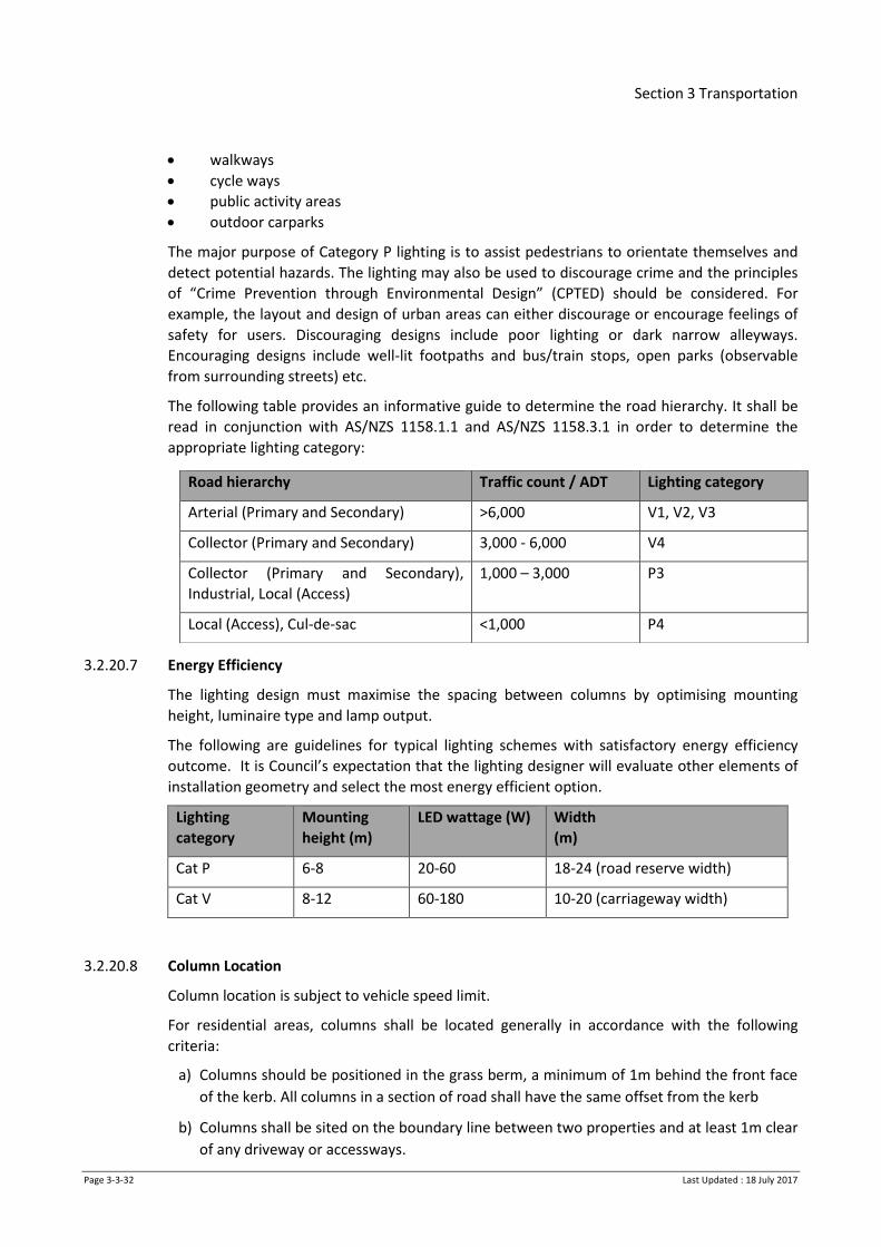
Section 3 Transportation
Page 3-3-32 Last Updated : 18 July 2017
walkways
cycle ways
public activity areas
outdoor carparks
The major purpose of Category P lighting is to assist pedestrians to orientate themselves and
detect potential hazards. The lighting may also be used to discourage crime and the principles
of “Crime Prevention through Environmental Design” (CPTED) should be considered. For
example, the layout and design of urban areas can either discourage or encourage feelings of
safety for users. Discouraging designs include poor lighting or dark narrow alleyways.
Encouraging designs include well-lit footpaths and bus/train stops, open parks (observable
from surrounding streets) etc.
The following table provides an informative guide to determine the road hierarchy. It shall be
read in conjunction with AS/NZS 1158.1.1 and AS/NZS 1158.3.1 in order to determine the
appropriate lighting category:
3.2.20.7 Energy Efficiency
The lighting design must maximise the spacing between columns by optimising mounting
height, luminaire type and lamp output.
The following are guidelines for typical lighting schemes with satisfactory energy efficiency
outcome. It is Council’s expectation that the lighting designer will evaluate other elements of
installation geometry and select the most energy efficient option.
Lighting
category
Mounting
height (m)
LED wattage (W) Width
(m)
Cat P 6-8 20-60 18-24 (road reserve width)
Cat V 8-12 60-180 10-20 (carriageway width)
3.2.20.8 Column Location
Column location is subject to vehicle speed limit.
For residential areas, columns shall be located generally in accordance with the following
criteria:
a) Columns should be positioned in the grass berm, a minimum of 1m behind the front face
of the kerb. All columns in a section of road shall have the same offset from the kerb
b) Columns shall be sited on the boundary line between two properties and at least 1m clear
of any driveway or accessways.
Road hierarchy Traffic count / ADT Lighting category
Arterial (Primary and Secondary) >6,000 V1, V2, V3
Collector (Primary and Secondary) 3,000 - 6,000 V4
Collector (Primary and Secondary),
Industrial, Local (Access)
1,000 – 3,000 P3
Local (Access), Cul-de-sac <1,000 P4

Section 3 Transportation
Page 3-3-33 Last Updated : 18 July 2017
c) In new subdivisions and developments, lighting column positions must be located first to
provide the correct lighting levels in accordance with AS/NZS 1158. Only then should trees
be located. Trees shall not be within 8m of any lighting column. This measurement is
taken from the trunk of the tree.
d) Column offset and location for intersections, bends, road humps and roundabouts is to
comply with relevant requirements of AS/NZS 1158.
e) Pole clearances from overhead low/high voltage conductors shall comply with
requirements of NZECP 34.
3.2.20.9 Traffic Management Devices
Design the lighting of traffic management devices to support the purpose of the device and to
meet the requirements of the relevant AS/NZS 1158 Standard for Category V or Category P
lighting.
3.2.20.10 Pedestrian Refuge Islands
All mid-block pedestrian refuge islands are to be lit by dedicated lights if the current road
lighting levels are not providing the required lux levels of the selected lighting category as
specified in AS/NZS 1158.
Dedicated lighting for pedestrian refuge islands is shown on Drawing D3.11.1 and D3.11.2.
3.2.20.11 Pedestrian Underpasses
Pedestrian Underpasses shall be lit to an appropriate ‘P’ lighting category. All luminaries shall
be resistant to vandalism with an impact rating of IK08 or better. All wiring shall be concealed
with no cabling in surface mounted conduits. Circuits shall be designed so that the underpass
lighting provides a 24hour power supply independent of the street light circuit. LED lighting
must be used.
3.2.20.12 Pedestrian Crossings
Pedestrian crossing lighting shall be designed to AS/NZS 1158, Part 4. Luminaires with specific
photometric distribution must be used.
Belisha beacons or reflective orange discs and white supplementary floodlighting are required
at all crossings.
The general layout of lighting for pedestrian facilities is shown on Drawing D3.11.1 and
D3.11.2.
All pedestrian lighting poles specified to be ‘fold-down’ poles shall have the following:
a) Hinge located 150mm from existing ground level
b) Be electrically safe whilst folded.
c) Latches and safety catch in accordance with Drawing D3.12.2 (as for traffic signals)
d) A lockable switch to be able to operate the lights during day time.
3.2.20.13 Flag Lighting
Lighting of an isolated intersection on an otherwise unlit route with an AADT of >1000, shall be
evaluated/designed in accordance with AS/NZS 1158 Parts 1.1 and 1.3, and NZTA Specification

Section 3 Transportation
Page 3-3-34 Last Updated : 18 July 2017
M30 Road Lighting guidelines. Additional consideration shall be given to roads that are
designated for traffic detours from main highways.
3.2.20.14 Amenity lighting
Lighting for decorative purposes (e.g. up-lights, feature lights) is not permitted in new
subdivisions.
3.2.20.15 Under verandah lighting
Where under-verandah lighting is a Council asset, the impact on such lighting shall be
considered during any demolition or development work on the building shall be carried out in
such way that existing under verandah lighting in the vicinity shall remain connected and
operational.
As built drawings of new or altered connections shall be submitted to the Council. Any
replacement of under verandah lighting will use LED fittings.
3.2.20.16 Private road lighting
Lighting on private roads or ROW is preferred, however will only be permitted if the luminaires
are on a separate metered circuit and a charging agreement is set up with owners and a power
supply company.
These lights will not be the Council’s asset and the maintenance of these lights will be the
owner’s responsibility.
The installation of privately owned road lights will not be permitted on public road reserves.
3.2.20.17 Carpark lighting
For pedestrian safety and security, all outdoor public carparks must be illuminated in
accordance with AS/NZS 1158 requirements for category P.
3.2.20.18 Walkway lighting
The minimum requirement is a light at each end of the walkway to illuminate the end sections.
These lights can be located in the adjacent road reserves provided that they:
a) Operate as a ‘good neighbour’;
b) Are mounted at a sufficient height to prevent vandalism.
For walkways that are not straight, additional lighting in the walkway will be required.
3.2.20.19 Design Drawings and records.
In order to demonstrate compliance and to allow accurate construction all engineering
drawings and documents must show the following information:
a) The extent of the works showing existing and proposed roads and pedestrian areas.
b) Proposed and existing significant road features (e.g. kerbs, property boundaries,
planting, trees, traffic management devices, pedestrian refuge islands and driveway
locations).
c) The road lighting layout showing the following:
Luminaire manufacturer, model and optic
Outreach length and tilt angle
Column manufacturer and type

Section 3 Transportation
Page 3-3-35 Last Updated : 18 July 2017
Luminaire mounting height
Column spacing
Column to kerb offset
d) The lighting design details including:
Design Statement
Computer calculations (LTP analysis information required by AS/NZS 1158)
Luminaire photometric data (in IES or CIE format) including their origin and
maintenance factor
If applicable, site visit records / notes regarding the vicinity of HV/LV overhead
conductors
Manufacturers’ warranty period
3.2.20.20 Design Life
Lighting equipment, including columns, outreach arms, luminaires, LED lamps and coatings,
shall be new and shall have the minimum design lives as set out in NZTA Specifications M26
and M30.
3.2.20.21 Manufacturer’s Warranty Period
Minimum required manufactures warranty period from the date of on-site installation shall be
as set out in NZTA Specifications M26 and M30.
The warranty must be transferable to the Council upon vesting.
3.2.20.22 Approved Columns
For V (Arterial / Collector) category roads, all columns shall have the following:
Galvanised, non-painted steel octagonal columns, compliant with NZTA Specification
M26 and M26A.
Either curved or elliptical outreach arms.
A corrosion protective coating in ground sections, extending 100mm above the finished
ground level.
Be ground planted unless shear base installation is specifically requested by the Council.
For P category (Local roads), all columns shall have the following:
A steel column; finish can be galvanised, black or Brunswick green.
Comply with the relevant NZTA specification M26.
Cost of the proposed column to be no greater than 2.5 times cost of equivalent
galvanised steel octagonal column
A lead- in time that is no greater than 6 weeks
Have either curved or elliptical outreach arm. Arch type are not permitted (bracket
attached to top of luminaire).
An opening for access to control gear no smaller than 100x150 mm fitted with a suitable
waterproof cover or door. The opening shall be positioned 500-1200mm above ground
level. The cover shall be secured by tamper proof bolts.
3.2.20.23 Approved Luminaires
Luminaires shall be of the LED type and shall comply with the requirements of NZTA
Specification M30.

Section 3 Transportation
Page 3-3-36 Last Updated : 18 July 2017
The Council will accept only luminaire units from the NZTA Specification M30 approved list
which meet the following criteria:
Lead-in time for luminaire is no greater than 6 weeks
Lead-in time for spare parts is no greater than 3 weeks
Maximum total weight is no greater than 12 kg
Initial Lumen to system wattage ratio is 90 or greater
Power factor shall be 0.9 or greater
An adjustable tilt/mechanism of +5° or -10° in incremental steps of 5° is desirable.
Refer to NZTA specification M30 for the latest list of accepted luminaires.
3.2.21 Special Vehicle lanes
Where special vehicle lanes are required, they shall have appropriate signage, road markings
and coloured surfacing.
Special Vehicle Lanes include the following:
a) Bus and electric vehicle lanes
b) Transit lanes - urban
c) High Occupancy Vehicle (HOV) Lanes
3.2.22 Traffic Control Devices – Line Marking and Signs
The design shall incorporate all required road marking, signs, and other facilities appropriate to
the place and link context. Local roads should be designed to minimise the need for traffic
signs and marking.
Designs shall satisfy the Land Transport Rule: Traffic Control Devices 2004, associated NZTA
Traffic Control Devices Manuals, NZTA Pedestrian Planning and Design Guide and NZTA Cycling
Network Guidance – Planning & Design Guide.
All proposed road markings, signs and other traffic control devices shall be shown on the plans
and approved by Council.
3.2.23 Feature Entrance Walls, Berm and Street Furniture
The designer is to ensure that the resulting visual impact of walls, structures, street art, street
furniture etc achieve good urban design visual outcomes. Refer to the relevant District Plan
and any relevant policy and structure plan documents; early consultation with Council is
encouraged.
3.2.23.1 Street Furniture
Seats, litterbins and other street furniture shall be designed and placed in accordance with the
specifications set out in section 3.3.11.
Furniture used shall be compatible with existing street furniture, unless expressly approved
otherwise by Council.
3.2.23.2 Feature Walls
Feature Walls are not permitted within the transportation corridor.

Section 3 Transportation
Page 3-3-37 Last Updated : 18 July 2017
3.2.23.3 Berm Furniture
With the exception of approved litter bins, seats, fences and bollards, structures or features
which are not part of signage or traffic control are not permitted in the Transportation
Corridor, unless as part of a structure plan or in accordance with any relevant Council arts or
other policy. Prior to installation and design, consultation is required with Council to ensure
safety of road users is not compromised.
3.2.24 Safety Barriers
3.2.24.1 Pedestrian and Cycle Barriers
Where a footpath or other public access bounds or is adjacent to a steep bank, wall, culvert or
other such feature, safety barriers for pedestrian and cyclists are necessary. All barriers shall
comply with the design requirements of NZS/AS 1657 : Fixed Platforms, Walkways, Stairways
and Ladders - Design, Construction and Installation and, where relevant, the New Zealand
Building Code, Clause F4.
3.2.24.2 Vehicle Barriers
Alternative engineering measures shall be considered prior to the installation of roadside
barriers.
Alternative engineering measures that improve the information that road users receive from
the road environment shall be considered prior to the installation of a roadside barrier include,
but are not limited to:
a) Relocation or modification of hazardous objects
b) Marking of hazardous objects
c) Road geometry and pavement surface
d) Pavement markings
e) Reflective raised pavement markers
f) Street lighting
g) Permanent warning signs
h) Chevron sight boards
i) Frangible sight rails
j) Ground modelling and planting
Where safety barriers for vehicles in urban areas are necessary, they shall comply with the
design requirements of NZTA RTS 11: Urban Roadside Barriers and Alternative Treatments.
Where safety barriers for vehicles in rural areas are necessary, they shall comply with the
design requirements in AS/NZS 3845 : Road Safety Barrier Systems.
3.2.25 Fencing
Refer to Landscape Section for fencing requirement styles.
3.2.26 Trees and Landscaping
Refer to Landscape Section for details on trees and landscaping in transport corridor.
Section 3 Transportation
Page 3-3-38 Last Updated : 18 July 2017
3.2.27 Structures and Underpasses
3.2.27.1 Bridges and Large Culverts
For any project where a bridge is proposed, the bridge concept plan must be discussed and
agreed with Council before detailed design commences.
Bridges and culverts may require separate resource and building consents. All bridges and
culverts shall be designed in accordance with the NZTA Bridge Manual (SP/M/022).
Particular features that are to be considered/covered in the design shall include, but are not
limited to:
a) Widths/lengths
All bridges and culverts shall be designed with a width to accommodate movement lanes,
cycle, and pedestrian needs of the road, in accordance with the relevant District Plan.
b) Safety barriers
The design of the structure shall provide for the installation and fixing of all suitable
barriers to cater for the needs of pedestrians, cyclists and vehicles, including the
interaction between the various modes.
c) Batter slope protection
All culverts shall have anti-scour structures to protect batter slopes, berms, and
carriageways.
d) Clearance over traffic lanes
Where passing above traffic lanes, bridges shall have a full clearance height of 5.2m. The
bridge shall be signed to highlight the maximum safe design vehicle height.
e) Foundations
All bridges and culverts shall be founded to resist settlement or scour. Abutments shall be
designed to ensure bank stability and provide erosion or scour protection as applicable.
f) Provision for services
The provision of the structure for use as a service corridor shall be included in the design.
This shall include consultation with utility providers to ascertain their current and future
needs.
g) Waterway design
Refer to the Stormwater Section.
h) Inspection and maintenance
The design shall include provision of any necessary access facilities to and within the
structure in order to undertaken inspection and maintenance activities.
All of these features shall be documented in the Design and Access Statement submitted
at the time of the Engineering plans.
3.2.27.2 Pedestrian Underpasses
Pedestrian underpasses may be required in locations where high traffic and risks to pedestrian
safety has been identified and maybe required as part of a structure plan walking/cycling
strategy/policy. Underpasses will be required to have adequate width and height and access
Section 3 Transportation
Page 3-3-39 Last Updated : 18 July 2017
provisions which allow full use of pedestrians, mobility scooters, wheelchair access, visually
impaired pedestrians and cyclists.
Underpasses will provide sufficient natural and artificial lighting so as not to create un-
desirable dark places, designs must take into account stormwater disposal, and pumping
stations are not permitted due to on-going maintenance issues.
Careful consideration to visual design outcomes is required; the design of wing walls,
underpass structure, stairs, ramps etc., is to result in good urban design visual outcomes and
compliance with CPTED principles.
Pedestrian underpass walls to be painted in ‘Hit Grey’ or other colour required by the relevant
Council, and lighting shall be in accordance with the requirements set out in clause 3.2.20.11
above.
3.2.27.3 Retaining Walls
Retaining walls which are located within the Transportation Corridor will likely require a
building consent; retaining wall designs which have been undertaken by a suitably qualified
engineer will be required.
3.2.28 Traffic Signals
Traffic signal installations are to be designed in accordance with Austroads Guide to Traffic
Management Part 10: Traffic Control and Communication Devices.
Refer also to Section 3.6 Traffic Signals.
3.2.29 Traffic Calming Devices
In order to achieve the desired design speed environment, traffic calming devices may be
required within the transportation corridor. Austroads Guide to Traffic and The Traffic Control
Devices Manual should be used to guide development of these devices.
Standard details are provided for the following devices:
Roundabouts – mini asphaltic concrete D3.10.1
Paved raised pedestrian ramp D3.10.5 and D3.10.6
3.2.30 Over-Dimensional Vehicle Routes
The Council may specify over-dimensional vehicle routes in its transportation/traffic bylaws.
When completing any improvements or changes to infrastructure the clearance requirements
for over-dimensional vehicles (and their loads) shall be taken into account. Reference shall be
made to applicable standard and consultation undertaken with the Heavy Haulage Association
to confirm appropriate provisions are provided.
3.3 Construction
3.3.1 Pavement Materials
This section covers the methods, specifications and materials to be used when constructing
transportation assets.
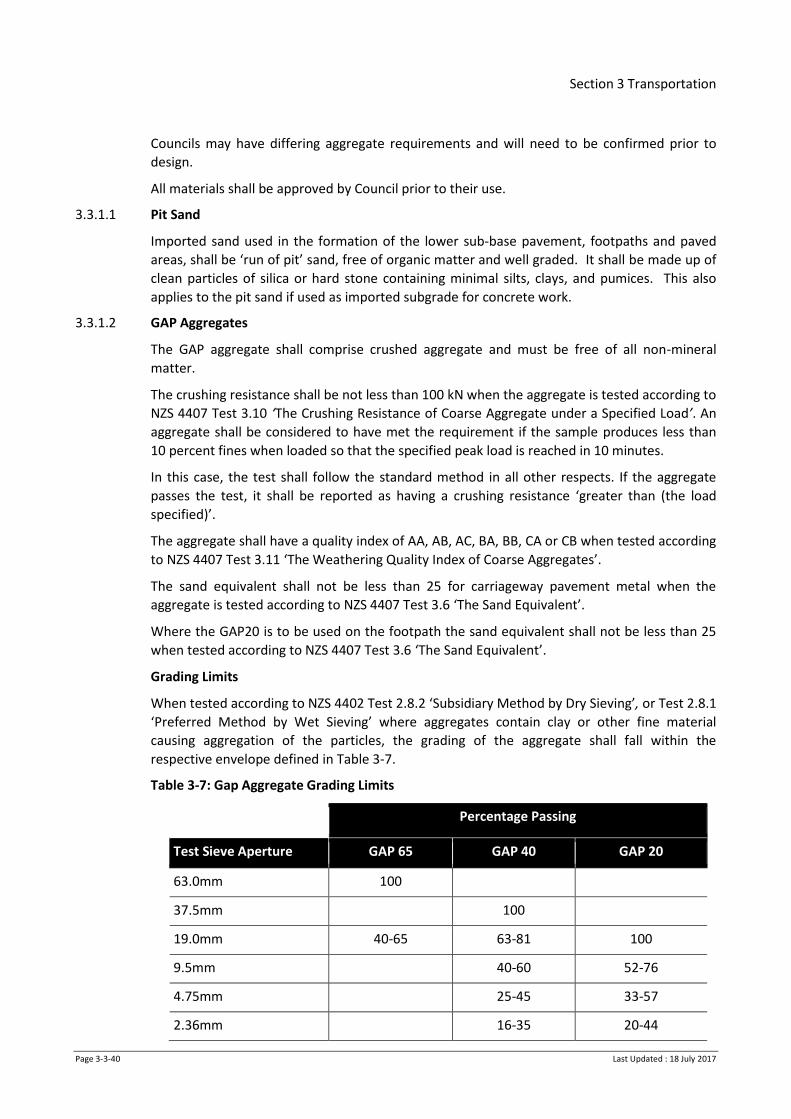
Section 3 Transportation
Page 3-3-40 Last Updated : 18 July 2017
Councils may have differing aggregate requirements and will need to be confirmed prior to
design.
All materials shall be approved by Council prior to their use.
3.3.1.1 Pit Sand
Imported sand used in the formation of the lower sub-base pavement, footpaths and paved
areas, shall be ‘run of pit’ sand, free of organic matter and well graded. It shall be made up of
clean particles of silica or hard stone containing minimal silts, clays, and pumices. This also
applies to the pit sand if used as imported subgrade for concrete work.
3.3.1.2 GAP Aggregates
The GAP aggregate shall comprise crushed aggregate and must be free of all non-mineral
matter.
The crushing resistance shall be not less than 100 kN when the aggregate is tested according to
NZS 4407 Test 3.10 ‘The Crushing Resistance of Coarse Aggregate under a Specified Load’. An
aggregate shall be considered to have met the requirement if the sample produces less than
10 percent fines when loaded so that the specified peak load is reached in 10 minutes.
In this case, the test shall follow the standard method in all other respects. If the aggregate
passes the test, it shall be reported as having a crushing resistance ‘greater than (the load
specified)’.
The aggregate shall have a quality index of AA, AB, AC, BA, BB, CA or CB when tested according
to NZS 4407 Test 3.11 ‘The Weathering Quality Index of Coarse Aggregates’.
The sand equivalent shall not be less than 25 for carriageway pavement metal when the
aggregate is tested according to NZS 4407 Test 3.6 ‘The Sand Equivalent’.
Where the GAP20 is to be used on the footpath the sand equivalent shall not be less than 25
when tested according to NZS 4407 Test 3.6 ‘The Sand Equivalent’.
Grading Limits
When tested according to NZS 4402 Test 2.8.2 ‘Subsidiary Method by Dry Sieving’, or Test 2.8.1
‘Preferred Method by Wet Sieving’ where aggregates contain clay or other fine material
causing aggregation of the particles, the grading of the aggregate shall fall within the
respective envelope defined in Table 3-7.
Table 3-7: Gap Aggregate Grading Limits
Percentage Passing
Test Sieve Aperture GAP 65 GAP 40 GAP 20
63.0mm 100
37.5mm 100
19.0mm 40-65 63-81 100
9.5mm 40-60 52-76
4.75mm 25-45 33-57
2.36mm 16-35 20-44
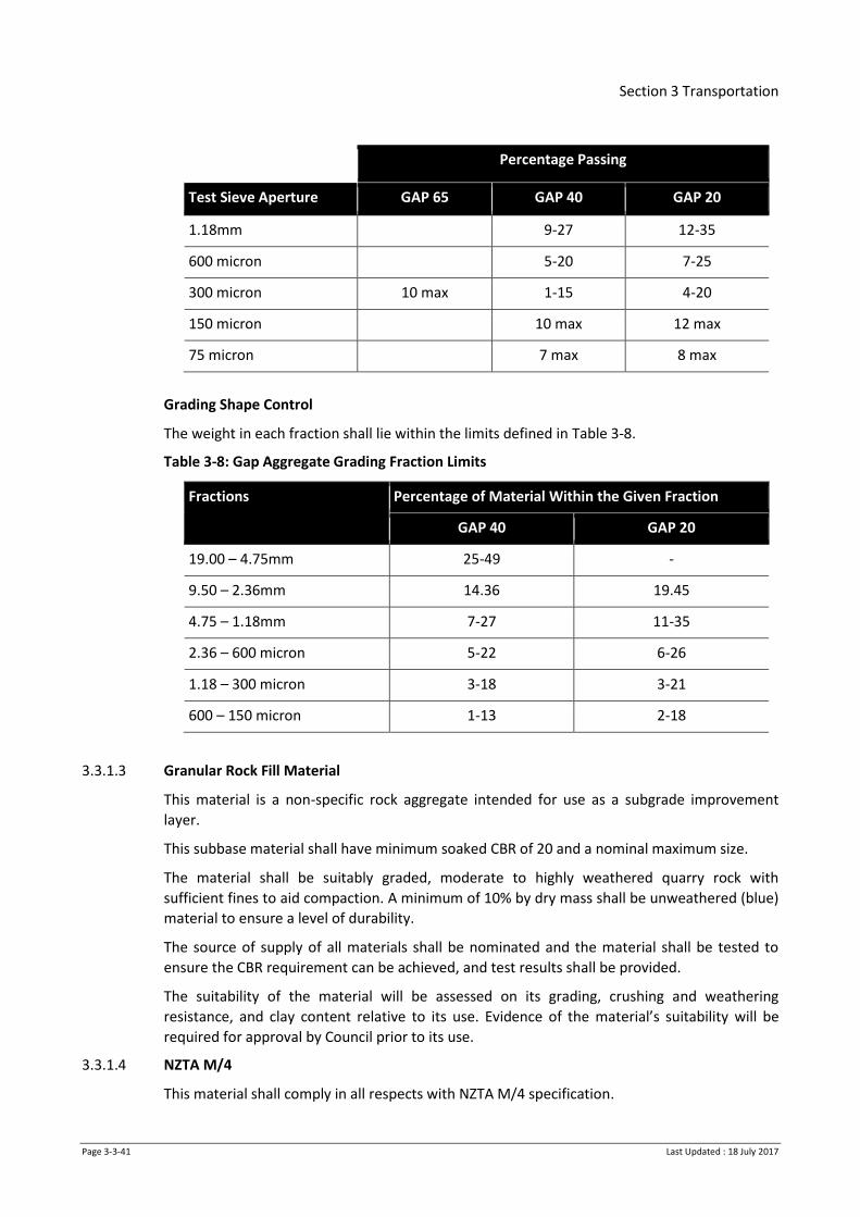
Section 3 Transportation
Page 3-3-41 Last Updated : 18 July 2017
Percentage Passing
Test Sieve Aperture GAP 65 GAP 40 GAP 20
1.18mm 9-27 12-35
600 micron 5-20 7-25
300 micron 10 max 1-15 4-20
150 micron 10 max 12 max
75 micron 7 max 8 max
Grading Shape Control
The weight in each fraction shall lie within the limits defined in Table 3-8.
Table 3-8: Gap Aggregate Grading Fraction Limits
Fractions Percentage of Material Within the Given Fraction
GAP 40 GAP 20
19.00 – 4.75mm 25-49 -
9.50 – 2.36mm 14.36 19.45
4.75 – 1.18mm 7-27 11-35
2.36 – 600 micron 5-22 6-26
1.18 – 300 micron 3-18 3-21
600 – 150 micron 1-13 2-18
3.3.1.3 Granular Rock Fill Material
This material is a non-specific rock aggregate intended for use as a subgrade improvement
layer.
This subbase material shall have minimum soaked CBR of 20 and a nominal maximum size.
The material shall be suitably graded, moderate to highly weathered quarry rock with
sufficient fines to aid compaction. A minimum of 10% by dry mass shall be unweathered (blue)
material to ensure a level of durability.
The source of supply of all materials shall be nominated and the material shall be tested to
ensure the CBR requirement can be achieved, and test results shall be provided.
The suitability of the material will be assessed on its grading, crushing and weathering
resistance, and clay content relative to its use. Evidence of the material’s suitability will be
required for approval by Council prior to its use.
3.3.1.4 NZTA M/4
This material shall comply in all respects with NZTA M/4 specification.

Section 3 Transportation
Page 3-3-42 Last Updated : 18 July 2017
3.3.2 New Pavement Construction
3.3.2.1 Subgrade Layer
Use of stabilisation additives in the subgrade is subject to specific design and council approval
(see section 3.2.12.1) as follows:
a) The subgrade layer shall be constructed to meet the requirements of the pavement design
and NZTA’s Specification F/1 : Earthworks Construction. Wherever possible, the natural
insitu material shall be used in construction of the subgrade by implementing compaction
or other methods of modification to meet the required subgrade strength. Where the
insitu material is unsuitable to be used as subgrade, or is otherwise excluded from use, it
shall be replaced by imported subgrade material. The imported subgrade material for the
pavement shall be fit for purpose and shall be subject to approval by Council before use.
Options may include ‘run of the pit’ sand, selected quarry run rock or other material
approved by Council. The suitability of alternatives will need to be demonstrated.
b) The subgrade material, whether insitu or imported, shall be compacted to a depth of not
less than 600mm. It shall be placed in layers not exceeding 150mm (compacted thickness)
and as close as practicable to optimum moisture content. The material shall be compacted
to the specified CBR value. Measurement of CBR value shall be by CBR insitu tests or, in
the case of non-cohesive material, by a suitable calibrated Scala Penetrometer test.
c) For cohesive soils, the Scala Penetrometer test may be used as a measure of uniformity.
Irrespective of the CBR and Benkelman Beam results, the standard of compaction shall not
be less than 95% of the optimum dry density of the material as specified in NZS 4402 Test
4.1.1 or Test 4.1.3.
d) The entire surface of the compacted subgrade shall be made smooth, firm and uniform, by
blading, grading and rolling, approximating the crossfall required on the final surface. The
reduced level of any point shall be within the limits 0mm above to 20mm below the
designed or nominated level, as establish by stringing. The surface shall be finished so that
all points are within 15mm below a 3.0m straight edge laid at any point on the surface. See
section 3.7.2 for testing requirements.
e) Compaction shall cease if the material shows signs of excessive weaving or heaving and
shall not recommence until the problem has been resolved.
f) If the compaction of the subgrade layer does not meet the required criteria then the
following options are available for consideration
i. The Contractor may opt to carry out further compaction to achieve the required
level of compaction, or
ii. Council may choose to replace not less than 100mm compacted depth of the
subgrade layer with subbase metal. Once compacted, the surface shall be trimmed
to grade and retested to prove the required strength has been achieved, or
iii. The Contractor may, subject to the approval of Council, opt to correct the non-
compliance of the subgrade by means of one of the following remediation
methods:
the use of geogrid and/or geofabric;
Section 3 Transportation
Page 3-3-43 Last Updated : 18 July 2017
stabilisation of the subgrade;
stabilisation of the subbase aggregate;
stabilisation of the basecourse aggregate; or
a combination of the above.
It should be noted that approval by Council of the application of one or more of the above
options does not relieve the Developer/Contractor of responsibility for attaining the required
final pavement strength.
Note: extended exposure of the subgrade to wet weather causes degradation of the subgrade’s
performance, the entire surface of the subgrade should be protected to ensure it is smooth,
compacted, firm and uniform.
3.3.2.2 Recovered Material
Recovered material may be specified for use as the subbase layer for the construction of a new
pavement, subject to prior approval by Council.
Where recovered material is to be used and there is a shortfall, the recovered material shall be
placed first with the imported aggregate to make up the shortfall placed on top, subject to
suitable depths of each being achievable for effective compaction.
Recovered road pavement for reuse shall have a grading curve within or close to (+/- 3% at any
sieve size) the grading of the specified sub-base aggregate.
Recovered material with obvious clay intrusions shall not be used in the sub-base.
No seal or asphalt from the old pavement shall be included in the recovered material to be
used.
Other than the recovered materials consequential characteristics, the pavement layer shall be
prepared as specified.
3.3.2.3 Subbase Layer
NZTA’s Specification B/2 : Construction of Unbound Granular Pavement Layers shall apply
except where modified by the following:
a) The subbase layer shall be constructed to the final shape shown on the accepted
Construction Drawings
b) No subbase layer material shall be placed until the subgrade has been satisfactorily
completed and approved by Council
c) The reduced level of any point on the surface of the subbase layer shall be within the
limits 10mm above to 10mm below the designed or nominated level as establish by
stringing
d) The surface shall be finished so that all points are within 15mm below a 3m straight edge
laid at any point on the surface
e) The subbase (and basecourse if applicable) beneath the kerb and channel must extend at
least 400mm beyond the back of the kerb. See drawing D3.3.6.
3.3.2.4 Basecourse Layer
NZTA’s Specification B/2 : Construction of Unbound Granular Pavement Layers shall apply
except where modified by the following:

Section 3 Transportation
Page 3-3-44 Last Updated : 18 July 2017
a) The basecourse layer shall be constructed to the final shape shown on the accepted
Construction Drawings
b) No basecourse layer material shall be placed until all previous pavement layers have been
satisfactorily completed and approved by Council
c) The tolerances and testing requirements as described in section 3.7.2.
3.3.3 Ripping and Cement Stabilisation
Construction of any stabilised pavement layers shall be in accordance with NZTA Specification
B/5 : In-Situ Stabilisation of Modified Pavement Layers. Council approval is required for use of
stabilisation techniques, see section 3.2.12.1.
3.3.4 Testing
The pavement layers shall be tested and each layer approved by Council before construction of
subsequent layers begins. For details of the testing and tolerances required, see section 3.7.2.
3.3.5 Concrete Works
This section covers all concrete work for footpaths, various kerbing, kerb and channel,
catchpits and vehicle crossings. These shall all be formed to the dimensions shown in the
Drawings (D3.3.1, D3.3.2, D3.3.3, D3.3.5 and D3.3.7).
3.3.5.1 Formwork
Where not covered in this specification, formwork shall generally comply with the
requirements of NZS 3109.
Wherever necessary, formwork shall be used to support and confine the concrete and shape it
to the required dimensions. Joints and linings shall be sufficiently tight to prevent loss of water
from the concrete.
All timber for formwork shall be of an approved quality and type. For kerbs and channels
formwork shall be ex 40mm material provided that 15mm timber or other suitable material
may be used on short radius curves.
Formwork shall be of a sufficient depth to fully support all vertical faces. Where it supports
exposed surfaces, formwork shall be long lengths dressed smooth on one face and both edges.
Timber strips for chamfers shall be machined all round to be true to shape and form and they
shall be kept in good order. Alternatively the chamfer or bullnose may be formed with a
specific floating tool or dressed fillets.
Steel forms shall be of approved design and shall be maintained in good condition. The joints
between lengths shall be secured accurately during concreting to maintain a good line in the
finished work.
Forms shall be designed to be easily removable without damaging the green concrete and shall
be kept thoroughly clean and oil or wax dressed to prevent adhesion of concrete or rust
staining. Forms for curved kerbs shall be brought to a true curve by springing the timber
evenly.
The shape, strength, rigidity, mortar tightness and surface smoothness of re-used forms shall
be maintained at all times. Warped or bulged timber is not permitted. Timber which has been

Section 3 Transportation
Page 3-3-45 Last Updated : 18 July 2017
used shall have the surfaces which are to be in contact with the concrete thoroughly cleaned
and treated before being used again.
3.3.5.2 Concrete Mix and Proportions
Concrete mixes shall be proportioned to be workable, capable of being thoroughly
consolidated by the means of compaction available and to provide the specified strength of
concrete. The concrete may be either ordinary grade, high grade or special grade as defined in
NZS 3109.
The concrete used shall be either mixed on the site or supplied ready-mixed. In every case, the
concrete production shall be in accordance with NZS 3104 : Specification for Concrete
Production.
The strength of concrete as defined in NZS 3109 shall be 28-day cured in-place minimum
strength 20 MPa for all the above works.
3.3.5.3 Placing Concrete
The Contractor shall give due notice to Council of the time it is intended to place any concrete
and no concrete shall be placed until approval has been obtained from Council.
Concrete shall not be placed on frozen ground nor shall it be placed in unfavourable
conditions, which may be detrimental to the quality and finish of the concrete. Unfavourable
conditions shall be deemed to include low temperatures (below 5°C with temperature
descending, or below 2°C with temperature ascending), excessively hot, dry conditions,
excessively wet conditions, or any conditions making it impractical to work and finish the
concrete adequately.
Immediately before placing the concrete, the foundations shall be lightly dampened, and
formwork shall be cleaned out. In all cases surplus water shall be removed before concrete is
placed.
The concrete shall be placed so the coarse aggregate does not separate from the fines, and it
shall be thoroughly worked and consolidated into all parts of the formwork, so that no voids or
cavities are left. All concrete shall be handled from the mixer, or from the agitator truck mixer,
to the place of final deposit as rapidly as is practicable, by methods which prevent segregation.
Unless otherwise approved, in no case shall more than 30 minutes elapse between discharge
of concrete from the mixer/agitator truck and final placement. Under no circumstances shall
partially hardened concrete be placed in the work.
Where a channel is finished with a sand/cement mortar coat, the mortar shall be placed within
two hours of placing the concrete, provided that when hot dry conditions are prevailing, the
allowable time shall be reduced to 1 hour.
If for any reason a delay of more than 2 hours occurs, an approved PVA bonding agent shall be
used to ensure the mortar is adequately bonded to the concrete.
Before fresh concrete is placed upon or against any concrete which has already hardened, the
surface of the hardened concrete shall be thoroughly scabbled, cleaned and cleared of all
laitance, loose or foreign material.
3.3.5.4 Reinforcement
All reinforcement other than ties and stirrups shall be deformed unless otherwise detailed. The
length of lapped splices (without hooks) shall be not less than 32 bar diameters in length.

Section 3 Transportation
Page 3-3-46 Last Updated : 18 July 2017
Steel reinforcement, at the time the concrete is placed, shall be free from loose flaky rust,
mud, oil or other coatings that will destroy or reduce the bond.
Reinforcement shall be accurately placed, adequately supported and secured against
displacement before or during concrete placement.
The minimum cover to all main reinforcing steel shall be 50mm unless otherwise specified.
3.3.5.5 Curing Of Concrete
Strict attention shall be paid to adequate curing, which is an important factor in attaining the
required strength for the concrete.
Immediately after placement, concrete shall be protected from premature drying, excessively
high or low temperatures and mechanical damage and shall be maintained with minimal
moisture loss for the necessary curing period and hardening of the concrete. In hot dry
weather sprinklers or damp covers will need to be used.
All concrete surfaces not in contact with formwork shall be cured by the application of a curing
compound conforming to the specification ASTM C309 : Specification for liquid membrane -
forming compounds for curing concrete.
In cold or wet weather, concrete shall be protected from the elements during the curing
period by covering with sheets of PVC or alternative approved material.
3.3.5.6 Machine Laid Kerb and Channel
Contractors who intend to construct the kerbs and channels by using an extrusion machine will
be required to use ready mixed concrete from a certified plant. The concrete provided shall be
designed so that after placement it will accurately retain its shape and present a good surface.
Certification of the concrete supplied is required. No subsequent cement washing will be
permitted. The machine shall be capable of providing well compacted concrete with the
absence of trapped air.
The machine shall not be used to pour curves with radii less than 5m. For these curves the
Contractor shall use formwork as specified.
A properly shaped screed shall be used in forming cut downs.
3.3.5.7 Finished Work
Methods shall be used that will provide a smooth, clean and even surface on the exposed faces
of all concrete work. These methods shall also put the required finish directly on the structural
concrete without the use of mortar renderings, provided that, if specific prior approval of
Council is obtained, the channel may be finished with a layer of separately applied mortar. In
such a case, the mortar shall consist of not more than 2 parts of approved sand to 1 of cement.
It shall be nominally 6mm in thickness and shall be placed before the initial set of the concrete
and within 2 hours of placing the concrete.
Alternatively, a mortar layer to the above consistency may be applied in conjunction with the
laying of the kerb and channel if the kerb and channel is laid by machine and the machine is
designed for such use.
The top and face of the kerb and the channel surface shall be floated over with a steel tool
before the mortar has finally set. No depressions which may hold water will be permitted.
The surface finishes of all kerb and channel, whether machine laid or hand laid, shall be
uniform in colour, texture and shape.
Section 3 Transportation
Page 3-3-47 Last Updated : 18 July 2017
3.3.5.8 Contraction/Expansion Joints
Contraction/Expansion joints shall be formed or cut along the kerb at a maximum spacing of
3.0m. The slot shall penetrate the concrete by not less than 50mm and the mortar dressed
over the cut face. The contractor shall ensure that cold joints are accurately marked so that
the subsequent saw cut is in the cold joint. Should cracking occur adjacent to the saw cut a
minimum section of 1.5 metres of kerb and channel shall be removed and re-cast.
3.3.5.9 Backfilling against Concrete Work
Backfilling against the kerb and channel or any other concrete structure shall take place as
soon as practicable after the concrete has reached sufficient strength, with particular emphasis
at curves, corners, intersections and pedestrian kerb crossings but not prior to 36 hours after
pouring.
Care shall be taken to ensure that no damage is done to the path, crossing, kerb and channel
or other concrete structure when placing and compacting the backfill.
3.3.5.10 Surface Finish (Footpath and Vehicle Crossing Areas)
All final path and vehicle crossing surfaces shall be true to the lines and levels Specified and
‘broom’ finished. Design considerations aside, the final surface shall not vary by more than
5mm when checked with a 3m straight edge. No finished surface shall hold water.
3.3.6 Road Stormwater Drainage (Kerb, Channel and catchpits) Construction
3.3.6.1 Kerb and Channel in Existing Pavement
Prior to work commencing, the lengths of kerb and channel that are to be removed shall be
marked on site and agreed with Council.
3.3.6.2 Saw Cutting
Prior to removal, the kerb and channel shall be cut vertically and at right angles to the
alignment to ensure a clean break. The existing sealed surface shall be cut parallel to and at a
distance of 500mm, or greater if required, from the existing channel lip. The seal shall also be
cut perpendicular to the kerb from the vertical saw cut to the parallel seal cut.
If the kerb and channel to be removed abuts any berm seal (e.g. sealed footpath), the sealed
surface shall be saw cut within 5 days, at a distance behind the kerb face suitable for
reinstatement.
3.3.6.3 Excavation to Pavement Depth
After saw cutting, the kerb and channel and pavement shall be excavated to the proposed
pavement depth or deeper if required. The sides of the excavated area shall be trimmed to be
as near as possible to vertical. Care shall be taken to ensure that undermining and/or over
break does not occur during excavation. All waste material including the old kerb and channel
shall be removed from the site and appropriately disposed of.
3.3.6.4 Subgrade Preparation
The exposed subgrade (at the required depth), shall be tested using a standard Scala
Penetrometer refer to section 3.7.3. The prepared subgrade shall be compacted to the CBR
specified. If the material fails this initial test it shall either be:
a) Further compacted, if the material is suitable, to improve the CBR value, or

Section 3 Transportation
Page 3-3-48 Last Updated : 18 July 2017
b) Excavated and removed from site, then backfilled with pitsand and compacted to the
subgrade level.
All pitsand backfill shall be compacted in lifts of not more than 100mm. The subgrade area
either insitu or imported shall be trimmed and shaped to accommodate the specified lines and
levels given and compacted to provide uniform support for the pavement course.
All tree roots found in the subgrade or pavement area during excavation shall be removed
(subject to Council Arborist approval) and are to be severed 0.5m behind the back or front of
the kerb and be removed off site. Any root greater than 50mm in diameter shall be cleanly saw
cut. No such roots shall be cut without the prior approval of Council if they are within the
dripline of the tree.
Note: extended exposure of the subgrade to wet weather causes degradation of the subgrade’s
performance, the entire surface of the subgrade should be protected to ensure it is smooth,
compacted, firm and uniform.
3.3.6.5 Kerb and Channel Foundation
After the subgrade has been approved, a compacted layer of GAP40 75mm deep shall be
placed. Compaction shall be to refusal. The surface of the GAP40 shall be smooth and uniform,
suitable for the placing of the kerb and channel concrete.
3.3.6.6 Kerb and Channel Placing
Refer Clause 3.2.14.2 for details on concrete placement.
3.3.6.7 Joining to Carriageway
After the kerb and channel concrete has reached sufficient strength, the carriageway shall be
married into the existing carriageway (with banding) and new kerb and channel lip. If not
already achieved during the kerb base construction, the carriageway shall be excavated to the
existing subgrade and at least 200mm deep at the channel face. The excavation base shall be
flat and level up to the edge of the saw cut seal. All excavated faces shall be vertical.
The subgrade shall be compacted to a CBR of at least 10. The basecourse metal (NZTA M/4 or
GAP40) shall be placed on the prepared subgrade in layers not exceeding 150mm and
compacted to refusal. The depth of basecourse is dependent on the surfacing, either asphalt or
chip seal, but not less than 200mm (i.e. 25mm of asphalt surfacing).
3.3.6.8 Kerb and Channel in New Pavement
In accordance with clause 3.3.5.6, except all references to carriageway protection and
reinstatement shall not be required for this activity.
3.3.6.9 Catchpits
Refer to stormwater Section for details; the details also show a list of the permitted precast
components.
The construction specification described in Stormwater Section.
Catchpits shall be accurately positioned so that the grate and kerb block fit neatly into the kerb
and channel. Rectangular pits shall be oriented with the longer side parallel to the kerb. Grates
are to be cycle friendly.

Section 3 Transportation
Page 3-3-49 Last Updated : 18 July 2017
3.3.6.10 Subgrade Drainage
Refer to Drawing D3.4.1 for details. NZTA specifications F/2 : Pipe Subsoil Drain Construction
and F/5 : Corrugated Plastic Pipe Subsoil Drain Construction shall apply.
Where subsoil drains are required, as shown on the Drawing or directed by Council, they shall
be placed behind the kerb unless shown or directed to be in front of the kerb.
The subsoil drains shall consist of an approved filter drainpipe, 100mm to 150mm diameter, or
equivalent, in a trench backfilled with an approved filter material around the conduit. The
conduit shall have a grade not less than 1 in 200 to discharge into the catchpit.
3.3.6.11 Additional Subsoil Drainage
Where directed, any permanent wet spot in the subgrade shall be drained to the subsoil drain.
Where the wet area is below the level of the subsoil drain, it shall be drained by connecting to
the nearest stormwater system.
3.3.6.12 Other Requirements
NZTA F/2 filter material shall not be used as a filter material in close proximity to HDPE slotted
pipe. Unless otherwise designed and approved by Council, pea-metal shall be for backfilling
around HDPE slotted pipe. Where backfilling a subsoil drain with filter material the minimum
cover shall be 100mm. Where a strip drain is approved, backfill is to be permeable sand.
The invert of subsoil pipes at the catchpit shall not be less than 100mm above the invert of the
catchpit outlet.
3.3.7 Road Surfacing Construction
The relevant NZTA specifications listed in Clause 3.1.2 shall apply to road surfacing procedures
and materials.
Exceptions to the specifications include:
All references to the basis of payment contained within the specifications are deleted;
Reference to the Contractor's obligation with respect to the foreshortening of the
maintenance requirements of the seal coat (NZTA P/3 & P/4) is deleted;
Application rates, cutback percentage and the percentage of adhesion agent is to be specified
by the Developer/Contractor, and forwarded to Council with design calculations for approval
at least 24 hours prior to application.
For both first and second coat chip seal, the bitumen application shall extend over the lip of
the kerb and channel, but not by more than 25mm.
3.3.7.1 Waterproofing First Coat Chip Seal
A two coat chip seal shall be applied to the prepared basecourse surface but only when the air
temperature is greater than 10oC in the shade as detailed in the NZTA P/3.
The first layer shall consist of the supply and spraying of 180/200 penetration grade bitumen.
The bitumen shall be cut back to suit, include one part per hundred (p.p.h) adhesion agent and
be spread at a rate of 1.2 litres/m2 residual (measured at 15oC).
The first layer chip shall include the supply, spreading and rolling of Grade 3 chip at a spread
rate of 75 m2/m3. It is essential that the spreading of the first chip layer is carefully controlled
such that the chips are evenly spread and are no more than one layer thick over the entire
surface.

Section 3 Transportation
Page 3-3-50 Last Updated : 18 July 2017
The second layer shall consist of the supply and spraying of 180/200 penetration grade
bitumen. The bitumen shall be cut back to suit, include one pph adhesion agent and be spread
at a rate of 0.8 litres/m2 residual (measured at 15oC).
The second layer of chip shall include the supply, spreading and rolling of Grade 5 chip at a
spread rate of 150 m2/m3.
Refer to ‘Removal of Surplus Chip’ in following clause.
3.3.7.2 Chip Seal Resealing
This treatment shall be applied on carriageways to produce a uniform texture on surfaces that
have an existing seal coat and potentially repair patches.
Prior to resealing all surfacing and pavement defects must be repaired. The resealing shall not
be applied until 28 days after asphalt patching or levelling has been completed, or the
basecourse repairs have been two-coat sealed.
The second coat chipseal carried out between 3 and 18 months after the waterproofing first
coat shall consist of supply and spraying of 180/200 penetration grade bitumen. The bitumen
shall be cut back to suit, include 1 pph adhesion agent and be applied at the rate of 1.3
litres/m2 residual (measured at 15°C). The chip layer shall consist of the supplying, spreading
and rolling of Grade 5 chip. If specified, a dry locking coat of Grade 5 or 6 chip shall then be
supplied and applied at a rate of 300 m2/m3.
Removal of Surplus Chip
When the sealed surface is to be opened to traffic, all surplus chip shall be removed within 48
hours of the completion of rolling. For sites that are not open to normal traffic, chip sweeping
may be delayed but must be completed before opening the road to normal traffic.
All surplus chips shall be removed from grass berms, driveways, parking areas and footpaths.
Follow up sweeps will be required to ensure that all loose chip is collected and removed from
the site for a period of one month following chip application.
3.3.7.3 Asphaltic Concrete
Where design traffic volumes in residential areas are less than 800 vehicles per day, and there
are no additional turning stresses created by intersections, a single coat grade 5 membrane
seal shall be used with a residual bitumen application rate of 1 L/m².
Where traffic volumes are higher or there are greater stresses, a waterproofing chip seal shall
be applied to the prepared basecourse surface in accordance with section 3.3.7.1. The asphalt
concrete shall be placed no sooner than 14 days after the application of the waterproofing
chip seal.
Asphaltic concrete paving shall consist of the supply and spraying of a tack coat with a quick
breaking bituminous emulsion at an application rate of 0.3 litres/m2 and the supply, spreading
and rolling of asphaltic concrete or an alternative mix as approved by Council.
For local residential roads with less than 800 vehicles per day and no additional turning
stresses, the default mix is an NZTA M/10 DG10, with a minimum thickness of 25mm.
For residential roads with greater than 800 and less than 3000 design vehicles per day, or have
greater stresses due to intersections the default asphalt design is an NZTA M/10 AC10, with a
minimum thickness of 35mm.
Section 3 Transportation
Page 3-3-51 Last Updated : 18 July 2017
For commercial / industrial roads, or those designed for greater than 3000 vpd a specific
design must be approved by council.
The asphaltic concrete shall ramp to transition back to the adjacent existing surfaces as
illustrated in Drawing D3.5.2.
3.3.7.4 Block Paving- Carriageway
Bedding Course for Block Paving
All bedding course shall be laid in accordance with either Clay Paving Design and Construction
or NZS 3116 : Concrete Segmental and Flagstone Paving.
Laying of Paving Blocks
All paving blocks shall be laid in accordance with NZS 3116 and shall comply with Drawing
D3.6.1, which take preference over the Standard.
Edge Restraints
Refer to Drawings D3.3.5 and D3.6.1 for more details including the paving block type, the
laying pattern and the type of edge restraint.
Edge restraints shall be one of the following:
a) Kerb and channel
b) Traffic island kerb
c) Concrete separating strip
d) Paving blocks on edge cast in concrete
e) Timber edging
All pavers must be cut using a power saw unless specified otherwise.
3.3.7.5 Road Marking Reinstatement
Road marking must be applied within 48 hours of applying surfacing, or in the case of chip seal
within 48 hours of the surface being swept. If the road is not open to normal traffic, this may
be delayed, but must be carried out before the road is opened to normal traffic.
A re-mark may be required prior to vesting depending on wear and deterioration of the
markings.
3.3.8 Berms
Berms will typically be grassed, but may be landscaped if it is impracticable to maintain as
grass.
All berms and landscape planting design and implementation within the road reserve shall be
in accordance with the Landscape Section.
Berms that are to be grassed shall:
a) Have a minimum subgrade of CBR 7
b) Have a minimum compacted depth of topsoil of 75 mm
c) Be seeded in accordance with the Landscape Section
d) Be free of debris and perennial weeds

Section 3 Transportation
Page 3-3-52 Last Updated : 18 July 2017
Berms are to be mown during the defects liability period as well as prior to take over by
Council.
3.3.9 Footpaths, Cycle Paths and Vehicle Crossings
This section outlines the work required to construct, reinstate or repair footpaths, vehicle
crossings and away-from-road cycle paths.
3.3.9.1 Alignments, Lines and Levels
The edge lines of kerbs, footpaths and vehicle crossings shall be perfectly straight between
tangent points, and on curves shall sweep round without kinks, flats or angles in a smooth,
true arc to the radius shown or directed.
Design levels and alignments shall be strictly adhered to and the grade from level peg to level
peg shall be even, provided always that at changes of grade the angle between the grades shall
be eased so as to form a vertical curve or other form of smooth transition. The entire berm
area shall fall, at an even grade where possible, from the property boundaries to the kerb and
channel.
3.3.9.2 Break out, Removal and Disposal of Existing Berm Features
All existing berm features that are to be removed shall be broken up and lifted out to reduce
damage to the surrounding features. The outer limits of these features shall be saw cut, except
in the case of paving blocks or grass verges, before removing to provide a tidy interface
between existing and replacement work.
Where salvaging of materials (e.g. catchpits, gratings, frames, stormwater piping) is specified,
care shall be taken to ensure that as little damage as possible is done to materials. Such units
shall be neatly stacked on the site such that they do not obstruct any footpath, vehicle crossing
or roadway until they are taken off site. All materials not for reuse shall be removed from site
and appropriately disposed of.
3.3.9.3 Excavation to Pavement Depth
Excavation shall be to the pavement depth as shown on Drawing D3.3.4.
The width of all excavation shall be no wider than necessary to construct or reinstate the
various berm features.
Where excavation adjoins existing berm features or carriageways, care shall be taken not to
undermine the existing surfacing while material is being removed. The sides of the excavated
area shall be trimmed to as vertical as possible without being unstable or causing undermining.
3.3.9.4 Subgrade Preparation
The exposed subgrade (excavated to trial subgrade level or pavement depth) shall be tested by
using a Scala Penetrometer for compliance with the following CBR values
a) In footpath, cycle paths and traffic island infill CBR value >10 (4 blows per 100mm)
b) In vehicle crossing and kerb and channel areas CBR value >10 (4 blows per 100mm)
If the material fails this test then:
a) The existing subgrade shall be further compacted, to improve the CBR value; or if this is
not practicable

Section 3 Transportation
Page 3-3-53 Last Updated : 18 July 2017
b) The unsuitable material shall be excavated, removed from site, replaced with pitsand and
compacted up to the trial subgrade level
When undercutting of the subgrade is required (the second option above) the excavation
depth and extent shall be instructed by Council. As a minimum, it is to extend 100mm past
either side of the edge boards, or the outer limits of the construction area.
Note: Small pockets of material may require treatment rather than the entire subgrade area.
All pits and backfill shall be compacted in lifts of not more than 100mm. The subgrade area,
either existing or reinstated, shall be trimmed, shaped and compacted to provide uniform
support for the pavement course.
All tree roots found in the subgrade or pavement area during excavation shall be removed.
They shall be severed at least 200mm outside the excavation area, removed from site and
disposed of. Any root greater than 50mm in diameter is to be cleanly sawn. No such roots
within the drip line of the tree shall be cut without the prior approval of Council.
Note: extended exposure of the subgrade to wet weather causes degradation of the subgrade’s
performance, the entire surface of the subgrade should be protected to ensure it is smooth,
compacted, firm and uniform.
3.3.9.5 Timber Edging for Asphalt and Paving Block
All footpaths, cycle paths and vehicle crossing edges shall be contained by either a concrete
kerb or edging, or by treated timber edge boards, which shall form part of the finished work.
Edge boards shall be held firmly in place with wooden pegs (50 x 25mm) or battens nailed to
the outer edge at no greater than 1.0m centres and at every joining board. The pegs shall be a
minimum length of 225mm or longer to be driven down into solid unyielding ground. Batter
stakes may be used as pegs, driven down into firm ground and trimmed to the correct length.
All pegs shall sit 15 to 25mm below the top level of the edge boards.
Edge boards shall be joined with 400mm long boards (either edge board offcuts or 75 x 25mm
timbers) which span the joint evenly and are nailed firmly in place at the rear of the edge
boards. The top of the joining boards shall sit 15 to 25mm below the top level of the edge
board. The spacing of wooden pegs shall be adjusted so that a peg is positioned alongside
every joining board. Refer to Drawing D3.6.1
All timber edging shall be backfilled outside the construction area as necessary to protect the
timbers from being damaged or distorted during the preparation and compaction of the
pavement course. All edge boards shall be set out using string lines and shall be true and
straight at the completion of the work. All edge boards and pegs will use H4 or H5 treated
timber.
If directed by Council, existing timber edging in good condition shall be adjusted for level, re-
pegged and incorporated in the new footpath or vehicle crossing. At all times, excavation for
timber edging replacement, installation or adjustment shall be the minimum required to
provide adequate work space.
Where the path edge adjoins existing kerb, the top of the kerb shall be treated as the top of
the edge board.
Section 3 Transportation
Page 3-3-54 Last Updated : 18 July 2017
3.3.9.6 Pavement Basecourse
The pavement basecourse shall be constructed of bedding sand and/or GAP metal (NZTA-AP
metal on occasions) and be compacted to a pavement depth conforming to the Drawing
D3.3.5.
For asphalt footpaths and cycle paths, the final pavement surface shall have a tight stone
mosaic surface, with no loose aggregate, suitable for the application of a tack coat and an
asphalt layer. A skin of GAP 20 may need to be added to GAP 40 areas and compacted into
place to achieve this. All pavement courses shall be compacted to refusal in lifts of not more
than 100mm.
3.3.9.7 Concrete Surfacing
Concrete surfacing shall be carried out in accordance with section 3.3.5. Where concrete paths
are to be constructed steeper than 1 in 10, a permanent non-skid surface should be provided
(broom finish or similar).
For cross section detail refer Drawing D3.3.4
In concrete paths, crack control lines shall be formed or cut at vehicular crossing/footpath
edges and along the path at a maximum spacing of 5.0m. All crack control lines shall be 25mm
deep.
3.3.9.8 Asphalt Surfacing
The prepared pavement shall be swept to remove all loose metal and debris prior to the
application of a tack coat. The tack coat shall be applied to all surfaces where the asphalt
material will be placed and generally at an application rate of 0.25 litres/m2. Asphalt Mix shall
be laid to the compacted depths shown on Drawing D3.3.4. The final surface shall be flush with
the top of the edge boards and graded uniformly between. Depressions or irregularities that
may cause water to pond will not be accepted in the finished surface.
All asphalt shall be laid in accordance with NZTA’s Specification P/9 : Asphaltic Concrete Paving
Construction, except that plant appropriate to the size of the area being surfaced shall be
used.
3.3.9.9 Asphalt Overlay
Where asphalt smoothing or overlay is required, the existing surface shall be swept to remove
all loose metal and debris prior to the application of the tack coat. Mix 5 asphalt shall be used
to smooth irregularities up to a compacted depth of 20mm. Mix 10 shall be used to smooth
irregularities up to a compacted depths of 20-50mm and Mix 20 shall be used for compacted
depths of 50mm and greater.
3.3.10 Privateways
3.3.10.1 Urban
a) Concrete
For concrete pavements:
The minimum depth of concrete is 125 mm for privateways serving two to four household
units
The minimum depth of concrete is 150 mm for privateways serving five to ten household
units

Section 3 Transportation
Page 3-3-55 Last Updated : 18 July 2017
Concrete is to be placed on a subbase of 75mm of compacted GAP20 on a compacted
subgrade with CBR ≥10. For subgrade criteria < 10 CBR, subgrade improvements are to be
made to bring the subgrade strength up to a CBR of 10.
b) Other
Pavement may be interlocking block pavers. Refer to section 3.3.7.4 for specifications.
Stormwater shall not discharge across the vehicle crossing from the privateway to the road.
Vehicle crossings to privateway shall be designed and constructed in accordance with clause
3.2.19 and Drawing D3.3.1.
3.3.10.2 Rural
All rural residential privateways shall have:
Pavement GAP40 minimum depth 150mm
Subgrade minimum CBR 15 continuous over a depth of 600mm. For subgrade criteria < 15
CBR, subgrade improvements are to be made to bring the subgrade strength up to a CBR
of 15
The pavement shall be sealed with a 3/5 two coat seal in accordance with 3.3.7.
3.3.11 Road Signs and Street Furniture
3.3.11.1 Scope
This section covers the specifications for the supply and installation of all road signs and street
furniture (including rubbish bins, bikes racks etc.).
3.3.11.2 Standards
All signs are to be constructed and installed in accordance with the relevant specifications
detailed in Clause 3.1.2.
Council specifications or individual requirements will supersede standards set out in the above
documents.
The back of all signs shall be coloured ‘aircraft grey’ No. 693 as referred to in BS381C, or
similar, with a semi-gloss finish, unless otherwise stated. ‘Slate grey’ (in accordance with the
NZTA specifications) is an approved alternative.
All signs are to have an aluminium substrate.
All Regulatory, warning, street name plates and information signs shall be Class 1 reflectorised
sheeting.
All parking signs shall be non-reflective.
Where the option exists for square or radius corners, radius corners shall be supplied.
Unless specified otherwise, all signs shall be mounted to posts using 10mm galvanised bolts. A
nylon washer is to be used on the front side of the sign to reduce the risk of damage to the
reflective sheeting. The bolts shall be tightened in a manner that will not damage the sheeting.

Section 3 Transportation
Page 3-3-56 Last Updated : 18 July 2017
3.3.11.3 Typical Sign Installation and Location
All signs shall be located in accordance with the NZTA’s Traffic Control Devices Manual and
NZTA’s Manual of Traffic Signs and Markings (MOTSAM) Part 1: Traffic Signs, Additional
specifications in Table 3-9 shall also apply.
Table 3-9: Signage Specifications Additional
Sign Type Pole
Type
Pole
Length
Height Location
Regulatory NB65 2.5m BOS (above a footpath)
2.0m BOS (in traffic island)
Longitudinal Offset:
a) 5m (± 1m)* from tangent to intersecting road kerb line (behind kerb line)
b) 3m from island nose (in traffic island)
Lateral offset:
a) Poles shall not be closer than 500mm from kerb line. Sign shall not be closer than 350mm from kerb face.
b) In centre of traffic island with a maximum offset of 1m from island kerb face.
Warning NB 56 3.7m 2.0m BOS
2.5m BOS when above a footpath
In centre of traffic island
500mm lateral offset between sign and kerbline
Information NB 56 3.7m 2.0m BOS
2.5m BOS when above a footpath
Free Turn NB 56 250mm BOS 1.5m from traffic island nose
In centre of traffic island
500mm lateral offset between sign and kerbline
Street Name NB 56 3.7m 3.0m TOS (measured to upper blade)
Lateral offset:
Minimum 500mm, maximum 1500mm between closest part of name signs and kerb or seal edge.
Part of the signs blade should be located within 1500mm of the kerb face but provide at least 500mm clearance to the kerb face or edge of seal.

Section 3 Transportation
Page 3-3-57 Last Updated : 18 July 2017
Sign Type Pole
Type
Pole
Length
Height Location
Where this is not possible, the signs may be reverse mounted as long as the footpath is not obstructed. Refer to Drawings D3.7.2, D3.7.3, D3.7.4, D3.7.11, D3.7.12.
Tourist sign NB 56 3.7m 2.0m BOS
2.5m BOS when above a footpath
Route marker NB 56 3.7m 3.0m TOS
Truck Bylaw NB 56 3.7m 2.0m BOS
2.5m BOS when above a footpath
Refer Drawing D3.7.18
No stopping NB 56 3.25m 2.0m BOS
2.5m BOS when above a footpath
Bus Stop NB 56 3.25m 2.7m TOS
2.4m BOS if sign is for Orbiter route
1m from end of park
Bus stop supplement sign
Aligned to the top of the associated Bus Stop sign.
Refer Drawing D3.7.17 oriented @ 90 degrees to adjacent kerb face or edge of seal such that it can be seen by approaching motorist
Taxi Stand NB 56 3.25m 2.7m TOS 1m from end of park
Taxi stand supplement sign
Aligned to the top of the associated Taxi Stand sign.
Refer Drawing D3.7.17 oriented @ 90 degrees to adjacent kerb face or edge of seal such that it can be seen by approaching motorist
Loading Zone NB 56 3.25m 2.7m TOS 1m from end of park
Parking NB 56 3.25m 2.7m TOS 1m from end of park
Mobility Parking
NB 56 3.25m 2.7m TOS 1m back from front of park
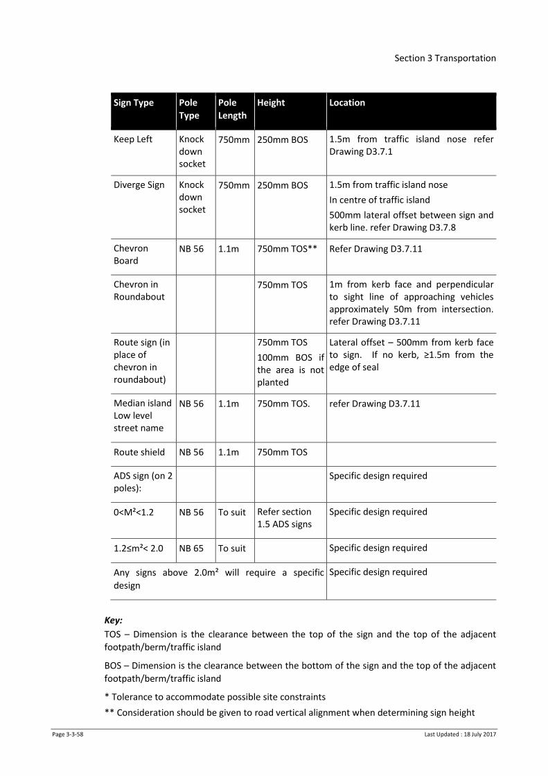
Section 3 Transportation
Page 3-3-58 Last Updated : 18 July 2017
Sign Type Pole
Type
Pole
Length
Height Location
Keep Left Knock down socket
750mm 250mm BOS 1.5m from traffic island nose refer Drawing D3.7.1
Diverge Sign Knock down socket
750mm 250mm BOS 1.5m from traffic island nose
In centre of traffic island
500mm lateral offset between sign and kerb line. refer Drawing D3.7.8
Chevron Board
NB 56 1.1m 750mm TOS** Refer Drawing D3.7.11
Chevron in Roundabout
750mm TOS
1m from kerb face and perpendicular to sight line of approaching vehicles approximately 50m from intersection. refer Drawing D3.7.11
Route sign (in place of chevron in roundabout)
750mm TOS
100mm BOS if the area is not planted
Lateral offset – 500mm from kerb face to sign. If no kerb, ≥1.5m from the edge of seal
Median island Low level street name
NB 56 1.1m 750mm TOS. refer Drawing D3.7.11
Route shield NB 56 1.1m 750mm TOS
ADS sign (on 2 poles):
Specific design required
0<M²<1.2 NB 56 To suit Refer section 1.5 ADS signs
Specific design required
1.2≤m²< 2.0 NB 65 To suit Specific design required
Any signs above 2.0m² will require a specific
design
Specific design required
Key:
TOS – Dimension is the clearance between the top of the sign and the top of the adjacent
footpath/berm/traffic island
BOS – Dimension is the clearance between the bottom of the sign and the top of the adjacent
footpath/berm/traffic island
* Tolerance to accommodate possible site constraints
** Consideration should be given to road vertical alignment when determining sign height

Section 3 Transportation
Page 3-3-59 Last Updated : 18 July 2017
3.3.11.4 Parking Signs
Parking signs shall be as detailed in Traffic Control Devices Manual.
3.3.11.5 Signs on Cycleways or Shared Walkway/Cycleways
Refer Drawing D3.7.5 for signage of shared cycle path start and end points.
3.3.11.6 Street Name Signs
Design
Street name signs shall be designed in accordance with the Traffic Control Devices Manual –
Part 2: Direction, service and general guide signs, and Table 3-9.
On no exit roads, a 75mm tall separate, supplement plate shall be attached (taped) to the
bottom edge of the street name sign.
All signs are to be double-sided, except those on medians or at the head of ‘T’ intersections.
Repeater plates of the primary road shall be erected at every intersection.
Legend
The standard abbreviations listed in Traffic Control Devices Manual – Part 2: Direction, service
and general guide signs shall be used, with the addition of the term ‘Rise’ (no abbreviation
necessary).
These abbreviations shall have a letter height of 50mm and 75mm for secondary and primary
streets respectively.
Location of Street Name Signs
Street name signs are to be located in accordance with Table 3-9 above. If there is a utility
pole in the proposed location, then the signs shall be attached to it. (See Note 4 of Drawing
D3.7.11).
Street name signs at signalised intersections shall be installed in accordance with Drawing
D3.12.6.
Poles shall be either NB56 or NB65 steel poles, as appropriate to the type of sign required.
3.3.11.7 General Interest Signs (formerly referred to as Amenity Signs)
Refer to section in Traffic Control Devices Manual – Part 2.
Design
General Interest signs are to be in accordance with the following specification:
Letter height 125mm
Letter styles as for Street Name signs
Letter spacing as for Street Name signs
Background depth 175mm
Blade profile 90° cuts at both ends
Colours Blue reflectorised lettering on a white reflectorized
background - all reflectorisation to be Engineering Grade

Section 3 Transportation
Page 3-3-60 Last Updated : 18 July 2017
Arrows Blue reflectorised triangular arrow at the end of sign plates.
Refer to D3.7.2, 3.7.3 and 3.7.4.
Location
General Interest signs are to be located in accordance with the following specification:
Height of sign blade As for Street Name signs
Lateral offset As for Street Name signs
Number of signs Maximum of two General Interest signs per facility
Note: In addition to standard mounting requirements (Dwgs D3.7.11 and D3.12.6), General
Interest signs are to be attached below existing street name signs.
3.3.11.8 Guide and Information Signs
Refer to Traffic Control Devices Manual – Part 2.
3.3.11.9 General
All signs shall be designed and constructed in accordance with Traffic Control Devices Manual,
and the following:
a) Signs shall be Class 1 wide observation angle (VIP or equivalent) reflective sheeting
b) Face of sign shall be rivetless
3.3.11.10 Attachment
Signs shall be attached to posts or overhead gantries using Signfix or equivalent brackets as
approved by Council. The Contractor shall be responsible for determining sign mounting
requirements.
3.3.11.11 Location
Signs shall have 0.5m offset from kerb or 1.5m from edge of seal.
Sign locations are to be confirmed on site by Council prior to installation.
Signs shall be angled for oncoming traffic in accordance with the sign reflective sheeting
manufacturer's specification.
3.3.11.12 Height
Signs located above carriageways shall have a minimum clearance of 5.0m.
Signs located in or above footpaths shall have 2.5m minimum clearance from the bottom of
the sign to the footpath.
Signs on grassed/planted areas shall have 2m minimum clearance to the bottom of the sign.
Direction signs located in roundabout splitter island shall be 50mm above ground level.
Section 3 Transportation
Page 3-3-61 Last Updated : 18 July 2017
3.3.11.13 Poles
Steel poles are to be either NB56 or NB65 poles appropriate to the type and size of sign
required and in accordance with Table 3-9. Poles are to be powder coated white. All poles are
to be capped with power coated top caps to match pole.
Timber poles shall be 100 x 100mm H4 dressed framing grade 1 or 2, pre-painted using one
undercoat and two topcoats of high gloss exterior white paint.
3.3.11.14 Installation details for posts and poles
Where installation and/or reinstatement work is required within a sealed surface, the surface
must be saw cut around the perimeter of the excavation. The replacement surfacing shall be of
a material and placed to match the existing surrounding surfacing.
3.3.12 Attachment of Signs to Poles
3.3.12.1 NB56 Steel Poles
All street name signs on NB56 powder coated steel poles shall be attached as detailed in
Drawing D3.7.11. All other signs shall be bolted to the pole with two 6mm dia. galvanised bolts
to the sign/sheeting manufacturer’s specification. Refer to Drawing D3.12.6 for signal pole
mounting specifications.
3.3.12.2 NB65 Steel Poles
All signs on NB65 powder coated steel poles shall be attached with two 10mm dia. galvanised
bolts to the sign/sheeting manufacturer’s specification. Refer to Drawing D3.12.6 for signal
pole mounting specifications.
3.3.12.3 School Patrol Signs
Support posts shall be white, Type II bollards which are to be embedded in a concrete base
(400mm x 400mm square x 500 deep) and set so that the top is 1.00m above ground level. The
sign support bracket shall be attached using 2 10mm dia. x 120mm long galvanised coach
bolts, and shall be manufactured and installed in accordance with Drawing D3.7.15.
3.3.12.4 Kea Crossing Flag and Pole
Kea Crossing flags and poles are to be constructed and installed in accordance with Drawings
D3.7.13, D3.7.14
3.3.12.5 Overhead Gantries
Overhead gantries shall be fabricated and installed in accordance with the standard Drawings
D3.7.18 and the following additional requirements:
a) The gantry design will depend on the proposed size of sign and hence loading and ground
clearance
b) Sign mounting uprights shall be spaced at no greater than 900mm centres
c) Overhead gantries may be constructed from either a single piece welded or a bolted
outreach arm
d) Gantries shall be hot dipped galvanised after fabrication. All mount bolts shall be
galvanised

Section 3 Transportation
Page 3-3-62 Last Updated : 18 July 2017
3.3.12.6 Edge Marker Posts
All edge marker posts (EMP) shall be constructed in accordance with the NZTA’s Specification
M/14 : Edge Marker Posts.
EMPs shall be located on rural roads only and in accordance with the MOTSAM – Part 2:
Markings.
3.3.12.7 Semi - Rigid Barriers (W-Section)
All barriers complete with reflective inserts are to be constructed in accordance with the
NZTA’s Specifications M/17P : W-Section Bridge Guardrail, P/15P : Fabrication and Assembly of
Standard Guardrails and Handrails for Highway Bridges and Bridge Approaches, M/23 : Road
Safety Barrier Systems, and with AS/NZS 3845.
Painting of barriers may also be required on a case-by-case basis and should be confirmed with
the relevant Council. All painting shall consist of at least two finish coats of water based
commercial grade paint (colour to be specified by Council). All dirt, grime and loose and flaky
paint shall be removed from the surface prior to painting. It may be necessary to undercoat in
some areas as required. All painting is to be carried out in accordance with the manufacturer’s
specifications. Reflective inserts are to be retained.
3.3.12.8 Timber Sight Rails
All painting of timber sight rails shall be completed with at least two finish coats of water
based commercial grade white paint. All dirt, grime and loose and flaky paint shall be removed
from the surface prior to painting. It may be necessary to undercoat in some areas. All painting
shall be carried out in accordance with the manufacturer’s specifications.
3.3.12.9 Themed Street Furniture (bins, seats, specialised street lighting, etc)
The Council may have towns or suburbs with a particular street furniture theme. For details of
these themes, refer to Appendices.
3.3.12.10 Wheel stops
All wheel stops shall be standard pre-cast rubber units, with the top of the wheel stop being no
more than 100mm above the adjacent surface.
3.3.12.11 Wayfinding Signage
Wayfinding signage is subject to additional specifications and requirements.
3.3.13 Pedestrian Barrier Rails and Handrails
Pedestrian barrier rails and handrails shall be constructed and installed in accordance with the
following Drawings:
D3.8.7 - CBD pedestrian barrier
D3.8.8 - Pedestrian balustrade barrier.
D3.8.9 - pedestrian barrier fence detail
D3.8.10 - pedestrian access way fence detail
D3.3.11 - pedestrian handrail or walkway barrier
3.3.14 Walkway Barriers and Cycle Racks
All walkway barriers and cycle racks shall be constructed and installed in accordance with
Drawings D3.8.2, D3.8.3 and D3.8.11 Bus Stops.

Section 3 Transportation
Page 3-3-63 Last Updated : 18 July 2017
This section covers the supply and installation of all components necessary for a bus stop
including signage, seats, raised accessible kerb lines and bus shelters.
3.3.14.1 Standards
All bus stops shall be constructed in accordance with the Auckland Regional Transport
Authority (ARTA) Bus Stop Infrastructure Design Guidelines2 unless Council has requirements
which will vary the above standard.
3.3.14.2 Signage
All signage shall be installed in accordance with the requirements set out in section 3.3.11:
Road Signage and Street Furniture. However some locations may require supplementary bus
stop signs. See Drawing D3.7.16.
3.3.14.3 Seats
Where seats are required, but there is no shelter, they shall be in accordance with Drawing
D3.8.14.
3.3.14.4 Accessible kerb lines and tactile paving
Where specified, accessible kerb lines and tactile paving shall be installed in accordance with
the ARTA Bus Stop guideline and Drawing D3.6.3 and D3.3.8.
3.3.14.5 Shelters
Bus shelters shall be installed as instructed by Council and in accordance with the following
Drawing D3.8.13 and D3.8.14.
The large size bus shelter shall be used in all locations except where an installed shelter would
narrow the adjacent footpath to less than 1.2m. The mini shelter shall be installed instead.
Bus shelters shall be painted/powder coated in black semi-gloss, except for the Orbiter bus
route which shall be Mambo Green and 2k silver or black.
3.4 Line Marking
This section covers all aspects of line marking, including the supply and fixing of reflective
and/or non-reflective road studs and delineators, and the removal of line marking.
3.4.1 Setting Out and Timing
The proposed line marking is to be set out in accordance with the accepted drawings, and any
location marking out provided by Council, with modifications as necessary to make the ‘lines’
pleasing to the eye.
Where there are inconsistencies between the line marking layout plans and the NZTA
specifications, the line marking layout plans shall prevail.
Council’s approval of the set out is required prior to marking. In order to achieve this with the
least delay, at least 48 hours’ notice prior to approval being required shall be given to Council.
Incorrect line marking that has been applied without approval of the set out shall be removed
at no cost to Council.
2 This is the default NZTA standard.
Section 3 Transportation
Page 3-3-64 Last Updated : 18 July 2017
On new surfaces, marking of centreline, limit lines and other intersection markings such as
Give Ways shall be completed within 48 hours of completion of the surfacing.
For roads that are not open to traffic, such as new subdivisions, these markings shall be
completed before the road is opened to the public.
Other markings on new surfaces shall be completed within seven days of surfacing. For other
works such as line removals or maintenance, timing will be specified by Council.
3.4.2 Paint Types
At a minimum, all paint shall at least conform to NZTA’s specifications M/7 ‘Class A’ type and
P/12.
All new line markings shall generally be waterborne/acrylic.
Chlorinated rubber or alkyd is to be used for arterial and collector roads on their final
surfacing.
Thermoplastics are to be used in CBD areas. Alkyd paint must be used on sites that are to be
re-marked with thermoplastic paint at a later date.
3.4.2.1 Waterborne/Acrylic Paint
Waterborne paint shall be applied in accordance with NZTA Specifications P/12 and M/7, with
the following amendments.
Clause 13.1 (a) NZTA P/12 – replace
with:
‘The finished dry film thickness shall be 300
microns or greater as defined by the equation
in NZTA P/12 ‘
All waterborne/acrylic markings are to be reflectorised in accordance with NZTA P/22.
3.4.2.2 Alkyd Paint
Alkyd paint shall be applied in accordance with NZTA Specifications P/12 and M/7, with the
following amendments.
Clause 13.1 (a) NZTA P/12 – replace
with:
‘The finished dry film thickness shall be 180
microns or greater as defined by the equation
in NZTA P/12’
3.4.2.3 Chlorinated Rubber
Chlorinated Rubber or similar paint shall be applied in accordance with NZTA Specifications
P/12 and NZTA M/7, with the following amendments.
Clause 13.1 (a) NZTA P/12 – replace
with:
‘The finished dry film thickness shall be 220
microns or greater as defined by the equation
NZTA P/12’
All chlorinated rubber markings are to be reflectorised in accordance with NZTA P/22.

Section 3 Transportation
Page 3-3-65 Last Updated : 18 July 2017
3.4.2.4 Thermoplastic
Where long life or thermoplastic materials are specified they shall be supplied and applied in
accordance with NZTA M/20 specification. The type of long-life material proposed to be used
and details of type of approval to NZTA M/20 specification shall be submitted with any tender
or proposal.
3.4.2.5 Re-markings
A re-mark will be required within 3-6 months (or prior to completion of defects period if
shorter) depending on wear and deterioration of the markings. This re-mark will be with the
final paint type specified in section 3.4.22 above. Approval must be obtained from Council
prior to completing this re-mark to determine the paint type and final layout of the line
marking.
3.4.3 Equipment Certificates and Staff Competence
All line marking equipment used for applying paint and glass beads shall have a current NZTA
T/8 certification and be in a certifiable state.
All line marking equipment used for applying long life or thermoplastic materials shall have a
current NZTA T/12 certification and be in a certifiable state.
The senior operator of each road marking crew must have at least a minimum qualification
approved by the Industry Training Organisation (ITO). At least one person in each road marking
crew shall be a qualified Traffic Controller (TC) in accordance with the NZTA COPTTM.
3.4.4 Raised Pavement Markers (RPM)
All reflectorised pavement markers are to be glass faced (long life) or equivalent with NZTA
Specification M/12 type approval.
All pavement markers are to comply with NZTA M/12 (and NZTA M/12 notes). Installation of
raised pavement markers shall comply with NZTA P/14, MOTSAM, and any subsequent NZTA
document (e.g. RTS 4 ‘Guidelines for Flush Medians’). Further to this, Council may require
specific RPM layouts in certain locations.
Where ‘Active’ RPMs are specified, these shall incorporate solar panels and LED lights so that
they do not rely solely on reflected light.
3.4.5 Removal of Line marking
When redundant line markings require erasure, Council will specify the method to be used.
3.4.5.1 Removal
When ‘removal’ is specified, the line marking material (paint or thermoplastic) shall be
removed from the road surface. Typical methods include grinding, sandblasting (wet or dry)
and ultrahigh-pressure water cutting, but other methods may be considered acceptable by
Council. Care shall be taken so that damage is not caused to the underlying road surface and
that ‘ghosting’ of the marking does not occur.
Once complete, the surrounding area shall be swept clean of all sand, paint chips or other
debris. This material shall be suitably disposed of with care being taken to ensure that no solid
matter enters any waterway or stormwater system as a result of the removal operation. This
may require the placement of filters or similar on catch pits and other drainage features.

Section 3 Transportation
Page 3-3-66 Last Updated : 18 July 2017
Details of methodology, including materials to be used, equipment, staff skills and
qualifications and quality assurance shall be supplied with tenders or proposals.
3.4.5.2 Cold Applied Plastic Blackout
Permanent erasure of markings may be specified to be carried out with cold applied plastic
(CAP) material.
Existing long life markings or multi-layered line markings should be ground off before applying
CAP Blackout. The base coat shall be a two-component cold plastic, designed and formulated
for use as a road marking material and complying with NZTA specification M/20. The CAP shall
be pigmented to a grey or charcoal colour that is close to the colour of the existing road
surface. The product shall be mixed and applied in accordance with manufacturer’s
instructions.
Where the area to be blacked out abuts markings that are to remain, the edge of the blackout
shall be masked off, otherwise an irregular edge to the blackout is desirable to minimise any
ghosting effect. While the plastic material is still wet, crushed stone or grit shall be evenly
broadcast onto the base.
The grit shall be a sound crushed mineral or synthetic aggregate with 95% passing a 6.7mm BS
sieve and no more than 15% passing a 2.36mm BS sieve. The CAP material thickness and grit
size shall be matched so that approximately 60% of the grit depth is embedded into the plastic
material.
The aggregate shall have a maximum of 2% weak materials when tested using the Australian
Weak Particles Test (AS 1141.32).
3.4.6 High Friction or Coloured Aggregate Surfacing
High friction or coloured aggregate surfacing is to be applied at locations specified by Council.
Both surfacing types generally use a specialised aggregate bonded to the road surface in an
epoxy or polyurethane resin so are included in the same specification.
Proprietary surfacing systems shall be applied in accordance with the manufacturer's
specification and by the manufacturer's approved applicators.
Documents that relate to this section are the NZTA Specification M/6 : Sealing Chip.
All technical documentation regarding the proprietary product or system to be used shall be
submitted.
3.4.6.1 Surface Preparation
The surface shall be clean of any dust, detritus or loose matter. Any oil visible on the surface
shall be removed by washing with a detergent solution, followed by flushing with clean water,
or other suitable system.
Care shall be taken to ensure that no solid matter enters any waterway or stormwater system
as a result of the removal operation. This may require the placement of filters or similar on
catch pits and other drainage features.
The surface is to be completely dry before application of the binder.
All existing line marking, pavement markers, catch pits and kerbing shall be suitably masked so
that only the road surfacing is coated.

Section 3 Transportation
Page 3-3-67 Last Updated : 18 July 2017
The suitability of application to the pavement at the sites specified shall be discussed with
Council using the manufacturer’s guidelines.
3.4.6.2 Binder
The binder shall be a suitable epoxy, polyurethane or other approved proprietary product
compound. When used in conjunction with coloured aggregates the binder shall be pigmented
to the same colour as the aggregate. Thermo plastic binders shall not be used.
The cured binder shall be flexible so that it does not crack or delaminate under traffic loadings
on non-rigid pavements.
The binder shall be capable of holding the aggregates so they do not become embedded or
dislodged under heavy braking.
3.4.6.3 High Friction Aggregate
The aggregate shall be calcined bauxite or equivalent, which has a PSV greater than 70 when
tested in accordance with BS 812-Part 114.
The grading of the aggregate shall be as follows.
a) less than 5% retained on 4.75mm BS sieve
b) less than 5% passing 1.18mm BS sieve
The aggregate shall be clean and free of foreign matter. The aggregate shall comply with the
NZTA specification M/6 strength, shape and weathering resistance requirements.
3.4.6.4 Coloured Aggregate
The aggregate shall be a chemically inert, semi translucent, synthetic aggregate that complies
with shape, strength and weathering requirements of the NZTA specification M/6 and is
coated with colouring compound(s) to produce the specified colour.
The grading of the aggregate shall be as follows.
a) less than 5% retained on 4.75mm BS sieve
b) less than 5% passing 1.18mm BS sieve
The aggregate and binder system shall be designed to achieve a high level of colour retention
and resistance to both traffic abrasion and weather such that colour is intact and effective for
at least five years from the initial installation. The aggregate shall have a minimum PSV value
of 50 when tested in accordance with BS 812-Part 114. The surfacing must be capable of being
cleaned by high pressure water jet to remove dirt, grime and debris in order to restore the
colour.
3.4.6.5 Mixing, Batching and Application
The manufacturer’s guidelines for the mixing, batching and application rates of product shall
be followed, unless otherwise directed by Council.
3.4.6.6 Curing and Aftercare
All masking shall be removed together with the binder adhering to it. During the curing period,
no disturbances or trafficking of the treated surface is permitted.
The cure time shall be to the manufacturer’s recommendations required under the particular
site conditions.
Section 3 Transportation
Page 3-3-68 Last Updated : 18 July 2017
Before trafficking, excess chip shall be removed. Along with any subsequent chip which may
have eroded off the treatment for a period of one month following opening of surface to
traffic.
3.4.6.7 Performance
The minimum performance requirements are:
a) SCRIM Value – shall be at least 0.7 ESC
b) Aggregate Retention – a visual assessment of the surfacing shall be performed to assess
the level of coverage and retention. Aggregate retention shall be assessed by determining
coverage on any 300mm x 300mm area. The surface shall be rejected if any three locations
have less than 95% chip coverage
c) Texture Depth – the surfacing shall be rejected if any three locations have a mean profile
depth of 1.0 mm or less (105mm sand circle if determined in accordance with NZTA
Specification T/3).
d) Cracking/Delamination/Sliding – the surfacing shall be rejected if there are any of the
above conditions present at the end of the three month defect liability period.
3.4.6.8 Cleaning
When cleaning of existing high friction or coloured surfacing is required, a high-pressure water
jet or other suitable means shall be used to remove all dirt, grime, debris and the like from the
surface. Care shall be taken to avoid damage to the surfacing.
Care shall be taken to ensure that no solid matter enters any waterway or stormwater system
as a result of the removal operation. This may require the placement of filters or similar on
catch pits and other drainage features.
3.4.7 Coloured Markings
When specified, some markings may be required in colours other than white or yellow.
Typical applications are.
a) Green for cycle way markings or bus only lanes
b) Blue for disabled car park spaces
Actual colours will be specified at the time. Such markings shall use the applicable paint type
specified in section 3.4.2, coloured to the specified colour. Paint application shall be in
accordance with the relevant clauses of this specification.
3.4.8 Temporary Markings
When specified, temporary markings may be required that can easily be removed when no
longer needed. Such markings shall be capable of withstanding normal road traffic and
weather conditions for a period of at least three months, or longer if specified. When no
longer required the markings shall be removed without causing damage to the underlying road
surface.
Full details of materials proposed for temporary markings, their method of application and
removal, and typical properties shall be supplied with any proposal for use. All materials shall
be handled and applied in strict accordance with manufacturer’s specifications and datasheets.
In particular, all environmental precautions shall be adhered to.
Section 3 Transportation
Page 3-3-69 Last Updated : 18 July 2017
Typical methods of temporary marking include ‘removable paint’ and self-adhesive road
marking tape.
3.4.9 Non Standard Markings
3.4.9.1 Cycle Symbols
The cycle symbol shall be set out in accordance with the NZTA Traffic Control Devices Manual,
but may be scaled to be 1200mm or 800mm high as directed by Council.
3.4.9.2 Cycleway 'End'
The word 'End' shall be painted at the end of cycle lanes along with a cycleway symbol, where
directed by Council. 'End' shall be 600mm high x 900mm long.
3.4.9.3 Cycleway Hold Bars
Cycleway hold bars are used at signalised intersections with advance cycle 'stop-boxes'. The
cycleway hold bars shall be 100mm wide with 200mm gap. Refer to Drawing D3.9.1 for more
details.
3.4.9.4 Cycleway Hook Turns
Cycleway hook turns are to be provided at signalised intersections where turning right is likely
to be considered a difficult manoeuvre for cyclists. Final cyclist provisions are to be confirmed
by Council.
3.4.9.5 Speed Cushions
The approach faces of speed cushions shall be painted with reflectorised white triangles to
facilitate visibility. The width of the triangles shall be such that there are at least three triangles
on each speed cushion and the depth shall cover the full depth of the tapered approach face of
the speed cushion.
3.4.9.6 Pedestrian Platforms
The faces of raised pedestrian crossing platforms and full width speed control devices shall be
marked with white reflectorised cross-hatching as dimensioned in Traffic Control Devices Rule
Diagram M4-2.
3.5 Street Lighting Construction
3.5.1 Installation
Each street light position is an Installation as defined in AS/NZS3000.
All construction work to be undertaken by competent/approved contractors and in accordance
with the Electricity Regulations 2010, AS/NZS3000 and the applicable Electrical Codes of
Practice. The most recent amendments must be used and approved by the network company.
All installations are subject to test and provision of ESC or CoC
3.5.2 Connection to network
All proposed street lighting connections must be approved by the relevant network company
prior to commencement of the project.
The steps to follow in pre- installation and installation stages are outlined below:

Section 3 Transportation
Page 3-3-70 Last Updated : 18 July 2017
Submit proposed design/ lighting plan to the network company for verification of
supply points
Submit Application for New connections detailing additional load required for new
streetlights
In order to liven new lighting installations the network company will require the following
documentation:
Approved Application for New Connection
CoC or ESC signed by authorized person
As builts in format approved by the network company
Confirmation of practical completion or 224c sign off.
All parties involved in the street lighting installation shall comply with the network company’s
design and connections standards and procedures.
3.5.3 Installation
All Columns are to be installed in accordance with the manufacturer’s specification, electrical
codes and health & safety acts.
The column position in developed areas shall be pegged in advance of the work and adjacent
property owners notified in writing of the works so that any issues over column location can be
resolved before installation begins.
Contractor to submit Corridor Access Request and confirm underground services location prior
to groundworks commencing in developed areas.
If the contractor finds underground bed rock (e.g. rhyolite) or finds underground services not
allowed for, that precludes installing a column in the desired location, they are to contact the
council for guidance rather than simply moving the column.
Any groundwork carried out for installation is to be re-instated to council’s standard.
Access doors shall be accessible.
Any damage caused prior to the hand-over to HCC must be repaired as new with all warranties
remaining intact.
Internal wiring, earthing and circuit protection devices to comply with the network company’s
Design and Construction Standard
Luminaires shall be installed on columns in accordance with the manufacturer’s
recommendations. The horizontal axis shall be level and with the specified tilt angle. Where
existing brackets or outreaches have a different tilt angle to that specified for new lights, new
luminaire with internal tilt mechanism may be used or suitable tilt wedges shall be installed so
that the existing luminaires have the same tilt angle as any new fittings.
3.5.4 Cables
Underground cable installations shall be provided to all street lighting columns except for
lights specified to be installed on existing power poles. Cable route and conductor sizes shall
be designed and installed in accordance with WEL Networks requirements. Warranty period
for new cables is 12 months.
All new installations shall be designed to be controlled through the Network Owner’s control
system.

Section 3 Transportation
Page 3-3-71 Last Updated : 18 July 2017
All column installations shall be provided with approved internal termination junction boxes
for terminating lighting circuits. These are to be located at the gear openings of each column.
Cables installed vertically on power poles shall be fitted and enclosed in accordance with
requirements of the network company.
3.5.5 Trenching
Underground cables to be installed to the network company’s requirements. In order to
prevent damage to road pavement and minimise disruption to the public thrusting must be
used under existing carriageways, vehicle entrances and footpaths
Location of the cables in green fields should be as detailed in Drawing D3.1.3 Location of
Services in Transport Corridor.
3.5.6 Lighting Upgrades
Where lighting columns or circuits are being relocated, extended or upgraded, the existing
supply, protective devices and switching control may be reused if it is in compliance with this
specification.
In the event that an existing circuit is extended, the network company will confirm if the
supply relays and fuses are suitably rated for the additional electrical load of the new lights.
The Contractor will be responsible for any costs associated with uprating the supply point,
fusing, changing relays or fitting contactor sets associated with the additional lighting load.
All additional fittings and materials used shall be new and consistent throughout the
installation. If in-fill lighting or continuation of an existing system the new fittings and
materials shall match the existing, if practicable.
3.5.7 Existing Luminaires, Columns and Control Gear Made Redundant
The Council’s Street Light Maintenance Contractor shall be given an opportunity to acquire any
surplus luminaires, columns and associated spare parts made redundant, for the purpose of
utilising them as maintenance spares. The Contractor shall be responsible for disposing of any
redundant ‘not wanted’ materials including capacitors containing PCB’s.
All non-usable parts are to be disposed of correctly and certificates provided to Council to this
effect.
3.5.8 Inspections and Testing
Prior to commissioning all inspections and testing required by the network company shall be
carried out. Written confirmation is required from the network company that it accepts all
underground cabling and circuitry and will assume responsibility for future maintenance and
renewal.
A lux survey may be requested by Council at the contractors cost.
3.6 Traffic Signals
3.6.1 Scope
This section covers the procedure and requirements for all new or upgraded traffic signals that
are to be managed by Hamilton City Council. This includes the design, supply, installation, and
commissioning of new and existing traffic signal equipment.

Section 3 Transportation
Page 3-3-72 Last Updated : 18 July 2017
3.6.2 Specifications
All traffic signals are to be installed in accordance with the Specifications and Standards listed
in Clause 3.1.2. The following Council specifications supersede NZTA P43 requirements.
Where reference is made in any Specification to RCA or Client, this shall be read as Council.
3.6.3 Traffic Signal Equipment
3.6.3.1 General
This section contains specific requirements for the supply and installation of the controller,
detectors, junction boxes and poles.
3.6.3.2 Traffic signal controller
Unless specified, the coating colour shall the industry standard to match existing controllers in
Hamilton.
A sticker shall be placed on each controller box in accordance with the following figure.
Figure 3-1: Traffic Signal Box Sign
3.6.3.3 Detector Loop Encapsulation
The approved flexible sealant as referred to in P43 is Plasticast LQB Tixophiate, which is a two
part epoxy compound formulated specifically for the encapsulating of traffic signal detector
cable loops which are embedded in asphaltic road surfaces.
3.6.3.4 Kerbside Junction Boxes
Access for loop-feeder between detector loop and toby box may be obtained in two ways:
1) Under kerb access - to be used in all cases where new kerb and channel is to be constructed;
Under kerb access shall consist of 25mm alkathene water pipe laid from the toby box under
the kerb and to within 50mm of the top of the seal and within 100mm of the edge of the
seal. The access hole in the pavement shall be backfilled, compacted with basecourse
material, and sealed.
Faults Faults phone phone 07 838-669907 838-6699 and quote:and quote:
4 0 5 84 0 5 8
out of hamilton within hamilton

Section 3 Transportation
Page 3-3-73 Last Updated : 18 July 2017
2) Saw cut through kerb and channel - may be used where existing kerb is to be retained;
A 5mm wide saw-cut may be made through the kerb and channel and sealed with Sikadur 43
epoxy resin mortar* or equivalent
3.6.3.5 Shop Verandas, Poles and Other Obstructions
Any obstructions which will interfere with the installation, visibility or operation of the signals
will be removed or altered by the Contractor.
Where such obstacles originate in private property, clearance to proceed with this work shall
first be obtained from Council. Some delay may occur while the property owner is contacted.
Note: All alterations to services will be undertaken by the appropriate service authority.
3.6.4 Communications
Unless otherwise specified, all new traffic signals and cameras shall be connected to the HCC
City Transportation Unit’s (CTU) traffic signal network. This network uses a combination of 4G
wireless, fibre and point-to-point links. Either one of these methods may be appropriate for
the site. Council will advise the appropriate communication method for the site and in most
cases will provide pre-configured hardware for the Contractor to install, such as a router and
radio.
A radio must be mounted appropriately (typically attached to a signal pole) to achieve the
signal strength requirements. The router shall be housed in the traffic signal controller cabinet.
Each installation must include initial site coverage testing and scoping, power supply to the
radio, and all associated ducting and cables including a shielded outdoor grade cat6 cable from
the controller to the radio running inside the pole to the radio mounting location.
The traffic signal controller must achieve continuous SCATS communications for a minimum of
48 hours prior to commissioning.
3.6.5 Provision of Cameras
Unless otherwise specified by Council a traffic monitoring camera must be installed and
connected at all new traffic signal installations or sites subject to major upgrade, with the
exception of mid-block pedestrian crossings. All camera hardware must have a minimum
warranty period of 12 months from the date of installation.
3.6.5.1 Camera Specifications
Traffic monitoring camera must meet the following technical requirements:
a) Cameras are to be digital, IP based, PTZ, outdoor units
b) Each new installation shall include the camera and PTZ unit, controller and
communications interface, power feed, housing, mounting, and pole (if required)
c) Cameras must be compatible with the Milestone and DVTel management systems
d) Unless specified, the required camera viewing distance shall be assumed to be 250m
e) Minimum 12x optical zoom
f) The zoom and stability shall be such that the displayed image at the viewing distance with
maximum optical zoom is no larger than the road carriageway, and image shake does not
exceed 3% of the image size in any direction

Section 3 Transportation
Page 3-3-74 Last Updated : 18 July 2017
g) Image sensor must be colour CCD with minimum size ¼’
h) Minimum horizontal resolution of 480 lines
i) Appropriate sensitivity and image correction for day and night observations
j) 360 degree pan rotation with image auto-flip, allowing tilt from horizontal to -90 degrees
k) Minimum of 10 pre-set PTZ positions
l) Camera and housing to provide a minimum IP66 ingress protection to IEC 60529, and
include a sun shield and condensation prevention
m) Appropriate video compression to communicate over the communications network (H264
is the preferred method)
3.6.5.2 Camera Location and Mounting
The camera should be located such that:
a) Every traffic lane is visible at the intersection limit line
b) Required viewing distance is achieved down each leg
c) Viewing is optimised for legs with adjacent signalised intersections
Unless otherwise specified, mounting on a traffic signal pole such as a Joint Use Mast Arm
(JUMA) is permitted where practical.
The Contractor shall supply and install a shielded outdoor grade cat6 cable from the controller
to the camera location, running inside the pole to the camera mounting location.
Council must approve the final location prior to installation of pole or camera. A site
assessment plan showing the location and visibility of the proposed camera must be provided
to Council for approval.
3.6.6 Warrantees, Guarantees and Maintenance
All materials and equipment supplied and/or installed (including the installation) shall have
guarantees and warrantees in accordance with P43.
Practical completion will not be issued until Hamilton City Council and the current signals
maintenance contractor have approved the works and site operation. Hamilton City Council’s
Signal Maintenance Contractor will carry out regular maintenance on the intersection
immediately following practical completion and if any faulty equipment or installation work is
identified, then the Contractor responsible for installing the equipment will be required to fix
and/or supply parts to fix the fault at no cost to the Road Controlling Authority.
During the construction and maintenance periods, the Contractor shall also be required to pay
all costs incurred by Hamilton City Council’s Signal Maintenance Contractor (who has been
contracted to maintain the overall intersection) for isolating and making safe any reported
faults which can be directly attributed to the signal installation or modification work. This
includes any faults in materials, equipment or workmanship. The Contractor will be invoiced
separately for this work or more commonly, the amount will be deducted from the contract
price or from any maintenance retentions owing.
At the end of the maintenance/defects liability period the equipment shall be handed over in
full working order with no defects. Where such defects exist, whether in control equipment,
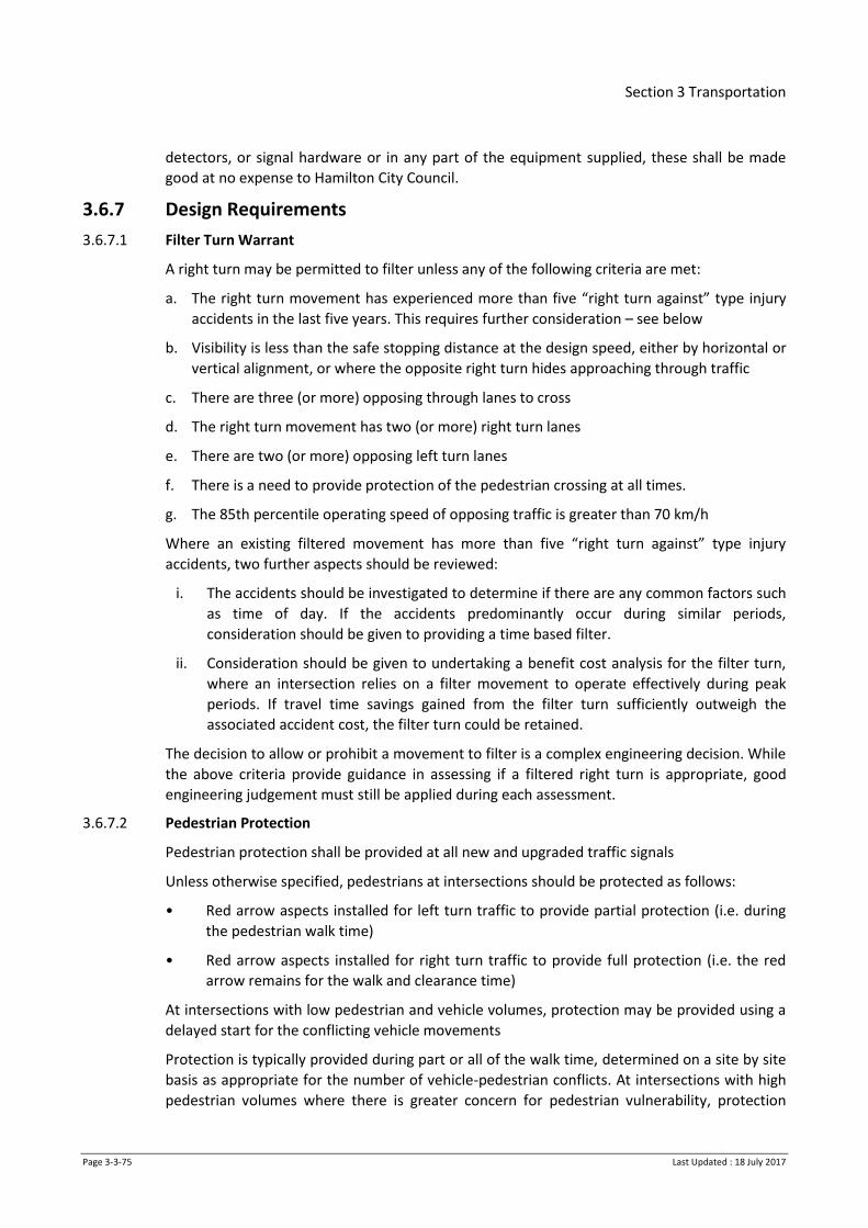
Section 3 Transportation
Page 3-3-75 Last Updated : 18 July 2017
detectors, or signal hardware or in any part of the equipment supplied, these shall be made
good at no expense to Hamilton City Council.
3.6.7 Design Requirements
3.6.7.1 Filter Turn Warrant
A right turn may be permitted to filter unless any of the following criteria are met:
a. The right turn movement has experienced more than five “right turn against” type injury
accidents in the last five years. This requires further consideration – see below
b. Visibility is less than the safe stopping distance at the design speed, either by horizontal or
vertical alignment, or where the opposite right turn hides approaching through traffic
c. There are three (or more) opposing through lanes to cross
d. The right turn movement has two (or more) right turn lanes
e. There are two (or more) opposing left turn lanes
f. There is a need to provide protection of the pedestrian crossing at all times.
g. The 85th percentile operating speed of opposing traffic is greater than 70 km/h
Where an existing filtered movement has more than five “right turn against” type injury
accidents, two further aspects should be reviewed:
i. The accidents should be investigated to determine if there are any common factors such
as time of day. If the accidents predominantly occur during similar periods,
consideration should be given to providing a time based filter.
ii. Consideration should be given to undertaking a benefit cost analysis for the filter turn,
where an intersection relies on a filter movement to operate effectively during peak
periods. If travel time savings gained from the filter turn sufficiently outweigh the
associated accident cost, the filter turn could be retained.
The decision to allow or prohibit a movement to filter is a complex engineering decision. While
the above criteria provide guidance in assessing if a filtered right turn is appropriate, good
engineering judgement must still be applied during each assessment.
3.6.7.2 Pedestrian Protection
Pedestrian protection shall be provided at all new and upgraded traffic signals
Unless otherwise specified, pedestrians at intersections should be protected as follows:
• Red arrow aspects installed for left turn traffic to provide partial protection (i.e. during
the pedestrian walk time)
• Red arrow aspects installed for right turn traffic to provide full protection (i.e. the red
arrow remains for the walk and clearance time)
At intersections with low pedestrian and vehicle volumes, protection may be provided using a
delayed start for the conflicting vehicle movements
Protection is typically provided during part or all of the walk time, determined on a site by site
basis as appropriate for the number of vehicle-pedestrian conflicts. At intersections with high
pedestrian volumes where there is greater concern for pedestrian vulnerability, protection

Section 3 Transportation
Page 3-3-76 Last Updated : 18 July 2017
should be provided for the walk time and some or all of the clearance time for conflicting
vehicles.
Full pedestrian protection should be considered at sites where an unusual layout causes
vehicles to interact dangerously with pedestrians, and consideration needs to be given to
conflicting movements to ensure capacity is not overly compromised.
Where a priority pedestrian crossing has no conflicting vehicle movements and is adjacent to a
main vehicle movement, the pedestrian phase should allow late introduction of the pedestrian
phase if sufficient time is available to complete the crossing within the associated vehicle
phase.
3.6.7.3 Advanced vehicle detectors
Advanced detectors can be costly to install and maintain but typically provide efficiency and
safety benefits. The suitability, number of detectors and their location shall be assessed on a
site by site basis.
At new intersections, advanced detectors should generally be provided on arterial roads and
any road with a posted speed limit above 50 km/h.
3.6.7.4 Network Operating Plan
The Hamilton Network Operating Plan covers day to day operation of the network in a way
that seeks to optimise the existing infrastructure and reflects the strategic priorities that have
been assigned to each of the user modes by location and time of day.
Any new or modified traffic signal site shall be assessed against the strategic intentions
discussed in the Network Operating Plan to ensure that they will reflect the defined road user
hierarchy and priorities.
3.6.8 Traffic Signal Procedure
The procedure set out in the table below applies to all Traffic signals that are to be managed
by CTU, including traffic signals that are installed on other RCA networks such as the local State
Highway network, Waipa District Council and Waikato District Council.
The table provides an overview of the entire process including the approvals and deliverables
required to enable the traffic signals to be managed by CTU.
Table 3-10: Procedures: Signal Plans, Software and Commissioning
Task Supply Description / Requirements Created By Approved by
Brief Design brief Design brief given to the signals consultant describing the traffic signal and civil works required
Client Signals Consultant
Justification Justification Report
Report justifying the need for traffic signal control
Signals consultant
Client
Design Report, plan and traffic modelling
Design plans and design report in accordance with relevant standards.
Level of service and 95%ile
Signals consultant
Client and City Transportation
Section 3 Transportation
Page 3-3-77 Last Updated : 18 July 2017
Task Supply Description / Requirements Created By Approved by
queue lengths for morning and evening peaks
A site plan with the preliminary design superimposed showing:
- Posts, lanterns, Street lighting
- Detectors
- Controller
- Road marking, signage and cycle facilities
- Phasing diagram and cabling diagram
- 5 Year CAS data
Peer review Review report Peer review audit by external competent traffic signal designer, of design plan and design report
Reviewer to supply letter of approval/memorandum with plan number once any amendments have been discussed and noted
External design reviewer
Signals consultant
and City Transportation
Final design Drawings and estimate
Final design plans including cable diagrams and phasing
Schedule of quantities including cable charts
Cost estimate
Final design report
Pre-construction Safety Audit covering Traffic Signals
Signals consultant
Client
Copy of Plans and Safety audit to City Transportation HCC for approval
Tender Tender documents, schedule, equipment and installation specification
City Transportation to check technical documents.
Appropriate references to the HCC ITS.
Controller Controller Information
Controller Information Sheets (CIS) includes:
Signals consultant or
City Transportation

Section 3 Transportation
Page 3-3-78 Last Updated : 18 July 2017
Task Supply Description / Requirements Created By Approved by
Sheets (CIS) - Controller type
- Lane layout
- Detectors
- Phasing
- Signal group numbering
- Timing details both vehicle and pedestrian
- Pedestrian crossing distances
- Flexilink details
- Special facility requirements
council approved signal consultant
for review
Controller Controller software
Controller Software including independent WinTraff test of PROM
Bench testing of software must be carried out by the contractor prior to commissioning and completed bench form supplied (refer P43)
Signals consultant or City Transportation nominated consultant
Contractor for bench testing
City Transportation
Supervision Supervision Construction supervision / MSQA
Client or nominated rep
Connections Connection for communications, cameras and power
Communications: See Clause 3.6.4.
The traffic signal controller must achieve continuous SCATS communications for a minimum of 48 hours prior to commissioning.
Power: For sites within Hamilton a Wel networks connection form (www.wel.co.nz) must be filled in and a sent to [email protected] (Contact energy) at least six weeks prior to commissioning. A copy must also be sent to the
Signals Contractor
City Transportation

Section 3 Transportation
Page 3-3-79 Last Updated : 18 July 2017
Task Supply Description / Requirements Created By Approved by
energy manager at Hamilton City Council for creation of new accounts. WEL Networks will provide an ICP and physical connection and return to Contact for the completion of the new connection
SCATS System set up and testing
SCATS graphics, related data and linking setup in accordance with HCC Traffic Signals Operational Standards Document
City Transportation
City Transportation
Pre commission checks
Completed site acceptance test (SAT)
Signals contractor shall complete the SAT (refer P43) in the presence of the RCA traffic signal representative (City Transportation)
Signals contractor
City Transportation
Commissioning Authorisation to switch on the traffic signals
Handover of new/upgraded signals to City Transportation to operate and manage.
Signed SAT and written approval to switch on the traffic signals by the RCA traffic signals representative (City Transportation)
Unless specific approval is given, commissioning shall not take place on a Friday or the day before a public holiday.
City Transportation and Contractor
City Transportation
Asset information
Asbuilts and associated documentation
Contractor to supply all required asset information as stated in P43, including:
- Final plans showing ducting and layout
- RAMM Asset Collection Sheet
- C&I sheet
- Keys
- Test certificates
Signals contractor
Client and City Transportation

Section 3 Transportation
Page 3-3-80 Last Updated : 18 July 2017
Task Supply Description / Requirements Created By Approved by
- Producer statements
- Cable termination chart
Safety Audit Post construction Safety Audit
A post conduction safety audit will be required at all new sites and upgraded signals that are complex or within high speed areas.
Client may request a post construction safety audits following any traffic signal upgrades or modifications at their discretion.
Qualified safety auditor
Client/City Transportation
3.7 Quality Systems
This section is intended to describe the formal testing and acceptance requirements of
construction. The design portion of this document must be read and complied with fully.
3.7.1 Inspections and Acceptance
This section details the inspections and hold points where council acceptance is required
before continuing. Site visits may be carried out at any time during construction. Specific
details about testing measures are detailed in section 3.7.2.
3.7.1.1 Carriageway Construction Inspections and Acceptance
After ‘Subgrade Testing Prior to Design’ (Clause 3.7.2.2) has been completed and a proposed
pavement design submitted, Council will review the investigation results and pavement design.
Once the subgrade has been shaped according to the design, review of subgrade testing in
accordance with Clause 3.7.2.2 shall be carried out.
Once sub-base has been constructed, review of sub-base testing according to section shall be
carried out.
Once basecourse has been constructed, review of basecourse testing in accordance with
clause 3.7.2.2 shall be carried out.
3.7.1.2 Kerb and Channel Inspections and Acceptance (hold point)
3.7.1.3 Footpath and Cycleway Inspections and Acceptance (hold point)
3.7.1.4 Signs and other street furniture Inspections and Acceptance (hold point)
3.7.1.5 Street Lighting Inspections and Acceptance (hold point)
The Installation contractor shall provide the following documentation to Council:
1. Approved Application for New Connection
2. CoC or ESC signed by authorized person
3. As built drawings in format approved by the electrical network provider including results
of inspections and testing.

Section 3 Transportation
Page 3-3-81 Last Updated : 18 July 2017
4. Street light control point form.
5. Lighting pole and luminaire data using RAMM Streetlight Data Form F3.10.
6. Network company’s approval sheet
7. Certificate of Compliance
8. Manufacturer Warranty Documents for Lights, Columns and Coatings.
The developer/contractor is responsible for any costs to remedy any deficient aspects of the
installation identified This includes any problems, failures or defects that may arise during the
stipulated defects liability period for the subdivision, or the guarantee period for individual
fittings or fixtures, whichever is greater
3.7.1.6 Traffic Signals
Traffic signals have a specific procedure set out in 3.6.8.
3.7.2 Testing Guidelines
The following are a summary of the testing requirements. The results of each of these tests
must be provided to Council.
3.7.2.1 Carriageway Test Spacing
Compaction and material strength tests are to be taken at the following locations and frequency:
Table 3-11: Test Spacing locations and frequency
For carriageways 4.0m
wide and less
Along centreline 15m spacing between tests
For carriageways
between 4.0m and 8.0m
At the kerbside wheel
tracks
Alternating Sides, 10 centreline metres
between tests
(20m repetition of testing rows)
For carriageways 8.0m
and wider
At centreline and
kerbside wheel tracks
Staggered across road, 10 centreline
metres between tests
(30m repetition of testing rows)
On small sites there must be a minimum of 10 tests carried out.
The kerbside wheel tracks are assumed to be 1m inside the kerb and channel alignment.
3.7.2.2 Subgrade Testing Prior to Design
Subgrade testing should begin at 100mm above the design subgrade level.
Subgrade testing is to be by Scala Penetrometer for all materials that are suitable.
If the material has larger aggregates then a Clegg Hammer test should be used instead.
3.7.2.3 Subgrade Testing Prior to Sub-base Construction
If subgrade improvement measures have been carried out (such as replacement with Pit Sand,
Granular Rock Fill Material, or use of a stabilisation agent) Pit Sand or stabilised materials shall
be tested by Scala Penetrometer. Granular rock shall be tested by Clegg Hammer.
The shape of the subgrade shall be measured by stringing.
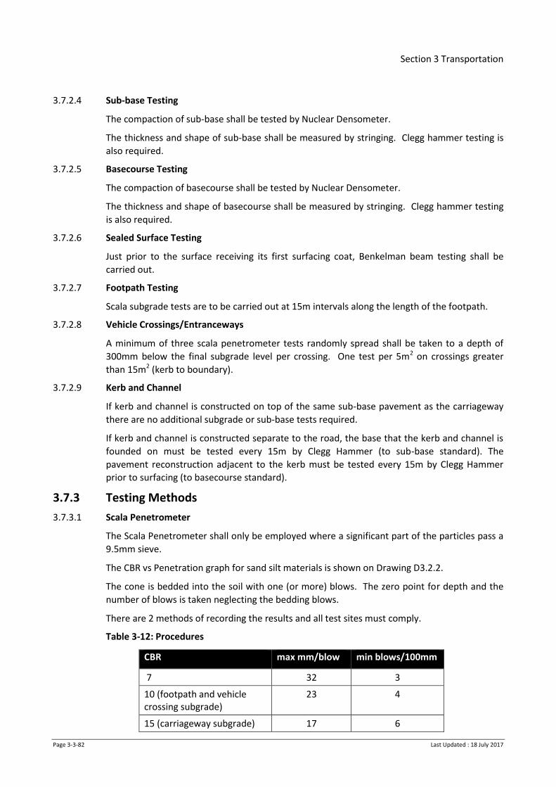
Section 3 Transportation
Page 3-3-82 Last Updated : 18 July 2017
3.7.2.4 Sub-base Testing
The compaction of sub-base shall be tested by Nuclear Densometer.
The thickness and shape of sub-base shall be measured by stringing. Clegg hammer testing is
also required.
3.7.2.5 Basecourse Testing
The compaction of basecourse shall be tested by Nuclear Densometer.
The thickness and shape of basecourse shall be measured by stringing. Clegg hammer testing
is also required.
3.7.2.6 Sealed Surface Testing
Just prior to the surface receiving its first surfacing coat, Benkelman beam testing shall be
carried out.
3.7.2.7 Footpath Testing
Scala subgrade tests are to be carried out at 15m intervals along the length of the footpath.
3.7.2.8 Vehicle Crossings/Entranceways
A minimum of three scala penetrometer tests randomly spread shall be taken to a depth of
300mm below the final subgrade level per crossing. One test per 5m2 on crossings greater
than 15m2 (kerb to boundary).
3.7.2.9 Kerb and Channel
If kerb and channel is constructed on top of the same sub-base pavement as the carriageway
there are no additional subgrade or sub-base tests required.
If kerb and channel is constructed separate to the road, the base that the kerb and channel is
founded on must be tested every 15m by Clegg Hammer (to sub-base standard). The
pavement reconstruction adjacent to the kerb must be tested every 15m by Clegg Hammer
prior to surfacing (to basecourse standard).
3.7.3 Testing Methods
3.7.3.1 Scala Penetrometer
The Scala Penetrometer shall only be employed where a significant part of the particles pass a
9.5mm sieve.
The CBR vs Penetration graph for sand silt materials is shown on Drawing D3.2.2.
The cone is bedded into the soil with one (or more) blows. The zero point for depth and the
number of blows is taken neglecting the bedding blows.
There are 2 methods of recording the results and all test sites must comply.
Table 3-12: Procedures
CBR max mm/blow min blows/100mm
7 32 3
10 (footpath and vehicle crossing subgrade)
23 4
15 (carriageway subgrade) 17 6

Section 3 Transportation
Page 3-3-83 Last Updated : 18 July 2017
As a means of compliance for an acceptable CBR in carriageways at the insitu subgrade, the
scala readings are averaged for the top 600mm. At the imported subgrade or lower subbase
surface, the scala readings are averaged for the full depth of the pavement layer being tested.
For footpath and vehicle crossing subgrade testing, the results are the average of the top
300mm.
3.7.3.2 Lab Tested Soaked CBR
Subgrade samples from the site are to be tested by an IANZ accredited laboratory for their
Soaked CBR (California Bearing Ratio).
3.7.3.3 Clegg Hammer
Where the Clegg Hammer is used, it shall be the Standard Australian Digital model with a 4.5
kg compaction hammer, using a drop height of 450 mm. The test certificate must be less than
12 months old.
Testing is carried out on a surface that has no loose material (removed by scuffing with a stiff
hand broom). The maximum Clegg Impact Value (CIV) at the end of the 4th blow shall be
recorded and the on-site CBR value shall be taken as 0.07 (CIV)2.
Table 3-13: Quality Systems Testing – Clegg Hammer Compliance Values
Compliance Values Clegg Impact Value (CIV)
Aggregate Subgrade (e.g. Granular rock fill material)
15
Subbase (trench reinstatement only) 25
Basecourse (trench reinstatement only) 40
3.7.3.4 Nuclear Densometer
Compaction testing should be done by a calibrated Nuclear Densometer in Backscatter
Transmission mode. The compaction is measured as a percentage of the Maximum Dry Density
of the material.
The test spacings for nuclear densometer may be double the standard carriageway test
spacings shown in Clause 3.7.2.1 with a minimum of 5 tests per site.
Table 3-14: Quality Systems Testing – Nuclear Densometer Compliance Values
Compliance Values Minimum Value Average (mean) Value
Subbase 92% MDD 95% MDD
Basecourse 95% MDD 98% MDD

Section 3 Transportation
Page 3-3-84 Last Updated : 18 July 2017
3.7.3.5 Benkelman Beam Test
The surface shall be tested prior to sealing with a standard Benkelman Beam test apparatus.
The organisation carrying out the tests shall have an IANZ accreditation.
The beam test shall be undertaken in accordance with NZTA’s specification T/1 : Benkelman
Beam Deflection Measurement except that the recordings for bowl deflection shall not be
recorded or used in the deflection calculation.
Deflections conform to the target figures in Table 3-15 below. No more than 10% of the test
results shall exceed the 90th Percentile and no single result shall exceed the maximum.
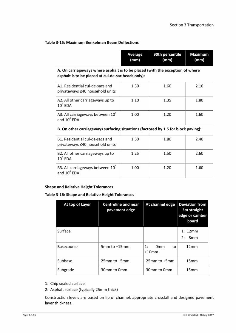
Section 3 Transportation
Page 3-3-85 Last Updated : 18 July 2017
Table 3-15: Maximum Benkelman Beam Deflections
Average
(mm)
90th percentile
(mm)
Maximum
(mm)
A. On carriageways where asphalt is to be placed (with the exception of where
asphalt is to be placed at cul-de-sac heads only):
A1. Residential cul-de-sacs and privateways ≤40 household units
1.30 1.60 2.10
A2. All other carriageways up to 105 EDA
1.10 1.35 1.80
A3. All carriageways between 105 and 106 EDA
1.00 1.20 1.60
B. On other carriageways surfacing situations (factored by 1.5 for block paving):
B1. Residential cul-de-sacs and privateways ≤40 household units
1.50 1.80 2.40
B2. All other carriageways up to 105 EDA
1.25 1.50 2.60
B3. All carriageways between 105 and 106 EDA
1.00 1.20 1.60
Shape and Relative Height Tolerances
Table 3-16: Shape and Relative Height Tolerances
At top of Layer Centreline and near
pavement edge
At channel edge Deviation from
3m straight
edge or camber
board
Surface 1: 12mm
2: 8mm
Basecourse -5mm to +15mm 1: 0mm to +10mm
12mm
Subbase -25mm to +5mm -25mm to +5mm 15mm
Subgrade -30mm to 0mm -30mm to 0mm 15mm
1: Chip sealed surface
2: Asphalt surface (typically 25mm thick)
Construction levels are based on lip of channel, appropriate crossfall and designed pavement
layer thickness.

Section 3 Transportation
Page 3-3-86 Last Updated : 18 July 2017
3.7.3.6 NAASRA Roughness
A post sealing NAASRA roughness measure is required. This measure shall be 70 maximum
average value with no more than 3% readings in excess of 70 for each traffic lane. The
Engineer will not consider remedial measures other than remaking of the pavement surface
for NAASRA roughness compliance. The survey result is required to be provided prior to the
issue of a practical completion certificate or 224C.
Roughness Specification
All road roughness surveys shall be in accordance with the latest revision of the “RAMM
Computer User’s Manual”, “RU Technical Recommendation TR12 Roughness Meter
Guidelines” and “Standard Operating Instructions for the NAASRA Roughness Meter” or the
RIMS “Specification for Road Condition Data Collection”. All results are to be reported as
NAASRA counts.
The Project Manager and test operators shall be suitably experienced and familiar with the
test equipment and results required.
Measurements are to be taken on the various road types as follows:
• On narrow single carriageway roads measurements are to be taken in the normal driven
wheel path. This is likely to straddle the road centre-line. The survey is to be completed
in one direction only. Data processing techniques should account for instances when the
vehicle deviates from the road onto the shoulder.
• On single carriageway, two-lane roads both increasing and decreasing lanes are to be
measured. The measurements are to be taken in the wheel paths. Where no obvious
wheel path is visible the measurements are to be taken 50 to 70 cm from the edge of
the pavement.
• On divided carriageway roads and service lanes survey both increasing and decreasing
lanes (both carriageways and service lanes). The measurements are to be taken in the
wheel paths; where no obvious wheel path is visible the measurements are to be taken
50 to 70 cm from the edge of the pavement.
• On dual carriageway roads survey both increasing and decreasing lanes (both
carriageways). The measurements are to be taken in the most heavily trafficked wheel
paths; where no obvious wheel path is visible the measurements are to be taken 50 to
70 cm from the edge of the pavement.
Laser Profilometer
The Consultant may use a non-contact laser profilometer to measure the paved roads'
longitudinal profile. The profilometer should conform to the ASTM E950-94 standard, have a
vertical resolution of less than 0.1 mm, and achieve a roughness measurement accuracy of<
0.1 mm. The Consultant shall record and report the longitudinal profile data and process the
profile data to provide and report NAASRA count/km. The lane roughness calculations are
made from the average of the left and right wheel path profiles, and the data recorded and
reported as follows:
• Number of wheel paths: two
• Longitudinal profile sampling interval: no more than 25 mm
• NAASRA Counts interval 20 m and 100 m.

Section 3 Transportation
Page 3-3-87 Last Updated : 18 July 2017
Any factors which may influence the survey result must be recorded during the survey and the
data corrected accordingly. These factors include, for example, survey speed in congested
areas, traffic congestion, sudden braking, and other events.
Some operational practices, such as sudden acceleration or braking during surveys, may also
influence the result and operators should avoid these.
Response Type Roughness Meter
The roughness data may be collected using a single/dual response-type roughness meter/s or
similar, with the instrument calibrated in accordance with ASTM E 1448-92/98. The roughness
data must be reported at 20 m and 100m intervals in NAASRA count/km. The vehicle speed
shall be recorded during the survey and taken into account when calculating the roughness
from the raw data.
Factors which may influence data quality must be recorded during the survey and the data
corrected accordingly. These include, for example, traffic congestion, pavement construction
activities and having to travel off the carriageway.
Equipment Validation
Roughness measurement equipment with current NZTA approval for use on the State Highway
network may be used without further validation checks. Other equipment must be validated
before use as described in the RIMS High Speed Data Collection Guidelines.
3.7.4 As-built Data Provision
As built data requirements are detailed in Section 1, Table 1-9.
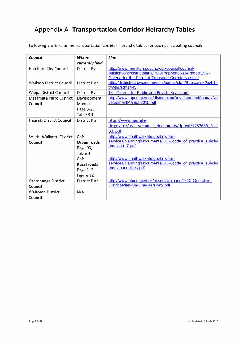
Page 3-3-88 Last Updated : 18 July 2017
Appendix A Transportation Corridor Heirarchy Tables
Following are links to the transportation corridor hierarchy tables for each participating council:
Council Where currently held
Link
Hamilton City Council District Plan http://www.hamilton.govt.nz/our-council/council-publications/districtplans/PODP/appendix15/Pages/15-7-Criteria-for-the-Form-of-Transport-Corridors.aspx#
Waikato District Council District Plan http://districtplan.waidc.govt.nz/pages/plan/Book.aspx?exhibit=ws&hid=1445
Waipa District Council District Plan T4 - Criteria for Public and Private Roads.pdf
Matamata Piako District Council
Development Manual, Page 3-2, Table 3.1
http://www.mpdc.govt.nz/districtplan/DevelopmentManual/DevelopmentManual2015.pdf
Hauraki District Council District Plan http://www.hauraki-dc.govt.nz/assets/council_documents/dptext/1252639_Sect8.6.pdf
South Waikato District Council
CoP Urban roads Page 93, Table 4
http://www.southwaikato.govt.nz/our-services/planning/Documents/COP/code_of_practice_subdivions_part_7.pdf
CoP Rural roads Page 112, Figure 12
http://www.southwaikato.govt.nz/our-services/planning/Documents/COP/code_of_practice_subdivions_appendices.pdf
Otorohanga District Council
District Plan http://www.otodc.govt.nz/assets/Uploads/ODC-Operative-District-Plan-On-Line-Version2.pdf
Waitomo District Council
N/A
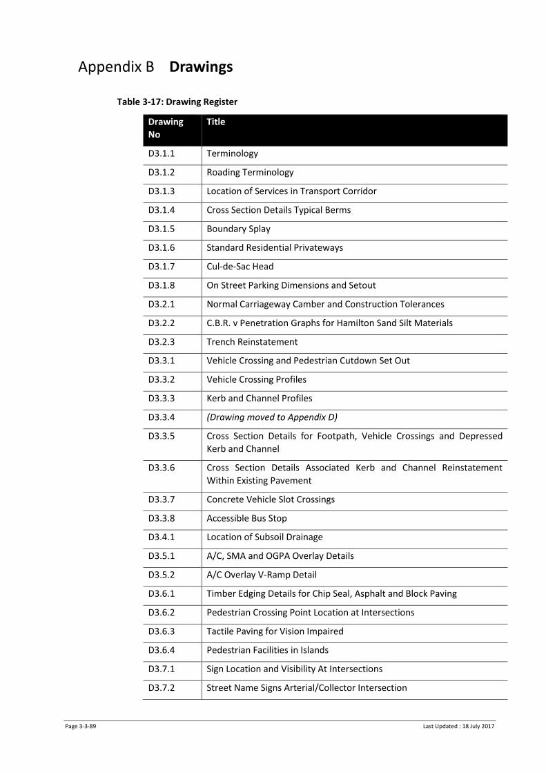
Page 3-3-89 Last Updated : 18 July 2017
Appendix B Drawings
Table 3-17: Drawing Register
Drawing
No
Title
D3.1.1 Terminology
D3.1.2 Roading Terminology
D3.1.3 Location of Services in Transport Corridor
D3.1.4 Cross Section Details Typical Berms
D3.1.5 Boundary Splay
D3.1.6 Standard Residential Privateways
D3.1.7 Cul-de-Sac Head
D3.1.8 On Street Parking Dimensions and Setout
D3.2.1 Normal Carriageway Camber and Construction Tolerances
D3.2.2 C.B.R. v Penetration Graphs for Hamilton Sand Silt Materials
D3.2.3 Trench Reinstatement
D3.3.1 Vehicle Crossing and Pedestrian Cutdown Set Out
D3.3.2 Vehicle Crossing Profiles
D3.3.3 Kerb and Channel Profiles
D3.3.4 (Drawing moved to Appendix D)
D3.3.5 Cross Section Details for Footpath, Vehicle Crossings and Depressed
Kerb and Channel
D3.3.6 Cross Section Details Associated Kerb and Channel Reinstatement
Within Existing Pavement
D3.3.7 Concrete Vehicle Slot Crossings
D3.3.8 Accessible Bus Stop
D3.4.1 Location of Subsoil Drainage
D3.5.1 A/C, SMA and OGPA Overlay Details
D3.5.2 A/C Overlay V-Ramp Detail
D3.6.1 Timber Edging Details for Chip Seal, Asphalt and Block Paving
D3.6.2 Pedestrian Crossing Point Location at Intersections
D3.6.3 Tactile Paving for Vision Impaired
D3.6.4 Pedestrian Facilities in Islands
D3.7.1 Sign Location and Visibility At Intersections
D3.7.2 Street Name Signs Arterial/Collector Intersection

Page 3-3-90 Last Updated : 18 July 2017
D3.7.3 Street Name Signs Arterial or Collector Intersection with Local Roads
D3.7.4 Street Name Signs Local/Local Intersections
D3.7.5 Cycle Signage for Off Road Cycle Paths
D3.7.6 Neighbourhood Watch Signage
D3.7.7 Drawing deleted
D3.7.8 Drawing deleted
D3.7.9 Ground Sockets for Removable Poles
D3.7.10 Installation of Chevron or Route and Low Level Road Name Sign
D3.7.11 Attachment of Street Name Sign Blades to Poles
D3.7.12 Street Name Plate
D3.7.13 Kea Crossing Flag
D3.7.14 Kea Crossing Flag Pole
D3.7.15 School Patrol Signs
D3.7.16 Bus Stop / Taxi Supplement
D3.7.17 Through Truck Route Marker
D3.7.18 Overhead Directional Sign Standard
D3.7.19 Drawing deleted
D3.7.20 Drawing deleted
D3.7.21 Drawing deleted
D3.7.22 Drawing deleted
D3.8.1 CBD Cycle Rack
D3.8.2 Bike Rack – Ribbon Style
D3.8.3 Bike Rack – Hoop Style
D3.8.4 Drawing deleted
D3.8.5 Drawing deleted
D3.8.6 Lockable Removable Bollards
D3.8.7 CBD Pedestrian Barrier
D3.8.8 Pedestrian Balustrade Barrier
D3.8.9 Pedestrian Barriers
D3.8.10 Pedestrian Accessway Fence Detail
D3.8.11 Pedestrian Handrail or Walkway Barrier
D3.8.12 Concrete Base Details for Steel Litter Bins
D3.8.13 Standard 3.5m Bus Shelter Foundation Detail
D3.8.14 Bus Shelter and Mini Bus Shelter
D3.8.15 Bus Stop Seat – No Shelter

Page 3-3-91 Last Updated : 18 July 2017
D3.9.1 Typical Cycle Advance Stop Lines Layout
D3.9.2 On Road Cycle Lane Connection to Off Road Shared Path
D3.9.3 Clearway and P5 Roadmarking
D3.9.4 Mobility Cardholders Parking
D3.10.1 Roundabout Details
D3.10.2 Flush Threshold
D3.10.3 Paved Raised Pedestrian Ramp
D3.10.4 Concrete Raised Pedestrian Ramp
D3.10.5 Asphaltic Concrete Tapered Raised Pedestrian Ramp
D3.10.6 Asphaltic Concrete Full Width Raised Pedestrian Ramp
D3.10.7 Full Width Raised Pedestrian Threshold – Imprint Patterns and Coloured
Surfacing
D3.11.1 Pedestrian Belisha and Warning Globe Detail
D3.11.2 Pedestrian Belisha and Floodlighting
D3.11.3 Drawing deleted
D3.12.1 Traffic Signal Ducting Under-Kerb Access Details
D3.12.2 Fold Down Traffic Signal Pole
D3.12.3 Removable Traffic Signal Pole
D3.12.4 Standard Dimensions for Stop Line Detectors and Advanced Cycle Stop
Box
D3.12.5 Drawing deleted
D3.12.6 Street Name Signs at Signalised Intersections
D3.12.7 Traffic Controller Base, Signal Pole and Mast Arm
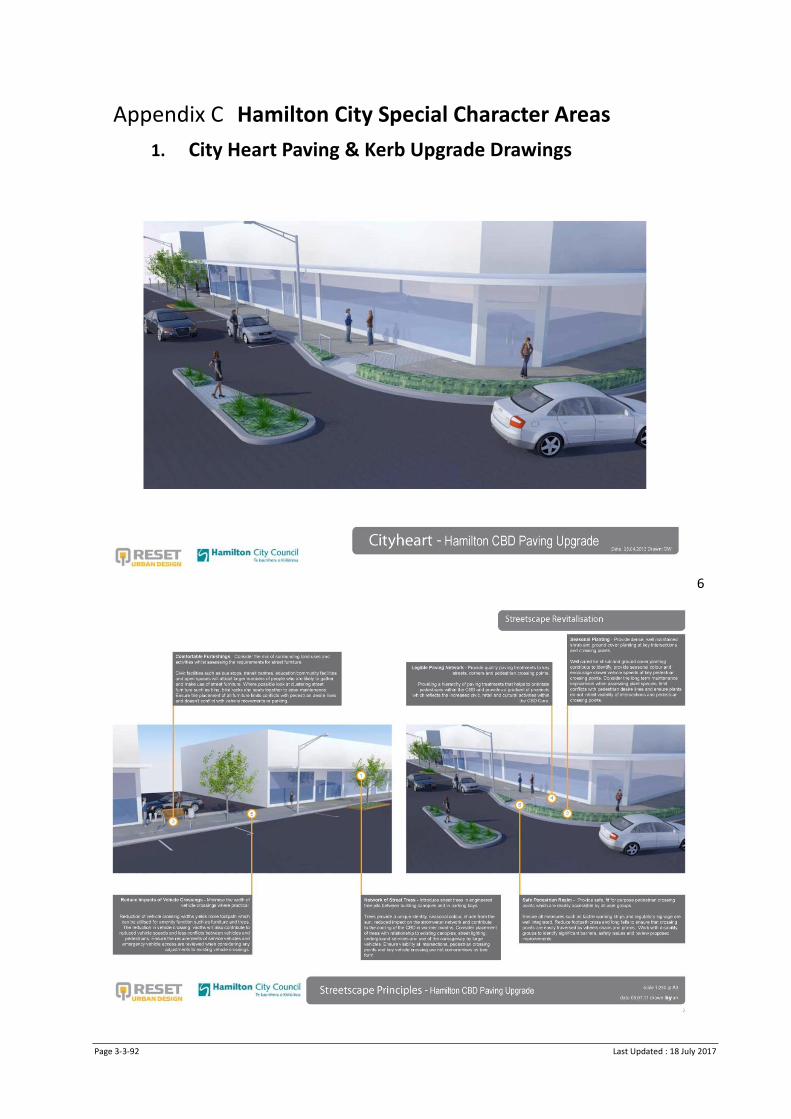
Page 3-3-92 Last Updated : 18 July 2017
Appendix C Hamilton City Special Character Areas
1. City Heart Paving & Kerb Upgrade Drawings
6

Page 3-3-93 Last Updated : 18 July 2017
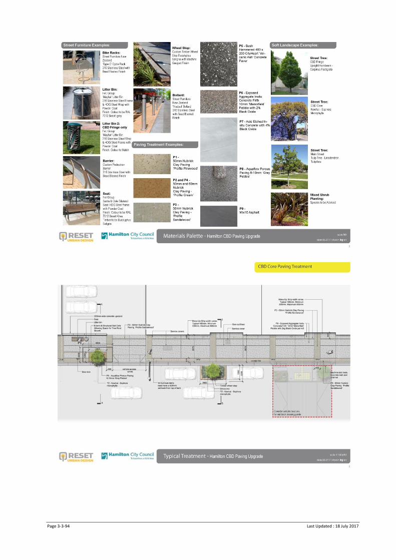
Page 3-3-94 Last Updated : 18 July 2017

Page 3-3-95 Last Updated : 18 July 2017

Page 3-3-96 Last Updated : 18 July 2017
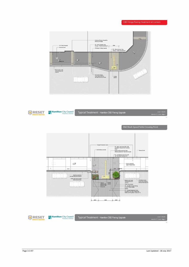
Page 3-3-97 Last Updated : 18 July 2017

Page 3-3-98 Last Updated : 18 July 2017

Page 3-3-99 Last Updated : 18 July 2017
(Insert renumbered kerb drawing - currently D3.3.4 and Deco Pole drawing – currently D3.11.3)

Page 3-3-100 Last Updated : 18 July 2017
Appendix D South Waikato Special Character Areas
1. Litter Bins
South Waikato District Council have a separation between each of the main town areas as follows: Tirau – St Louis Colonial bins, permanent green colour Putaruru – Parade Litter Bins, blue lids grey exterior Tokoroa – Tokoroa Special bins, orange colour All of the above bins are supplied by Fel. Group Ltd.

Basecourse Shape and Relative Height / Clegg Hammer Test and NDM
Checklist F3.1
Infrastructure Technical Specifications
Version : July 2017
Basecourse Shape and Relative Height / Clegg Hammer Test (Circle one test)
Subdivision ……………………………………………………………………………….. Stage ……………………………………………..……………
Plan No. ……………………………………… Ch. from ……………….…… to ……………………….…
Test Location …………………………………………………………….………..……. Road name/number ………………..…………………
Contractor ……………………………………………………………………..………… Date …………………………… Page ….... of………..
Ch 1.0m from K&C (L) Centreline 1.0m from K&C (R) Kerb Side Wheel Tracks
Left Right
Analysis of Results
Basecourse shape / Clegg hammer Test Completed (Circle one test). Clegg Hammer results attached
Remedial work required Date of calibration______________
_ Pass Ch. from: _______________ to: ________________
_ Fail Ch. from: _______________ to: ________________
Note Contractor’s control Offset pegs or Grader GPS ………………………………….
NDM Results attached …………………………………. Dry density used ………………….
Comments/Required Remedial Work
Signature of Developer/Contractor _____________________Signature of Council___________________

Subbase Shape and Relative Height /
Clegg Hammer Test F3.2 Infrastructure Technical Specifications
Version: July 2017
Subbase Shape and Relative Height / Clegg Hammer Test (Circle one test) Page ….. of………..
Subdivision ……………………………………………………………………….. Stage ……………………..……………………..………..………
Plan No. ………………………………………………………… Ch. from ………….……….…… to …….…….…………..…
Test Location …………………………………………………………….………. Road name/number …………………………….…………
Contractor ………………………………………………………………………… Date ………………………………………………..………………
Ch 1.0m from K&C (L) Centreline 1.0m from K&C (R) Kerb Side Wheel Tracks
Left Right
Analysis of Results
Subbase shape / Clegg hammer Test Completed. (Circle one test). Clegg Hammer results attached
Remedial work required Date of calibration______________
Pass Ch. from: ______________________ To: __________________________
Fail Ch. from: ______________________ To: __________________________
Note Contractor’s control Offset pegs or Grader GPS ………………………………….
Comments/Required Remedial Work
Signature of Developer/Contractor_____________________ Signature of Council________________________

Subgrade Shape and Relative Height / Scala Penetrometer Test Checklist F3.3
Infrastructure Technical Specifications
Version : July 2017
Subgrade Shape and Relative Height/ Scala Penetrometer Test Page ….. of………..
Subdivision ……………………………………………………………………….. Stage ……………………………………..………………………………
RPlan No. ………………………………………………………… Ch. from ……………….…………… To ……………….………..…
Test Location …………………………………………………………….………. Road name/number ………………………………………………
Contractor ………………………………………………………………………… Date …………………………………………………
Ch 1.0m from K&C (L) Centreline 1.0m from K&C (R) Kerb Side Wheel Tracks
Left Right
Analysis of Results
Subgrade shape / Scala Penetrometer Test. Circle one test. Scala Penetrometer test sheet attached Remedial work required
Pass Ch. from ………………… To: ………………….
Fail Ch. from: ……………….To: …………………
Note Contractor’s control Offset pegs or Grader ________________________ ______________________
Comments/Required Remedial Work
_____________________________________________________________________________________________
____________________________________________________________________________________________
Signature of Developer/Contractor_______________________Signature of Council________________________
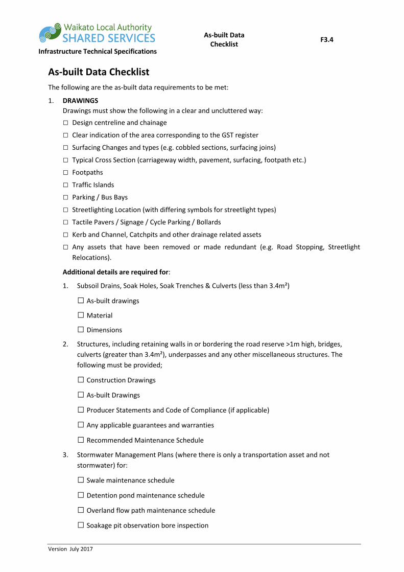
As-built Data Checklist F3.4
Infrastructure Technical Specifications
Version July 2017
As-built Data Checklist The following are the as-built data requirements to be met:
1. DRAWINGS Drawings must show the following in a clear and uncluttered way:
□ Design centreline and chainage
□ Clear indication of the area corresponding to the GST register
□ Surfacing Changes and types (e.g. cobbled sections, surfacing joins)
□ Typical Cross Section (carriageway width, pavement, surfacing, footpath etc.)
□ Footpaths
□ Traffic Islands
□ Parking / Bus Bays
□ Streetlighting Location (with differing symbols for streetlight types)
□ Tactile Pavers / Signage / Cycle Parking / Bollards
□ Kerb and Channel, Catchpits and other drainage related assets
□ Any assets that have been removed or made redundant (e.g. Road Stopping, Streetlight Relocations).
Additional details are required for:
1. Subsoil Drains, Soak Holes, Soak Trenches & Culverts (less than 3.4m²)
□ As-built drawings
□ Material
□ Dimensions
2. Structures, including retaining walls in or bordering the road reserve >1m high, bridges, culverts (greater than 3.4m²), underpasses and any other miscellaneous structures. The following must be provided;
□ Construction Drawings
□ As-built Drawings
□ Producer Statements and Code of Compliance (if applicable)
□ Any applicable guarantees and warranties
□ Recommended Maintenance Schedule
3. Stormwater Management Plans (where there is only a transportation asset and not stormwater) for:
□ Swale maintenance schedule
□ Detention pond maintenance schedule
□ Overland flow path maintenance schedule
□ Soakage pit observation bore inspection

As-built Data Checklist F3.4
Infrastructure Technical Specifications
Version July 2017
4. Detail Sheets for:
□ Asphalt or Chipseal Surfacing (including chipseal stone PSV testing sheet)
□ Pavement
□ Streetlights 2. DOCUMENTS AND FORMS
1. Structures, including bridges, culverts (greater than 3.4m²), underpasses and any other miscellaneous structures
□ Producer Statements (PS3)
□ Applicable Guarantees and Warranties
□ Recommended Maintenance Schedule
2. Streetlighting
□ Network company’s Approval
□ Electrical Certificate of Compliance
□ Manufacturer Warranty Documents for Lights, Columns and Coatings
3. As-built information, Including:
□ Streetlight Data forms
□ Pavement Data Forms
□ Asphalt or Chipseal Data Forms
Signature of Developer/Contractor_______________________ Date :

Subgrade Scala Penetrometer
Data Form F3.5
Infrastructure Technical Specifications
Version : July 2017
Subgrade Scala Penetrometer Data Form Scala penetrometer testing of subgrade materials to determine consistency.
Company Name
Tester Name
Subdivision Name and Stage
Testing Date
Testing Results
Road Name
Displacement
Location Center / Left / Right / Footpath Center / Left / Right / Footpath
Blows top 100mm
Blows 100 to 200mm
Blows 200 to 300mm
Road Name
Displacement
Location Center / Left / Right / Footpath Center / Left / Right / Footpath
Blows top 100mm
Blows 100 to 200mm
Blows 200 to 300mm
Road Name
Displacement
Location Center / Left / Right / Footpath Center / Left / Right / Footpath
Blows top 100mm
Blows 100 to 200mm
Blows 200 to 300mm

Trench Backfill Compaction Form F3.6
Infrastructure Technical Specifications
Version : July 2017
Trench Backfill Compaction Form
(to be completed for excavation reinstatement) As per the National Code of Practice for Utility Operators, sections 5.5.4 and 5.5.5 Clegg Hammer testing is required for Carriageway Basecourse and Sub-base layers, Driveways and Footpaths prior to surfacing. The target results are: Carriageway Basecourse CIV 40 Carriageway Sub-base or Driveways CIV 35 Footpaths CIV 25 Where the excavated area is greater than 0.5m² and less than 5m², one test is required, or for larger excavations, one test per 5m². For backfilling within the carriageway, testing must be carried out for each backfilled layer.
Company Name
Tester Name
CAR Number
Testing Results
Test Date
Road Name House Number / Location Layer (circle one)
Sub-base / Basecourse / Driveway / Footpath
Sub-base / Basecourse / Driveway / Footpath
Sub-base / Basecourse / Driveway / Footpath
Clegg Impact Value
Test Date
Road Name House Number / Location Layer (circle one)
Sub-base / Basecourse / Driveway / Footpath
Sub-base / Basecourse / Driveway / Footpath
Sub-base / Basecourse / Driveway / Footpath
Clegg Impact Value
Test Date
Road Name House Number / Location Layer (circle one)
Sub-base / Basecourse / Driveway / Footpath
Sub-base / Basecourse / Driveway / Footpath
Sub-base / Basecourse / Driveway / Footpath
Clegg Impact Value

Trench Backfill Compaction Form F3.6
Infrastructure Technical Specifications
Version : July 2017

RAMM Forms Asphalt Data F3.7
Infrastructure Technical Specifications
Version : July 2017
RAMM Asphalt Data (to be completed for each seal layer on each road section)
Subdivision
Road No / Name
Start m
Start Description
End m
End Description
Width
Contractor
Date of Work
Asphalt Type (circle one) AC / OGPA / SMA / Other
Grading (e.g. M/10 DG10)
Area Surfaced (m²)
Average thickness (mm)
Laying Temperature (°C) Tack Coat Residual Application Rate (L/m²) Additional Notes (e.g. Weather, Temp, Polymer Modification)

RAMM Forms Chipseal Data F3.8
Infrastructure Technical Specifications
Version : July 2017
RAMM Chipseal Data (to be completed for each seal layer on each road section)
Subdivision
Road No / Name
Start m
Start Description
End m
End Description
Width
Surfacing Chip PSV testing form attached
□
Contractor
Date of Work
Seal Type (circle one) 1 Coat / Racked in Chipseal / 2 Coat / Other:
Seal Reason Waterproofing First Coat / Second Coat / Asphalt Membrane
Area Sealed (m²)
Chip Grading (e.g. 3/5)
Binder Type (e.g. B180/200)
Chip Source Company
Chip Source Quarry
Total Volume of Binder Used (Hot) (Litres)
Temperature of Binder (°C)
Residual Binder Rate (L/m²)
Cutter (e.g. 3 pph Kero) Other Additives with concentrations (e.g. Polymer modification RS1, 3%)
Sealing Notes (e.g. Weather, Temp)

RAMM Forms Pavement Data F3.9
Infrastructure Technical Specifications
Version : July 2017
RAMM Pavement Data (to be completed for each road section)
Subdivision
Road No / Name
Start m
Start Description
End m
End Description
Width
Basecourse
Date Completed
Thickness
Grading
Quarry
Sub-Base
Date Completed
Thickness
Grading
Quarry
Undercut / Imported Subgrade (If Required)
Whole Site Yes / No
Length
Width
Depth
Backfill Material
Subgrade
CBR Without Stabilisation
Material
Stabilised? No / Cement / Lime
% Stabilising Agent
Stabilised Depth
Stabilised CBR

RAMM Forms Streetlight Data F3.10
Infrastructure Technical Specifications
Version : July 2017
RAMM Streetlight Data (to be completed for each change in streetlight type)
Subdivision and stage
Number of street lights of this type
General
Date Installed
Control Type Network Streetlight Feed / Photocell / Other:
Origin of Power Supply Streetlight Circuit / Metered Power Supply
Light
Manufacturer
Model
Total Power Consumption (W)
Light Height (m)
Tilt Angle (o Degrees)
Outreach
Outreach Type Curved / Mitre / Other Decorative:
Outreach Distance (m)
Pole
Manufacturer
Type Octagonal / Circular / Power / Other Decorative:
Pole Height (m)
Material Galvanised Steel / Steel / Other:
Coating N/A / Painted / Powder Coated
Colour (if coated)
Mounting Frangible ground plant / Shear Base
Manufacturer’s Warranty documents for Poles, Lights and Coatings attached.
Shown on as-built drawings.