Embed Size (px)
Citation preview
8/6/2019 3 Magnetic Effects of Current & Magnetism
http://slidepdf.com/reader/full/3-magnetic-effects-of-current-magnetism 1/54
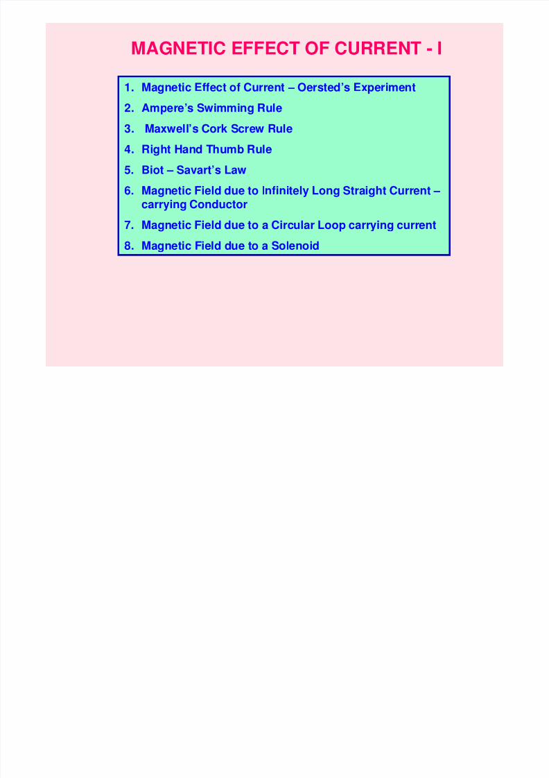
MAGNETIC EFFECT OF CURRENT - I
1. Magnetic Effect of Current – Oersted’s Experiment
2. Ampere’s Swimming Rule
3. Maxwell’s Cork Screw Rule
4. Right Hand Thumb Rule
5. Biot – Savart’s Law
6. Magnetic Field due to Infinitely Long Straight Current –
carrying Conductor
7. Magnetic Field due to a Circular Loop carrying current
8. Magnetic Field due to a Solenoid
8/6/2019 3 Magnetic Effects of Current & Magnetism
http://slidepdf.com/reader/full/3-magnetic-effects-of-current-magnetism 2/54
N
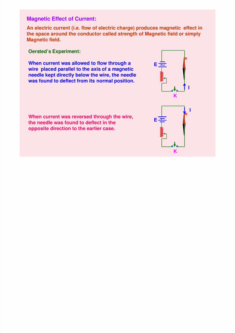
Magnetic Effect of Current:
An electric current (i.e. flow of electric charge) produces magnetic effect inthe space around the conductor called strength of Magnetic field or simplyMagnetic field.
Oersted’s Experiment:
When current was allowed to flow through awire placed parallel to the axis of a magneticneedle kept directly below the wire, the needlewas found to deflect from its normal position.
E
KI
N
K
I
EWhen current was reversed through the wire,the needle was found to deflect in theopposite direction to the earlier case.
8/6/2019 3 Magnetic Effects of Current & Magnetism
http://slidepdf.com/reader/full/3-magnetic-effects-of-current-magnetism 3/54
BB
N
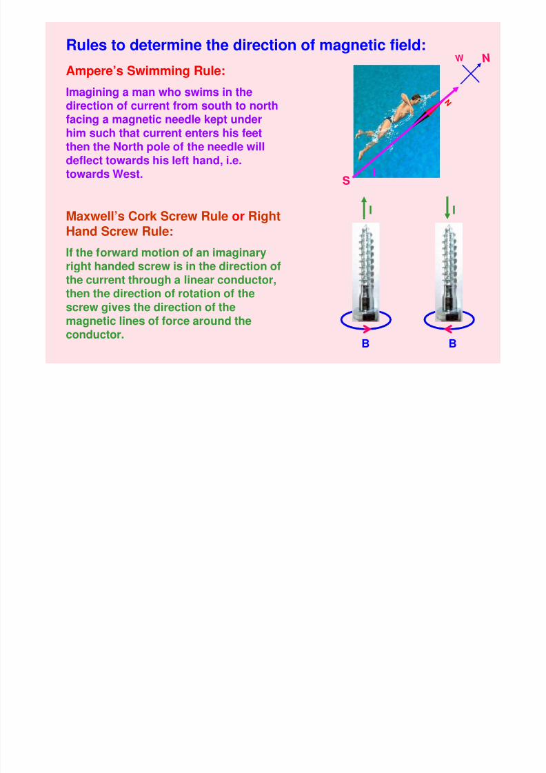
Rules to determine the direction of magnetic field:
Ampere’s Swimming Rule:
Imagining a man who swims in thedirection of current from south to northfacing a magnetic needle kept under
him such that current enters his feetthen the North pole of the needle willdeflect towards his left hand, i.e.towards West.
Maxwell’s Cork Screw Rule or RightHand Screw Rule:
If the forward motion of an imaginary
right handed screw is in the direction ofthe current through a linear conductor,then the direction of rotation of thescrew gives the direction of themagnetic lines of force around the
conductor.
S
N W
I
I I
8/6/2019 3 Magnetic Effects of Current & Magnetism
http://slidepdf.com/reader/full/3-magnetic-effects-of-current-magnetism 4/54
x
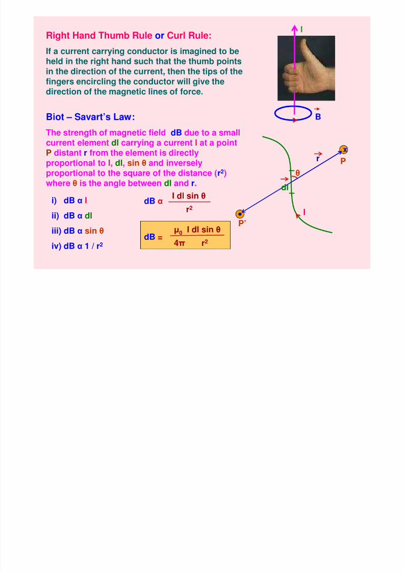
Right Hand Thumb Rule or Curl Rule:
If a current carrying conductor is imagined to beheld in the right hand such that the thumb pointsin the direction of the current, then the tips of thefingers encircling the conductor will give thedirection of the magnetic lines of force.
I
Biot – Savart’s Law:
The strength of magnetic field dB due to a smallcurrent element dl carrying a current I at a point
P distant r from the element is directlyproportional to I, dl, sin θ and inverselyproportional to the square of the distance (r2)where θ is the angle between dl and r.
θ
P
dl
r
i) dB α I
ii) dB α dl
iii) dB α sin θ
iv) dB α 1 / r2
dB αI dl sin θ
r2
dB =µ0 I dl sin θ
4π r2
P’
B
I
8/6/2019 3 Magnetic Effects of Current & Magnetism
http://slidepdf.com/reader/full/3-magnetic-effects-of-current-magnetism 5/54
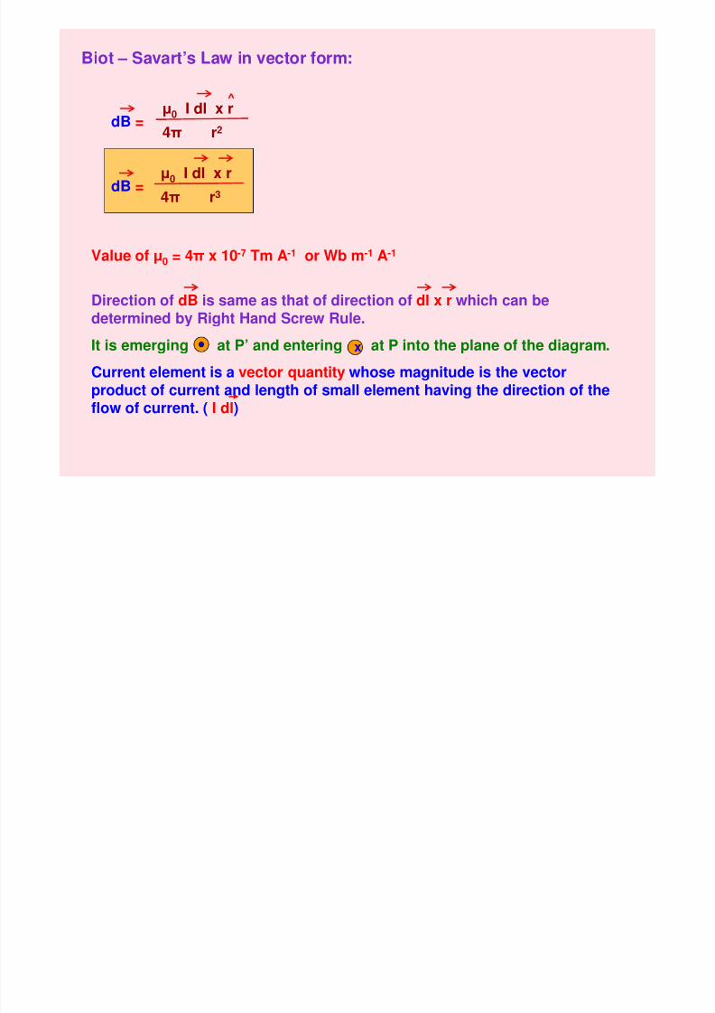
Biot – Savart’s Law in vector form:
dB =µ0 I dl x r
4π r2
dB = µ0 I dl x r4π r3
Value of µ0 = 4π x 10-7 Tm A-1 or Wb m-1 A-1
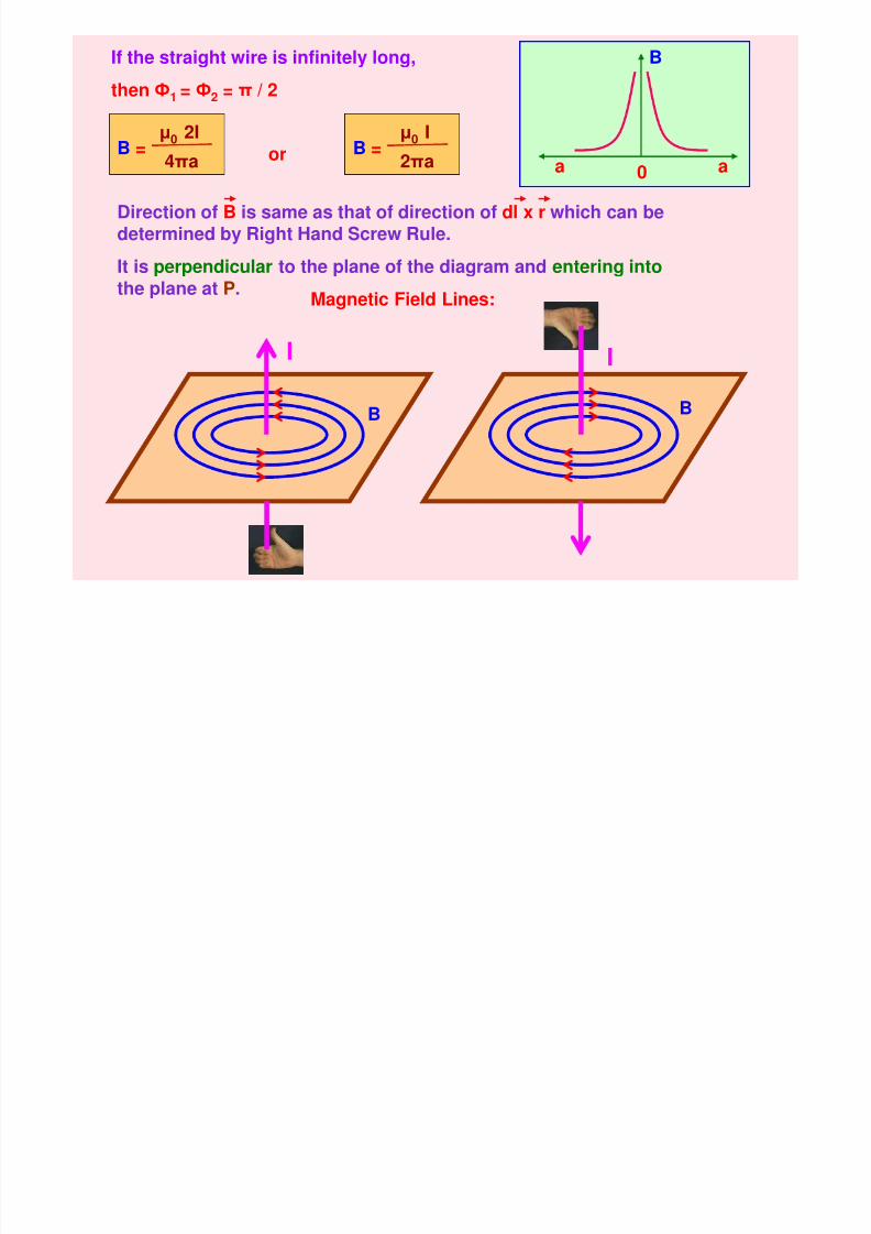
Direction of dB is same as that of direction of dl x r which can bedetermined by Right Hand Screw Rule.
It is emerging at P’ and entering at P into the plane of the diagram.
Current element is a vector quantity whose magnitude is the vectorproduct of current and length of small element having the direction of theflow of current. ( I dl)
x
8/6/2019 3 Magnetic Effects of Current & Magnetism
http://slidepdf.com/reader/full/3-magnetic-effects-of-current-magnetism 6/54
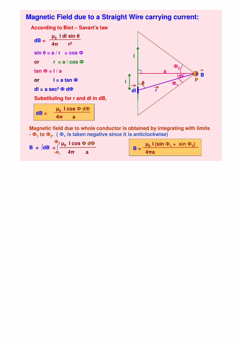
Magnetic Field due to a Straight Wire carrying current:
Pθ
r
a
I
Ф2
Ф1
Фl
According to Biot – Savart’s law
dB =µ0 I dl sin θ
4π r2
sin θ = a / r = cos Ф
or r = a / cos Ф
tan Ф = l / a
or l = a tan Ф
dl = a sec2
Ф dФSubstituting for r and dl in dB,
dB =µ0 I cos Ф dФ
4π a
Magnetic field due to whole conductor is obtained by integrating with limits- Ф1 to Ф2. ( Ф1 is taken negative since it is anticlockwise)
µ0 I cos Ф dФ
4π aB = ∫dB = ∫
-Ф1
Ф2
B =
µ0 I (sin Ф1 + sin Ф2)
4πa
dl
x B
8/6/2019 3 Magnetic Effects of Current & Magnetism
http://slidepdf.com/reader/full/3-magnetic-effects-of-current-magnetism 7/54
8/6/2019 3 Magnetic Effects of Current & Magnetism
http://slidepdf.com/reader/full/3-magnetic-effects-of-current-magnetism 8/54
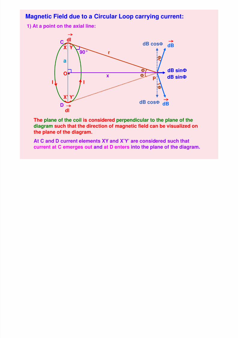
Magnetic Field due to a Circular Loop carrying current:
1) At a point on the axial line:
O
a
r
dB
dB
dB cosФ
dB sinФ
I I
dlCX Y
dlD
X’ Y’
90°
Ф
Ф
Ф
Фx
The plane of the coil is considered perpendicular to the plane of thediagram such that the direction of magnetic field can be visualized onthe plane of the diagram.
At C and D current elements XY and X’Y’ are considered such that
current at C emerges out and at D enters into the plane of the diagram.
P
dB cosФ
dB sinФ
8/6/2019 3 Magnetic Effects of Current & Magnetism
http://slidepdf.com/reader/full/3-magnetic-effects-of-current-magnetism 9/54
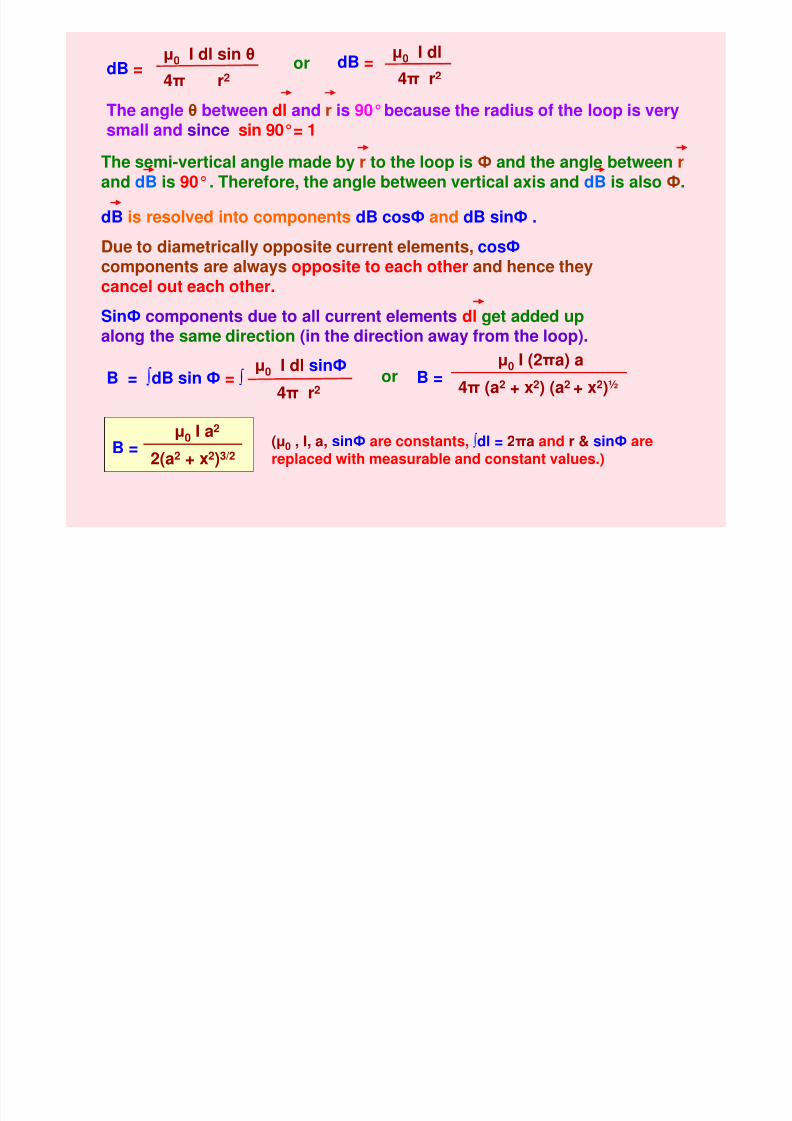
dB =µ0 I dl sin θ
4π r2
dB =µ0 I dl
4π r2
µ0 I dl sinФ
4π r2
B = ∫dB sin Ф = ∫ or B =µ0 I (2πa) a
4π (a2
+ x2
) (a2
+ x2
)½
B =µ0 I a2
2(a2 + x2)3/2(µ0 , I, a, sinФ are constants, ∫dl = 2πa and r & sinФ arereplaced with measurable and constant values.)
or
The angle θ between dl and r is 90°because the radius of the loop is verysmall and since sin 90°= 1
The semi-vertical angle made by r to the loop is Ф and the angle between rand dB is 90°. Therefore, the angle between vertical axis and dB is also Ф.
dB is resolved into components dB cosФ and dB sinФ .
Due to diametrically opposite current elements, cosФcomponents are always opposite to each other and hence theycancel out each other.
SinФ components due to all current elements dl get added upalong the same direction (in the direction away from the loop).
8/6/2019 3 Magnetic Effects of Current & Magnetism
http://slidepdf.com/reader/full/3-magnetic-effects-of-current-magnetism 10/54
I
I I
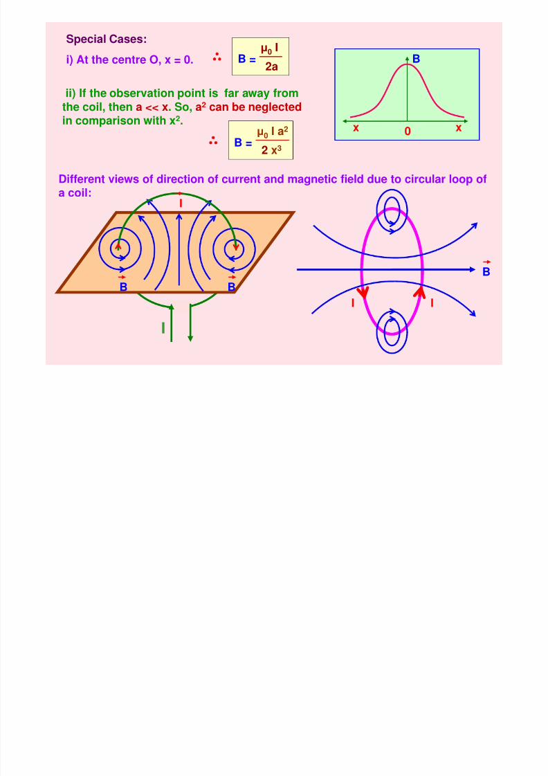
Different views of direction of current and magnetic field due to circular loop ofa coil:
B
xx 0
ii) If the observation point is far away fromthe coil, then a << x. So, a2 can be neglectedin comparison with x2.
B =µ
0I a2
2 x3
Special Cases:
i) At the centre O, x = 0. B =µ0 I
2a
I
B BB
8/6/2019 3 Magnetic Effects of Current & Magnetism
http://slidepdf.com/reader/full/3-magnetic-effects-of-current-magnetism 11/54
x
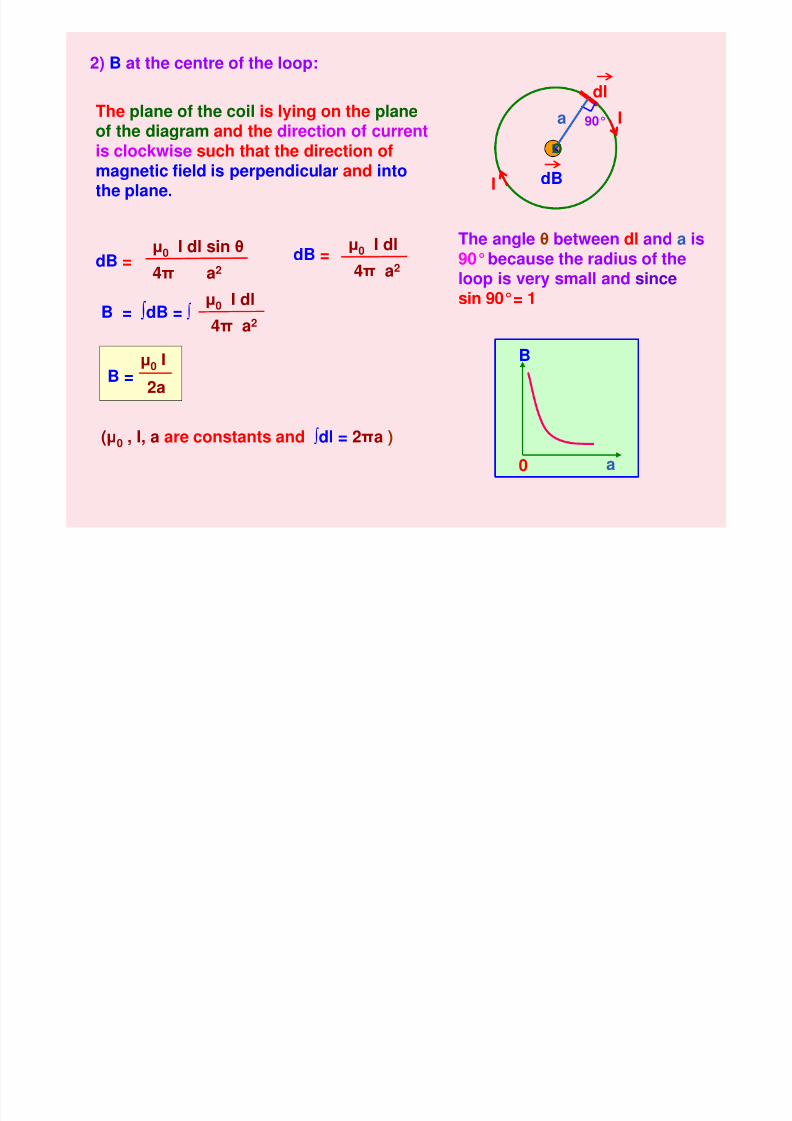
2) B at the centre of the loop:
dB
The plane of the coil is lying on the planeof the diagram and the direction of currentis clockwise such that the direction ofmagnetic field is perpendicular and into
the plane.
dB =µ0 I dl sin θ
4π a2
I
Idl
90°
dB =µ0 I dl
4π a2
The angle θ between dl and a is90°because the radius of theloop is very small and since
sin 90°= 1B = ∫dB = ∫ µ0 I dl
4π a2
B =µ0 I
2a
(µ0 , I, a are constants and ∫dl = 2πa )
a
O
B
a0
8/6/2019 3 Magnetic Effects of Current & Magnetism
http://slidepdf.com/reader/full/3-magnetic-effects-of-current-magnetism 12/54
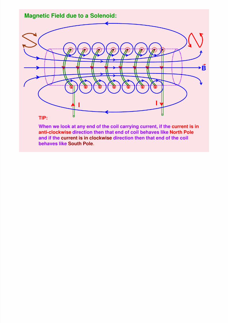
Magnetic Field due to a Solenoid:
I I
xxxxx xx
TIP:
When we look at any end of the coil carrying current, if the current is inanti-clockwise direction then that end of coil behaves like North Poleand if the current is in clockwise direction then that end of the coil
behaves like South Pole.
B
8/6/2019 3 Magnetic Effects of Current & Magnetism
http://slidepdf.com/reader/full/3-magnetic-effects-of-current-magnetism 13/54
MAGNETIC EFFECT OF CURRENT - II
1. Lorentz Magnetic Force
2. Fleming’s Left Hand Rule
3. Force on a moving charge in uniform Electric and Magnetic fields
4. Force on a current carrying conductor in a uniform Magnetic Field
5. Force between two infinitely long parallel current-carryingconductors
6. Definition of ampere
7. Representation of fields due to parallel currents
8. Torque experienced by a current-carrying coil in a uniformMagnetic Field
9. Moving Coil Galvanometer
10.Conversion of Galvanometer into Ammeter and Voltmeter
11.Differences between Ammeter and Voltmeter
8/6/2019 3 Magnetic Effects of Current & Magnetism
http://slidepdf.com/reader/full/3-magnetic-effects-of-current-magnetism 14/54
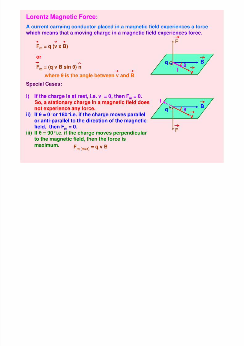
Lorentz Magnetic Force:
A current carrying conductor placed in a magnetic field experiences a force
which means that a moving charge in a magnetic field experiences force.
Fm = q (v x B)
+q B
v
F
Iθ
-qB
v
F
θ
Fm = (q v B sin θ) n
where θ is the angle between v and B
Special Cases:
i) If the charge is at rest, i.e. v = 0, then Fm = 0.So, a stationary charge in a magnetic field doesnot experience any force.
ii) If θ = 0°or 180°i.e. if the charge moves parallel
or anti-parallel to the direction of the magneticfield, then Fm = 0.iii) If θ = 90°i.e. if the charge moves perpendicular
to the magnetic field, then the force ismaximum. Fm (max) = q v B
or
I
8/6/2019 3 Magnetic Effects of Current & Magnetism
http://slidepdf.com/reader/full/3-magnetic-effects-of-current-magnetism 15/54
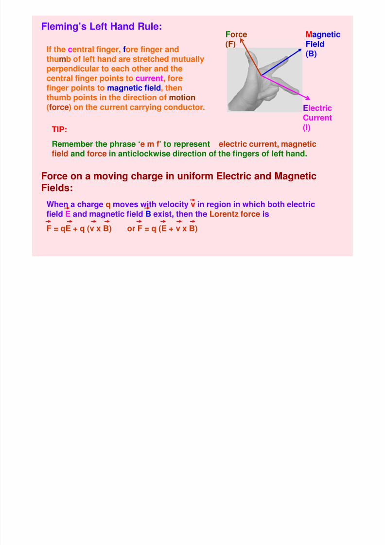
Fleming’s Left Hand Rule:Force(F)
MagneticField(B)
ElectricCurrent(I)
If the central finger, fore finger andthumb of left hand are stretched mutuallyperpendicular to each other and thecentral finger points to current, forefinger points to magnetic field, then
thumb points in the direction of motion(force) on the current carrying conductor.
TIP:
Remember the phrase ‘e m f’ to represent electric current, magneticfield and force in anticlockwise direction of the fingers of left hand.
Force on a moving charge in uniform Electric and Magnetic
Fields:When a charge q moves with velocity v in region in which both electricfield E and magnetic field B exist, then the Lorentz force is
F = qE + q (v x B) or F = q (E + v x B)
8/6/2019 3 Magnetic Effects of Current & Magnetism
http://slidepdf.com/reader/full/3-magnetic-effects-of-current-magnetism 16/54
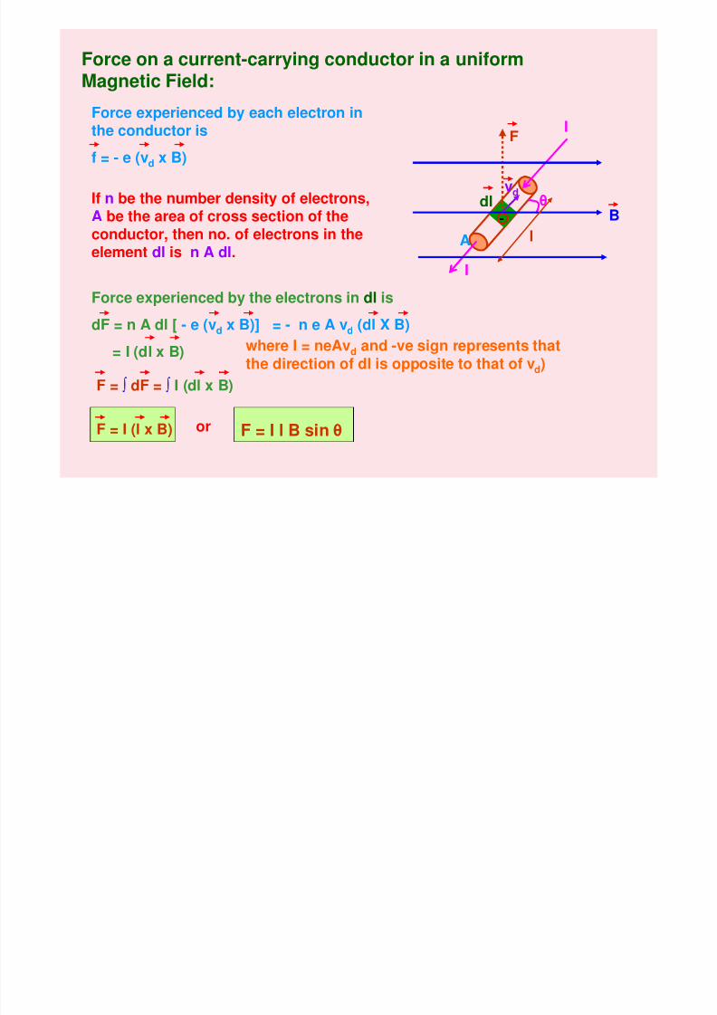
Force on a current-carrying conductor in a uniformMagnetic Field:
θvd
dl
F
I
I
B
A l
Force experienced by each electron inthe conductor is
f = - e (vd x B)
If n be the number density of electrons,A be the area of cross section of theconductor, then no. of electrons in theelement dl is n A dl.
where I = neAvd and -ve sign represents that
the direction of dl is opposite to that of vd)
or F = I l B sin θ
-
Force experienced by the electrons in dl is
dF = n A dl [ - e (vd x B)] = - n e A vd (dl X B)
= I (dl x B)
F = ∫ dF = ∫ I (dl x B)
F = I (l x B)
8/6/2019 3 Magnetic Effects of Current & Magnetism
http://slidepdf.com/reader/full/3-magnetic-effects-of-current-magnetism 17/54
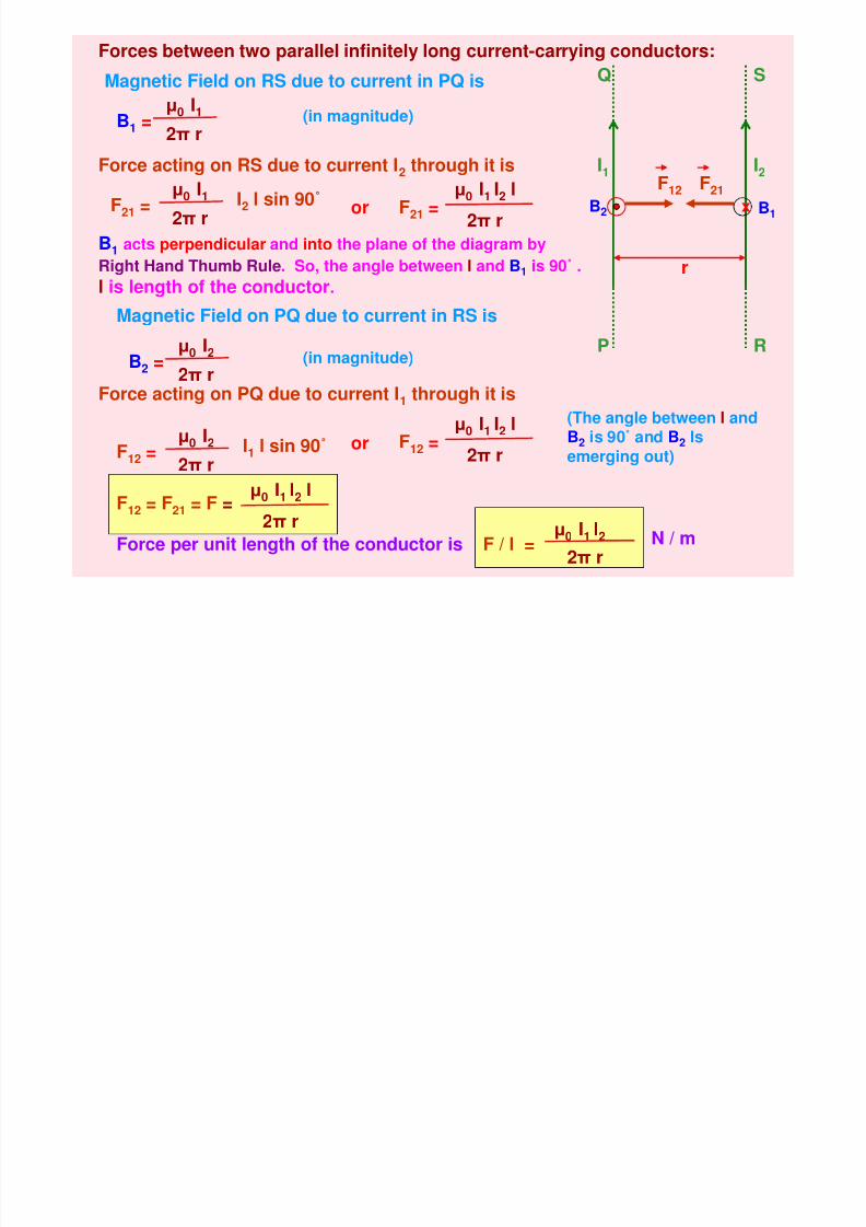
Forces between two parallel infinitely long current-carrying conductors:
r
F21F12
I1
P
Q
I2
S
R
B1 = µ0 I12π r
Magnetic Field on RS due to current in PQ is
Force acting on RS due to current I2 through it is
F21 =µ0 I1
2π r
I2 l sin 90˚
B1 acts perpendicular and into the plane of the diagram by
Right Hand Thumb Rule. So, the angle between l and B1 is 90˚ .
l is length of the conductor.
F21
=µ0 I1 I2 l
2π r
B2 =µ0 I2
2π r
Magnetic Field on PQ due to current in RS is
Force acting on PQ due to current I1 through it is
F12 = µ0 I2
2π rI1 l sin 90˚ F12 =
µ0
I1I2
l
2π r
(The angle between l and
B2 is 90˚ and B2 Isemerging out)
F12 = F21 = F =µ0 I1 I2 l
2π r
F / l =µ
0
I1
I2
2π r
or
or
Force per unit length of the conductor is N / m
(in magnitude)
(in magnitude)
x B1
B2
8/6/2019 3 Magnetic Effects of Current & Magnetism
http://slidepdf.com/reader/full/3-magnetic-effects-of-current-magnetism 18/54
r
F
I1
P
Q
F
I2
x
S
R
r I2
Fx
S
R
I1
F
P
Q
x
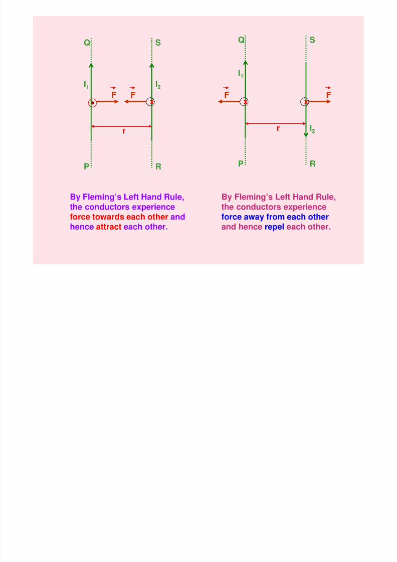
By Fleming’s Left Hand Rule,the conductors experienceforce towards each other andhence attract each other.
By Fleming’s Left Hand Rule,the conductors experienceforce away from each otherand hence repel each other.
8/6/2019 3 Magnetic Effects of Current & Magnetism
http://slidepdf.com/reader/full/3-magnetic-effects-of-current-magnetism 19/54
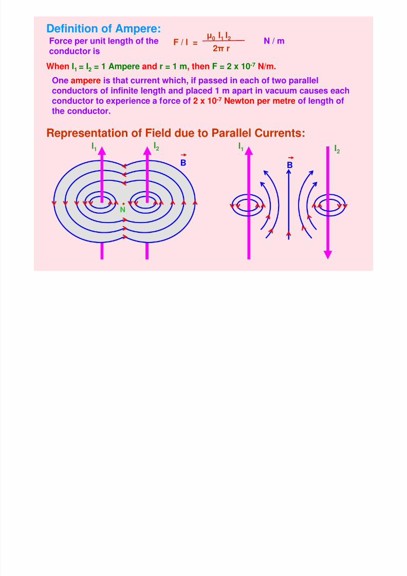
Definition of Ampere:F / l =
µ0 I1 I2
2π r
Force per unit length of the
conductor is
N / m
When I1 = I2 = 1 Ampere and r = 1 m, then F = 2 x 10⁻⁷ N/m.
One ampere is that current which, if passed in each of two parallelconductors of infinite length and placed 1 m apart in vacuum causes each
conductor to experience a force of 2 x 10⁻⁷
Newton per metre of length ofthe conductor.
Representation of Field due to Parallel Currents:I1 I
2
B
I1 I2
B
N
8/6/2019 3 Magnetic Effects of Current & Magnetism
http://slidepdf.com/reader/full/3-magnetic-effects-of-current-magnetism 20/54
B
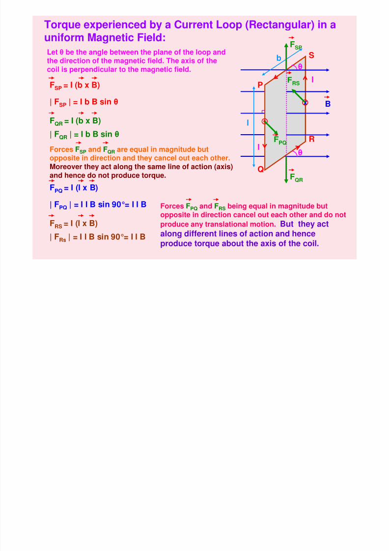
Torque experienced by a Current Loop (Rectangular) in auniform Magnetic Field:
P
Q
R
S
x
θ
θ
Let θ be the angle between the plane of the loop andthe direction of the magnetic field. The axis of thecoil is perpendicular to the magnetic field.
l
b
I
I
| FSP | = I b B sin θ
| FQR | = I b B sin θ
| FPQ | = I l B sin 90°= I l B
| FRs | = I l B sin 90°= I l B
FSP = I (b x B)
FQR = I (b x B)
FPQ = I (l x B)
Forces FSP and FQR are equal in magnitude butopposite in direction and they cancel out each other.Moreover they act along the same line of action (axis)and hence do not produce torque.
FRS = I (l x B)
Forces FPQ and FRS being equal in magnitude butopposite in direction cancel out each other and do not
produce any translational motion. But they actalong different lines of action and hence
produce torque about the axis of the coil.
FQR
FSP
FPQ
FRS
8/6/2019 3 Magnetic Effects of Current & Magnetism
http://slidepdf.com/reader/full/3-magnetic-effects-of-current-magnetism 21/54
P
Q
R
Sxb
θ
θ N
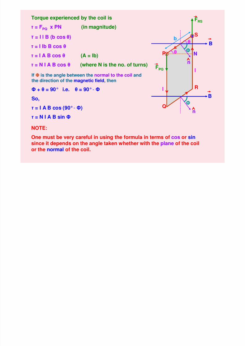
Torque experienced by the coil is
ז = FPQ x PN (in magnitude)
ז = I l B (b cos θ)
ז = I lb B cos θ
ז = I A B cos θ (A = lb)
ז = N I A B cos θ (where N is the no. of turns)
If Φ is the angle between the normal to the coil andthe direction of the magnetic field, then
Φ + θ = 90° i.e. θ = 90°- Φ
So,
ז = I A B cos (90°- Φ)
ז = N I A B sin Φ
NOTE:
One must be very careful in using the formula in terms of cos or sinsince it depends on the angle taken whether with the plane of the coilor the normal of the coil.
Φ
Φ
B
B
FPQ
FRS
n
n
I
I
8/6/2019 3 Magnetic Effects of Current & Magnetism
http://slidepdf.com/reader/full/3-magnetic-effects-of-current-magnetism 22/54
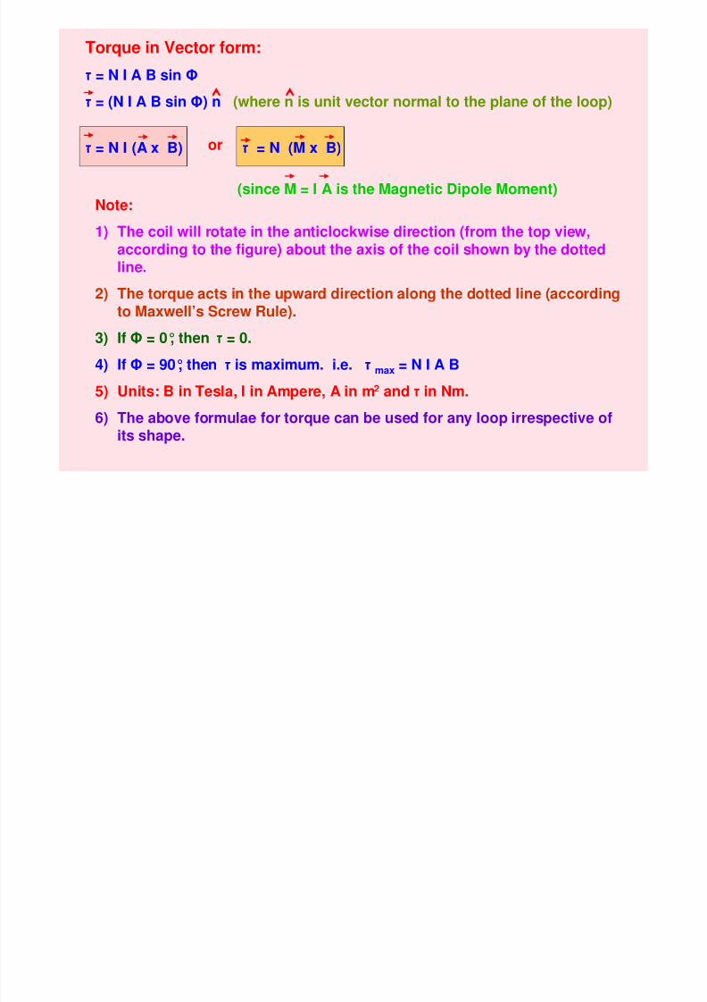
Note:
1) The coil will rotate in the anticlockwise direction (from the top view,according to the figure) about the axis of the coil shown by the dotted
line.
2) The torque acts in the upward direction along the dotted line (accordingto Maxwell’s Screw Rule).
3) If Φ = 0°, then ז = 0.
4) If Φ = 90°, then ז is maximum. i.e. ז max = N I A B
5) Units: B in Tesla, I in Ampere, A in m2 and ז in Nm.
6) The above formulae for torque can be used for any loop irrespective ofits shape.
or
(since M = I A is the Magnetic Dipole Moment)
ז = N I (A x B) ז = N (M x B)
Torque in Vector form:
ז = N I A B sin Φ
ז = (N I A B sin Φ) n (where n is unit vector normal to the plane of the loop)
8/6/2019 3 Magnetic Effects of Current & Magnetism
http://slidepdf.com/reader/full/3-magnetic-effects-of-current-magnetism 23/54
PBW
P S
Q R
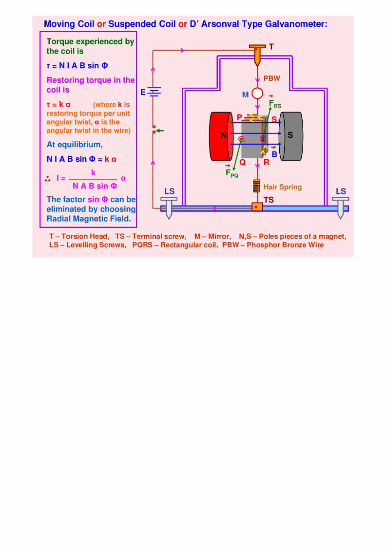
Moving Coil or Suspended Coil or D’ Arsonval Type Galvanometer:
N Sx
T
E
T – Torsion Head, TS – Terminal screw, M – Mirror, N,S – Poles pieces of a magnet,
LS – Levelling Screws, PQRS – Rectangular coil, PBW – Phosphor Bronze Wire
LS LS
B
Torque experienced by
the coil is
ז = N I A B sin Φ
Restoring torque in thecoil is
ז = k α (where k isrestoring torque per unitangular twist, α is theangular twist in the wire)
At equilibrium,N I A B sin Φ = k α
I =k
N A B sin Φα
The factor sin Φ can beeliminated by choosingRadial Magnetic Field.
M
Hair Spring
TS
FRS
FPQ
8/6/2019 3 Magnetic Effects of Current & Magnetism
http://slidepdf.com/reader/full/3-magnetic-effects-of-current-magnetism 24/54
Lamp
Scale
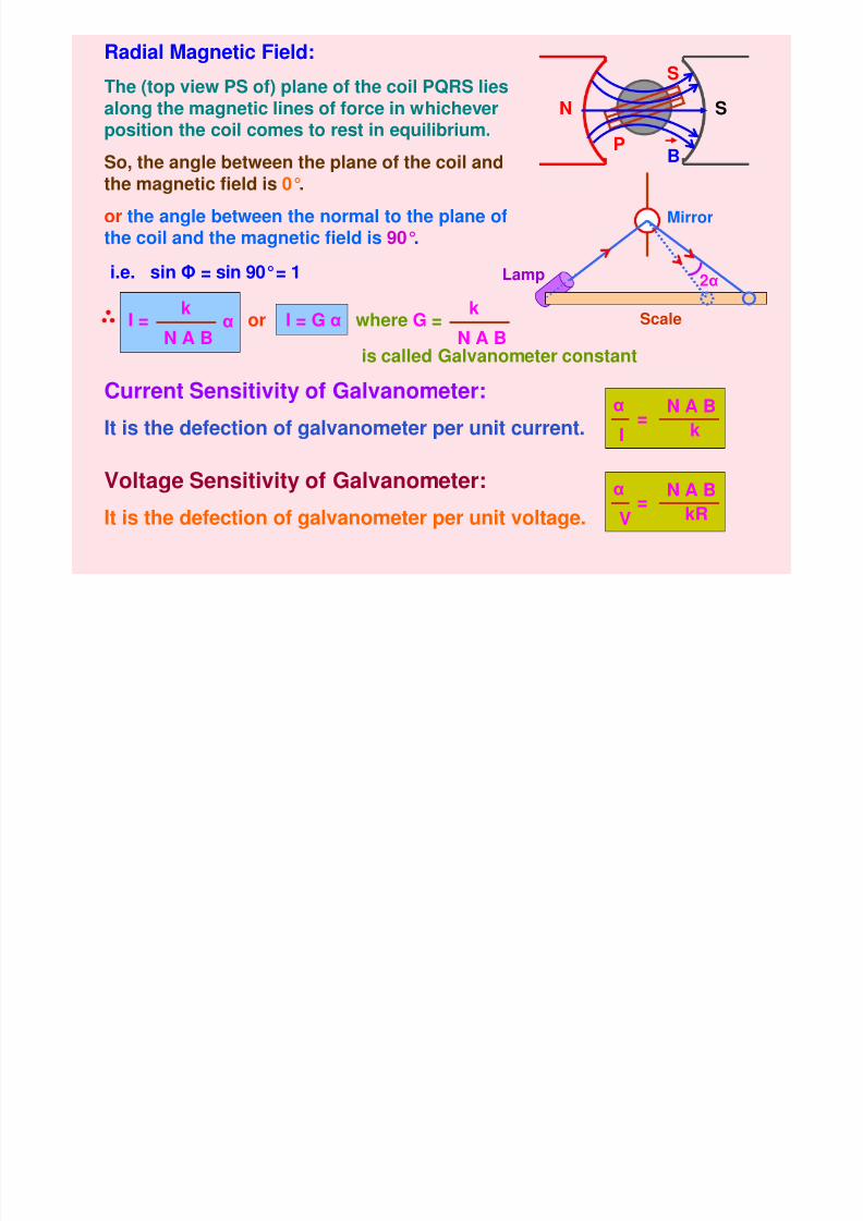
Radial Magnetic Field:
N S
BP
SThe (top view PS of) plane of the coil PQRS lies
along the magnetic lines of force in whicheverposition the coil comes to rest in equilibrium.
So, the angle between the plane of the coil andthe magnetic field is 0°.
or the angle between the normal to the plane ofthe coil and the magnetic field is 90°.
i.e. sin Φ = sin 90°= 1
I =
k
N A B α or I = G α
k
N A Bwhere G =is called Galvanometer constant
Current Sensitivity of Galvanometer:
It is the defection of galvanometer per unit current. k
N A B
I
α=
Voltage Sensitivity of Galvanometer:
It is the defection of galvanometer per unit voltage. kR
N A B
V
α=
Mirror
2α
8/6/2019 3 Magnetic Effects of Current & Magnetism
http://slidepdf.com/reader/full/3-magnetic-effects-of-current-magnetism 25/54
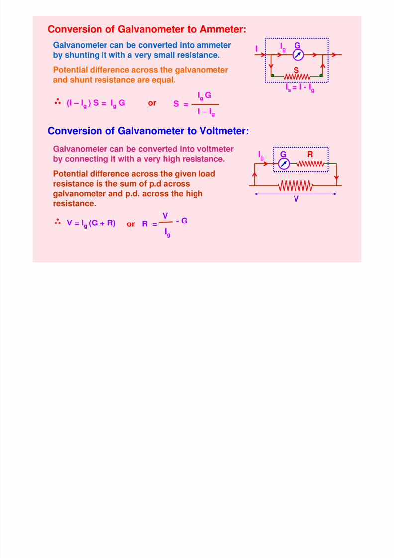
Conversion of Galvanometer to Ammeter:
Galvanometer can be converted into ammeter
by shunting it with a very small resistance.
Potential difference across the galvanometerand shunt resistance are equal.
(I – Ig ) S = Ig G S =Ig
G
I – Ig
Conversion of Galvanometer to Voltmeter:
Galvanometer can be converted into voltmeterby connecting it with a very high resistance.
Potential difference across the given loadresistance is the sum of p.d acrossgalvanometer and p.d. across the highresistance.
V = Ig (G + R)
GI
Ig
Is = I - Ig
S
or R =V
Ig
- G
GIg R
V
or
8/6/2019 3 Magnetic Effects of Current & Magnetism
http://slidepdf.com/reader/full/3-magnetic-effects-of-current-magnetism 26/54
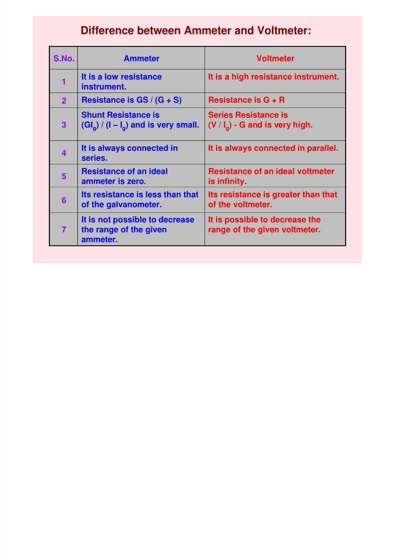
Difference between Ammeter and Voltmeter:
It is possible to decrease therange of the given voltmeter.
It is not possible to decreasethe range of the givenammeter.
7
Its resistance is greater than thatof the voltmeter.
Its resistance is less than thatof the galvanometer.6
Resistance of an ideal voltmeteris infinity.
Resistance of an idealammeter is zero.
5
It is always connected in parallel.It is always connected inseries.4
Series Resistance is(V / Ig) - G and is very high.
Shunt Resistance is(GIg) / (I – Ig) and is very small.3
Resistance is G + RResistance is GS / (G + S)2
It is a high resistance instrument.It is a low resistanceinstrument.
1
VoltmeterAmmeterS.No.
8/6/2019 3 Magnetic Effects of Current & Magnetism
http://slidepdf.com/reader/full/3-magnetic-effects-of-current-magnetism 27/54
MAGNETIC EFFECT OF CURRENT - III
1. Cyclotron
2. Ampere’s Circuital Law
3. Magnetic Field due to a Straight Solenoid
4. Magnetic Field due to a Toroidal Solenoid
8/6/2019 3 Magnetic Effects of Current & Magnetism
http://slidepdf.com/reader/full/3-magnetic-effects-of-current-magnetism 28/54
N
S
D1 D2+
W
B
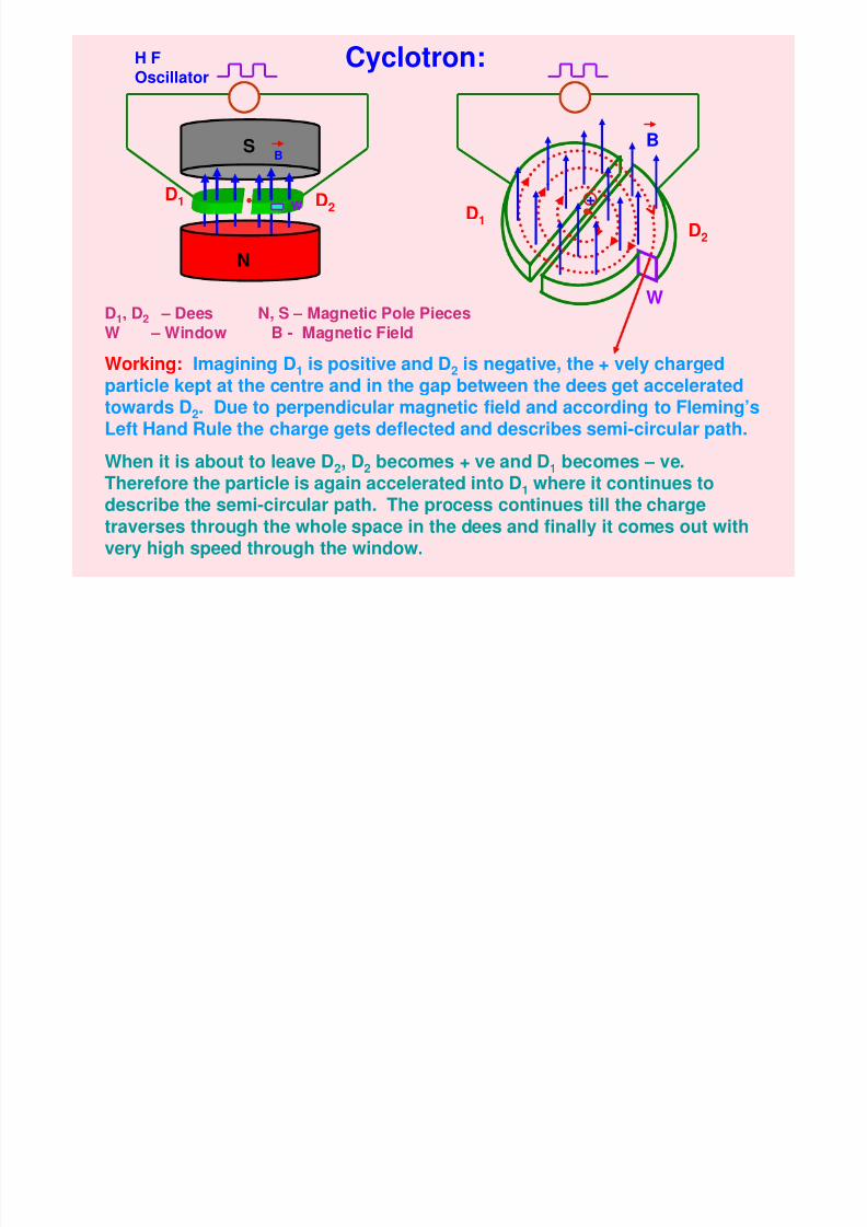
Cyclotron:
D1, D2 – Dees N, S – Magnetic Pole Pieces
W – Window B - Magnetic Field
H FOscillator
D2D1
Working: Imagining D1 is positive and D2 is negative, the + vely chargedparticle kept at the centre and in the gap between the dees get acceleratedtowards D2. Due to perpendicular magnetic field and according to Fleming’s
Left Hand Rule the charge gets deflected and describes semi-circular path.When it is about to leave D2, D2 becomes + ve and D1 becomes – ve.Therefore the particle is again accelerated into D1 where it continues todescribe the semi-circular path. The process continues till the chargetraverses through the whole space in the dees and finally it comes out with
very high speed through the window.
W
B
8/6/2019 3 Magnetic Effects of Current & Magnetism
http://slidepdf.com/reader/full/3-magnetic-effects-of-current-magnetism 29/54
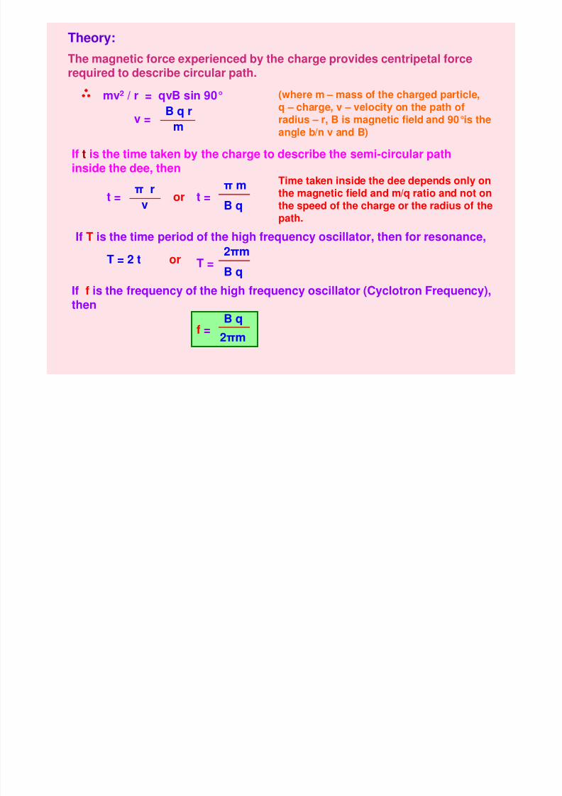
Theory:
The magnetic force experienced by the charge provides centripetal force
required to describe circular path.
mv2 / r = qvB sin 90° (where m – mass of the charged particle,q – charge, v – velocity on the path ofradius – r, B is magnetic field and 90°is theangle b/n v and B)
v =B q r
m
If t is the time taken by the charge to describe the semi-circular pathinside the dee, then
t =π r
vor t =
π m
B q
Time taken inside the dee depends only onthe magnetic field and m/q ratio and not onthe speed of the charge or the radius of the
path.
If T is the time period of the high frequency oscillator, then for resonance,
T = 2 t or T =2πm
B q
If f is the frequency of the high frequency oscillator (Cyclotron Frequency),then
f =2πm
B q
8/6/2019 3 Magnetic Effects of Current & Magnetism
http://slidepdf.com/reader/full/3-magnetic-effects-of-current-magnetism 30/54
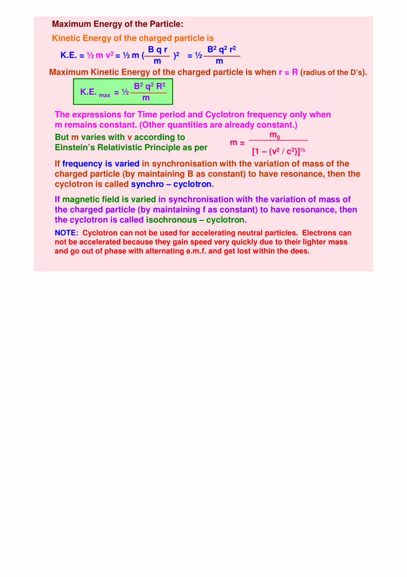
Maximum Energy of the Particle:
Kinetic Energy of the charged particle is
K.E. = ½ m v2 = ½ m (B q r
m )2 = ½B2 q2 r2
m
Maximum Kinetic Energy of the charged particle is when r = R (radius of the D’s).
= ½B2 q2 R2
mK.E. max
The expressions for Time period and Cyclotron frequency only whenm remains constant. (Other quantities are already constant.)
m =m0
[1 – (v2
/ c2
)]½
If frequency is varied in synchronisation with the variation of mass of thecharged particle (by maintaining B as constant) to have resonance, then thecyclotron is called synchro – cyclotron.
If magnetic field is varied in synchronisation with the variation of mass of
the charged particle (by maintaining f as constant) to have resonance, thenthe cyclotron is called isochronous – cyclotron.
NOTE: Cyclotron can not be used for accelerating neutral particles. Electrons cannot be accelerated because they gain speed very quickly due to their lighter massand go out of phase with alternating e.m.f. and get lost within the dees.
But m varies with v according toEinstein’s Relativistic Principle as per
8/6/2019 3 Magnetic Effects of Current & Magnetism
http://slidepdf.com/reader/full/3-magnetic-effects-of-current-magnetism 31/54
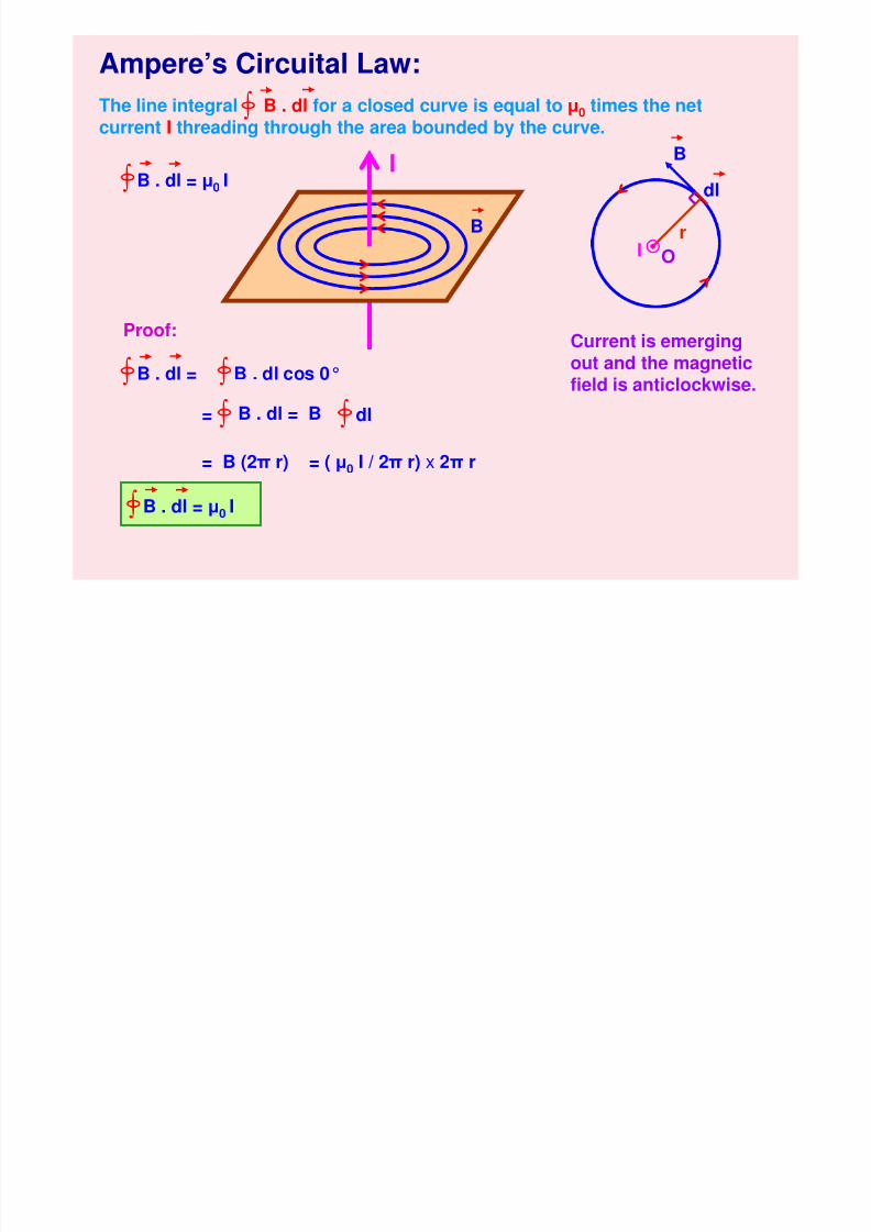
Ampere’s Circuital Law:
The line integral B . dl for a closed curve is equal to µ0
times the netcurrent I threading through the area bounded by the curve.∫
∫ B . dl = µ0 I
∫ B . dl = ∫ B . dl cos 0°
∫ B . dl = B= ∫ dl
= B (2π r) = ( µ0 I / 2π r) x 2π r
∫ B . dl = µ0 I
I
B
B
r
O
dl
I
Current is emergingout and the magneticfield is anticlockwise.
Proof:
M i Fi ld h f S i h S l id
8/6/2019 3 Magnetic Effects of Current & Magnetism
http://slidepdf.com/reader/full/3-magnetic-effects-of-current-magnetism 32/54
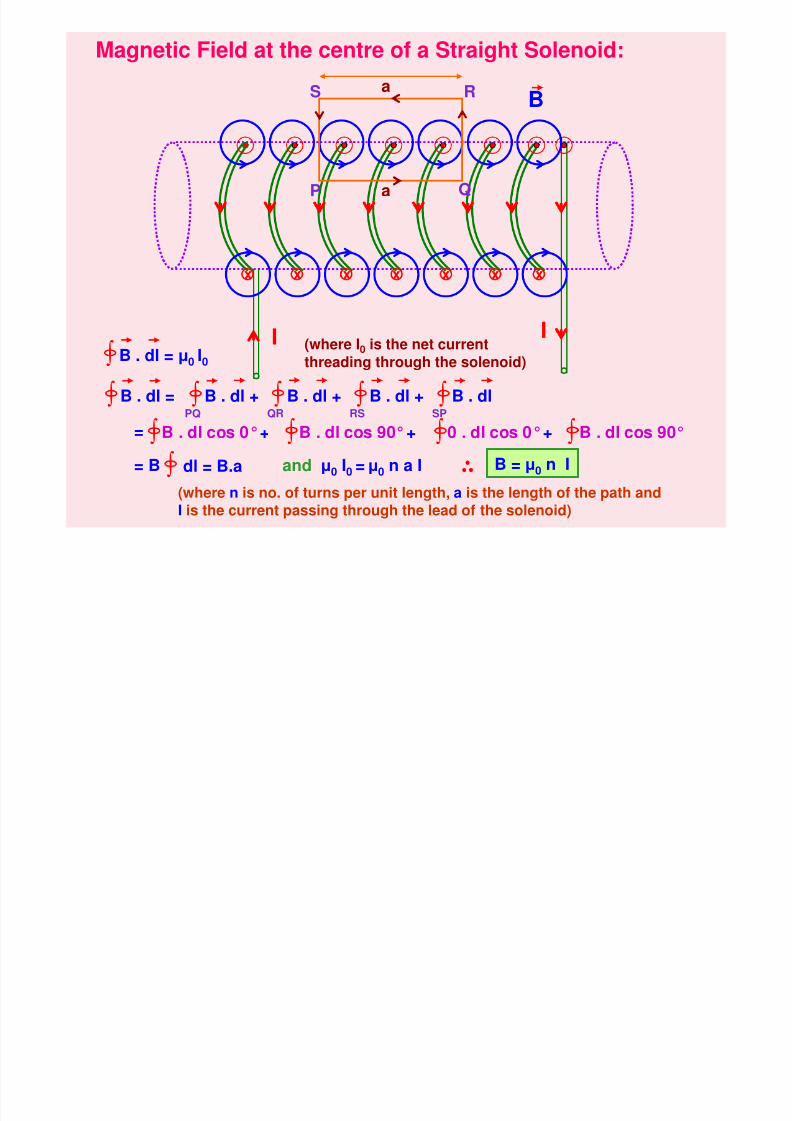
Magnetic Field at the centre of a Straight Solenoid:
I I
xxxxx xx
P Q
RS
∫ B . dl = µ0 I0(where I0 is the net currentthreading through the solenoid)
∫ B . dl = ∫ B . dl +PQ ∫ B . dl +QR ∫ B . dl +RS ∫ B . dlSP
B
B . dl cos 0°+∫ ∫ B . dl cos 90°+ ∫ 0 . dl cos 0°+ ∫ B . dl cos 90°=
= B ∫ dl = B.a and µ0 I0 = µ0 n a I
(where n is no. of turns per unit length, a is the length of the path andI is the current passing through the lead of the solenoid)
a
a
B = µ0 n I
M ti Fi ld d t T id l S l id (T id)
8/6/2019 3 Magnetic Effects of Current & Magnetism
http://slidepdf.com/reader/full/3-magnetic-effects-of-current-magnetism 33/54
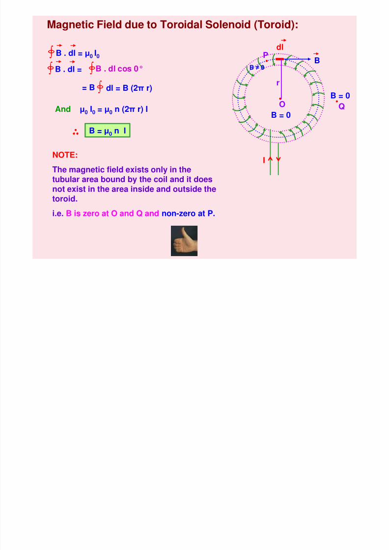
Magnetic Field due to Toroidal Solenoid (Toroid):
I
dl
BP
O QB = 0
B = 0
∫ B . dl = µ0 I0
B . dl cos 0°∫= B ∫ dl = B (2π r)
r
And µ0 I0 = µ0 n (2π r) I
B = µ0 n I
∫ B . dl =
NOTE:
The magnetic field exists only in thetubular area bound by the coil and it doesnot exist in the area inside and outside the
toroid.
i.e. B is zero at O and Q and non-zero at P.
B ≠ 0
8/6/2019 3 Magnetic Effects of Current & Magnetism
http://slidepdf.com/reader/full/3-magnetic-effects-of-current-magnetism 34/54
MAGNETISM
1. Bar Magnet and its properties2. Current Loop as a Magnetic Dipole and Dipole Moment
3. Current Solenoid equivalent to Bar Magnet
4. Bar Magnet and it Dipole Moment
5. Coulomb’s Law in Magnetism
6. Important Terms in Magnetism
7. Magnetic Field due to a Magnetic Dipole
8. Torque and Work Done on a Magnetic Dipole
9. Terrestrial Magnetism
10.Elements of Earth’s Magnetic Field
11.Tangent Law12.Properties of Dia-, Para- and Ferro-magnetic substances
13.Curie’s Law in Magnetism
14.Hysteresis in Magnetism
Magnetism:
8/6/2019 3 Magnetic Effects of Current & Magnetism
http://slidepdf.com/reader/full/3-magnetic-effects-of-current-magnetism 35/54
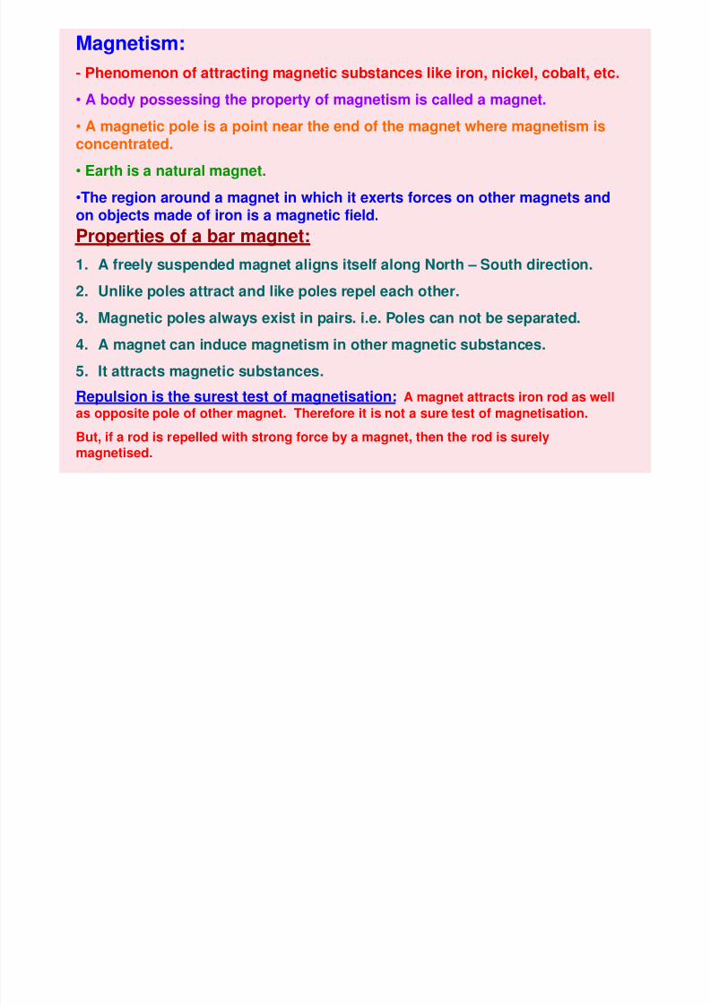
Magnetism:
- Phenomenon of attracting magnetic substances like iron, nickel, cobalt, etc.
• A body possessing the property of magnetism is called a magnet.
• A magnetic pole is a point near the end of the magnet where magnetism isconcentrated.
• Earth is a natural magnet.
•The region around a magnet in which it exerts forces on other magnets andon objects made of iron is a magnetic field.
Properties of a bar magnet:
1. A freely suspended magnet aligns itself along North – South direction.2. Unlike poles attract and like poles repel each other.
3. Magnetic poles always exist in pairs. i.e. Poles can not be separated.
4. A magnet can induce magnetism in other magnetic substances.
5. It attracts magnetic substances.
Repulsion is the surest test of magnetisation: A magnet attracts iron rod as wellas opposite pole of other magnet. Therefore it is not a sure test of magnetisation.
But, if a rod is repelled with strong force by a magnet, then the rod is surely
magnetised.
R t ti f U if M ti Fi ld
8/6/2019 3 Magnetic Effects of Current & Magnetism
http://slidepdf.com/reader/full/3-magnetic-effects-of-current-magnetism 36/54
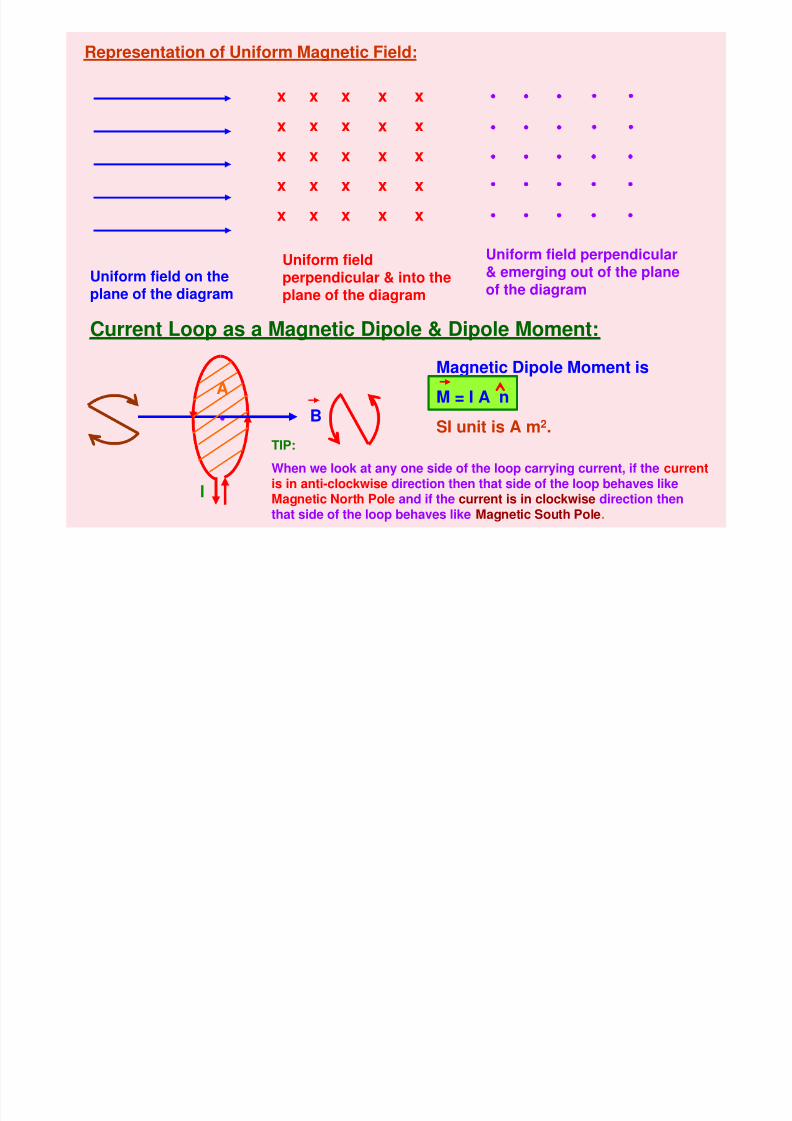
Representation of Uniform Magnetic Field:
x x x x x
x x x x x
x x x x x
x x x x x
x x x x x
Uniform field on theplane of the diagram
Uniform fieldperpendicular & into theplane of the diagram
Uniform field perpendicular& emerging out of the planeof the diagram
Current Loop as a Magnetic Dipole & Dipole Moment:
I
B
Magnetic Dipole Moment is
M = I A nSI unit is A m2.
A
TIP:
When we look at any one side of the loop carrying current, if the currentis in anti-clockwise direction then that side of the loop behaves like
Magnetic North Pole and if the current is in clockwise direction thenthat side of the loop behaves like Magnetic South Pole.
8/6/2019 3 Magnetic Effects of Current & Magnetism
http://slidepdf.com/reader/full/3-magnetic-effects-of-current-magnetism 37/54
B
I I
xxxxx xx
B
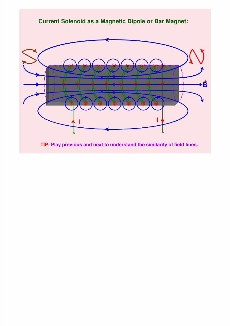
Current Solenoid as a Magnetic Dipole or Bar Magnet:
TIP: Play previous and next to understand the similarity of field lines.
Bar Magnet:
8/6/2019 3 Magnetic Effects of Current & Magnetism
http://slidepdf.com/reader/full/3-magnetic-effects-of-current-magnetism 38/54
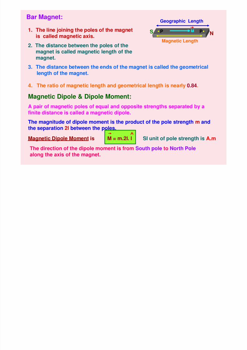
Bar Magnet:
S NP PMagnetic Length
Geographic Length
M1. The line joining the poles of the magnetis called magnetic axis.
2. The distance between the poles of themagnet is called magnetic length of themagnet.
Magnetic Dipole & Dipole Moment:
A pair of magnetic poles of equal and opposite strengths separated by afinite distance is called a magnetic dipole.
The magnitude of dipole moment is the product of the pole strength m andthe separation 2l between the poles.
3. The distance between the ends of the magnet is called the geometricallength of the magnet.
4. The ratio of magnetic length and geometrical length is nearly 0.84.
Magnetic Dipole Moment is M = m.2l. l
The direction of the dipole moment is from South pole to North Pole
along the axis of the magnet.
SI unit of pole strength is A.m
C l b’ L i M ti
8/6/2019 3 Magnetic Effects of Current & Magnetism
http://slidepdf.com/reader/full/3-magnetic-effects-of-current-magnetism 39/54
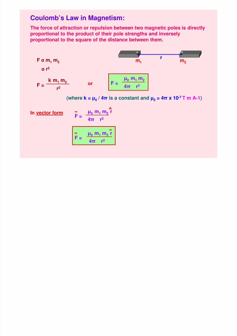
Coulomb’s Law in Magnetism:
The force of attraction or repulsion between two magnetic poles is directly
proportional to the product of their pole strengths and inverselyproportional to the square of the distance between them.
m1 m2
r
F α m1 m2
α r2
F =µ0 m1 m2
4π r2F =k m1 m2
r2or
(where k = µ0 / 4π is a constant and µ0 = 4π x 10-7 T m A-1)
In vector form µ0 m1 m2 rF =
4π r2
µ0 m1 m2 rF =
4π r3
M ti I t it M ti i f (H)
8/6/2019 3 Magnetic Effects of Current & Magnetism
http://slidepdf.com/reader/full/3-magnetic-effects-of-current-magnetism 40/54
Magnetic Intensity or Magnetising force (H):
i) Magnetic Intensity at a point is the force experienced by a north pole
of unit pole strength placed at that point due to pole strength of thegiven magnet. H = B / µ
ii) It is also defined as the magnetomotive force per unit length.
iii) It can also be defined as the degree or extent to which a magnetic
field can magnetise a substance.
iv) It can also be defined as the force experienced by a unit positivecharge flowing with unit velocity in a direction normal to themagnetic field.
v) Its SI unit is ampere-turns per linear metre.
vi) Its cgs unit is oersted.
Magnetic Field Strength or Magnetic Field or Magnetic Inductionor Magnetic Flux Density (B):
i) Magnetic Flux Density is the number of magnetic lines of forcepassing normally through a unit area of a substance. B = µ H
ii) Its SI unit is weber-m-2 or Tesla (T).
iii) Its cgs unit is gauss. 1 gauss = 10- 4
Tesla
Magnetic Flux (Φ):
8/6/2019 3 Magnetic Effects of Current & Magnetism
http://slidepdf.com/reader/full/3-magnetic-effects-of-current-magnetism 41/54
Relation between B and H:
B = µ H (where µ is the permeability of the medium)
Magnetic Permeability (µ):
It is the degree or extent to which magnetic lines of forcecan pass enter a substance.
Its SI unit is T m A-1 or wb A-1 m-1 or H m-1
g ( )
i) It is defined as the number of magnetic lines of forcepassing normally through a surface.
ii) Its SI unit is weber.
Relative Magnetic Permeability (µr):
It is the ratio of magnetic flux density in a material to that in vacuum.
It can also be defined as the ratio of absolute permeability of the materialto that in vacuum.
µr = B / B0 µr = µ / µ0or
Intensity of Magnetisation: (I):
8/6/2019 3 Magnetic Effects of Current & Magnetism
http://slidepdf.com/reader/full/3-magnetic-effects-of-current-magnetism 42/54
y g ( )
i) It is the degree to which a substance is magnetised when placed in amagnetic field.
ii) It can also be defined as the magnetic dipole moment (M) acquired perunit volume of the substance (V).
iii) It can also be defined as the pole strength (m) per unit cross-sectionalarea (A) of the substance.
iv) I = M / V
v) I = m(2l) / A(2l) = m / A
vi) SI unit of Intensity of Magnetisation is A m-1.
Magnetic Susceptibility (cm ):
i) It is the property of the substance which shows how easily a substancecan be magnetised.
ii) It can also be defined as the ratio of intensity of magnetisation (I) in asubstance to the magnetic intensity (H) applied to the substance.
iii) cm = I / H Susceptibility has no unit.
Relation between Magnetic Permeability (µr) & Susceptibility (cm ):
µr = 1 + cm
Magnetic Field due to a Magnetic Dipole (Bar Magnet):
8/6/2019 3 Magnetic Effects of Current & Magnetism
http://slidepdf.com/reader/full/3-magnetic-effects-of-current-magnetism 43/54
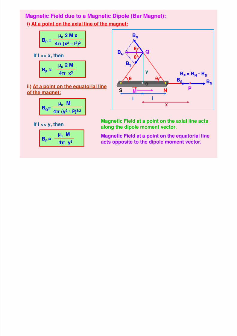
Magnetic Field due to a Magnetic Dipole (Bar Magnet):
i) At a point on the axial line of the magnet:
O
S Nll
x
BNBS
BS
BN
BQ
y
Qθ
θ
θθ
BQ=µ0 M
4π (y2 + l2)3/2
ii) At a point on the equatorial line
of the magnet:
BP =µ0 2 M x
4π (x2 – l2)2
If l << x, then
If l << y, then
BP ≈µ0 2 M
4π x3
BP ≈µ0 M
4π y3
P
BP = BN - BS
M
Magnetic Field at a point on the axial line actsalong the dipole moment vector.
Magnetic Field at a point on the equatorial lineacts opposite to the dipole moment vector.
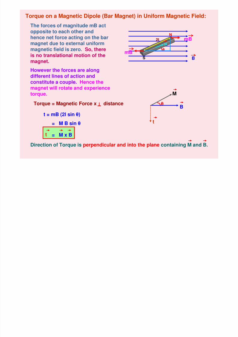
Torque on a Magnetic Dipole (Bar Magnet) in Uniform Magnetic Field:
8/6/2019 3 Magnetic Effects of Current & Magnetism
http://slidepdf.com/reader/full/3-magnetic-effects-of-current-magnetism 44/54
B
o que o a ag et c po e ( a ag et) U o ag et c e d
The forces of magnitude mB act
opposite to each other andhence net force acting on the barmagnet due to external uniformmagnetic field is zero. So, thereis no translational motion of the
magnet.
θ
However the forces are alongdifferent lines of action andconstitute a couple. Hence themagnet will rotate and experiencetorque.
t
B
M
Torque = Magnetic Force x distance
θ
2l
t = mB (2l sin θ)
= M B sin θ
t = M x B
Direction of Torque is perpendicular and into the plane containing M and B.
mB
mBM
N
S
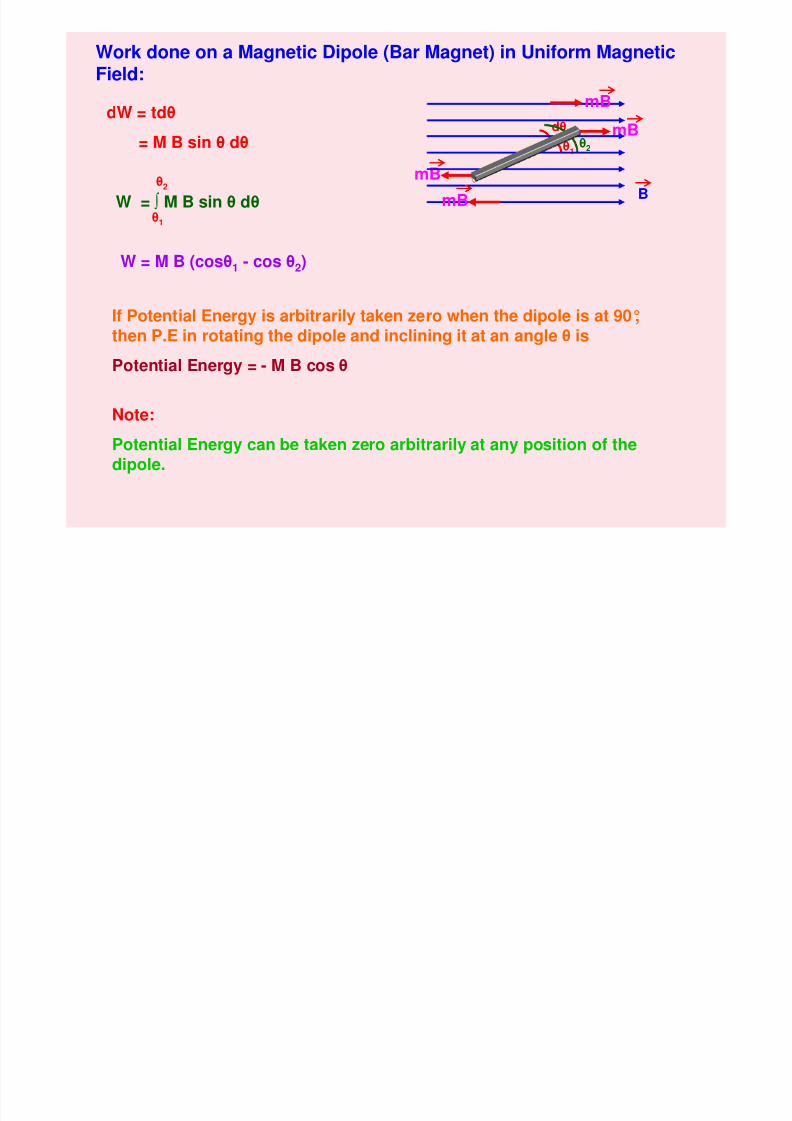
Work done on a Magnetic Dipole (Bar Magnet) in Uniform Magnetic
8/6/2019 3 Magnetic Effects of Current & Magnetism
http://slidepdf.com/reader/full/3-magnetic-effects-of-current-magnetism 45/54
g p ( g ) gField:
mB
mBdθ
θ1θ2
dW = tdθ
= M B sin θ dθ
W = ∫ M B sin θ dθ
W = M B (cosθ1 - cos θ2)
θ1
θ2
If Potential Energy is arbitrarily taken zero when the dipole is at 90°,then P.E in rotating the dipole and inclining it at an angle θ is
Potential Energy = - M B cos θ
B
mB
mB
Note:
Potential Energy can be taken zero arbitrarily at any position of thedipole.
Terrestrial Magnetism:
8/6/2019 3 Magnetic Effects of Current & Magnetism
http://slidepdf.com/reader/full/3-magnetic-effects-of-current-magnetism 46/54
Terrestrial Magnetism:
i) Geographic Axis is a straight line passing through thegeographical poles of the earth. It is the axis of rotation of theearth. It is also known as polar axis.
ii) Geographic Meridian at any place is a vertical plane passingthrough the geographic north and south poles of the earth.
iii) Geographic Equator is a great circle on the surface of the earth, ina plane perpendicular to the geographic axis. All the points on thegeographic equator are at equal distances from the geographicpoles.
iv) Magnetic Axis is a straight line passing through the magneticpoles of the earth. It is inclined to Geographic Axis nearly at anangle of 17°.
v) Magnetic Meridian at any place is a vertical plane passing through
the magnetic north and south poles of the earth.vi) Magnetic Equator is a great circle on the surface of the earth, in a
plane perpendicular to the magnetic axis. All the points on themagnetic equator are at equal distances from the magnetic poles.
Declination (θ):
Geographic
8/6/2019 3 Magnetic Effects of Current & Magnetism
http://slidepdf.com/reader/full/3-magnetic-effects-of-current-magnetism 47/54
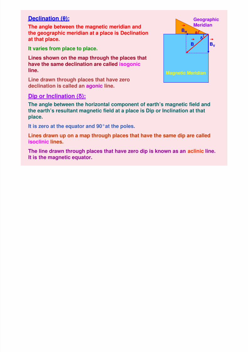
Declination (θ):
θ δ
BV
BH
B
Magnetic Meridian
GeographicMeridianThe angle between the magnetic meridian and
the geographic meridian at a place is Declinationat that place.
It varies from place to place.
Lines shown on the map through the places that
have the same declination are called isogonicline.
Line drawn through places that have zerodeclination is called an agonic line.
Dip or Inclination (δ):The angle between the horizontal component of earth’s magnetic field andthe earth’s resultant magnetic field at a place is Dip or Inclination at thatplace.
It is zero at the equator and 90°at the poles.Lines drawn up on a map through places that have the same dip are calledisoclinic lines.
The line drawn through places that have zero dip is known as an aclinic line.
It is the magnetic equator.
Horizontal Component of Earth’s Magnetic Field (BH ):
8/6/2019 3 Magnetic Effects of Current & Magnetism
http://slidepdf.com/reader/full/3-magnetic-effects-of-current-magnetism 48/54
N
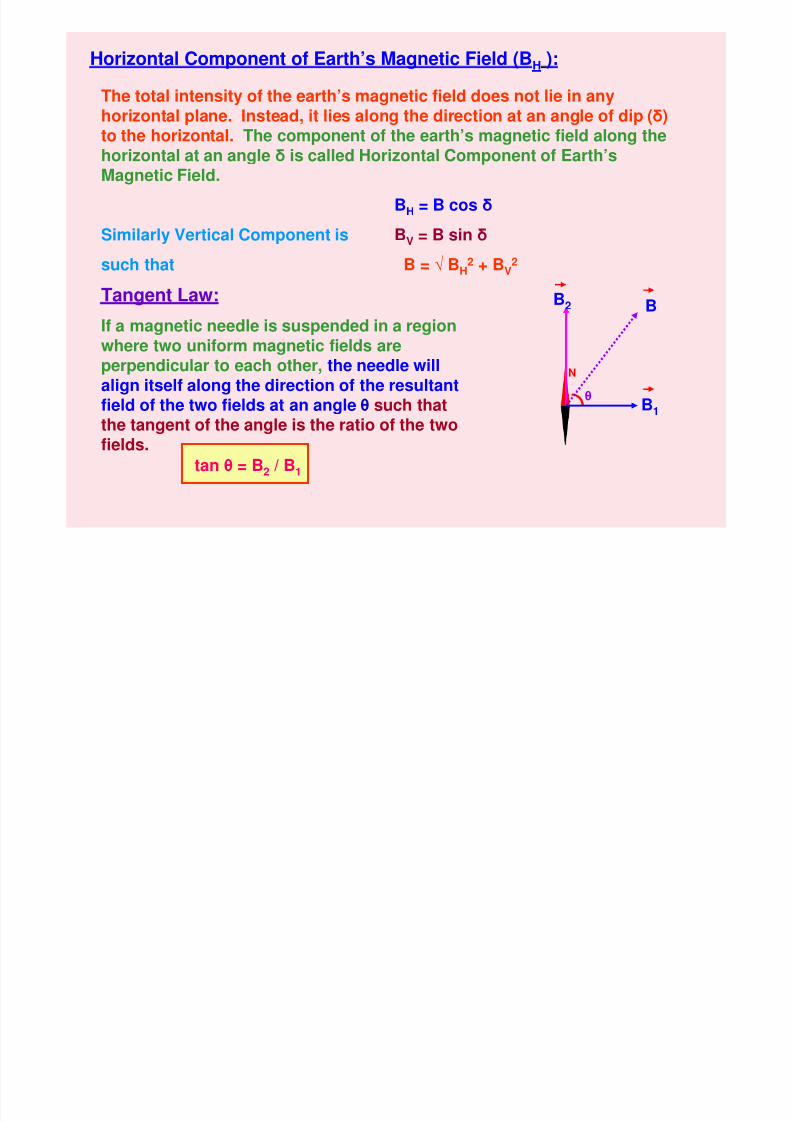
o o ta Co po e t o a t s ag et c e d ( H )
The total intensity of the earth’s magnetic field does not lie in any
horizontal plane. Instead, it lies along the direction at an angle of dip (δ)to the horizontal. The component of the earth’s magnetic field along thehorizontal at an angle δ is called Horizontal Component of Earth’sMagnetic Field.
BH = B cos δSimilarly Vertical Component is BV = B sin δ
such that B = √ BH2 + BV
2
Tangent Law:
If a magnetic needle is suspended in a regionwhere two uniform magnetic fields areperpendicular to each other, the needle willalign itself along the direction of the resultant
field of the two fields at an angle θ such thatthe tangent of the angle is the ratio of the twofields.
θ
B2 B
B1
tan θ = B2 / B1
Comparison of Dia, Para and Ferro Magnetic materials:
8/6/2019 3 Magnetic Effects of Current & Magnetism
http://slidepdf.com/reader/full/3-magnetic-effects-of-current-magnetism 49/54
p , g
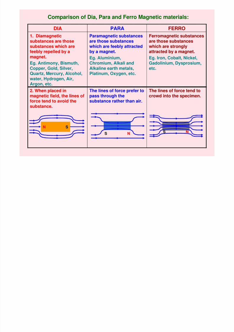
Ferromagnetic substancesare those substanceswhich are stronglyattracted by a magnet.
Eg. Iron, Cobalt, Nickel,
Gadolinium, Dysprosium,etc.
Paramagnetic substancesare those substanceswhich are feebly attractedby a magnet.
Eg. Aluminium,
Chromium, Alkali andAlkaline earth metals,Platinum, Oxygen, etc.
1. Diamagneticsubstances are thosesubstances which arefeebly repelled by amagnet.
Eg. Antimony, Bismuth,Copper, Gold, Silver,Quartz, Mercury, Alcohol,water, Hydrogen, Air,Argon, etc.
FERROPARADIA
The lines of force tend tocrowd into the specimen.
The lines of force prefer topass through thesubstance rather than air.
2. When placed inmagnetic field, the lines offorce tend to avoid thesubstance.
N S
S N S N
8/6/2019 3 Magnetic Effects of Current & Magnetism
http://slidepdf.com/reader/full/3-magnetic-effects-of-current-magnetism 50/54
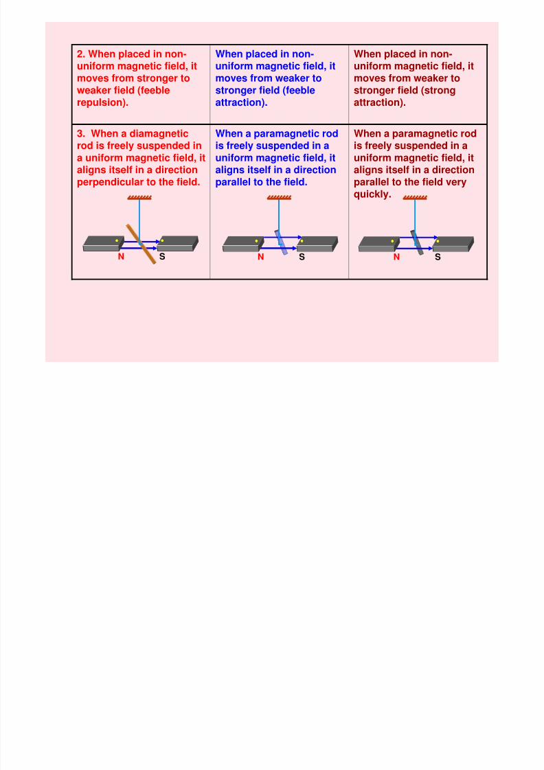
When a paramagnetic rod
is freely suspended in auniform magnetic field, italigns itself in a directionparallel to the field veryquickly.
When a paramagnetic rod
is freely suspended in auniform magnetic field, italigns itself in a directionparallel to the field.
3. When a diamagnetic
rod is freely suspended ina uniform magnetic field, italigns itself in a directionperpendicular to the field.
When placed in non-uniform magnetic field, it
moves from weaker tostronger field (strongattraction).
When placed in non-uniform magnetic field, it
moves from weaker tostronger field (feebleattraction).
2. When placed in non-uniform magnetic field, it
moves from stronger toweaker field (feeblerepulsion).
SN SN SN
8/6/2019 3 Magnetic Effects of Current & Magnetism
http://slidepdf.com/reader/full/3-magnetic-effects-of-current-magnetism 51/54
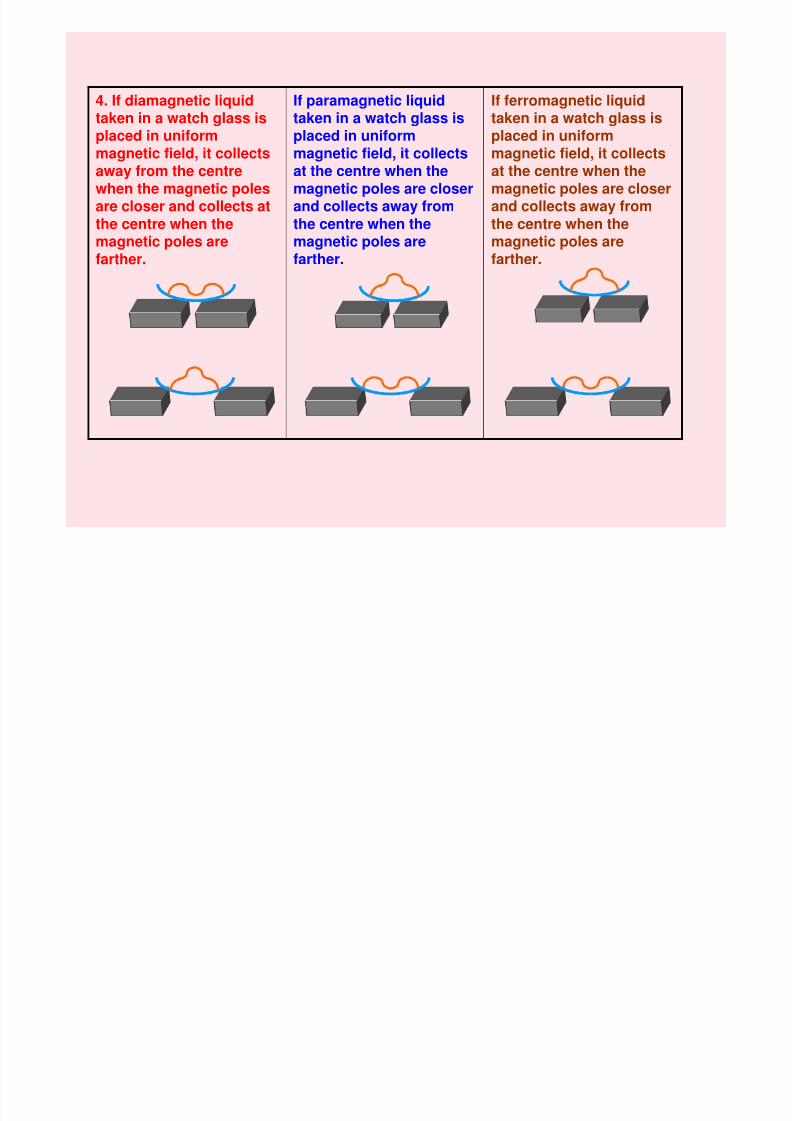
If ferromagnetic liquidtaken in a watch glass isplaced in uniformmagnetic field, it collectsat the centre when themagnetic poles are closer
and collects away fromthe centre when themagnetic poles arefarther.
If paramagnetic liquidtaken in a watch glass isplaced in uniformmagnetic field, it collectsat the centre when themagnetic poles are closer
and collects away fromthe centre when themagnetic poles arefarther.
4. If diamagnetic liquidtaken in a watch glass isplaced in uniformmagnetic field, it collectsaway from the centrewhen the magnetic poles
are closer and collects atthe centre when themagnetic poles arefarther.
When a ferromagneticWhen a paramagnetic5 When a diamagnetic
8/6/2019 3 Magnetic Effects of Current & Magnetism
http://slidepdf.com/reader/full/3-magnetic-effects-of-current-magnetism 52/54
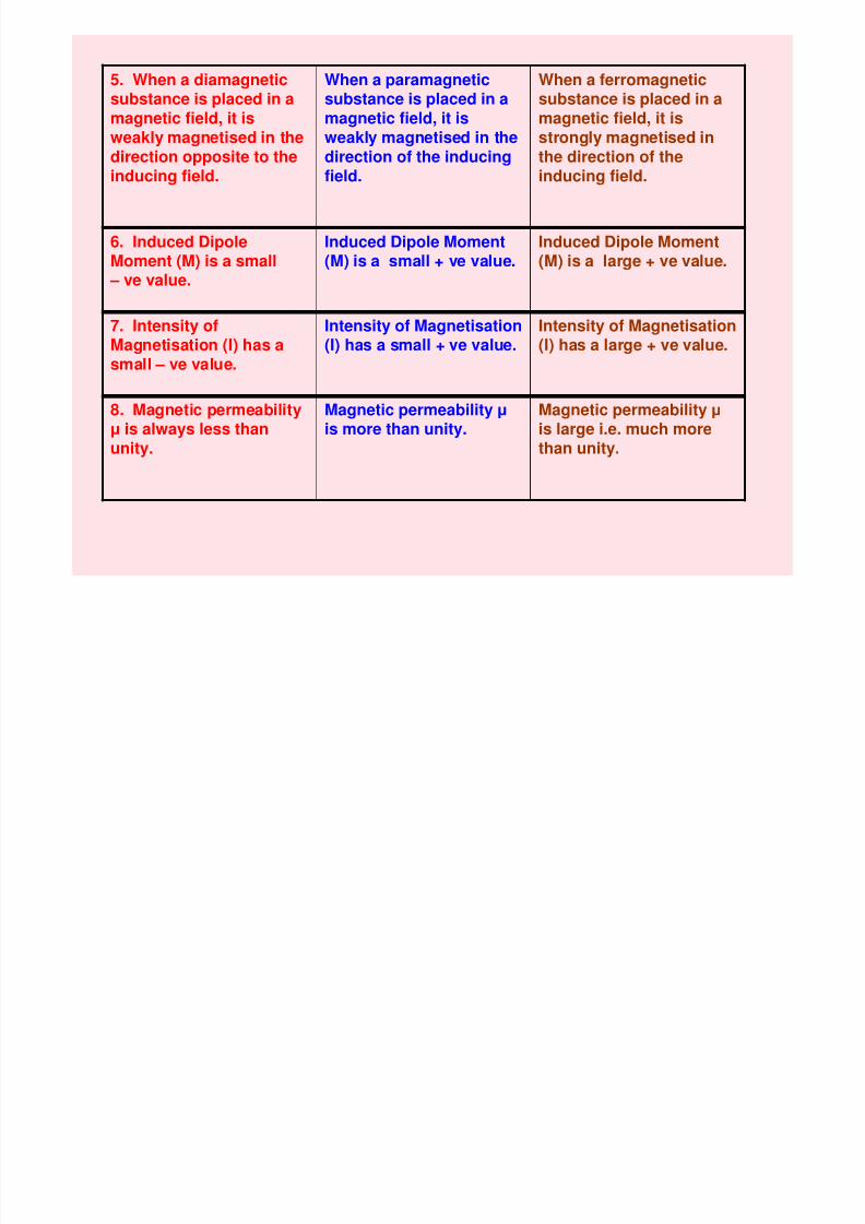
When a ferromagneticsubstance is placed in a
magnetic field, it isstrongly magnetised inthe direction of theinducing field.
When a paramagneticsubstance is placed in a
magnetic field, it isweakly magnetised in thedirection of the inducingfield.
5. When a diamagneticsubstance is placed in a
magnetic field, it isweakly magnetised in thedirection opposite to theinducing field.
Induced Dipole Moment(M) is a large + ve value.
Induced Dipole Moment(M) is a small + ve value.
6. Induced DipoleMoment (M) is a small
– ve value.
Magnetic permeability µis large i.e. much more
than unity.
Magnetic permeability µis more than unity.
8. Magnetic permeabilityµ is always less than
unity.
7. Intensity ofMagnetisation (I) has asmall – ve value.
Intensity of Magnetisation(I) has a small + ve value.
Intensity of Magnetisation(I) has a large + ve value.
9. Magnetic susceptibility
8/6/2019 3 Magnetic Effects of Current & Magnetism
http://slidepdf.com/reader/full/3-magnetic-effects-of-current-magnetism 53/54
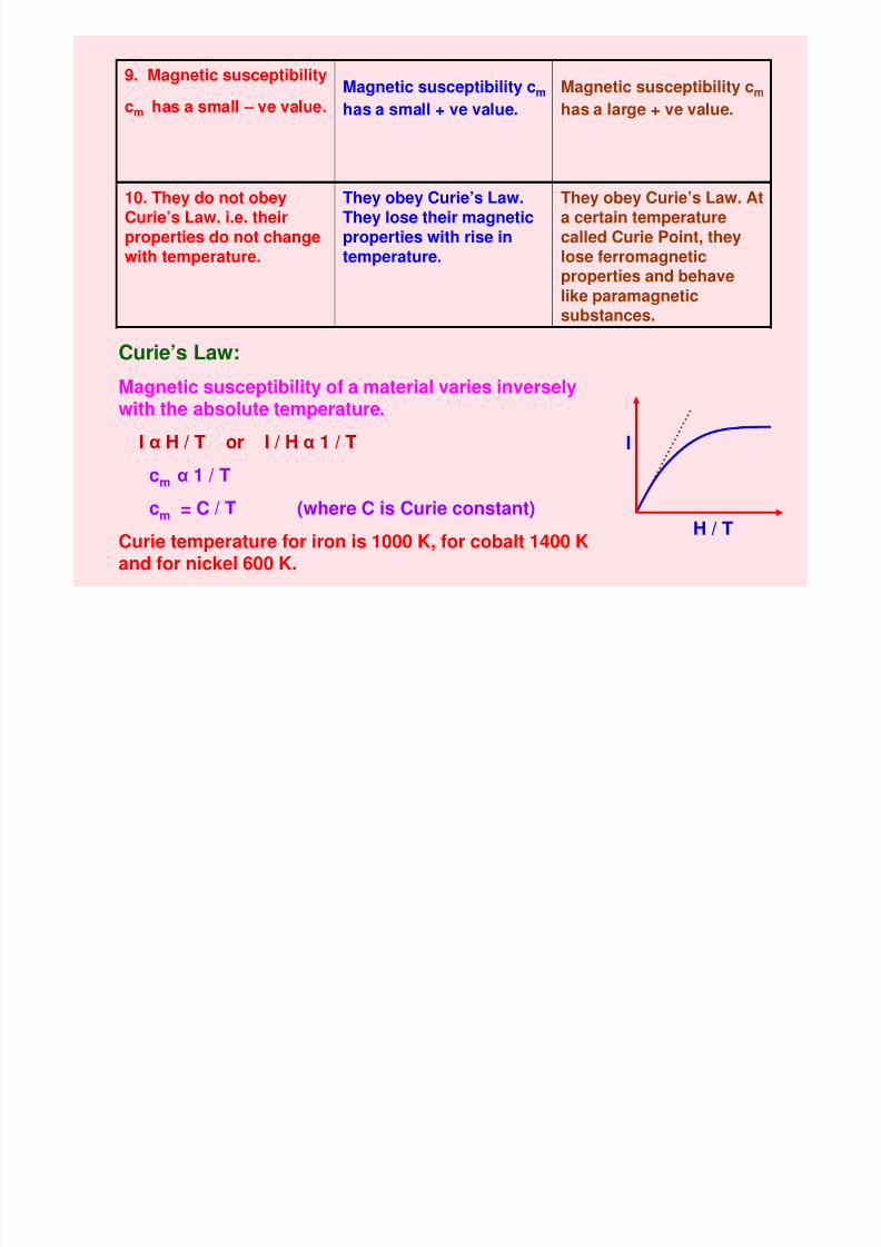
Magnetic susceptibility cm
has a large + ve value.
Magnetic susceptibility cm
has a small + ve value.
9. Magnetic susceptibility
cm has a small – ve value.
They obey Curie’s Law. Ata certain temperature
called Curie Point, theylose ferromagneticproperties and behavelike paramagneticsubstances.
They obey Curie’s Law.They lose their magnetic
properties with rise intemperature.
10. They do not obeyCurie’s Law. i.e. their
properties do not changewith temperature.
Curie’s Law:
Magnetic susceptibility of a material varies inverselywith the absolute temperature.
Iα
H / T or I / Hα
1 / Tcm α 1 / T
cm = C / T (where C is Curie constant)
Curie temperature for iron is 1000 K, for cobalt 1400 K
and for nickel 600 K.
I
H / T
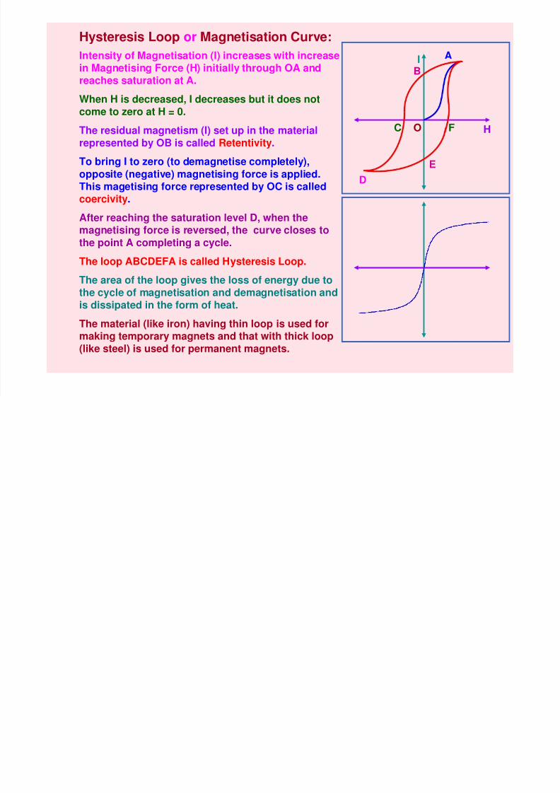
Hysteresis Loop or Magnetisation Curve:
AI t it f M ti ti (I) i ith i
8/6/2019 3 Magnetic Effects of Current & Magnetism
http://slidepdf.com/reader/full/3-magnetic-effects-of-current-magnetism 54/54
I
HO
A
B
C
D
E
F
Intensity of Magnetisation (I) increases with increasein Magnetising Force (H) initially through OA and
reaches saturation at A.
When H is decreased, I decreases but it does notcome to zero at H = 0.
The residual magnetism (I) set up in the material
represented by OB is called Retentivity.To bring I to zero (to demagnetise completely),opposite (negative) magnetising force is applied.This magetising force represented by OC is calledcoercivity.
After reaching the saturation level D, when themagnetising force is reversed, the curve closes tothe point A completing a cycle.
The loop ABCDEFA is called Hysteresis Loop.
The area of the loop gives the loss of energy due tothe cycle of magnetisation and demagnetisation andis dissipated in the form of heat.
The material (like iron) having thin loop is used formaking temporary magnets and that with thick loop(like steel) is used for permanent magnets.


![1 L 27 Electricity & Magnetism [5] Magnets –permanent magnets –Electromagnets –The Earth’s magnetic field magnetic forces applications Magnetism](https://img.dokumen.tips/doc/110x75/56649d9c5503460f94a85bd1/1-l-27-electricity-magnetism-5-magnets-permanent-magnets-electromagnets.jpg)