Embed Size (px)
Citation preview

Electricity and MagnetismMagnetic Fields
Lana Sheridan
De Anza College
Nov 3, 2015
Overview
• magnets
• magnetic field
• Earth’s magnetic field
• magnetic force on a charge

Magnets
Like charges, magnets also interact at a distance.
They can either attract or repel.
Similarly to charges, they can also attract certain kinds of nearbymaterial (eg. iron) by magnetizing it. (cf. polarization)

Magnets and Magnetic fields
Compass needles point along the direction of a magnetic field.
29.1 Analysis Model: Particle in a Field (Magnetic) 869
The poles received their names because of the way a magnet, such as that in a compass, behaves in the presence of the Earth’s magnetic field. If a bar magnet is suspended from its midpoint and can swing freely in a horizontal plane, it will rotate until its north pole points to the Earth’s geographic North Pole and its south pole points to the Earth’s geographic South Pole.1
In 1600, William Gilbert (1540–1603) extended de Maricourt’s experiments to a variety of materials. He knew that a compass needle orients in preferred directions, so he suggested that the Earth itself is a large, permanent magnet. In 1750, experimenters used a torsion balance to show that magnetic poles exert attractive or repulsive forces on each other and that these forces vary as the inverse square of the distance between interacting poles. Although the force between two magnetic poles is otherwise similar to the force between two electric charges, electric charges can be isolated (witness the electron and proton), whereas a single magnetic pole has never been isolated. That is, magnetic poles are always found in pairs. All attempts thus far to detect an isolated magnetic pole have been unsuc-cessful. No matter how many times a permanent magnet is cut in two, each piece always has a north and a south pole.2
The relationship between magnetism and electricity was discovered in 1819 when, during a lecture demonstration, Hans Christian Oersted found that an electric current in a wire deflected a nearby compass needle.3 In the 1820s, further connections between electricity and magnetism were demonstrated independently by Faraday and Joseph Henry (1797–1878). They showed that an electric current can be produced in a circuit either by moving a magnet near the circuit or by changing the current in a nearby circuit. These observations demonstrate that a changing magnetic field creates an electric field. Years later, theoretical work by Max-well showed that the reverse is also true: a changing electric field creates a magnetic field. This chapter examines the forces that act on moving charges and on current-carrying wires in the presence of a magnetic field. The source of the magnetic field is described in Chapter 30.
29.1 Analysis Model: Particle in a Field (Magnetic)In our study of electricity, we described the interactions between charged objects in terms of electric fields. Recall that an electric field surrounds any electric charge. In addition to containing an electric field, the region of space surrounding any moving electric charge also contains a magnetic field. A magnetic field also sur-rounds a magnetic substance making up a permanent magnet. Historically, the symbol B
S has been used to represent a magnetic field, and we
use this notation in this book. The direction of the magnetic field BS
at any location is the direction in which a compass needle points at that location. As with the elec-tric field, we can represent the magnetic field by means of drawings with magnetic field lines. Figure 29.1 shows how the magnetic field lines of a bar magnet can be traced with the aid of a compass. Notice that the magnetic field lines outside the magnet
1The Earth’s geographic North Pole is magnetically a south pole, whereas the Earth’s geographic South Pole is mag-netically a north pole. Because opposite magnetic poles attract each other, the pole on a magnet that is attracted to the Earth’s geographic North Pole is the magnet’s north pole and the pole attracted to the Earth’s geographic South Pole is the magnet’s south pole.2There is some theoretical basis for speculating that magnetic monopoles—isolated north or south poles—may exist in nature, and attempts to detect them are an active experimental field of investigation.3The same discovery was reported in 1802 by an Italian jurist, Gian Domenico Romagnosi, but was overlooked, prob-ably because it was published in an obscure journal.
Hans Christian OerstedDanish Physicist and Chemist (1777–1851)Oersted is best known for observing that a compass needle deflects when placed near a wire carrying a current. This important discovery was the first evidence of the connection between electric and magnetic phenomena. Oersted was also the first to prepare pure aluminum.
© N
orth
Win
d/N
orth
Win
d Pi
ctur
e Ar
chiv
es --
Al
l rig
hts r
eser
ved.
N S
Figure 29.1 Compass needles can be used to trace the magnetic field lines in the region outside a bar magnet.
1Figure from Serway and Jewett, 9th ed.

Magnetic Field LinesDraw magnetic field lines similarly to E -field line: lines emergefrom North pole, enter South pole, denser lines means a strongerfield.
A bar magnet:
738 CHAPTE R 28 MAG N ETIC F I E LDS
HALLIDAY REVISED
An earlier (non-SI) unit for , still in common use, is the gauss (G), and
1 tesla ! 104 gauss. (28-5)
Table 28-1 lists the magnetic fields that occur in a few situations. Note that Earth’smagnetic field near the planet’s surface is about 10"4 T (! 100 mT or 1 G).
B:
Table 28-1
Some Approximate Magnetic Fields
At surface of neutron star 108 TNear big electromagnet 1.5 TNear small bar magnet 10"2 TAt Earth’s surface 10"4 TIn interstellar space 10"10 TSmallest value in
magnetically shielded room 10"14 T
Fig. 28-4 (a) The magnetic fieldlines for a bar magnet. (b) A “cowmagnet”—a bar magnet that is in-tended to be slipped down into the ru-men of a cow to prevent accidentallyingested bits of scrap iron from reach-ing the cow’s intestines.The iron filingsat its ends reveal the magnetic fieldlines. (Courtesy Dr. Richard Cannon,Southeast Missouri State University,Cape Girardeau)
N
S
(a)
(b)
Opposite magnetic poles attract each other, and like magnetic poles repel each other.
Magnetic Field LinesWe can represent magnetic fields with field lines, as we did for electric fields.Similar rules apply: (1) the direction of the tangent to a magnetic field line atany point gives the direction of at that point, and (2) the spacing of the linesrepresents the magnitude of —the magnetic field is stronger where the linesare closer together, and conversely.
Figure 28-4a shows how the magnetic field near a bar magnet (a permanentmagnet in the shape of a bar) can be represented by magnetic field lines.The linesall pass through the magnet, and they all form closed loops (even those thatare not shown closed in the figure).The external magnetic effects of a bar magnetare strongest near its ends, where the field lines are most closely spaced.Thus, themagnetic field of the bar magnet in Fig. 28-4b collects the iron filings mainly nearthe two ends of the magnet.
The (closed) field lines enter one end of a magnet and exit the other end. Theend of a magnet from which the field lines emerge is called the north pole of themagnet; the other end, where field lines enter the magnet, is called the south pole.Because a magnet has two poles, it is said to be a magnetic dipole. The magnets weuse to fix notes on refrigerators are short bar magnets. Figure 28-5 shows two othercommon shapes for magnets: a horseshoe magnet and a magnet that has been bentaround into the shape of a C so that the pole faces are facing each other. (The mag-netic field between the pole faces can then be approximately uniform.) Regardlessof the shape of the magnets, if we place two of them near each other we find:
B:
B:
CHECKPOINT 1
The figure shows threesituations in which acharged particle with ve-locity travels througha uniform magnetic field
. In each situation,what is the direction ofthe magnetic force on the particle?
F:
B
B:
v: +
y
x
z
y
x
z
y
x
z
(a) (b) (c)
B
B B
v v
v
Earth has a magnetic field that is produced in its core by still unknownmechanisms. On Earth’s surface, we can detect this magnetic field with a compass,which is essentially a slender bar magnet on a low-friction pivot.This bar magnet,or this needle, turns because its north-pole end is attracted toward the Arcticregion of Earth. Thus, the south pole of Earth’s magnetic field must be locatedtoward the Arctic. Logically, we then should call the pole there a south pole.However, because we call that direction north, we are trapped into the statementthat Earth has a geomagnetic north pole in that direction.
With more careful measurement we would find that in the Northern Hemi-sphere, the magnetic field lines of Earth generally point down into Earth and towardthe Arctic. In the Southern Hemisphere, they generally point up out of Earth andaway from the Antarctic—that is, away from Earth’s geomagnetic south pole.
halliday_c28_735-763v2.qxd 27-11-2009 16:19 Page 738
1Figure from Halliday, Resnick, Walker, 9th ed.

Magnetic Field Lines
Magnetic fields for a horseshoe magnet and a C-shape magnet: 73928-3 TH E DE FI N ITION OF BPART 3
HALLIDAY REVISED
Fig. 28-5 (a) A horseshoe magnet and (b) a C-shaped magnet. (Only some of theexternal field lines are shown.)
N S
S
N
(a) (b)
The field lines run fromthe north pole to thesouth pole.
Sample Problem
Direction: To find the direction of , we use the fact that has the direction of the cross product Because thecharge q is positive, must have the same direction as which can be determined with the right-hand rule for crossproducts (as in Fig. 28-2d).We know that is directed horizon-tally from south to north and is directed vertically up. Theright-hand rule shows us that the deflecting force must be directed horizontally from west to east, as Fig. 28-6 shows. (Thearray of dots in the figure represents a magnetic field directedout of the plane of the figure.An array of Xs would have repre-sented a magnetic field directed into that plane.)
If the charge of the particle were negative, the magneticdeflecting force would be directed in the opposite direction—that is, horizontally from east to west. This is predicted auto-matically by Eq. 28-2 if we substitute a negative value for q.
F:
B
B:
v:
! B:
,v:F:
B
! B:
.qv:F:
BF:
B
a !FB
m!
6.1 " 10#15 N1.67 " 10#27 kg
! 3.7 " 1012 m/s2.
Magnetic force on a moving charged particle
A uniform magnetic field , with magnitude 1.2 mT, isdirected vertically upward throughout the volume of a labo-ratory chamber. A proton with kinetic energy 5.3 MeV en-ters the chamber, moving horizontally from south to north.What magnetic deflecting force acts on the proton as it en-ters the chamber? The proton mass is 1.67 " 10#27 kg.(Neglect Earth’s magnetic field.)
Because the proton is charged and moving through a mag-netic field, a magnetic force can act on it. Because the ini-tial direction of the proton’s velocity is not along a magneticfield line, is not simply zero.
Magnitude: To find the magnitude of , we can use Eq. 28-3provided we first find the proton’s speed v.
We can find v from the given kinetic energy because. Solving for v, we obtain
Equation 28-3 then yields
(Answer)
This may seem like a small force, but it acts on a particle ofsmall mass, producing a large acceleration; namely,
! 6.1 " 10#15 N." (1.2 " 10#3 T)(sin 90$)
! (1.60 " 10#19 C)(3.2 " 107 m/s)FB ! |q|vB sin %
! 3.2 " 107 m/s.
v ! A 2Km
! A (2)(5.3 MeV)(1.60 " 10#13 J/MeV)1.67 " 10#27 kg
K ! 12 mv2
(FB ! |q|vB sin %)F:
B
F:
B
F:
B
B:
KEY I DEAS
Additional examples, video, and practice available at WileyPLUS
FB
N
S
EW
Path of proton
+
vB
Fig. 28-6 An overhead view of a proton moving from south tonorth with velocity in a chamber. A magnetic field is directedvertically upward in the chamber, as represented by the array ofdots (which resemble the tips of arrows).The proton is deflectedtoward the east.
v:
!"
halliday_c28_735-763v2.qxd 27-11-2009 16:19 Page 739
1Figure from Halliday, Resnick, Walker, 9th ed.

Magnetic Field Lines
Opposite poles attract each other:
1Figure from Wikipedia.
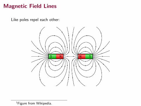
Magnetic Field Lines
Like poles repel each other:
1Figure from Wikipedia.
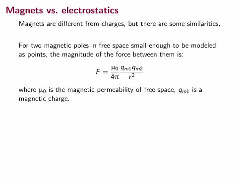
Magnets vs. electrostatics
Magnets are different from charges, but there are some similarities.
For two magnetic poles in free space small enough to be modeledas points, the magnitude of the force between them is:
F =µ0
4π
qm1qm2
r2
where µ0 is the magnetic permeability of free space, qm1 is amagnetic charge.
This looks a lot like the Coulomb force:
F =1
4πε0
q1q2r2
However, the equation for magnetic force is not in the textbook.Why?

Magnets vs. electrostatics
Magnets also have an important difference from electric charges.
It is possible for a positive or negative electric charge to be foundon its own: eg. electrons, protons.
Magnetic charges (qm) are never found on their own.
Magnets have a North pole and a South pole. If you break amagnet in two, new North and South poles form:
1Figure from Wikipedia.

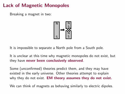
Lack of Magnetic Monopoles
Breaking a magnet in two:
It is impossible to separate a North pole from a South pole.
It is unclear at this time why magnetic monopoles do not exist, butthey have never been conclusively observed.
Some (unconfirmed) theories predict them, and they may haveexisted in the early universe. Other theories attempt to explainwhy they do not exist. EM theory assumes they do not exist.
We can think of magnets as behaving similarly to electric dipoles.

Electric dipoles vs. bar magnets
Magnetic field around barmagnet:
738 CHAPTE R 28 MAG N ETIC F I E LDS
HALLIDAY REVISED
An earlier (non-SI) unit for , still in common use, is the gauss (G), and
1 tesla ! 104 gauss. (28-5)
Table 28-1 lists the magnetic fields that occur in a few situations. Note that Earth’smagnetic field near the planet’s surface is about 10"4 T (! 100 mT or 1 G).
B:
Table 28-1
Some Approximate Magnetic Fields
At surface of neutron star 108 TNear big electromagnet 1.5 TNear small bar magnet 10"2 TAt Earth’s surface 10"4 TIn interstellar space 10"10 TSmallest value in
magnetically shielded room 10"14 T
Fig. 28-4 (a) The magnetic fieldlines for a bar magnet. (b) A “cowmagnet”—a bar magnet that is in-tended to be slipped down into the ru-men of a cow to prevent accidentallyingested bits of scrap iron from reach-ing the cow’s intestines.The iron filingsat its ends reveal the magnetic fieldlines. (Courtesy Dr. Richard Cannon,Southeast Missouri State University,Cape Girardeau)
N
S
(a)
(b)
Opposite magnetic poles attract each other, and like magnetic poles repel each other.
Magnetic Field LinesWe can represent magnetic fields with field lines, as we did for electric fields.Similar rules apply: (1) the direction of the tangent to a magnetic field line atany point gives the direction of at that point, and (2) the spacing of the linesrepresents the magnitude of —the magnetic field is stronger where the linesare closer together, and conversely.
Figure 28-4a shows how the magnetic field near a bar magnet (a permanentmagnet in the shape of a bar) can be represented by magnetic field lines.The linesall pass through the magnet, and they all form closed loops (even those thatare not shown closed in the figure).The external magnetic effects of a bar magnetare strongest near its ends, where the field lines are most closely spaced.Thus, themagnetic field of the bar magnet in Fig. 28-4b collects the iron filings mainly nearthe two ends of the magnet.
The (closed) field lines enter one end of a magnet and exit the other end. Theend of a magnet from which the field lines emerge is called the north pole of themagnet; the other end, where field lines enter the magnet, is called the south pole.Because a magnet has two poles, it is said to be a magnetic dipole. The magnets weuse to fix notes on refrigerators are short bar magnets. Figure 28-5 shows two othercommon shapes for magnets: a horseshoe magnet and a magnet that has been bentaround into the shape of a C so that the pole faces are facing each other. (The mag-netic field between the pole faces can then be approximately uniform.) Regardlessof the shape of the magnets, if we place two of them near each other we find:
B:
B:
CHECKPOINT 1
The figure shows threesituations in which acharged particle with ve-locity travels througha uniform magnetic field
. In each situation,what is the direction ofthe magnetic force on the particle?
F:
B
B:
v: +
y
x
z
y
x
z
y
x
z
(a) (b) (c)
B
B B
v v
v
Earth has a magnetic field that is produced in its core by still unknownmechanisms. On Earth’s surface, we can detect this magnetic field with a compass,which is essentially a slender bar magnet on a low-friction pivot.This bar magnet,or this needle, turns because its north-pole end is attracted toward the Arcticregion of Earth. Thus, the south pole of Earth’s magnetic field must be locatedtoward the Arctic. Logically, we then should call the pole there a south pole.However, because we call that direction north, we are trapped into the statementthat Earth has a geomagnetic north pole in that direction.
With more careful measurement we would find that in the Northern Hemi-sphere, the magnetic field lines of Earth generally point down into Earth and towardthe Arctic. In the Southern Hemisphere, they generally point up out of Earth andaway from the Antarctic—that is, away from Earth’s geomagnetic south pole.
halliday_c28_735-763v2.qxd 27-11-2009 16:19 Page 738
Electric field around a dipole:
25.4 O
btaining the Value of the Electric Field from the Electric Potential
755
25.4 Obtaining the Value of the Electric Field
from the Electric Potential
The electric field E S
and the electric potential V are related as shown in E
quation 25.3, w
hich tells us how to find DV if the electric field E S
is known. W
hat if the situ-ation is reversed? H
ow do w
e calculate the value of the electric field if the electric potential is know
n in a certain region?
From E
quation 25.3, the potential difference dV between tw
o points a distance ds apart can be expressed as
dV
52
E S?d
s S
(25.15)
If the electric field has only one component E
x , then E S?d
s S5
Ex dx. T
herefore, E
quation 25.15 becomes dV 5
2E
x dx, or
E
x5
2dVdx
(25.16)
That is, the x com
ponent of the electric field is equal to the negative of the deriv-ative of the electric potential w
ith respect to x. Similar statem
ents can be made
about the y and z components. E
quation 25.16 is the mathem
atical statement of
the electric field being a measure of the rate of change w
ith position of the electric potential as m
entioned in Section 25.1.
Experim
entally, electric potential and position can be measured easily w
ith a voltm
eter (a device for measuring potential difference) and a m
eterstick. Conse-
quently, an electric field can be determined by m
easuring the electric potential at several positions in the field and m
aking a graph of the results. According to E
qua-tion 25.16, the slope of a graph of V versus x at a given point provides the m
agnitude of the electric field at that point.
Imagine starting at a point and then m
oving through a displacement d
s S along
an equipotential surface. For this motion, dV 5
0 because the potential is constant along an equipotential surface. From
Equation 25.15, w
e see that dV5
2E S
?ds S
5 0;
therefore, because the dot product is zero, E S m
ust be perpendicular to the displace-m
ent along the equipotential surface. This result show
s that the equipotential sur-faces m
ust always be perpendicular to the electric field lines passing through them
.
As m
entioned at the end of Section 25.2, the equipotential surfaces associated w
ith a uniform electric field consist of a fam
ily of planes perpendicular to the field lines. Figure 25.11a show
s some representative equipotential surfaces for this
situation.
Figure 25.11 E
quipotential surfaces (the dashed blue lines are intersections of these surfaces w
ith the page) and elec-tric field lines. In all cases, the equipotential surfaces are perpendicular to the electric field lines at every point.
q!
A uniform
electric field produced by an infinite sheet of charge
A spherically sym
metric electric
field produced by a point chargeA
n electric field produced by an electric dipole
ab
c
E S
1Figures from Halliday, Resnick, Walker, and Serway and Jewett, 9th ed.

Magnetic Fields
There are two (main) types of sources of magnetic fields:
• permanent magnets - some materials have their constituentparticles aligned in such a way as to create an overall electricfield; typical bar magnets
• electromagnets - currents (moving charges) also createmagnetic fields
(Materials that interact with magnetic fields do also produce amagnetic field of their own during the interaction.)

Why do some objects have magnetic fields?
Microscopic view of ferrous metal:
The different red and green regions are magnetic domains.
Within each domain are atoms with their outermost electronsaligned (green) or oppositely aligned (red).
1Figure from Wikipedia, by Ra’ike.

Why do some objects have magnetic fields?
Diagram of atomic magnetic moments in ferrous metal:
In a strong external magnetic field regions that align with the fielddominate and can remain after the field is removed.
The material then creates its own field!
1Figure from Wikipedia, by Jose Lloret and Alicia Forment.

Summary
• magnetic field
Homework Halliday, Resnick, Walker:
• Look ahead at Ch 28
![1 L 27 Electricity & Magnetism [5] Magnets –permanent magnets –Electromagnets –The Earth’s magnetic field magnetic forces applications Magnetism](https://img.dokumen.tips/doc/110x75/56649d9c5503460f94a85bd1/1-l-27-electricity-magnetism-5-magnets-permanent-magnets-electromagnets.jpg)


![L 28 Electricity and Magnetism [5] magnetism magnetic forces applications](https://img.dokumen.tips/doc/110x75/56649db65503460f94aa8390/l-28-electricity-and-magnetism-5-magnetism-magnetic-forces-applications.jpg)