Embed Size (px)
Citation preview

2. To: (Receiv ing Organization)
5. Proj./Prog./Dept./Div.:
Distribution
River Protection Project/ Tank Farms
15. IAI
nsm NO.
-
_.
1
- - -
3. Frm: (Originating Organization)
6. Design Au tho r i t y / Design AgentlCog.
RPP Ops. Special Projects
C. C. Scaief 1 1 1 Engr.:
Sheet IBI DocumontlOrawlng No.
Approval Dedgnator IF1 Reason for Tmn.mktd IQI E, 5, (1. D or NlA 1. Approval 4. Review [see WHC-CM-3-5, 2. Relams 5. Poat-Rwiew Sec.12.71 3. Information 6. Dist. IR.celpt Acknow. Requimdl
AYUIITTED
Disposition (HI & I l l 1. Approved 4. Reviewed nolcomment 2. Approved wlcomment 5. Reviewed wloommant 3. Disapproved wkommmt 6. Receipt acknowledged
i. Related EDT NO.: I '. Purchase Order No.:
Primary Ventilation HEPA Filter dP Instruments
12. Major Assrn. Dug. No.:
n/a 13. Perrnit/Perrnit A p p l i c a t i o n No.:
n/a 14. R e q u i r e d R e s w s e Date:
(F) Appmvd
De.@ ".tor
ESQ
".tor
1
Oripinator - JA Tuck I for Receiving Or(lmization I I
BD-7400-172-2 (05/96) GEFO97

RPP-5977, Rev. 0
HEPA Filter Differential Pressure Fan Interlock System Functional Requirements and Technical Design Criteria
James A. Tuck for: C H 2 M - H i l l Hanford Group, Inc., Richland, WA 99352 U.S. Department o f Energy Cont rac t DE-AC06-96RL13200
EDT/ECN: 626597 UC: n /a Org Code: LP200000/7C200 Charge Code: CACN 102613 B&R Code: EW313000 Tota l Pages: 13 Key Words: HEPA, h i g h - e f f i c i e n c y p a r t i c u l a t e a i r f i l t e r , d i f f e r e n t i a l pressure, exhauster, v e n t i 1 a t i on , pr imary v e n t i 1 a t i on , i n t e r 1 ock, f i 1 t e r f a i l u r e , f i l t e r breach, spray leak .
Abs t rac t : Th i s document de f i nes t h e i n i t i a l t echn ica l des ign base l i ne f o r a HEPA f i l t e r AP f a n i n t e r l o c k system.
TRADEMARK DISCLAIMER. Reference herein to any specific c n r r r c i a l product. process, or service by trade name, tradnnark, maufacturer, or otheruise, does not rmessariLy constitute or inply i t s dorsement, recnnwdation, or favoring Ly the United States G o v e r m t or any agency thereof or i t s cmtractors or subcontractors.
Printed i n the United States of America. To obtain copies of t h i s d o c m t , contact: DocMent Control Services, P.O. Box 950, Wailstop H6-08, Richland UA 99352, Phone (509) 372-2420; Fax (509) 376-4989.
Approved for Public Release
A-6400-073 (01197) GEF32l

RPP-5977, Rev. 0
CONTENTS
1.0 INTRODUCTION AND SCOPE . . . . . . . . . . . . . . . . . . . . . . 1
2.0 SAFETY CLASSIFICATION . . . . . . . . . . . . . . . . . . . . . . . 1
3.0 APPLICABLE REFERENCES . . . . . . . . . . . . . . . . . . . . . . . 2
4.0 FUNCTIONS AND REQUIREMENTS . . . . . . . . . . . . . . . . . . . . 3 4.1 System D e f i n i t i o n . . . . . . . . . . . . . . . . . . . . . . 4 4.2 C h a r a c t e r i s t i c s . . . . . . . . . . . . . . . . . . . . . . . 4 4.3 General Technical Design C r i t e r i a . . . . . . . . . . . . . . 5 4.4 C i v i l Engineer ing and S i t e Work . . . . . . . . . . . . . . . 6 4.5 Mechanical Engineer ing and M a t e r i a l s . . . . . . . . . . . . 6 4.6 E l e c t r i c a l , Inst rumentat ion, and Cont ro ls . . . . . . . . . . 6 4.7 Safe ty . . . . . . . . . . . . . . . . . . . . . . . . . . . 7 4.8 Human Engineer ing . . . . . . . . . . . . . . . . . . . . . . 7 4.9 Q u a l i f i c a t i o n . . . . . . . . . . . . . . . . . . . . . . . . 7
5.0 QUALITY ASSURANCE . . . . . . . . . . . . . . . . . . . . . . . . . 7
6.0 TURNOVER . . . . . . . . . . . . . . . . . . . . . . . . . . . . . 7
7.0 APPENDICES . . . . . . . . . . . . . . . . . . . . . . . . . . . . 8 7.1 L i s t o f A f fec ted Exhausters . . . . . . . . . . . . . . . . . 8 7.2 Reference Drawings . . . . . . . . . . . . . . . . . . . . . 9

RPP-5977, Rev. 0
FUNCTIONAL REQUIREUENTS AND TECMICAL DESIGW CRITERIA FOR A HEPA FILTER LIP FAN INTERLOCK SYSTEU
1.0 INTRODUCTION AND SCOPE
Double-shell tanks (DSTs) and Double Contained Receiver Tanks (DCRTs) are actively ventilated, along with certain single-shell tanks (SSTs) and other RPP facilities. system is drawn through two stages of high-efficiency particulate air (HEPA) filtration to ensure confinement of airborne radioactive materials. Active ventilation exhaust stacks require a stack CAM interlock to detect releases from postulated accidents, and to shut down the exhaust fan when high radiation levels are detected in the stack airstream. The stack CAM interlock is credited as a mitigating control to stop continued unfiltered radiological and toxicological discharges from the stack, which may result from an accident involving failure of a HEPA filter.
Recently, it has been determined that an alternative system, based on monitoring HEPA filter differential pressure (DP, or AP), is technically equivalent to the stack CAM interlock and can perform its safety function (Gustavson 2000; ORP 2000). level of control specified in the facility safety analysis, and is expected to provide this function more reliably and with fewer operational and maintenance problems. operating cost, and more reliable waste transfers or waste feed delivery. The tank farms operating contractor has been directed by DOE to implement the alternative system on active ventilation systems in the process area applicability statement o f LCO 3.1.4 of HNF-SD-WM-TSR-006 (ORP 1999). Seven of these upgrades are planned for the current fiscal year, and the remainder are planned for completion in FY 2001. Section 7.1.
This document defines the initial technical baseline for design of an alternative AP-based interlock system.
The exhaust air stream on a typical primary ventilation
The alternative system can provide the requisite
Expected benefits include improved operating safety, reduced
The applicable locations are listed in
2.0 SAFETY CLASSIFICATION
The HEPA Filter AP Fan Interlock System will functionally replace the Ventilation Stack CAM Interlock System, which is required by the current facility safety analysis and Technical Safety Requirement (TSR) LCO 3.1.4. Therefore, the new system will be Safety Significant (SS) for postulated HEPA Filter Failure accidents caused by excessive pressure or temperature (FSAR Section 3.3.2.4.2 and Addendum 1, Sections 3.4.2.2 and 3.4.2.3), and Safety Class (SC) for HEPA filter failure caused by moisture loading from a postulated Spray Leak accident (FSAR Section 3.4.2.9). must provide the following SS safety function:
Therefore, new system
The HEPA Filter AD Interlock System shall activate an interlock to shut down the ventilation system automatically when AD across the last HEPA filter stage reaches a preset low limit, indicating a gross filter f ai lure.

RPP-5977, Rev. 0
The applicable process area for this SS function is limited to active primary ventilation systems on DSTs and SSTs (including 241-C-105/106, 241-SX, and portable exhausters).
In addition, new system must provide the following Safety Class (SC) safety function :
The HEPA Filter AD Interlock System shall activate an interlock to shut down the ventilation system automatically when AP across the upstream (first) HEPA filter stage reaches a preset high limit, indicating an impending filter failure.
The applicable process area for this SC function includes all DST primary and SST active ventilation systems, as well as portable primary tank exhausters and exhausters on DCRTs, 244-CR Vault, and the 204-AR Waste Unloading faci 1 i ty . Note that both the AP limits and response time of the AP interlock system are parameters to be determined based on an accident analysis. proposed upgrade, the tank farms Authorization Basis (AB) will be revised to credit this alternative system. Note, also, in the case of the 204-AR facility, due to unique aspects of its ventilation system configuration, the Safety Class safety function may apply to the last HEPA filter stage instead of the first; this is to be clarified in the AB amendment.
Both the CAM interlock and the proposed alternative AP interlock system are mitigating controls intended to limit radiological releases following a variety of HEPA filter failure accidents, indicated by low filter AP. interlock system can provide an additional, preventative control for the Spray Leak accident, by shutting down the fans on high AP. In this case, the system is credited with reducing the likelihood of failure of a HEPA filter saturated with aerosol from the spray leak, reducing the likelihood of HEPA filter failure due to a postulated Spray Leak in Structure accident (FSAR Sec. 3.4.2.9), and preventing the release of radiological and toxicological materi a1 s.
To perform its safety functions, the AP interlock system must be continuously operable and it must fail in a safe condition (exhauster shut down) upon a loss of power or a detectable failure.
The boundary of the Safety Class (or Safety Significant) portions of the system shall be defined to help identify any additional design criteria and to facilitate procurement and maintenance of the system. Safety classification shall also be determined for supporting systems, including electrical power. Facility safety equipment lists will be revised accordingly.
As part of the
The AP
3.0 APPLICABLE REFERENCES
[See also Section 7.2 for a list of facility reference drawings]
Industry Consensus Standards (use currently site-adopted revisions) :
NFPA 70-1999, National Electric Code, National Fire Protection Association.

RPP-5977, Rev. 0
A u t h o r i z a t i o n Basi s Documents :
HNF-SD-WM-SAR-067, TWRS F i n a l Safe ty Ana lys is Report (FSAR), CH2M-Hill Hanford Group, Inc., Richland, Washington.
HNF-SD-WM-TSR-006, TWRS Technical Safe ty Requirements (TSRs), CH2M-Hill Hanford Group, Inc., Richland, Washington.
Other Requirements and Suppor t ing Documentation:
Gustavson, R. D., 2000, Eva lua t ion o f A l t e r n a t i v e Contro l f o r Prevent ion o r M i t i g a t i o n o f HEPA F i l t e r F a i l u r e Accidents a t Tank Farm F a c i l i t i e s , RPP-5594, CH2M H i l l Hanford Group, Inc., Richland, Washington.
E l e c t r i c a l Equipment, ESCG-2000-01, 13 A p r i l 2000, Hanford E l e c t r i c a l Safe ty Program (HECB - HWESB), Hanford Works, Richland, Washington.
HNF- IP-0842, RPP Admin is t ra t i on , Volume IV, "Engineer ing" , CH2M-Hi 11 Hanford Group, Inc., Richland, Washington.
HNF-IP-1266, Tank Farms Operat ions Admin i s t ra t i ve Con t ro l s , CH2M-Hill Hanford Group, Inc., Richland, Washington.
ORP, 1999, Implementat ion o f F i e l d Opt im iza t ion , Cont rac t No. DE-AC06- 99RL14047, FY 2000 Performance I n c e n t i v e ORP 3.2.3, Rev. 0, U.S. Department o f Energy O f f i c e o f R ive r Pro tec t ion , Richland, Washington.
ORP, 2000, Contract No. DE-AC06-99RL14047 - P a r t i a l Completion o f F i sca l Year (FY) 2000 Performance I n c e n t i v e ORP 3.2.3, Standard 2, and Sect ion 4.2(a), L e t t e r 00-TSD-012, J. J. Short t o M. P. DeLozier, 15 February 2000.
RPP-MP-599, Pro jec t Hanford Q u a l i t y Assurance Program Desc r ip t i on , CH2M-Hi 11
RPP-PRO-97, Engineer ing Design and Eva lua t ion , C H 2 M - H i l l Hanford Group, Inc.,
RPP-PRO-309, Computer Software Q u a l i t y Assurance Requirements, CH2M-Hill
RPP-PRO-3144, Supp l i e r Q u a l i t y Assurance Program Eva lua t ion , C H 2 M - H i l l Hanford
Simons, S. R., 2000, Engineer ing Task Plan f o r HEPA F i l t e r D i f f e r e n t i a l
HESP, 2000, E l e c t r i c a l Sa fe ty Compliance Guide: NRTL Requirements f o r
Hanford Group, Inc., Richland, Washington.
Richland, Washington.
Hanford Group, Inc., Richland, Washington.
Group, Inc., Richland, Washington.
Pressure (DP) Fan I n t e r l o c k Upgrades, RPP-6180, CH2M H i l l Hanford Group, Inc. , Richland, Washington.

RPP-5977, Rev. 0
4.0 FUNCTIONS AND REQUIREMENTS
4.1 System D e f i n i t i o n
A d i f f e r e n t i a l pressure (AP) i n t e r l o c k system s h a l l be prov ided t h a t measures HEPA f i l t e r a i r f l o w res is tance, o r pressure drop, and performs t h e s a f e t y r e l a t e d i n t e r l o c k func t i ons descr ibed i n Sect ion 2.0 o f t h i s document.
The AP i n t e r l o c k system s h a l l be o f a gener ic design, capable o f be ing i n s t a l l e d and operated on f a c i l i t y v e n t i l a t i o n systems a t m u l t i p l e l o c a t i o n s ( l i s t e d i n Sect ion 7.1, below) w i t h minor s i t e - s p e c i f i c engineer ing.
The system s h a l l measure AP across t h e " f i r s t " (i.e., upstream) HEPA f i l t e r stage, t h e "second" ( i .e .? downstream) HEPA f i l t e r stage, and t h e combined AP across t h e f i l t e r t r a i n (i.e., bo th HEPA f i l t e r stages i n se r ies ) . s h a l l p rov ide c a p a b i l i t y t o alarm and a c t i v a t e an i n t e r l o c k t o shut down t h e v e n t i l a t i o n fan a t predetermined AP se tpo in ts across e i t h e r o r bo th f i l t e r stages. The system s h a l l a l so measure AP across t h e p r e f i l t e r , p r o v i d i n g l o c a l i n d i c a t i o n f o r maintenance and su rve i l l ance purposes, i n those cases where e x i s t i n g systems have t h i s l o c a l i n d i c a t i o n .
The ac tua l AP l i m i t s and opera t ing modes f o r t h e proposed system s h a l l be based on an approved AB change (TSR con t ro l s ) . p rov ide t h e f l e x i b i l i t y t o support a reasonable range o f opera t iona l se t t i ngs , alarms, and i n t e r l o c k s t o be d i c t a t e d by such ana lys is . d i f f e r e n t i a l pressure i s generated and what l i m i t a t i o n s e x i s t , i n r e l a t i o n t o proposed TSR l i m i t s , i s inc luded i n a recent engineer ing eva lua t i on (Gustavson 2000).
The system s h a l l have t h e c a p a b i l i t y t o a c t on bo th low and h igh AP i n t e r l o c k se tpo in ts . s t a t e ( i .e . , t i e - i n t o a l o c a l c o n t r o l room alarm panel ) , t o enable operators t o asce r ta in t h e cause o f t h e system shutdown p r i o r t o e n t e r i n g t h e f a c i l i t y .
Based on f u t u r e s a f e t y ana lys is and p o t e n t i a l requirements t h a t may be imposed on t h e system design, t h e r e may be a need f o r t h e c a p a b i l i t y t o t r a c k r a t e o f change i n f i l t e r AP, and t o i n i t i a t e t h e i n t e r l o c k t o shut down t h e fan a t a p rese t "rate-of-change" cond i t i on . s u f f i c i e n t memory, would be needed t o p rov ide t h i s c a p a b i l i t y i n a d d i t i o n t o t h e requ i red low and h igh AP i n t e r l o c k s . f e a t u r e i s n o t a c u r r e n t design requirement f o r t h e system. However, e i t h e r t h e c u r r e n t des ign s h a l l p rov ide t h e add i t i ona l c a p a b i l i t y t o be conf igured as a fan i n t e r l o c k based on t h e "rate-of-change'' o f f i l t e r AP, o r i t s h a l l n o t prec lude adding t h i s f e a t u r e i n t h e f u t u r e .
A d d i t i o n a l l y , a des i red fea tu re o f t h e AP i n t e r l o c k system i s t h e c a p a b i l i t y t o t r a c k t h e r a t e o f change i n t h e var ious f i l t e r AP readings over t ime f o r d iagnos t i c purposes. computer o r equ iva len t means.
The system
The i d e a l system design w i l l
A d iscuss ion o f how
The system s h a l l p rov ide a remote alarm d i s p l a y f o r each i n t e r l o c k
Add i t i ona l design features, i n c l u d i n g
Actual implementat ion o f t h i s
These parameters should be access ib le v i a a p o r t a b l e
4.2 C h a r a c t e r i s t i c s
The AP i n t e r l o c k system design s h a l l u t i l i z e AP t r a n s m i t t e r s t o mon i to r pressure drop across t h e HEPA f i l t e r s , and a programmable l o g i c c o n t r o l l e r
4

RPP-5977, Rev. 0
(PLC) to provide necessary signal processing, data acquisition, and control functions for the system, and to house the setpoints for alarms and interlocks. The PLC shall utilize a 24-Volt DC power supply, and shall have expansion capabilities.
The AF' transmitters shall measure pressure differentials over a range and at an accuracy to be determined in definitive design. transmitter shall provide a local digital display readable in units of inches of water column (in. w.c.) to the nearest 0.01 in. W.C. The selection of a specific AP transmitter model shall consider existing equipment within tank farms, which is supported by plant procedures, operator and crafts familiarity, and consistent design application.
The AP interlock system shall have a serial interface port available for future communications with a supervisory control system (e.g., TMACS).
A control program shall 'be developed based on system operational requirements, and the program shall be verified and validated in accordance with applicable procedures. A software configuration management plan shall be developed to control any changes to the program logic. The requirements for verification, Val idation, and configuration management of software are provided in
The system shall provide means of signal conditioning, or the ability to adjust or dampen the signal to prevent spurious alarms and shutdowns.
The AF' setpoints shall be adjustable to accommodate changes in established operating specifications, based on further accident analysis or operating experience.
In addition, the AP
RPP-PRO-309.
4.3 General Technical Design Criteria
The design shall comply with the requirements defined in this document. The criteria of DOE 6430.1A, Genera7 Design Criteria, shall be applied to the design as deemed appropriate by the Design Authority; the applicability of DOE 6430.1A criteria to RPP facilities is the subject of ongoing evaluation.
The AP interlock system shall be designed for year-round operation in an outdoor environment at the Hanford site. Environmental conditions to consider in the design and selection of components shall include exposure to sunlight, rain, frozen precipitation, wind, blowing sand and dust, and ambient air temperatures ranging from -25°F (-32'C) to 115°F (46°C). Components not rated for the specified conditions shall be housed in a cabinet that provides a sui table operating environment.
All "wetted" components shall be compatible with a ventilation air stream characterized by high relative humidity (up to 100%) and temperatures ranging from 40°F to 150°F. In addition, the "wetted" components shall be compatible with varying amounts of hydrogen, nitrous oxide, methane, and ammonia vapors as minor constituents of the air stream.
The system shall be designed and installed to facilitate routine maintenance, including ease of removal and calibration of components. Sufficient isolation
5

RPP-5977, Rev. 0
valves shall be provided to isolate instruments from the ventilation airstream and to enable calibration and maintenance.
The system design shall include provisions for periodic calibration and functional testing of interlock functions, and shall provide means to calibrate and test components in place without shutting the ventilation system down. Self-diagnosing and self-testing features shall also be considered to facilitate maintenance.
Component and tubing supports shall be provided to resist, as a minimum, the seismic and other natural phenomena loads defined in RPP-PRO-97 for general service or "PCl" SSCs, except that structures supporting safety related components shall be evaluated against "PC3" wind loads. The applicability of the "PC3" wind-generated missile criterion is the subject of an ongoing evaluation and will be applied as directed by the CH2M-Hill Hanford Group, Inc. (CHG) Chief Engineer.
4.4 Civil Engineering and Site Work
The AP interlock system shall be designed to minimize the extent o f excavation or other site work required for its installation. Prior to release of the initial system design, the system "footprint" and interfaces shall be reviewed for necessary clearances and constructability, at least for the proposed seven initial installations (see Section 7.1).
4.5 Mechanical Engineering and Materials
Materials shall be traceable to ASTM standards, vendor information, or other documentation for any properties (e.g., chemical compatibilities, yield strength) that are relied upon in the design, or that could significantly affect system performance.
Tubing, fittings, and valves shall be made o f materials selected for compatibility with the outdoor environment and the ventilation air stream (see also Section 4.3). Tubing runs shall be minimized and sloped to drain back to the ventilation ductwork, where practical, to prevent condensed moisture from collecting at low points in the system. tubing runs as necessary to prevent freezing of condensed moisture.
Heat trace shall be provided on
4.6 Electrical, Instrumentation, and Controls
Electrical power components shall be purchased as Underwriter Laboratories (UL) listed equipment. The final cabinet assemblies shall comply with the current site-adopted revision of NFPA 70, National Electric Code (NEC). wiring shall comply with the NEC, and shall be accomplished without use of splices. In addition, the final cabinet assemblies shall be certified and accepted in accordance with the requirements of the Hanford Electrical Safety Program (HESP 2000).
All

RPP-5977, Rev. 0
4.7 Safety
The AP interlock system shall be designed with the intent to minimize environmental releases and worker exposure to As Low As Reasonably Achievable (ALARA) during installation, operation, and maintenance of the system.
4.8 Human Engineering
The system shall be designed with consideration of human factors, encompassing such ergonomic factors as accessibility of valves and equipment for maintenance and operation, display readability, and method of recording data. The design shall also consider features that enable remote monitoring and diagnostics, or minimize surveillance and maintenance time required in field.
4.9 Qualification
A process shall be used to ensure that the system can perform its safety function reliably, under the stated operating conditions. Methods of qualification may include inspection or testing.
5.0 QUALITY ASSURANCE
Where applicable, equipment shall be procured as Safety Class and Quality Level "1" (QL-1), with appropriate documentation. Instrumentation shall be appropriately certified by the manufacturer. The system shall be acceptance tested prior to installation in the field.
A quality assurance (QA) process shall be followed in the design, procurement, and installation of the system. or inspections, component traceability requirements, vendor evaluated supplier qualification needs, and Commercial Grade Item dedication needs (as appropriate). programs and policies, including RPP-MP-599 and HNF-IP-0842, Vol. XI, Sec. 1.1. The QA process for the PLC control program shall be implemented in accordance with software QA requirements of RPP-PRO-309.
The QA process shall address required tests
This QA process shall be in accordance with current RPP QA
6.0 TURNOVER
Acceptance for beneficial use (ABU) of the HEPA filter AP interlock system must meet requirements of HNF-IP-0842, Vol. IV, Sec. 3.12. i s included in Engineering Task Plan RPP-6180.
An ABU checklist
7
RPP-5977, Rev. 0
296-C-06
296-P-16
7.0 APPENDICES
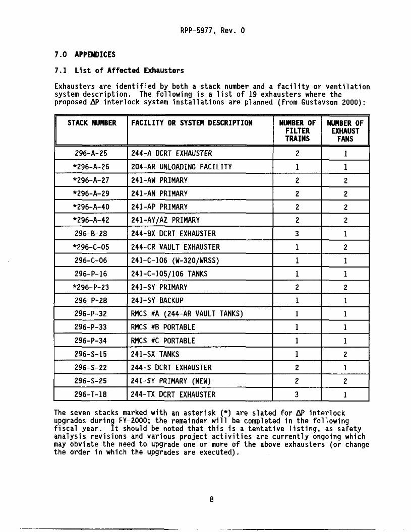
7 .1 L i s t o f Affected Exhausters
Exhausters are identified by both a stack number and a facility or ventilation system description. proposed AP interlock system installations are planned (from Gustavson 2000):
The following is a list of 19 exhausters where the
241-C-106 (W-320/WRSS) 1 1
241-C-105/106 TANKS 1 1
I I I
*296-A-26 I204-AR UNLOADING FACILITY I 1 1
*296-P-23
296-P-28
296-P-32
296-P-33
296-P-34
296-S-15
296-S-22
I *296-A-27 I241-AW PRIMARY
241-SY PRIMARY 2 2
241-SY BACKUP 1 1
RMCS #A (244-AR VAULT TANKS) 1 1
RMCS #B PORTABLE 1 1
RMCS #C PORTABLE 1 1
241-SX TANKS 1 2
244-S DCRT EXHAUSTER 2 1
1 2 I 7 I *296-A-29 I241-AN PRIMARY 1 2 I 7 I *296-A-40 I 2 4 1 - A P PRIMARY I 2 I 2 1
I *296-A-42 1241-AY/AZ PRIMARY I 2 I 2 I I 296-8-28 I244-BX DCRT EXHAUSTER I 3 I 1 I I *296-C-05 I244-CR VAULT EXHAUSTER I 1 I 2 I
~~
1 296-S-25 IZ41-SY PRIMARY [NEW)
I 296-T-18 I244-TX DCRT EXHAUSTER 1 3 I 1 I The seven stacks marked with an asterisk (*) are slated for AP interlock upgrades during FY-2000; the remainder will be completed in the following fiscal year. analysis revisions and various project activities are currently ongoing which may obviate the need to upgrade one or more o f the above exhausters (or change the order in which the upgrades are executed).
It should be noted that this is a tentative listing, as safety

RPP-5977, Rev. 0
7.2 Reference Drawings
The f o l l o w i n g i s a p a r t i a l l i s t i n g o f a f fec ted drawings, by system. A more complete l i s t i n g w i l l be developed i n t h e course o f d e f i n i t i v e design. Note, t h e s a l t w e l l po r tab le exhausters (296-P-43, 44, & 45) are not i n t h e scope o f t h e sub jec t upgrades. HEPA f i l t e r AP f an i n t e r l o c k c a p a b i l i t y , and were l i s t e d as reference drawings due t o t h e i r s i m i l a r i t y w i t h t h e proposed system.
However, these exhausters c u r r e n t l y f e a t u r e PLC-based
296-A-261204-AR Waste Unloadina Faci l i t v :
H-2-70695, E l e c t r i c a l Elementary Diagrams, W i r i n g Diagrams, Wi re Run L i s t and
H-2-70696, HVAC Schedules, Diagrams, and D e t a i l s .
H-2-70697, HVAC Plan, Sect ions, and D e t a i l s .
H-2-70701, Ins t rumenta t ion Plan, Sect ions, and D e t a i l s .
H-2-79852, E l e c t r i c a l Power Plan F i r s t F l o o r .
H-2-85195, E l e c t r i c a l One L ine Diagram.
H-2-92187, Air Mon i to r and Contro l I n s t a l l a t i o n and W i r i n g Diagrams.
Conduit Schedule.
296-A-271241-AW Primarv:
H-2-70324, Sheet 5, E l e c t r i c a l Plans and D e t a i l s .
H-2-70325, Sheets 2 & 4, E l e c t r i c Power and Contro l Elementary Diagram.
H-2-90909, HVAC - K1 System Equipment Schedules and Notes.
H-14-020102, V e n t i l a t i o n lank Primary System (VTP) O&M System P&ID.
H-14-030002, E l e c t r i c a l (EDS) One-Line Diagram.
296-A-291241-AN Primarv:
H-2-71925, E l e c t r i c a l Power and Contro l Plans and D e t a i l s .
H-2-71927, E l e c t r i c a l Power and Contro l Elementary Diagrams.
H-2-71959, Ins t rumenta t ion Annunciator Elementary Diagram.
H-2-71937, HVAC Equipment Schedules, D e t a i l s , and General Notes.
H-14-020101, V e n t i l a t i o n Tank Pr imary System ( V T P ) O&M System P&ID.

RPP-5977, Rev. 0
296-A-401241-AP Primarv:
H-2-90470, Electrical Power Distribution Plan, Sections, and Details.
H-2-90476, Electric Elementary Diagrams Centra7 Exhauster Station.
H-2-90477 (Sh. 10 & ll), Electrical Wire Run List, Central Exhaust Station.
H-2-90480, El ectrica 7 Relay Enclosures.
H-2-90516, HVAC Central Exhauster Station Primary System.
H-2-90522, HVAC Equipment Schedules and Notes.
H-2-90750, HVAC Details.
H-2-99085, Electrica 7 El emen tary Diagrams.
H-14-020103, Ventilation Tank Primary System (VTP) O&M System P&ID.
H-14-030003 (Sh. 3 ) , Electrical (EDS) One-Line Diagram.
H-14-030003 (Sh. 16) , Electrical (EDS) Panelboard Schedule.
296-A-421241-AYlAZ Primarv:
H-2-131266, HVAC Ventilation Facility Floor Plan.
H-2-131271, HVAC Equipment Schedules.
H-14-020107, Ventilation Tank Primary System (VTP) O&M System P&ID.
296-C-051244-CR Vault :
H-2-33279, Stack Gas Filter Arrangement.
H-2-41745, Heating and Ventilation Plan - Ductwork to Filter and Stack. H-2-41746, Heating and Ventilation Sections - Ductwork to Filter and Stack.
H-2-41781, Heating and ventilation Plan and Sections - Stack Exhaust Fans and
H-2-95308, Stack Gas Filter and DP Connector and Stand Assembly.
Platforms.
296-P-231241-SY Primarv:
H-2-37744, Ventilation Air Flow and Control Diagram.
H-2-37745, Ventilation Equipment Assembly.
H-2-37746, Ventilation Equipment Plan and Details.
10

RPP-5977, Rev. 0
H-2-37747, Ventilation Equipment Schedules.
H-14-020131, Ventilation Tank Primary System (VTP) O&M System P&ID.
H-14-030031, Sheet 2 , Electrical (EDS) One-Line Diagram.
296-S-15/241-SX Tanks:
H-2-35834, Vent Air Flow Diagram Tanks SX-105, 107, 108, 109, 110, 111, 112,
H-2-35835, Ventilation Plan and Details Tanks SX-105, 107, 108, 109, 110, 111,
H-14-020134, Ventilation Tank Primary System (VTP) O&M System P&ID.
and 114.
112, and 114.
296-S-221244-S DCRT:
H-2-71047, Ventilation Air Flow and Control Diagram and Schedule.
H-2-71048, Ventilation Plan and Details.
H-2-71085, Instrument at ion Engineering Flow Diagram.
H-2-71090, Electrical Plans and Details.
H-2-71092, Electrical Diagrams and Details.
H-14-030053, E lectrica 7 (EDS) One- L ine Diagram.
296-T-181244-TX DCRT:
H-2-73796, Engineering Flow Diagram System No. 1 .
H-2-73819, Electrical One-Line and Elementary Diagram System No. 2 .
11-2-73838, HVAC Airflow and Control Diagram and Schedule.
H-2-73839, HVAC Plans, Sections, and Details.
296-P-43&44&45/500-CFM Saltwell Portable Exhausters
H-2-829116, 500 CFM Portable Exhausters Piping and Instrument Diagram.
H-14-100868, Electrical Exhausters B, C, and D One-Line Diagram.
H-14-100869, Electrical Exhausters B, C, and D Parts List and Genera7 Notes.
H-14-100870, Electrical Exhausters B , C, and D Skid Details and Parts List.
11

I 1
To Distribution
DISTRIBUTION SHEET
Page 1 of 1 From
RPP-5977, HEPA Filter Differential Pressure Fan Interlock System Functional Requirements and Technical Design Criteria
EDTNo. 626597
ECN No. n/a
ID. G . Baide I 55-05 I X I I I I
Name Text Attach” EDTIECN M h All T e d Only Appendix Attach. Onlv Only
MSlN
I C . M. Lewis I R3-47 I X I I I I
K. E. Carpenter
R. D. Gustavson
T. D. Kaiser
R. E. Larson
t J. Lohrasbi I 55-05 I X I I I I
R3-47 X
R3-83 X T4-07 X
T4-07 X
C. C. Scaief I11
D. Scott Jr.
R. R. True
J. A. Tuck
W. E. Willinsham Jr.
I Jonathan Youna I K7-97 I X I I I I
R3-83 X 55-07 X
T4-07 X
R3-47 X
L6-37 X
A-BWO-I 35 (I omq