Embed Size (px)
Citation preview

3-GALLON OIL-FREE AIR COMPRESSOR
Operator's Manual Model:
TOLL FREE HELPLINE: 1-888-266-7096FOR SAFE OPERATION, READ AND UNDERSTANDALL CONTENTS OF THE INSTRUCTION MANUAL
Model 72704
1

SPECIFICATIONS.......................................................................................... SAFETY GUIDELINES ..................................................................................
GENERAL SAFETY RULES...........................................................................
GLOSSARY OF TERMS.................................................................................
ASSEMBLY.....................................................................................................
INSTALLATION...............................................................................................
OPERATION................................................................................................... MAINTENANCE ............................................................................................. TROUBLESHOOTING....................................................................................
EXPLODED VIEW/PARTS LIST.....................................................................
LIMITED WARRANTY ....................................................................................
Model No.: 72704
Motor.................................................................................120V 60Hz, 2.2-amp
Running Horsepower...............................................................................1/3 Hp
Tank Size...............................................................................................3-gallon
Pump Type..................................................Single Cylinder: Shaft direct drive
Air Hose Type.............................................................25’recoil, MAX. 100 PSI
Air Delivery...................................................................... 1.0 SCFM @ 40 PSI
0.6 SCFM @ 90 PSI
Cut-in Pressure........................................................................................85 PSI
Cut-out Pressure....................................................................................100 PSI
Max. Pressure........................................................................................100 PSI
Power Cord.....................................................................6ft, 3-prong, 18 AWG
Weight....................................................................................22.4 lb (10.2 kg)
2
23
IMPORTANT SAFETY INSTRUCTIONS ....................................................... 39
SPECIFIC SAFETY RULES............................................................................1112
ACCESSORIES INCLUDED.................................................................................1213
19
212627
29
32
TABLE OF CONTENTS
SPECIFICATIONS

SAFETY GUIDELINES - DEFINITIONS
Indicates animminently hazardous
situation which, if not avoided, willresult in death or serious injury.
Indicates apotentially
hazardous situation which, if notavoided, could result in death orserious injury.
Indicates apotentially hazardous
situation which, if not avoided, mayresult in minor or moderate injury.
Used without thesafety alert symbol
indicates a potentially hazardoussituation which, if not avoided, mayresult in property damage.
This manual contains information that is important for you to know andunderstand. This information relates to protecting YOUR SAFETY andPREVENTING EQUIPMENT PROBLEMS. To help you recognize thisinformation, we use the symbols below. Please read the manual and payattention to these symbols.
IMPORTANT SAFETY INSTRUCTIONSSome dust created by power sanding, sawing, grinding,drilling, and other construction activities contains chemicals
known (to the State of California) to cause cancer, birth defects or otherreproductive harm. Some example of these chemicals are:
lead from lead-based paintscrystalline silica from bricks and cement and other masonry productsarsenic and chromium from chemically-treated lumber
Your risk from these exposures varies, depending on how often you do thistype of work. To reduce your exposure to these chemicals: work in a wellventilated area, and work with approved safety equipment, always wearMSHA/NIOSH approved, properly fitting face mask or respirator when usingsuch tools.When using air tools, basic safety precautions should always be followed toreduce the risk of personal injury.
3

IMPORTANT SAFETY INSTRUCTIONS
Save these instructions
Improper operation or maintenance of this product could result in serious injury andproperty damage. Read and understand all warnings and operation instructions beforeusing this equipment.
HAZARD
WARNING: Risk of explosion or fire
How To Prevent ItWhat Could Happen
It is normal for electrical contacts withinthe motor and pressure switch to spark.
If electrical sparks from compressorcome into contact with flammablevapors, they may ignite, causing fire orexplosion.
Restricting any of the compressorventilation openings will cause seriousoverheating and could cause fire.
Unattended operation of this productcould result in personal injury orproperty damage. To reduce the risk offire, do not allow the compressor tooperate unattended.
Always operate the compressor in a wellventilated area free of combustiblematerials, gasoline, or solvent vapors.
If spraying flammable materials, locatecompressor at least 20 feet away fromspray area. An additional length of hosemay be required.Store flammable materials in a securelocation away from compressor.
Never place objects against or on topof compressor. Operate compressor inan open area at least 12 inches awayfrom any wall or obstruction that wouldrestrict the flow of fresh air to theventilation openings.Operate compressor in a clean, dry wellventilated area.
Always remain in attendance with theproduct when it is operating.Always disconnect electrical power bymoving pressure switch lever to the offposition and drain tank daily or aftereach use.
4

WARNING: Risk of Bursting
Air Tank: The following conditions could lead to a weakening of the tank, and resultin a violent tank explosion and could cause property damage or serious injury.
How To Prevent ItWhat Could Happen
WARNING: Risk from Flying Objects
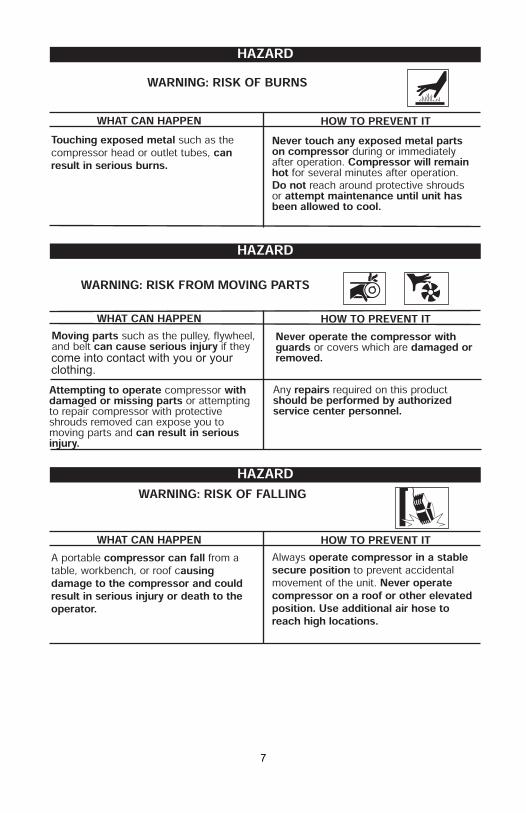
HOW TO PREVENT ITWHAT CAN HAPPEN
The compressed air stream can causesoft tissue damage to exposed skin andcan propel dirt, chips, loose particles,and small objects at high speed,resulting in property damage or personalinjury.
Always wear ANSI Z87.1 approvedsafety glasses with side shields whenusing the compressor.
Never point any nozzle or sprayertoward any part of the body or at otherpeople or animals.
Always turn the compressor off andbleed pressure from the air hose andtank before attempting maintenance,attaching tools or accessories.
HAZARD
HAZARD
Drain tank daily or after each use. Iftank develops a leak, replace itimmediately with a new tank or replacethe entire compressor.
1. Failure to properly draincondensed water from tank,causing rust and thinning of thesteel tank.
2. Modifications or attempted repairsto the tank.
3. Unauthorized modifications to theunloader valve, safety valve, or anyother components which controltank pressure.
Never drill into, weld, or make anymodifications to the tank or itsattachments.
4. Excessive vibration can weakenthe air tank and cause rupture orexplosion
The tank is designed to withstand specificoperating pressures. Never makeadjustments or parts substitutions toalter the factory set operatingpressures.
For essential control of air pressure, youmust install a pressure regulator andpressure gauge to the air outlet (if notequipped) of your compressor. Follow theequipment manufacturersrecommendation and never exceed themaximum allowable pressure rating ofattachments. Never use compressor toinflate small low pressure objects suchas children’s toys, footballs,basketballs, etc.
ATTACHMENTS & ACCESSORIES:Exceeding the pressure rating of airtools, spray guns, air operatedaccessories, tires, and other inflatablescan cause them to explode or fly apart,and could result in serious injury.
5

HOW TO PREVENT ITWHAT CAN HAPPEN
WARNING: Risk to Breathing
WARNING: Risk of Electric Shock
HOW TO PREVENT ITWHAT CAN HAPPEN
HAZARD
HAZARD
Your air compressor is powered byelectricity. Like any other electricallypowered device, If it is not used properlyit may cause electric shock.
Repairs attempted by unqualifiedpersonnel can result in serious injury ordeath by electrocution.
Electrical Grounding: Failure to provideadequate grounding to this productcould result in serious injury or deathfrom electrocution. See grounding instructions.
Never operate the compressor outdoorswhen it is raining or in wet conditions.Never operate compressor withprotective covers removed or damaged.
Any electrical wiring or repairs requiredon this product should be performed byauthorized service center personnel inaccordance with national and localelectrical codes.
Make certain that the electrical circuitto which the compressor is connectedprovides proper electrical grounding,correct voltage and adequate fuseprotection.
The compressed air directly from yourcompressor is not safe for breathing.The air stream may contain carbonmonoxide, toxic vapors, or solidparticles from the tank. Breathing thesecontaminants can cause serious injuryor death.
Sprayed materials such as paint, paintsolvents, paint remover, insecticides,weed killers, may contain harmful vaporsand poisons.
Air obtained directly from the compressorshould never be used to supply air forhuman consumption. In order to use airproduced by this compressor forbreathing, suitable filters and in-linesafety equipment must be properlyinstalled. In-line filters and safetyequipment used in conjunction with thecompressor must be capable of treatingair to all applicable local and federalcodes prior to human consumption.
Work in an area with good crossventilation. Read and follow the safetyinstructions provided on the label orsafety data sheets for the materials youare spraying. Use a NIOSH/ MSHAapproved respirator designed for usewith your specific application.
6
7
come into contact with you or yourclothing.

Review and understand all instructionsand warnings in this manual.Become familiar with the operation andcontrols of the air compressor.Keep operating area clear of all persons,pets, and obstacles.Keep children away from the aircompressor at all times.Do not operate the product whenfatigued or under the influence ofalcohol or drugs. Stay alert at all times.Never defeat the safety features of thisproduct.Equip area of operation with a fireextinguisher.Do not operate machine with missing,broken, or unauthorized parts.
HOW TO PREVENT ITWHAT CAN HAPPEN
WARNING: RISK OF UNSAFE OPERATION
Unsafe operation of your air compressorcould lead to serious injury or death toyou or others.
HAZARD
HOW TO PREVENT ITWHAT CAN HAPPEN
WARNING: RISK OF SERIOUS INJURY OR PROPERTYDAMAGE WHEN TRANSPORTING COMPRESSOR
Oil can leak or spill and could result infire or breathing hazard; serious injury ordeath can result. oil leaks will damagecarpet, paint or other surfaces in vehiclesor trailers.
Always place COMPRESSOR on aprotective mat when transporting toprotect against damage to vehicle fromleaks. Remove COMPRESSOR fromvehicle immediately upon arrival at yourdestination.
(Fire, Inhalation, Damage to Vehicle Surfaces)
HAZARD
8

GENERAL SAFETY RULES
9
WORK AREAKeep your work area clean and well lit. Cluttered benches and dark areas invite accidents.Do not operate power tools in explosive atmospheres, such as in the presence of flammable liquids, gases, or dust. Power tools create sparks which may ignite the dust or fumes.Keep bystanders, children, and visitors away while operating a power tool. Distractions can cause you to lose control. Protect others in the work area from debris such as chips and sparks. Provide barriers or shields as needed.
ELECTRICAL SAFETYGrounded tools must be plugged into an outlet properly installed and grounded in accordance with all codes and ordinances. Never remove the grounding prong or modify the plug in any way. do not use any adapter plugs. Check with a qualified electrician if you are in doubt as to whether the outlet is properly grounded. If the tools should electrically malfunction or break down, grounding provides a low resistance path to carry electricity away from the user.Double insulated tools are equipped with a polarized plug (one blade is wider than the other). This plug will fit in a polarized outlet only one way. If the plug does not fit fully in the outlet, reverse the plug. If it still does not fit, contact a qualified electrician to install a polarized outlet. do not change the plug in any way. Double insulation eliminates the need for the three wire grounded power cord and grounded power supply system.Avoid body contact with grounded surfaces such as pipes, radiators, ranges, and refrigerators. There is an increased risk of electric shock if your body is grounded.Do not expose power tools to rain or wet conditions. Water entering a power tool will increase the risk of electric shock.Do not abuse the Power Cord. Never use the Power Cord to carry the tools or pull the Plug from an outlet. keep the Power Cord away from heat, oil, sharp edges, or moving parts. Replace damaged Power Cords immediately. Damaged Power Cords increase the risk of electric shock.When operating a power tool outside, use an outdoor extension cord marked “W-A” or “W”. These extension cords are rated for outdoor use, and reduce the risk of electric shock.
PERSONAL SAFETYStay alert. watch what you are doing, and use common sense when operating a power tool. do not use a power tool while tired or under the influence of drugs, alcohol, or medication. A moment of inattention while operating power tools may result in serious personal injury.Dress properly. do not wear loose clothing or jewelry. Contain long hair. Keep your hair, clothing, and gloves away from moving parts. Loose clothes, jewelry, or long hair can be caught in moving parts.

GENERAL SAFETY RULES
10
Avoid accidental starting. be sure the Power Switch is off before plugging in. Carrying power tools with your finger on the Power Switch, or plugging in power tools with the Power Switch on, invites accidents.Remove adjusting keys or wrenches before turning the power tool on. A wrench or a key that is left attached to a rotating part of the power tool may result in personal injury. Do not overreach. keep proper footing and balance at all times. Proper footing and balance enables better control of the power tool in unexpected situations. Use safety equipment. Always wear eye protection. Dust mask, nonskid safety shoes, hard hat, or hearing protection must be used for appropriate conditions. Always wear ANSI-approved safety goggles and a dust mask/respirator when using or performing maintenance on this tool.
TOOL USE AND CAREUse clamps (not included) or other practical ways to secure and support the work piece to a stable platform. Holding the work by hand or against your body is unstable and may lead to loss of control.Do not force the tool. use the correct tool for your application. The correct tool will do the job better and safer at the rate for which it is designed. Do not force the tool and do not use the tool for a purpose for which it is not intended.Do not use the power tool if the Power Switch does not turn it on or off. Any tool that cannot be controlled with the Power Switch is dangerous and must be replaced.Disconnect the Power Cord Plug from the power source before making any adjustments, changing accessories, or storing the tool. Such preventive safety measures reduce the risk of starting the tool accidentally. Store idle tools out of reach of children and other untrained persons. Tools are dangerous in the hands of untrained users. Keep children away from.Maintain tools with care. Properly maintained tools are less likely to bind and are easier to control. Do not use a damaged tool. Tag damaged tools “Do not use” until repaired.Check for misalignment or binding of moving parts, breakage of parts, and any other condition that may affect the tool’s operation. If damaged, have the tool serviced before using. Many accidents are caused by poorly maintained tools.Use only accessories that are recommended by the manufacturer for your model. Accessories that may be suitable for one tool may become hazardous when used on another tool.
SERVICETool service must be performed only by qualified repair personnel. Service or maintenance performed by unqualified personnel could result in a risk of injury.

SPECIFIC SAFETY RULES
11
Maintain labels and nameplates on the Air Compressor. These carry important information. If unreadable or missing, contact toll free helpline: 1-888-266-7096 for a replacement.Always wear ANSI-approved safety impact eye goggles and heavy work gloves when using the Air Compressor. Using personal safety devices reduce the risk for injury. Safety impact eye goggles and heavy work gloves are available from SEARS CANADA.Maintain a safe working environment. Keep the work area well lit. Make sure there is adequate surrounding workspace. Always keep the work area free of obstructions, grease, oil, trash, and other debris. Do not use a power tool in areas near flammable chemicals, dusts, and vapors. Do not use this product in a damp or wet location.Avoid unintentional starting. Make sure you are prepared to begin work before turning on the Air Compressor.Do not force the Air Compressor. This tool will do the work better and safer at he pressure and capacity for which it was designed.Always unplug the Air Compressor from its electrical outlet before performing any inspection, maintenance, or cleaning procedures. Before each use, check all nuts, bolts, and screws for tightness. Vibra-tion may cause these to loosen.Drain compressor every day. Do not allow moisture to build up inside the compressor.Make sure all equipment is rated to the appropriate capacity. Adjust the output air pressure to the tool’s operating capacity.Avoid explosions and fire. Never place flammable objects near the compres-sor. Never spray water or any flammable liquids towards the compressor.Avoid bodily injury. Never direct the air outlet at persons or animals.Never leave the air tool unattended when it is plugged into the air compressor. Turn off the tool, and unplug it from air compressor outlet before leaving. WARNING! People with pacemakers should consult their physician(s) before using this product. Electromagnetic fields in close proximity to a heart pacemaker could cause interference to or failure of the pacemaker.
Become familiar with these terms before operating the unit.CFM: Cubic feet per minute.SCFM: Standard cubic feet per minute; a unit of measure of air delivery.PSI: Pounds per square inch ; a unit of measure of pressure.Code Certification: Products that bear one or more of the following marks:UL, CUL, ETL, CETL, have been evaluated by OSHA certified independentsafety laboratories and meet the applicable Underwriters LaboratoriesStandards for Safety.Cut-In Pressure: While the motor is off, air tank pressure drops as youcontinue to use your accessory. When the tank pressure drops to a certain lowlevel the motor will restart automatically. The low pressure at which the motorautomatically restarts is called "cut-in" pressure.Cut-Out Pressure: When an air compressor is turned on and begins to run,air pressure in the air tank begins to build. It builds to a certain high pressurebefore the motor automatically shuts off - protecting your air tank frompressure higher than its capacity. The high pressure at which the motor shutsoff is called "cut-out" pressure.Branch Circuit: Circuit carrying electricity from electrical panel to outlet.
DUTY CYCLEAir compressors should be operated on not more than a 50% duty cycle. This means an air compressor that pumps air more than 50% of one hour is considered misuse, because the air compressor is undersized for the required air demand. Maximum compressor pumping time per hour is 30 minutes.
12
GLOSSARY OF TERMS
ACCESSORIES INCLUDED
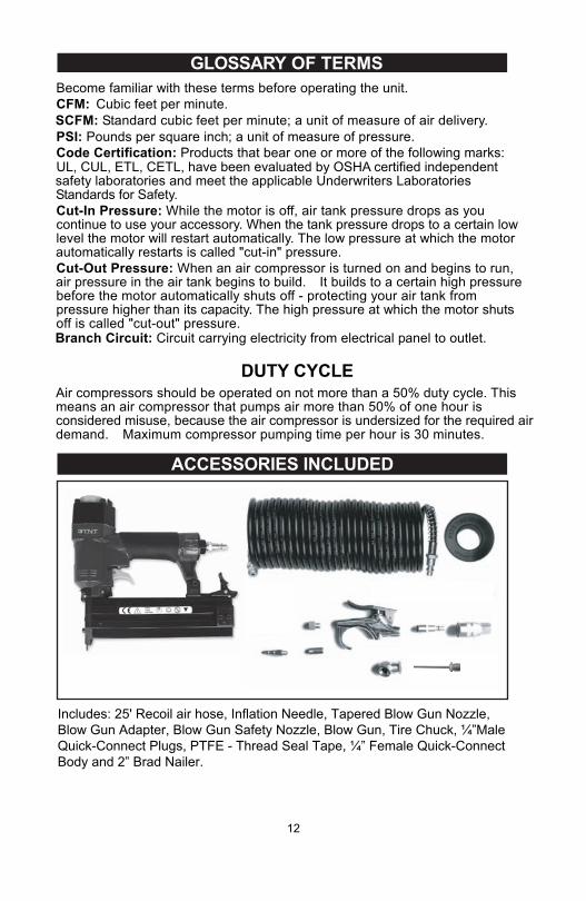
Includes: 25' Recoil air hose, Inflation Needle, Tapered Blow Gun Nozzle, Blow Gun Adapter, Blow Gun Safety Nozzle, Blow Gun, Tire Chuck, ¼”Male Quick-Connect Plugs, PTFE - Thread Seal Tape, ¼” Female Quick-Connect Body and 2” Brad Nailer.

ASSEMBLYUNPACKINGThis product has been shipped completely assembled. Carefully remove the tool and any accessories from the box. Mark sure that all items listed in the packing list are included. Inspect the tool carefully to make sure no breakage or damage occurred during shipping. Do not discard the packing material until you have carefully inspected and satisfactorily operated the tool. If any parts are damaged or missing, please call 1-888-266-7096 for assistance.
PACKING LISTAir CompressorAccessories (11)Operator’s Manual (not shown)
13
1
2
3
4
6
9
11
12
10
8
75
1 air compressor2 2” Brad Nailer3 25' Recoil air hose4 Inflation Needle5 Tapered Blow Gun Nozzle6 Blow Gun Adapter7 Blow Gun Safety Nozzle8 Blow Gun9 Tire Chuck10 ¼”Male Quick-Connect Plugs11 PTFE - Thread Seal Tape12 ¼” Female Quick-Connect Body13 Operator’s Manual (not shown)
Includs:
14
ASSEMBLY
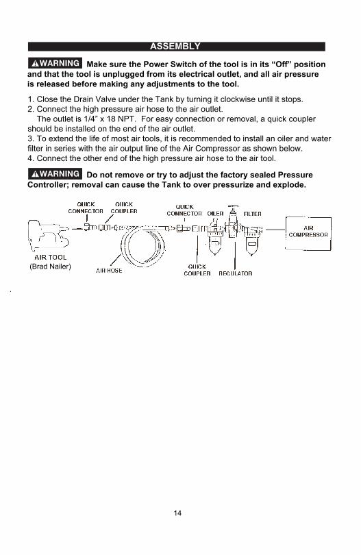
Make sure the Power Switch of the tool is in its “Off” position and that the tool is unplugged from its electrical outlet, and all air pressure is released before making any adjustments to the tool.
Do not remove or try to adjust the factory sealed Pressure Controller; removal can cause the Tank to over pressurize and explode.
1. Close the Drain Valve under the Tank by turning it clockwise until it stops.2. Connect the high pressure air hose to the air outlet. The outlet is 1/4” x 18 NPT. For easy connection or removal, a quick coupler should be installed on the end of the air outlet.3. To extend the life of most air tools, it is recommended to install an oiler and water filter in series with the air output line of the Air Compressor as shown below.4. Connect the other end of the high pressure air hose to the air tool.
(Brad Nailer)

Attaching Air Hose To Compressor1. 2.
NOTE: When connecting or disconnecting air hose remove air from tank.
15
ASSEMBLY
Using your left hand push quick connect towards the body of the compressor.Firmly press fit the male quick connect portion on the air hose into the female quick connect and release female quick connect locking hose in place.
Fig. A

Assemble AccessoriesThe unit is supplied with an accessory kit and inflator/deflator kit, choose the accessory needed.
Assemble Accessory Kit (See Fig. B)To Assemble Female Tire Chuck1. Assemble female tire chuck (a) to hose (b) and tighten securely with wrenches.To Assemble Accessories 1. Attach the blow gun (c) to hose (b).
2. Assemble the safety nozzle (d) or blow gunadapter (e) to blow gun. NOTE :To use the inflating needle (f) or the tapered inflator (g), need to use the blow
gun adapter (e) to assembled to the blow gun 3. Attach the inflation needle(f) to the blow gun adapter on the blower gun.
16
ASSEMBLY
Fig. B
Risk of unsafe operation. If an accessory is not being used with the blow gun, the safety nozzle MUST be assembled.
g
f
e
a
c
b
d

17
ASSEMBLY
Assembling Inflation Needle Or Tapered NozzleThe blow gun (c) and blow gun adapter (e) from the accessory kit is needed to usethe inflator/deflator kit. (See Fig. C/Fig. D) 1. Attach the blow gun to hose. 2. Attach blow gun adapter to blow gun. 3. Attach the inflation needle (f), tapered nozzle (g).
Safety Nozzle
Fig. C
Fig. D
g
f
ec
18
ASSEMBLY
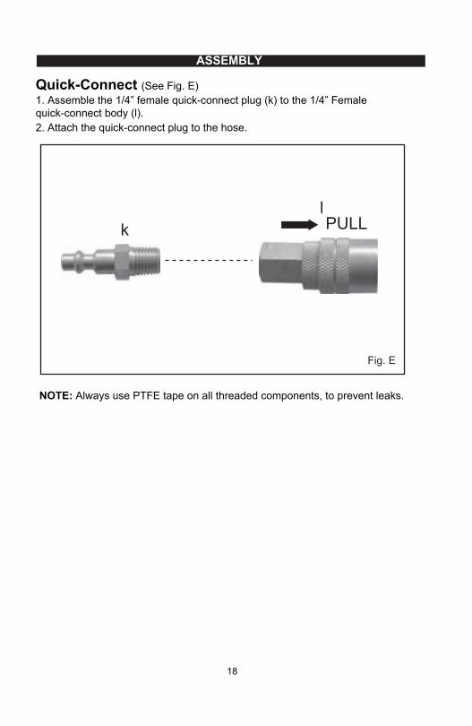
Quick-Connect (See Fig. E)1. Assemble the 1/4” female quick-connect plug (k) to the 1/4” Femalequick-connect body (l). 2. Attach the quick-connect plug to the hose.
lk
Fig. E
NOTE: Always use PTFE tape on all threaded components, to prevent leaks.
PULL

19
INSTALLATION
GROUNDING INSTRUCTIONSDANGER! Risk of Electric Shock. In the event of a short circuit, grounding reduces the risk of shock by providing an escape wire for the electric current. This air compressor must be properly grounded.The portable air compressor is equipped with a cord having a grounding wire with an appropriate grounding plug (see following illustrations). The plug must be used with an outlet that has been installed and grounded in accordance with all local codes and ordinances. 1. The cord set and plug with this unit contains a grounding pin. This plug MUST be used with a grounded outlet.IMPORTANT: The outlet being used must be installed and grounded in accordance with all local codes and ordinances. 2. Make sure the outlet being used has the same configuration as the grounded plug. DO NOT USE AN ADAPTER. (See illustration)3. If these grounding instructions are not completely understood, or if in doubt as to whether the compressor is properly grounded, have the installation checked by a qualified electrician. Risk of Electric Shock. IMPROPER GROUNDING CAN RESULT IN ELECTRICAL SHOCK. Do not modify the plug provided. If it does not fit the available outlet, a correct outlet should be installed by a qualified electrician. Repairs to the cord set or plug MUST be made by a qualified electrician.
3-Prong Plug and Outlet
Grounding pin
GroundedOutlets
Plug
20
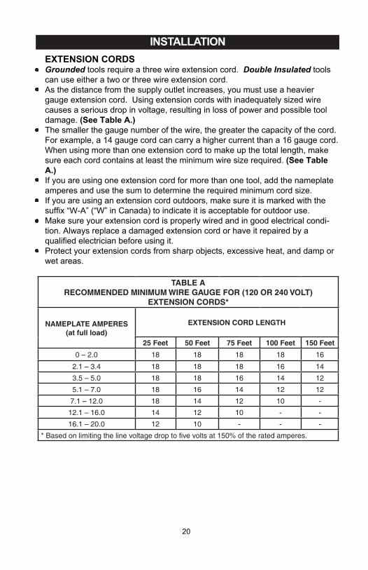
INSTALLATION EXTENSION CORDSGrounded tools require a three wire extension cord. Double Insulated tools can use either a two or three wire extension cord.As the distance from the supply outlet increases, you must use a heavier gauge extension cord. Using extension cords with inadequately sized wire causes a serious drop in voltage, resulting in loss of power and possible tool damage. (See Table A.)The smaller the gauge number of the wire, the greater the capacity of the cord. For example, a 14 gauge cord can carry a higher current than a 16 gauge cord.When using more than one extension cord to make up the total length, make sure each cord contains at least the minimum wire size required. (See Table A.)If you are using one extension cord for more than one tool, add the nameplate amperes and use the sum to determine the required minimum cord size.If you are using an extension cord outdoors, make sure it is marked with the suffix “W-A” (“W” in Canada) to indicate it is acceptable for outdoor use.Make sure your extension cord is properly wired and in good electrical condi-tion. Always replace a damaged extension cord or have it repaired by a qualified electrician before using it.Protect your extension cords from sharp objects, excessive heat, and damp or wet areas.
TABLE ARECOMMENDED MINIMUM WIRE GAUGE FOR (120 OR 240 VOLT)
EXTENSION CORDS*
NAMEPLATE AMPERES(at full load)
EXTENSION CORD LENGTH
25 Feet 50 Feet 75 Feet 100 Feet 150 Feet0 – 2.0 18 18 18 18 16
2.1 – 3.4 18 18 18 16 14
3.5 – 5.0 18 18 16 14 12
5.1 – 7.0 18 16 14 12 12
7.1 – 12.0 18 14 12 10 -
12.1 – 16.0 14 12 10 - -
16.1 – 20.0 12 10 - - -
* Based on limiting the line voltage drop to five volts at 150% of the rated amperes.

21
OPERATION KNOW YOUR AIR COMPRESSORREAD THIS OWNER'S MANUAL AND SAFETY RULES BEFORE OPERATING YOUR UNIT. Compare the illustrations with your unit to familiarize yourself with the location of various controls and adjustments. Save this manual for future reference.
Overload Protector
Output Air Pressure
Power Switch
Tank AirPressure Gauge
Air Release Safety Valve
PressureAdjustment
Air Outlet
Quick-connectCoupler
Gauge

22
OPERATION
TURNING COMPRESSOR ON1. Pull and release the Air Release Safety Valve to verify it does not stick.2. Plug the power cord into a grounded electrical outlet.3. Press the Power Switch to the On position.4. Allow the Tank to fill to 85 PSI before using.With the Air Compressor turned on, operation is automatic and under the control of the internal Pressure Controller.
PRESSURE ADJUSTMENTSet the appropriate air pressure output for the air tool being used.1. Turn the Pressure Adjustment knob to the left to decrease output air pressure, or to the right to incease the output air pressure.2. Read the air output pressure on the Output Air Pressure Gauge.
USING THE AIR RELEASE SAFETY VALVEThe Air Release Safety Valve is used when tank decompression is needed quickly and efficiently. 1. Press the Power Switch to the Off position.2. Pull on the Air Release Safety Valve ring to release pressure from the Tank. 3. When all pressure is released, let go of the ring on the Air Release Safety Valve.
EMPTY AIR AND CONDENSATIONThe water Drain Valve is located underneath the Air Tank. It must be used daily to release all trapped moisture through this valve. It will also get rid of any condensa-tion that may cause tank corrosion.
1. Press the Power Switch to the Off position.2. Unscrew the water Drain Valve two to three turns counterclockwise.3. When all the moisture is released, turn the Drain Valve clockwise until it is tight.
Slightly open the water Drain Valve to blow air and moisture out of the Tank. Opening it all the way may cause it to be blown off.
OPERATING COMPRESSOR

23
OPERATION
1. Press the magazine release button to open the magazine.(See Fig. F) 2. Slide the magazine open and insert a strip of fasteners.(See Fig. G) 3. Push the magazine closed from the bottom. Make sure the nails slide freely in the magazine. (See Fig. H) 4. The magazine should lock closed. If it does not, open and make sure the nails are flat against the tray of the magazine. 5. Connect the tool to the air supply. Make sure the air supply is in the correct PSI range (see Operating Instructions). 6. Never operate the tool unless the tip of the nailer is in contact with the workpiece. Do not operate the tool without fasteners loaded or damage to the tool may result.
Always disconnect the tool from the air supply before loading. When loading the tool always aim the tool away from yourself and others. Make sure that the trigger is not pressed while the tool is being loaded.
OPERATING BRAD NAILER
Release Button
Fig. F Fig. G
Fig. H

24
OPERATION
IMPORTANT:Never exceed the maximum or minimum pressure. Pressure that is too low or too high may cause excess noise, wear, and/or misfiring. When connecting the air supply, keep hands and body away from the discharge area of the nailer. A filter regulator/oiler is required and should be located on the air line as close to the tool as possible. Keep the air filter clean. A dirty filter will reduce the air pressure supplied to the tool causing a reduction in power and efficiency. For better performance, install quick-connectors on your tool and a quick coupler on the air hose. For the best performance, make sure all connections in the air supply are tightly sealed to prevent air loss.

25
OPERATION
Place the tire gauge opening on the valve stem of the tire and firmly hold in place for at least 2 seconds. If required check twice for accuracy.The side wall of your tire will specify the maximum PSI or KPA rating however the pressure level for everyday driving will be specified in your vehicles manual and should be followed. It is suggested to review your vehicles owners manual for optimum tire pressure by season or contact your tire manufacturer for more details. NOTE: Check tire condition and pressure at least once a month and before any long trip. Never exceed the maximum cold tire inflation pressure shown on the tire side wall. The tire pressures should be checked when the tires are cold. On hot days the pressures will be 4 to 8 psi (28 - 50 KPA) higher after high speed driving.NOTE: The Tire Gauge is NOT INCLUDED in the accessories.
USING THE TIRE CHUCK1. Connect tire chuck to hose using PTFE tape on threads. You may also attach the tire chuck to a male quick connect for quick and easy removal in the future.2. Connect hose to compressor and turn switch to ON position. Allow pressure to build up to maximum pressure level in tank.3. Adjust regulator pressure to MAXIMUM position. In maximum output pressure position 135psi the tire will fill up quicker and accurately however it is extremely important to monitor the air flow using the tire gauge as it is in process of being filled to ensure of not overfilling tire. NOTE: If maximum pressure is not used for output of the compressor to tire than the tire may not fill as there may be a pressure lock between the tire and the hose which is normal. Due to this always use maximum pressure from compressor and continue to monitor pressure with gauge.4. Place tire chuck on tire valve stem and press firmly into place to prevent air from leaking out of tire. 5. Remove tire chuck from valve stem and check pressure using a tire gauge. This process needs to be followed throughout the process of filling each tire to ensure of accuracy and to prevent overfilling..
USING THE TIRE PRESSURE GAUGE

26
MAINTENANCE MAINTENANCE OF COMPRESSOR
MAINTENANCE OF BRAD NAILER
Make sure the Power Switch of the tool is in its “OFF” position and that the tool is unplugged from its electrical outlet before performing any inspection, maintenance, or cleaning procedures.
Disconnect the tool from the air supply before performing any adjustments, cleaning, maintenance, or repair.
1. BEFORE EACH USE, inspect the general condition of the tool. Check for loose screws, misalignment or binding of moving parts, cracked or broken parts, damaged electrical wiring, and any other condition that may affect its safe opera-tion. If abnormal noise or vibration occurs, have the problem corrected before further use. Do not use damaged equipment.2. Purge the Air Tank daily of all air and condensation to prevent corrosion.3. Store the Air Compressor in a clean and dry location.4. Check all air fittings for leaks before using.
• Regular lubrication should be performed if your tool is used without an in-line automatic oiler. Place 2–6 drops of air tool oil into the air inlet before each workday and after every 2 hours of continuous use. • Check all connections and o-rings. Change all worn or damaged o-rings, seals, etc. Tighten all the screws and caps to prevent potential damage or injury.• Inspect the trigger and safety mechanisms to ensure they are working properly. Check for loose or missing parts, binding, and/or sticking parts and adjust or replace accordingly.• Keep the nail magazine and the firing tip of the tool clean and free of any foreign particles or objects.

TROUBLESHOOTING TROUBLESHOOTING OF COMPRESSOR
Problem Possible Causes Probable SolutionsAir Compressor will not start
Power Switch in Off position.No power at outlet.Line cord not plugged in.
Push Power Switch to On position.Check power at outlet.Plug line cord into electrical outlet.
Tank air pressure does not reach 90 PSI and Air Compressorruns continuously.
Air Leaking at Drain Valve.Air hose has leak.
Tighten Drain Valve.Tighten or repair air hose.
Air tool not operating at proper speed.
Air output pressure low.
Air hose has leak.
Adjust Pressure Adjustment knob so Air Output Pressure Gauge reads air tool’s proper operating pressure.Tighten or repair air hose.
27

TROUBLESHOOTING TROUBLESHOOTING OF BRAD NAILER
Tool jams
28
1. Incorrect or damaged fasteners.2. Damaged or worn driver guide. 3. Magazine or nose screw loose. 4. Magazine is dirty.
1. Change and use correct fasteners. 2. Check and replace the driver guide. 3. Tighten the magazine. 4. Clean the magazine.
Problem Possible Causes Probable SolutionsAir leak near the topof the tool or in thetrigger area
1. O-ring in trigger valve damaged. 2. Trigger valve head damaged. 3. Trigger valve stem, seal, or O-ringdamaged.
3. Worn or damaged O-rings or seals.4. Exhaust port in cylinder head isblocked.
1. Push Power Switch to On position.2. Check power at outlet.3. Plug line cord into electrical outlet.
Air leak near bottomof tool.
1. Loose screws2. Worn or damaged O-rings or bumper.
1.Tighten screws.2. Check and replace O-rings and/orbumper.
Air leak between bodyand cylinder cap.
Fasteners being driventoo deep.
1. Loose screws.2. Worn or damaged O-rings or seals.
1. Worn bumper.2. Air pressure is too high.
1. Replace bumper.2. Adjust air pressure.
Too does not functionwell, does not drivefasteners, operatessluggishly.
Tool skips fasteners
1. Inadequate air supply.2. Inadequate lubrication.
1. Verify adequate air supply.2. Place 2–6 drops of oil into air inletto lubricate.
1. Tighten screws.2. Check and replace O-rings or seals.
If any of the following problems arise during operation, stop using the tool immediately. Only a qualified technician or authorized service centre can perform repairs on this tool. Disconnect the tool from the air supply before any repair or adjustment. When replacing O-rings or cylinders, lubricate with air tool oil before reassembly.
3. Check and replace O-rings or seals.4. Consult Authorized servicetechnician to replace internal parts.
1. Worn bumper or damaged loading spring. 2. Dirt in front plate. 3. Dirt or damage is preventing fasteners from moving freely in the magazine. 4. Worn or dried-out O-ring on piston, or lack of lubrication. 5. Cylinder cover seal leaking.
1. Replace bumper or loading spring.
2. Clean drive channel on front plate. 3. Clean magazine.
4. O-ring needs to be replaced or lubricated.5. Replace sealing washer.

EXPLODED VIEW/PARTS LIST
29
Fig.1

EXPLODED VIEW/PARTS LIST
30
Fig. 2
Fig. 3

31
No Model Num. Description Qty1 2 3 4 5 6 7 8 9 10 11 12 13 14 15 16 17
181920212223
24
25
26
2728293031323334
31102523110752-13020252302015232202503420350364015234105523110152-1322084032906513410302-1322047534103523630252-23630150-23410452
11224411121111111
Motor Assy.Pressure regulator Assy.Copper connector knob
Power cordCover, bottomCircuit board
ScrewCover, upper
Wire clip
Overload protector
ScrewWasher
Power switchTooling cover
ScrewDamping pad
Copper hoop
No Model Num. Description Qty
32204043410652-1322055232904083290250341032932205753330152-5329027534201503630152-134101523290252322015032907503390250-13111352
41222111131116611
ScrewHandleScrewFlat washer
Zip tieScrewAir tankDrain valveRubber footPressure controllerBallSpringScrewFlat washerCopper tubeElectric wire Assy.
Spring washer
EXPLODED VIEW/PARTS LISTCOMPRESSOR (Fig. 1)
No Model Num. Description Qty1 2 3 4 5 6 7 8 9 10 11 12 13
141516171819
20
21
22232425
361015233203503220152321020833101523420352349015034906503290650331055033102523490350-13310250
1111111111111
MotorCrankHex head screw
Piston ringPaper padHoop
Cylinder headSilica gel ring
CylinderCylinder washer
Connecting rodSilica gel ring
Bearing
No Model Num. Description Qty
375015034903503220610329030532907063410350-13220205365010134905523410150-130301503220650
214551122116cm3
Copper connectorSilica gel ringScrewFlat washer
FanScrewFlag terminalFlag terminal bushingMuffler boardTubeScrew
Spring washer
MOTOR (Fig. 2)
No Model Num. Description Qty1 2 3 4 5 6 7 8 9 10
11121314151617181920
331035234205523340152-13420452342085237502523420352-1342025233402523330252
1111111111
Pressure regulatorSeal ringSpring
Seal ringPistonSpringSpring board
Rubber washerHex cap
Seal ring
No Model Num. Description Qty
332025233104523110852-13190350319035231902523420652332045233203523321175
1111111111
Hex spring capPressure regulator coverPressure regulator knobSafety valve
Pressure gaugeSeal ringNutConnectorMale quick connect coupler
Pressure gauge
PRESSURE REGULATOR (Fig. 3)
WARRANTY
32
For TWO YEARS from the date of purchase within Canada, SEARS CANADA will, at its option, repair or replace for the original purchaser, free or charge, any part or parts found to be defective in material or workmanship.
This warranty does not cover: 1. Any part that has become inoperative due to misuse, commercial use, abuse, neglect, accident, improper maintenance, or alteration; or 2. The unit, if it has not been operated and/or maintained in accordance with the owner's manual; or 3. Normal wear, except as noted below; 4. Routine maintenance items such as lubricants, blade sharpening; 5. Normal deterioration of the exterior finish due to use or exposure.
Full One Hundred Twenty Days Warranty on Normal Wear Parts: Normal wear parts are defined as blade adaptors, blades, grass bags and tires. These parts are warranted to the original purchaser to be free from defects in material and workmanship for a period of one hundred twenty (120) days from the date of retail purchase.
How to Obtain Service: Warranty service is available by calling the toll-free helpline, at 1-888-266-7096.The factory will not accept the return of a complete unit unless prior written permission has been extended by SEARS CANADA.
Transportation Charges: Transportation charges for the movement of any power equipment unit or attachment are the responsibility of the purchaser. The purchaser must pay transportation charges for any part submitted for replace-ment under this warranty unless such return is requested in writing by SEARS CANADA.
Other Warranties: All other warranties, express or implied, including any implied warranty of merchantability is limited in its duration to that set forth in this express limited warranty. The provisions as set forth in this warranty provide the sole and exclusive remedy of obligations arising from the sale of its products.
SEARS CANADA will not be liable for incidental or consequential loss or damage.