Embed Size (px)
Citation preview

Doc. No. 2716DIGRevision A, October 2001
2716D DeviceNet ModuleInstallation Guide
Copyright © 2001 Control Technology CorporationAll Rights Reserved.
Printed in USA
Control Technology Corporation proprietary. Reproduction or distribution forbidden.
The information in this document is subject to change without notice. The software described inthis document is provided under license agreement and may be used or copied only inaccordance with the terms of the license agreement.The information, drawings, and illustrations contained herein are the property of ControlTechnology Corporation. No part of this manual may be reproduced or distributed by anymeans, electronic or mechanical, for any purpose other than the purchaser’s personal use,without the express written consent of Control Technology Corporation.The following are trademarks of Control Technology Corporation:
• Quickstep• CTC Monitor• CTC Utilities
The American Advantage is a registered trademark of Control Technology Corporation.MS-DOS and Windows are trademarks of Microsoft Corporation.DeviceNet is a trademark of Allen-Bradley Company.
This manual is printed on recycled paper.

Contents iii
Control Technology Corporation proprietary. Reproduction or distribution forbidden.
Contents
Notes to Readers .........................................................................vii
1 Getting Started ........................................................................... 1-1System Description .................................................................................1-2LEDs and Communications Terminals....................................................1-4Specifications 1-5Hardware/Firmware Revision Levels ......................................................1-6Board Handling Precautions ...................................................................1-7DeviceNet Hardware Configuration ........................................................1-8
Setting the Baud Rate ......................................................................1-8Setting the MACID ............................................................................1-9
Installing the 2716D Module .................................................................1-10Connecting the 2716D to a Network ....................................................1-12
General Setup Information .............................................................1-13Configuring Master Devices ...........................................................1-14
Disabling Master Mode .......................................................1-18Configuring Slave Devices .............................................................1-19
I/O Caveats 1-22Port Addressing ....................................................................................1-24Computer Based Programming and Communications .........................1-25
2 DeviceNet Technical Overview ................................................. 2-1DeviceNet Concepts ...............................................................................2-2
Theory of Operation..........................................................................2-3Scanning Characteristics ......................................................2-3Data Mapping ........................................................................2-4
iv 2716D DeviceNet Module Installation Guide
Control Technology Corporation proprietary. Reproduction or distribution forbidden.
Contents
DeviceNet Objects ............................................................................2-5Messages .........................................................................................2-5Master Device Types ........................................................................2-6
Software Configuration ...........................................................................2-7Bus-Off Interrupt (BOI) .....................................................................2-7Register Objects and Register Set Objects ......................................2-7
Messaging 2-10I/O Messaging ................................................................................2-10
Bit-Strobe ............................................................................ 2-11Poll ...................................................................................... 2-11Change of State/Cyclic ....................................................... 2-11
Explicit Messaging ..........................................................................2-12Message Fragmentation .................................................................2-13
Protocol Byte .......................................................................2-13Fragmentation Protocol Byte ..............................................2-13Additional Bytes ..................................................................2-14Message Overhead.............................................................2-15
3 DeviceNet Special Registers .................................................... 3-113400-13463 Individual Module Status and Retry Time ........................3-213464-13465 Scanner and Module Status ............................................3-413466-13469 Digital I/O and Analog I/O Status ....................................3-513480-13482 Scanner/Baud Rate/Configuration Switch .....................3-513483,13490 Serial No./Software (Firmware) Version..........................3-613491-13496 Start Register/Register Count .........................................3-613499 Update Cycle - Slave Mode ............................................3-613500-13589 Explicit Messages - General Purpose .............................3-713590 Module ID - Explicit Messaging .......................................3-713591 Message Number and Register Status ...........................3-713592 Requested/ Actual Explicit Message Format ..................3-713593 Data Index Register ........................................................3-713594-13596 Service Code/Class ID/Instance Value ...........................3-813597-13598 Selected Data - Signed Byte/Word ................................3-813599 Selected Data - Signed Long Integer ..............................3-9
Using DeviceNet Special Registers ................................3-9

Contents v
Control Technology Corporation proprietary. Reproduction or distribution forbidden.
4 Troubleshooting ........................................................................ 4-1LED Troubleshooting Tables...................................................................4-3General Troubleshooting Tables .............................................................4-5Error Codes for Explicit Messaging ........................................................4-6
Glossary
Bibliography
Index

vi 2716D DeviceNet Module Installation Guide
Control Technology Corporation proprietary. Reproduction or distribution forbidden.

Control Technology Corporation proprietary. Reproduction or distribution forbidden.
Notes to Readers vii
Notes to ReadersThe 2716D DeviceNet Module Installation Guide provides the followinginformation:
• Installing the DeviceNet module.
• Connecting the module to a DeviceNet network.
• Configuring computer-controller communications.
• DeviceNet concepts such as scanning, data mapping, and objects.
• Software configuration -- BOI, Register Objects, and Register SetObjects.
• Messaging -- I/O and Explicit messaging and messagefragmentation.
• Special DeviceNet registers -- how they function and how to usethem.
• Troubleshooting -- how to diagnose problems by using LED statusindicators, error codes, and diagnostic software.
Related Documents
The following documents contain additional information:
• For information on Quickstep, refer to the QuickstepTM
Language and Programming Guide or the QuickstepTM User Guide.
• For information on your controller and its modules, refer to theappropriate Installation and Applications Guide.

Control Technology Corporation proprietary. Reproduction or distribution forbidden.
viii 2716D DeviceNet Module Installation Guide
• For information on the registers in your controller, refer to theRegister Reference Guide (available at www.ctc-control.com).
• For information on the DeviceNet Configurator, refer to theDeviceNet Configurator User Guide.
• For information on Microsoft Windows or your PC, refer to themanuals provided by the vendor.
Book Conventions
The following conventions are used in this book:
ALL CAPS BOLDFACE Identifies DOS, Windows, installation program file names.
Boldface Indicates information you must enter, an action you mustperform, or a selection you can make on a dialog box ormenu.
Italics Indicates a word requiring an appropriate substitution.For example, replace filename with an actual file name.
Text_Connected_With_Underlines Indicates symbolic names used in Quickstep programs.Step Names are ALL_CAPITALS. Other symbolic namescan be Initial_Capitals or lower_case.
SMALL CAPS Identifies the names of Quickstep instructions in text.
Courier font Identifies step names, comments, output changes, andQuickstep instructions appearing in the Quickstep editor.
Art Code - DN-24 Identifies the file name of a particular graphic image.

Control Technology Corporation proprietary. Reproduction or distribution forbidden.
Notes to Readers ix
How to Contact Control Technology Corporation
Control Technology Corporation is located in Massachusetts, and we areopen from 8:30 a.m. to 5:00 p.m. eastern time. Contact us at 1-508-435-9595 and 1-800-282-5008 or FAX 1-508-435-2373.
See us on the World Wide Web at www.ctc-control.com.
Your Comments
We welcome your suggestions and comments about this or any otherControl Tech document. Comment forms are in the file calledBUGRPT.WRI, which was installed in the QSWIN21 directory duringyour Quickstep installation. You can also email comments [email protected].

Control Technology Corporation proprietary. Reproduction or distribution forbidden.
x 2716D DeviceNet Module Installation Guide

Getting Started
Chapter 1
Contents
System Description 1-2
LEDs and Communications Terminals 1-4
Specifications 1-5
Hardware/Firmware Revision Levels 1-6
Board Handling Precautions 1-7
Hardware Configuration 1-8
Installing the 2716D Module 1-10
Connecting the 2716D to a Network 1-12
Configuring Master Devices 1-14
Configuring Slave Devices 1-19
I/O Caveats 1-22
Port Addressing 1-24
Computer Based Programming andCommunications 1-25

1-2
Control Technology Corporation proprietary. Reproduction or distribution forbidden.
2716D DeviceNet Module Installation Guide
System DescriptionOverview
The model 2716D DeviceNet Module adds DeviceNet network supportto Control Technology’s automation controllers. DeviceNet is a low-cost, open network standard that provides for reduced system complex-ity and significant reductions in wiring costs. DeviceNet allows differentindustrial devices such as a CTC controller and devices from othermanufacturers (sensors, actuators, et al.) to work together on a singlenetwork. DeviceNet may also provide communications links betweensubsystems or system-level components. The results are improvedcontrol communications between devices and important device-leveldiagnostics. The 2716D can be configured as a DeviceNet master,DeviceNet slave, or as both master and slave on the same network.
Modes of Operation
In master mode, with the 2716D installed in a 2700 series automationcontroller, you can use Control Technology’s DeviceNet Configuratorsoftware to create a network configuration and load it into the 2716D.The 2716D master module then establishes links to each device on thenetwork and maps the device’s I/O points and other resources locally forprogram access using Quickstep™.
The Configurator also has a monitor mode that identifies and interro-gates any device on a DeviceNet network through the 2716D. This modeis especially useful when a device’s documentation and/or electronicdata sheet (EDS) are not readily available. Monitor mode can establishlinks, execute link commands, send and receive data, and generate anetwork traffic log.
In slave mode, with the 2716D located in any 2600 or 2700 seriesautomation controller, you can map the I/O points and other controllerresources to any number of commercially available DeviceNet master(or scanner) systems. The 2716D supports Bit-Strobe, Poll, Change-of-State (COS), Cyclic, and Explicit messaging. Baud rates (125K, 250K,and 500K) and node numbers can be changed with simple, on-boardswitches.

1-3
Control Technology Corporation proprietary. Reproduction or distribution forbidden.
Getting Started
Flexible Architecture
The 2716D DeviceNet module provides two RS-232 serial communica-tion ports that support all current CTC protocols. Any of the controller’sinternal registers, flags, and other resources may be monitored orchanged. Programming is accomplished with either of the serial ports. Inaddition, the module contains an RS-485 port that you can access bychanging a jumper on the module’s circuit board. This port replaces themodule’s first RS-232 port. Transmissions are limited to half-duplexmode (one direction at a time) and communication with multiple 2716Dmodules through a single port is not supported. These ports are opto-isolated from the controller’s logic circuitry and from its I/O powersystem.
NOTE: You must use the 2716D’s serial ports to communicate with theDeviceNet Configurator program. The 2716D currently cannotbe programmed with any other communications ports.
Local CPU for Data Handling
The 2716D is equipped with a 32-bit processor, allowing operation ofthe DeviceNet network and both serial ports at full rated speed withoutencumbering the controller’s CPU. Complete messages are assembledlocally on the 2716D module and are then passed to the controller’sprocessor for servicing.

1-4
Control Technology Corporation proprietary. Reproduction or distribution forbidden.
2716D DeviceNet Module Installation Guide
DeviceNet Connector Pin # Signal Function Wire Color1 Drain Shield Bare2 V+ Power Supply Red3 V- Common Black4 CAN_H Signal High White5 CAN_L Signal Low Blue
LEDs and Communications Terminals
DN1
TX
RX
NET
MOD
POLL
COS
12
3 4
5
COMM1RS232
RS485W5C30
R22
R23
C39
C31
U20
W5 jumper in the default position
DN6
LED Status Indicators - Display status in red or greenof DeviceNet, network, transmission and receipt ofmessages, and poll and change of state indicators betweenthe module and the controller. Refer to the LED TroubleshootingTables in Chapter 4, Troubleshooting, for more information.
DeviceNet connector - Links the module and controllerto the DeviceNet network. The square notch is closest topins 1 and 2. Refer to the pinout diagram below for moreinformation.
RS-232 connectors - Use the same modular jack asthe controller’s on-board port. These connectionsare compatible with CTC’s 2881-2883 communicationscables as well as the cable supplied with yourQuickstep software.
RS-485 connector - Configured for half-duplex operation;becomes active when the W5 jumper is in the RS-485position. The port then becomes the COMM1 port on the module.
Mo
du
le E
xtra
ctio
n H
and
le -
Do
not
deta
ch!

1-5
Control Technology Corporation proprietary. Reproduction or distribution forbidden.
Getting Started
2716D Specifications
Description Min. Typical Max. Units
Absolute Maximum RatingsCurrent draw from on-board +5V supply 250 mA DC
Ambient Temperature:Operating 0 +50 °CStorage -20 +80 °C
RS-232 Operating CharacteristicsRS-232 Transmitters ± 9 ± 12 VDC
RS-232 Receivers ± 3 ± 12 VDC
Common Mode Voltage Range -10.0 +10.0 VDC
RS-485 Operating CharacteristicsRS-485 Common Mode Rejection -7 +12 VDCRS-485 Hysteresis 70 mVDC
Note: Combined impedance is less thanone RS-485 load, up to 32 devices on abus
Power supply requirements
(from controller)Logic Supply (5 volt from controller) 185 250 mA
Auxiliary Supply (24 volt from 24 voltbus)
85 170 mA
DeviceNet Power 11 24 28 VDCDeviceNet Load 100 150 mADeviceNet Miswiring Protection(on any DeviceNet connection)
24 VDC

1-6
Control Technology Corporation proprietary. Reproduction or distribution forbidden.
2716D DeviceNet Module Installation Guide
Hardware/Firmware Revision LevelsFor master operation:
Model Number Hardware Revision Level Firmware Revision Level2
2716D Module A 1.202701E CPU A 2.25
For slave operation:
Model Number Hardware Revision Level Firmware Revision Level2
2716D Module A 1.202701E CPU A 2.252600XM Controller C 2.0
NOTES:
1. You can confirm firmware revision levels by doing a register read in Quickstep's monitor program. Forthe 2716D, use register 13490, and for the 2600XM/2701E, use register 13003.
2. Firmware revision levels are not equivalent to standard decimal numbers. For example, firmwarerevision level 1.4 translates to:
Major Revision Level 1Minor Revision Level 4
If this value changes to 1.20, it translates to:
Major Revision Level 1Minor Revision Level 20

1-7
Control Technology Corporation proprietary. Reproduction or distribution forbidden.
Getting Started
Board Handling Precautions
The module’s printed circuit board contains electrostatic dischargesensitive (ESD) devices. Improper handling could result in damage tothe board. The following precautions are recommended when handlingthe board or before inserting it into the controller:
• Make sure you are grounded electrically by either using a wrist strapconnected to an electrically grounded workstation or by physicallytouching the controller case or something electrically connected tothe controller case.
• Avoid touching the leads or contacts of the circuit board and handlethe board by its edges only.
• Transport circuit boards in protective, anti-static bags, bins or totes.Do not insert boards into materials such as plastic, polystyrenefoam, clear plastic bags, bubble wrap, or plastic trays.
!

1-8
Control Technology Corporation proprietary. Reproduction or distribution forbidden.
2716D DeviceNet Module Installation Guide
DeviceNet Hardware ConfigurationThis section desribes how to set the MACID and baud rate by adjustingthe DIP switches on the module’s printed circuit board (PCB).
NOTES: The default baud rate is 125 kBd and the default MACID is 63.If these values are acceptable, skip this section and proceed toInstalling the 2716D Module.
The baud rate and MACID can also be set with configurationfiles. You can accomplish this by sending explicit messagesover the DeviceNet network with a master device or throughthe 2716D’s DeviceNet special registers. In case yourcontroller’s firmware is not version 2.25, you can use themodule’s serial port and CTCMon to access theseregisters.
Setting the Baud Rate
1. Locate the baud rate switch (S1) on the module’s PCB. Refer to theillustration below.
8
9
7
5 64
32
1
DN2
1-9
Control Technology Corporation proprietary. Reproduction or distribution forbidden.
Getting Started
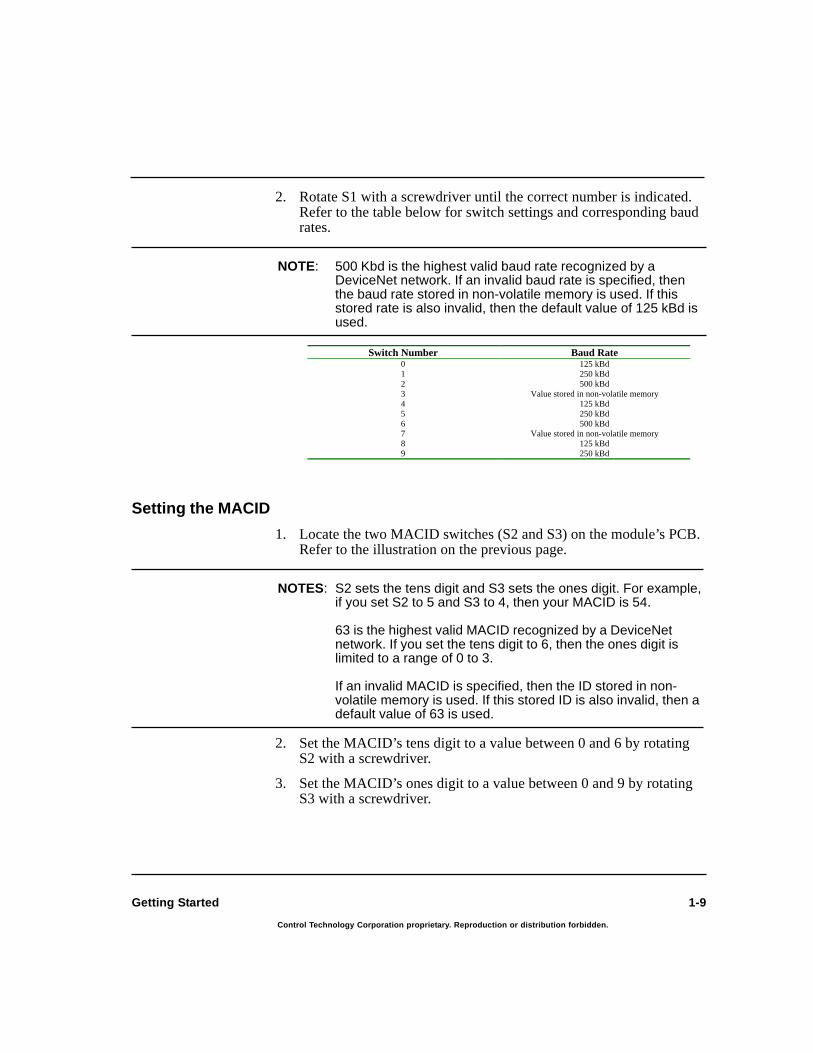
Setting the MACID
1. Locate the two MACID switches (S2 and S3) on the module’s PCB.Refer to the illustration on the previous page.
NOTES: S2 sets the tens digit and S3 sets the ones digit. For example,if you set S2 to 5 and S3 to 4, then your MACID is 54.
63 is the highest valid MACID recognized by a DeviceNetnetwork. If you set the tens digit to 6, then the ones digit islimited to a range of 0 to 3.
If an invalid MACID is specified, then the ID stored in non-volatile memory is used. If this stored ID is also invalid, then adefault value of 63 is used.
2. Set the MACID’s tens digit to a value between 0 and 6 by rotatingS2 with a screwdriver.
3. Set the MACID’s ones digit to a value between 0 and 9 by rotatingS3 with a screwdriver.
2. Rotate S1 with a screwdriver until the correct number is indicated.Refer to the table below for switch settings and corresponding baudrates.
NOTE: 500 Kbd is the highest valid baud rate recognized by aDeviceNet network. If an invalid baud rate is specified, thenthe baud rate stored in non-volatile memory is used. If thisstored rate is also invalid, then the default value of 125 kBd isused.
Switch Number Baud Rate0 125 kBd1 250 kBd2 500 kBd3 Value stored in non-volatile memory4 125 kBd5 250 kBd6 500 kBd7 Value stored in non-volatile memory8 125 kBd9 250 kBd
1-10
Control Technology Corporation proprietary. Reproduction or distribution forbidden.
2716D DeviceNet Module Installation Guide
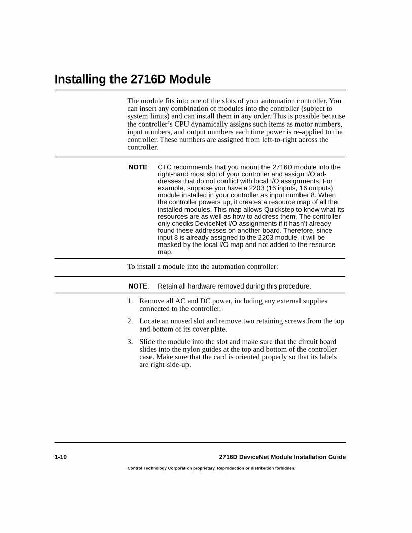
The module fits into one of the slots of your automation controller. Youcan insert any combination of modules into the controller (subject tosystem limits) and can install them in any order. This is possible becausethe controller’s CPU dynamically assigns such items as motor numbers,input numbers, and output numbers each time power is re-applied to thecontroller. These numbers are assigned from left-to-right across thecontroller.
NOTE: CTC recommends that you mount the 2716D module into theright-hand most slot of your controller and assign I/O ad-dresses that do not conflict with local I/O assignments. Forexample, suppose you have a 2203 (16 inputs, 16 outputs)module installed in your controller as input number 8. Whenthe controller powers up, it creates a resource map of all theinstalled modules. This map allows Quickstep to know what itsresources are as well as how to address them. The controlleronly checks DeviceNet I/O assignments if it hasn’t alreadyfound these addresses on another board. Therefore, sinceinput 8 is already assigned to the 2203 module, it will bemasked by the local I/O map and not added to the resourcemap.
To install a module into the automation controller:
NOTE: Retain all hardware removed during this procedure.
1. Remove all AC and DC power, including any external suppliesconnected to the controller.
2. Locate an unused slot and remove two retaining screws from the topand bottom of its cover plate.
3. Slide the module into the slot and make sure that the circuit boardslides into the nylon guides at the top and bottom of the controllercase. Make sure that the card is oriented properly so that its labelsare right-side-up.
Installing the 2716D Module

1-11
Control Technology Corporation proprietary. Reproduction or distribution forbidden.
Getting Started
4. Press the module firmly into the controller. Make sure that themodule’s faceplate is flush with the adjacent sheet metal surface.
5. Re-install two retaining screws in the top and bottom of the newmodule.
DN3
Retaining Screw
Retaining Screw
Shown with the 2716D module installed in the right hand slot
2700 SeriesAutomationController
2701 2203
I/O Supply
Logic Supply
Status
COMM
CPU 16IN/16OUT
1
5
9
13
INPUTS
1
5
9
13
OUTPUTS
NET
MOD
TX
RX
POLL
COS
2716D
COMMS
TAT
US
CO
MM
1C
OM
M2
CO
MM
1
RS
-232
RS
-485

1-12
Control Technology Corporation proprietary. Reproduction or distribution forbidden.
2716D DeviceNet Module Installation Guide
Connecting the 2716D to a Network
After the module is installed in the controller slot, you are ready toconnect it to a DeviceNet network. The illustration below shows atypical DeviceNet network using the 2716D as both a master and a slavedevice.
OperatorInterfacePanel
ServoController
DeviceNetI/O Module
2700 Controllerwith 2716D DeviceNet Master
Host computer with Quickstepsoftware and DeviceNet Configurator software
DN7
NET
MOD
TX
RX
POLL
COS
2700 SeriesAutomation Controller
ControlTechnology Corporation
2701
I/O Supply
Logic Supply
Status
COMM
CPU 16IN/16OUT
2203 2716D
INPUTS
OUTPUTS
STA
TUS
RS
-232
RS
-485
CO
MM
1C
OM
M2
CO
MM
1
COMM
2700 Controllerwith 2716D DeviceNet Slave
2700 SeriesAutomation Controller
ControlTechnology Corporation
2701
I/O Supply
Logic Supply
Status
COMM
CPU 16IN/16OUT
INPUTS
OUTPUTS
2203
NET
MOD
TX
RX
POLL
COS
STA
TUS
RS
-232
RS
-485
CO
MM
1C
OM
M2
CO
MM
1
COMM
2716D

1-13
Control Technology Corporation proprietary. Reproduction or distribution forbidden.
Getting Started
General Setup Information
Before you do any configuration or make any final connections to yournetwork, you should consider the following steps:
1. Install a test DeviceNet network. If this is the first time you haveused certain devices, you will probably want to create a test networkwith at least one of each device. This will allow you to test yourscanner configuration and determine how you will configure eachdevice. Once you have tested each device, you can replicate much ofthe configuration information for additional devices. When estab-lishing your test network, ensure that the physical topology meetsthe DeviceNet specifications, including installation of requiredtermination resistors.
2. Perform operational testing. Initial testing may involve only a fewdevices and a test network. During this phase of testing you willwant to ensure that the scanner is properly connected to the devicesand that the device data is mapped properly. Advanced testing willinclude all nodes on the network. During this phase you will ensurethat network loading and response time meet the application require-ments. Obviously, you will also be testing the application logic andsystem operation.

1-14
Control Technology Corporation proprietary. Reproduction or distribution forbidden.
2716D DeviceNet Module Installation Guide
Configuring Master Devices
This section provides a general overview of the required steps forconnecting a master device such as the 2716D to the DeviceNetnetwork. If the network is more complex or you have sophisticated toolsfor configuring master devices, then some of the steps for configuringmaster devices may already be incorporated into the master device’sconfiguration.
1. Set the baud rate and MACID. For the 2716D, follow the instruc-tions in the DeviceNet Hardware Configuration section in thischapter. For other devices, refer to the device’s documentation.Make sure that the slave device has a unique MACID and that itsbaud rate matches all other devices on the network.
2. Select a software tool to configure your devices. This programspecifies which nodes will be scanned, how the devices will beaccessed, and where DeviceNet data will be mapped within control-ler memory. If you are using the 2716D as the master (scanner)device, you must use our DeviceNet Configurator program. TheDeviceNet Configurator is expressly designed to work with the2716D as a master device and will not work with other masterdevices. For more information, refer to the DeviceNet ConfiguratorUser Guide.
3. Identify the DeviceNet devices that will be on your network. Eachdevice vendor should provide you with information about thedevice’s DeviceNet capabilities. This may take the form of writtendata or an electronic data sheet (.EDS file). You need to know thefollowing device characteristics if you expect to have the 2716D(acting as master) verify them before connecting:
• Device Type - The device type is a number code assigned by theODVA.
• Device Vendor - The device vendor is an ID assigned by theODVA.
• Product Code - The product code, which is assigned by thevendor, is a unique number that specifically identifies a type ormodel of device. For the 2716D, the vendor code is 2716.
Connecting the 2716D to a Network

1-15
Control Technology Corporation proprietary. Reproduction or distribution forbidden.
Getting Started
• Revision Level - This is the revision level for a device’sfirmware.
• Serial Number - This is a product’s serial number, but moreimportantly, the ODVA requires that a product’s serial numberand its device vendor ID be unique. These two numbers are usedduring the duplicate MACID detection routine to make surethere is a way to uniquely identify any device on the busregardless of its MACID setting.
NOTE: Be certain that the .EDS file’s version number or revisionmatches your actual device before using the file. If the revisionnumber is more recent than your physical device, it maycontain parameters that aren’t supported by the device.
4. Choose the master device that will be responsible for sendingconfiguration messages. Some scanners such as the 2716D areequipped to send configuration messages when the system isinitialized. However, other master devices may need to have aseparate network configuration module to send out the messagesthat configure the network for a particular operation or to provideaccess to specific information.
5. Determine the data format (I/O Assembly) that will be used by eachdevice and decide how data will be mapped to the controller. Thedocumentation for each device will indicate the format of the I/Omessages it sends (produces) and receives (consumes). Manydevices will allow you to select among several data formats. Theseselectable formats are called I/O assemblies. The particular I/Oassembly that a device uses is established when the device isconfigured. Locate the required information in the module’sDeviceNet Objects; information may exist in multiple locations.If it exists in an Assembly Object, it always appears in anotherobject.
If you’re using the 2716D as a master, you also need to determineif it can gather data from various locations within the device forsending messages and whether it allows incoming information to bedistributed in the same way. Devices that are capable of extractinginformation from or sending information to any sequence of registersrequire additional configuration. The master also needs to know theformat of the data such as whether it is an 8-bit decimal value or 8digital inputs.

1-16
Control Technology Corporation proprietary. Reproduction or distribution forbidden.
2716D DeviceNet Module Installation Guide
NOTES: Some devices may have various types of I/O modules at-tached to them. The type of module, a module’s physicallocation, and the order in which it is attached to a device areall factors that can affect the format of the data.
Multiple sets of data may be required by different networkfunctions. This includes information needed for normal opera-tion (usually needed by a scanner) as well as any datarequired by any other master devices.
6. Determine the message types (Poll, Bit Strobe, COS/Cyclic) sup-ported by each device that are available to transmit information.Before choosing any specific message types, determine your timingrequirements (scan time) and how often you require updatedinformation.
If you are using the 2716D as a master, you also need to list themessages that are needed to gather information from various slavedevices and to set values in the slave device Objects. Examine eachmessage and determine what parts of the data are needed andwhether to set any remaining data or ignore it.
7. Configure the DeviceNet devices. For each device being used youwill need to set its MACID and baud rate. Every device must have aunique MACID. All baud rates must be the same. Some devices mayuse switches to set these parameters; others will require either aconfiguration program or configuration messages generated by themaster device. Some devices will require additional configuration,such as setting the I/O assemblies used or setting up that device so itproduces the information expected in steps 5 and 6.
If you are using the 2716D as a master device, then you need toprogram the controller that is using the scanner data withconfiguration information specific to that scanner.
NOTE: Other master devices such as human-machine interfaces(HMIs). HMIs require you to program the display of information(graphics, text, colors, etc.) or even to program multiple pagesof information and logs for trend and historical displays formore complex HMIs. Supervisory systems that are used asmasters require acceptable warning and error limits and maypossibly need diagnostic and troubleshooting sequences.
Connecting the 2716D to a Network

1-17
Control Technology Corporation proprietary. Reproduction or distribution forbidden.
Getting Started
8. Select your cabling and power supply. Decide on the number ofnetworks required and the number of nodes on each network. Youneed a separate 2716D module used as a scanner for each networkand there can be multiple 2716D slaves on a single network. Youalso need to connect to each DeviceNet network through theDeviceNet connector on the 2716D’s front panel. Finally, to config-ure the 2716D module, you need a serial cablem (CTC models2880B and 2881 are recommended) to connect to a PC.
9. Set up the I/O messaging channel. Only one master device (usually ascanner) can receive I/O messages, so you must specify a device toreceive this data. If other master devices need access to the sameinformation, they must be capable of using Explicit messages. If not,you can configure the scanner so it transmits information to anothermodule or even another master module that operates as a slave to theI/O configured scanner.
10. Determine your Explicit Messaging requirements. There might beareas on the network that can only be controlled with Explicitmessages.
11. Use the DeviceNet Configurator to specify your Explicit messages.CTC recommends that you only work with one device at a time.Enter the required information for a device and test it on the net-work. If it works properly, save the configuration file and proceedto the next device.
NOTES: The network speed (125, 250 or 500 kBd) and scan time limitthe amount of data you can include in messages for the scan.Cyclic/COS messages may allow the scanner to recognizeinfrequent changes without requiring a return message to themodule during a scan.
You must also allow adequate idle time on the network so thatinfrequent Cyclic/COS messages can be processed along withany other messages needed by other functions on the network(HMI and Supervisory).
12. Download your configuration file to your master device. If you areusing the 2716D as a master, you must use the DeviceNetConfigurator to download the file. Make sure the MACID in yourconfiguration file matches the 2716D’s hardware settings.
1-18
Control Technology Corporation proprietary. Reproduction or distribution forbidden.
2716D DeviceNet Module Installation Guide
Disabling Master ModeTo operate the 2716D as a slave, you need to disable master mode. Youcan accomplish this by downloading information to the 2716D with theDeviceNet Configurator in the following ways:
• Download a file without any slave devices
• Download a file where the MACID is different from the module’shardware settings.
NOTE: Refer to the DeviceNet Configurator User Guide for moreinformation on downloading data and using the Configurator.
Connecting the 2716D to a Network

1-19
Control Technology Corporation proprietary. Reproduction or distribution forbidden.
Getting Started
Configuring Slave Devices
This section provides a general overview of the required steps forconnecting a slave device such as the 2716D to the DeviceNet network.
1. Set the baud rate and MACID. For the 2716D, follow the instruc-tions in the DeviceNet Hardware Configuration section in thischapter. For other devices, refer to the device’s documentation.Make sure that the slave device has a unique MACID and that itsbaud rate matches all other devices on the network.
NOTES: Make sure the 2716D is in slave mode. Refer to DisablingMaster Mode for instructions on disabling master mode andenabling slave mode.
Some devices use switches to set baud rate and MACID;others require either a configuration program or configurationmessages generated by the master device. Some devicesmay require additional configuration, such as setting the I/Oassemblies used.
2. Choose the master device that will be responsible for sendingconfiguration messages. Scanners such as the 2716D are equippedto send configuration messages when the system is initialized.However, other master devices may need to have a separate networkconfiguration module to send out the messages that configure thenetwork for a particular operation or to provide access to specificinformation.
3. Select a software tool to configure your devices. Explicit messagesare used to specify the required register objects (see step 4 below)and scan time of the slave device. If you are using the 2716D as amaster and have a second 2716D as a slave on the same network,you should use CTC’s DeviceNet Configurator program for thispurpose. For more information, refer to the DeviceNet ConfiguratorUser Guide.

1-20
Control Technology Corporation proprietary. Reproduction or distribution forbidden.
2716D DeviceNet Module Installation Guide
NOTES: If you are using the 2716D as a slave, you will need its .EDSfile, which ships with the module and can also be downloadedfrom www.control.com/devicenet. If you are using otherdevices as slaves, you can obtain their EDS files from theODVA at www.odva.org or from the manufacturer of thedevice.
Be certain that the .EDS file’s version number or revisionmatches your actual device before using the file. If therevision number is more recent than your physical device, itmay contain parameters that aren’t supported by the device.
4. Determine the data format (I/O Assembly) used by the slave deviceand decide how data will be mapped to the controller. The documen-tation for each device will indicate the format of the I/O messages itsends (produces) and receives (consumes). Many devices will allowyou to select among several data formats. These selectable formatsare called I/O assemblies. The particular I/O assembly that a deviceuses is established when the device is configured. Locate the re-quired information in the module’s DeviceNet Objects; informationmay exist in multiple locations. If it exists in an Assembly Object, italways appears in another object.
5. Determine the controller registers that will be available to theDeviceNet network. For more information on these registers,refer to Chapter 3, DeviceNet Special Registers.
6. Determine the message types (Poll, Bit Strobe, COS/Cyclic, etc.)supported by your slave device that are available to transmit infor-mation. Before choosing any specific message types, determine yourtiming requirements (scan time) and how often you require updatedinformation.
Connecting the 2716D to a Network
1-21
Control Technology Corporation proprietary. Reproduction or distribution forbidden.
Getting Started
7. Compile the list of messages needed to initialize this configuration.If you are using the 2716D as a slave, this can be as simple as asingle message to set data in the Configuration Assembly Object.Some tools, such as the DeviceNet Configurator, can assist with thisstep by using information in the .eds (electronic data sheet) file or byusing the Configuration Objects included with the device.
8. Choose the controller registers for the 2716D that will be used formessaging. The number of registers used per message affects themessage size. For more information on these registers, refer toChapter 3, DeviceNet Special Registers.
NOTE: For the 2716D slave, you should also consider other commu-nications parameters (such as BOI), time-outs, and I/O con-figuration (default/error states for digital I/O, Analog I/O ranges,and proximity/photo-detector sensitivity). There may also beapplication-specific parameters such as Register and RegisterSet Objects. Some items are automatically set by the masterdevice, are stored in non-volatile memory and set upon initial-ization, or are set during a reset sequence.
9. Select your cabling and power supply. You can have multiple2716D slaves on a single network. You also need to connect to eachDeviceNet network through the DeviceNet connector on the 2716D’sfront panel.

1-22
Control Technology Corporation proprietary. Reproduction or distribution forbidden.
2716D DeviceNet Module Installation Guide
Because of certain DeviceNet limitations such as speed, CTC has thefollowing list of caveats for I/O connections:
NOTES: This section only applies to the 2716D in master mode.
The first item on this list is associated with controller inputfunctions. This causes the controller to monitor the inputs at ahigh rate (1 ms or less) or to check whether it’s necessary toupdate the outputs faster than the normal execution scan time.DeviceNet I/O should not be used because it is not immedi-ately accessible and a significant amount of time (largefraction of a ms) is needed to communicate with the 2716Dmodule to get I/O status.
• Linkable Software Counters 1-8 - Digital inputs that are used tocount pulses or transitions must be local to the controller containingthe 2716D master module. DeviceNet inputs cannot be linked to thecontroller’s internal software counters.
• Programmable Limit Switch (PLS) function - You should not assigna PLS output to the 2716D because the PLS operates at too great aspeed.
• Pulse outputs - Outputs 1 and 2 in each CTC controller arededicated to sending out an automatic stream of pulses with registers5901-5908. These outputs must be located in the controller contain-ing the 2716D master module.
• Software Faults and Register 13009 - Register 13009 is used toautomatically turn off an output when a software fault occurs. Thismeans that if a software fault occurs, the output specified in thisregister will be de-energized.
• Local I/O Assignments and DeviceNet I/O - Be very careful whenyou assign I/O mapping to your DeviceNet I/O. Your I/O assign-ments must not coincide with any local I/O in your controller. CTCrecommends that you mount the 2716D module into the right-handmost slot of your controller and assign I/O numbers that start afterany local I/O assignments. For example, if you have a 2203 16input/16 output module installed on your system and have assignedI/O number 16 to your DeviceNet module, the controller will onlysee the local I/O and will not recognize conflicting I/O numbers onthe 2716D module.
I/O Caveats

1-23
Control Technology Corporation proprietary. Reproduction or distribution forbidden.
Getting Started
• Align digital I/O points in blocks - I/O addressing must be done inblocks of 8 bits, or 1 byte. Each block of 8 inputs or outputs musteither be mapped to a single device or remain unmapped. Forexample, if you map a digital I/O point to address 17, then theremaining 7 bits may not be used for any other device. In addition,mappings must start with an I/O number that is a multiple of 8 plus1 (1,9,17,25, etc.).
• Analog I/O limitations - Analog I/O is not recommended for use withDeviceNet because of resolution and scaling factors. For example,suppose you have an actual analog value of 312 that is representedby a number in the range 0-1,023. The controller and 2716D canscale this number, which seems to provide a greater degree ofprecision such as a number between 1-10,000. If you use 312, theclosest analog value is (312/10,000)*1023=32 (rounded up from31.9). If this number is converted back, you get 313 as a result. Inaddition, if a Quickstep program is checking the actual output valueagainst the stored value to see if they’re the same, it results in anerror. This situation grows worse when the range is large or thenumber of bits is small.

1-24
Control Technology Corporation proprietary. Reproduction or distribution forbidden.
2716D DeviceNet Module Installation Guide
Port Addressing
RS-232 Communications
Each communications port is designed to function independently and isautomatically serviced on an interrupt basis. Quickstep program activitywill in no way cause adverse effects to data integrity. CTC’s communi-cations protocols (DLLs) may be used on any port in the controller froma host computer or intelligent host terminal.
Configuring RS-232 and RS-485 Ports
Both the RS-232 and RS-485 ports may be configured to act as a hostusing currently supported message transmitting and receiving conven-tions. See the register reference list available on CTC’s Web site. Toselect a port for host communications, you must store the port number toregister 12000 before accessing any of the communications registers.The controller’s on-board port is port No. 0. The first and second portsin the controller’s rack are ports 1 and 2. Up to eleven ports are sup-ported by the 2700 controller series.
Example:
[1] Store_Port_Number, Transmit _Row_10, Test_Port ;;; Select the second communications port in the controller. ;;; Send Row 10 of the data table out of the communications port. ;;; Test to see if port is busy. --------------------------------------------------------------------------- <NO CHANGE IN DIGITAL OUTPUTS> --------------------------------------------------------------------------- store 2 to Reg_12000 store 10 to Reg_12001 if Reg_12000=0 goto Next
NOTE: Register 12000 has different meanings when reading andwriting to it.

1-25
Control Technology Corporation proprietary. Reproduction or distribution forbidden.
Getting Started
Computer Based Programming and Communications
RS-232 Protocols
The RS-232 ports on the model 2716D provide a means for downloadingQuickstep programs and data communications support.
The 2716D is equipped with built-in protocols that allow direct com-puter communications with its RS-232 ports. These protocols allow anexternal computer to directly interact with many of the controllersresources such as registers, inputs and outputs, and flags. The CTC 32-bit Data Communications Functions Reference Guide,which is availablein the customer area of our website, describes these protocols. The2716D can also be configured to act as a host to support communica-tions with other external peripherals such as operation interface termi-nals, bar-code readers, printers, and other controllers.
NOTE: Do not connect the module to a telephone line.
RS-232 Connections
Connections to the module’s RS-232 port ismade through a modular jack (labeled COMM1or COMM2) on the module’s front panel. Thisjack carries the receive signal, two grounds, andthe transmit signal for the communicationschannel. The pin connection diagram belowillustrates the wiring of the jack. Only the centerfour conductors of a six or eight conductor jackare used.
A series of standard Control Technology cablesare available for connecting to this jack (see thediagram on the next page). As an alternative,many commonly available telephone cables maybe substituted.
16 5 4 3 2
CT1
1 - Not Used2 - TxD outbound3 - Ground4 - Ground5 - RxD inbound6 - Not Used
Modular JackPin Connections

1-26
Control Technology Corporation proprietary. Reproduction or distribution forbidden.
2716D DeviceNet Module Installation Guide
Connecting to a D-Connector
RS-232 ports on computers are usually configured through 25-pin(DB25) or 9-pin (DB9) D-type connectors. There is a standard forwiring such connectors, which is followed by most PCmanufacturers.
Communications cable:
Model 2881 - 5 feetModel 2882 - 15 feetModel 2883 - 25 feet
Personal computer with RS-232 asynchronous communications board
D-connector to modular jack adapter:
Model 2880A for 25-pin D-connectorsModel 2880B for 9-pin D-connectorsModel 2881 for Quickpanel connections
DN5
Module's RS232 ports
2700 SeriesAutomation Controller
ControlTechnology Corporation
2701
I/O Supply
Logic Supply
Status
COMM
CPU 16IN/16OUT
2203
INPUTS
OUTPUTS
NET
MOD
TX
RX
POLL
COS
2716D
STA
TUS
RS
-232
RS
-485
CO
MM
1C
OM
M2
CO
MM
1
COMM
RS-485 Connections
Connections to the module’s RS-485 port aremade through a modular jack (labeled COMM1) on the module’s front panel (jumper must beset properly). This jack carries the receivesignal and the transmit signal for the communi-cations channel (half duplex communications).The pin connection diagram illustrates thewiring of the jack. Only the center two connec-tors of a six or eight conductor jack are used.
Computer Based Programming and Communications
16 5 4 3 2
CT3
1 - NC2 - NC3 - T/R +4 - T/R -5 - NC6 - NC
Modular JackPin Connections

DeviceNet Technical Overview
Chapter 2
Contents
DeviceNet Concepts 2-2
Advantages 2-2CAN 2-2Features 2-3Theory of Operation 2-3DeviceNet Objects 2-5Messages 2-5Master Device Types 2-6
Software Configuration 2-7
Bus-Off Interrupt (BOI) 2-7Register Objects and Register Set Objects 2-7
Messaging 2-10
I/O Messaging 2-10Explicit Messaging 2-12Message Fragmentation 2-13

2-2
Control Technology Corporation proprietary. Reproduction or distribution forbidden.
2716D DeviceNet Module Installation Guide
DeviceNet ConceptsAdvantages
DeviceNet is a low-cost communications link that connects industrialdevices (such as a CTC controller) to a network and eliminates expen-sive hardwiring. This results in improved communication betweendevices as well as important device-level diagnostics that aren’t easilyaccessible or available through hardwired I/O interfaces. In addition,since DeviceNet is an open network standard, it allows many differenttypes of devices from numerous manufacturers to work together on asingle network.
CAN
DeviceNet is based on a broadcast-oriented, communications protocolcalled CAN (Controller Area Network). This protocol was originallydeveloped for the European automotive market to replace expensivewire harnesses with low-cost network cable. As a result, CAN has a fastresponse time and is highly reliable. Consumer and commercial demandfor CAN was a key factor in lowering the price and increasing theperformance of CAN. With CAN, any node may transmit if the bus isnot busy. If two or more nodes begin transmitting at the same time, themessage with the lowest CAN ID will complete the transmission.DeviceNet adds a layer above CAN that allows logical connections toexist among nodes and defines message formats. A single DeviceNetnode may have up to 64 nodes, each with a unique address (MAC ID).DeviceNet supports baud rates of 125, 250, and 500 KB. As the baudrate increases, the maximum allowable distance of cable between anytwo devices decreases. There is only one baud rate allowed per network,and all devices must operate at the same baud rate. The table below listssome of the major features of DeviceNet.
Feature DescriptionNetwork Size Up to 64 nodes
Network Length Selectable end-to-end network distance varies with speed
Baud Rate Distance
125 Kbps 500 m (1640 ft)
250 Kbps 250 m (820 ft)
500 Kbps 100 m (328 ft)
Data Packets 0-8 bytes
Bus Topology Linear (trunkline/dropline): power and signal on the same network cable
Bus Addressing Peer-to-Peer with Multicast (one-to-many);Multi-Master and Master/Slave special case;polled or change-of-state (exception-based)
System Features Removal and replacement of devices from the network under power

2-3
Control Technology Corporation proprietary. Reproduction or distribution forbidden.
DeviceNet Technical Overview
Features
DeviceNet allows for explicit message connections and I/O messageconnections. Explicit messages are typically used for device configura-tion and diagnostics and are more generic and flexible than I/O mes-sages. I/O messages are used for transferring control information, haveless protocol overhead, and are more efficient than Explicit messages.Most devices use the predefined Master Slave Connection Set messagesfor I/O messaging. This set provides for strobed, polled, change of state,or cyclic transmissions. When a strobed connection is used, the mastersends one strobe message to which all enabled slaves respond. With apolled connection, the master sends individual poll messages to eachdevice and expects a response from each device. Change-of-State orCyclic connections do not require a command from the master. A slavedevice using either a change of state (COS) or Cyclic connection sendsdata when the device detects a change in the monitored value(s). Thesemessages restart the interval timer and are used to prevent rapidlychanging data from generating multiple messages and overloading thenetwork. A slave device with either a cyclic or COS connection sendsdata on a fixed (configurable) time interval and the COS connection willalso send a message if a change in the data is detected before the timeinterval is up.
Theory of Operation
The 2716D module uses a 32-bit processor, which allows operation ofthe DeviceNet network and both serial ports at full rated speed withoutencumbering the controller’s CPU. A shared memory interface allowsthe processor to communicate with the controller. The DeviceNetScanner processor transfers data between the memory interface and theDeviceNet network. Configuration data passed to the DeviceNet Scannerprocessor at startup defines which devices will be accessed, how oftenthey will be scanned, and where each device’s data will be stored in thememory interface.
Scanning CharacteristicsThe DeviceNet scan operates asynchronously with the controller scan.Thus, the 2716D can be reading data from DeviceNet nodes while thecontroller is solving logic. When the controller reads data from themodule, it receives the most recent data that has been read. Because thescans are asynchronous, the DeviceNet scan may be faster or slower thanthe controller scan.

2-4
Control Technology Corporation proprietary. Reproduction or distribution forbidden.
2716D DeviceNet Module Installation Guide
The scanner configuration includes a Scan List, which identifies alldevices that the scanner should scan. When the scanner is started, it willattempt to connect to each device on the Scan List. Upon connecting toeach device, the scanner will obtain identity object attribute data fromthe device and compare this data against user specified values. If theselected attributes match, the scanner will begin I/O communicationswith the device.
The rate at which individual devices are polled is configured by the user.This interval is the elapsed time between the start of one scan and thestart of the following scan. The scanner begins a scan by sending out allstrobe and poll messages defined in the configuration. As devicesanswer, their responses are placed in an input buffer. When all pollshave been sent, the scanner retrieves the responses from the input bufferand maps this data to the I/O as specified in the configuration. Assumingthe scan interval is longer than the time required to perform theseoperations, the module will remain idle until it is time to start the nextscan.
NOTE: You must set the scan time to a value large enough to allow allmessages to be sent and responses processed. If more timeis required to send the polls and process the response thanallotted in the scan time interval, the module will extend thescan long enough to process the responses.
Data MappingThe process of transferring data between DeviceNet messages andcontroller data elements is called data mapping. DeviceNet data iscontained in messages that consist of one or more eight-bit bytes. Thedevice vendor determines the content of the message. The vendor mayuse an ODVA standard data assembly or use a vendor specific format.
For example, assume a proximity sensor transmits one byte of datawhere the first bit contains the Sensor State (on or off) and the secondbit contains the Device Status (OK or Fault). Data maps are used tospecify the controller data elements that will contain the Sensor Stateand the Device Status. Using the DeviceNet Configurator, you can mapthe Sensor State bit to Input 49 and the Device Status bit to Input 50.
DeviceNet Concepts

2-5
Control Technology Corporation proprietary. Reproduction or distribution forbidden.
DeviceNet Technical Overview
DeviceNet Objects
The DeviceNet module provides an inexpensive communications linkbetween the DeviceNet network and a CTC controller. This link is madepossible through a “window” created by the module’s software configu-ration. This configuration is stored in the module’s non-volatile memoryand is retained if the module is reset.
The module has pre-configured DeviceNet “objects” which allow thenetwork devices to gain access to the controller’s registers. Theseobjects are abstract representations of particular components. In thiscase, the objects are specified as CTC Register Objects and CTC Regis-ter Set Objects. Register Objects and Register Set Objects are defined bythe device profile that is resident in the module’s software. There are 5CTC Register Objects and 5 CTC Register Set Objects available on theDeviceNet interface.
Register Set Objects can be configured to select both the start registerand the number of registers required for data transfer. These objectsprovide access of up to a range of 16 registers within a CTC controller.The first three register set objects are used to process Group 2 I/Omessages but are also used for explicit messaging. Setting the number ofregisters (or start register to 0) will change the size of the Poll messageand should be configured before using the messages. Register Objectsare always 1 register wide (32 bits/4 bytes of data), are specified only byregister number, and are available for explicit message access to stan-dard controller registers. The remaining register set objects and allregister objects are set to an idle state when the system is initialized.
NOTE: Refer to the Software Configuration section for more informa-tion on register objects, register set objects, and specificDeviceNet parameters.
Messages
All interactions between Master and Slave devices are based on mes-sages. There are two basic message types: I/O messages and explicitmessages. I/O messages provide dedicated, special-purpose communica-tions between a producing application and one or more consumingapplications. Explicit messages provide generic, multi-purpose commu-nication paths between two devices and are used to perform a particulartask and report the results of performing the task. For more informationon message types, refer to Messaging.

2-6
Control Technology Corporation proprietary. Reproduction or distribution forbidden.
2716D DeviceNet Module Installation Guide
Master Device Types
Master devices establish connections on the network and are responsiblefor controlling the data sent over a connection. They are capable ofacting as masters on one connection and slaves on a different connec-tion.
ScannersScanners continuously scan the network to receive data from inputs onmultiple slave devices and make this information available to a control-ler such as a PLC or a computer running dedicated control software. Thecontroller uses this information to update its output values and transmitsthis information to the scanner. The scanner then sends the data tovarious slave devices. Scanners generally have a fixed set of messagesand devices that are monitored and updated within a fixed period (thescan time). Most scanners use I/O messaging.
Human-Machine InterfaceA Human-Machine Interface (HMI) is any way that you interact with asystem. This interface may include simple pushbuttons, switches, lights,and any text or graphical display (such as a touchscreen).
HMIs monitor data in multiple slave devices and use this information todetermine what you see on a display. The HMI may also use inputs thatyou enter to update data in slave devices. However, the HMI does notnecessarily communicate with all devices at any one time and may onlycommunicate with devices whose I/O is currently displayed. The inter-face may contain a subset of the system inputs that are continuouslymonitored, but it usually doesn’t update all its I/O data during a fixedcycle. Although an HMI can use I/O messaging, it usually employsExplicit Messaging Services.
SupervisorsSupervisory systems monitor specific data in some slave devices and arecapable of receiving or setting specific data during troubleshooting.Supervisors do not have to be active on a continual basis. These devicescan remain idle until a problem occurs and may only be needed whenstarting the network.
The supervisor provides additional ways to inspect and evaluate thestatus of individual devices on the network. The data it transmits andreceives depends on the state of operation. For example, supervisorsmight be used to configure machines for different operations in situa-tions where the supervisor has greater storage capacity than a controller.Supervisors can also track operations and make historical data availableto outside systems. In general, supervisors use Explicit Messaging.
DeviceNet Concepts

2-7
Control Technology Corporation proprietary. Reproduction or distribution forbidden.
DeviceNet Technical Overview
Software ConfigurationThis section describes parameters that are stored in volatile memory andcan only be set by software.
Bus-Off Interrupt (BOI)
This action corresponds to an interrupt state that disables the DeviceNetinterface because of continuous streams of corrupted data. Data can becorrupted by large amounts of noise on the line, electronics/wiringproblems, and connecting or disconnecting network devices whilethey’re transmitting.
A value of 0 causes the module to disconnect itself from the networkuntil the system is reset. A value of 1 causes the module to automaticallyreset the interface and attempt to re-establish bus communications. Theparameter’s default value is 0, but you can change this value by writingto the BOI Action Attribute of the DeviceNet Object (Object code 3,Instance 1, Attribute 3).
Register Objects and Register Set Objects
This section describes the various objects residing in the 2716D module.
Poll/Change of State (COS)/Cyclic Response Output DataStart RegisterThis is the start register in the first CTC Register Set Object (Objectcode 80, Instance 1, Attribute 1). It is the first register whose data istransmitted in response to a Poll I/O command or a COS/Cyclic I/Omessage. The module also monitors this data when a COS connection isestablished so that a message is sent when a change of state is detected.
You can set this parameter to any value between 0 and 32,767. A valueof 0 indicates that no register number is required. If this state occurs,then the response to a Poll/COS message contains no data. All othervalues, including invalid register numbers, are passed through themodule to the CTC controller. This parameter’s default value is 10001with the first 32 digital outputs grouped as a 32-bit value.
Poll/COS/Cyclic Response Output Data Number of RegistersThis parameter specifies the number of registers in the first CTC Regis-ter Object (Object code 80, Instance 1, Attribute 2). The module trans-mits information from these registers in response to a Poll I/O commandor a COS/Cyclic I/O message.

2-8
Control Technology Corporation proprietary. Reproduction or distribution forbidden.
2716D DeviceNet Module Installation Guide
You can set this parameter to any number between 0 and 16. A value of 0indicates that no data is available. The physical size of the data is 4times larger than the specified parameter (4 data bytes per register).Therefore, if the specified value is greater than 2, then data cannot besent in a single message packet and a fragmented message protocol isrequired. If the Poll/COS/Cyclic data start register attribute has notchanged, then the number of registers attribute defaults to 2, whichallows access to the first 64 digital outputs.
Poll Command Input Data Start RegisterThis is the start register in the second CTC Register Set Object (Objectcode 80, Instance 2, Attribute 1) and is the first register that gets updatedwhen the module receives data from a Poll I/O command. The modulealso monitors this data when a poll connection is established, whichallows it to detect when the CTC controller makes changes to the data.
NOTE: If new data is received while the controller is trying to updateexisting data, then a software conflict may occur.
You can set this parameter to any value between 0 and 32,767. A valueof 0 indicates that a register number is not required, while all othervalues, including invalid register numbers, are transferred to the CTCcontroller. The default value is 11001, with the first 32 digital inputsgrouped as a 32-bit value.
Poll Command Input Data Number of RegistersThis parameter specifies the number of registers in the second CTCRegister Object (Object code 80, Instance 2, Attribute 2) which areupdated when data is received from a Poll I/O command.
You can set this parameter to any number between 0 and 16. A value of 0indicates that no data is available. If the Poll command data start registerattribute has not changed, then the number of registers attribute defaultsto 2, which allows access to the first 64 digital outputs. If you specify anumber larger than 2, then data is not sent in a single packet and frag-mented message protocol is required. This occurs because the physicalsize of data is 4 times greater than the specified value (4 data bytes perregister).
NOTE: If the module receives a Poll message with either insufficientor additional data, then the controller registers are not up-dated.
Software Configuration

2-9
Control Technology Corporation proprietary. Reproduction or distribution forbidden.
DeviceNet Technical Overview
Bit Strobe Response Data Start RegisterThis parameter is the start register in the third CTC Register Set Object(Object code 80, Instance 3, Attribute 1). This is the first register that istransmitted in response to a Bit Strobe I/O message whose device MACID bit is set to 1.
You can set this parameter to any value between 0 and 32,767. A valueof 0 indicates that a register is not required, while all other values,including invalid register numbers, are transferred to the CTC controller.The default value is 11001, with the first 32 digital inputs grouped as a32-bit value.
Bit Strobe Response Data Number of RegistersThis parameter specifies the number of registers in the third CTCRegister Set Object (Object code 80, Instance 3, Attribute 2) which aretransmitted in response to a Bit Strobe I/O message whose deviceMACID bit is set to 1.
The parameter value is constrained to a number between 0 and 2 becauseof the restriction on the size of Bit Strobe data. A value of 0 indicatesthat no data is available. Although the physical size of the data is 4 timesgreater than the parameter value (4 data bytes per register), the bit stroberestriction of 2 registers allows the data to be sent in single messagepackets. If the bit strobe data start register attribute has not changed,then the number of registers attribute defaults to 2, which allows accessto the first 64 digital inputs.
Register Request TimingThe module continuously requests updated register information from thecontroller so that current data is available to the DeviceNet network.This situation places an additional burden on the controller. The RegisterRequest Timing parameter alleviates this problem by specifying aminimum delay (in ms) between each register value inquiry. If controllerand module traffic is unusually high, then the update cycle might belonger than the specified delay.
It is part of the class instance in both the CTC Register Object class andthe CTC Register Set Object class (Object codes 80 and 81, Instance 0.Attribute 3). You can set this parameter to a value between 0 and 20,000(20 seconds) with a default value of 20 ms.

2-10
Control Technology Corporation proprietary. Reproduction or distribution forbidden.
2716D DeviceNet Module Installation Guide
MessagingThis section describes the advantages and disadvantages of usingdifferent message types.
I/O Messaging
I/O messages consist of a small set of messages that may contain a fixedamount of data. For example, Bit-Strobe messages can only transmit onebit of data from a master to a slave device and can only receive 8 bytes(64 bits) of data from each slave. Poll messages are used to send andreceive significant amounts of data between masters and slaves and areonly limited by bandwidth constraints. Cyclic/COS messages are alsoused to transmit large amounts of data from slaves to masters when datachanges or at regular intervals.
I/O messages have low overhead. Messages of 8 bytes or less have nocommunications overhead. Larger packets are less efficient because theyrequire one byte of overhead plus an extra message packet for every 7data bytes. For example, if you have 8 data bytes or less, the message isnot fragmented and only requires the usual CAN header and trailer.However, if you are sending 9 bytes of data, then the message is frag-mented and an additional fragmentation protocol byte must be includedin the first CAN message, which only leaves room for 7 data bytes. Theremaining 2 data bytes require a 2nd CAN message with a CAN header,CAN trailer, and an additional fragmentation byte. Therefore, it takes 3additional bytes to complete a 9-byte message. Although longer mes-sages have a smaller percentage of overhead, they still consume networkbandwidth.
NOTE: For more information on fragmented messages, refer to theMessage Fragmentation section.
If you’re using a more complex device with configurable I/O, you mightbe able to change the message contents when I/O is added, but themessage data structure is still determined by the manufacturer. Forexample, for the 2716D, you are able to configure the message size andmessage contents, but the message length must be a multiple of 4 bytesand cannot exceed 64 bytes.
I/O messages are also Group 2 messages, and the DeviceNet specifica-tion states that a device is limited to only one Group 2 connection.Therefore, the device is only allowed to exchange I/O messages with asingle master device. This means that if you use I/O messaging with ascanner on your network, then HMIs and Supervisory masters are notallowed to communicate using I/O messaging with any of the nodes

2-11
Control Technology Corporation proprietary. Reproduction or distribution forbidden.
DeviceNet Technical Overview
being scanned with I/O messaging. These master devices are allowed touse Explicit messaging if a device supports UCMM.
The various types of I/O messages are described in the following para-graphs.
Bit-Strobe MessageBit-Strobe commands can rapidly transmit small amounts of data be-tween a master and its bit-strobed slaves. Because of the need to send/receive data quickly, the command response messages are limited to 64bits (8 bytes) in length. Each bit corresponds to a MACID (0-63) sup-ported on the network. Although the master device transmits all 64 bits,the network does not have to contain 64 devices. In addition, the mes-sage is only “consumed” by devices that are configured for Bit/Strobemessages from that particular master device. You can configure slavedevices to either ignore the Bit-Strobe command, consume the commandand its output data, or consume the command and use it to trigger aresponse. Commands are ignored until a bit-strobe connection is estab-lished. The master then uses the connection to update data on the slavedevice and to receive data from the slave in the response (if configured).
Poll MessagePoll commands can move any amount of I/O data between a master andits polled slaves and back again if required. Unlike the Bit-Strobecommand, which broadcasts its message to the entire network, the Pollcommand is directed to one specific slave device. You can configure theslave device to either ignore the poll command and its output data orconsume the command and use it to trigger a poll response. Poll com-mands, like Bit-Strobe commands, are also used by the master to updatedata on the slave device and to receive data from the slave in response.
Change of State/Cyclic MessageCyclic/COS messages are used for slave-to-master transmission and arenot in response to a request from the master. Although this message canconsist of unlimited amounts of I/O data that is directed towards asingle, master device, maximum message size and message content maybe limited by the design of your device. In many cases, these itemscannot be altered because some manufacturers of simple devices withfixed I/O have pre-set the contents of messages as well as messagelength.

2-12
Control Technology Corporation proprietary. Reproduction or distribution forbidden.
2716D DeviceNet Module Installation Guide
Both COS and Cyclic messages can send messages at a fixed(configurable) time interval as well as when data has changed. Whendata changes and messages are sent out, the interval timer is restarted,which determines the maximum time between COS messages. Toprevent rapid data changes from overloading the network, the COSconnection allows you to define a second interval. This interval preventsthe device from sending additional messages before the productioninhibit timer has elapsed. This also allows you to define the minimumtime between COS messages and also ignores changes to the data duringthis time. When you establish a connection to the network, you canconfigure the module to automatically send the next message without anacknowledgment or you can postpone sending another message until themodule receives an acknowledgment from the master device.
COS/Cyclic messages can also be combined with a Poll message to senddata in response to scanner requests, at specified intervals, or when thedata changes. The response to the Poll command will also re-start theinterval timer mentioned above.
Explicit Messaging
Explicit messages allow a master device to retrieve and even change anyof the DeviceNet objects within a module. The master also has access toall the data on the DeviceNet network and can issue commands to amodule and its subsystems. However, these advantages place additionaloverhead on the message such as specifying the operation requested andthe required objects in the module for this operation. Explicit messagingmay also be provided by using UCMM services, which allow multipleconnections to any module. The maximum number of connections andnumber of operations depend on the module’s implementation. Thisinformation is provided with the module’s specifications or with thestatement of compliance.
Another disadvantage of using Explicit messaging is that data is limitedto the data in a particular object. If the required data does not residewithin a single object, then multiple messages are needed to gather thedata. Although it may be possible to avoid this problem by definingadditional objects (Dynamic Assemblies) in your setup that are a collec-tion of data from several objects within the system, this type of assemblyobject is not widely supported by most devices.
Messaging

2-13
Control Technology Corporation proprietary. Reproduction or distribution forbidden.
DeviceNet Technical Overview
Message Fragmentation
This section compares I/O and Explicit message fragmentation services.
Protocol ByteThe protocol byte is a message header that is only used in the explicitmessage fragmented data field format. It is not used with I/O messagefragmentation. The protocol byte is structured as illustrated below and asdescribed in the following paragraphs.
Message Header (Protocol Byte)
7 6 5 4 3 2 1 0
Fragmentation Bit
Transaction ID (XID) MACID
DN9
Bit 7 indicates whether a message is fragmented. If this bit is set to 1,then the message is fragmented and the message header will be followedby a fragmentation protocol byte, which is discussed later in this section.
Bit 6 is the transaction ID, or XID. This ID is used to match up a mes-sage response with its original command message. For example, supposeyou send out two messages to a device and receive a single reply.Without the XID, there’s no way of knowing which message correspondsto the response. The XID bit is turned on and off as each message istransmitted. The first has an XID of 0 and the second has an XID of 1.This makes it easy to pair a message with its response. The XID is onebit in length and has only two states, so it is only used for a maximum of2 messages at a time. This feature is useful for master devices where thetimeout setting is smaller than the response time. The remaining 6 bits ofthe protocol byte correspond to a device’s MACID. This protocol byte isrepeated for all fragments of the message.
Fragmentation Protocol ByteBoth explicit messages and I/O messages contain a fragmentation bytethat consists of a start, middle, or end fragment. The lower 6 bits is thesequence number. Sequence numbers are the fragment numbers within amessage. The fragment number starts with 0 and increases with eachfragment, which ensures that no fragments are lost or repeated.

2-14
Control Technology Corporation proprietary. Reproduction or distribution forbidden.
2716D DeviceNet Module Installation Guide
For explicit messages, the message recipient must acknowledge eachmessage fragment before the next fragment is transmitted. This ac-knowledgment message sets both high bits to 1 and returns the sequencenumber in the lower 6 bits. If no acknowledgment is received within thefragment time-out, then the fragment is resent.
For I/O messages, there is no acknowledgment received for fragmentedmessages, so each fragment is sent only once. The time-out for I/Omessages is based on a complete message being received, so if a frag-ment is lost, the entire message is treated as lost and the transactionshould time out.
Additional BytesThe next byte in the message is the service code. The three most usefulcodes are Read Single Attribute (0EH), Write Single Attribute (10H),and Reset (05H). In the response, if the most significant bit is set, thenthe service was successful. If the service failed, then the error responsehas a special service code that indicates this.
Service codes are followed by object, instance, and attribute numbers.Objects and instances are either 8 or 16 bits and are dependent on thetype of connection. 16-bit values are structured with the low bytefollowed by the high byte.
Write commands are sequenced so that the data follows the object,instance, and attribute information. Reset commands may not require theattribute although attributes can be used to specify the type of reset.
Messaging

2-15
Control Technology Corporation proprietary. Reproduction or distribution forbidden.
DeviceNet Technical Overview
Message OverheadMessage fragmentation services are used when messages exceed 8 bytesin length. The fragmented data field formats for I/O and Explicit messag-ing are shown below.
Application I/O Data
I/O Message Format
Data Field(0.....8 bytes)
CANHeader
CANTrailer
7 6 5 4 3 2 1 0
Fragmentation Protocol
ByteOffset
0
MessageBody
Fragment
1...7
7 6 5 4 3 2 1 0Byte
Offset
0.....7
MessageBody
Non-Fragmented I/O Data Field Format
Fragmented I/O Data Field Format
DN8
Protocol Fields&
Service Specific Data
Explicit Message Format
Data Field(0.....8 bytes)
CANHeader
CANTrailer
7 6 5 4 3 2 1 0
Fragmentation Protocol
ByteOffset
0
MessageBody
Fragment
7 6 5 4 3 2 1 0Byte
Offset
MessageBody
Non-Fragmented Explicit Data Field Format
Fragmented Explicit Data Field Format
Message Header0
1...7
Message Header
1
2..7

2-16
Control Technology Corporation proprietary. Reproduction or distribution forbidden.
2716D DeviceNet Module Installation Guide
You may notice that the Explicit message data field contains an extraprotocol byte. This results in additional overhead and means that explicitmessage fragments only contain 6 data bytes while I/O message frag-ments contain 7 data bytes. Explicit messages carry even more overheadbecause they require an acknowledgment for each message fragment;I/O messages do not.
Each fragment, or CAN message, contains up to a maximum of 8 bytesof data but may also contain as little as 0 bytes. DeviceNet does notallow for 0 byte fragments because of the requirement for a fragmenta-tion protocol byte. The very last message fragment has at least 2 bytes:the fragmentation protocol byte and the data byte that forced the mes-sage to splinter.
NOTE: 0 byte non-fragmented messages are permitted.
A single CAN packet without data consists of a CAN header that in-cludes the CAN message ID, the checksum, and the trailer. The headercontains 19 bits of data, of which 11 are assigned to the message ID, andthe trailer contains 28 data bits. Therefore, the total CAN overhead is 47bits.
All this overhead means that an 8 byte message contains a total of 111bits (47 CAN bits + 64 data bits). If we assume that we are using thefastest 500 kBd baud rate and each bit requires 2 µS to transmit, then thetotal transmission time is 222 µS. If you are at 125 kBd, then the totaltime is 888 µS.
Messaging

2-17
Control Technology Corporation proprietary. Reproduction or distribution forbidden.
DeviceNet Technical Overview
If we change the I/O message to 9 data bytes, then fragmentation ser-vices are required and the overhead accumulates. You might think thatthe 1st data packet contains all 8 data bytes, but in reality, the 8th databyte is shifted to the second packet because the first packet now requiresa fragmentation protocol byte.
The second data packet consists of the CAN header and CAN trailer plusthe fragmentation protocol byte, 8th data byte, and 9th data byte. Fromthe previous example, we know that the CAN overhead is 47 data bits.So, if you add the protocol byte and the two data bytes, you get a total of71 bits (47 + 24). The transmission time for the second packet is 142 µS(71 x 2 µS/bit). If you add this to the 222 µS for the first packet, youhave a total transmission time of 364 µS for both packets. The percent-age of overhead decreases with increasing message size but is stillsignificant.
For explicit messages, even non-fragmented messages contain a messageheader in the first data packet, so only 7 data bytes are allowed. Onceyou need 8 data bytes, fragmentation services are required. The secondfragment has 4 bytes, and only 2 of these are data bytes. These 4 bytesare the message header (protocol byte), fragmentation protocol byte, 7thdata byte (pushed out of the first packet by the addition of a fragmenta-tion byte), plus the 8th data byte. The fragment is 79 bits and has atransmission time of 158 µS. Each fragment also requires an acknowl-edgment, so this adds 2 acknowledgment messages that are 3 bytes inlength.
As you can see, with either type of messaging, adding even one addi-tional data byte places considerable overhead on the DeviceNet network.

2-18
Control Technology Corporation proprietary. Reproduction or distribution forbidden.
2716D DeviceNet Module Installation Guide

DeviceNet Special Registers
Chapter 3
Contents
13250-13399 Data Registers 3-2
13400-13463 Individual Module Status and Retry Time 3-2
13464-13465 Scanner and Module Status 3-5
13466-13469 Digital I/O and Analog I/O Status 3-6
13480-13482 Scanner/Baud Rate/Configuration Switch 3-6
13483,13490 Serial Number/Software (Firmware) Version 3-7
13491-13496 Start/Register Count 3-7
13499 Update Cycle - Slave Mode 3-7
13500-13589 Explicit Messages - General Purpose 3-8
13590 Module ID for Explicit Messaging 3-8
13591 Message Number, Register Status 3-8
13592 Requested/Actual Explicit Message Format 3-8
13593 Data Index Register 3-8
13594-13596 Service Code/Class ID/Instance Value 3-9
13597-13598 Selected Data - Signed Byte/Word 3-10
13599 Selected Data - Signed Long Integer 3-10
Using DeviceNet Special Registers 3-10

3-2
Control Technology Corporation proprietary. Reproduction or distribution forbidden.
2716D DeviceNet Module Installation Guide
DeviceNet Special RegistersThe 2716D uses registers 13400 to 13599 for DeviceNet operations.These registers operate as follows:
13250-13399 I/O Data Registers-R/W
These registers provide access to specific sections of an I/O messagethat can vary from 1-32 bits in length. The DeviceNet Configurator hasan I/O mapping feature that allows you to specify register reads andwrites and determines how 13250-13399 are used.
Register reads are mapped as inputs and register writes are mapped asoutputs. Any data stored in a read register is overwritten when the2716D receives its next I/O message. Unmapped registers are undefinedand return a value of -1. Older versions of CTCMon interpret a -1 as anonexistent register and display this value as an asterisk (*). Mappedregisters with nonfunctioning connections return a value of 0.
13400-13463 Individual Module Status and Retry Time - R/W
NOTES: Each hexadecimal digit is equivalent to 4 bits.
Quickstep does not handle hexadecimal numbers. Therefore,decimal equivalents are provided for registers 13400-13463and register 13464.
2700 series controllers must have firmware v2.20 or later todirectly access the DeviceNet special registers from Quick-step. However, if your firmware is an earlier version thanv2.20, you can still access these registers for configuration byconnecting to one of the 2716D’s serial ports with CTCMon.This allows you to read and change (if possible) the registersfrom CTCMon.
The upper 16 bits are used for individual module status and the lower 16bits are used for retry time (read). Scanner Retry Time (Write) value isin seconds and a write of 0 will immediately retry once if there is anerror. The table on the next page lists these values in hexadecimalnotation and provides decimal equivalents for your convenience.

3-3
Control Technology Corporation proprietary. Reproduction or distribution forbidden.
DeviceNet Special Registers
High Bits
Hexadecimal
Notation
Decimal Equivalent Module Status
Upper 16 Bits
0x00010000 65536 Poll connection configuredcorrectly
0x00020000 131072 Bit strobe connectionconfigured correctly
0x00040000 262144 COS/Cyclic connectionconfigured correctly
0x00080000 524288 Explicit connectionconfigured correctly
0x00100000 1048576 Poll timeout detected
0x00200000 2097152 Bit strobe timeout detected
0x00400000 4194304 COS/Cyclic timeoutdetected
0x00800000 8388608 Explicit timeout detected
0x01000000 16777216 Module defined
0x02000000 33554432 Module configured
0x04000000 67108864 Reserved for future use
0x08000000 134217728 Reserved for future use
0x10000000 268435456 Module connection or I/Oaccess failure
0x20000000 536870912 Reserved for future use
0x40000000 1073741824 I/O mapping failure
0x80000000 2147483648 Module failure
The following Quickstep example fetches the retry time:
[1] Get_Retry_Time
;;; This statement extracts the retry time for module MACID 1 ;;; from the module status register. The retry time will be left in ;;; the Status_1 general purpose register. --------------------------------------------------------------------------- <NO CHANGE IN DIGITAL OUTPUTS> --------------------------------------------------------------------------- store Mod_1_Status_R13401 and 65535 to Status_1 ....Other Quickstep statements....
This next Quickstep example checks on whether a module is configuredand also checks for software faults:
[1] Check_Module_Configuration
;;; These statements extract the Module Configured flag for;;; module MACID 1 from the module status register and;;; check if the Module has been configured. If the module has;;; been configured, then the program will continue with the step;;; labeled Module_1_Configured. There should be other statements;;; to handle the state when the Module is not Configured.
---------------------------------------------------------------------------

3-4
Control Technology Corporation proprietary. Reproduction or distribution forbidden.
2716D DeviceNet Module Installation Guide
<NO CHANGE IN DIGITAL OUTPUTS> --------------------------------------------------------------------------- store Mod_1_Status_R13401 and 33554432 to Status_1 if Status_1=33554432 goto Module_1_Configured....Other Quickstep statements....
[2] Check_for_Software_Faults;;; These statements extract the Module Fault flag for;;; module MACID 1 from the module status register and check;;; if there are any errors in the Module operation. If there has been;;; an error with the module, then the program will continue with the;;; step labeled Module_1_Fault. There may be other statements to;;; handle the state when the Module is operating properly or to check;;; for faults in other modules.
--------------------------------------------------------------------------- <NO CHANGE IN DIGITAL OUTPUTS> --------------------------------------------------------------------------- store Mod_1_Status_R13401 and 2147483648 to Status_1 if Status_1=2147483648 goto Module_1_Configured....Other Quickstep statements....
[3] Module_1_Configured --------------------------------------------------------------------------- <NO CHANGE IN DIGITAL OUTPUTS> ---------------------------------------------------------------------------
DeviceNet Special Registers
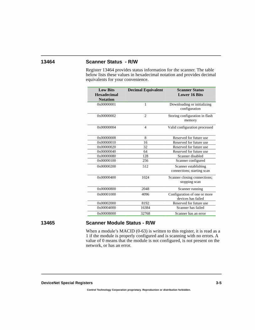
3-5
Control Technology Corporation proprietary. Reproduction or distribution forbidden.
DeviceNet Special Registers
13464 Scanner Status - R/W
Register 13464 provides status information for the scanner. The tablebelow lists these values in hexadecimal notation and provides decimalequivalents for your convenience.
13465 Scanner Module Status - R/W
When a module’s MACID (0-63) is written to this register, it is read as a1 if the module is properly configured and is scanning with no errors. Avalue of 0 means that the module is not configured, is not present on thenetwork, or has an error.
Low Bits
Hexadecimal
Notation
Decimal Equivalent Scanner Status
Lower 16 Bits
0x00000001 1 Downloading or initializingconfiguration
0x00000002 2 Storing configuration in flashmemory
0x00000004 4 Valid configuration processed
0x00000008 8 Reserved for future use
0x00000010 16 Reserved for future use
0x00000020 32 Reserved for future use
0x00000040 64 Reserved for future use
0x00000080 128 Scanner disabled
0x00000100 256 Scanner configured
0x00000200 512 Scanner establishingconnections; starting scan
0x00000400 1024 Scanner closing connections;stopping scan
0x00000800 2048 Scanner running
0x00001000 4096 Configuration of one or moredevices has failed
0x00002000 8192 Reserved for future use
0x00004000 16384 Scanner has failed
0x00008000 32768 Scanner has an error
3-6
Control Technology Corporation proprietary. Reproduction or distribution forbidden.
2716D DeviceNet Module Installation Guide
13466 Digital Input Status - R/W
When a digital input number from 1-1024 is written to this register, it isread as a 1 if digital input data is valid and as a 0 if the data is invalid.Data is valid when the input is configured as a DeviceNet input. Inaddition, the connection in use must be active with no errors (data isbeing updated).
13467 Digital Output Status - R/W
When a digital output number from 1-1024 is written to this register, it isread as a 1 if digital output data is valid and as a 0 if the data is invalid.Data is valid when the output is configured as a DeviceNet output. Inaddition, the connection in use must be active with no errors (data isbeing updated).
13468 Analog Input Status - R/W
When an analog input number from 1-128 is written to this register, it isread as a 1 if analog input data is valid and as a 0 if the data is invalid.Data is valid when the input is configured as a DeviceNet input. Inaddition, the connection in use must be active with no errors (data isbeing updated).
13469 Analog Output Status - R/W
When an analog output number from 1-128 is written to this register, itis read as a 1 if analog output data is valid and as a 0 if the data isinvalid. Data is valid when the input is configured as a DeviceNetoutput. In addition, the connection in use must be active with no errors(data is being updated).
13480 Scanner MACID - Read Only
This register is used to list the current active DeviceNet setting of thescanner’s MACID.
13481 Scanner Baud Rate - Read Only
This register is used to specify the current active DeviceNet setting ofthe scanner’s baud rate. 0=125kBd, 1=250kBd, 2=500kBd.
13482 Configuration Switch - Read Only
This register stores the configuration switch settings.The MACID isstored in the lower 8 bits and the baud rate is stored in the next byte.
DeviceNet Special Registers

3-7
Control Technology Corporation proprietary. Reproduction or distribution forbidden.
DeviceNet Special Registers
13483 Serial Number - Read Only
This register stores the module’s serial number.
13490 Software (Firmware) Version - Read Only
This register lists the software (firmware) version. The format is majorrevision * 100 + minor revision.
NOTE: For more information on registers 13491-13496, refer to theSoftware Configuration section in Chapter 2, DeviceNetTechnical Overview.
13491 Start Register - Bit Strobe Slave Response
This register stores the starting register number for the bit strobe slaveresponse.
13492 Register Count - Bit Strobe Slave Response
This register stores the register count for the bit strobe slave response.
13493 Start Register - Poll/COS Slave Response - R/W
This register stores the starting register number for the poll/COS slaveresponse.
13494 Register Count - Poll/COS Slave Response - R/W
This register stores the register count for the poll/COS slave response.
13495 Start Register - Poll Slave Input - R/W
This register stores the starting register number for the poll slave inputmessage.
13496 Register Count - Poll Slave Input (Slave Mode) - R/W
This register stores the register count for the poll slave input message.
13499 Update Cycle (ms) for Slave Mode, 0=Disable Slave
This register stores the update cycle time (in milliseconds) or scan ratefor the slave registers 13491-13496. A value of zero disables slave mode.

3-8
Control Technology Corporation proprietary. Reproduction or distribution forbidden.
2716D DeviceNet Module Installation Guide
13500-13589 Data Registers for Explicit Messages/General Purpose
These registers are used for data storage, the source of data to be in-cluded in explicit messages to various DeviceNet devices, or in re-sponses to these explicit messages.
13590 Module ID for Explicit Messaging
This register stores the module ID number for explicit messaging.
13591 Message Number and Register Status - R/W
In write mode, this register writes out the message number to send. Inread mode, it lists the register status: 0 = Idle, < 0 = Busy, 1 to 254 =Number of bytes Response Received (including protocol and servicecode bytes). If there is no connection, it will read as 255. This register iscleared by a write to 13591, which sends a new message.
13592 Requested and Actual Explicit Message Format - R/W
Write mode sets the requested explicit message format (0=8/8, 1=8/16,2=16/16, 3=16/8). This format specifies the byte length for class IDs andinstance IDs. For example, 8/8 indicates that the class ID is one bytelong and the instance ID is one byte long. Setting this value will estab-lish a connection if there was not one defined for that module. If theconnection exists and the value is different, then a range error will bereturned. Read mode sets the actual message format in low byte, bit 8 =1 when a link is established. If there is no connection, it will read as 255.
13593 Data Index for Registers 13594 to 13599
Register 13593 functions as an index, or pointer, that works in conjunc-tion with the controller’s buffer. The buffer is a region in memory thattemporarily stores the contents of an Explicit Message as it goes out to adevice or when it’s received from a device. Controller registers are thenused to provide easy Quickstep access to the data.
This register is capable of selecting the buffer location for data. Separateregisters (13597-13599) are then provided so Quickstep can accessvarious types of data available in the buffer. If you write data to registers13594-13599, the index register will change its value accordingly. Forregisters 13597-13599, data access is relative to the start of the bufferand is based on the value stored in register 13593. For example, if youwant to write data to register 13597, data is written as a single byte atthe buffer location specified in 13593, then 1 is added to the existingregister value. For registers 13598 and 13599, 2 and 4 are added to the
DeviceNet Special Registers

3-9
Control Technology Corporation proprietary. Reproduction or distribution forbidden.
DeviceNet Special Registers
register value, which corresponds to byte lengths of 2 and 4 bytes. Forother registers, the index is set to the appropriate value. If you want toread the contents of a register, then 13593 is not affected. If no connec-tion exists, then attempts to access this register results in an error.
When dealing with registers 13594-13596, the index register behavesdifferently. The first byte of the message (Index = 0) is the DeviceNetprotocol header byte and will be overwritten by the appropriate datawhen transmitting a message. The next byte is the service code, followedby the DeviceNet Object Class (1 byte when the message format is 8/8and 8/16 or 2 bytes when the format is 16/8 or 16/16). The next 1 or 2bytes are the DeviceNet Object Instance (1 byte for 8/8 and 16/8 for-mats, 2 for 8/16 and 16/16) followed by a 1 byte Attribute number,followed by the data. For the response, the service code will be in thesecond byte (Index = 1) and the response data will start in the third byte.
NOTE: Although registers 13594-13596 are specifically designed tohandle service codes, class IDs, and instance values, you canalso use registers 13597-13599. However, if you use 13597-13599, you need to check the connection type. You must alsomake sure that class IDs and instance values are the appropri-ate size (byte or word) and that they correspond to the connec-tion type specified in Register 13592.
13594 Service Code - Explicit Message
This register stores the service code for an explicit message.
13595 Class ID value - Explicit Message
This register stores the class ID value for an explicit message. The size(8/16 bits) depends on the format specified in Register 13592.
13596 Instance value - Explicit message
This register stores the instance value for an explicit message. The size(8/16 bits) depends on the format specified in Register 13592.

3-10
Control Technology Corporation proprietary. Reproduction or distribution forbidden.
2716D DeviceNet Module Installation Guide
13597 Selected Data as a Signed Byte - Extended to 32 bits
This register stores selected data as a signed byte that can be extendedup to 32 bits in read mode. In write mode, only the lowest 8 data bits areused; the upper 24 bits are discarded.
13598 Selected Data as a Signed Word (16 bits) - Extendedto 32 bits
This register stores selected data as a signed word that can be extendedup to 32 bits in read mode. In write mode, only the lowest 16 bits areused; the upper 16 bits are discarded.
13599 Selected Data as a Signed Long Integer (32 bit)
This register stores selected data as a signed long integer which can beextended up to 32 bits.
Using DeviceNet Special Registers
This section describes how to use the special DeviceNet registers
NOTE: The special DeviceNet registers discussed below are onlyused for Explicit messages.
Registers 13590-13599 are used to view the details of messages and arespecifically designed to work with Explicit messages. First, you setregister 13593 to the specific byte you want to examine. For example,set 13593 to a value of 1 if you want to access the service code. Then,you can either read this byte value or write it as a byte to registers 13594or 13597. Byte lengths up to 2 bytes such as a class ID or instance valuecan be used with registers 13595 (class ID up to 2 bytes), 13596 (in-stance value up to 2 bytes), or 13598. Byte values up to 4 bytes can beused with register 13599.
DeviceNet Special Registers
3-11
Control Technology Corporation proprietary. Reproduction or distribution forbidden.
DeviceNet Special Registers
As mentioned above, registers 13594-13596 are set up to handle servicecodes, class IDs, and instances as directed by the connection typespecified in register 13592. If you build an Explicit message yourself,storing these values to the appropriate registers changes the indexregister (13593) to the correct location in your message so that 13597 isready to store an attribute byte. If you store (write) a 0 to register 13591,then this automatically sends the message in the buffer.
Once a response is received to your message, then the index in register13593 is set to 2, which skips past the protocol byte and response codebyte and points directly to the first byte of response data. If you want toread this data, then depending on the size of the data bytes, you candirectly access this information in registers 13597-13599. Of course, youcan also examine the protocol byte or the response code byte by settingthe 13593 index to 0 or 1. The response code is the service code plus 128(80H) for success or 148 (94H) for failure, and you can access this datain register 13594.
If you want to set up a connection without using the DeviceNetConfigurator, you have to set the connection type with register 13592 (0= 8/8, 1 = 8/16, 2 = 16/16, 3 = 16/8). If a connection was already estab-lished during the scanner’s startup sequence, then the actual connectiontype can be read out of this register, even though it may not match theconnection you originally specified. The high bit = 1 indicates that a linkhas been established; 255 indicates that the connection has failed.
If you do use the Configurator to set up your connections, it will attemptto fix an improperly configured connection type but only works insituations where the specified connection type is either the same size ora smaller size than the actual connection. For instance, if you define aconnection type as 8/8 but the actual connection is 8/16, then theConfigurator will change it to 8/16 before sending a message. However,if you’ve defined a 16/16 message, then it can only be sent on a 16/16connection.

Troubleshooting
Chapter 4
Contents
LED Troubleshooting Tables 4-3
General Troubleshooting Tables 4-5
Error Codes for Explicit Messaging 4-6

4-2
Control Technology Corporation proprietary. Reproduction or distribution forbidden.
2716D DeviceNet Module Installation Guide
TroubleshootingThis section describes some of the problems you may encounter duringinstallation and suggests possible solutions. Typical problems include:
• 2716D module is not configured in the controller’s I/O table
• DeviceNet power is absent
• Devices are improperly configured or installed
• Scan list configuration errors
• I/O mapping errors
• Two devices have the same MACID
• Different baud rates on the network
• No other devices on the network
NOTE: The information in this chapter provides general troubleshoot-ing information that covers many common scenarios. If youstill require assistance, contact CTC Technical Support at1-800-282-5008 (x300) or visit our Web site athttp://www.ctc-control.com.

4-3
Control Technology Corporation proprietary. Reproduction or distribution forbidden.
Troubleshooting
If you are having installation problems, you can use the LEDs todetermine the general cause of a problem.
NOTE: Some LED states are normal conditions and do not indicateany problems.
LED Troubleshooting Tables
Network (NET) LED Status Table
Color State Reason Corrective Action
None OFF Module is off-line becauseDUP_MAC_ID test is incomplete,no power is applied, or no otherdevices are on the network.
Check all DeviceNet cabling. All cables should besecurely attached and properly wired.
Make sure power is applied to the controller andthat the module is correctly installed in thecontroller. You can also check the MOD LEDstatus and see if it is OFF. Finally, put anotherdevice on the network.
NOTE: One way to test for power is to disconnectthe DeviceNet cable from the module's front panel.This should cause the LED to change to solid red(see below).
Green Solid Module is operational and hasestablished connections.
N/A
Flashing Module is operational but has notestablished connections.
Module is not included in thecontroller's I/O table.
Scanner program is invalid. Thismay occur when attempting toupdate the scanner module'sfirmware.
N/A
Use the DeviceNet Configurator to configure themodule in the controller's I/O table.
Download another copy of the configuration to thescanner using the DeviceNet Configuratorsoftware.
Red Solid Failed communications – sent off-line by an error.
Duplicate MACID. A device on thenetwork has the same MACID asthe scanner.
Check all DeviceNet cabling. All cables should besecurely attached and properly wired.
Change the MACID of the device or scanner withthe DeviceNet Configurator software.

4-4
Control Technology Corporation proprietary. Reproduction or distribution forbidden.
2716D DeviceNet Module Installation Guide
LED TroubleshootingTables
Network (NET) LED Status Table (Continued)
Device (MOD) LED Status Table
Color State Reason Corrective Action
Red Solid Invalid scanner baud rate setting.The scanner's baud rate is differentfrom the devices out on thenetwork.
Invalid device baud rate setting. Atleast one device on the network hasa baud rate that differs from therest of the devices.
Change the scanner's baud rate with theDeviceNet Configurator software or check theDIP switch settings on the module.
Change the device's baud rate with the
DeviceNet Configurator software or check theDIP switch settings on the module.
Red Flashing I/O connections have timed out.
Device is not operational.
Check all DeviceNet cabling. All cables should be securelyattached and properly wired.
Check the device's status LEDs. Make sure that DeviceNetpower and signal cabling are properly connected.
Color State Reason Corrective Action
None OFF No controller power is applied tomodule.
Apply power to the module.
Green Solid Module is operating correctly. N/A
Flashing Module is in stand-by mode becauseit needs commissioning or becauseof configuration problems.
Download another copy of theconfiguration to the scannerusing the DeviceNetConfigurator software.
Red Solid Module has an unrecoverable faultand may need to be replaced. Thisfault could be a fatal error in thescanner's processor.
Cycle the power. If the problempersists, download anothercopy of the scanner software.
Flashing Module has a recoverable fault.
Error in the scanner's configuration.
Download another copy of theconfiguration to the scannerusing the DeviceNetConfigurator software.
Download another copy of theconfiguration to the scannerusing the DeviceNetConfigurator software. If theproblem persists, downloadanother copy of the scannersoftware.
Red-Green Flashing Module is in self-test mode. Contact CTC TechnicalSupport.

4-5
Control Technology Corporation proprietary. Reproduction or distribution forbidden.
Troubleshooting
Serial Communications
General Troubleshooting TablesThis section provides general troubleshooting remedies.
One or more devices are inaccessible to the scanner
Symptoms Possible Causes Corrective Action
Configurator reports acommunications timeout.
Defective cable.
Invalidcommunicationsparameter setting inthe configurationprogram.
Verify the integrity of the cable. Ifthe cable can be used to access thecontroller through the serial port,then it should be OK.
Set the communications parametersto:
Baud = 19200Parity = NoneData Bits = 8Stop Bits = 1
Module LED
condition
Possible Causes Corrective Action
LED conditions arenormal and no device
errors are evident.
Device is not in thescan list.
Device is not active inthe scan list.
No map has beencreated for the device.
Device is not mappedto the proper locationin the controller.
Review the configuration file toensure that an entry exists for thedevice. If not, add the device, createnew maps, download the newconfiguration to the scanner, andrestart the scanner.
Review the scan list to ensure that thedevice is active in the scan. If not,activate it in the configuration,download the new configuration tothe scanner, and restart the scanner.
Review the scan list to ensure that atleast one data map exists for thedevice. If not, create at least one map,download the new configuration tothe scanner, and restart the scanner.
Review the data map for the device.

4-6
Control Technology Corporation proprietary. Reproduction or distribution forbidden.
2716D DeviceNet Module Installation Guide
The table below lists error codes returned in the responses to ExplicitMessages. When you get these errors:
1. Make sure your message is valid and contains the correct servicecode, attribute, instance, or object for the specific device receivingthe data.
2. Make sure the data you are sending is valid.
3. The type of information you are sending must be appropriate for theDeviceNet application in question.
4. Check the device’s documentation for more information on errorcodes.
Error Codes for Explicit Messaging
Error Codes
Error Code
(Hexadecimal)
Error Name Description
00-01 Reserved byDeviceNet
02 Resourceunavailable
Resources needed for an objectto perform a requested servicewere unavailable.
03-07 Reserved byDeviceNet
08 Service notsupported
Requested service wasunimplemented or undefined fora particular object class/instance.
09 Invalid attributevalue
Invalid attribute data has beendetected.
0A Reserved byDeviceNet
0B Already inrequestedmode/state
Object is already in themode/state being requested bythe service.
0C Object stateconflict
Object cannot perform arequested service in its currentmode/state.
0D Reserved byDeviceNet
0E Attribute cannot beset
Request was received to changean attribute that cannot bemodified.
0F Privilege violation A permission/privilege checkhas failed.
10 Device stateconflict
A device's current mode/stateprohibits the execution of arequested service.
11 Reply data toolarge
Data in the response buffer is setfor transmission but is largerthan the allocated responsebuffer.
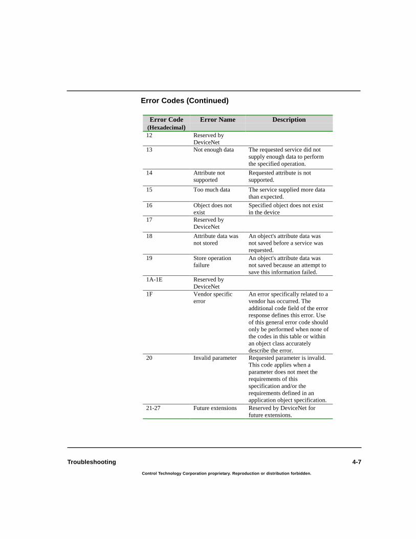
4-7
Control Technology Corporation proprietary. Reproduction or distribution forbidden.
Troubleshooting
Error Codes (Continued)
Error Code
(Hexadecimal)
Error Name Description
12 Reserved byDeviceNet
13 Not enough data The requested service did notsupply enough data to performthe specified operation.
14 Attribute notsupported
Requested attribute is notsupported.
15 Too much data The service supplied more datathan expected.
16 Object does notexist
Specified object does not existin the device
17 Reserved byDeviceNet
18 Attribute data wasnot stored
An object's attribute data wasnot saved before a service wasrequested.
19 Store operationfailure
An object's attribute data wasnot saved because an attempt tosave this information failed.
1A-1E Reserved byDeviceNet
1F Vendor specificerror
An error specifically related to avendor has occurred. Theadditional code field of the errorresponse defines this error. Useof this general error code shouldonly be performed when none ofthe codes in this table or withinan object class accuratelydescribe the error.
20 Invalid parameter Requested parameter is invalid.This code applies when aparameter does not meet therequirements of thisspecification and/or therequirements defined in anapplication object specification.
21-27 Future extensions Reserved by DeviceNet forfuture extensions.

4-8
Control Technology Corporation proprietary. Reproduction or distribution forbidden.
2716D DeviceNet Module Installation Guide
Error Codes for Explicit Messaging
Error Codes (Continued)
Error Code
(Hexadecimal)
Error Name Description
28 Invalid member ID Requested member ID does notexist in the specifiedclass/instance/attribute.
29 Member cannot beset
Request to modify a member isinvalid because the membercannot be modified.
2A-CF Future extensions Reserved by DeviceNet forfuture extensions.
D0-FF Reserved for objectclass
This range of error codes is usedto indicate object class andservice errors. Using this rangeshould only be performed whennone of the error codes in thistable accurately reflect the error.An additional field code isavailable that further describesany general error code.

Glossary
Glossary
Glossary-2
Control Technology Corporation proprietary. Reproduction or distribution forbidden.
2716D DeviceNet Module Installation Guide
GlossaryAssembly
A collection of data that consists of several objects within a device.
Asynchronous OperationAn operation that proceeds independently of any timing mechanism,such as a clock. For example, two modems communicating asynchro-nously rely upon each sending the other start and stop signals in order topace the exchange of information.
AttributesData that helps define an object by specifying a node address (MAC ID),object class identifier, instance number, and attribute number.
Baud RateThe speed at which a modem can transmit data. The baud rate is thenumber of events, or signal changes, that occur in one second—not thenumber of bits per second (bps) transmitted. In high-speed digitalcommunications, one event can actually encode more than one bit, andmodems are more accurately described in terms of bits per second thanbaud rate. For example, a so-called 9,600-baud modem actually operatesat 2,400 baud but transmits 9,600 bits per second by encoding 4 bits perevent (2,400 × 4 = 9,600) and thus is a 9,600-bps modem.
Bit StrobeA multicast master message that all supporting slaves use as a trigger toreturn input data. This message type is efficient and useful, especiallyfor sensor type devices that produce input data but do not consumeoutput data.
Bus-Off Interrupt (BOI)This action corresponds to an interrupt state that disables the DeviceNetinterface because of continuous streams of corrupted data. Data can becorrupted by large amounts of noise on the line, electronics/wiringproblems, and connecting or disconnecting network devices whilethey’re transmitting.
CANController Area Network. A broadcast-oriented communications proto-col with high reliability and fast response.
Change of State (COS)A feature on a slave device that sends data whenever a change hasoccurred or at a user-configurable heartbeat rate, whichever occurs first.

Glossary-3
Control Technology Corporation proprietary. Reproduction or distribution forbidden.
Glossary
ChannelA path or link through which information passes between two devices. Achannel can be either internal or external to a microcomputer.
ClassIn object-oriented programming, a generalized category that describes agroup of more specific items, called objects, that can exist within it. Aclass is a descriptive tool used in a program to define a set of attributesor a set of services (actions available to other parts of the program) thatcharacterize any member (object) of the class. Program classes arecomparable in concept to the categories that people use to organizeinformation about their world, such as animal, vegetable, and mineral,that define the types of entities they include and the ways those entitiesbehave. The definition of classes in object-oriented programming iscomparable to the definition of types in languages such as C and Pascal.
ConnectionA logical communications link between two devices on a DeviceNetnetwork. Connection types are defined by the types of messages that aretransmitted across the link and are either explicit or I/O. The number andtypes of connections you can establish depends on the design andprogramming of the DeviceNet device.
CyclicA feature that only sends data at a user-configurable heartbeat rate. Boththe master and slave produce data independently based on the value ofthe heartbeat rate.
Data MappingDefines how data is moved between the DeviceNet network and dataelements that are accessed by controller logic. Once data is mapped, thecontroller can access this data as if it is standard controller I/O.
DebounceSituation where a set of contacts closes or opens and bounces betweenstates before settling down to one value.
DeviceNetA low-cost, open network standard that connects industrial devices (suchas limit switches, sensors, etc.) to a network and eliminates expensivehardwiring. This direct connectivity provides improved communicationbetween devices as well as important device-level diagnostics not easilyaccessible or available through hardwired I/O interfaces.

Glossary-4
Control Technology Corporation proprietary. Reproduction or distribution forbidden.
2716D DeviceNet Module Installation Guide
Device ProfileA collection of standard and application-specific objects that define adevice as viewed from the network. Generally, this data includes adefinition of the device’s object model, its I/O format, and anyconfigurable parameters.
Device TypeIndicates the ODVA defined device profile that a device complies with.A vendor may include additional objects and/or attributes beyond thespecified minimums.
DroplineA connection from a trunkline to an individual controller or otherdevice.
Dynamic-Linked Library (DLL)A feature of the Microsoft Windows family of operating systems thatallows executable routines to be stored separately as files with DLLextensions and to be loaded only when needed by a program. A dy-namic-link library has several advantages. First, it does not consume anymemory until it is used. Second, because a dynamic-link library is aseparate file, a programmer can make corrections or improvements toonly that module without affecting the operation of the calling programor any other dynamic-link library. Finally, a programmer can use thesame dynamic-link library with other programs.
Electronic Data Sheet (EDS File)A file format that allows a vendor to release product-specific informa-tion to other vendors. For example, part of the EDS file for the 2716Dcontains the following type of information:
$ CTC 2716 DeviceNet Interface Electronic Data Sheet
[File]
DescText = "CTC2716D DeviceNet adapter";CreateDate = 06-26-98;CreateTime = 09:56:14;ModDate = 06-26-98;ModTime = 09:56:14;Revision = 1.1;
[Device]
VendCode = 254; $ Vendor CodeProdType = 0; $ Product TypeProdCode = 2716; $ Product Code
Glossary

Glossary-5
Control Technology Corporation proprietary. Reproduction or distribution forbidden.
Glossary
MajRev = 1; $ Major RevMinRev = 1; $ Minor RevVendName = "Control Technology Corporation";ProdTypeStr = "Generic";ProdName = "CTC 2716 DeviceNet";Catalog = "";
Explicit MessagesMessages directed at specific objects within a device that can determinethe current value of the object’s attributes or change the value of theseattributes. These messages are typically used for device configurationand diagnostics and are more generic and flexible than I/O messages.
Heartbeat RateAn adjustable, background rate used with change-of-state/cyclic mes-sages to detect that a producer is still in an active state on a network.Data is sent when it changes or when the heartbeat timer expires.
Human-Machine Interface (HMI)The set of commands, displays, controls, and hardware devices enablingthe human user and the computer system to exchange information. WithDeviceNet, HMIs monitor data in multiple slave devices and use thisinformation to determine what you see on a display.
I/O MessagesMessages that carry operational data based on the module’s configura-tion which are limited to specific sources and destinations within adevice. These messages are used for transferring control information,have less protocol overhead, and are more efficient than Explicit mes-sages.
IP AddressShort for Internet Protocol address. A 32-bit (4-byte) binary number thatuniquely identifies a host (computer) connected to the Internet to otherInternet hosts, for the purposes of communication through the transfer ofpackets. An IP address is expressed in “dotted quad” format, consistingof the decimal values of its four bytes, separated with periods; forexample, 127.0.0.1. The first one, two, or three bytes of the IP address,assigned by InterNIC Registration Services, identify the network thehost is connected to; the remaining bits identify the host itself. The 32bits of all 4 bytes together can signify almost 232, or roughly 4 billion,hosts (a few small ranges within that set of numbers are not used).

Glossary-6
Control Technology Corporation proprietary. Reproduction or distribution forbidden.
2716D DeviceNet Module Installation Guide
Inhibit TimeAmount of time that a device must maintain a COS condition.
Input BufferA portion of computer memory set aside for temporary storage ofinformation arriving for processing.
Input DataData that is produced by a DeviceNet device, collected by a scanner, andmade available to a controller.
InstanceAn object, in object-oriented programming, in relation to the class towhich it belongs. For example, an object myList that belongs to a classList is an instance of the class List. An instance might be used to definedifferent categories of the same class in situations where the same set offunctions is required but for different reasons or in different ways. Everyinstance shares a common data structure for the characteristics but hasits own set of this data and the individual values in the data structure areoften different between the instances. Each instance can then havedifferent operating characteristics.
InteroperabilityRefers to components of computer systems that are able to function indifferent environments. For example, Microsoft’s NT operating systemis interoperable on Intel, DEC Alpha, and other CPUs. Another exampleis the SCSI standard for disk drives and other peripheral devices thatallows them to interoperate with different operating systems. Withsoftware, interoperability occurs when programs are able to share dataand resources.
LayerThe protocol or protocols operating at a particular level within a proto-col suite, such as IP within the TCP/IP suite. Each layer is responsiblefor providing specific services or functions for computers exchanginginformation over a communications network (such as the layers outlinedin the ISO/OSI model) and information is passed from one layer to thenext. Although different suites have varying numbers of levels, generallythe highest layer deals with software interactions at the application level,and the lowest governs hardware-level connections between differentmachines.
LinkSee Connection.
Glossary

Glossary-7
Control Technology Corporation proprietary. Reproduction or distribution forbidden.
Glossary
Master/SlaveA network protocol defining the communications link between thecontrolling device (master) and the device (slave) responding to itscommands.
Media Access Control (MAC) IDA unique node address (0-63) on a network.
NodeA device that has a single address on the network and is capable ofcommunicating with other network devices.
ObjectAn abstract representation of a particular component within a product.
Open DeviceNet Vendor Association (ODVA)ODVA is an independent supplier organization which manages theDeviceNet Specification and supports the worldwide growth ofDeviceNet. ODVA works with vendors and provides assistance throughdeveloper tools, developer training, compliance testing and marketingactivities. ODVA publishes the DeviceNet product catalog and supportsvendor Special Interest Groups in developing Device Profiles forspecific classes of products.
Open StandardA publicly available set of specifications describing the characteristicsof a hardware device or software program. Open standards are publishedto encourage interoperability and thereby help popularize new technolo-gies.
Output DataData produced by the controller that is written to the module’s memoryand sent out to DeviceNet devices.
PacketA unit of information transmitted as a whole from one device to anotheron a network. In packet-switching networks, a transmission unit of fixedmaximum size that consists of binary digits representing both data and aheader containing an identification number, source and destinationaddresses, and sometimes error-control data.

Glossary-8
Control Technology Corporation proprietary. Reproduction or distribution forbidden.
2716D DeviceNet Module Installation Guide
ParameterIn programming, a value that is given to a variable, either at the begin-ning of an operation or before an expression is evaluated by a program.Until the operation is completed, a parameter is effectively treated as aconstant value by the program. A parameter can be text, a number, or anargument name assigned to a value that is passed from one routine toanother. Parameters are used as a means of customizing program opera-tion.
PollA message type that is initiated by the master device. It contains outputdata for a slave device which returns input data in a poll response.
Producer/ConsumerSetup where a client device (typically a master) produces requests andconsumes responses from a server device (typically a slave) that con-sumes requests and produces responses.
Production Inhibit TimeA COS configuration setting that is the minimum time between mes-sages. This setting helps prevent excessive bus traffic.
Scan TimeThe rate at which individual devices are polled. This interval is theelapsed time between the start of one scan and the start of the next scan.
ScannerA device (such as the 2716D) which is capable of functioning as amaster. This includes such functions as the pre-defined master/slaveconnection set and explicit peer-to-peer messages (UCMM). The scan-ner continuously scans a DeviceNet network to receive input data frommultiple slaves and makes this data available to a controller.
Service CodeThe service code is a standard code for all devices that is used to buildmessages. Codes such as Get_Attribute_Single, Set_Attribute_Single,Reset are the most commonly used codes.
Glossary

Glossary-9
Control Technology Corporation proprietary. Reproduction or distribution forbidden.
Glossary
ServicesRequests you can make on a network.
Shared MemoryMemory accessed by more than one program in a multitasking environ-ment. Also, a portion of memory used by parallel-processor computersystems to exchange information. In CTC controllers, shared memory isalso referred to as bi-port RAM.
SupervisorsMonitor specific data in slave devices and are also capable of receivingspecific data during troubleshooting.
TrunklineThe backbone of a network. It is the longest continuous wiring pathfrom one end of a network to another. In general, the trunkline has thelargest cable type and runs from one terminator.
UCMMUnconnected Message Manager. Provides for the dynamic establishmentof explicit messaging connections.

Bibliography
Bibliography

Bibliography-2 2716D DeviceNet Module Installation Guide
Control Technology Corporation proprietary. Reproduction or distribution forbidden.
Bibliography
Freedman, Alan. (1996). The Computer Desktop Encyclopedia. Amacom.
Hansen, Brad. (1999). The Dictionary of Computing and Digital Media, Terms and Acronyms.ABF Content.
Microsoft Corporation. (1998). Microsoft Press Computer Dictionary, 3rd Edition. MicrosoftPress.

Index
Index

Index-2 2716D DeviceNet Module Installation Guide
Control Technology Corporation proprietary, Reproduction or distribution forbidden.
IndexSymbols2716D
DIP switches, 1-8faceplate, 1-4hardware/firmware revision levels, 1-6installing, 1-10modes of operation, 1-2specifications, 1-5
AAnalog input status
register 13468, 3-6Analog output status
register 13469, 3-6
BBaud rate
how to set, 1-8Bit-strobe messages, 2-11Board handling precautions, 1-7BOI, 2-7
CCAN
description, 2-2Class ID
explicit messageregister 13595, 3-9
Configuration switchregister 13482, 3-6
Configuring the moduleas a master, 1-14as a slave, 1-19hardware, 1-8software, 2-7
Connection types, 2-3COS/Cyclic messages, 2-11–2-12
DData index for registers 13597-13599
register 13593, 3-8Data mapping, 2-4Data registers
explicit messages/general purposeregisters 13500-13589, 3-8
Device inaccessibilitytroubleshooting, 4-5
DeviceNetbenefits, 1-2connection types, 2-3connector
pinout diagram, 1-4data mapping, 2-4features, 2-2objects, 2-5scanning characteristics, 2-3special registers
13250-13399, 3-213400-13463, 3-213464-13465, 3-513466-13469, 3-613480-13482, 3-613499, 3-713500-13589, 3-813590-13593, 3-813594-13598, 3-913599, 3-10using, 3-10
theory of operation, 2-3Digital input status
register 13466, 3-6Digital output status
register 13467, 3-6DIP switches
setting, 1-8
EEDS file
description, 1-14Error codes
troubleshooting, 4-6ESD handling guidelines, 1-7Explicit messages, 2-12
FFragmentation, 2-13–2-15
HHardware configuration, 1-8Hardware/Firmware Revision Levels, 1-6

Index Index-3
Control Technology Corporation proprietary, Reproduction or distribution forbidden.
II/O assembly
definition, 1-15I/O connections
limitations, 1-22I/O data registers
registers 13250-13399, 3-2I/O messages, 2-10–2-11Individual module status
registers 13400-13463, 3-2Installing the module, 1-10Instance value
explicit messageregister 13596, 3-9
LLED
status indicatorsfaceplate, 1-4
troubleshootingnetwork status, 4-3
troubleshooting tablesdevice status, 4-4
MMACID
how to set, 1-9Master devices
configuring, 1-14man-machine interface, 2-6scanners, 2-6supervisors, 2-6
Master mode, 1-2disabling, 1-18
Message number and register statusregister 13591, 3-8
Messagingacknowledgments, 2-14explicit, 2-12fragmentation, 2-13–2-15I/O, 2-10–2-11
bit strobe, 2-11COS/cyclic, 2-11poll, 2-11
overhead, 2-15–2-17types, 2-5
MMIdescription, 2-6
Module ID for explicit messagingregister 13590, 3-8
Monitor mode, 1-2
NNetwork
device configuration, 1-13DeviceNet connections, 1-12general setup, 1-13
OObjects, 2-5Overhead
messaging, 2-15–2-17
PPinout diagram
DeviceNet connector, 1-4Poll messages, 2-11Port addressing, 1-24
RRegister count
bit strobe slave responseregister 13492, 3-7
poll slave inputregister 13494, 3-7
poll/COS slave responseregister 13496, 3-7
Register objectsdescription, 2-5input data, number of registers, 2-8output data, number of registers, 2-7
Register request timing parameter, 2-9Register set objects
description, 2-5input data start register, poll command, 2-8output data start register, 2-7response data, number of registers, bit strobe, 2-9response data start register, bit strobe, 2-9
Requested and actual explicit message formatregister 13592, 3-8

Index-4 2716D DeviceNet Module Installation Guide
Control Technology Corporation proprietary, Reproduction or distribution forbidden.
Index
Retry timequickstep example, 3-3registers 13400-13463, 3-2
RS-232communications
computer-controller connections, 1-25configuring ports, 1-24
connectorsfaceplate, 1-4
RS-485communications
changing a jumper, 1-3configuring ports, 1-24connections, 1-26connector
faceplate, 1-4
SScan
list, 2-4time, 2-4
Scannerbaud rate
register 13481, 3-6description, 2-6MACID
register 13480, 3-6module status
register 13465, 3-5status
register 13464, 3-5Selected data
signed byteregister 13597, 3-10
signed long integerregister 13599, 3-10
signed wordregister 13598, 3-10
Sequence number, 2-14Serial communications
troubleshooting, 4-5Service code
description, 2-14explicit message
register 13594, 3-9Slave devices
configuring, 1-19Slave mode, 1-2Software configuration, 2-7Specifications, 1-5Start register
poll slave inputregister 13493, 3-7
poll/COS slave responseregister 13495, 3-7
Supervisorsdescription, 2-6
TTheory of operation, 2-3Transaction ID (XID), 2-13Troubleshooting
error codes, 4-6general problems, 4-5inaccessible devices, 4-5LED troubleshooting tables, 4-3serial communications, 4-5typical causes of problems, 4-2
UUpdate cycle for slave mode
register 13499, 3-7