Embed Size (px)
Citation preview

INJECTOR
®
-
CHEMFEEDI
I
BLUE-WHITE
NDUSTRES
ne
h
HuntingtoB
ac
CA 92649
www
.Blue White.com
-
MODEL C-1700NPositive Displacement Injector Pump
Operating Manual
5300 Business DriveHuntington Beach, CA 92649
USAPhone: 714-893-8529 FAX: 714-894-9492
E mail: [email protected] or [email protected]
Blue-WhiteIndustries, Ltd.
R

C-1700N Page 2
TABLE OF CONTENTS
SECTION HEADING PAGE
1 Introduction 2
2 Specifications 2
3 C-1700N Features 3
4 How to install the C-1700N 3
4.1 Mounting location 3
4.2 Electrical connections 5
4.3 How to install the tubing and fittings 6
5 How to operate the C-1700N 8
5.1 Adjusting the Pump Output - Standard Models 8
5.2 Adjusting the Pump Output - Fixed cycle timer Models 9
5.2 Measuring the pump’s output - volumetric test 9
6 How to maintain the C-1700N 9
6.1 Routine inspection and cleaning 9
6.2 How to clean the C-1700N 9
1.0 Introduction
Thank you for purchasing the C-1700N positive displacement metering pump. The C-1700N is designed to inject chemicals into piping systems. The pump has been tested by NSF International for use with 12 ½% Sodium Hypochlorite. All models are equipped with two top mounted mechanical flow rate adjust-ment knobs. Optional on/off cycling timers are available.
2.0 Specifications
Maximum Working Pressure 125 psig / 8.6 bar*o o
Maximum Fluid Temperature 130 F / 54 Co
Output Accuracy +/- 10% of maximum (water @ 70 F, 0 psig, and 5’ suction lift)o o
Ambient Temperature Range 14 to 110 F / -10 to 43 C
Enclosure NEMA 3R (acceptable for outdoor use)
Duty Cycle Continuous
Maximum Viscosity 1,000 Centipoise
Maximum Suction Lift up to 10 ft. water
Power Requirements 115V60Hz 45 Watts
220V50Hz 45 Watts
230V60Hz 45 Watts
24V60Hz 45 Watts
Dimensions 9-1/16” high x 4-1/2” wide x 7-5/32” deep
Weight 7.5 lb.

C-1700N
3.0 C-1700N Features� Double-ball ceramic check valves.
� PVDF (Kynar) valve assemblies.
� Viton o-rings.
� High outlet pressure capability of 125 PSIG.*
� Easy access, top mounted mechanical feed rate adjustment.
� Ball bearing supported motor drive shaft.
� Permanently lubricated ball bearing motor.
� 20:1 adjustment turn down ratio.
� Acceptable for outdoor use. (NEMA 3R; IP23)
� Corrosion resistant Valox housing.
� Easy servicing.
� Includes suction tube foot valve & strainer, suction tube weight, suction tubing, discharge tubing and injection fitting with internal back-flow check valve and mounting hardware.
* Most models.
Page 3
4.0 How To Install the C-1700N
Note: All diagrams are strictly for guideline purposes only. Always consult an expert before installing the C-1700N into specialized systems.The C-1700N should be serviced by qualified persons only.
4.1 Mounting Location
Choose an area located near the chemical supply tank, chemical injection point and electrical supply.Although the pump is designed to withstand outdoor conditions, a cool, dry, well ventilated location is recommended. Install the pump where it can be easily serviced.
� Mount the pump to a secure surface or wall using the enclosed hardware. Wall mount to a solid surface only. Mounting to drywall with anchors is not recommended.
� Keep the outlet (discharge) tubing as short as possible. Longer tubing increases the back pressure at the pump tube.
� Do not mount the pump directly over your chemical container. Chemical fumes may damage the unit.Mount the pump off to the side or at a lower level than the chemical container.
� Mounting the pump lower than the chemical container will gravity feed the chemical into the pump. This“flooded suction” installation can reduce the time required to prime the pump. Install a shut-off valve, pinch clamp or other means to halt the gravity feed to the pump during servicing.
� Your solution tank should be sturdy. Keep the tank covered to reduce fumes.
� Be sure your installation does not constitute a cross connection with the drinking water supply. Check your local plumbing codes.

C-1700N
FIG. 4.2 TYPICAL INSTALLATION
Page 4
DischargeTube
Pumping unit
Chemical# 1
¼ ½ P I j t r" & " N T n ec o
C-1700N
4-1/2”
9-1/16”
7-5/32”
FIG. 4.0 DIMENSIONAL DRAWING FIG. 4.1 INJECTOR WALL MOUNTING
#10 Self-Tap(2 X)
2.30”Slide in
ClampWall Mount
Chemical# 2
¼" ½" P I j t r& N T n ec o
DischargeTube
SuctionTube
SuctionTube

C-1700NPage 5
4.2 Electrical Connections
4.2.1 Input Power Connections
Be certain to connect the pump to the proper supply voltage. Using the incorrect voltage will damage the pump and may result in injury. The voltage requirement is printed on the pump serial label.
Note: When in doubt regarding your electrical installation, contact a licensed electrician.
The C-1700N is supplied with either a ground wire conductor and a grounding type attachment plug (power cord) or a junction box for field wiring.
POWER CORD MODELS -To reduce the risk of electric shock, be certain that the power cord is connected only to a properly grounded, grounding type receptacle.
JUNCTION BOX MODELS -To reduce the risk of electric shock, be certain that a grounding conduc-tor is connected to the green grounding conductor located in the junction box.
FIG. 4.4 WIRING DIAGRAM - STANDARD MODELS
ACMOTOR
INPUTVOLTAGE
115V 60Hz
HOTLEADWIRE
NEUTRALLEADWIRE
GROUNDLEADWIRE
230V 60Hz
BLUE or YELLOW
BLUE
BROWN
RED
GREEN
GREEN
GREEN
MOTOR LEADWIRES
Neutral
Hot
Ground (green)Earth Ground (green)
Common
Hot
ACInputPower
220V 50Hz
BLACK or YELLOW
BLACK or YELLOW
* Yellow leadwire : thermally protected motor Black or Blue leadwire: standard impedance protected motor
*
*
*
24V 60Hz WHITE GREENBLUE *

4.3 How To Install the Tubing and Fittings
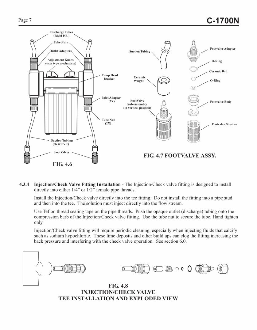
4.3.1 Inlet Tubing - Locate the inlet fitting of the pump head, see fig 4.6. Remove the tube nut. Push the clear PVC suction tubing onto the compression barb of the fitting. Use the tube nut to secure the tube. Hand tighten only.
4.3.2 Footvalve/Strainer -Trim the inlet end of the suction tubing so that the strainer will rest vertically approximately one inch from the bottom of the solution tank. This will prevent sediment from clogging the strainer. Slip the ceramic weight over the end of the suction tube. Press the footvalve/strainer into the end of the tube. Secure the ceramic weight to the strainer. Drop the strainer into the solution tank. Be sure the footvalve does not lay horizontally on the bottom of the solution tank.
4.3.3 Outlet Tubing - Locate the outlet fitting of the pump head, see fig 4.6. Remove the tube nut. Push the opaque outlet (discharge) tubing onto the compression barb of the fitting. Use the tube nut to secure the tube. Hand tighten only.
Trim the other end of the outlet tube leaving only enough slack to connect it to the Injection/Check valve Fitting (see below). Increasing the length of the outlet tube increases the back pressure at the pump head, particularly when pumping viscous fluids.
Keep the inlet and outlet tubes as short as possible.
C-1700N Page 6
FIG. 4.5 WIRING DIAGRAM - FIXED TIMERS
(factory Setting)
Cycle AdjustmentPotentiometer
T3
T2
T1 ACInputPower
Hot
Common
Ground (green)
TimerBoard
Hot
Neutral
AC/LOAD
AC
LOAD
JB2 JB3JB1
ACMotor
JB1, JB2, JB3 = Voltage Selector JumpersJumpers ConfigurationInstall JB2 & JB3, (JB1 left open) = 24 V AC inputInstall JB1 & JB3, (JB2 left open) = 115 V AC inputRemove all jumpers (JB1, JB2, & JB3 left open) = 220V, 230 V AC input
C-1700NPage 7
FootValveSub-Assembly
(in vertical position)
CeramicWeight
Suction TubingFootvalve Adapter
O-Ring
Ceramic Ball
O-Ring
Footvalve Body
Footvalve Strainer
FIG. 4.7 FOOTVALVE ASSY.
4.3.4 Injection/Check Valve Fitting Installation - The Injection/Check valve fitting is designed to install directly into either 1/4” or 1/2” female pipe threads.
Install the Injection/Check valve directly into the tee fitting. Do not install the fitting into a pipe stud and then into the tee. The solution must inject directly into the flow stream.
Use Teflon thread sealing tape on the pipe threads. Push the opaque outlet (discharge) tubing onto the compression barb of the Injection/Check valve fitting. Use the tube nut to secure the tube. Hand tighten only.
Injection/Check valve fitting will require periodic cleaning, especially when injecting fluids that calcify such as sodium hypochlorite. These lime deposits and other build ups can clog the fitting increasing the back pressure and interfering with the check valve operation. See section 6.0.
FIG. 4.8INJECTION/CHECK VALVE
TEE INSTALLATION AND EXPLODED VIEW
Discharge Tubes(Rigid P.E.)
Outlet Adapters
Tube Nuts
Inlet Adapter(2X)
Tube Nut(2X)
Suction Tubings(clear PVC)
FootValves
FIG. 4.6
Pump Headbracket
Adjustment Knobs(cam type mechanism)

5.0 How To Operate The C-1700N
5.1 Adjusting the Pump Output- Standard models (fig. 5.1) - The C-1700N flow rate(s) can be adjusted within a range of 5% -100% of maximum output (20:1 turndown ratio) by means of two mechanical, cam type mechanisms. The mechanism adjusts the pump’s stroke length to an infinite number of settingswithin the flow range. Because the pump’s output is reduced by increasing the pressure of the system being injected into, the amount of suction lift, and the viscosity of the fluid being injected, the pump must be over-sized to allow for these factors. Sizing the pump to allow adjustment within the midrange is preferred to maintain accuracy. Consult the factory for individual pump model output curve data.
To adjust the pump’s output:
1. With the pump running, loosen the set screw.
2. Turn the adjustment knob to the desired setting.
3. Re-tighten the set screw.
C-1700N Page 8
5.2 Adjusting the Pump Output - DELUXE Models (fig. 5.2)
In addition to the two cam type mechanism adjustments (section 5.1), the pump output of the C-1700N deluxe unit equipped with an optional electronic cycle timer board can also be fine tuned by adjustingthe timer adjustment knob. The total-time cycle is factory preset and is not user adjustable. The on-time cycle is adjustable from 5% to 100% of the total cycle time. Example: If the total-time cycle is 5 seconds and the on-time cycle is adjusted for 20 percent, the pump will run for 1 second and turn off for 4 seconds (5 second total cycle). This cycle is repeated until either the cycle time is changed or the input power is disconnected from the pump.
Note: When the input power is disconnected from the C-1700N, the unit will maintain the last adjusted settings. When power is restored to the pump, the C-1700N will begin to pump using the last time cycle setting.
FIG. 5.2
To adjust the On-Time :
Turn the timer adjustment knob located on the junction box cover.
Clockwise increases the time on.
FIG. 5.1
Adjustment Knobs(Cam Type Mechanism)
Cycle TimerAdjustment Knob
Junction Box
MAX
MIN
1 23
4
5
6
789
MAX
MIN
123
4
5
6
78 9ADJUST WHILE
RUNNING
LOOSEN SCREW
TURN KNOB
RE-TIGHTEN SCREW

C-1700NPage 9
5.3 Measuring the Pump’s Output - Volumetric Test.
This volumetric test will take into account individual installation factors such as line pressure, fluidviscosity, suction lift, etc. This test is the most accurate for measuring the injector’s output in an individ-ual installation.
1. Be sure the Injection Fittings and Footvalves/Strainers are clean and working properly.
2. With the injector installed under normal operating conditions, place the Footvalve/Strainer in a largegraduated cylinder.
3. Fill the graduated cylinder with the solution to be injected and run the injector until all air is removed from the suction line and the solution enters the discharge tubing.
4. Refill the graduated cylinder, if necessary, and with the Footvalves completely submerged in the solution, note the amount of solution in the graduated cylinder.
5. Run the injector for a measured amount of time and note the amount of fluid injected. A longer testing time will produce more accurate results.
6.0 How to Maintain the C-1700N
6.1 Routine Inspection and Maintenance
The C-1700N requires very little maintenance. However, the pump and all accessories should be checked regularly. This is especially important when pumping chemicals. Inspect all components for signs of leaking, swelling, cracking, discoloration or corrosion. Replace worn or damaged components immediately.
Cracking, crazing, discoloration and the like during the first week of operation are signs of severe chemical attack. If this occurs, immediately remove the chemical from the pump. Determine which parts are being attacked and replace them with parts that have been manufactured using more suitable materials. The manufacturer does not assume responsibility for damage to the pump that has been caused by chemical attack.
6.2 How to Clean the C-1700N
The C-1700N will require occasional cleaning, especially the Injection fittings, the Footvalves/Strainers,and the pump head valves. The frequency will depend on the type and severity of service..
� When changing the diaphragm, the pump head chamber and pump head cover should be wiped free of any dirt and debris.
� Periodically clean the injection/check valve assembly, especially when injecting fluids that calcify such as sodium hypochlorite. These lime deposits and other build ups can clog the fitting, increase the back pressure and interfere with the check valve operation. See section 4.3.4. Fig. 4.8.
� Periodically clean the suction strainers. Fig.4.7
� Periodically inspect the air vents located under the motor compartment and under the pump head. Cleanif necessary.

C-1700N
Replacement Parts Drawing
Page 10
45
42
44
43
46
47
48
49
50
48 51
52
53
54
12
17
18
20
21
22
23
26
27
29
37
36
38
39
41
40
2524
13
10
11
15
14
16
55
9
2
1
4
3
6
8
7
28
19
30
31
32
33
5
34
35

C-1700NPage 11
Item
Part
No
Des
crip
tion
Qty
Item
Part
No
Des
crip
tion
Qty
C-1
70
0N
PA
RT
SL
IST
190002-0
86
Scr
een,F
ootV
alve,
P.P.
2
290002-2
14
Body,
FootV
alve,
PV
DF
2
390003-1
26
O-r
ing
Sea
t,F
ootV
alve,
Vit
on
2
90003-1
29
O-r
ing
Sea
t,F
ootV
alve,
E.P
.2
490008-0
62
Bal
l,F
ootV
alve,
Cer
amic
2
590003-0
14
O-r
ing,F
ootV
alve,
Vit
on
2
90003-0
15
O-r
ing,F
ootV
alve,
E.P
.2
690002-2
15
Adap
ter,
FootV
alve,
PV
DF
2
771000-3
24
FootV
alve
S/A
,C
-340E
,E
P2
71000-3
25
FootV
alve
S/A
,C
-340V
,V
T2
890008-0
68
Cer
amic
wei
ght,
C-3
46
2
970000-6
38
Tube
Indic
ator
Gla
ss3/8
x5F
T2
76000-1
71
Tube
Suct
ion
1/4
x5F
T2
10
90002-0
77
Tube
Nut,
.37T
,P.
P.4
90002-0
47
Tube
Nut,
.25T
,P.
P.4
11
71000-2
04
Adap
ter
S/A
Bull
et.3
7T
Vit
on
4
71000-2
05
Adap
ter
S/A
Bull
et.3
7T
EP
4
71000-2
24
Adap
ter
S/A
Bull
et.3
7T
Sil
icon
4
71000-2
25
Adap
ter
S/A
Bull
et.2
5T
Vit
on
4
71000-2
26
Adap
ter
S/A
Bull
et.2
5T
EP
4
71000-2
27
Adap
ter
S/A
Bull
et.2
5T
Sil
icon
4
12
71000-1
95
Car
trid
ge
Bull
etV
alve
S/A
,D
ouble
-Bal
l2
13
70004-0
74
Cover
P/H
ead,H
DC
hem
-Fee
dlo
go
2
70004-0
71
Cover
P/H
ead,H
DN
oir
logo
2
70004-0
86
Cover
P/H
ead,H
DM
icro
logo
2
14
90011-1
41
Scr
ew10-3
2x
1.2
54
15
90002-1
46
P/H
ead
Noir
Mold
ed,P.
P.2
16
76000-1
68
Tubin
gD
/Char
ge,
3/8
x5F
T2
76000-1
69
Tubin
gD
/Char
ge,
1/4
x5F
T.
2
17
C-4
06
VT
-17N
Dia
phra
gm
S/A
2.0
17N
,V
iton/T
FE
2
C-4
06T
-17N
Dia
phra
gm
S/A
2.0
17N
,E
P/T
FE
2
R-1
06V
T-1
7N
Dia
phra
gm
S/A
1.6
17N
,V
ito
n/T
FE
2
R-1
06T
-17N
Dia
phra
gm
S/A
1.6
17N
,E
P/T
FE
2
18
90006-0
22
Ret
urn
Spri
ng
C-1
700N
4
19
76000-2
88
Sti
rr-u
p2
20
90002-0
01
Sli
de
Bea
ring
4
21
90001-1
32
Off
set
Cam
#1
.125”
2
90001-1
33
Off
set
Cam
#2
.055”
2
90001-1
34
Off
set
Cam
#3
.187”
2
90001-1
41
Off
set
Cam
#4
.100”
2
22
90002-0
17
Dia
lK
nob
2
23
90012-2
20
Lab
el,T
op
Cover
1
24
90011-1
68
Scr
ew#6
x.6
2P
Hoval
‘A’
4
25
76000-9
38
Top
Cover
1
26
90011-1
21
Thum
bS
crew
6-3
2x
1.1
25
2
27
90006-5
99
Gas
ket
,T
op
Cover
1
28
90004-0
05
Bea
ring,T
op
Cover
1
29
70000-1
31
Dri
ve
Cam
S/A
#1
.125”
1
70000-1
33
Dri
ve
Cam
S/A
#2
.055”
1
70000-1
32
Dri
ve
Cam
S/A
#3
.187”
1
70000-7
22
Dri
ve
Cam
S/A
#4
.100”
1
30
90011-0
14
Spac
er,R
oto
r1
31
90011-1
22
Scr
ew10-3
2x
.50
PH
LPA
N4
32
76000-9
37
Moto
rM
ount,
Lar
ge
Dia
phra
gm
1
33
90008-1
38
Plu
g.3
12
Hole
Bla
ck1
34
90002-1
06
Cla
mp
C-1
7N
Wal
lM
ount
1
35
90011-1
22
Scr
ew10-3
2x
.50
PH
LPA
N2
36
90006-5
97
Gas
ket
,M
oto
rM
ount
1
37
76000-6
30
Sli
de
Cla
mp
2
38
76000-9
39
Moto
rC
over
C-1
7N
115V
176000-9
40
Moto
rC
over
C-1
7N
220/2
30V
1
39
90003-5
13
Bum
per
Fee
t4
40
70000-5
89
Connec
tor
Liq
-Tit
ew
/nut
1
41
90010-1
10
Cord
18/3
SJT
W/A
115v
1
90010-1
28
Cord
18/3
SJT
W/A
Euro
pea
nB
LK
1
90010-1
33
Cord
18/3
SJT
W/A
230v
BL
K1
42
71000-1
33
Cover
,Ju
nct
ion
Box
wit
hG
asket
and
Lab
el1
43
90007-5
15
Bush
ing,Ju
nct
ion
Box
Connec
tor,
Alu
m.
1
44
76000-5
22
Junct
ion
Box,V
alox
1
45
90011-1
29
Scr
ew,C
over
,6-3
2X
.25
Phil
Pan
SS
Bla
ck2
46
90006-5
98
Fan
,1.8
0”
Dia
met
er,A
lum
.1
47
90011-0
22
Scr
ew,M
oto
r,8-3
2X
2.5
”P
hil
lips
Ste
el2
48
70000-0
28
Bea
ring
Bra
cket
Wit
hB
eari
ng
2
49
70000-0
27
Roto
rA
ssem
bly
Wit
hS
haf
tA
nd
Spac
ers
1
50
70000-0
18
Sta
tor
S/A
,115V
60H
zS
tandar
dB
lue-
Bla
ck1
70000-0
19
Sta
tor
S/A
,115V
60H
zT
her
mal
Blu
e-Y
ello
w1
71000-0
19
Sta
tor
S/A
,220V
50H
zS
tandar
dB
row
n-B
lack
1
71000-0
20
Sta
tor
S/A
,220V
50H
zT
her
mal
Bro
wn-Y
ello
w1
70000-0
20
Sta
tor
S/A
,230V
60H
zS
tandar
dR
ed-B
lack
1
70000-0
21
Sta
tor
S/A
,230V
60H
zT
her
mal
Red
-Yel
low
1
70000-0
72
Sta
tor
S/A
,24V
60H
zS
tandar
dB
lue-
Whit
e1
51
90011-0
24
Gro
und
Scr
ew8-3
2x
.25
Hex
SL
ST
1
52
90010-1
27
Lea
dW
ire,
gro
und,G
reen
1
53
90011-0
78
Was
her
,G
round
Scr
ew,#8
Intr
l/S
tar
1
54
71000-2
68
Gea
rbox,14
RP
M1
71000-2
69
Gea
rbox,30
RP
M1
71000-2
70
Gea
rbox,45
RP
M1
71000-2
71
Gea
rbox,60
RP
M1
71000-2
72
Gea
rbox,125
RP
M1
55
70000-4
39
Inje
ctio
nV
alve
S/A
37T
VIT
1/2
PS
I1
(N/s
)90010-1
53
Cycl
eT
imer
5S
ec.24V
-115V
-230V
50/6
0H
z1
(N/s
)90010-1
51
Cycl
eT
imer
1M
in.24V
-115V
-230V
50/6
0H
z1
(N/s
)90010-1
52
Cycl
eT
imer
10
Min
.24V
-115V
-230V
50/6
0H
z1

LIMITED WARRANTYYour new pump is a quality product and is warranted to be free of defects as set down in this policy. All parts, including rubberized goods, and labor are covered under warranty for 90 days from the date of purchase. Used peristaltic pump tube assemblies are not warranted. Parts, excluding rubberized goods, are covered under warranty for 12 months from the date of purchase.Warranty coverage does not include damage to the pump that results from misuse, carelessness, abuse or alteration. Only the repair or the replacement of the pump is covered. Blue-White Industries does not assume responsibility for any other loss or damage.Warranty status is determined by the pump’s serial label and the sales invoice or receipt. The serial label must be on the pump and the pump must be accompanied by the sales invoice or receipt to obtain warranty coverage. The warranty status of the pump will be verified by Blue-White or a factory authorized service center.
Please be advised; injection and metering devices are not intended as a means of treating water to render it suitable for human consumption. Whenused as hypochlorinators, they are meant to destroy bacteria and algae contamination, before it’s removal by filtration. Acid and soda injectors are used for PH control (balance). Blue-White injectors are factory tested with water only for pressure and performance. Installers and operators of these devices must be well informed and aware of the precautions to be taken when injecting various chemicals -especially those considered hazardous or dangerous.Should it become necessary to return an injector for repair or service, you must attach information regarding the chemical used as some residue may be present within the unit which could be a hazard to service personnel.Blue-White Industries will not be liable for any damage that may result by the use of chemicals with their injectors and it’s components. Thank you.
PROCEDURE FOR IN WARRANTY REPAIRCarefully pack the pump to be repaired, include the foot strainer and injection/check valve fitting. Enclose a brief description of the problem as well as the original invoice or sales receipt showing the date of purchase. The receipt will be returned with the unit. Prepay all shipping costs. COD shipments will not be accepted. Warranty service must be performed by the factory or an authorized service center. Damage caused by improper packaging is the responsibility of the sender.
AUTHORIZED SERVICE CENTERS
ARKANSAS Rice Pump & Motor Repair NEW YORKBT Environmental, Inc 5788 N. Powerline Road Sherwood Specialties, Inc.Bill Thomason Ft. Lauderdale FL 33309 412 Smith Street225 Castleberry Street 305-776-6049 Rochester, NY 14608Hot Springs, AR 71902 716-546-1211
American Pump501-624-3837
7580-A W. Tennessee St.NORTH CAROLINA
CALIFORNIA (NORTHERN) Tallahassee, FL 32304Southern Industrial Sales
904-575-9618Howard E. Hutching company 1903 Herring Avenue(Repair Center) Del Ray Electric Wilson, NC 278937190 Penryn Plaza 11 N.E. 2nd Avenue 919-237-2500Penryn, CA 95663 Del Ray Beach, FL 33444
407-278-3976 PENNSYLVANIAPool-Tech, Inc.
Armor Electric, Inc.3471 Mt. Diablo Blvd.
Jerry Lee Chemical Co. 1425 Selinger AvenueLafayette, CA 94549
3407 W. Old Fairfield Drive Erie, PA 16505415-284-1400
Pensacola, FL 32505 814-838-2034Swimco Electric Co. 904-432-9929753 Camden Avenue SOUTH DAKOTACampbell, CA 95008 Picard Chemical Son-Aqua Distributing408-378-2607 1670 S. Congress Avenue Jim Robinson
W. Palm Beach, FL 33406 2447 W. Main StreetCALIFORNIA (SOUTHERN)
407-965-3434 Rapid City, SD 57702Blue-White Industries 605-343-7716(Repair Center) V.J. Mini & Son, Inc.5422 Business Drive 1581 N. Dixie Highway TENNESSEEHuntington Bch. CA 92649 Pompano Beach, FL 33060 Rock City Machine714-893-8529 305-946-0920 307 3rd Avenue South
Nashville, TN 37201COLORADO
ILLINOIS 615-244-1371Denver Winpump
Mullarkey Associates655 Depew StreetTEXAS(Repair Center)Lakewood, CO 80214-2494Alamo Water Refiners
303-233-1121 12346 S. Keeler Ave.13700 Hwy. 90 West
Alsip, IL 60658CONNECTICUT San Antonio, TX 78245
708-597-5558Cronin-Cook & Associates 512-677-840024 West Road
MARYLANDVernon, CT 06066 EGCO Industries
Century Pool Service, Inc203-875-0544 8505 Director Row
5020 Nicholson Court, #201Dallas, TX 75247
FLORIDA Kensington, MD 20895214-631-6885
AAA Electric Motor Services 301-231-89991131 N.E. 45th Street
Miracle Water Conditioning Co.Ft. Lauderdale, FL 33334 NEVADA
Robert Shelton305-772-7501 Swim-In Enterprises, Inc.
1011 Oakmead Drive1314 S. Main Street
All American Pool & Patio Arlington, TX 76011Las Vegas, NV 89104
2021 Curry Ford Road 817-640-6188702-384-4223
Orlando, FL 32806407-898-8722
# 81000-265 07/28/2003