Embed Size (px)
Citation preview

OPERATION MANUAL 32” and 36” Heavy Duty Rigging Sheaves
Manufactured by Wireline Technologies, Inc.
Serial Number _________

1
Introduction This manual explains the use and care of 36” rigging sheaves manufactured by Wireline Technologies, Inc. Please read and become familiar with all of the information in this manual before using this equipment.
Features ⇒ 18” bend radius for less wireline bend damage. ⇒ High load capacity of 40,000 lbs. ⇒ Sealed bearings for long maintenance-free operation. ⇒ Corrosion Resistant Materials ⇒ Non-spoked wheel for safer operation.
• Read entire manual before operating this equipment. • If proper procedures are not followed, loads may disengage. • A falling load can cause serious injury or death. • Never use this product for hoisting personnel. • Always anchor or hang the sheave via the clevis, never by way of any ancillary equipment. • Never apply more force than the Safe Working Load (SWL) listed on the affixed tag. • The listed Safe Working Load is for the sheave assembly; the safe line tension will be less. • Attachment to other equipment with lower SWL will reduce the allowable load. • Always use a hand guard when the sheave is used around personnel. • Always make sure the sheaves are properly maintained and properly rigged.
! WA
RN
ING
S !

2
Safe Working Load The rated safe working load (SWL) for a WTI 32” or 36” sheave is 40,000 lbs. (18,140 kg.). The allowable line pull will depend upon the angle the line is deflected. If the sheave is used as a top sheave, it deflects the line 180°, see figure 1. If the sheave is used as a bottom sheave, it deflects the line 90°, see figure 2. Never exceed the SWL, unless special precautions are taken in accordance with your company’s policy. These precautions should include, but are not limited to, clearing the rig floor of all personnel. If the SWL is exceeded, the sheave should be re-certified before it can safely be placed back in service.
Top Sheave Max. Line Tension 20,000 lbs (9,070 kg) Bottom Sheave Max. Line Tension 28,280 lbs (12,820 kg)
Safe Line Tension for 90-Degree Deflection Figure 2
Safe Line Tension for 180-Degree Deflection Figure 1
3
Clevis Options Five clevis swivel assembly options for suspending/anchoring the sheave are available: These options are shown in figures 3 – 6 below. The Clevis-Eye has an opening about 4” X 6” for a chain or shackle. The opening width of the Clevis-Atlas is 1 3/4” with a hole for a 1” pin. The opening width of the Clevis-Halliburton is 1.3” with a hole for a 1” pin. The opening width of the Clevis-Schlumberger is 2” with a hole for a 2” pin.
Clevis–Eye Part # RS-36-1352
Figure 3
Clevis-Atlas Part # RS-36-1252
Figure 4
Clevis-Halliburton Part # RS-36-1552
Figure 5
Clevis–Schlumberger Part # RS-36-1652
Figure 6
4
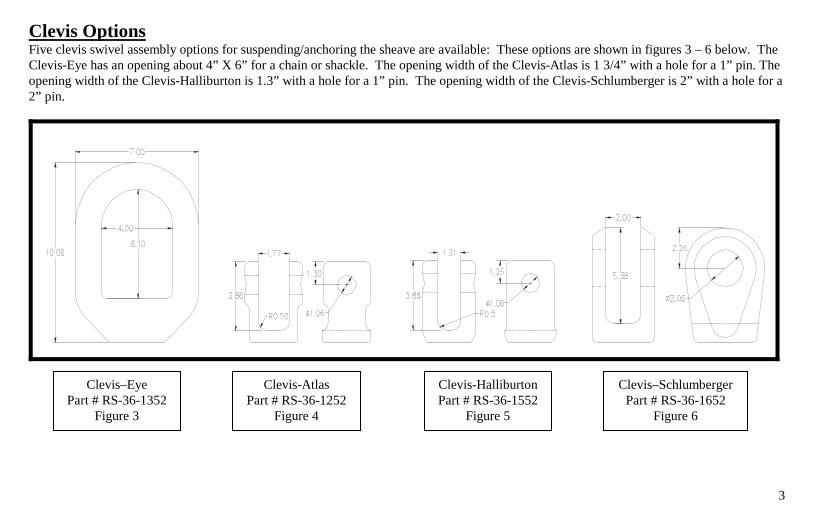
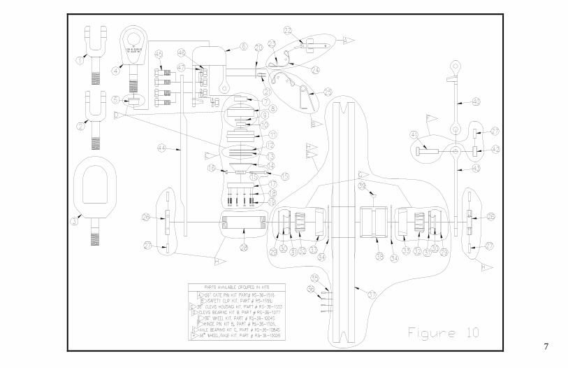
Loading Th1. 2. 3. 4. 5. 6. Install the gate pin through the holes. 7. Replace the safety clip making sure the hooked end is clipped over th
e numbers listed refer to figure 10 and table 1 on pages 7 and 8. Remove safety clip (8). Remove the gate pin (7). Open the loading gate (4). Load line into groove of wheel (32). See figure 7. Close the loading gate, aligning its holes with the holes in the frame (3).
e straight end. See figure 8.
Properly Loaded Line Figure 7
Properly Closed Gate Figure 8
5
Daily Inspection Checklist Verify the following. If any discrepancies are noted, remove the sheave from service until repairs are completed. The numbers listed refer to figure 10 and table 1 on pages 7 and 8.
All structural components (1,3,4,6,7,25,32, 44) are not bent, cracked, or otherwise damaged. Loading gate (4) hinges freely through the fingers in the frame (3). Gate pin (7) can be easily inserted through the holes in the frame (3) and is securely attached with a lanyard (9). Manufacturing tag (35) is in place and readable. Inspection tag (37) is in place and stamped with an inspection date no greater than one year old. Spiral pins (24) are in place and securely retain the axle nuts (23,34) on the axle (25). Wheel (32) rotates freely and smoothly, check for any grinding or sticking, indicating damaged bearings. Gate pin (7) and safety clip (8) are undamaged, lock positively, and are securely attached with lanyards (9). Clevis (1) pivots freely and does not have excessive slop (more than 1/4” axially or 1/8” radially). All 10 cap screws (22) and lock-washers (21) are tightly in place. Bushing (2) is in place and undamaged. All four nuts (46) are secure.
Preventative Maintenance WTI suggests the following service. Numbers listed refer to figure 10 and table 1 on pages 7 and 8.
The wheel bearings (11) are sealed and only need annual re-packing. Use lithium based No.2 EPHT grease, such as Conoco’s Tacna® RX. This service can be performed at the same time as the annual recertification. See page 6.
Monthly, squirt some light machine oil on the hinge pin (5) (between the fingers of the gate frame (6) and the loading gate (4), and onto the gate pin (7).
6
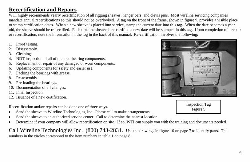
Recertification and Repairs WTI highly recommends yearly recertification of all rigging sheaves, hanger bars, and clevis pins. Most wireline servicing companies mandate annual recertifications so this should not be overlooked. A tag on the front of the frame, shown in figure 9, provides a visible place to stamp certification dates. When a new sheave is placed into service, stamp the current date into this tag. When the date becomes a year old, the sheave should be re-certified. Each time the sheave is re-certified a new date will be stamped in this tag. Upon completion of a repair or recertification, note the information in the log in the back of this manual. Re-certification involves the following: 1. Proof testing. 2. Disassembly. 3. Cleaning 4. NDT inspection of all of the load-bearing components. 5. Replacement or repair of any damaged or worn components. 6. Updating components for safety and easier use. 7. Packing the bearings with grease. 8. Re-assembly. 9. Pre-loading the bearings. 10. Documentation of all changes. 11. Final Inspection. 12. Issuance of a new certification. Recertification and/or repairs can be done one of three ways. • Send the sheave to Wireline Technologies, Inc. Please call to make arrangements. • Send the sheave to an authorized service center. Call to determine the nearest location. • Determine if your company will allow recertification on site. If so, WTI can supply you with the training and documents needed.
Call Wireline Technologies Inc. (800) 743-2831. Use the drawings in figure 10 on page 7 to identify parts. The numbers in the circles correspond to the item numbers in table 1 on page 8.
Inspection Tag Figure 9
7

8
ITEM
PART NUMBER DESCRIPTION QTY MATERIAL
ITEM
PART NUMBER DESCRIPTION QTY MATERIAL
1 RS-36-1252 CLEVIS - ATLAS 1 17-4PH S/S 26 RS-36-1011-A AXLE NUT - ADJUSTABLE 2 303 S/S 2 RS-36-1552 CLEVIS - HALLIBURTON 1 17-4PH S/S 27 RS-36-1072 SPIRAL PIN 3/8" X 1.5" 5 420 S/S 3 RS-36-1352 CLEVIS - EYE 1 ASSEMBLY 28 RS-36-1009 AXLE SHAFT 1 17-4PH S/S 4 RS-36-1652 CLEVIS - SCHLUMBERGER 1 17-4PH S/S 29 RS-36-1048 O-RING #243 2 BUNA-N 5 RS-36-1020 FLANGED BUSHING 1 NYLUBE 30 RS-36-1049 O-RING #226 2 BUNA-N 6 RS-32/36-1028M FRAME CUP- 32" and 36" 1 17-4PH S/S 31 RS-36-1007 O-RING SEAT 2 6061-T6 7 RS-1019 CLEVIS RING 1 303 S/S 32 RS-36-1084 BEARING CONE 2 ALLOY STEEL 8 RS-36-1018 SHOCK CUSHION 1 BUNA-N 33 RS-36-1083 BEARING CUP 2 ALLOY STEEL 9 RS-36-1057 BEARING SEAL 1 BUNA-N 34 RS-26-1012 RETAINING RING 5" EXT 2 SPRING STEEL
10 RS-36-1056 NEEDLE ROLLER BEARING 1 ALLOY STEEL 35 RS-36-1077 MANUFACTURING LABEL 1 LAM. PAPER 11 RS-36-1053 CLEVIS HOUSING 1 17-4PH S/S 36 RS-1071 DRIVE SCREW 1/8" X 3/8" 4 18-8 S/S 12 RS-36-1058 THRUST WASHER 2 ALLOY STEEL 37 RS-32-1008-XX WHEEL - 32" (XX-DENOTES GROOVE) 1 NYLON W/ MoS2 13 RS-36-1059 THRUST BEARING 1 ALLOY STEEL or RS-36-1008-XX WHEEL - 36" (XX-DENOTES GROOVE) 1 NYLON W/ MoS2 14 RS-36-1055 CLEVIS NUT 1 17-4PH S/S 38 RS-36-1045 HUB 1 6061-T6 15 RS-36-1078 HEX SOC. SHOULDER SC. 1/4" X 2" 1 ALLOY STEEL 39 RS-1010 WOODRUF KEY #807 1 316 S/S 16 RS-36-1074 NYLON INSERT LOCKNUT #10-24 1 GR. 2 ZINC 40 RS-36-1025-M LOADING GATE - 36" 1 17-4PH S/S 17 RS-36-1050 HOUSING CAP 1 303 S/S 41 RS-36-1005 HINGE PIN - 36" 1 17-4PH S/S 18 RS-36-1067 SPLIT LOCK WASHER #8 10 316 S/S 42 RS-36-1006 HINGE COLLAR - 36" 1 303 S/S 19 RS-36-1068 SOC. HD. CAP SCREW #8-32 X 1.13" 10 18-8 S/S 43 RS-32-1024-M GATE FRAME - 32" 1 17-4PH S/S 20 RS-1179 WTI INSPECTION LABEL 1 AL or RS-36-1024-M GATE FRAME - 36" 1 17-4PH S/S or RS-1079 ATLAS INSPECTION LABEL 1 AL 44 RS-36-1029 FRAME STRAP - 36" 1 17-4PH S/S 21 RS-1090 RIVET 1/8" X 1/2" 2 AL or RS-32-1029 FRAME STRAP - 32" 1 17-4PH S/S 22 RS-36-1216 GATE PIN 1 17-4PH S/S 45 RS-32/36-1034 BOLT 4 17-4PH S/S 23 RS-1032 LOOP FERULES 3/32" 4 COPPER 46 RS-32/36-1035 TOP LOCK NUT 3/4-16 UNF 4 18-8 S/S 24 RS-1031 LANYARD 3/32" 2 18-8 S/S 47 RS-32/36-1036 SPLIT LOCK WASHER - 3/4" 4 18-8 S/S 25 RS-1399 SAFETY CLIP 1 18-8 S/S
Table 1. Bill of Materials
9
Clevis Pin
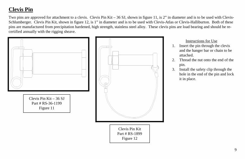
Two pins are approved for attachment to a clevis. Clevis Pin Kit – 36 SJ, shown in figure 11, is 2” in diameter and is to be used with Clevis-Schlumberger. Clevis Pin Kit, shown in figure 12, is 1” in diameter and is to be used with Clevis-Atlas or Clevis-Halliburton. Both of these pins are manufactured from precipitation hardened, high strength, stainless steel alloy. These clevis pins are load bearing and should be re-certified annually with the rigging sheave.
Instructions for Use
1. Insert the pin through the clevis and the hanger bar or chain to be attached.
2. Thread the nut onto the end of the pin.
3. Install the safety clip through the hole in the end of the pin and lock it in place.
Clevis Pin Kit – 36 SJ
Part # RS-36-1199 Figure 11
Clevis Pin Kit Part # RS-1899
Figure 12

10
Hanger Bar, Figure 13
Hanger Bar The hanger bar hangs from a crown block or elevator and provides a place to attach the rigging sheave. See figure 13. For use with Clevis-Schlumberger, order Part # SH-36-100, the hole (D) is 2.06”. For use with Clevis-Atlas or Clevis-Halliburton, order Part # SH-200, the hole (D) is 1.06”. The hanger bar is load bearing and should be re-certified annually with the rigging sheave.
Instructions for Use 1. Install the hanger bar in a safe position. 2. Line the holes in the clevis up with the
hole in the end of the hanger bar. 3. Insert an approved pin, shown on page
9, through the holes. 4. Properly lock the pin in place.

11
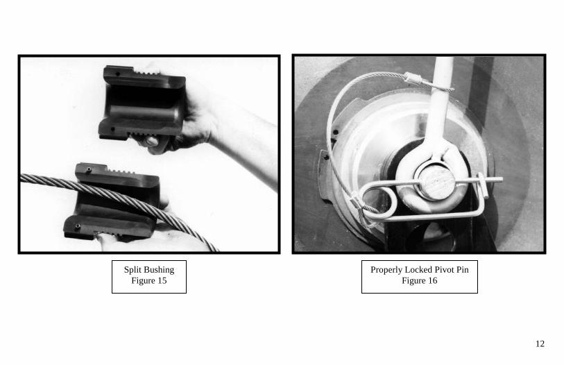
Hand Guard Perhaps the most important accessory to a rigging sheave is the hand guard. The hand guard helps prevent accidental entanglement of personnel into the sheave wheel. It is also very helpful at directing the line into the wheel groove to prevent jumping. See figure 14. A hole in the bushing allows the line to pass, but larger objects such as hands and clothing are stopped. The hand guard features split bushings and
e is not in use. See figure 15 on page 12.
Instructions for Use
slotted blocks so it installs quickly and can be left in place when the sheav
1. Remove the split bushings by unthreading them from the
blocks. 2. Install the arms on either side of the sheave so the holes in the
hinges line up with the holes in the axle shaft. 3. Insert the pivot pin through one of the hinges, then the axle,
and then the other hinge. 4. Thread the slotted nut onto the end of the pivot pin. 5. Install the safety clip through the hole in the pivot pin and lock
it in place. See figure 16 on page 12. 6. Pull the bushing apart then re-assemble them around the
wireline. See figure 15 on page 12. 7. Thread the bushings back into the blocks.
Maintenance ◊ Replace the split bushings if the holes wear close to the
threads. ◊ Lubricate the hinges with light machine oil to keep them
moving freely.
Hand Guard, Part # HG-36-100
Figure 14
12
Properly Locked Pivot Pin Figure 16
Split Bushing Figure 15

13
Floor Stand
The floor stand is used to keep the sheave upright and in position when the line is slack. Figure 17 shows a sheave mounted in a floor stand. A floor stand can be used with a hand guard. This floor stand, made for 32” and 36” sheaves, is heavy duty and is hinged so line can be loaded into the sheave after the floor stand has been attached. See figure 18.
32”/36” Floor Stand Part Number FS-36-100
Figure 17
Hinged Gate Figure 18

14
Instructions for Use 1. Stand the sheave on edge. 2. P heave’3. A ave’s ax4. I5. T6. Re e floor st7. O8. L des9. Cl hrough fr10. I lock it in p
lace the floor stand around the wheel with the hinged gate and slign the holes in the floor stand with the hole through the she
nstall the pivot pin through the holes. ip the floor stand upright. tract the pivot pin far enough to release the hinged side of th
pen the hinged side of the floor stand. See figure 18. oad the line onto the sheave wheel and secure the loading gate asose the hinged side of the floor stand and push the pivot pin t
nstall the safety clip through the hole in the end of the pin and
s gate on the same side. See figure 19. le.
and.
cribed on page 4. om the other side.
lace. See figure 20.
Properly Locked
Figure 20
Attaching the Floor Stand Figure 19

15
Rig-up Yoke
The rig-up yoke is used to carry the sheave and to stabilize it when in use. Figure 21 shows the yoke being used to carry the sheave. Figure 14 on page 11 shows the yoke being used to stabilize it when it is running. Never use it to anchor the sheave or apply load through it. It is designed to carry the weight of the sheave only and can be used with or without a hand guard
Instructions for Use
1. Install the yoke on either side of the shshaft. When used with a hand guardyoke.
2. Insert the pivot pin through the hole3. Install the safety clip through the ho
page 12. 4. Secure the yoke to hold the sheave in
Warnings
eave so the holes line up with the hole in the axle , position the hand guard arms inside of the rig-up
s and out the other side of the yoke. le in the pivot pin and lock it in place. See figure 16 on
the desired position.
• Never use the rig-up yoke as a substitu
• Never pull the sheave to the side withwireline.
•
te for the clevis. It is not designed to hold loads.
the rig-up yoke. Always keep it aligned with the
Never pull on the rig-up yoke harder than is required to hold the sheave in position. Rig-Up Yoke, Part # RY-36-100
Figure 21

16
Warranty For a period of one year from the date of purchase, Wireline Technologies, Inc., will repair or
replace, at its option, any 32” or 36” rigging sheave of its manufacture that fails because of a defect in materials or manufacture, or which fails to conform to any implied warranty not excluded herein. This warranty does not cover damages caused by abuse, misuse, neglect, or overloading; and does
not cover any incidental damages caused by a failure of this product.

17
Recertification and Repair Log Serial Number __________
Date Rec
ert
Rep
air
Performed by: Notes 1 1 1 1 1 1 1 1 1 1 1 1 1 1 1 1 1 1 1 1 1 1 1 1 1 1 1 1 1 1 1 1 1 1 1 1 1 1

18
Date Rec
ert
Rep
air
Performed by: Notes 1 1 1 1 1 1 1 1 1 1 1 1 1 1 1 1 1 1 1 1 1 1 1 1 1 1 1 1 1 1 1 1 1 1 1 1 1 1

19
Doc
. #W
TI-5
1 R
ev. 5
(28
Feb.
200
8)