Embed Size (px)
Citation preview
O n e C o m p a n y U n l i m i t e d S o l u t i o n s
Sta
ndard
and H
igh P
ressu
re W
irelin
e B
low
out P
reve
nte
rsWIRELINE BLOWOUT PREVENTERSInstruction Manual 8551
Standard and High PressureWireline Blowout PreventersGeneral Description ..................................................... 3Standard Model
Use .......................................................................... 3Operation ................................................................ 4Closing the Blowout Preventer ................................ 4Opening the Blowout preventer .............................. 6Maintenance............................................................ 7Disassembly of Blowout Preventer ......................... 7Disassembly of the Equalizer Valve ........................ 7Replacing Seals ...................................................... 8Replacing Non-Extrusion and
Seal Protector Rings............................................. 8Replacing Segment Rams ...................................... 9Reassembly ............................................................ 9Special Notes ........................................................ 10
Fail-Safe ModelUse ........................................................................ 11Construction .......................................................... 11Operation .............................................................. 12Maintenance.......................................................... 12
Hydraulic Hand Pump Assemblies .................... 13 – 14Specifications and Replacement Parts .............. 15 – 20
I N
D E
XWireline Blowout Preventers
The designs and specifications for the tools described in this
instruction manual were in effect at the time this manual was
approved for printing. National Oilwell, whose policy is one
of continuous improvement, reserves the right to discontinue
models at any time, or to change designs and specifications
without notice or without incurring obligation.
Sixteenth Printing, September 2003
3
Standard Model
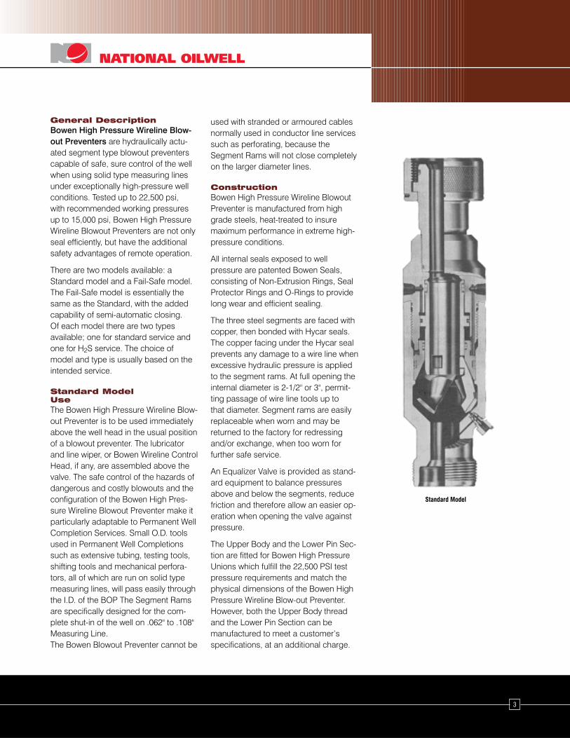
General DescriptionBowen High Pressure Wireline Blow-out Preventers are hydraulically actu-ated segment type blowout preventerscapable of safe, sure control of the wellwhen using solid type measuring linesunder exceptionally high-pressure wellconditions. Tested up to 22,500 psi,with recommended working pressuresup to 15,000 psi, Bowen High PressureWireline Blowout Preventers are not onlyseal efficiently, but have the additionalsafety advantages of remote operation.
There are two models available: aStandard model and a Fail-Safe model.The Fail-Safe model is essentially thesame as the Standard, with the addedcapability of semi-automatic closing.Of each model there are two typesavailable; one for standard service andone for H2S service. The choice ofmodel and type is usually based on theintended service.
Standard ModelUseThe Bowen High Pressure Wireline Blow-out Preventer is to be used immediatelyabove the well head in the usual positionof a blowout preventer. The lubricatorand line wiper, or Bowen Wireline ControlHead, if any, are assembled above thevalve. The safe control of the hazards ofdangerous and costly blowouts and theconfiguration of the Bowen High Pres-sure Wireline Blowout Preventer make itparticularly adaptable to Permanent WellCompletion Services. Small O.D. toolsused in Permanent Well Completionssuch as extensive tubing, testing tools,shifting tools and mechanical perfora-tors, all of which are run on solid typemeasuring lines, will pass easily throughthe I.D. of the BOP The Segment Ramsare specifically designed for the com-plete shut-in of the well on .062" to .108"Measuring Line.The Bowen Blowout Preventer cannot be
used with stranded or armoured cablesnormally used in conductor line servicessuch as perforating, because theSegment Rams will not close completelyon the larger diameter lines.
ConstructionBowen High Pressure Wireline BlowoutPreventer is manufactured from highgrade steels, heat-treated to insuremaximum performance in extreme high-pressure conditions.
All internal seals exposed to wellpressure are patented Bowen Seals,consisting of Non-Extrusion Rings, SealProtector Rings and O-Rings to providelong wear and efficient sealing.
The three steel segments are faced withcopper, then bonded with Hycar seals.The copper facing under the Hycar sealprevents any damage to a wire line whenexcessive hydraulic pressure is appliedto the segment rams. At full opening theinternal diameter is 2-1/2" or 3", permit-ting passage of wire line tools up tothat diameter. Segment rams are easilyreplaceable when worn and may bereturned to the factory for redressingand/or exchange, when too worn forfurther safe service.
An Equalizer Valve is provided as stand-ard equipment to balance pressuresabove and below the segments, reducefriction and therefore allow an easier op-eration when opening the valve againstpressure.
The Upper Body and the Lower Pin Sec-tion are fitted for Bowen High PressureUnions which fulfill the 22,500 PSI testpressure requirements and match thephysical dimensions of the Bowen HighPressure Wireline Blow-out Preventer.However, both the Upper Body threadand the Lower Pin Section can bemanufactured to meet a customer’sspecifications, at an additional charge.
4
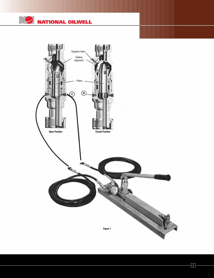
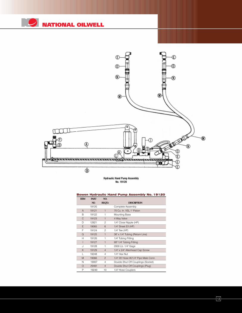
A necessary accessory for hand oper-ation is the complete Pump Assembly,No. 19120, or equivalent, consisting of ahydraulic pump, four way valve, pressuregage, two twenty foot long high-pressurehydraulic hoses, double shut-off quickcouplings and the necessary parts toconnect the assembly. It is also possibleto operate the Bowen High PressureWireline Blowout Preventer from thehydraulic system available in many WireLine Service trucks, or on the well site.
The hydraulic actuating system is com-pletely isolated from, and independent ofthe well pressures because of the BowenPatented Seal Ring Assemblies, consist-ing of a combination of Non-ExtrusionRings, Seal Protector and O-Rings.
On the Lower Body of the Bowen HighPressure Wireline Blowout Preventer arestenciled the words OPEN and CLOSEadjacent to the respective couplings.The Selector Valve, on the accessoryhand pump, is marked OPEN andCLOSE. These conveniences facilitateassembly and disassembly of the Blow-out Preventer hydraulic system in thefield and insure that the actuating systemis properly hooked up every time theBlowout Preventer is used.
OperationIt is recommended that the Bowen HighPressure Wireline Blowout Preventeralways be made-up to the well head andits operation observed, prior to raisingthe lubricator, while the Segment Ramsof the valve are still visible through theUpper Body.
When the Bowen High Pressure WirelineBlowout Preventer has been made-up tothe well head, connect one hydraulichose to the CLOSE coupling on the lowerportion of the main body and the otherhose to the OPEN coupling. (The mainbody is fitted with 1/4" high pressure
connections to which are assembled theplug halves of the quick connections.The hoses are equipped with the sockethalves of the quick connections at bothends of the hoses. The outlet sides of thefour way Selector valve on the pumpassembly are equipped with plug halvesof the quick connections.) Then connectthe hose connected to the PreventerCLOSE coupling to the CLOSE sideoutlet of the Selector Valve and the hoseconnected to the Preventer OPENcoupling to the OPEN side outlet.
Upon completion of this hook-up, turnthe Selector Valve to the CLOSE positionand operate the hand pump until ahydraulic pressure build-up is indicatedon the pressure gage. Look into the topof the Bowen High Pressure WirelineBlowout Preventer to see that the Seg-ment Rams have fully closed.
Next, turn the Selector Valve to the OPENposition; again operate the hand pumpuntil pressure is indicated on the pres-sure gage. Look into the top of theBowen High Pressure Wireline BlowoutPreventer to see that the Segment Ramsare now in the OPEN position.
When applying hydraulic hand pumppressure, do not build up excessivepressure. Use only enough pressure toeffect a complete seal.
After completing this observation proce-dure, check the level of the hydraulicfluid reservoir in the hydraulic pump andfill as necessary. In the initial installation,or first use of the system, it is sometimesnecessary to fill the hoses and thehydraulic reservoir of the Bowen BlowoutPreventer from the pump reservoir.There is adequate capacity in the pumpreservoir to accommodate all this andstill operate the system, but it is goodpolicy to maintain the system at its fullcapacity.
Following the test observations above,set the Selector Valve to the OPENposition and force the Segment Rams totheir full open position by operating thehand pump. Return the Selector Valve tothe Neutral or central position. Completethe well head set-up by raising thelubricator into position and securelymake up all unions, etc.
Closing theBlowout PreventerExamine the Equalizer Valve, (K) Figure2, mounted near the top of the UpperBody, to be sure that it is fully closed.(The Equalizer Valve stem is closed byturning to the right or clock-wise direc-tion.) Then the Selector Valve on thehand pump to the CLOSE position andoperate the hand pump.
Hydraulic fluid, under pressure, travelsfrom the pump, through the SelectorValve and the Hose into the Bowen HighPressure Wireline Blowout Preventer atpoint A, Figure 2. The hydraulic fluid,under pressure, fills the area (B) in theMain Body of the Valve. Since thehydraulic fluid is trapped between thePiston Seal (D) and the Piston Skirt Seal(C), it forces the Piston upward.
Because of the configuration of theinterior of the Upper Body (E) the GuideRing (F) and the Segment Rams (G),the Segments are forced together in auniform pressure tight seal as the Pistonmoves upward.
Well pressures, now trapped in theUpper Body by the Guide Ring InnerSeal (I) and the Guide Ring Outer Seal(H), act to close the Rams and perfectthe Outer Ram Seal (J) to the UpperBody. Pressure readings on the hydraulicpump gage are not indicative of wellpressures but simply provide the userwith a knowledge of the condition of thehydraulic system.
5
Figure 1
Closed PositionOpen Position
A M
Piston
Equalizer Valve
SealingSegments
6
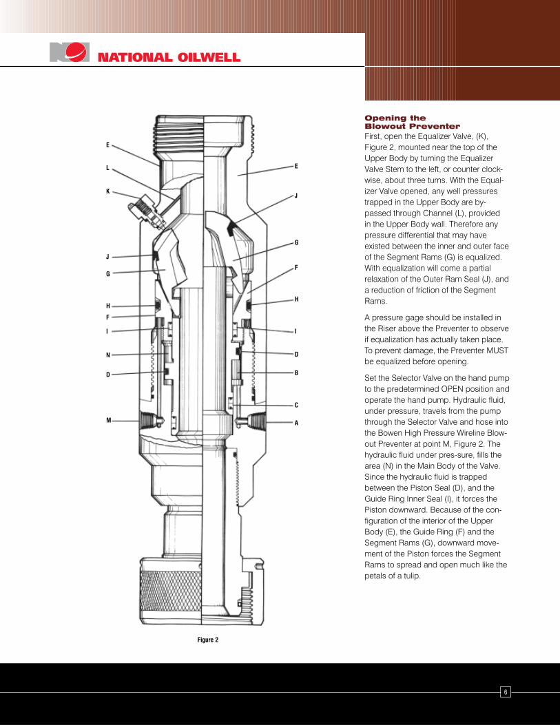
Opening theBlowout PreventerFirst, open the Equalizer Valve, (K),Figure 2, mounted near the top of theUpper Body by turning the EqualizerValve Stem to the left, or counter clock-wise, about three turns. With the Equal-izer Valve opened, any well pressurestrapped in the Upper Body are by-passed through Channel (L), providedin the Upper Body wall. Therefore anypressure differential that may haveexisted between the inner and outer faceof the Segment Rams (G) is equalized.With equalization will come a partialrelaxation of the Outer Ram Seal (J), anda reduction of friction of the SegmentRams.
A pressure gage should be installed inthe Riser above the Preventer to observeif equalization has actually taken place.To prevent damage, the Preventer MUSTbe equalized before opening.
Set the Selector Valve on the hand pumpto the predetermined OPEN position andoperate the hand pump. Hydraulic fluid,under pressure, travels from the pumpthrough the Selector Valve and hose intothe Bowen High Pressure Wireline Blow-out Preventer at point M, Figure 2. Thehydraulic fluid under pres-sure, fills thearea (N) in the Main Body of the Valve.Since the hydraulic fluid is trappedbetween the Piston Seal (D), and theGuide Ring Inner Seal (I), it forces thePiston downward. Because of the con-figuration of the interior of the UpperBody (E), the Guide Ring (F) and theSegment Rams (G), downward move-ment of the Piston forces the SegmentRams to spread and open much like thepetals of a tulip.
E
Figure 2
J
G
F
H
I
D
B
C
AM
D
N
I
H
F
J
G
K
L
E
7
12. Thoroughly clean and inspect allparts, particularly the seals, for anyevidence of advanced wear or dam-age. Repair or replace any worn ordamaged parts found. Oil all partsjust prior to reassembling them.
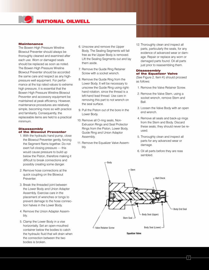
Disassemblyof the Equalizer Valve(See Figure 2, Item K) should proceedas follows:
1. Remove the Valve Retainer Screw.
2. Remove the Valve Stem, using asocket wrench, remove Stem andBall.
3. Loosen the Valve Body with an openend wrench.
4. Remove all seals and back-up ringsfrom the Stem and Body. Discardthese seals; they should never be re-used.
5. Thoroughly clean and inspect allparts for any advanced wear ordamage.
6. Oil all parts before they are reassembled.
MaintenanceThe Bowen High Pressure WirelineBlowout Preventer should always bethoroughly cleaned and examined aftereach use. Worn or damaged sealsshould be replaced as soon as noted.The Bowen High Pressure WirelineBlowout Preventer should be accordedthe same care and respect as any high-pressure well equipment. For perfor-mance at the top rated values to extremehigh pressure, it is essential that theBowen High Pressure Wireline BlowoutPreventer and accessory equipment bemaintained at peak efficiency. However,maintenance procedures are relativelysimple, becoming more so with practiceand familiarity. Consequently, thereplaceable items are held to a practicalminimum.
Disassemblyof the Blowout Preventer1. With the hydraulic hand pump, close
the Blowout Preventer gently, forcingthe Segment Rams together. Do notexert full closing pressure — thiswould cause pressure to build upbelow the Piston, therefore making itdifficult to break connections andpossibly creating some danger.
2. Remove hose connections at thequick coupling on the BlowoutPreventer.
3. Break the threaded joint betweenthe Lower Body and Union AdapterAssembly. Exercise care in theplacement of wrenches or tongs toprevent damage to the hose connec-tion halves in the Lower Body.
4. Remove the Union Adapter Assem-bly.
5. Clamp the Lower Body in a visehorizontally. Set an open-mouthedcontainer below the bodies to catchthe hydraulic fluid that will drain whenthe connection between the twobodies is broken.
6. Unscrew and remove the UpperBody. The Sealing Segments will fallfree as the Upper Body is removed.Lift the Sealing Segments out and laythem aside.
7. Remove the Guide Ring RetainerScrew with a socket wrench.
8. Remove the Guide Ring from theLower Body. It will be necessary tounscrew the Guide Ring using right-hand rotation, since the thread is aleft-hand lead thread. Use care inremoving this part to not wrench onthe seal surface.
9. Pull the Piston out of the bore in theLower Body.
10. Remove all O-ring seals, Non-Extrusion Rings and Seal ProtectorRings from the Piston, Lower Body,Guide Ring and Union AdaptorAssembly.
11. Remove the Equalizer Valve Assem-bly.
Equalizer Valve
Body End Seal
Body Seal (Lower)
Body Seal (Upper)
Ball Check
Stem
Body
Stem Seal
Valve Retainer Screw
Lower Body
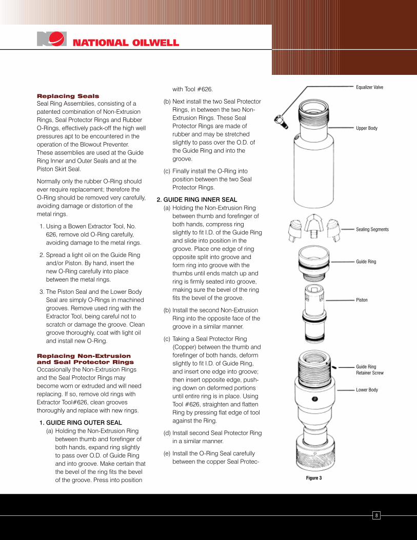
Figure 3
Guide RingRetainer Screw
Piston
Guide Ring
Sealing Segments
Upper Body
Equalizer Valve
8
Replacing SealsSeal Ring Assemblies, consisting of apatented combination of Non-ExtrusionRings, Seal Protector Rings and RubberO-Rings, effectively pack-off the high wellpressures apt to be encountered in theoperation of the Blowout Preventer.These assemblies are used at the GuideRing Inner and Outer Seals and at thePiston Skirt Seal.
Normally only the rubber O-Ring shouldever require replacement; therefore theO-Ring should be removed very carefully,avoiding damage or distortion of themetal rings.
1. Using a Bowen Extractor Tool, No.626, remove old O-Ring carefully,avoiding damage to the metal rings.
2. Spread a light oil on the Guide Ringand/or Piston. By hand, insert thenew O-Ring carefully into placebetween the metal rings.
3. The Piston Seal and the Lower BodySeal are simply O-Rings in machinedgrooves. Remove used ring with theExtractor Tool, being careful not toscratch or damage the groove. Cleangroove thoroughly, coat with light oiland install new O-Ring.
Replacing Non-Extrusionand Seal Protector RingsOccasionally the Non-Extrusion Ringsand the Seal Protector Rings maybecome worn or extruded and will needreplacing. If so, remove old rings withExtractor Tool#626, clean groovesthoroughly and replace with new rings.
1. GUIDE RING OUTER SEAL(a) Holding the Non-Extrusion Ring
between thumb and forefinger ofboth hands, expand ring slightlyto pass over O.D. of Guide Ringand into groove. Make certain thatthe bevel of the ring fits the bevelof the groove. Press into position
with Tool #626.
(b) Next install the two Seal ProtectorRings, in between the two Non-Extrusion Rings. These SealProtector Rings are made ofrubber and may be stretchedslightly to pass over the O.D. ofthe Guide Ring and into thegroove.
(c) Finally install the O-Ring intoposition between the two SealProtector Rings.
2. GUIDE RING INNER SEAL(a) Holding the Non-Extrusion Ring
between thumb and forefinger ofboth hands, compress ringslightly to fit I.D. of the Guide Ringand slide into position in thegroove. Place one edge of ringopposite split into groove andform ring into groove with thethumbs until ends match up andring is firmly seated into groove,making sure the bevel of the ringfits the bevel of the groove.
(b) Install the second Non-ExtrusionRing into the opposite face of thegroove in a similar manner.
(c) Taking a Seal Protector Ring(Copper) between the thumb andforefinger of both hands, deformslightly to fit I.D. of Guide Ring,and insert one edge into groove;then insert opposite edge, push-ing down on deformed portionsuntil entire ring is in place. UsingTool #626, straighten and flattenRing by pressing flat edge of toolagainst the Ring.
(d) Install second Seal Protector Ringin a similar manner.
(e) Install the O-Ring Seal carefullybetween the copper Seal Protec-
9
tor Rings.
(f) After the Seal Ring Assembliesare properly placed, use theGuide Ring Setting Tool to seatthe assembly. Drive the SettingTool into the bore of the GuideRing carefully to seat the copperProtector Rings. After the taperof the Setting Tool has passedthrough the Seal Assembly andis in full O.D. position, tap the toolwith the hammer around its peri-phery to set the rings.
3. PISTON SKIRT SEALThe seal assembly of the Piston Skirtconsists of two Non-Extrusion Rings,two rubber Seal Protector Rings andan O-Ring. Use the same Procedurefor replacement as in 1.
4. UPPER PIN SECTION SEALThe seal assembly on the upperportion of the Pin Section consists ofa Non-Extrusion Ring, a rubber SealProtection Ring and an O-Ring Seal.Follow replacement procedure 1.
5. LOWER PIN SECTION SEALThe lower Pin Section seal assemblyconsists of a Non-Extrusion Seal, arubber Seal Protection Ring and anO-Ring Seal. Use the same proce-dure for replacement as in 1 above.
Replacing Segment RamsThe old Segments were removed duringthe Disassembly Item 6 procedure.Examine them carefully for worn ordamaged seals both on the inner andouter faces. If worn or damaged, theSegments should be replaced.
Assemble the three replacementSegments together, then bind togetherwith a rubber band or light string foreasier installation. (Reassembly, Item 5).
NOTE: Segment Rams with worn or
damaged sealing faces may be returned to
National Oilwell for exchange or refacing.
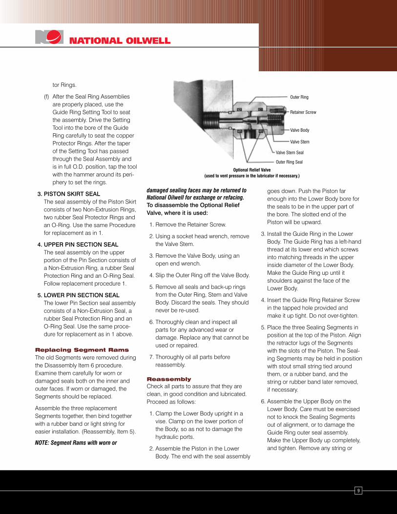
To disassemble the Optional ReliefValve, where it is used:
1. Remove the Retainer Screw.
2. Using a socket head wrench, removethe Valve Stem.
3. Remove the Valve Body, using anopen end wrench.
4. Slip the Outer Ring off the Valve Body.
5. Remove all seals and back-up ringsfrom the Outer Ring, Stem and ValveBody. Discard the seals. They shouldnever be re-used.
6. Thoroughly clean and inspect allparts for any advanced wear ordamage. Replace any that cannot beused or repaired.
7. Thoroughly oil all parts beforereassembly.
ReassemblyCheck all parts to assure that they areclean, in good condition and lubricated.Proceed as follows:
1. Clamp the Lower Body upright in avise. Clamp on the lower portion ofthe Body, so as not to damage thehydraulic ports.
2. Assemble the Piston in the LowerBody. The end with the seal assembly
Optional Relief Valve(used to vent pressure in the lubricator if necessary.)
Outer Ring
Retainer Screw
Valve Body
Valve Stem
Valve Stem Seal
Outer Ring Seal
goes down. Push the Piston farenough into the Lower Body bore forthe seals to be in the upper part ofthe bore. The slotted end of thePiston will be upward.
3. Install the Guide Ring in the LowerBody. The Guide Ring has a left-handthread at its lower end which screwsinto matching threads in the upperinside diameter of the Lower Body.Make the Guide Ring up until itshoulders against the face of theLower Body.
4. Insert the Guide Ring Retainer Screwin the tapped hole provided andmake it up tight. Do not over-tighten.
5. Place the three Sealing Segments inposition at the top of the Piston. Alignthe retractor lugs of the Segmentswith the slots of the Piston. The Seal-ing Segments may be held in positionwith stout small string tied aroundthem, or a rubber band, and thestring or rubber band later removed,if necessary.
6. Assemble the Upper Body on theLower Body. Care must be exercisednot to knock the Sealing Segmentsout of alignment, or to damage theGuide Ring outer seal assembly.Make the Upper Body up completely,and tighten. Remove any string or
10
rubber band from the Sealing Seg-ments, if used.
7. Connect the Hydraulic Hand PumpAssembly to the Blowout Preventer,and test its operation, as describedunder Test Procedure, above.
8. After proper operation of the BlowoutPreventer is assured the UnionAdaptor Assembly may be assem-bled into the lower end of the LowerBody, and make up tight.
9. Complete the assembly procedure byreassembling the Equalizer Valve andinserting it in the Body.
To Assemble the Equalizer Valve,proceed as follows:
1. Assemble the Seals and back-uprings in the Outer Rings.
2. Assemble the Seals and back-uprings on the Connector Tube.
3. Insert the Valve Body and the By-Pass Body into the Outer Rings.
4. Insert the Connector Tube into thetwo Outer Rings in the two holesprovided.
5. Screw the By-Pass Body and ValveBody into the Blowout PreventerBody, taking care to get the By-PassBody in the upper port (above theram bore) and the Valve Body in thelower position. Screw both bodies inplace simultaneously, and make themtight.
6. Assemble the Seal and back-up ringon the Valve Stem, and insert the BallCheck and Valve Stem into the ValveBody. Using a socket wrench, screwthe Valve Stem in until it seats.
7. Screw the Retainer Screw into theValve Body until it is snug.
The Optional Relief Valve may beassembled as follows:
1. Insert the Seals and back-up rings inthe Outer Ring.
2. Assemble the Valve Stem into theOuter Ring.
3. Assemble the Seal and back-up ringon the Valve Stem.
4. Screw the Valve Stem into the ValveBody, until it seats.
5. Screw the Retainer Screw into theValve Body until it is snug.
6. When this Relief Valve is ordered, theUpper Body of the preventer isprovided with a tapped hole throughthe neck near the upper connection.Install the assembled optional ReliefValve in that hole.
Special Notes1. Some models of the Bowen High
Pressure Blowout Preventer varyslightly in design from the 35196assembly described above. In parti-cular, older models have a LowerBody and Guide Ring which do notthread together; they are heldtogether by three Guide Ring RetainerScrews instead of only one. Caremust be exercised when assemblingor disassembling these models, tocheck the Specifications and Replace-ment Parts list on page 12, to acquaintthe operator with the variations indesign of the particular assemblybeing dressed.
2. Seals should never be re-used whenin poor condition or when very cold.Whenever the operator doubts theircondition they should be replaced.
The Sealing Segments, when tooworn for safe service, may bereturned to National Oilwell forremolding, provided that only therubber portion is worn or damaged.
3. A Hydraulic Hand Pump Repair kit isavailable from National Oilwell. This isshown on page ?. This kit containsall the necessary small parts tocompletely recondition the HandPump, when ordinary wear makesthis desirable.
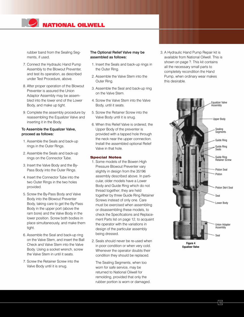
Figure 4Equalizer Valve
Union AdapterAssembly
Seal
Lower Body
Piston Seal
Piston
Piston Skirt Seal
Seal
Guide Ring
Guide RingSeals
Guide RingRetainer Screw
SealingSegments
Upper Body
Equalizer ValveAssembly
11
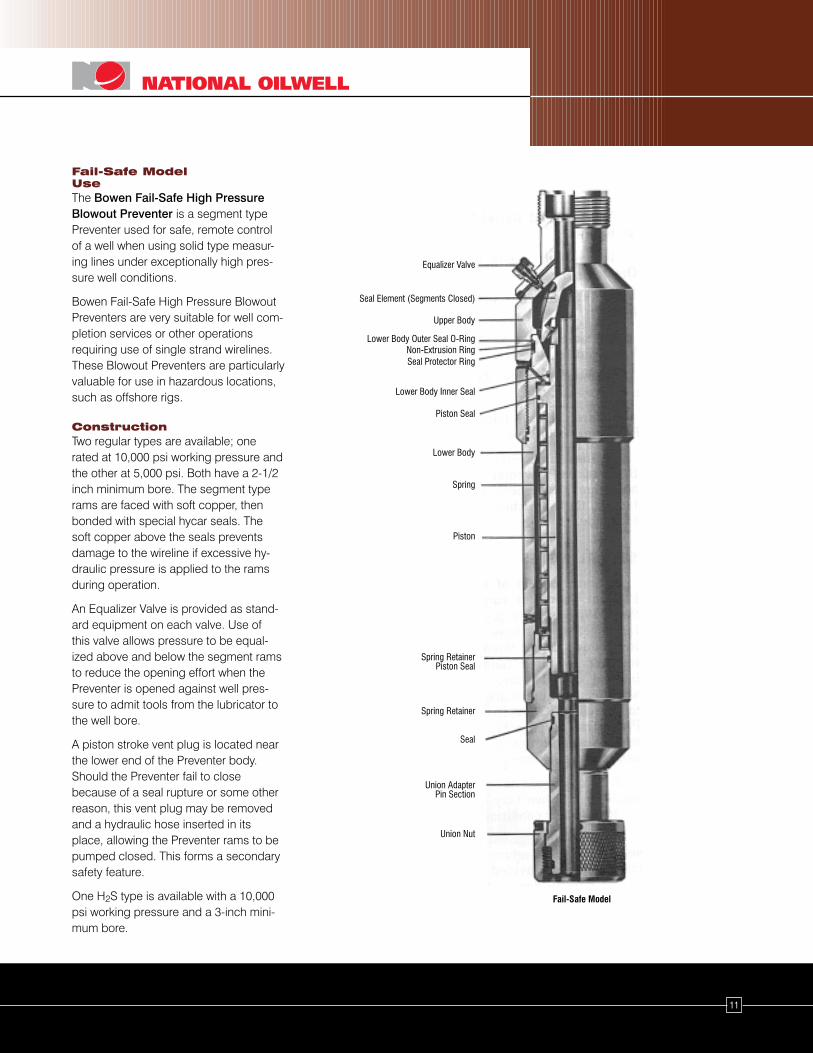
Fail-Safe ModelUseThe Bowen Fail-Safe High PressureBlowout Preventer is a segment typePreventer used for safe, remote controlof a well when using solid type measur-ing lines under exceptionally high pres-sure well conditions.
Bowen Fail-Safe High Pressure BlowoutPreventers are very suitable for well com-pletion services or other operationsrequiring use of single strand wirelines.These Blowout Preventers are particularlyvaluable for use in hazardous locations,such as offshore rigs.
ConstructionTwo regular types are available; onerated at 10,000 psi working pressure andthe other at 5,000 psi. Both have a 2-1/2inch minimum bore. The segment typerams are faced with soft copper, thenbonded with special hycar seals. Thesoft copper above the seals preventsdamage to the wireline if excessive hy-draulic pressure is applied to the ramsduring operation.
An Equalizer Valve is provided as stand-ard equipment on each valve. Use ofthis valve allows pressure to be equal-ized above and below the segment ramsto reduce the opening effort when thePreventer is opened against well pres-sure to admit tools from the lubricator tothe well bore.
A piston stroke vent plug is located nearthe lower end of the Preventer body.Should the Preventer fail to closebecause of a seal rupture or some otherreason, this vent plug may be removedand a hydraulic hose inserted in itsplace, allowing the Preventer rams to bepumped closed. This forms a secondarysafety feature.
One H2S type is available with a 10,000psi working pressure and a 3-inch mini-mum bore.
Fail-Safe Model
Equalizer Valve
Seal Element (Segments Closed)
Upper Body
Seal Protector Ring
Lower Body Inner Seal
Piston Seal
Lower Body Outer Seal O-Ring
Lower Body
Non-Extrusion Ring
Spring
Piston
Spring RetainerPiston Seal
Spring Retainer
Seal
Union Nut
Union AdapterPin Section
OperationIn operation, the Preventer is locatedbelow the Lubricator on the well head asusual. The Preventer will be closed untildeliberately opened.
The Lubricator is opened at the top, thetools and wire line admitted, after whichthe line wiper, stuffing box or otherterminal seal is closed. Pressure is thenequalized between the lubricator and thewell by means of the integral EqualizerValve on the Blowout Preventer.
To admit tools to the well bore, hydraulicpressure is pumped into the upper portof the Blowout Preventer. This may bedone by use of a simple Bowen Hydrau-lic Hand Pump or by use of availablerig hydraulics. No more than 1,200 psihydraulic pressure will be required toeffect complete opening.
Hydraulic pressure must be maintainedto the opening port of the Preventer dur-ing the entire operation or for so longas the operator wants the Preventer toremain open. Should the hydraulic hoserupture or the hydraulic pressure to thePreventer otherwise fail, the Preventer willautomatically close.
In service, the Preventer is opened byhydraulic pressure. To close, the hydrau-lic pressure is relieved and the Preventerwill close itself automatically by means ofa heavy spring incorporated in the bodyof the tool and acting directly againstthe closing piston. The spring is assistedand reinforced by a differential areaarrangement of the piston which utilizesany existing well pressure as a positiveclosing force.
The closing operation is very rapid.Once the opening hydraulic pressure isrelieved, either deliberately or by acci-dentally rupturing the hydraulic hose,the Preventer will close almost instanta-neously when high well pressure ispresent. With no pressure on the well,the Preventer will close completely withintwo and one-half seconds.
MaintenanceThe Bowen Fail-Safe High PressureBlowout Preventer is so much like theStandard model that maintenance isalmost identical. The main difference isthat the Fail-Safe model is longer andprovided with a cavity under the Piston inwhich the Spring is housed. Disassemblyand assembly would be the same exceptfor that spring. So, for maintenance ofthe Fail- Safe model, use the proceduredescribed for the Standard model begin-ning on page 3.
12
13
Bowen Hydraulic Hand Pump Assembly No. 19120ITEM PART NO.
NO. REQ’D. DESCRIPTION
19120 Complete Assembly
A 19121 1 70 Cu. In. VSL 1" Piston
B 19122 1 Mounting Base
C 19123 1 4 Way Valve
D 12821 2 1/4" Close Nipple (HP)
E 19065 6 1/4" Street Ell (HP)
F 19124 2 1/4" Tee (HP)
G 19125 1 36" x 1/4" Tubing (Return Line)
H 19126 1 1/4" Tubing Fitting
I 19127 1 900 1/4" Tubing Fitting
J 19128 1 2000 Lb. 1/4" Gage
K 19129 4 1/4" x 3/4" Allenhead Cap Screw
L 19248 4 1/4" Hex Nut
M 19066 2 1/4" 20' Hose W/1/4" Pipe Male Conn.
N 19067 4 Double Shut Off Couplings (Socket)
O 29481 4 Double Shut Off Couplings (Plug)
P 19249 10 1/4" Hose Couplers
Hydraulic Hand Pump AssemblyNo. 19120
14
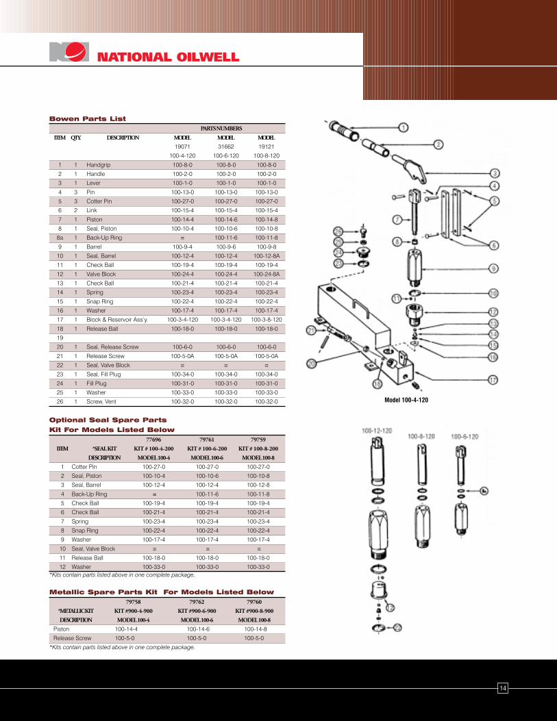
Bowen Parts ListPARTS NUMBERS
ITEM QTY. DESCRIPTION MODEL MODEL MODEL
19071 31662 19121
100-4-120 100-6-120 100-8-120
1 1 Handgrip 100-8-0 100-8-0 100-8-0
2 1 Handle 100-2-0 100-2-0 100-2-0
3 1 Lever 100-1-0 100-1-0 100-1-0
4 3 Pin 100-13-0 100-13-0 100-13-0
5 3 Cotter Pin 100-27-0 100-27-0 100-27-0
6 2 Link 100-15-4 100-15-4 100-15-4
7 1 Piston 100-14-4 100-14-6 100-14-8
8 1 Seal, Piston 100-10-4 100-10-6 100-10-8
8a 1 Back-Up Ring ≡ 100-11-6 100-11-8
9 1 Barrel 100-9-4 100-9-6 100-9-8
10 1 Seal, Barrel 100-12-4 100-12-4 100-12-8A
11 1 Check Ball 100-19-4 100-19-4 100-19-4
12 1 Valve Block 100-24-4 100-24-4 100-24-8A
13 1 Check Ball 100-21-4 100-21-4 100-21-4
14 1 Spring 100-23-4 100-23-4 100-23-4
15 1 Snap Ring 100-22-4 100-22-4 100-22-4
16 1 Washer 100-17-4 100-17-4 100-17-4
17 1 Block & Reservoir Ass’y. 100-3-4-120 100-3-4-120 100-3-8-120
18 1 Release Ball 100-18-0 100-18-0 100-18-0
19
20 1 Seal, Release Screw 100-6-0 100-6-0 100-6-0
21 1 Release Screw 100-5-0A 100-5-0A 100-5-0A
22 1 Seal, Valve Block ≡ ≡ ≡23 1 Seal, Fill Plug 100-34-0 100-34-0 100-34-0
24 1 Fill Plug 100-31-0 100-31-0 100-31-0
25 1 Washer 100-33-0 100-33-0 100-33-0
26 1 Screw, Vent 100-32-0 100-32-0 100-32-0
Optional Seal Spare Parts
Kit For Models Listed Below77696 79761 79759
ITEM *SEAL KIT KIT # 100-4-200 KIT # 100-6-200 KIT # 100-8-200
DESCRIPTION MODEL 100-4 MODEL 100-6 MODEL 100-8
1 Cotter Pin 100-27-0 100-27-0 100-27-0
2 Seal, Piston 100-10-4 100-10-6 100-10-8
3 Seal, Barrel 100-12-4 100-12-4 100-12-8
4 Back-Up Ring ≡ 100-11-6 100-11-8
5 Check Ball 100-19-4 100-19-4 100-19-4
6 Check Ball 100-21-4 100-21-4 100-21-4
7 Spring 100-23-4 100-23-4 100-23-4
8 Snap Ring 100-22-4 100-22-4 100-22-4
9 Washer 100-17-4 100-17-4 100-17-4
10 Seal, Valve Block ≡ ≡ ≡11 Release Ball 100-18-0 100-18-0 100-18-0
12 Washer 100-33-0 100-33-0 100-33-0*Kits contain parts listed above in one complete package.
Metallic Spare Parts Kit For Models Listed Below79758 79762 79760
*METALLIC KIT KIT #900-4-900 KIT #900-6-900 KIT #900-8-900
DESCRIPTION MODEL 100-4 MODEL 100-6 MODEL 100-8
Piston 100-14-4 100-14-6 100-14-8
Release Screw 100-5-0 100-5-0 100-5-0
*Kits contain parts listed above in one complete package.
Model 100-4-120
15
Bowen Standard High Pressure Wireline Blowout PreventersInternal Diameter (Inches) 2-1/2 2-1/2 3
Body O.D. (Inches) 7 8-1/2 8-1/2
Test Pressure - P.S.I. 15,000 22,500 15,000
Working Pressure - P.S.I. 10,000 15,000 10,000
Complete Assembly Part No. 35196 29940 34455
Weight 220 285 305
Replacement Parts Part No. 18636 29941 34456
Upper Body Weight 88 120 115
Part No. 34767 29942 34457
Lower Body Weight 82 105 102
Part No. 18638 29943 34458
Piston Weight 8 10 15
Part No. 34766 29944 34459
Guide Ring Weight 6 7 9
Guide Ring Part No. 34768 35273 34765
Set Screw No. Req’d 1 1 1
Sealing Element Part No. 18105 18105 37685
Set (3 Segments) Weight 6 6 15
Bowen Union Part No. 18618 29952 34464
Adaptor Assembly Weight 25 35 45
Equalizer Valve Part No. 69187 70076 69187
Assembly Weight 1/2 1 1/2
Lower Body Seal Part No. 30-31 30-35 30-40
(Large) Weight 1/16 1/16 1/16
Lower Body Seal Part No. ≡ 30-31 30-38
(Small) Weight ≡ 1/16 1/16
Part No. 27-47 27-49 27-55
Piston Seal Weight 1/32 1/32 1/16
Part No. 146427 71791 146459
Piston Skirt Seal Weight 1/8 1/8 1/8
Guide Ring Part No. 146428 71789 146460
Inner Seal Weight 1/32 1/32 1/16
Complete Assembly Part No. 35196 29940 34455
Replacement Parts (Continued)Guide Ring Outer
Non-extrusion Part No. 216-54 216-56 216-64
Ring (2 Req’d.) Weight 1/8 1/16 1/16
Guide Ring Outer
Seal Protector Part No. 227-54 227-56 227-64
Ring (2 Req’d.) Weight 1/16 1/16 1/16
Guide Ring Part No. 27-54 27-56 27-64
Outer Seal Weight 1/8 1/8 1/8
Bowen Union Adapters Consisting of: Part No. 18618 29952 34464
Assembly Number Weight 28 42 45
Part No. 18619 29945 34465
Pin Section Weight 20 33 30
Upper Non- Part No. 216-41 216-43 216-48
Extrusion Ring Weight 1/16 1/16 1/16
Upper Seal Part No. 227-41 227-43 227-48
Protector Ring Weight 1/16 1/16 1/16
Upper Pin Part No. 27-41 27-43 27-48
Section Seal Weight 1/16 1/16 1/16
Lower Non- Part No. 216-43 216-48 216-60
Extrusion Ring Weight 1/16 1/16 1/16
Lower Seal Part No. 227-43 227-48 227-60
Protector Ring Weight 1/16 1/16 1/16
Lower Pin Part No. 27-43 27-48 27-60
Section Seal Weight 1/16 1/16 1/16
Part No. 17888 29921 22553
Retainer Nut Weight 7 9 14
Bowen Equalizer Valve Assembly Consisting of: Part No. 69187 70076 69187
Assembly Number Weight 3/4 1 3/4
Part No. 68620 69897 68620
Body Weight 1/4 3/8 1/4
How To Order: Recommended Spares:Specify: (1) Name and Number of Assembly or Part. (1) 2 Sets Sealing Elements.
(2) Connections, if other than Standard. (2) 4 Complete ‘O’ Ring Packing Sets.(3) Any Spares desired, by Name and Number. (3) 1 of Each Non-Extrusion Ring.
(4) 1 of Each Seal Protector Ring.
16
Complete
Assembly Part No. 35196 29940 34455
Optional (Continued)Packing Set Part No. 72523* 72524* ≡(Gas Resisting) Weight 1/2 1/2 ≡
Safety Seal Assembly Consisting of:Assembly Part No. 46599 ≡ 46599
Number Weight 6-1/2 ≡ 6-1/2
Part No. 56600 ≡ 46600
Housing Weight 6 ≡ 6
Adjusting Part No. 46601 ≡ 46601
Screw Weight 1/16 ≡ 1/16
Part No. 46604 ≡ 46604
Lead Seal Weight 3/8 ≡ 3/8
Optional Bowen Union Adapter Consisting of:Assembly Part No. 18615 ≡ 62702
Number Weight 30 ≡ 33
Upper Pin Part No. 27-41 ≡ 27-48
Section Seal Weight 1/16 ≡ 1/16
Non-extrusion Part No. 216-41 ≡ 216-48
Ring (Upper) Weight 1/8 ≡ 1/8
Seal Protector Part No. 227-41 ≡ 227-48
Ring (Upper) Weight 1/16 ≡ 1/16
Lower Pin Part No. 27-48 ≡ 27-48
Section Seal Weight 1/16 ≡ 1/16
Non-extrusion Part No. 216-48 ≡ 216-48
Ring (Lower) Weight 1/8 ≡ 1/8
Seal Protector Part No. 227-48 ≡ 227-48
Ring (Lower) Weight 1/16 ≡ 1/16
Part No. 18616 ≡ 62703
Pin Section Weight 22 ≡ 25
Part No. 17883 ≡ 17883
Retainer Nut Weight 7 ≡ 7
Bowen Standard High Pressure Wireline Blowout
Preventers (Continued)Complete
Assembly Part No. 35196 29940 34455
Bowen Equalizer Valve Assembly
Consisting of: (Continued) Part No. 68998 70076 68998
Stem Weight 1/8 1/4 1/8
Large Body Seal Part No. 27-12 27-12 27-12
(Upper) Weight 1/32 1/32 1/32
Part No. 68145 68145 68145
Ball Check Weight 1/16 1/16 1/16
Small Body Seal Part No. 568-013 568-013 568-013
(Lower) Weight 1/32 1/32 1/32
Part No. 27-4 27-4 27-4
Stem Seal Weight 1/32 1/32 1/32
Stem Retainer Part No. 9558 9558 9558
Screw Weight 1/16 1/16 1/16
Part No. 27-5 27-5 27-5
Body End Seal Weight 1/16 1/16 1/16
Required AccessoriesSeal Extractor Part No. 626 626 626
Tool Weight 1/2 1/2 1/2
OptionalHydraulic Part No. 19120 19120 19120
Hand Pump Weight 41 41 41
Relief Valve Part No. 15834 ≡ 15834
Assembly Weight 1/4 ≡ 1/4
Sealing Segments Part No. 29508 29508 37690
(Set Of 3 Molded Weight ≡ ≡ 15
Urethane)
“O” Ring Comp. Part No. 72520* 72521* 72522*
Packing Set Weight 1/4 1/4 1/4
Hose Connection Part No. 20522 ≡ 20522
Protector Ring Weight 2 ≡ 2
Part No. 21648 ≡ 34499
Lifting Clamp Weight 4 ≡ 8
How To Order : Recommended Spares:Specify: (1) Name and Number of Assembly or Part. (1) 2 Sets Sealing Elements.
(2) Connections, if other than Standard. (2) 4 Complete ‘O’ Ring Packing Sets.(3) Any Spares desired, by Name and Number. (3) 1 of Each Non-Extrusion Ring.
*(4) When ordering Packing Set determine if segment B.O.P. uses “O” -Rings, (4) 1 of Each Seal Protector Ring.Non-Extrusion Rings and Seal Protector Rings on Piston and Guide Ring.If so, specify this on order. The Packing Set Nos. listed are for newstyle seals (Poly Pak and Shamban). Numbers are listed on parts listsfor old style.
17
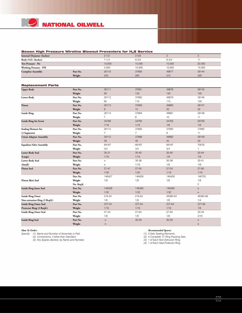
Bowen High Pressure Wireline Blowout Preventers for H2S ServiceInternal Diameter (Inches) 2-1/2 2-5/8 3 3
Body O.D. (Inches) 7-1/4 8-3/4 9-3/4 11
Test Pressure - Psi 10,000 15,000 15,000 22,500
Working Pressure - PSI 5,000 10,000 10,000 15,000
Complete Assembly Part No. 26110 37680 49877 58144
Weight 240 295 310 320
Replacement PartsUpper Body Part No. 26111 37681 49878 58145
Weight 90 130 140 150
Lower Body Part No. 26112 37682 49879 58146
Weight 85 110 115 120
Piston Part No. 26113 37683 49880 58147
Weight 9 15 20 22
Guide Ring Part No. 26114 37684 49881 58148
Weight 7 8 10 11
Guide Ring Set Screw Part No. 34768 34765 34765 59759
Weight 1/16 1/16 1/8 1/8
Sealing Element Set Part No. 26115 37685 37685 37685
(3 Segments) Weight 7 7 9 11
Union Adaptor Assembly Part No. 29112 37686 49882 58149
Weight 28 40 45 50
Equalizer Valve Assembly Part No. 69187 69187 69187 70076
Weight 3/4 3/4 3/4 1
Lower Body Seal Part No. 30-31 30-40 30-40 30-44
(Large) Weight 1/16 1/16 1/8 1/8
Lower Body Seal Part No. ≡ 30-38 30-38 30-41
(Small) Weight ≡ 1/16 1/8 1/8
Piston Seal Part No. 27-47 27-55 27-55 27-60
Weight 1/32 1/32 1/16 1/16
Part No. 146427 146459 146459 146705
Piston Skirt Seal Weight 1/8 1/8 1/8 1/8
No. Req’d. 2
Guide Ring Inner Seal Part No. 146428 146460 146460 ≡ Weight 1/32 1/32 1/32 ≡
Guide Ring Outer Part No. 216-54 216-64 46380-64 46380-66
Non-extrusion Ring (2 Req’d.) Weight 1/8 1/8 1/8 1/4
Guide Ring Outer Seal Part No. 227-54 227-64 227-64 227-66
Protector Ring (2 Req’d.) Weight 1/16 1/16 1/16 1/8
Guide Ring Outer Seal Part No. 27-54 27-64 27-64 30-34
Weight 1/8 1/8 1/8 3/16
Guide Ring Seal Part No. ≡ 30-29 30-29 ≡ Weight ≡ ≡
How To Order: Recommended Spares:Specify: (1) Name and Number of Assembly or Part. (1) 2 Sets Sealing Elements.
(2) Connections, if other than Standard. (2) 4 Complete ‘O’ Ring Packing Sets.(3) Any Spares desired, by Name and Number. (3) 1 of Each Non-Extrusion Ring.
(4) 1 of Each Seal Protector Ring.
18
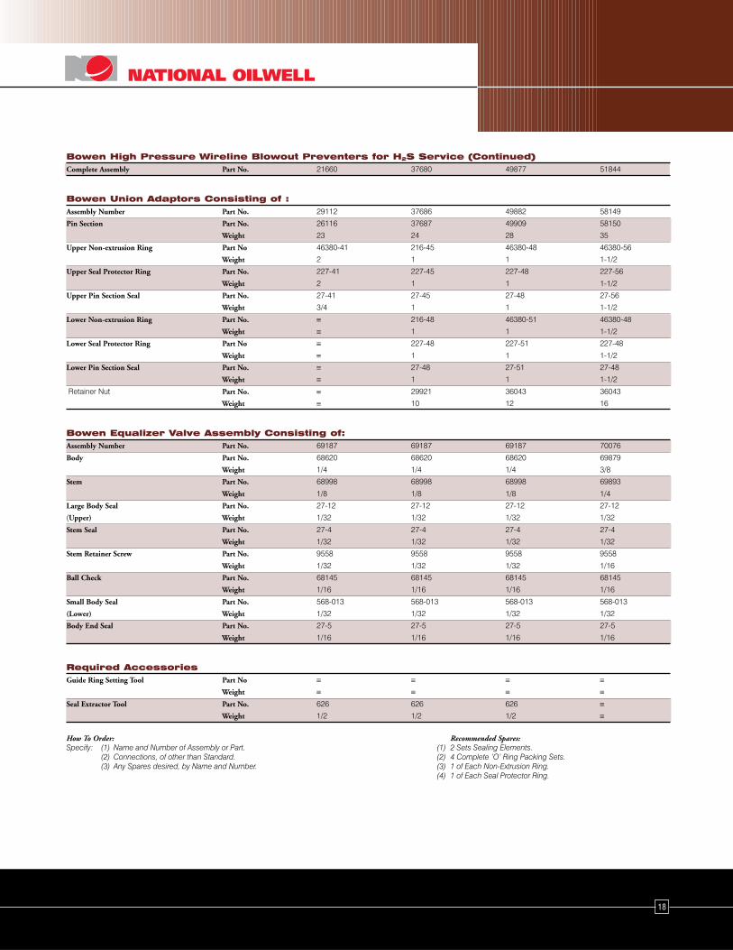
Bowen High Pressure Wireline Blowout Preventers for H2S Service (Continued)Complete Assembly Part No. 21660 37680 49877 51844
Bowen Union Adaptors Consisting of :Assembly Number Part No. 29112 37686 49882 58149
Pin Section Part No. 26116 37687 49909 58150
Weight 23 24 28 35
Upper Non-extrusion Ring Part No 46380-41 216-45 46380-48 46380-56
Weight 2 1 1 1-1/2
Upper Seal Protector Ring Part No. 227-41 227-45 227-48 227-56
Weight 2 1 1 1-1/2
Upper Pin Section Seal Part No. 27-41 27-45 27-48 27-56
Weight 3/4 1 1 1-1/2
Lower Non-extrusion Ring Part No. ≡ 216-48 46380-51 46380-48
Weight ≡ 1 1 1-1/2
Lower Seal Protector Ring Part No ≡ 227-48 227-51 227-48
Weight ≡ 1 1 1-1/2
Lower Pin Section Seal Part No. ≡ 27-48 27-51 27-48
Weight ≡ 1 1 1-1/2
Retainer Nut Part No. ≡ 29921 36043 36043
Weight ≡ 10 12 16
Bowen Equalizer Valve Assembly Consisting of:Assembly Number Part No. 69187 69187 69187 70076
Body Part No. 68620 68620 68620 69879
Weight 1/4 1/4 1/4 3/8
Stem Part No. 68998 68998 68998 69893
Weight 1/8 1/8 1/8 1/4
Large Body Seal Part No. 27-12 27-12 27-12 27-12
(Upper) Weight 1/32 1/32 1/32 1/32
Stem Seal Part No. 27-4 27-4 27-4 27-4
Weight 1/32 1/32 1/32 1/32
Stem Retainer Screw Part No. 9558 9558 9558 9558
Weight 1/32 1/32 1/32 1/16
Ball Check Part No. 68145 68145 68145 68145
Weight 1/16 1/16 1/16 1/16
Small Body Seal Part No. 568-013 568-013 568-013 568-013
(Lower) Weight 1/32 1/32 1/32 1/32
Body End Seal Part No. 27-5 27-5 27-5 27-5
Weight 1/16 1/16 1/16 1/16
Required AccessoriesGuide Ring Setting Tool Part No ≡ ≡ ≡ ≡
Weight ≡ ≡ ≡ ≡Seal Extractor Tool Part No. 626 626 626 ≡
Weight 1/2 1/2 1/2 ≡
How To Order: Recommended Spares:Specify: (1) Name and Number of Assembly or Part. (1) 2 Sets Sealing Elements.
(2) Connections, of other than Standard. (2) 4 Complete ‘O’ Ring Packing Sets.(3) Any Spares desired, by Name and Number. (3) 1 of Each Non-Extrusion Ring.
(4) 1 of Each Seal Protector Ring.
19
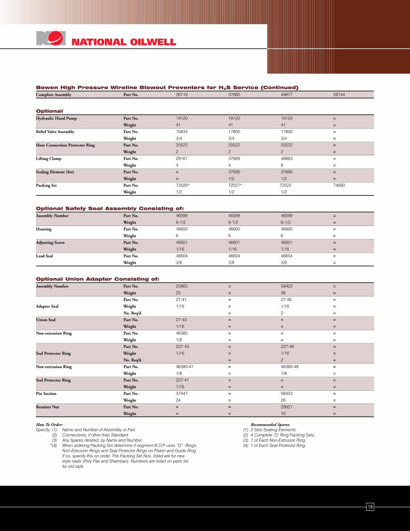
Bowen High Pressure Wireline Blowout Preventers for H2S Service (Continued)Complete Assembly Part No. 26110 37680 49877 58144
OptionalHydraulic Hand Pump Part No. 19120 19120 19120 ≡
Weight 41 41 41 ≡Relief Valve Assembly Part No. 15834 17800 17800 ≡
Weight 3/4 3/4 3/4 ≡Hose Connection Protector Ring Part No. 20522 20522 20522 ≡
Weight 2 2 2 ≡Lifting Clamp Part No. 29161 37689 49883 ≡
Weight 4 4 8 ≡Sealing Element (Set) Part No. ≡ 37690 37690 ≡
Weight ≡ 1/2 1/2 ≡Packing Set Part No. 72526* 72527* 72522 74690
Weight 1/2 1/2 1/2
Optional Safety Seal Assembly Consisting of:Assembly Number Part No. 46599 46599 46599 ≡
Weight 6-1/2 6-1/2 6-1/2 ≡Housing Part No. 46600 46600 46600 ≡
Weight 6 6 6 ≡Adjusting Screw Part No. 46601 46601 46601 ≡
Weight 1/16 1/16 1/16 ≡Lead Seal Part No. 46604 46604 46604 ≡
Weight 3/8 3/8 3/8 ≡
Optional Union Adapter Consisting of:Assembly Number Part No. 25865 ≡ 58422 ≡
Weight 25 ≡ 38 ≡ Part No. 27-41 ≡ 27-48 ≡
Adapter Seal Weight 1/16 ≡ 1/16 ≡ No. Req’d. ≡ 2 ≡
Union Seal Part No. 27-43 ≡ ≡ ≡ Weight 1/16 ≡ ≡ ≡
Non-extrusion Ring Part No. 46380 ≡ ≡ ≡ Weight 1/8 ≡ ≡ ≡ Part No. 227-43 ≡ 227-48 ≡
Seal Protector Ring Weight 1/16 ≡ 1/16 ≡ No. Req’d. ≡ 2 ≡
Non-extrusion Ring Part No. 46380-41 ≡ 46380-48 ≡ Weight 1/8 ≡ 1/8 ≡
Seal Protector Ring Part No. 227-41 ≡ ≡ ≡ Weight 1/16 ≡ ≡ ≡
Pin Section Part No. 37447 ≡ 58423 ≡ Weight 24 ≡ 26 ≡
Retainer Nut Part No. ≡ ≡ 29921 ≡ Weight ≡ ≡ 10 ≡
How To Order: Recommended Spares:Specify: (1) Name and Number of Assembly or Part. (1) 2 Sets Sealing Elements.
(2) Connections, if other than Standard. (2) 4 Complete ‘O’ Ring Packing Sets.(3) Any Spares desired, by Name and Number. (3) 1 of Each Non-Extrusion Ring.
*(4) When ordering Packing Set determine if segment B.O.P. uses “O” -Rings, (4) 1 of Each Seal Protector Ring.Non-Extrusion Rings and Seal Protector Rings on Piston and Guide Ring.If so, specify this on order. The Packing Set Nos. listed are for newstyle seals (Poly Pak and Shamban). Numbers are listed on parts listfor old style.
20
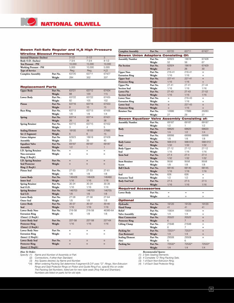
Bowen Fail-Safe Regular and H2S High Pressure
Wireline Blowout PreventersInternal Diameter (Inches) 2-1/2 2-1/2 3Body O.D. (Inches) 7-3/4 7-3/4 8-1/2Test Pressure - PSI 10,000 15,000 10,000Working Pressure - PSI 5,000 10,000 5,000Type of Service Reg. Reg. H2SComplete Assembly Part No. 63720 63711 67427
Weight 284 352 337
Replacement PartsUpper Body Part No. 63721 63712 67434
Weight 88 120 115Lower Body Part No. . 63722 63722 67435
Weight 82 105 102Piston Part No. 63716 63716 67433
Weight 8 10 15Race Ring Part No. 63713 63713 67430
Weight 1/8 1/8 1/4Spring Part No. 63714 63714 67431
Weight 26 26 38Spring Retainer Part No. 63715 63715 67432
Weight 3 4 5Sealing Element Part No. 18105 18105 37685Set (3 Segment) Weight 6 6 15Union Adaptor Part No. 62923 18618 67428Assembly Weight 25 35 45Equalizer Valve Part No. 69187 69187 69187Assembly Weight 1/2 1 1I.D. Spring Retainer Part No. ≡ ≡ ≡Non-extrusion Weight ≡ ≡ ≡Ring (2 Req’d.)I.D. Spring Retainer Part No. ≡ ≡ ≡Seal Protector Weight ≡ ≡ ≡Ring (2 Req’d.)Piston Seal Part No. 27-53 27-53 27-61
Weight 1/8 1/8 1/8Lower Body Part No. 146428 146428 146460Inner Seal Weight 1/16 1/16 1/16Spring Retainer Part No. 30-34 30-34 30-39Seal O.D. Weight 1/16 1/16 1/16Spring Retainer Part No. 146703 146703 146705Seal I.D. Weight 1/8 1/8 1/8Lower Body Part No. 27-58 27-58 27-64Outer Seal Weight 1/8 1/8 1/8Lower Body Part No. 30-37 30-37 30-40Seal Weight 1/16 1/16 1/16Lower Body Non- Part No. 216-58 216-58 46380-64Extrusion Ring Weight 1/8 1/8 1/8(Outer) (2 Req’d.)Lower Body Seal Part No. 227-58 227-58 227-64Protector Ring Weight 1/16 1/16 1/16(Outer) (2 Req’d.)Lower Body Non- Part No. ≡ ≡ ≡Extrusion Ring Weight ≡ ≡ ≡(Inner) (2 Req’d.)Lower Body Seal Part No. ≡ ≡ ≡Protector Ring Weight ≡ ≡ ≡(Inner) (2 Req’d.)
Complete Assembly Part No. 63720 63711 67427
Bowen Union Adaptors Consisting Of:Assembly Number Part No. 62923 18618 67428
Weight 52 56 67Pin Section Part No. 62924 18619 67429
Weight 24 26 30Upper Non- Part No. 216-41 216-41 ≡Extrusion Ring Weight 1/16 1/16 ≡Upper Seal Part No. 227-41 227-41 ≡Protector Ring Weight 1/16 1/16 ≡Upper Pin Part No. 27-41 27-41 27-44Section Seal Weight 1/16 1/16 1/16Lower Pin Part No. 27-43 27-43 27-52Section Seal Weight 1/16 1/16 1/16Lower Non- Part No. ≡ 216-43 ≡Extrusion Ring Weight ≡ 1/16 ≡Lower Seal Part No. . ≡ 227-43 ≡Protector Ring Weight ≡ 1/16 ≡Retainer Nut Part No. 12686 17888 20283
Weight 27 29 37
Bowen Equalizer Valve Assembly Consisting of:Assembly Number Part No. 69187 69187 69187
Weight 1/2 1 1/2Body Part No. 68620 68620 68620
Weight 1/4 1/2 1/4Stem Part No. 68998 68998 68998
Weight 1/8 1/8 1/8Body Lower Part No. 568-013 568-013 568-013Seal Weight 1/32 1/32 1/32Body Upper Part No. 27-12 27-12 27-12Seal Weight 1/16 1/16 1/16Stem Seal Part No. 27-4 27-4 27-4
Weight 1/32 1/32 1/32Stem Retainer Part No. 9558 9558 9558Screw Weight 1/8 1/8 1/8Ball Check Part No. 68145 68145 68145
Weight 1/16 1/16 1/16Seal Part No. 626 626 ≡Extractor Tool Weight 1/2 1/2 ≡Body End Seal Part No. 27-5 27-5 27-5
Weight 1/16 1/16 1/16
Required AccessoriesLower Body Part No. . ≡ ≡ ≡
Weight ≡ ≡ ≡OptionalHydraulic Part No. 19120 19120 19120Hand Pump Weight 41 41 41Relief Part No. 15834 15834 ≡Valve Assembly Weight 1/4 1/4 ≡Hose Connection Part No. 20522 20522 ≡Protector Ring Weight 6 7 ≡Lifting Clamp Part No. . 21648 21648 ≡
Weight 6 7 ≡Packing Set Part No. 72531* 72531* ≡(Gas Resistant) Weight 1/4 1/4 ≡Sealing Element Part No. 29508 29508 ≡(Set) Weight 6 6 . . . .Packing Set Part No. . 72532* 72532* 72533*
Weight 1/4 1/4 1/4
How To Order: Recommended Spares:Specify: (1) Name and Number of Assembly or Part. (1) 2 Sets Sealing Elements.
(2) Connections, if other than Standard. (2) 4 Complete ‘O’ Ring Packing Sets.(3) Any Spares desired, by Name and Number. (3) 1 of Each Non-Extrusion Ring.
*(4) When ordering Packing Set determine if segment B.O.P. uses “O” -Rings, Non-Extrusion (4) 1 of Each Seal Protector Ring.Rings and Seal Protector Rings on Piston and Guide Ring,If so, specify this on order.The Packing Set Numbers. listed are for new style seals (Poly Pak and Shamban).Numbers are listed on parts list for old style.
w w w . n a t o i l . c o m© Copyright 2003 National Oilwell
PDF/0903
MANUAL NO. 8551
w w w. c u s t o m e r. s e r v i c e @ n a t o i l . c o m
United StatesCorporate Office10000 Richmond AvenueHouston, TX 77042 USATel: 713-346-7500Fax: 713-346-7959
AlaskaP.O. Box 92962Anchorage, AK 99509 USA4111 IngraAnchorage, AK 99503-6117 USATel: 907-563-5253Fax: 907-561-0071
California4117 Atlas CourtBakersfield, CA 93308 USATel: 661-395-0165Fax: 661-328-1827
2875 Junipero AvnueSignal Hill, CA 90755 USATel: 562-988-0200Fax: 562-988-0350
Louisiana108 Nova DriveBroussard, LA 70518-4120 USAP.O. Box 446Broussard, LA 70518-0446 USATel: 337-839-2400Fax: 337-839-2211
190 Thompson RoadHouma, LA 70363 USATel: 504-851-1111Fax: 504-851-1117
Mississippi5349 Highway 11 North EllisvilleEllisville, MS 39437 USATel: 601-428-0646Fax: 601-428-0617
New MexicoBox 383Farmington, NM 87499 USA#14 CR 5860Farmington, NM 87401USATel: 505-326-4303Fax: 505-326-4304
North DakotaBox 731Williston, ND 58801 USA3202 1st Avenue WestWilliston, ND 58801 USATel: 701-774-0091Fax: 701-774-0092
Oklahoma3800 Thomas RoadOklahoma City, OK 73179 USAToll Free: 877-760-1711Tel: 405-677-2484Fax: 405-677-2457
Texas
Box 801Alice, TX 78333 USA1249 Commerce RoadAlice, TX 78332 USATel: 361-664-8013Fax: 361-664-0462
Manufacturing & EngineeringTexas8411 Irvington BoulevardHouston, TX 77022 USATel: 713-691-7800Fax: 713-691-7807
Box 18882810 Highway 135 NorthKilgore, TX 75662 USATel: 903-984-2553Fax: 903-984-7170
10720 West I-20 EastOdessa, TX 79765 USATel: 915-563-1173Fax: 915-563-1182
Box 159530444 Southwest FreewayRosenberg, TX 77471 USATel: 281-341-5365Fax: 281-344-1986
UtahBox 4821553 East Highway 40Vernal, UT 84078 USATel: 435-789-0670Fax: 435-789-6568
West VirginiaBox 927Route 2, Murphy Run RoadClarksburg, WV 26301 USATel: 304-622-4303Fax: 304-623-2174
Wyoming1283 N. Derrick DriveUnit 1, Box 2Casper, WY 82604-1887 USATel: 307-237-3100Fax: 307-237-2546
Canada9118 - 34A AvenueEdmonton, Alberta T6E 5P4CanadaTel: 780-702-5209Fax: 780-463-2348
DubaiP.O. Box 61490Round About No. 8Bldg. No. TA-06Jebel Ali, DubaiUnited Arab EmiratesTel: 971-4-833-8776Fax: 971-4-883-8795
GermanyEddesser Straße 131234 Edemissen BerkhöpenPostfach 31232GermanyTel: 49-5176-90326Fax: 49-5176-90532
IndonesiaCilandak Commercial EstateUnit 105Jl. Raya Cilandak KKOP.O. Box 7541Jakarta 12560, IndonesiaTel: 62-21-782-6088Fax: 62-21-782-6086
ScotlandKirkton AvenuePitmedden Road Industrial EstateDyce, Aberdeen AB21 0BFScotlandTel: 441-224-334800Fax: 441-224-723034
SingaporeUnit 1 Block 323Terrace WarehouseUntil Jan. 2003Loyang Offshore Supply BaseBox 5014Loyang Crescent,Singapore 508988Tel: 65-6542-5211Fax: 65-6542-8127
Drilling Solutions
Well Service and Completion Solutions
Downhole Solutions
Production Solutions
Supply Chain Management
Engineering and Project Management
Lifting and Handling Solutions