Embed Size (px)
Citation preview
Integrated Gate Driver Circuit Solutions
26 IGBT DRIVERS www.semikron.com
Issue 5 2010 Power Electronics Europe www.power-mag.com
Power electronics systems are commonly used in motor drive, power supply and power conversionapplications. They cover a wide output power spectrum: from several hundred watts in small drives up tomegawatts in wind-power installations or large drive systems. Inside the system the gate driver circuit withits extensive control and monitoring functions forms the interface between the microcontroller and thepower switches (IGBT). This article provides an overview of different gate driver topologies for differentpower ranges and shows examples for monolithic integration of the driver functionality. R. Herzer, J.Lehmann, M. Rossberg, B. Vogler, SEMIKRON Elektronik, Nuremberg, Germany
Today’s power conversion architecturesare based on pulse width modulation(PWM) to control the power, thefrequency and the voltage supplied fromthe mains to a given or unknown, fixed orvariable load [1]. Switches, controlled by adriver, repeatedly connect the load eitherto a supply voltage or to ground.Depending on the switching pattern, manyimplementations of the basic principle areemployed. For instance, current continuitycan be ensured either by turning theswitches on and off interchangeably or byswitching only one of them and using thefree-wheeling diode of the other.Generally, it will be possible to alter theshape of the current waveform passingthrough a load by varying the PWMhigh/low ratio [2].
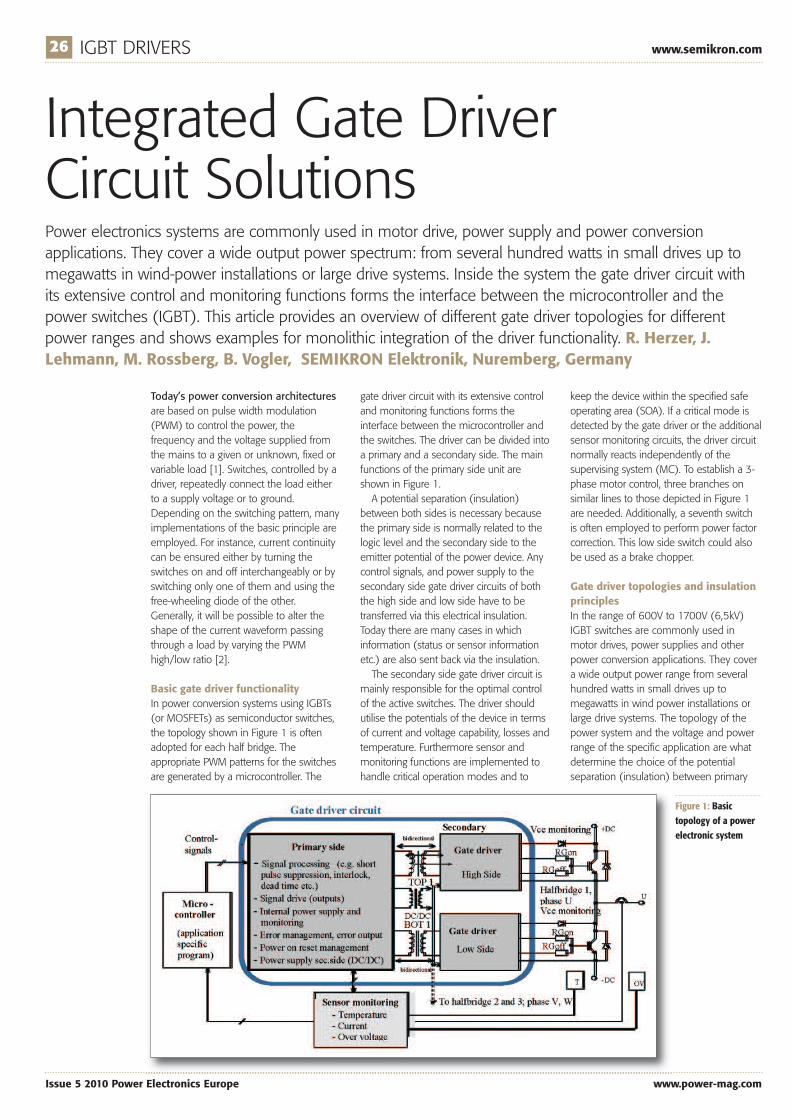
Basic gate driver functionalityIn power conversion systems using IGBTs(or MOSFETs) as semiconductor switches,the topology shown in Figure 1 is oftenadopted for each half bridge. Theappropriate PWM patterns for the switchesare generated by a microcontroller. The
gate driver circuit with its extensive controland monitoring functions forms theinterface between the microcontroller andthe switches. The driver can be divided intoa primary and a secondary side. The mainfunctions of the primary side unit areshown in Figure 1.A potential separation (insulation)
between both sides is necessary becausethe primary side is normally related to thelogic level and the secondary side to theemitter potential of the power device. Anycontrol signals, and power supply to thesecondary side gate driver circuits of boththe high side and low side have to betransferred via this electrical insulation.Today there are many cases in whichinformation (status or sensor informationetc.) are also sent back via the insulation.The secondary side gate driver circuit is
mainly responsible for the optimal controlof the active switches. The driver shouldutilise the potentials of the device in termsof current and voltage capability, losses andtemperature. Furthermore sensor andmonitoring functions are implemented tohandle critical operation modes and to
keep the device within the specified safeoperating area (SOA). If a critical mode isdetected by the gate driver or the additionalsensor monitoring circuits, the driver circuitnormally reacts independently of thesupervising system (MC). To establish a 3-phase motor control, three branches onsimilar lines to those depicted in Figure 1are needed. Additionally, a seventh switchis often employed to perform power factorcorrection. This low side switch could alsobe used as a brake chopper.
Gate driver topologies and insulationprinciplesIn the range of 600V to 1700V (6,5kV)IGBT switches are commonly used inmotor drives, power supplies and otherpower conversion applications. They covera wide output power range from severalhundred watts in small drives up tomegawatts in wind power installations orlarge drive systems. The topology of thepower system and the voltage and powerrange of the specific application are whatdetermine the choice of the potentialseparation (insulation) between primary
Figure 1: Basictopology of a powerelectronic system

www.semikron.com IGBT DRIVERS 27
www.power-mag.com Issue 5 2010 Power Electronics Europe
insulation, signal and energy transmissionin dependence on the application range. IGBT gate driver solutions and ICs for
high power applicationsFor some time now, effective system
integration solutions have existed in thelow power sector, [e.g.3-6]. In this mass-market environment, it is the ever-presentneed to cut costs which acts as the mainimpetus towards monolithic integration.State-of-the-art designs in the high powerrange, however, rely much less ondedicated ICs, because productionquantities are smaller and the variety ofproduct customisations, even for arelatively small number of units, is wider.Yet it is the conceptual difference betweenlow power and high power designs whichis actually most important. Only ICsspecially developed under high powercriteria [7 - 9] can adequately replaceexisting discrete solutions. But such ICs arenecessary to reduce the number ofdiscrete components at increasingfunctionality and lead to higher reliability,smaller volume and lower costs.
Primary and secondary side IGBTdriver ICs for pulse transformerA system structure particularly suited forcoping with high currents has already beenshown in Figure 1. The concept is centeredon physical potential separation by pulsetransformer (signals) and DC/DC converter(power supply) to divide the gate driverinto one primary (per system) and onesecondary side IC (per switch).The SIXPACK configuration suggests that
it is straightforward to merge all controlfunctionality into a single IC. A six-channelprimary side controller has thus beendesigned following the principle depictedin Figure 3.Three TOP and three BOTTOM input
signals come from the microcontroller. All
incoming signals are synchronised with theclock generated on-chip. They aresubjected to short pulse suppression andchecked for potentially hazardous patterns.An interlock time digitally adjustable by theuser is inserted between TOP andBOTTOM signals of each channel (TD1,TD2). Alternatively, a freely overlappingoperation can be programmed (SELECT).The three main digital cores perform mostof the functional signal processing. Severaldifferent modes of operation can beselected. A dedicated high powerconfiguration is activated by the GBSYNCsignal, allowing all three channels to beoperated synchronously. By this means,IGBT half-bridges are driven with minimalmutual delay, whether they are connectedin parallel for high output currents or inseries for high voltage operation. The resultis enhanced reliability and performance. The logic signals to be transmitted to
pulse transformers pass through levelshifters and are then amplified by CMOSoutput driver stages.Fault events such as supply voltage
monitoring being triggered, or error flagsbeing fed into the IC, are stored in an errormemory. Errors specific to each half-bridge(e.g. short circuit) are preprocessed in therelevant main core. Depending on theerror type, a characteristic pattern isgenerated by the error-coding unit.A chip photograph of an IC realised in
1�m CMOS technology is shown in Figure4. In the internal design, great emphasis hasbeen placed on fault-insensitive, ruggeddesign. As a part of the complex power-on-reset management, signal paths are safelyblocked with supply-independent structures.Six 1A drivers serve to transfer the outputpatterns onto pulse transformers. AdditionalDC/DC control circuitry and output stages(2x 1A) are present for the secondary sidepower supply.On the secondary side, single gate driver
ICs are utilised. The functional blockdiagram of the IC selected is given inFigure 5. Any incoming signal is recognised
and secondary side. On the other hand,the form of potential separation selectedhas a significant influence on the drivercircuitry, the reliability, noise immunity andthe costs of the driver. In a symmetrically grounded DC link
circuit (Figure 2a) for medium and highpower applications, external devices suchas optocouplers, transformers or fibreoptics are used for the galvanic insulationand the signal transfer. For anasymmetrically grounded DC link (Figure2b) and low power applications, it is inprinciple possible to realise the potentialseparation only for the high side switch(TOP). The easiest way is an integratedlevel-shifter (LS, no galvanic insulation). Inthis case the microcontroller, the primaryside, the emitter and secondary side gatedriver of the low side switch (BOT) have tobe on the same ground potential. Table 1summarises the different techniques for
Figure 2: Example of symmetric (a) andasymmetric (b) grounded DC link and differentpotential separation (PS)
Table 1: Gate drivertopologies, insulationand transmissionprinciples dependingon the power range

28 IGBT DRIVERS www.semikron.com
Issue 5 2010 Power Electronics Europe www.power-mag.com
by the input interface. Depending on thesystem configuration, the signal patternswill be differently transformed for internaluse. They are then fed into the centrallogic and error-processing unit. Finally, levelshifters send them to the main outputdrivers, which deliver up to 3A of peakcurrent to the IGBT gate. Thus, the IC isable directly to control IGBT modules up to300A. If higher system power is required,
external post amplifiers can be applied.It was essential to design the input
interface for high flexibility. Fig. 6 illustratestypical operating conditions at the input.Signal patterns transferred from theprimary side are either optically coupledsquare waves with the IGBT turn-offvoltage (DC-) as reference, or characteristicpulse transformer waveforms.While the normal input IN recognises
square waves, a pulse edge storage block(PES) connected to IN sets up the chip forpulse transformer environments. In thisconfiguration, pulses are reliably latched by
a feedback loop, ensuring high back swingimmunity. There is an additionalcomplication possible which will make itfeasible to drive negative turn-off voltagesat the output. For optimised turn-off lossesand noise immunity, it is desirable to drawthe IGBT gate potential below commonground. Internally, however, all circuits haveto refer to the lowest potential on-chip.The required level shifting also takes placeinside the input interface. As far as thenegative turn-off voltage is concerned,system designers can choose freelybetween 0V and -8V.The central logic is responsible for
filtering out all signal patterns that couldjeopardise the power semiconductorswitches. External and internal voltages aremonitored to identify threateningconditions. If the driver supply voltagewere not monitored, the IGBTs might beswitched on with too low gate voltage,thus leading to excessive power dissipationin the system. Likewise, any failure of theon-chip 5V supply requires to be handledto keep the system controllable.
The most common external faultsituation is IGBT current overloading. In thiscase, desaturation and strongly increasedcurrent will lead to a high VCE voltage dropacross the switch. Dynamic VCE detectiontherefore monitors the IGBT on-statevoltage with a customisable inhibit timeand VCE threshold.If an error is detected, the central logic
stores the error code and turns off theIGBT. An error signal is then transferredback to the primary side where the controlIC reacts, either generating a secondaryside reset or turning off the system globally.Errors are treated differently at power-on
of the IC. On ramping-up of the externalsupply voltages, a power-on-reset regimecontrols the chip initially. Redundantmechanisms prevent unintended switchingon of the drivers. No errors are reported tothe primary side during power-on-reset.Combining the concept of value-
independent level shifting with internalsupply and reference voltage generationallowed the IC to be realised with cost-effective 1�m, 12 mask, double metal,HV-CMOS technology. Figure 7 shows achip photograph of the manufactured IC.The high voltage transistors’ areaconsumption and SOA require thoroughoptimisation of the large 3A on-chip outputdriver stages. The IC has to be able to drivethe gates continuously and long-term at up
to 100kHz. The theoretical maximumfrequency was determined using 15Voutput swing and a load of 4.75� in serieswith 33nF capacitance. If power dissipationissues are disregarded, the peak current isnot internally limited by driver delay until>180kHz.
IGBT driver ICs with digital coreIn order to get a higher functionality andflexibility of IGBT driver for different
Figure 3: Primary side IC block diagram [10]
Figure 4: Chip photograph, primary sidecontroller (approx. 5.2mm x 4.3mm)
Figure 5: Secondary side IC block diagram [11]

30 IGBT DRIVERS www.semikron.com
Issue 5 2010 Power Electronics Europe www.power-mag.com
applications and/or to achievesophisticated and repetitive signaltransmission for all signals, includingsensing signals, a fully digital driver is themost favourable and universal solution inthe high power range [12]. Figure 8shows the block diagram of such a newand innovative concept with the mainfeatures of the primary and secondary
side control IC.The principle block structure is similar
to Figure 1 but the functionality of theprimary and secondary side control IC ismuch higher and more flexible(programmable). The insulation andsignal transmission between both sides isrealised in both directions by modems.The digital-based signal transmission usespulses with a defined length and shapegenerated by an internal digital logic. Thepulses are almost independent ofcomponent parameters and are, inadditional, evaluated differentially.Transmission reliability is achieved withhigh transformer currents and the farlower terminating impedance of thereceiver. As a result of this and also of therelative independence from componentparameters (modem), a high supplyvoltage for pulse generation is no longernecessary (3.3V is used).On the primary side a bidirectional data
transfer with the microcontroller isimplemented (3.3V or 5V interface).Input signals from �C are monitored forcritical frequencies. Short pulsesuppression, interlock and dead time etc.are user configurable. Further features arelisted in Figure 8. On the secondary side,the transferred signal is received by adifferential windows comparator andtransmitted to the digital logic for thesecondary-side encoding and signalprocessing. By modulating the repetitivelytransmitted pulses, communication forthand back between the primary andsecondary side can be achieved.Differentiated status or error signals, dataand furthermore sensor signals (e.g.temperature of IGBT module) can betransmitted continuously. Powerful 15V output stages are
implemented to drive the gates ofexternal post amplifiers (two MOSFET in apush-pull output configuration)separately, to avoid cross currents duringswitching. The output stage has twooutputs for easy asymmetric gate control.This allows for the gate resistor to be splitinto two resistors for turn-on and turn-off,respectively. The main advantage,however, is that this solution allows forseparate optimisation of turn-on and turn-off with regard to turn-on over-current,turn-off over-voltage spikes and short-circuit behaviour. Additionally, the digitallogic core can be used to drive andcontrol two output stages with differentparalleled gate resistors. This allows fortime dependency to be defined foreffective gate resistor switching of theIGBT and, thus, for the IGBT switching
Figure 6: Typical waveforms and potentials atthe interfaces
Figure 7: Chip photograph, secondary side IC(approx. 3.2mm x 2.6mm)
Figure 8: Blockdiagram and featuresof the digital driverconcept

www.semikron.com IGBT DRIVERS 31
www.power-mag.com Issue 5 2010 Power Electronics Europe
time sequences to be modulated. This inturn means reduced switching losses andstill allows for the over-voltage peak to belimited.Starting the development with FPGAs
on primary side and secondary side fordigital signal processing [12], thecomplete digital and analogous functionsof each side were integrated in a mixed-signal ASIC. Figure 9 shows the chip for
the primary side control IC. The mostimportant and visible circuit parts aremarked. The ICs are realised in a CMOStechnology which allows on the one handsynchronous design of the 3.3V digitalcore working at 40MHz and on the otherthe integration of powerful output stages(3.3V, 15V) and of circuit topologiessuitable for +15V/-15V operationvoltages. (To be continued in PEE6/2010).
Literature[1] B.Murari, F.Bertotti, G.A.Vignola:
Smart Power ICs: Technologies andApplications; Springer, Berlin,Heidelberg, New York, 1996[2] U.Nicolai, T.Reimann, J.Petzhold,
J. Lutz, P. Martin (Editor):SEMIKRON Application Manual;
ISLE, Ilmenau; 1998[3] K.Watabe, K.Shimizu, H.Akiyama,
T.Araki, J.Moritani,M.Fukunaga: A half-bridge driver IC
with newly designed highvoltage diode, Proc. ISPSD 2001, pp.
279-282
[4] International Rectifier; DataSheet IR 2135, IR 2235[5] A.Nakagawa: Single chip power
integration- High voltage SOI andlow voltage BCD, Proc. CIPS 2000,
pp. 8-15[6] S.Pawel, R.Herzer, M.Roßberg:
Fully integrated 600VDrive IC for medium power
applications operating up to 200°C,Proc. ISPSD 2005, pp. 55-58[7] M.Ramezani, C.A.T.Salama: A
monolithic IGBT gate driverimplemented in a conventional 0.8_mBiCMOS process, Proc. ISPSD 1998,pp. 109-112[8] R.Herzer, S.Pawel, J.Lehmann:
IGBT driver chipset for high powerapplications, Proc. ISPSD 2002, pp.
161-164[9] J.Thalheim: Chipset for flexible
and scalable high-performance gatedrivers for 1200V-6500V IGBTs, Proc.
ISPSD 2008, pp. 197-200[10] SEMIKRON; Data Sheet SKIC
6002[11] SEMIKRON; Data Sheet SKIC
1003, SKIC 1002[12] New PCIM 2008 Exhibits, Power
Electronics Europe, July/August 2008,pp. 16-21
Figure 9: Chip photograph of digital driverprimary side control IC (chip size 5.75mm x5.9mm; digital core 3.5mm x 4mm)
Name:
Company Name:
Address:
Post Code:
Tel: Total Number of Copies @ £ p+p Total £
Drives S & S Hyd H/B Pne H/B Ind Mot CompH/B H/B Air
DFA MEDIA LTD, Cape House, 60a Priory Road, Tonbridge, Kent TN9 2BL
QUANTITY QUANTITY
Hydraulics&Pneumatics There are now 6 of these handy
reference books from the publishers ofthe Drives & Controls and
Hydraulics & Pneumatics magazines.
Published in an easily readable styleand designed to help answer basicquestions and everyday problems
without the need to refer to weightytextbooks.
We believe you’ll find them invaluableitems to have within arms reach.
From the publishers of
QUANTITY QUANTITY QUANTITY
If you would like to obtain additional copies of the handbooks, please completethe form below and either fax it on 01732 360034 or post your order to:Engineers Handbook, DFA MEDIA LTD,Cape House, 60a Priory Road, Tonbridge, Kent TN9 2BLYou may also telephone your order on 01732 370340 Cheques should be made payable to DFA MEDIA LTD and crossed A/C Payee.Copies of the handbooks are available at £4.99 per copy.Discounts are available for multiple copies. 2-5 copies £4.30, 6-20 copies £4.10, 20+ copies £3.75.Postage and Packaging:1-3 copies £2.49 4 copies and over £3.49
QUANTITY
PRACTICAL ENGINEER’S HANDBOOKSPRACTICAL ENGINEER’S HANDBOOKS
HYDRAULICS
INDUSTRIALMOTORS
SERVOSAND STEPPERS
PNEUMATICS
COMPRESSED AIRINDUSTRIAL
ELECTRIC DRIVES
PLEASE ALLOW UPTO 28 DAYS FOR DELIVERY
H