Embed Size (px)
Citation preview

1Design Code, December 2016
L A N D A T
D E S I G N C O D E
D E C E M B E R 2 0 1 6
D E S I G N C O D EEagle Farm SouthA N D L A N D W E S T O F E A G L E F A R M S O U T H

All plans are reproduced from the Ordnance Survey Map with the permission of the Controller of HMSO. Crown copyright Reserved. Licence No. AR152684.
Barton Willmore The Blade, Abbey Square, Reading Berks RG1 3BE T: 0118 943 0000 F: 0118 943 0001 E: [email protected]
Desk Top Publishing and Graphic Design by Barton Willmore
This artwork was printed on paper using fibre sourced from sustainable plantation wood from suppliers who practice sustainable management of forests in line with strict international standards. Pulp used in its manufacture is also Elemental Chlorine Free (ECF).
Barton Willmore
Copyright
The contents of this document must not be copied or reproduced in whole or in part without the written consent of Barton Willmore.
J:\23000 - 23999\23800 - 23899\23850 - Strategic Land Allocation Design\A5 - Reports & Graphics\Graphic Design\Documents\Eagle Farm Design Code
Issue Date December 2016Job Number 23850Document Status FINALRevision oAuthor VariousChecked By TLAuthorised By TL
Contents
Introduction . . . . . . . . . . . . . . . . . . . . . . . . . . . . . . . . . . . . . . . . . . . . . . . . . . . . 31 .0 PURPOSE OF THE DESIGN CODE . . . . . . . . . . . . . . . . . . . . . . . . . . . . 4
2.0 THE ROLE OF THE MASTER DEVELOPER . . . . . . . . . . . . . . . . . . . . . . 6
3.0 USING THIS DOCUMENT . . . . . . . . . . . . . . . . . . . . . . . . . . . . . . . . . . . 7
Overarching Regulating Instructions . . . . . . . . . . . . . . . . . . . . . . . . . . . . 94.0 REGULATING PLANS AND STRATEGIES . . . . . . . . . . . . . . . . . . . . . . 10
Detailed Design Instructions . . . . . . . . . . . . . . . . . . . . . . . . . . . . . . . . . . . 155.0 CHARACTER AREAS . . . . . . . . . . . . . . . . . . . . . . . . . . . . . . . . . . . . . 16
6.0 STREET HIERARCHY . . . . . . . . . . . . . . . . . . . . . . . . . . . . . . . . . . . . . 28
7.0 KEY FRONTAGES . . . . . . . . . . . . . . . . . . . . . . . . . . . . . . . . . . . . . . . . 40
8.0 KEY SPACES . . . . . . . . . . . . . . . . . . . . . . . . . . . . . . . . . . . . . . . . . . . 48
Implementation & Delivery . . . . . . . . . . . . . . . . . . . . . . . . . . . . . . . . . . . . . 559.0 COMPLIANCE CRITERIA . . . . . . . . . . . . . . . . . . . . . . . . . . . . . . . . . . 56
10.0 IMPLEMENTATION AND REVIEW PROCESS . . . . . . . . . . . . . . . . . . 57
Appendix: Street Tree Plant List . . . . . . . . . . . . . . . . . . . . . . . . . . . . . . . . 58

3Design Code, December 2016
Introduction

Strategic Land Allocation, EFS4
1.0 PURPOSE OF THE DESIGN CODE
1.1 The purpose of this Design Code is threefold. It is designed to fulfil the objectives of the NPPF and PPG in helping to deliver high quality inclusive design without unnecessary prescription or detail, particularly relating to the design of individual buildings. The Code will therefore focus on instructing matters in relation to scale, density, massing, height, landscape, layout, access and materials.
1.2 It is also designed to meet the requirements of the Milton Keynes New Residential Development Design Guide, paragraph 5.3.3 of the Strategic Land Allocation Development Framework (SLADF) November 2013 and the guiding principles of the Eagle Farm South (EFS) Design and Access Statement (DAS) February 2014 and DAS Addendum June 2014, and Land West of Eagle Farm South (LWEFS) DAS December 2014 thereby ensuring
that the principles on which the strategic development site is based are not lost at the detailed design stage.
1.3 Lastly, this Code addresses Condition 23 of the planning permission for EFS requiring submission of a site wide design code for approval prior to the first application for reserved matters. It also addresses Condition 20 of the planning permission for LWEFS.
1.4 The Code does not seek to repeat plans and principles contained within the SLADF and Design and Access Statements but developers or designers looking to submit reserved matters applications for the sites should be familiar with the content of these documents to inform the proposed design approach.
The Decision Notice of 02.04.2015 for Eagle Farm South permits the:
‘Outline planning permission for mixed-use development for up to 410 dwellings, one primary school, mixed use local centre comprising of A1 retail and C3 residential uses, multi-functional green infrastructure including parkland, children’s play areas, informal open space, allotments, woodland, landscape and surface water attenuation, vehicular access point from the A421 via new roundabout junction, future connections to the adjoining development land to the west and east and internal streets, footpaths and cycleways’

5Design Code, December 2016
Figure 1.1 Strategic Land Allocation Illustrative Master Plan
EAGLE FARM SOUTHLAND WEST OF EAGLE FARM SOUTH
The Decision Notice of 02.04.2015 for Land West of Eagle Farm South permits the:
‘Outline planning permission for the development of up to 385 dwellings; multi-functional green infrastructure (totalling approx 2.58 ha) including parkland; children’s play areas, informal open space, allotments, woodland, landscaping and surface water attenuation; vehicular access via connections to adjoining development land to the west and east; internal street, footpaths and cycle ways’

Strategic Land Allocation, EFS6
The instructions contained within this Design Code are mandatory. This will ensure that there is clarity for both designers using the Code and the planning authority in assessing reserved matters applications against the content of this document.
It is recognised that over time the aspirations and requirements of all parties in the development process change, including as a result of a shifting policy context and market factors. Consequently, the Implementation and Review Process at the back of this document makes provision for periodic, formal review.
Outside of this formal review process it is recognised that there may be exceptional circumstances where localised deviation from the Code can create a better quality development and, in this context, early discussions with Officers will be required.
2.0 THE ROLE OF THE MASTER DEVELOPER
2.1 Gallagher Estates are one of the largest strategic land companies in the UK and play a unique role as ‘master developer’, taking forward and coordinating all aspects of the development process from site assembly, master planning and promotion through to the construction of access roads and drainage before delivering serviced land to the market place.
2.2 Post receipt of the Outline Planning Permission for the site, Gallagher Estates are continuing their master developer role by preparing information to discharge pre-commencement conditions of which this Design Code forms part.
2.3 The Design Code will be a key tool in ensuring a coherent and design quality approach across the site. It will be adopted by Milton Keynes Council, will form part of the tender packs for prospective house builders and help to coordinate the delivery process. Gallagher Estates view the Design Code as central to achieving its core values at EFS and LWEFS by providing the framework for high quality mixed use development to come forward.

7Design Code, December 2016
3.0 USING THIS DOCUMENT
3.1 This Code will be used as a reference document by the Local Authority, master developer (Gallagher Estates) individual developers and their design teams and will help ensure the coordinated design and delivery of EFS and LWEFS.
3.2 The Code has been carefully constructed as a concise and accessible document that is easy to use by those involved in working up and assessing reserved matters applications. The information contained within is specifically focused on providing instructions and a clear set of rules which are mandatory and avoids unspecific guidance, aspirational imagery or references which are ambiguous and can be interpreted in a variety of different ways.
3.3 The Code has been structured to reflect the way in which designers are likely to approach the design of individual parcels. As such, the Code is ordered in the following way: A series of overarching regulating instructions (Section 4) summarised in the Regulating Plans; and Detailed Design Instructions (Sections 5 – 8) relating to character areas, street hierarchy, key frontages, and key spaces; An individual developer and their design team should therefore use the Code in the following way:
• Start with the Overarching Regulating Instructions and use the Regulating Plans and Instructions (Section 4) to:
› Identify where within the sites the parcel of land subject to the reserved matters application is located;
› How this parcel of land relates to character areas, key streets, frontages, spaces and uses.
• Proceed to the Detailed Design Instructions and having been through 4 above, consider the following in order:
› Section 5 Character Areas: identify the design instructions relating to the relevant development parcel including land use, dwelling types, building line, landscape, materials and parking;
› Section 6 Street Hierarchy: identify the streets within and adjacent to the parcel and understand the design requirements of the public realm, building heights and boundary treatments;
› Section 7 Key Frontages: identify the key frontages within and adjacent to the parcel and understand the design requirements of each and how this fits into the wider context;
› Section 8 Key Spaces: identify any key spaces within and adjacent to the parcel and understand the design requirements of each and how this relates to the surrounding context.
Overarching Regulating Instructions3.4 The Regulating Instructions consist of a sequence of plans covering the entire site that provide the overarching spatial framework in which reserved matters applications for individual areas can be assessed to ensure a coherent and coordinated development. The Regulating Plans cover similar themes to those identified in the DAS but have evolved with the benefit of additional technical and design work appropriate to this stage. The Regulating Plans therefore provide a greater level of design certainty relevant to the preparation and assessment of reserved matters applications.

Strategic Land Allocation, EFS8

9Design Code, December 2016
Overarching Regulating Instructions

Strategic Land Allocation, EFS10
4.0 REGULATING PLANS AND STRATEGIES
4.1 The Regulating Plans are the overarching co-ordinating plans for the Code area. They have evolved from the parameters plans contained in the Design and Access Statement for Eagle Farm South and Land West of Eagle Farm South.
4.2 The Regulating Plans are the first point of reference for designers using the Code, providing the context in which individual parcels can be considered and ‘signposts’ the detailed design instructions that are relevant to each area set out in subsequent sections of this document. The Regulating Plans are shown in Figures 4.1 to 4.3.
Street Hierarchy Regulating Plan4.3 The Street Hierarchy Regulating Plan opposite sets out the primary pedestrian, cycle and vehicular movement corridors through EFS and LWEFS. The priority of walking and cycling modes is reflected in a comprehensive network of Redways that traverse the site adjacent to the A421, along the Spine Street and adjacent to Lower End Road. These Redways are linked north to south along the alignment of the Principal Spine Road and connect under the A421 to the employment land at Eagle Farm North.
Key Frontages/Spaces Regulating Plan4.4 The Key Frontages/ Spaces Regulating Plan identifies the four key frontages within EFS and LWEFS and, as the most visible parts of the site, are essential to establishing the design quality and place-making characteristics of the wider development. Adjacent to and contained within these key frontages are a series of key spaces that are equally important to the quality, character and legibility of the site and are subject to their own set of design instructions.
4.5 Underlying this information are the 3 character areas identified at the Outline stage. The principal way in which these character areas are differentiated is by the density strategy. The Formal Core will range from 50 - 30dph; the Suburban Core from 40 - 25dph; and the Rural Edge from 35 - 25dph. This reflects the progression from a more urban, built up area to the north adjacent to the A421, to a more rural environment to the south adjacent to Lower End Road. In discussions with Officers, and in the
interests of maintaining a distinct and cohesive neighbourhood identity in accordance with the New Residential Development Design Guide 2012, the design principles associated with key frontages, streets and spaces will take precedence over individual character areas.
Landscape Regulating Plan4.6 A Landscape Regulating Plan covering key spaces, hedge hierarchy and play spaces reflects the importance of integrating soft landscape and play in a co-ordinated way within the streets and development parcels. The following key planting criteria underpin the Landscape Regulating Plan:
• For each street typology only one species of hedge should be used to give them distinct character;
• Specimen shrubs should be used at key junctions, gateways and corners to aid in way finding and orientation;
• Landscaping areas should be provided to soften the street scene, avoiding blank walls, blank gable ends & blank fences;
• An updated Phase 1 habitat survey is required by Condition and its recommendations will be incorporated within the design of the development.
• Play area location and design should reflect the design guidance within both the Milton Keynes Play Area Action Plan 2013 and the Milton Keynes Local Plan 2001-2011;
• Play areas should include elements of inclusive play and for a range of ages;
• Play equipment should provide a range of equipment which develop different motor skills and encourage imaginative play;
• Play areas should include elements of natural play. The supplier of play equipment should be selected by consulting both with Milton Keynes Council and MKC’s nominated adopting body for parks and play areas (The Parks Trust).
Gateways4.7 Gateways occur at the intersection of key streets and spaces and the key ‘strategic’ gateways from the Principal Spine Road and Spine Street are shown on the Key Frontages/ Spaces Regulating Plan. Gateways are typically dynamic ‘go through ‘ spaces and signal the transition from one street or space to another. Gateways will comprise carefully articulated pieces of townscape. These may be defined by one or more of the following components:
• symmetrical or asymmetrical composition with buildings on both sides of the street;
• asymmetrical composition comprising buildings and landscape;
• include one or more ‘key buildings’ (see below) as part of the composition
4.8 The overall criteria is that they must provide a legible transition or clear threshold from one area to the next.
4.9 A myriad of incidental or ‘local’ gateways will occur throughout the code area. Incidental gateways will be distinct from strategic gateways by the use of more subtle and often asymmetrical townscape interventions.
Key Buildings4.10 Key buildings should be carefully considered as part of the overall street scene. Buildings above 2 storeys should perform a wider townscape function that contributes to place-making, such as through the enclosure of space, reinforcing the character of an area or providing a transition to focal spaces. Street elevations with taller buildings that cannot justify their townscape function are unlikely to be acceptable.
4.11 Key buildings should be designed so that they are distinct from the surrounding buildings by their scale, architectural style, detailing or materials or combination thereof.

11Design Code, December 2016
23850 - RG-M-AI E 06I
0 100 200
50 150 250m
N
Secondary Street
Side Street
Edge Street / Cul-De-Sac
Redway
Block Structure
Potential Bus Stop
Emergency Access
Spine Street
Leisure Route
Site Boundary
Principal Spine Road
Potential Principle Spine Road Extension
Secondary Street
Side Street
Edge Street / Cul-De-Sac
Redway
Block Structure
Potential Bus Stop
Figure 4.1 Street Hierarchy Regulating Plan
Note: The location of Side Streets and Mews Streets are not all shown on the Regulating Plan to allow fl exibility in the further subdivision of blocks at the reserved matters stage. Edge Streets can be linked or discontinuous streets subject to the detailed
design approach. Redway to Lower End Road will be delivered within site boundary.

Strategic Land Allocation, EFS12
23850 - RG-M-AI E 13L
0 100 200
50 150 250m
N
Gateway
School Site
Principal Spine RoadKey FrontageSite Boundary
Incidental Key Spaces
Key Space
Key View
Key BuildingAreas of Instruction for Key Spaces
Northern ParkKey Frontage
Formal Core
Suburban Core
Spine StreetKey Frontage
Lower End RoadKey Frontage
Rural Edge
Typically 2 - 3 Storey (Max. 13m)
Typically 2 - 2.5 (Max. 11.5m)
Up to 2 Storey with Occasional2.5 (Max. 11.5m)
FC01 FC02 FC03
FC04 FC05
FC07
SC01 SC02 SC03 SC04
SC05
FC06
FC09
FC10 FC11 FC12
FC13FC14
FC08
RE01 RE02 RE03
RE04
RE05
Lower End Road
Figure 4.2 Key Frontages/ Spaces and Character Areas Regulating Plan
Note: Maximum building heights specifi ed are to ridge.

13Design Code, December 2016
Figure 4.3 Landscape Key Spaces, Hedge Hierarchy and Playspace Regulating Plan 23850 - RG-M-AI E 34B
0 100 200
50 150 250m
N
Site Boundary
Local Area of Play
IDB Controlled Watercourse
Existing Trees Retained
Side Streets, Native Hedgerow(Singular Species)
Native Hedgerow
Secondary Roads, Native Hedgerow(Singular Species)
Existing Hedgerows Retained
Block Structure
Rural Edge
Neighbourhood Area of Play & Local Area of Play Development EdgeKey Spaces
Neighbourhood Play Areas
Local Play Areas
Note: All hedge planting shall be carried out with respect to highway visibility requirements. Species should be selected to avoid mature heights that obstruct visibility.

Strategic Land Allocation, EFS14

15Design Code, December 2016
Detailed Design Instructions

Strategic Land Allocation, EFS16
5.0 CHARACTER AREAS
FORMAL CORE
Vision and Development Concept5.1 The vision for the Formal Core character area is clear, and is designed to perpetuate the unique characteristics of Milton Keynes.
5.2 It recognises that the grid road structure, associated roundabouts and reserves as well as the City’s linear parks are the features that most strongly define the character of Milton Keynes. Within this structure, there has been great variation in layout and architectural appearance over time, but typically consistency within grid squares.
5.3 The Formal Core (and indeed the Suburban Core and Rural Edge character areas) will have a distinct, consistent and cohesive architectural language that will give development within the Strategic Land Allocation a unique identity from development within grid squares elsewhere within the City. Other key elements, such as strategic landscape, street materials and landscape and building materials will have a commonality that will promote the identity of the neighbourhood.
5.4 Within this framework, the Formal Core will have its own subtle, but distinct character stemming from a response to the attributes of the site and surrounding natural and built forms.
5.5 In particular, the character of the Formal Core will respond to the urban influences of: the adjacent A421 arterial route; upgrading works to dual carriageway; approved B8 storage and distribution uses to the north at Eagle Farm North; Principal Spine Road corridor that heads south through the site from the roundabout on the A421, and Spine Street that links the various parts of the SLA east to west through the centre of the site.
5.6 As such, the Formal Core will have: a higher average density (up to 50dph) than other parts of the Allocation; building heights (at up to 3 storeys) that frame key streets and spaces; a formality of layout to key streets and spaces; and a palette of materials that acknowledges the strong influence of more contemporary and industrial materials on land to the north.
5.7 Within this framework for the Formal Core character area, further instruction is provided in relation to 3 key frontages, including the Principal Spine Road, Northern Park and Spine Street.
WindowsWhere UPVC windows are specified, these should accord with the following criteria:
• The style and proportions of windows should reinforce the intended character of the building;
• A regular pane size should be selected for all windows within an elevation except where it is desirable to highlight a particular part of the elevation;
• Frames and glazing bars should be slender to ensure that they don’t dominate the window and create disproportionately small pane sizes;
• Applied glazing bars or glazing bars sandwiched between glass will not normally be acceptable.
DoorsDoors can make an important contribution to the character of an individual elevation, street, and identity of the wider character area. The specification of doors should accord with the following criteria:
• The style and proportions of doors should reinforce the intended character of the building;
• In formal areas and where there is a consistency of building typology a consistent door type and colour/finish should be used to perpetuate distinctiveness. Conversely, a different door style and/ or variation in door style and colour/ finish will be appropriate in less formal areas.

17Design Code, December 2016
Figure 5.1 Formal Core Location Plan 23850 - RG-M-AI E 29E
0 100 200
50 150 250m
N
Site Boundary
Formal Core
Lower End Road

Strategic Land Allocation, EFS18
Figure 5.2 External Building Materials Matrix
Development Parcel Land Use Density Building Heights Dwelling Types Key Buildings Street Type Building Line Space between
BuildingsFront Boundary Treatment*
External Materials Parking
FC01 - FC14
Residential
Parcel FC05 includes the Local Centre.
30 - 50dph
Development should range in height and include 2, 2.5 and 3 storey (max 13m to ridge).
See Section 7 Key Frontages for further specifi c design instruction).
Primary: Apartments,Terraces, Semi- detached
Secondary: Detached
Key buildings are shown on the Key Frontages and Spaces Regulating Plan (Figure 4.2). The characteristics will be consistent with the provisions of the Key Buildings instructions set out in Section 4.
Parcels FC04 - FC05 will also respect the Principal Spine Road Key Frontage Instructions in Section 7.
Parcels FC01, FC03, FC04, FC05, FC07, FC08 will also respect the Northern Park Key Frontage Instructions in Section 7.
Parcels FC01 - FC03, FC05, FC06, FC10 - FC14 will also respect the Spine Street Key Frontage instructions in Section 7.
The Street Hierarchy Regulating Plan (Figure 4.1) identifi es that the following typologies (excluding Side Streets and Mews Streets) are appropriate:
• Principal Spine Road
• Spine Street
• Secondary Street
• Edge Street
Section 6 Street Hierarchy identifi es the building line will be dictated by the following criteria:
Principal Spine Road: Variable.
Spine Street: Consistent set-back of between 1.5 - 6.0m.
Secondary Street: Consistent set-back of 2.0m. Up to 6m for front parking courts.
Edge Street: Varied set-back of 1.5 - 6.0m (including Lower End Road Key Frontage (Section 8).
Principal Spine Road: Typically consistent spacing between units (gable ends).
Spine Street: Gaps between units typically 1.0 - 3.0m but with occasional spacing of up to 7m.
Secondary Street: Varied gaps between units. Typically 3m or more.
Edge Street: Varied gaps between units. Typically 6m or more.
Principal Spine Road: Low hedge/shrub planting.
Spine Street: Vertical metal railings and hedge.
Secondary Street: Low brick walls (0.3m) with hedge planting immediately behind.
Edge Street: Low hedge/ shrub planting.
External Building Materials: See matrix below left.
Street Materials: See Street Hierarchy (Section 6).
In accordance with Parking Standards SPD (January 2016).
RO
OF
SLATE COMPOSITE
RED BRICK YELLOW BUFF BRICK
CONTEMPORARY CLADDING
STANDING SEAM METAL/ MEMBRANE
BLUE BRICK NEUTRAL RENDER
WA
LL
PRIMARY* SECONDARY
STANDING SEAM METAL
* Approximately 2/3rds of the composition.
Note: Contemporary window styles are appropriate for the Formal Core Character Area. Each building should have a consistent window style.
PLAIN TILE CLAY/ CONCRETE

19Design Code, December 2016
Table 5.1 Formal Core Design Principles Table
Development Parcel Land Use Density Building Heights Dwelling Types Key Buildings Street Type Building Line Space between
BuildingsFront Boundary Treatment*
External Materials Parking
FC01 - FC14
Residential
Parcel FC05 includes the Local Centre.
30 - 50dph
Development should range in height and include 2, 2.5 and 3 storey (max 13m to ridge).
See Section 7 Key Frontages for further specific design instruction).
Primary: Apartments,Terraces, Semi- detached
Secondary: Detached
Key buildings are shown on the Key Frontages and Spaces Regulating Plan (Figure 4.2). The characteristics will be consistent with the provisions of the Key Buildings instructions set out in Section 4.
Parcels FC04 - FC05 will also respect the Principal Spine Road Key Frontage Instructions in Section 7.
Parcels FC01, FC03, FC04, FC05, FC07, FC08 will also respect the Northern Park Key Frontage Instructions in Section 7.
Parcels FC01 - FC03, FC05, FC06, FC10 - FC14 will also respect the Spine Street Key Frontage instructions in Section 7.
The Street Hierarchy Regulating Plan (Figure 4.1) identifies that the following typologies (excluding Side Streets and Mews Streets) are appropriate:
• Principal Spine Road
• Spine Street
• Secondary Street
• Edge Street
Section 6 Street Hierarchy identifies the building line will be dictated by the following criteria:
Principal Spine Road: Variable.
Spine Street: Consistent set-back of between 1.5 - 6.0m.
Secondary Street: Consistent set-back of 2.0m. Up to 6m for front parking courts.
Edge Street: Varied set-back of 1.5 - 6.0m (including Lower End Road Key Frontage (Section 8).
Principal Spine Road: Typically consistent spacing between units (gable ends).
Spine Street: Gaps between units typically 1.0 - 3.0m but with occasional spacing of up to 7m.
Secondary Street: Varied gaps between units. Typically 3m or more.
Edge Street: Varied gaps between units. Typically 6m or more.
Principal Spine Road: Low hedge/shrub planting.
Spine Street: Vertical metal railings and hedge.
Secondary Street: Low brick walls (0.3m) with hedge planting immediately behind.
Edge Street: Low hedge/ shrub planting.
External Building Materials: See matrix below left.
Street Materials: See Street Hierarchy (Section 6).
In accordance with Parking Standards SPD (January 2016).
Materials5.8 The New Residential Design Guide recognises that Milton Keynes does not have a traditional local building material. It advises that a simplistic approach to materials should be taken, both in type of materials used and the extent of the palette.
5.9 Brick and render are strongly encouraged, with the ability to be used effectively in both contemporary and traditional designs. Other materials such as timber and cladding materials panels such as zinc, copper and lead are also encouraged in prominent locations such as key frontages and on landmark buildings.
5.10 To ensure a coherent elevation or street frontage, it recommends:
• the number of materials is restricted;
• the same materials are employed in the same parts of the facade or frontage;
• and no more than 3 facing materials should be used per elevation or street frontage.
5.11 The New Residential Design Guide also acknowledges that the choice of materials will be informed by the context.
5.12 In the instance of the Strategic Land Allocation, the immediate influences are the distribution buildings north of the A421 and Wavendon village to the south west.
5.13 The approach to choice and use of materials within the SLA is to identify a simple, primary palette of wall and roof materials that:
• will wear well and last a long time;
• can be used effectively in both contemporary and traditional designs;
• provide a common identity or unifying thread for the development.
5.14 Within this overarching context the Formal Core character area will have a palette of secondary materials, including contemporary materials, which can be used as accents to the primary material on individual buildings or provide variation between buildings within a frontage. This palette of secondary materials will reinforce the distinctiveness and legibility of the Formal Core without eroding the character and distinctiveness of the Allocation as a whole.
Note: *Boundary planting needs to respect highway visibility splays and any boundary planting should not exceed a mature height of 0.6m.

Strategic Land Allocation, EFS20
SUBURBAN CORE
Vision and Development Concept5.15 The Suburban Core character area provides the transition between the higher density, land to the north with a more urban character and the lower density, more rural land to the south. As a consequence the Suburban Core is characterised by mid range densities (up to 40dph) and heights (up to 2.5 storeys) and a greater diversity of materials, including a palette of more traditional secondary materials.
WindowsWhere UPVC windows are specified, these should accord with the following criteria:
• The style and proportions of windows should reinforce the intended character of the building;
• A regular pane size should be selected for all windows within an elevation except where it is desirable to highlight a particular part of the elevation;
• Frames and glazing bars should be slender to ensure that they don’t dominate the window and create disproportionately small pane sizes;
• Applied glazing bars or glazing bars sandwiched between glass will not normally be acceptable.
DoorsDoors can make an important contribution to the character of an individual elevation, street, and identity of the wider character area. The specification of doors should accord with the following criteria:
• The style and proportions of doors should reinforce the intended character of the building;
• In formal areas and where there is a consistency of building typology a consistent door type and colour/finish should be used to perpetuate distinctiveness. Conversely, a different door style and/ or variation in door style and colour/ finish will be appropriate in less formal areas.

21Design Code, December 2016
Figure 5.3 Suburban Core Location Plan 23850 - RG-M-AI E 30E
0 100 200
50 150 250m
N
Site Boundary
Suburban Core
Lower End Road

Strategic Land Allocation, EFS22
Figure 5.4 External Building Materials Matrix
Development Parcel Land Use Density Building Heights Dwelling Types Key Buildings Street Type Building Line Space between
BuildingsFront Boundary Treatment*
External Materials Parking
SC01 - SC05 Residential 25 - 40dphTypically 2 - 2.5 storeys (max 11.5m).
Primary: Mix of Detached, Semi- detached and terraced.
Secondary: Apartments.
Key buildings are shown on the Key Frontages and Spaces Regulating Plan (Figure 4.2). The characteristics will be consistent with the provisions of the Key Buildings instructions set out in Section 4
The Street Hierarchy Regulating Plan (Figure 4.1)identifies that the following typologies (excluding Side Streets and Mews Streets) are appropriate:
• Secondary Street
• Edge Street
Section 6 Street Hierarchy identifies the building line will be dictated by the following criteria:
Secondary Street: Consistent set-back of 2m. Up to 6m for front parking courts.
Edge Street: Varied set-back of 1.5-5.0m (including Lower End Road Key Frontage (Section 7).
Secondary Street: Varied gaps between units. Typically 3m or more.
Edge Street: Varied gaps between units. Typically 6m or more.
Secondary Street: Low brick walls (0.3m) with hedge planting immediately behind.
Edge Street: Low hedge/ shrub planting.
External Building Materials: See matrix below left.
Street Materials: See Street Hierarchy (Section 6).
In accordance with Parking Standards SPD (January 2016).
RO
OF
PLAIN TILE CLAY/ CONCRETE
BUFF BRICK RED BRICK STANDING SEAM METAL
STANDING SEAM METAL/ MEMBRANE
CONTEMPORARY CLADDING
NEUTRAL RENDER
WA
LL
PRIMARY* SECONDARY
FIBRE CEMENT WEATHERBOARD
* Approximately 2/3rds of the composition.
Note: Contemporary window styles are appropriate for the Suburban Core Character Area. Each building should have a consistent window style.
PLAIN TILE CLAY/ CONCRETE
SLATE COMPOSITE PANTILE CLAY/ CONCRETE

23Design Code, December 2016
Table 5.2 Suburban Core Design Principles Table
Development Parcel Land Use Density Building Heights Dwelling Types Key Buildings Street Type Building Line Space between
BuildingsFront Boundary Treatment*
External Materials Parking
SC01 - SC05 Residential 25 - 40dphTypically 2 - 2.5 storeys (max 11.5m).
Primary: Mix of Detached, Semi- detached and terraced.
Secondary: Apartments.
Key buildings are shown on the Key Frontages and Spaces Regulating Plan (Figure 4.2). The characteristics will be consistent with the provisions of the Key Buildings instructions set out in Section 4
The Street Hierarchy Regulating Plan (Figure 4.1)identifies that the following typologies (excluding Side Streets and Mews Streets) are appropriate:
• Secondary Street
• Edge Street
Section 6 Street Hierarchy identifies the building line will be dictated by the following criteria:
Secondary Street: Consistent set-back of 2m. Up to 6m for front parking courts.
Edge Street: Varied set-back of 1.5-5.0m (including Lower End Road Key Frontage (Section 7).
Secondary Street: Varied gaps between units. Typically 3m or more.
Edge Street: Varied gaps between units. Typically 6m or more.
Secondary Street: Low brick walls (0.3m) with hedge planting immediately behind.
Edge Street: Low hedge/ shrub planting.
External Building Materials: See matrix below left.
Street Materials: See Street Hierarchy (Section 6).
In accordance with Parking Standards SPD (January 2016).
Materials5.16 In accordance with the principle of promoting a common palette of building materials across the Allocation but with a transition of secondary materials from contemporary to traditional north to south the Suburban Core character area is the key part of the Allocation where this transition manifests itself.
5.17 The key distinction between the Formal Core and the Suburban Core character areas are:
• Brick remains the primary walling material but changes from red brick to buff brick;
• The primary roof material changes from slate composite to plain tile;
• A greater diversity of secondary materials is provided with fibre cement weatherboard and pantile featuring within the walling and roof palettes.
Note: *Boundary planting needs to respect highway visibility splays and any boundary planting should not exceed a mature height of 0.6m.

Strategic Land Allocation, EFS24
RURAL EDGE
Vision and Development Concept5.18 The Rural Edge character area will respond to its wider rural landscape context whilst still maintaining the common threads that unify the identity of the Allocation and differentiate it from other neighbourhoods within Milton Keynes.
5.19 The Rural Edge will be characterised by the lowest density development within the Allocation (up to 35dph), building heights that are restricted to a maximum of 2 storeys, and a more traditional palette of building materials.
5.20 In addition and consistent with the lower densities within this area, the building typologies will comprise a greater proportion of detached units.
WindowsWhere UPVC windows are specified, these should accord with the following criteria:
• The style and proportions of windows should reinforce the intended character of the building;
• A regular pane size should be selected for all windows within an elevation except where it is desirable to highlight a particular part of the elevation;
• Frames and glazing bars should be slender to ensure that they don’t dominate the window and create disproportionately small pane sizes;
• Applied glazing bars or glazing bars sandwiched between glass will not normally be acceptable.
DoorsDoors can make an important contribution to the character of an individual elevation, street, and identity of the wider character area. The specification of doors should accord with the following criteria:
• The style and proportions of doors should reinforce the intended character of the building;
• In formal areas and where there is a consistency of building typology a consistent door type and colour/finish should be used to perpetuate distinctiveness. Conversely, a different door style and/ or variation in door style and colour/ finish will be appropriate in less formal areas.
25Design Code, December 2016
Figure 5.5 Rural Edge Location Plan 23850 - RG-M-AI E 31D
0 100 200
50 150 250m
N
Site Boundary
Rural Edge
Lower End Road

Strategic Land Allocation, EFS26
Figure 5.6 External Building Materials Matrix
Development Parcel Land Use Density Building Heights Dwelling Types Key Buildings Street Type Building Line Space between
BuildingsFront Boundary Treatment*
External Materials Parking
RE01 - RE05 Residential 20 - 35dphUp to 2 storey with occasional 2.5 storey (max 11.5m)
Primary: Detached, Semi-detached
Secondary: Terraced
Key buildings are shown on the Key Frontages and Spaces Regulating Plan (Figure 4.1). The characteristics will be consistent with the provisions of the Key Buildings instructions set out in Section 4 and the Lower End Road Key Frontage instructions in Section 7.
The Street Hierarchy Regulating Plan (Figure 4.1) identifies that the following typologies (excluding Side Streets and Mews Streets) are appropriate:
• Edge Street
Section 6 Street Hierarchy identifies the building line will be dictated by the following criteria:
Edge Street: Varied set-back of 1.5 - 6.0m (including Lower End Road Key Frontage (Section 7).
Edge Street: Varied gaps between units. Typically 6m or more.
Edge Street: Low hedge/ shrub planting.
External Building Materials: See matrix below left.
Street Materials: See Street Hierarchy (Section 6).
In accordance with Parking Standards SPD (January 2016).
RO
OF
PLAIN TILE CLAY/ CONCRETE
BUFF BRICK RED BRICK
WA
LL
PRIMARY* SECONDARY
* Approximately 2/3rds of the composition.
Note: Traditional window styles are appropriate for the Rural Edge Character Area. Each building should have a consistent window style.
SLATE COMPOSITE PANTILE CLAY/ CONCRETE
NEUTRAL RENDER
FIBRE CEMENT WEATHERBOARD
HUNG TILES

27Design Code, December 2016
Table 5.3 Rural Edge Design Principles Table
Development Parcel Land Use Density Building Heights Dwelling Types Key Buildings Street Type Building Line Space between
BuildingsFront Boundary Treatment*
External Materials Parking
RE01 - RE05 Residential 20 - 35dphUp to 2 storey with occasional 2.5 storey (max 11.5m)
Primary: Detached, Semi-detached
Secondary: Terraced
Key buildings are shown on the Key Frontages and Spaces Regulating Plan (Figure 4.1). The characteristics will be consistent with the provisions of the Key Buildings instructions set out in Section 4 and the Lower End Road Key Frontage instructions in Section 7.
The Street Hierarchy Regulating Plan (Figure 4.1) identifies that the following typologies (excluding Side Streets and Mews Streets) are appropriate:
• Edge Street
Section 6 Street Hierarchy identifies the building line will be dictated by the following criteria:
Edge Street: Varied set-back of 1.5 - 6.0m (including Lower End Road Key Frontage (Section 7).
Edge Street: Varied gaps between units. Typically 6m or more.
Edge Street: Low hedge/ shrub planting.
External Building Materials: See matrix below left.
Street Materials: See Street Hierarchy (Section 6).
In accordance with Parking Standards SPD (January 2016).
Materials5.21 The Rural Edge character area will condense the palette of materials found within the Suburban Core to a more traditional palette of materials, reflecting the influence of the rural landscape and villages to the south.
5.22 The common palette of primary materials will remain a consistent thread within this area. However, the more contemporary materials from the secondary palette are discarded in favour of more traditional materials and includes hung tiles.
Note: *Boundary planting needs to respect highway visibility splays and any boundary planting should not exceed a mature height of 0.6m.

Strategic Land Allocation, EFS28
6.0 STREET HIERARCHY
PRINCIPAL SPINE ROAD
6.1 This infrastructure corridor is a strategic route and has been sized with the potential for it to become part of the wider Grid Road structure of Milton Keynes. However, to serve the SLA a 7.3 metre carriageway will be set within wide verges and connect with the new roundabout on the A421. This street will be lined with avenue trees on both sides of the carriageway and will have a combination of apartments and the gable ends of dwellings fronting onto this space.
Boundary Treatment 6.2 Low hedge/shrub planting will fill the curtilage from building face/ gable to boundary edge with the public realm.
Figure 6.1 Street Design Cross Section
(EQUIVALENT TO ‘LOCAL DISTRIBUTOR’ WITH LOCALISED VARIATION)
Bus Stop location, safe crossing points and techniques to restrict play opportunities within verge to be determined by detailed design
Verge may require appropriate measures to prevent or deter unauthorised access by vehicles such as through the use of a small
ditch and bank on the main carriageway side
Native hedge planting
Variable 5m 3m13.8m
7.3m
Tarmacadam Surface
Bulb planting mix to grass verge
Boulevard planting 12m centres
Grass verge
Extent of Principal Spine Road Corridor
29Design Code, December 2016
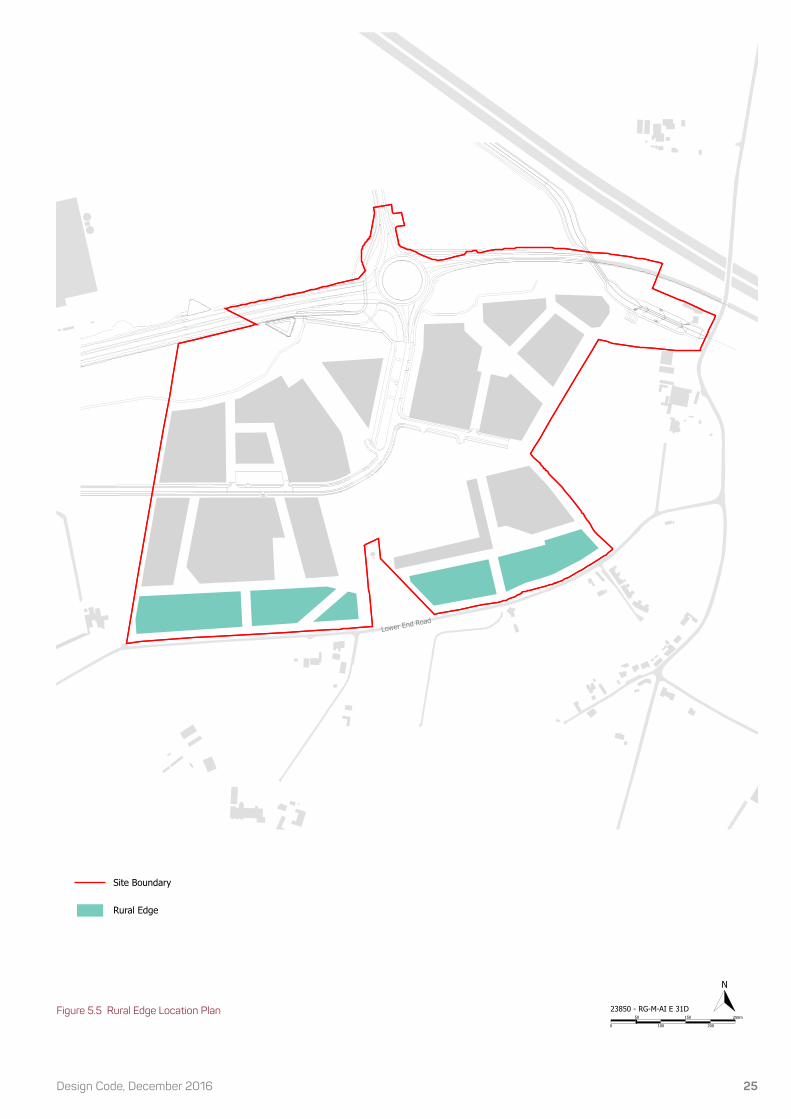
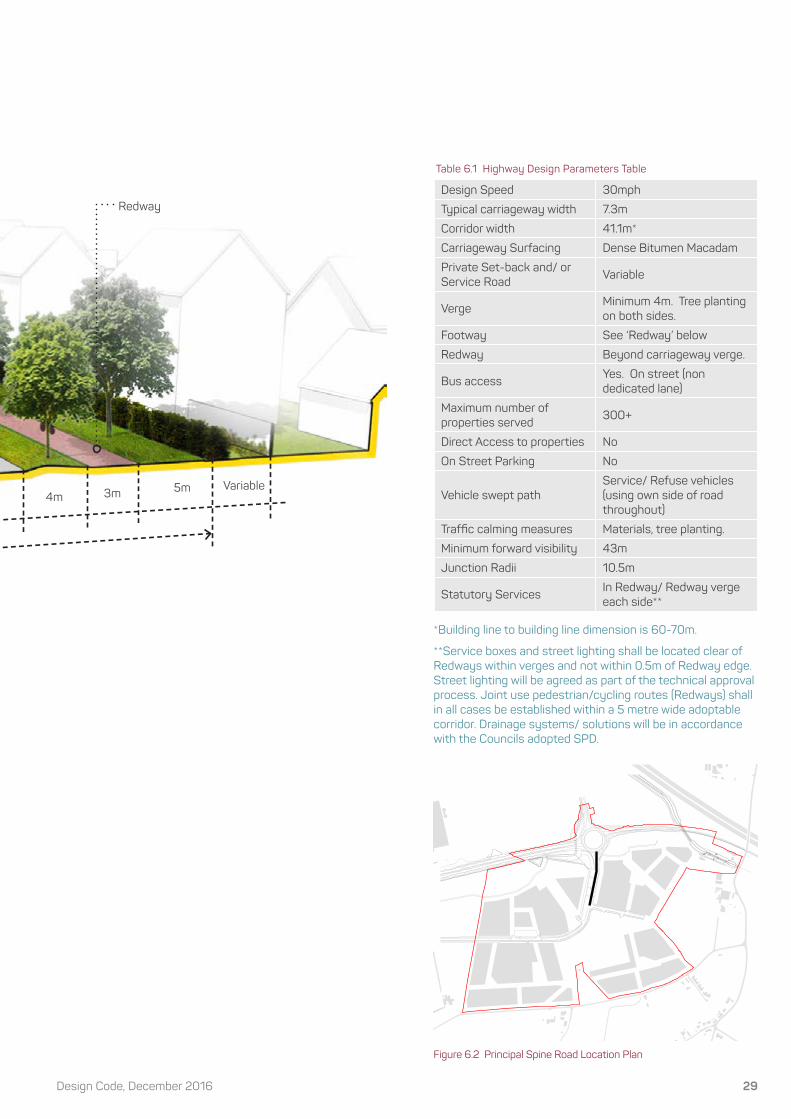
Figure 6.2 Principal Spine Road Location Plan
Table 6.1 Highway Design Parameters Table
*Building line to building line dimension is 60-70m.
**Service boxes and street lighting shall be located clear of Redways within verges and not within 0.5m of Redway edge. Street lighting will be agreed as part of the technical approval process. Joint use pedestrian/cycling routes (Redways) shall in all cases be established within a 5 metre wide adoptable corridor. Drainage systems/ solutions will be in accordance with the Councils adopted SPD.
Design Speed 30mph
Typical carriageway width 7.3m
Corridor width 41.1m*
Carriageway Surfacing Dense Bitumen Macadam
Private Set-back and/ or Service Road
Variable
VergeMinimum 4m. Tree planting on both sides.
Footway See ‘Redway’ below
Redway Beyond carriageway verge.
Bus accessYes. On street (non dedicated lane)
Maximum number of properties served
300+
Direct Access to properties No
On Street Parking No
Vehicle swept pathService/ Refuse vehicles (using own side of road throughout)
Traffic calming measures Materials, tree planting.
Minimum forward visibility 43m
Junction Radii 10.5m
Statutory ServicesIn Redway/ Redway verge each side**
3m4m5m
Redway
23850 - RG-M-AI E 14D
0 100 200
50 150 250m
N
Site Boundary
Principal Spine Road
Block Structure
Variable

Strategic Land Allocation, EFS30
SPINE STREET(EQUIVALENT TO ‘LOCAL DISTRIBUTOR’ WITH LOCALISED VARIATION)
6.3 The Spine Street is the principal east west movement corridor through the SLA and connects to the Principal Spine Road. The street will be lined by avenue trees to both sides and will also incorporate a Redway as an integral part of the street scene. Direct access to individual properties will be permitted where it retains the integrity of the avenue. Visitor parking will be accommodated within the verge and integrated with tree planting and street lighting to maintain the regular spacing of trees. The location and design of parking shall be co-ordinated across the street and between parcels to ensure a high quality street scene. Sporadic use of front courtyard parking areas serving a block of three to four terraced dwellings served by a single crossing of the redway for which highway approval would be
required.Building Heights6.4 Building heights along the Spine Street shall vary between 2 and 3 storeys. Further information on the configuration of building heights and the contribution they will make to the character of the Spine Street Key Frontage can be found in Section 8 of this Code.
Boundary Treatment 6.5 Vertical metal railings (approximately 0.9m high) and hedge planting will provide a unified boundary treatment to the Spine Street.
6.6 In front of the Mixed Use area, the boundary between the public and private space should be defined through a change in hard surfacing material.
Figure 6.3 Street Design Cross Section
Grass vergeTarmac Surfacing Redway
Boulevard 2m clear stem tree planting at approximately 12m centers
Metal railings or native formal clipped hedge planting to plot boundaries.
Precast Concrete Kerb
1.5- 6m2-3.5m
2m 2.5m3m 1m
6.75m

31Design Code, December 2016
Table 6.2 Highway Design Parameters Table
Figure 6.4 Spine Street Location Plan
*Excludes front gardens.
**Where verge accommodates parking next to a Redway, the verge must be a minimum of 3.5m (inclusive of 1m adoption strip for Redway).
*** Except where crossing of Redway is required.
****Vertical features can be integrated into the traffic calming approach. Street narrowing should be used in conjunction with vertical features.
Drainage systems/ solutions will be in accordance with the Councils adopted SPD.
All parallel visitor parking should be in spaces 6m long (with additional 1m x 1m entry and exit splays) and 2.5m wide. Where visitor parking is accommodated within the verge it shall be to the above dimensions with the 1m wide residual verge being constructed in a hard surface material to contrast with the surface finish used for the parking space and redway
Design Speed 30mph
Typical carriageway width 6.75m
Minimum/ Maximum corridor width* 15.75m - 18.75m
Carriageway Surfacing Dense Bitumen Macadam
Private Set-back 1.5 - 6.0m
Verge**2 - 3.5m with avenue tree planting/parking on both sides.
Footway Minimum 2m footway on one side.
Footway Surfacing Flexible macadam material or blockwork.
RedwayMinimum 3m cycleway on one side with 1m adoptable verges either side.
Bus access Yes. On street (non dedicated lane)
Maximum number of properties served 300+
Direct Access to properties*** Yes.
On Street ParkingYes. Parallel bays within verge on both sides
Vehicle swept pathRemovals/ Refuse vehicles (using own side of road at 20mph)
Traffic calming measures**** On street parking, materials, tree planting, building enclosure, road narrowing
Minimum forward visibility 43m
Junction Radii 10.5m
Statutory Services In footway/ Redway each side
Street Trees See Appendix
Metal railings and native hedge planting
1.5- 6m
23850 - RG-M-AI E 15D
0 100 200
50 150 250m
N
Site Boundary
Spine Street
Block Structure

Strategic Land Allocation, EFS32
SECONDARY STREET
Figure 6.5 Street Design Cross Section
The Secondary Street is designed to provide the access route to the residential areas north and south of the Main Spine Street. The Secondary Street will permit direct access to properties and be characterised by footways on either side of the street with verge/parking on one side. The Secondary Street will be distinct from Side Streets lower in the street hierarchy by virtue of the street width, materials and provision of footways.
Building Heights6.7 Building heights along Secondary Streets will typically be 2 storeys, with 2.5 storey buildings providing an opportunity to distinguish key buildings, spaces and aid wayfinding.
Boundary Treatment 6.8 Low brick walls walls (up to 0.3m high) with hedge planting immediately behind the wall line or low hedges will provide a transition from the higher level streets to lower level streets in the hierarchy.
Tarmac Surfacing Tarmac Surfacing with contrasting
blockwork at key junctions/ incidental spaces
Tree planting in planted verges
Precast Concrete Kerb
2-6m 2m2.5m
4.8 - 5.5m

33Design Code, December 2016
Table 6.3 Highway Design Parameters Table
* 4.8m based on 25-50 dwellings. 5.5m based on 50-100 dwellings. ** Excludes front gardens. *** One side of street only in any given cross section but will switch sides as part of traffic calming/ place making. Verge must be 2.5 metres wide where it accommodates parking. **** Vertical features can be integrated into the traffic calming approach. Street narrowing should be used in conjunction with vertical features.
Drainage systems/ solutions will be in accordance with the Councils adopted SPD.
All parallel visitor parking should be in spaces 6m long (with additional 1m x 1m entry and exit splays) and 2.5m wide.
Figure 6.6 Secondary Street Location Plan
Design Speed 20mph
Typical carriageway width* 4.8 - 5.5m
Minimum/ Maximum corridor width**
10.8 - 12m
Carriageway SurfacingDense Bitumen Macadam with contrasting sections of concrete block paving.
Private Set-back 2.0 - 6.0m
Verge*** 2.5m tree planting/parking
Footway2m footway on both sides. Cyclists in carriageway.
Redway No
Bus access No
Maximum number of properties served
50 - 100
Direct Access to properties Yes.
On Street Parking***Yes. Limited to parallel bays within verge
Vehicle swept pathRefuse vehicle passing car on street
Traffic calming measures****
On street parking, materials, building enclosure, road narrowing
Minimum forward visibility 25m
Junction Radii 6m
Statutory Services In footway each side
Street Trees See Appendix
Formal clipped hedges
2-6m2m
23850 - RG-M-AI E 16D
0 100 200
50 150 250m
N
Site Boundary
Secondary Street
Block Structure

Strategic Land Allocation, EFS34
SIDE STREET
6.9 Side Streets are shared surface streets that will accommodate a mixing of pedestrians and vehicles. Shared surface streets will integrate parking, vehicular movement, defensible space and place making considerations to create a low speed, high quality environment which encourages opportunities for social interaction. Side Streets have the opportunity to be designed as cul-de-sacs.
Figure 6.7 Street Design Cross Section
Concrete block paving
Formal clipped hedge boundary treatment
Feature tree to courtyard spaces
Small- medium sized tree to Side
Street
1-6m 0-5m 3.5-6m
5.5-13m overall
18 - 23m overall
Building Heights6.10 Side Streets shall be characterised by 2 storey buildings reflecting their subservient function to the higher order streets.
Boundary Treatment6.11 Low hedge/shrub planting will fill the curtilage from building face to boundary edge with the public realm to clearly demarcate the change between public and private space and protect residents privacy.
(EQUIVALENT TO ‘STREET’ WITH LOCALISED VARIATION)

35Design Code, December 2016
Table 6.4 Highway Design Parameters Table
* On one side of street only in any given cross section. Where the Side Street serves more than 25 units the footpath shall be defi ned by a kerb with an up-stand to create a clearly defi ned pedestrian space. **One side of street only in any given cross section but will switch sides as part of traffi c calming/ place making.
Drainage systems/ solutions will be in accordance with the Councils adopted SPD.
Design Speed 10-15mph
Typical carriageway width 3.5 - 6.0m
Minimum/ Maximum corridor width
5.5 - 13m
Carriageway Surfacing Block Paving
Private Set-back 1.0 - 6.0m
Verge No
Footway*2m footway within shared surface.
Redway No
Bus access No
Maximum number of properties served
Up to 50
Direct Access to properties Yes.
On Street Parking**Yes. 2.5m parallel parking or 5.0m perpendicular parking
Vehicle swept pathRefuse vehicle passing car on street
Traffi c calming measuresIntegral to design, including: on street parking, materials, building enclosure, road narrowing
Minimum forward visibility 25m
Junction Radii 6m
Statutory Services Within carriageway
Street Trees See Appendix
Concrete block paving Concrete block paving
(different colour to parking bays)
1-6m
Side Street
Informal Square
2m
Note: The location of Side Streets are not all shown on the Regulating Plan to allow fl exibility in the further
subdivision of blocks at the reserved matters stage. Figure 6.8 Side Street Location Plan
23850 - RG-M-AI E 18C
0 100 200
50 150 250m
N
Site Boundary
Side Street
Block Structure

Strategic Land Allocation, EFS36
EDGE STREET(EQUIVALENT TO ‘MINOR STREET’ WITH LOCALISED VARIATION)
Edge Streets are shared surface streets that are distinct by virtue of their relationship between development on one side and open space or landscape features on the other. Low levels of traffic movement allow carriageway widths to be kept to a minimum and the street to be subservient to the adjacent public and private landscape. Edge Streets have the opportunity to be designed as cul-de-sacs.
Building Heights6.12 Edge Streets will be defined by 2 storey buildings except where they from part of a Key Frontage (see separate instructions in Section 7 of this Code) and where a key buildings is required for townscape reasons.
Boundary Treatment 6.13 Low hedge/shrub planting will fill the curtilage from building face to boundary edge with the public realm to clearly demarcate the change between public and private space and protect residents privacy.
6.14 Side boundaries of corner units fronting the Edge Street shall typically comprise 1.8m high brick walls in line with the building face to provide privacy and security to private amenity areas. Low hedge/ shrub planting will fill the curtilage from building face and in front of the boundary wall to boundary edge with the public realm.
6.15 Boundary treatments as part of the dwelling curtilage shall comply with Secured by Design Standards and the provisions of the New Residential Development Design Guide.
Figure 6.9 Street Design Cross Section
Concrete block paving
Precast Concrete
Kerb
Low hedge/ shrub planting
3.2-4.1m1.5-6m 0-2.5m* 0.5m+
0.5m3.7-6.6m overall
Note: *Vehicles parked on plot in a perpendicular arrangement require a reversing depth of 6m from the back of the on-plot parking space.

37Design Code, December 2016
Design Speed 10mph
Typical carriageway width* 3.2 - 4.1m
Minimum/ Maximum corridor width
3.7 - 6.6m
Carriageway Surfacing Block Paving
Private Set-back 1.5 - 6.0m
Verge No
Footway No
Redway** No
Bus access No
Maximum number of properties served
Up to 25
Direct Access to properties Yes.
On Street ParkingYes. 2.5m parallel parking on open space side of street
Vehicle swept path Refuse vehicle
Traffic calming measures*** On street parking, materials, planting, road narrowing
Minimum forward visibility <10m
Junction Radii 6m
Statutory Services Within carriageway
Street Trees See Appendix
Table 6.5 Highway Design Parameters Table
*Localised widening to 6m will occur if perpendicular parking to the front of the building line is utilised. A width of 3.2m is only acceptable for short and distinct narrowings as a traffic calming feature. A width of 4.1m is acceptable for short straight horizontal alignments but may require localised widening to 6m where streets depart from this pattern.
**A Redway is incorporated as part of the Lower End Road Key Frontage. See separate coding instructions for this edge.
*** Vertical features can be integrated into the traffic calming approach. Street narrowing should be used in conjunction with vertical features.
Drainage systems/ solutions will be in accordance with the Councils adopted SPD.
Edge Streets should be designed in short lengths or be interrupted at regular intervals to provide access to streets of higher status in the chosen hierarchy. At all times they should be made uncomfortable for use over long distances through the application of a full suite of traffic calming measures.
Edge Streets should accommodate the need for refuse vehicles to turn.
Figure 6.10 Edge Street Location Plan******** Refer to Key Frontage (Lower End Road) for specific Coding information on these Edge Streets as appropriate.
Ditch/ Swale Tree planting (where not incompatible with maintenance easement)
variable
23850 - RG-M-AI E 19D
0 100 200
50 150 250m
N
Site Boundary
Edge Street
Block Structure

Strategic Land Allocation, EFS38
MEWS STREET(EQUIVALENT TO ‘SHARED STREET’ WITH LOCALISED VARIATION)
6.16 Mews will be shared by pedestrians, cyclists and vehicles and have an intimate character derived from the relationship of buildings and landscape to the shared surface space. Mews will occur where the subdivision of larger blocks are required. Mews Streets have the opportunity to be designed as cul-de-sacs.
Building Heights6.17 Building heights within Mews shall be a maximum of 2 storeys, reinforcing their subservient position within the street hierarchy and providing an appropriate enclosure of the street.
Boundary Treatment 6.18 A change in hard surfacing or ground cover shrub planting will demarcate the 1.5m private set-back within Mews.
Figure 6.11 Street Design Cross Section
Concrete block pavingPrecast concrete kerb laid flush to demarcated
pedestrian route
1.5m
5.3-11m overall
3.2 - 6.m carriageway

39Design Code, December 2016
Design Speed 10mph
Typical carriageway width 3.2 - 6.0m
Minimum/ Maximum corridor width
7.3 - 13.0m
Carriageway Surfacing Block Paving
Private Set-back 1.5m
Verge No
Footway No
Redway No
Bus access No
Maximum number of properties served
10
Direct Access to properties Yes.
On Street ParkingYes. Parallel, perpendicular or chevron parking
Vehicle swept path Refuse vehicle
Traffic calming measures On street parking, materials, planting, road narrowing
Minimum forward visibility 15m
Junction Radii 4m
Statutory Services Within carriageway
Street Trees See Appendix
Table 6.6 Highway Design Parameters Table
Shrub planting to form defensible frontage
1.5m0-5m

Strategic Land Allocation, EFS40
7.0 KEY FRONTAGES
PRINCIPAL SPINE ROAD
Principal Spine Road Frontage7.1 The Principal Spine Road Frontage will, for the majority of people, be the fi rst street that people experience within the Code area, connecting with the A421 and wider surroundings, particularly the employment allocations to the north. As such, the Principal Spine Road Frontage will need to serve a number of functions beyond those associated with its highways movement role. In the fi rst instance, the Frontage will need to provide a transition from the larger scale buildings built and consented to the north. Thereafter, it will need to contain and positively address the space allocated for this corridor and create a distinct, legible gateway into the site that sets the design approach for the remaining development within the Allocation.
7.2 The character of the Principal Spine Road Frontage is defi ned as:
• Being of a scale which responds to the primacy of the frontage through the site, comprising 2.5 and 3 storey dwellings;
• A distinct gable end to dwellings form between apartment ‘bookends’ which gives this frontage a unique character and legibility within the site;
• A predominantly apartment and detached typology with typically regular spacing between units;
• A common primary walling and roofing material which provides a consistent ‘thread’ through the street scene;
• Comprising avenue trees on both sides of the carriageway.
Building Type:
• Apartments;
• Semi-detached;
• Detached.
• Formal, deliberately composed buildings and compositions;
• Consistent spacing between units;
• Corner units to emphasise wayfinding/ placemaking function;
• Gable ends fronting Principal Spine Road between corner apartments.
• Consistent set-back within blocks.
• A consistent boundary treatment comprising low hedge and shrub planting will provide clear definition between the public and private realm.
Building Composition: Set-Back: Boundary Treatment:
Layout Principles Instructions

41Design Code, December 2016
Figure 7.1 Elevation Principles Instructions
The architectural approach to the Principal Spine Road frontage should be contemporary. As one of the most visible frontages (comprising apartments and the gable ends of dwellings) within the Strategic Land Allocation, this will help to perpetuate and reinforce the distinct and innovative architectural design response for which Milton Keynes is renowned.
Contemporary architectural approaches should:
Be of their time and place, refl ecting the City’s forward-looking ethos; avoid vernacular detailing/ ornamentation; add interest through recesses and projections; contribute to energy effi ciency requirements; embrace the opportunities provided by new materials / construction techniques.
MASSING
OVERARCHING CONCEPT
ROOF PROFILE
UNIT RHYTHM
Strategic Land Allocation, EFS42
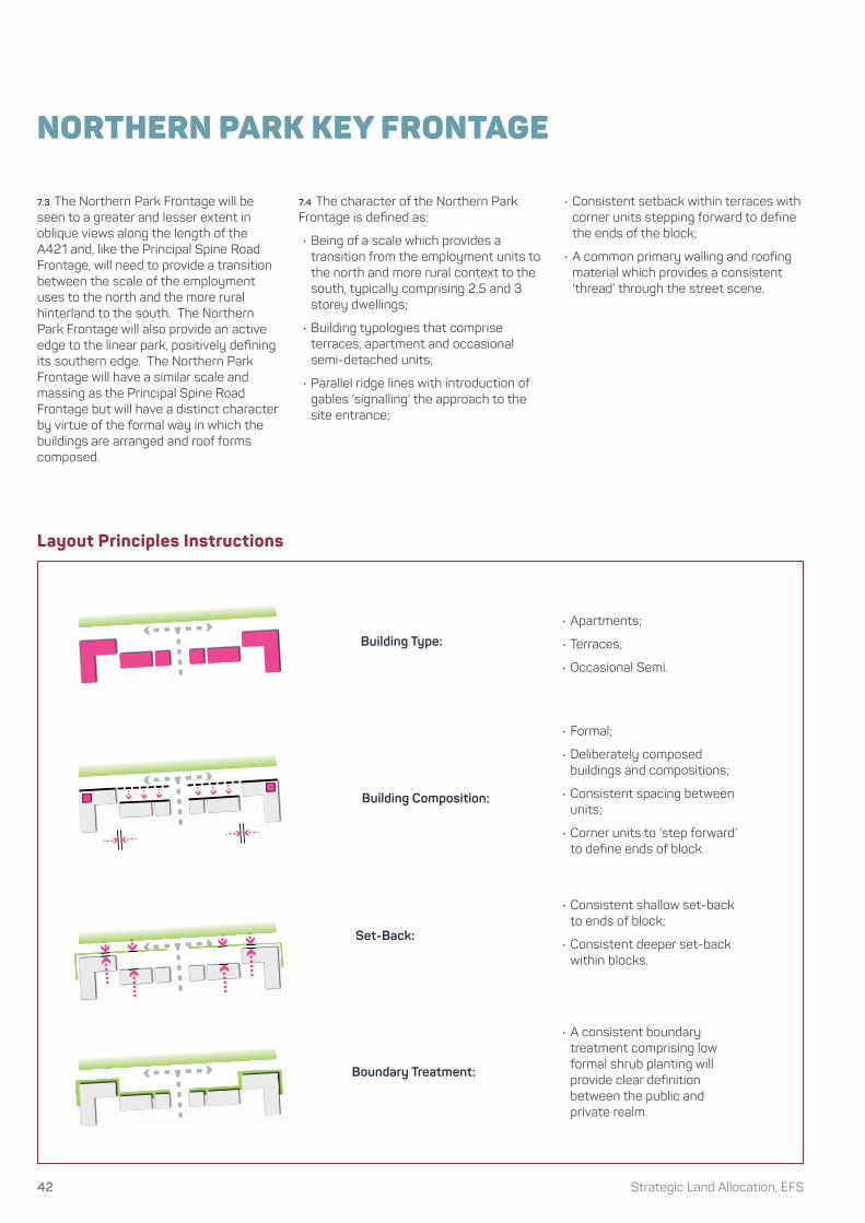
NORTHERN PARK KEY FRONTAGE
7.3 The Northern Park Frontage will be seen to a greater and lesser extent in oblique views along the length of the A421 and, like the Principal Spine Road Frontage, will need to provide a transition between the scale of the employment uses to the north and the more rural hinterland to the south. The Northern Park Frontage will also provide an active edge to the linear park, positively defi ning its southern edge. The Northern Park Frontage will have a similar scale and massing as the Principal Spine Road Frontage but will have a distinct character by virtue of the formal way in which the buildings are arranged and roof forms composed.
Building Type:
Building Composition:
Set-Back:
Boundary Treatment:
• Apartments;
• Terraces;
• Occasional Semi.
• Formal;
• Deliberately composed buildings and compositions;
• Consistent spacing between units;
• Corner units to ‘step forward’ to define ends of block.
• Consistent shallow set-back to ends of block;
• Consistent deeper set-back within blocks.
• A consistent boundary treatment comprising low formal shrub planting will provide clear definition between the public and private realm.
Layout Principles Instructions
7.4 The character of the Northern Park Frontage is defi ned as:
• Being of a scale which provides a transition from the employment units to the north and more rural context to the south, typically comprising 2.5 and 3 storey dwellings;
• Building typologies that comprise terraces, apartment and occasional semi-detached units;
• Parallel ridge lines with introduction of gables ‘signalling’ the approach to the site entrance;
• Consistent setback within terraces with corner units stepping forward to define the ends of the block;
• A common primary walling and roofing material which provides a consistent ‘thread’ through the street scene.

43Design Code, December 2016
Figure 7.2 Elevation Principles Instructions
MASSING
ROOF PROFILE
UNIT RHYTHM
OVERARCHING CONCEPT

Strategic Land Allocation, EFS44
SPINE STREET KEY FRONTAGE
7.5 The Spine Street is the principal east west movement corridor through the SLA and connects to the Principal Spine Road Frontage. Together with the Principal Spine Road Frontage, the Spine Street will be the primary way in which the majority of people navigate through and orientate themselves within the site. Befitting the Spine Streets function as a principal movement corridor, the massing will comprise a mixture of 2, 2.5 and 3 storey buildings (with a significant proportion of 2.5 and 3 storey buildings). In contrast
to the Principal Spine Road Frontage and Northern Park Frontage, the character will be less formalised with variation in building heights and ridge lines within terraces to create an organic appearance, inspired by the traditional high street.
7.6 The character of the Spine Street Frontage is defined as:
• Consistent shallow set-backs within blocks;
• A varied roof profile with variation in heights and ridge lines within terraces;
• A mixture of apartment, terraces and semi detached units;
• The street will be lined by avenue trees to both sides and will also incorporate a Redway as an integral part of the street scene;
• Sporadic use of front courtyard parking areas serving a block of three to four terraced dwellings served by a single crossing of the redway for which highway approval would be required.
Building Type:
Building Composition:
Set-Back:
Boundary Treatment:
• Apartments;
• Terraces;
• Semi-Detached;
• Detached;
• Mixed Use unit.
• ‘Informality’ through arrangement of varying building widths and heights;
• Deliberately composed buildings and compositions;
• Gaps between units kept to a minimum;
• Corner units to signal intersection with Secondary Streets.
• Consistent shallow set-back within blocks;
• A consistent boundary treatment defined by railings and hedge planting will provide clear definition between the public and private realm.
Layout Principles Instructions

45Design Code, December 2016
Figure 7.3 Elevation Principles Instructions
The architectural approach to the Spine Street frontage should be contemporary. As one of the most visible frontages within the Strategic Land Allocation, this will help to perpetuate and reinforce the distinct and innovative architectural design response for which Milton Keynes is renowned.
Contemporary architectural approaches should:
Be of their time and place, refl ecting the City’s forward-looking ethos; avoid vernacular detailing/ ornamentation; add interest through recesses and projections; contribute to energy effi ciency requirements; embrace the opportunities provided by new materials / construction techniques.
MASSING
ROOF PROFILE
UNIT RHYTHM
ANIMATING EDGES
OVERARCHING CONCEPT

Strategic Land Allocation, EFS46
RURAL EDGE - LOWER END ROAD AND NEWPORT ROAD SOUTH KEY FRONTAGE
7.7 The Lower End Road Frontage will have a unique rural character that refl ects the important role it has in providing a transition between the Allocation and the rural landscape to the south. Set behind the existing hedge line and a new Redway, development will be a recessive infl uence in views from Lower End Road, accentuated by a combination of restricted building heights (2 storey), variation in set-backs, low density, discontinuous frontages and new soft landscape.
7.8 The character of the Lower End Road Frontage is defi ned as:
• Varied set-backs in building lines between units within blocks;
• A variety of detached and semi-detached units;
• A consistent 2 storey building height with gable fronted pitched roofs to corner units addressing Lower End Road;
• A common primary walling and roofing material which provides a consistent ‘thread’ through the street scene;
• Soft landscape within curtilages and within the public realm will help soften this edge and make a significant contribution to the rural character.
Building Type:
Building Composition:
Set-Back:
Boundary Treatment:
• Detached;
• Semi detached.
• Informal;
• Deliberately composed buildings and compositions;
• Near discontinuous frontages;
• Corner units to signal intersection with Side Streets.
• Varied set-back in building lines between units within blocks.
• A 1.8m high brick wall will provide privacy to the private gardens of corner units where they face Lower End Road. The wall shall align with the face/ gable to the building;
• The private curtilage in front of the dwelling/ boundary wall shall be defined by soft landscape in the form of low hedges/ shrubs and or ground cover.
Layout Principles Instructions

47Design Code, December 2016
Figure 7.4 Elevation Principles Instructions
MASSING
ROOF PROFILE
UNIT RHYTHM
OVERARCHING CONCEPT
The Lower End Road Key Frontage will reference local character through the use of traditional materials (from the palette identified in Section 5) with an emphasis on brick, render, plain tile and pantile. It will also take its cue from local vernacular architecture by responding to the simple form, shallow plan, pitched roof typologies whilst providing continuity with the other character areas within this Code.

Strategic Land Allocation, EFS48
8.0 KEY SPACES
KEY SPACE - NORTHERN WETLAND PARK
8.1 The Northern Wetland Park will form part of a new gateway to Milton Keynes and to the SLA. As such, its importance goes beyond providing an attenuation function to accommodate the needs of the site and is a key space in its own right. The Park will be a dynamic, multifunctional linear green space that combines amenity, ecological and hydrological functions. Development will positively address and overlook the Park and accommodate a redway along its southern edge.
8.2 The redway will provide a common ‘thread’ through the site, linking other sites within the SLA through the linear park. It will provide connections northwards under the A421 to the employment areas at the junctions on the A421 and southwards through the Principal Spine Road corridor to link with the Spine Street.
8.3 Building heights on the southern edge of the Northern Park will provide positive defi nition of this space and facilitate a transition between the larger scale employment uses to the north and the predominantly residential SLA area to the south.
8.4 Attenuation features provide an exciting wetland park for informal amenity and a rich biodiverse habitat. A network of carefully positioned paths allow residents to undertake a variety of circular walks around the attenuation features connecting to the built development.
8.5 A series of timber decks traverse the wetland creating vistas and viewing platforms. Native woodland blocks enclose the space to the north and a strong formal avenue frames the southern boundary of the Northern Wetland Park softening the edge of the built form.
8.6 Wildfl ower and long grass planting surrounds the attenuation features generating a naturalistic environment. Marginal aquatic planting is incorporated into the wetland area and there are pools of standing water which enhance the overall natural characteristic of the park.
8.7 The design of the landscape must consider the practicalities of future maintenance of the landscape and the surface water management features. As such, the design of these areas must be prepared in consultation with the body that is nominated as taking on the long term maintenance of these areas.
8.8 The design of the Northern Wetland Park will include dialogue with the Canal & River Trust to respect the potential future canal alignment.
Figure 8.1 Indicative Northern Wetland Park Landscape Strategy Diagram
Figure 8.2 Northern Wetland Park Location Plan
Northern Park Landscape Strategy Diagram
Standing Water
Standing Water
Wild�owerGrassland
InformalFootpath
InformalFootpath
MarginalAquaticPlanting
MarginalAquaticPlanting
Native Woodland Planting
InformalPlayArea
Chunky Timber Deck
Chunky Timber Deck
Diverted water course
Linear Park
Strong Avenue Tree Line
Strong Avenue Tree LineLeisure route
A421
23850 - RG-M-AI E 20D
0 100 200
50 150 250m
N
Site Boundary
Northern Park
Block Structure
Key Landscape Spaces
School
Local shop
Local shop entrance plaza
Villgage square (School arrival
space)
Local equipped play space
Informal lawnNatural
amphitheatre
ArtSe
nsor
y ga
rden
Seating
Park squareFeature Tree
49Design Code, December 2016
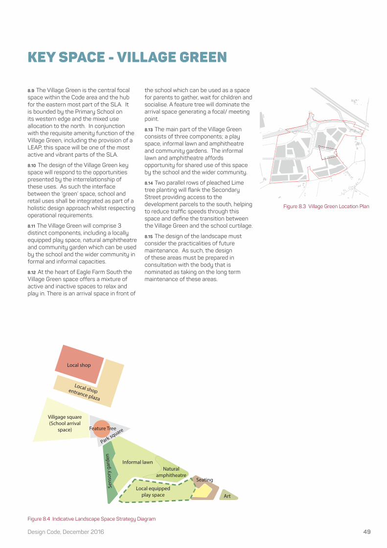
KEY SPACE - VILLAGE GREEN
8.9 The Village Green is the central focal space within the Code area and the hub for the eastern most part of the SLA. It is bounded by the Primary School on its western edge and the mixed use allocation to the north. In conjunction with the requisite amenity function of the Village Green, including the provision of a LEAP, this space will be one of the most active and vibrant parts of the SLA.
8.10 The design of the Village Green key space will respond to the opportunities presented by the interrelationship of these uses. As such the interface between the ‘green’ space, school and retail uses shall be integrated as part of a holistic design approach whilst respecting operational requirements.
8.11 The Village Green will comprise 3 distinct components, including a locally equipped play space, natural amphitheatre and community garden which can be used by the school and the wider community in formal and informal capacities.
8.12 At the heart of Eagle Farm South the Village Green space offers a mixture of active and inactive spaces to relax and play in. There is an arrival space in front of
the school which can be used as a space for parents to gather, wait for children and socialise. A feature tree will dominate the arrival space generating a focal/ meeting point.
8.13 The main part of the Village Green consists of three components; a play space, informal lawn and amphitheatre and community gardens. The informal lawn and amphitheatre affords opportunity for shared use of this space by the school and the wider community.
8.14 Two parallel rows of pleached Lime tree planting will fl ank the Secondary Street providing access to the development parcels to the south, helping to reduce traffi c speeds through this space and defi ne the transition between the Village Green and the school curtilage.
8.15 The design of the landscape must consider the practicalities of future maintenance. As such, the design of these areas must be prepared in consultation with the body that is nominated as taking on the long term maintenance of these areas.
Figure 8.3 Village Green Location Plan
Figure 8.4 Indicative Landscape Space Strategy Diagram
23850 - RG-M-AI E 21D
0 100 200
50 150 250m
N
Site Boundary
Village Green
Block Structure
Key Landscape Spaces
School
Local shop
Local shop entrance plaza
Villgage square (School arrival
space)
Local equipped play space
Informal lawnNatural
amphitheatre
Art
Sens
ory
gard
en
Seating
Park squareFeature Tree

Strategic Land Allocation, EFS50
KEY SPACE - SPINE STREET PARK
8.16 The Spine Street Park is a key focal space within LWEFS, providing an opportunity for a further local play area to complement the provision within the Village Green at EFS. The Park is bounded by an IDB controlled brook to the east and and the Spine Street to the north. At the intersection of the Principal Spine Road and the Spine Street, the Park will also have a high degree of visibility within the SLA.
8.17 The design of the Spine Street Park will positively respond to the opportunities afforded by its prominent location, key adjacencies and functional requirements to create a space that links strategic areas of open space and provides a transition to the rural landscape to the south.
8.18 At the heart of Spine Street Park is a play area with integrated natural play opportunities compartmentalised with shrub and specimen fruiting tree planting. The play are is broken up into areas for different ages, offering a range of play experience.
8.19 Formal lawns offer an open space opportunity and are framed by an avenue of trees and wildfl ower planting on the eastern boundary. Feature planting blocks bookend the north and south of the Park.
8.20 The design of the landscape must consider the practicalities of future maintenance. As such, the design of these areas must be prepared in consultation with the body that is nominated as taking on the long term maintenance of these areas.
Figure 8.5 Spine Street Park Location Plan Figure 8.6 Indicative Landscape Strategy Diagram
23850 - RG-M-AI E 22D
0 100 200
50 150 250m
N
Site Boundary
Principal Spine Road Park
Block Structure
Key Landscape Spaces
Gravel Area
Feature Planting
Feature Planting
NEAP
Existing Hedgerow
and Ditch
Informal lawn
Informal lawn
Informal lawn
Wild�ower Meadow Planting
Attenuation Feature
Edge Street
Attenuation Feature
Spine Road

51Design Code, December 2016
KEY SPACE - SPINE STREET SQUARE
8.21 The Spine Street Square is one of a series of spaces along the Spine Street that will punctuate the fl ow of movement across the SLA, aiding legibility and providing focal points for the surrounding community.
Figure 8.7 Indicative Landscape Strategy Diagram
Figure 8.8 Spine Street Square Location Plan
23850 - RG-M-AI E 23D
0 100 200
50 150 250m
N
Site Boundary
Spine Street Focal Space
Block Structure
Tree block planting
Gravel Area
Feature Planting
Spine Street planting
Informal lawn
Informal lawn
Block planting
Concrete block paving
8.22 The Square is the second of two key spaces within LWEFS, and will have a distinct character from the Spine Street Park. In part, this will be dictated by the smaller size of the space and enclosure by adjacent development on all sides. In conjunction with its central location within LWEFS, this dictates that it will have a more formal emphasis with a focus on quiet informal recreation.

Strategic Land Allocation, EFS52
INCIDENTAL KEY SPACES
8.23 The previous pages of this Code have provided a set of design instructions relating to the main ‘Key Spaces’ within the site. However, there will be a series of other lower tier or ‘Incidental Key Spaces’ throughout the site. Some of these are identified on the plan opposite but other incidental spaces may be appropriate where they contribute to place-making, way-finding and legibility functions.
8.24 In contrast to Key Spaces, which help shape and define the SLA at the macro level, Incidental Key Spaces will provide focal points for the immediate residential neighbourhood. Typically, Incidental Key Spaces won’t provide a formal function such as accommodating play provision to serve the wider area. However, they should be functional spaces, which could include accommodating incidental play opportunities for small children, opportunities for neighbours to gather, visitor parking etc.
8.25 Incidental Key Spaces should be designed to supplement the identity and legibility of the neighbourhood. In some instances, these spaces are on through routes. In other instances they represent the termination point of the higher order street network. In each case, the design approach should be responsive to the particular circumstances and may involve the truncation of views and vistas such that it feels like a destination space. In other instances, buildings will need to be arranged such that the onward route is ‘sign-posted’.
8.26 In all situations, the arrangement of building and landscape should be considered as part of an integrated design solution to create a well defined space with a strong sense of identity. Developers will be required to provide a high level of bespoke design for each incidental area of open space.

53Design Code, December 2016
Figure 8.9 Incidental Key Space Plan 23850 - RG-M-AI E 32C
0 100 200
50 150 250m
N
Site Boundary
Incidental Key Spaces

Strategic Land Allocation, EFS54

55Design Code, December 2016
Implementation & Delivery

Strategic Land Allocation, EFS56
9.0 COMPLIANCE CRITERIA
9.1 This section provides guidance to the designers of reserved matters applications and to Milton Keynes Council (the Planning Authority) in the determination of the applications. It sets out the key requirements of the Code in tabular form as a checklist, but it is not to be used as a substitute for the full relevant sections of the Code. Full compliance with the Design Code is expected, and a full supporting justification will be required for any deviation from it.
Process1. Designers of reserved matters applications should fully acquaint themselves with the provisions of the Code prior to starting design work.
2. Any arboricultural or habitat surveys should be reviewed due to the length of time since the previous surveys.
3. Designers should prepare a composite plan for their parcel that brings together all the spatial components of the Code, to inform the design of the parcel in three dimensions, taking account of any updated servicing or infrastructure information.
4. The designer should undertake pre-application negotiations with the Authority, submitting sketch proposals at least two weeks prior to any meeting so that the Authority can liaise with colleagues from other organisations if required (although the purpose of the Code is to avoid this, there may be exceptional circumstances, which the designer should flag up as non compliant proposals).
5. The Authority should examine the application not only against the Code but also against national and local policy, the relevant DAS.
6. The Authority will endeavour to process the application swiftly, making consultees aware of the provisions of the Code.
7. The application should be compliant with the Code and, if not it should be refused unless, if in the opinion of the Authority this is fully explained and justified and acceptable in all respects.

57Design Code, December 2016
10.0 IMPLEMENTATION AND REVIEW PROCESS
Implementation10.1 Design Codes are acknowledged as a powerful tool in delivering high quality development. The production of design codes in themselves, however, are only part of a process that needs to focus on quality in order to ensure the outcomes demanded by the NPPF. Central to delivering this quality is the extent to which the Code is understood and followed by designers working on reserved matters applications, and the extent to which the proposals are assessed against the content of the Code. Clearly, there is an important role for both the developer and the local authority in this process.
10.2 The role of the Design Code is not to be overly prescriptive and specify particular architectural solutions or detailing. As such there is no substitute for designers working up reserved matters applications to take inspiration from the policy and physical context to reinforce sense of place. Equally, the Local Planning Authority must be robust in their decision making process to ensure the high quality design all parties aspire to is delivered with EFS and LWEFS.
Monitoring and Review10.3 It is recognized that there is a need to monitor and review the Code as development proceeds on this site. It is recommended that an opportunity for formal review of the Code should take place every 3 years after the submission of the first reserved matters application. This provides for at least two formal reviews of the Code during the development and allows for lessons learned during the implementation of the Code during initial reserved matters applications to inform the preparation reserved matters for subsequent phases.
10.4 Outside of the formal review mechanism, there may be circumstances where a designer, working up proposals in accordance with the Code, feels that a building or group of buildings could better contribute to the quality and identity of the development by localised deviation from the Code. In these circumstances a strong rationale and justification for the approach being proposed is recommended in conjunction with early discussions with Milton Keynes Council. Exemptions from the Code will only be allowed in exceptional circumstances.

Strategic Land Allocation, EFS58
Appendix:Street Tree Plant List

59Design Code, December 2016
SPINE STREET TREES: typically 25-30cm girth, Minimum 2.1m clear stemQuercus Palustris 25-30 450-500 Air pot Semi-mature Clear stem to 2.1m 10-15mCastanea sativa 25-30 450-500 Air pot Semi-mature Crown spread 175-250cmFagus sylvatica 25-30 450-500 Air pot Semi-mature Clear stem to 2.1m 10-15mTilia x euchlora 25-30 450-500 Air pot Semi-mature Crown spread 175-250cmTilia X europaea 25-30 450-500 Air pot Semi-mature Crown spread 175-250cmPlatanus hispanica 25-30 450-500 Air pot Semi-mature Crown spread 175-250cm
SECONDARY STREET TREES typically 18-20cm girth Minimum 2.1m clear stemAcer campestre Elsrijk 18-20 400-450 Air pot Clear stem to 2.1m 10-15mAlnus incana ‘Laciniata’ 18-20 400-450 Air pot Clear stem to 2.1m 10-15mGleditsia triacanthos f. inermis ‘Sunburst’16-18 400-450 Air pot Clear stem to 2.1m 10-15mLiriodendron tulipifera ‘Fastigiatum’ 16-18 Air pot Semi-mature, Clear stem to 2.1m 10-15mMalus Tschonoskii 16-18 400-450 Air pot Clear stem to 2.1m 10-15mPrunus Hillieri Spire 18-20 400-450 Air pot Clear stem to 2.1m 10-15mSorbus Sheerwater Seeding 18-20 400-450 Air pot Clear stem to 2.1m 10-15m
SIDE STREET TREES typically 16-18cm girth Minimum 2.1m clear stemAcer platanoides Columnare 16-18 450-500 Air pot Semi-mature, Clear stem to 2.1m 10-15mBetula utilis jacquemontii 16-18 400-450 Air potCarpinus Betulus Fastigiata 16-18 450-500 Air pot Semi-mature 10-15mFagus sylvatica ‘Dawyck’ 16-18 450-500 Air pot Semi-mature Crown spread 175-250cmGleditsia triacanthos f. inermis ‘Sunburst’16-18 400-450 Air pot Clear stem to 2.1m 10-15mLiriodendron tulipifera ‘Fastigiatum’ 16-18 Air pot Semi-mature, Clear stem to 2.1m 10-15mPrunus ‘Sunset Boulevard 16-18 400-450 Air pot Clear stem to 2.1m 10-15mSorbus aucuparia ‘Sheerwater seedling’ 16-18 450-500 Air pot Semi-mature Crown spread 175-250cm
EDGE STREET TREES typically 18-20cm girth Minimum 2.1m clear stemCorylus avellana 8-10 300-350 Air pot Multistem min. 8 breaks, bushyCrataegus monogyna ‘Stricta’ 18-20 400-450 Air pot Clear stem to 2.1m 10-15mCastanea sativa 18-20 450-500 Air pot Semi-mature Crown spread 175-250cmFraxinus excelcior 18-20 450-500 Air pot Semi-mature Crown spread 175-250cmPicea omorika 350-400 Air pot Semi-mature Crown spread 175-250cmPrunus avium 18-20 450-500 Air pot Semi-mature Crown spread 175-250cmPrunus padus 18-20 450-500 Air pot Semi-mature Crown spread 175-250cmBetula pendula 18-20 450-500 Air pot Semi-mature Crown spread 175-250cmQuercus robur 18-20 450-500 Air pot Semi-mature Crown spread 175-250cm
MEWS TREES – restricted space Typically 14-16cm girth Minimum 2.1m clear stemAmelanchier lamarkii 16-18 300-350 Air pot Multistem min. 8 breaks, bushyBetula utilis jacquemontii 16-18 400-450 Air potCarpinus Betulus Fastigiata 16-18 450-500 Air pot Semi-mature 10-15mGleditsia triacanthos f. inermis ‘Sunburst’16-18 400-450 Air pot Clear stem to 2.1m 10-15mLiriodendron tulipifera ‘Fastigiatum’ 16-18 Air pot Semi-mature, Clear stem to 2.1m 10-15mPrunus ‘Amonogawa’ 14-16 300-400 Air pot FeatheredPrunus serrula ‘Tibetica 14-16 300-400 Air pot FeatheredSorbus aucuparia ‘Sheerwater seedling’ 16-18 450-500 Air pot Semi-mature Crown spread 175-250cm

Strategic Land Allocation, EFS60