Embed Size (px)
Citation preview

2.3Construction on Site (WAC 463-42-145)
WAC 463-42-145 PROPOSAL — CONSTRUCTION ON SITE.The applicant shall describe the characteristics of the construction to occur at the proposed site
including the type, size, and cost of the facility; description of major componentsand such information as will acquaint the council with the significant features of the proposed project.
[Statutory Authority: RCW 80.50.040(1) and chapter 80.50 RCW.81-21-006 (Order 81-5), §463-42-145, filed 10/8/81. Formerly WAC 463-42-210.]

Satsop CT Project Phase II 2.3-1 November 2001SCA Amendment #4
K:\020\Duke Energy\Phase 2\Revised Application\Section 2.3.doc
2.3 CONSTRUCTION ON SITE(WAC 463-42-145)
This section provides information on the proposed project and construction of the project in thefollowing sections:
� Project Summary (Section 2.3.1)� Power Plant Description (Section 2.3.2)� Power Plant Construction (Section 2.3.3)
2.3.1 PROJECT SUMMARY
Duke Energy Grays Harbor, LLC, and Energy Northwest (the Certificate Holder) is proposing toexpand the Satsop Combustion Turbine (CT) Project by 600 megawatts (MW), doubling thegenerating capacity of the project. Like Phase I, Phase II will consist of two combustion turbinegenerators and a single steam turbine generator. Certain facilities installed for Phase I, such as theoperations and control office, warehouse, workshops and stores, gas regulation and treatment, andthe water treatment building are adequately sized to serve both Phase I and Phase II, and newfacilities of this type are not required.
A combined cycle plant uses exhaust gases from the combustion turbine that might otherwise beexhausted into the atmosphere without recapturing any of the heat content. In the proposed project,natural gas and air will be mixed and ignited in a combustion turbine. The combustion turbinesproduce about one-half of the plant’s electrical output, and emit hot gases as a byproduct. The hotgases exhausted by the combustion turbines will be used to produce steam in a heat recovery steamgenerator (HRSG). The high-energy steam from the HRSG will be piped into a steam turbine thatgenerates the remaining one-half of the unit's electrical output.
The total estimated value of Phase II at the completion of the construction is approximately $400million for construction of the plant. The Certificate Holder estimates that the annual operating andmaintenance costs will be approximately $12 million, including the following:
� Wages and salaries of operation, maintenance, and administrative personnel� Procurement of goods and services� Insurance� Sales, property and other state and local taxes
Figures 2.3-1 and 2.3-2 present conceptual isometric diagrams of the proposed project (Phase I andPhases I and II, respectively). Figure 2.3-3 is a plant configuration diagram for Phase II, showingthe major component systems for the plant. Figure 2.3-3 shows the major facilities/systems thatwill support the turbine trains, including the steam condensing/cooling system and the electricalinterconnection system.

Satsop CT Project Phase II 2.3-2 November 2001SCA Amendment #4
K:\020\Duke Energy\Phase 2\Revised Application\Section 2.3.doc
Process water will be purchased from the Grays Harbor Public Development Authority andsupplied from the existing Ranney collectors via the existing Satsop Development Park watersupply line that services Phase I facilities. This water is transported to Phase II through an existingwater pipeline that passes adjacent to the site (see Figure 2.3-4). The existing outfall structure tothe Chehalis River will be used for discharge of the Satsop CT Project's process effluent.
Potable water will be obtained from the existing Satsop Development Park raw water well. Thissystem includes a supply tank and pump house located contiguous to the northeast corner of the siteand will provide high-quality water that will be treated as necessary for potable uses. Sanitarywastewater will be discharged through an on-site septic system and leach field constructed for theplant.
Fuel for Phase II will be provided by the natural gas pipeline constructed as part of Phase I.
Power produced by Phase II will be routed through transmission lines that will connect to the BPAsystem at the Satsop substation. The lines will be constructed by BPA as part of Phase I.
2.3.2 POWER PLANT DESCRIPTION
2.3.2.1 Overview
The Certificate Holder is proposing to construct and operate Phase II to help supply growingregional electrical loads. This plant will be a combined cycle power plant with a nominalaverage output of 600 MW to be constructed on the site already certified for Phase I.
Like Phase I, Phase II will use the General Electric (GE) Frame 7FA combustion turbines in a 2-x-1combined cycle configuration with a GE D11 steam turbine. Each GE 7FA combustion turbinegenerates a nominal gross power output of 175 MW, while the steam turbine generatesapproximately 300 MW gross with inlet chilling and maximum duct firing at annual averagetemperature. Phase II also features GE 7H2 hydrogen-cooled generators for the combustionturbine and stream turbine.
A basic description of Phase II is presented in Section 2.3.2.2. Detailed power plant design andspecification information was provided as Appendix B to the original SCA application; as aconvenience to the reader, that appendix is reproduced here as Appendix A to this amendment. Adetailed description of the cooling systems is provided in Section 2.6 - System of Heat Dissipation,WAC 463-42-175. The basic building structures can be found on Figures 2.3-2, 2.3-3, and 2.3-4. Plant elevations are illustrated in Figure 2.3-5. The approximate heights of the major plantcomponents are listed in Table 2.3-1.
Satsop CT Project Phase II 2.3-3 November 2001SCA Amendment #4
K:\020\Duke Energy\Phase 2\Revised Application\Section 2.3.doc
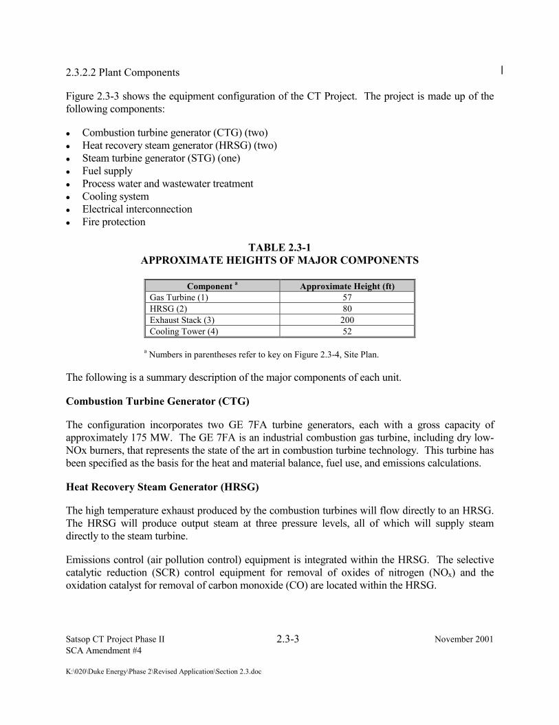
2.3.2.2 Plant Components
Figure 2.3-3 shows the equipment configuration of the CT Project. The project is made up of thefollowing components:
� Combustion turbine generator (CTG) (two)� Heat recovery steam generator (HRSG) (two)� Steam turbine generator (STG) (one)� Fuel supply� Process water and wastewater treatment� Cooling system� Electrical interconnection� Fire protection
TABLE 2.3-1APPROXIMATE HEIGHTS OF MAJOR COMPONENTS
Component a Approximate Height (ft)Gas Turbine (1) 57HRSG (2) 80Exhaust Stack (3) 200Cooling Tower (4) 52
a Numbers in parentheses refer to key on Figure 2.3-4, Site Plan.
The following is a summary description of the major components of each unit.
Combustion Turbine Generator (CTG)
The configuration incorporates two GE 7FA turbine generators, each with a gross capacity ofapproximately 175 MW. The GE 7FA is an industrial combustion gas turbine, including dry low-NOx burners, that represents the state of the art in combustion turbine technology. This turbine hasbeen specified as the basis for the heat and material balance, fuel use, and emissions calculations.
Heat Recovery Steam Generator (HRSG)
The high temperature exhaust produced by the combustion turbines will flow directly to an HRSG.The HRSG will produce output steam at three pressure levels, all of which will supply steamdirectly to the steam turbine.
Emissions control (air pollution control) equipment is integrated within the HRSG. The selectivecatalytic reduction (SCR) control equipment for removal of oxides of nitrogen (NOx) and theoxidation catalyst for removal of carbon monoxide (CO) are located within the HRSG.

Satsop CT Project Phase II 2.3-4 November 2001SCA Amendment #4
K:\020\Duke Energy\Phase 2\Revised Application\Section 2.3.doc
Steam Turbine Generator (STG)
Steam from the HRSG will be delivered to the STG which will have a gross capacity ofapproximately 300 MW (base load).
An auxiliary boiler will be installed with a low-NOx burner to produce steam at approximately25,000 pounds per hour to provide sealing steam to the STG. It can also be used to maintaintemperature in the HRSG and STG during long idle time to reduce startup duration.
Fuel Supply
The fuel for Phase II fuel will be natural gas. The natural gas supply will connect at T-connectionsand to the metering station on site that is being constructed as part of Phase I. Fuel will be suppliedat an average of 450 psig.
Process Water and Wastewater Discharge
Process water requirements will be purchased from the Grays Harbor Public DevelopmentAuthority. The water will be obtained through the existing Ranney collectors, located west of theplant site (see Figure 2.3-6). Ranney well water will be delivered to the Satsop CT Project plantsite via the existing supply water line. The Phase II Project will send its effluent back to theexisting water pipeline via another connection downstream of the project intake, from where it willbe transported and discharged to the Chehalis River through the existing outfall structure. Thedischarge will comply with the limitations of the existing National Pollutant Discharge EliminationSystem (NPDES) permit. The NPDES permit will, however, require amendments to reflect theincreased wastewater flow and the new waste stream.
Cooling System
The proposed cooling system consists of two major components: (1) a circulating water system thatwill carry cold water from the cooling tower through the steam turbine condenser and back to thecooling tower, and (2) an auxiliary cooling water system that will be tied into the circulating watersystem to provide water for cooling major equipment within the combined cycle facility. Theevaporative cooling tower will consist of a 10-cell structure approximately 276 feet long, 114 feetwide, and 52 feet high.
Electrical Interconnection
Power generated by Phase II will be delivered to the BPA's existing high-voltage transmissionsystem at 230 kV at the breakers constructed on site. The power will be exported on linesconstructed for Phase I from the project site to the BPA Satsop substation located approximately4,000 feet to the east of the project site (see Figure 2.1-1).
A switchyard containing necessary breakers, switching and transformer equipment will beconstructed for Phase II.

Satsop CT Project Phase II 2.3-5 November 2001SCA Amendment #4
K:\020\Duke Energy\Phase 2\Revised Application\Section 2.3.doc
Fire Protection
The fire protection system, including the fire water system, fixed suppression systems, detectionsystems, and portable fire extinguishers, will provide the required fire protection for each plant andwill consist of the following major components:
� Sprinkler systems
� Yard loop hydrant system
� Preaction spray/sprinkler system for the steam turbine generator bearings and lube oilequipment
� Independent smoke detection system
� Portable fire extinguishers
� Standpipes and fire hose stations at various locations throughout the buildings
� Instrumentation and control equipment for alarm, indication of equipment status, and actuationof fire protection equipment
� Combined raw/fire water storage tank
� Fire water pumps
Fire water will be stored in the on-site 1,000,000 gallon storage tank. This tank will also serve as areservoir for raw water. This storage capacity will be sufficient to provide the maximum automaticsystem demand plus 500 gallons per minute (as recommended by NFPA 850) for a 2-hour period. The fire water pumping system will consist of a primary motor-driven pump, a diesel-drivenbackup pump with independent fuel supply, and a pressure-maintaining jockey pump.
2.3.2.3 Project Layout
Figure 2.3-4 presents the site plan layout for the project. Buildings located on the site are shown onFigure 2.3-2. The locations of key components of each plant are described below.
The combustion turbine and generator, the steam turbine and generator, and their associated supportequipment will be located within standard GE enclosures. The HRSGs will be located outside ofthe generation building.
The CT-HRSG will be laid out in an in-line design parallel to the STG in a north-south orientation.Within the CTG-HRSG, the combustion turbine and the generator will be located at the north endwithin the generation building and adjacent to the electrical switchyard. The northernmost

Satsop CT Project Phase II 2.3-6 November 2001SCA Amendment #4
K:\020\Duke Energy\Phase 2\Revised Application\Section 2.3.doc
structures will be the exhaust stacks, with the HRSG (and emission control equipment within theHRSG) located between the stack and the combustion turbine.
An electrical switchyard will be located adjacent to the generator ends of the combustion turbineson the southernmost end of the site. Transmission lines will extend from the switchyard to theOlympia-Aberdeen transmission line right-of-way that extends along the southern edge of the plantsite (see Figure 2.3-3).
The natural gas pipeline will enter the center of the plant site from the east (see Figure 2.3-4).
2.3.3 POWER PLANT CONSTRUCTION
2.3.3.1 Construction Summary
The Phase II site was previously graded and a layer of gravel was placed to prepare the site for useas a construction storage area for the Phase I project.
After excavation, foundations will be installed, as will the drainage system for the constructionstage. Materials to be used during construction are expected to be staged on the constructionstorage areas located adjacent to and west of the project site (see Figure 2.1-2), just west of KeysRoad. During construction, the plant site will remain fenced to provide site security.
The Certificate Holder will purchase electricity needed for construction and startup. Approximately1.5 megavolts (MVA) of 480-volt, 3-phase temporary power will be installed at a single locationwithin the project site boundary. Startup power will be obtained by back-feeding from the 230-kilovolt (kV) utility system.
Conventional construction equipment, including bulldozers, front-end loaders, trucks, tractor-scrapers, and graders will be used to final grade the site. During construction, dust will becontrolled as needed by spraying water on dry, exposed soil. Prior to leaving the site duringconstruction, vehicles will be sprayed with water and required to drive over a gravel pad to removemud from the tires.
Site clearing and grading has been completed during Phase I construction. Phase II constructionerosion control measures will be used in accordance with the requirements of the CertificateHolder’s existing Erosion and Sedimentation Control Plan. The Erosion and Sediment ControlPlan was approved by EFSEC on September 19, 2001.
After site preparation is completed, the Phase II contractors will install the combustion turbine,steam turbine, generators, electrical and other equipment. Once these facilities are in place, the sitelandscaping will be initiated.
Field toilets and temporary holding tanks will be placed on site for use by construction personnel. During construction, potable water from the water supply system will supply the contractor’s needs. Parking will be provided on the construction laydown area located west of Keys Road.

Satsop CT Project Phase II 2.3-7 November 2001SCA Amendment #4
K:\020\Duke Energy\Phase 2\Revised Application\Section 2.3.doc
2.3.3.2 Site Preparation
There will be approximately 80,000 cubic yards of excavation for foundations, buried pipes(circulating water and fire loop), and the electrical duct banks. This material will be retained in theconstruction area west of Keys Road and later used for backfill.
A Phase I Environmental Site Assessment completed in April 1994 (Dames & Moore 1994)indicated that there is no evidence of contamination with hazardous materials at the site and that thelikelihood of such contamination being present in subsurface soils is low. If contamination isencountered during excavation and grading, the Certificate Holder will notify EFSEC and take theappropriate remedial actions.
During site preparation, the Phase II contractor will install a storm drainage system. This systemwill consist of a series of swales that will convey surface water runoff into the existing SatsopDevelopment Park storm drainage control system (see Section 2.10 - Surface-Water Runoff,WAC 463-42-215).
A 6-foot high enclosure (chain link fence) was constructed as part of Phase I surrounding the plantsite to provide security, and will be maintained during construction of Phase II.
2.3.3.3 Foundations and Roadways
Foundations, including a pedestal for the steam turbine generator and foundations for the gasturbine generator and heat recovery steam generator equipment, will be installed. As a part of finaldesign studies, geotechnical investigations will be conducted to determine the appropriate types offoundations for the facilities. Based on currently available data, the Certificate Holder anticipatesthat foundations will be Category 1 facilities (non-essential facilities) in accordance with ASCEdocument 7-88 (“Minimum Design Loads for Buildings and Other Structures”). Foundations andbuildings will be designed for Seismic Zone 3.
Construction of the project foundations will require the use of a number of types of heavyequipment, including excavation equipment, concrete-pumping equipment, and concrete finishingequipment. In addition, light- and medium-duty trucks, air compressors, generators, and otherinternal combustion engine driven equipment are anticipated.
On-site roadways and parking areas will be constructed with asphaltic concrete over a compactedsubbase.
An on-site concrete batch plant will not be required.
2.3.3.4 Equipment Installation
A number of the component systems of the Phase II facility will be fabricated and delivered to thesite. This includes the combustion turbine, CTG, HRSG, STG, major pumps, and electricalequipment. Fabrication and delivery of these components will be scheduled to coincide with their

Satsop CT Project Phase II 2.3-8 November 2001SCA Amendment #4
K:\020\Duke Energy\Phase 2\Revised Application\Section 2.3.doc
requirement in the construction sequence. Heavy and large equipment components will bedelivered to the site by truck. Various sized cranes will be required to lift and place many of thepieces of component equipment into the required position.
In sequence with the installation of component equipment, support systems will be installed,including electrical equipment, control equipment, piping instrumentation, wiring cable, andconduits. Typical construction activities onsite will include mechanical fastening, welding,preparation, and painting.
Cathodic protection will be provided on all underground gas lines within the site boundary.
2.3.3.5 Startup Testing
At the completion of the construction sequence, the plant system will be energized and operationaltesting undertaken. This will include testing each of the major component systems in apredetermined sequence and completion of quality assurance and quality control checks to ensurethat each system is ready for full operation. After the total plant is fully operational, emissioncompliance testing will be conducted. At the end of the startup testing phase, each unit will beseparately certified for commercial operation. The quality assurance and quality control checks aredescribed in detail in Section 2.12 - Construction and Operation Activities, WAC 463-42-235.

Figure 2.3-1
Existing Phase I Isometric View
Phase II ExpansionSatsop CT Project
Source: 3DScape
46866002.01_07
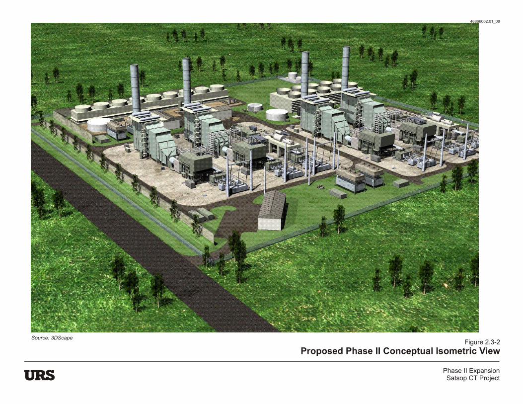
Figure 2.3-2
Proposed Phase II Conceptual Isometric View
Phase II ExpansionSatsop CT Project
Source: 3DScape
46866002.01_08

Figure 2.3-3
Plant ConfigurationPhase II ExpansionSatsop CT Project

Figure 2.3-4
Site PlanPhase II ExpansionSatsop CT Project
KEY

Figure 2.3-5Plant Elevation
Phase II ExpansionSatsop CT Project

46
86
60
02
.01
_3
8.c
dr
ExistingOutfall
Structure
ExistingRanney Wells
CT ProjectEffluent
CT ProjectWaterSupply
Water SupplyPipeline
PlantSite
Existing DischargePipeline
Interconnection
Figure 2.3-6
Process WaterConceptual Flow Diagram
Phase II ExpansionSatsop CT Project