Embed Size (px)
Citation preview
More than
Zack Taylor, Stellar Energy, USA,
presents a comparison of mechanical chilling
versus adiabatic cooling as augmentation methods for
LNG production.
megawatts
As gas turbines are commonly used in the LNG liquefaction process, their ability to deliver efficient, consistent shaft power is critical to the predictable production of LNG.
Ambient temperature has a significant impact on the performance of gas turbines. The power output of the gas turbine is dependent on the mass of air that is compressed, combusted and expanded through the turbine. A gas turbine is a fixed volumetric flow machine, and therefore the turbine’s inlet air density proportionally impacts power output. As the air temperature rises, yielding a lower air density, mass flow decreases and thus power output is reduced. LNG plants located in climates where ambient temperature exceeds the turbine’s ISO-rated inlet air design point experience degraded performance and unpredictable power output, turning the gas turbine into a production bottleneck.
Power augmentation technologies that alleviate output degradation, such as turbine inlet air chilling, evaporative cooling, fogging and wet compression, are often compared on power output gains alone. However, a thorough risk-benefit analysis comparing these technologies across the entire lifecycle of the augmentation systems – as well as the gas turbine – reveals advantages of turbine inlet air chilling (TIAC) technology.
Inlet cooling technologiesFor LNG plants, TIAC can maintain a constant inlet air temperature, delivering robust gas turbine performance and thereby stabilising production. A TIAC system consists of a chilled water plant, which sends chilled water as a secondary refrigerant to coils placed in the filter house downstream of the high-efficiency filtration system. This water is chilled via a vapour compression or vapour absorption chiller in a closed-loop system that avoids releasing any foreign contaminants into the gas turbine
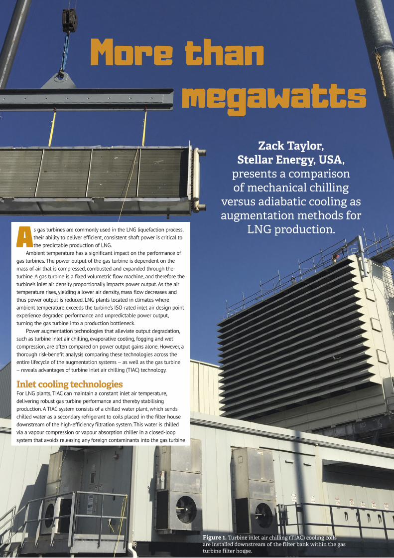
Figure 1. Turbine inlet air chilling (TIAC) cooling coils are installed downstream of the filter bank within the gas turbine filter house.

Reprinted from February 2020
inlet flow stream. The condensate that forms on the coils, as a byproduct of the chilling process, is captured via multi-stage drift eliminators and is gravity-fed to either a plant drain or a collection tank for other uses.
Various methods of adiabatic cooling exist, but all operate on the same working principle: cool the inlet ambient air from the dry bulb temperature to the wet bulb temperature limit by increasing the humidity of the air. Evaporative coolers spray water onto a saturated media, while foggers serve to humidify the air by the direct injection of fine mist into the flow stream. Wet compression sprays a high volume of water – beyond the saturation point – to allow the water to evaporate in the forward compressor stages. All of these adiabatic, water-injection systems require a significant supply of high-quality, demineralised water in order to operate reliably. Since these are open-loop cooling systems, these systems are more prone to water contamination, which can transfer foreign contaminants onto the gas turbine components.
Gas turbine output and efficiency impactsTIAC provides up to 35% output gains on hot days (independent of relative humidity) and 5% improvement in heat rate, with up to 15% additional annualised output. Output is predictable and consistent for the entire year above nameplate capacity. Furthermore, case studies on commonly applied liquefaction technologies show a shaft horsepower to LNG production ratio approaching 1:1.
Meanwhile, adiabatic methods provide up to 15% output gains on hot days with a 3% improvement in heat rate at entitlement. Since adiabatic methods can only cool to the wet bulb temperature, even at a new and clean effectiveness of 85%, output is still subject to weather variations, with up to 20% output variation in the summer months.
Resources requiredThe primary resource required to operate a TIAC system for LNG production is electricity to power mechanical, centrifugal-compressor chillers and associated pump and fan motors. Alternatively, a vapour absorption chiller can be used in the chiller plant if a surplus heat source (e.g. gas turbine exhaust) or surplus fuel source (to be used with a gas-fired vapour absorption chiller) is available. In the LNG liquefaction markets, an electrically-powered, centrifugal compressor chiller is the most
robust solution as it requires a small charge of an ASHRAE Class A-1 Safety Group hydrofluoroolefin (HFO) refrigerant.
The primary resource required in a water injection passive cooling system is high-quality, demineralised water – up to 140 gal./min. for a GE 9E. Complex reverse osmosis systems with multiple stages are required to sufficiently purify and polish the injected water to an acceptable level. In regions with limited water supply or without existing demineralised water production, which is common at LNG liquefaction sites, water injection cooling becomes unrealistic due to the lack of water resources. Electricity is also required to power pumps in the demineralised water plant and pumps at the filter house.
Impacts to the gas turbineTurbine cold section impactsTurbine inlet air chilling is the only gas turbine augmentation technology that reliably and predictably creates the improved performance and ideal component operational conditions. The gas turbine inlet temperature is set no lower than 8°C to mitigate any potential ice formation. Ambient variation is eliminated such that the gas turbine is operating consistently at design conditions established by the original equipment manufacturer (OEM).
In contrast, in order to achieve power gains through adiabatic cooling, water is either presented to the inlet air via wetted media, misted via nozzles in an attempt to evaporate the injected water, or ‘over-sprayed’ so that water does not evaporate prior to entering the gas turbine compressor. All of these adiabatic methods can introduce contaminants into the flow path that carry over into the gas turbine.
The key adverse effects and subsequent gas turbine system risks due to water injection are as follows:
z Compressor fouling due to wet corrosion – consequences include aerodynamic instability leading to increased rotating stall and compressor performance degradation.
z Compressor blade erosion/pitting due to the water droplets present in the flow stream – consequences include performance degradation, aerodynamic instability, rotating stall risk and compressor surge margin reduction.
z Increased loading of the forward stage compressor blades – consequences include increased dynamic stresses on the compressor blades leading to increased blade failure risk due to high cycle fatigue and higher potential for aeroelastic instability (flutter).
z Imbalanced stage loading of the compressor as a result of injected water evaporating across multiple stages in the compressor – consequences include expanded rotating stall and subsequent compressor surge margin reduction.
Water injection can compound the negative impacts on compressor surge margin since the inter-stage aerodynamic loading is altered to an off-design point, which results in approximately 5% stall margin reduction and, over time, degraded compressor blades can reduce the surge margin by an additional 5%. These adverse impacts to surge margin are net additive. Simply put, it is probable that the entire compressor surge margin, which is commonly designed to approximately 10%, will be consumed due to prolonged water injection.
The ultimate system risk associated with the aforementioned consequences of water injection — beyond degraded performance — is a major unplanned outage of the gas turbine. As the strongest
Figure 2. Adiabatic water injection methods employ atomiser nozzles that spray water at a droplet size of 10 – 20 microns.

Reprinted from February 2020
negative influence is at the forward-most stages of the gas turbine compressor, a failure of these components assuredly would result in catastrophic failure of the entire gas turbine. A failure of this nature would require months of outage to fully replace the rotor, much of the stator components and any equipment downstream of the turbine such as the exhaust diffuser. LNG liquefaction plants are often considered ‘mission-critical’, where 24 hours per day, 365 days a year, full-time operation is commonplace. The increased outage risks associated with water injection based augmentation can result in severe production and revenue shortfalls.
Turbine hot section impactsMuch the same as the TIAC system reduces the inlet temperatures to the compressor, it similarly reduces flow path temperatures in the hot section of the gas turbine by as much as 28°C. This reduction in flow path temperatures and associated turbine blade metal temperatures results in a significant improvement in component lifecycles for thermally sensitive failure modes, such as creep and low cycle fatigue. The net result to the gas turbine plant is longer intervals, fewer component replacements, shorter turbine component replacement outages and reduced risk to major unplanned outages.
Conversely, since water injection cooling methods increase the vapour content in the flow path, they tend to increase the metal temperatures of hot section components, such as turbine blades
and vanes. Generally, for a given temperature, the higher the vapour content, the higher the heat transfer coefficient, i.e. more heat is transferred to the blades and vanes. This effect is particularly sensitive to E-class gas turbines, which feature turbine blades and vanes with minimal or no internal cooling. One study, performed by Brun and Kurz,1 calculated a 12% reduction in hot gas path component life due to water injection cooling alone. Brun and Kurz concluded that: “the hot-section flow elements are optimised for a design point, where even small increases in surface metal temperature will lead to rapid hot oxidation of the turbine, i.e. these gas turbines are not designed for the increased heat load experienced when utilising evaporative cooling devices and rapid failure will occur.”1
Lifecycle performanceAugmentation equipmentTIAC systems have been in operation since the 1980s, with installations still meeting the target turbine inlet air temperatures. Industry history shows low failure rates due to the closed-loop systems. Compared to open-loop water injection systems where water quality must be constantly monitored and tuned, the closed-loop TIAC system demands significantly less operational support and maintenance oversight.
While the primary equipment is relatively simple, there are widespread examples of water injection nozzle failures in fogging and wet compression systems. Maintaining a microscopic droplet size (10 – 20 microns) is critical to the performance of the system. These nozzles are particularly susceptible to fouling due to the miniature size of the components as compared to the industrial gas turbine. Fouled nozzles will increase the droplet size and significantly increase the risk of blade erosion and pitting. This risk is possible even if water standards are maintained according to OEM requirements. Adiabatic cooling media has a propensity to foul as do all filters. The result is that a new and clean effectiveness of 85% can degrade to 70% or lower within one year of operation. Typical filter house media replacement for these adiabatic systems is required every five to seven years, which necessitates significant downtime of the gas turbine and, consequently, LNG production.
How the technologies affect gas turbine componentsThe TIAC system mimics cold day performance, which has not only positive performance impacts, but also improves the reliability, availability and maintainability of the gas turbine. This is accomplished by keeping the inlet air temperature, and subsequently the compressor and turbine flow path temperatures, at a steady, cold-day level (typically 8 – 13°C). TIAC also avoids the need for any severe operation modes, such as overfiring, as a means to achieve additional power. GE Power’s Heavy-Duty Gas Turbine Operating and Maintenance Considerations document (GER-3620M) provides equations that calculate the peak fire severity factor.2 For example, an overfire of 17°C (a typical amount of overfiring that would increase in a 5% increase in HP) would result in an hours-based severity factor of two in a F-class machine, which equates to a 50% component life capability degradation for the hours the machine is overfired.
GE’s GER-3620M also cautions the use of water injection (fogging or evaporative cooling) as it could result in “compressor corrosion, erosion fouling and material property degradation.”2 The document further states that if the environment is saline or acidic,
Figure 3. Excessive water injection can lead to erosion and pitting of the compressor blades, as well as other gas turbine component fouling.
Figure 4. TIAC provides stable and consistent LNG production year round.

blade pitting can result with a “material strength reduction to 40% of its original value.”2
Physical conditions such as these are what have led gas turbine OEMs to prohibit adiabatic and injection methods of inlet augmentation on certain models within their fleets.
What does this mean in terms of LNG production?For LNG plants, TIAC systems using mechanical chilling can be an easily implemented, cost-effective method of optimising liquefaction, stabilising production and increasing reliability and availability of the gas turbine. By using TIAC to maintain a constant inlet air temperature, gas turbine performance becomes significantly more predictable, thus allowing for the refrigeration compressors to operate efficiently in the narrow power band.
As TIAC is the only indirect method of cooling the gas turbine inlet air, it saves on water consumption, increases the lifespan of components throughout the entire gas turbine and has no degradation on a humid day. TIAC therefore produces a reliable and stable annual shaft power that can be depended upon every hour of every day in the year for predictable production.
Passive cooling via water injection remains subject to ambient condition variation and is particularly resource dependent, requiring complex components inside the filter house and vast amounts of demineralised water, which require both close maintenance and supervision to operate properly. When retrofitted to an existing engine, which has already experienced some degradation, the gas turbine reliability risks of injecting water into the flow stream become compounded, resulting in increased lifecycle costs and outages for the liquefaction plant.
References1. KURZ, R. and BRUN, K., ‘Gas Turbine Life Limiting Effects
of Inlet and Interstage Water Injection’, (2005), https://pdfs.semanticscholar.org/5b79/26bf82baa3b44134098680f9245d2c33fedd.pdf
2. JANAWITZ, J., MASSO, J. and CHILDS, C., ‘GE Power Heavy-Duty Gas Turbine Operating and Maintenance Considerations GER-3620M’, (2015), https://www.ge.com/content/dam/gepower-pgdp/global/en_US/documents/technical/unused%20assets/hdgt-operating-maintenance-considerations-report.pdf
stellar-energy.net
H E L P I N G O U R C U S TO M E R S M E E T T H E E N E R GY N E E D S O F TO M O R R O W
3,000+ megawatts recovered • 140+ projects in 14 countries • 20+ years in the industry • 100% performance tests passed
TURBINE INLET AIR CHILLING | DISTRICT COOLING | CENTRAL UTILITY PLANTS | COMBINED HEAT & POWERAmericas | MENA | Asia