Embed Size (px)
Citation preview

FOR OWNERS AND OPERATORS OF THE 242RT SEED EXPRESS


3
PRODUCT WARRANTY R E G I S T R A T I O N F O R M WARRANTY REGISTRATION This form must be filled out by the dealer and signed by both the dealer and the customer at the time of delivery. Please mail or fax the completed form for validation of the equipment registration.
Customer’s Name__________________________________________________
Address _________________________________________________________
City, State, Postal Code_________________________, _______, ___________
Phone Number (_______) _______- ___________
PRODUCT INFORMATION
Tender Model #___________ Serial Number #_______________________
DEALER INSPECTION REPORT
____Tender frame secured to trailer
____Check fuel level and gas shut-off
____Check crankcase oil level
____Start Honda eEngine
____Brake and lighting harness connection
____Remote throttle control functions
____Conveyor platform pivots correctly
____Lubricate unit where necessary
____Check air pressure in tires
____Electric brakes in working condition
____All guards/shields installed correctly
____All safety signs installed and intact
____Reflectors and lights clean and working
____Review safety and operating instructions
____Inspect customer’s hitch for 2-5/16”
ball/gooseneck hitch
____Verify receipt of all options ordered
I have thoroughly instructed the buyer on the above-described equipment, including review of the Operator’s Manual content, equipment care, adjustments, operational use, safety procedures, and applicable warranty
policy.
Dealer/Company Name____________________________________
City, State, Postal Code _________________________, _________, ______________
Dealer’s Signature______________________________________ Date ____/____/______
The above equipment and Operator’s Manual have been received by me, and I have been thoroughly instructed as
to care, adjustments, safe operation, and applicable warranty policy.
Owner’s Signature_____________________________________ Date ____/____/_______ 2902 Expansion Blvd. Storm Lake, Iowa 50588 Phone: 800-437-2334 Fax: 712-732-1028 Email: [email protected]
Cut
Her
e to
Rem
ove
Pag
e


5
2902 Expansion Blvd. Storm Lake, IA 50588 Phone: 712-732-1780
Fax: 712-732-1028
CERTIFICATE OF ORIGIN
LICENSING INFORMATION Date: ____/___/_______
DEALER:___________________________Business ___________________________Contact ___________________________Address ___________________________City, State, Zip
SOLD TO:___________________________Business ___________________________Contact ___________________________Address ___________________________City, State, Zip
TENDER MODEL # _________________________________________________________
TENDER WEIGHT __________________________________________________________
TENDER SERIAL # __________________________________________________________
TRAILER MODEL # _________________________________________________________
TRAILER SERIAL* # _________________________________________________________
TRAILER WEIGHT _____________________________________________ ____________
(*Only one serial number is issued for a complete tender package which will include the trailer. The trailer in these complete packages does not receive a separate serial number.)
Tender 110 BST Wagon 80110 1,004#
Tender 110 BST-T (trailer included) 80111 1,830#
Tender 220 BST Wagon 80220 1,866#
Tender 220 BST-T (trailer included) 80221 3,495#
Tender 240RT6 Wagon 80242 2,545#
Tender 240RT6-BWT (trailer included) 80247 4,475#
Tender 240RT6-T (trailer included) 80244 4,174#
Tender 240RT8 Wagon 80245 2,604#
Tender 240RT8-BWT (trailer included) 80241 4,534#
Tender 240RT8-T (trailer included) 80246 4,232#
Tender 240SE-T (trailer included) 80243 4,491#
Tender 375RT6 Wagon 80375 3,094#
Tender 375RT6-T (trailer included) 80378 5,636#
Tender 242RT (unibody) 80121 4,305#
Tender 375RT6-BWT (trailer included) 80374 5,942#
Tender 375RT8 Wagon 80376 3,106#
Tender 375RT8-BWT (trailer included) 80377 5,913#
Tender 375RT8-T (trailer included) 80379 5,607#
Tender T2SE-T (trailer included) 80201 2,002#
Tender T2-T (trailer included) 80200 1,555#
Tender T4SE Wagon 80401 2,803#
Tender T4SE-BWT (trailer included) 80403 4,833#
Tender T4SE-T (trailer included) 80402 4,431#
T6000ST Trailer 80311 826#
T14000ST Trailer 80307 1,628#
T1400GN Trailer 80342 1,663#
T21000ST Trailer 80308 2,501#
Tender 275BH-6DX (trailer included) 80203 4,807#
Tender 275GN-6DX (trailer included) 80204 5,399#
Tender 275-6DX 80202 4,188#
Tender 275BH-8DX (trailer included) 80206 4,924#
Tender 275GN-8DX (trailer included) 80207 5,517#
Tender 275-8DX 80205 4,305#
Tender 375BH-6DX (trailer included) 80332 5,029#
Tender 375GN-6DX (trailer included) 80333 5,623#
Tender 375-6DX 80331 4,343#
Tender 375BH-8DX (trailer included) 80335 5,146#
Tender 375GN-8DX (trailer included) 80336 5,739#
Tender 375-8DX 80334 4,460#
Cut
Her
e to
Rem
ove
Pag
e

7
IMPORTANT INFORMATION
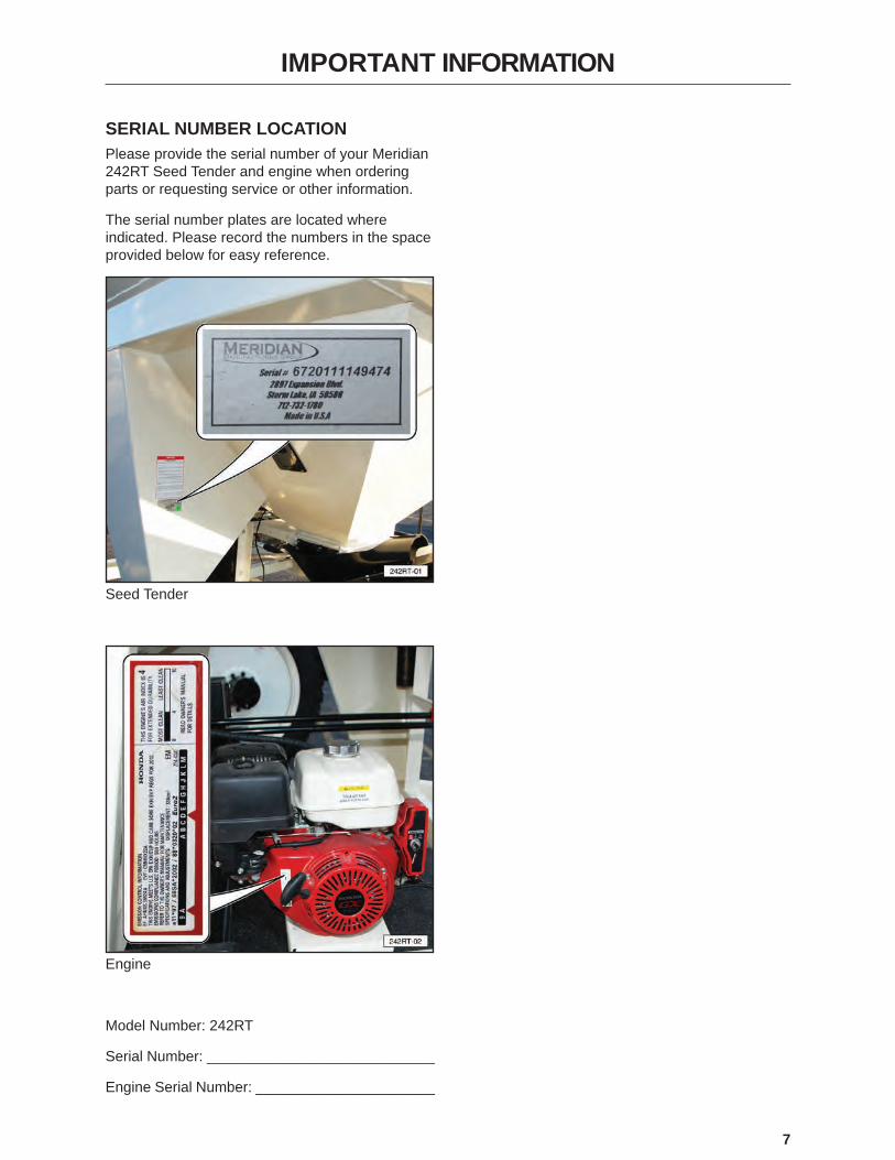
SERIAL NUMBER LOCATIONPlease provide the serial number of your Meridian 242RT Seed Tender and engine when ordering parts or requesting service or other information.
The serial number plates are located where indicated. Please record the numbers in the space provided below for easy reference.
Seed Tender
Engine
Model Number: 242RT
Serial Number: ____________________________
Engine Serial Number: ______________________
8
CONTENTS
1. INTRODUCTION . . . . . . . . . . . . . . . . . . . . . . . . . . . . . . . . . . . . . . . . . . . . . . . . . . . . . . . . . . 101.1 Congratulations . . . . . . . . . . . . . . . . . . . . . . . . . . . . . . . . . . . . 101.2 Operator Orientation . . . . . . . . . . . . . . . . . . . . . . . . . . . . . . . . . . 101.3 Owner/Operator . . . . . . . . . . . . . . . . . . . . . . . . . . . . . . . . . . . . 10
2. SAFETY. . . . . . . . . . . . . . . . . . . . . . . . . . . . . . . . . . . . . . . . . . . . . . . . . . . . . . . . . . . . . . . . . 112.1 General Safety . . . . . . . . . . . . . . . . . . . . . . . . . . . . . . . . . . . . . 122.2 Equipment Safety Guidelines . . . . . . . . . . . . . . . . . . . . . . . . . . . . . 132.3 Safety Training . . . . . . . . . . . . . . . . . . . . . . . . . . . . . . . . . . . . . 132.4 Safety Signs . . . . . . . . . . . . . . . . . . . . . . . . . . . . . . . . . . . . . . 14
2.4.1 How to Install Safety Signs . . . . . . . . . . . . . . . . . . . . . . . . . . 142.5 Preparation. . . . . . . . . . . . . . . . . . . . . . . . . . . . . . . . . . . . . . . 142.6 Operating Safety . . . . . . . . . . . . . . . . . . . . . . . . . . . . . . . . . . . . 142.7 Maintenance Safety . . . . . . . . . . . . . . . . . . . . . . . . . . . . . . . . . . 152.8 Lock-Out or Tag-Out Safety . . . . . . . . . . . . . . . . . . . . . . . . . . . . . . 152.9 Storage Safety . . . . . . . . . . . . . . . . . . . . . . . . . . . . . . . . . . . . . 162.10 Transport Safety . . . . . . . . . . . . . . . . . . . . . . . . . . . . . . . . . . . 162.11 Refuelling Safety . . . . . . . . . . . . . . . . . . . . . . . . . . . . . . . . . . . 162.12 Battery Safety. . . . . . . . . . . . . . . . . . . . . . . . . . . . . . . . . . . . . 162.13 Sign-Off Form. . . . . . . . . . . . . . . . . . . . . . . . . . . . . . . . . . . . . 17
3. SAFETY SIGNS. . . . . . . . . . . . . . . . . . . . . . . . . . . . . . . . . . . . . . . . . . . . . . . . . . . . . . . . . . . 183.1 Safety Sign Locations . . . . . . . . . . . . . . . . . . . . . . . . . . . . . . . . . 19
4. SPECIFICATIONS. . . . . . . . . . . . . . . . . . . . . . . . . . . . . . . . . . . . . . . . . . . . . . . . . . . . . . . . . 21 4.1 Overall 242RT Seed Tender
Specifications . . . . . . . . . . . . . . . . . . . . . . . . . . . . . . . . . . . 214.2 Bolt Specifications . . . . . . . . . . . . . . . . . . . . . . . . . . . . . . . . . . . 22
4.2.1 Bolt Torque Values . . . . . . . . . . . . . . . . . . . . . . . . . . . . . . . 224.2.2 Grade Markings Chart . . . . . . . . . . . . . . . . . . . . . . . . . . . . . 22
5. MACHINE COMPONENTS AND CONTROLS . . . . . . . . . . . . . . . . . . . . . . . . . . . . . . . . . . . 235.1 Component Nomenclature and Location. . . . . . . . . . . . . . . . . . . . . . . . 23
5.1.1 Hydraulic Cylinder Check Valves . . . . . . . . . . . . . . . . . . . . . . . . 245.1.2 Conveyor Belt Speed Adjustment. . . . . . . . . . . . . . . . . . . . . . . . 24
5.2 Engine and Controls . . . . . . . . . . . . . . . . . . . . . . . . . . . . . . . . . . 255.2.1 Electrical System Key Switch . . . . . . . . . . . . . . . . . . . . . . . . . . 255.2.2 Fuel Controls . . . . . . . . . . . . . . . . . . . . . . . . . . . . . . . . . . 255.2.3 Battery (12 Volt). . . . . . . . . . . . . . . . . . . . . . . . . . . . . . . . . 25
6. PRE-OPERATING INSTRUCTIONS . . . . . . . . . . . . . . . . . . . . . . . . . . . . . . . . . . . . . . . . . . . 266.1 Machine Break-In Period. . . . . . . . . . . . . . . . . . . . . . . . . . . . . . . . 26
6.1.1 Before Starting . . . . . . . . . . . . . . . . . . . . . . . . . . . . . . . . . 266.1.2 Inspections for 1/2, 5, and 10 Hours . . . . . . . . . . . . . . . . . . . . . . 26
6.2 Pre-Operation Checklist . . . . . . . . . . . . . . . . . . . . . . . . . . . . . . . . 26
7. OPERATION . . . . . . . . . . . . . . . . . . . . . . . . . . . . . . . . . . . . . . . . . . . . . . . . . . . . . . . . . . . . . 277.1 Connecting the Trailer . . . . . . . . . . . . . . . . . . . . . . . . . . . . . . . . . 27
7.1.1 Bumper Hitch . . . . . . . . . . . . . . . . . . . . . . . . . . . . . . . . . . 277.2 Opening and Closing Roll-Up Tarp. . . . . . . . . . . . . . . . . . . . . . . . . . . 287.3 Operation. . . . . . . . . . . . . . . . . . . . . . . . . . . . . . . . . . . . . . . . 29
7.3.1 Loading (Filling the Seed Tender). . . . . . . . . . . . . . . . . . . . . . . . 297.3.2 Unloading (Filling the Planter) . . . . . . . . . . . . . . . . . . . . . . . . . 30
8. STORAGE . . . . . . . . . . . . . . . . . . . . . . . . . . . . . . . . . . . . . . . . . . . . . . . . . . . . . . . . . . . . . . . 338.1 General Information . . . . . . . . . . . . . . . . . . . . . . . . . . . . . . . . . . 338.2 Placing in Storage . . . . . . . . . . . . . . . . . . . . . . . . . . . . . . . . . . . 338.3 Removing from Storage . . . . . . . . . . . . . . . . . . . . . . . . . . . . . . . . 33
9
9. MAINTENANCE . . . . . . . . . . . . . . . . . . . . . . . . . . . . . . . . . . . . . . . . . . . . . . . . . . . . . . . . . . 349.1 Lubrication . . . . . . . . . . . . . . . . . . . . . . . . . . . . . . . . . . . . . . . 34
9.1.1 Grease Fitting Locations. . . . . . . . . . . . . . . . . . . . . . . . . . . . 34
10. SERVICE PROCEDURES. . . . . . . . . . . . . . . . . . . . . . . . . . . . . . . . . . . . . . . . . . . . . . . . . . 3510.1 Hydraulic System . . . . . . . . . . . . . . . . . . . . . . . . . . . . . . . . . . . 35
10.1.1 Hydraulic Oil Change . . . . . . . . . . . . . . . . . . . . . . . . . . . . . 3510.1.2 Hydraulic Manifold . . . . . . . . . . . . . . . . . . . . . . . . . . . . . . . 3510.1.3 Hydraulic Motor Coupling . . . . . . . . . . . . . . . . . . . . . . . . . . . 35
10.2 Engine . . . . . . . . . . . . . . . . . . . . . . . . . . . . . . . . . . . . . . . . 3610.2.1 Approved Fuel . . . . . . . . . . . . . . . . . . . . . . . . . . . . . . . . . 3610.2.2 Engine Oil . . . . . . . . . . . . . . . . . . . . . . . . . . . . . . . . . . . 3610.2.3 Change Engine Oil . . . . . . . . . . . . . . . . . . . . . . . . . . . . . . 3610.2.4 Clean Air Cleaner . . . . . . . . . . . . . . . . . . . . . . . . . . . . . . . 37
10.3 Belt Delivery Tube . . . . . . . . . . . . . . . . . . . . . . . . . . . . . . . . . . 3710.3.1 Unplugging . . . . . . . . . . . . . . . . . . . . . . . . . . . . . . . . . . 3710.3.2 Belt Tension Adjustment . . . . . . . . . . . . . . . . . . . . . . . . . . . . 3710.3.3 Belt Tracking Adjustment . . . . . . . . . . . . . . . . . . . . . . . . . . . 3810.3.4 Belt Replacement . . . . . . . . . . . . . . . . . . . . . . . . . . . . . . . 38
10.4 Trailer Break-Away System . . . . . . . . . . . . . . . . . . . . . . . . . . . . . . 3910.4.1 Testing the Battery. . . . . . . . . . . . . . . . . . . . . . . . . . . . . . . 3910.4.2 Changing Battery . . . . . . . . . . . . . . . . . . . . . . . . . . . . . . . 40
10.5 Wheel Bolt Torque Requirements. . . . . . . . . . . . . . . . . . . . . . . . . . . 4010.6 FENDER AND AXLE Hold-Down Bolts . . . . . . . . . . . . . . . . . . . . . . . . 4010.7 Service Record Chart . . . . . . . . . . . . . . . . . . . . . . . . . . . . . . . . . 4010.8 Service Checks . . . . . . . . . . . . . . . . . . . . . . . . . . . . . . . . . . . . 42
10.8.1 Daily (8 Hours). . . . . . . . . . . . . . . . . . . . . . . . . . . . . . . . . 4210.8.2 Weekly (50 Hours). . . . . . . . . . . . . . . . . . . . . . . . . . . . . . . 4210.8.3 Annually (400 Hours) . . . . . . . . . . . . . . . . . . . . . . . . . . . . . 42
10.9 Axle Maintenance . . . . . . . . . . . . . . . . . . . . . . . . . . . . . . . . . . . 4310.9.1 First 200 Miles . . . . . . . . . . . . . . . . . . . . . . . . . . . . . . . . . 4310.9.2 3,000 Miles or 3 Months . . . . . . . . . . . . . . . . . . . . . . . . . . . . 4310.9.3 6,000 Miles or 6 Months . . . . . . . . . . . . . . . . . . . . . . . . . . . . 4310.9.4 12,000 Miles or 12 Months . . . . . . . . . . . . . . . . . . . . . . . . . . 43
10.10 Tires . . . . . . . . . . . . . . . . . . . . . . . . . . . . . . . . . . . . . . . . . 4310.11 Welding Repairs . . . . . . . . . . . . . . . . . . . . . . . . . . . . . . . . . . . 43
11. OEM LITERATURE . . . . . . . . . . . . . . . . . . . . . . . . . . . . . . . . . . . . . . . . . . . . . . . . . . . . . . . 4411.1 Honda® Engine . . . . . . . . . . . . . . . . . . . . . . . . . . . . . . . . . . . . 4411.2 Retractable Compartment Tarp . . . . . . . . . . . . . . . . . . . . . . . . . . . . 4411.3 Axle . . . . . . . . . . . . . . . . . . . . . . . . . . . . . . . . . . . . . . . . . . 45
12. TROUBLESHOOTING . . . . . . . . . . . . . . . . . . . . . . . . . . . . . . . . . . . . . . . . . . . . . . . . . . . . 4612.1 Troubleshooting Chart . . . . . . . . . . . . . . . . . . . . . . . . . . . . . . . . 46
13. WARRANTY . . . . . . . . . . . . . . . . . . . . . . . . . . . . . . . . . . . . . . . . . . . . . . . . . . . . . . . . . . . . 4713.1 Warranty Statement . . . . . . . . . . . . . . . . . . . . . . . . . . . . . . . . . . 47
14. PARTS. . . . . . . . . . . . . . . . . . . . . . . . . . . . . . . . . . . . . . . . . . . . . . . . . . . . . . . . . . . . . . . . . 4814.1 242RT Seed Tender Tarp kit and view window . . . . . . . . . . . . . . . . . . . . 4914.2 242RT Seed Tender decals, hitch and lights. . . . . . . . . . . . . . . . . . . . . . 5014.3 242RT hydraulics . . . . . . . . . . . . . . . . . . . . . . . . . . . . . . . . . . . 5214.4 242RT Conveyor Swivel, Fender, And Axle . . . . . . . . . . . . . . . . . . . . . . 5414.5 242RT COMPARTMENT SLIDE GATE VALVES . . . . . . . . . . . . . . . . . . . 5614.6 242RT CONVEYOR - LOWER END. . . . . . . . . . . . . . . . . . . . . . . . . . 5814.7 242RT CONVEYOR TUBE AND DAMPENER ASSEMBLY . . . . . . . . . . . . . . 6014.8 242RT DISCHARGE HOOD . . . . . . . . . . . . . . . . . . . . . . . . . . . . . . 62

10
1. INTRODUCTION
1.1 CONGRATULATIONSCongratulations on your choice of a Meridian Manufacturing Group 242RT Bulk Seed Tender to complement your seed delivery system in your farming operation. This equipment has been designed and manufactured to meet the exacting standards for such equipment in the agricultural industry and will keep your seed delivery system at optimum efficiency.
The Bulk Seed Tender system is designed to handle any kind of bulk seed, quickly transport it, and then transfer it into planters and drills, as required. This unit is designed to not only off-load bulk seed into the planting equipment, but it can also load itself from a bulk seed storage container or truck.
Safe, efficient, and trouble‑free operation of your Bulk Seed Tender requires that you and anyone else who will be operating or maintaining the machine, read and understand the Safety, Operation, Maintenance, and Troubleshooting information contained within this Operator’s Manual.
This manual covers the 242RT model manufactured by Meridian Manufacturing Group, Inc. Use the Table of Contents and Index as a guide to locate required information.
1.2 OPERATOR ORIENTATIONThe directions left, right, front, and rear, as mentioned throughout this manual, are as seen from the truck drivers’ seat and facing in the direction of travel.
1.3 OWNER/OPERATORIt is the responsibility of the owner or operator to read this manual and to train all other operators before they start working with the machine. Follow all safety instructions exactly. Safety is everyone’s business. By following recommended procedures, a safe working environment is provided for the operator, bystanders, and the area around the work site. Untrained operators are not qualified and must not operate the machine.
In addition to the design and configuration of equipment, hazard control and accident prevention are dependent upon the awareness, concern, prudence, and proper training of personnel involved in the operation, transport, maintenance, and storage of equipment. It is the responsibility of the owner or operator to read this manual and to train all operators before they start working with the machine. Follow all safety instructions as laid out in this manual.
Keep this manual handy for easy reference and to pass on to new operators or owners. Call your Meridian Manufacturing Group, Inc. dealer if you need assistance, information, or additional copies of the manuals.
The information, specifications, and illustrations in this manual are those in effect at the time of printing. We reserve the right to change specifications or design at any time without notice.

11
2. SAFETY
The Safety Alert symbol identifies important safety messages on the Meridian Bulk Seed Tender Models and in the manual. When you see this symbol, be alert to the possibility of personal injury or death. Follow the instructions in the safety message.
If you have any questions not answered in this manual, require additional copies of the manual, or the manual is damaged, please contact your dealer or Meridian Manufacturing Group, 2902 Expansion Blvd., Storm Lake, Iowa, 50588, toll free 1-800-437-2334, phone (712) 732-1780, or fax (712) 732-1028.
SIGNAL WORDS:Note the use of the signal words DANGER, WARNING, and CAUTION with the safety messages. The appropriate signal word for each message has been selected using the following guidelines:
SAFETY ALERT SYMBOL
This Safety Alert symbol means ATTENTION! BECOME ALERT! YOUR SAFETY IS INVOLVED!
WHY IS SAFETY IMPORTANT TO YOU?3 Big Reasons
• Accidents Disable and Kill • • Accidents Cost •
• Accidents Can Be Avoided •
DANGER - Indicates an imminently hazardous situation that, if not avoided, will result in death or serious injury. This signal word is to be limited to the most extreme situations typically for machine components which, for functional purposes, cannot be guarded.
WARNING - Indicates a potentially hazardous situation that, if not avoided, could result in death or serious injury, and includes hazards that are exposed when guards are removed. It may also be used to alert against unsafe practices.
CAUTION - Indicates a potentially hazardous situation that, if not avoided, may result in minor or moderate injury. It may also be used to alert against unsafe practices.
WARNING DANGERCAUTION

12
YOU are responsible for the SAFE operation and maintenance of your Meridian Manufacturing Group Bulk Seed Tender. YOU must ensure that you and anyone else who is going to operate, maintain, or work around the Bulk Seed Tender be familiar with the operating and maintenance procedures and related SAFETY information contained in this manual. This manual will take you step-by-step through your working day and alert you to all good safety practices that should be adhered to while operating the Bulk Seed Tender system.
Remember, YOU are the key to safety. Good safety practices not only protect you but also the people around you. Make these practices a working part of your safety program. Be certain that EVERYONE operating this equipment is familiar with the recommended operating and maintenance procedures and follow all the safety precautions. Most accidents can be prevented. Do not risk injury or death by ignoring good safety practices.
• Bulk Seed Tender system owners must give operating instructions to operators or employees before allowing them to operate the machine, and then annually thereafter per OSHA (Occupational Safety and Health Administration) regulation 1928.57.
• The most important safety feature on this equipment is a SAFE operator. It is the operator’s responsibility to read and follow ALL Safety and Operating instructions in the manual. Most accidents can be avoided.
• A person who has not read and understood all operating and safety instructions is not qualified to operate the machine. An untrained operator exposes himself and bystanders to possible serious injury or death. Always be and stay alert to any possible unsafe operating or maintenance procedures or conditions.
• Do not modify the equipment in any way. Unauthorized modification may impair the function and/or safety of the components and systems and could affect the life of the equipment, possibly invalidating the warranty coverage.
• Think SAFETY! Work SAFELY!
2.1 GENERAL SAFETY1. Read and understand the Operator’s
Manual and all safety signs before operating, maintaining, adjusting, filling, unloading, or unplugging the Bulk Seed Tender system.
2. Have a first aid kit available for use should the need arise and know how to use it.
3. Have a fire extinguisher available for use should the need arise and know how to use it.
4. Do not allow riders.
5. When working around or operating this equipment, wear appropriate personal protective equipment. This list includes but is not limited to:
• A hard hat• Protective shoes with slip resistant soles• Protective goggles, glasses, or face shield • Heavy gloves and protective clothing• Respirator
6. Do not allow long hair, loose fitting clothing, or jewelry around equipment.
7. Install and secure all guards before starting.
8. STOP
Stop engine, remove ignition key, and wait for all moving parts to stop before servicing, repairing, adjusting, loading, filling, or unplugging.
9. do not
operatesigned by
date
WARNING
Establish a lock-out or tag-out policy for the work site. Be sure all personnel are trained in and follow all procedures. Lock-out or tag-out all power sources before working around loading/unloading equipment.
10. Clear the area of people, especially small children, before starting.
11. Review safety related items annually with all personnel who will be operating, using, or maintaining the Bulk Seed Tender system.

13
2.2 EQUIPMENT SAFETY GUIDELINES
1. Safety of the operator and bystanders is one of the main concerns in designing and developing a machine. However, every year many accidents occur which could have been avoided by a few seconds of thought and a more careful approach to handling equipment. You, the operator, can avoid many accidents by observing the following precautions in this section. To avoid personal injury or death, study the following precautions and insist those working with you, or for you, follow them.
2. In order to provide a better view, certain photographs or illustrations in this manual may show an assembly with a safety shield removed. However, equipment should never be operated in this condition. Keep all shields in place. If shield removal becomes necessary for repairs, replace the shield prior to use.
3. Never use alcoholic beverages or sedative drugs while operating this equipment. Consult your doctor about operating this machine while taking prescription medications.
4. Under no circumstances should young children be allowed to work with this equipment. Do not allow persons to operate or assemble this unit until they have read this manual and have developed a thorough understanding of the safety precautions and how it works. Review the safety instructions with all users annually.
5. This equipment is dangerous to children and persons unfamiliar with its operation. The operator should be a responsible, properly trained, and physically able person familiar with farm machinery and trained in this equipment’s operations. If the elderly are assisting with farm work, their physical limitations need to be recognized and accommodated.
6. Never exceed the limits of a piece of machinery. If its ability to do a job, or to do so safely, is in question - DON’T TRY IT.
7. Do not modify the equipment in any way. Unauthorized modification may result in serious injury or death and may impair the function and life of the equipment.
8. In addition to the design and configuration of this implement, including Safety Signs and Safety Equipment, hazard control and accident prevention are dependent upon the awareness, concern, prudence, and proper training of personnel involved in the operation, transport, maintenance, and storage of the machine. Refer to Safety Messages and operation instruction in each of the appropriate sections of the auxiliary equipment and machine Manuals. Note all Safety Signs affixed to the auxiliary equipment.
2.3 SAFETY TRAINING1. Safety is a primary concern in the design and
manufacture of our products. Unfortunately, our efforts to provide safe equipment can be wiped out by a single careless act of an operator or bystander.
2. In addition to the design and configuration of equipment, hazard control and accident prevention are dependent upon the awareness, concern, prudence, and proper training of personnel involved in the operation, transport, maintenance, and storage of this equipment.
3. The best safety feature is an informed, careful operator. It is the operator’s responsibility to read and comply with ALL Safety and Operating instructions in the manual. Accidents can be avoided.
4. Working with unfamiliar equipment can lead to injuries. Read this manual, as well as the manual for your auxiliary equipment, before assembling or operating to acquaint yourself with the machines. If this machine is used by any person other than yourself, it is your responsibility to make certain that the operator reads and understands the operator’s manuals and is instructed in safe and proper use.
5. Know your controls and how to immediately stop augers, conveyors, and any other auxiliary equipment in an emergency. Read this manual and the one provided with all auxiliary equipment.
6. Train all new personnel and review instructions frequently with employees. Be certain only a properly trained and physically able person will operate the machinery. A person who has not read and understood all operating and safety instructions is not qualified to operate the machine. An untrained operator exposes himself and bystanders to possible serious injury or death.

14
2.4 SAFETY SIGNS 1.
N INGAR Keep safety signs clean and legible at all times. Replace any safety sign or instruction sign that is missing or not legible. Refer to the Safety Sign Location section for additional information.
2. Replacement parts that displayed a safety sign should also display the current sign.
3. Replacement safety signs (labels) are available from your authorized Dealer Parts Department or the factory at no cost.
2.4.1 How to Install Safety Signs
• Be sure that the installation area is clean and dry.
• Be sure temperature is above 50°F (10°C).
• Determine exact position before you remove the backing paper.
• Remove the smallest portion of the split backing paper.
• Align the sign over the specified area and carefully press the small portion with the exposed sticky backing in place.
• Slowly peel back the remaining paper and carefully smooth the remaining portion of the sign in place.
• Small air pockets can be pierced with a pin and smoothed out using a piece of sign backing paper.
2.5 PREPARATION1. Never operate the seed delivery
system and auxiliary equipment until you have read and completely understand this manual, the auxiliary equipment Operator’s Manual, and each of the Safety Messages found on the safety signs on the delivery system and auxiliary equipment.
2. PROLONGED EXPOSURE TO LOUD NOISE MAY CAUSE PERMANENT HEARING LOSS! Motors or equipment can be noisy enough to cause permanent or partial hearing loss. We recommend that you wear hearing protection on a full-time basis if the noise in the operator’s position exceeds 80db. NOTE: Hearing loss from loud noise (tractors, chain saws, radios, and other such sources close to the ear) is cumulative over a lifetime with uncertain natural recovery.
3. Clear working area of debris, trash, or hidden obstacles that might be hooked or snagged, causing injury, damage, or tripping.
4. Operate only in daylight or good artificial light.
5. Be sure machine is properly attached to the trailer, adjusted, and in good operating condition.
6. Ensure that all guards, shielding, and safety signs are properly installed and in good condition.
7. Before starting, give the machine a “once over” for any loose bolts, worn parts, cracks, leaks, frayed belts, and make necessary repairs. Always follow maintenance instructions.
2.6 OPERATING SAFETY1. Make sure that anyone who will be
operating the Bulk Seed Tender system or working on or around the unit reads and understands all the operating, maintenance, and safety information in the operator’s manual.
2. Keep all bystanders, especially children, away from the machine when loading or unloading, or when authorized personnel are carrying out maintenance work.
3. do not
operatesigned by
date
WARNING
Establish a lock-out or tag-out policy for the work site. Be sure all personnel are trained in and follow all procedures. Lock-out or tag-out all power sources before servicing the unit or working around loading/unloading equipment.

15
4. STOP
Stop engine, remove ignition key, and wait for all moving parts to stop before servicing, repairing, adjusting, loading, filling, or unplugging.
5. Keep working area clean and free of debris to prevent slipping or tripping.
6. Do not allow riders on the trailer or frame when transporting.
7. Keep hands, feet, hair, and clothing away from rotating parts.
8. Do not place hands, fingers, or arms between moving parts.
9. Stay away from overhead power lines. Electrocution can occur without direct contact.
10. Install and secure all guards before starting.
11. Use care when climbing on frame or ladder to prevent slipping or falling.
12. Fasten frame securely to trailer before transporting.
13. Always empty compartment 2 first to prevent an unbalanced load. An unbalanced load can cause the tender to upend.
14. Review safety related items annually with all personnel who will be operating, using, or maintaining the seed delivery system.
2.7 MAINTENANCE SAFETY1. Good maintenance is your responsibility. Poor
maintenance is an invitation for trouble.
2. Follow good shop practices.
3. Ensure proper ventilation. Never operate the engine in a closed building. The exhaust fumes may cause asphyxiation.
4. STOP
Before working on this machine, shut off the engine and remove the ignition keys.
5. Never work under equipment unless it is securely blocked.
6.
Always use personal protection devices, such as eye, hand, and hearing protectors, when performing any service or maintenance.
7. OEM
Where replacement parts are necessary for periodic maintenance and servicing, genuine factory replacement parts must be used to restore your equipment to the original specifications. The manufacturer will not be responsible for injuries or damages caused by use of unapproved parts and/or accessories.
8. A fire extinguisher and first aid kit should be readily accessible while performing maintenance on this equipment.
9. Periodically tighten all bolts, nuts, and screws and ensure all cotter pins are properly installed to ensure the unit is in safe condition.
10. When completing a maintenance or service function, make sure all safety shields and devices are installed before placing the unit in service.
11. Turn OFF all electrical power and tag-out or lock-out the power source before performing any electrical test or before connecting or disconnecting valve coils or other electrical loads.
12. Never operate or test any function of the equipment when people are in an area of a potential crush hazard.
2.8 LOCK-OUT OR TAG-OUT SAFETY1.
do notoperate
signed by
date
WARNING
Establish a formal Lock-Out or Tag-Out program for your operation.
2. Train all operators and service personnel before allowing them to work around the seed delivery system.
3. do not
operatesigned by
date
WARNING
Provide tags on the machine and a sign-up sheet to record tag-out details.
16
2.9 STORAGE SAFETY1. Store the unit in an area away from human
activity.
2. Do not permit children to play on or around the stored machine.
3. Store the unit in a dry, level area. Support the frame with planks, if required.
2.10 TRANSPORT SAFETY1. Comply with local, state, and federal
laws governing safety and conveyance of farm machinery on public roads.
2. Ensure all lights, reflectors, and other lighting requirements are installed and in good working condition.
3. Ensure that the trailer is equipped with brakes that are in good working order. Be familiar with their operation.
4. Do not exceed a safe travel speed. Slow down for rough terrain and when cornering.
5. Fasten frame securely to trailer before transporting.
6. Be sure the trailer is securely hitched to the towing vehicle and a retainer is used through the hitch jaws. Always attach a safety chain between the hitch and the towing vehicle.
7. Stay away from overhead power lines. Electrocution can occur without direct contact.
8. Plan your route to avoid heavy traffic.
9. Install auger spout transport lock before transporting.
10. Do not drink and drive.
11. Be a safe and courteous driver. Yield to oncoming traffic in all situations, including narrow bridges, intersections, etc. Watch for traffic when operating near or crossing roadways.
12. Never allow riders on the tender or the trailer.
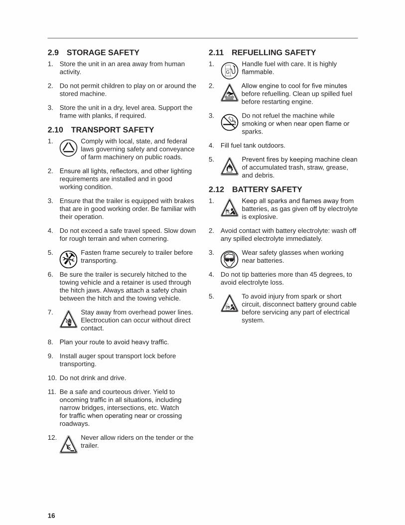
2.11 REFUELLING SAFETY1.
G
Handle fuel with care. It is highly flammable.
2. Allow engine to cool for five minutes before refuelling. Clean up spilled fuel before restarting engine.
3. Do not refuel the machine while smoking or when near open flame or sparks.
4. Fill fuel tank outdoors.
5. Prevent fires by keeping machine clean of accumulated trash, straw, grease, and debris.
2.12 BATTERY SAFETY1. Keep all sparks and flames away from
batteries, as gas given off by electrolyte is explosive.
2. Avoid contact with battery electrolyte: wash off any spilled electrolyte immediately.
3. Wear safety glasses when working near batteries.
4. Do not tip batteries more than 45 degrees, to avoid electrolyte loss.
5. To avoid injury from spark or short circuit, disconnect battery ground cable before servicing any part of electrical system.

17
2.13 SIGN-OFF FORMMeridian Manufacturing Group follows the general Safety Standards specified by the American Society of Agricultural Engineers (ASAE) and Occupational Safety and Health Administration (OSHA). Anyone who will be operating and/or maintaining the Meridian Manufacturing Group Bulk Seed Tender must read and clearly understand ALL Safety, Operating, and Maintenance information presented in this manual.
Do not allow anyone to operate this equipment until such information has been reviewed. Annually review this information before the season start-up.
SIGN-OFF FORMDate Employee’s Signature Employer’s Signature
Make these periodic reviews of SAFETY and OPERATION a standard practice for all of your equipment. We feel an untrained operator is unqualified to operate this machine.
A sign-off sheet is provided for your record keeping to show that all personnel who will be working with the equipment have read and understand the information in the Operator’s Manual and have been instructed in the operation of the equipment.

18
3. SAFETY SIGNS
The types of safety signs and locations on the equipment are shown in the following pages. Good SAFETY AWARENESS requires that you familiarize yourself with the various safety signs, the type of warning and the area, or a particular function related to that area.
REMEMBER - If safety signs have been damaged, removed, become illegible, or parts replaced without signs, new signs must be applied. New safety signs are available from your authorized dealer free of charge.
CAUTION
Read and understand the Operator's Manual before using.
• Review safety instructions annually.• Stop engine, remove ignition key, and wait for all moving parts
to stop before servicing, repairing, adjusting, loading, filling, or unplugging.
• Keep working area clean and free of debris to prevent slipping or tripping.
• Do not allow riders on the trailer or frame when transporting.• Only enter seed compartment when it is empty.• Keep hands, feet, hair, and clothing away from moving parts.• Do not place hands, arms, or body between seed box and frame
or lid to prevent pinching or crushing. Components can move unexpectedly.
• Do not place hands, fingers, or arms between unloading auger tube segments when placing in unloading configuration.
• Stay away from overhead power lines. Electrocution can occur without direct contact.
• Install and secure all guards before starting.• Use care when climbing on frame or ladder to prevent slipping
or falling.• Do not smoke when refuelling or working around machine.• Fasten frame securely to trailer before transporting.• Always empty compartment 2 first to prevent an unbalanced load.
An unbalanced load can cause hitch to upend.
19934
19
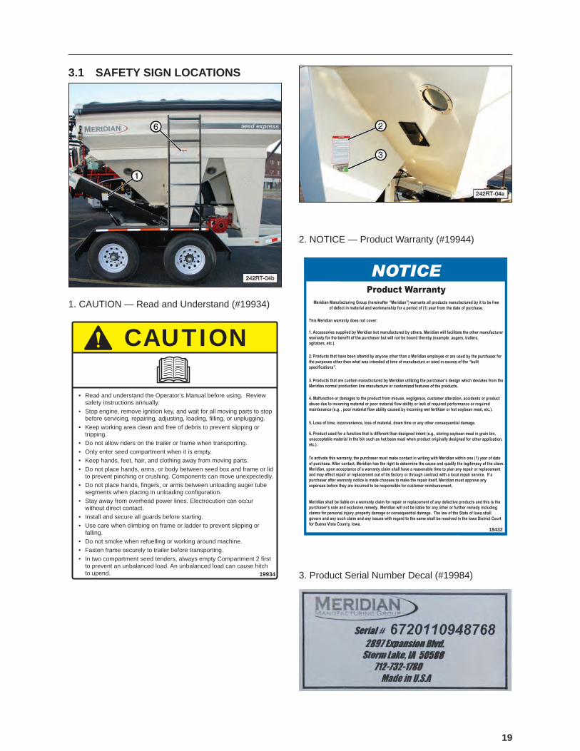
3.1 SAFETY SIGN LOCATIONS
1. CAUTION — Read and Understand (#19934)
CAUTION
19934
• Read and understand the Operator’s Manual before using. Review safety instructions annually.
• Stop engine, remove ignition key, and wait for all moving parts to stop before servicing, repairing, adjusting, loading, fi lling, or unplugging.
• Keep working area clean and free of debris to prevent slipping or tripping.
• Do not allow riders on the trailer or frame when transporting.• Only enter seed compartment when it is empty.• Keep hands, feet, hair, and clothing away from moving parts.• Do not place hands, arms, or body between seed box and frame or lid
to prevent pinching or crushing. Components can move unexpectedly.• Do not place hands, fi ngers, or arms between unloading auger tube
segments when placing in unloading confi guration.• Stay away from overhead power lines. Electrocution can occur
without direct contact.• Install and secure all guards before starting.• Use care when climbing on frame or ladder to prevent slipping or
falling.• Do not smoke when refuelling or working around machine.• Fasten frame securely to trailer before transporting.• In two compartment seed tenders, always empty Compartment 2 fi rst
to prevent an unbalanced load. An unbalanced load can cause hitch to upend.
2. NOTICE — Product Warranty (#19944)
18432
3. Product Serial Number Decal (#19984)

20
4. DANGER — Pinch Point (#20087)
5. WARNING — Rotating Parts (#19936)
19936
Do not place hands or fingers near rotating or moving parts.
6. WARNING — Fall Hazard (#19939)
FALLING HAZARD
19939
Avoid serious injury or death from falling:
• Grip the ladder with both hands when climbing to prevent slipping or falling.
• Keep rungs clean to prevent slipping.
7. WARNING — Hot Surface (#20088)
WARNINGBURN HAZARD
Hot surfaces or oil can cause severe burn
injuries.• Do not touch hydraulic
tank or hoses during operating.
• Avoid contact with hot oil.
21
4. SPECIFICATIONS
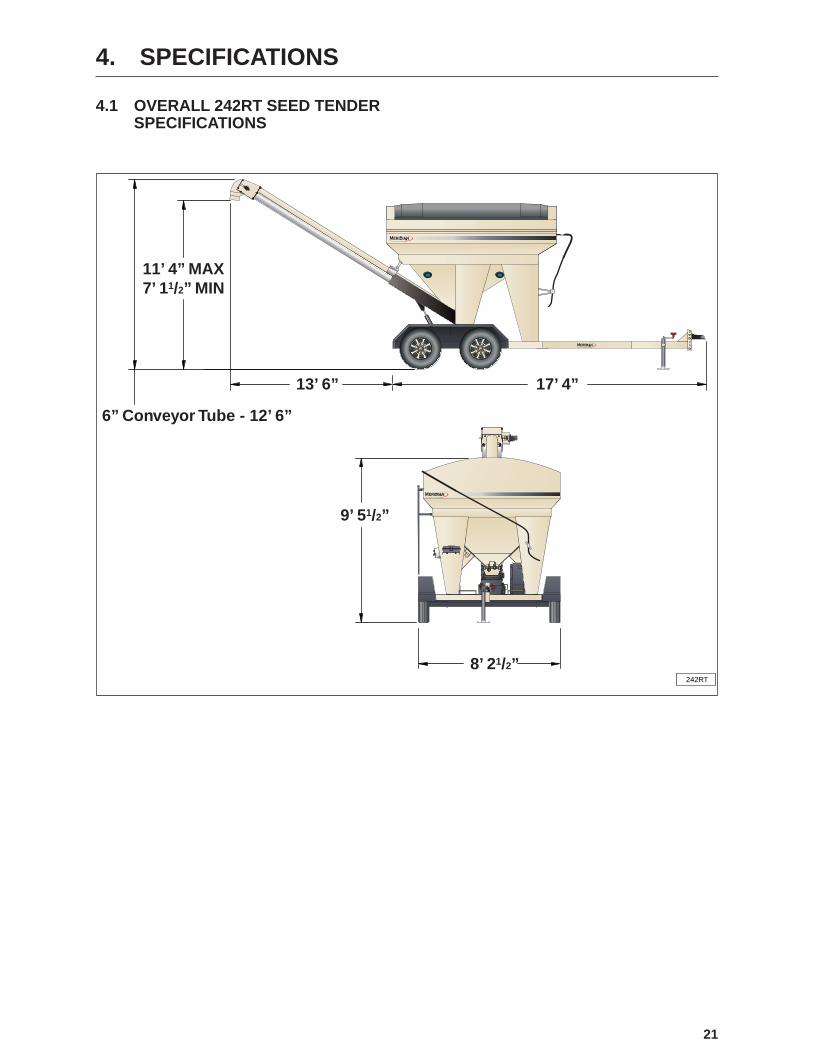
4.1 OVERALL 242RT SEED TENDER SPECIFICATIONS
8’ 21/2”
7’ 11/2” MIN11’ 4” MAX
13’ 6”
9’ 51/2”
6” Conveyor Tube - 12’ 6”
17’ 4”
242RT
22
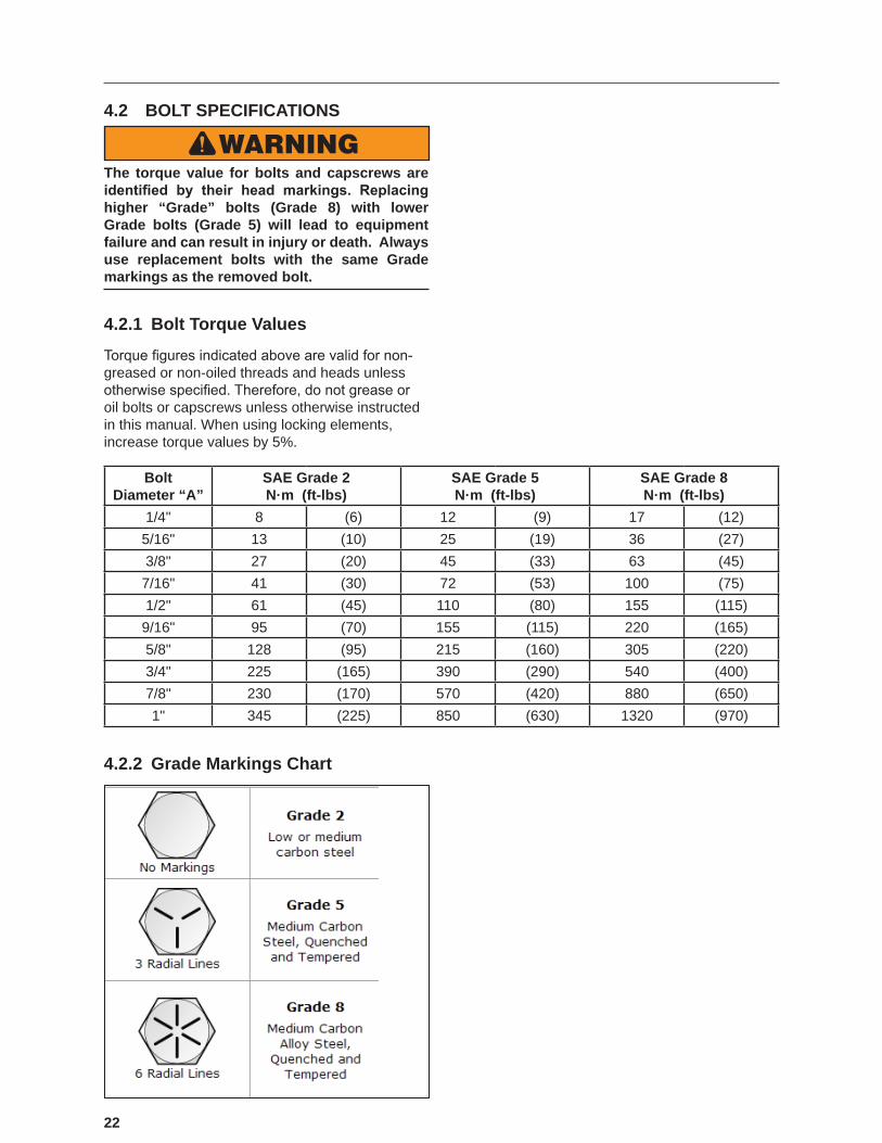
4.2 BOLT SPECIFICATIONS
WARNINGThe torque value for bolts and capscrews are identified by their head markings. Replacing higher “Grade” bolts (Grade 8) with lower Grade bolts (Grade 5) will lead to equipment failure and can result in injury or death. Always use replacement bolts with the same Grade markings as the removed bolt.
4.2.1 Bolt Torque Values
Torque figures indicated above are valid for non‑greased or non-oiled threads and heads unless otherwise specified. Therefore, do not grease or oil bolts or capscrews unless otherwise instructed in this manual. When using locking elements, increase torque values by 5%.
Bolt Diameter “A”
SAE Grade 2N·m (ft-lbs)
SAE Grade 5N·m (ft-lbs)
SAE Grade 8N·m (ft-lbs)
1/4" 8 (6) 12 (9) 17 (12)5/16" 13 (10) 25 (19) 36 (27)3/8" 27 (20) 45 (33) 63 (45)7/16" 41 (30) 72 (53) 100 (75)1/2" 61 (45) 110 (80) 155 (115)9/16" 95 (70) 155 (115) 220 (165)5/8" 128 (95) 215 (160) 305 (220)3/4" 225 (165) 390 (290) 540 (400)7/8" 230 (170) 570 (420) 880 (650)1" 345 (225) 850 (630) 1320 (970)
4.2.2 Grade Markings Chart

23
5. MACHINE COMPONENTS AND CONTROLS
5.1 COMPONENT NOMENCLATURE AND LOCATION
The Meridian 242RT Seed Express model is designed as bulk seed transfer unit to transfer large amounts of seed into a planter or drill.
The seed can be dumped into one of two compartments from a seed box or other means. The center-mounted conveyor (7) then transfers the seed from the compartments to a planter or drill. Slide gates (29) at the bottom of the compartments control the flow of seed into the conveyor.
A gasoline engine (40) mounted on the frame powers a hydraulic pump (38), which operates the hydraulic motor (9) for the conveyor. It also powers the cylinder (14) which raises and lowers the conveyor.
The conveyor is mounted on rotating platform (36) that rotates 180° from side-to-side. A spout (12) on the end of the conveyor allows for convenient distribution.
(1) Seed Tender Frame. (2) View Glass for Front Compartment. (3) Retractable Tarp. (4) Sample Gate for Rear Compartment. (5) View Glass for Rear Compartment. (6) Conveyor Transport Lock Mechanism. (7) Conveyor. (8) Conveyor Discharge Chute. (9) Hydraulic Motor for Conveyor. (10) Flexible Delivery Chute. (11) Conveyor On/Off Switch Control. (12) Delivery Spout. (13) Adjustable Valve to Control Conveyor Speed. (14) Hydraulic Cylinder to Raise and Lower Conveyor. (15) Conveyor Pivot System Lock. (16) Uni-body Frame.
(17) Compartment Access Ladder. (18) Retractable Tarp with Attached Actuator Handle (19) Latch Mechanism to Store Tarp Handle When Not In Use. (20) Push/Pull Handles to Control Bin Slide Gates. (21) Trailer Jack. (22) Trailer Break-Away Switch and Tether Cable. (23) Hitch Safety Chains. (24) Hitch to Receive Ball of Tow Vehicle. (25) Adjustable Height Hitch Bracket. (26) Electrical Plug for Trailer Lights.
(27) Hydraulic Valve to Raise/Lower Conveyor. (28) On/Off Solenoid Valve for Conveyor Drive Motor. (29) Bin Discharge Slide Gates (30) Dirty Filter Indicator. (31) Hydraulic Tank. (32) Tank Fill Cap. (33) Oil Level Sight Glass. (34) Hydraulic Oil Filter. (35) Conveyor Clean-out Access Door. (36) Conveyor Pivot Mechanism. (37) Push/Pull. Handles for Bin Slide Gates. (38) Hydraulic Pump. (39) Bell Housing with Coupler (connects engine to pump). (40) Gasoline Engine. (41) Electric Starter.
24
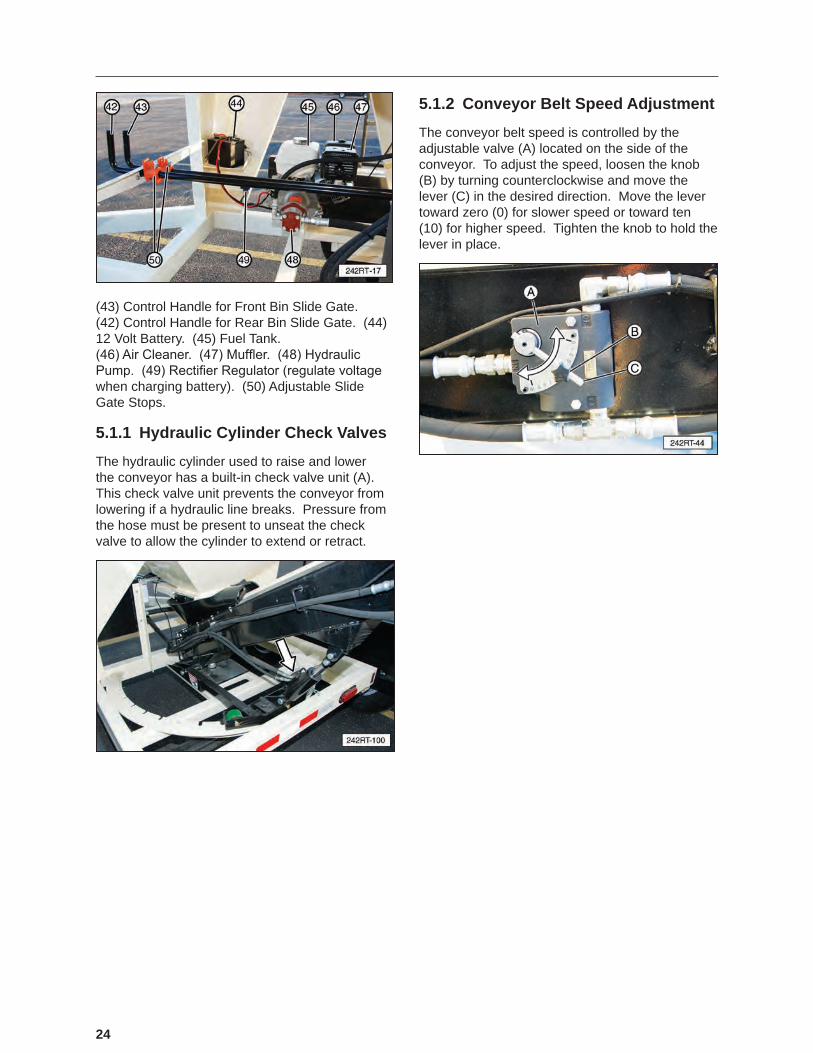
(43) Control Handle for Front Bin Slide Gate. (42) Control Handle for Rear Bin Slide Gate. (44) 12 Volt Battery. (45) Fuel Tank. (46) Air Cleaner. (47) Muffler. (48) Hydraulic Pump. (49) Rectifier Regulator (regulate voltage when charging battery). (50) Adjustable Slide Gate Stops.
5.1.1 Hydraulic Cylinder Check Valves
The hydraulic cylinder used to raise and lower the conveyor has a built-in check valve unit (A). This check valve unit prevents the conveyor from lowering if a hydraulic line breaks. Pressure from the hose must be present to unseat the check valve to allow the cylinder to extend or retract.
5.1.2 Conveyor Belt Speed Adjustment
The conveyor belt speed is controlled by the adjustable valve (A) located on the side of the conveyor. To adjust the speed, loosen the knob (B) by turning counterclockwise and move the lever (C) in the desired direction. Move the lever toward zero (0) for slower speed or toward ten (10) for higher speed. Tighten the knob to hold the lever in place.
25
5.2 ENGINE AND CONTROLSA Honda® engine is used with this unit. Always read the engine Operator’s Manual supplied with the seed tender for the detailed operating procedures.
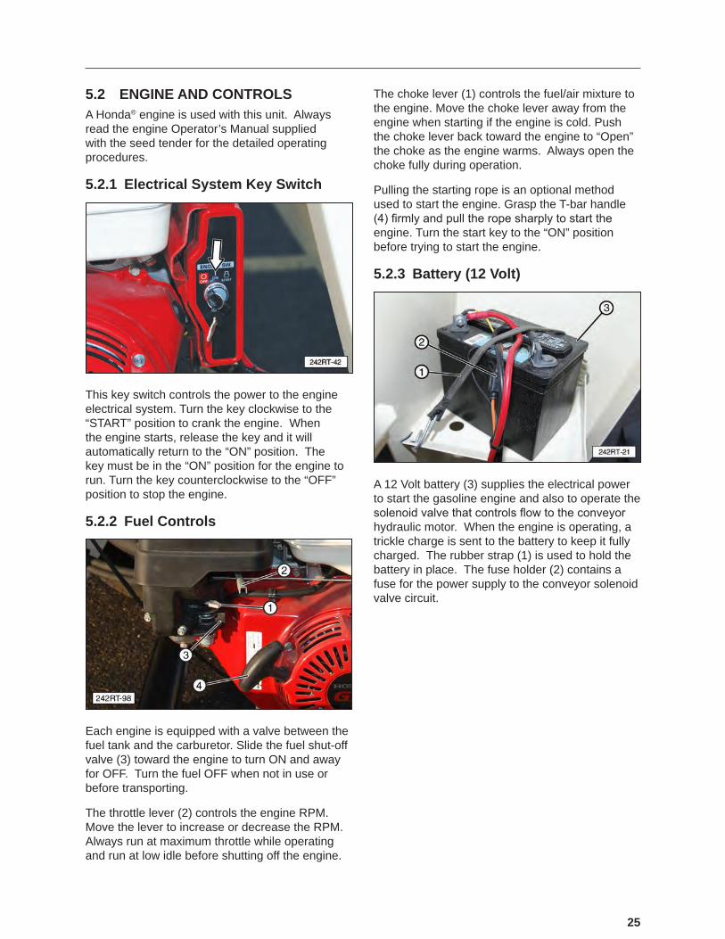
5.2.1 Electrical System Key Switch
This key switch controls the power to the engine electrical system. Turn the key clockwise to the “START” position to crank the engine. When the engine starts, release the key and it will automatically return to the “ON” position. The key must be in the “ON” position for the engine to run. Turn the key counterclockwise to the “OFF” position to stop the engine.
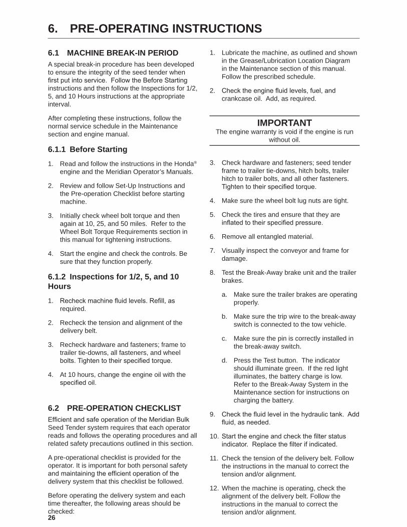
5.2.2 Fuel Controls
Each engine is equipped with a valve between the fuel tank and the carburetor. Slide the fuel shut-off valve (3) toward the engine to turn ON and away for OFF. Turn the fuel OFF when not in use or before transporting.
The throttle lever (2) controls the engine RPM. Move the lever to increase or decrease the RPM. Always run at maximum throttle while operating and run at low idle before shutting off the engine.
The choke lever (1) controls the fuel/air mixture to the engine. Move the choke lever away from the engine when starting if the engine is cold. Push the choke lever back toward the engine to “Open” the choke as the engine warms. Always open the choke fully during operation.
Pulling the starting rope is an optional method used to start the engine. Grasp the T-bar handle (4) firmly and pull the rope sharply to start the engine. Turn the start key to the “ON” position before trying to start the engine.
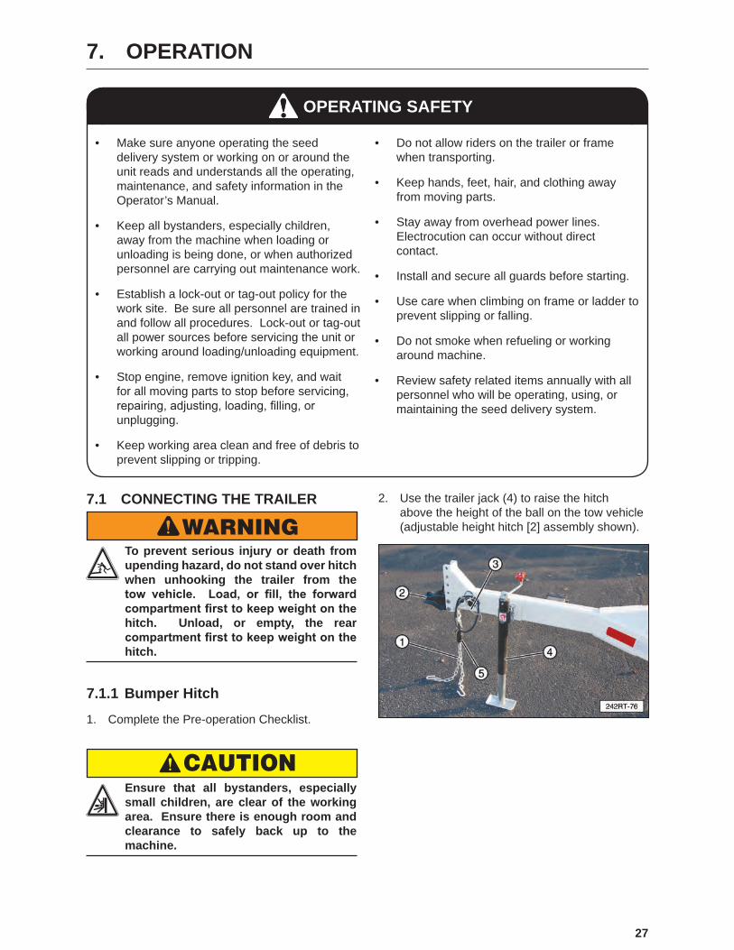
5.2.3 Battery (12 Volt)
A 12 Volt battery (3) supplies the electrical power to start the gasoline engine and also to operate the solenoid valve that controls flow to the conveyor hydraulic motor. When the engine is operating, a trickle charge is sent to the battery to keep it fully charged. The rubber strap (1) is used to hold the battery in place. The fuse holder (2) contains a fuse for the power supply to the conveyor solenoid valve circuit.
26
6. PRE-OPERATING INSTRUCTIONS
6.1 MACHINE BREAK-IN PERIODA special break-in procedure has been developed to ensure the integrity of the seed tender when first put into service. Follow the Before Starting instructions and then follow the Inspections for 1/2, 5, and 10 Hours instructions at the appropriate interval.
After completing these instructions, follow the normal service schedule in the Maintenance section and engine manual.
6.1.1 Before Starting
1. Read and follow the instructions in the Honda® engine and the Meridian Operator’s Manuals.
2. Review and follow Set-Up Instructions and the Pre-operation Checklist before starting machine.
3. Initially check wheel bolt torque and then again at 10, 25, and 50 miles. Refer to the Wheel Bolt Torque Requirements section in this manual for tightening instructions.
4. Start the engine and check the controls. Be sure that they function properly.
6.1.2 Inspections for 1/2, 5, and 10 Hours
1. Recheck machine fluid levels. Refill, as required.
2. Recheck the tension and alignment of the delivery belt.
3. Recheck hardware and fasteners; frame to trailer tie-downs, all fasteners, and wheel bolts. Tighten to their specified torque.
4. At 10 hours, change the engine oil with the specified oil.
6.2 PRE-OPERATION CHECKLISTEfficient and safe operation of the Meridian Bulk Seed Tender system requires that each operator reads and follows the operating procedures and all related safety precautions outlined in this section.
A pre-operational checklist is provided for the operator. It is important for both personal safety and maintaining the efficient operation of the delivery system that this checklist be followed.
Before operating the delivery system and each time thereafter, the following areas should be checked:
1. Lubricate the machine, as outlined and shown in the Grease/Lubrication Location Diagram in the Maintenance section of this manual. Follow the prescribed schedule.
2. Check the engine fluid levels, fuel, and crankcase oil. Add, as required.
IMPORTANTThe engine warranty is void if the engine is run
without oil.
3. Check hardware and fasteners; seed tender frame to trailer tie-downs, hitch bolts, trailer hitch to trailer bolts, and all other fasteners. Tighten to their specified torque.
4. Make sure the wheel bolt lug nuts are tight.
5. Check the tires and ensure that they are inflated to their specified pressure.
6. Remove all entangled material.
7. Visually inspect the conveyor and frame for damage.
8. Test the Break-Away brake unit and the trailer brakes.
a. Make sure the trailer brakes are operating properly.
b. Make sure the trip wire to the break-away switch is connected to the tow vehicle.
c. Make sure the pin is correctly installed in the break-away switch.
d. Press the Test button. The indicator should illuminate green. If the red light illuminates, the battery charge is low. Refer to the Break-Away System in the Maintenance section for instructions on charging the battery.
9. Check the fluid level in the hydraulic tank. Add fluid, as needed.
10. Start the engine and check the filter status indicator. Replace the filter if indicated.
11. Check the tension of the delivery belt. Follow the instructions in the manual to correct the tension and/or alignment.
12. When the machine is operating, check the alignment of the delivery belt. Follow the instructions in the manual to correct the tension and/or alignment.
27
7. OPERATION
• Make sure anyone operating the seed delivery system or working on or around the unit reads and understands all the operating, maintenance, and safety information in the Operator’s Manual.
• Keep all bystanders, especially children, away from the machine when loading or unloading is being done, or when authorized personnel are carrying out maintenance work.
• Establish a lock-out or tag-out policy for the work site. Be sure all personnel are trained in and follow all procedures. Lock-out or tag-out all power sources before servicing the unit or working around loading/unloading equipment.
• Stop engine, remove ignition key, and wait for all moving parts to stop before servicing, repairing, adjusting, loading, filling, or unplugging.
• Keep working area clean and free of debris to prevent slipping or tripping.
• Do not allow riders on the trailer or frame when transporting.
• Keep hands, feet, hair, and clothing away from moving parts.
• Stay away from overhead power lines. Electrocution can occur without direct contact.
• Install and secure all guards before starting.
• Use care when climbing on frame or ladder to prevent slipping or falling.
• Do not smoke when refueling or working around machine.
• Review safety related items annually with all personnel who will be operating, using, or maintaining the seed delivery system.
OPERATING SAFETY
7.1 CONNECTING THE TRAILER
WARNING To prevent serious injury or death from upending hazard, do not stand over hitch when unhooking the trailer from the tow vehicle. Load, or fill, the forward compartment first to keep weight on the hitch. Unload, or empty, the rear compartment first to keep weight on the hitch.
7.1.1 Bumper Hitch
1. Complete the Pre-operation Checklist.
CAUTION Ensure that all bystanders, especially small children, are clear of the working area. Ensure there is enough room and clearance to safely back up to the machine.
2. Use the trailer jack (4) to raise the hitch above the height of the ball on the tow vehicle (adjustable height hitch [2] assembly shown).

28
3. Release or open the receiver by lifting the locking handle (6).
4. Slowly back the tow vehicle until the hitch (2) and ball are aligned. Note: The hitch (2) height can to be adjusted to ensure the trailer is level when connected. Remove the bolts (7), place the hitch at the desired height, install the bolts and torque the nuts to 70 ft-lbs (95 N·m).
5. Lower the hitch onto the ball.
6. Close the locking handle (6) to lock the hitch onto the ball. A hole is provided in this handle to place a padlock to ensure the handle stays in the locked position.
7. Raise the jack and place it in its stowed position.
8. Attach the safety chains securely to the tow vehicle to prevent unexpected separation. Cross the chains when attaching.
9. Connect the wiring harness for the lights and brakes.
10. Connect the break-away system cable to the tow vehicle. Make sure the key on the end of the cable is properly plugged into the receiving unit.
242RT-96
Break-AwaySwitchCable
Safety Chain Pocket
Break-AwaySwitch
Break-AwaySwitch
Pin
Cable
Cable
Bumper Clevis
11. Route all the cables in a manner that will prevent snagging. Be sure to provide slack for turning.
7.2 OPENING AND CLOSING ROLL-UP TARP
1. Remove the retaining pin from the crank holder. Using both hands, carefully remove the crank from the holder.
29
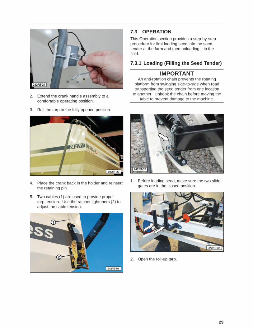
2. Extend the crank handle assembly to a comfortable operating position.
3. Roll the tarp to the fully opened position.
4. Place the crank back in the holder and reinsert the retaining pin.
5. Two cables (1) are used to provide proper tarp tension. Use the ratchet tighteners (2) to adjust the cable tension.
7.3 OPERATIONThis Operation section provides a step-by-step procedure for first loading seed into the seed tender at the farm and then unloading it in the field.
7.3.1 Loading (Filling the Seed Tender)
IMPORTANTAn anti-rotation chain prevents the rotating
platform from swinging side-to-side when road transporting the seed tender from one location
to another. Unhook the chain before moving the table to prevent damage to the machine.
1. Before loading seed, make sure the two slide gates are in the closed position.
2. Open the roll-up tarp.
30
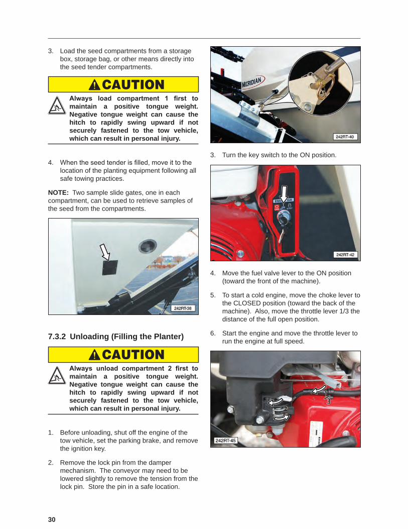
3. Load the seed compartments from a storage box, storage bag, or other means directly into the seed tender compartments.
CAUTION Always load compartment 1 first to maintain a positive tongue weight. Negative tongue weight can cause the hitch to rapidly swing upward if not securely fastened to the tow vehicle, which can result in personal injury.
4. When the seed tender is filled, move it to the location of the planting equipment following all safe towing practices.
NOTE: Two sample slide gates, one in each compartment, can be used to retrieve samples of the seed from the compartments.
7.3.2 Unloading (Filling the Planter)
CAUTION Always unload compartment 2 first to maintain a positive tongue weight. Negative tongue weight can cause the hitch to rapidly swing upward if not securely fastened to the tow vehicle, which can result in personal injury.
1. Before unloading, shut off the engine of the tow vehicle, set the parking brake, and remove the ignition key.
2. Remove the lock pin from the damper mechanism. The conveyor may need to be lowered slightly to remove the tension from the lock pin. Store the pin in a safe location.
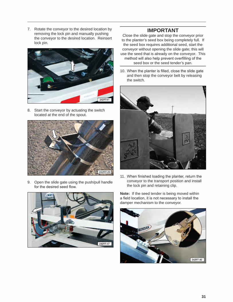
3. Turn the key switch to the ON position.
4. Move the fuel valve lever to the ON position (toward the front of the machine).
5. To start a cold engine, move the choke lever to the CLOSED position (toward the back of the machine). Also, move the throttle lever 1/3 the distance of the full open position.
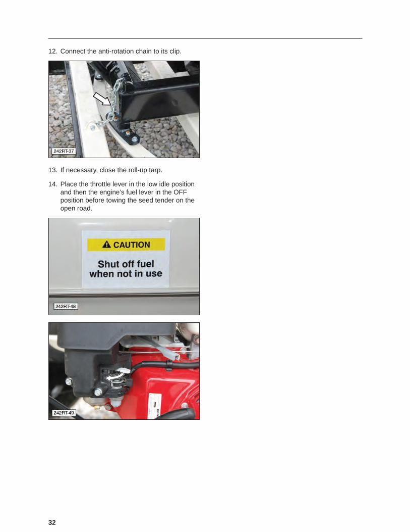
6. Start the engine and move the throttle lever to run the engine at full speed.
31
7. Rotate the conveyor to the desired location by removing the lock pin and manually pushing the conveyor to the desired location. Reinsert lock pin.
8. Start the conveyor by actuating the switch located at the end of the spout.
9. Open the slide gate using the push/pull handle for the desired seed flow.
IMPORTANTClose the slide gate and stop the conveyor prior to the planter’s seed box being completely full. If the seed box requires additional seed, start the conveyor without opening the slide gate; this will
use the seed that is already on the conveyor. This method will also help prevent overfilling of the
seed box or the seed tender’s pan.
10. When the planter is filled, close the slide gate and then stop the conveyor belt by releasing the switch.
11. When finished loading the planter, return the conveyor to the transport position and install the lock pin and retaining clip.
Note: If the seed tender is being moved within a field location, it is not necessary to install the damper mechanism to the conveyor.
32
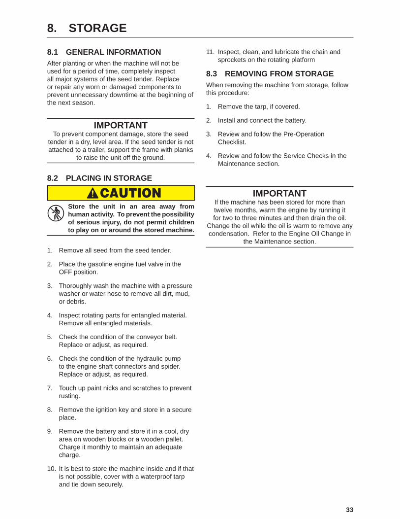
12. Connect the anti-rotation chain to its clip.
13. If necessary, close the roll-up tarp.
14. Place the throttle lever in the low idle position and then the engine’s fuel lever in the OFF position before towing the seed tender on the open road.
33
8. STORAGE
8.1 GENERAL INFORMATIONAfter planting or when the machine will not be used for a period of time, completely inspect all major systems of the seed tender. Replace or repair any worn or damaged components to prevent unnecessary downtime at the beginning of the next season.
IMPORTANTTo prevent component damage, store the seed
tender in a dry, level area. If the seed tender is not attached to a trailer, support the frame with planks
to raise the unit off the ground.
8.2 PLACING IN STORAGE
CAUTION Store the unit in an area away from human activity. To prevent the possibility of serious injury, do not permit children to play on or around the stored machine.
1. Remove all seed from the seed tender.
2. Place the gasoline engine fuel valve in the OFF position.
3. Thoroughly wash the machine with a pressure washer or water hose to remove all dirt, mud, or debris.
4. Inspect rotating parts for entangled material. Remove all entangled materials.
5. Check the condition of the conveyor belt. Replace or adjust, as required.
6. Check the condition of the hydraulic pump to the engine shaft connectors and spider. Replace or adjust, as required.
7. Touch up paint nicks and scratches to prevent rusting.
8. Remove the ignition key and store in a secure place.
9. Remove the battery and store it in a cool, dry area on wooden blocks or a wooden pallet. Charge it monthly to maintain an adequate charge.
10. It is best to store the machine inside and if that is not possible, cover with a waterproof tarp and tie down securely.
11. Inspect, clean, and lubricate the chain and sprockets on the rotating platform
8.3 REMOVING FROM STORAGEWhen removing the machine from storage, follow this procedure:
1. Remove the tarp, if covered.
2. Install and connect the battery.
3. Review and follow the Pre-Operation Checklist.
4. Review and follow the Service Checks in the Maintenance section.
IMPORTANTIf the machine has been stored for more than twelve months, warm the engine by running it for two to three minutes and then drain the oil.
Change the oil while the oil is warm to remove any condensation. Refer to the Engine Oil Change in
the Maintenance section.

34
9. MAINTENANCE
MAINTENANCE SAFETY
• Good maintenance is your responsibility.
• Follow good shop practices.
- Keep service area clean and dry.
- Be sure electrical outlets and tools are properly grounded.
- Use adequate light.
• Make sure there is plenty of ventilation. Never operate the engine in a closed building. Exhaust fumes may cause asphyxiation.
• Before working on this machine, shut OFF the engine, and remove the ignition keys.
• Never work under equipment unless it is securely blocked.
• Always use personal protection devices, such as eye, hand, and hearing protectors when performing any service or maintenance.
• Where replacement parts are necessary for periodic maintenance and servicing, genuine factory replacement parts must be used to restore your equipment to the original specifications. The manufacturer will not be responsible for injuries or damages caused by use of unapproved parts and/or accessories.
• A fire extinguisher and first aid kit should be readily accessible while performing maintenance on this equipment.
• Periodically tighten all bolts, nuts, and screws and check that all cotter pins are properly installed to ensure the unit is in safe operating condition.
• When completing a maintenance or service function, make sure all safety shields and devices are installed before placing the unit in service.
• Disconnect all electronic device cables from the seed tender before performing any arc welding repair. Damage from high currents may cause internal electronic device damage.
9.1 LUBRICATIONUse the Service Checks information in the Maintenance section to keep a record of all scheduled maintenance.
1. Use an SAE multi-purpose high temperature grease or a multi-purpose lithium base grease.
2. Use only a handheld grease gun for all greasing. An air-powered greasing system can damage the seals on the bearings and lead to early failures.
3. Wipe grease fitting with a clean cloth before greasing to avoid injecting dirt and grit.
4. Replace and repair broken fittings immediately.
5. If fittings will not take grease, remove and clean thoroughly. Also, clean lubricant passageway. Replace fitting, if necessary.
9.1.1 Grease Fitting Locations
Each axle is equipped with a grease zerk under the center dust cap of the wheel.

35
10. SERVICE PROCEDURES
10.1 HYDRAULIC SYSTEM10.1.1 Hydraulic Oil Change
An oil and filter change is recommended annually or every 400 hours of operation using an AW HVI Hydraulic ISO 32 oil.
IMPORTANTNever run the hydraulic pump unless the hydraulic
oil tank is full (indicated in sight level gauge).
1. Place a large waste oil container under the inlet hose. The hydraulic tank holds approximately ten gallons of oil.
2. Drain the hydraulic tank by removing the inlet hose from the pump. Allow the tank to drain completely.
3. Remove and replace the oil filter. Apply a thin coat of oil to the rubber seal of the new oil filter. Hand‑tighten only.
4. Reconnect the inlet hose to the pump.
5. Fill the tank to the fill line at the top of the gauge with approximately ten gallons of AW HVI Hydraulic ISO 32 oil. Replace the cap.
6. Start the engine and cycle all the cylinders several times.
7. Recheck the oil level in the tank and add, as needed.
10.1.2 Hydraulic Manifold
IMPORTANTThe manifold contains pressure relief valves
and solenoids which have been factory installed and set up for the most efficient operation of the seed tender. DO NOT adjust these relief valves or replace the solenoid valves. If the unit is not operating properly, refer to the Troubleshooting
section, call an authorized dealer, or call the factory.
10.1.3 Hydraulic Motor Coupling
Changing the pump coupling does not require the hydraulic tank to be drained. If the pump must be disconnected, drain the hydraulic tank and be prepared to catch any oil that remains in the two hydraulic hoses.
1. Remove the orange protective cover from the adapter assembly.
2. Remove the two pump mounting bolts.

36
3. Pull the pump away from the adapter to separate the coupling halves.
4. Loosen the setscrews in each coupling half and remove the old couplings.
5. Install new couplings on the engine shaft and the pump shaft. When completely assembled, the shaft length in each coupling half should be the same. Tighten the pump end setscrews to 78 to 87 lb-in. Do not tighten the engine shaft coupling at this time.
6. Place the urethane spider in the pump coupling. Align and install the pump and pump coupling.
7. Tighten the pump bolts to a “Grade 5” bolt torque for that size of bolt. Refer to the 4.2 Bolt Specifications section.
8. Slide the engine coupling against the other coupling half and tighten the setscrew.
9. Replace the orange protective cover.
NOTE: If the adapter plate was removed, tighten the four retaining bolts to “Grade 5” bolt torque for that size of bolt.
10.2 ENGINEFor any questions concerning the Honda® engine not provided in this manual, refer to the OEM manual that was provided with the seed tender.
To contact Honda®, refer to the OEM Literature section in this manual.
10.2.1 Approved Fuel
Use a regular unleaded automotive gasoline for all operating conditions. The fuel tank capacity is 1.0 liter (2.1 US pints).
10.2.2 Engine Oil
Use a typical SAE 10W-30 or 10W-40 multi-viscosity motor oil for normal operating conditions. Consult your engine manual for the recommended oil in cold temperatures. The crankcase capacity is 1.1 liters (1.16 US qt.).
10.2.3 Change Engine Oil
1. Review the Operator’s Manual for the engine.
2. Allow the engine to cool before changing the oil. Draining works best when the oil is warm.
CAUTION Burn Hazard. Hot engine oil can burn skin.
3. Be sure the engine key switch is in the OFF position and the fuel valve is turned OFF.
4. Place a pan under the drain plug.
5. Remove the drain plug and allow the oil to drain for ten minutes.
6. Reinstall the engine drain plug and tighten.
7. Dispose of the oil in an approved container. Follow industrial disposal regulations.
8. Fill the engine with SAE 10W-30 oil for general usage. If the engine is operated in more extreme conditions, refer to the OEM manual for oil recommendations.
9. Run the engine for one minute and recheck the oil level. Add oil, as needed.
37
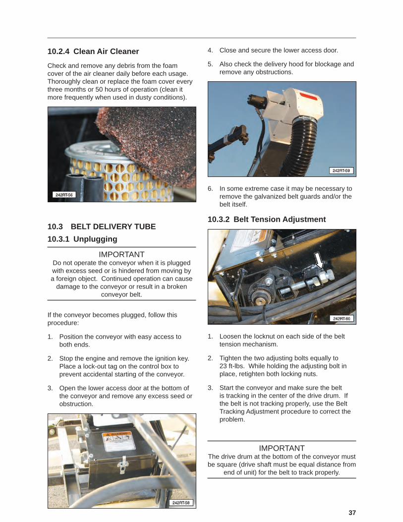
10.2.4 Clean Air Cleaner
Check and remove any debris from the foam cover of the air cleaner daily before each usage. Thoroughly clean or replace the foam cover every three months or 50 hours of operation (clean it more frequently when used in dusty conditions).
10.3 BELT DELIVERY TUBE10.3.1 Unplugging
IMPORTANTDo not operate the conveyor when it is plugged with excess seed or is hindered from moving by a foreign object. Continued operation can cause
damage to the conveyor or result in a broken conveyor belt.
If the conveyor becomes plugged, follow this procedure:
1. Position the conveyor with easy access to both ends.
2. Stop the engine and remove the ignition key. Place a lock-out tag on the control box to prevent accidental starting of the conveyor.
3. Open the lower access door at the bottom of the conveyor and remove any excess seed or obstruction.
4. Close and secure the lower access door.
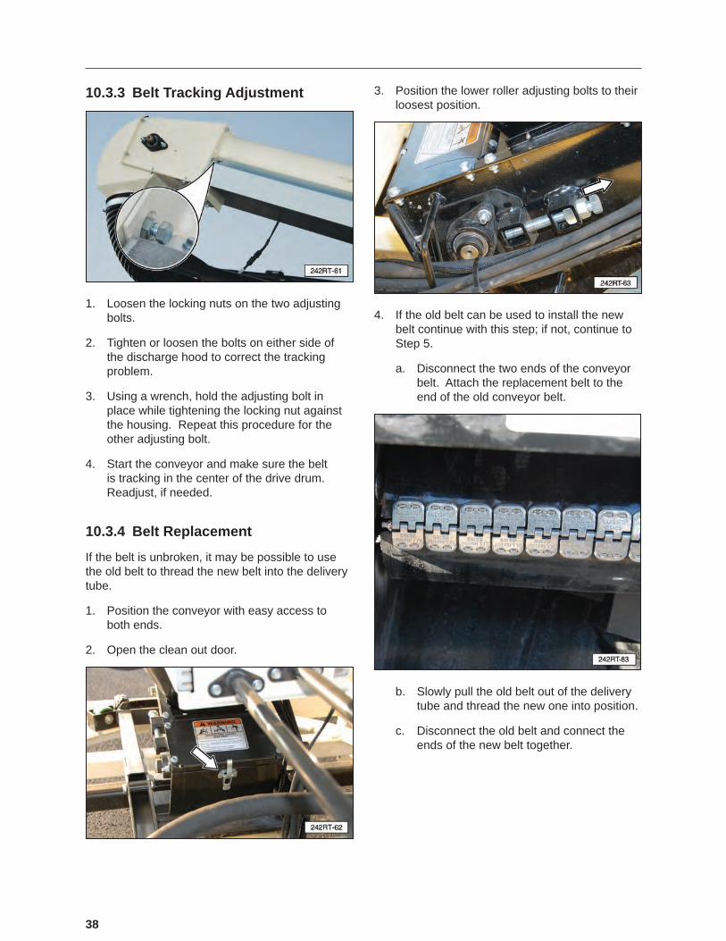
5. Also check the delivery hood for blockage and remove any obstructions.
6. In some extreme case it may be necessary to remove the galvanized belt guards and/or the belt itself.
10.3.2 Belt Tension Adjustment
1. Loosen the locknut on each side of the belt tension mechanism.
2. Tighten the two adjusting bolts equally to 23 ft-lbs. While holding the adjusting bolt in place, retighten both locking nuts.
3. Start the conveyor and make sure the belt is tracking in the center of the drive drum. If the belt is not tracking properly, use the Belt Tracking Adjustment procedure to correct the problem.
IMPORTANTThe drive drum at the bottom of the conveyor must be square (drive shaft must be equal distance from
end of unit) for the belt to track properly.
38
10.3.3 Belt Tracking Adjustment
1. Loosen the locking nuts on the two adjusting bolts.
2. Tighten or loosen the bolts on either side of the discharge hood to correct the tracking problem.
3. Using a wrench, hold the adjusting bolt in place while tightening the locking nut against the housing. Repeat this procedure for the other adjusting bolt.
4. Start the conveyor and make sure the belt is tracking in the center of the drive drum. Readjust, if needed.
10.3.4 Belt Replacement
If the belt is unbroken, it may be possible to use the old belt to thread the new belt into the delivery tube.
1. Position the conveyor with easy access to both ends.
2. Open the clean out door.
3. Position the lower roller adjusting bolts to their loosest position.
4. If the old belt can be used to install the new belt continue with this step; if not, continue to Step 5.
a. Disconnect the two ends of the conveyor belt. Attach the replacement belt to the end of the old conveyor belt.
b. Slowly pull the old belt out of the delivery tube and thread the new one into position.
c. Disconnect the old belt and connect the ends of the new belt together.

39
5. If the old belt cannot be used:
a. Remove the discharge hood and lower the galvanized belt guards.
b. Install the new belt and connect the two ends together.
6. Tighten the two drive drum adjusting bolts equally to 23 ft-lbs. While holding the adjusting bolt in place, retighten both locking nuts.
7. Start the conveyor to make sure the belt is tracking properly. If the belt is not tracking properly, use the Belt Tracking Adjustment procedure to correct the problem.
8. Recheck the tension and alignment of the belt frequently during the first ten hours of operation and adjust, as needed.
NOTE: Then, resume regular maintenance. Typically, a belt will seat itself during the first ten hours of operation and then require less or no adjustment.
10.4 TRAILER BREAK-AWAY SYSTEM
10.4.1 Testing the Battery
1. Disconnect the trailer plug from the tow vehicle; otherwise, you are testing the tow vehicle’s battery.
2. Press the green TEST button on the control box located inside the frame of the trailer. The green indicator light should illuminate if the battery is fully charged. If the yellow or red indicator lights illuminate, the unit’s battery should be charged before towing the trailer.
IMPORTANTIf the battery is weak or dead (red indicator, even after charging), as indicated by the indicator light,
the battery must be replaced.
3. Plug the trailer into the tow vehicle. The yellow “Charging” light should be ON.
4. Test the system by pulling the pin out of the break-away switch. The battery will activate the brakes. (Note: Do not use this kit as a parking brake). The battery should be charged and tested prior to each trailer outing.

40
10.4.2 Changing Battery
The battery in the break-away system is rechargeable, but not replaceable. If the battery will not hold a charge, replace the unit.
10.5 WHEEL BOLT TORQUE REQUIREMENTS
1. Initially check the wheel bolt torque at 10, 25, and 50 miles and after each wheel removal. Refer to the Wheel Bolt Torque Requirements section in this manual for tightening instructions.
NOTE: Torque wrenches are the best method to ensure the proper amount of torque is being applied to a wheel nut.
CAUTION To prevent injury due to possible dangerous separation of wheels from the axle, the wheel nuts must be maintained at the proper torque levels. Properly maintained wheel nuts prevent loose wheels and broken studs.
2. Tighten the wheel nuts in three stages. — First stage: 20 to 25 foot pounds. — Second stage: 50 to 60 foot pounds. — Third stage: 90 to 120 foot pounds.
3. Tighten the wheel nuts in a clockwise, cross-axle alternating pattern.
10.6 FENDER AND AXLE HOLD-DOWN BOLTSCheck the torque on the fender hold-down bolts at least once per year. Tighten the bolts to 40 ft-lbs.
Check torque or axle mounting bolts. Tighten bolts to 290 ft-lbs..
10.7 SERVICE RECORD CHARTThe chart on the following page should be copied and filled out as maintenance is performed on the machine. Refer to the Lubrication, Maintenance, and Service sections for additional instructions.

41
10.7 SERVICE RECORD CHART (CONTINUED)
Date
Serviced by8 hours or daily
Check Engine Fluid LevelsCheck Hydraulic Tank Oil LevelTest Break-Away Brake SystemInspect TiresCheck Remote Control Battery LifeCheck Oil Filter IndicatorCheck Conveyor Belt Tension and Alignment
50 Hours or Weekly
Clean Engine Air Intake FilterCheck Tire PressureCheck Conveyor Belt Tension and AlignmentClean wireless remote control regularly with a damp cloth and mild detergent.
200 Hours or SEMI/ANNUAL
Adjust Brakes
Inspect Brake Magnets
400 hours or annually
Change Engine OilCheck Wheel Bolt TorqueCheck Frame and Trailer Hold-DownsCheck Hydraulic Motor CouplingCheck Turntable Nylon Slide BlocksCheck Load CellsInspect Brake Lining Wear, Brake Cylinder, and Brake WiringGrease Wheel Bearings and Check Hub for WearInspect Axle Grease SealInspect Springs for WearInspect transmitter electrical wiring for wear points or other damage. Repair, as required.Inspect all electrical wiring connections for looseness or corrosion. Tighten and/or seal, as necessary.Thoroughly Clean Machine

42
10.8 SERVICE CHECKS10.8.1 Daily (8 Hours)
1. Check engine oil level and fill, as needed.
WARNING Gasoline is a highly combustible fuel. Improper use, handling, or storage of gasoline can be dangerous. Never touch or fill a hot engine. DO NOT fill the engine’s fuel tank near an open flame while smoking or while engine is running. DO NOT fill tank in an enclosed area with poor ventilation. Wipe up spills immediately.
2. Check engine fuel level and fill, as needed.
3. Check hydraulic fluid level (1) and fill, as needed.
4. Check filter life indicator (2). Change the filter if the indicator needle is in the yellow or red area.
5. Test trailer break-away system. Refer to the section in this manual.
6. Initially check wheel bolt torque at 10, 25, and 50 miles. Refer to Wheel Bolt Torque Requirements section in this manual for tightening instructions.
7. Check wireless remote control battery life and change them, if needed. Refer to the section in this manual for additional information.
8. Check delivery belt for proper tension and tracking. Refer to sections on adjusting the belt in this manual.
10.8.2 Weekly (50 Hours)
1. Change engine oil.
2. Clean or replace the foam filter element. Replace the paper air filter, as required.
3. Check the tension on the delivery belt. Adjust tension if needed. Refer to the section in this manual for instructions.
4. Check the tire pressure. Inflate the tires to the recommended pressure stated on the tire.
10.8.3 Annually (400 Hours)
1. Check wheel bolt torque. Refer to Wheel Bolt Torque Requirements section in this manual for tightening instructions.
2. Check fender hold-down bolts.
3. Check hydraulic motor to engine shaft coupling and spider. Refer to the Changing Hydraulic Motor Coupling section for instructions.
4. Check turntable rollers.
5. Thoroughly clean the seed tender.
6. Check the tires for wear, and replace if needed.

43
10.9 AXLE MAINTENANCE10.9.1 First 200 Miles
1. Adjust brakes. Refer to OEM manual for procedure.
10.9.2 3,000 Miles or 3 Months
1. Adjust brakes. Refer to OEM manual for procedure.
2. Check torque on wheel nuts. Refer to the section in this manual.
3. Inspect tires for wear. Refer to OEM manual for procedure.
10.9.3 6,000 Miles or 6 Months
1. Inspect brake magnets for wear. Refer to OEM manual for procedure.
2. Inspect suspension parts for wear. Refer to OEM manual for procedure.
10.9.4 12,000 Miles or 12 Months
1. Inspect brake lining wear, check brake cylinder for leaks, and inspect brake wiring for damage. Refer to OEM manual for procedure.
2. Grease the wheel bearings and check the hub for wear. Refer to OEM manual for procedure.
3. Inspect grease seal for leakage. Refer to OEM manual for procedure.
4. Inspect springs for any wear or loss of arch. Refer to OEM manual for procedure.
10.10 TIRESCheck the tires for normal and/or abnormal tire wear. Replace tires that are damaged or worn beyond normal tread life. Refer to the axle OEM manual for a Tire Wear Diagnostic Chart.
Replace the tires with Meridian part number 18131 or an equivalent tire:
3T235/80R16 TR643
Load Range E For Trailer Service Only
10.11 WELDING REPAIRS Repair welding must be done with care and with procedures that may be beyond the capabilities of the ordinary welder.
Before performing any type of welding repair to the seed tender, contact Meridian for approval.
WARNINGPersonal Injury Hazard. Repairs or modifications to the trailer, trailer tongue, or trailer hitch can result in
serious injury or death should these repairs fail.
IMPORTANT NOTICEAnyone performing a welding repair should be certified in accordance to the American Welding
Society (AWS) standards.
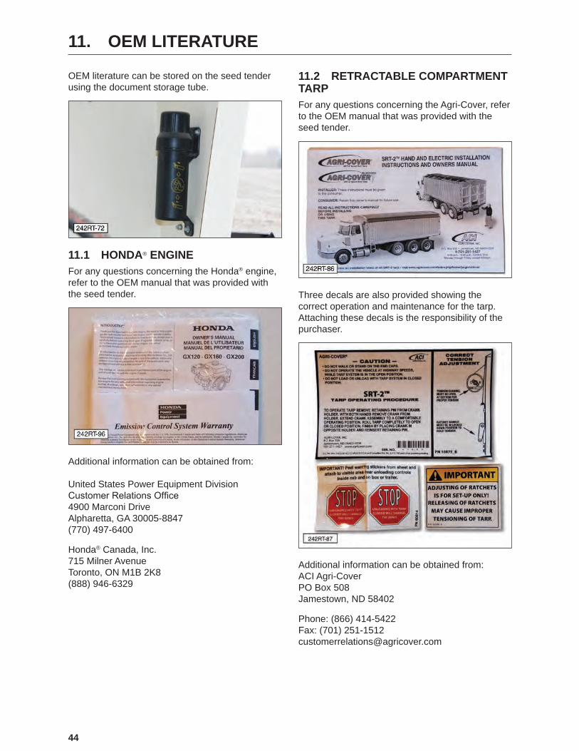
44
11. OEM LITERATURE
OEM literature can be stored on the seed tender using the document storage tube.
11.1 HONDA® ENGINEFor any questions concerning the Honda® engine, refer to the OEM manual that was provided with the seed tender.
Additional information can be obtained from: United States Power Equipment Division Customer Relations Office 4900 Marconi Drive Alpharetta, GA 30005-8847 (770) 497-6400
Honda® Canada, Inc. 715 Milner Avenue Toronto, ON M1B 2K8 (888) 946-6329
11.2 RETRACTABLE COMPARTMENT TARPFor any questions concerning the Agri-Cover, refer to the OEM manual that was provided with the seed tender.
Three decals are also provided showing the correct operation and maintenance for the tarp. Attaching these decals is the responsibility of the purchaser.
Additional information can be obtained from: ACI Agri-Cover PO Box 508 Jamestown, ND 58402
Phone: (866) 414-5422 Fax: (701) 251-1512 [email protected]

45
11.3 AXLEFor any questions concerning the Axis Products axle, refer to the OEM manual that was provided with the seed tender. An Owner’s Manual and parts listing is provided with the seed tender.
Additional information can be obtained from: Axis Products, Inc. 3403 Reedy Drive Elkhart, IN 46514 Phone: (574) 266-8282
46
12. TROUBLESHOOTING
12.1 TROUBLESHOOTING CHART
PROBLEM CAUSE SOLUTIONEngine will not start. No fuel. Fill the fuel tank.
Low engine oil. Fill the crankcase with oil.Cold engine. Open choke.Ignition key switch off. Turn ignition key switch on.Battery dead. Recharge or replace battery.Engine problem. Refer to engine manual.
Conveyor belt will not start. No power. Start engine and increase speed above 1400 RPM.
Drive motor coupling. Repair or replace coupling.Belt tension. Increase belt tension.No hydraulic oil. Check oil level.
Electrical or hydraulic functions are not working properly.
Battery cable or battery. Check battery cable and make sure battery is fully charged.
Hydraulic valve or motor. Ensure hydraulic pump is working properly and hydraulic tank is filled with oil.
Intermittent function. Loose connector at the valve coil.
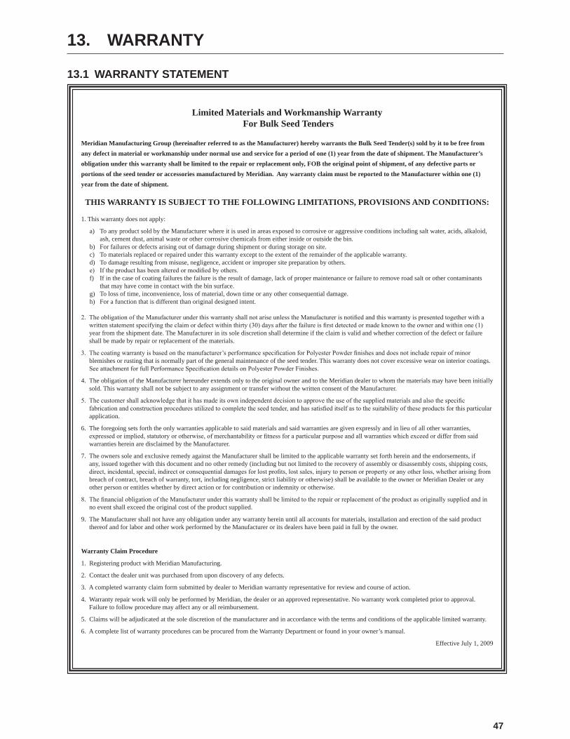
47
13. WARRANTY
13.1 WARRANTY STATEMENT
Limited Materials and Workmanship Warranty
For Bulk Seed Tenders
Meridian Manufacturing Group (hereinafter referred to as the Manufacturer) hereby warrants the Bulk Seed Tender(s) sold by it to be free from any defect in material or workmanship under normal use and service for a period of one (1) year from the date of shipment. The Manufacturer’s obligation under this warranty shall be limited to the repair or replacement only, FOB the original point of shipment, of any defective parts or portions of the seed tender or accessories manufactured by Meridian. Any warranty claim must be reported to the Manufacturer within one (1) year from the date of shipment.
THIS WARRANTY IS SUBJECT TO THE FOLLOWING LIMITATIONS, PROVISIONS AND CONDITIONS:
1. This warranty does not apply:
a) To any product sold by the Manufacturer where it is used in areas exposed to corrosive or aggressive conditions including salt water, acids, alkaloid, ash, cement dust, animal waste or other corrosive chemicals from either inside or outside the bin.
b) For failures or defects arising out of damage during shipment or during storage on site.c) To materials replaced or repaired under this warranty except to the extent of the remainder of the applicable warranty.d) To damage resulting from misuse, negligence, accident or improper site preparation by others.e) Iftheproducthasbeenalteredormodifiedbyothers.f) If in the case of coating failures the failure is the result of damage, lack of proper maintenance or failure to remove road salt or other contaminants
that may have come in contact with the bin surface.g) To loss of time, inconvenience, loss of material, down time or any other consequential damage.h) For a function that is different than original designed intent.
2. TheobligationoftheManufacturerunderthiswarrantyshallnotariseunlesstheManufacturerisnotifiedandthiswarrantyispresentedtogetherwithawrittenstatementspecifyingtheclaimordefectwithinthirty(30)daysafterthefailureisfirstdetectedormadeknowntotheownerandwithinone(1)year from the shipment date. The Manufacturer in its sole discretion shall determine if the claim is valid and whether correction of the defect or failure shall be made by repair or replacement of the materials.
3. Thecoatingwarrantyisbasedonthemanufacturer’sperformancespecificationforPolyesterPowderfinishesanddoesnotincluderepairofminorblemishes or rusting that is normally part of the general maintenance of the seed tender. This warranty does not cover excessive wear on interior coatings. SeeattachmentforfullPerformanceSpecificationdetailsonPolyesterPowderFinishes.
4. The obligation of the Manufacturer hereunder extends only to the original owner and to the Meridian dealer to whom the materials may have been initially sold. This warranty shall not be subject to any assignment or transfer without the written consent of the Manufacturer.
5. Thecustomershallacknowledgethatithasmadeitsownindependentdecisiontoapprovetheuseofthesuppliedmaterialsandalsothespecificfabricationandconstructionproceduresutilizedtocompletetheseedtender,andhassatisfieditselfastothesuitabilityoftheseproductsforthisparticularapplication.
6. The foregoing sets forth the only warranties applicable to said materials and said warranties are given expressly and in lieu of all other warranties, expressedorimplied,statutoryorotherwise,ofmerchantabilityorfitnessforaparticularpurposeandallwarrantieswhichexceedordifferfromsaidwarranties herein are disclaimed by the Manufacturer.
7. The owners sole and exclusive remedy against the Manufacturer shall be limited to the applicable warranty set forth herein and the endorsements, if any, issued together with this document and no other remedy (including but not limited to the recovery of assembly or disassembly costs, shipping costs, direct,incidental,special,indirectorconsequentialdamagesforlostprofits,lostsales,injurytopersonorpropertyoranyotherloss,whetherarisingfrombreach of contract, breach of warranty, tort, including negligence, strict liability or otherwise) shall be available to the owner or Meridian Dealer or any other person or entitles whether by direct action or for contribution or indemnity or otherwise.
8. ThefinancialobligationoftheManufacturerunderthiswarrantyshallbelimitedtotherepairorreplacementoftheproductasoriginallysuppliedandinno event shall exceed the original cost of the product supplied.
9. The Manufacturer shall not have any obligation under any warranty herein until all accounts for materials, installation and erection of the said product thereof and for labor and other work performed by the Manufacturer or its dealers have been paid in full by the owner.
Warranty Claim Procedure
1. Registering product with Meridian Manufacturing.
2. Contact the dealer unit was purchased from upon discovery of any defects.
3. A completed warranty claim form submitted by dealer to Meridian warranty representative for review and course of action.
4. Warranty repair work will only be performed by Meridian, the dealer or an approved representative. No warranty work completed prior to approval. Failure to follow procedure may affect any or all reimbursement.
5. Claims will be adjudicated at the sole discretion of the manufacturer and in accordance with the terms and conditions of the applicable limited warranty.
6. A complete list of warranty procedures can be procured from the Warranty Department or found in your owner’s manual.
Effective July 1, 2009

48
14. PARTS
The following pages contain a list of serviceable parts for the 242RT Seed Express unit.
Parts are available from your authorized Dealer Parts Department.

49
14.1 242RT SEED TENDER TARP KIT AND VIEW WINDOW
242RT-88
1
1
2
3
4
5
6
7
8
9
10
11
1 1 19984 Tarp Kit
2 4 47008 View Glass, S.S. Ring Assm.
3 2 36150 Sample Gate
4 12 19129 Rivet, 3/16” x 1/2”
5 1 19944 Decal, Warranty Notice
6 1 19984 Decal, Serial Number
7 1 18120 Stroke, 5K, 15”, Top Wind Jack
8 1 19541 Bolt, Hex, 3/8-16 x 3/4”, Stainless Steel
9 5 19347 Locknut, Nylon, 3/8”-16
10 2 19568 Bolt, Hex, Flanged, 5/16-18 x 3/4”
11 5 19318 Nut, Hex, Flanged, 5/16-18
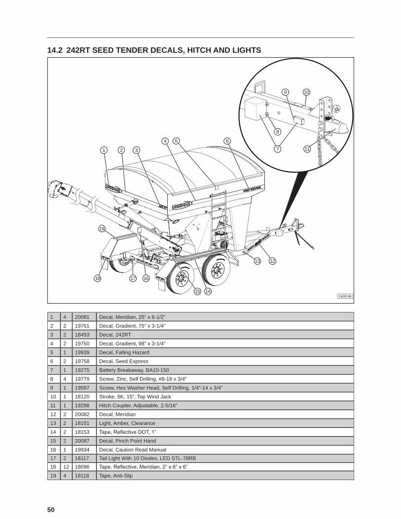
50
14.2 242RT SEED TENDER DECALS, HITCH AND LIGHTS
242RT-89
19
1 2 3
4 5 6
1213
1415
161718
8
7 11
109
1 4 20081 Decal, Meridian, 25” x 6-1/2”
2 2 19751 Decal, Gradient, 75” x 3-1/4”
3 2 18453 Decal, 242RT
4 2 19750 Decal, Gradient, 98” x 3-1/4”
5 1 19939 Decal, Falling Hazard
6 2 19758 Decal, Seed Express
7 1 19275 Battery Breakaway, BA10-150
8 4 19779 Screw, Zinc, Self Drilling, #8-18 x 3/4”
9 1 19597 Screw, Hex Washer Head, Self Drilling, 1/4”-14 x 3/4”
10 1 18120 Stroke, 5K, 15”, Top Wind Jack
11 1 19298 Hitch Coupler, Adjustable, 2-5/16”
12 2 20082 Decal, Meridian
13 2 18151 Light, Amber, Clearance
14 2 18153 Tape, Reflective DOT, 1”
15 2 20087 Decal, Pinch Point Hand
16 1 19934 Decal, Caution Read Manual17 2 18117 Tail Light With 10 Diodes, LED STL-78RB18 12 18096 Tape, Reflective, Meridian, 2” x 6” x 6”
19 4 18118 Tape, Anti-Slip

51
NOTES
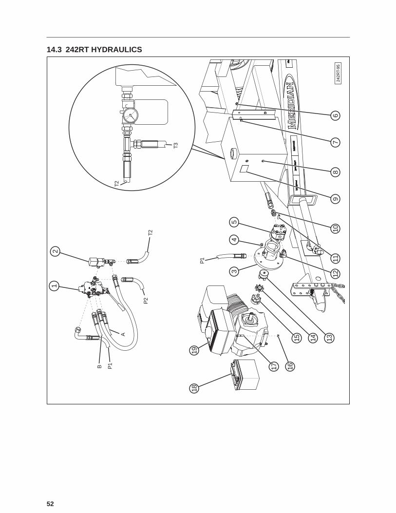
52
14.3 242RT HYDRAULICS
242R
T-95
1819
12
3
17 1615 14 13
1211
109
87
6
45
P1B
A
P2
T2
T2
T3
P1

53
1 1 18293 Monoblock Valve Section (VDM6-4-YE-HP-2500)
2 1 18295 Solenoid, On/Off with Block (CPN-8)
3 1 19289 Adapter, Hyd Tee 3/4”-16 Female SAE 37 Deg Bulkhead, 3/4”-16 Male SAE 37 Deg 3/4”-16 Male SAE 37 Deg
4 4 19569 Bolt, Hex, Flanged, 3/8-16 x 1”
5 1 19295 Pump, Hydraulic
6 9 19564 Nut, Hex, Flanged, 3/8-16
7 4 19325 Bolt, Hex, 3/8-16 x 1”
8 1 19294 Oil Tank, 10 Gallon - Hydraulic Package
9 1 20088 Decal, Warning Hot Surface
10 1 18285 Adapter, Hyd 1-1/16”-12 Male SAE O-Ring Boss to 1-1/16”-12 Male SAE 37 Deg
11 2 18577 Hex Socket Head Cap Screw
12 1 18292 Adapter, Hyd Elbow 7/8”-14 Male SAE O-Ring Boss (Long) to 7/8”-14 Male SAE 37 Deg
13 1 19248 Coupling, Pump with 5/8 x 5/32” Keyway
14 1 19290 Spider, Coupling
15 1 19247 Coupling, Engine with 3/16 x 3/32” Keyway
16 6 19347 Locknut, Nylon, 3/8”-16
17 4 19328 Bolt, Hex, 3/8-16 x 2
18 1 21286-00 Battery, SP-30
19 1 21270 Honda GX340

54
14.4 242RT CONVEYOR SWIVEL, FENDER, AND AXLE
242RT-90
20
19
18
17
16
15
14
13
35
34
33
32
28
29
27
2623 22
2524
3031
12 11 10 9
8
7
6
5
4
3
2
1
A B21

55
1 6 19347 Locknut, Nylon, 3/8-16
2 1 29869 Collar
3 1 19243 Bolt, Hex, 3/8-16 x 2”, Grade 8
4 1 19405 Bushing
5 3 19794 Lynch Pin, 3/16 x 1”
6 3 19774 Pin, Clevis, 1” x 5-45/64” Effective Length
7 1 29875 Wear Disc
8 3 19774 Pin, Clevis, 1” x 5-45/64” Effective Length
9 1 31507 Turret Assembly 2011, Manual
10 1 19326 Bolt, Hex, 3/8-16 x 1-1/4” Steel, Mild
11 1 19564 Nut, Hex, Flanged, 3/8-16
12 1 19255 16” of 1/4” Chain
13 3 19794 Lynch Pin, 3/16 x 1”
14 3 18451 Wheel Axle, 1/2” Dia x 3-3/8”, Greased
15 3 18448 Roller, Polyurethane, 3-1/4” x 2”
16 3 19595 Nut, Hex, Flanged, 1/2-13
17 1 19150 Lift Cylinder
18 2 19785 Cotter Pin, Lock, Ringed, 0.080” for 3/4” Shaft
19 1 19776 Clevis Pin, 3/4” x 2-33/64” Effective Length
20 1 19777 Clevis Pin, 3/4” x 3-49/64” Effective Length
21 1 20526 Tube Extension
22 4 18131 Tire, ST235/80R16
23 2 18678 Axle, 7000 Lbs (2012 Tender Models)
24 8 19394 Nut, Hex, Steel, Mild, 3/4-10
25 8 19396 Washer, Spring Lock, Helical Steel, Mild, 3/4
26 8 18097 Washer, Narrow, Type A Steel, Mild, 3/4
27 3 19388 Bolt, Hex, 3/4-10 x 2”
28 8 19110 Nut, Hex, Flanged, Steel, Mild, Serrated 3/8-16
29 8 19112 Nut, Hex, Nylon, #8-32
30 8 19629 Washer, Flat, 5/32”
31 8 19141 Screw, Round Head, Pan, #8-32 x 5/8
32 2 19274 Mud Flap
33 4 18248 Tube Plug, 4” x 2”
34 2 31509 Fender Bolt On Tandem
35 4 18427 U Bolt, 4” x 2” x 3/8”
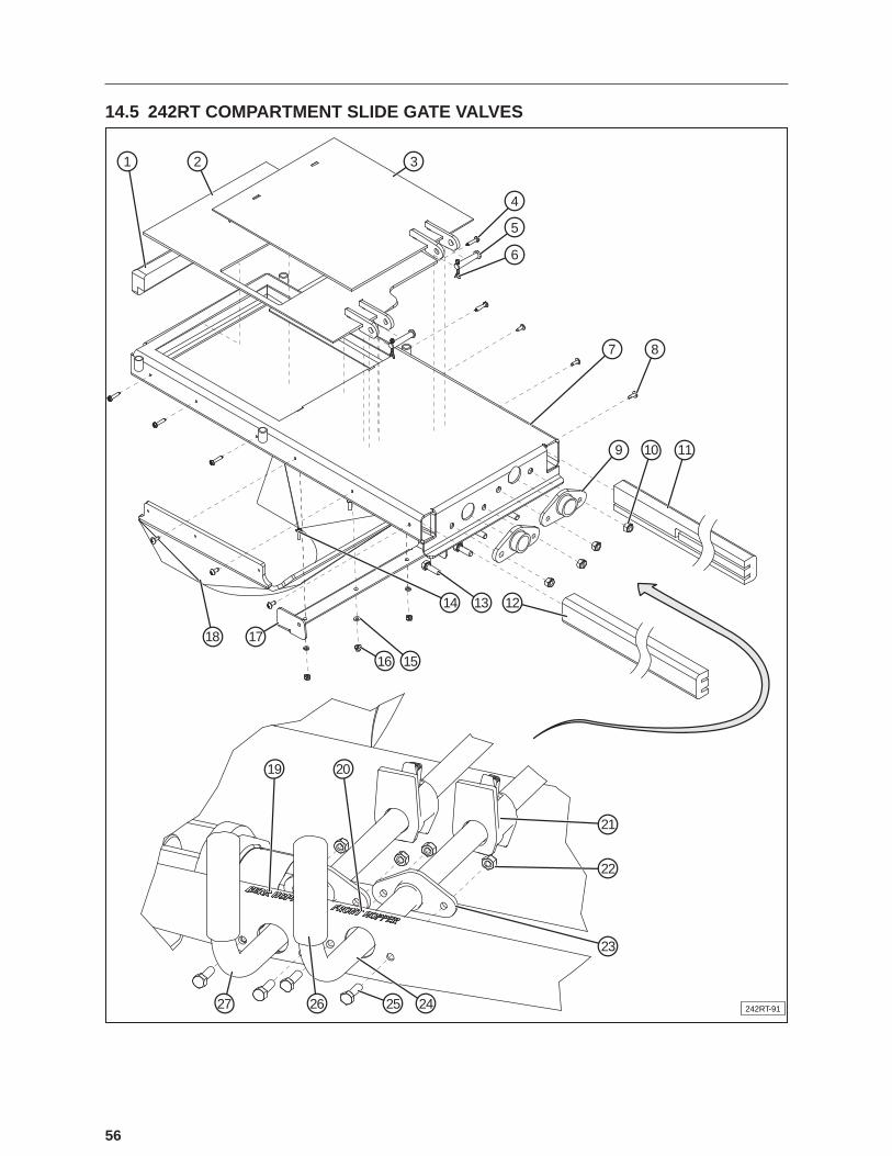
56
14.5 242RT COMPARTMENT SLIDE GATE VALVES
242RT-91
2 3
4
5
6
7 8
9 10 11
121314
15
19 20
21
22
23
24252627
16
1718
1

57
1 1 23606-00 UHMW Gate Guide (End)
2 1 26336 Weldment, Bottom Gate
3 1 26337 Weldment, Top Gate
4 15 19779 Screw, Self Drilling, Zinc, #8-18 x 3/4”
5 2 18361 Clevis Pin, 3/8” x 1-3/4” (1-33/64” Effective Length)
6 2 19795 Pin, Cotter, Extended Prong Square Cut Type, 1/8” x 1”
7 1 26334 Weldment, Gate Housing
8 6 19699 Screw, Self Drilling, No. 8 - 32 x 1/2”
9 2 19404 Bushing, Nylon, 1”
10 8 19586 Locknut, Nylon, 5/16-18
11 1 26341 UHMW Gate Guide (Left)
12 1 26340 UHMW Gate Guide (Right)
13 4 19310 Bolt, Hex, 5/16-18 x 1” Steel, Mild
14 8 19141 Screw, Round Head Pan, #8-32 x 5/8”
15 8 19629 Washer, Flat, 5/32”
16 8 19112 Nut, Hex, Nylon, #8-32
17 1 25332 Retainer, Gate Boot Skirt
18 1 23725-01 Gate Boot Skirt
19 1 26085-00 Decal, Rear Hopper
20 1 26084-00 Decal, Front Hopper
21 2 17996 Assembly, Tail Stop
22 8 19586 Locknut, Nylon, 5/16”-18
23 2 19404 Bushing, Nylon, 1”
24 1 26343 Handle, Slide Gate, Right
25 4 19310 Bolt, Hex, 5/16-18 x 1 Steel, Mild
26 2 19447 Handle Grip
27 1 26342 Handle, Slide Gate, Left

58
14.6 242RT CONVEYOR - LOWER END
242R
T-92
2627
1
23
7
9
8
45
6
11 12 13
1428
15
1617
1819
20
2122232425
10
P3 T4
T3P
2

59
1 1 29393 Conveyor Boot, 6”
2 1 27051-00 Brush
3 1 27009-00 Clamp, Brush Holder
4 1 23336-00 Plate, Left Cap
5 1 23337-00 Plate, Right Cap
6 1 23338-00 Plate, End Skirt Retain
7 1 23324-00 Assembly, Conveyor Pan
8 1 18294 Valve, Flow Control
9 1 26420 Plate, Spacer Flow Control 242
10 1 29401 Plate, Left Side Skirt Retain
11 2 19560 Bolt, Hex, 1/4-20 x 3/4”
12 12 19128 Nut, Hex, Nylon, 1/4-20
13 9 19564 Nut, Hex, Flanged, 3/8-16
14 2 21258-00 Bearing
15 2 27040-00 Housing, Roller Bearing
16 2 23687-00 Weldment, Roller Slide Plate
17 2 23341-00 Plate, Roller Cover
18 4 19335 Bolt, Carriage, 3/8”-16 x 1-1/2”
19 2 23341-00 Plate, Roller Cover
20 2 23687-00 Weldment, Roller Slide Plate
21 2 19380 Bolt, Hex, 5/8”-11 x 4-1/2”
22 2 19663 Nut, Square, 5/8-11
23 2 19382 Nut, Hex, 5/8-11
24 1 36201-02 Assembly, Idler Roller
25 1 29400 Plate, Skirt Retain, Right Side
26 1 23335-00 Plate, Brush Holder
27 1 19560 Bolt, Hex, 1/4-20 x 3/4”
28 2 212588-00 C Collar, Bearing
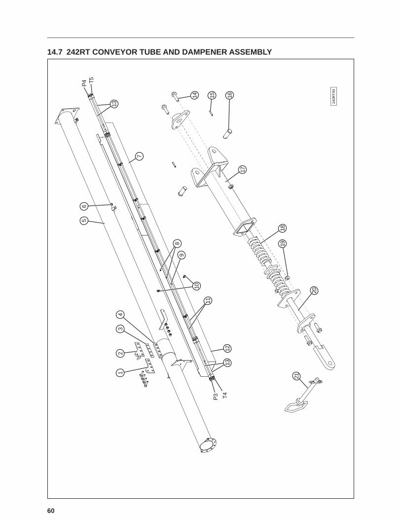
60
14.7 242RT CONVEYOR TUBE AND DAMPENER ASSEMBLY
242R
T-93
12
34
56
7
13
89
10
11
12
14 15 16
17
1819
20
21
13
P3 T4
P4 T5

61
1 1 29376 Plate, Dampener Pin
2 1 29377 Plate, Dampener Pin Rest
3 1 29378 Spacer
4 1 18760 Clamp Compression, 6”
5 1 23331-00 Assembly, Conveyor Tube
6 4 19577 Bolt, Hex, Flanged, 3/8-16 x 3/4”
7 1 25862 Galvanized Belt Guard (Top Section)
8 2 19126 Nut, Hex, Flanged, 1/4-20
9 2 19560 Bolt, Hex, 1/4-20 x 3/4”
10 12 18679 Clamp, Cushioned (1/2”)
11 2 18363 Assembly, Hydraulic SS Tube, 6” Conveyor
12 1 25489 Belt Guard, Galvanized
13 4 32319 Hose Hydraulic Motor to Steel Line, 1/2”
14 4 19581 Bolt, Hex, Flanged, 5/16-18 x 1”
15 2 19237 Pin, Spring
16 2 19070 Pin, 1/2” x 1-1/4”
17 1 23673-00 Assembly, Body
18 1 19744 Spring, Compression
19 5 19318 Nut, Hex, Flanged, 5/16-18
20 1 23662-00 Assembly, Rod
21 1 19748 Pin, Hitch, 1/2” x 4” Effective Length
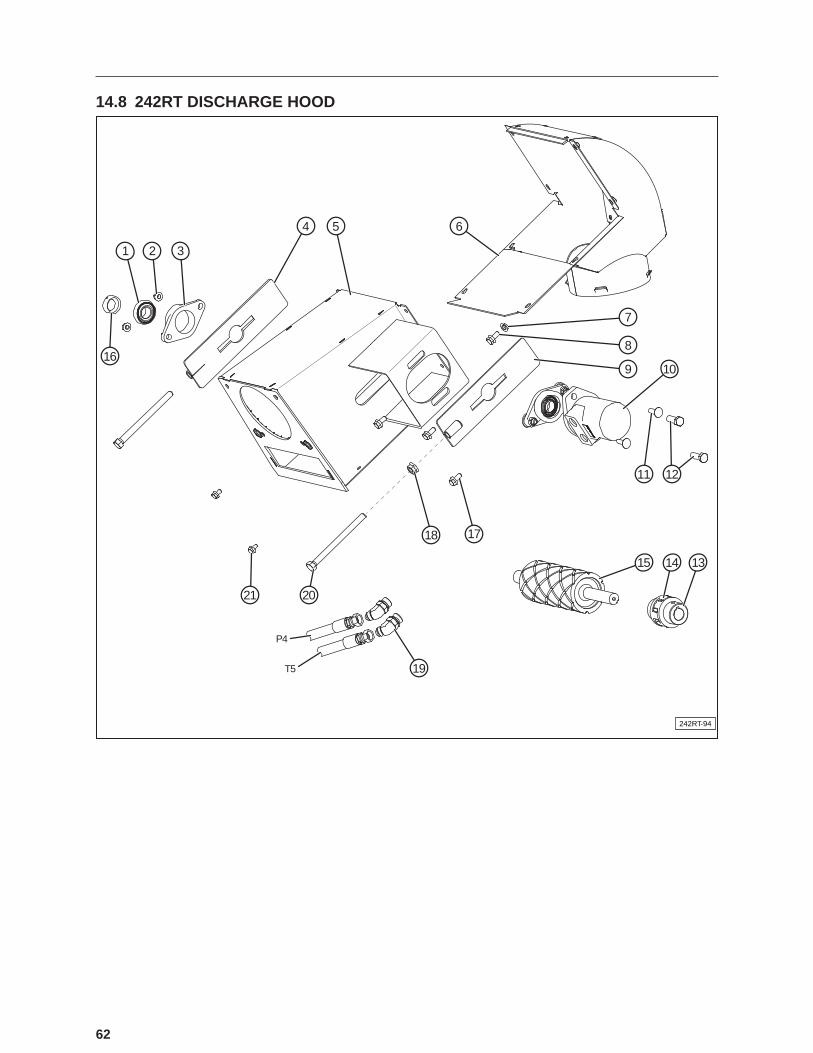
62
14.8 242RT DISCHARGE HOOD
242RT-94
1
16
2 3
4 5 6
7
8
9 10
11 12
15
19
2021
1718
14 13
P4
T5

63
1 1 21258-00 Bearing
2 4 19564 Nut, Hex, Flanged, 3/8-16
3 2 27040-00 Housing, Roller Bearing
4 2 36217-00 Weldment, Belt Tightener Plate
5 1 23339-00 Weldment, Discharge Hood
6 1 36211-00 Weldment, Discharge Transition
7 8 19318 Nut, Hex, Flanged, 5/16-18
8 8 19772 Screw, Hex, Cap, Flanged, 5/16”-18 x 1/2”
9 2 36217-00 Weldment, Belt Tightener Plate
10 1 19769 Hydraulic Motor, 2.8 Cubic Inches
11 4 19695 Bolt, Carriage, 3/8”-16 x 1-1/4”
12 2 19355 Screw, Hex, Cap, 1/2”-13 x 1-1/2
13 2 19249 Coupler, Lovejoy
14 1 19291 Red Coupling Spider
15 1 36200-01 Assembly, Drive Roller
16 1 21258-00C Collar, Bearing
17 4 19577 Bolt, Hex, Flanged, 3/8-16 x 3/4”
18 4 19595 Nut, Hex, Flanged, 1/2-13
19 2 17999 Adapter, Hydraulic, 45 Deg 7/8-14 SAE O-Ring Boss to 3/4”-16 SAE 37 Deg
20 2 18960 Bolt, Hex, Steel, Mild, Full Thread, 1/2-13 x 6.5
21 8 19772 Screw, Hex, Cap, Flanged, 5/16”-18 x 1/2”

64
NOTES

65
NOTES

66
NOTES


68
Box 760, 275 Hespler Ave.Winkler, MB R6W 4A8PH: 204.325.7883TF: 800.665.7259FX: 204.325.5556
2902 Expansion Blvd.Storm Lake, IA 50588PH: 712.732.1780TF: 800.437.2334FX: 712.732.1028
3125 - 24 Ave. N.Lethbridge, AB T1H 5G2PH: 403.320.7070TF: 800.661.1436FX: 403.320.7579
4232 - 38 St.Camrose, AB T4V 4B2PH: 780.672.4516TF: 800.830.2467FX: 780.672.4759
© 2013 Meridian Manufacturing Group. Registered Trademarks Used Under License. Printed In US (01/2012)Printed in US (2/2013) Form No. XXXXX