Embed Size (px)
Citation preview

2015 AUVSI Student UAS Competition Kansas State University, Team SPYKAT
Competition Team Members Collin Pierce, Matt Don, Sydney Schinstock, Alex Lesperance, Steven Blits, Kyle Coates, Caleb Fleming, Ethan Koch, Brad Worsham, Nathan Jones , Chris Piggott, Tony Rodriguez, Brandon Reigel, Florian Browne, Shannon Barry, Aaron Hoffman, K. C. Roberts, Prashanth Ramaswamy, Justin Keller Faculty Advisors Dr. Thompson & Dr. Schinstock Proof of Flight Statement: We certify that the aircraft described in this paper has flown and is fully operational. The U.S. Forest Service has requested intelligence, surveillance, and reconnaissance (ISR) support using unmanned aircraft systems (UAS). In order to meet these needs, Team SpyKat has used a system engineering approach to develop a fully autonomous aircraft equipped with payloads capable of retrieving high quality imaging as well as retrieving information via ground sensors. The system is a modified Sig Kadet Senior aircraft equipped with an ArduPilotPixhawk autopilot and a Canon EOS M Mirrorless digital camera. Imagery is first captured on the onboard Raspberry Pi computer and then transmitted over a 5.0 GHz wireless bridge to the ground station computer that runs Team SpyKat’s custom target detection software. The Raspberry Pi triggers the capture of images with a timer to ensure full coverage of the surveyed area. The autopilot communicates over the 900 MHz band for telemetry and the 2.4 GHz band for backup RC pilot controls. The Simulated Remote Intelligence Center (SRIC) will be connected through a 2.4 GHz data connection. Subsystem tests and full system flight tests have been performed to verify and enhance the completion of objectives as well as all safety standards.
Kansas State University

Contents 1. Introduction to Team SpyKat 2. Systems Engineering Approach
2.1. Mission Requirement Analysis 2.2. Design Rationale and Component Selection
2.2.1. Airframe 2.2.2. Autopilot System 2.2.3. Payload System
2.3. Expected Mission Performance 2.4. Risk Management and Mitigation
3. Team SpyKat Design Descriptions 3.1. Air Vehicle
3.1.1. Gimbal 3.1.2. Egg Drop
3.2. Autopilot 3.2.1. Interoperability 3.2.2. Sense, Detect, and Avoid 3.2.3. Ground Control Station
3.3. Datalinks 3.4. Data Flow 3.5. Flight Path 3.6. Camera 3.7. Image Processing
3.7.1. Target Recognition Application 3.7.2. Target Detection and Analysis 3.7.3. QRC
3.8. Ground Station 4. Testing and Evaluation Results
4.1. Mission Operations 4.2. Mission Task Performance 4.3. Payload System Performance 4.4. Guidance System Performance
5. Safety Considerations 6. Appendix
Kansas State University Team SpyKat 1

1. Introduction to Team SpyKat Team SpyKat consists of students from the Kansas State University American Institute of Aeronautics and Astronautics (AIAA) chapter. Based out of the Mechanical Nuclear Engineering Department, the team has students from Mechanical Engineering, Electrical Engineering, Computer Engineering, and Computer Science. The diversity of its members have contributed to its success in the system engineering required of our unmanned aerial system (UAS). Dr. Dale Schinstock and Dr. J. Garth Thompson are the faculty advisors for the team, and Dr. Schinstock also serves as are RC safety pilot. Collin Pierce, a mechanical engineering major, is the team leader/flight director and has served as the system engineering coordinator.
2. Systems Engineering Approach A systems engineering approach is required for this competition due to its complex, interdisciplinary nature. The system requirements for the competition mission are derived from the 2015 Rules for AUVSI Seafarer Chapter 13th Annual Student UAS (SUAS) Competition document, specifically the system requirements, mission requirements, and task descriptions found in sections 5, 6, and 7. Prior to beginning design work on the project, the team first had to interpret, analyze, and prioritize the mission tasks. While the primary objectives were the focus of our analysis and design rationale, the secondary objectives were analyzed as well.
2.1. Mission Requirement Analysis The goal of the mission is to provide a completely autonomous system to provide intelligence, surveillance, and reconnaissance which take the form of the two primary tasks: autonomous flight and navigation and the search area task. The first primary task is autonomous flight and navigation which has four parameters: take off, flight, waypoint navigation, and landing. The search area task consists of the localization and classification of each target as well as the autonomous search. The primary task parameters must be completed at the threshold level in order to allow for the possibility of completing secondary tasks for additional points; however, the objective level for each parameter is desired. Team SpyKat has planned to complete at least threshold levels of all primary performance parameters. This will allow for attempts at eight of the secondary tasks. The team has planned to complete the following secondary tasks to at least the threshold level: ADLC, Actionable Intelligence, OffAxis Target, Emergent Target, SRIC, Air Drop, Interoperability, and Sense, Detect and Avoid.
2.2. Design Rationale and Component Selection After analyzing the mission requirements, the team had to identify the basic subsystems and the components that would be required by the mission. The following sections will introduce the team’s initial component selection and rationale; full system descriptions can be found in section 4 of this document.
Kansas State University Team SpyKat 2
2.2.1. Airframe The Airframe SubTeam handles all of the physical aspects of the crew, including construction and maintenance of the air vehicle as well as design and fabrication of payload components inside of the frame.
The air vehicle used by the team is a modified Sig Kadet Senior. Modifications to the original Sig Kadet include a widening of the fuselage and material upgrade to full carbon fiber sandwich panels. Our reasons for modifying the kit airframe include increased space requirements for internal payload devices and a need for a more robust, versatile, and durable frame.
The motor, a Hacker C5010L ACRO +6.7:1, was chosen because it, along with the 16x13” AeroNaut CAMCarb. props, has been well tested to produce the desired amount of thrust required for both takeoff and steady level flight without unnecessarily draining the battery.
The wing is a standard Sig Kadet Senior kit wing, which is assembled from two pieces and attached to the airframe at the flightline. This wing was chosen for its dependability in numerous, ease of construction, and replaceability.
The landing gear consists of two symmetrical carbon fiber skids that run along the sides of the air vehicle. The skids were designed to allow for a large tolerance between the bottom of the airframe and gimbaled camera and the many ground conditions possible (high grass, unlevel terrain, presence of rocks, etc). The all carbon fiber construction was chosen to increase the durability of the landing gear and safeguard every air system landing.
This year, Team SpyKat has been successful in designing, producing, and testing a two axis gimbal. This gimbal will be carrying the Image Analysis SubTeam’s Canon EOS M camera. It is constructed out of 3D printed ABS plastic, which was determined to have a high durability and extreme ease of construction.
In order to complete the Egg Drop Task team SpyKat designed and printed an Egg Drop Device. This device was designed in order to repeatedly deliver a quick, straight, and minimally resistant free fall upon command. The design includes three components; an egg holder, a servo, and an egg drop arm. The streamer required on the top of the egg will be rolled and placed directly above the egg inside of the dropping device to allow for consistent snagfree drops. Three separate test drops have verified that drops are snagfree.
2.2.2. Autopilot System Early selection of the flight controller was the team’s first priority due to the dependence of all subsystems on the flight control unit. The team investigated the use of three different flight controllers. The previous year’s autopilot: the APM 2.6 board with ArduPilot firmware, and two others: the Pixhawk board with Ardupilot firmware, and the Pixhawk board with its native PX4 firmware are compared in Table 1. All three systems contain open source firmware, giving the team the ability to modify both the autopilot and ground station source code. This ability is essential, it allows the team to meet mission requirements not supported by the source code of the flight controllers. As the flight controller code has become more advanced and developed, and the team added more and more capabilities, the need for a better processing capacity and more onboard memory became evident. This factor eliminated the team’s previous autopilot, the APM 2.6 board, since its processing capacity and memory are much less than that of the Pixhawk board (see Table 1). This decision left the Pixhawk board as the only hardware choice. The two firmwares available for the Pixhawk, PX4 and Ardupilot are quite similar in nature. Both communicate with their respective Ground Control Station (GCS) over the open source MAVLink protocol and both are capable of controlled flight for a plane. However, the team decided to use the Ardupilot firmware since it and its GCS, Mission Planner (MP), are more widely used, and therefore
Kansas State University Team SpyKat 3

more widely developed and supported than the PX4 firmware. Additionally, the team is already more familiar with the Ardupilot firmware as it is very similar to the Ardupilot firmware as on the APM 2.6.
Board APM 2.6 Pixhawk
Firmware Ardupilot Ardupilot PX4
System Cost $159.99 $249.99 $249.99
Processor 8bit Atmel ATMEGA2560 32bit ARM Cortex M4 32bit ARM Cortex M4
Flash Memory 256 KB 2 MB 2 MB
Support/Development Good Excellent Fair
Configurability Excellent Excellent Good
Ease of Modification Excellent Excellent Excellent
Safety Good Good Good
Table 1: Flight Controller Comparison
2.2.3. Payload System Team SpyKat has developed and thoroughly tested its system in order to meet the requirements set by the competition. Components were selected for their compatibility with with one another. The onboard payload currently consists of a gimbaled Canon EOS M Mirrorless camera, a Raspberry Pi, an eye fi card, a network switch, an egg drop mechanism, and wireless communication bullets. This payload provides targetable high resolution imagery, a mechanism for dropping a payload, and wireless communication capabilities. Information is transmitted through Ubiquity bullets to two ground station computers: one dedicated to image analysis software, and one controlling the autopilot, as well as the Sense, Detect, and Avoid mitigation logic.
2.3. Expected Mission Performance
As of May 20, 2015, the 2015 Team SpyKat system and operating personnel have conducted 20 flight tests over the span of nine months in addition to a great deal of subsystem and ground tests. Test results and evaluation can be found in section 4 for additional details of our expected mission performance. Due to the large number of tasks, the team decided that it would not be possible to all secondary tasks within the time requirements. A tradeoff analysis was performed in order to determine which tasks to attempt. Due to the higher weighting of the primary tasks on the total mission performance, all primary tasks will be attempted with the goal of reaching the objective for each task. The time to complete the primary tasks is estimated to be 15 minutes. Without knowing exact weighting of the secondary tasks in comparison to the points awarded for a short mission time, the team decided that a maximum flight time of up to 30 minutes would be optimal, allowing 15 minutes for secondary tasks that may not be located within in the search area. Evaluating the requirements for all eight of the secondary tasks Team SpyKat plans on attempting, it is established that the ADLC, Actionable Intelligence, Interoperability, and Sense, Detect and Avoid tasks will not significantly add to mission time as they may be completed during the primary tasks and throughout the mission. This leaves the remaining 15 minutes after the completion of the primary tasks for four secondary tasks. Since Air Drop may be completed while
Kansas State University Team SpyKat 4
flying to another secondary task, it may be assumed that five minutes can be allocated for the each of the remaining tasks: OffAxis Target, Emergent Target, and SRIC. Table 2, in the appendix, enumerates all our planned tasks and the expected performance for each parameter. The team decided to forgo the IR Target task this year since we wanted to use our time and resources researching other tasks like Sense, Detect and Avoid.
2.4. Risk Management and Mitigation While there is risk involved in any flight or mission, the key to a successful mission relies on the management and mitigation of risks. Each team member on the flight line has been trained to perform their job. The team will follow a preflight checklist that will ensure reliability of all components of the system and to reduce the risk of human error. A specific chain of communication has been developed and practiced by the team in order to ensure effective and reliable communication occurs between the members. This year, Team SpyKat invested in 462 MHz Motorola Talkabout TwoWay Radios for better communication. Six of the ten people on the flight line will be in direct communication with each other with these radios while the remaining four will be actively listening to the communication through the Flight Director. The Flight Director, Safety Pilot, Airframe Operator, Autopilot Operator, Autopilot Assistant, and Image Analysis Assistant will all have the capability to directly speak to each other via a boom mic configuration. It’s imperative to keep the Safety Pilot informed of the planned and expected actions of the aircraft in order to take over in the event of malfunction or unexpected behavior. The Safety Pilot can also request details from the Autopilot Operator through the Airframe Operator, who will be at the Safety Pilot’s side the whole mission.
3. Team SpyKat Design Descriptions The physical components as well as the operations plan and operating personnel of Team SpyKat are described in detail throughout these sections. These designs were selected using our design rationale explained in section 2.2 and will contain supporting evidence for our design choices.
3.1. Air Vehicle The air vehicle, shown in figure 1, is a modified Sig Kadet Senior . Fabrication of th e airframe involved the creation of 3D CAD models of the individual body pieces in order to accurately water jet them out of large sandwich carbon fiber sheets. Body components were epoxied to each other and plywood bulkheads to ensure adhesion and stability. JB Weld was used between the firewall and the frame to provide the most secure attachment for the motor to the frame possible.
As explained in section 2.2.1, the wing is a Sig Kadet Senior kit acquisition, and the motor/prop combination in the SpyKat air system is the Hacker C5010L ACRO +6.7:1 motor with 16x13” AeroNaut CAMCarb prop. The landing gear is a static skid system which was fully designed and fabricated by team SpyKat. The allcarbon fiber layup provides a more durable landing system than previous years in which an aluminum skid system was employed. All of these components have been heavily field tested to verify their performance and robustness. The air vehicle contains both the gimbal and the egg drop device.
Kansas State University Team SpyKat 5

Figure 1: Air Vehicle
3.1.1. Gimbal New to team SpyKat, a gimbal device has been designed, printed, and tested in order to provide more suitable images for analysis. The gimbal was originally designed for use with the FLIR camera, LIDAR Lite laser altimeter, and the Canon EOS M. It was determined that the FLIR is an unnecessary attachment for the team’s mission goals this year. While the LIDAR Lite performs remarkably well while statically mounted and would be susceptible to unneeded risk if gimbaled.
The gimbal design consists of two axis arms and two end mounts. The axis arms counter both the pitch and roll of the plane with one arm in each direction. Motion is determined by a gimbal controller board equipped with accelerometers and gyros. This board is mounted on the forward gimbal mount. The gimbal control board exercises a PID controller with feedback coming from accelerometers built into the board. This board allows for a signal input from the autopilot to set a desired roll angle, which will be utilized in the completion of the OffAxis Target task.
Unlike many gimbals used in the RC community, this gimbal works with servos instead of brushless motors. This change allows for the use of a potentiometer for angular position feedback in the gimbal control. As shown in figure 2, the gi mbal design is as minimalist as possible as a weight reduction technique while still providing the rigidity required to resist vibration and resonation.
Figure 2: Gimbal
Kansas State University Team SpyKat 6

3.1.2. Egg Drop The Egg Drop device consists of three components, as shown in figure 3: an egg holder, a servo, and an egg drop arm. The egg drop system was rigorously tested to ensure consistent and repeatable resistancefree release. The device is 3D printed using ABS plastic to provide ease of construction, and its many holes reduce weight. This is especially important, as we have placed the egg drop device at the aft of the air vehicle and need a forward center of gravity for flight. The egg drop device is activated through a signal command from the autopilot. This signal turns the servo, which
moves the egg drop arm, and drops the egg.
Figure 3: Egg Drop
3.2. Autopilot The ArduPilotPixhawk autopilot system was chosen as the flight controller because it supports a large portion of the functionality required by the competition. Basic waypoint guidance has been tested and verified to function well for fixedwing aircraft. The ArduPilot also supports automatic takeoff and landing, in flight retasking, servo setting, an arming switch, a safety buzzer, and a few other peripherals like a LIDAR altimeter addition. The autonomous flight task is almost entirely achievable with no modification. However, to achieve a repeatable, successful autonomous landing requires some modification to the system hardware. The previous year’s team noticed that the barometer altitude measurement fluctuated by a few meters in the lab and by up to 10 meters during flight. The team determined that this was a significant error that could cause serious problems particularly when attempting an autonomous landing. If the barometer measured a lower altitude than the actual altitude, the final land sequence, throttle down and keep wings level, could have been initiated too far above the ground resulting in a loss of airspeed that would cause the aircraft to essentially drop from the sky due to decreased lift. If the barometer measured a higher altitude than the actual altitude, the final land sequence would not be initiated causing the plane to nose into the ground without cutting throttle. Therefore, the team determined that an alternative altitude measurement for autonomous landing was necessary. The previous year’s system replaced the barometer measurement with an infrared (IR) sensor for use in autonomous landing. While this IR sensor performed well in autonomous land, there was significant room for improvement. Last year’s sensor had a maximum range of 1.5 meters, which meant that the autopilot had to switch altitude measurements when very close to landing. To improve performance and safety of the autonomous landing
Kansas State University Team SpyKat 7

system, the team decided to implement a LIDAR, or optical distance, altimeter this year. The team decided to buy PulsedLight’s LIDAR Lite. This altimeter has a maximum range of 40 meters, increasing the range of accurate altitude measurements by a factor of 27. The integration of this device was straightforward, since 3DR had already integrated the use of the LIDAR Lite in the ArduPilot code. The use of the LIDAR Lite allows the autopilot to initiate the final land procedure at the desired altitude of 1.5 meters above the surface. The sensor ensures that this procedure will be initiated at the correct altitude. Without this modification the error in the altitude measurement could cause the aircraft to crash land. This year the team used ArduPilot’s ability to output auxiliary PWM signals for the Air Drop Task. A flight plan including a DO_SET_SERVO command is used for this part of the mission. With the permission to drop the egg, the autopilot will be retasked to the air drop portion of the mission, releasing the egg onto the target with a servoed mechanism. This auxiliary PWM functionality will also be used for the OffAxis target attempt. A homegrown two axis gimbal controlled by an STM microcontroller and two servos can take a PWM input to roll or pitch the gimbal at a specified angle in order to take a picture of the target. This DO_SET_SERVO command can be used to send the angle command to the gimbal board. If this fails, a backup PWM feedthrough from one of the safety pilot’s RC channels is used to manually send the command to the gimbal. Both the air drop and gimbal hardware are detailed in section 3.1. The failsafe procedures that come with the Ardupilot firmware are not compliant with the failsafe rules. In order to ensure safe operation of the aircraft failsafe procedures were implemented in accordance with the rules. This required that the ArduPilot firmware be modified to perform the correct failsafes upon loss of communications. This implementation is detailed further in Appendix 6.
3.2.1. Interoperability With the additions to the Interoperability task, Team SpyKat viewed the task with high priority as it was also a requirement to complete the Sense Detect and Avoid task. The Interoperability client was created from scratch to interface with the judge server, which was cloned onto a team computer which was used for testing.
3.2.2. Sense, Detect, and Avoid The team has dedicated significant portions of time developing a Sense, Detect, and Avoid system this year. Over the year, they have come up with algorithms for predicting the flight path of an unknown obstacle given its current and past positions by deriving its velocity and acceleration and using the normal and tangential accelerations to predict where the obstacle will be next. Using this prediction, the algorithm can take SpyKat’s flight plan and the predicted obstacle flight path to detect an incursion. However, predicting and detecting an incursion is one thing, actually avoiding a moving obstacle is significantly more complex. ArduPilot is not currently equipped to change only a portion of its flight plan, so if a flight plan would need to change the entire plan would have to be reuploaded mid flight. This has never caused problems, but a lag in the upload could cause the plane to crash or change behavior suddenly and without warning. Changing the communication protocol in ArduPilot is a hefty task and was not completed. For this year, the team will attempt to meet the threshold of avoiding the moving obstacles. Their algorithm will predict and suggest how to avoid incursions, but the autopilot operator will do the retasking themselves. Because the stationary obstacles do not change with time, an automatic detection and flight path change can be implemented as soon as mission time starts so that the flight path is only changed once and no upload lag will be of concern.
Kansas State University Team SpyKat 8

3.2.3. Ground Control Station Team SpyKat is heavily invested in the Mission Planner GCS, as it provides many necessary functions. The system conveys air vehicle communication and management into a simple and understandable format for the Autopilot Operator. Using MP, the Autopilot Operator also develops flight plans that use intelligent waypoints that allow us to dictate loitering, altitude, airdrop, and autolanding and takeoff. Also we have embedded into Mission Planner is the ability to take current state of telemetry and output the data to an SQL database located on the same machine, which is used in the image analysis application and the Interoperability client.
3.3. Datalinks An Ubiquiti 5 GHz M5 Bullet onboard the aircraft is used in conjunction with an Ubiquiti Air Grid to establish a data link for the transfer of images. This setup averages speeds greater than 50 Mbps at a range much greater than required by the mission requirements. The SRIC connection is created with a 2.4 GHz Ubiquiti PicoStation. A 2.4 GHz ZyXwl Access Point is also used to extend the groundstation network onboard the vehicle so the EyeFi Wireless SD Card can connect to the ground station. The onboard radios, EyeFi SD Card, and Raspberry Pi are connected with a standard Ethernet switch in the aircraft. In order to control the aircraft and provide safetyofflight information to the autopilot operator, the autopilot system requires communication with the MP GCS as well as method for manually controlling the aircraft. The team chose to use two different wireless signals in order to meet these requirements. A Digi XTend 900 MHz radio with a theoretical 60 mile range is used as the MP GCS Datalink and allows for tasking of the aircraft as well as display of the state of the aircraft and autopilot. A Spektrum 2.4 GHz RC controller range tested at one mile, allows for manual control of the aircraft at any point during flight.
3.4. Data Flow The camera will be triggered by a python script that runs on a Raspberry Pi (RPi). The GPIO pins of the RPi are connected to a Canon RC6 IR Blaster which is pointed at the camera, a Canon EOS M. Once the camera receives the signal to trigger, a picture is taken and saved to an EyeFi Wireless SD Card. This SD card is connected to a ZyXel Access Point that extends our ground network using Ubiquiti Bullets and an onboard network switch. Once images are saved to the SD card, they are transferred to our ground station. While this is taking place, the vehicles telemetry data is constantly being updated and stored in a SQL Server table. A program written by our team then awaits the arrival of the new files and embeds the telemetry data into the Exchangeable Image File Format (EXIF) fields. After data embedding occurs, images are placed into a preselected directory in order to be processed by the Target Recognition Application.
3.5. Flight Path The requirements of the flight path were determined based on the required image spatial resolution, competition altitude restraints, aircraft turn radius, aircraft airspeed range, and camera field of view. In order to safely stay above the minimum 100 feet altitude threshold the team determined the aircraft should be able maintain an altitude of 170 feet when searching for targets. With a camera resolution of 5184x3456 and the required spatial resolution specified in section 3.7 the required horizontal field of view is 247x165 feet. For safety and efficiency reasons the team determined the aircraft’s nominal speed should be 55 feet per second when searching for targets which is within the capabilities of
Kansas State University Team SpyKat 9
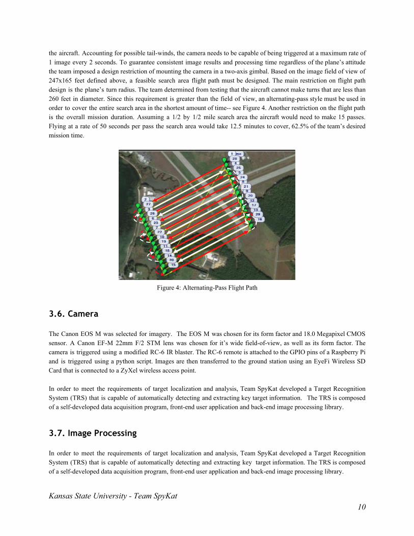
the aircraft. Accounting for possible tailwinds, the camera needs to be capable of being triggered at a maximum rate of 1 image every 2 seconds. To guarantee consistent image results and processing time regardless of the plane’s attitude the team imposed a design restriction of mounting the camera in a twoaxis gimbal. Based on the image field of view of 247x165 feet defined above, a feasible search area flight path must be designed. The main restriction on flight path design is the plane’s turn radius. The team determined from testing that the aircraft cannot make turns that are less than 260 feet in diameter. Since this requirement is greater than the field of view, an alternatingpass style must be used in order to cover the entire search area in the shortest amount of time see Figure 4. Another restriction on the flight path is the overall mission duration. Assuming a 1/2 by 1/2 mile search area the aircraft would need to make 15 passes. Flying at a rate of 50 seconds per pass the search area would take 12.5 minutes to cover, 62.5% of the team’s desired mission time.
Figure 4: AlternatingPass Flight Path
3.6. Camera The Canon EOS M was selected for imagery. The EOS M was chosen for its form factor and 18.0 Megapixel CMOS sensor. A Canon EFM 22mm F/2 STM lens was chosen for it’s wide fieldofview, as well as its form factor. The camera is triggered using a modified RC6 IR blaster. The RC6 remote is attached to the GPIO pins of a Raspberry Pi and is triggered using a python script. Images are then transferred to the ground station using an EyeFi Wireless SD Card that is connected to a ZyXel wireless access point. In order to meet the requirements of target localization and analysis, Team SpyKat developed a Target Recognition System (TRS) that is capable of automatically detecting and extracting key target information. The TRS is composed of a selfdeveloped data acquisition program, frontend user application and backend image processing library.
3.7. Image Processing In order to meet the requirements of target localization and analysis, Team SpyKat developed a Target Recognition System (TRS) that is capable of automatically detecting and extracting key target information. The TRS is composed of a selfdeveloped data acquisition program, frontend user application and backend image processing library.
Kansas State University Team SpyKat 10

3.7.1. Target Recognition Application The Target Recognition Application (TRA) is responsible for detecting and analyzing targets as well as providing the operator with valuable visual feedback. The application is written in the .NET framework and therefore runs only on Windows. In developing our TRA, we focused on two goals: speed and easeofuse. The TRA was built to run in real time and will process images faster than we can currently transfer them. This will allow adequate time to process the image, and for the operator to mark or remove any targets that they may find. In addition to being responsive, the application also requires very little human interaction. Images are received, embedded, and processed autonomously on the ground station. The application allows the operator to easily delete a target in the case of a false positive, as well as manually identify any targets the program may have missed. The application was built to be a singleform application for easeofuse and to minimize memory and screen images. This simple design allows the operator quick access to all the different functionality and views the application provides. A screenshot of the application can be seen in the following figure
Figure 5: Target Recognition Application
As seen in the figure above, the trapezoidal target was automatically detected and analyzed. In addition to placing a white bounding box around the target, the target image is also magnified for the operator's benefit. Two blue rectangles can be seen in the top left hand corner of the full image. These show the operator the minimum and maximum target sizes at the current altitude. These image modifications and other processing are performed by a selfdeveloped library.
3.7.1. Target Detection and Analysis The team developed a .NET library to accurately detect targets as well their location, heading, shape, character, shape color and character color. Multiple third party libraries, such as OpenCV, Tesseract and Leptonica, were utilized in order to speed up development time. The process that was implemented is summarized below.
1. The image is grayscaled using an advanced curvemapping filter. This filter takes into account multiple channels in difference color spaces in order to maximum the chances of detecting targets.
Kansas State University Team SpyKat 11
2. An edge detection algorithm is ran to find edges of interest in the image which are then extracted as contours.
3. Contours are filtered based off the expected size range. The remaining targets of interest are pulled out into
smaller images for processing, while keeping the original image characteristics. This greatly speeds up the system as intensive analysis in only performed on a small portion of the image.
4. A threshold is applied to each target to find objects that meet the specified character to shape size relationship.
The image is then split into a character image and a shape image which are compared to known templates. If the character shape separation is successful additional processing for shape color, character color and target location and heading is performed. However if the separation does not succeed the target is still marked as an area of interest for the operator to evaluate, but is not saved as a target.
3.7.3. QRC The QR Code Detector Application is responsible for detecting a QR code placed within an image and extracting the data contained within the QR code. The application was written in the .NET framework using AForge library for image processing and ZXing library for QR code recognition. For the application to detect the code accurately, the image of the code will be cropped out from the image and enlarged. This may be done either manually or autonomously. With an acceptably sized image, the application will then convert the image into a grayscaled version. Thresholding is applied where all pixels above the threshold are changed to white and any below are changed to black. A blob detection is then run on the image. All quadrilateral blobs are then skewed to be squares and the QR detection is ran on those images. Once the data has been read, the application will display the data within the QR code.
3.8. Ground Station The Ground Station is a complex network of computers that ensures efficient completion of the mission and secure networks and information management. Our Ground Station houses the communication of the autopilot and image analysis systems in a manner that makes missiontime information easier to access to everyone on the flight time. The Ground Station system consists of two smaller stations that keeps information separate and easier to delegate. One station houses the image processing software, which houses a main computer and several monitors so that the Image Analyst can manage every operation separately and simultaneously. Out of five monitors, two monitors display image processing software, another displays the incoming images, and the final two are copies of the Autopilot operator’s screen so that the Image Analyst is updated with the position of the aircraft. The second station maintains the Mission Planner software and the Interoperability and Sense Detect and Avoid tasks. The Autopilot Operator at this station is also in charge of the primary tasks and ensuring the mission is being completed correctly. The main computer is a laptop that has multiple displays to manage the Interoperability task while also completing the main objectives on the main screen. The second station also receives a display from the Image Analyst station in the event that the Autopilot Operator needs to communicate with the Image Analyst. The two stations are separated by metal partitions with holes for networking and display cables to share information. Together these stations make the Razor Ground Station that is base of operations for Team SpyKat and is necessary to minimize information clogging and create an efficient space for the operators to communicate.
Kansas State University Team SpyKat 12
4. Testing and Evaluation Results As previously mentioned, the 2015 Team SpyKat UAS and operating personnel have conducted over 20 test flights, 7 of which were completely autonomous, over the span of nine months in addition to numerous subsystem tests in the lab to date. The following sections explain and interpret the tests and their results to stand as evidence for the expected mission performance.
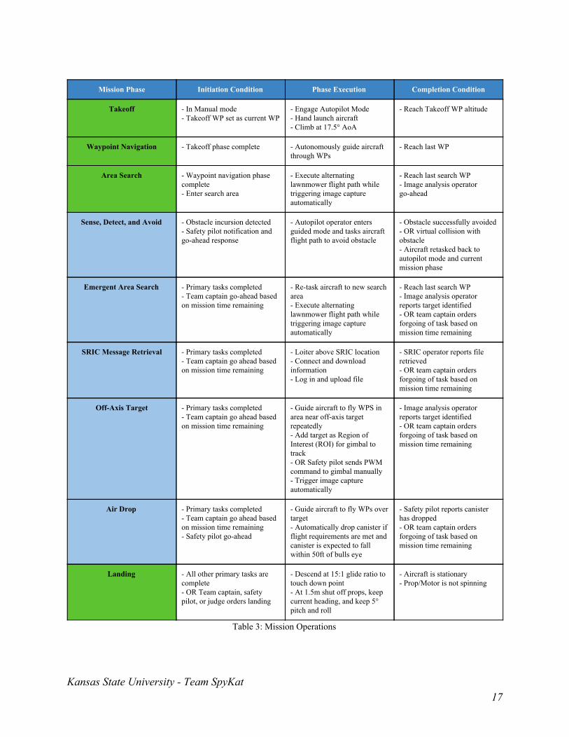
4.1. Mission Operations Each mission phase consists of an initiation condition, phase execution, and a completion condition. Many of the phases can be preempted by the flight director in the event that mission time is running low or system appear to be malfunctioning. Table 3, in the appendix, details each mission phase, primary tasks are in green, while secondary are in blue.
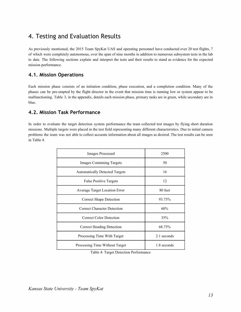
4.2. Mission Task Performance In order to evaluate the target detection system performance the team collected test images by flying short duration missions. Multiple targets were placed in the test field representing many different characteristics. Due to initial camera problems the team was not able to collect accurate information about all images as desired. The test results can be seen in Table 4.
Images Processed 2500
Images Containing Targets 50
Automatically Detected Targets 16
False Positive Targets 12
Average Target Location Error 80 feet
Correct Shape Detection 93.75%
Correct Character Detection 60%
Correct Color Detection 35%
Correct Heading Detection 68.75%
Processing Time With Target 2.1 seconds
Processing Time Without Target 1.8 seconds
Table 4: Target Detection Performance
Kansas State University Team SpyKat 13

4.3. Payload System Performance Our payload integrity has been proven during every test flight as we have been able to fly with consistent accuracy and communication. The last test flights we successfully tested and established the SRIC connection testing at the correct altitude and position using a replicated system to what will be used during the flight.
Only during one flight during autonomous landing did we have an issue where the plane landed and damaged our gimbal and scratched the camera. This was because we were landing on a hill, where all other landings have been on flat or downward sloping surfaces. With some adjustments we believe that our payload system will be safe during flight. The payload system is a crucial part to the competition and so it is tested every flight to make sure all systems work and are free of any issues. Last year we saw issues with our first flight due to interference and noise while on the flight line. To combat that we have tested adjusting frequencies and air vehicle communication with great success.
4.4. Guidance System Performance Initial flight tests in low wind showed sloppy flight path tracking performance with the aircraft overshooting up to 30 meters from the flight path when turning and oscillating around the desired path. The large magnitude of these deviations was the result of poor waypoint placement. The team had created flight paths that required a 20 meter turn radius to be flown accurately, but it was discovered during flight that the turn radius of the aircraft is around 40 meters. Modification of flight plans and tuning the L1 flight path controller created better control over flight path tracking. This procedure reduced the maximum overshoot to 15 meters, a 50% reduction, and more precise tracking throughout flight. It was also noticed that on each turn, the aircraft lost significant altitude, up to 15 meters. Tuning of the Total Energy Control System (TECS) resulted in a much smaller maximum altitude loss when turning of 5 meters.
The system was also tested in high wind conditions, surface winds of greater than 15 knots with gusts above 20 knots. The system was capable of flying, but very large deviations from the flight path were observed. The aircraft had a great deal of difficulty in making turns with the wind which was expected. However, turns into the wind were very tight. In order to follow the flight path the aircraft had to crab into the wind significantly during paths with cross wind. This resulted in yawed images and some missed coverage because the gimbal is only 2 axes. This high wind test flight demonstrated the limitations of team SpyKat’s system. Flight plans will be developed for different wind conditions in order to mitigate the effect of missed aerial coverage by minimizing the amount of flying with crosswinds and by allowing for more room to turn with the wind. The aircraft struggled to gain altitude during the initial few attempts of automatic takeoff, dipping up to 2 ft before climbing. It was determined that by increasing the minimum commanded pitch angle on takeoff and increase the maximum throttle the aircraft would be able to readily gain altitude. The modified auto takeoff control was tested 5 times in varying wind conditions and shown to perform much better than before, no significant dip in altitude was observed. However, increasing the throttle at takeoff caused the system to increase desired airspeed to almost 50 knots the entire flight, making the flight poorly controlled and inefficient. Addition of a DO_CHANGE_SPEED command after reaching the takeoff altitude allowed the system to recover from 100% throttle and maintain a good airspeed of 33 knots.
Kansas State University Team SpyKat 14
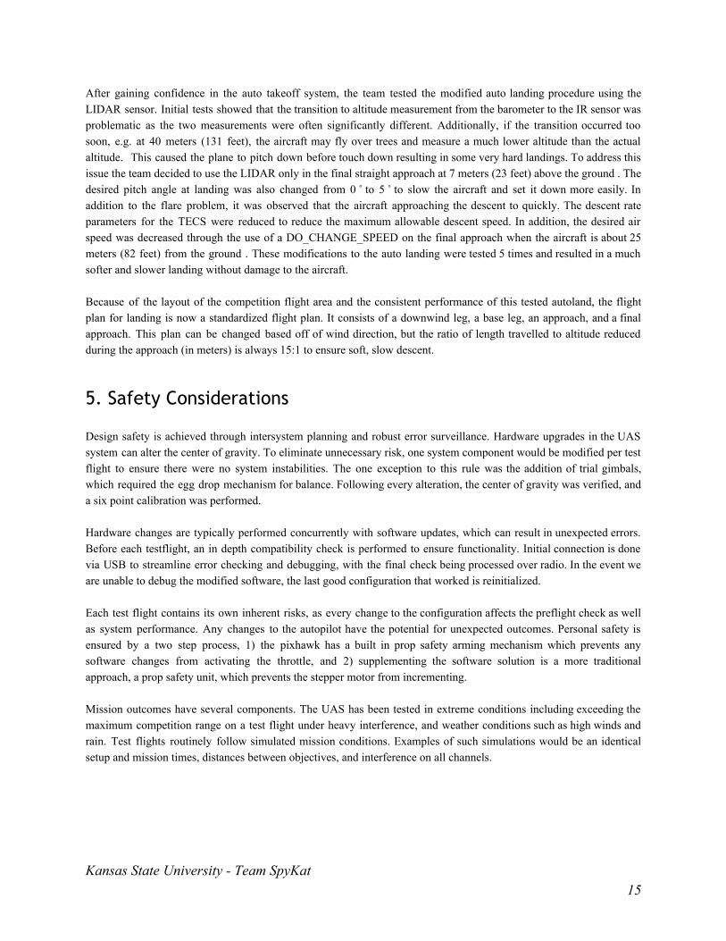
After gaining confidence in the auto takeoff system, the team tested the modified auto landing procedure using the LIDAR sensor. Initial tests showed that the transition to altitude measurement from the barometer to the IR sensor was problematic as the two measurements were often significantly different. Additionally, if the transition occurred too soon, e.g. at 40 meters (131 feet), the aircraft may fly over trees and measure a much lower altitude than the actual altitude. This caused the plane to pitch down before touch down resulting in some very hard landings. To address this issue the team decided to use the LIDAR only in the final straight approach at 7 meters (23 feet) above the ground . The desired pitch angle at landing was also changed from 0 to 5 to slow the aircraft and set it down more easily. In addition to the flare problem, it was observed that the aircraft approaching the descent to quickly. The descent rate parameters for the TECS were reduced to reduce the maximum allowable descent speed. In addition, the desired air speed was decreased through the use of a DO_CHANGE_SPEED on the final approach when the aircraft is about 25 meters (82 feet) from the ground . These modifications to the auto landing were tested 5 times and resulted in a much softer and slower landing without damage to the aircraft.
Because of the layout of the competition flight area and the consistent performance of this tested autoland, the flight plan for landing is now a standardized flight plan. It consists of a downwind leg, a base leg, an approach, and a final approach. This plan can be changed based off of wind direction, but the ratio of length travelled to altitude reduced during the approach (in meters) is always 15:1 to ensure soft, slow descent.
5. Safety Considerations Design safety is achieved through intersystem planning and robust error surveillance. Hardware upgrades in the UAS system can alter the center of gravity. To eliminate unnecessary risk, one system component would be modified per test flight to ensure there were no system instabilities. The one exception to this rule was the addition of trial gimbals, which required the egg drop mechanism for balance. Following every alteration, the center of gravity was verified, and a six point calibration was performed. Hardware changes are typically performed concurrently with software updates, which can result in unexpected errors. Before each testflight, an in depth compatibility check is performed to ensure functionality. Initial connection is done via USB to streamline error checking and debugging, with the final check being processed over radio. In the event we are unable to debug the modified software, the last good configuration that worked is reinitialized. Each test flight contains its own inherent risks, as every change to the configuration affects the preflight check as well as system performance. Any changes to the autopilot have the potential for unexpected outcomes. Personal safety is ensured by a two step process, 1) the pixhawk has a built in prop safety arming mechanism which prevents any software changes from activating the throttle, and 2) supplementing the software solution is a more traditional approach, a prop safety unit, which prevents the stepper motor from incrementing. Mission outcomes have several components. The UAS has been tested in extreme conditions including exceeding the maximum competition range on a test flight under heavy interference, and weather conditions such as high winds and rain. Test flights routinely follow simulated mission conditions. Examples of such simulations would be an identical setup and mission times, distances between objectives, and interference on all channels.
Kansas State University Team SpyKat 15

6. Appendix Task Parameter Expected Performance
Autonomous Flight Take off Objective
Flight Objective
Waypoint Navigation Objective
Landing Objective
Search Area Task Localization Objective
Classification Objective
False Alarm Rate Objective
Secret Message Objective
ADLC Task Automatic Localization Objective
Automatic Classification Objective
False Alarm Rate Objective
Actionable Intelligence Task Identify Target Objective
Emergent Target Task Inflight Retasking Objective
Autonomous Search Objective
Target Identification Objective
SRIC Task SRIC Download Objective
SRIC Upload Objective
Autonomous SRIC Objective
Air Drop Task Release Objective
Drop Accuracy Threshold
OffAxis Target Task Imagery Objective
Classification Objective
Payload Autonomy Threshold
Interoperability Download & Display Server Time Objective
Upload UAS Position Objective
Download & Display Obstacles Objective
Sense, Detect, and Avoid Stationary Obstacles Avoidance Objective
Moving Obstacles Avoidance Threshold
Table 2: Planned Tasks and Performance
Kansas State University Team SpyKat 16
Mission Phase Initiation Condition Phase Execution Completion Condition
Takeoff In Manual mode Takeoff WP set as current WP
Engage Autopilot Mode Hand launch aircraft Climb at 17.5° AoA
Reach Takeoff WP altitude
Waypoint Navigation Takeoff phase complete Autonomously guide aircraft through WPs
Reach last WP
Area Search Waypoint navigation phase complete Enter search area
Execute alternating lawnmower flight path while triggering image capture automatically
Reach last search WP Image analysis operator goahead
Sense, Detect, and Avoid Obstacle incursion detected Safety pilot notification and goahead response
Autopilot operator enters guided mode and tasks aircraft flight path to avoid obstacle
Obstacle successfully avoided OR virtual collision with obstacle Aircraft retasked back to autopilot mode and current mission phase
Emergent Area Search Primary tasks completed Team captain goahead based on mission time remaining
Retask aircraft to new search area Execute alternating lawnmower flight path while triggering image capture automatically
Reach last search WP Image analysis operator reports target identified OR team captain orders forgoing of task based on mission time remaining
SRIC Message Retrieval Primary tasks completed Team captain go ahead based on mission time remaining
Loiter above SRIC location Connect and download information Log in and upload file
SRIC operator reports file retrieved OR team captain orders forgoing of task based on mission time remaining
OffAxis Target Primary tasks completed Team captain go ahead based on mission time remaining
Guide aircraft to fly WPS in area near offaxis target repeatedly Add target as Region of Interest (ROI) for gimbal to track OR Safety pilot sends PWM command to gimbal manually Trigger image capture automatically
Image analysis operator reports target identified OR team captain orders forgoing of task based on mission time remaining
Air Drop Primary tasks completed Team captain go ahead based on mission time remaining Safety pilot goahead
Guide aircraft to fly WPs over target Automatically drop canister if flight requirements are met and canister is expected to fall within 50ft of bulls eye
Safety pilot reports canister has dropped OR team captain orders forgoing of task based on mission time remaining
Landing All other primary tasks are complete OR Team captain, safety pilot, or judge orders landing
Descend at 15:1 glide ratio to touch down point At 1.5m shut off props, keep current heading, and keep 5° pitch and roll
Aircraft is stationary Prop/Motor is not spinning
Table 3: Mission Operations
Kansas State University Team SpyKat 17

Type of Failure Affected Operations Severity Response Status
Loss of Autopilot Comms
Aircraft stability and maneuverability
Lost Comm < 30s Continue on flight path, and attempt to re establish connection
Mission Resume
30s < Lost Comm< 3min Navigate to lost comm waypoint, and attempt to reestablish connection before landing
Mission Compromised, Aircraft Recoverable
Lost Comm > 3min Automatically initiate flight termination sequence
Catastrophic
Loss of 5.0 GHz Data Link Camera Downlink Transmission, Flight Path ReTasking
Link Down < 120s Reestablish camera link and retask autopilot to scan unsearched area again.
Mission Resume
Link Down > 120s Land UAS and re establish camera link. If mission time remains, fly over unimaged search area.
Mission Resume
Loss of GPS signal Autopilot Navigation Lost Signal Safety Pilot will take control over RC and land plane
Mission Compromised, Aircraft Recoverable
Loss of Motor Power Aircraft stability and maneuverability
Intermittent or Full loss of Power
Safety Pilot will take RC control and perform an emergency landing
Mission Compromised, Aircraft Recoverable
Loss Payload Power Autopilot and Camera Functionality
Lost Power < 60s Retask autopilot to circle nearest waypoint and wait to reestablish power. Scan unsearched area again.
Mission Resume
Lost Power > 60s Safety Pilot will take control over RC and land plane. Reestablish power and if mission time remains, fly over unimaged search area.
Mission Resume
Mission Compromised, Aircraft Recoverable
Autopilot Ground Station Malfunction
Autopilot Functionality Software or Hardware Failure
Safety Pilot will take control over RC and land plane.
Mission Compromised, Aircraft Recoverable
Imaging Computer Malfunction
Camera Functionality Software or Hardware Hover nearest waypoint, and restart imaging program
Mission Resume
Image Processing Computer Malfunction
Image Processing Functionality
Software or Hardware Failure
Continue with mission and restart image analysis program
Mission Resume
Vehicle Damage Aircraft Stability and Maneuverability
Loss of one servo, hole in MonoKote, slight landing gear damage
Autopilot attempts to compensate for damage
Mission Resume
Autopilot cannot control aircraft due to significant damage
Safety Pilot will take RC control and perform an emergency landing
Mission Compromised, Aircraft Recoverable
Safety Pilot cannot control aircraft
Initiate Flight Termination Sequence Catastrophic
Kansas State University Team SpyKat 18