Embed Size (px)
Citation preview

TEAM: SMART BIRD UNIVERSITY: POLYTECHNIQUE MONTREAL 0
JOURNAL PAPER
AUVSI SEAFARER CHAPTER
13TH ANNUAL STUDENT UAS COMPETITION
MAY 2015
JOURNAL PAPER AUVSI SEAFARER CHAPTER 13TH ANNUAL STUDENT UAS COMPETITION
TEAM: SMART BIRD UNIVERSITY: POLYTECHNIQUE MONTREAL i
ABSTRACT
Throughout our education as engineering students, we learn theoretical knowledge, but do not get the chance to work it with and enhance it through practice. Being able to participate in the AUVSI Seafarer chapter student competition is important in order to learn by achieving and not only by learning.
Smart Bird is a technological committee from Polytechnique Montréal, which regroups students from the computer engineering, electrical engineering, mechanical engineering and aerospace engineering sphere. They are all united under the single challenge of creating a UAV.
This year, the ideology of the team is to integrate existing components and fine tune
them for the Smart Bird team’s needs. Most components have been rigorously tested and have served in competitions or tests to simulate competitions. The airplane is an almost ready to fly Sig Rascal fitted with an ArduPilot 2.6 mega as its autopilot. For detection purposes, the UAS uses a standard Nikon high definition camera. The image will be stored in the UAS on an onboard hard drive and will also be transmitted in real time to the ground station. This redundancy allows the team to ensure that the data can be processed and the mission accomplished.
The UAS has been tested in flight for safety and competence purposes and results from the automation and camera are promising. The automation and detection software have been thoroughly tested. These modules answer the requirements for the competitions and the team’s expectations.

JOURNAL PAPER AUVSI SEAFARER CHAPTER 13TH ANNUAL STUDENT UAS COMPETITION
TEAM: SMART BIRD UNIVERSITY: POLYTECHNIQUE MONTREAL ii
TABLE OF CONTENTS ABSTRACT I TABLE OF CONTENTS II
SYSTEMS DESCRIPTION AND ENGINEERING APPROACH 1 1.1 MISSION REQUIREMENTS ANALYSIS 1 1.2 DESIGN RATIONALE 1 1.3 EXPECTED TASK PERFORMANCE 1 1.4 PROGRAMMATIC RISKS AND MITIGATION METHODS 2
DESCRIPTION OF THE UAS DESIGN 3 2.1 METHOD OF AUTONOMY 3 2.2 DATA LINK 3
2.2.1 SAFETY PILOT CONTROL 3 2.2.2 FLIGHT DATA TRANSFER 3 2.2.3 IMAGES DATA TRANSFERT 4
2.3 MISSION PLANNING AND GROUND STATION 5 2.3.1 MISSION PLANNING 5 2.3.2 GROUND STATION 5
2.4 DATA PROCESSING 5 2.4.1 DATA PROCESSING HARDWARE 5
2.5 DATA PROCESSING SOFTWARE 6 2.6 AIRCRAFT SYSTEM 8 2.7 PAYLOAD 9
TESTS AND EVALUATIONS RESULTS 10 3.1 MISSION TASK PERFORMANCE 10 3.2 PAYLOAD SYSTEM PERFORMANCE 10 3.3 GUIDANCE SYSTEM PERFORMANCE 11 3.4 EVALUATION OF TESTS RESULTS 11
SAFETY AND RISK MANAGEMENT 12 4.1 SPECIFIC SAFETY CRITERIA FOR BOTH OPERATIONS AND DESIGN 12 4.2 SAFETY RISKS MITIGATION METHODS 12
4.2.1 SAFETY MITIGATION THOUGH DESIGN 12 4.2.2 SAFETY ORGANIZATIONAL CHART 13
CONCLUSION 15

JOURNAL PAPER AUVSI SEAFARER CHAPTER 13TH ANNUAL STUDENT UAS COMPETITION
TEAM: SMART BIRD UNIVERSITY: POLYTECHNIQUE MONTREAL 1 of 15
SYSTEMS DESCRIPTION AND ENGINEERING APPROACH
1.1 MISSION REQUIREMENTS ANALYSIS
Given the hardware and the tests done, the team is confident in its ability to execute the following tasks:
Autonomous flight
Search area
Auto detect, localize and classify
Actionable intelligence
Emergent target
The autonomous flight task will be carried out by the ArduPilot and the mission planned software. The autonomous flight will have manual takeoff and landing but will maintain autonomous flight within ±50 ft. These tasks have been tested and passed during flight in the Montréal region. During the tests the emergent target situation was tested and the autopilot had no issue to include the new point in its flight route.
The search area task will be conducted in autonomous flight with a smart bird
proprietary software. The software passes through the pictures and autonomously detects objects. Furthermore, the team can manually add targets to those found by the software in order to ensure none are missed. The software is able to detect all characteristics of the target and thus, the actionable intelligence task will be done.
1.2 DESIGN RATIONALE
The design Smart Bird decided to opt for this year was to use many proven and
rigorously tested components. These components are then made to work together and meet the needs of the team and of the competition. The only part of the UAS which does not comply with this mentality is the detection software which is home made by software engineering students. The software is overseen by a master’s degree student whose subject is form detection and computer vision. However, the airframe, automation system, camera and antenna were bought. A lot of work was still made to ensure that the systems would work as required.
1.3 EXPECTED TASK PERFORMANCE
With the UAS that Smart Bird has built, the team firmly believes that it will be able to achieve fully controlled flight and waypoint navigation. The UAS will be able to automatically search the area and identity enough characteristics from the targets to meet the requirements of the detection. Furthermore, the UAS should do some automatic detection. If the actionable intelligence task will be fulfilled. The expected task performance is high since all separate modules worked in the flight tests prior to the competition. Furthermore, an integrated test proved that the airplane was able to fly without going into the no-fly zone, take pictures and process the images.

JOURNAL PAPER AUVSI SEAFARER CHAPTER 13TH ANNUAL STUDENT UAS COMPETITION
TEAM: SMART BIRD UNIVERSITY: POLYTECHNIQUE MONTREAL 2
1.4 PROGRAMMATIC RISKS AND MITIGATION METHODS
In order to ensure safety, the team has thoroughly tested its systems and has built a block diagram listing all possible events and the actions that the team must undertake in order to ensure that any issue is safely controlled. Figure 5 on page 14 shows the failsafe organization chart which is used during the tests and the competition. The chart identifies and catalogues all risks which may occur during the competition, plans for these risks and shows in a clear and orderly manner the actions to take by the flight team. Furthermore, the failsafe requirements were tightened in order to never encounter any issue. The return to home mode engages 10 seconds after loss of communications and the automation system will automatically engage the kill switch after 2 minutes of signal loss.

JOURNAL PAPER AUVSI SEAFARER CHAPTER 13TH ANNUAL STUDENT UAS COMPETITION
TEAM: SMART BIRD UNIVERSITY: POLYTECHNIQUE MONTREAL 3
DESCRIPTION OF THE UAS DESIGN
2.1 METHOD OF AUTONOMY
To ensure the autonomous control of the UAV during flight, Smart Bird uses the
ArduPilot Mega 2.6 as its autopilot. This important system provides automatic control of the servomotors and throttle but can still give manual control to the safety pilot if need be. Also, it is used to provide information of the aircraft’s status to the ground station. The choice of the aerial platform leaned toward the ArduPilot Mega due to his reliability, maturity, simplicity and offers a user-friendly interface. The PX4 autopilot was another autopilot which was considered and even if it has really impressive specifications and is more recent, it doesn’t offer the same reliability as ArduPilot. The ArduPilot is open-source, uses the ATMEGA2560 microcontroller and allows the UAV to follow pre-determined waypoints and ensure the stabilisation during flight using Mission Planner. The board comes with onboard sensors, such as gyro, accelerometer, magnetometer and barometer. It is also possible to connect an external GPS, which in this case is the 3DR uBlox LEA-6H. Furthermore, it is possible to switch from autonomous flight to manual control and it features also a monitoring system for batteries. Technical specifications can be found in Table 1.
The 2.6 version presents new features from the precedent versions used during past
competitions. Indeed, it’s now possible to estimate wind using an airspeed sensor and because of the addition of this system, a new fail safe system is used called dead reckoning. New support for landing for wheeled aircraft is implemented. The autonomous landing was tested but the tests proved the platform to be too unpredictable and in order not to lost secondary tasks points, the autonomous landing task was cancelled. The flight data, along with the system’s health, is transferred in real time via the Mavlink protocol with RFD 900 module. The receiver, another RFD 900, is connected to the base station.
2.2 DATA LINK
2.2.1 SAFETY PILOT CONTROL
For the UAS manual control, the safety pilot uses a DX8 transmitter and receiver. The
receiver is linked to the autopilot within the UAS. The DX8 receiver and transmitter use the 2.4 Hz band to maintain data link and manual control over the UAS. At any time during the mission, the safety pilot can take over control of the aircraft by switching the modes on his controller. This transmitter emits on the 2.4 GHz radio frequency.
2.2.2 FLIGHT DATA TRANSFER
For the data transfer between the autopilot, the sensors and the ground station, the team
uses the RFD 900. The RFD 900 is designed for long rage communications. The RFD 900 uses

JOURNAL PAPER AUVSI SEAFARER CHAPTER 13TH ANNUAL STUDENT UAS COMPETITION
TEAM: SMART BIRD UNIVERSITY: POLYTECHNIQUE MONTREAL 4
the 900 MHz radio frequency. Testing the RFD 900 proved it to be a good platform. The technical specifications are given in Table 11:
Table 1: RFD 900 specifications
Indoor/Urban up to 450ft (140m) Frequency Range 902-928 MHz Outdoor line-of-sight up to 1.8 miles (3 km) Receiver Sensitivity 121 dBm Transmit Power Output 1 W (+30 dBm) RF Data Rate 156.25 kbps Advanced
Networking & Security
2.2.3 IMAGES DATA TRANSFERT
To ensure image data transfer, the Smart Bird team uses two 2.4 GHz modules which
interact with one another. On the ground station, the module used is the Bullet M2 from Ubiquiti. It creates a powerful outdoor access point. This product has 600 mW of power and can be connected to every type of long range antenna. The antenna used by Smart Bird is a parabolic antenna grid of 24 dBi. The two principal characteristics of this type of antenna is its high gain and the good performance at long range. However, this antenna has a small opening angle. A good antenna tracker is require to keep data link. As such, the team has installed the parabolic antenna on a controlled moving head. The Martin MAC500 moving head was reconfigured to work on 120V and to follow the aircraft at all times. With the combination of the Ubiquiti product and this antenna, a good equivalent isotopic radiated power (EIRP) is achieved for the data transfer. The Ubiquiti product can technically transfer 100 mbps of data rate. Theoretical data rates as this were only achieved at a very short distance. During the tests, with the directional antenna perfectly pointed at the aircraft, the data rate was usually between 1 and 5 Mbps. As such, the initial images taken by the camera, have to be compressed. Fortunately, the Nikon D3200 chosen to take pictures is able to compress images to 3Mb at a 6016 x 4000 resolution. After the onboard processing is done, an omnidirectional antenna is used to transfer the data through the Bullet M2. The transmitter, the Picostation2, is also an Ubiquiti product and it’s compatible with the wireless protocol TCP/IP and the Ubiquiti breakthrough AirMax technology. These wireless radio are powerful TDMA base stations and are made for the long range communication required in the UAS. At long range, this type of antenna is perfect, but the difficulties lie in close range because of the directionality of the antenna. During the tests, this flaw was proven to be unimportant as the moving head would move fast enough to keep track of the airplane during the flight, even at very close range.
1 RDFESIGN. (2014). RFD900 Radio Modem. Consulted on May 21st 2014, from : http://rfdesign.com.au/index.php/rfd900
JOURNAL PAPER AUVSI SEAFARER CHAPTER 13TH ANNUAL STUDENT UAS COMPETITION
TEAM: SMART BIRD UNIVERSITY: POLYTECHNIQUE MONTREAL 5
2.3 MISSION PLANNING AND GROUND STATION
2.3.1 MISSION PLANNING
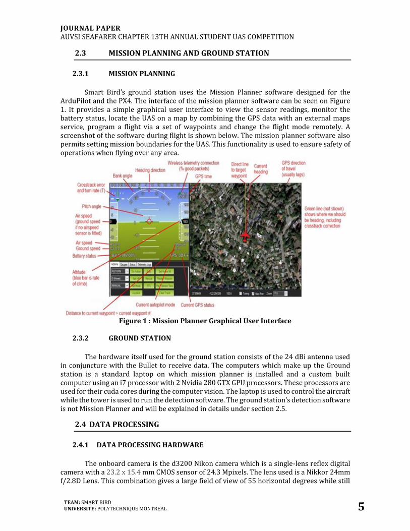
Smart Bird’s ground station uses the Mission Planner software designed for the ArduPilot and the PX4. The interface of the mission planner software can be seen on Figure 1. It provides a simple graphical user interface to view the sensor readings, monitor the battery status, locate the UAS on a map by combining the GPS data with an external maps service, program a flight via a set of waypoints and change the flight mode remotely. A screenshot of the software during flight is shown below. The mission planner software also permits setting mission boundaries for the UAS. This functionality is used to ensure safety of operations when flying over any area.
Figure 1 : Mission Planner Graphical User Interface
2.3.2 GROUND STATION
The hardware itself used for the ground station consists of the 24 dBi antenna used in conjuncture with the Bullet to receive data. The computers which make up the Ground station is a standard laptop on which mission planner is installed and a custom built computer using an i7 processor with 2 Nvidia 280 GTX GPU processors. These processors are used for their cuda cores during the computer vision. The laptop is used to control the aircraft while the tower is used to run the detection software. The ground station’s detection software is not Mission Planner and will be explained in details under section 2.5.
2.4 DATA PROCESSING
2.4.1 DATA PROCESSING HARDWARE
The onboard camera is the d3200 Nikon camera which is a single-lens reflex digital camera with a 23.2 x 15.4 mm CMOS sensor of 24.3 Mpixels. The lens used is a Nikkor 24mm f/2.8D Lens. This combination gives a large field of view of 55 horizontal degrees while still

JOURNAL PAPER AUVSI SEAFARER CHAPTER 13TH ANNUAL STUDENT UAS COMPETITION
TEAM: SMART BIRD UNIVERSITY: POLYTECHNIQUE MONTREAL 6
giving a maximum resolution of 3 cm for an object at a distance of 100 m. Furthermore, the open source library libGphoto2 is used to control it and transfer images automatically or manually. The software is installed on a raspberry pi. The camera is able to compress the pictures with a resolution of 6,016 x 4,000 to a mean size of 3MB per picture using JPEG compression. Essentially, the raspberry pi sends the command to the camera to take pictures and when the picture is taken, the camera signals it back. Afterwards, the image is saved on a SD drive and transmitted through 2.4GHz to the ground control station.
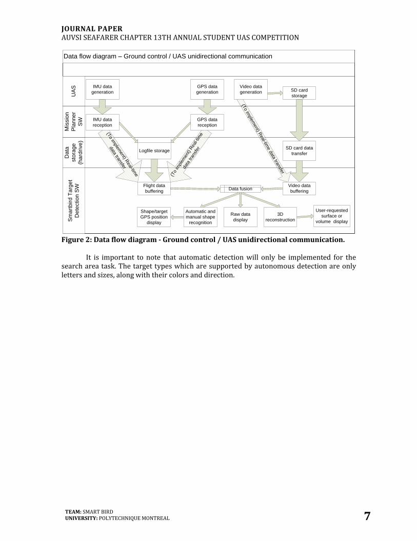
As shown in Figure 2, IMU and GPS data reception is already managed by the Mission Planner software using the Mavlink protocol. Thereby, the team only needs to provide a wireless network mean between the UAS and the ground control station. In the case of Smart Bird's UAS, the image transfer is created by the BulletM5 and Picostation2. Mission Planner stores every IMU and GPS data received as well as their corresponding timestamps in a comma-separated value (.csv) log file.
2.5 DATA PROCESSING SOFTWARE
The software used by Smart Bird will need to be executed in parallel with the Mission
Planner software since they are both in real time. Therefore, the algorithms will be executed through usage of GPU so the CPU is not overcharged. The algorithms used come from the OpenCV open source library and are either Haar Casade or a mixture of HOG features with a SVM classifier (HOG+SVM). Haar Cascade is faster that HOG+SVM but is less precise.
The detection algorithm software then reads both the flight data from the log files
generated by Mission Planner, and the video data transferred or on the SD card after the flight. Thereafter, the software fuses them and keeps them in its internal data store for further processing. The nature of this post-processing consists of:
1. A 3D reconstruction of the scene below the UAS during its flight, thereby enabling the calculation of volumes or surfaces of specific areas of the ground shown in a video frame.
2. A calculation of the GPS coordinates of the center of regions of interest (i.e. targets) which are automatically detected or manually selected from a video frame a priori.
JOURNAL PAPER AUVSI SEAFARER CHAPTER 13TH ANNUAL STUDENT UAS COMPETITION
TEAM: SMART BIRD UNIVERSITY: POLYTECHNIQUE MONTREAL 7
Flight data
buffering
Data flow diagram – Ground control / UAS unidirectional communication
Sm
art
bird
Ta
rge
t
De
tectio
n S
W
Da
ta
sto
rag
e
(ha
rdrive)
Mis
sio
n
Pla
nn
er
SW
UA
S
(To im
ple
ment) R
eal-tim
e d
ata
transfe
r
(To im
plement) R
eal-time
data transfer
(To
impl
emen
t) R
eal-t
ime
data
tran
sfer
Video data
generation
User-requested
surface or
volume display
Shape/target
GPS position
display
Video data
buffering
GPS data
reception
3D
reconstruction
GPS data
generation
IMU data
reception
Data fusion
Automatic and
manual shape
recognition
SD card
storage
Logfile storageSD card data
transfer
IMU data
generation
Raw data
display
Figure 2: Data flow diagram - Ground control / UAS unidirectional communication. It is important to note that automatic detection will only be implemented for the search area task. The target types which are supported by autonomous detection are only letters and sizes, along with their colors and direction.

JOURNAL PAPER AUVSI SEAFARER CHAPTER 13TH ANNUAL STUDENT UAS COMPETITION
TEAM: SMART BIRD UNIVERSITY: POLYTECHNIQUE MONTREAL 8
2.6 AIRCRAFT SYSTEM
The airframe used by Smart Bird is the Kadet Senior AFR by Sig Mfg. Co. This model is a large size “trainer class” RC airplane. With its high wing monoplane and its conventional tail, the Sig Kadet Senior AFR provides high stability, sensitive controls, and high lift. The specifications of the airplane can be found in Table 2: Aircraft specifications2. The airframe can be seen on Figure 3 and Figure 4.
Table 2: Aircraft specifications
Wingspan : 78 in. Wing Chord : 16 in. (root)
Wing Area : 1150 sq. in. Empty Weight : 6 lbs
Length : 62 in. Max. Operation Weight : 21 lbs
The motor used is a Scorpion SII4035-470kV Outrunner electric motor powered by a pair of 22,2 V, 6 cells, 5000 mAh Lithium-Polymer batteries and controlled by a Scorpion Opto Commander 50V 130A electronic speed controller. The motor was chosen to be bigger than the basic plane design required to increase the airplane’s efficiency, short take-off performances, flying airspeed and payload capacity.
Figure 3: Airframes used for testing and competition
Figure 4: Smart Bird Airframes in flight
2 SIG Mfg. Co. Kadet Senior. Consulted on May 15nd 2015, from : http://www.sigmfg.com/IndexText/SIGRC58.html

JOURNAL PAPER AUVSI SEAFARER CHAPTER 13TH ANNUAL STUDENT UAS COMPETITION
TEAM: SMART BIRD UNIVERSITY: POLYTECHNIQUE MONTREAL 9
2.7 PAYLOAD
All of the previous systems constitute the payloads and their functionality. Table 3 lists all of the different components of the payload along with their physical specifications which are used to set the airframe's center of gravity.
Table 3: Payload
Amount Name Length Width or Diameter Height Volume Weight
[in] [in] [in] [in3] [lb]
1 Pitot Tube 0.87 0.87 0.47 1.3 0.00661
1 GPS 1.57 0.63 0.28 0.3 0.01543
1 RFD 900 1.18 2.24 0.50 1.3 0.03197
1 Raspberry pi 3.37 2.20 0.83 6.1 0.09921
1 Internal 60GB SSD 2.76 3.94 0.35 3.8 0.16976
1 Nikon D3200 4.92 3.78 3.03 56.4 1.70417
1 Picostation M2 5.35 1.54 0.79 6.5 0.22046
1 ArduPilot MEGA 2.6 2.60 1.57 0.47 1.9 0.03086
2 LIPO 6s 22Batteries 6.61 1.93 1.73 22.1 1.51501
4 LIFE Batteries 4.13 1.93 0.59 4.7 0.37523
Total 104.5 4.16872

JOURNAL PAPER AUVSI SEAFARER CHAPTER 13TH ANNUAL STUDENT UAS COMPETITION
TEAM: SMART BIRD UNIVERSITY: POLYTECHNIQUE MONTREAL 10
TESTS AND EVALUATIONS RESULTS
Many tests were made throughout the UAS life. The first tests occur at Polytechnique, doing various ground tests. These tests are usually range tests and basic pictures taken by the camera. These tests are a great way of finding issues before going to the field. Further tests are made at the field at which the team has a Special Flight Operating Certificate from Transport Canada. The SFOC is a document which allows the team to fly the UAS under certain limitations and supervisions. The tests at the field are usually systems tests and in the end, integration tests to ensure that all systems are working perfectly in conjunction with each other. A copy of the SFOC can be given at any time if required.
3.1 MISSION TASK PERFORMANCE
Tests ensure that the team is ready for the mission tasks are made at the field. Tests on the automation system and on the detection system were done. The tests on the automation system will be discussed further in the Guidance system performance section. The detection and data process system was tested for precision. The UAS took many pictures of different landmarks, houses, targets and more and were then tested for precision on the ground. Initially, the images were transferred by USB connection when the aircraft landed and processed by the detection software. Lately, the integration tests proved that the team was able to send the date in real time to be then analysed. The precision of the data process system was judged good when compared with the true GPS coordinated of the targets which were captured. Ground tests of the transmission system were prior done and were convincing. The tests showed good data rate and good data transfer health. There were few errors in the system left at the end of the many ground tests.
3.2 PAYLOAD SYSTEM PERFORMANCE
This section will not be talking about the autopilot performance even if it is payload; it will be further discussed in the section 3.3. The rest of the payload consists of the camera, the raspberry pi board and the Picostation2. The performance of the batteries will be left out of the discussions as they work perfectly and are of no great engineering challenge. These batteries are changed every year to ensure the peak performance and eliminate any energy related risks. The Nikon camera is closely linked to the raspberry pi as the board controls the data from the camera and its performances. During the initial flights, there were many issues with the shutter time and focus. Using the focusing techniques of the camera and lenses proved essential to fix these issued. Optimizing the settings and the controls of the camera Nikon and of the raspberry pi improved the shutter speed. Further flight tests were conclusive as the camera was able to take great pictures and save them appropriately within the SSD connected to the board. Real time tests were conducted on ground and in flight and proved that the rate of capture of images was slow enough to permit the transmission to send the images at the right time. The initial data rates that were found through ground tests were poor but once
JOURNAL PAPER AUVSI SEAFARER CHAPTER 13TH ANNUAL STUDENT UAS COMPETITION
TEAM: SMART BIRD UNIVERSITY: POLYTECHNIQUE MONTREAL 11
the airplane is in the air and out of the city’s interference, the data rates were much higher. Exposition time also required to be fine-tuned as initially, the contrasts of the image were off and made some pictures completely white.
3.3 GUIDANCE SYSTEM PERFORMANCE
For the guidance system, the tests were separated in two categories: ground and flight
tests. On the ground, the team did the calibration of the sensors, of the autopilot and of the servomotors. The different flight modes were also tested. The RC communication, the power and the surface movements were the main focus of the different modes tests. Afterwards, range tests for the data link and the communication between the autopilot and the ground station was done to know the limits. As the tests results were satisfying, the next step was to fly the UAS in manual mode. This way, it was possible to make sure that the ground tests were replicated in the air. Data link was proven reliable as the ground station could receive data without any loss at a distance of 3500 feet. Once the UAS responded accordingly to the inputs, autonomous flight modes was engaged and tests were made to configure the PID controllers. This allows the aircraft to respond in quick and precise manoeuvers. Finally, some missions were implemented to confirm that everything was working as expected. This also allowed to verify that the failsafe systems, boundaries and return to land worked well. As UAS was monitored and controlled without any issue, the Smart Bird team is confident in its guidance system. It will ensure a fully functional flight.
3.4 EVALUATION OF TESTS RESULTS
Integrated tests were also conducted with wooden templates of targets. The target was
treated as an emergent target as the GPS coordinates were added after take-off. The target’s GPS location were known and the calculated coordinates were within 75 ft.
Further tests will be conducted throughout the summer but the tests seemed very
promising, the Smart Bird team evaluates that the mission will be accomplished successfully. The guidance system has been thoroughly tests on ground and at the field. The detection system has also been tested on ground and was very promising.
JOURNAL PAPER AUVSI SEAFARER CHAPTER 13TH ANNUAL STUDENT UAS COMPETITION
TEAM: SMART BIRD UNIVERSITY: POLYTECHNIQUE MONTREAL 12
SAFETY AND RISK MANAGEMENT
4.1 SPECIFIC SAFETY CRITERIA FOR BOTH OPERATIONS AND DESIGN
In order to achieve safe flight, the UAS has to undergo safety checks and the design of the UAS was made to ensure safety. The following criteria are asked for the AUVSI competition and more safety systems were added by the Smart Bird team.
1. The aircraft and the pilot must also comply to the 2014 official AMA safety code; 2. The aircraft is required to be less than 55 lbs.; 3. The aircraft is required to no exceed 100 KIAS; 4. The UAS must show at all times many information on the UAS to ensure that it doesn't
leave the no-fly boundaries 5. The pilot must be able to take manual override at any phase of the flight; 6. The pilot must be able to activate flight termination; 7. The aircraft must set itself in RTL mode if communication is lost for more than 30 seconds; 8. The kill switch must be automatically triggered if communication is lost for more than 3
minutes; 9. A kill switch must be installed within the airplane which will put the UAS is a downward
spiral. 10. Exotic batteries must not be used; 11. All batteries within the vehicle must be brightly colored; 12. The airplane must be brightly colored.
4.2 SAFETY RISKS MITIGATION METHODS
4.2.1 SAFETY MITIGATION THOUGH DESIGN
1. The pilot has read and complies with the AMA safety code. The team has also taken
knowledge of the safety code and follows it; 2. The aircraft is around 20 lbs. because of limitations set by other competitions; 3. The top speed achieved during test flights was 90 km/h which translates to 49 knots. The
speed was taken by the pitot tube onboard and therefore was indicated air speed; 4. The mission planner software shows positions of the UAS at all times, the positions of the
boundaries and the route taken by the UAS. The attitude, altitude and airspeeds are also displayed. If any more information is required by the judges it will be provided;
5. The receiver of the DX8 transmitter being separate from the RFD, the pilot is able to take control over the UAS at all times;
6. The flight termination is set by the pilot in a manner that if the pilot closes the DX8 transmitter during flight, the UAS will automatically set itself in flight termination. As such, if DX8 transmitter data is lost, the UAS will automatically terminate flight;
7. The Smart Bird team found that 30 seconds could be deterrent for the mission and could sometimes let the UAS fly out of boundaries. Therefore, the system automatically engages return to home if signal is lost for more than 10 seconds;
8. Since the normal airspeed recorded during the tests was around 50 km/h, the UAS could potentially travel a 2.5 km (1.56 miles) distance prior to the kill switch triggering. The

JOURNAL PAPER AUVSI SEAFARER CHAPTER 13TH ANNUAL STUDENT UAS COMPETITION
TEAM: SMART BIRD UNIVERSITY: POLYTECHNIQUE MONTREAL 13
team has then set the time limit to 1.5 minutes which usually let the UAS come back to home and only travel within a radius of 1.25 km (0.78 miles);
9. The kill switch has been implemented; 10. The batteries used within the UAS are regular lithium polymer and lithium iron phosphate
batteries; 11. The batteries have been wrapped in bright colored tape; 12. The airplanes are either red or blue, which are bright colors very easy to discern.
4.2.2 SAFETY ORGANIZATIONAL CHART
In order to ensure the safety of the operations and to know readily actions to take in the event of a failure, an organizational chart was created. The chart can be seen on the next page as Figure 5. This chart lists every failure event and the required actions to control the failure and prevent harm. If any problem arises, the flight team knows what action to take. The flight team and the pilot both know of the chart and know what actions to take in the event of any failure. As per the CONOPS, the kill switch which is also the flight termination method is simply a controlled downward spiral. Flight termination for fixed wing is describes as follow:
• Throttle closed • Neutral elevator • Full right rudder • Full right aileron
Some clarifications had to be made and are notes by numbers followed by an asterisk in the next table. These are the notifications:
1*. To determine whether the control surface failure is due to a mechanical or an electronic problem, activate the back-up receiver and observe if the UAS is responding to the flight commands. If it is, it’s an electronic problem. Otherwise, it’s a mechanical problem.
2*. ArduPilot manual mode enables the pilot to take over the commands directly, via the ArduPilot.
3*. Auto termination of flight is preprogrammed in the ArduPilot to automatically enters the downward spiral when the communication with the aircraft has been lost for more than two minutes
4*. ArduPilot manual mode enables the pilot to take over the commands directly, via the ArduPilot.

JOURNAL PAPER AUVSI SEAFARER CHAPTER 13TH ANNUAL STUDENT UAS COMPETITION
TEAM: SMART BIRD UNIVERSITY: POLYTECHNIQUE MONTREAL 14 of 15
Figure 5 : Failsafe organizational chart

JOURNAL PAPER AUVSI SEAFARER CHAPTER 13TH ANNUAL STUDENT UAS COMPETITION
TEAM: SMART BIRD UNIVERSITY: POLYTECHNIQUE MONTREAL 15 of 15
CONCLUSION
In conclusion, the strategy the Smart Bird team will employ is the maximum amount of automation within the flying tasks and a hybrid automatic and manual system for the detection in order to ensure that all targets can be correctly identified. The team will be using the ArduPilot autopilot in conjunction with the RFD 900 to control automatically the UAS. The ground station will be equipped with the Mission Planner software. The detection system will be real time software which used a directional antenna to transfer the images and open source software to help with the automatic detection of forms. The images will be transmitted by a Picostation and a Bullet and taken with a Nikon D3200. The tests that were made were very promising and few tests are still to be done. The automation system was completely tested and proved to be quite reliable. The detection system revealed to yield precise GPS coordinated and the images transfer in flight showed great promise. Finally, the system has proven to be extremely safe. Checklist and charts are employed to ensure that no mistakes are made during the operations and the Smart Bird team has also given themselves harder safety criteria to ensure harm to no one and nothing. The team is then ready to fly and eager to participate in the competition.