Embed Size (px)
Citation preview
2010 Best View (30GW)
ASWG
DHMG
SWHN
MOSG
SHME
WRSN
DHID
FILA
WMZD
SHPS & S2PS
QDFA
SASNBECH
QURM
ADST
REEM
SDYT
TWPS
ICAD
To Salwa 400kV grid Station (KSA)
GCSL
Abu Dhabi Islands’(AD)
Northern Emirates(NE)
Western region (WR)
TANE
SASN
Eastern Region
(ER)
BHYG
MHWG
BHYG
SMKG
AJMN
S3PS
RWSGBAAB
BRKA
MRPS
FYAGHMEM
FJCT
400kV tower (double circuit)
400kV Cable Single Circuit
400kV grid station
2012 Seven Year Electricity Planning Statement (2013-2019)
Power Network Development Department Asset Management Directorate
December 2012
TRANSCO/AMD/PNDD TRANSCO 2012 7YPS (2013-2019) December 2012 Page 2 of 96 Main Report
Forward
I have the pleasure in releasing the 2012 Seven Year Electricity Planning Statement (7YPS) for
transmission within the Emirate of Abu Dhabi and, where appropriate, our network outside of the
authorized area in the period 2013-2019. In producing this document, we have endeavored to
ensure that our customers, both existing and future, are presented with an opportunity to
understand the scale and type of transmission network operated by us. We have sought to ensure
that customers and other stakeholders are able to identify areas of the network where additional
investment is proposed in order to increase available capacity or otherwise ensure that network
performance continues to attain the targets expected from such a critical infrastructure provider.
This is the third 7YPS released in response to Condition 15 of the Transmission and Despatch
Licence that provides detailed short to medium-term plans for the transmission network. The plans
included in the 7YPS are linked to the needs and investment requirements and are based on the
network development strategy covering the period 2010-2030 that places much greater emphasis
on the trends and drivers which provides a long-term vision for taking the transmission system
forward consistent with Government’s 2030 vision.
Feedback on this 7YPS is most welcome in order that TRANSCO is able to continue to adjust its
planning and development strategies to meet the regulatory, customer and stakeholder
requirements and expectations.
Copies of the approved 7YPS can be downloaded from our website www.transco.ae. Dr. Najib H Dandachi Asset Management Director

TRANSCO/AMD/PNDD TRANSCO 2012 7YPS (2013-2019) December 2012 Page 3 of 96 Main Report
Table of Contents
Main Report Forward………………………………………………………………………………………..........2 Table of contents………………………………………………………………….………...……....3 Acronyms and definitions…………………………………………………………………..............5 Executive summary………………………………………………………………….……....…..….8
1 Introduction…………………………………...…………………….……………….….....…23
2 Network development strategy……………………………………………………..….....….27
3 Demand-generation background……………..………...………………………………..…...39
4 Planned transfers…………….…..……………………………………………………..…….47
5 Evolution of transmission network……………………………………..……………..……..50
6 Asset replacement works…………………………………………………………………….61
7 Network operation and dispatch……………………………………………………………..62
8 Transmission system capabilities and constraints……………...………………….…….…...68
9 Opportunities……………………………………………………………………….…….......83
10 Capital programme and delivery………...………………………….………………..............89
TRANSCO/AMD/PNDD TRANSCO 2012 7YPS (2013-2019) December 2012 Page 4 of 96 Main Report
Table of Contents (continued) Attachments
Attachment-A
Electricity generation capacity expansion plan and electricity demand forecast schedules.
Attachment-B
Electricity transmission network topology (400kV, 220kV, 132kV system).
Attachment-C
Forecast power flows and loading on the transmission system in the period 2012-2020.
Attachment-D
Fault levels at the transmission nodes in the period 2012-2020.
Attachment-E
Transmission system dataset.
Attachment-F
Brief description on major existing generation plants and planned committed generation projects.
TRANSCO/AMD/PNDD TRANSCO 2012 7YPS (2013-2019) December 2012 Page 5 of 96 Main Report
Acronyms and Definitions
7YPS: Seven Year Planning Statement
AC: Alternating Current
AED: UAE Dhirams
AAPS: Al-Ain Power Station
AADC: Al-Ain Distribution Company
ADDC: Abu Dhabi Distribution Company
ADNOC: Abu Dhabi National Oil Company
ADWEA: Abu Dhabi Water and Electricity Authority
ADWEC: Abu Dhabi Water and Electricity Company
ACCC: Aluminum Conductor Composite Core
ACSR: Aluminum Conductor Steel Reinforced
CSP: Concentrated Solar Power
CAPEX: Capital expenditure
DEWA: Dubai Electricity and Water Authority
DISCOs: Distribution Companies
DSM: Demand Side Management
EMAL: Emirates Aluminum Smelter Plant
ENG: Emirates National Grid
FEWA: Federal Electricity and Water Authority
GCC: Gulf Cooperation Council
GDP: Gross Domestic Product
GENCOs: Generation and Desalination Companies (Producers)
GTACSR: Gap-type Aluminum Conductor Steel Reinforced
GW: Giggawatt
HVAC: High Voltage Alternating Current
HVDC: High Voltage Direct Current

TRANSCO/AMD/PNDD TRANSCO 2012 7YPS (2013-2019) December 2012 Page 6 of 96 Main Report
HVDC LCC: High Voltage Direct Current Line Commuted Converter
ICAD: Industrial City of Abu Dhabi
kV: Kilovolt
KIZAD: Khalifa Industrial Zone Abu Dhabi
KSA: Kingdom of Saudi Arabia
MEAV: Modern Equivalent Asset Value
MW: Megawatt
MVA: Megavoltampere
NPV: Net Present Value
OPEX: Operational expenditure
PAS55: 55th Publicly Available Specification
PV: Photovoltaic
RO: Reverse Osmosis
RSB: Regulation and Supervision Bureau
SASN: Sas Al Nakheel
SEWA: Sharjah Electricity and Water Authority
STATCOM: Static Synchronous Compensator
SVC: Static VAr Compensator
TRANSCO: Abu Dhabi Transmission and Despatch Company
UPC: Abu Dhabi Urban Planning Council
USERs: DISCOs, GENCOs, ADNOC, Non-embedded customers, interconnected utilities
UAE: United Arab Emirates
VAr: Volt Ampere
VSC: Voltage Sourced Converters
WLCC: Whole Life Cycle Cost
XLPE: Cross Linked Polyethylene Insulated

TRANSCO/AMD/PNDD TRANSCO 2012 7YPS (2013-2019) December 2012 Page 7 of 96 Main Report
Substations abbreviations are included in the Attachment of 7YPS. Planned transfer is the planned power flows across the identified boundary/lines. Transfer capability is the maximum power flow across the identified transmission boundary without causing any unacceptable conditions as a result of secured events. Secured event is the event that relates to a fault outage of a single transmission circuit under Intact System conditions at time of peak demand; or the fault outage of a single transmission circuit with planned outage of another transmission circuit, a generating unit or reactive element during maintenance period. Identified generation capacity is the total gross electricity generation capacity available from all existing power plants, power plants which are under construction and committed power plants less the off-set capacity available due to life-time capacity retirements. Required generation capacity is the total gross electricity generation capacity required to satisfy the generation security of supply standard that takes into account the generation planning criteria and other factors such as forced outage rate, demand forecast error, spinning reserve.
TRANSCO/AMD/PNDD TRANSCO 2012 7YPS (2013-2019) December 2012 Page 8 of 96 Main Report
Executive Summary
E1 Introduction
Condition 15 of the Transmission Licence requires the Abu Dhabi Transmission and Despatch
Company (TRANSCO) to prepare a Seven Year Planning Statement (7YPS) annually in a form
approved by the Regulation and Supervision Bureau (RSB or Bureau). In relation to the electricity
transmission system, the requirement is to contain the following information in each of the seven
succeeding financial years:
a) Capacity, forecast power flows and loading on each part of the transmission system, and fault
levels for each electricity transmission node.
b) Plans for capital expenditure necessary to ensure the relevant transmission system meets the
security and performance standards and future demands.
The 7YPS has been developed in the context of the TRANSCO’s network development strategy
for the period to 2030 that sets out a long-term vision for taking the transmission system forward.
The network development strategy includes consideration of the trends and drivers which provides
a long-term vision for taking the transmission system forward consistent with Government’s 2030
vision. The 7YPS describes more detailed short to medium-term plans for the transmission system
and is linked to the needs and investment requirements in the period 2013-2019.
The main purpose of the 7YPS is to enable the Users seeking the use of the transmission system, to
identify and evaluate the opportunities available when connecting to and making use of such
system. Such opportunities shall be guided by the “Statement of Connection Charging
Methodology” to make a reasonable estimate of the charges to which they would be liable for the
provision of such services. It also gives a forward view on the proposed transmission infrastructure
expansion plans to meet the forecast demand growth and planned new generation capacity that will
be of benefit to other stakeholders. However, we recommend prospective Users of the system and
other stakeholders to contact TRANSCO directly if they want to fully understand the opportunities
available to them.

TRANSCO/AMD/PNDD TRANSCO 2012 7YPS (2013-2019) December 2012 Page 9 of 96 Main Report
This is the third 7YPS which contains the latest updated information and replaces all Statements
released earlier. This 7YPS covers the planning period 2013-2019. It also covers the planning
horizon 2020 to assess the impact of all four Barakah nuclear reactors on the main bulk 400kV
power transmission system developments. 2012 7YPS (2013-2019) is based on the best available
updated information from ADWEC and Users; updated project scope and status. The cutoff date
for the input data is 30 April 2012.
The 2012 7YPS (2013-2019) draft version was released in June 2012. Subsequently, the structure
and content of the draft statement was revised and agreed with RSB in December 2012 to be
released in the public domain. It was also agreed with RSB to provide an update on some of the
changes in the project proposals between the release of the draft version and the issue of this
updated version. These are as follows:
a) Project proposals which have been cancelled/put on hold are:
400/220kV grid station in Wasit (Oman) and related 400kV overhead line works.
400/132kV grid station in Sharjah and related 400kV overhead line works.
400kV reactor works at Beach (E48) 400/132kV grid station.
132kV cable interconnection works between Reem Island and Abu Dhabi Island.
b) Project proposal wherein the scheme has undergone some changes:
400kV overhead line works as part of Mirfa power plant integration with the transmission network.
c) Preliminary project proposals which require further detailed study particularly where the
developments are towards the end of the planning period included in this 7YPS are:
400/220kV grid station and related 400kV overhead line works in Al-Ain region.
400/132kV grid station and related 400kV cable works in Abu Dhabi island.
The study results could potentially influence their final scheme configuration.
The above updates and other new requirements received after the cutoff date will be updated in
2013 7YPS (2014-2020).
The 7YPS presents a wide range of information relating to the planning and development of
400kV, 220kV and 132kV transmission system within the Emirate of Abu Dhabi and, where
appropriate, TRANSCO’s network outside of the authorized area.
TRANSCO/AMD/PNDD TRANSCO 2012 7YPS (2013-2019) December 2012 Page 10 of 96 Main Report
E2 Network Development Strategy
TRANSCO’s network development strategy is to continue to develop a flexible, reliable, secure,
accessible, robust, economical, efficient, environmentally friendly and safe transmission system
that meets the needs of its customers in a manner consistent with its License obligations.
This is achieved through:
Implementing a structured asset management process that takes cognizance of best practice
asset management principles for the development and stewardship of the transmission network
and requirements for capital assurance governance.
Continuing with the development of 400kV main bulk transmission system. Given the
uncertainty in the demand and generation background, the possible need to migrate to 765kV
or HVDC as the main overlay transmission system option across the West-East corridor is to
be kept under review, particularly if significant level of additional generation capacity beyond
Shuweihat S3, Mirfa and Barakah nuclear plant are contracted in the Western region, and that
there is increased requirement to provide power to Northern Emirates.
Replacement of assets whose condition is approaching end of useful life in a manner that
avoids adversely affecting network security and exploits any synergies with capacity related
asset creation.
Incremental deployment and integration of new technologies and best available practice.
It is intended that the development of the transmission network will be done in such a manner to:
Have minimum negative side-effects on the environment and society.
Accommodate large central and decentralized generation and storage.
Enable active participation of consumers including demand response.
Provide high quality of supply and reliable power that satisfy the expectation and needs of the
customer and comply with international best practice and standards.
Optimize asset utilization and operate efficiently through integrated outage management, risk
assessment, improved process, resource management and use of technology and decision
support tools.
Anticipate and respond to system disturbances.
Operate resiliently under unforeseen events.
TRANSCO/AMD/PNDD TRANSCO 2012 7YPS (2013-2019) December 2012 Page 11 of 96 Main Report
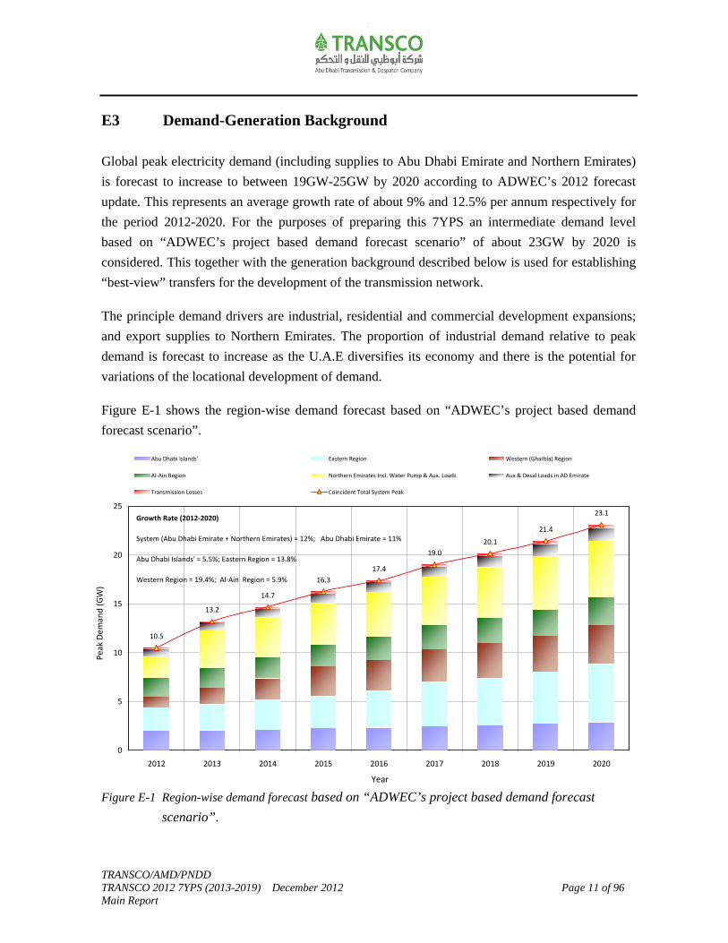
E3 Demand-Generation Background
Global peak electricity demand (including supplies to Abu Dhabi Emirate and Northern Emirates)
is forecast to increase to between 19GW-25GW by 2020 according to ADWEC’s 2012 forecast
update. This represents an average growth rate of about 9% and 12.5% per annum respectively for
the period 2012-2020. For the purposes of preparing this 7YPS an intermediate demand level
based on “ADWEC’s project based demand forecast scenario” of about 23GW by 2020 is
considered. This together with the generation background described below is used for establishing
“best-view” transfers for the development of the transmission network.
The principle demand drivers are industrial, residential and commercial development expansions;
and export supplies to Northern Emirates. The proportion of industrial demand relative to peak
demand is forecast to increase as the U.A.E diversifies its economy and there is the potential for
variations of the locational development of demand.
Figure E-1 shows the region-wise demand forecast based on “ADWEC’s project based demand
forecast scenario”.
Figure E-1 Region-wise demand forecast based on “ADWEC’s project based demand forecast
scenario”.
10.5
13.2
14.7
16.3
17.4
19.0
20.1
21.4
23.1
0
5
10
15
20
25
2012 2013 2014 2015 2016 2017 2018 2019 2020
Year
Pea
k D
em
and
(G
W)
Abu Dhabi Islands' Eastern Region Western (Gharbia) Region
Al‐Ain Region Northern Emirates Incl. Water Pump & Aux. Loads Aux & Desal Loads in AD Emirate
Transmission Losses Coincident Total System Peak
Growth Rate (2012‐2020)
System (Abu Dhabi Emirate + Northern Emirates) = 12%; Abu Dhabi Emirate = 11%
Abu Dhabi Islands' = 5.5%; Eastern Region = 13.8%
Western Region = 19.4%; Al‐Ain Region = 5.9%
TRANSCO/AMD/PNDD TRANSCO 2012 7YPS (2013-2019) December 2012 Page 12 of 96 Main Report
To meet these demands, the existing power generation plants contribute about 13.8GW (in 2012)
of capacity. New committed generation projects identified to date which are expected to be
integrated into the main bulk transmission grid in the period 2013-2020 are:
• Shams-1 concentrated solar power (CSP) plant with a maximum installed capacity of 110MW
at a facility located south of Madinat Zayed in the Western region. The plant is expected to be
commissioned after summer 2012.
• Nour-1 photovoltaic solar power (PV) plant with a maximum installed capacity of 100MW at a
facility located near Sanaiya in Al-Ain region. The plant is expected to be commissioned after
summer 2012.
• Shuweihat S3 (1.65GW) combined cycle fossil fuel plant to be located adjacent to the existing
Shuweihat S1 and S2 site in the Western region.
The first phase of Shuweihat S3 is planned to be operational (about 0.5GW capacity) in 2013
and fully operational (about 1.65GW) in 2014.
• New Mirfa (1.6GW) combined cycle fossil fuel plant to be located adjacent to the existing
Mirfa site in the Western region.
The first phase of New Mirfa plant is planned to be operational (about 0.9GW capacity) in
2015 and fully operational (about 1.6GW) in 2016.
• The Barakah site in the Western region has been identified to promote nuclear generation of
total capacity 5.6GW by 2020. Generator units of 1.4GWe each are expected to be integrated
to the transmission system through 2017-2020.
The total additional generation capacity due to above new committed generation projects
contributes about 8.9GW by 2020.
Some of the existing generation plants are expected to retire in the period 2013-2020. These are
located at Mirfa (141MW) and Madinat Zayed (108MW) in the Western region; Umn Al Nar
(778MW) in the Eastern region and Al-Ain Power Station (256MW) in Al-Ain region. The
available capacity off-set due to the closure of above existing generation will be about 1.3GW by
2020.

TRANSCO/AMD/PNDD TRANSCO 2012 7YPS (2013-2019) December 2012 Page 13 of 96 Main Report
Figure E-2 shows the expected demand-supply gap for the ADWEC’s high, project based and low
demand forecast scenarios. Certain of the demand forecasts indicate a need for additional
generation capacity from 2015 to satisfy the emerging gap between the demand and generation
outlook, and ensure sufficient generation reserve margin is available, particularly to meet the
project based and high demand forecast scenarios.
Figure E-2 Demand-supply gap in the period to 2020.
A degree of uncertainty will continue in the realization of the volume, location and timing of new
additional generation capacity in the period 2015-2020. The uncertainty levels in the demand
forecast increases (as evident from the spread between the low and high demand forecast scenario)
particularly from 2015. It should be recognized that the actual commitment to the new
conventional generation capacity takes place on a shorter time scale (about 4 years) to close any
emerging gap between the supply and demand. Options are maintained such that the associated
transmission reinforcement works are established in a phased manner to ensure minimum cost and
provide a least regret solution.
10.4
13.0
14.2
15.416.0
16.717.3
18.018.8
10.5
23.1
10.8
13.8
15.1
16.9
18.3
19.7
21.2
22.9
24.8
16.2
14.7
13.2
17.4
19.0
20.1
21.4
‐2.5
0.0
2.5
5.0
7.5
10.0
12.5
15.0
17.5
20.0
22.5
25.0
27.5
2012 2013 2014 2015 2016 2017 2018 2019 2020
Year
GW
Installed Gen Capacity (Existing) Committed Gen Capacity Proposed Gen Retirement
Low demand scenario Project based demand scenario High demand scenario
ADWEC Global Demand Forecast Growth Rate (2012‐2020)
Low demand scenario = 8.8%; Project based demand scenario = 12%; High demand scenario =12.6%
TRANSCO/AMD/PNDD TRANSCO 2012 7YPS (2013-2019) December 2012 Page 14 of 96 Main Report
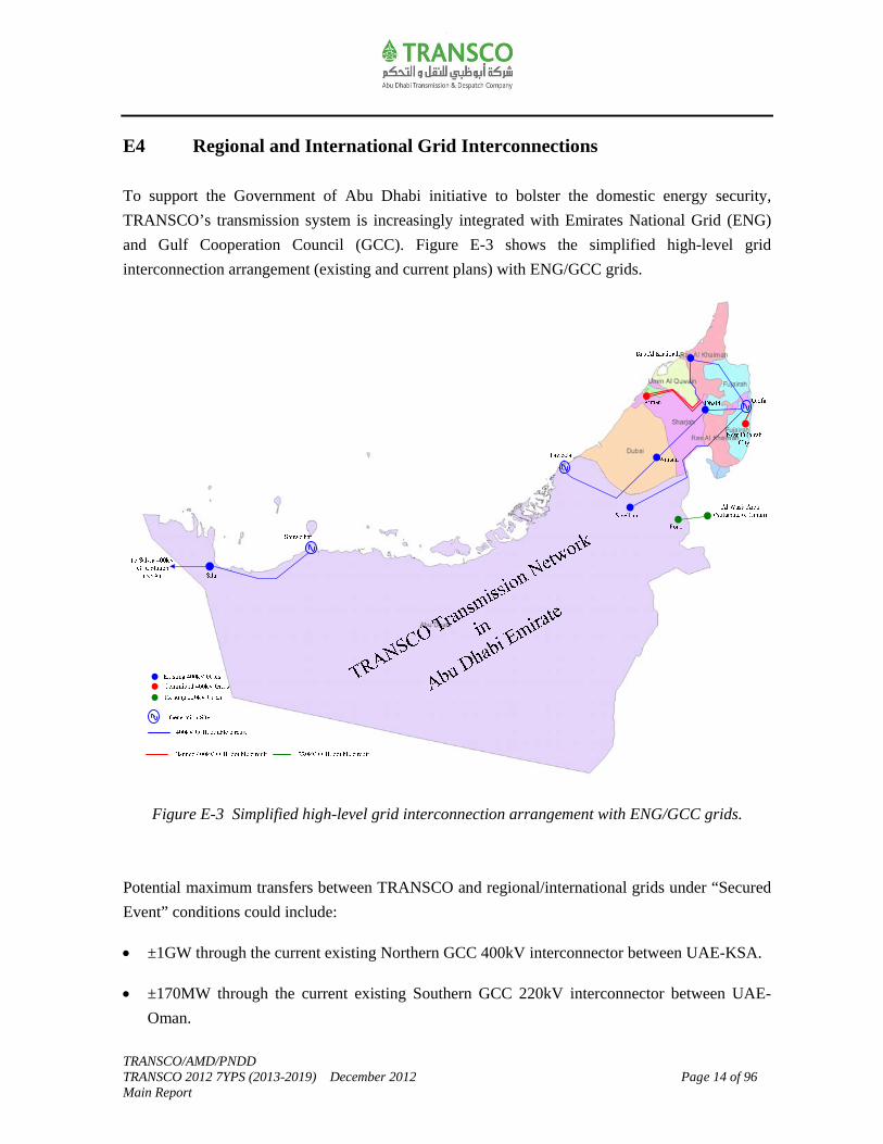
E4 Regional and International Grid Interconnections
To support the Government of Abu Dhabi initiative to bolster the domestic energy security,
TRANSCO’s transmission system is increasingly integrated with Emirates National Grid (ENG)
and Gulf Cooperation Council (GCC). Figure E-3 shows the simplified high-level grid
interconnection arrangement (existing and current plans) with ENG/GCC grids.
Figure E-3 Simplified high-level grid interconnection arrangement with ENG/GCC grids.
Potential maximum transfers between TRANSCO and regional/international grids under “Secured
Event” conditions could include:
±1GW through the current existing Northern GCC 400kV interconnector between UAE-KSA.
±170MW through the current existing Southern GCC 220kV interconnector between UAE-
Oman.
TRANSCO/AMD/PNDD TRANSCO 2012 7YPS (2013-2019) December 2012 Page 15 of 96 Main Report
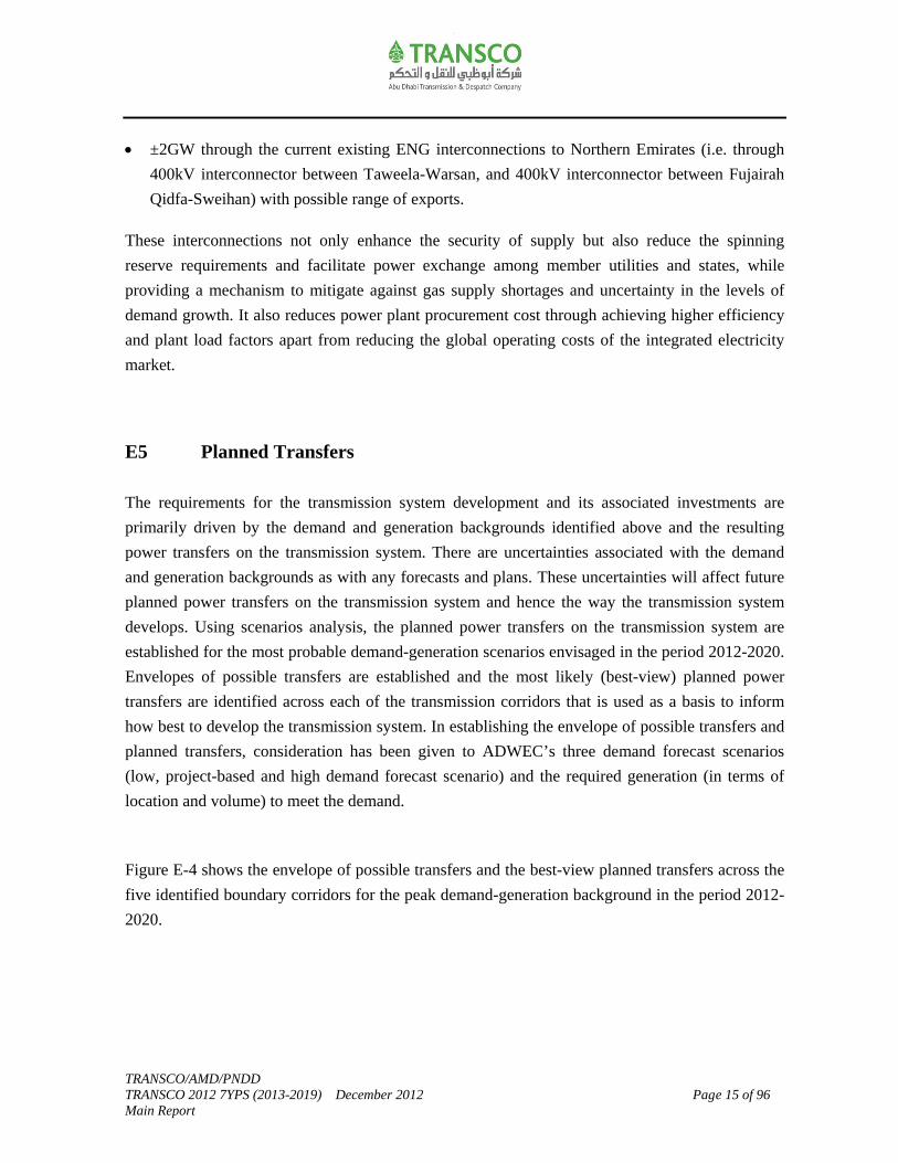
±2GW through the current existing ENG interconnections to Northern Emirates (i.e. through
400kV interconnector between Taweela-Warsan, and 400kV interconnector between Fujairah
Qidfa-Sweihan) with possible range of exports.
These interconnections not only enhance the security of supply but also reduce the spinning
reserve requirements and facilitate power exchange among member utilities and states, while
providing a mechanism to mitigate against gas supply shortages and uncertainty in the levels of
demand growth. It also reduces power plant procurement cost through achieving higher efficiency
and plant load factors apart from reducing the global operating costs of the integrated electricity
market.
E5 Planned Transfers
The requirements for the transmission system development and its associated investments are
primarily driven by the demand and generation backgrounds identified above and the resulting
power transfers on the transmission system. There are uncertainties associated with the demand
and generation backgrounds as with any forecasts and plans. These uncertainties will affect future
planned power transfers on the transmission system and hence the way the transmission system
develops. Using scenarios analysis, the planned power transfers on the transmission system are
established for the most probable demand-generation scenarios envisaged in the period 2012-2020.
Envelopes of possible transfers are established and the most likely (best-view) planned power
transfers are identified across each of the transmission corridors that is used as a basis to inform
how best to develop the transmission system. In establishing the envelope of possible transfers and
planned transfers, consideration has been given to ADWEC’s three demand forecast scenarios
(low, project-based and high demand forecast scenario) and the required generation (in terms of
location and volume) to meet the demand.
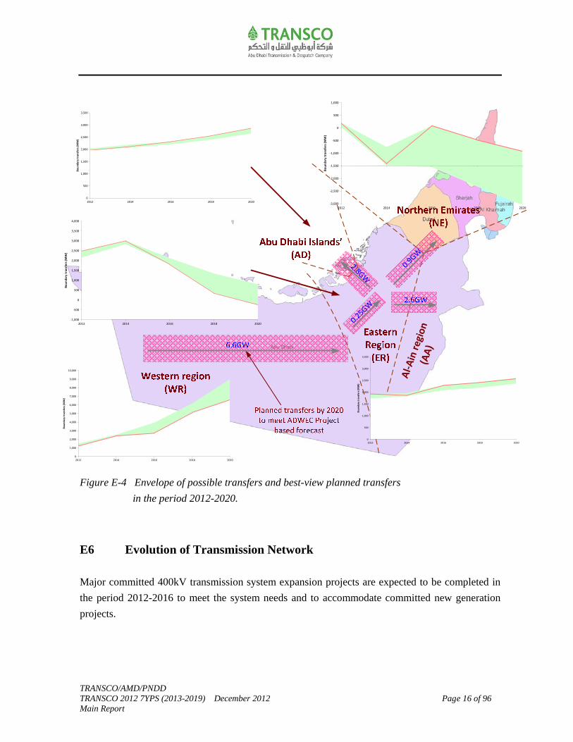
Figure E-4 shows the envelope of possible transfers and the best-view planned transfers across the
five identified boundary corridors for the peak demand-generation background in the period 2012-
2020.
TRANSCO/AMD/PNDD TRANSCO 2012 7YPS (2013-2019) December 2012 Page 16 of 96 Main Report
Figure E-4 Envelope of possible transfers and best-view planned transfers
in the period 2012-2020.
E6 Evolution of Transmission Network
Major committed 400kV transmission system expansion projects are expected to be completed in
the period 2012-2016 to meet the system needs and to accommodate committed new generation
projects.
Al‐
Ain
reg
ion
(AA
)
0
1,000
2,000
3,000
4,000
5,000
6,000
7,000
8,000
9,000
10,000
2012 2014 2016 2018 2020
Bo
un
dar
y tr
an
sfer
s (M
W)
0
500
1,000
1,500
2,000
2,500
3,000
3,500
2012 2014 2016 2018 2020
Bo
un
dar
y tr
an
sfer
s (M
W)
0
500
1,000
1,500
2,000
2,500
3,000
3,500
2012 2014 2016 2018 2020
Bo
un
dar
y tr
ansf
ers
(MW
)
‐1,000
‐500
0
500
1,000
1,500
2,000
2,500
3,000
3,500
4,000
2012 2014 2016 2018 2020
Bo
un
dar
y tr
ansf
ers
(M
W)
0.9GW
2.8GW
0.25GW
‐3,000
‐2,500
‐2,000
‐1,500
‐1,000
‐500
0
500
1,000
2012 2014 2016 2018 2020
Bo
un
dar
y tr
ansf
ers
(MW
)

TRANSCO/AMD/PNDD TRANSCO 2012 7YPS (2013-2019) December 2012 Page 17 of 96 Main Report
Figure E-5 shows the existing main bulk 400kV transmission network (as in 2012) spread across
the five regions (Western region, Eastern region, Abu Dhabi Islands’, Al-Ain region and Northern
Emirates).
Figure E-5 Existing main bulk 400kV transmission topology (as in 2012).
A network development plan has been produced based on the best view planned transfers across
the identified boundaries upto 2020.
To evacuate power from the Shuweihat S3 generation (about 1.65GW), a new 400kV grid station
(S3PS) and related 400kV overhead line transmission facilities are planned to be completed in
2013 to evacuate power from the Shuweihat S3 generation.
New 400kV grid stations and related 400kV overhead line works are expected to be integrated to
the transmission network in the period 2013-2014 to meet the respective regions’ demand
requirements. These are 400/220kV grid stations in Ruwais (RWSG) and Baab (BAAB) (in
Western region); 400/132kV grid stations in Bahia (BHYG), Mahawi (MHWG) and Shamkha
(SMKG) (in Eastern region); and 400/132kV grid stations in Ajman (AJMN) and New Fujairah
City (FJCT) in Northern Emirates.
Al‐
Ain
reg
ion
(AA
)
1.96
3.00
1.27
1.93
2.20
10.46
0
2
4
6
8
10
12
Year 2012
Pe
ak
De
man
d (G
W)
AD ER
WR AA
NE Losses
System Total
TRANSCO/AMD/PNDD TRANSCO 2012 7YPS (2013-2019) December 2012 Page 18 of 96 Main Report
Restrictions are placed by Government and developers for building new 400kV overhead lines
and/or replacing existing overhead lines within Abu Dhabi island, along Abu Dhabi island-
Sadiyat-Bahia (ADST-SDYT-BHYG) and Sas Al Nakheel-Mahawi-Mussafah (SASN-MHWG-
MOSG) corridors in the Eastern region. Hence, TRANSCO has been required to increasingly
underground transmission infrastructure serving these areas. The 400kV underground cables’
projects along the ADST-SDYT-BHYG corridor and SASN-MHWG-MOSG corridors have been
staged through 2013-2016. This is to ensure their performance will be demonstrated satisfactorily
and thereby enable the policy decision to dismantle the 400kV overhead lines along the said
corridors thereafter. The 400kV overhead line reconfiguration works between BHYG and
TANE/TWPS are staged through 2015-2016 to enable dismantling the existing 400kV overhead
line circuits along ADST-SDYT-BHYG corridor.
A new 400kV grid station (MRPS) and related 400kV overhead line transmission facilities are
planned in 2015 to evacuate power from the new Mirfa generation plant (1.6GW). The 400kV
transmission scheme for integrating new Mirfa generation at the time of writing this 7YPS is still
in the early planning stage and options are maintained for possible optimization subject to detailed
feasibility study.
A new 400kV grid station (Barakah switchyard-1) and related 400kV overhead line transmission
facilities are planned in 2015 to facilitate the start-up operations of Barakah nuclear power plant
and enable the phased integration of the nuclear power generation at Barakah. The 400kV West-
East corridor reinforcements ensure an integrated approach for evacuating power from Shuweihat
S3, Mirfa and Barakah power plants while meeting the demands in the Western region and further
oilfields.
Major 400kV transmission reinforcement’s works are required in Western region and across West-
East region corridor to evacuate power from the Barakah nuclear power plants in the period 2017-
2020. There is a need to establish two new intermediate 400kV grid stations in the Eastern region
namely Hameem (HMEM) and Al Faya (FYAG) to facilitate large volumes of power transfers
across West-East corridor; strengthen the overall 400kV transmission system and improve the
dynamic performance of the transmission network. This is achieved through major 400kV
overhead line reinforcement works between Barakah (BRKA)-Madinat Zayed (WMZD) grid
stations in the Western region; Ruwais (RWSG)-Al Faya (FYAG) grid stations in the West-East
corridor; Hameem (HMEM)-ICAD and Shamkha (SMKG)-Sweihan (SWHN) grid stations in the
Eastern region.

TRANSCO/AMD/PNDD TRANSCO 2012 7YPS (2013-2019) December 2012 Page 19 of 96 Main Report
Figure E-6 shows the evolution of the main bulk 400kV transmission in 2020.
Figure E-6 Main bulk 400kV transmission topology in 2020.
E7 Asset Replacement Works
In addition to enhancing network capacity there is a need to replace certain assets.
The requirement to replace aging assets affecting network security include:
Transformers (132/11kV transformers at EMBS/SLTC substation; and 220/33kV
transformer at Al-Ain Power Station).
Protection (busbar, line and transformer protection upgrade at various sites).
Batteries and chargers at various sites (e.g. DHMG-220, AAPS-220, AHYG-220 etc).
LV switchgear replacement at Jabel Hafeet 33kV substation.
Underground cables (replacement of oil filled to XLPE between ADST-FDRS)
Overhead lines (220kV Ruwais-Sila OPGW rehabilitation works).
Al‐
Ain
reg
ion
(AA
)
2.85
6.68
4.57
2.88
5.75
23.12
0
2
4
6
8
10
12
14
16
18
20
22
24
Year 2020
Pe
ak
De
man
d (G
W)
AD ER
WR AA
NE Losses
System Total

TRANSCO/AMD/PNDD TRANSCO 2012 7YPS (2013-2019) December 2012 Page 20 of 96 Main Report
SVC cooling and control system upgrade at AAPS, ASWG and MOSG.
Others (SCMS, FMS upgrade).
The requirement to replace/decommission aging assets affecting network security and exploit
synergies with capacity related asset creation include:
220/33kV grid stations at Mirfa, Zakher, AAPS and Al Wagon.
132kV cable circuit between Mushrif-Mussafah/Mussafah-Umn Al Nar.
The economic treatment of the assets that are expected to be decommissioned will be treated in
accordance with TRANSCO’s asset policy and shall be written off from the regulatory asset base
when disposed of after due approval from RSB.
E8 Network Operation and Despatch
The power and water demand is met by despatching production facilities in accordance with a unit
commitment model. Given the power and water system characteristics, together with the changing
characteristics particularly associated with production facilities used to meet this demand, there is
a need to ensure both power and water requirements will be securely met in an efficient manner.
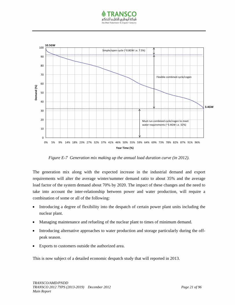
Figure E-7 shows the current generation mix making up the annual load duration curve. For the
2012, the average winter/summer demand ratio is assumed 32% and the average load factor of the
system demand about 65%.
In the period to 2020 the peak demand on the transmission network will increase from 10.5GW (in
2012) to about 19GW-25GW in 2020. This will be accompanied by a corresponding increase in
the generation portfolio. The evolution of the transmission network, expected changes in the
generation portfolio and the export requirements will significantly influence the network operation
and despatch in the period to 2020.
TRANSCO/AMD/PNDD TRANSCO 2012 7YPS (2013-2019) December 2012 Page 21 of 96 Main Report
Figure E-7 Generation mix making up the annual load duration curve (in 2012).
The generation mix along with the expected increase in the industrial demand and export
requirements will alter the average winter/summer demand ratio to about 35% and the average
load factor of the system demand about 70% by 2020. The impact of these changes and the need to
take into account the inter-relationship between power and water production, will require a
combination of some or all of the following:
Introducing a degree of flexibility into the despatch of certain power plant units including the
nuclear plant.
Managing maintenance and refueling of the nuclear plant to times of minimum demand.
Introducing alternative approaches to water production and storage particularly during the off-
peak season.
Exports to customers outside the authorized area.
This is now subject of a detailed economic despatch study that will reported in 2013.
0
10
20
30
40
50
60
70
80
90
100
0% 5% 9% 14% 18% 23% 27% 32% 37% 41% 46% 50% 55% 59% 64% 69% 73% 78% 82% 87% 91% 96%
Year Time (%)
De
man
d (
%)
3.4GW
10.5GW
Flexible combined cycle/cogen
Simple/open cycle (~0.8GW i.e. 7.5%)
Must run combined cycle/cogen to meet
water requirements (~3.4GW i.e. 32%)
TRANSCO/AMD/PNDD TRANSCO 2012 7YPS (2013-2019) December 2012 Page 22 of 96 Main Report
The main changes to the transmission network operation that TRANSCO will experience as a
result of this include fault level and reactive power management, and increased awareness of the
effects of the regional and international interconnections on the system and Users.
E9 Capital Programme and Delivery
The transmission system development requirements and associated investments are largely driven
by the demand-generation backgrounds and the resulting power transfers on the transmission
system. As there will continue to be a degree of uncertainty in the realization of the volume,
location and timing of demand-generation backgrounds in any given area, particularly in the period
2015-2020, the potential transmission reinforcement plans shall be established in a phased manner
and that the options are maintained at minimum cost to provide a least regret solution.
In view of the greater uncertainty in the development requirements; some project proposals and
schemes are evaluated with intent of optimizing the assets’ utilization taking into account the
potential risks. The risks could be if the demand does not materialize as expected or if the demand
comes early, project delays and its impact on network performance and security of supply could
result. Risk mitigation measures through various scenario/optioneering approaches are built into
the planning proposals by engaging relevant Stakeholders and Users in order to achieve a
consensus on the optimum balance of overall benefits/savings and risk trade-off. Hence, there is a
likelihood of potential deviations of some project proposals and schemes included in this 7YPS
Chapter-10 provides a high-level summary of capital and replacement projects; and a brief
description of their needs/drivers. These include the major on-going, currently under tendering
stage and new planned power projects to meet the future demands and security standard for the
period 2013-2020. Whilst some of these identified seven year capital projects shall be initiated
depending on their priority level and subject to the receipt of approvals from relevant authorities,
for others it is proposed to continue monitor the developments of the market and update the plans
accordingly.
The detailed capital delivery and capital forecast for the on-going and planned power projects to
meet the future demands and performance standards including the replacement projects are
reported separately and released only to the RSB. In that report TRANSCO have taken the
opportunity to maintain the capital delivery transparency by presenting for regulatory review a
year-on-year view of planned and delivered capital performance.
TRANSCO/AMD/PNDD TRANSCO 2012 7YPS (2013-2019) December 2012 Page 23 of 96 Report
1.0 Introduction
Condition 15 of the Transmission Licence requires Abu Dhabi Transmission and Despatch
Company (TRANSCO) to prepare a Seven Year Planning Statement (7YPS) annually in a form
approved by the Regulation and Supervision Bureau (RSB or Bureau). In relation to the electricity
transmission system, the requirement is to contain the following information in each of the seven
succeeding financial years:
a) Capacity, forecast power flows and loading on each part of the transmission system, and fault
levels for each electricity transmission node.
b) Plans for capital expenditure necessary to ensure the relevant transmission system meets the
security and performance standards and future demands.
The Sector Law requires the Abu Dhabi Water and Electricity Company (ADWEC) to prepare a
demand forecast and accordingly secure the future generation capacity to meet the short and long-
term requirements of the Sector.
The 7YPS has been developed in the context of the TRANSCO’s network development strategy
for the period to 2030 that sets out a long-term vision for taking the transmission system forward.
The network development strategy includes consideration of the trends and drivers which provides
a long-term vision for taking the transmission system forward consistent with Government’s 2030
vision. The 7YPS describes more detailed short to medium-term plans for the transmission system
and is linked to the needs and investment requirements for the period 2013-2019.
The main purpose of the 7YPS is to enable the Users seeking the use of the transmission system, to
identify and evaluate the opportunities available when connecting to and making use of such
system. Such opportunities shall be guided by the “Statement of Connection Charging
Methodology” to make a reasonable estimate of the charges to which they would be liable for the
provision of such services. It also gives a forward view on the proposed transmission infrastructure
expansion plans to meet the forecast demand growth and planned new generation capacity that will
be of benefit to other stakeholders. However, we recommend prospective Users of the system and
other stakeholders to contact TRANSCO directly if they want to fully understand the opportunities
available to them.
TRANSCO/AMD/PNDD TRANSCO 2012 7YPS (2013-2019) December 2012 Page 24 of 96 Report
This is the third 7YPS which contains the latest updated information and replaces all Statements
released earlier. This 7YPS covers the planning period 2013-2019. It also covers the planning
horizon 2020 to assess the impact of all four Barakah nuclear reactors on the main bulk 400kV
power transmission system developments. 2012 7YPS (2013-2019) is based on the best available
updated information from ADWEC and Users; updated project scope and status. The cutoff date
for input data is 30 April 2012.
The 2012 7YPS (2013-2019) draft version was released in June 2012. Subsequently, the structure
and content of the draft statement was revised after due agreement with RSB (in December 2012)
acceptable for release in the public domain. It was also agreed with RSB to provide an update on
some of the changes in the project proposals between the release of the draft version and the issue
of this updated version. These are as follows:
a) Project proposals which have been cancelled/put on hold are:
400/220kV grid station in Wasit (Oman) and related 400kV overhead line works.
400/132kV grid station in Sharjah and related 400kV overhead line works.
400kV reactor works at Beach (E48) 400/132kV grid station.
132kV cable interconnection works between Reem Island and Abu Dhabi Island.
b) Project proposal wherein the scheme has undergone some changes:
400kV overhead line works as part of Mirfa power plant integration with the transmission network.
c) Preliminary project proposals which require further detailed study particularly where the
developments are towards the end of the planning period included in this 7YPS are:
400/220kV grid station and related 400kV overhead line works in Al-Ain region.
400/132kV grid station and related 400kV cable works in Abu Dhabi island.
The study results could potentially influence their final scheme configuration.
The above updates and other new requirements received after the cutoff date will be updated in
2013 7YPS (2014-2020).
The 7YPS presents a wide range of information relating to the planning and development of
400kV, 220kV and 132kV transmission system within the Emirate of Abu Dhabi and, where
appropriate, TRANSCO network outside of the authorized area.

TRANSCO/AMD/PNDD TRANSCO 2012 7YPS (2013-2019) December 2012 Page 25 of 96 Report
The 7YPS update contains the following chapters:
a) Network development strategy
The network development strategy for the period to 2030 sets a long-term vision for taking the
transmission system forward. It places much greater emphasis on the trends and drivers which
provides a long-term vision for taking the transmission system forward consistent with
Government’s 2030 vision.
b) Demand-generation background
The requirement for the transmission system development and its associated investments is
primarily driven by the demand and generation backgrounds. The demand-generation trends and
the choice of the key assumptions are summarized. Based on the electrical connectivity and
geographical dispersion, the capacity and demand forecast at each part of the transmission network
are presented.
c) Planned transfers
In this chapter the envelope of possible transfers and the best-view planned transfers based on the
demand-generation backgrounds are summarized. These planned transfers determine the
requirements for the transmission system developments and its associated investment plans.
d) Evolution of transmission network
The evolution of 400kV, 220kV and 132kV transmission system within the Emirate of Abu Dhabi
and, where appropriate, the TRANSCO network outside of the authorized area up to 2020 are
presented. The evolution of the transmission network is based on the best-view planned transfers.
e) Asset replacement works
The requirements to replace aging assets affecting network security is included. While identifying
these requirements considerations have been given to exploit the synergies with capacity related
asset creation.
TRANSCO/AMD/PNDD TRANSCO 2012 7YPS (2013-2019) December 2012 Page 26 of 96 Report
f) Network operation and despatch
The evolution of the transmission network to meet the demand-generation background and the
expected changes in the generation portfolio and export requirements will significantly influence
the network operation and despatch in the period to 2020. In this chapter, the changes to the
generation portfolio and its impact on the despatch; and the potential changes to the transmission
system operational requirements is briefly described.
g) Transmission system capabilities and constraints
This chapter describes the main bulk transmission system capabilities which give an indication of
the extent to which the system can accommodate the circumstances outside the chosen likely best
view planned transfers. It also provides an insight into some of the major constraints in the
transmission network and at the Users interfaces, so that the Users can evaluate its impact on their
network.
h) Opportunities
The potential generation and transmission connection opportunities are presented. The ability to
connect new connections that requires the least electricity transmission reinforcement works is the
main consideration given for the purpose of identifying the opportunities.
i) Capital programme and delivery
The chapter summarizes the on-going projects and planned proposals to meet the future demands
and comply with security standard. It also includes a brief description of the needs/drivers for the
identified projects/proposals among other information.
TRANSCO/AMD/PNDD TRANSCO 2012 7YPS (2013-2019) December 2012 Page 27 of 96 Report
2.0 Network Development Strategy
TRANSCO has over the years developed a modern and reliable transmission system making use of
best available technology to provide a high degree of energy security. TRANSCO aims to continue
to develop, operate and maintain a safe, flexible, accessible, robust, reliable, and efficient
transmission system that meets the needs of its customers in a manner consistent with its License
obligations. This is to be achieved through a structured asset management process that takes
cognizance of best practice asset management principles for the development and stewardship of
the transmission network and requirements for capital assurance governance.
TRANSCO’s power network development strategy for the period to 2030 provides a long-term
vision for taking the transmission system forward and provides direction to the 7YPS and its
associated investment plans. The strategy places much greater emphasis on the trends and drivers
which provides a long-term vision for taking the transmission system forward consistent with
Government’s 2030 vision. The 7YPS describes more detailed short to medium-term plans for the
transmission system and is linked to the needs/investment requirements in the period 2013-2019.
2.1 Challenges
Over the period to 2030 the development of the transmission system will face many challenges.
High levels of projected future demand growth along with changing customer and social needs that
influence the location and timing of demand development will require greater participation and
active engagement with customers. Meanwhile, there are uncertainties in the future primary
generation energy mix and associated demand-generation backgrounds. There is a need to manage
these uncertainties and reduce the risk in making investment decisions, while limiting if not
avoiding congestion on the transmission system. Efforts to mitigate the effects of global climate
change combined with a shortage of domestic gas will encourage promoting low-carbon and
sustainable generation resources (including renewable sources), energy storage, demand side
management and other forms of energy sources. While the transmission network is comparatively
young, there is a need to ensure that the requirements for assets approaching the end of their useful
lives are managed and replaced at an appropriate time. These replacements shall be programmed
and managed innovatively to better position the transmission network for next 20 years of
operation and maintenance. All these require greater understanding and managing the technical
challenges, and thereby create opportunities for integrating new technologies, operation and
maintenance practices that are now available particularly in primary transmission equipment, and
information and communication technology.
TRANSCO/AMD/PNDD TRANSCO 2012 7YPS (2013-2019) December 2012 Page 28 of 96 Report
2.2 Objectives
The long-term network development strategy for the period to 2030 (20 years) aims to provide an
optimized vision for taking the transmission system forward that takes into account the
government objectives and policies, particularly those associated with the United Arab Emirates
(UAE) future social, environmental and economic requirements. The Abu Dhabi Economic Vision
2030 envisaged a real Gross Domestic Product (GDP) average target growth rate of about 6.4%
per annum for the period 2010-2030. The Abu Dhabi Urban Planning Council (UPC) developed
the “Plan Abu Dhabi 2030-Urban Structure Framework Plan” calibrated to achieve the target
population growth rate at about 4.8% for the period 2010-2030. The electricity transmission
infrastructure continues to be developed consistent with the above set policy targets among others
to support the future economic development of the Abu Dhabi Emirate.
The adopted transmission network development strategy along with the application of relevant
novel technologies will ensure achieving the following objectives:
Fulfill the expectations of society.
Facilitate sufficient energy resources to meet the current and future demand within the Emirate and to allow Abu Dhabi’s continued contribution to the energy requirements of the UAE.
Secure the domestic energy supplies to minimize vulnerabilities associated with unplanned domestic system disruptions, import disruptions, and other crises.
Provide accessibility in granting connection access to all network users and benefits to customers at the earliest opportunity, particularly for renewable power sources and high efficiency local generation with zero or low carbon emissions.
Reliable in assuring and improving the security of supply standards, transmission code and quality of supply to accommodate the customer requirements having different technical characteristics.
Economical by providing the best value through innovation and efficient energy management while supporting economic competitiveness and diversification by facilitating supply of reasonably priced energy and tariff regulations.
Facilitate implementation of Abu Dhabi Water and Electricity Authority (ADWEA) Demand Side Management (DSM) program. This program presents policies, means and techniques to achieve a scale of possible reduction of electricity demand keeping high standards of living and customer satisfaction.
TRANSCO/AMD/PNDD TRANSCO 2012 7YPS (2013-2019) December 2012 Page 29 of 96 Report
Flexible in fulfilling the customers’ needs and broader spectrum of stakeholders whilst responding to the changes and challenges ahead.
Environmentally friendly and safe. Protect the environment by facilitating renewable and alternative energy technologies, mitigating the negative effects of traditional energy production, and achieving increased energy efficiency among consumers within the Emirate. The target renewable energy share is set at 7% by 2020.
Reduce uncertainty and risk to investment decisions.
Ensure end of life renewal of assets for sustainable operation of the grid.
2.3 Principle Long-Term Drivers and Trends
The principle drivers and trends which will shape the long-term development of the power
transmission system and the investment plans and thereby achieve the above objectives with
improved transmission performance are:
a) Electricity demand
Electricity is the critical enabler for the economic and social development of the UAE.
Peak electricity demand (including supplies to Abu Dhabi Emirate and Northern Emirates) is
forecast to increase from 8.5GW (in 2010) to about 33.5GW by 2030 according to ADWEC’s
2012 forecast update. Figure 2-1 shows the historical and forecast electricity demand up to 2030.
ADWEC 2012 forecast update produced other possible demand forecast scenarios upto 2020 to
capture the uncertainty in the forecast variables and economic environment. The long-term
network development strategy and 7YPS is based on “ADWEC project based demand forecast
scenario” which is considered to be their best-view demand forecast trajectory.
The principle demand drivers are industrial expansion; new mega residential and commercial
developments; and export supplies to Northern Emirates. The proportion of industrial demand
relative to peak demand is forecast to increase as the Abu Dhabi diversifies its economy.

TRANSCO/AMD/PNDD TRANSCO 2012 7YPS (2013-2019) December 2012 Page 30 of 96 Report
Figure 2-1 Historical and forecast electricity demand.
Source: GDP data from Ministry of Economy Website (from 2001-2006) & Abu Dhabi Economic Vision 2030 (from 2006-2030). Demand data from ADWEC received in February 2012.
b) Regional and international grid interconnections
To support the Government of Abu Dhabi initiative to bolster the domestic energy security,
TRANSCO’s transmission system will increasingly integrate with Emirates National Grid (ENG)
and Gulf Cooperation Council (GCC) transmission system. Figure 2-2 shows the simplified high-
level grid interconnection arrangement (existing and current plans) with ENG/GCC grids.
Potential maximum transfers between TRANSCO and regional/international grids under “Secured
Event” conditions could include:
±1GW through the existing Northern GCC 400kV interconnector between UAE-KSA.
±170MW through the existing Southern GCC 220kV interconnector between UAE-Oman.
±2GW through the existing ENG interconnections to Northern Emirates (i.e. through 400kV
interconnector between Taweela-Warsan, and 400kV interconnector between Fujairah Qidfa-
Sweihan) with possible range of exports.
0
50
100
150
200
250
300
350
400
450
500
2000 2002 2004 2006 2008 2010 2012 2014 2016 2018 2020 2022 2024 2026 2028 2030
Year
GD
P ‐ U
S $ b
illio
n
0
5
10
15
20
25
30
35
40
45
Pea
k D
em
and (
GW
)
Real GDP ADWEC Project based demand forecast scenario
Real GDP Growth Rate: 2000‐2010: 11.4% (Actual); 2010‐2030: 6.4% (Forecast)
ADWEC Demand Growth Rate: 2000‐2010: 9.8% (Actual); 2010‐2030: 7.1% (Forecast)

TRANSCO/AMD/PNDD TRANSCO 2012 7YPS (2013-2019) December 2012 Page 31 of 96 Report
Figure 2-2 Simplified high-level grid interconnection arrangement with ENG/GCC grids.
These interconnections will not only enhance the security of supply but also reduce the spinning
reserve requirements and facilitate power exchange among member utilities and states, while
providing a mechanism to mitigate against the potential gas supply shortages and uncertainty in the
levels of demand growth. It will also reduce plant procurement cost through achieving higher
efficiency and plant load factors apart from reducing the global operating costs of the integrated
electricity market.
c) Generation capacity trend
The production of electricity and the desalinated water are dominated by large-scale operators
using conventional technologies such as gas turbines and thermal desalination. Figure 2-3 shows
the historical and future demand-generation trend upto 2030. A degree of uncertainty will continue in
the realization of the volume, location and timing of new generation plants beyond 2015. The actual
commitment and completion of new generation plants and related transmission reinforcement works take
place on a shorter time scale (about 4 years) to close the emerging gap in the capacity deficit and based on
the year-on-year updated short-term best-view demand forecast trajectory.
TRANSCO/AMD/PNDD TRANSCO 2012 7YPS (2013-2019) December 2012 Page 32 of 96 Report
Figure 2-3 Demand-generation trend in the period 2000-2030.
To support the Government objectives of achieving energy sufficiency, energy security, economic
diversification, and reduce the negative environmental impact of fossil fuel generation within the
Emirate, connection of essential new generation such as nuclear and renewable are planned which
have different technical characteristics to the current generation portfolio.
The target of the Government’s objective is not to displace the existing or future fossil fuel plants,
but to supplement them with a diverse mix of technologies and fuel sources that make the
electricity sector less vulnerable to supply interruptions, market swings, and other crises while
creating the commercial impetus for the emergence of new technology-based clusters within the
local economy. This has required consideration of:
Committed new generation expansion projects.
ADWEC’s view on the future potential capacity and their potential site locations as outlined in
their 2011 Statement of Future Capacity Requirements.
Closures of some existing generating plants due to various legislation and age profile.
Policy drivers on renewable energy targets (objective is to drive towards establishing a 7%
share of renewable energy by 2020) and demand side management initiatives.
Adequate generation resources to maintain sufficient reserve margin.
3.3 4.0 4.35.6
6.6
8.5
10.5
14.7
17.4
20.1
23.1
25.4
27.6
29.5
31.6
33.7
‐5
0
5
10
15
20
25
30
35
40
2000 2002 2004 2006 2008 2010 2012 2014 2016 2018 2020 2022 2024 2026 2028 2030
Year
GW
Installed Gen Capacity (Existing) Committed Gen Capacity
Proposed Gen Retirement ADWEC Project based demand forecast scenario
Actual Forecast
TRANSCO/AMD/PNDD TRANSCO 2012 7YPS (2013-2019) December 2012 Page 33 of 96 Report
d) Technological developments
Technologies such as higher rating overhead line conductors for increased power transfers,
increased use of XLPE cables in areas of high amenity value at voltages up to 400kV, adoption of
765kV or HVDC transmission voltage levels and the application of static and dynamic reactive
power compensators, while not necessarily new technologies require consideration in the
transmission system development.
Elsewhere in the world, considerable attention is being paid to so-called “smart grids” to aid in
integrating renewable, changing customer requirements and renewing life expired assets. Whilst
not necessarily directly applicable to the UAE, some potential technologies such as the application
of smart meters in the selective areas of the distribution network within the Abu Dhabi Emirate
have been considered.
From a transmission perspective, the smart grid components could essentially include and integrate
synchrophasor measurement, intelligent protection schemes, power flow control, static var
compensation, real time monitoring, energy storage management and solar/wind forecasting tools,
advanced metering (AMR), demand response, energy storage devices, condition monitoring,
control and decision support systems. These requires massive changes in the electrical system and
the way it should be structured and operated, which has the potential to create a new system
architecture.
e) System operation and despatch
The generation mix and demand side technologies along with the changes expected in the load
duration curve due to high industrial demand growth and export requirements will required to be
considered. These are likely to alter the summer-winter peak demand ratio to about 35% and the
average load factor of the system demand about 70% by 2020. The impact of these changes,
particularly the need to take into account the inter-relationship between power and water
production, could lead to the need to introduce other methods of water production such as reverse
osmosis (RO) and opportunities for energy storage. As a result the intermittency and non-
despatchable plant characteristics of wind and solar generation, and plans to despatch nuclear plant
as base load and/or introduce degree of flexibility in their operation needs to be considered.
TRANSCO/AMD/PNDD TRANSCO 2012 7YPS (2013-2019) December 2012 Page 34 of 96 Report
f) Asset replacement
While the transmission network is comparatively young, there will be requirements for assets
approaching the end of their useful lives to be managed and replaced at an appropriate time. Asset
Management process improvements will be required to capture the “knowledge to build only what
is needed”. Integrated outage management and risk assessment need to be considered for improved
operational efficiency. Maintenance practices and resource management processes shall be
programmed and managed innovatively to better position the transmission network for next 20
years of operation and maintenance; particularly noting that the system demand develops from
about 8.5GW (in 2010) to about 33.5GW (in 2030). Certain of these can be managed by
technologies mentioned above. All these improvements will enable reduction in the utility costs
(CAPEX and OPEX) resulting in optimized asset utilization and efficient operation.
g) Standards and procedures
The evolution of bulk transmission network over the period to 2030 requires review of standards
and procedures related to the network operation and despatch that needs to address:
System complexity as the network develops to meet the demand requirements of 2030.
Operational connection topology to manage fault levels within acceptable limits.
Levels of security (infeed risk), power factor, reactive power management, stability including
fault ride through and frequency response, and spinning reserve issues.
Power quality requirements of customers and sensitive loads.
2.4 Approach to Developing the Main Bulk Transmission System
The requirements for the transmission system development and its associated investments are
primarily driven by the demand and generation backgrounds and the resulting power transfers on
the transmission system. There are uncertainties associated with the demand and generation
backgrounds as with any forecasts and plans. These uncertainties will affect future planned power
transfers on the transmission system and hence the way the transmission system develops.
To manage the uncertainties, the approach adopted in this strategy is based on the “scenario
analysis” taking into account the sensitivities, constraints and risks through considering:
TRANSCO/AMD/PNDD TRANSCO 2012 7YPS (2013-2019) December 2012 Page 35 of 96 Report
Different demand forecast scenarios in the range 22GW-40GW by 2030.
Considering different locational development of demand including different levels of transfers
to the Northern Emirates.
Different locational development of generation to meet the above demands.
Using the scenarios developed, the planned power transfers on the transmission system are
established for various demand-generation scenarios. Given the differences in scenarios, envelopes
of possible transfers are established. The scenario analysis establishes the most likely (best-view)
planned power transfers across each of the identified transmission corridors that is used as a basis
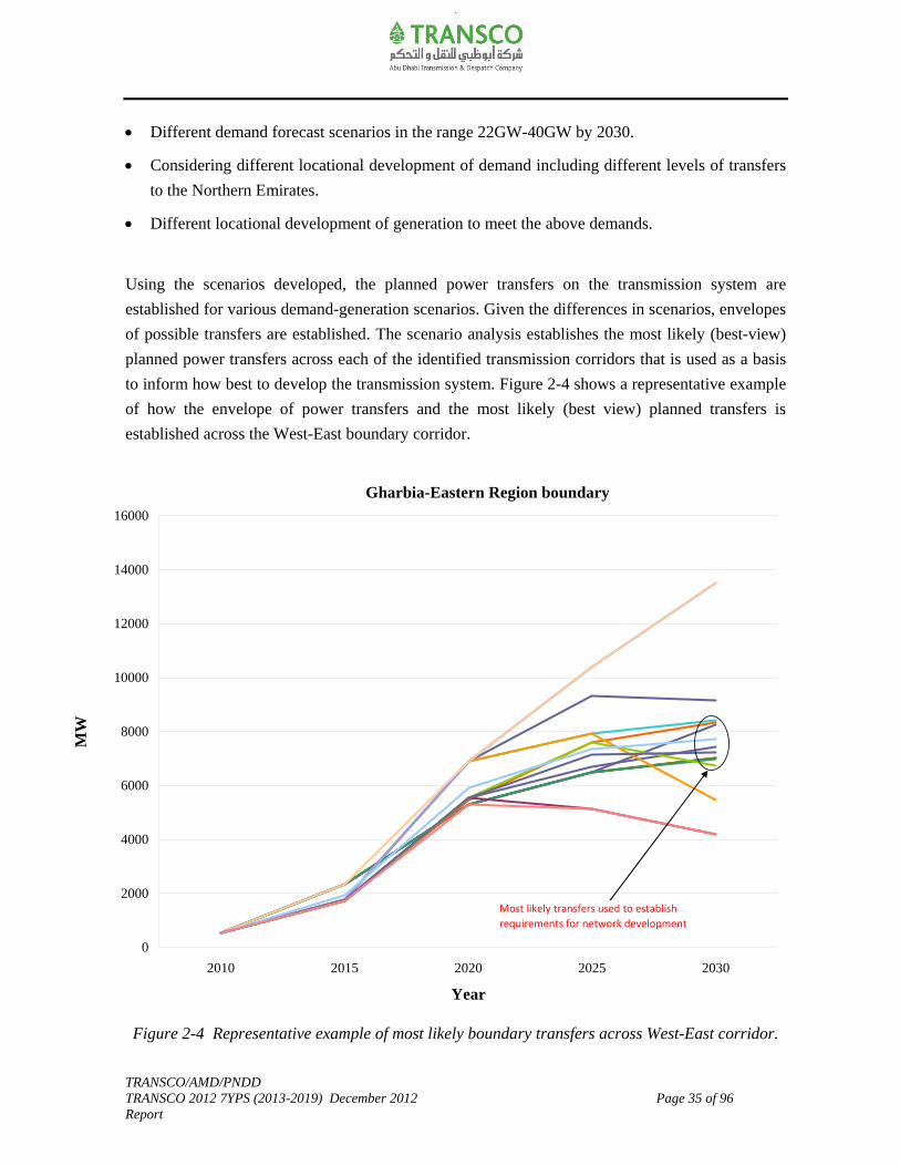
to inform how best to develop the transmission system. Figure 2-4 shows a representative example
of how the envelope of power transfers and the most likely (best view) planned transfers is
established across the West-East boundary corridor.
Figure 2-4 Representative example of most likely boundary transfers across West-East corridor.
Gharbia-Eastern Region boundary
0
2000
4000
6000
8000
10000
12000
14000
16000
2010 2015 2020 2025 2030
Year
MW
Most likely transfers used to establish
requirements for network development
TRANSCO/AMD/PNDD TRANSCO 2012 7YPS (2013-2019) December 2012 Page 36 of 96 Report
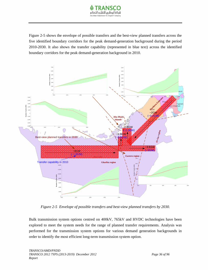
Figure 2-5 shows the envelope of possible transfers and the best-view planned transfers across the
five identified boundary corridors for the peak demand-generation background during the period
2010-2030. It also shows the transfer capability (represented in blue text) across the identified
boundary corridors for the peak demand-generation background in 2010.
Figure 2-5 Envelope of possible transfers and best-view planned transfers by 2030.
Bulk transmission system options centred on 400kV, 765kV and HVDC technologies have been
explored to meet the system needs for the range of planned transfer requirements. Analysis was
performed for the transmission system options for various demand generation backgrounds in
order to identify the most efficient long-term transmission system option.
-2,000
-1,000
0
1,000
2,000
3,000
4,000
5,000
6,000
2010 2015 2020 2025 2030
Bou
nda
ry T
ran
sfer
s (M
W)
~8GW(~1.8GW)
~5GW(~2.2GW)
~3.5GW(~2GW)
~1.5GW(~3.2GW)
~2GW(~0.3GW)
Best-view planned transfers in 2030
Gharbia region
North
ern E
mira
tes
Abu Dhabi Islands’
Eastern region
0
2,000
4,000
6,000
8,000
10,000
12,000
14,000
2010 2015 2020 2025 2030
Bou
ndar
y T
rans
fers
(M
W)
0
1,000
2,000
3,000
4,000
5,000
2010 2015 2020 2025 2030
Bou
nd
ary
Tra
nsf
ers
(MW
)
0
1,000
2,000
3,000
4,000
5,000
6,000
7,000
2010 2015 2020 2025 2030
Bou
nd
ary
Tra
nsf
ers
(MW
)
-4,000
-3,000
-2,000
-1,000
0
1,000
2,000
3,000
4,000
5,000
2010 2015 2020 2025 2030
Bou
nd
ary
Tra
nsf
ers
(MW
)
-2,000
-1,000
0
1,000
2,000
3,000
4,000
5,000
6,000
2010 2015 2020 2025 2030
Bou
nd
ary
Tra
nsf
ers
(MW
)
Transfer capability in 2010
TRANSCO/AMD/PNDD TRANSCO 2012 7YPS (2013-2019) December 2012 Page 37 of 96 Report
400kV is chosen as the most likely transmission system option to ensure that the investments are
economical and efficient and that those Users connecting to the system can reasonably identify and
evaluate opportunities. As there will continue to be a degree of uncertainty in the realization of the
volume, location and timing of demand and generation backgrounds in any given area, it is
proposed to continue to monitor the developments of the market and update the scenarios
accordingly. Hence, the potential transmission reinforcement plans shall be established in a phased
manner and that the options are maintained at minimum cost to provide a least regret solution.
It should be noted that the 400kV transmission reinforcements associated with the 1st and 2nd
Barakah nuclear units are able to exploit the synergies with the committed transmission network
associated with Shuweihat S3 generation integration. Migration to 765kVAC or HVDC as the
main overlay transmission system option over the existing 400kV network across the West-East
corridor is convincing only if significant future generation is introduced in the Western region and
that the Abu Dhabi has increased obligations to meet the demand requirements in Northern
Emirates to achieve transmission distance of about 400km or more. In developing the transmission
system, considerations have also been given to the increasing requirements for renewal of existing
assets in the period to 2030.
2.5 Summary
TRANSCO’s network development strategy is to continue to develop a flexible, reliable, secure,
accessible, robust, economical, efficient, environmentally friendly and safe transmission system
that meets the needs of its customers in a manner consistent with its Licence obligations.
This is achieved through:
Implementing a structured asset management process that takes cognizance of best practice
asset management principles for the development and stewardship of the transmission network
and requirements for capital assurance governance.
Continuing with the development of 400kV main bulk transmission system. Given the
uncertainty in the demand and generation background, the possible need to migrate to 765kV
or HVDC as the main overlay transmission system option across the West-East corridor is to
be kept under review, particularly if significant levels of additional generation capacity are
contracted in the Western region, and that there is increased requirement to provide power to
Northern Emirates.
TRANSCO/AMD/PNDD TRANSCO 2012 7YPS (2013-2019) December 2012 Page 38 of 96 Report
Replacement of assets whose condition is approaching end of useful life in a manner that
avoids adversely affecting network security and exploits any synergies with capacity related
asset creation.
Incremental deployment and integration of new technologies and best available practice.
It is intended that the development of the transmission network will be done in such a manner to:
Have minimum negative side-effects on the environment and society.
Accommodate large central and decentralized generation.
Enable active participation of consumers including demand response.
Provide high quality of supply and reliable power that satisfy the expectation and needs of the
customer and comply with international best practice and standards.
Optimize asset utilization and operate efficiently through integrated outage management, risk
assessment, improved process, resource management and use of technology and decision
support tools.
Anticipate and respond to system disturbances.
Operate resiliently under unforeseen events.

TRANSCO/AMD/PNDD TRANSCO 2012 7YPS (2013-2019) December 2012 Page 39 of 96 Report
3.0 Demand-Generation Background
The Sector Law requires ADWEC to prepare a demand forecast and accordingly secure the future
generation capacity to meet the short and long-term requirements of the Sector. The requirement
for the transmission system development and its associated investments is primarily driven by the
demand and generation backgrounds. In this chapter, the demand-generation trends and the choice
of the key assumptions are summarized. Based on the electrical connectivity and geographical
dispersion, the capacity and demand forecast at each part of the transmission network are
highlighted.
3.1 Demand Background
In 2010 the total global system peak demand recorded was about 8.5GW, which included supplies
to the Abu Dhabi Emirate and the Northern Emirates. In 2011 the total global system peak demand
recorded 9.8GW. Historically, the electricity peak demand sustained an average growth of 9.8%
for the period 2000-2010. The average peak demand growth for the Abu Dhabi Emirate was 7.8%
for the same period. In 2006 TRANSCO established interconnection with Emirates National Grid
(ENG) with the intention of supporting the member utilities of the U.A.E.
ADWEC’s 2012 forecast update produced three demand forecast scenarios (low, project based and
high forecast scenarios) upto 2020 to capture the uncertainty and market volatility in the economic
environment. This 7YPS is based on “ADWEC project based demand forecast scenario” which is
considered to be their best-view demand forecast.
The ADWEC project based forecast scenario is intended to cater for the generation plant capacity
building and for guiding the expansion of the power transmission system. This is with maintaining
the flexibility to accommodate among the other scenarios as necessary (as per the ensuing changes
in the economic environment).
Figure 3-1 shows ADWEC demand forecast upto 2020.

TRANSCO/AMD/PNDD TRANSCO 2012 7YPS (2013-2019) December 2012 Page 40 of 96 Report
Figure 3-1 ADWEC demand forecast upto 2020.
Global peak electricity demand (include supplies to Abu Dhabi Emirate and Northern Emirates) is
forecast to increase between 19GW-25GW by 2020 according to ADWEC’s 2012 forecast update.
This represents an average growth rate of about 9% and 12.5% per annum respectively for the
period 2012-2020.
For the project based forecast scenario, the global peak electricity demand is forecast to increase
from about 10.5GW (in 2012) to about 23GW by 2020. This represents an average growth rate of
about 12% per annum for the period 2012-2020.
In developing the demand forecast, the updated Users demand forecast data, demand notifications
from mega residential/ commercial project developers, bulk industrial consumers demand data,
population growth, economic activity and export requirements are captured based on ADWEC’s
analysis.
The principle demand drivers are industrial, residential and commercial development expansions;
and export supplies to Northern Emirates. The proportion of industrial demand relative to peak
demand is forecast to increase as the Abu Dhabi diversifies its economy and there is the potential
for variations of the locational development of demand within the outlier demand scenario.
10.4
13.0
14.2
15.416.0
16.717.3
18.018.8
10.5
23.1
10.8
13.8
15.1
16.9
18.3
19.7
21.2
22.9
24.8
16.2
14.7
13.2
17.4
19.0
20.1
21.4
0.0
2.5
5.0
7.5
10.0
12.5
15.0
17.5
20.0
22.5
25.0
27.5
2012 2013 2014 2015 2016 2017 2018 2019 2020
Year
GW
Low demand scenario Project based demand scenario High demand scenario
ADWEC Global Demand Forecast Growth Rate (2012‐2020)
Low demand scenario = 8.8%; Project based demand scenario = 12%;
High demand scenario =12.6%

TRANSCO/AMD/PNDD TRANSCO 2012 7YPS (2013-2019) December 2012 Page 41 of 96 Report
Figure 3-2 and Table 3-1 shows the region-wise forecast for the project based demand forecast
scenario. The Attachment-A contains the full details of the region-wise forecast (project based
forecast scenario) showing the existing and future capacity; and peak demand forecast at the exit
demand supply points for the period 2012-2020.
Figure 3-2 Region-wise demand forecast for the project based forecast scenario.
Further details relating to the demand forecast are included in the Attachment-A as follows:
Table A2 includes a summary of the region-wise peak demand forecast for the project
based forecast scenario.
Table A3 includes the capacity, estimated power factor and peak demand forecast at the
grid supply points. It also includes the expected utilization at the grid supply points in
2020.
Table A4 includes the capacity, power factor and peak demand forecast at the exit demand
supply points in Abu Dhabi Emirate. It also includes the expected utilization at the exit
demand supply points in 2020.
Table A5 includes the capacity and assumed peak demand forecast at the 400kV grid
supply points corresponding to the export commitments to Northern Emirates.
10.5
13.2
14.7
16.3
17.4
19.0
20.1
21.4
23.1
0
5
10
15
20
25
2012 2013 2014 2015 2016 2017 2018 2019 2020
Year
Pea
k D
em
and (
GW
)
Abu Dhabi Islands' Eastern Region Western (Gharbia) Region
Al‐Ain Region Northern Emirates Incl. Water Pump & Aux. Loads Aux & Desal Loads in AD Emirate
Transmission Losses Coincident Total System Peak
Growth Rate (2012‐2020)
System (Abu Dhabi Emirate + Northern Emirates) = 12%; Abu Dhabi Emirate = 11%
Abu Dhabi Islands' = 5.5%; Eastern Region = 13.8%
Western Region = 19.4%; Al‐Ain Region = 5.9%
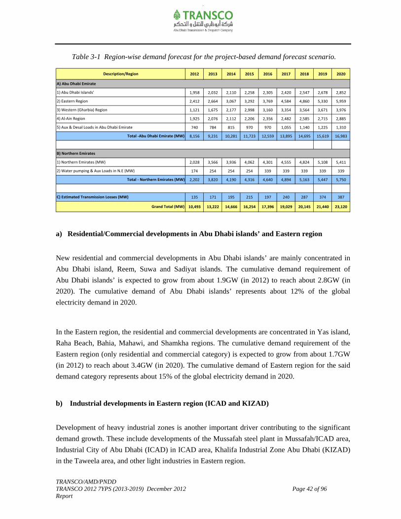
TRANSCO/AMD/PNDD TRANSCO 2012 7YPS (2013-2019) December 2012 Page 42 of 96 Report
Table 3-1 Region-wise demand forecast for the project-based demand forecast scenario.
a) Residential/Commercial developments in Abu Dhabi islands’ and Eastern region
New residential and commercial developments in Abu Dhabi islands’ are mainly concentrated in
Abu Dhabi island, Reem, Suwa and Sadiyat islands. The cumulative demand requirement of
Abu Dhabi islands’ is expected to grow from about 1.9GW (in 2012) to reach about 2.8GW (in
2020). The cumulative demand of Abu Dhabi islands’ represents about 12% of the global
electricity demand in 2020.
In the Eastern region, the residential and commercial developments are concentrated in Yas island,
Raha Beach, Bahia, Mahawi, and Shamkha regions. The cumulative demand requirement of the
Eastern region (only residential and commercial category) is expected to grow from about 1.7GW
(in 2012) to reach about 3.4GW (in 2020). The cumulative demand of Eastern region for the said
demand category represents about 15% of the global electricity demand in 2020.
b) Industrial developments in Eastern region (ICAD and KIZAD)
Development of heavy industrial zones is another important driver contributing to the significant
demand growth. These include developments of the Mussafah steel plant in Mussafah/ICAD area,
Industrial City of Abu Dhabi (ICAD) in ICAD area, Khalifa Industrial Zone Abu Dhabi (KIZAD)
in the Taweela area, and other light industries in Eastern region.
2012 2013 2014 2015 2016 2017 2018 2019 2020
1,958 2,032 2,110 2,258 2,305 2,420 2,547 2,678 2,852
2,412 2,664 3,067 3,292 3,769 4,584 4,860 5,330 5,959
1,121 1,675 2,177 2,998 3,160 3,354 3,564 3,671 3,976
1,925 2,076 2,112 2,206 2,356 2,482 2,585 2,715 2,885
740 784 815 970 970 1,055 1,140 1,225 1,310
8,156 9,231 10,281 11,723 12,559 13,895 14,695 15,619 16,983
2,028 3,566 3,936 4,062 4,301 4,555 4,824 5,108 5,411
174 254 254 254 339 339 339 339 339
2,202 3,820 4,190 4,316 4,640 4,894 5,163 5,447 5,750
135 171 195 215 197 240 287 374 387
10,493 13,222 14,666 16,254 17,396 19,029 20,145 21,440 23,120
C) Estimated Transmission Losses (MW)
Grand Total (MW)
A) Abu Dhabi Emirate
B) Northern Emirates
1) Northern Emirates (MW)
2) Water pumping & Aux Loads in N.E (MW)
2) Eastern Region
Total ‐ Northern Emirates (MW)
5) Aux & Desal Loads in Abu Dhabi Emirate
Description/Region
1) Abu Dhabi Islands'
3) Western (Gharbia) Region
4) Al‐Ain Region
Total ‐Abu Dhabi Emirate (MW)
TRANSCO/AMD/PNDD TRANSCO 2012 7YPS (2013-2019) December 2012 Page 43 of 96 Report
The cumulative demand requirements of these industrial zones and other light industries
cumulative demand requirement is expected to grow from about 0.675GW (in 2012) to reach about
2.5GW (in 2020). The cumulative demand of Eastern region for the said demand category
represents about 11% of the global electricity demand in 2020.
c) Developments in Western region (Industrial and Residential/Commercial)
Expansion of the oil and gas sector and their increasing reliance upon the utility grid for its
electricity requirements has directly attributed to the significant demand growth in the Western
region. The growth of the oil and gas sector has a significant long-term macro-economic impact on
the economy of Abu Dhabi Emirate. The supply requirements of all Abu Dhabi National Oil
Company (ADNOC) group projects located in the Western region (mainly in RUWAIS, BAAB,
BUHASA, ASAB and SHAH areas) is expected to reach about 2.5GW in 2020.
Development of a heavy and light industrial zone in RUWAIS area (e.g. ChemaWEyaat’s
Chemical Industrial City) is another major driver for the demand growth in the region.
The cumulative demand requirements of these industrial zones and residential/commercial
developments is expected to grow from about 1.1GW (in 2012) to reach about 4GW (in 2020). The
cumulative demand of Western region represents about 17% of the global electricity demand in
2020.
d) Residential/Commercial developments in Al-Ain region
The new developments in Al-Ain region are mainly concentrated in the Zakher, Dahma/Towayya,
Al-Ain city centre, Ain Al Fydha, Mazyad and Al Foah areas. The cumulative demand
requirements of the residential/commercial developments in the Al-Ain region is expected to grow
from about 1.9GW (in 2012) to reach about 2.8GW (in 2020). The cumulative demand of the Al-
Ain region represents about 12% of the global electricity demand in 2020.
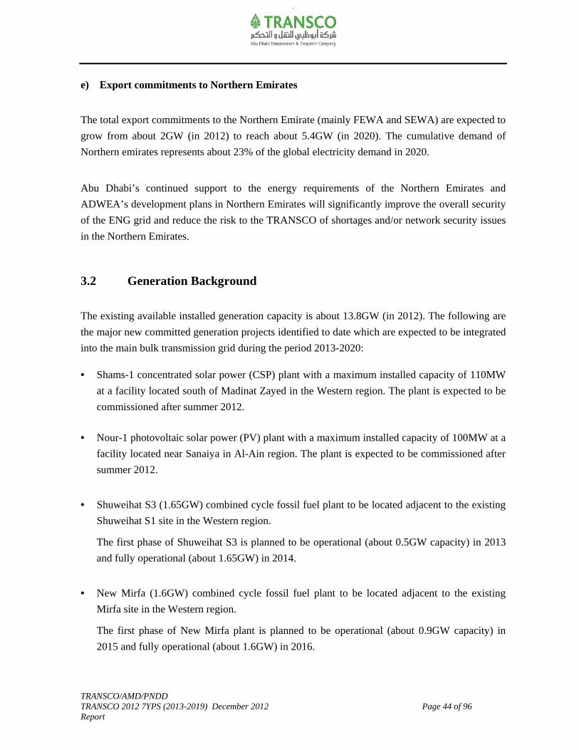
TRANSCO/AMD/PNDD TRANSCO 2012 7YPS (2013-2019) December 2012 Page 44 of 96 Report
e) Export commitments to Northern Emirates
The total export commitments to the Northern Emirate (mainly FEWA and SEWA) are expected to
grow from about 2GW (in 2012) to reach about 5.4GW (in 2020). The cumulative demand of
Northern emirates represents about 23% of the global electricity demand in 2020.
Abu Dhabi’s continued support to the energy requirements of the Northern Emirates and
ADWEA’s development plans in Northern Emirates will significantly improve the overall security
of the ENG grid and reduce the risk to the TRANSCO of shortages and/or network security issues
in the Northern Emirates.
3.2 Generation Background
The existing available installed generation capacity is about 13.8GW (in 2012). The following are
the major new committed generation projects identified to date which are expected to be integrated
into the main bulk transmission grid during the period 2013-2020:
• Shams-1 concentrated solar power (CSP) plant with a maximum installed capacity of 110MW
at a facility located south of Madinat Zayed in the Western region. The plant is expected to be
commissioned after summer 2012.
• Nour-1 photovoltaic solar power (PV) plant with a maximum installed capacity of 100MW at a
facility located near Sanaiya in Al-Ain region. The plant is expected to be commissioned after
summer 2012.
• Shuweihat S3 (1.65GW) combined cycle fossil fuel plant to be located adjacent to the existing
Shuweihat S1 site in the Western region.
The first phase of Shuweihat S3 is planned to be operational (about 0.5GW capacity) in 2013
and fully operational (about 1.65GW) in 2014.
• New Mirfa (1.6GW) combined cycle fossil fuel plant to be located adjacent to the existing
Mirfa site in the Western region.
The first phase of New Mirfa plant is planned to be operational (about 0.9GW capacity) in
2015 and fully operational (about 1.6GW) in 2016.
TRANSCO/AMD/PNDD TRANSCO 2012 7YPS (2013-2019) December 2012 Page 45 of 96 Report
• The Barakah site in the Western region has been identified to promote nuclear generation of
total capacity 5.6GW by 2020. Generator units of 1.4GWe each are expected to be integrated
to the transmission system through 2017-2020.
The total additional generation capacity due to above new committed generation projects
contributes about 8.9GW by 2020.
Some of the existing generation plants are expected to retire in the period 2013-2020. These are
located at Mirfa (141MW) and Madinat Zayed (108MW) in the Western region; Umn Al Nar
(778MW) in the Eastern region and Al-Ain Power Station (256MW) in Al-Ain region. The
available capacity off-set due to the closure of above existing generation will be about 1.3GW by
2020.
Table A1 in Attachment-A includes a detailed summary of generation capacity expansion plan that
shows the existing and committed generation projects in the period 2013-2020.
Figure 3-3 shows the expected demand-supply gap for the ADWEC high, project based and low
demand forecast scenarios. Certain of the demand forecasts indicate a need for additional
generation capacity from 2015 to satisfy the emerging gap between the demand and generation
outlook, and ensure sufficient generation reserve margin is available, particularly to meet the
project based and high demand forecast scenario.
A degree of uncertainty will continue in the realization of the volume, location and timing of new
additional generation capacity in the period 2015-2020. The uncertainty levels in the demand
forecast increases (as evident from the spread between the low and high demand forecast scenario)
particularly from 2015. It should be recognized that the actual commitment to the new
conventional generation capacity takes place on a shorter time scale (about 4 years) to close any
emerging gap between supply and demand. Options are maintained such that the associated
transmission reinforcement works are established in a phased manner to ensure minimum cost and
provide a least regret solution.
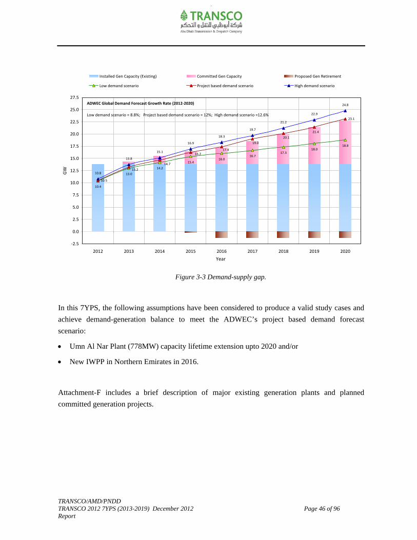
TRANSCO/AMD/PNDD TRANSCO 2012 7YPS (2013-2019) December 2012 Page 46 of 96 Report
Figure 3-3 Demand-supply gap.
In this 7YPS, the following assumptions have been considered to produce a valid study cases and
achieve demand-generation balance to meet the ADWEC’s project based demand forecast
scenario:
Umn Al Nar Plant (778MW) capacity lifetime extension upto 2020 and/or
New IWPP in Northern Emirates in 2016.
Attachment-F includes a brief description of major existing generation plants and planned
committed generation projects.
10.4
13.0
14.2
15.416.0
16.717.3
18.018.8
10.5
23.1
10.8
13.8
15.1
16.9
18.3
19.7
21.2
22.9
24.8
16.2
14.7
13.2
17.4
19.0
20.1
21.4
‐2.5
0.0
2.5
5.0
7.5
10.0
12.5
15.0
17.5
20.0
22.5
25.0
27.5
2012 2013 2014 2015 2016 2017 2018 2019 2020
Year
GW
Installed Gen Capacity (Existing) Committed Gen Capacity Proposed Gen Retirement
Low demand scenario Project based demand scenario High demand scenario
ADWEC Global Demand Forecast Growth Rate (2012‐2020)
Low demand scenario = 8.8%; Project based demand scenario = 12%; High demand scenario =12.6%

TRANSCO/AMD/PNDD TRANSCO 2012 7YPS (2013-2019) December 2012 Page 47 of 96 Report
4.0 Planned Transfers
The requirements for the transmission system development and its associated investments are
primarily driven by the demand and generation backgrounds and the resulting power transfers on
the transmission system. There are uncertainties associated with the demand and generation
backgrounds as with any forecasts and plans. These uncertainties will affect future planned power
transfers on the transmission system and hence the way the transmission system develops. Using
the scenarios developed, the planned power transfers on the transmission system are established
for the most probable demand-generation scenario envisaged in the period 2012-2020 and ensure
consistency with the long-term approach. Envelopes of possible transfers are established and the
most likely (best-view) planned power transfers are identified across each of the transmission
corridors that is used as a basis to inform how best to develop the transmission system.
The most likely (best-view) planned power transfers are based on ADWEC’s project based
demand forecast scenario. An envelope of possible transfers is established for the ADWEC’s low
and high demand forecast scenarios.
The scenario analysis establishes the most likely power transfers across each of the identified
transmission corridors. These corridors are:
From Western region to other regions.
From Northern Emirates to other regions.
From Eastern region to other regions.
To Abu Dhabi islands’ from Eastern region.
To Al-Ain region from other regions.
Figure 4-1 shows the envelope of possible transfers and the best-view planned transfers across the
five identified boundary corridors for the peak demand-generation background during the period
2012-2020.
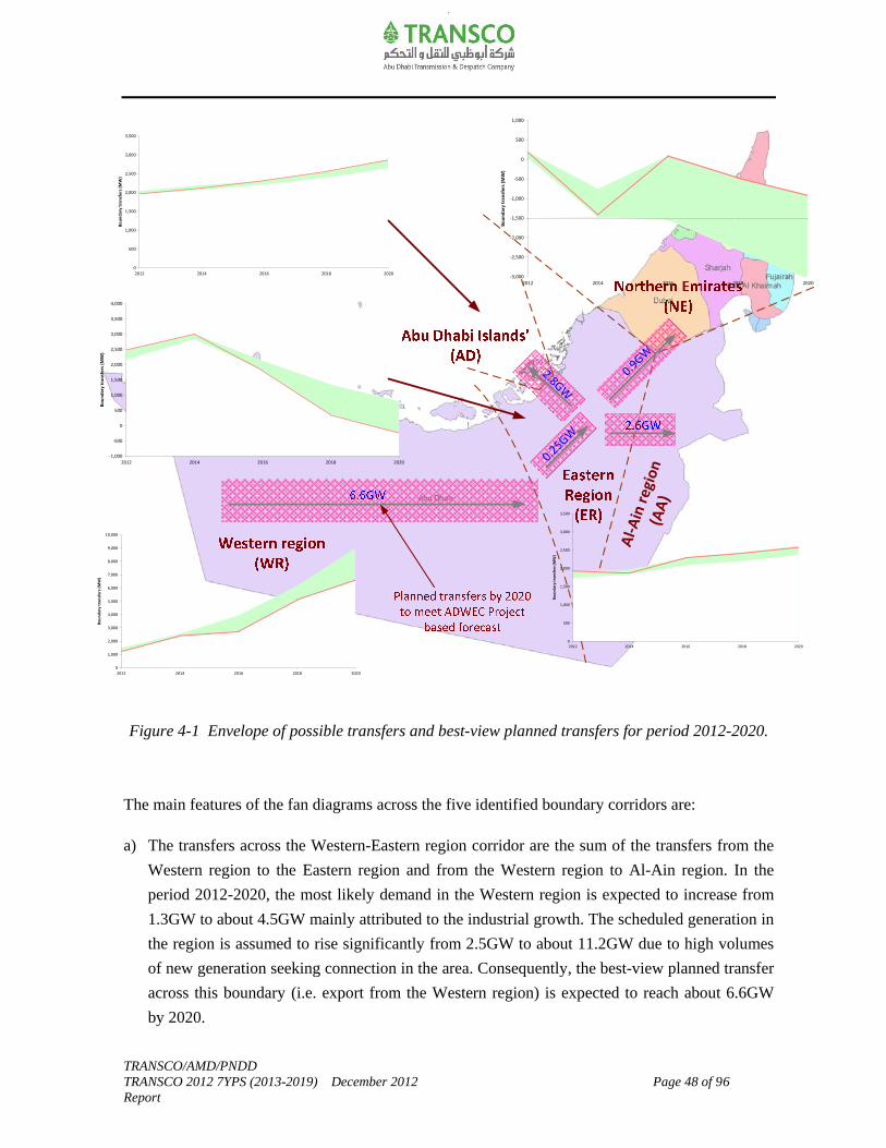
TRANSCO/AMD/PNDD TRANSCO 2012 7YPS (2013-2019) December 2012 Page 48 of 96 Report
Figure 4-1 Envelope of possible transfers and best-view planned transfers for period 2012-2020.
The main features of the fan diagrams across the five identified boundary corridors are:
a) The transfers across the Western-Eastern region corridor are the sum of the transfers from the
Western region to the Eastern region and from the Western region to Al-Ain region. In the
period 2012-2020, the most likely demand in the Western region is expected to increase from
1.3GW to about 4.5GW mainly attributed to the industrial growth. The scheduled generation in
the region is assumed to rise significantly from 2.5GW to about 11.2GW due to high volumes
of new generation seeking connection in the area. Consequently, the best-view planned transfer
across this boundary (i.e. export from the Western region) is expected to reach about 6.6GW
by 2020.
Al-
Ain
reg
ion
(AA
)0
1,000
2,000
3,000
4,000
5,000
6,000
7,000
8,000
9,000
10,000
2012 2014 2016 2018 2020
Bo
un
dar
y tr
an
sfer
s (M
W)
0
500
1,000
1,500
2,000
2,500
3,000
3,500
2012 2014 2016 2018 2020
Bo
un
dar
y tr
ansf
ers
(MW
)
0
500
1,000
1,500
2,000
2,500
3,000
3,500
2012 2014 2016 2018 2020
Bo
un
dar
y tr
ansf
ers
(MW
)
‐1,000
‐500
0
500
1,000
1,500
2,000
2,500
3,000
3,500
4,000
2012 2014 2016 2018 2020
Bo
un
dar
y tr
ansf
ers
(M
W)
0.9GW
2.8GW
0.25GW
‐3,000
‐2,500
‐2,000
‐1,500
‐1,000
‐500
0
500
1,000
2012 2014 2016 2018 2020
Bo
un
dar
y tr
ansf
ers
(MW
)
TRANSCO/AMD/PNDD TRANSCO 2012 7YPS (2013-2019) December 2012 Page 49 of 96 Report
b) The transfers across the Northern Emirates-other regions corridor are the sum of the transfers
from the Northern Emirates to the Eastern region and from the Northern Emirates to Al-Ain
region. In the period 2012-2020, the most likely demand in the Northern Emirates is expected
to increase from 2.2GW to about 5.8GW. The scheduled generation in the region is assumed to
rise from 2.4GW to about 4.9GW. Consequently, the best-view planned transfer across this
boundary (i.e. import to the Northern Emirates) is expected to reach about 0.9GW by 2020.
c) The transfers across the Eastern region-other regions include transfers from the Eastern region
to Abu Dhabi islands’, plus Eastern region to Al-Ain region, minus Western region to Eastern
region, minus Northern Emirates to Eastern region. In the period 2012-2020, the most likely
demand in the Eastern region is expected to increase from 2.9GW to about 6.7GW. The
scheduled generation in the region is assumed to rise from 5.5GW to about 6.6GW. The net
best-view planned transfer to the Eastern region is expected to reach about 0.25GW in 2020.
d) The transfers to the Abu Dhabi islands’ are from the Eastern region. The Abu Dhabi islands’
region constitutes Abu Dhabi island, Reem, Suwa and Sadiyat islands. In the period 2012-
2020, the most likely demand in the Abu Dhabi islands’ is expected to increase from 1.9GW to
about 2.8GW. There is no generation in this region. Hence, the best-view planned transfer
across this boundary is expected to meet the demands in the region.
e) The transfers to the Al-Ain region are from other regions namely from the Eastern, Western
regions and Northern Emirates. In the period 2012-2020, the most likely demand in the Al-Ain
region is expected to increase from 1.9GW to about 2.8GW. The scheduled generation (from
renewables) in the region is expected to contribute about 0.2GW by 2020. Consequently, the
best-view planned transfer across this boundary is expected to be about 2.6GW in 2020.
TRANSCO/AMD/PNDD TRANSCO 2012 7YPS (2013-2019) December 2012 Page 50 of 96 Report
5.0 Evolution of Transmission Network
The Electricity Transmission System Security Standard, Issue 1, Rev (0) dated March 2005 sets
out the criteria and methodology, which TRANSCO shall use in the planning, development,
operation and maintenance of the electricity transmission system. The Electricity Transmission
Code (Ver.1, Rev.4, issued in January 2012) contains additional criteria and other aspects of
quality of supply standards that shall be considered for planning the transmission network. For
details refer to the above-mentioned standard and code available in our website www.transco.ae.
The Electricity Transmission System Security Standard is expected to undergo a review. The terms
of references for the review were agreed with all the stakeholders and the project is expected to
kick off in 2013.
This chapter presents the evolution of the 400kV, 220kV and 132kV transmission system within
the Emirate of Abu Dhabi and, where appropriate, TRANSCO network outside of the authorized
area up to 2020.
It should be noted that some of the transmission schemes included in this 7YPS are still in the
early planning stage and options are kept open due to significant uncertainty in the demand-
generation backgrounds particularly from 2015 and beyond. Hence, a significant amount of work
is still required to be performed for those schemes. The requirements will be kept under review
taking into account any updates on the demand-generation background and network developments
before committing capital expenditure on those works. All options are maintained for possible
optimization and based on the chosen scheme option and updated requirements, the timing of the
related reinforcement works may be altered to ensure no regret solution.
Figure 5-1 shows the existing main bulk 400kV transmission network (as in 2012) spread across
the five regions (Western region, Eastern region, Abu Dhabi Islands’, Al-Ain region and Northern
Emirates).
Attachment-B includes detailed topology diagrams of the electrical power transmission system for
the period 2012-2020. It should be noted that the reference date for inclusion of any new asset
shown in the transmission network topology is the summer peak of the respective year. However,
if any asset is expected to be commissioned after the summer peak of that year, the same is shown
in the transmission network topology of the following year.
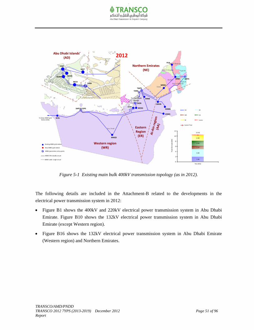
TRANSCO/AMD/PNDD TRANSCO 2012 7YPS (2013-2019) December 2012 Page 51 of 96 Report
Figure 5-1 Existing main bulk 400kV transmission topology (as in 2012).
The following details are included in the Attachment-B related to the developments in the
electrical power transmission system in 2012:
Figure B1 shows the 400kV and 220kV electrical power transmission system in Abu Dhabi
Emirate. Figure B10 shows the 132kV electrical power transmission system in Abu Dhabi
Emirate (except Western region).
Figure B16 shows the 132kV electrical power transmission system in Abu Dhabi Emirate
(Western region) and Northern Emirates.
2010 Best View (30GW)
ASWG
DHMG
SWHN
MOSG
SHME
WRSN
DHID
FILA
WMZD
SHPS & S2PS
QDFA
SASNBECH
QURM
ADST
REEM
SDYT
TWPS
Existing 400kV grid station
New 400kV grid station
400kV OHL double circuit
400kV cable single circuit
400kV generation entry points
To Abu Dhabi Islands’
ICAD
To Salwa 400kV grid Station (KSA)
GCSL
Abu Dhabi Islands’(AD)
Northern Emirates(NE)
Al-
Ain
reg
ion
(AA
)
Western region (WR)
TANE
SASN
Eastern Region
(ER)
2012
1.96
3.00
1.27
1.93
2.20
10.46
0
2
4
6
8
10
12
Year 2012
Pe
ak
De
man
d (G
W)
AD ER
WR AA
NE Losses
System Total
TRANSCO/AMD/PNDD TRANSCO 2012 7YPS (2013-2019) December 2012 Page 52 of 96 Report
2013-2014
Major committed 400kV transmission system expansion projects are expected to be completed
during the period 2013-2014 to meet the system needs and to accommodate committed new
generation projects.
The 400kV transmission facilities from the existing Shuweihat Power Station (SHPS/S2PS) is
capable of evacuating power from both Shuweihat S1 & S2 generation (total about 3.2GW) to
meet the system demand requirements. To evacuate power from the Shuweihat S3 generation
(about 1.65GW), a new 400kV grid station (S3PS) and related 400kV overhead line transmission
facilities are planned to be completed in 2013.
New 400kV grid stations and related 400kV overhead line works are expected to be integrated to
the transmission network in the period 2013-2014 to meet the respective regions’ demand
requirements. These are 400/220kV grid stations in Ruwais (RWSG) and BAAB (in Western
region); 400/132kV grid stations in Bahia (BHYG), Mahawi (MHWG) and Shamkha (SMKG) (in
Eastern region); and 400/132kV grid stations in Ajman (AJMN) and New Fujairah City (FJCT) in
Northern Emirates.
Restrictions are placed by Government and developers for building new 400kV overhead lines
and/or replacing existing overhead lines within Abu Dhabi island, along Abu Dhabi island-
Sadiyat-Bahia (ADST-SDYT-BHYG) and Sas Al Nakheel-Mahawi-Mussafah (SASN-MHWG-
MOSG) corridors in the Eastern region. Hence, TRANSCO has been required to increasingly
underground transmission infrastructure serving these areas. The 400kV underground cables’
projects along the ADST-SDYT-BHYG corridor and SASN-MHWG-MOSG corridors have been
staged through 2013-2016. This is to ensure that the performance of 400kV XLPE cables will be
demonstrated satisfactorily and thereby enable the policy decision to dismantle the 400kV
overhead lines along the said corridors thereafter.
Figure 5-2 shows the main bulk 400kV transmission network topology in 2014.
The 220kV modification works at Madinat Zayed (in Western region) has been completed and
commissioned to facilitate integration of Masdar CSP Shams-1 Solar Plant (an updated status since
the release of the draft version). The 220kV works at Sanaiya (in Al-Ain region) is expected to be
completed before summer 2013 to facilitate integration of Noor-1 PV Solar Plant. There are
number of 220kV and 132kV works currently being executed either to meet customer requirements

TRANSCO/AMD/PNDD TRANSCO 2012 7YPS (2013-2019) December 2012 Page 53 of 96 Report
or comply with network security and are expected to be completed in the period 2013-2014.
A brief description of these works and their high-level need/drivers for initiating the projects
among other information are detailed in Table 9-1, Chapter-9.
The following details are included in the Attachment-B related to the developments in the
electrical power transmission system in the period 2013-2014:
Figure B2 shows the 400kV and 220kV electrical power transmission system in Abu Dhabi
Emirate for 2013. Figure B11 shows the 132kV electrical power transmission system in
Abu Dhabi Emirate (except Western region) in 2013.
Figure B17 shows the 132kV electrical power transmission system in Abu Dhabi Emirate
(Western region) and Northern Emirates in 2013.
Figure B3 shows the 400kV and 220kV electrical power transmission system in Abu Dhabi
Emirate for 2014. Figure B12 shows the 132kV electrical power transmission system in
Abu Dhabi Emirate (except Western region) in 2014.
Figure B18 shows the 132kV electrical power transmission system in Abu Dhabi Emirate
(Western region) and Northern Emirates in 2014.
Figure 5-2 Main bulk 400kV transmission network topology in 2014.
2010 Best View (30GW)
ASWG
DHMG
SWHN
MOSG
SHME
WRSN
DHID
FILA
WMZD
SHPS & S2PS
QDFA
SASNBECH
QURM
ADST
REEM
SDYT
TWPS
Existing 400kV grid station
New 400kV grid station
Existing 400kV double circuit-standard rating
New 400kV double circuit-standard rating
Existing 400kV Cable Single Circuit New 400kV Cable Single Circuit
Single 400kV OHL Circuit
400kV generation entry points
ICAD
To Salwa 400kV grid Station (KSA)
GCSL
Abu Dhabi Islands’(AD)
Northern Emirates(NE)
Al-
Ain
reg
ion
(AA
)
Western region (WR)
TANE
SASN
Eastern Region
(ER)
BHYG
MHWG
BHYG
SMKG
AJMN
S3PS
RWSGBAAB
New 400kV double circuit-higher rating-2000MVA/circuit
2014
2.11
3.75
2.36
2.11
4.19
14.67
0
2
4
6
8
10
12
14
16
Year 2014
Pe
ak
De
man
d (G
W)
AD ER
WR AA
NE Losses
System Total
FJCT
TRANSCO/AMD/PNDD TRANSCO 2012 7YPS (2013-2019) December 2012 Page 54 of 96 Report
2015-2016
A new 400kV grid station (MRPS) and related 400kV overhead line transmission facilities are
planned in 2015 to evacuate power from the new Mirfa generation plant (1.6GW). The 400kV
transmission scheme for integrating new Mirfa generation is currently under study and options are
maintained for possible optimization subject to detailed feasibility study. Based on the scheme
option chosen the timing of the related reinforcement works may be altered (e.g. advancing 400kV
overhead line reinforcement work between the Ruwais-Hameem/Faya corridor).
A new 400kV grid station (Braka switchyard-1) and related 400kV overhead line transmission
facilities are planned in 2015 to facilitate the start-up operations of Braka nuclear power plant and
enable the phased integration of the nuclear power generation at Braka. The 400kV West-East
corridor reinforcements ensure an integrated approach for evacuating power from Shuweihat S3,
Mirfa and Braka power plants while meeting the demands in the Western region.
The 400kV overhead line reconfiguration works between BHYG and TANE/TWPS are staged
through 2015-2016 to enable dismantling the existing 400kV overhead line circuits along ADST-
SDYT-BHYG corridor.
A third 400/132kV 500MVA transformer at Sas Al Nakheel 400/132kV grid station (in Eastern
region) is planned during this period to meet the demand growth in the region and to off-set the
capacity shortfall in SASN Zone after the retirement of UAN generation in end 2015.
Figure 5-3 shows the main bulk 400kV transmission network topology in 2016.
There are number of 220kV and 132kV works currently in the planning stage either to meet the
customer requirements or comply with network security, whilst few of these works are currently in
tendering/execution stage. All these works are expected to be completed in the period 2015-2016.
A brief description of these works and their high-level need/drivers for initiating the projects
among other information are detailed in Table 9-1, Chapter-9.
The following details are included in the Attachment-B related to the developments in the
electrical power transmission system in the period 2015-2016:
Figure B4 shows the 400kV and 220kV electrical power transmission system in Abu Dhabi
Emirate for 2015. Figure B13 shows the 132kV electrical power transmission system in
Abu Dhabi Emirate (except Western region) in 2015.
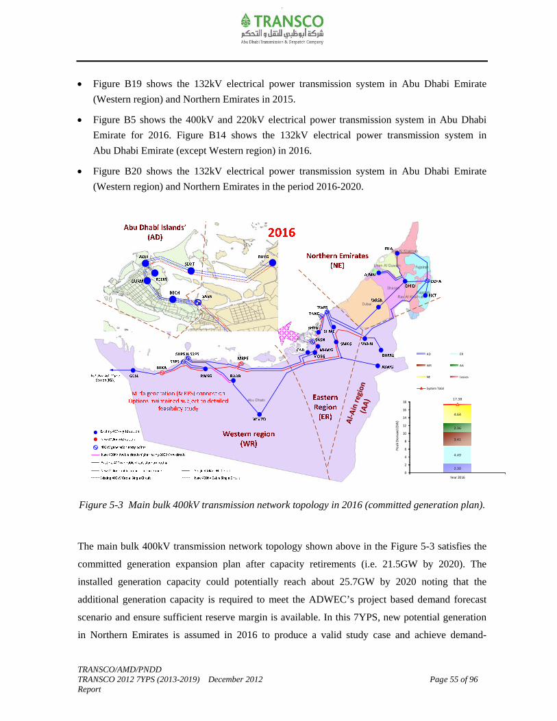
TRANSCO/AMD/PNDD TRANSCO 2012 7YPS (2013-2019) December 2012 Page 55 of 96 Report
Figure B19 shows the 132kV electrical power transmission system in Abu Dhabi Emirate
(Western region) and Northern Emirates in 2015.
Figure B5 shows the 400kV and 220kV electrical power transmission system in Abu Dhabi
Emirate for 2016. Figure B14 shows the 132kV electrical power transmission system in
Abu Dhabi Emirate (except Western region) in 2016.
Figure B20 shows the 132kV electrical power transmission system in Abu Dhabi Emirate
(Western region) and Northern Emirates in the period 2016-2020.
Figure 5-3 Main bulk 400kV transmission network topology in 2016 (committed generation plan).
The main bulk 400kV transmission network topology shown above in the Figure 5-3 satisfies the
committed generation expansion plan after capacity retirements (i.e. 21.5GW by 2020). The
installed generation capacity could potentially reach about 25.7GW by 2020 noting that the
additional generation capacity is required to meet the ADWEC’s project based demand forecast
scenario and ensure sufficient reserve margin is available. In this 7YPS, new potential generation
in Northern Emirates is assumed in 2016 to produce a valid study case and achieve demand-
Al-
Ain
reg
ion
(AA
)
2.30
4.49
3.41
2.36
4.64
17.38
0
2
4
6
8
10
12
14
16
18
Year 2016
Pe
ak
De
man
d (G
W)
AD ER
WR AA
NE Losses
System Total
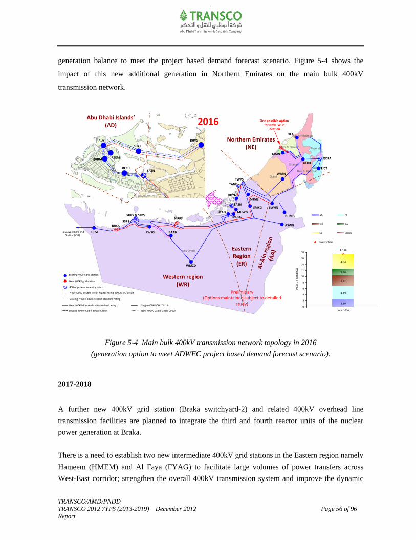
TRANSCO/AMD/PNDD TRANSCO 2012 7YPS (2013-2019) December 2012 Page 56 of 96 Report
generation balance to meet the project based demand forecast scenario. Figure 5-4 shows the
impact of this new additional generation in Northern Emirates on the main bulk 400kV
transmission network.
Figure 5-4 Main bulk 400kV transmission network topology in 2016
(generation option to meet ADWEC project based demand forecast scenario).
2017-2018
A further new 400kV grid station (Braka switchyard-2) and related 400kV overhead line
transmission facilities are planned to integrate the third and fourth reactor units of the nuclear
power generation at Braka.
There is a need to establish two new intermediate 400kV grid stations in the Eastern region namely
Hameem (HMEM) and Al Faya (FYAG) to facilitate large volumes of power transfers across
West-East corridor; strengthen the overall 400kV transmission system and improve the dynamic
2010 Best View (30GW)
ASWG
DHMG
SWHN
MOSG
SHME
WRSN
DHID
FILA
WMZD
SHPS & S2PS
QDFA
SASNBECH
QURM
ADST
REEM
SDYT
TWPS
ICAD
To Salwa 400kV grid Station (KSA)
GCSL
Abu Dhabi Islands’(AD)
Northern Emirates(NE)
Al-
Ain
reg
ion
(AA
)Western region
(WR)
TANE
SASN
Eastern Region
(ER)
BHYG
MHWG
BHYG
SMKG
AJMN
S3PS
RWSG BAAB
BRKA
MRPS
Existing 400kV grid station
New 400kV grid station
Existing 400kV double circuit-standard rating
New 400kV double circuit-standard rating
Existing 400kV Cable Single Circuit New 400kV Cable Single Circuit
Single 400kV OHL Circuit
400kV generation entry points
New 400kV double circuit-higher rating-2000MVA/circuit
2016
2.30
4.49
3.41
2.36
4.64
17.38
0
2
4
6
8
10
12
14
16
18
Year 2016
Pe
ak
De
man
d (G
W)
AD ER
WR AA
NE Losses
System Total
One possible option for New IWPP
location
FJCT
Preliminary(Options maintained subject to detailed
study)

TRANSCO/AMD/PNDD TRANSCO 2012 7YPS (2013-2019) December 2012 Page 57 of 96 Report
performance of the transmission network. This is achieved through major 400kV overhead line
reinforcement works between Braka (BRKA)-Madinat Zayed (WMZD) grid stations in the
Western region; Ruwais (RWSG)-Al Faya (FYAG) grid stations in the West-East corridor;
Hameem (HMEM)-ICAD grid stations in the Eastern region.
A fourth 400/132kV 500MVA transformer at Mahawi 400/132kV grid station (in Eastern region)
is planned during this period to meet the demand growth in the region.
The 400kV overhead line reconfiguration works between TANE and TWPS are planned to be
completed during this period thereby removing the current generation constraint at TANE 400kV
grid station.
Figure 5-5 shows the main 400kV transmission network topology in 2018.
Figure 5-5 Main bulk 400kV transmission network topology in 2018.
2.55
5.56
3.98
2.58
5.16
20.15
0
2
4
6
8
10
12
14
16
18
20
22
Year 2018
Pe
ak
De
man
d (G
W)
AD ER
WR AA
NE Losses
System Total
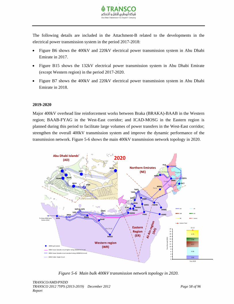
TRANSCO/AMD/PNDD TRANSCO 2012 7YPS (2013-2019) December 2012 Page 58 of 96 Report
The following details are included in the Attachment-B related to the developments in the
electrical power transmission system in the period 2017-2018:
Figure B6 shows the 400kV and 220kV electrical power transmission system in Abu Dhabi
Emirate in 2017.
Figure B15 shows the 132kV electrical power transmission system in Abu Dhabi Emirate
(except Western region) in the period 2017-2020.
Figure B7 shows the 400kV and 220kV electrical power transmission system in Abu Dhabi
Emirate in 2018.
2019-2020
Major 400kV overhead line reinforcement works between Braka (BRAKA)-BAAB in the Western
region; BAAB-FYAG in the West-East corridor; and ICAD-MOSG in the Eastern region is
planned during this period to facilitate large volumes of power transfers in the West-East corridor;
strengthen the overall 400kV transmission system and improve the dynamic performance of the
transmission network. Figure 5-6 shows the main 400kV transmission network topology in 2020.
Figure 5-6 Main bulk 400kV transmission network topology in 2020.
2010 Best View (30GW)
ASWG
DHMG
SWHN
MOSG
SHME
WRSN
DHID
FILA
WMZD
SHPS & S2PS
QDFA
SASNBECH
QURM
ADST
REEM
SDYT
TWPS
ICAD
To Salwa 400kV grid Station (KSA)
GCSL
Abu Dhabi Islands’(AD)
Northern Emirates(NE)
Al-
Ain
reg
ion
(AA
)
Western region (WR)
TANE
SASN
Eastern Region
(ER)
BHYG
MHWG
BHYG
SMKG
AJMN
S3PS
RWSGBAAB
BRKA
MRPS
FYAGHMEM
2020
2.85
6.68
4.57
2.88
5.75
23.12
0
2
4
6
8
10
12
14
16
18
20
22
24
Year 2020
Pe
ak
De
man
d (G
W)
AD ER
WR AA
NE Losses
System Total
FJCT
400kV tower (double circuit-standard rating-1400MVA/circuit)
400kV Cable Single Circuit
400kV grid station
400kV tower (double circuit-higher rating-2000MVA/circuit)
TRANSCO/AMD/PNDD TRANSCO 2012 7YPS (2013-2019) December 2012 Page 59 of 96 Report
The following details are included in the Attachment-B related to the developments in the
electrical power transmission system in the period 2019-2020:
Figure B8 shows the 400kV and 220kV electrical power transmission system in Abu Dhabi
Emirate in 2019.
Figure B9 shows the 400kV and 220kV electrical power transmission system in Abu Dhabi
Emirate in 2020.
TRANSCO has historically used 400kV double circuit overhead lines rated at 1400MVA per
circuit based on a quad bundle Dove conductor arrangement, as standard. Based on the power
system planning studies, there is a need to increase the 400kV overhead line circuit ratings to
2000MVA for certain circuits taking into account the developments in the grid. The quad cardinal
bundle arrangement (ACSR/AS) provides the most attractive solution and planned to be adopted
on relevant 400kV overhead line circuits (RWSG-BAAB; RWSG-FYAG; BAAB-FYAG) in the
West-East transmission corridor and ICAD-MOSG corridor.
Consideration has also been given to the impact of any potential exports to systems outside of its
authorized area (about 2GW in addition to the current committed exports) on the Abu Dhabi
transmission network topology in 2020. Also, there is a need to establish new 400kV grid supply
nodes in Abu Dhabi island and Al-Ain region in the period 2019-2020 to alleviate the expected
capacity shortfall in the regions’ in order to meet the ADWEC’s project based demand forecast
scenario. These will not only enable additional transmission corridor across Abu Dhabi island and
Al-Ain region, but also meets the system requirements in 2020 and beyond. Figure 5-7 shows the
proposed changes in the main bulk 400kV network topology in 2020 taking into account the above
possible developments. These proposals are still preliminary at this stage and options are
maintained which will be subject to detailed studies on confirmation of firm requirements.
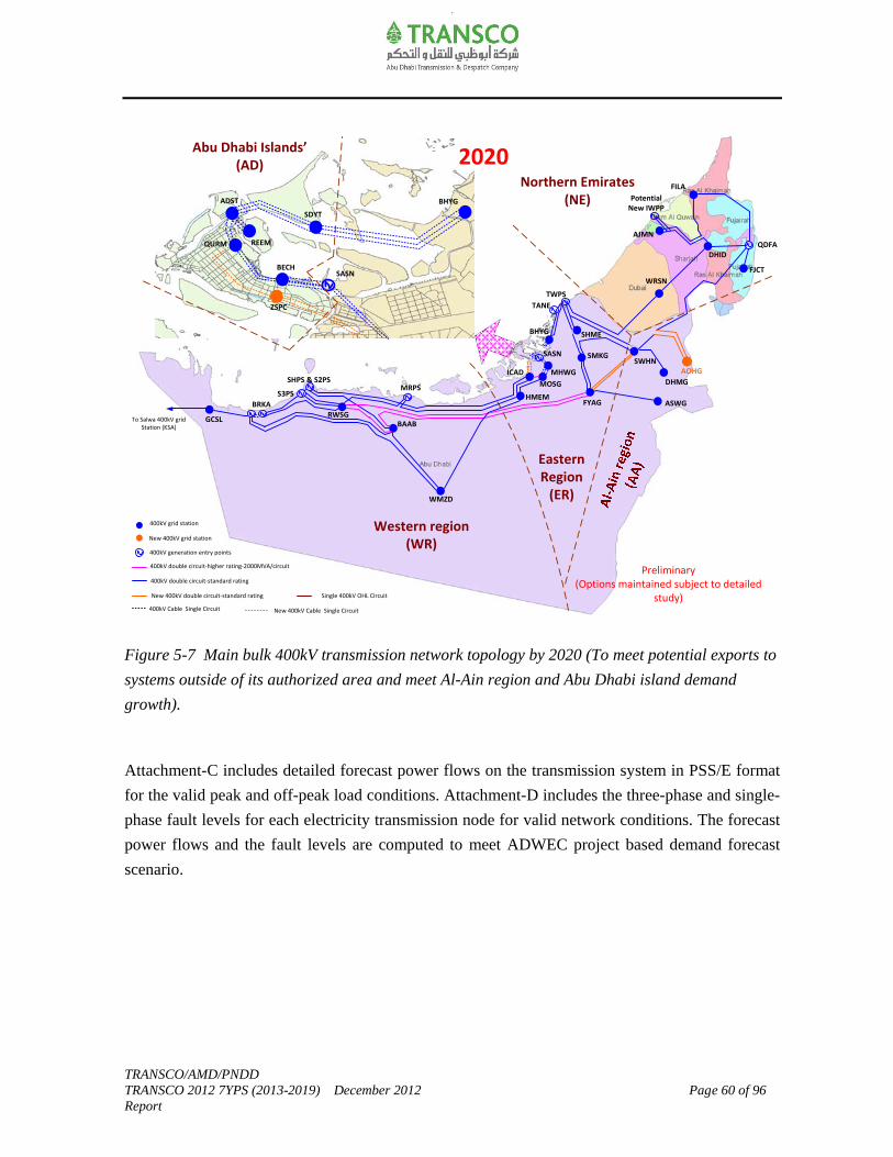
TRANSCO/AMD/PNDD TRANSCO 2012 7YPS (2013-2019) December 2012 Page 60 of 96 Report
Figure 5-7 Main bulk 400kV transmission network topology by 2020 (To meet potential exports to
systems outside of its authorized area and meet Al-Ain region and Abu Dhabi island demand
growth).
Attachment-C includes detailed forecast power flows on the transmission system in PSS/E format
for the valid peak and off-peak load conditions. Attachment-D includes the three-phase and single-
phase fault levels for each electricity transmission node for valid network conditions. The forecast
power flows and the fault levels are computed to meet ADWEC project based demand forecast
scenario.
2010 Best View (30GW)
ASWG
DHMG
SWHN
MOSG
SHME
WRSN
DHID
FILA
WMZD
SHPS & S2PS
QDFA
SASNBECH
QURM
ADST
REEM
SDYT
TWPS
ICAD
To Salwa 400kV grid Station (KSA)
GCSL
Abu Dhabi Islands’(AD)
Northern Emirates(NE)
Western region (WR)
TANE
SASN
Eastern Region
(ER)
BHYG
MHWG
BHYG
SMKG
AJMN
S3PS
RWSGBAAB
BRKA
MRPS
FYAGHMEM
400kV grid station
New 400kV grid station
400kV double circuit-standard rating
New 400kV double circuit-standard rating
400kV Cable Single Circuit
400kV generation entry points
400kV double circuit-higher rating-2000MVA/circuit
Single 400kV OHL Circuit
2020
AOHG
Preliminary(Options maintained subject to detailed
study)
FJCT
ZSPC
New 400kV Cable Single Circuit
Potential New IWPP

TRANSCO/AMD/PNDD TRANSCO 2012 7YPS (2013-2019) December 2012 Page 61 of 96 Report
6.0 Asset Replacement Works
In addition to enhancing network capacity there is a need to replace certain assets. The requirement to replace aging assets affecting network security include:
Transformers (132/11kV transformers at EMBS/SLTC substation; and 220/33kV
transformer at Al-Ain Power Station).
Protection (busbar, line and transformer protection upgrade at various sites).
Batteries and chargers at various sites (e.g. DHMG-220, AAPS-220, AHYG-220 etc).
LV switchgear replacement at Jabel Hafeet 33kV substation.
Underground cables (replacement of oil filled to XLPE between ADST-FDRS)
Overhead lines (220kV Ruwais-Sila OPGW rehabilitation works).
SVC cooling and control system upgrade at AAPS, ASWG and MOSG.
Others (SCMS, FMS upgrade).
The requirement to replace/decommission aging assets affecting network security and exploit the
synergies with capacity related asset creation include:
220/33kV grid stations at Mirfa, Zakher, AAPS and Al Wagon.
132kV cable circuit between Mushrif-Mussafah/Mussafah-Umn Al Nar.
The economic treatment of the assets that are expected to be decommissioned will be treated in
accordance with TRANSCO’s asset policy and shall be written off from the regulatory asset base
when disposed of after due approval from RSB.
Further details on the asset replacement works for the period 2013-2020 is summarized in
Table 10-1, Chapter-10.

TRANSCO/AMD/PNDD TRANSCO 2012 7YPS (2013-2019) December 2012 Page 62 of 96 Report
7.0 Network Operation and Despatch
The committed new generation expansion projects, the retirement plans of some existing
generation plants, and the potential new capacity additions to meet the “ADWEC’s project based
forecast” is fully described in Chapter-3, Section 3.2 of 7YPS.
The Abu Dhabi power transmission system has been connected to systems outside of its authorized
area to the Northern Emirates through the regional grid interconnection (Emirates National Grid -
ENG). In the period to 2020 ADWEA’s transmission development plans in Northern Emirates will
continue to grow considerably in order to support the increasing energy requirements of the
neighboring Emirates. International grid interconnections through the Gulf Cooperation Council
Interconnection Authority (GCCIA) network have been established.
In this Chapter, the changes to the generation portfolio and its impact on the despatch; and the
potential changes to the transmission system operational requirements will be described.
7.1 Generation Despatch
The existing available installed generation capacity is about 13.8GW (in 2012). Figure 7-1 shows
the existing electricity generation portfolio.
Figure 7-1 Existing electricity generation portfolio (in 2012).
94%
6%
Simple/Open cycle Combined cycle/Cogen

TRANSCO/AMD/PNDD TRANSCO 2012 7YPS (2013-2019) December 2012 Page 63 of 96 Report
The available net installed generation capacity is to forecast to reach about 21.5GW by 2020
taking into account the committed generation expansion plan and generation capacity retirement
plan (data as on April 2012). The installed generation capacity could potentially reach about
25.7GW by 2020 noting that the additional generation capacity is required to meet the ADWEC’s
project based demand forecast scenario.
Figure 7-2 shows the expected electricity generation mix in 2020 to achieve 21.5GW (committed
plan) and 25.7GW (plan to meet ADWEC’s project based demand forecast scenario). The
contribution of nuclear and other renewables (solar/wind) generation mix is expected to reach
about 27%-28% of the total generation portfolio.
Figure 7-2 Forecast electricity generation portfolio (in 2020).
Electricity Generation Portfolio in 2020
(Only Committed projects as on April 2012 included)
1%
26%
63%
10%
Simple/Open cycle Combined cycle/Cogen
Nuclear Other Renewables (Solar/Wind)
Electricity Generation Portfolio in 2020
(To meet ADWEC Project based forecast)
6% 8%
64%
22%
Simple/Open cycle Combined cycle/Cogen
Nuclear Other Renewables (Solar/Wind)

TRANSCO/AMD/PNDD TRANSCO 2012 7YPS (2013-2019) December 2012 Page 64 of 96 Report
The power and water demand is met by despatching production facilities in accordance with a Unit
Commitment model. Given the power and water system characteristics, together with the changing
characteristics particularly associated with production facilities used to meet this demand, there is
a need to ensure both power and water requirements will be securely met in an efficient manner.
Figure 7-3 shows the current generation mix making up the annual load duration curve. For the
2012, the average winter/summer demand ratio is assumed 32% and the average load factor of the
system demand about 65%.
Figure 7-3 Generation mix making up the annual load duration curve (in 2012).
The generation mix along with the expected increase in the industrial demand and export
requirements will alter the average winter/summer demand ratio to about 35% and the average
load factor of the system demand about 70%. The impact of these changes and the need to take
into account the inter-relationship between power and water production, will require a combination
of some or all of the following:
Introducing a degree of flexibility into the despatch of certain power plant units including the
nuclear plant.
Managing maintenance and refueling of the nuclear plant to times of minimum demand.
0
10
20
30
40
50
60
70
80
90
100
0% 5% 9% 14% 18% 23% 27% 32% 37% 41% 46% 50% 55% 59% 64% 69% 73% 78% 82% 87% 91% 96%
Year Time (%)
De
man
d (
%)
3.4GW
10.5GW
Flexible combined cycle/cogen
Simple/open cycle (~0.8GW i.e. 7.5%)
Must run combined cycle/cogen to meet
water requirements (~3.4GW i.e. 32%)
TRANSCO/AMD/PNDD TRANSCO 2012 7YPS (2013-2019) December 2012 Page 65 of 96 Report
Introducing alternative approaches to water production and storage particularly during the off-
peak season.
Exports to customers outside the authorized area.
This is now subject of a detailed economic despatch study that will report in 2013. 7.2 Network Operation
In the period to 2020 the peak demand on the transmission network will increase from about
10.5GW (in 2012) to between 18.8GW-24.8GW in 2020. As indicated in the previous section, this
is accompanied by a corresponding increase in the generation. The main changes to the
transmission network operation that TRANSCO will experience as a result of this include:
Fault level management:
Fault levels on the network are increasing dramatically. TRANSCO has taken necessary
operational measures to manage high fault levels at certain nodes in the transmission system; and
where ever appropriate development projects have already been initiated and/or planned to ensure
fault levels are managed within reasonable limits.
Increased use of cables:
Restrictions are placed by Government and developers for building new overhead lines and/or
replacing existing overhead lines within Abu Dhabi island, along Abu Dhabi island-Reem-Sadiyat-
Bahia and Sas Al Nakheel-Mahawi-Mussafah corridors in the Eastern region, and in Al-Ain
region. In view of the above, TRANSCO has been required to increasingly underground
transmission infrastructure serving these areas.
Figure 7-4 shows the 400kV cable developments projects expected to be commissioned in the
vicinity of Abu Dhabi island and Eastern region in the period to 2020.
TRANSCO/AMD/PNDD TRANSCO 2012 7YPS (2013-2019) December 2012 Page 66 of 96 Report
Figure 7-4 400kV cable development projects in the period to 2020.
Figure 7-5 shows the expected increase in the 400kV and 220kV cable circuit lengths in the
Abu Dhabi Emirate in the period to 2020.
Figure 7-5 Expected increase in 400kV and 220kV cable circuit lengths in Abu Dhabi Emirate in
the period to 2020.
Running Project-N6524(Works staged for completion 2014-2016)
Running Project -N7055(Works staged for completion 2014-2016)
Planned Project: N-P-13-022(Planned for completion 2016)
Running Project -N5419(Planned completion 2013)
Planned Project:(Planned for completion 2018)
Planned 400kV cable circuits
Existing 400kV cable circuits
Existing 400kV OHL circuits
(Planned 400/132kV grid station in 2014)
(Planned 400/132kV grid station in 2014)
400kV Grid Station
3x13km
2x23km
3x23km
3x11km
4x3.7km
3x8.5km
2x4.1km
3x2.7km
243.6
142.4
81.30
56.10
0
50
100
150
200
250
300
400kV XLPE Cables 220kV XLPE Cables
Cab
le C
ircu
it L
en
gth (
km)
2012 2020
TRANSCO/AMD/PNDD TRANSCO 2012 7YPS (2013-2019) December 2012 Page 67 of 96 Report
The safe operation of the 400kV cable network is highly related to the operation of the 400kV
shunt reactors. In view of the extensive use of 400kV cables and shunt reactors, TRANSCO has
completed the required studies to optimize the allocation of 400kV shunt reactors in order to
minimize the operational restriction and gain better understanding of the controlled switching
requirements for the 400kV circuit breakers.
Reactive power management:
The location of generation relative to demand is also changing such that the inherent capability of
generation to provide both static and dynamic reactive support is not necessarily located optimally
particularly to aid post fault voltage recovery associated with air conditioning type demands that
are widespread over the country and industrial demand. Static and dynamic compensation will
therefore be required and need to be managed to ensure consumers are provided with an
appropriate quality of supply. Initial analysis has been undertaken to consider reactive
compensation requirements and these will be fully developed in 2013.
TRANSCO/AMD/PNDD TRANSCO 2012 7YPS (2013-2019) December 2012 Page 68 of 96 Report
8.0 Transmission System Capabilities and Constraints
The network development plans and schemes discussed in the previous sections of the report
satisfies the likely best-view power transfers to meet the ADWEC’s project based demand forecast
scenario in different regions across the transmission system. An assessment of the bulk
transmission system capabilities gives an indication the extent to which the system can
accommodate the circumstances outside the chosen likely best view planned transfers. It also
provides an appreciation of opportunities available in the transmission system to accommodate
new generation and demand in different regions across the system.
The transfer capability across the boundary provides a broad appreciation of the overall capability
of the bulk transmission network to transport power. The transfer capability across a particular
boundary is the power flow across that boundary without causing any unacceptable conditions as a
result of Secured Event. Two types of system limitation relating to the transfer of power across a
boundary have been considered. The first relates to thermal limitation and the second voltage
limitation. The overall transfer capability across the boundary is the lower of the thermal (MW)
and voltage limitations. The transfer capability gives an indication of the maximum transfer across
the identified boundary that can be supported without contravening any of the unacceptable
conditions following a “Secured Event”.
Figures 8-1 to Figures 8-5 shows the transfer capabilities, envelope of likely transfers range and
the best-view planned transfers across the five identified boundary corridors. These capabilities are
assumed for specific generation pattern (assuming new IWPP in Northern Emirates as the next
potential generation site option after Mirfa generation).
Western region
Figure 8-1 shows the planned transfers and transfer capability across West-East corridor. The
Western region is considered to be the source, and other regions act as sink. In the period to 2020
major 400kV transmission reinforcements are required to cater for the committed generation and
demand connections in the Western region. The introduction of nuclear generation in the period
2017-2020 mandates major 400kV transmission reinforcements across the West-East corridor
thereby increasing the planned transfers and capabilities across the corridor.
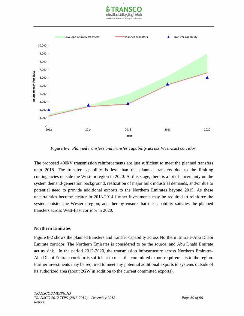
TRANSCO/AMD/PNDD TRANSCO 2012 7YPS (2013-2019) December 2012 Page 69 of 96 Report
Figure 8-1 Planned transfers and transfer capability across West-East corridor.
The proposed 400kV transmission reinforcements are just sufficient to meet the planned transfers
upto 2018. The transfer capability is less than the planned transfers due to the limiting
contingencies outside the Western region in 2020. At this stage, there is a lot of uncertainty on the
system demand-generation background, realization of major bulk industrial demands, and/or due to
potential need to provide additional exports to the Northern Emirates beyond 2015. As these
uncertainties become clearer in 2013-2014 further investments may be required to reinforce the
system outside the Western region; and thereby ensure that the capability satisfies the planned
transfers across West-East corridor in 2020.
Northern Emirates
Figure 8-2 shows the planned transfers and transfer capability across Northern Emirate-Abu Dhabi
Emirate corridor. The Northern Emirates is considered to be the source, and Abu Dhabi Emirate
act as sink. In the period 2012-2020, the transmission infrastructure across Northern Emirates-
Abu Dhabi Emirate corridor is sufficient to meet the committed export requirements to the region.
Further investments may be required to meet any potential additional exports to systems outside of
its authorized area (about 2GW in addition to the current committed exports).
0
1,000
2,000
3,000
4,000
5,000
6,000
7,000
8,000
9,000
10,000
2012 2014 2016 2018 2020
Year
Bo
un
dar
y tr
ansf
ers
(MW
)Envelope of likely transfers Planned transfers Transfer capability

TRANSCO/AMD/PNDD TRANSCO 2012 7YPS (2013-2019) December 2012 Page 70 of 96 Report
Figure 8-2 Planned transfers and transfer capability across Northern Emirates-Abu Dhabi
Emirate corridor.
Abu Dhabi islands’
Figure 8-3 shows the planned transfers and transfer capability across Eastern region-Abu Dhabi
islands’ corridor.
New 400/132kV grid stations in Bahia (BHYG) and Mahawi (MHWG) are expected to be
commissioned by 2014. As part of these 400/132kV grid stations, major 400kV overhead
line/cable transmission reinforcement works are carried out across Abu Dhabi island-Sadiyat-
Bahia (ADST-SDYT-BHYG) and Sas Al Nakheel-Mahawi-Mussafah (SASN-MHWG-MOSG)
corridors. The 400kV underground cables’ projects along the ADST-SDYT-BHYG corridor and
SASN-MHWG-MOSG corridors have been staged through 2013-2016. This is to ensure their
performance will be demonstrated satisfactorily and thereby enable the policy decision to
dismantle the 400kV overhead lines along the said corridors thereafter.
In 2014 Abu Dhabi islands’ are supplied by both 400kV overhead line circuits and 400kV cable
circuits from ADST-SDYT-BHYG corridor side. Transfer capability to Abu Dhabi islands’ is
expected to increase from 2012 to 2014.
‐3,000
‐2,500
‐2,000
‐1,500
‐1,000
‐500
0
500
1,000
2012 2014 2016 2018 2020
Year
Bo
un
dar
y tr
ansf
ers (
MW
)Envelope of likely transfers Planned transfers Transfer capability
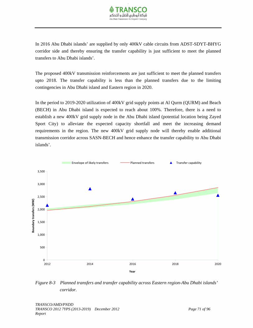
TRANSCO/AMD/PNDD TRANSCO 2012 7YPS (2013-2019) December 2012 Page 71 of 96 Report
In 2016 Abu Dhabi islands’ are supplied by only 400kV cable circuits from ADST-SDYT-BHYG
corridor side and thereby ensuring the transfer capability is just sufficient to meet the planned
transfers to Abu Dhabi islands’.
The proposed 400kV transmission reinforcements are just sufficient to meet the planned transfers
upto 2018. The transfer capability is less than the planned transfers due to the limiting
contingencies in Abu Dhabi island and Eastern region in 2020.
In the period to 2019-2020 utilization of 400kV grid supply points at Al Qurm (QURM) and Beach
(BECH) in Abu Dhabi island is expected to reach about 100%. Therefore, there is a need to
establish a new 400kV grid supply node in the Abu Dhabi island (potential location being Zayed
Sport City) to alleviate the expected capacity shortfall and meet the increasing demand
requirements in the region. The new 400kV grid supply node will thereby enable additional
transmission corridor across SASN-BECH and hence enhance the transfer capability to Abu Dhabi
islands’.
Figure 8-3 Planned transfers and transfer capability across Eastern region-Abu Dhabi islands’
corridor.
0
500
1,000
1,500
2,000
2,500
3,000
3,500
2012 2014 2016 2018 2020
Year
Bo
un
dar
y tr
ansf
ers
(MW
)
Envelope of likely transfers Planned transfers Transfer capability
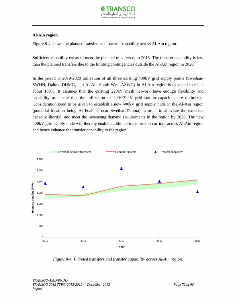
TRANSCO/AMD/PNDD TRANSCO 2012 7YPS (2013-2019) December 2012 Page 72 of 96 Report
Al-Ain region
Figure 8-4 shows the planned transfers and transfer capability across Al-Ain region.
Sufficient capability exists to meet the planned transfers upto 2018. The transfer capability is less
than the planned transfers due to the limiting contingencies outside the Al-Ain region in 2020.
In the period to 2019-2020 utilization of all three existing 400kV grid supply points (Sweihan-
SWHN; Dahma-DHMG, and Al-Ain South West-ASWG) in Al-Ain region is expected to reach
about 100%. It assumes that the existing 220kV mesh network have enough flexibility and
capability to ensure that the utilization of 400/132kV grid station capacities are optimized.
Consideration need to be given to establish a new 400kV grid supply node in the Al-Ain region
(potential location being Al Foah or near Sweihan/Dahma) in order to alleviate the expected
capacity shortfall and meet the increasing demand requirements in the region by 2020. The new
400kV grid supply node will thereby enable additional transmission corridor across Al-Ain region
and hence enhance the transfer capability to the region.
Figure 8-4 Planned transfers and transfer capability across Al-Ain region.
0
500
1,000
1,500
2,000
2,500
3,000
3,500
2012 2014 2016 2018 2020
Year
Bo
un
dar
y tr
ansf
ers (
MW
)
Envelope of likely transfers Planned transfers Transfer capability
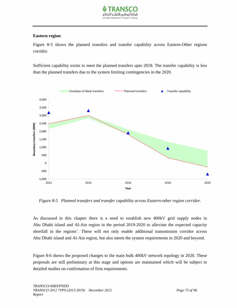
TRANSCO/AMD/PNDD TRANSCO 2012 7YPS (2013-2019) December 2012 Page 73 of 96 Report
Eastern region
Figure 8-5 shows the planned transfers and transfer capability across Eastern-Other regions
corridor.
Sufficient capability exists to meet the planned transfers upto 2018. The transfer capability is less
than the planned transfers due to the system limiting contingencies in the 2020.
Figure 8-5 Planned transfers and transfer capability across Eastern-other region corridor.
As discussed in this chapter there is a need to establish new 400kV grid supply nodes in
Abu Dhabi island and Al-Ain region in the period 2019-2020 to alleviate the expected capacity
shortfall in the regions’. These will not only enable additional transmission corridor across
Abu Dhabi island and Al-Ain region, but also meets the system requirements in 2020 and beyond.
Figure 8-6 shows the proposed changes to the main bulk 400kV network topology in 2020. These
proposals are still preliminary at this stage and options are maintained which will be subject to
detailed studies on confirmation of firm requirements.
‐1,000
‐500
0
500
1,000
1,500
2,000
2,500
3,000
3,500
4,000
2012 2014 2016 2018 2020
Year
Bo
un
dar
y tr
ansf
ers
(MW
)
Envelope of likely transfers Planned transfers Transfer capability
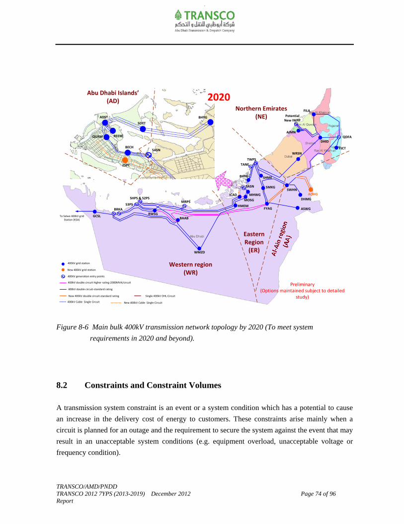
TRANSCO/AMD/PNDD TRANSCO 2012 7YPS (2013-2019) December 2012 Page 74 of 96 Report
Figure 8-6 Main bulk 400kV transmission network topology by 2020 (To meet system
requirements in 2020 and beyond).
8.2 Constraints and Constraint Volumes
A transmission system constraint is an event or a system condition which has a potential to cause
an increase in the delivery cost of energy to customers. These constraints arise mainly when a
circuit is planned for an outage and the requirement to secure the system against the event that may
result in an unacceptable system conditions (e.g. equipment overload, unacceptable voltage or
frequency condition).
2010 Best View (30GW)
ASWG
DHMG
SWHN
MOSG
SHME
WRSN
DHID
FILA
WMZD
SHPS & S2PS
QDFA
SASNBECH
QURM
ADST
REEM
SDYT
TWPS
ICAD
To Salwa 400kV grid Station (KSA)
GCSL
Abu Dhabi Islands’(AD)
Northern Emirates(NE)
Western region (WR)
TANE
SASN
Eastern Region
(ER)
BHYG
MHWG
BHYG
SMKG
AJMN
S3PS
RWSGBAAB
BRKA
MRPS
FYAGHMEM
400kV grid station
New 400kV grid station
400kV double circuit‐standard rating
New 400kV double circuit‐standard rating
400kV Cable Single Circuit
400kV generation entry points
400kV double circuit‐higher rating‐2000MVA/circuit
Single 400kV OHL Circuit
2020
AOHG
Preliminary(Options maintained subject to detailed
study)
FJCT
ZSPC
New 400kV Cable Single Circuit
Potential New IWPP

TRANSCO/AMD/PNDD TRANSCO 2012 7YPS (2013-2019) December 2012 Page 75 of 96 Report
Constraint measures provide an approximate quantification of risk for the identified known
constraints. Some of these constraints are imposed on the transmission system by the Users
plant/equipment design at the interfaces necessitating TRANSCO to take certain measures (e.g.
constraint generation or network re-arrangement) to ensure integrity of the power system is
maintained. It should be noted that only some of these constraints are non-compliant with the
security of supply standard and only those are potential candidates for the derogations.
Constraints and constraint volumes are quantified so that the Users can evaluate its impact on
themselves. It also informs the Users of current known constraints in the system and the
development plans to eliminate some of those constraints in the period to 2020.
Constraints/risks are grouped into three main categories namely:
Generation constraints.
Main interconnected transmission system constraints.
Demand supply exit points constraints.
8.2.1 Generation Constraints
This section summarizes major generation constraints and how these will be managed.
Constraint #G1: Generation constraint at TANE power station.
Users: a) Taweela Asia Power Company (TAPCO).
b) Gulf Total Tractebel Power Company (GTTPC).
TANE 400kV grid station is connected by 2x400kV overhead line circuits. The generation
connected at TANE 400kV grid station must be reduced to about 560MW (i.e. volume of
generation constraint about 475MW) for 400kV single-circuit outage or during line maintenance
period. The constraint is expected to be removed after reinforcing the TANE 400kV grid station
with an additional 400kV overhead line circuits in 2018.
TANE Power Station auxiliaries are fed through two generator transformer feeders (connected to
400kV bay 09 and 14) in TANE. Should one of those circuits be out of service total generation
from TANE Power Plant is required to be reduced to 560MW to maintain system integrity.
TRANSCO/AMD/PNDD TRANSCO 2012 7YPS (2013-2019) December 2012 Page 76 of 96 Report
Constraint#G2: Generation constraint at Taweela A1 power station.
User: Gulf Total Tractebel Power Company (GTTPC).
Taweela A1 power station auxiliaries are fed through two generator transformer feeders
(connected to 400kV bay 21 and bay 33 of TWPS). Should one of those circuits be out of service
total generation from Taweela A1 power station is required to be reduced to 560MW to maintain
system integrity (i.e. volume of generation constraint about 800MW).
Constraint#G3: High 132kV fault levels at Taweela-B 132kV bus.
User: Taweela Asia Power Company (TAPCO).
The Taweela-B 132kV bus is rated 40kA. The risk is managed by operating one 400/132kV
275MVA transformer in isolation (i.e. 132kV bus coupler open) or constraining generation
connected to Taweela-B 132kV bus. The volume of generation constraint is about 215MW.
Constraint#G4: High132kV fault levels at Fujairah Qidfa 132kV bus.
Users: a) Emirates SembCorp Water and Power Company (ESWPC).
b) Federal Electricity and Water Authority (FEWA).
The Fujairah Qidfa 132kV bus and Fujairah F1PS 132kV bus are rated 40kA. The risk is managed
by constraining the Fujairah F1 generation connected to Fujairah Qidfa 132kV bus and/or 132kV
bus at F1PS. The volume of generation constraint is about 240MW.
Constraint#G5: Generation constraint at Al-Ain power station (AAPS).
Users: a) Al-Mirfa Power Company (AMPC).
b) Al-Ain Distribution Company (AADC).
Restriction is placed on the operation of all generators connected to Toshiba 33kV switchgear of
AAPS due to short-circuit limitation at AAPS 33kV switchgear [for historical reasons Calor Emag
33kV switchgear rated 25kA; %Z of 220/33kV, 100MVA transformers connected to Toshiba 33kV
switchgear specified 13.6%]. The volume of generation constraint due to the above restriction is
70MW.

TRANSCO/AMD/PNDD TRANSCO 2012 7YPS (2013-2019) December 2012 Page 77 of 96 Report
A new 220/33kV grid station at AAPS is planned to be established by 2014 to meet the demand
growth in the region and provide additional capacity to offset decommissioning of existing
generation at AAPS planned after 2015.
8.2.2 Main Interconnected Transmission System Constraints
This section summarizes major main interconnected transmission system constraints and how these
will be managed.
Constraint#T1: High 400kV fault levels at 400kV bus in Taweela power station (TWPS).
The Taweela 400kV busbar is rated 63kA. This constraint is managed operationally by either
splitting the 400kV system in Abu Dhabi island i.e. opening 400kV cable circuits between ADST-
QURM or split the 400kV busbar at Taweela power station to ensure that the fault levels are within
acceptable levels.
Permanent mitigation measures are under consideration to eliminate high 400kV fault levels at
Taweela power station.
Constraint#T2: High probability of 400kV XLPE joint failures in Sas Al Nakheel-Beach corridor.
In the short-term the constraint is managed by establishing contingency operational measures such
as re-despatching the generation at Sas Al Nakheel/Umn Al Nar and re-arranging the 400kV
network at Taweela/Abu Dhabi island should a 400kV cable circuit contingency occurs between
Sas Al Nakheel-Beach corridor. The impact of this risk is to place a generation constraint of about
640MW at Sas Al Nakheel/Umn Al Nar for post N-1 (worst case).
A plan for the replacement of 400kV XLPE cable joints is currently under progress.
Constraint#T3: High 132kV fault levels in Sas Al Nakheel/Umn Al Nar Zone.
The impact of Umn Al Nar plant lifetime extension is that the 132kV fault levels at Umn Al Nar,
Sas Al Nakheel, Salt & Chlorine and Khalifa Park exceed their switchgear rating under certain
operating conditions when the generation at both Umn Al Nar and Sas Al Nakheel power stations
run at the same time. The risk is managed by opening the low voltage side of 400/132kV 500MVA
transformer at Sas Al Nakheel and/or constraining the generation connected to the Umn Al Nar
132kV bus among other measures such as splitting the downstream 132kV system, de-coupling the
220kV network at Umn Al Nar to ensure the 132kV fault levels are within acceptable limits.
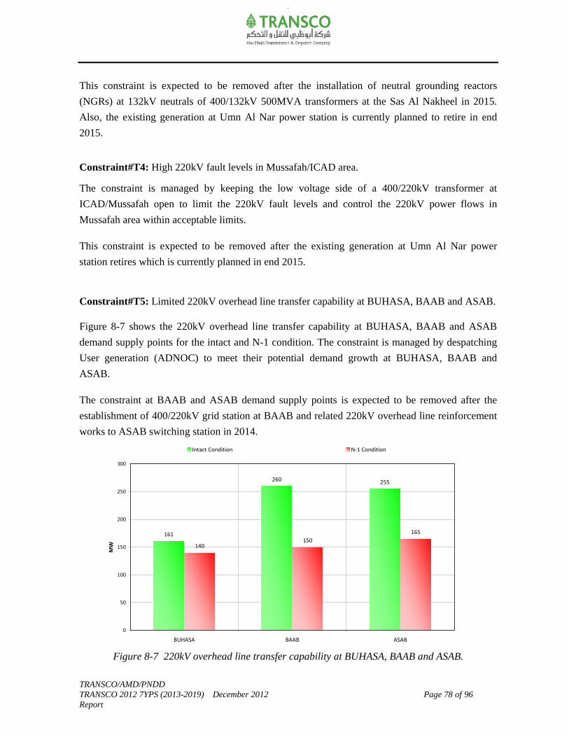
TRANSCO/AMD/PNDD TRANSCO 2012 7YPS (2013-2019) December 2012 Page 78 of 96 Report
161
260 255
140150
165
0
50
100
150
200
250
300
BUHASA BAAB ASAB
MW
Intact Condition N‐1 Condition
This constraint is expected to be removed after the installation of neutral grounding reactors
(NGRs) at 132kV neutrals of 400/132kV 500MVA transformers at the Sas Al Nakheel in 2015.
Also, the existing generation at Umn Al Nar power station is currently planned to retire in end
2015.
Constraint#T4: High 220kV fault levels in Mussafah/ICAD area.
The constraint is managed by keeping the low voltage side of a 400/220kV transformer at
ICAD/Mussafah open to limit the 220kV fault levels and control the 220kV power flows in
Mussafah area within acceptable limits.
This constraint is expected to be removed after the existing generation at Umn Al Nar power
station retires which is currently planned in end 2015.
Constraint#T5: Limited 220kV overhead line transfer capability at BUHASA, BAAB and ASAB.
Figure 8-7 shows the 220kV overhead line transfer capability at BUHASA, BAAB and ASAB
demand supply points for the intact and N-1 condition. The constraint is managed by despatching
User generation (ADNOC) to meet their potential demand growth at BUHASA, BAAB and
ASAB.
The constraint at BAAB and ASAB demand supply points is expected to be removed after the
establishment of 400/220kV grid station at BAAB and related 220kV overhead line reinforcement
works to ASAB switching station in 2014.
Figure 8-7 220kV overhead line transfer capability at BUHASA, BAAB and ASAB.
TRANSCO/AMD/PNDD TRANSCO 2012 7YPS (2013-2019) December 2012 Page 79 of 96 Report
Constraint#T6: 220/33kV grid stations supplied by two 220kV overhead line circuits.
The 220kV supplies to the following existing 220/33kV grid stations are currently supplied by two
220kV overhead line circuits. Under maintenance condition of a 220kV circuit, supplies to the
below mentioned 220/33kV grid stations will not be secured should the 2nd 220kV circuit trip.
Sila (SILA), Gaithy (GTHY), Baab (BAAB), Buhasa (BHSA), Asab (ASAB), Liwa (LIWA)
220/33kV grid stations in the Western region.
Mahawi (MHWG) and Samha (SMHG) 220/33kV grid stations in the Eastern region.
Al Hayer (AHYG), Maziyad (MZDG), Al Wagon (AWGG) and Umn Al Oush (OUSH) in the
Al-Ain region.
The above-mentioned 220/33kV grid stations are designed to a different standard attributed to the
legacy design wherein the economic case for reinforcing the above grid stations with additional
220kV overhead line circuits currently appears weak.
In the period to 2020:
Constraint at Baab (BAAB) and Asab (ASAB) will be relieved after the establishment of
400/220kV grid station at BAAB and related 220kV overhead line reinforcement works to
ASAB switching station in 2014.
Constraint at Mahawi (MHWG) will be relieved after the establishment of 400/132kV grid
station and 132/33kV substation at Mahawi in 2014.
8.2.3 Demand Supply Exit Point Constraints
The demand supply exit point constraints are grouped into primary and secondary. Primary
constraints are imposed on those exit points wherein the supplies are affected for N-1 which are
fed by single-circuit arrangements. Secondary constraints are imposed on those exit points wherein
the supplies are affected for N-1 attributed to the legacy design restrictions at the interfaces.
TRANSCO has identified that a number of presently energized sub-stations cannot be operated,
during times of peak demand, in a parallel arrangement. This limitation creates risk of demand loss
during time when the transformers at such sites are operated in independent mode. This operating
arrangement has arisen due to a mix of issues all of which are presently under review by
TRANSCO and Users. TRANSCO has committed to review and make recommendation to RSB
such that non-compliant sites are either derogated or modified to ensure compliance.

TRANSCO/AMD/PNDD TRANSCO 2012 7YPS (2013-2019) December 2012 Page 80 of 96 Report
40
27 31 35
22 23 24 25 27
0
1
2
3
4
5
6
7
8
9
10
2012 2013 2014 2015 2016 2017 2018 2019 2020
Year
Pri
mar
y Ex
it P
oin
t C
on
stra
ints
0
50
100
150
200
250
300
De
man
d (
MW
)
Total demand Maximum demand at risk Primary exit point constraints
TRANSCO has shared with RSB a list of all substation sites so affected and a programme of
works that will address short-term need. Once improved visibility exists as to the optimum long-
term solution for each site a further programme of works will be developed and shared with RSB.
The summary of demand supply exit point constraints is briefly described below:
Constraint#D1: Primary exit point constraints.
User: Abu Dhabi Distribution Company (ADDC).
Figure 8-8 shows the constraints measure profile for the primary exit points in the period 2012-
2020. Currently these constraints are located at Shamkha, Mafraq, Mussafah M12 and Raha Beach
area in the Mainland region; and at Liwa, Hameem (Qasr Al Sarab) and Qusahwira area in the
Western region.
Risk management and/or operational measures are in place to secure some of these supplies
through the ADDC distribution network back feed arrangements at these primary exit points
during the contingency scenario. Contingency arrangements for non-compliant network
arrangements are being established with Users of the transmission network. The extent of network
at risk post N-1 is deemed to be medium to group demand but would be classed as low if reflected
onto overall network demand. Derogations for these non-compliant arrangements are being
developed.
Figure 8-8 Primary exit point constraints measure.

TRANSCO/AMD/PNDD TRANSCO 2012 7YPS (2013-2019) December 2012 Page 81 of 96 Report
The constraints in Shamkha area (supplied by two 220/33kV temporary stations) are expected to
be removed after the establishment of Shamkha 400/132kV grid station and 132/33kV substation
in 2014/2015.
The constraints in Mafraq area (supplied by one 220/33kV temporary station) is expected to be
removed after the establishment of Mahawi 400/132kV grid station, 132/33kV substation at
Watbha, and 132/33kV substation at Nahda in 2014/2015.
The constraints in Mussafah M12 area (supplied by M12 132/11kV temporary station) is expected
to be removed after the establishment of Mahawi 400/132kV grid station and 132/11kV substation
at Mussafah M12 in 2014.
The constraints in Raha Beach area (supplied by Raha-A132/22kV substation) is expected to be
removed after the establishment of New Airport and Al Falah 132/22kV substations in 2013.
The 220kV single circuit overhead line arrangements at Liwa, Hameem (Qasr Al Sarab) and
Qusahwira area in the Western region are expected to be permanent as the economic case for
reinforcing these sites with additional 220kV overhead line circuits appears weak.
Constraint#D2: Secondary exit point constraints.
Users: a) Abu Dhabi Distribution Company (ADDC).
b) Al-Ain Distribution Company (AADC).
Figure 8-9 shows the constraints measure profile for the secondary exit points in the period 2012-
2020. These secondary constraints are imposed on those exit points wherein the supplies are
affected for N-1 attributed to the legacy design restrictions at the interfaces.
In the period to 2020 the constraints at the relevant secondary exit points will be removed as and
when the economic case justifies the reinforcement of those sites. Risk management and/or
operational measures are well understood within the sector to secure some of these supplies
through the User distribution network back feed arrangements at these secondary exit points during
the contingency scenario. The extent of network at risk post N-1 is deemed medium to group
demand but would be classed as low if reflected onto overall network demand.
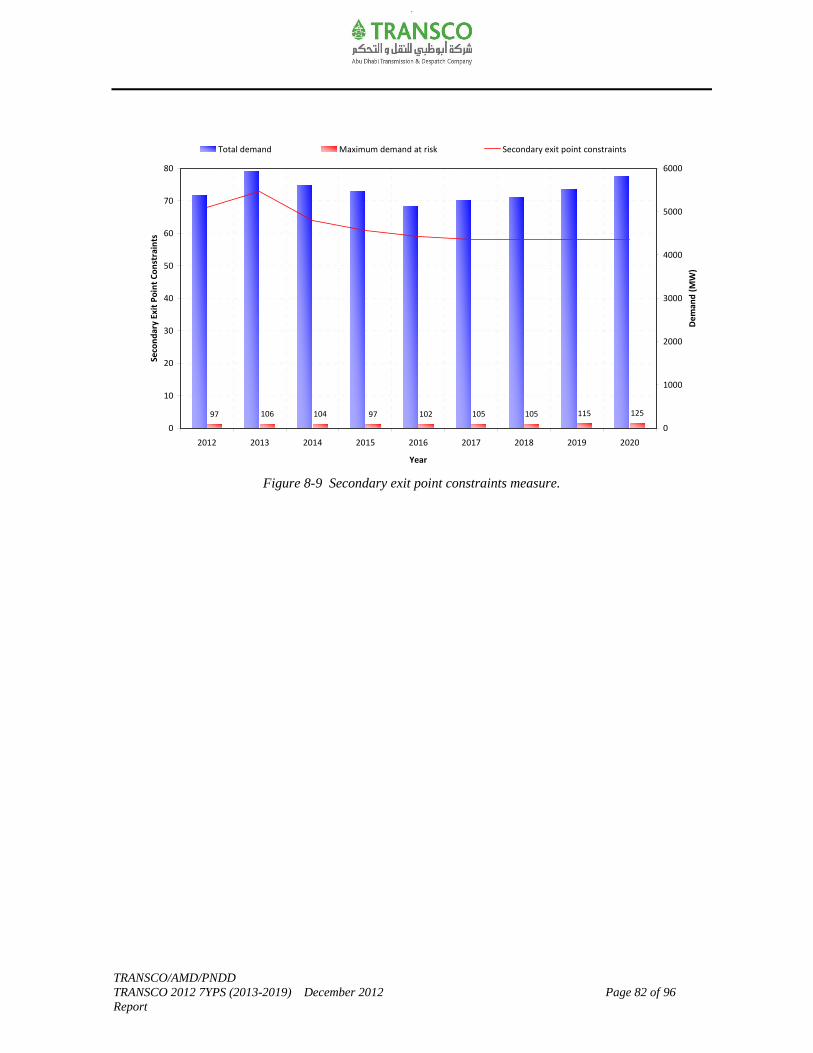
TRANSCO/AMD/PNDD TRANSCO 2012 7YPS (2013-2019) December 2012 Page 82 of 96 Report
97 106 104 97 102 105 105 115 125
0
10
20
30
40
50
60
70
80
2012 2013 2014 2015 2016 2017 2018 2019 2020
Year
Seco
nd
ary
Exit P
oin
t C
on
stra
ints
0
1000
2000
3000
4000
5000
6000
De
man
d (
MW
)
Total demand Maximum demand at risk Secondary exit point constraints
Figure 8-9 Secondary exit point constraints measure.

TRANSCO/AMD/PNDD TRANSCO 2012 7YPS (2013-2019) December 2012 Page 83 of 96 Report
9.0 Opportunities
One of the main purposes of the 7YPS is to enable the Users or any other entity seeking the use of
the transmission system, to identify and evaluate the most suitable opportunities available for
connection. Such opportunities shall be guided by the “Statement of Connection Charging
Methodology for the TRANSCO Electricity System” approved by the Bureau on November 26,
2005 to make a reasonable estimate of the charges to which they would be liable for the provision
of such services.
As a pre-requisite of identifying opportunities, there is a need to understand the transmission
system capabilities. An assessment of the main bulk 400kV transmission system capabilities gives
an indication the extent to which the system can accommodate the circumstances outside the
chosen likely best view planned transfers. The best view planned transfers are based on ADWEC’s
project-based demand forecast scenario. The planned transfers and capabilities across the
identified transmission boundaries is fully described in Chapter-4 and Chapter-8 respectively.
The generation capacity expansion plans and identification of potential new generation sites are
carried out by ADWEC/ADWEA Privatization Directorate. The ability to connect new potential
generation connections that requires the least electricity transmission reinforcement is the main
consideration given for the purpose of identifying the opportunities of this category. However,
other aspects such as technical, economical, environmental and the need for water production and
transmission among other policy directives are to be given due weighting in the selection of the
optimum generation site location.
9.1 Generation Connection Opportunities
The details of the existing and committed generation plants are presented in Chapter-3.
Figure 9-1 shows the existing and committed generation sites, and future potential site
opportunities for the new generation connections upto 2020.
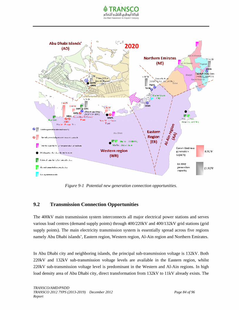
TRANSCO/AMD/PNDD TRANSCO 2012 7YPS (2013-2019) December 2012 Page 84 of 96 Report
Figure 9-1 Potential new generation connection opportunities.
9.2 Transmission Connection Opportunities
The 400kV main transmission system interconnects all major electrical power stations and serves
various load centres (demand supply points) through 400/220kV and 400/132kV grid stations (grid
supply points). The main electricity transmission system is essentially spread across five regions
namely Abu Dhabi islands’, Eastern region, Western region, Al-Ain region and Northern Emirates.
In Abu Dhabi city and neighboring islands, the principal sub-transmission voltage is 132kV. Both
220kV and 132kV sub-transmission voltage levels are available in the Eastern region, whilst
220kV sub-transmission voltage level is predominant in the Western and Al-Ain regions. In high
load density area of Abu Dhabi city, direct transformation from 132kV to 11kV already exists. The
Al-
Ain
reg
ion
(AA
)
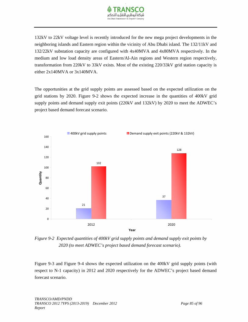
TRANSCO/AMD/PNDD TRANSCO 2012 7YPS (2013-2019) December 2012 Page 85 of 96 Report
132kV to 22kV voltage level is recently introduced for the new mega project developments in the
neighboring islands and Eastern region within the vicinity of Abu Dhabi island. The 132/11kV and
132/22kV substation capacity are configured with 4x40MVA and 4x80MVA respectively. In the
medium and low load density areas of Eastern/Al-Ain regions and Western region respectively,
transformation from 220kV to 33kV exists. Most of the existing 220/33kV grid station capacity is
either 2x140MVA or 3x140MVA.
The opportunities at the grid supply points are assessed based on the expected utilization on the
grid stations by 2020. Figure 9-2 shows the expected increase in the quantities of 400kV grid
supply points and demand supply exit points (220kV and 132kV) by 2020 to meet the ADWEC’s
project based demand forecast scenario.
Figure 9-2 Expected quantities of 400kV grid supply points and demand supply exit points by
2020 (to meet ADWEC’s project based demand forecast scenario).
Figure 9-3 and Figure 9-4 shows the expected utilization on the 400kV grid supply points (with
respect to N-1 capacity) in 2012 and 2020 respectively for the ADWEC’s project based demand
forecast scenario.
102
128
37
21
0
20
40
60
80
100
120
140
160
2012 2020
Year
Qu
anti
ty
400kV grid supply points Demand supply exit points (220kV & 132kV)
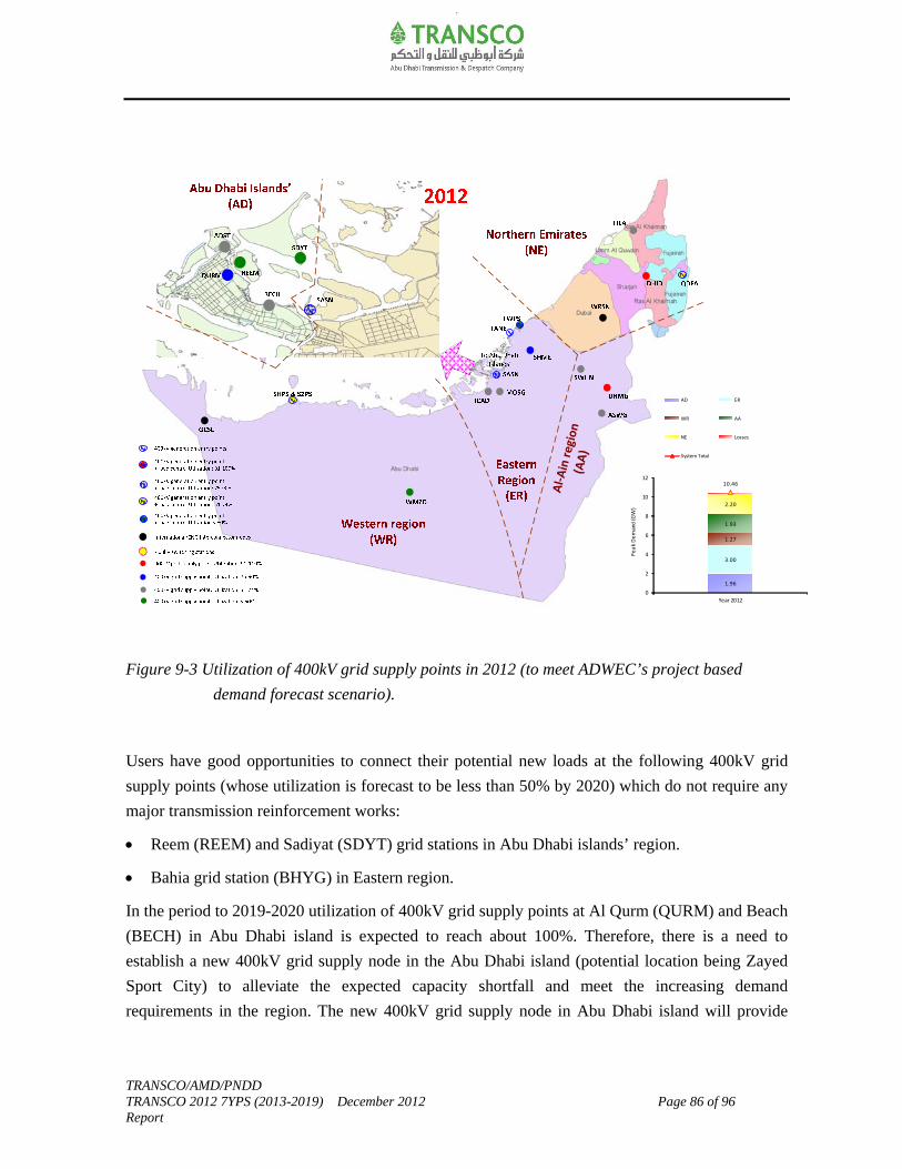
TRANSCO/AMD/PNDD TRANSCO 2012 7YPS (2013-2019) December 2012 Page 86 of 96 Report
Figure 9-3 Utilization of 400kV grid supply points in 2012 (to meet ADWEC’s project based
demand forecast scenario).
Users have good opportunities to connect their potential new loads at the following 400kV grid
supply points (whose utilization is forecast to be less than 50% by 2020) which do not require any
major transmission reinforcement works:
Reem (REEM) and Sadiyat (SDYT) grid stations in Abu Dhabi islands’ region.
Bahia grid station (BHYG) in Eastern region.
In the period to 2019-2020 utilization of 400kV grid supply points at Al Qurm (QURM) and Beach
(BECH) in Abu Dhabi island is expected to reach about 100%. Therefore, there is a need to
establish a new 400kV grid supply node in the Abu Dhabi island (potential location being Zayed
Sport City) to alleviate the expected capacity shortfall and meet the increasing demand
requirements in the region. The new 400kV grid supply node in Abu Dhabi island will provide
Al-
Ain
reg
ion
(AA
)1.96
3.00
1.27
1.93
2.20
10.46
0
2
4
6
8
10
12
Year 2012
Pe
ak
De
man
d (G
W)
AD ER
WR AA
NE Losses
System Total
TRANSCO/AMD/PNDD TRANSCO 2012 7YPS (2013-2019) December 2012 Page 87 of 96 Report
potential opportunity to connect new loads, enable additional transmission corridor across SASN-
BECH and hence enhance the transfer capability to Abu Dhabi islands’.
In addition to the identified demands in the period to 2020, consideration has also been given to
the potential new industrial demand growth in the Western and Eastern region to satisfy
ADWEC’s project based demand forecast scenario. Hence, the utilization of the following 400kV
grid supply points is forecast to be more than 90% with respect to their N-1 capacity:
Ruwais(RWSG), Baab(BAAB), Madinat Zayed(WMZD) & Mirfa(MRPS) in Western region.
Mussafah(MOSG), Industrial City of Abu Dhabi(ICAD) & Taweela(TWPS) in Eastern region.
400kV switching stations at Hameem (HMEM) and Al Faya (FYAG) are planned in the Eastern
region by 2020. These 400kV switching stations are required to enable additional transmission
corridors across West-East corridor to facilitate power evacuation from Braka nuclear power
plants, Shuweihat and Mirfa power plants; and improve the dynamic performance of the network.
Hence, these 400kV switching stations provide good opportunities to connect potential new
demands in the Mussafah/ICAD region and Shamkha/Al Faya region.
The utilization of the existing 400kV grid supply points at Sweihan (SWHN), Dahma (DHMG)
and Al-Ain South West (ASWG) in Al-Ain region is expected to reach 100% in the period 2020.
The total export commitments to the Northern Emirate (mainly FEWA and SEWA) are expected to
grow from about 2GW (in 2012) to reach about 5.4GW (in 2020). These export commitments are
satisfied by the existing and planned 400kV grid supply points at Dhaid (DHID), Fujairah-Qidfa
(QDFA), Ras Al Khaimah (FILA), New Fujairah City (FJCT), Ajman (AJMN).
To enable Abu Dhabi’s continued support to the energy requirements of the Northern Emirates and
meet any potential additional exports to systems outside of its authorized area and the need to
establish a new 400kV grid supply node in Al-Ain region to meet its demand growth will provide
good opportunities for major 400kV transmission reinforcement works in the regions in the period
2020.

TRANSCO/AMD/PNDD TRANSCO 2012 7YPS (2013-2019) December 2012 Page 88 of 96 Report
Figure 9-4 Utilization of 400kV grid supply points in 2020 (for ADWEC’s project based demand
forecast scenario).
Attachment-A contains the electricity demand forecast at the demand supply exit points for 2012-
2020 to meet ADWEC’s project based demand forecast scenario.
Attachment-B shows the electricity transmission network topology (400kV, 220kV and 132kV
system) for 2012-2020.
These Attachments gives full details of the opportunities available (in terms of location and
timeline) at the demand supply exit points for the Users or any other entity seeking the use of the
transmission system.
Al-
Ain
reg
ion
(AA
)
2.85
6.68
4.57
2.88
5.75
23.12
0
2
4
6
8
10
12
14
16
18
20
22
24
Year 2020
Pe
ak
De
man
d (G
W)
AD ER
WR AA
NE Losses
System Total
TRANSCO/AMD/PNDD TRANSCO 2012 7YPS (2013-2019) December 2012 Page 89 of 96 Report
10.0 Capital Programme and Delivery
Table 10-1 provides a high level summary of capital projects to meet the future demand growth
(load category) and replacement requirements (non-load category). These include the major on-
going, currently under tendering process and new planned power projects for the period 2013-
2020. It also includes a brief description of their needs/drivers for the identified projects/proposals
among other information.
It should be noted that some of the transmission schemes included in this 7YPS are still in the
early planning stage and options are kept open due to significant uncertainty in the demand-
generation backgrounds particularly from 2015 and beyond. Significant amount of work is still
required to be performed for those schemes. Hence, the requirements will be kept under review
taking into account any updates on the demand-generation background and network developments
before committing capital expenditure on those works. All options are maintained for possible
optimization and based on the chosen scheme option and updated requirements, the timing of the
related reinforcement works may be altered to ensure no regret solution.

S.N Budget CodeProject
StatusProject Name
Voltage level
(kV)
Connection
CategoryInitiative Category User Location Drivers/Needs
1 N7681 R 400kV OHL works for integrating Shuweihat S3 generation. 400 Entry Point Strategic Expansion SAPCO Western region For S3 IWPP generation integration.
2 N7680, N7681 R 400kV grid station at Ruwais, and related 400kV OHL works. 400 Exit Point Oil & Gas TAKREER Western region To meet Takreer demand requirements in Ruwais Industrial Area.
3 N5419, N5398‐A/B R 400kV cable works (2nd circuit) between ADST‐Sadiyat. 400 MITS Government Initiative TRANSCO Abu Dhabi Island To enable dismantling of 400kV OHL along the Abu Dhabi Island‐Sadiyat‐Bahia corridor.
4 N7137 R400kV 2nd interconnection cable works between TANE‐EMAL
Smelter.400 Entry Point Strategic Expansion EMAL Taweela To secure the back‐up supplies during "Secured Event" conditions in EMAL Smelter.
5 N6449, N6445 R 400/132kV grid station in Ajman and related 400kV OHL works. 400 Exit PointNorthern Emirates &
ExportsFEWA/ SEWA Ajman
6 N5629.1A, N5771‐01 R400/132kV grid station in New Fujairah City and related 400kV OHL
works.400 Exit Point
Northern Emirates &
ExportsFEWA Fujairah
7 N6318, N5424‐V01 R 400kV OHL works between Fujairah Qidfa and Ras Al Khaimah. 400 MITS Network Security TRANSCO Fujairah
8 N7056 R220kV GIS modification works at Madinat Zayed 400/220kV grid
Station.220 Entry Point Strategic Expansion MASDAR Western region To integrate Masdar CSP Shams‐1 Solar Plant.
9 N/A RIntegration of Masdar Noor‐1 PV Solar Plant at Sanaiya 220/33kV
grid station.220 Entry Point Strategic Expansion MASDAR Al‐Ain region To facilitate integration of Masdar Noor‐1 PV Solar Plant.
10 N11448, N11446 RNew 220kV switching station at ASAB and related 220kV OHL
works.220 Exit Point Oil & Gas
Al Hosn
Gas/ADCOWestern region To meet Al Hosn Gas/ADCO demand growth requirements in SHAH and ASAB.
11 N7015 R 220kV cable works between Dahma ‐ Zakher grid stations. 220 MITS Network Security TRANSCO Al‐Ain region To comply with network security.
12 N11762 T220kV GIS extension works and 3rd 220/33kV transformer at
Mezyad 220/33kV grid station. 220 Exit Point Growth AADC Al‐Ain region
To alleviate capacity shortfall in Maziyad 220/33kV grid station and meet the increasing
demand requirements in the area.
13 N11304 R 220kV OHL works for 1.8MMBD Project in Qusahwira. 220 Exit Point Oil & Gas ADCO Western region To meet demand requirements of ADCO’s 1.8MMBD Project in Qusahwira.
14 N2107‐01, N7148 R 220/33kV grid station at Ghantoot and related 220kV OHL works. 220 Exit Point Growth ADDC Eastern region To meet demand requirements in Ghantoot/Seih Al Sedaira (Al Ghadeer).
15 N5812.2A R 220/33kV temporary station at Al Faya. 220 Exit Point Growth ADDC Eastern regionTo meet initial demand requirements in Shamkha/Al Faya area until the establishment of
permanent supply source in the area.
16 N5629.1L (B), N5771‐02 R 132/33kV substation in Sudah Port and related 132kV OHL works. 132 Exit PointNorthern Emirates &
ExportsFEWA Fujairah
17 N5629.1E, N5771 R 132/33kV substation in Al Hayl and related 132kV OHL works. 132 Exit PointNorthern Emirates &
ExportsFEWA Fujairah
18 N8033, N11830 R New 132/33kV substation at Kalba and related 132kV OHL works. 132 Exit PointNorthern Emirates &
ExportsFEWA Fujairah
19 N7169, N6734 RNew 132/33kV substation at Khor Fakkan and related 132kV OHL
works.132 Exit Point
Northern Emirates &
ExportsFEWA Fujairah
20 N7203 R132/33kV transformers and related 33kV switchgear works at
Taweela‐A.132 Exit Point Economic Diversification ADDC Eastern region To meet initial demand growth in Khalifa Port and Industrial Zone.
Table 10‐1 High‐Level Summary of Year‐Wise Major Capital Power Projects (Load and Non‐Load Requirements) Expected to be Commissioned [Year 2013‐2020]
Year 2013
To meet the demand requirements of Northern Emirates and meet the statutory obligations of
ADWEA‐FEWA Agreement.
To meet the demand requirements in the mentioned areas and support the export
commitments agreed between ADWEA and FEWA.
TRANSCO/AMD/PNDD
TRANSCO 2012 7YPS (2013‐2019) December 2012
Report Page 90 of 96

S.N Budget CodeProject
StatusProject Name
Voltage level
(kV)
Connection
CategoryInitiative Category User Location Drivers/Needs
Table 10‐1 High‐Level Summary of Year‐Wise Major Capital Power Projects (Load and Non‐Load Requirements) Expected to be Commissioned [Year 2013‐2020]
21 N7133, N7097 R132/11kV substation in Sir Baniyas Island and related 132kV cable
works.132
Entry & Exit
PointStrategic Expansion ADDC Western region To meet demand growth in Sir Baniyas Island and facilitate integration of Masdar Wind Farm.
22 N6166.1 LotD, N6755 R 132/11kV substation at ADNEC and related 132kV cable works. 132 Exit Point Growth ADDC Abu Dhabi IslandTo meet ADNEC development demands and relieve loading on the existing 132/11kV
substations within the vicinity (EMBS & GLFA).
23 N7204 LotD, N7144‐A R132/11kV substation for Presidential Palace and related 132kV
cable works.132 Exit Point Growth ADDC Abu Dhabi Island To meet Presidential palace demand requirements.
24 N6166.1 Lot B, N6755 R132/22kV substation at New Airport and related 132kV cable
works.132 Exit Point Growth ADDC Eastern Region To meet Airport demand requirements.
25 N7204.1 Lot E, N6755 R 132/22kV substation at Al Falah and related 132kV cable works. 132 Exit Point Growth ADDC Eastern RegionTo meet demand requirements related to Al Falah Community development and in the vicinity
area of Shamkha.
26N6166.1 Lot E, N6755,
N7144‐BR
132/22kV substation at Capital District and related 132kV cable
works.132 Exit Point Growth ADDC Eastern Region To meet demand requirements in Capital District.
27N6166.1 LotC; N6755,
N7144‐BR 132/11kV substation at Khalifa C and related 132kV cable works. 132 Exit Point Growth ADDC Eastern Region
To meet demand requirements in Khalifa and vicinity area related to Watani, golf club, golf
gardens and Abu Dhabi shooting club developments.
28 N7022 R132kV cable interconnection works between 132kV substations in
TMUH (Reem Island) and SOWA (Suwa Island).132 MITS Network Security TRANSCO
Reem and Suwa
IslandsTo comply with network security.
1N4611‐1A/B, N4611‐1A V01,
N10920, N4906‐V04R 400/132kV grid station at Bahia and related 400kV OHL works. 400 MITS Growth TRANSCO Eastern region
Provide 132kV supply source to the existing substations in Bahia, Yas Island and Raha Beach
(Raha‐A & Raha‐B) and planned substations in Al Falah and Airport areas; enabling ganging of
400kV OHL/cable circuits across Taweela‐TANE‐Bahia‐Sadiyat corridor and facilitate power
evacuation from TANE generation.
2 N7055, N7906 R400kV cable works between Bahia and Sadiyat grid stations. Work
stage programme through 2014‐2016.400 MITS Government Initiative TRANSCO Eastern region To enable dismantling of 400kV OHL along the Abu Dhabi Island‐Sadiyat‐Bahia corridor.
3 N10920 T400kV Shunt Reactors at Bahia and Sadiyat. Work stage
programme through 2014‐2016.400 MITS Network Security TRANSCO Eastern region
a) Required for MVAr compensation due to long and increased 400kV cables circuits in
TRANSCO network b) For stabilization and voltage control under light load conditions c)
Achieve lower line losses.
4 N6462.A R 400/132kVgrid station in Mahawi. 400 MITS Growth TRANSCO Eastern region
5 N6524, N6462.B, N6462.C R
400kV cable works between Sas Al Nakheel and Mahawi (2
circuits); and between Mahawi and Mussafah (3 circuits) ‐ Works
stage programme through 2014‐2016.
400 MITS Government Initiative TRANSCO Eastern region
6 N7110, N7150 R 400/132kV grid station at Shamkha and related 400kV OHL works. 400 MITS Growth TRANSCO Eastern region
a) Provide 132kV supply source to the planned substations in Shamkha, South Shamkha and Al
Faya b) Provide 132kV back‐up supply source to Falah 132kV substation. c) Avoid short term
investments that would have been required to reinforce the existing 220kV network to
eliminate the current network arrangement that is non‐compliant with TRANSCO’s security of
supply License obligations and its associated loss of supply risk as a result of supplying loads by
non‐secure single circuit 220/33kV substations. d) Strengthen 400kV system backbone and
enable additional transmission corridors across West‐East.
7 N12037 T 400kV OHL works between Ruwais and Baab grid stations. 400 MITS Strategic Expansion TRANSCO Western regionTo facilitate power evacuation from Shuweihat S3 generation and enhance the transfer
capability across West‐East corridor.
8 N11447, N11443, N11446 R400/220/33kV grid station at Baab and related 400kV OHL and
220kV OHL works.400, 220 MITS Oil & Gas TRANSCO Western region
Provide 400kV source to meet ADNOC group demand growth in BAAB, BUHASA, ASAB and
SHAH area; and enhance 220kV overhead line transfer capability in the regions.
Year 2014
a) Provide 132kV supply source to the planned substations in Mohammed Bin Zayed City,
Mussafah M12, Mafraq, Nahda and Capital District. b) Facilitate transfer of existing Mussafah
132kV substation to Mahawi Zone. c) Facilitate dismantling of existing 220/33kV grid stations
in Mahawi and Watbha and conversion of the same to 132/33kV substations. d) Enable
dismantling 400kV and 220kV OHL along Sas Al Nakheel‐Mahawi‐Mussafah corridor.
TRANSCO/AMD/PNDD
TRANSCO 2012 7YPS (2013‐2019) December 2012
Report Page 91 of 96
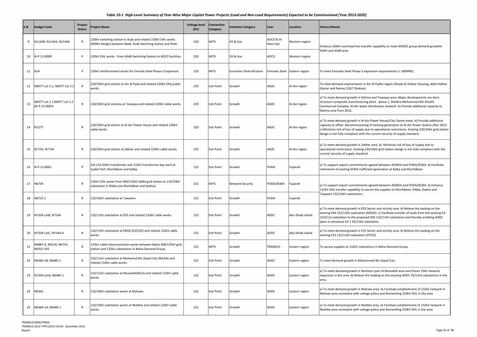
S.N Budget CodeProject
StatusProject Name
Voltage level
(kV)
Connection
CategoryInitiative Category User Location Drivers/Needs
Table 10‐1 High‐Level Summary of Year‐Wise Major Capital Power Projects (Load and Non‐Load Requirements) Expected to be Commissioned [Year 2013‐2020]
9 N11448, N11443, N11446 R220kV switching station in Asab and related 220kV OHL works
(400kV design) between Baab, Asab Switching station and Shah.220 MITS Oil & Gas
ADCO & Al
Hosn GasWestern region
10 N‐P‐13‐0009 P 220kV OHL works ‐ from ASAB Switching Station to ADCO facilities. 220 MITS Oil & Gas ADCO Western region
11 N/A P 220kV reinforcement works for Emirate Steel Phase‐3 Expansion. 220 MITS Economic Diversification Emirates Steel Eastern region To meet Emirates Steel Phase‐3 expansion requirements (> 300MW).
12 N6977 Lot 2.1, N6977 Lot 2.2 R220/33kV grid station at Ain Al Fyda and related 220kV OHL/cable
works.220 Exit Point Growth AADC Al‐Ain region
To meet demand requirements in Ain Al Fydha region (Shaab Al Ashkar Housing, Jebel Hafeet
Glacier and Naima (1267 Shabias).
13N6977 Lot 1.1,N6977 Lot 1.2
(N‐P‐13‐0007)R 220/33kV grid stations at Towayya and related 220kV cable works. 220 Exit Point Growth AADC Al‐Ain region
a) To meet demand growth in Dahma and Towayya area. Major developments are Aero
structure composite manufacturing plant ‐ phase 1, Sheikha Mohammed Bin Khalifa
Commercial Complex, Al‐Ain water distribution network. b) Provide additional capacity to
Dahma area from 2016.
14 N7277 R220/33kV grid station at Al‐Ain Power House and related 220kV
cable works.220 Exit Point Growth AADC Al‐Ain region
a) To meet demand growth in Al‐Ain Power House/City Centre areas. b) Provide additional
capacity to offset decommissioning of existing generation at Al‐Ain Power Station after 2015.
c) Minimize risk of loss of supply due to operational restrictions. Existing 220/33kV grid station
design is not fully compliant with the current security of supply standard.
15 N7733, N7734 R 220/33kV grid station at Zakher and related 220kV cable works. 220 Exit Point Growth AADC Al‐Ain region
a) To meet demand growth in Zakher area. b) Minimize risk of loss of supply due to
operational restrictions. Existing 220/33kV grid station design is not fully compliant with the
current security of supply standard.
16 N‐P‐13‐0001 P3rd 132/33kV transformer and 132kV transformer bay each at
Sudah Port, Khorfakkan and Kalba.132 Exit Point Growth FEWA Fujairah
a) To support export commitments agreed between ADWEA and FEWA/SEWA. b) Facilitate
retirement of existing SEWA inefficient generation at Kalba and Khorfakkan.
17 N6734 R132kV OHL works from 400/132kV Qidfa grid station to 132/33kV
substation in Dibba (via Khorfakkan and Dadna).132 MITS Network Security FEWA/SEWA Fujairah
18 N6725.1 R 132/33kV substation at Tawyeen. 132 Exit Point Growth FEWA Fujairah
19 N7204 LotB, N7144 R 132/11kV substation at E03 and related 132kV cable works. 132 Exit Point Growth ADDC Abu Dhabi Island
a) To meet demand growth in E03 Sector and vicinity area. b) Relieve the loading on the
existing E04 132/11kV substation (MDZD). c) Facilitate transfer of loads from the existing E4‐
1(33/11) substation to the proposed E03 132/11kV substation and thereby enabling ADDC
plans to phaseout E4‐1 33/11kV substation.
20 N7204 LotC, N7144‐A R132/11kV substation at EROD (E25/02) and related 132kV cable
works.132 Exit Point Growth ADDC Abu Dhabi Island
a) To meet demand growth in E25 Sector and vicinity area. b) Relieve the loading on the
existing E25 132/11kV substation (HTCO).
21N4887‐A, N6526, N6755,
N4352 V01R
132kV cable interconnection works between Bahia 400/132kV grid
station and 132kV substations in Bahia Demand Group. 132 MITS Growth TRANSCO Eastern region To secure supplies to 132kV substations in Bahia Demand Group.
22 N6384‐1B, N6485.1 R132/11kV substation at Mohamed Bin Zayed City (MCAA) and
related 132kV cable works.132 Exit Point Growth ADDC Eastern region To meet demand growth in Mohammed Bin Zayed City.
23 N7204‐LotA, N6485.1 R132/11kV substation at Mussafah(M12) and related 132kV cable
works.132 Exit Point Growth ADDC Eastern region
a) To meet demand growth in Northern part of Mussafah area and freeze 33kV network
expansion in the area. b) Relieve the loading on the existing ADDC 33/11kV substations in the
area.
24 N6362 R 132/33kV substation works at Mahawi. 132 Exit Point Growth ADDC Eastern regiona) To meet demand growth in Mahawi area. b) Facilitate establishment of 132kV network in
Mahawi area consistent with voltage policy and dismantling 220kV OHL in the area.
25 N6384‐1A, N6485.1 R132/33kV substation works at Watbha and related 132kV cable
works.132 Exit Point Growth ADDC Eastern region
a) To meet demand growth in Watbha area. b) Facilitate establishment of 132kV network in
Watbha area consistent with voltage policy and dismantling 220kV OHL in the area.
Enhance 220kV overhead line transfer capability to meet ADNOC group demand growthin
SHAH and ASAB area.
a) To support export commitments agreed between ADWEA and FEWA/SEWA. b) Enhance
132kV OHL transfer capability to secure the supplies to Khorfakkan, Dibba, Dadna and
Tawyeen 132/33kV substations.
TRANSCO/AMD/PNDD
TRANSCO 2012 7YPS (2013‐2019) December 2012
Report Page 92 of 96
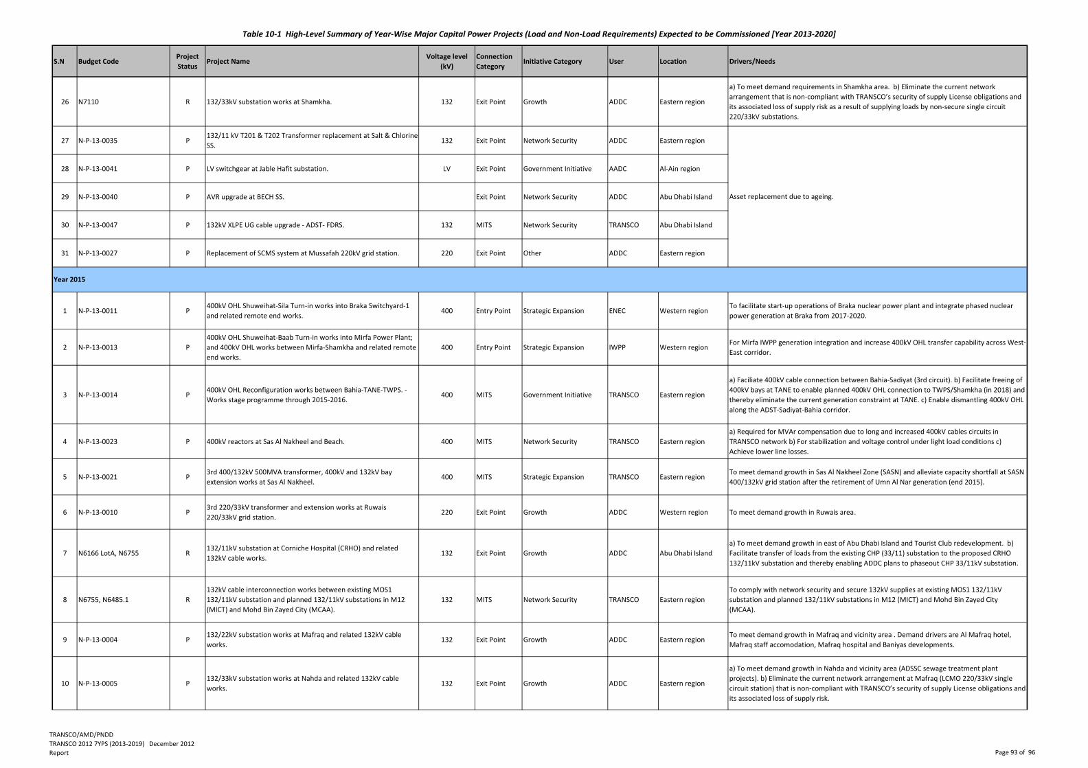
S.N Budget CodeProject
StatusProject Name
Voltage level
(kV)
Connection
CategoryInitiative Category User Location Drivers/Needs
Table 10‐1 High‐Level Summary of Year‐Wise Major Capital Power Projects (Load and Non‐Load Requirements) Expected to be Commissioned [Year 2013‐2020]
26 N7110 R 132/33kV substation works at Shamkha. 132 Exit Point Growth ADDC Eastern region
a) To meet demand requirements in Shamkha area. b) Eliminate the current network
arrangement that is non‐compliant with TRANSCO’s security of supply License obligations and
its associated loss of supply risk as a result of supplying loads by non‐secure single circuit
220/33kV substations.
27 N‐P‐13‐0035 P132/11 kV T201 & T202 Transformer replacement at Salt & Chlorine
SS.132 Exit Point Network Security ADDC Eastern region
28 N‐P‐13‐0041 P LV switchgear at Jable Hafit substation. LV Exit Point Government Initiative AADC Al‐Ain region
29 N‐P‐13‐0040 P AVR upgrade at BECH SS. Exit Point Network Security ADDC Abu Dhabi Island
30 N‐P‐13‐0047 P 132kV XLPE UG cable upgrade ‐ ADST‐ FDRS. 132 MITS Network Security TRANSCO Abu Dhabi Island
31 N‐P‐13‐0027 P Replacement of SCMS system at Mussafah 220kV grid station. 220 Exit Point Other ADDC Eastern region
1 N‐P‐13‐0011 P400kV OHL Shuweihat‐Sila Turn‐in works into Braka Switchyard‐1
and related remote end works. 400 Entry Point Strategic Expansion ENEC Western region
To facilitate start‐up operations of Braka nuclear power plant and integrate phased nuclear
power generation at Braka from 2017‐2020.
2 N‐P‐13‐0013 P
400kV OHL Shuweihat‐Baab Turn‐in works into Mirfa Power Plant;
and 400kV OHL works between Mirfa‐Shamkha and related remote
end works.
400 Entry Point Strategic Expansion IWPP Western regionFor Mirfa IWPP generation integration and increase 400kV OHL transfer capability across West‐
East corridor.
3 N‐P‐13‐0014 P400kV OHL Reconfiguration works between Bahia‐TANE‐TWPS. ‐
Works stage programme through 2015‐2016.400 MITS Government Initiative TRANSCO Eastern region
a) Faciliate 400kV cable connection between Bahia‐Sadiyat (3rd circuit). b) Facilitate freeing of
400kV bays at TANE to enable planned 400kV OHL connection to TWPS/Shamkha (in 2018) and
thereby eliminate the current generation constraint at TANE. c) Enable dismantling 400kV OHL
along the ADST‐Sadiyat‐Bahia corridor.
4 N‐P‐13‐0023 P 400kV reactors at Sas Al Nakheel and Beach. 400 MITS Network Security TRANSCO Eastern region
a) Required for MVAr compensation due to long and increased 400kV cables circuits in
TRANSCO network b) For stabilization and voltage control under light load conditions c)
Achieve lower line losses.
5 N‐P‐13‐0021 P3rd 400/132kV 500MVA transformer, 400kV and 132kV bay
extension works at Sas Al Nakheel. 400 MITS Strategic Expansion TRANSCO Eastern region
To meet demand growth in Sas Al Nakheel Zone (SASN) and alleviate capacity shortfall at SASN
400/132kV grid station after the retirement of Umn Al Nar generation (end 2015).
6 N‐P‐13‐0010 P3rd 220/33kV transformer and extension works at Ruwais
220/33kV grid station.220 Exit Point Growth ADDC Western region To meet demand growth in Ruwais area.
7 N6166 LotA, N6755 R132/11kV substation at Corniche Hospital (CRHO) and related
132kV cable works.132 Exit Point Growth ADDC Abu Dhabi Island
a) To meet demand growth in east of Abu Dhabi Island and Tourist Club redevelopment. b)
Facilitate transfer of loads from the existing CHP (33/11) substation to the proposed CRHO
132/11kV substation and thereby enabling ADDC plans to phaseout CHP 33/11kV substation.
8 N6755, N6485.1 R
132kV cable interconnection works between existing MOS1
132/11kV substation and planned 132/11kV substations in M12
(MICT) and Mohd Bin Zayed City (MCAA).
132 MITS Network Security TRANSCO Eastern region
To comply with network security and secure 132kV supplies at existing MOS1 132/11kV
substation and planned 132/11kV substations in M12 (MICT) and Mohd Bin Zayed City
(MCAA).
9 N‐P‐13‐0004 P132/22kV substation works at Mafraq and related 132kV cable
works.132 Exit Point Growth ADDC Eastern region
To meet demand growth in Mafraq and vicinity area . Demand drivers are Al Mafraq hotel,
Mafraq staff accomodation, Mafraq hospital and Baniyas developments.
10 N‐P‐13‐0005 P132/33kV substation works at Nahda and related 132kV cable
works.132 Exit Point Growth ADDC Eastern region
a) To meet demand growth in Nahda and vicinity area (ADSSC sewage treatment plant
projects). b) Eliminate the current network arrangement at Mafraq (LCMO 220/33kV single
circuit station) that is non‐compliant with TRANSCO’s security of supply License obligations and
its associated loss of supply risk.
Asset replacement due to ageing.
Year 2015
TRANSCO/AMD/PNDD
TRANSCO 2012 7YPS (2013‐2019) December 2012
Report Page 93 of 96

S.N Budget CodeProject
StatusProject Name
Voltage level
(kV)
Connection
CategoryInitiative Category User Location Drivers/Needs
Table 10‐1 High‐Level Summary of Year‐Wise Major Capital Power Projects (Load and Non‐Load Requirements) Expected to be Commissioned [Year 2013‐2020]
11 N‐P‐13‐0006 P132/22kV substation works at South Shamkha and related 132kV
cable works.132 Exit Point Growth ADDC Eastern region
a) To meet demand growth in South Shamkha and vicinity area.b) Eliminate the current
network arrangement at Shamkha (1SMK & 2SMK 220/33kV single circuit stations) that is non‐
compliant with TRANSCO’s security of supply License obligations and its associated loss of
supply risk.
12 N‐P‐13‐0017 P132kV cable interconnection works between Shamkha and Falah
132kV substations.132 MITS Network Security TRANSCO Eastern region Comply with network security.
13 N‐P‐13‐0016 P
132kV cable reconfiguration between SLTC and JSRN 132/11kV
substations; decommission 132kV cable circuits between Old
Mushrif (MSXX)‐Mussafah and Old Mushrif (MSXX)‐Umn Al Nar.
132 MITS Network Security TRANSCO Eastern region
To facilitate use of existing 132kV bays at MOS1 132/11kV substation for connecting planned
132kV cable circuits from 132kV substations (MICT and MCAA) i.e. enable completion of 132kV
cable works related to contracts N6755, N6485.1.
14 N‐P‐13‐0015 P132kV cable interconnection works between Reem Island and Abu
Dhabi Island.132 MITS Network Security TRANSCO
Abu Dhabi Island &
Reem/Suwa Island
a) Delay the need for new 400/132kV grid station in Abu Dhabi Island b) Free up 132kV bays at
ADST and QURM grid stations which can be used to supply new loads in their respective 132kV
zones. c) Fully utilize the available capacity of REEM 400/132kV grid station d) Provide
operational flexibility and facilitates load transfers between REEM and ADST/QURM grid
station zones through the establishment of few inter‐zone 132kV normal open points during
emergency.
15 N‐P‐13‐0034 P132/11 kV T201 & T202 transformer replacement at Embassy
substation (W59).132 Exit Point Network Security ADDC Abu Dhabi Island
16 N‐P‐13‐0036 PBus bar Protection (INX2 & SX109) Upgrade at Various Sites:UNPS‐
132kV, MOS1‐132, UNPS‐220, AAPS‐220.220 & 132 Exit Point Network Security ADDC & AADC Eastern region
17 N‐P‐13‐0038 PFeeder protection upgrade at various sites: 220‐WATH‐SHME,
WATH‐KHZG, TCLB‐ADST, SHME &TWPS.400, 220 & 132 MITS Network Security TRANSCO Various regions
18 N‐P‐13‐0042 P FMS Upgrade at KHALIDYA 132/11kV substation (W09). 132 Exit Point Network Security ADDC Abu Dhabi Island
19 N‐P‐13‐0044 P SVC cooling and control system upgrade at AAPS, ASWG and MOS. 220 Exit Point Network Security TRANSCOEastern & Al‐Ain
region
20 TBA P 220kV Ruwais‐Sila OPGW Rehabilitation works. 220 MITS Network Security TRANSCO Western region
21 N‐P‐13‐0028 P Taweelah Mimic Panel Replacement. Other Eastern region
1 N‐P‐13‐0012 P400kV OHL works between Braka Switchyard‐1 and Ruwais grid
stations.400 Entry Point Strategic Expansion ENEC Western region To facilitate power evacuation from Braka nuclear power plant.
2 N‐P‐13‐0022 P400kV cable works (3rd circuit) between ADSTand Sadiyat grid
stations.400 MITS Government Initiative TRANSCO Eastern region
Enhance power transfer capability between ADST‐Sadiyat‐Bahia corridor and comply with
network security.
3 TBA P400kV OHL works between Shamkha and Sweihan and related
remote end works; 400kV extension works at Sweihan.400 MITS Strategic Expansion TRANSCO Eastern region Facilitate power evacuation from West to East Corridor.
4 N‐P‐13‐0021 P
3rd 220/33kV transformer and extension works at Al Foah
220/33kV grid station, and retrofit NGRs to 220/33kV transformers
at various 220/33kV grid stations in Al‐Ain region.
220 Exit PointGrowth & Network
SecurityAADC Al‐Ain region
a) To meet demand growth in Al Faoh area. b) Reduce single‐phase 33kV fault levels at
selective 220/33kV grid stations.
5 N‐P‐13‐0025 PConversion of 220kV equipment to indoor and retrofit NGRs to
220/33kV transformers at Al Wagon.220 Exit Point Replacement AADC Al‐Ain region
a) Visual aminity and comply with existing practice of establishing indoor substation to protect
against environmental pollution b) Reduce single‐phase 33kV fault levels.
6 N‐P‐13‐0018 PSVC baising at Al‐Ain South West and Mussafah 220/33kV grid
stations.220 MITS Network Security TRANSCO
Al‐Ain and Eastern
region
a) To provide dynamic reactive power compensation. b) Additional reactive power
compensation to off‐set the existing SVCs at Al Ain Power House which is coming to the end of
their useful life.
Year 2016
Asset replacement due to ageing.
TRANSCO/AMD/PNDD
TRANSCO 2012 7YPS (2013‐2019) December 2012
Report Page 94 of 96
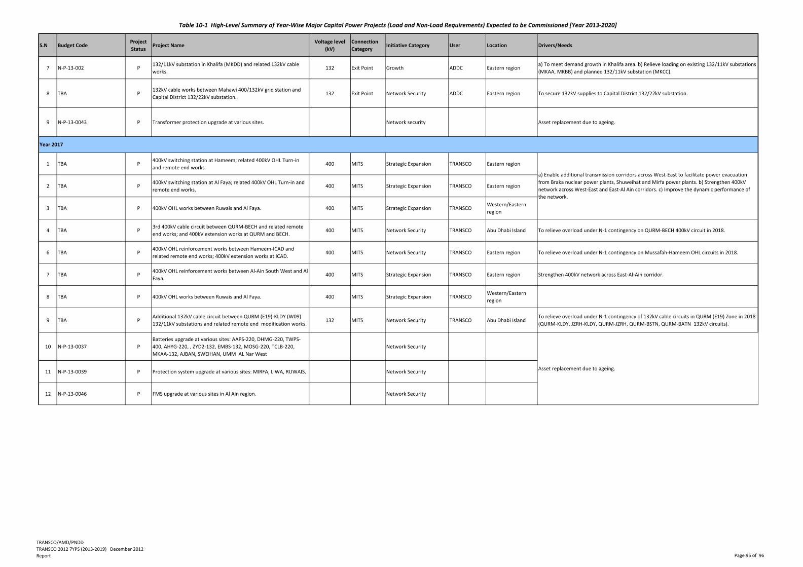
S.N Budget CodeProject
StatusProject Name
Voltage level
(kV)
Connection
CategoryInitiative Category User Location Drivers/Needs
Table 10‐1 High‐Level Summary of Year‐Wise Major Capital Power Projects (Load and Non‐Load Requirements) Expected to be Commissioned [Year 2013‐2020]
7 N‐P‐13‐002 P132/11kV substation in Khalifa (MKDD) and related 132kV cable
works.132 Exit Point Growth ADDC Eastern region
a) To meet demand growth in Khalifa area. b) Relieve loading on existing 132/11kV substations
(MKAA, MKBB) and planned 132/11kV substation (MKCC).
8 TBA P132kV cable works between Mahawi 400/132kV grid station and
Capital District 132/22kV substation.132 Exit Point Network Security ADDC Eastern region To secure 132kV supplies to Capital District 132/22kV substation.
9 N‐P‐13‐0043 P Transformer protection upgrade at various sites. Network security Asset replacement due to ageing.
1 TBA P400kV switching station at Hameem; related 400kV OHL Turn‐in
and remote end works.400 MITS Strategic Expansion TRANSCO Eastern region
2 TBA P400kV switching station at Al Faya; related 400kV OHL Turn‐in and
remote end works. 400 MITS Strategic Expansion TRANSCO Eastern region
3 TBA P 400kV OHL works between Ruwais and Al Faya. 400 MITS Strategic Expansion TRANSCOWestern/Eastern
region
4 TBA P3rd 400kV cable circuit between QURM‐BECH and related remote
end works; and 400kV extension works at QURM and BECH.400 MITS Network Security TRANSCO Abu Dhabi Island To relieve overload under N‐1 contingency on QURM‐BECH 400kV circuit in 2018.
6 TBA P400kV OHL reinforcement works between Hameem‐ICAD and
related remote end works; 400kV extension works at ICAD.400 MITS Network Security TRANSCO Eastern region To relieve overload under N‐1 contingency on Mussafah‐Hameem OHL circuits in 2018.
7 TBA P400kV OHL reinforcement works between Al‐Ain South West and Al
Faya.400 MITS Strategic Expansion TRANSCO Eastern region Strengthen 400kV network across East‐Al‐Ain corridor.
8 TBA P 400kV OHL works between Ruwais and Al Faya. 400 MITS Strategic Expansion TRANSCOWestern/Eastern
region
9 TBA PAdditional 132kV cable circuit between QURM (E19)‐KLDY (W09)
132/11kV substations and related remote end modification works.132 MITS Network Security TRANSCO Abu Dhabi Island
To relieve overload under N‐1 contingency of 132kV cable circuits in QURM (E19) Zone in 2018
(QURM‐KLDY, JZRH‐KLDY, QURM‐JZRH, QURM‐BSTN, QURM‐BATN 132kV circuits).
10 N‐P‐13‐0037 P
Batteries upgrade at various sites: AAPS‐220, DHMG‐220, TWPS‐
400, AHYG‐220, , ZYD2‐132, EMBS‐132, MOSG‐220, TCLB‐220,
MKAA‐132, AJBAN, SWEIHAN, UMM AL Nar West
Network Security
11 N‐P‐13‐0039 P Protection system upgrade at various sites: MIRFA, LIWA, RUWAIS. Network Security
12 N‐P‐13‐0046 P FMS upgrade at various sites in Al Ain region. Network Security
Asset replacement due to ageing.
Year 2017
a) Enable additional transmission corridors across West‐East to facilitate power evacuation
from Braka nuclear power plants, Shuweihat and Mirfa power plants. b) Strengthen 400kV
network across West‐East and East‐Al Ain corridors. c) Improve the dynamic performance of
the network.
TRANSCO/AMD/PNDD
TRANSCO 2012 7YPS (2013‐2019) December 2012
Report Page 95 of 96
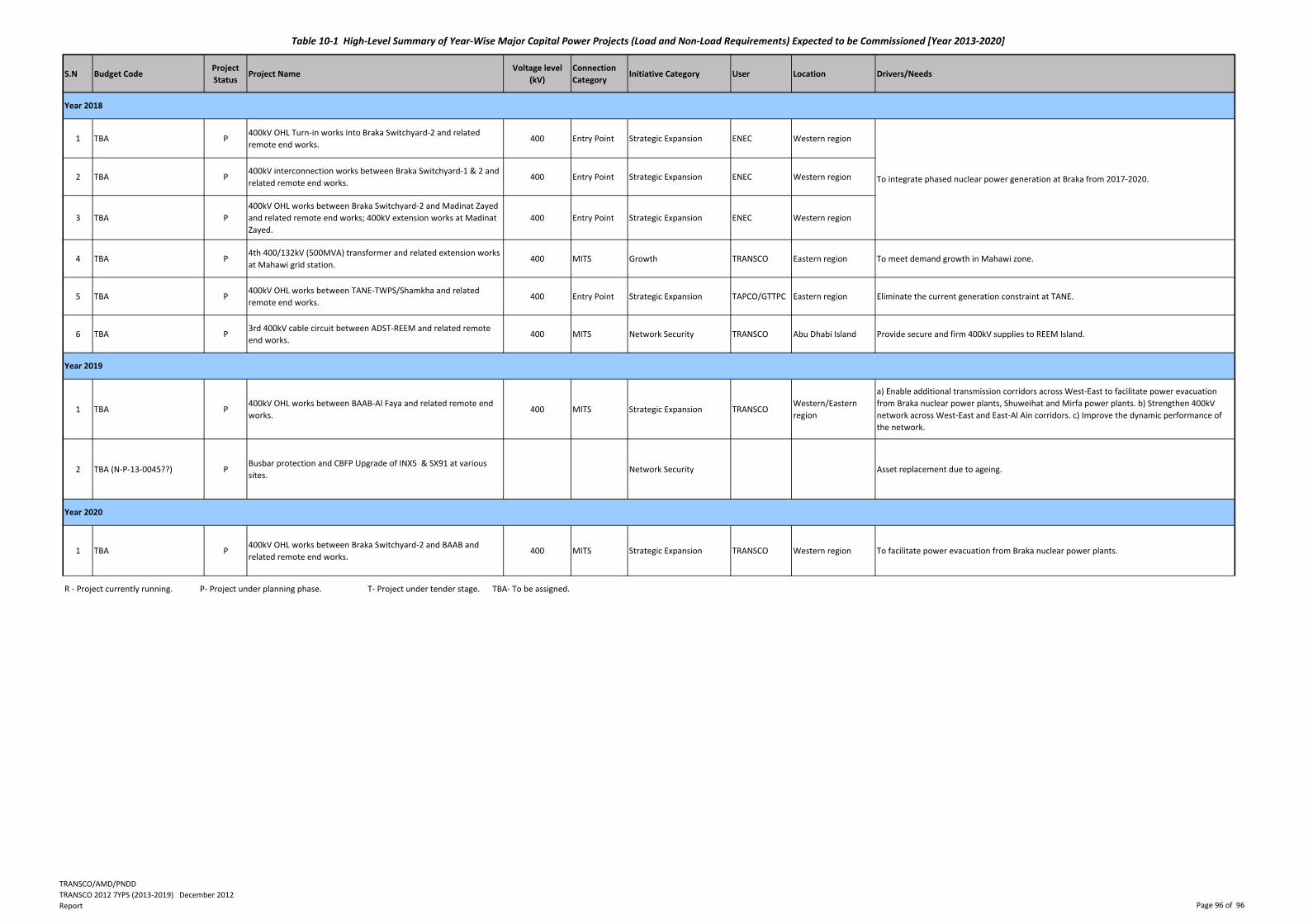
S.N Budget CodeProject
StatusProject Name
Voltage level
(kV)
Connection
CategoryInitiative Category User Location Drivers/Needs
Table 10‐1 High‐Level Summary of Year‐Wise Major Capital Power Projects (Load and Non‐Load Requirements) Expected to be Commissioned [Year 2013‐2020]
1 TBA P400kV OHL Turn‐in works into Braka Switchyard‐2 and related
remote end works. 400 Entry Point Strategic Expansion ENEC Western region
2 TBA P400kV interconnection works between Braka Switchyard‐1 & 2 and
related remote end works. 400 Entry Point Strategic Expansion ENEC Western region
3 TBA P
400kV OHL works between Braka Switchyard‐2 and Madinat Zayed
and related remote end works; 400kV extension works at Madinat
Zayed.
400 Entry Point Strategic Expansion ENEC Western region
4 TBA P4th 400/132kV (500MVA) transformer and related extension works
at Mahawi grid station.400 MITS Growth TRANSCO Eastern region To meet demand growth in Mahawi zone.
5 TBA P400kV OHL works between TANE‐TWPS/Shamkha and related
remote end works.400 Entry Point Strategic Expansion TAPCO/GTTPC Eastern region Eliminate the current generation constraint at TANE.
6 TBA P3rd 400kV cable circuit between ADST‐REEM and related remote
end works.400 MITS Network Security TRANSCO Abu Dhabi Island Provide secure and firm 400kV supplies to REEM Island.
1 TBA P400kV OHL works between BAAB‐Al Faya and related remote end
works.400 MITS Strategic Expansion TRANSCO
Western/Eastern
region
a) Enable additional transmission corridors across West‐East to facilitate power evacuation
from Braka nuclear power plants, Shuweihat and Mirfa power plants. b) Strengthen 400kV
network across West‐East and East‐Al Ain corridors. c) Improve the dynamic performance of
the network.
2 TBA (N‐P‐13‐0045??) PBusbar protection and CBFP Upgrade of INX5 & SX91 at various
sites.Network Security Asset replacement due to ageing.
1 TBA P400kV OHL works between Braka Switchyard‐2 and BAAB and
related remote end works.400 MITS Strategic Expansion TRANSCO Western region To facilitate power evacuation from Braka nuclear power plants.
Year 2020
R ‐ Project currently running. P‐ Project under planning phase. T‐ Project under tender stage. TBA‐ To be assigned.
Year 2018
Year 2019
To integrate phased nuclear power generation at Braka from 2017‐2020.
TRANSCO/AMD/PNDD
TRANSCO 2012 7YPS (2013‐2019) December 2012
Report Page 96 of 96