Embed Size (px)
Citation preview

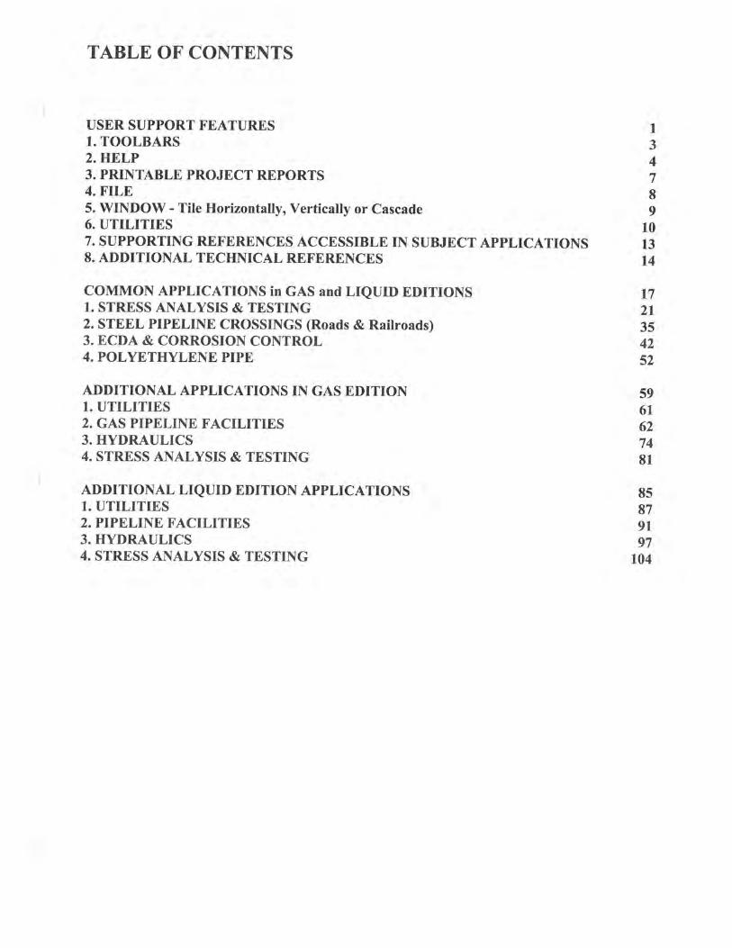
2012 PIPELINE TOOLBOXUSER GUIDE


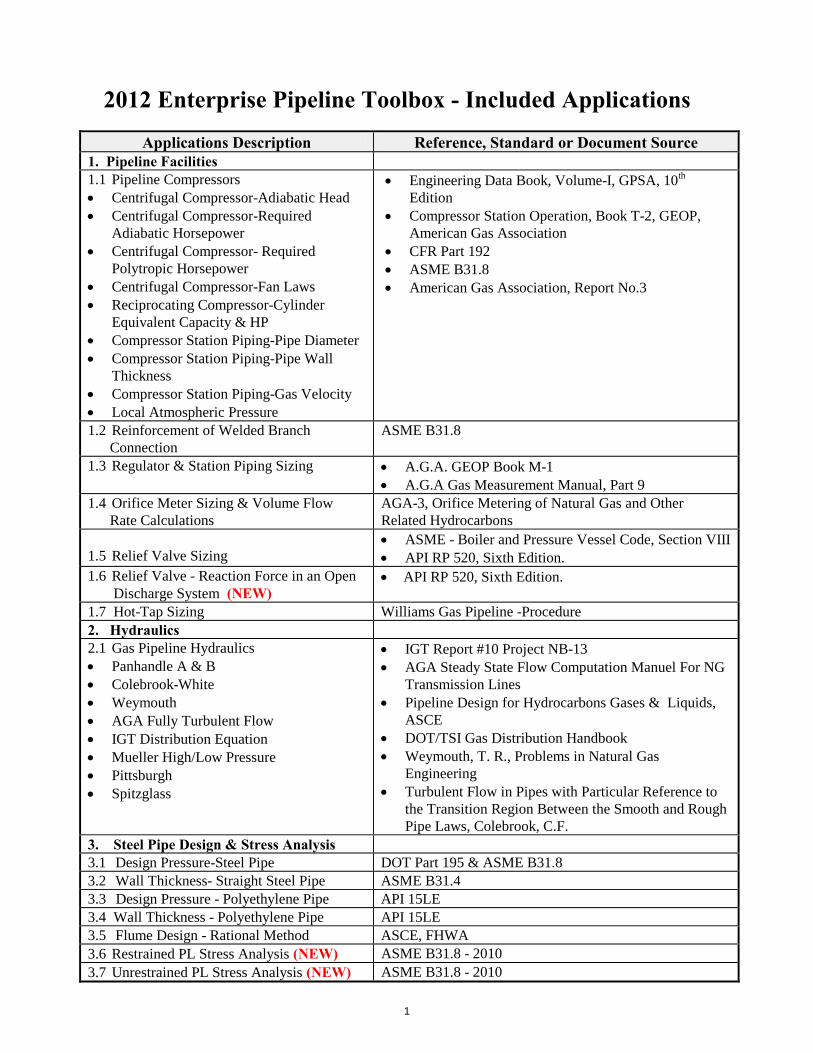
2012 Enterprise Pipeline Toolbox - Included Applications
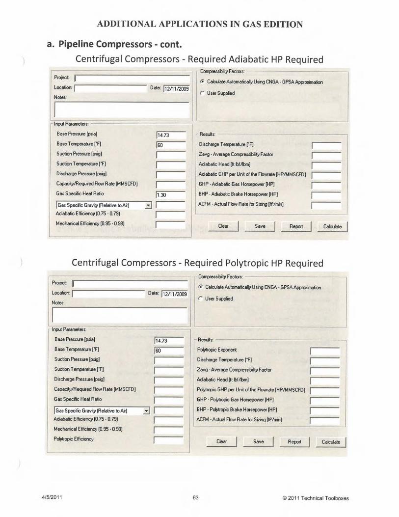
Applications Description Reference, Standard or Document Source1. Pipeline Facilities1.1 Pipeline Compressors Centrifugal Compressor-Adiabatic Head Centrifugal Compressor-Required
Adiabatic Horsepower Centrifugal Compressor- Required
Polytropic Horsepower Centrifugal Compressor-Fan Laws Reciprocating Compressor-Cylinder
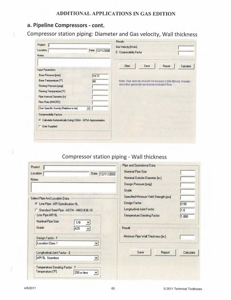
Equivalent Capacity & HP Compressor Station Piping-Pipe Diameter Compressor Station Piping-Pipe Wall
Thickness Compressor Station Piping-Gas Velocity Local Atmospheric Pressure
Engineering Data Book, Volume-I, GPSA, 10th
Edition Compressor Station Operation, Book T-2, GEOP,
American Gas Association CFR Part 192 ASME B31.8 American Gas Association, Report No.3
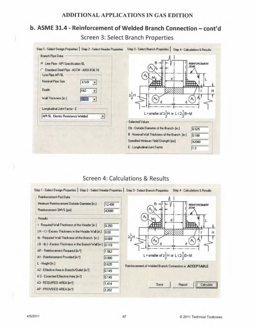
1.2 Reinforcement of Welded BranchConnection
ASME B31.8
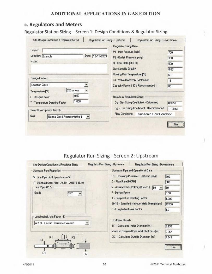
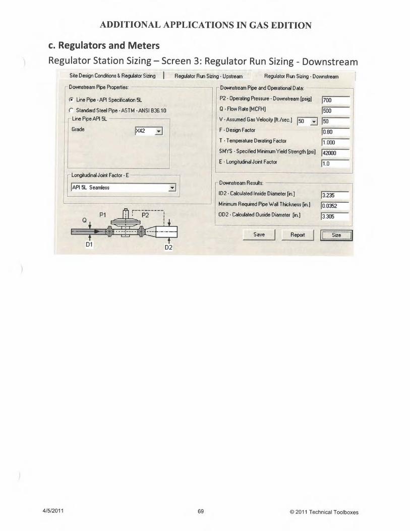
1.3 Regulator & Station Piping Sizing A.G.A. GEOP Book M-1 A.G.A Gas Measurement Manual, Part 9
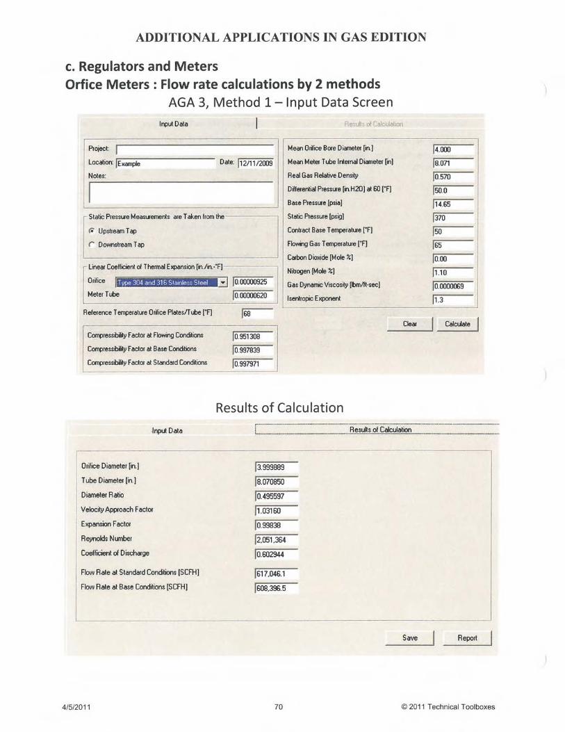
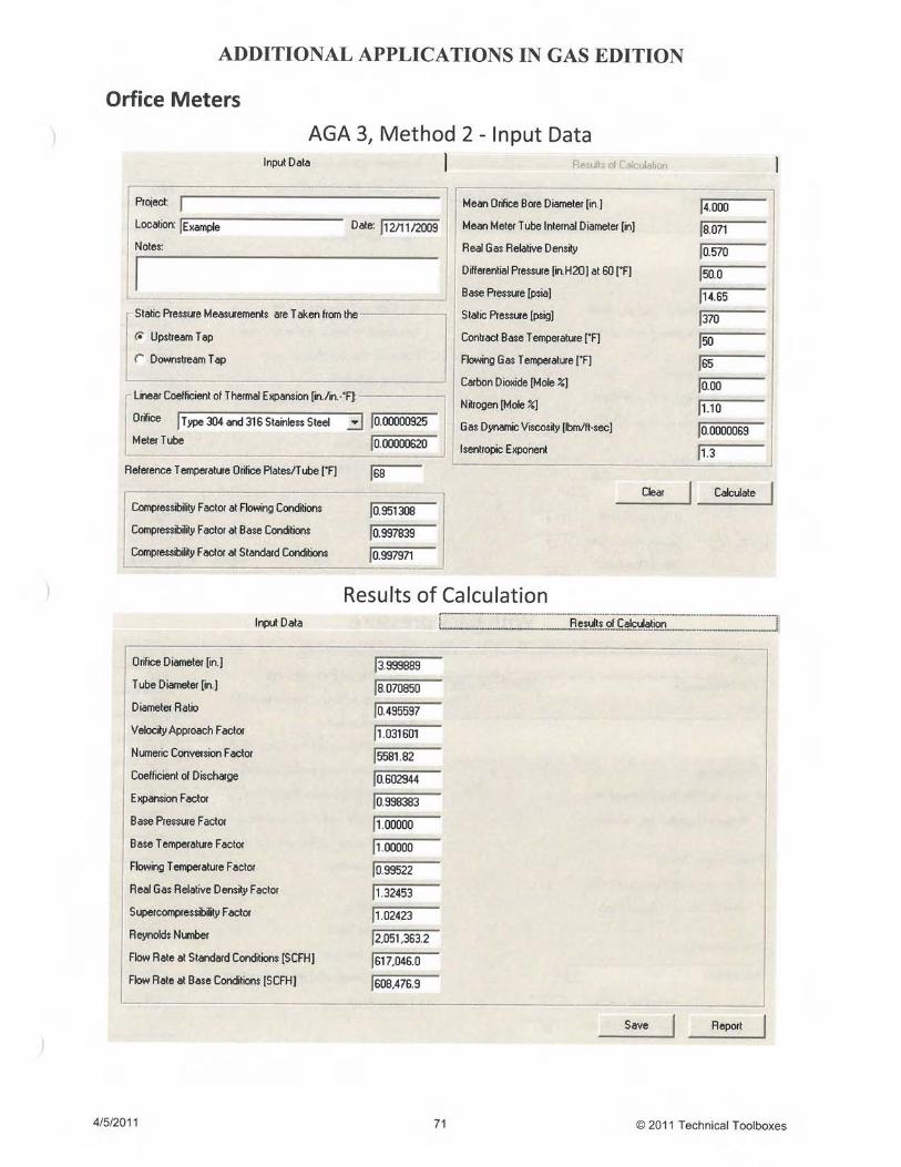
1.4 Orifice Meter Sizing & Volume FlowRate Calculations
AGA-3, Orifice Metering of Natural Gas and OtherRelated Hydrocarbons
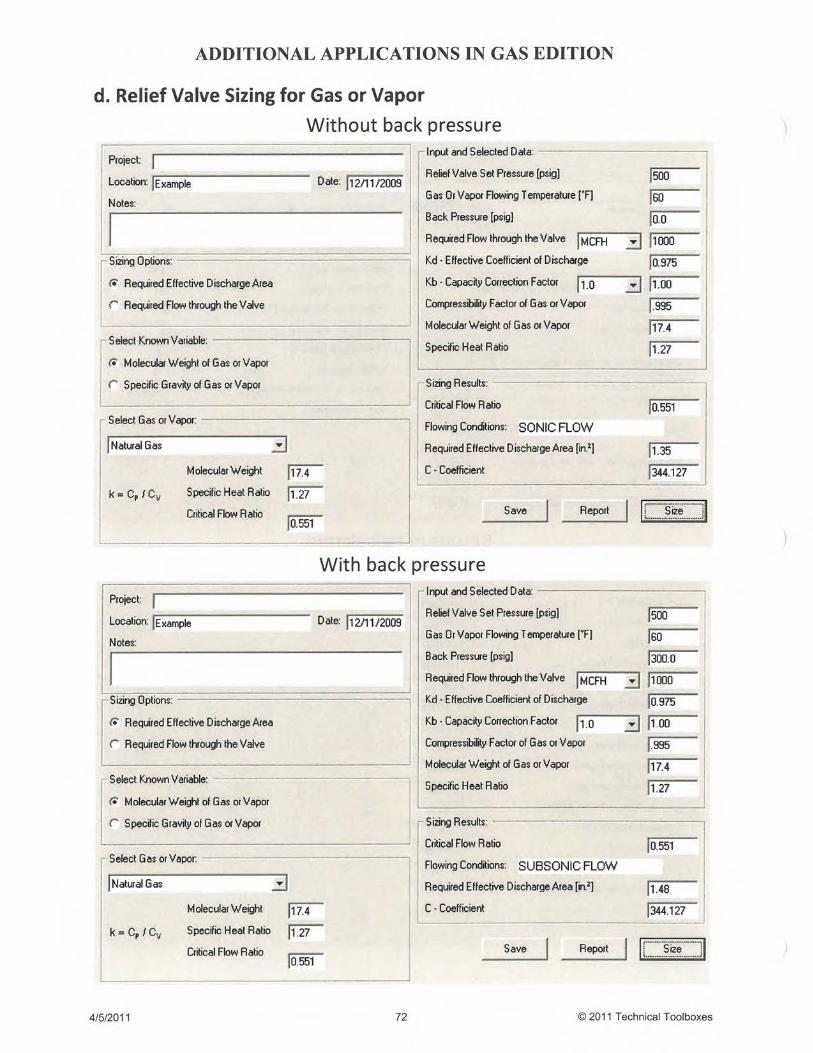
1.5 Relief Valve Sizing ASME - Boiler and Pressure Vessel Code, Section VIII API RP 520, Sixth Edition.
1.6 Relief Valve - Reaction Force in an OpenDischarge System (NEW)
API RP 520, Sixth Edition.
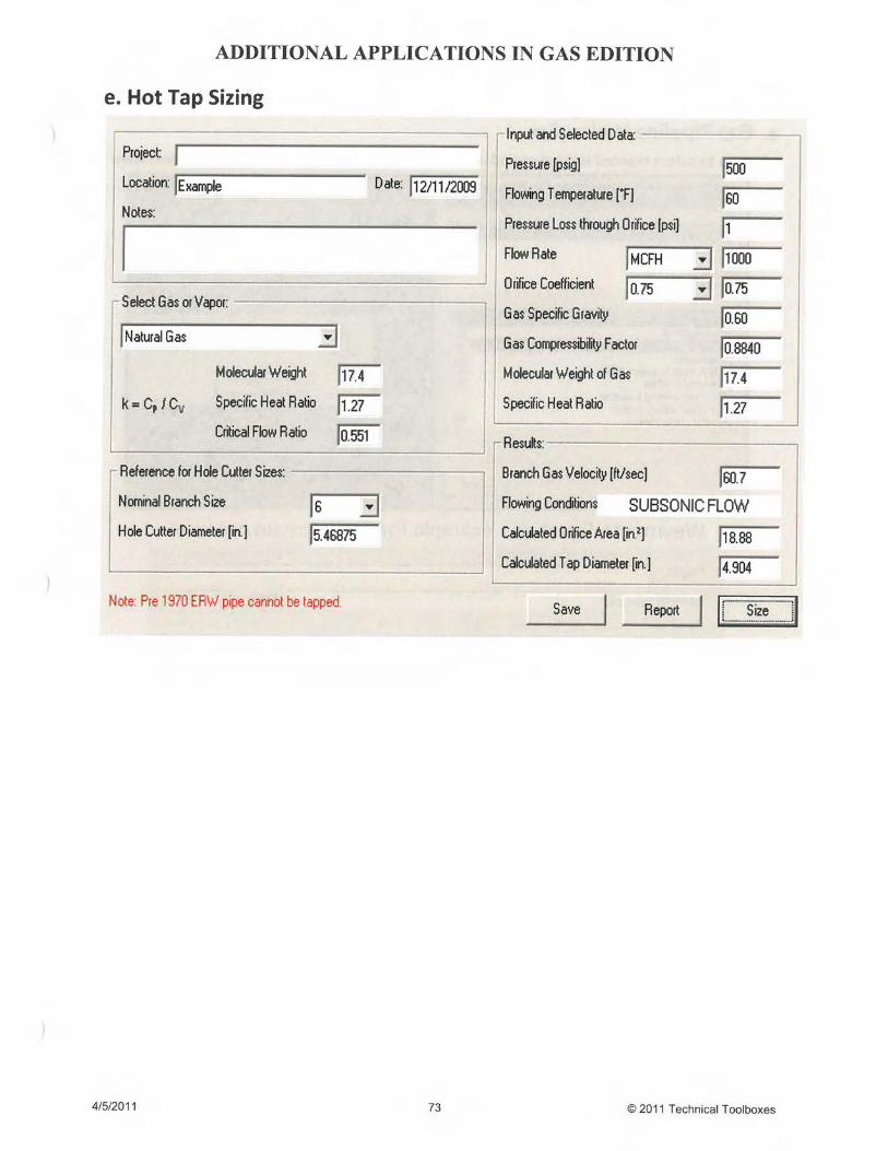
1.7 Hot-Tap Sizing Williams Gas Pipeline -Procedure
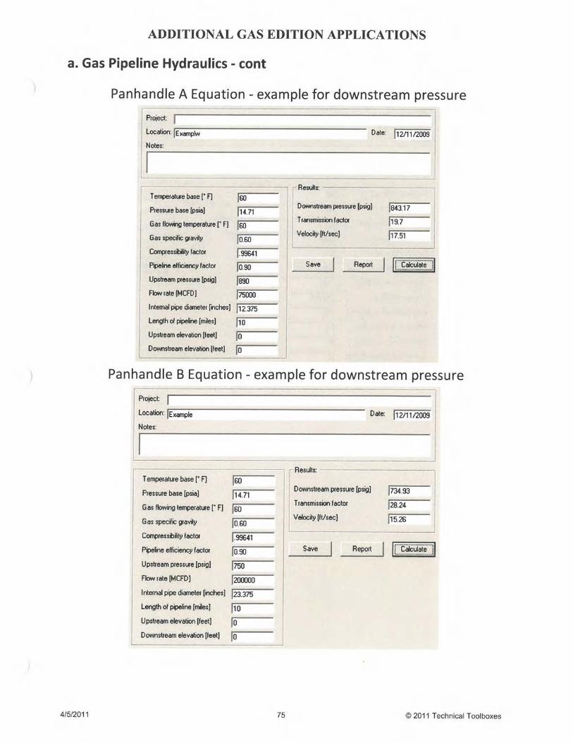
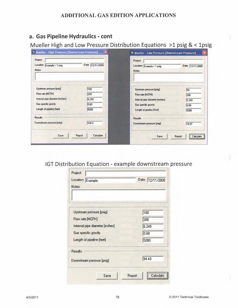
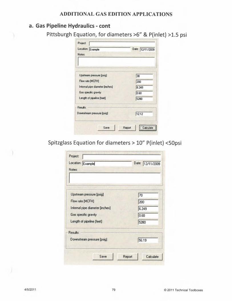
2. Hydraulics2.1 Gas Pipeline Hydraulics Panhandle A & B Colebrook-White Weymouth AGA Fully Turbulent Flow IGT Distribution Equation Mueller High/Low Pressure Pittsburgh Spitzglass
IGT Report #10 Project NB-13 AGA Steady State Flow Computation Manuel For NG
Transmission Lines Pipeline Design for Hydrocarbons Gases & Liquids,
ASCE DOT/TSI Gas Distribution Handbook Weymouth, T. R., Problems in Natural Gas
Engineering Turbulent Flow in Pipes with Particular Reference to
the Transition Region Between the Smooth and RoughPipe Laws, Colebrook, C.F.
3. Steel Pipe Design & Stress Analysis3.1 Design Pressure-Steel Pipe DOT Part 195 & ASME B31.83.2 Wall Thickness- Straight Steel Pipe ASME B31.43.3 Design Pressure - Polyethylene Pipe API 15LE3.4 Wall Thickness - Polyethylene Pipe API 15LE3.5 Flume Design - Rational Method ASCE, FHWA
3.6 Restrained PL Stress Analysis (NEW) ASME B31.8 - 2010
3.7 Unrestrained PL Stress Analysis (NEW) ASME B31.8 - 2010
1
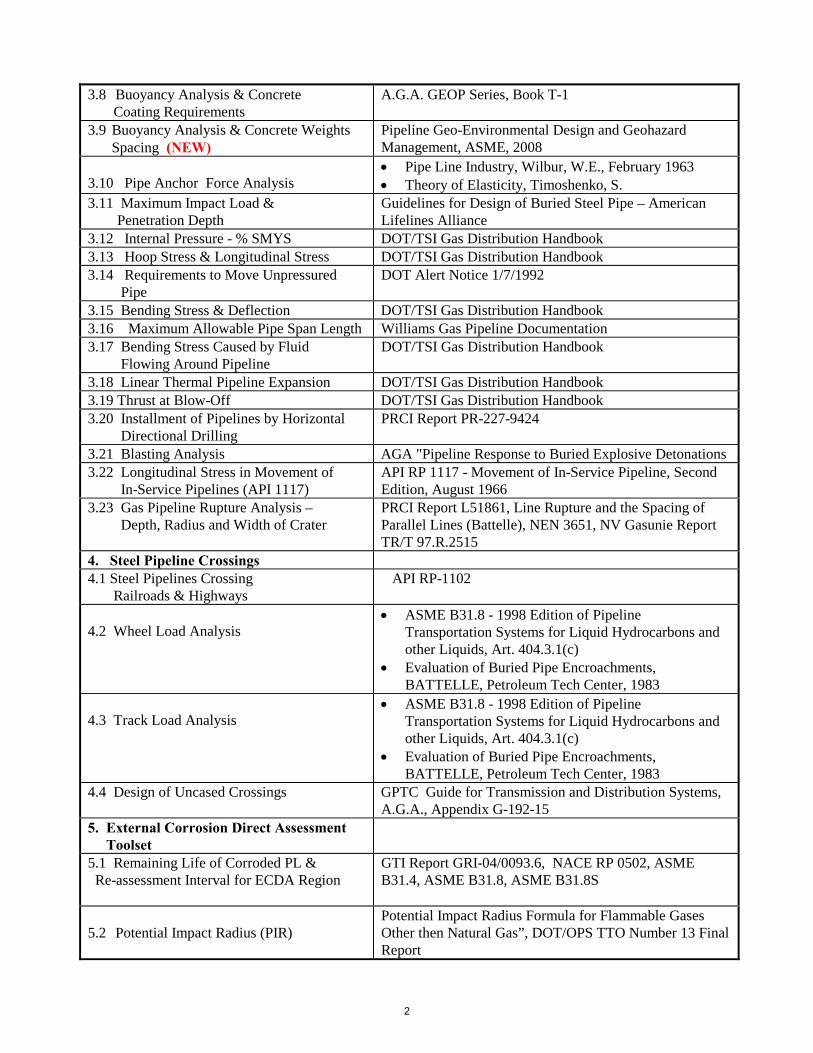
3.8 Buoyancy Analysis & ConcreteCoating Requirements
A.G.A. GEOP Series, Book T-1
3.9 Buoyancy Analysis & Concrete WeightsSpacing (NEW)
Pipeline Geo-Environmental Design and GeohazardManagement, ASME, 2008
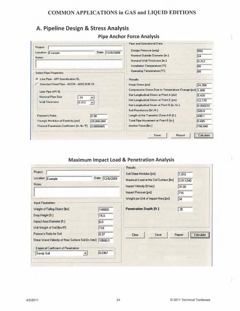
3.10 Pipe Anchor Force Analysis Pipe Line Industry, Wilbur, W.E., February 1963 Theory of Elasticity, Timoshenko, S.
3.11 Maximum Impact Load &Penetration Depth
Guidelines for Design of Buried Steel Pipe – AmericanLifelines Alliance
3.12 Internal Pressure - % SMYS DOT/TSI Gas Distribution Handbook3.13 Hoop Stress & Longitudinal Stress DOT/TSI Gas Distribution Handbook3.14 Requirements to Move Unpressured
PipeDOT Alert Notice 1/7/1992
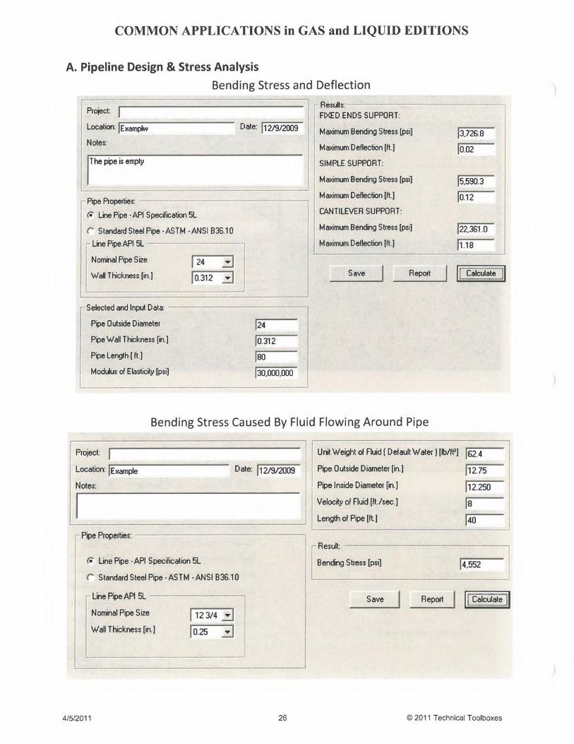
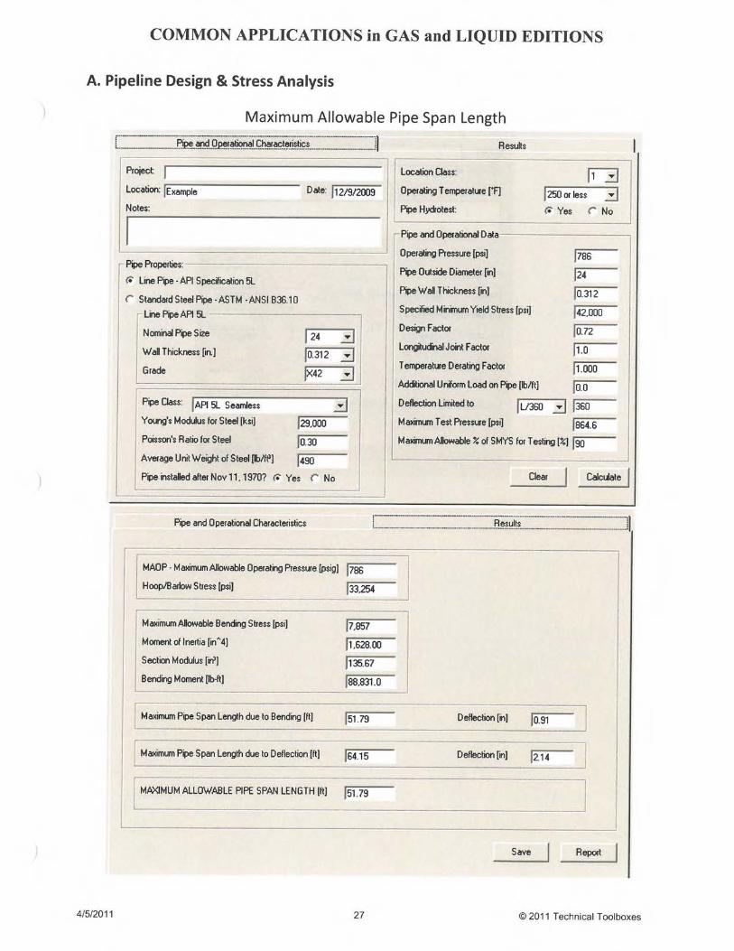
3.15 Bending Stress & Deflection DOT/TSI Gas Distribution Handbook3.16 Maximum Allowable Pipe Span Length Williams Gas Pipeline Documentation3.17 Bending Stress Caused by Fluid
Flowing Around PipelineDOT/TSI Gas Distribution Handbook
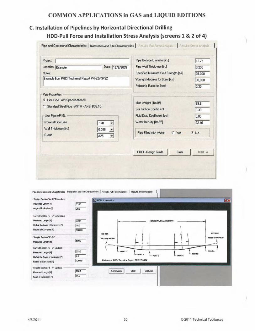
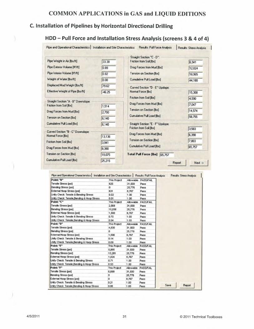
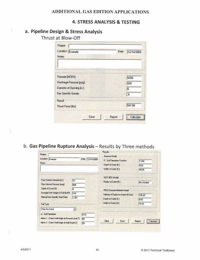
3.18 Linear Thermal Pipeline Expansion DOT/TSI Gas Distribution Handbook3.19 Thrust at Blow-Off DOT/TSI Gas Distribution Handbook3.20 Installment of Pipelines by Horizontal
Directional DrillingPRCI Report PR-227-9424
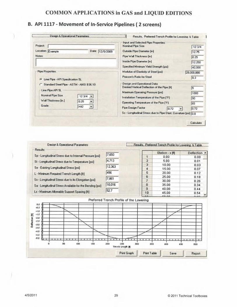
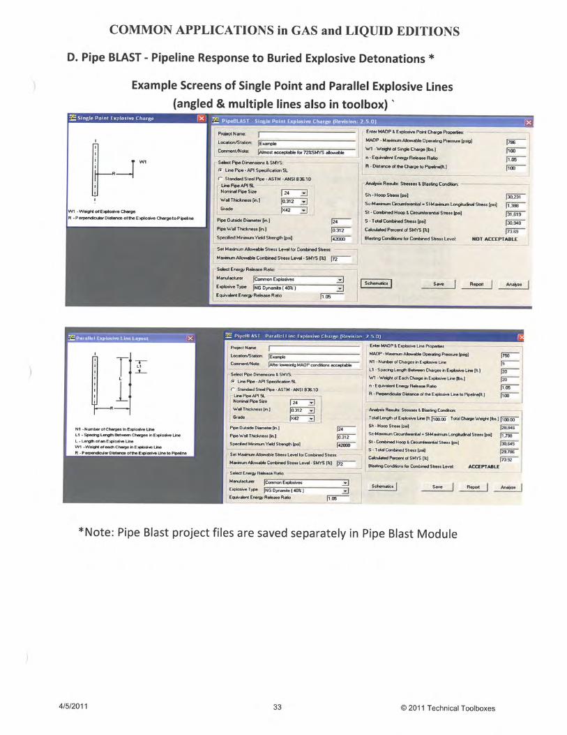
3.21 Blasting Analysis AGA "Pipeline Response to Buried Explosive Detonations3.22 Longitudinal Stress in Movement of
In-Service Pipelines (API 1117)API RP 1117 - Movement of In-Service Pipeline, SecondEdition, August 1966
3.23 Gas Pipeline Rupture Analysis –Depth, Radius and Width of Crater
PRCI Report L51861, Line Rupture and the Spacing ofParallel Lines (Battelle), NEN 3651, NV Gasunie ReportTR/T 97.R.2515
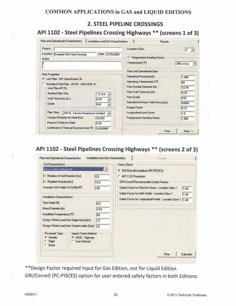
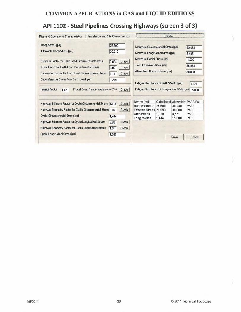
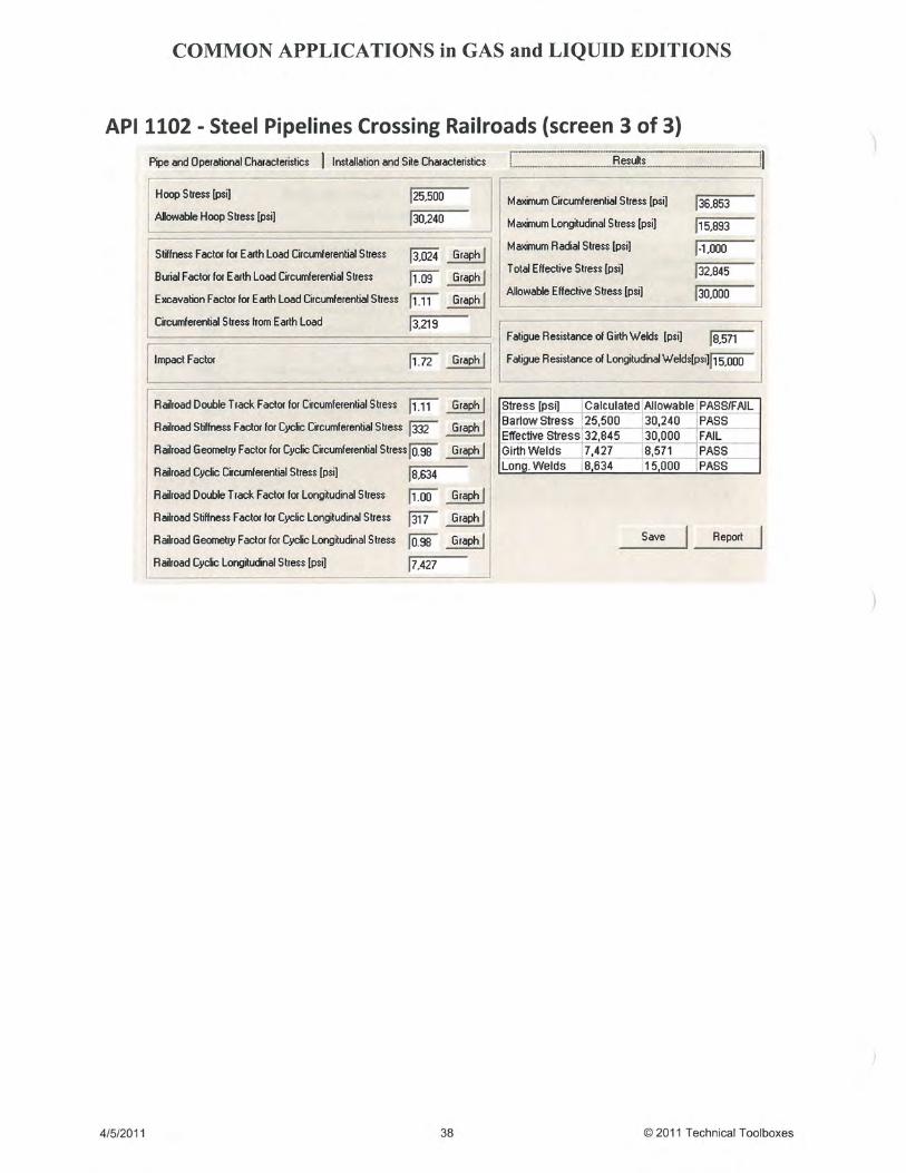
4. Steel Pipeline Crossings4.1 Steel Pipelines Crossing
Railroads & HighwaysAPI RP-1102
4.2 Wheel Load Analysis ASME B31.8 - 1998 Edition of Pipeline
Transportation Systems for Liquid Hydrocarbons andother Liquids, Art. 404.3.1(c)
Evaluation of Buried Pipe Encroachments,BATTELLE, Petroleum Tech Center, 1983
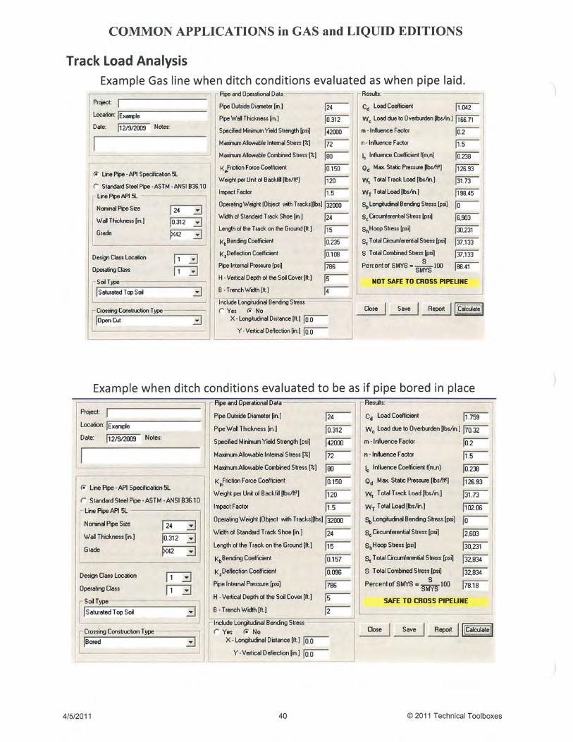
4.3 Track Load Analysis ASME B31.8 - 1998 Edition of Pipeline
Transportation Systems for Liquid Hydrocarbons andother Liquids, Art. 404.3.1(c)
Evaluation of Buried Pipe Encroachments,BATTELLE, Petroleum Tech Center, 1983
4.4 Design of Uncased Crossings GPTC Guide for Transmission and Distribution Systems,A.G.A., Appendix G-192-15
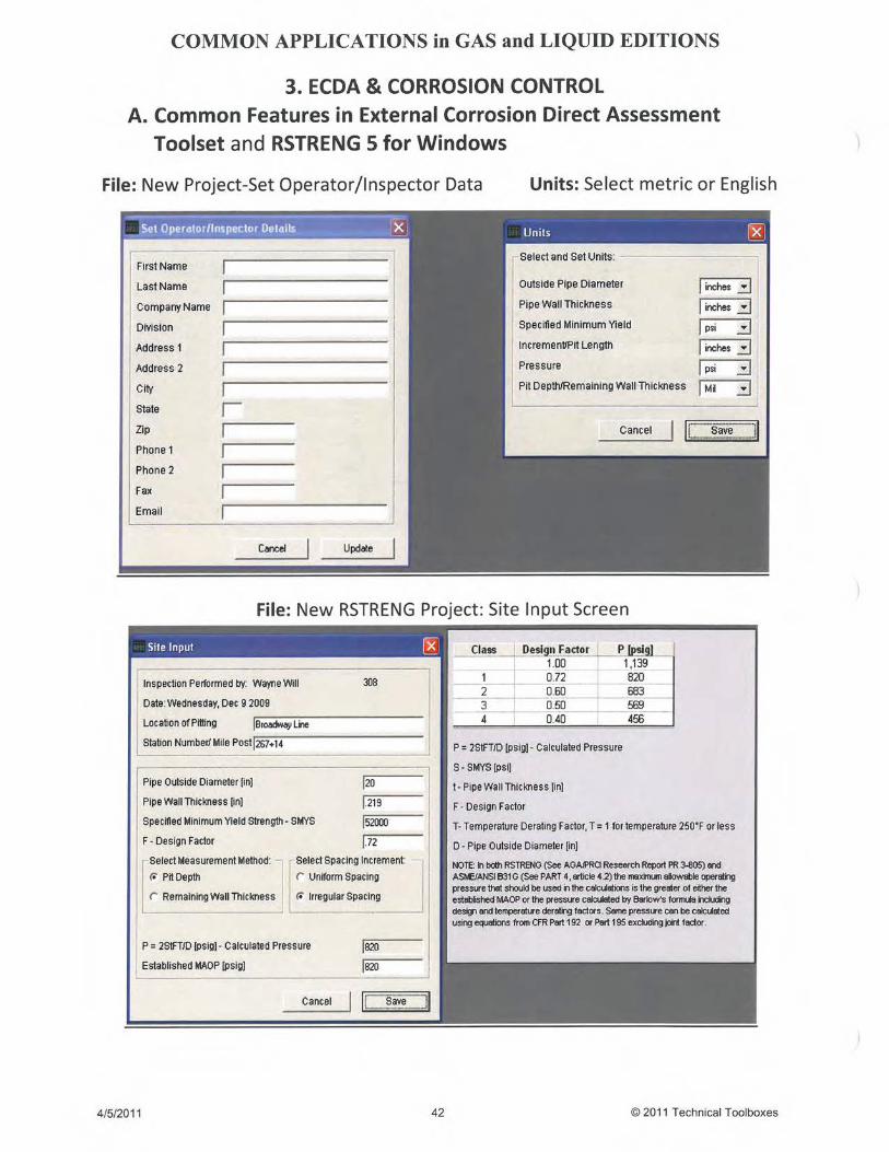
5. External Corrosion Direct AssessmentToolset
5.1 Remaining Life of Corroded PL &Re-assessment Interval for ECDA Region
GTI Report GRI-04/0093.6, NACE RP 0502, ASMEB31.4, ASME B31.8, ASME B31.8S
5.2 Potential Impact Radius (PIR)Potential Impact Radius Formula for Flammable GasesOther then Natural Gas”, DOT/OPS TTO Number 13 FinalReport
2
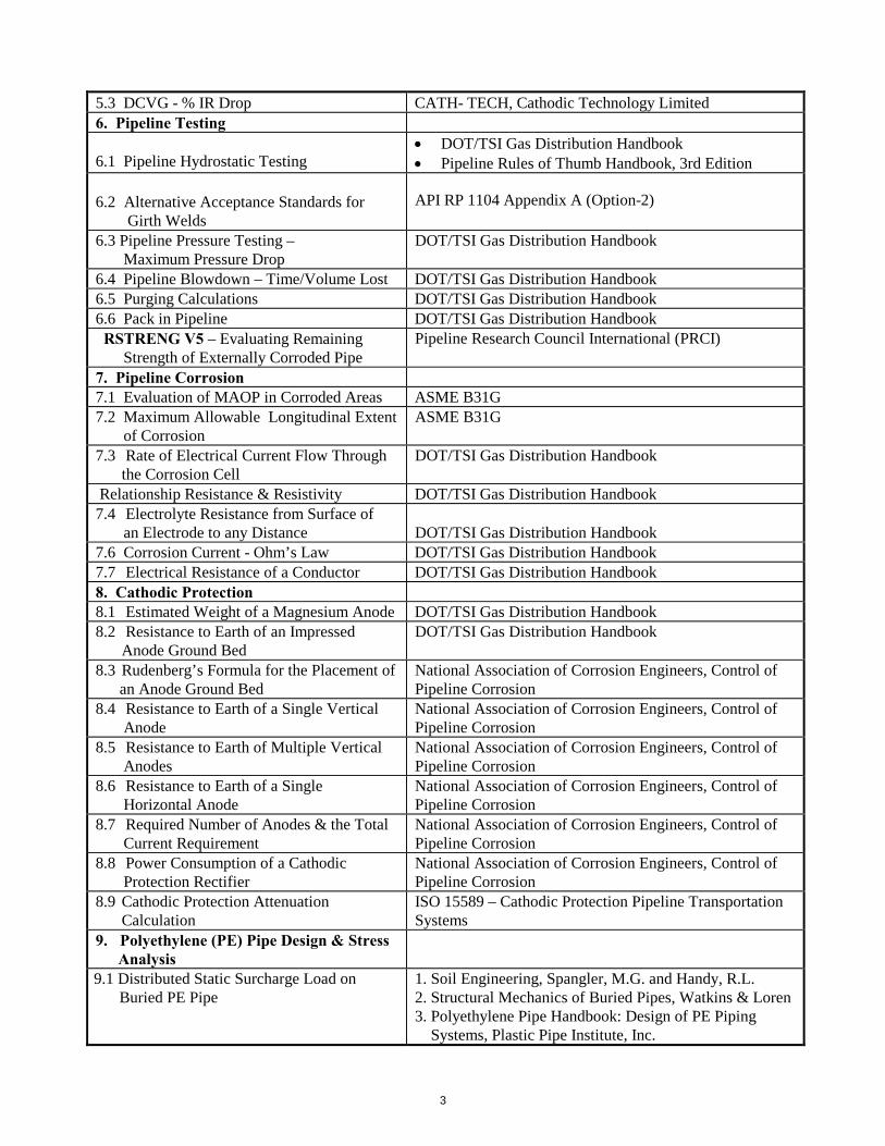
5.3 DCVG - % IR Drop CATH- TECH, Cathodic Technology Limited
6. Pipeline Testing
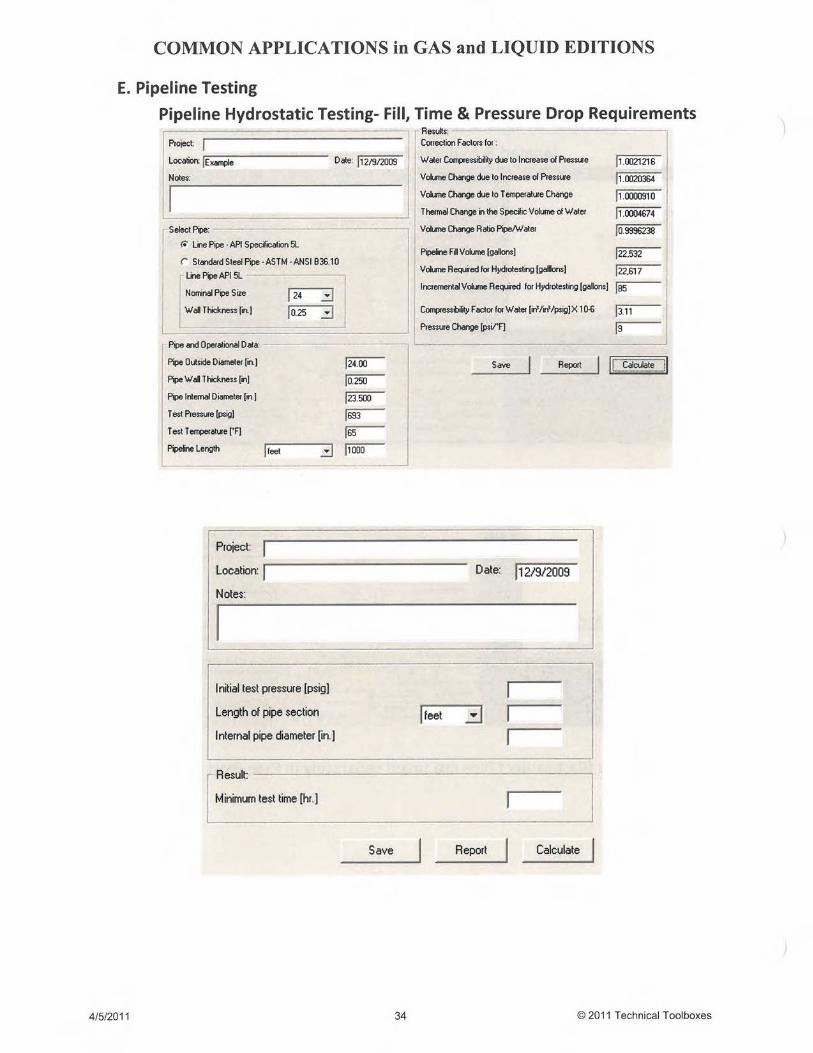
6.1 Pipeline Hydrostatic Testing DOT/TSI Gas Distribution Handbook Pipeline Rules of Thumb Handbook, 3rd Edition
6.2 Alternative Acceptance Standards forGirth Welds
API RP 1104 Appendix A (Option-2)
6.3 Pipeline Pressure Testing –Maximum Pressure Drop
DOT/TSI Gas Distribution Handbook
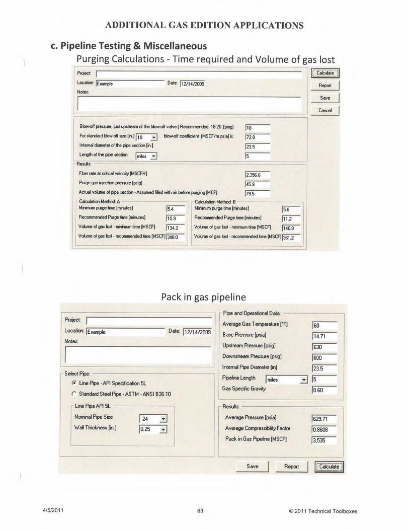
6.4 Pipeline Blowdown – Time/Volume Lost DOT/TSI Gas Distribution Handbook6.5 Purging Calculations DOT/TSI Gas Distribution Handbook6.6 Pack in Pipeline DOT/TSI Gas Distribution Handbook
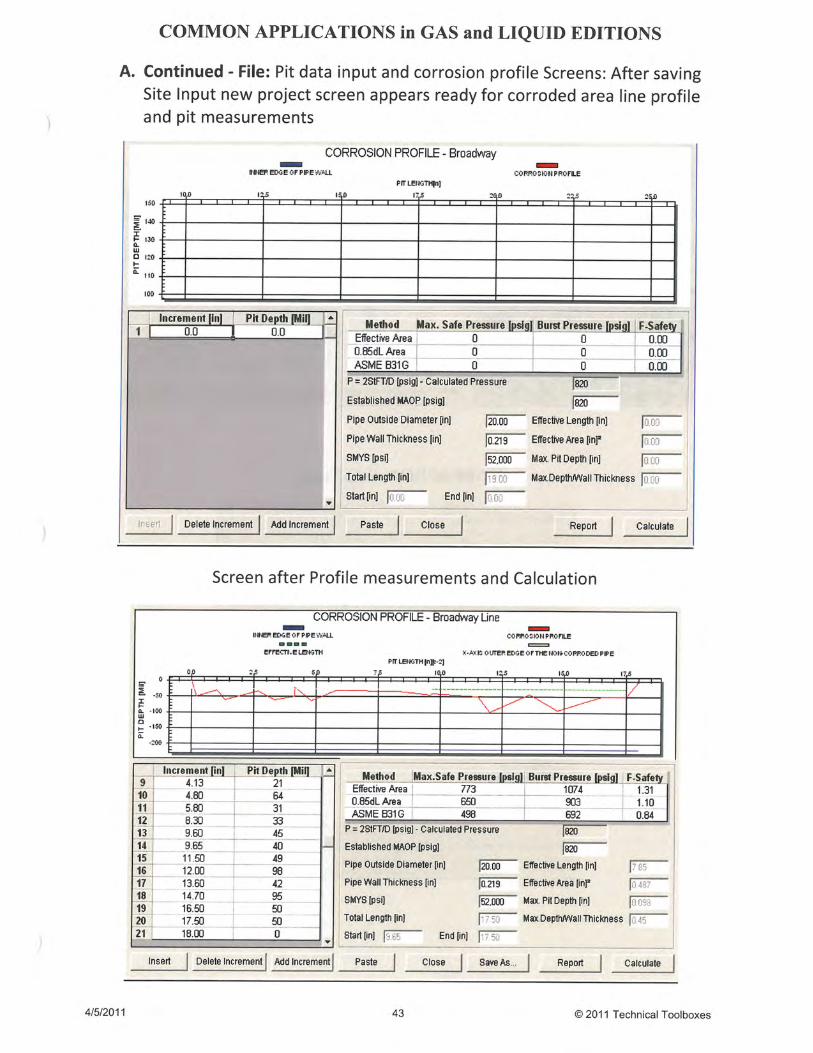
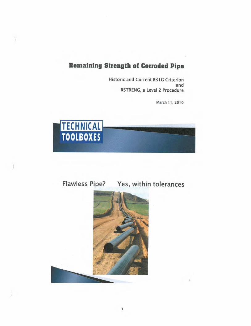
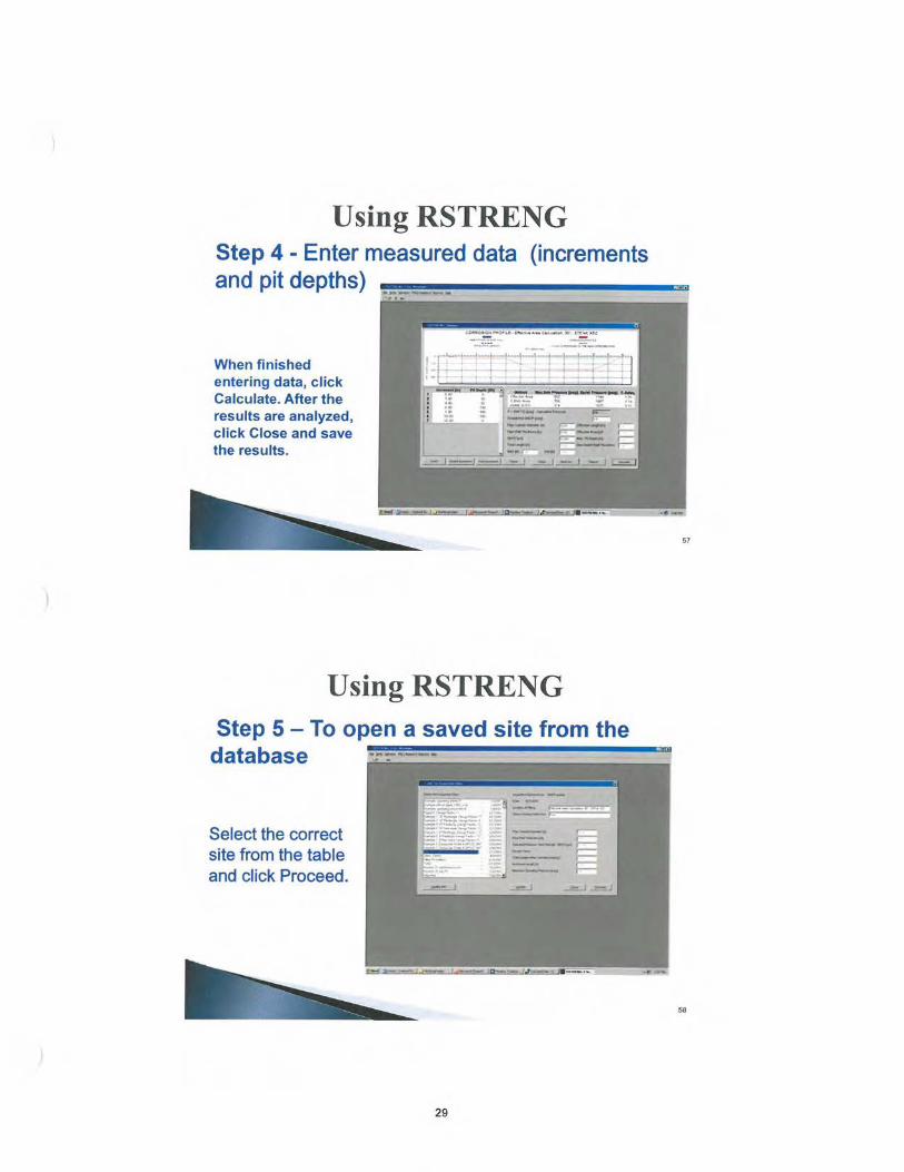
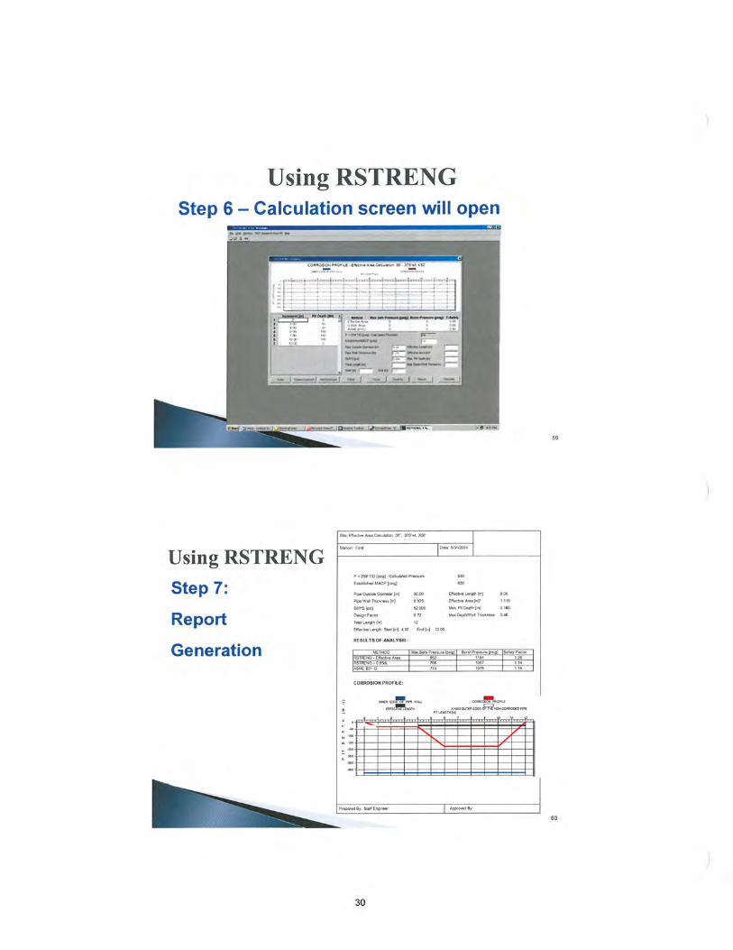
RSTRENG V5 – Evaluating RemainingStrength of Externally Corroded Pipe
Pipeline Research Council International (PRCI)
7. Pipeline Corrosion7.1 Evaluation of MAOP in Corroded Areas ASME B31G7.2 Maximum Allowable Longitudinal Extent
of CorrosionASME B31G
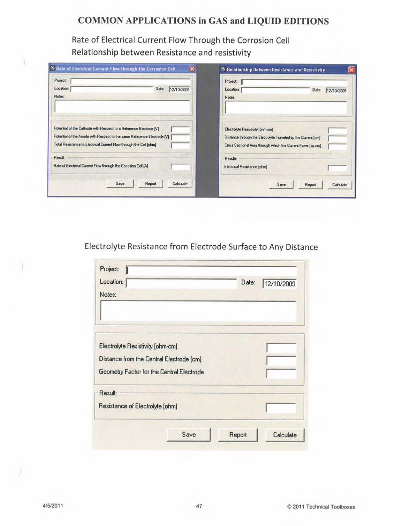
7.3 Rate of Electrical Current Flow Throughthe Corrosion Cell
DOT/TSI Gas Distribution Handbook
Relationship Resistance & Resistivity DOT/TSI Gas Distribution Handbook7.4 Electrolyte Resistance from Surface of
an Electrode to any Distance DOT/TSI Gas Distribution Handbook7.6 Corrosion Current - Ohm’s Law DOT/TSI Gas Distribution Handbook7.7 Electrical Resistance of a Conductor DOT/TSI Gas Distribution Handbook
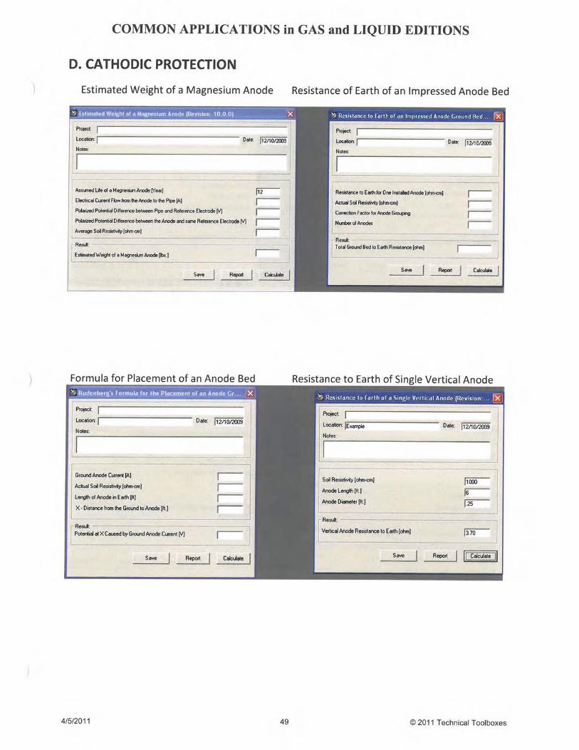
8. Cathodic Protection8.1 Estimated Weight of a Magnesium Anode DOT/TSI Gas Distribution Handbook8.2 Resistance to Earth of an Impressed
Anode Ground BedDOT/TSI Gas Distribution Handbook
8.3 Rudenberg’s Formula for the Placement ofan Anode Ground Bed
National Association of Corrosion Engineers, Control ofPipeline Corrosion
8.4 Resistance to Earth of a Single VerticalAnode
National Association of Corrosion Engineers, Control ofPipeline Corrosion
8.5 Resistance to Earth of Multiple VerticalAnodes
National Association of Corrosion Engineers, Control ofPipeline Corrosion
8.6 Resistance to Earth of a SingleHorizontal Anode
National Association of Corrosion Engineers, Control ofPipeline Corrosion
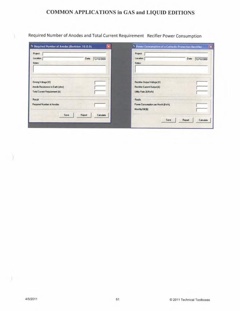
8.7 Required Number of Anodes & the TotalCurrent Requirement
National Association of Corrosion Engineers, Control ofPipeline Corrosion
8.8 Power Consumption of a CathodicProtection Rectifier
National Association of Corrosion Engineers, Control ofPipeline Corrosion
8.9 Cathodic Protection AttenuationCalculation
ISO 15589 – Cathodic Protection Pipeline TransportationSystems
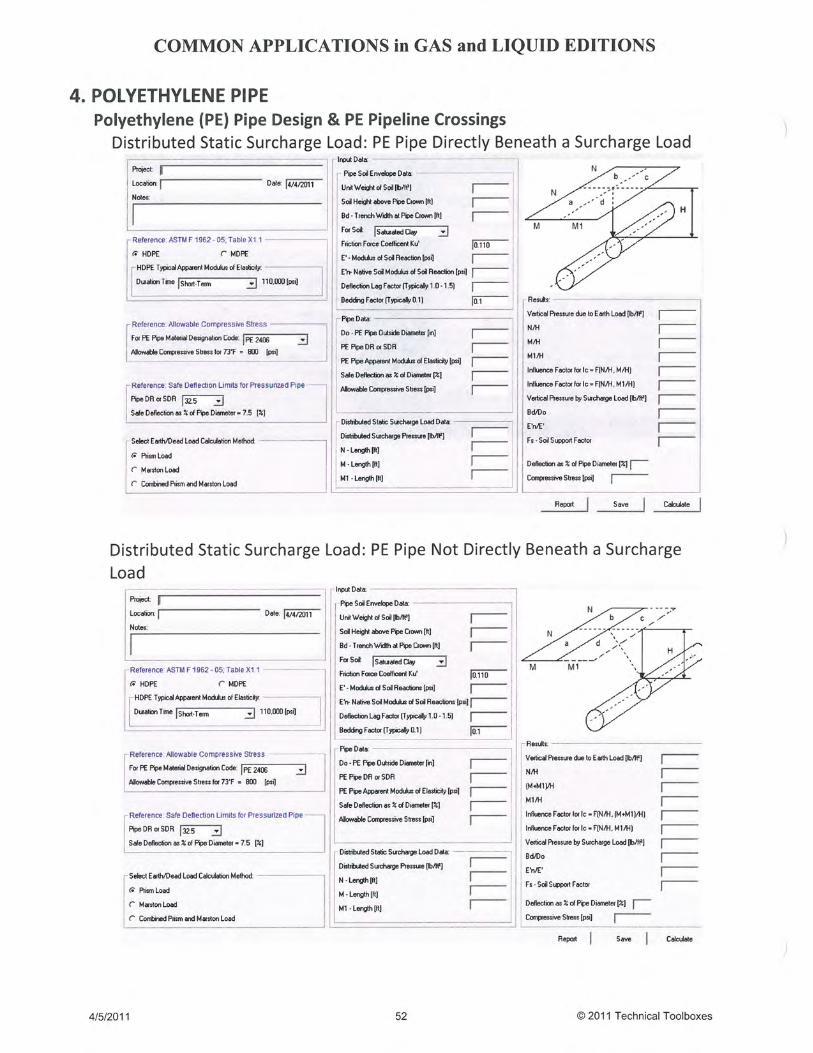
9. Polyethylene (PE) Pipe Design & StressAnalysis
9.1 Distributed Static Surcharge Load onBuried PE Pipe
1. Soil Engineering, Spangler, M.G. and Handy, R.L.2. Structural Mechanics of Buried Pipes, Watkins & Loren3. Polyethylene Pipe Handbook: Design of PE Piping
Systems, Plastic Pipe Institute, Inc.
3

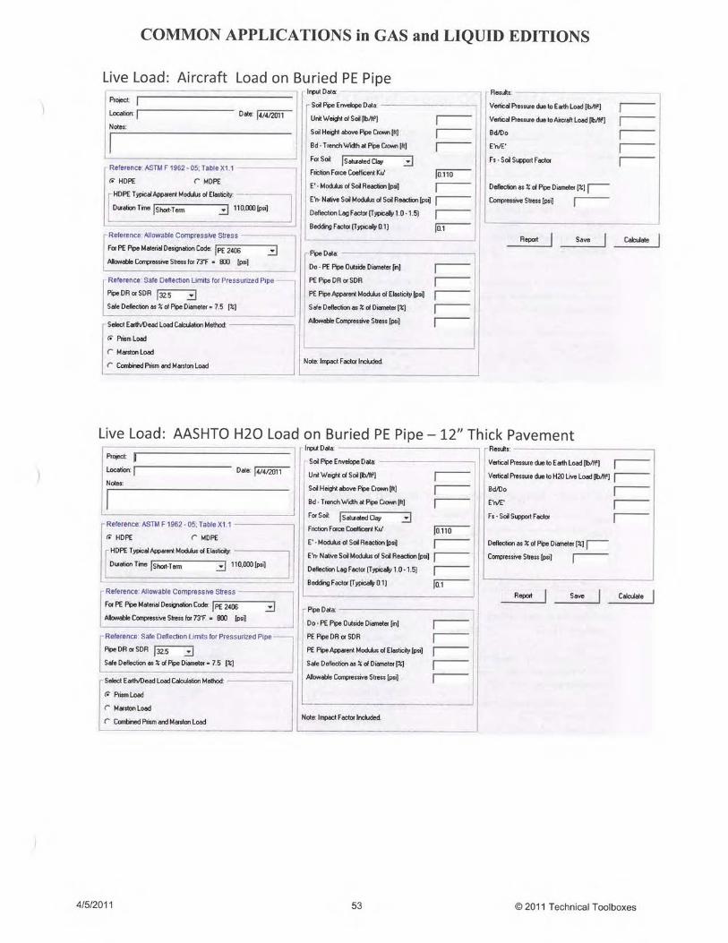
9.2 Surcharge Live Load on Buried PE Pipe & Pipeline Crossings9.2.1 Aircraft Load on Buried PE Pipe 1. Soil Engineering, Spangler, M.G. and Handy, R.L.
2. Structural Mechanics of Buried Pipes, Watkins, R.K,and Loren, R, A,
3. Polyethylene Pipe Handbook: Design of PE PipingSystems, Plastic Pipe Institute, Inc.
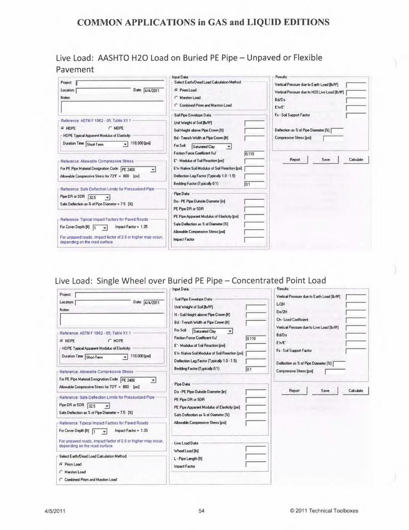
9.2.2 AASHTO Std. H20 Vehicular Loadingfor Paved & Flexible/Unpaved Surfaces
9.2.3 Off Road Crossing-Concentrated PointLoad Single Wheel
9.2.4 Off Road Crossing-Concentrated PointLoad Multiple Wheel
9.2.5 Off Road Crossing- Concentrated PointLoad Not over Buried PE Pipe
9.2.6 Off Road Crossing-Unpaved Road Only(Timoshenko Equation)
9.2.7 Cooper E-80 Railroad Load on BuriedPE Pipe
1. Soil Engineering, Spangler, .G. and Handy, R.L.2. Structural Mechanics of Buried Pipes, Watkins, R.K,
and Loren, R, A,3. Polyethylene Pipe Handbook: Design of PE Piping
Systems, Plastic Pipe Institute, Inc.4. Modulus of Soil Reaction for Buried Flexible Pipe,
ASCE Geotechnical Journal Vol. 103, Howard, A.K.5. Evaluation of Modulus of Soil Reaction E’ and Its
Variation with Depth, Report No.UCB/GT/82-02,Duncan,JM/Hartley,JD, Univ. of Calif, Berkeley
9.3 Installation of Polyethylene Pipelinesby Horizontal Directional Drilling(HDD)
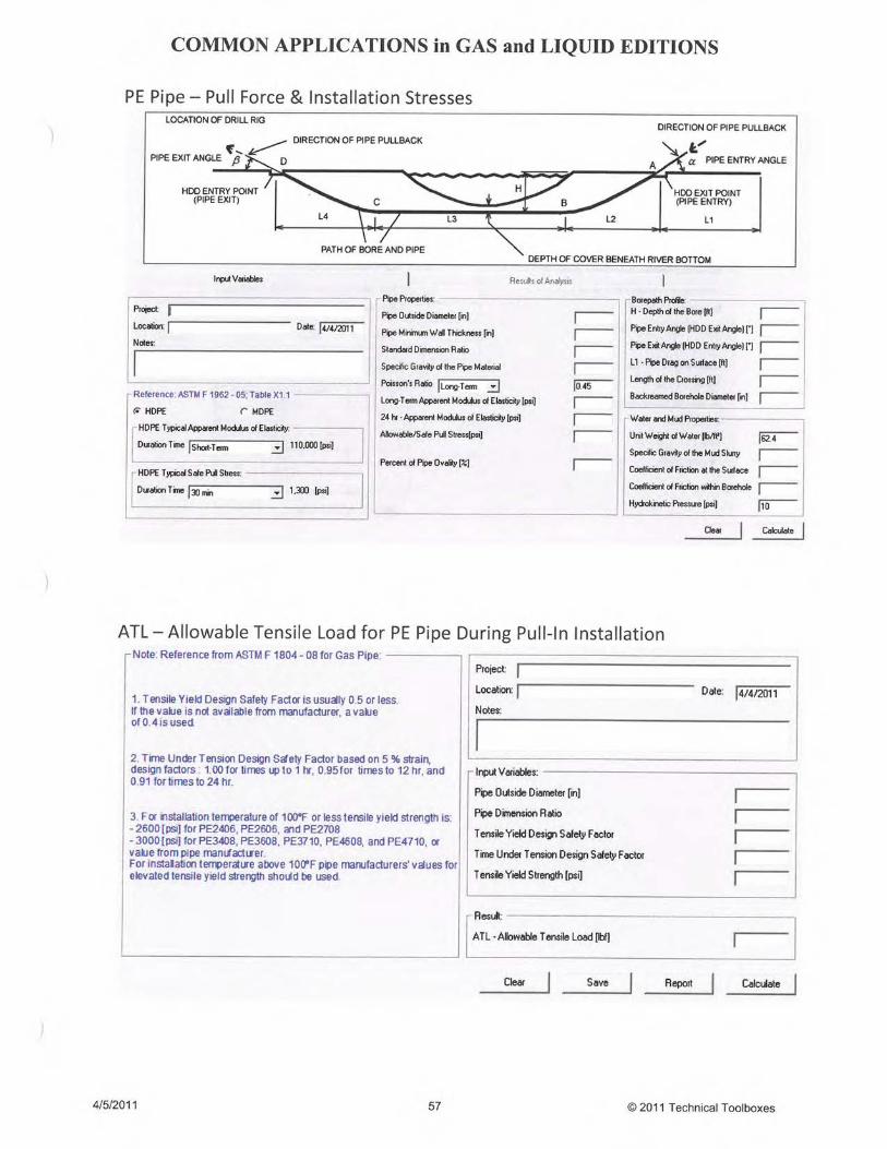
9.3.1 PE Pipe – Pull Force & InstallationStress Analysis
ASTM F 1962 05
9.3.2 HDD PE Pipe - ATL Allowable TensileLoad During Pull-In Installation
ASTM F 1962 - 05 and ASTM F 1804 - 08
9.3.3 PE Pipe - Post-Installation StressAnalysis
ASTM F 1962 - 05
10. Data Bases10.1 Physical Properties of Fluids British Gas - GasVLE10.2 Pipe Databases for Steel,
Polyethylene & Custom Pipe Spec. for Line Pipe, API 5L Std Steel Pipe, ASTM B36.10
Spec. for Polyethylene Line Pipe, API 15LE
11. Gas Properties Calculations11.1 Gas Mixture Properties AGA-8 & API MPMS Chapter 14.511.2 Local Atmospheric Pressure AGA Part 3
12. Utilities12.1 Gas Mixture Properties GPA Standard 2172, AGA Report No. 8,API MPMS 14.212.2 Physical Properties of Fluids Various12.3 Document Management Module Application developed by TTI12.4 Applications Integration Module Application developed by TTI
12.5 Units Conversion Module International System of Units (SI) ASTM Metric Guide E380-72E
ANSI Standard Z201.1
13. Standards/Regulations/Forms13.1 Pipeline Safety Laws US Department of Transportation13.2 DOT Regulations US Department of Transportation 49 CFR - Parts 190-19513.3 DOT Forms & Instructions for
ReportingUS Department of Transportation49 CFR - Parts 190-195
13.4 Canadian Pipeline Standards Internet link provided to CSA website.
4
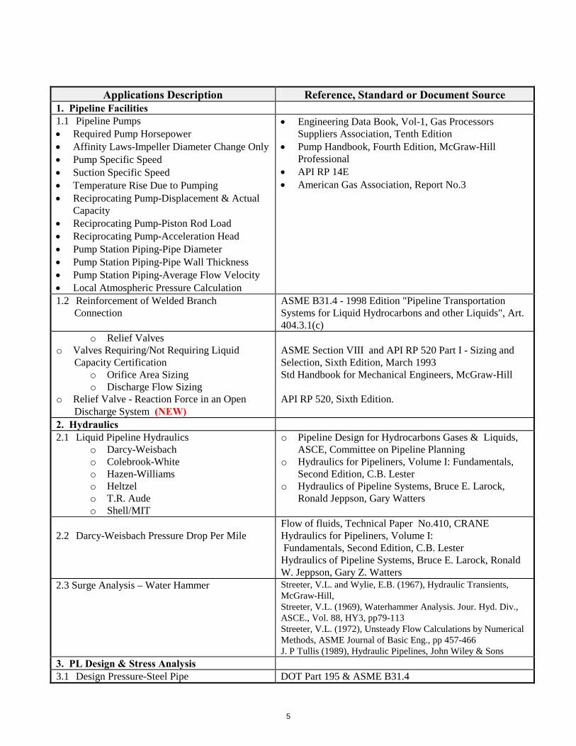
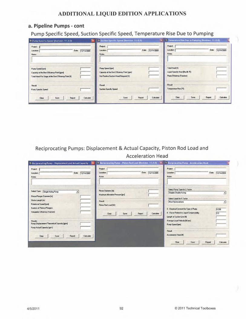
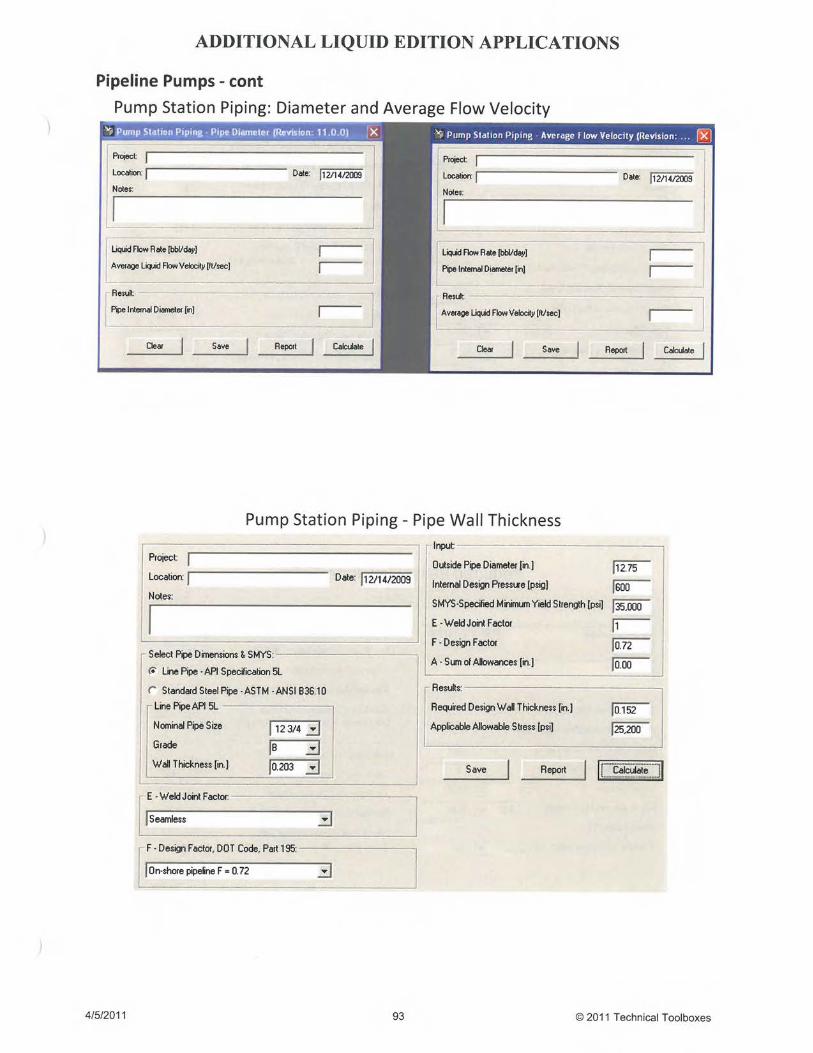
Applications Description Reference, Standard or Document Source1. Pipeline Facilities1.1 Pipeline Pumps Required Pump Horsepower Affinity Laws-Impeller Diameter Change Only Pump Specific Speed Suction Specific Speed Temperature Rise Due to Pumping Reciprocating Pump-Displacement & Actual
Capacity Reciprocating Pump-Piston Rod Load Reciprocating Pump-Acceleration Head Pump Station Piping-Pipe Diameter Pump Station Piping-Pipe Wall Thickness Pump Station Piping-Average Flow Velocity Local Atmospheric Pressure Calculation
Engineering Data Book, Vol-1, Gas ProcessorsSuppliers Association, Tenth Edition
Pump Handbook, Fourth Edition, McGraw-HillProfessional
API RP 14E American Gas Association, Report No.3
1.2 Reinforcement of Welded BranchConnection
ASME B31.4 - 1998 Edition "Pipeline TransportationSystems for Liquid Hydrocarbons and other Liquids", Art.404.3.1(c)
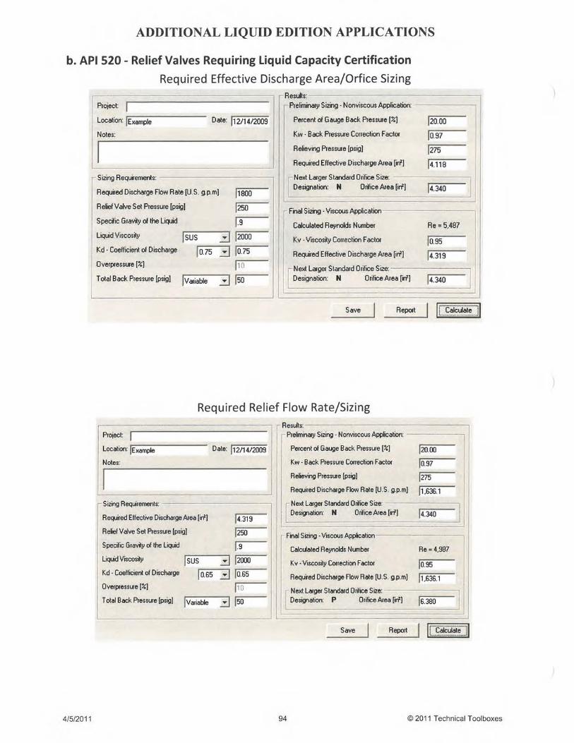
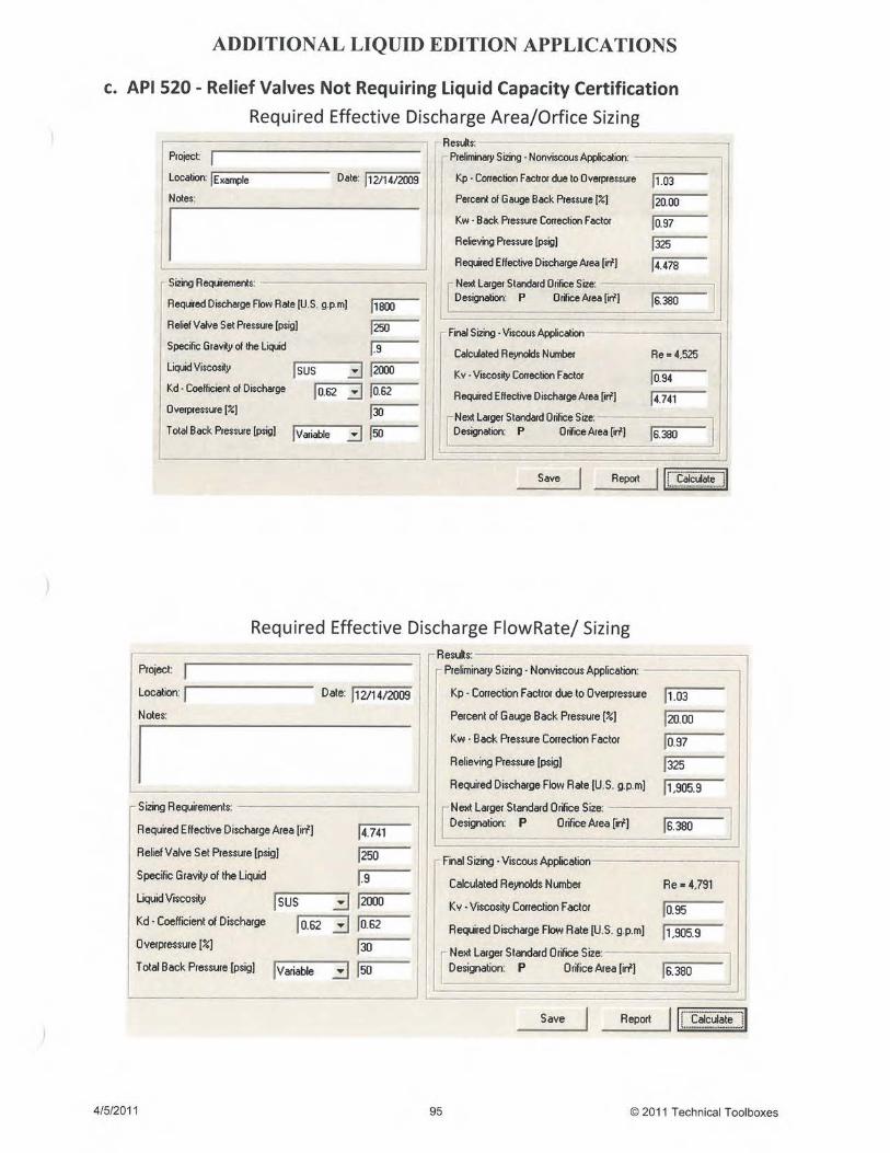
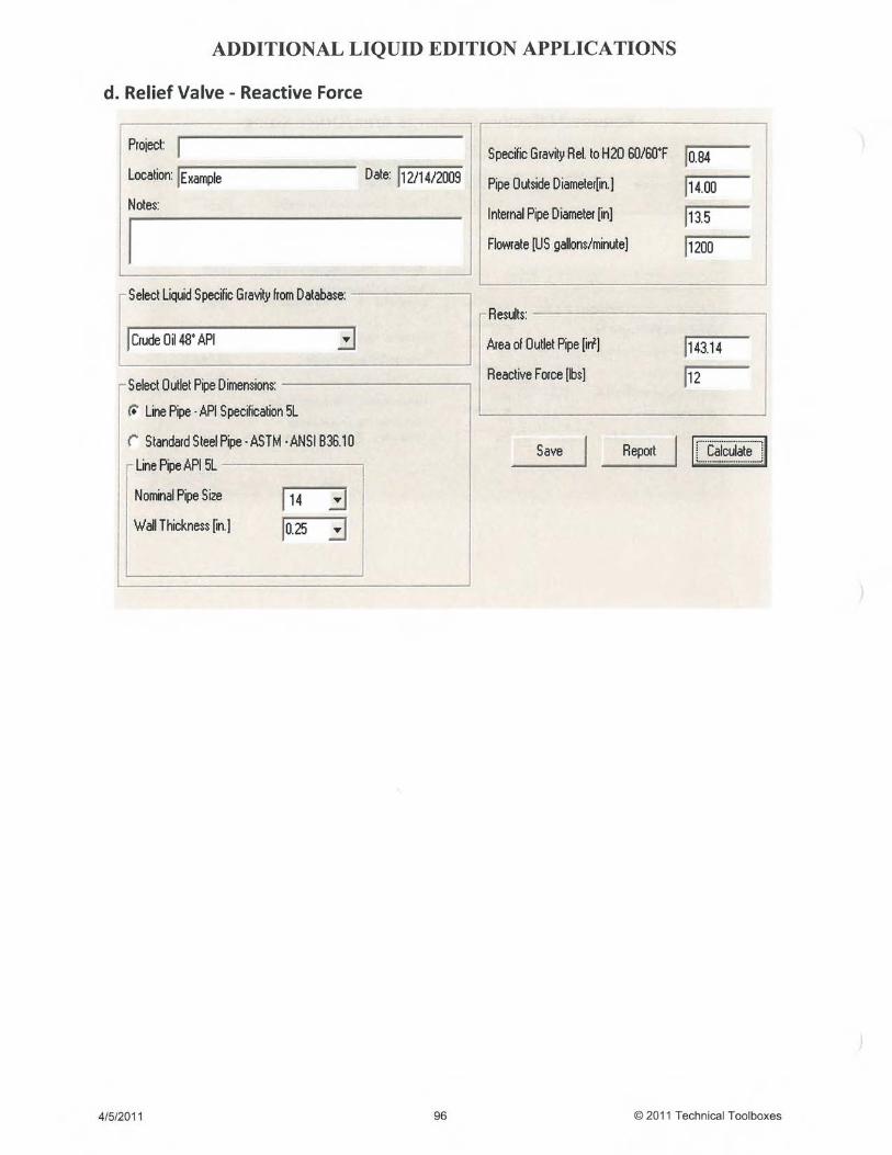
o Relief Valveso Valves Requiring/Not Requiring Liquid
Capacity Certificationo Orifice Area Sizingo Discharge Flow Sizing
o Relief Valve - Reaction Force in an OpenDischarge System (NEW)
ASME Section VIII and API RP 520 Part I - Sizing andSelection, Sixth Edition, March 1993Std Handbook for Mechanical Engineers, McGraw-Hill
API RP 520, Sixth Edition.
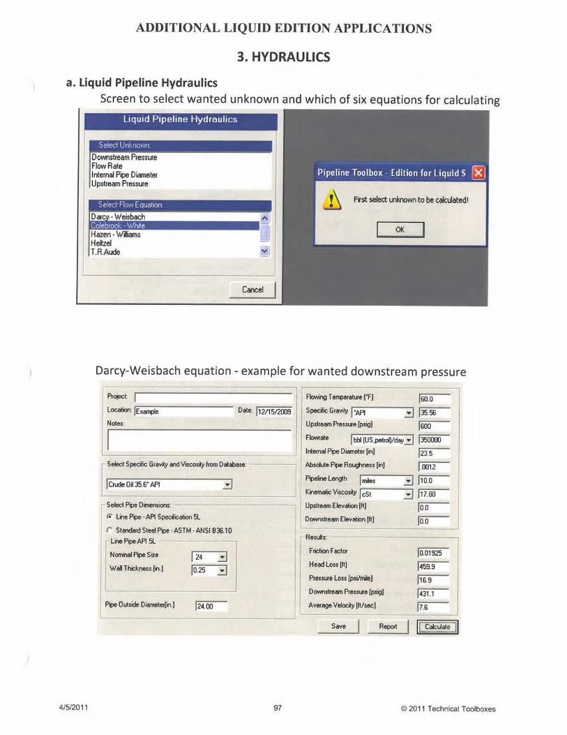
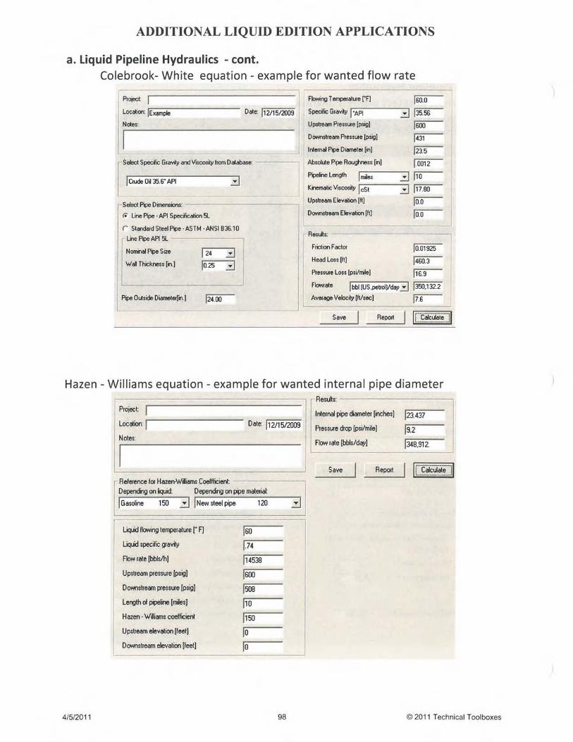
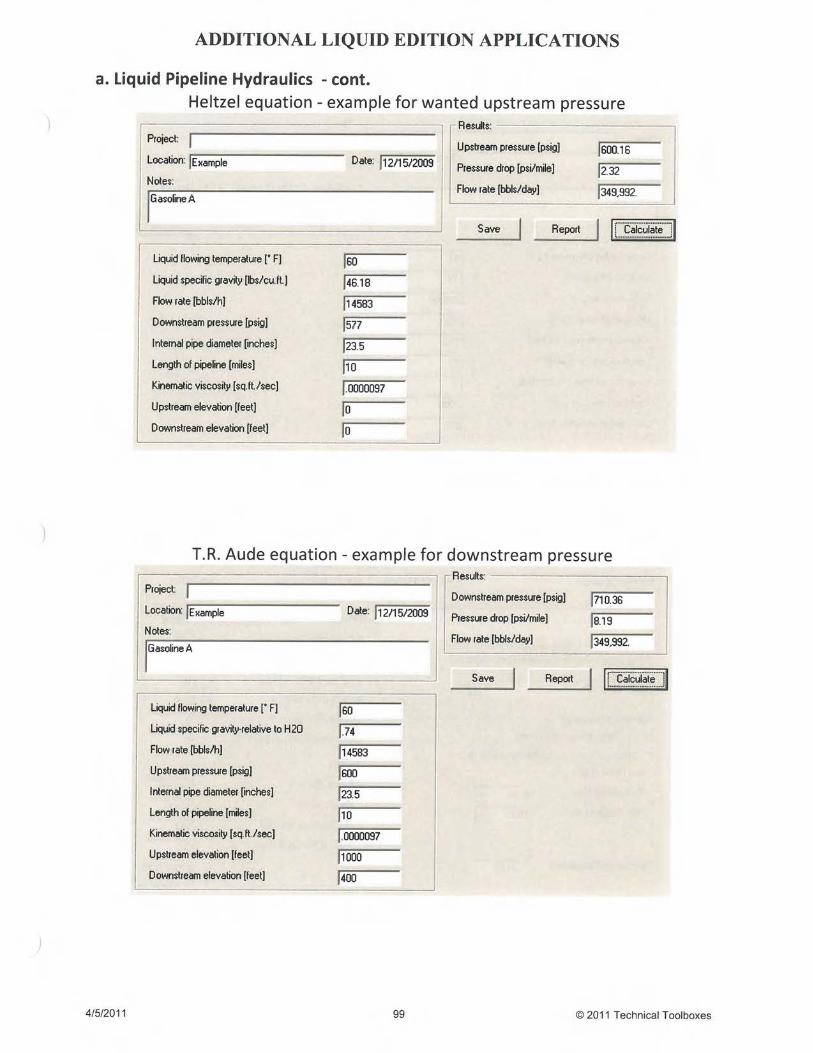
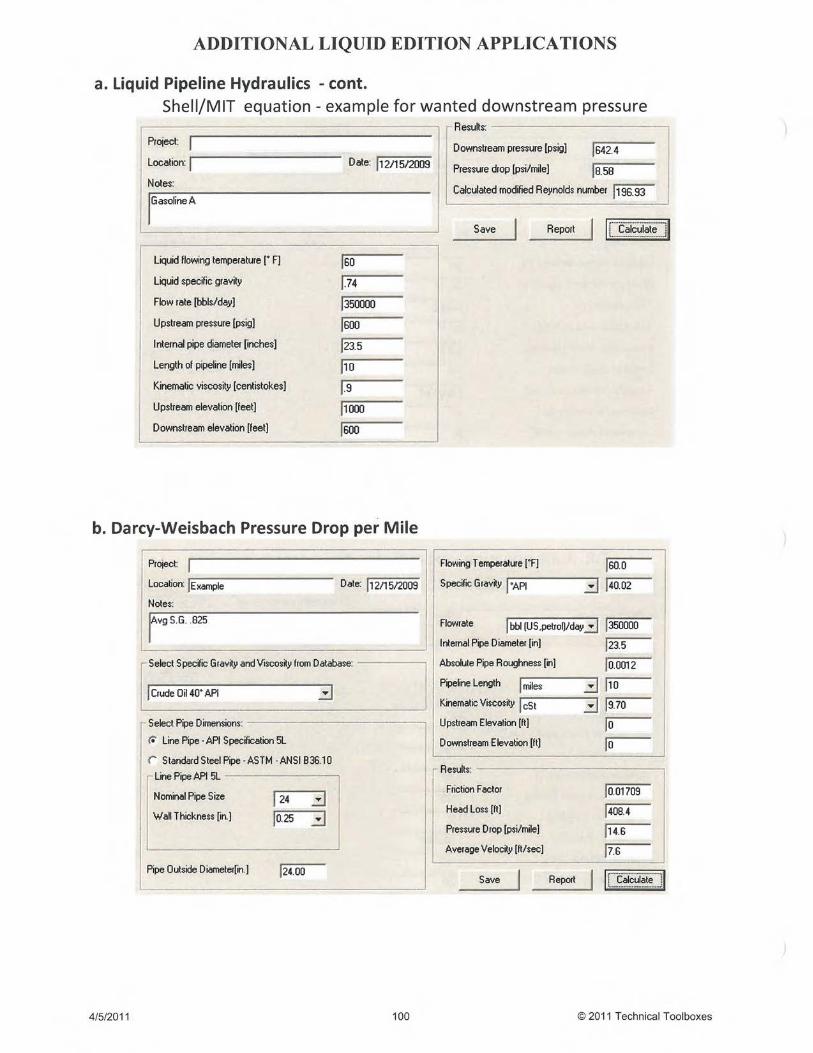
2. Hydraulics2.1 Liquid Pipeline Hydraulics
o Darcy-Weisbacho Colebrook-Whiteo Hazen-Williamso Heltzelo T.R. Audeo Shell/MIT
o Pipeline Design for Hydrocarbons Gases & Liquids,ASCE, Committee on Pipeline Planning
o Hydraulics for Pipeliners, Volume I: Fundamentals,Second Edition, C.B. Lester
o Hydraulics of Pipeline Systems, Bruce E. Larock,Ronald Jeppson, Gary Watters
2.2 Darcy-Weisbach Pressure Drop Per MileFlow of fluids, Technical Paper No.410, CRANEHydraulics for Pipeliners, Volume I:Fundamentals, Second Edition, C.B. Lester
Hydraulics of Pipeline Systems, Bruce E. Larock, RonaldW. Jeppson, Gary Z. Watters
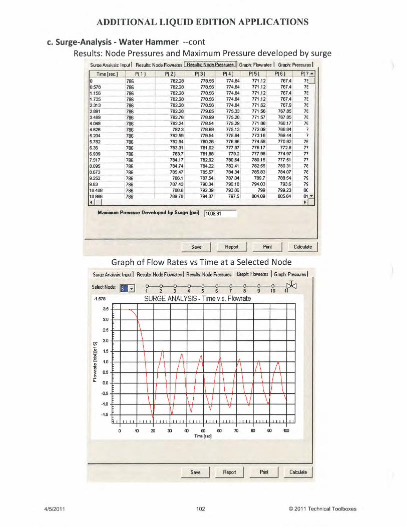
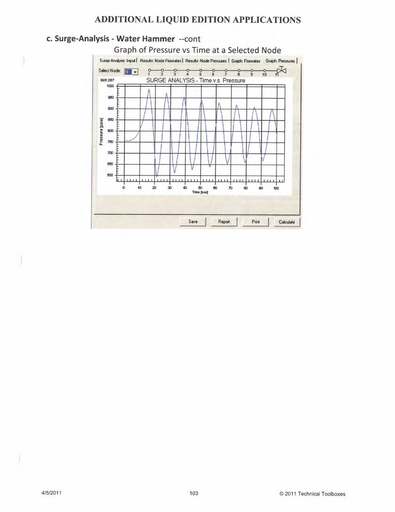
2.3 Surge Analysis – Water Hammer Streeter, V.L. and Wylie, E.B. (1967), Hydraulic Transients,McGraw-Hill,Streeter, V.L. (1969), Waterhammer Analysis. Jour. Hyd. Div.,ASCE., Vol. 88, HY3, pp79-113Streeter, V.L. (1972), Unsteady Flow Calculations by NumericalMethods, ASME Journal of Basic Eng., pp 457-466J. P Tullis (1989), Hydraulic Pipelines, John Wiley & Sons
3. PL Design & Stress Analysis3.1 Design Pressure-Steel Pipe DOT Part 195 & ASME B31.4
5
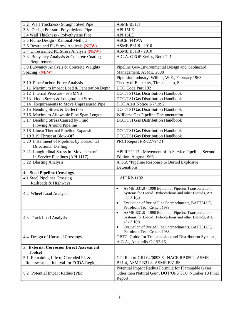
3.2 Wall Thickness- Straight Steel Pipe ASME B31.43.3 Design Pressure-Polyethylene Pipe API 15LE3.4 Wall Thickness - Polyethylene Pipe API 15LE3.5 Flume Design - Rational Method ASCE, FHWA
3.6 Restrained PL Stress Analysis (NEW) ASME B31.8 - 2010
3.7 Unrestrained PL Stress Analysis (NEW) ASME B31.8 - 2010
3.8 Buoyancy Analysis & Concrete CoatingRequirements
A.G.A. GEOP Series, Book T-1
3.9 Buoyancy Analysis & Concrete WeightsSpacing (NEW)
Pipeline Geo-Environmental Design and GeohazardManagement, ASME, 2008
3.10 Pipe Anchor Force AnalysisPipe Line Industry, Wilbur, W.E., February 1963Theory of Elasticity, Timoshenko, S.
3.11 Maximum Impact Load & Penetration Depth DOT Code Part 1923.12 Internal Pressure - % SMYS DOT/TSI Gas Distribution Handbook3.13 Hoop Stress & Longitudinal Stress DOT/TSI Gas Distribution Handbook3.14 Requirements to Move Unpressured Pipe DOT Alert Notice 1/7/19923.15 Bending Stress & Deflection DOT/TSI Gas Distribution Handbook3.16 Maximum Allowable Pipe Span Length Williams Gas Pipeline Documentation3.17 Bending Stress Caused by Fluid
Flowing Around PipelineDOT/TSI Gas Distribution Handbook
3.18 Linear Thermal Pipeline Expansion DOT/TSI Gas Distribution Handbook3.19 3.19 Thrust at Blow-Off DOT/TSI Gas Distribution Handbook3.20 Installment of Pipelines by Horizontal
Directional DrillingPRCI Report PR-227-9424
3.21. Longitudinal Stress in Movement ofIn-Service Pipelines (API 1117)
API RP 1117 - Movement of In-Service Pipeline, SecondEdition, August 1966
3.22 Blasting Analysis A.G.A "Pipeline Response to Buried ExplosiveDetonations
4. Steel Pipeline Crossings4.1 Steel Pipelines Crossing
Railroads & HighwaysAPI RP-1102
4.2 Wheel Load Analysis ASME B31.8 - 1998 Edition of Pipeline Transportation
Systems for Liquid Hydrocarbons and other Liquids, Art.404.3.1(c)
Evaluation of Buried Pipe Encroachments, BATTELLE,Petroleum Tech Center, 1983
4.3 Track Load Analysis ASME B31.8 - 1998 Edition of Pipeline Transportation
Systems for Liquid Hydrocarbons and other Liquids, Art.404.3.1(c)
Evaluation of Buried Pipe Encroachments, BATTELLE,Petroleum Tech Center, 1983
4.4 Design of Uncased Crossings GPTC Guide for Transmission and Distribution Systems,A.G.A., Appendix G-192-15
5. External Corrosion Direct AssessmentToolset
5.1 Remaining Life of Corroded PL &Re-assessment Interval for ECDA Region
GTI Report GRI-04/0093.6, NACE RP 0502, ASMEB31.4, ASME B31.8, ASME B31.8S
5.2 Potential Impact Radius (PIR)Potential Impact Radius Formula for Flammable GasesOther then Natural Gas”, DOT/OPS TTO Number 13 FinalReport
6

5.3 DCVG - % IR Drop CATH- TECH, Cathodic Technology Limited
6. Pipeline Testing
6.1 Pipeline Hydrostatic TestingDOT/TSI Gas Distribution HandbookPipeline Rules of Thumb Handbook, 3rd Edition
6.2 Alternative Acceptance Standards forGirth Welds
API RP 1104 Appendix A (Option-2)
6.3 Pipeline Pressure Testing –Maximum Pressure Drop
DOT/TSI Gas Distribution Handbook
6.4 Pipeline Blowdown – Time/Volume Lost DOT/TSI Gas Distribution Handbook6.5 Purging Calculations DOT/TSI Gas Distribution Handbook6.6 Pack in Pipeline DOT/TSI Gas Distribution Handbook
RSTRENG V5 – Evaluating RemainingStrength of Externally Corroded Pipe
Pipeline Research Council International (PRCI)
7. Pipeline Corrosion7.1 Evaluation of MAOP in Corroded Areas ASME B31G7.2 Maximum Allowable Longitudinal Extent
of CorrosionASME B31G
7.3 Rate of Electrical Current Flow Through theCorrosion Cell
DOT/TSI Gas Distribution Handbook
7.4 Relationship Resistance & Resistivity DOT/TSI Gas Distribution Handbook7.5 Electrolyte Resistance from Surface of
an Electrode to any Distance DOT/TSI Gas Distribution Handbook7.6 Corrosion Current - Ohm’s Law DOT/TSI Gas Distribution Handbook7.7 Electrical Resistance of a Conductor DOT/TSI Gas Distribution Handbook
8. Cathodic Protection8.1 Estimated Weight of a Magnesium Anode DOT/TSI Gas Distribution Handbook8.2 Resistance to Earth of an Impressed Anode
Ground BedDOT/TSI Gas Distribution Handbook
8.3 Rudenberg’s Formula for the Placement ofan Anode Ground Bed
National Association of Corrosion Engineers, Control ofPipeline Corrosion
8.4 Resistance to Earth of a Single VerticalAnode
National Association of Corrosion Engineers, Control ofPipeline Corrosion
8.5 Resistance to Earth of Multiple VerticalAnodes
National Association of Corrosion Engineers, Control ofPipeline Corrosion
8.6 Resistance to Earth of a SingleHorizontal Anode
National Association of Corrosion Engineers, Control ofPipeline Corrosion
8.7 Required Number of Anodes & the TotalCurrent Requirement
National Association of Corrosion Engineers, Control ofPipeline Corrosion
8.8 Power Consumption of a CathodicProtection Rectifier
National Association of Corrosion Engineers, Control ofPipeline Corrosion
8.9 Cathodic Protection Attenuation Calculation ISO 15589 – CP Pipeline Transportation Systems
9. Polyethylene Pipe Design/Stress Analysis9.1 Distributed Static Surcharge Load on
Buried PE Pipe1. Soil Engineering, Spangler, M.G. and Handy, R.L.2. Structural Mechanics of Buried Pipes, Watkins, R.K,
and Loren, R, A,3. Polyethylene Pipe Handbook: Design of PE Piping
Systems, Plastic Pipe Institute, Inc.
9.2 Surcharge Live Load on Buried PEPipe & Pipeline Crossings
7

9.2.1 Aircraft Load on Buried PE Pipe 1. Soil Engineering, Spangler, M.G. and Handy, R.L.2. Structural Mechanics of Buried Pipes, Watkins, R.K,
and Loren, R, A,3. Polyethylene Pipe Handbook: Design of PE Piping
Systems, Plastic Pipe Institute, Inc.9.2.2 AASHTO Std H20 Vehicular Loadingfor Paved & Flexible/Unpaved Surfaces9.2.3 Off Road Crossing-Concentrated PointLoad Single Wheel9.2.4 Off Road Crossing-Concentrated PointLoad Multiple Wheel9.2.5 Off Road Crossing- Concentrated PointLoad Not over Buried PE Pipe9.2.6 Off Road Crossing-Unpaved Road Only(Timoshenko Equation)9.2.7 Cooper E-80 Railroad Load on BuriedPE Pipe
1. Soil Engineering, Spangler, .G. and Handy, R.L.2. Structural Mechanics of Buried Pipes, Watkins, R.K,
and Loren, R, A,3. Polyethylene Pipe Handbook: Design of PE Piping
Systems, Plastic Pipe Institute, Inc.4. Modulus of Soil Reaction for Buried Flexible Pipe,
ASCE Geotechnical Journal Vol. 103, Howard, A.K.5. Evaluation of Modulus of Soil Reaction E’ and Its
Variation with Depth, Report No.UCB/GT/82-02,Duncan,JM/Hartley,JD, Univ. of Calif, Berkeley
9.3 Installation of Polyethylene Pipelinesby Horizontal Directional Drilling(HDD)
9.3.1 PE Pipe – Pull Force & InstallationStress Analysis
ASTM F 1962 05
9.3.2 HDD PE Pipe - ATL Allowable TensileLoad During Pull-In Installation
ASTM F 1962 - 05 and ASTM F 1804 - 08
9.3.3 PE Pipe - Post-Installation StressAnalysis
ASTM F 1962 - 05
10. Data Bases10.1 Physical Properties of Fluids British Gas - GasVLE10.2 Pipe Databases for Steel,
Polyethylene & Custom Pipe Spec. for Line Pipe, API 5L Std Steel Pipe, ASTM B36.10
Spec. for Polyethylene Line Pipe, API 15LE
11. Gas Properties Calculations11.1 Gas Mixture Properties AGA-8 & API MPMS Chapter 14.511.2 Local Atmospheric Pressure AGA Part 3
12. Utilities12.1 Gas Mixture Properties GPA Standard 2172, AGA Report No. 8,API MPMS 14.212.2 Physical Properties of Fluids Various12.3 Document Management Module Application developed by TTI12.4 Applications Integration Module Application developed by TTI
12.5 Units Conversion Module International System of Units (SI) ASTM Metric Guide E380-72E
ANSI Standard Z201.1
13. Standards/Regulations/Forms13.1 Pipeline Safety Laws US Department of Transportation13.2 DOT Regulations US Department of Transportation 49 CFR - Parts 190-19513.3 DOT Forms & Instructions for
ReportingUS Department of Transportation49 CFR - Parts 190-195
13.4 Canadian Pipeline Standards Internet Link provided to CSA website.
8