Embed Size (px)
Citation preview
Seats and Restraint System ............................. 1-1Front Seats ............................................... 1-2Rear Seats ............................................... 1-6Safety Belts ............................................. 1-23Child Restraints ....................................... 1-43Airbag System ......................................... 1-77Restraint System Check ............................ 1-92
Features and Controls ..................................... 2-1Keys ........................................................ 2-3Doors and Locks ...................................... 2-10Windows ................................................. 2-24Theft-Deterrent Systems ............................ 2-27Starting and Operating Your Vehicle ........... 2-31Mirrors .................................................... 2-43Object Detection Systems .......................... 2-44OnStar® System ...................................... 2-47Universal Home Remote System ................ 2-50Storage Areas ......................................... 2-55
Instrument Panel ............................................. 3-1Instrument Panel Overview .......................... 3-4Climate Controls ...................................... 3-22Warning Lights, Gages, and Indicators ........ 3-30Driver Information Center (DIC) .................. 3-43Audio System(s) ....................................... 3-76
Driving Your Vehicle ....................................... 4-1Your Driving, the Road, and the Vehicle ....... 4-2Towing ................................................... 4-24
Service and Appearance Care .......................... 5-1Service ..................................................... 5-3Fuel ......................................................... 5-5Checking Things Under the Hood ............... 5-12Headlamp Aiming ..................................... 5-41Bulb Replacement .................................... 5-41Windshield Wiper Blade Replacement ......... 5-46Tires ...................................................... 5-47Appearance Care ..................................... 5-89Vehicle Identification ................................. 5-97Electrical System ...................................... 5-97Capacities and Specifications ................... 5-104
Maintenance Schedule ..................................... 6-1Maintenance Schedule ................................ 6-2
Customer Assistance Information .................... 7-1Customer Assistance and Information ........... 7-2Reporting Safety Defects ........................... 7-14Vehicle Data Recording and Privacy ........... 7-16
Index ................................................................ 1
2009 Chevrolet Uplander Owner Manual M
GENERAL MOTORS, GM, the GM Emblem,CHEVROLET, the CHEVROLET Emblem, and thename UPLANDER are registered trademarks of GeneralMotors Corporation.
This manual includes the latest information at the time itwas printed. GM reserves the right to make changesafter that time without further notice. For vehiclesfirst sold in Canada, substitute the name “GeneralMotors of Canada Limited” for Chevrolet Motor Divisionwherever it appears in this manual.
This manual describes features that may or may not beon your specific vehicle.
Read this manual from beginning to end to learn aboutthe vehicle’s features and controls. Pictures, symbols,and words work together to explain vehicle operation.
Keep this manual in the vehicle for quick reference.
Canadian OwnersA French language copy of this manual can be obtainedfrom your dealer/retailer or from:
Helm, IncorporatedP.O. Box 07130Detroit, MI 48207
1-800-551-4123helminc.com
Propriétaires CanadiensOn peut obtenir un exemplaire de ce guide en françaisauprès de concessionnaire ou à l’adresse suivante:
Helm IncorporatedP.O. Box 07130Detroit, MI 48207
1-800-551-4123helminc.com
IndexTo quickly locate information about the vehicle use theIndex in the back of the manual. It is an alphabeticallist of what is in the manual and the page number whereit can be found.
Litho in U.S.A.Part No. 15936730 A First Printing ©2008 General Motors Corporation. All Rights Reserved.
ii
Safety Warnings and Symbols
A circle with a slashthrough it is a safetysymbol which means“Do Not,” “Do not do this”or “Do not let this happen.”
A box with the word CAUTION is used to tell aboutthings that could hurt you or others if you were to ignorethe warning.
{CAUTION:
These mean there is something that could hurtyou or other people.
Cautions tell what the hazard is and what to do to avoidor reduce the hazard. Read these cautions.
A notice tells about something that can damage thevehicle.
Notice: These mean there is something that coulddamage your vehicle.
Many times, this damage would not be covered by thevehicle’s warranty, and it could be costly. The noticetells what to do to help avoid the damage.
There are also warning labels on the vehicle which usethe same words, CAUTION or Notice.
iii

✍ NOTES
iv
Front Seats ......................................................1-2Manual Seats ................................................1-2Power Seats ..................................................1-3Heated Seats .................................................1-3Reclining Seatbacks ........................................1-4Head Restraints .............................................1-6
Rear Seats .......................................................1-6Rear Seat Operation .......................................1-6Bucket Seats .................................................1-7Captain Chairs .............................................1-14Third Row Seat ............................................1-18
Safety Belts ...................................................1-23Safety Belts: They Are for Everyone ................1-23How to Wear Safety Belts Properly .................1-28Lap-Shoulder Belt .........................................1-37Safety Belt Use During Pregnancy ..................1-42Safety Belt Extender .....................................1-42
Child Restraints .............................................1-43Older Children ..............................................1-43Infants and Young Children ............................1-46Child Restraint Systems .................................1-49Where to Put the Restraint .............................1-51
Lower Anchors and Tethers forChildren (LATCH) ......................................1-53
Securing a Child Restraint in aRear Seat Position ....................................1-60
Securing a Child Restraint in theRight Front Seat Position ............................1-62
Built-In Child Restraint ...................................1-67Airbag System ...............................................1-77
Where Are the Airbags? ................................1-80When Should an Airbag Inflate? .....................1-82What Makes an Airbag Inflate? .......................1-83How Does an Airbag Restrain? .......................1-83What Will You See After an Airbag Inflates? .....1-84Passenger Sensing System ............................1-85Servicing Your Airbag-Equipped Vehicle ...........1-90Adding Equipment to Your Airbag-Equipped
Vehicle ....................................................1-91Restraint System Check ..................................1-92
Checking the Restraint Systems ......................1-92Replacing Restraint System Parts
After a Crash ............................................1-93
Section 1 Seats and Restraint System
1-1
Front Seats
Manual Seats
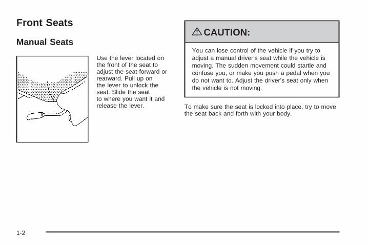
Use the lever located onthe front of the seat toadjust the seat forward orrearward. Pull up onthe lever to unlock theseat. Slide the seatto where you want it andrelease the lever.
{CAUTION:
You can lose control of the vehicle if you try toadjust a manual driver’s seat while the vehicle ismoving. The sudden movement could startle andconfuse you, or make you push a pedal when youdo not want to. Adjust the driver’s seat only whenthe vehicle is not moving.
To make sure the seat is locked into place, try to movethe seat back and forth with your body.
1-2
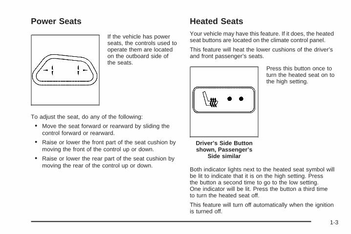
Power Seats
If the vehicle has powerseats, the controls used tooperate them are locatedon the outboard side ofthe seats.
To adjust the seat, do any of the following:
• Move the seat forward or rearward by sliding thecontrol forward or rearward.
• Raise or lower the front part of the seat cushion bymoving the front of the control up or down.
• Raise or lower the rear part of the seat cushion bymoving the rear of the control up or down.
Heated SeatsYour vehicle may have this feature. If it does, the heatedseat buttons are located on the climate control panel.
This feature will heat the lower cushions of the driver’sand front passenger’s seats.
Press this button once toturn the heated seat on tothe high setting.
Both indicator lights next to the heated seat symbol willbe lit to indicate that it is on the high setting. Pressthe button a second time to go to the low setting.One indicator will be lit. Press the button a third timeto turn the heated seat off.
This feature will turn off automatically when the ignitionis turned off.
Driver’s Side Buttonshown, Passenger’s
Side similar
1-3
Reclining Seatbacks
{CAUTION:
You can lose control of the vehicle if you try toadjust a manual driver’s seat while the vehicle ismoving. The sudden movement could startle andconfuse you, or make you push a pedal when youdo not want to. Adjust the driver’s seat only whenthe vehicle is not moving.
{CAUTION:
If the seatback is not locked, it could moveforward in a sudden stop or crash. That couldcause injury to the person sitting there. Alwayspush and pull on the seatback to be sure it islocked.
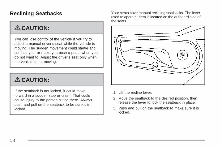
Your seats have manual reclining seatbacks. The leverused to operate them is located on the outboard side ofthe seats.
1. Lift the recline lever.
2. Move the seatback to the desired position, thenrelease the lever to lock the seatback in place.
3. Push and pull on the seatback to make sure it islocked.
1-4

To return the seatback to an upright position, do thefollowing:
1. Lift the lever fully without applying pressure to theseatback and the seatback will return to the uprightposition.
2. Push and pull on the seatback to make sure it islocked.
{CAUTION:
Sitting in a reclined position when your vehicle isin motion can be dangerous. Even if you buckleup, your safety belts cannot do their job when youare reclined like this.
The shoulder belt cannot do its job because it willnot be against your body. Instead, it will be in frontof you. In a crash, you could go into it, receivingneck or other injuries.
The lap belt cannot do its job either. In a crash,the belt could go up over your abdomen. The beltforces would be there, not at your pelvic bones.This could cause serious internal injuries.
For proper protection when the vehicle is in motion,have the seatback upright. Then sit well back in theseat and wear your safety belt properly.
Do not have a seatback reclined if your vehicle ismoving.
1-5
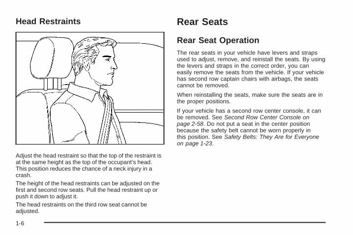
Head Restraints
Adjust the head restraint so that the top of the restraint isat the same height as the top of the occupant’s head.This position reduces the chance of a neck injury in acrash.The height of the head restraints can be adjusted on thefirst and second row seats. Pull the head restraint up orpush it down to adjust it.The head restraints on the third row seat cannot beadjusted.
Rear Seats
Rear Seat OperationThe rear seats in your vehicle have levers and strapsused to adjust, remove, and reinstall the seats. By usingthe levers and straps in the correct order, you caneasily remove the seats from the vehicle. If your vehiclehas second row captain chairs with airbags, the seatscannot be removed.
When reinstalling the seats, make sure the seats are inthe proper positions.
If your vehicle has a second row center console, it canbe removed. See Second Row Center Console onpage 2-58. Do not put a seat in the center positionbecause the safety belt cannot be worn properly inthis position. See Safety Belts: They Are for Everyoneon page 1-23.
1-6
Bucket SeatsThe vehicle may have bucket seats in the second row.These seats can be adjusted several different ways.
Fold and Tumble Feature
{CAUTION:
Using the third row seating position while thesecond row is folded, or folded and tumbled, couldcause injury in a sudden stop or crash. Be sure toreturn the seat to the passenger seating position.Push and pull on the seat to make sure it islocked into place.
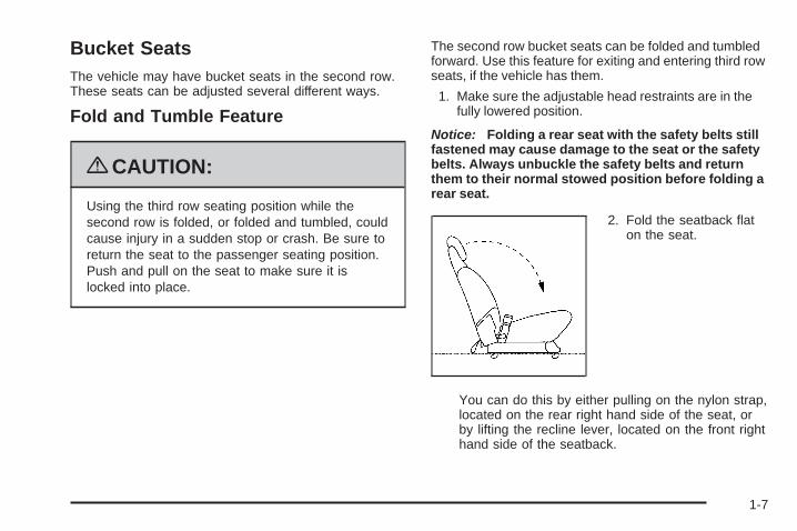
The second row bucket seats can be folded and tumbledforward. Use this feature for exiting and entering third rowseats, if the vehicle has them.
1. Make sure the adjustable head restraints are in thefully lowered position.
Notice: Folding a rear seat with the safety belts stillfastened may cause damage to the seat or the safetybelts. Always unbuckle the safety belts and returnthem to their normal stowed position before folding arear seat.
2. Fold the seatback flaton the seat.
You can do this by either pulling on the nylon strap,located on the rear right hand side of the seat, orby lifting the recline lever, located on the front righthand side of the seatback.
1-7
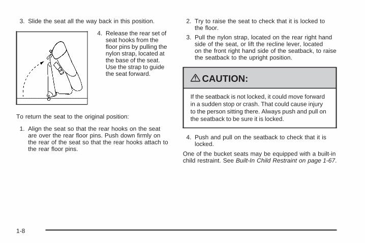
3. Slide the seat all the way back in this position.
4. Release the rear set ofseat hooks from thefloor pins by pulling thenylon strap, located atthe base of the seat.Use the strap to guidethe seat forward.
To return the seat to the original position:
1. Align the seat so that the rear hooks on the seatare over the rear floor pins. Push down firmly onthe rear of the seat so that the rear hooks attach tothe rear floor pins.
2. Try to raise the seat to check that it is locked tothe floor.
3. Pull the nylon strap, located on the rear right handside of the seat, or lift the recline lever, locatedon the front right hand side of the seatback, to raisethe seatback to the upright position.
{CAUTION:
If the seatback is not locked, it could move forwardin a sudden stop or crash. That could cause injuryto the person sitting there. Always push and pull onthe seatback to be sure it is locked.
4. Push and pull on the seatback to check that it islocked.
One of the bucket seats may be equipped with a built-inchild restraint. See Built-In Child Restraint on page 1-67.
1-8
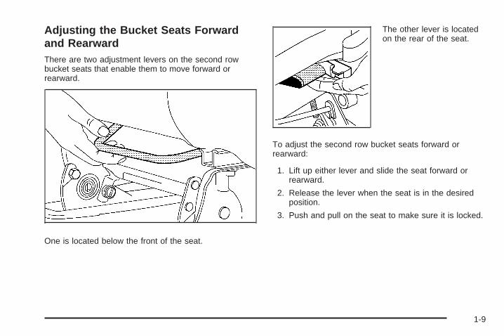
Adjusting the Bucket Seats Forwardand RearwardThere are two adjustment levers on the second rowbucket seats that enable them to move forward orrearward.
One is located below the front of the seat.
The other lever is locatedon the rear of the seat.
To adjust the second row bucket seats forward orrearward:
1. Lift up either lever and slide the seat forward orrearward.
2. Release the lever when the seat is in the desiredposition.
3. Push and pull on the seat to make sure it is locked.
1-9
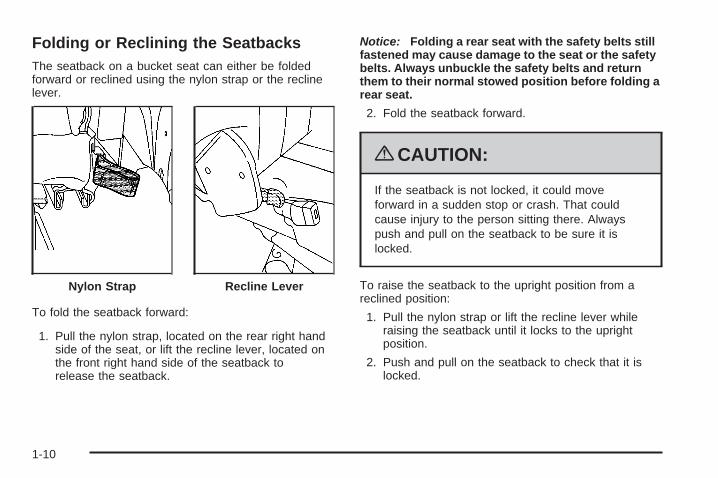
Folding or Reclining the SeatbacksThe seatback on a bucket seat can either be foldedforward or reclined using the nylon strap or the reclinelever.
To fold the seatback forward:
1. Pull the nylon strap, located on the rear right handside of the seat, or lift the recline lever, located onthe front right hand side of the seatback torelease the seatback.
Notice: Folding a rear seat with the safety belts stillfastened may cause damage to the seat or the safetybelts. Always unbuckle the safety belts and returnthem to their normal stowed position before folding arear seat.
2. Fold the seatback forward.
{CAUTION:
If the seatback is not locked, it could moveforward in a sudden stop or crash. That couldcause injury to the person sitting there. Alwayspush and pull on the seatback to be sure it islocked.
To raise the seatback to the upright position from areclined position:
1. Pull the nylon strap or lift the recline lever whileraising the seatback until it locks to the uprightposition.
2. Push and pull on the seatback to check that it islocked.
Nylon Strap Recline Lever
1-10
To recline the seatback:
1. Pull the nylon strap or lift the recline lever.
2. Press back on the seatback until it is in the desiredposition
3. Let go of the strap or lever.
Removing the Bucket SeatsTo remove the bucket seats:
1. Make sure the head restraint is in the fully loweredposition.
Notice: Folding a rear seat with the safety beltsstill fastened may cause damage to the seat or thesafety belts. Always unbuckle the safety beltsand return them to their normal stowed positionbefore folding a rear seat.
2. Fold the seatback flat on the seat, by either pullingon the nylon strap, located on the rear right handside of the seat, or by lifting the recline lever,located on the front right hand side of the seatback.
3. Lift either one of the adjuster levers and slide theseat to the most rearward position. See “Adjustingthe Bucket Seats Forward and Rearward” earlierin this section.
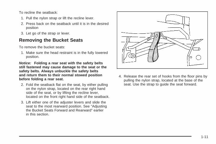
4. Release the rear set of hooks from the floor pins bypulling the nylon strap, located at the base of theseat. Use the strap to guide the seat forward.
1-11
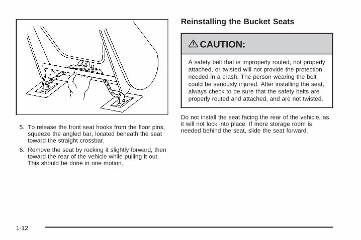
5. To release the front seat hooks from the floor pins,squeeze the angled bar, located beneath the seattoward the straight crossbar.
6. Remove the seat by rocking it slightly forward, thentoward the rear of the vehicle while pulling it out.This should be done in one motion.
Reinstalling the Bucket Seats
{CAUTION:
A safety belt that is improperly routed, not properlyattached, or twisted will not provide the protectionneeded in a crash. The person wearing the beltcould be seriously injured. After installing the seat,always check to be sure that the safety belts areproperly routed and attached, and are not twisted.
Do not install the seat facing the rear of the vehicle, asit will not lock into place. If more storage room isneeded behind the seat, slide the seat forward.
1-12
Make sure the seat is in the full rear position beforebeginning this procedure.
To reinstall the bucket seats:
1. With the seat folded, squeeze the angled barbeneath the seat toward the straight crossbar, whileplacing the front hooks of the seat into the fronttwo floor pins.
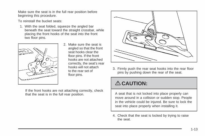
2. Make sure the seat isangled so that the frontseat hooks clear thefloor pins. If the fronthooks are not attachedcorrectly, the seat’s rearhooks will not attachto the rear set offloor pins.
If the front hooks are not attaching correctly, checkthat the seat is in the full rear position.
3. Firmly push the rear seat hooks into the rear floorpins by pushing down the rear of the seat.
{CAUTION:
A seat that is not locked into place properly canmove around in a collision or sudden stop. Peoplein the vehicle could be injured. Be sure to lock theseat into place properly when installing it.
4. Check that the seat is locked by trying to raisethe seat.
1-13
5. Pull the nylon strap, located on the rear right handside of the seat, or lift the recline lever, located onthe front right hand side of the seatback, toraise the seatback to the upright position.
{CAUTION:
If the seatback is not locked, it could moveforward in a sudden stop or crash. That couldcause injury to the person sitting there. Alwayspush and pull on the seatback to be sure it islocked.
6. Push and pull on the seatback to make sure that itis locked.
Captain ChairsYour vehicle may have second row captain chairs. If so,they can be adjusted forward or rearward and theseatbacks can be adjusted.
Adjusting the Captain Chairs Forwardand RearwardThere are two manual adjustment bars on each seat. Oneis located under the front of the seat cushion. The otherone is located under the rear of the seat cushion.
Lift up either bar to slide the seat forward or rearward.Release the lever. Push and pull on the seat tomake sure it is locked into place.
Folding or Reclining the Seatbacks
{CAUTION:
If the seatback is not locked, it could move forwardin a sudden stop or crash. That could cause injuryto the person sitting there. Always push and pull onthe seatback to be sure it is locked.
1-14
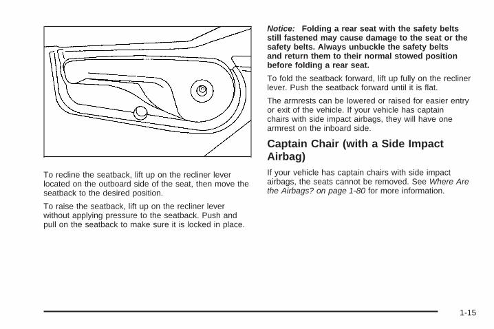
To recline the seatback, lift up on the recliner leverlocated on the outboard side of the seat, then move theseatback to the desired position.
To raise the seatback, lift up on the recliner leverwithout applying pressure to the seatback. Push andpull on the seatback to make sure it is locked in place.
Notice: Folding a rear seat with the safety beltsstill fastened may cause damage to the seat or thesafety belts. Always unbuckle the safety beltsand return them to their normal stowed positionbefore folding a rear seat.
To fold the seatback forward, lift up fully on the reclinerlever. Push the seatback forward until it is flat.
The armrests can be lowered or raised for easier entryor exit of the vehicle. If your vehicle has captainchairs with side impact airbags, they will have onearmrest on the inboard side.
Captain Chair (with a Side ImpactAirbag)If your vehicle has captain chairs with side impactairbags, the seats cannot be removed. See Where Arethe Airbags? on page 1-80 for more information.
1-15
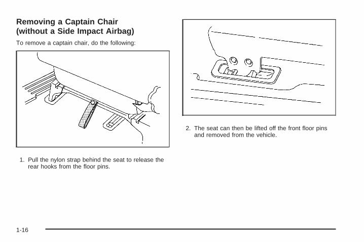
Removing a Captain Chair(without a Side Impact Airbag)To remove a captain chair, do the following:
1. Pull the nylon strap behind the seat to release therear hooks from the floor pins.
2. The seat can then be lifted off the front floor pinsand removed from the vehicle.
1-16
Installing a Captain Chair(without a Side Impact Airbag)
{CAUTION:
A safety belt that is improperly routed, not properlyattached, or twisted will not provide the protectionneeded in a crash. The person wearing the beltcould be seriously injured. After installing the seat,always check to be sure that the safety belts areproperly routed and attached, and are not twisted.
Do not put the seats in so they face rearward becausethey will not latch that way. For the second row, ifyou want more storage room behind the seat, adjust theseat by sliding it forward.
Make sure the seatbacks are in the upright position,the seat belts are on the correct side of the seats andthe seats are in the full rear position before beginningthis procedure.
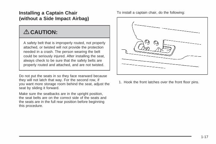
To install a captain chair, do the following:
1. Hook the front latches over the front floor pins.
1-17
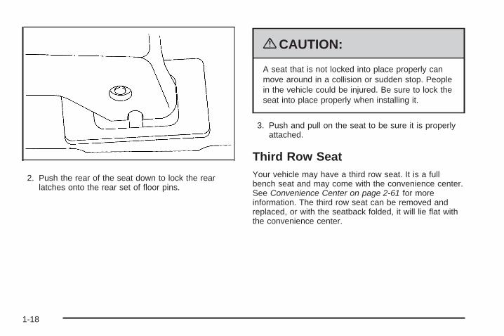
2. Push the rear of the seat down to lock the rearlatches onto the rear set of floor pins.
{CAUTION:
A seat that is not locked into place properly canmove around in a collision or sudden stop. Peoplein the vehicle could be injured. Be sure to lock theseat into place properly when installing it.
3. Push and pull on the seat to be sure it is properlyattached.
Third Row SeatYour vehicle may have a third row seat. It is a fullbench seat and may come with the convenience center.See Convenience Center on page 2-61 for moreinformation. The third row seat can be removed andreplaced, or with the seatback folded, it will lie flat withthe convenience center.
1-18
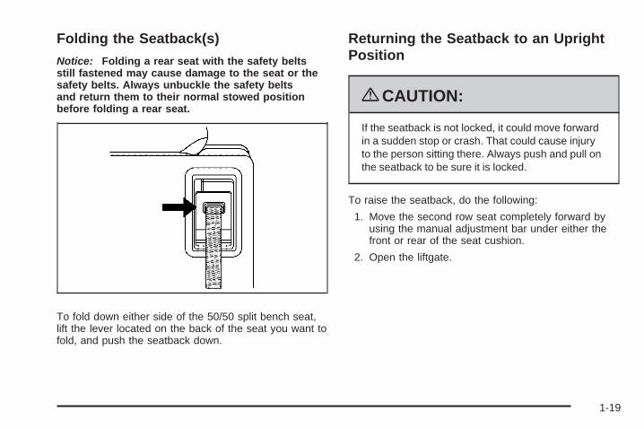
Folding the Seatback(s)
Notice: Folding a rear seat with the safety beltsstill fastened may cause damage to the seat or thesafety belts. Always unbuckle the safety beltsand return them to their normal stowed positionbefore folding a rear seat.
To fold down either side of the 50/50 split bench seat,lift the lever located on the back of the seat you want tofold, and push the seatback down.
Returning the Seatback to an UprightPosition
{CAUTION:
If the seatback is not locked, it could move forwardin a sudden stop or crash. That could cause injuryto the person sitting there. Always push and pull onthe seatback to be sure it is locked.
To raise the seatback, do the following:
1. Move the second row seat completely forward byusing the manual adjustment bar under either thefront or rear of the seat cushion.
2. Open the liftgate.
1-19
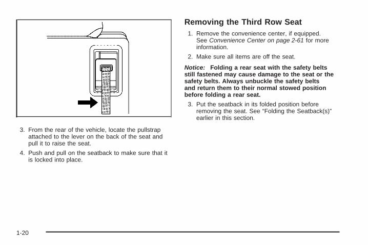
3. From the rear of the vehicle, locate the pullstrapattached to the lever on the back of the seat andpull it to raise the seat.
4. Push and pull on the seatback to make sure that itis locked into place.
Removing the Third Row Seat1. Remove the convenience center, if equipped.
See Convenience Center on page 2-61 for moreinformation.
2. Make sure all items are off the seat.
Notice: Folding a rear seat with the safety beltsstill fastened may cause damage to the seat or thesafety belts. Always unbuckle the safety beltsand return them to their normal stowed positionbefore folding a rear seat.
3. Put the seatback in its folded position beforeremoving the seat. See “Folding the Seatback(s)”earlier in this section.
1-20
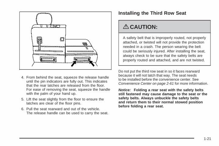
4. From behind the seat, squeeze the release handleuntil the pin indicators are fully out. This indicatesthat the rear latches are released from the floor.For ease of removing the seat, squeeze the handlewith the palm of your hand up.
5. Lift the seat slightly from the floor to ensure thelatches are clear of the floor pins.
6. Pull the seat rearward and out of the vehicle.The release handle can be used to carry the seat.
Installing the Third Row Seat
{CAUTION:
A safety belt that is improperly routed, not properlyattached, or twisted will not provide the protectionneeded in a crash. The person wearing the beltcould be seriously injured. After installing the seat,always check to be sure that the safety belts areproperly routed and attached, and are not twisted.
Do not put the third row seat in so it faces rearwardbecause it will not latch that way. The seat needsto be installed before the convenience center. SeeConvenience Center on page 2-61 for more information.
Notice: Folding a rear seat with the safety beltsstill fastened may cause damage to the seat or thesafety belts. Always unbuckle the safety beltsand return them to their normal stowed positionbefore folding a rear seat.
1-21
For ease of installing the seat, put the seat in the foldedposition before beginning this procedure.
1. From the rear of the vehicle, place the front hooksof the seat onto the front floor pins in the third row.To do this, the seat will need to be angledapproximately 8-10 inches (20-25 cm) from the floorso the front hooks clear the rear floor pins andrear floor cups. Use the release handle to guidethe seat into place.If the front hooks are not attached correctly, therear latches will not attach to the rear set offloor pins.
2. Firmly push the rear latches into the rear floor pinsby pushing down on the rear of the seat.
{CAUTION:
A seat that is not locked into place properly canmove around in a collision or sudden stop. Peoplein the vehicle could be injured. Be sure to lock theseat into place properly when installing it.
3. Try to raise the seat to make sure that it is lockeddown. The indicator pins will no longer stick outwhen the seat is properly latched into place.
{CAUTION:
If the seatback is not locked, it could moveforward in a sudden stop or crash. That couldcause injury to the person sitting there. Alwayspush and pull on the seatback to be sure it islocked.
4. Return the seatback to its upright position. See“Returning the Seatback to an Upright Position”earlier in this section.
1-22

Safety Belts
Safety Belts: They Are for EveryoneThis section of the manual describes how to usesafety belts properly. It also describes some things notto do with safety belts.
{CAUTION:
Do not let anyone ride where a safety belt cannotbe worn properly. In a crash, if you or yourpassenger(s) are not wearing safety belts, theinjuries can be much worse. You can hit thingsinside the vehicle harder or be ejected from thevehicle. You and your passenger(s) can beseriously injured or killed. In the same crash, youmight not be, if you are buckled up. Always fastenyour safety belt, and check that your passenger(s)are restrained properly too.
{CAUTION:
It is extremely dangerous to ride in a cargo area,inside or outside of a vehicle. In a collision, peopleriding in these areas are more likely to be seriouslyinjured or killed. Do not allow people to ride in anyarea of your vehicle that is not equipped with seatsand safety belts. Be sure everyone in your vehicle isin a seat and using a safety belt properly.
This vehicle has indicators as a reminder to buckle thesafety belts. See Safety Belt Reminders on page 3-32for additional information.
1-23
In most states and in all Canadian provinces, the lawrequires wearing safety belts. Here is why:
You never know if you will be in a crash. If you do havea crash, you do not know if it will be a serious one.
A few crashes are mild, and some crashes can be soserious that even buckled up, a person would notsurvive. But most crashes are in between. In many ofthem, people who buckle up can survive and sometimeswalk away. Without safety belts, they could havebeen badly hurt or killed.
After more than 40 years of safety belts in vehicles, thefacts are clear. In most crashes buckling up doesmatter... a lot!
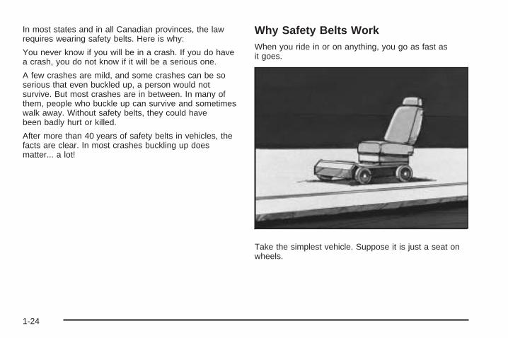
Why Safety Belts WorkWhen you ride in or on anything, you go as fast asit goes.
Take the simplest vehicle. Suppose it is just a seat onwheels.
1-24
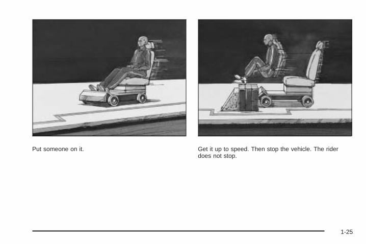
Put someone on it. Get it up to speed. Then stop the vehicle. The riderdoes not stop.
1-25

The person keeps going until stopped by something.In a real vehicle, it could be the windshield...
or the instrument panel...
1-26
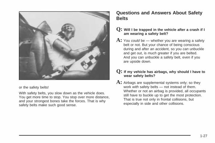
or the safety belts!
With safety belts, you slow down as the vehicle does.You get more time to stop. You stop over more distance,and your strongest bones take the forces. That is whysafety belts make such good sense.
Questions and Answers About SafetyBelts
Q: Will I be trapped in the vehicle after a crash if Iam wearing a safety belt?
A: You could be — whether you are wearing a safetybelt or not. But your chance of being consciousduring and after an accident, so you can unbuckleand get out, is much greater if you are belted.And you can unbuckle a safety belt, even if youare upside down.
Q: If my vehicle has airbags, why should I have towear safety belts?
A: Airbags are supplemental systems only; so theywork with safety belts — not instead of them.Whether or not an airbag is provided, all occupantsstill have to buckle up to get the most protection.That is true not only in frontal collisions, butespecially in side and other collisions.
1-27
Q: If I am a good driver, and I never drive far fromhome, why should I wear safety belts?
A: You may be an excellent driver, but if you are in acrash — even one that is not your fault — you andyour passenger(s) can be hurt. Being a good driverdoes not protect you from things beyond yourcontrol, such as bad drivers.
Most accidents occur within 25 miles (40 km)of home. And the greatest number of seriousinjuries and deaths occur at speeds of less than40 mph (65 km/h).
Safety belts are for everyone.
How to Wear Safety Belts ProperlyThis section is only for people of adult size.
Be aware that there are special things to know aboutsafety belts and children. And there are differentrules for smaller children and infants. If a child will beriding in the vehicle, see Older Children on page 1-43 orInfants and Young Children on page 1-46. Followthose rules for everyone’s protection.
It is very important for all occupants to buckle up.Statistics show that unbelted people are hurt more oftenin crashes than those who are wearing safety belts.
Occupants who are not buckled up can be thrown out ofthe vehicle in a crash. And they can strike others inthe vehicle who are wearing safety belts.
First, before you or your passenger(s) wear a safetybelt, there is important information you should know.
1-28
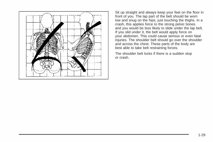
Sit up straight and always keep your feet on the floor infront of you. The lap part of the belt should be wornlow and snug on the hips, just touching the thighs. In acrash, this applies force to the strong pelvic bonesand you would be less likely to slide under the lap belt.If you slid under it, the belt would apply force onyour abdomen. This could cause serious or even fatalinjuries. The shoulder belt should go over the shoulderand across the chest. These parts of the body arebest able to take belt restraining forces.
The shoulder belt locks if there is a sudden stopor crash.
1-29
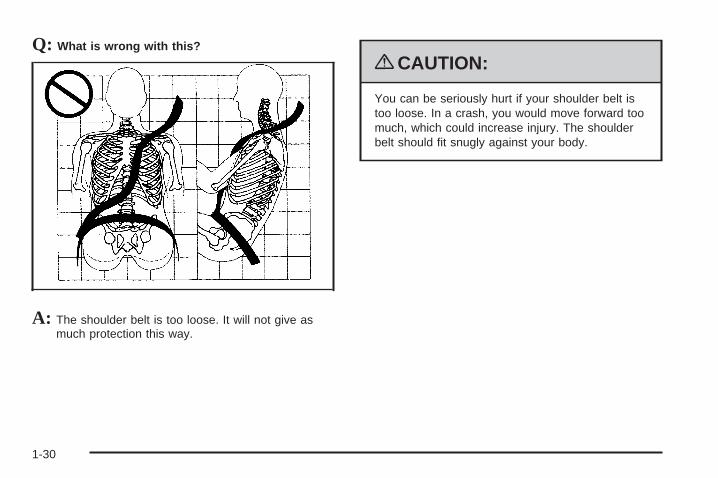
Q: What is wrong with this?
A: The shoulder belt is too loose. It will not give asmuch protection this way.
{CAUTION:
You can be seriously hurt if your shoulder belt istoo loose. In a crash, you would move forward toomuch, which could increase injury. The shoulderbelt should fit snugly against your body.
1-30
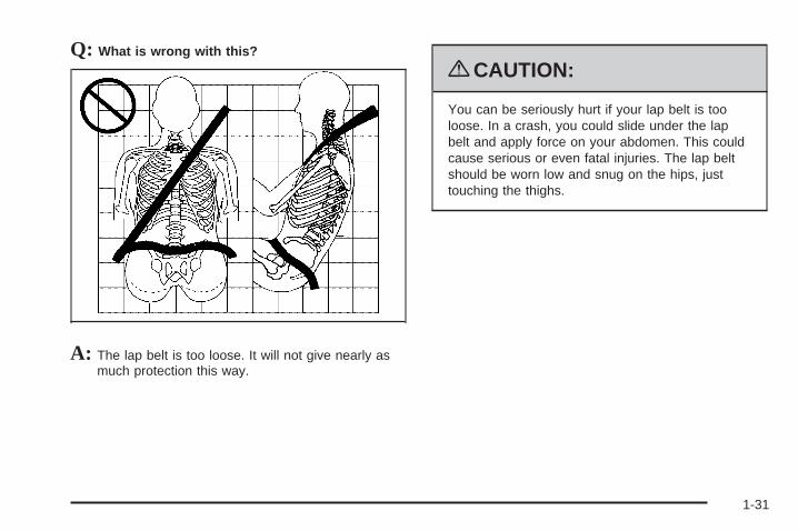
Q: What is wrong with this?
A: The lap belt is too loose. It will not give nearly asmuch protection this way.
{CAUTION:
You can be seriously hurt if your lap belt is tooloose. In a crash, you could slide under the lapbelt and apply force on your abdomen. This couldcause serious or even fatal injuries. The lap beltshould be worn low and snug on the hips, justtouching the thighs.
1-31
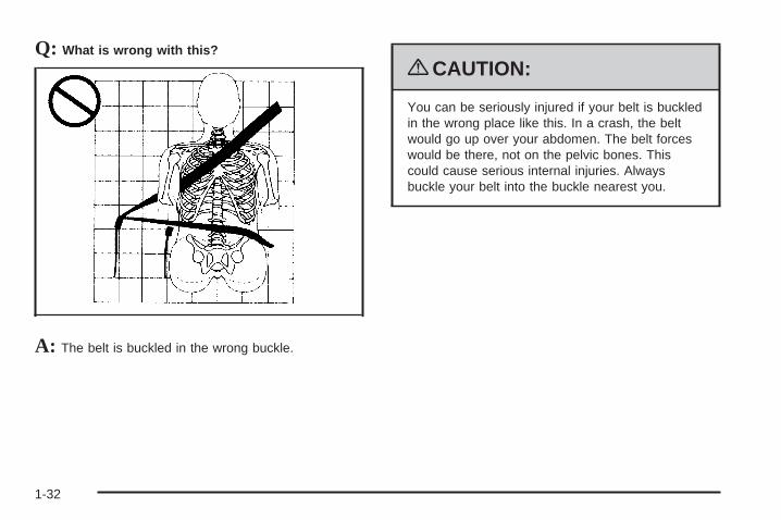
Q: What is wrong with this?
A: The belt is buckled in the wrong buckle.
{CAUTION:
You can be seriously injured if your belt is buckledin the wrong place like this. In a crash, the beltwould go up over your abdomen. The belt forceswould be there, not on the pelvic bones. Thiscould cause serious internal injuries. Alwaysbuckle your belt into the buckle nearest you.
1-32
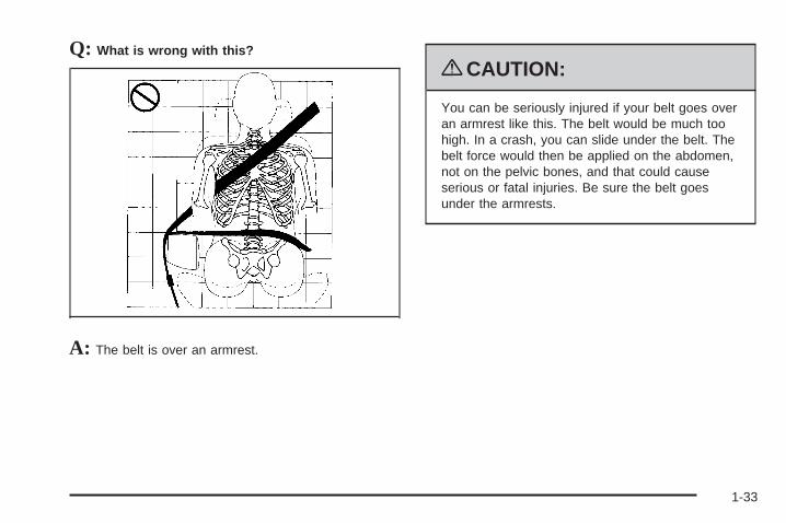
Q: What is wrong with this?
A: The belt is over an armrest.
{CAUTION:
You can be seriously injured if your belt goes overan armrest like this. The belt would be much toohigh. In a crash, you can slide under the belt. Thebelt force would then be applied on the abdomen,not on the pelvic bones, and that could causeserious or fatal injuries. Be sure the belt goesunder the armrests.
1-33

Q: What is wrong with this?
A: The shoulder belt is worn under the arm. It shouldbe worn over the shoulder at all times.
{CAUTION:
You can be seriously injured if you wear theshoulder belt under your arm. In a crash, yourbody would move too far forward, which wouldincrease the chance of head and neck injury. Also,the belt would apply too much force to the ribs,which are not as strong as shoulder bones. Youcould also severely injure internal organs like yourliver or spleen. The shoulder belt should go overthe shoulder and across the chest.
1-34
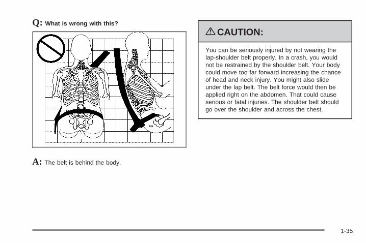
Q: What is wrong with this?
A: The belt is behind the body.
{CAUTION:
You can be seriously injured by not wearing thelap-shoulder belt properly. In a crash, you wouldnot be restrained by the shoulder belt. Your bodycould move too far forward increasing the chanceof head and neck injury. You might also slideunder the lap belt. The belt force would then beapplied right on the abdomen. That could causeserious or fatal injuries. The shoulder belt shouldgo over the shoulder and across the chest.
1-35
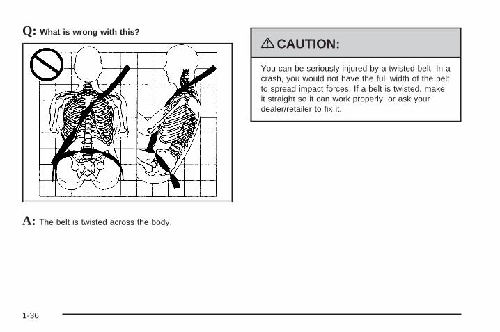
Q: What is wrong with this?
A: The belt is twisted across the body.
{CAUTION:
You can be seriously injured by a twisted belt. In acrash, you would not have the full width of the beltto spread impact forces. If a belt is twisted, makeit straight so it can work properly, or ask yourdealer/retailer to fix it.
1-36
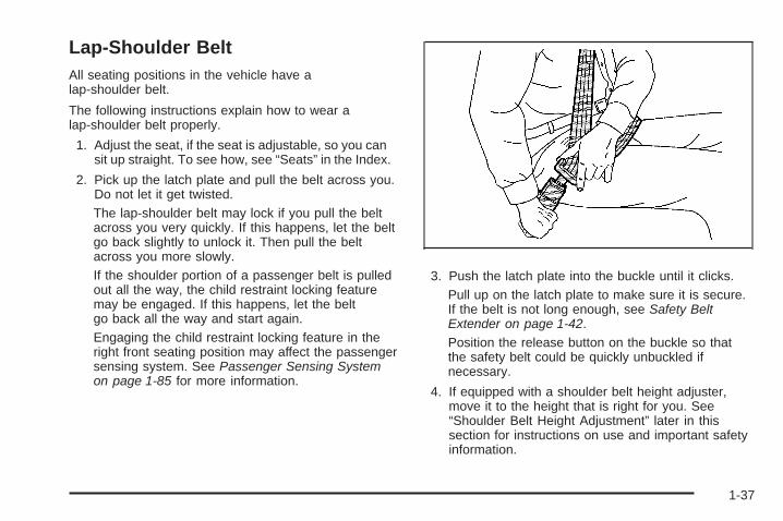
Lap-Shoulder BeltAll seating positions in the vehicle have alap-shoulder belt.
The following instructions explain how to wear alap-shoulder belt properly.
1. Adjust the seat, if the seat is adjustable, so you cansit up straight. To see how, see “Seats” in the Index.
2. Pick up the latch plate and pull the belt across you.Do not let it get twisted.The lap-shoulder belt may lock if you pull the beltacross you very quickly. If this happens, let the beltgo back slightly to unlock it. Then pull the beltacross you more slowly.If the shoulder portion of a passenger belt is pulledout all the way, the child restraint locking featuremay be engaged. If this happens, let the beltgo back all the way and start again.Engaging the child restraint locking feature in theright front seating position may affect the passengersensing system. See Passenger Sensing Systemon page 1-85 for more information.
3. Push the latch plate into the buckle until it clicks.Pull up on the latch plate to make sure it is secure.If the belt is not long enough, see Safety BeltExtender on page 1-42.Position the release button on the buckle so thatthe safety belt could be quickly unbuckled ifnecessary.
4. If equipped with a shoulder belt height adjuster,move it to the height that is right for you. See“Shoulder Belt Height Adjustment” later in thissection for instructions on use and important safetyinformation.
1-37

5. To make the lap part tight, pull up on theshoulder belt.It may be necessary to pull stitching on the safetybelt through the latch plate to fully tighten thelap belt on smaller occupants.
To unlatch the belt, push the button on the buckle.The belt should return to its stowed position.
Before a door is closed, be sure the safety belt is out ofthe way. If a door is slammed against a safety belt,damage can occur to both the safety belt and the vehicle.
1-38
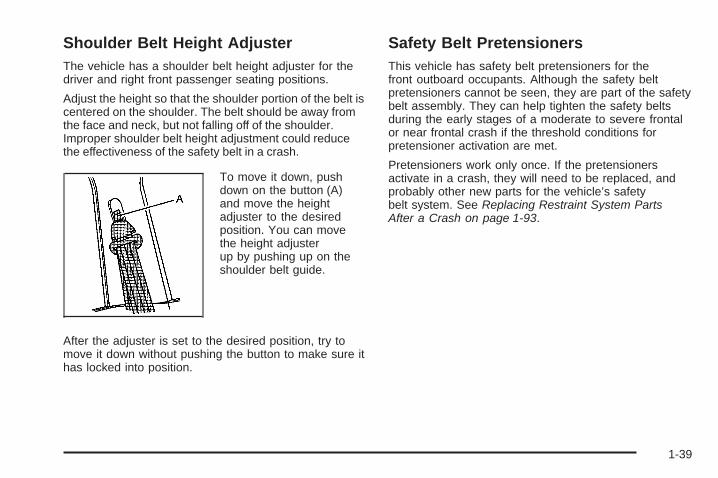
Shoulder Belt Height AdjusterThe vehicle has a shoulder belt height adjuster for thedriver and right front passenger seating positions.
Adjust the height so that the shoulder portion of the belt iscentered on the shoulder. The belt should be away fromthe face and neck, but not falling off of the shoulder.Improper shoulder belt height adjustment could reducethe effectiveness of the safety belt in a crash.
To move it down, pushdown on the button (A)and move the heightadjuster to the desiredposition. You can movethe height adjusterup by pushing up on theshoulder belt guide.
After the adjuster is set to the desired position, try tomove it down without pushing the button to make sure ithas locked into position.
Safety Belt PretensionersThis vehicle has safety belt pretensioners for thefront outboard occupants. Although the safety beltpretensioners cannot be seen, they are part of the safetybelt assembly. They can help tighten the safety beltsduring the early stages of a moderate to severe frontalor near frontal crash if the threshold conditions forpretensioner activation are met.
Pretensioners work only once. If the pretensionersactivate in a crash, they will need to be replaced, andprobably other new parts for the vehicle’s safetybelt system. See Replacing Restraint System PartsAfter a Crash on page 1-93.
1-39
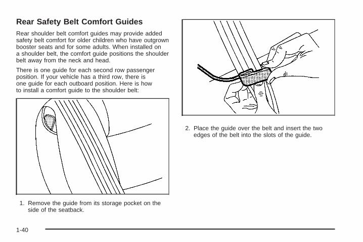
Rear Safety Belt Comfort GuidesRear shoulder belt comfort guides may provide addedsafety belt comfort for older children who have outgrownbooster seats and for some adults. When installed ona shoulder belt, the comfort guide positions the shoulderbelt away from the neck and head.
There is one guide for each second row passengerposition. If your vehicle has a third row, there isone guide for each outboard position. Here is howto install a comfort guide to the shoulder belt:
1. Remove the guide from its storage pocket on theside of the seatback.
2. Place the guide over the belt and insert the twoedges of the belt into the slots of the guide.
1-40

3. Be sure that the belt is not twisted and it lies flat.The elastic cord must be under the belt and theguide on top.
{CAUTION:
A safety belt that is not properly worn may notprovide the protection needed in a crash. Theperson wearing the belt could be seriously injured.The shoulder belt should go over the shoulder andacross the chest. These parts of the body are bestable to take belt restraining forces.
4. Buckle, position, and release the safety belt asdescribed in previously in this section. Makesure that the shoulder belt crosses the shoulder.
To remove and store the comfort guide, squeeze thebelt edges together so that the safety belt can beremoved from the guide. Slide the guide into the storagepocket.
1-41
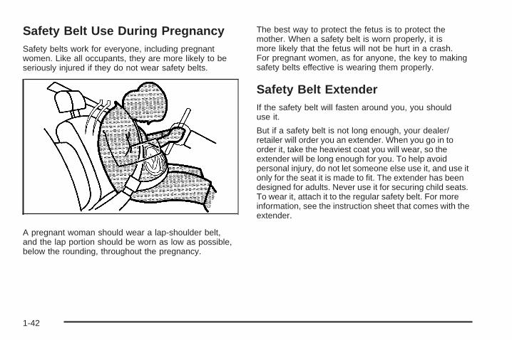
Safety Belt Use During PregnancySafety belts work for everyone, including pregnantwomen. Like all occupants, they are more likely to beseriously injured if they do not wear safety belts.
A pregnant woman should wear a lap-shoulder belt,and the lap portion should be worn as low as possible,below the rounding, throughout the pregnancy.
The best way to protect the fetus is to protect themother. When a safety belt is worn properly, it ismore likely that the fetus will not be hurt in a crash.For pregnant women, as for anyone, the key to makingsafety belts effective is wearing them properly.
Safety Belt ExtenderIf the safety belt will fasten around you, you shoulduse it.
But if a safety belt is not long enough, your dealer/retailer will order you an extender. When you go in toorder it, take the heaviest coat you will wear, so theextender will be long enough for you. To help avoidpersonal injury, do not let someone else use it, and use itonly for the seat it is made to fit. The extender has beendesigned for adults. Never use it for securing child seats.To wear it, attach it to the regular safety belt. For moreinformation, see the instruction sheet that comes with theextender.
1-42
Child Restraints
Older Children
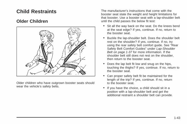
Older children who have outgrown booster seats shouldwear the vehicle’s safety belts.
The manufacturer’s instructions that come with thebooster seat state the weight and height limitations forthat booster. Use a booster seat with a lap-shoulder beltuntil the child passes the below fit test:
• Sit all the way back on the seat. Do the knees bendat the seat edge? If yes, continue. If no, return tothe booster seat.
• Buckle the lap-shoulder belt. Does the shoulder beltrest on the shoulder? If yes, continue. If no, tryusing the rear safety belt comfort guide. See “RearSafety Belt Comfort Guides” under Lap-ShoulderBelt on page 1-37 for more information. If theshoulder belt still does not rest on the shoulder,then return to the booster seat.
• Does the lap belt fit low and snug on the hips,touching the thighs? If yes, continue. If no, return tothe booster seat.
• Can proper safety belt fit be maintained for thelength of the trip? If yes, continue. If no, returnto the booster seat.
• If you have the choice, a child should sit in aposition with a lap-shoulder belt and get theadditional restraint a shoulder belt can provide.
1-43
Q: What is the proper way to wear safety belts?
A: An older child should wear a lap-shoulder belt andget the additional restraint a shoulder belt canprovide. The shoulder belt should not cross the faceor neck. The lap belt should fit snugly below thehips, just touching the top of the thighs. This appliesbelt force to the child’s pelvic bones in a crash. Itshould never be worn over the abdomen, whichcould cause severe or even fatal internal injuries ina crash.
Also see “Rear Safety Belt Comfort Guides” underLap-Shoulder Belt on page 1-37.
According to accident statistics, children and infants aresafer when properly restrained in a child restraintsystem or infant restraint system secured in a rearseating position.
In a crash, children who are not buckled up can strikeother people who are buckled up, or can be thrownout of the vehicle. Older children need to use safetybelts properly.
{CAUTION:
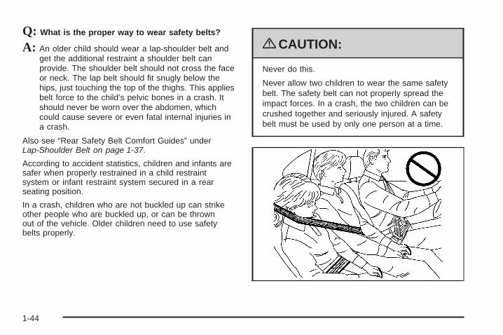
Never do this.
Never allow two children to wear the same safetybelt. The safety belt can not properly spread theimpact forces. In a crash, the two children can becrushed together and seriously injured. A safetybelt must be used by only one person at a time.
1-44
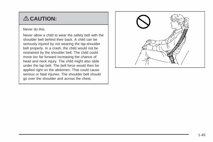
{CAUTION:
Never do this.
Never allow a child to wear the safety belt with theshoulder belt behind their back. A child can beseriously injured by not wearing the lap-shoulderbelt properly. In a crash, the child would not berestrained by the shoulder belt. The child couldmove too far forward increasing the chance ofhead and neck injury. The child might also slideunder the lap belt. The belt force would then beapplied right on the abdomen. That could causeserious or fatal injuries. The shoulder belt shouldgo over the shoulder and across the chest.
1-45
Infants and Young ChildrenEveryone in a vehicle needs protection! This includesinfants and all other children. Neither the distancetraveled nor the age and size of the traveler changesthe need, for everyone, to use safety restraints. In fact,the law in every state in the United States and in everyCanadian province says children up to some age must berestrained while in a vehicle.
{CAUTION:
Children can be seriously injured or strangled if ashoulder belt is wrapped around their neck andthe safety belt continues to tighten. Never leavechildren unattended in a vehicle and never allowchildren to play with the safety belts.
Airbags plus lap-shoulder belts offer protection for adultsand older children, but not for young children and infants.Neither the vehicle’s safety belt system nor its airbagsystem is designed for them. Every time infants and
young children ride in vehicles, they should have theprotection provided by appropriate child restraints. Everytime infants and young children ride in vehicles, theyshould have the protection provided by appropriate childrestraints.
Children who are not restrained properly can strikeother people, or can be thrown out of the vehicle.
{CAUTION:
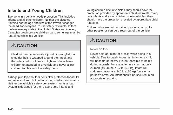
Never do this.
Never hold an infant or a child while riding in avehicle. Due to crash forces, an infant or a childwill become so heavy it is not possible to hold itduring a crash. For example, in a crash at only25 mph (40 km/h), a 12 lb (5.5 kg) infant willsuddenly become a 240 lb (110 kg) force on aperson’s arms. An infant should be secured in anappropriate restraint.
1-46
{CAUTION:
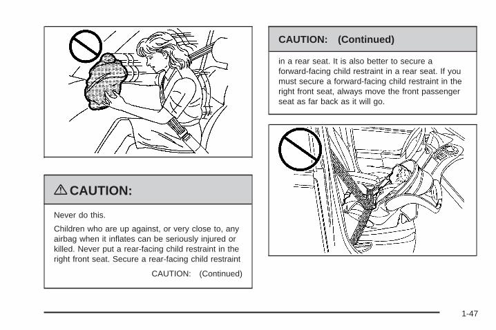
Never do this.
Children who are up against, or very close to, anyairbag when it inflates can be seriously injured orkilled. Never put a rear-facing child restraint in theright front seat. Secure a rear-facing child restraint
CAUTION: (Continued)
CAUTION: (Continued)
in a rear seat. It is also better to secure aforward-facing child restraint in a rear seat. If youmust secure a forward-facing child restraint in theright front seat, always move the front passengerseat as far back as it will go.
1-47
Q: What are the different types of add-on childrestraints?
A: Add-on child restraints, which are purchased by thevehicle’s owner, are available in four basic types.Selection of a particular restraint should takeinto consideration not only the child’s weight, height,and age but also whether or not the restraint willbe compatible with the motor vehicle in which it willbe used.
For most basic types of child restraints, there aremany different models available. When purchasing achild restraint, be sure it is designed to be usedin a motor vehicle. If it is, the restraint will have alabel saying that it meets federal motor vehiclesafety standards.
The restraint manufacturer’s instructions that comewith the restraint state the weight and heightlimitations for a particular child restraint. In addition,there are many kinds of restraints available forchildren with special needs.
{CAUTION:
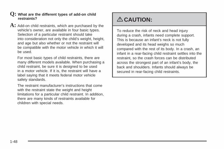
To reduce the risk of neck and head injuryduring a crash, infants need complete support.This is because an infant’s neck is not fullydeveloped and its head weighs so muchcompared with the rest of its body. In a crash, aninfant in a rear-facing child restraint settles into therestraint, so the crash forces can be distributedacross the strongest part of an infant’s body, theback and shoulders. Infants should always besecured in rear-facing child restraints.
1-48
{CAUTION:
A young child’s hip bones are still so small thatthe vehicle’s regular safety belt may not remainlow on the hip bones, as it should. Instead, it maysettle up around the child’s abdomen. In a crash,the belt would apply force on a body area that isunprotected by any bony structure. This alonecould cause serious or fatal injuries. To reducethe risk of serious or fatal injuries during a crash,young children should always be secured inappropriate child restraints.
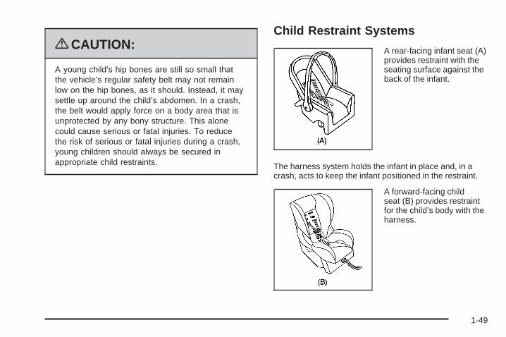
Child Restraint Systems
A rear-facing infant seat (A)provides restraint with theseating surface against theback of the infant.
The harness system holds the infant in place and, in acrash, acts to keep the infant positioned in the restraint.
A forward-facing childseat (B) provides restraintfor the child’s body with theharness.
1-49
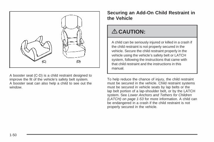
A booster seat (C-D) is a child restraint designed toimprove the fit of the vehicle’s safety belt system.A booster seat can also help a child to see out thewindow.
Securing an Add-On Child Restraint inthe Vehicle
{CAUTION:
A child can be seriously injured or killed in a crash ifthe child restraint is not properly secured in thevehicle. Secure the child restraint properly in thevehicle using the vehicle’s safety belt or LATCHsystem, following the instructions that came withthat child restraint and the instructions in thismanual.
To help reduce the chance of injury, the child restraintmust be secured in the vehicle. Child restraint systemsmust be secured in vehicle seats by lap belts or thelap belt portion of a lap-shoulder belt, or by the LATCHsystem. See Lower Anchors and Tethers for Children(LATCH) on page 1-53 for more information. A child canbe endangered in a crash if the child restraint is notproperly secured in the vehicle.
1-50
When securing an add-on child restraint, refer to theinstructions that come with the restraint which may be onthe restraint itself or in a booklet, or both, and to thismanual. The child restraint instructions are important,so if they are not available, obtain a replacementcopy from the manufacturer.
Keep in mind that an unsecured child restraint canmove around in a collision or sudden stop and injurepeople in the vehicle. Be sure to properly secureany child restraint in the vehicle — even when no childis in it.
Securing the Child Within the ChildRestraint
{CAUTION:
A child can be seriously injured or killed in a crashif the child is not properly secured in the childrestraint. Secure the child properly following theinstructions that came with that child restraint.
Where to Put the RestraintAccording to accident statistics, children and infants aresafer when properly restrained in a child restraintsystem or infant restraint system secured in a rearseating position.
We recommend that children and child restraints besecured in a rear seat, including: an infant or achild riding in a rear-facing child restraint; a child ridingin a forward-facing child seat; an older child riding ina booster seat; and children, who are large enough,using safety belts.
1-51
A label on the sun visor says, “Never put a rear-facingchild restraint in the front.” This is because the riskto the rear-facing child is so great, if the airbag deploys.
{CAUTION:
A child in a rear-facing child restraint can beseriously injured or killed if the right frontpassenger airbag inflates. This is because theback of the rear-facing child restraint would bevery close to the inflating airbag. A child in aforward-facing child restraint can be seriouslyinjured or killed if the right front passenger airbaginflates and the passenger seat is in a forwardposition.
Even if the passenger sensing system has turnedoff the right front passenger frontal airbag, nosystem is fail-safe. No one can guarantee thatan airbag will not deploy under some unusualcircumstance, even though it is turned off.
CAUTION: (Continued)
CAUTION: (Continued)
Secure rear-facing child restraints in a rearseat, even if the airbag is off. If you secure aforward-facing child restraint in the right front seat,always move the front passenger seat as far backas it will go. It is better to secure the child restraintin a rear seat.
See Passenger Sensing System on page 1-85 foradditional information.
When securing a child restraint in a rear seating position,study the instructions that came with the child restraint tomake sure it is compatible with this vehicle.
Wherever a child restraint is installed, be sure to securethe child restraint properly.
Keep in mind that an unsecured child restraint canmove around in a collision or sudden stop and injurepeople in the vehicle. Be sure to properly secureany child restraint in the vehicle — even when no childis in it.
1-52

Lower Anchors and Tethers forChildren (LATCH)The LATCH system holds a child restraint during drivingor in a crash. This system is designed to make installationof a child restraint easier. The LATCH system usesanchors in the vehicle and attachments on the childrestraint that are made for use with the LATCH system.
Make sure that a LATCH-compatible child restraint isproperly installed using the anchors, or use the vehicle’ssafety belts to secure the restraint, following theinstructions that came with that restraint, and also theinstructions in this manual. When installing a childrestraint with a top tether, you must also use either thelower anchors or the safety belts to properly securethe child restraint. A child restraint must never beinstalled using only the top tether and anchor.
In order to use the LATCH system in your vehicle, youneed a child restraint that has LATCH attachments.The child restraint manufacturer will provide youwith instructions on how to use the child restraint and itsattachments. The following explains how to attach achild restraint with these attachments in your vehicle.
Not all vehicle seating positions or child restraints havelower anchors and attachments or top tether anchorsand attachments.
Lower Anchors
Lower anchors (A) are metal bars built into the vehicle.There are two lower anchors for each LATCH seatingposition that will accommodate a child restraint withlower attachments (B).
1-53
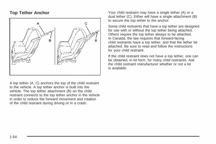
Top Tether Anchor
A top tether (A, C) anchors the top of the child restraintto the vehicle. A top tether anchor is built into thevehicle. The top tether attachment (B) on the childrestraint connects to the top tether anchor in the vehiclein order to reduce the forward movement and rotationof the child restraint during driving or in a crash.
Your child restraint may have a single tether (A) or adual tether (C). Either will have a single attachment (B)to secure the top tether to the anchor.
Some child restraints that have a top tether are designedfor use with or without the top tether being attached.Others require the top tether always to be attached.In Canada, the law requires that forward-facingchild restraints have a top tether, and that the tether beattached. Be sure to read and follow the instructionsfor your child restraint.
If the child restraint does not have a top tether, one canbe obtained, in kit form, for many child restraints. Askthe child restraint manufacturer whether or not a kitis available.
1-54
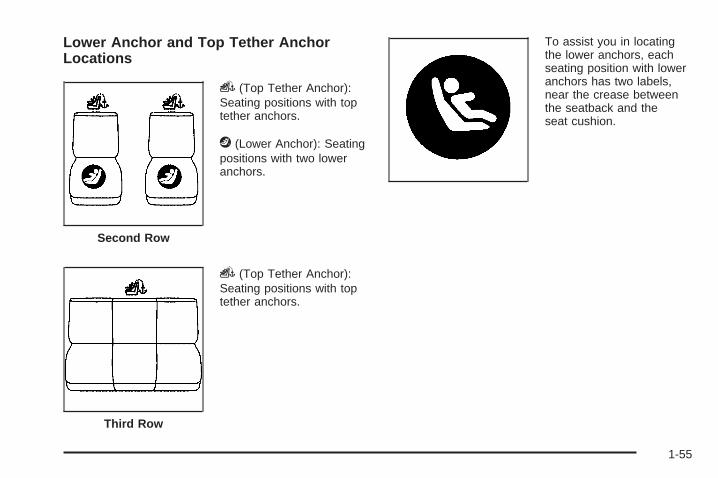
Lower Anchor and Top Tether AnchorLocations
i (Top Tether Anchor):Seating positions with toptether anchors.
j (Lower Anchor): Seatingpositions with two loweranchors.
i (Top Tether Anchor):Seating positions with toptether anchors.
To assist you in locatingthe lower anchors, eachseating position with loweranchors has two labels,near the crease betweenthe seatback and theseat cushion.
Second Row
Third Row
1-55
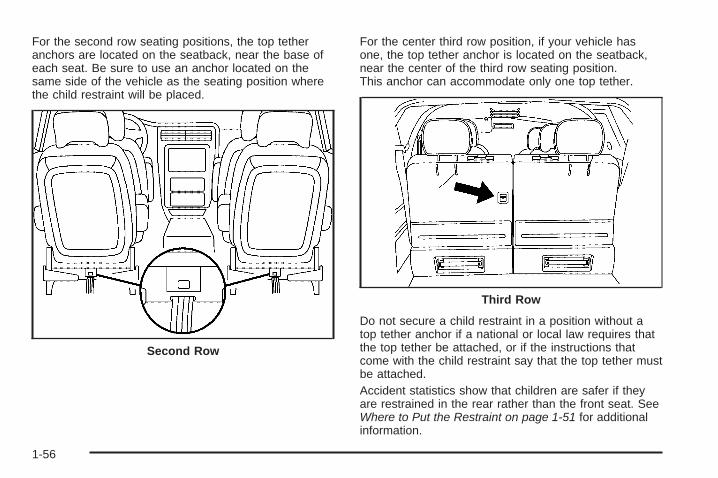
For the second row seating positions, the top tetheranchors are located on the seatback, near the base ofeach seat. Be sure to use an anchor located on thesame side of the vehicle as the seating position wherethe child restraint will be placed.
For the center third row position, if your vehicle hasone, the top tether anchor is located on the seatback,near the center of the third row seating position.This anchor can accommodate only one top tether.
Do not secure a child restraint in a position without atop tether anchor if a national or local law requires thatthe top tether be attached, or if the instructions thatcome with the child restraint say that the top tether mustbe attached.Accident statistics show that children are safer if theyare restrained in the rear rather than the front seat. SeeWhere to Put the Restraint on page 1-51 for additionalinformation.
Second Row
Third Row
1-56
Securing a Child Restraint Designed forthe LATCH System
{CAUTION:
If a LATCH-type child restraint is not attached toanchors, the child restraint will not be able toprotect the child correctly. In a crash, the childcould be seriously injured or killed. Install aLATCH-type child restraint properly using theanchors, or use the vehicle’s safety belts to securethe restraint, following the instructions that camewith the child restraint and the instructions in thismanual.
{CAUTION:
Do not attach more than one child restraint to asingle anchor. Attaching more than one childrestraint to a single anchor could cause the anchoror attachment to come loose or even break during acrash. A child or others could be injured. To reducethe risk of serious or fatal injuries during a crash,attach only one child restraint per anchor.
1-57
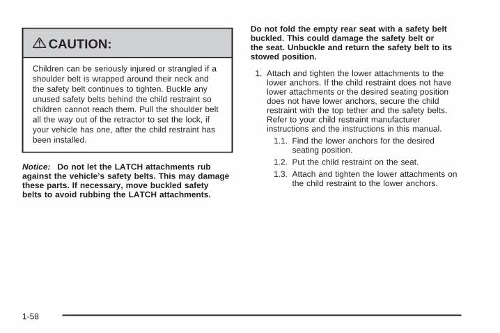
{CAUTION:
Children can be seriously injured or strangled if ashoulder belt is wrapped around their neck andthe safety belt continues to tighten. Buckle anyunused safety belts behind the child restraint sochildren cannot reach them. Pull the shoulder beltall the way out of the retractor to set the lock, ifyour vehicle has one, after the child restraint hasbeen installed.
Notice: Do not let the LATCH attachments rubagainst the vehicle’s safety belts. This may damagethese parts. If necessary, move buckled safetybelts to avoid rubbing the LATCH attachments.
Do not fold the empty rear seat with a safety beltbuckled. This could damage the safety belt orthe seat. Unbuckle and return the safety belt to itsstowed position.
1. Attach and tighten the lower attachments to thelower anchors. If the child restraint does not havelower attachments or the desired seating positiondoes not have lower anchors, secure the childrestraint with the top tether and the safety belts.Refer to your child restraint manufacturerinstructions and the instructions in this manual.
1.1. Find the lower anchors for the desiredseating position.
1.2. Put the child restraint on the seat.1.3. Attach and tighten the lower attachments on
the child restraint to the lower anchors.
1-58
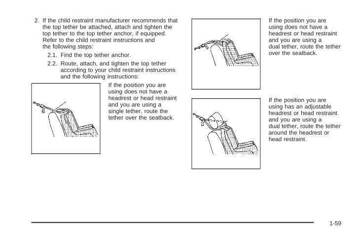
2. If the child restraint manufacturer recommends thatthe top tether be attached, attach and tighten thetop tether to the top tether anchor, if equipped.Refer to the child restraint instructions andthe following steps:
2.1. Find the top tether anchor.2.2. Route, attach, and tighten the top tether
according to your child restraint instructionsand the following instructions:
If the position you areusing does not have aheadrest or head restraintand you are using asingle tether, route thetether over the seatback.
If the position you areusing does not have aheadrest or head restraintand you are using adual tether, route the tetherover the seatback.
If the position you areusing has an adjustableheadrest or head restraintand you are using adual tether, route the tetheraround the headrest orhead restraint.
1-59
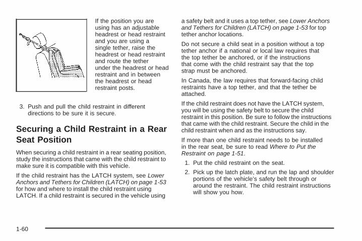
If the position you areusing has an adjustableheadrest or head restraintand you are using asingle tether, raise theheadrest or head restraintand route the tetherunder the headrest or headrestraint and in betweenthe headrest or headrestraint posts.
3. Push and pull the child restraint in differentdirections to be sure it is secure.
Securing a Child Restraint in a RearSeat PositionWhen securing a child restraint in a rear seating position,study the instructions that came with the child restraint tomake sure it is compatible with this vehicle.
If the child restraint has the LATCH system, see LowerAnchors and Tethers for Children (LATCH) on page 1-53for how and where to install the child restraint usingLATCH. If a child restraint is secured in the vehicle using
a safety belt and it uses a top tether, see Lower Anchorsand Tethers for Children (LATCH) on page 1-53 for toptether anchor locations.
Do not secure a child seat in a position without a toptether anchor if a national or local law requires thatthe top tether be anchored, or if the instructionsthat come with the child restraint say that the topstrap must be anchored.
In Canada, the law requires that forward-facing childrestraints have a top tether, and that the tether beattached.
If the child restraint does not have the LATCH system,you will be using the safety belt to secure the childrestraint in this position. Be sure to follow the instructionsthat came with the child restraint. Secure the child in thechild restraint when and as the instructions say.
If more than one child restraint needs to be installedin the rear seat, be sure to read Where to Put theRestraint on page 1-51.
1. Put the child restraint on the seat.
2. Pick up the latch plate, and run the lap and shoulderportions of the vehicle’s safety belt through oraround the restraint. The child restraint instructionswill show you how.
1-60

3. Push the latch plate into the buckle until it clicks.Position the release button on the buckle so thatthe safety belt could be quickly unbuckled ifnecessary.
4. Pull the rest of the shoulder belt all the way out ofthe retractor to set the lock.
1-61
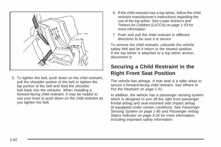
5. To tighten the belt, push down on the child restraint,pull the shoulder portion of the belt to tighten thelap portion of the belt and feed the shoulderbelt back into the retractor. When installing aforward-facing child restraint, it may be helpful touse your knee to push down on the child restraint asyou tighten the belt.
6. If the child restraint has a top tether, follow the childrestraint manufacturer’s instructions regarding theuse of the top tether. See Lower Anchors andTethers for Children (LATCH) on page 1-53 formore information.
7. Push and pull the child restraint in differentdirections to be sure it is secure.
To remove the child restraint, unbuckle the vehiclesafety belt and let it return to the stowed position.If the top tether is attached to a top tether anchor,disconnect it.
Securing a Child Restraint in theRight Front Seat PositionThe vehicle has airbags. A rear seat is a safer place tosecure a forward-facing child restraint. See Where toPut the Restraint on page 1-51.
In addition, the vehicle has a passenger sensing systemwhich is designed to turn off the right front passengerfrontal airbag and seat-mounted side impact airbag(if equipped) under certain conditions. See PassengerSensing System on page 1-85 and Passenger AirbagStatus Indicator on page 3-34 for more information,including important safety information.
1-62
A label on the sun visor says, “Never put a rear-facingchild seat in the front.” This is because the risk tothe rear-facing child is so great, if the airbag deploys.
{CAUTION:
A child in a rear-facing child restraint can beseriously injured or killed if the right frontpassenger airbag inflates. This is because theback of the rear-facing child restraint would bevery close to the inflating airbag. A child in aforward-facing child restraint can be seriouslyinjured or killed if the right front passenger airbaginflates and the passenger seat is in a forwardposition.
CAUTION: (Continued)
CAUTION: (Continued)
Even if the passenger sensing system has turnedoff the right front passenger frontal airbag, nosystem is fail-safe. No one can guarantee thatan airbag will not deploy under some unusualcircumstance, even though it is turned off.
Secure rear-facing child restraints in a rearseat, even if the airbag is off. If you secure aforward-facing child restraint in the right front seat,always move the front passenger seat as far backas it will go. It is better to secure the child restraintin a rear seat.
See Passenger Sensing System on page 1-85 foradditional information.
If the vehicle does not have a rear seat that willaccommodate a rear-facing child restraint, a rear-facingchild restraint should not be installed in the vehicle,even if the airbag is off.
1-63
If the child restraint has the LATCH system, seeLower Anchors and Tethers for Children (LATCH) onpage 1-53 for how and where to install the child restraintusing LATCH. If a child restraint is secured using asafety belt and it uses a top tether, see Lower Anchorsand Tethers for Children (LATCH) on page 1-53 fortop tether anchor locations.
Do not secure a child seat in a position without a toptether anchor if a national or local law requires that thetop tether be anchored, or if the instructions that comewith the child restraint say that the top strap must beanchored.
In Canada, the law requires that forward-facing childrestraints have a top tether, and that the tether beattached.
You will be using the lap-shoulder belt to secure thechild restraint in this position. Follow the instructions thatcame with the child restraint.
1. Move the seat as far back as it will go beforesecuring the forward-facing child restraint.When the passenger sensing system has turnedoff the right front passenger frontal airbag andseat-mounted side impact airbag (if equipped), theoff indicator on the passenger airbag status indicatorshould light and stay lit when the vehicle is started.See Passenger Airbag Status Indicator onpage 3-34.
2. Put the child restraint on the seat.
3. Pick up the latch plate, and run the lap and shoulderportions of the vehicle’s safety belt through or aroundthe restraint. The child restraint instructions will showyou how.
1-64
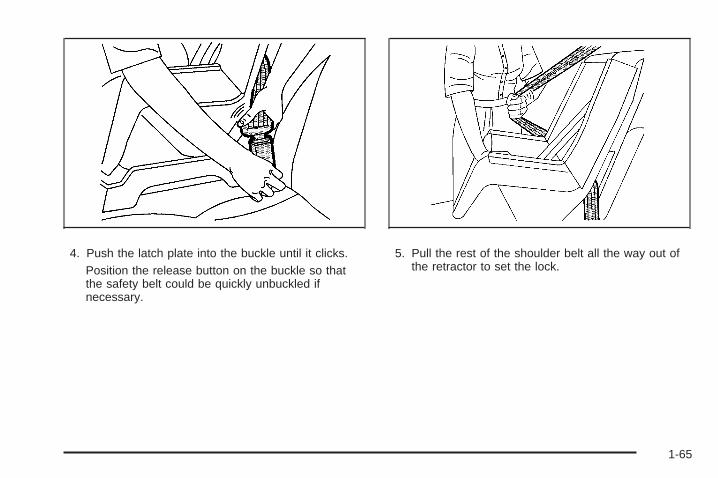
4. Push the latch plate into the buckle until it clicks.Position the release button on the buckle so thatthe safety belt could be quickly unbuckled ifnecessary.
5. Pull the rest of the shoulder belt all the way out ofthe retractor to set the lock.
1-65
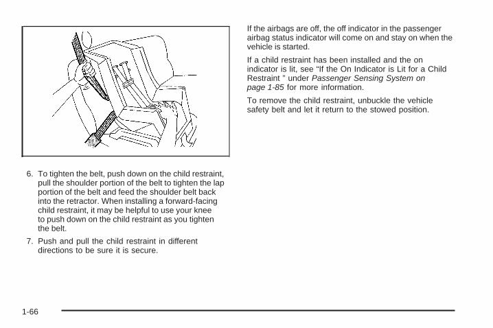
6. To tighten the belt, push down on the child restraint,pull the shoulder portion of the belt to tighten the lapportion of the belt and feed the shoulder belt backinto the retractor. When installing a forward-facingchild restraint, it may be helpful to use your kneeto push down on the child restraint as you tightenthe belt.
7. Push and pull the child restraint in differentdirections to be sure it is secure.
If the airbags are off, the off indicator in the passengerairbag status indicator will come on and stay on when thevehicle is started.
If a child restraint has been installed and the onindicator is lit, see “If the On Indicator is Lit for a ChildRestraint ” under Passenger Sensing System onpage 1-85 for more information.
To remove the child restraint, unbuckle the vehiclesafety belt and let it return to the stowed position.
1-66
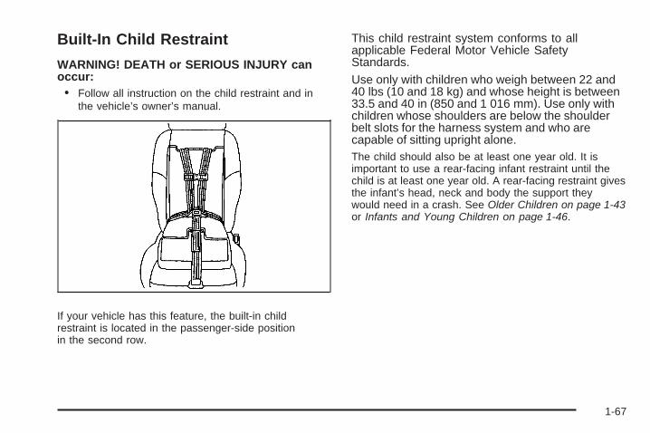
Built-In Child Restraint
WARNING! DEATH or SERIOUS INJURY canoccur:• Follow all instruction on the child restraint and in
the vehicle’s owner’s manual.
If your vehicle has this feature, the built-in childrestraint is located in the passenger-side positionin the second row.
This child restraint system conforms to allapplicable Federal Motor Vehicle SafetyStandards.
Use only with children who weigh between 22 and40 lbs (10 and 18 kg) and whose height is between33.5 and 40 in (850 and 1 016 mm). Use only withchildren whose shoulders are below the shoulderbelt slots for the harness system and who arecapable of sitting upright alone.The child should also be at least one year old. It isimportant to use a rear-facing infant restraint until thechild is at least one year old. A rear-facing restraint givesthe infant’s head, neck and body the support theywould need in a crash. See Older Children on page 1-43or Infants and Young Children on page 1-46.
1-67
A child whose weight is over 40 lbs (18 kg), whoseheight is over 40 in (1 016 mm) or whose shoulders areabove the shoulder belt slots for the harness system,should be restrained in an add-on booster seatappropriate for the child’s size. See Child RestraintSystems on page 1-49. Once the booster seat isoutgrown, the child should sit on the vehicle’s regularseat and use the vehicle’s safety belts.
{CAUTION:
Using the vehicle’s built-in child restraint as abooster seat for a larger child could cause injury tothe child in a sudden stop or crash. A child whoseweight is over 40 lbs (18 kg), whose height is over40 in (1 016 mm) or whose shoulders are abovethe shoulder belt slots for the harness systemshould use a restraint system that is appropriatefor their size, either an add-on booster seat or thevehicle’s safety belt. See Child Restraint Systemson page 1-49 or Older Children on page 1-43.
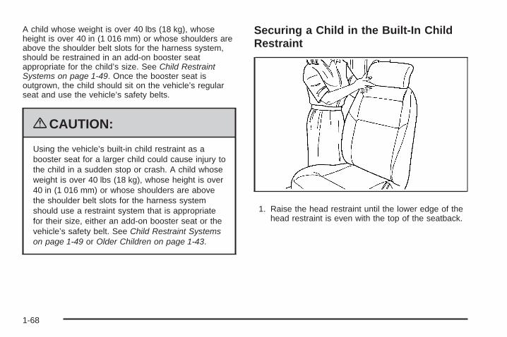
Securing a Child in the Built-In ChildRestraint
1. Raise the head restraint until the lower edge of thehead restraint is even with the top of the seatback.
1-68
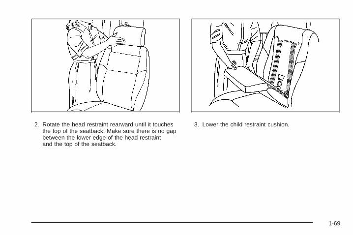
2. Rotate the head restraint rearward until it touchesthe top of the seatback. Make sure there is no gapbetween the lower edge of the head restraintand the top of the seatback.
3. Lower the child restraint cushion.
1-69
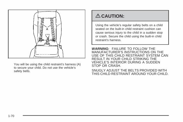
You will be using the child restraint’s harness (A)to secure your child. Do not use the vehicle’ssafety belts.
{CAUTION:
Using the vehicle’s regular safety belts on a childseated on the built-in child restraint cushion cancause serious injury to the child in a sudden stopor crash. Secure the child using the built-in childrestraint’s harness.
WARNING: FAILURE TO FOLLOW THEMANUFACTURER’S INSTRUCTIONS ON THEUSE OF THIS CHILD RESTRAINT SYSTEM CANRESULT IN YOUR CHILD STRIKING THEVEHICLE’S INTERIOR DURING A SUDDENSTOP OR CRASH.SNUGLY ADJUST THE BELTS PROVIDED WITHTHIS CHILD RESTRAINT AROUND YOUR CHILD.
1-70
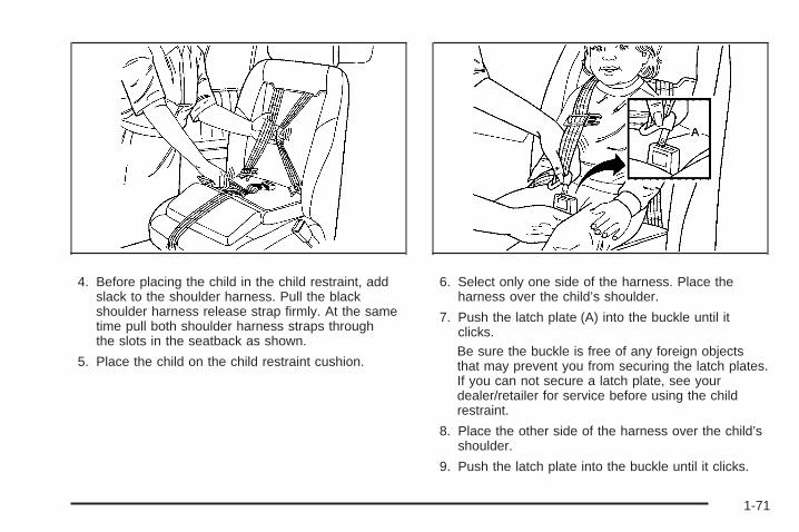
4. Before placing the child in the child restraint, addslack to the shoulder harness. Pull the blackshoulder harness release strap firmly. At the sametime pull both shoulder harness straps throughthe slots in the seatback as shown.
5. Place the child on the child restraint cushion.
6. Select only one side of the harness. Place theharness over the child’s shoulder.
7. Push the latch plate (A) into the buckle until itclicks.Be sure the buckle is free of any foreign objectsthat may prevent you from securing the latch plates.If you can not secure a latch plate, see yourdealer/retailer for service before using the childrestraint.
8. Place the other side of the harness over the child’sshoulder.
9. Push the latch plate into the buckle until it clicks.
1-71
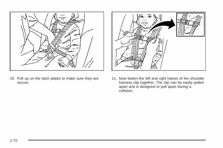
10. Pull up on the latch plates to make sure they aresecure.
11. Now fasten the left and right halves of the shoulderharness clip together. The clip can be easily pulledapart and is designed to pull apart during acollision.
1-72
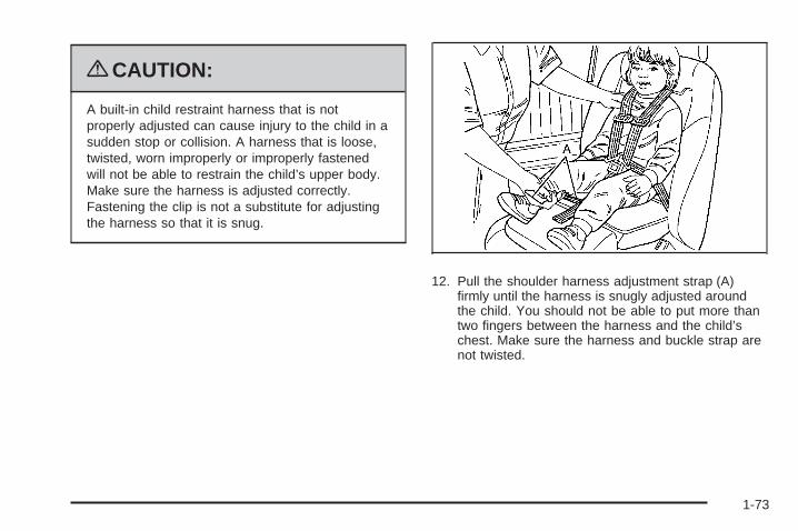
{CAUTION:
A built-in child restraint harness that is notproperly adjusted can cause injury to the child in asudden stop or collision. A harness that is loose,twisted, worn improperly or improperly fastenedwill not be able to restrain the child’s upper body.Make sure the harness is adjusted correctly.Fastening the clip is not a substitute for adjustingthe harness so that it is snug.
12. Pull the shoulder harness adjustment strap (A)firmly until the harness is snugly adjusted aroundthe child. You should not be able to put more thantwo fingers between the harness and the child’schest. Make sure the harness and buckle strap arenot twisted.
1-73
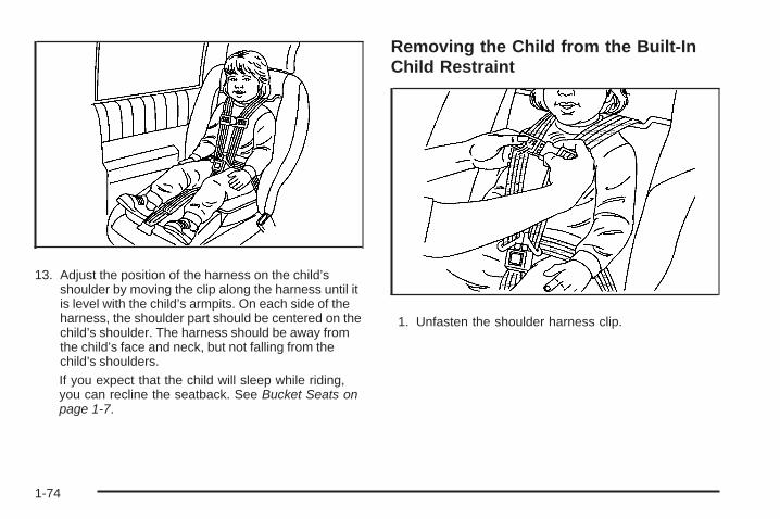
13. Adjust the position of the harness on the child’sshoulder by moving the clip along the harness until itis level with the child’s armpits. On each side of theharness, the shoulder part should be centered on thechild’s shoulder. The harness should be away fromthe child’s face and neck, but not falling from thechild’s shoulders.If you expect that the child will sleep while riding,you can recline the seatback. See Bucket Seats onpage 1-7.
Removing the Child from the Built-InChild Restraint
1. Unfasten the shoulder harness clip.
1-74
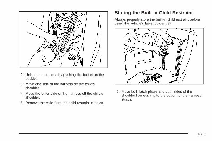
2. Unlatch the harness by pushing the button on thebuckle.
3. Move one side of the harness off the child’sshoulder.
4. Move the other side of the harness off the child’sshoulder.
5. Remove the child from the child restraint cushion.
Storing the Built-In Child RestraintAlways properly store the built-in child restraint beforeusing the vehicle’s lap-shoulder belt.
1. Move both latch plates and both sides of theshoulder harness clip to the bottom of the harnessstraps.
1-75
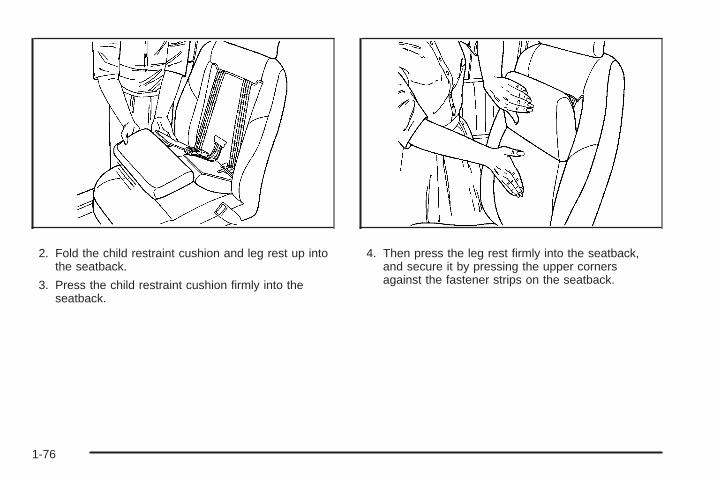
2. Fold the child restraint cushion and leg rest up intothe seatback.
3. Press the child restraint cushion firmly into theseatback.
4. Then press the leg rest firmly into the seatback,and secure it by pressing the upper cornersagainst the fastener strips on the seatback.
1-76
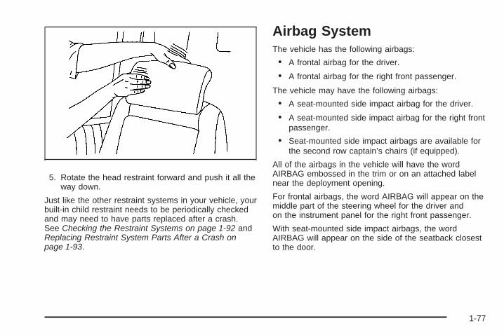
5. Rotate the head restraint forward and push it all theway down.
Just like the other restraint systems in your vehicle, yourbuilt-in child restraint needs to be periodically checkedand may need to have parts replaced after a crash.See Checking the Restraint Systems on page 1-92 andReplacing Restraint System Parts After a Crash onpage 1-93.
Airbag SystemThe vehicle has the following airbags:
• A frontal airbag for the driver.
• A frontal airbag for the right front passenger.
The vehicle may have the following airbags:
• A seat-mounted side impact airbag for the driver.
• A seat-mounted side impact airbag for the right frontpassenger.
• Seat-mounted side impact airbags are available forthe second row captain’s chairs (if equipped).
All of the airbags in the vehicle will have the wordAIRBAG embossed in the trim or on an attached labelnear the deployment opening.
For frontal airbags, the word AIRBAG will appear on themiddle part of the steering wheel for the driver andon the instrument panel for the right front passenger.
With seat-mounted side impact airbags, the wordAIRBAG will appear on the side of the seatback closestto the door.
1-77

Airbags are designed to supplement the protectionprovided by safety belts. Even though today’s airbagsare also designed to help reduce the risk of injuryfrom the force of an inflating bag, all airbags mustinflate very quickly to do their job.
Here are the most important things to know about theairbag system:
{CAUTION:
You can be severely injured or killed in a crash ifyou are not wearing your safety belt — even if youhave airbags. Airbags are designed to work withsafety belts, but do not replace them. Also, airbagsare not designed to deploy in every crash. In somecrashes safety belts are your only restraint. SeeWhen Should an Airbag Inflate? on page 1-82.
Wearing your safety belt during a crash helpsreduce your chance of hitting things inside thevehicle or being ejected from it. Airbags are“supplemental restraints” to the safety belts.Everyone in your vehicle should wear a safety beltproperly — whether or not there is an airbag for thatperson.
{CAUTION:
Airbags inflate with great force, faster than the blinkof an eye. Anyone who is up against, or very closeto, any airbag when it inflates can be seriouslyinjured or killed. Do not sit unnecessarily close tothe airbag, as you would be if you were sitting onthe edge of your seat or leaning forward. Safetybelts help keep you in position before and during acrash. Always wear your safety belt, even withairbags. The driver should sit as far back aspossible while still maintaining control of thevehicle.
Occupants should not lean on or sleep against thedoor or side windows in seating positions withseat-mounted airbags.
1-78

{CAUTION:
Children who are up against, or very close to, anyairbag when it inflates can be seriously injuredor killed. Airbags plus lap-shoulder belts offerprotection for adults and older children, but not foryoung children and infants. Neither the vehicle’ssafety belt system nor its airbag system isdesigned for them. Young children and infantsneed the protection that a child restraint systemcan provide. Always secure children properly inyour vehicle. To read how, see Older Children onpage 1-43 or Infants and Young Children onpage 1-46.
There is an airbagreadiness light on theinstrument panel cluster,which shows the airbagsymbol.
The system checks the airbag electrical system formalfunctions. The light tells you if there is an electricalproblem. See Airbag Readiness Light on page 3-33for more information.
1-79
Where Are the Airbags?
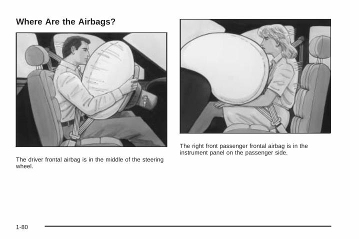
The driver frontal airbag is in the middle of the steeringwheel.
The right front passenger frontal airbag is in theinstrument panel on the passenger side.
1-80
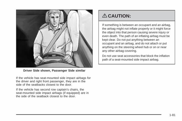
If the vehicle has seat-mounted side impact airbags forthe driver and right front passenger, they are in theside of the seatbacks closest to the door.
If the vehicle has second row captain’s chairs, theseat-mounted side impact airbags (if equipped) are inthe side of the seatback closest to the door.
{CAUTION:
If something is between an occupant and an airbag,the airbag might not inflate properly or it might forcethe object into that person causing severe injury oreven death. The path of an inflating airbag must bekept clear. Do not put anything between anoccupant and an airbag, and do not attach or putanything on the steering wheel hub or on or nearany other airbag covering.
Do not use seat accessories that block the inflationpath of a seat-mounted side impact airbag.
Driver Side shown, Passenger Side similar
1-81
When Should an Airbag Inflate?Frontal airbags are designed to inflate in moderate tosevere frontal or near-frontal crashes to help reduce thepotential for severe injuries mainly to the driver’s orright front passenger’s head and chest. However, theyare only designed to inflate if the impact exceeds apredetermined deployment threshold. Deploymentthresholds are used to predict how severe a crash islikely to be in time for the airbags to inflate andhelp restrain the occupants.
Whether your frontal airbags will or should deploy is notbased on how fast your vehicle is traveling. It dependslargely on what you hit, the direction of the impact,and how quickly your vehicle slows down.
Frontal airbags may inflate at different crash speeds.For example:
• If the vehicle hits a stationary object, the airbagscould inflate at a different crash speed than if thevehicle hits a moving object.
• If the vehicle hits an object that deforms, theairbags could inflate at a different crash speed thanif the vehicle hits an object that does not deform.
• If the vehicle hits a narrow object (like a pole), theairbags could inflate at a different crash speedthan if the vehicle hits a wide object (like a wall).
• If the vehicle goes into an object at an angle, theairbags could inflate at a different crash speedthan if the vehicle goes straight into the object.
Thresholds can also vary with specific vehicle design.
In addition, your vehicle has dual-stage frontal airbags.Dual-stage airbags adjust the restraint according tocrash severity. Your vehicle has electronic frontalsensors, which help the sensing system distinguishbetween a moderate frontal impact and a more severefrontal impact. For moderate frontal impacts, dual-stageairbags inflate at a level less than full deployment.For more severe frontal impacts, full deployment occurs.
Frontal airbags are not intended to inflate duringvehicle rollovers, rear impacts, or in many side impacts.
The vehicle may or may not have seat-mounted sideimpact airbags. See Airbag System on page 1-77.Seat-mounted side impact airbags are intended to inflatein moderate to severe side crashes. Seat-mountedside impact airbags will inflate if the crash severity isabove the system’s designed threshold level. Thethreshold level can vary with specific vehicle design.
1-82
Seat-mounted side impact airbags are not intended toinflate in frontal impacts, near-frontal impacts, rollovers,or rear impacts. A seat-mounted side impact airbagis intended to deploy on the side of the vehicle that isstruck.
In any particular crash, no one can say whether anairbag should have inflated simply because of thedamage to a vehicle or because of what the repair costswere. For frontal airbags, inflation is determined bywhat the vehicle hits, the angle of the impact, and howquickly the vehicle slows down. For seat-mountedside impact airbags, deployment is determined by thelocation and severity of the side impact.
What Makes an Airbag Inflate?In a deployment event, the sensing system sends anelectrical signal triggering a release of gas from theinflator. Gas from the inflator fills the airbag causing thebag to break out of the cover and deploy. The inflator, theairbag, and related hardware are all part of the airbagmodule.
Frontal airbag modules are located inside the steeringwheel and instrument panel. For vehicles withseat-mounted side impact airbags, there are airbagmodules in the side of the front seatbacks closest tothe door.
How Does an Airbag Restrain?In moderate to severe frontal or near frontal collisions,even belted occupants can contact the steering wheelor the instrument panel. In moderate to severe sidecollisions, even belted occupants can contact the insideof the vehicle.
Airbags supplement the protection provided by safetybelts. Frontal airbags distribute the force of theimpact more evenly over the occupant’s upper body,stopping the occupant more gradually. Seat-mountedside impact airbags distribute the force of the impactmore evenly over the occupant’s upper body.
But airbags would not help in many types of collisions,primarily because the occupant’s motion is not towardthose airbags. See When Should an Airbag Inflate? onpage 1-82 for more information.
Airbags should never be regarded as anything morethan a supplement to safety belts.
1-83
What Will You See After an AirbagInflates?After the frontal and seat-mounted side impactairbags inflate, they quickly deflate, so quickly thatsome people may not even realize the airbags inflated.Some components of the airbag module may be hot forseveral minutes. For location of the airbag modules, seeWhat Makes an Airbag Inflate? on page 1-83.
The parts of the airbag that come into contact with youmay be warm, but not too hot to touch. There maybe some smoke and dust coming from the vents in thedeflated airbags. Airbag inflation does not preventthe driver from seeing out of the windshield or beingable to steer the vehicle, nor does it prevent people fromleaving the vehicle.
{CAUTION:
When an airbag inflates, there may be dust in theair. This dust could cause breathing problems forpeople with a history of asthma or other breathingtrouble. To avoid this, everyone in the vehicleshould get out as soon as it is safe to do so. If youhave breathing problems but cannot get out of thevehicle after an airbag inflates, then get fresh air byopening a window or a door. If you experiencebreathing problems following an airbag deployment,you should seek medical attention.
The vehicle has a feature that may automatically unlockthe doors, turn the interior lamps on, and turn on thehazard warning flashers when the airbags inflate. Youcan lock the doors, turn the interior lamps off, and turn thehazard warning flashers off by using the controls forthose features.
1-84
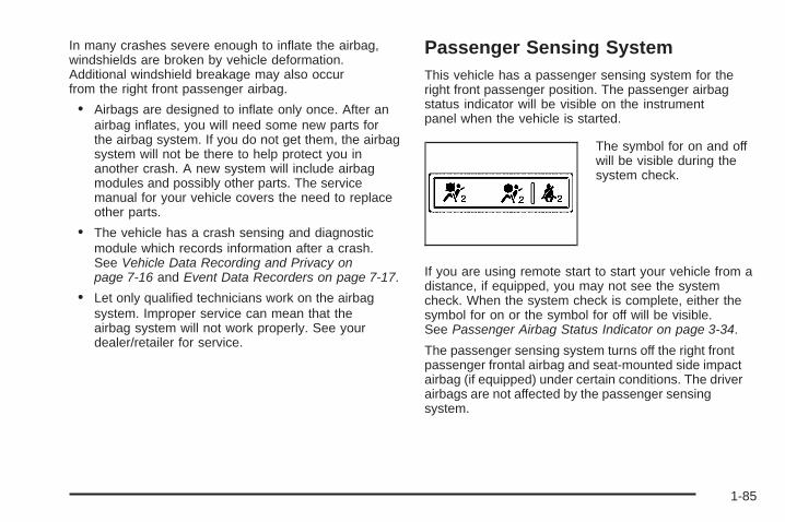
In many crashes severe enough to inflate the airbag,windshields are broken by vehicle deformation.Additional windshield breakage may also occurfrom the right front passenger airbag.
• Airbags are designed to inflate only once. After anairbag inflates, you will need some new parts forthe airbag system. If you do not get them, the airbagsystem will not be there to help protect you inanother crash. A new system will include airbagmodules and possibly other parts. The servicemanual for your vehicle covers the need to replaceother parts.
• The vehicle has a crash sensing and diagnosticmodule which records information after a crash.See Vehicle Data Recording and Privacy onpage 7-16 and Event Data Recorders on page 7-17.
• Let only qualified technicians work on the airbagsystem. Improper service can mean that theairbag system will not work properly. See yourdealer/retailer for service.
Passenger Sensing SystemThis vehicle has a passenger sensing system for theright front passenger position. The passenger airbagstatus indicator will be visible on the instrumentpanel when the vehicle is started.
The symbol for on and offwill be visible during thesystem check.
If you are using remote start to start your vehicle from adistance, if equipped, you may not see the systemcheck. When the system check is complete, either thesymbol for on or the symbol for off will be visible.See Passenger Airbag Status Indicator on page 3-34.
The passenger sensing system turns off the right frontpassenger frontal airbag and seat-mounted side impactairbag (if equipped) under certain conditions. The driverairbags are not affected by the passenger sensingsystem.
1-85
The passenger sensing system works with sensors thatare part of the right front passenger’s seat and safetybelt. The sensors are designed to detect the presence ofa properly-seated occupant and determine if the rightfront passenger frontal airbag and seat-mountedside impact airbag (if equipped) should be enabled(may inflate) or not.
Accident statistics show that children are safer if theyare restrained in the rear rather than the front seat.
We recommend that children be secured in a rear seat,including: an infant or a child riding in a rear-facingchild restraint; a child riding in a forward-facing childseat; an older child riding in a booster seat; and children,who are large enough, using safety belts.
A label on your sun visor says, “Never put a rear-facingchild seat in the front.” This is because the risk to therear-facing child is so great, if the airbag deploys.
{CAUTION:
A child in a rear-facing child restraint can beseriously injured or killed if the right frontpassenger airbag inflates. This is because theback of the rear-facing child restraint would bevery close to the inflating airbag. A child in aforward-facing child restraint can be seriouslyinjured or killed if the right front passenger airbaginflates and the passenger seat is in a forwardposition.
Even if the passenger sensing system has turnedoff the right front passenger frontal airbag andseat-mounted side impact airbag (if equipped),no system is fail-safe. No one can guarantee thatan airbag will not deploy under some unusualcircumstance, even though the airbag(s) are off.
Secure rear-facing child restraints in a rear seat,even if the airbag(s) are off. If you secure aforward-facing child restraint in the right front seat,always move the front passenger seat as far backas it will go. It is better to secure the child restraintin a rear seat.
1-86

If the vehicle does not have a rear seat that willaccommodate a rear-facing child restraint, a rear-facingchild restraint should not be installed in the vehicle,even if the airbag is off.
The passenger sensing system is designed toturn off the right front passenger frontal airbag andseat-mounted side impact airbag (if equipped) if:
• The right front passenger seat is unoccupied.
• The system determines that an infant is present ina rear-facing infant seat.
• The system determines that a small child is presentin a child restraint.
• The system determines that a small child is presentin a booster seat.
• A right front passenger takes his/her weight off ofthe seat for a period of time.
• The right front passenger seat is occupied by asmaller person, such as a child who has outgrownchild restraints.
• Or, if there is a critical problem with the airbagsystem or the passenger sensing system.
When the passenger sensing system has turned off theright front passenger frontal airbag and seat-mountedside impact airbag (if equipped), the off indicator will lightand stay lit to remind you that the airbag(s) are off.See Passenger Airbag Status Indicator on page 3-34.
The passenger sensing system is designed to turn on(may inflate) the right front passenger frontal airbag andseat-mounted side impact airbag (if equipped) anytimethe system senses that a person of adult size is sittingproperly in the right front passenger seat.
When the passenger sensing system has allowed theairbag(s) to be enabled, the on indicator will lightand stay lit to remind you that the airbags are active.
1-87
For some children, including those in child restraints, andfor very small adults, the passenger sensing system mayor may not turn off the right front passenger frontal airbagand seat-mounted side impact airbag (if equipped),depending upon the person’s seating posture and bodybuild. Everyone in your vehicle who has outgrown childrestraints should wear a safety belt properly — whetheror not there is an airbag for that person.
{CAUTION:
If the airbag readiness light in the instrument panelcluster ever comes on and stays on, it means thatsomething may be wrong with the airbag system.If this ever happens, have the vehicle servicedpromptly, because an adult-size person sitting inthe right front passenger’s seat may not have theprotection of the airbag(s). See Airbag ReadinessLight on page 3-33 for more on this, includingimportant safety information.
If the On Indicator is Lit for a ChildRestraintIf a child restraint has been installed and the onindicator is lit:
1. Turn the vehicle off.
2. Remove the child restraint from the vehicle.
3. Remove any additional items from the seat such asblankets, cushions, seat covers, seat heaters, orseat massagers.
4. Reinstall the child restraint following the directionsprovided by the child restraint manufacturer andrefer to Securing a Child Restraint in the Right FrontSeat Position on page 1-62.
5. If, after reinstalling the child restraint and restartingthe vehicle, the on indicator is still lit, turn the vehicleoff. Then slightly recline the vehicle seatback andadjust the seat cushion, if adjustable, to make surethat the vehicle seatback is not pushing the childrestraint into the seat cushion.
6. Restart the vehicle.If the on indicator is still lit, secure the child in thechild restraint in a rear seat position in the vehicle,and check with your dealer/retailer.If no rear seat is available, do not install a childrestraint in this vehicle.
1-88
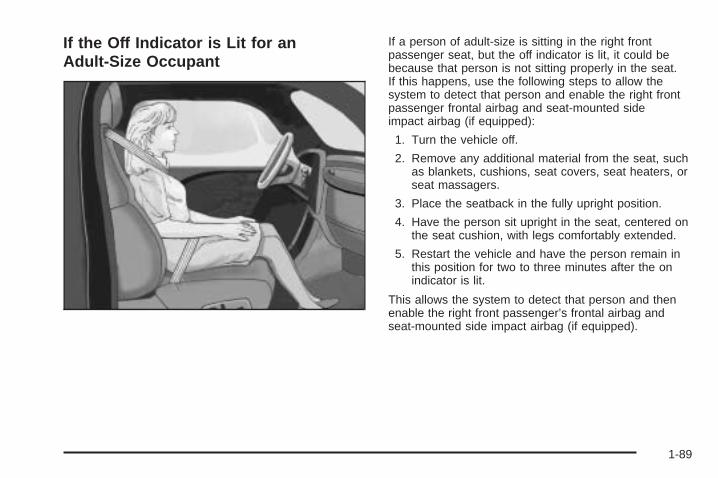
If the Off Indicator is Lit for anAdult-Size Occupant
If a person of adult-size is sitting in the right frontpassenger seat, but the off indicator is lit, it could bebecause that person is not sitting properly in the seat.If this happens, use the following steps to allow thesystem to detect that person and enable the right frontpassenger frontal airbag and seat-mounted sideimpact airbag (if equipped):
1. Turn the vehicle off.
2. Remove any additional material from the seat, suchas blankets, cushions, seat covers, seat heaters, orseat massagers.
3. Place the seatback in the fully upright position.
4. Have the person sit upright in the seat, centered onthe seat cushion, with legs comfortably extended.
5. Restart the vehicle and have the person remain inthis position for two to three minutes after the onindicator is lit.
This allows the system to detect that person and thenenable the right front passenger’s frontal airbag andseat-mounted side impact airbag (if equipped).
1-89
Additional Factors Affecting SystemOperationSafety belts help keep the passenger in position on theseat during vehicle maneuvers and braking, whichhelps the passenger sensing system maintain thepassenger airbag status. See “Safety Belts” and “ChildRestraints” in the Index for additional informationabout the importance of proper restraint use.
If you ever pull the shoulder portion of the belt out allthe way, you will engage the child restraint lockingfeature. This may unintentionally cause the passengersensing system to turn the airbag(s) off for someadult size occupants. If this happens, just let the belt goback all the way and start again.
A thick layer of additional material, such as a blanket orcushion, or aftermarket equipment such as seat covers,seat heaters, and seat massagers can affect how well thepassenger sensing system operates. We recommendthat you not use seat covers or other aftermarketequipment except when approved by GM for your specificvehicle. See Adding Equipment to Your Airbag-EquippedVehicle on page 1-91 for more information aboutmodifications that can affect how the system operates.
{CAUTION:
Stowing of articles under the passenger seat orbetween the passenger seat cushion and seatbackmay interfere with the proper operation of thepassenger sensing system.
Servicing Your Airbag-EquippedVehicleAirbags affect how the vehicle should be serviced.There are parts of the airbag system in several placesaround the vehicle. Your dealer/retailer and theservice manual have information about servicing thevehicle and the airbag system. To purchase a servicemanual, see Service Publications Ordering Informationon page 7-15.
1-90
{CAUTION:
For up to 10 seconds after the ignition is turned offand the battery is disconnected, an airbag can stillinflate during improper service. You can be injuredif you are close to an airbag when it inflates. Avoidyellow connectors. They are probably part of theairbag system. Be sure to follow proper serviceprocedures, and make sure the person performingwork for you is qualified to do so.
Adding Equipment to YourAirbag-Equipped Vehicle
Q: Is there anything I might add to or changeabout the vehicle that could keep the airbagsfrom working properly?
A: Yes. If you add things that change your vehicle’sframe, bumper system, height, front end or sidesheet metal, they may keep the airbag system fromworking properly. Changing or moving any partsof the front seats, safety belts, the airbag sensing
and diagnostic module, steering wheel, instrumentpanel, front sensors, or airbag wiring can affectthe operation of the airbag system.
In addition, the vehicle has a passenger sensingsystem for the right front passenger position, whichincludes sensors that are part of the passenger seat.The passenger sensing system may not operateproperly if the original seat trim is replaced withnon-GM covers, upholstery or trim, or with GMcovers, upholstery or trim designed for a differentvehicle. Any object, such as an aftermarket seatheater or a comfort enhancing pad or device,installed under or on top of the seat fabric, could alsointerfere with the operation of the passenger sensingsystem. This could either prevent proper deploymentof the passenger airbag(s) or prevent the passengersensing system from properly turning off thepassenger airbag(s). See Passenger SensingSystem on page 1-85.
If you have any questions about this, you shouldcontact Customer Assistance before you modifyyour vehicle. The phone numbers and addresses forCustomer Assistance are in Step Two of theCustomer Satisfaction Procedure in this manual.See Customer Satisfaction Procedure on page 7-2.
1-91
Q: Because I have a disability, I have to get myvehicle modified. How can I find out whetherthis will affect my airbag system?
A: If you have questions, call Customer Assistance.The phone numbers and addresses for CustomerAssistance are in Step Two of the CustomerSatisfaction Procedure in this manual. SeeCustomer Satisfaction Procedure on page 7-2.
In addition, your dealer/retailer and the service manualhave information about the location of the airbag sensors,sensing and diagnostic module and airbag wiring.
Restraint System Check
Checking the Restraint Systems
Safety BeltsNow and then, check the safety belt reminder light,safety belts, buckles, latch plates, retractors, andanchorages are all working properly.
If the vehicle has the built-in child restraint, alsoperiodically check the harness straps, latch plates,buckle, clip, child head restraint and anchorages areworking properly.
Look for any other loose or damaged safety belt systemparts that might keep a safety belt system from doingits job. See your dealer/retailer to have it repaired. Tornor frayed safety belts may not protect you in a crash.They can rip apart under impact forces. If a belt is tornor frayed, get a new one right away.
If the vehicle has the built-in child restraint, torn orfrayed harness straps can rip apart under impact forcesjust like torn or frayed safety belts can. They may notprotect a child in a crash. If a harness strap is tornor frayed, get a new harness right away.
Make sure the safety belt reminder light is working.See Safety Belt Reminders on page 3-32 for moreinformation.
Keep safety belts clean and dry. See Care of SafetyBelts and Built-in Child Restraint Harness on page 5-92for more information.
AirbagsThe airbag system does not need regularly scheduledmaintenance or replacement. Make sure the airbagreadiness light is working. See Airbag Readiness Lighton page 3-33 for more information.
1-92
Notice: If an airbag covering is damaged, opened,or broken, the airbag may not work properly.Do not open or break the airbag coverings. If thereare any opened or broken airbag covers, havethe airbag covering and/or airbag module replaced.For the location of the airbag modules, see WhatMakes an Airbag Inflate? on page 1-83. Seeyour dealer/retailer for service.
Replacing Restraint System PartsAfter a Crash
{CAUTION:
A crash can damage the restraint systems in yourvehicle. A damaged restraint system may notproperly protect the person using it, resulting inserious injury or even death in a crash. To helpmake sure your restraint systems are workingproperly after a crash, have them inspected andany necessary replacements made as soon aspossible.
If the vehicle has been in a crash, do you need newsafety belts or LATCH system (if equipped) parts?
After a very minor crash, nothing may be necessary.But the safety belt assemblies that were used during anycrash may have been stressed or damaged. See yourdealer/retailer to have the safety belt assembliesinspected or replaced.
If the vehicle has the LATCH system and it was beingused during a crash, you may need new LATCHsystem parts.
New parts and repairs may be necessary even if thesafety belt or LATCH system (if equipped), wasnot being used at the time of the crash.
If an airbag inflates, you will need to replace airbagsystem parts. See the part on the airbag system earlierin this section.
Have the safety belt pretensioners checked if thevehicle has been in a crash, if the airbag readiness lightstays on after the vehicle is started, or while you aredriving. See Airbag Readiness Light on page 3-33.
1-93

✍ NOTES
1-94
Keys ...............................................................2-3Remote Keyless Entry (RKE) System ................2-4Remote Keyless Entry (RKE) System
Operation ...................................................2-5Remote Vehicle Start ......................................2-7
Doors and Locks ............................................2-10Door Locks ..................................................2-10Power Door Locks ........................................2-11Delayed Locking ...........................................2-12Automatic Door Lock .....................................2-12Programmable Automatic Door Unlock .............2-13Lockout Protection ........................................2-13Dual Sliding Doors ........................................2-13Power Sliding Door (PSD) ..............................2-16Liftgate ........................................................2-22
Windows ........................................................2-24Power Windows ............................................2-25Manual Rear Quarter Windows .......................2-26Power Rear Quarter Windows ........................2-26Sun Visors ...................................................2-27
Theft-Deterrent Systems ..................................2-27Content Theft-Deterrent .................................2-27PASS-Key® III Electronic Immobilizer ...............2-29PASS-Key® III Electronic Immobilizer
Operation .................................................2-29Starting and Operating Your Vehicle ................2-31
New Vehicle Break-In ....................................2-31Ignition Positions ..........................................2-31Retained Accessory Power (RAP) ...................2-32Starting the Engine .......................................2-32Engine Coolant Heater ..................................2-34Automatic Transmission Operation ...................2-35Parking Brake ..............................................2-38Shifting Into Park ..........................................2-38Shifting Out of Park ......................................2-40Parking Over Things That Burn .......................2-40Engine Exhaust ............................................2-41Running the Vehicle While Parked ..................2-42
Section 2 Features and Controls
2-1
Mirrors ...........................................................2-43Manual Rearview Mirror .................................2-43Outside Power Mirrors ...................................2-43Outside Convex Mirror ...................................2-43Outside Heated Mirrors ..................................2-44
Object Detection Systems ...............................2-44Ultrasonic Rear Parking Assist (URPA) ............2-44
OnStar® System .............................................2-47Universal Home Remote System ......................2-50
Universal Home Remote System Operation(With One Triangular LED) ...........................2-51
Storage Areas ................................................2-55Glove Box ...................................................2-55Cupholders ..................................................2-55Overhead Console (Without Rail) ....................2-55Overhead Console (With Rail) ........................2-56Floor Console Storage Area ...........................2-58Folding Tray ................................................2-58Second Row Center Console ..........................2-58Luggage Carrier ...........................................2-59Convenience Net (With Rear
Convenience Center) .................................2-60Convenience Net (Without Rear
Convenience Center) .................................2-60Convenience Center ......................................2-61
Section 2 Features and Controls
2-2
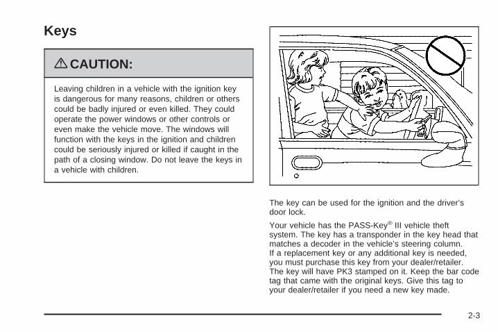
Keys
{CAUTION:
Leaving children in a vehicle with the ignition keyis dangerous for many reasons, children or otherscould be badly injured or even killed. They couldoperate the power windows or other controls oreven make the vehicle move. The windows willfunction with the keys in the ignition and childrencould be seriously injured or killed if caught in thepath of a closing window. Do not leave the keys ina vehicle with children.
The key can be used for the ignition and the driver’sdoor lock.
Your vehicle has the PASS-Key® III vehicle theftsystem. The key has a transponder in the key head thatmatches a decoder in the vehicle’s steering column.If a replacement key or any additional key is needed,you must purchase this key from your dealer/retailer.The key will have PK3 stamped on it. Keep the bar codetag that came with the original keys. Give this tag toyour dealer/retailer if you need a new key made.
2-3
Any new PASS-Key® III key must be programmedbefore it will start your vehicle. See PASS-Key® IIIElectronic Immobilizer on page 2-29 for more informationon programming your new key.
Notice: If you ever lock your keys in the vehicle,you may have to damage the vehicle to get in.Be sure you have spare keys.
If you are locked out of your vehicle, contact RoadsideAssistance. See Roadside Assistance Program onpage 7-7 for more information.
Remote Keyless Entry (RKE)SystemThe Remote Keyless Entry (RKE) system operates on aradio frequency subject to Federal CommunicationsCommission (FCC) Rules and with Industry Canada.
This device complies with Part 15 of the FCC Rules.Operation is subject to the following two conditions:
1. This device may not cause interference.
2. This device must accept any interference received,including interference that may cause undesiredoperation of the device.
This device complies with RSS-210 of Industry Canada.Operation is subject to the following two conditions:
1. This device may not cause interference.
2. This device must accept any interference received,including interference that may cause undesiredoperation of the device.
Changes or modifications to this system by other thanan authorized service facility could void authorization touse this equipment.
If there is a decrease in the RKE operating range,try this:
• Check the distance. The transmitter may be too farfrom the vehicle. Stand closer during rainy orsnowy weather.
• Check the location. Other vehicles or objects maybe blocking the signal. Take a few steps to theleft or right, hold the transmitter higher, andtry again.
• Check the transmitter’s battery. See “BatteryReplacement” later in this section.
• If the transmitter is still not working correctly, seeyour dealer/retailer or a qualified technician forservice.
2-4
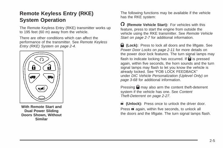
Remote Keyless Entry (RKE)System OperationThe Remote Keyless Entry (RKE) transmitter works upto 195 feet (60 m) away from the vehicle.
There are other conditions which can affect theperformance of the transmitter. See Remote KeylessEntry (RKE) System on page 2-4.
The following functions may be available if the vehiclehas the RKE system:
/ (Remote Vehicle Start): For vehicles with thisfeature, press to start the engine from outside thevehicle using the RKE transmitter. See Remote VehicleStart on page 2-7 for additional information.
Q (Lock): Press to lock all doors and the liftgate. SeePower Door Locks on page 2-11 for more details onthe power door lock features. The turn signal lamps mayflash to indicate locking has occurred. If Q is pressedagain, within five seconds, the horn sounds and the turnsignal lamps may flash to let you know the vehicle isalready locked. See “FOB LOCK FEEDBACK”under DIC Vehicle Personalization (Uplevel Only) onpage 3-68 for additional information.
Pressing Q may also arm the content theft-deterrentsystem if the vehicle has one. See ContentTheft-Deterrent on page 2-27.
" (Unlock): Press once to unlock the driver door.Press " again, within five seconds, to unlock allthe doors and the liftgate. The turn signal lamps flash.
With Remote Start andDual Power Sliding
Doors Shown, WithoutSimilar
2-5
To unlock all doors the first time " is pressed, see“FOB UNLOCK ON 1ST PRESS” under DIC VehiclePersonalization (Uplevel Only) on page 3-68.
Pressing " may disarm the content theft-deterrentsystem if the vehicle has one. See ContentTheft-Deterrent on page 2-27.
L (Remote Alarm): Press to sound the alarm. Theturn signal lamps flash and the horn sounds. PressL again to turn off the alarm.
Remote Power Sliding Door Operation
+ (Power Sliding Door): For vehicles with apower sliding door, press and hold + to open or closethe power sliding door. See Power Sliding Door (PSD)on page 2-16.
*+ (Dual Power Sliding Doors): For vehicleswith dual power sliding doors, press and hold *to open or close the driver side door or + to open orclose the passenger side door. See Power SlidingDoor (PSD) on page 2-16.
Operating the power sliding door(s) with the RKEtransmitter occurs if the power sliding door overrideswitch(es) on the overhead console are active orinactive. See Power Sliding Door (PSD) on page 2-16for additional information.
If the sliding door is closed and the power sliding doorbutton on the transmitter is pressed and held, thevehicle’s doors unlock and then the power sliding dooropens. If the power sliding door has been lockedusing the manual door lock lever, the power sliding doormust be unlocked before it can be opened with theRKE transmitter sliding door button.
If the vehicle’s fuel filler door is opened, the driver sidepower sliding door will not open completely. Do nottry to force the door. Once the fuel filler door is closed,the driver side sliding door can be opened normally.
Programming Transmitters to theVehicleOnly RKE transmitters programmed to this vehicle willwork. If a transmitter is lost or stolen, a replacementcan be purchased and programmed through yourdealer/retailer. When the replacement transmitter isprogrammed to this vehicle, all remaining transmittersmust also be reprogrammed. Any lost or stolentransmitters will no longer work once the new transmitteris programmed. The vehicle can have a maximum offour transmitters programmed to it.
2-6
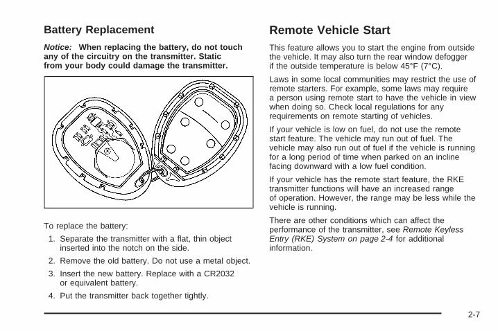
Battery Replacement
Notice: When replacing the battery, do not touchany of the circuitry on the transmitter. Staticfrom your body could damage the transmitter.
To replace the battery:
1. Separate the transmitter with a flat, thin objectinserted into the notch on the side.
2. Remove the old battery. Do not use a metal object.
3. Insert the new battery. Replace with a CR2032or equivalent battery.
4. Put the transmitter back together tightly.
Remote Vehicle StartThis feature allows you to start the engine from outsidethe vehicle. It may also turn the rear window defoggerif the outside temperature is below 45°F (7°C).
Laws in some local communities may restrict the use ofremote starters. For example, some laws may requirea person using remote start to have the vehicle in viewwhen doing so. Check local regulations for anyrequirements on remote starting of vehicles.
If your vehicle is low on fuel, do not use the remotestart feature. The vehicle may run out of fuel. Thevehicle may also run out of fuel if the vehicle is runningfor a long period of time when parked on an inclinefacing downward with a low fuel condition.
If your vehicle has the remote start feature, the RKEtransmitter functions will have an increased rangeof operation. However, the range may be less while thevehicle is running.
There are other conditions which can affect theperformance of the transmitter, see Remote KeylessEntry (RKE) System on page 2-4 for additionalinformation.
2-7
/ (Remote Vehicle Start): This button will be on theRKE transmitter if you have remote start.
To start the engine using the remote start feature, dothe following:
1. Aim the RKE transmitter, equipped with the remotevehicle start button, at the vehicle.
2. Press and release the transmitter’s lock button,then immediately press and hold the remotevehicle start button until the vehicle’s turn signallamps flash, or for at least two seconds, if thevehicle’s lights are not visible. The vehicle’s doorswill be locked.When the vehicle’s engine starts, the parking lampswill turn on and remain on while the engine isrunning.
3. If it is the first remote start since the vehicle hasbeen driven, repeat these steps, while the engineis still running, to extend the engine running timeby 10 minutes. Remote start can be extendedone time.
After a remote start, the engine will automatically shutoff after 10 minutes unless a time extension hasbeen done or the vehicle’s key is inserted into theignition switch and turned to ON/RUN.
The maximum number of remote starts or remote startattempts between ignition cycles with the key is two.
If the remote start procedure is used again beforethe first 10 minute time frame has ended, the first10 minutes will immediately expire and the second10 minute time frame will start.
After your vehicle’s engine has been started two timesusing the remote start button, the vehicle’s ignitionswitch must be turned to ON/RUN and then back toLOCK/OFF using the key before the remote startprocedure can be used again.
After entering the vehicle during a remote start, insertand turn the key to ON/RUN to drive the vehicle.
To manually shut off the engine after a remote start, doany of the following:
• Aim the RKE transmitter at the vehicle and pressthe remote start button until the parking lampsturn off.
• Turn on the hazard warning flashers.
• Insert the vehicle’s key into the ignition switch andturn the switch to ON/RUN and then back toLOCK/OFF.
2-8
The remote vehicle start feature will not operate if:
• The remote start system is disabled. See “REMOTESTART” under DIC Vehicle Personalization (UplevelOnly) on page 3-68.
• The vehicle’s key is in the ignition.
• The vehicle’s hood, liftgate or doors are not closed.
• The hazard warning flashers are on.
• There is an emission control system malfunction.
• The engine coolant temperature is too high.
• The oil pressure is low.
• Two remote vehicle starts have already beenprovided. The maximum number of remote starts orremote start attempts between ignition cycleswith the key is two.
Remote Start ReadyIf your vehicle does not have the remote vehicle startfeature, it may have the remote start ready feature. Thisfeature allows your dealer/retailer to add themanufacturer’s remote vehicle start feature.
See your dealer/retailer if you would like to add themanufacturer’s remote vehicle start feature to yourvehicle.
2-9
Doors and Locks
Door Locks
{CAUTION:
Unlocked doors can be dangerous.• Passengers, especially children, can easily
open the doors and fall out of a moving vehicle.When a door is locked, the handle will not openit. You increase the chance of being thrown outof the vehicle in a crash if the doors are notlocked. So, wear safety belts properly and lockthe doors whenever you drive.
• Young children who get into unlocked vehiclesmay be unable to get out. A child can beovercome by extreme heat and can sufferpermanent injuries or even death from heatstroke. Always lock your vehicle whenever youleave it.
• Outsiders can easily enter through an unlockeddoor when you slow down or stop your vehicle.Locking your doors can help prevent this fromhappening.
There are several ways to lock and unlock your vehicle.
From the outside, use your key or the remote keylessentry transmitter.
To unlock the driver’s door from the outside with thekey, insert the key and turn it toward the front ofthe vehicle. To lock the driver’s door from the outsidewith your key, insert the key and turn it toward the rearof the vehicle.
If your vehicle has power door locks, you may be ableto unlock all of the doors and the liftgate when you insertthe key, turn it toward the front of the vehicle, andhold it there for one second. You may be able to lock allof the doors when you insert the key and turn it towardthe rear of the vehicle.
2-10
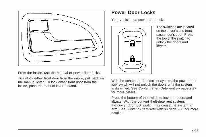
From the inside, use the manual or power door locks.
To unlock either front door from the inside, pull back onthe manual lever. To lock either front door from theinside, push the manual lever forward.
Power Door LocksYour vehicle has power door locks.
The switches are locatedon the driver’s and frontpassenger’s door. Pressthe top of the switch tounlock the doors andliftgate.
With the content theft-deterrent system, the power doorlock switch will not unlock the doors until the systemis disarmed. See Content Theft-Deterrent on page 2-27for more details.
Press the bottom of the switch to lock the doors andliftgate. With the content theft-deterrent system,the power door lock switch may cause the system toarm. See Content Theft-Deterrent on page 2-27 for moredetails.
2-11
Delayed LockingThis feature allows the locking of the vehicle to bedelayed until all doors have been closed forapproximately five seconds.
To activate the delayed locking feature, do one of thefollowing:
• Press the driver’s door power lock switch one timewhile the driver’s door is open.
• Press the passenger’s door power lock switch onetime while the passenger’s door is open.
• Press the lock button on the remote keyless entrytransmitter one time while any door is open.
Two chimes will sound to signal that delayed locking isactive.
The doors may be locked immediately by repeating anyof the above actions more than one time.
If a door remains open, without any other door beingopened or closed, the vehicle will lock afterapproximately 45 seconds.
If the key is in the ignition, this feature will not lockthe doors.
To turn the delayed locking feature off or on, see DICVehicle Personalization (Uplevel Only) on page 3-68.
Sliding Door Delayed LockingIf either sliding door is open when you use the powerdoor locks to lock the vehicle, the sliding door thatis open will not lock. Normally the delayed lockingfeature will be used to lock the sliding door after it hasbeen closed.
The sliding door delayed locking feature will lock yoursliding door(s) in situations where the delayedlocking feature does not apply or was overridden orprogrammed to be off. See “Delayed Locking” earlier inthis section. Shortly after the last sliding door isclosed, all the doors will lock.
Automatic Door LockAll of the doors will lock automatically when you movethe shift lever out of PARK (P). This feature cannotbe disabled.
If someone needs to get out of the vehicle while it is notin PARK (P), shift into PARK (P), or, have that personuse the manual lever or the power door lock switch.When the door is closed again, it will lock whenthe vehicle exceeds 5 mph (8 km/h).
With automatic door locks, you can lock or unlock thedoors at any time, either manually or by using the powerdoor lock switches.
2-12
Programmable Automatic DoorUnlockYour vehicle was programmed so that all doors willunlock automatically when the shift lever is moved intoPARK (P).
To change the way the automatic door unlockingoperates, see DIC Vehicle Personalization (UplevelOnly) on page 3-68.
Lockout ProtectionThe lockout protection feature makes it more difficult tolock the key in the vehicle. If the driver’s door isopen while the key is in the ignition, the door cannot belocked with the power door lock switch.
This feature cannot guarantee that you will never belocked out of the vehicle. If the key is not left inthe ignition, or, if the manual door lock is used, the keycould still be locked inside the vehicle. Alwaysremember to take the key with you.
Dual Sliding DoorsTo open either sliding door from outside the vehicle, pullthe handle out and then pull the door toward the rear.If you slide the door all the way back, the door will rest ina detent position.
To move the door forward, you must first pull the doorpast the open detent position.
The driver’s side sliding door is designed to open only alittle if the fuel door is open. If this ever happens, donot try to force the sliding door. Just close the driver’sside sliding door. Then when the fuel filler door isclosed, the driver’s side sliding door can be openednormally.
2-13
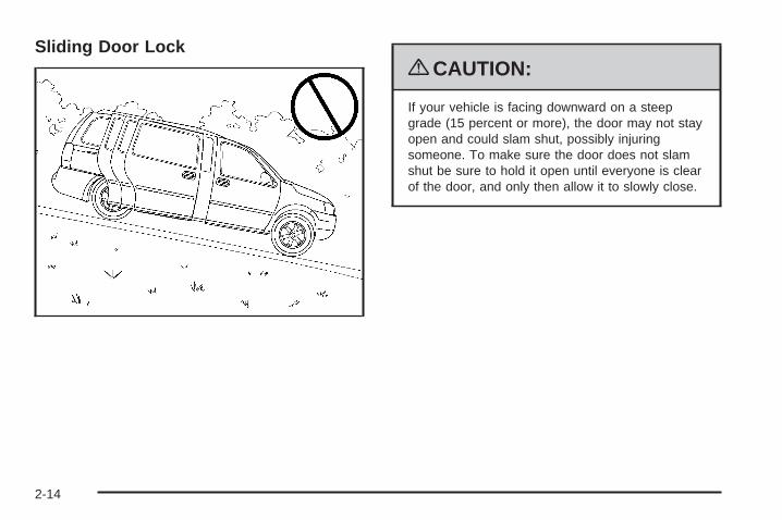
Sliding Door Lock{CAUTION:
If your vehicle is facing downward on a steepgrade (15 percent or more), the door may not stayopen and could slam shut, possibly injuringsomeone. To make sure the door does not slamshut be sure to hold it open until everyone is clearof the door, and only then allow it to slowly close.
2-14
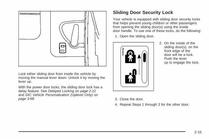
Lock either sliding door from inside the vehicle bymoving the manual lever down. Unlock it by moving thelever up.
With the power door locks, the sliding door lock has adelay feature. See Delayed Locking on page 2-12and DIC Vehicle Personalization (Uplevel Only) onpage 3-68.
Sliding Door Security LockYour vehicle is equipped with sliding door security locksthat helps prevent young children or other passengersfrom opening the sliding door(s) using the insidedoor handle. To use one of these locks, do the following:
1. Open the sliding door.
2. On the inside of thesliding door(s), on thefront edge of thedoor will be a lock.Push the leverup to engage the lock.
3. Close the door.
4. Repeat Steps 1 through 3 for the other door.
2-15
If your vehicle has power sliding door(s), you canprevent power opening of the sliding door from thepassenger power sliding door (PSD) activation switch bypressing the PSD second row passenger override(deactivation) switch located on the overhead console.See Power Sliding Door (PSD) on page 2-16.
If you want to open the sliding door while the securitylock is on, unlock and open the door from the outside.
You should let adults and older children know howthe security lock works, and how to cancel the lock. Ifyou do not, adults or older children who ride in the rearwill not be able to open the sliding door from theinside while the security lock feature is in use.
Canceling the Sliding DoorSecurity Lock1. Unlock the sliding door and open the door from the
outside.
2. Push the security lock lever all the way down.
3. Close the door.
4. Repeat Steps 1 through 3 for the other door.
The sliding door lock will now work normally.
Power Sliding Door (PSD)If your vehicle has this feature, you can open and closethe power sliding door(s) using the switches insideyour vehicle. You can also operate the sliding door(s)with your remote keyless entry transmitter. See RemoteKeyless Entry (RKE) System on page 2-4.
{CAUTION:
Leaving your children or pets unattended in yourvehicle can be dangerous. They could operate thepower sliding door. A child or others could beinjured. Do not leave children or pets unattendedin your vehicle.
2-16
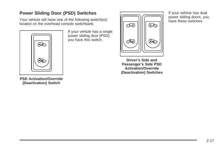
Power Sliding Door (PSD) SwitchesYour vehicle will have one of the following switch(es)located on the overhead console switchbank.
If your vehicle has a singlepower sliding door (PSD),you have this switch.
If your vehicle has dualpower sliding doors, youhave these switches.
PSD Activation/Override(Deactivation) Switch
Driver’s Side andPassenger’s Side PSD
Activation/Override(Deactivation) Switches
2-17
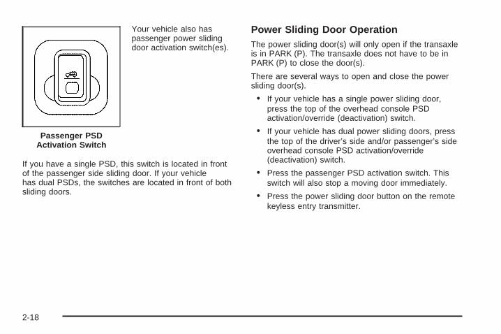
Your vehicle also haspassenger power slidingdoor activation switch(es).
If you have a single PSD, this switch is located in frontof the passenger side sliding door. If your vehiclehas dual PSDs, the switches are located in front of bothsliding doors.
Power Sliding Door OperationThe power sliding door(s) will only open if the transaxleis in PARK (P). The transaxle does not have to be inPARK (P) to close the door(s).
There are several ways to open and close the powersliding door(s).
• If your vehicle has a single power sliding door,press the top of the overhead console PSDactivation/override (deactivation) switch.
• If your vehicle has dual power sliding doors, pressthe top of the driver’s side and/or passenger’s sideoverhead console PSD activation/override(deactivation) switch.
• Press the passenger PSD activation switch. Thisswitch will also stop a moving door immediately.
• Press the power sliding door button on the remotekeyless entry transmitter.
Passenger PSDActivation Switch
2-18
• To manually open the power sliding door(s) whilethe switch(es) are in the activation position, pulland release the inside or outside door handleto release the door latch. The door will fully open.
• To manually close the power sliding door(s) whilethe switches are in the activation position, pull theinside or outside door handle or the edge ofthe door. Move the door about 4 inches (10 cm)toward the closed position and release it. The doorwill close completely and latch.
If a power sliding door is locked, it cannot be unlockedand opened using the overhead console PSDswitch(es) or the passenger PSD activation switch(es).The power sliding door must either be manuallyunlocked or unlocked using the power door unlockswitch located on the driver’s or front passenger’sarmrest, and then opened using the overhead orpassenger PSD activation switch(es).
The remote keyless entry transmitter can also be usedto open the power sliding door(s). If the vehicle islocked, press the power sliding door button(s) and alldoors will unlock and the sliding door(s) will open.See Remote Keyless Entry (RKE) System Operation onpage 2-5.
If the power sliding door has been manually locked, youmust unlock the PSD before it can be opened.
Notice: If you leave the power sliding door onwhen you go through an automatic car wash, thedoor may accidentally open. Be sure the powersliding door is turned off when going through acar wash.
If the power sliding door(s) is open or in the process ofclosing when you shift out of PARK (P), a chime willsound. This is a warning that the sliding door(s) is notcompletely closed. Also, the Driver InformationCenter (DIC) will indicate if the door is open. See DICWarnings and Messages on page 3-51. Stop the vehicleand close the door.
{CAUTION:
If you shift the transaxle out of PARK (P) andaccelerate before the power sliding door latchesclosed, the door may reverse to the open position.A child or others could fall out of the vehicle andbe injured. Always make sure the power slidingdoor is closed and latched before you drive away.
2-19
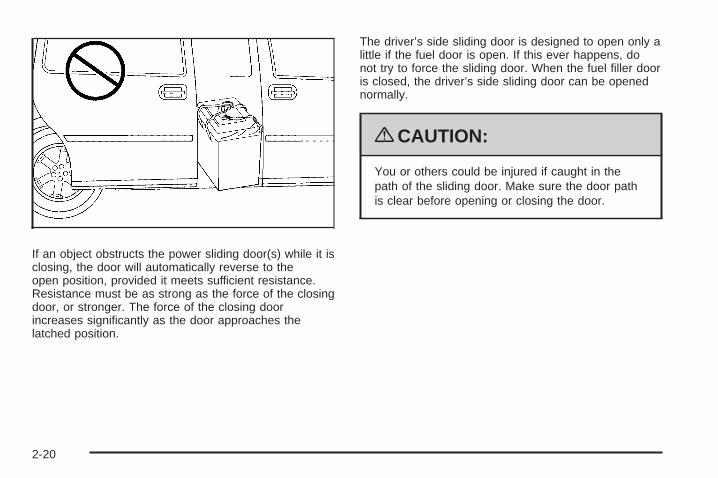
If an object obstructs the power sliding door(s) while it isclosing, the door will automatically reverse to theopen position, provided it meets sufficient resistance.Resistance must be as strong as the force of the closingdoor, or stronger. The force of the closing doorincreases significantly as the door approaches thelatched position.
The driver’s side sliding door is designed to open only alittle if the fuel door is open. If this ever happens, donot try to force the sliding door. When the fuel filler dooris closed, the driver’s side sliding door can be openednormally.
{CAUTION:
You or others could be injured if caught in thepath of the sliding door. Make sure the door pathis clear before opening or closing the door.
2-20
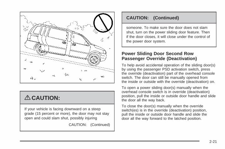
{CAUTION:
If your vehicle is facing downward on a steepgrade (15 percent or more), the door may not stayopen and could slam shut, possibly injuring
CAUTION: (Continued)
CAUTION: (Continued)
someone. To make sure the door does not slamshut, turn on the power sliding door feature. Thenif the door closes, it will close under the control ofthe power door system.
Power Sliding Door Second RowPassenger Override (Deactivation)To help avoid accidental operation of the sliding door(s)by using the passenger PSD activation switch, pressthe override (deactivation) part of the overhead consoleswitch. The door can still be manually opened fromthe inside or outside with the override (deactivation) on.
To open a power sliding door(s) manually when theoverhead console switch is in override (deactivation)position, pull the inside or outside door handle and slidethe door all the way back.
To close the door(s) manually when the overrideswitch(es) is in the override (deactivation) position,pull the inside or outside door handle and slide thedoor all the way forward to the latched position.
2-21
To stop the door(s) immediately while the door(s)is opening or closing, press the PSD override(deactivation) part of the switch.
Pressing the PSD button(s) on the remote keyless entrywill open and close the door unless the door hasbeen manually locked using the mechanical slider.
Resetting the Power Sliding DoorThe power sliding door may operate incorrectly or not atall because of the following conditions:
• A low voltage or dead battery
• A disconnected battery
• If the instrument panel PSD/fuse 21, LHPSD/fuse 24 or RHPSD/fuse 25 are removed or blown.
See Fuses and Circuit Breakers on page 5-98 for moreinformation.
If any of these conditions occur, the power sliding doormay need to be reset. If your vehicle has the dualpower sliding doors, both doors will have to be reset. Toreset a door, do the following:
1. Check to be sure the power sliding door is unlockedand securely closed.
2. Turn the ignition to LOCK.
3. If the power sliding door overhead console switch isin the override (deactivation) position, return to theactivation position.
4. Open the sliding door using the remote keylessentry transmitter, overhead console switch, orpassenger switch. Allow the door to travelfully open.
If the door does not travel to the fully open position,press the overhead console switch to the override(deactivation) position and slide the door fully open andclosed. Check for foreign objects in the tracks. Repeatthe procedure starting with Step 1. If the door resiststravel to the fully open position, see your dealerfor service.
LiftgateTo unlock or lock the liftgate from the outside, use theremote keyless entry transmitter. For more information,see Remote Keyless Entry (RKE) System Operationon page 2-5.
You can also use the power door lock switch to lockand unlock the liftgate.
Open the liftgate using the handle located above thelicense plate. Once slightly opened, the liftgate will riseby itself. Lamps in the rear of the vehicle will comeon, illuminating the rear cargo area.
2-22
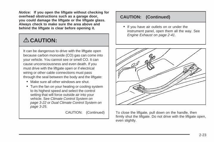
Notice: If you open the liftgate without checking foroverhead obstructions such as a garage door,you could damage the liftgate or the liftgate glass.Always check to make sure the area above andbehind the liftgate is clear before opening it.
{CAUTION:
It can be dangerous to drive with the liftgate openbecause carbon monoxide (CO) gas can come intoyour vehicle. You cannot see or smell CO. It cancause unconsciousness and even death. If youmust drive with the liftgate open or if electricalwiring or other cable connections must passthrough the seal between the body and the liftgate:
• Make sure all other windows are shut.• Turn the fan on your heating or cooling system
to its highest speed and select the controlsetting that will force outside air into yourvehicle. See Climate Control System onpage 3-22 or Dual Climate Control System onpage 3-25.
CAUTION: (Continued)
CAUTION: (Continued)
• If you have air outlets on or under theinstrument panel, open them all the way. SeeEngine Exhaust on page 2-41.
To close the liftgate, pull down on the handle, thenfirmly shut the liftgate. Do not drive with the liftgate open,even slightly.
2-23
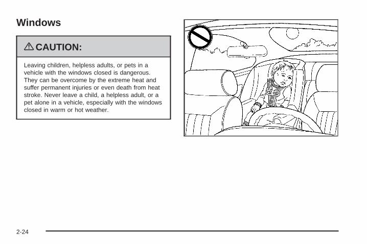
Windows
{CAUTION:
Leaving children, helpless adults, or pets in avehicle with the windows closed is dangerous.They can be overcome by the extreme heat andsuffer permanent injuries or even death from heatstroke. Never leave a child, a helpless adult, or apet alone in a vehicle, especially with the windowsclosed in warm or hot weather.
2-24

Power Windows
{CAUTION:
Leaving children in a vehicle with the keys isdangerous for many reasons, children or otherscould be badly injured or even killed. They couldoperate the power windows or other controls oreven make the vehicle move. The windows willfunction and they could be seriously injured orkilled if caught in the path of a closing window. Donot leave keys in a vehicle with children.
When there are children in the rear seat use thewindow lockout button to prevent unintentionaloperation of the windows.
The switches on thedriver’s door armrestcontrol the front windowswhen the ignition is inRUN, ACCESSORYor when RetainedAccessory Power (RAP) isactive. See RetainedAccessory Power (RAP)on page 2-32.
The driver’s power window switch has two downpositions. The first position lowers the window normally.
To raise the window, pull up the front of the switch.
Express-Down WindowTo activate the express-down feature, push the AUTOswitch all the way down to the second position, thenrelease it. The window will lower completely. To stop thewindow from lowering all the way, pull up on the frontof the switch.
2-25
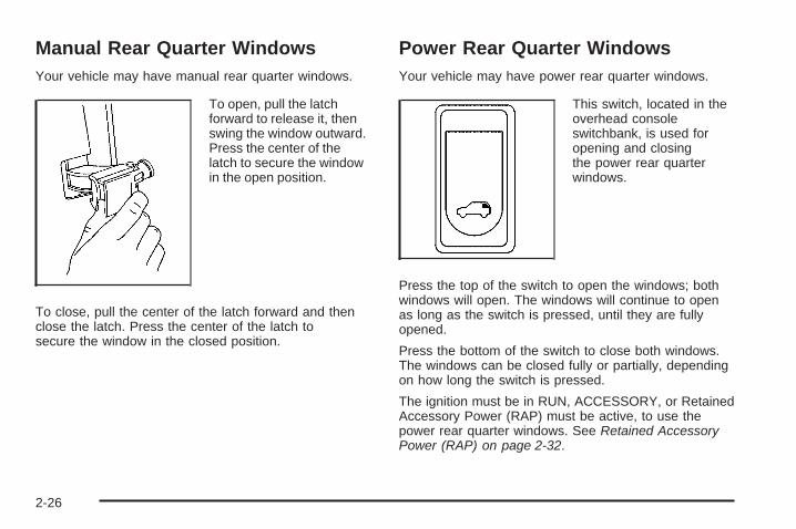
Manual Rear Quarter WindowsYour vehicle may have manual rear quarter windows.
To open, pull the latchforward to release it, thenswing the window outward.Press the center of thelatch to secure the windowin the open position.
To close, pull the center of the latch forward and thenclose the latch. Press the center of the latch tosecure the window in the closed position.
Power Rear Quarter WindowsYour vehicle may have power rear quarter windows.
This switch, located in theoverhead consoleswitchbank, is used foropening and closingthe power rear quarterwindows.
Press the top of the switch to open the windows; bothwindows will open. The windows will continue to openas long as the switch is pressed, until they are fullyopened.
Press the bottom of the switch to close both windows.The windows can be closed fully or partially, dependingon how long the switch is pressed.
The ignition must be in RUN, ACCESSORY, or RetainedAccessory Power (RAP) must be active, to use thepower rear quarter windows. See Retained AccessoryPower (RAP) on page 2-32.
2-26
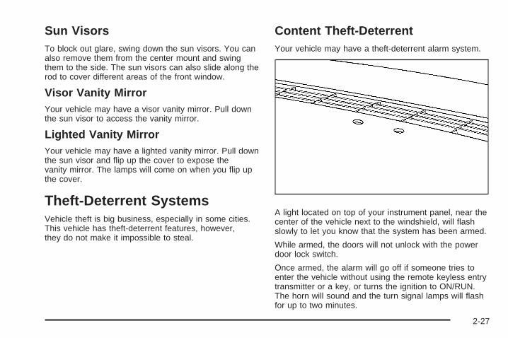
Sun VisorsTo block out glare, swing down the sun visors. You canalso remove them from the center mount and swingthem to the side. The sun visors can also slide along therod to cover different areas of the front window.
Visor Vanity MirrorYour vehicle may have a visor vanity mirror. Pull downthe sun visor to access the vanity mirror.
Lighted Vanity MirrorYour vehicle may have a lighted vanity mirror. Pull downthe sun visor and flip up the cover to expose thevanity mirror. The lamps will come on when you flip upthe cover.
Theft-Deterrent SystemsVehicle theft is big business, especially in some cities.This vehicle has theft-deterrent features, however,they do not make it impossible to steal.
Content Theft-DeterrentYour vehicle may have a theft-deterrent alarm system.
A light located on top of your instrument panel, near thecenter of the vehicle next to the windshield, will flashslowly to let you know that the system has been armed.
While armed, the doors will not unlock with the powerdoor lock switch.
Once armed, the alarm will go off if someone tries toenter the vehicle without using the remote keyless entrytransmitter or a key, or turns the ignition to ON/RUN.The horn will sound and the turn signal lamps will flashfor up to two minutes.
2-27
Arming with the Power Lock SwitchYour alarm system will arm when the key is removedfrom the ignition and you use the driver’s powerdoor lock switch, with the driver’s door open or thepassenger’s door power door lock switch with thepassenger’s door open to lock the vehicle. If you wouldlike to turn on power door lock switch arming, seeDIC Vehicle Personalization (Uplevel Only) onpage 3-68.
When the security light flashes quickly the system isarming. After all doors and the liftgate are closedand locked, the security light will begin flashing at avery slow rate to let you know the system is armed.
Arming with the Remote Keyless EntryTransmitterYour alarm system will arm if the key is not in theignition and you use your remote keyless entrytransmitter to lock the doors. The security light will flashto let you know the system is arming. If you pressthe transmitter’s lock button twice within five seconds,the horn will sound. After all doors and the liftgateare closed and locked, the security light will beginflashing at a very slow rate to let you know the systemis armed.
Arming with Your KeyYour alarm system will arm when you use your key tolock the driver’s door. The security light will flash tolet you know the system is arming. After all doors andthe liftgate are closed and locked, the security lightwill begin flashing at a very slow rate to let you know thesystem is armed. If you would like your key not toarm the system, see DIC Vehicle Personalization(Uplevel Only) on page 3-68.
Arming ConfirmationIf remote unlock confirmation is on, the turn signallamps will flash briefly to let you know when your alarmsystem has disarmed. If you would not like the turnsignal lamps to flash, see DIC Vehicle Personalization(Uplevel Only) on page 3-68.
Disarming with the Remote KeylessEntry TransmitterYour alarm system will disarm when you use yourremote keyless entry transmitter to unlock the doors.The security light will stop flashing to let you know thesystem is no longer armed.
2-28
Disarming with Your KeyYour alarm system will disarm when you use your keyto unlock the driver’s door. The security light willstop flashing to let you know the system is no longerarmed. If you would like your key not to disarm the alarmsystem, see DIC Vehicle Personalization (UplevelOnly) on page 3-68.
PASS-Key® III ElectronicImmobilizerYour PASS-Key III system operates on a radiofrequency subject to Federal CommunicationsCommission (FCC) Rules and with Industry Canada.
This device complies with Part 15 of the FCC Rules.Operation is subject to the following two conditions:
1. This device may not cause harmful interference.
2. This device must accept any interference received,including interference that may cause undesiredoperation.
This device complies with RSS-210 of Industry Canada.Operation is subject to the following two conditions:
1. This device may not cause interference.
2. This device must accept any interference received,including interference that may cause undesiredoperation of the device.
Changes or modifications to this system by other thanan authorized service facility could void authorization touse this equipment.
PASS-Key III uses a radio frequency transponder in thekey that matches a decoder in your vehicle.
PASS-Key® III ElectronicImmobilizer OperationYour vehicle is equipped with the PASS-Key® III(Personalized Automotive Security System)theft-deterrent system. PASS-Key® III is a passivetheft deterrent system.
The system is automatically armed when the key isremoved from the ignition.
You do not have to manually arm or disarm the system.
The security light will come on if there is a problemwith arming or disarming the theft-deterrent system.
When the PASS-Key® III system senses that someoneis using the wrong key, it shuts down the vehicle’sstarter and fuel systems. The starter will not work andfuel will stop being delivered to the engine. Anyoneusing a trial-and-error method to start the vehicle will bediscouraged because of the high number of electricalkey codes.
2-29
If the engine does not start and the security messagecomes on, there may be a problem with yourtheft-deterrent system. Turn the ignition off andtry again.
If the engine still does not start, and the key appears tobe undamaged, try another ignition key. If the enginestill does not start with the other key, your vehicle needsservice. If your vehicle does start, the first key may befaulty. See your dealer/retailer or a locksmith whocan service the PASS-Key® III to have a new key made.
It is possible for the PASS-Key® III decoder to learnthe transponder value of a new or replacement key. Upto 10 keys may be programmed for the vehicle. Thisprocedure is for learning additional keys only. If all thecurrently programmed keys are lost or do not operate,you must see your dealer/retailer or a locksmith who canservice PASS-Key® III to have keys made andprogrammed to the system.
See your dealer/retailer or a locksmith who can servicePASS-Key® III to get a new key blank that is cutexactly as the ignition key that operates the system.
To program the new key:
1. Verify the new key has PK3 stamped on it.
2. Insert the original, already programmed key into theignition lock cylinder and start the engine. If theengine will not start, see your dealer/retailerfor service.
3. After the engine has started, turn the key toLOCK/OFF and remove the key.For vehicles first sold in Canada, repeat step 2 witha different, already programmed, key beforeproceeding to step 4.
4. Insert the key to be programmed and turn it toON/RUN within 10 seconds of removing theprevious key.The security message will turn off once the key hasbeen programmed. It may not be apparent thatthe security message went on due to how quicklythe key is programmed.
5. Repeat Steps 1 through 4 if additional keys are tobe programmed.
If you are ever driving and the security message comeson and stays on, you will be able to restart yourengine if you turn it off. Your PASS-Key® III system,however, is not working properly and must be servicedby your dealer/retailer. Your vehicle is not protectedby the PASS-Key® III system at this time.
If you lose or damage a PASS-Key® III key, see yourdealer/retailer or a locksmith who can servicePASS-Key® III to have a new key made.
Do not leave the key or device that disarms ordeactivates the theft deterrent system in the vehicle.
2-30
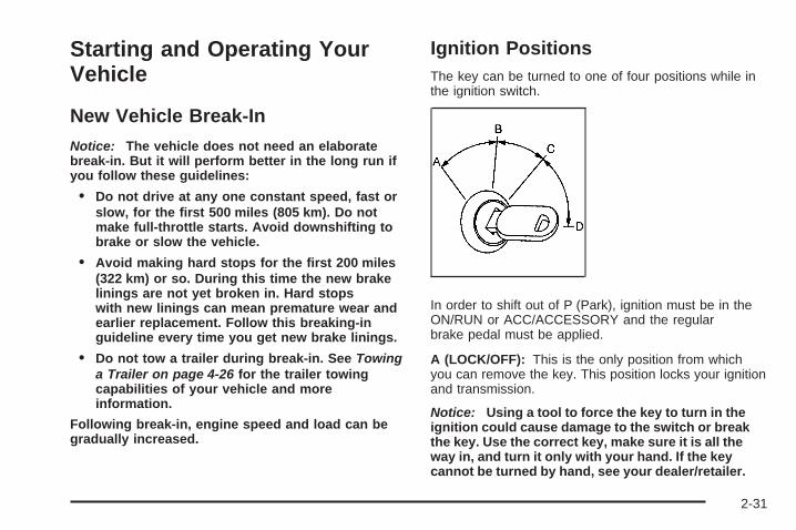
Starting and Operating YourVehicle
New Vehicle Break-InNotice: The vehicle does not need an elaboratebreak-in. But it will perform better in the long run ifyou follow these guidelines:
• Do not drive at any one constant speed, fast orslow, for the first 500 miles (805 km). Do notmake full-throttle starts. Avoid downshifting tobrake or slow the vehicle.
• Avoid making hard stops for the first 200 miles(322 km) or so. During this time the new brakelinings are not yet broken in. Hard stopswith new linings can mean premature wear andearlier replacement. Follow this breaking-inguideline every time you get new brake linings.
• Do not tow a trailer during break-in. See Towinga Trailer on page 4-26 for the trailer towingcapabilities of your vehicle and moreinformation.
Following break-in, engine speed and load can begradually increased.
Ignition PositionsThe key can be turned to one of four positions while inthe ignition switch.
In order to shift out of P (Park), ignition must be in theON/RUN or ACC/ACCESSORY and the regularbrake pedal must be applied.
A (LOCK/OFF): This is the only position from whichyou can remove the key. This position locks your ignitionand transmission.
Notice: Using a tool to force the key to turn in theignition could cause damage to the switch or breakthe key. Use the correct key, make sure it is all theway in, and turn it only with your hand. If the keycannot be turned by hand, see your dealer/retailer.
2-31

B (ACC/ACCESSORY): This is the position in whichyou can operate the electrical accessories, such asthe radio.
C (ON/RUN): This is the position to which the switchreturns after the engine is started and the ignition key isreleased. This is the position for driving. Even whilethe engine is not running, ON/RUN can be usedto operate your electrical accessories and to displaysome instrument panel warning lights.
The battery could be drained if you leave the key in theACC/ACCESSORY or ON/RUN position with theengine off. You may not be able to start your vehicle ifthe battery is allowed to drain for an extended periodof time.
D (START): This position starts the engine. When theengine starts, release the ignition key. The switchwill return to ON/RUN for driving.
Key In the IgnitionNever leave your vehicle with the keys inside, as it is aneasy target for joy riders or thieves. If you leave thekey in the ignition and park your vehicle, a chimewill sound, when you open the driver’s door. Alwaysremember to remove your key from the ignition and takeit with you. This will lock your ignition and transmission.Also, always remember to lock the doors.
The battery could be drained if you leave the key in theignition while your vehicle is parked. You may not beable to start your vehicle after it has been parked for anextended period of time.
Retained Accessory Power (RAP)These vehicle accessories can be used for up to10 minutes after the engine is turned off:
• Audio System
• Power Windows
These features continue to work up to 10 minutes afterthe engine is turned off or until either door is opened.If a door is opened, the power windows and audiosystem will shut off.
Starting the EngineMove the shift lever to P (Park) or N (Neutral). Theengine will not start in any other position. To restart theengine when the vehicle is already moving, useN (Neutral) only.
Notice: Do not try to shift to P (Park) if the vehicleis moving. If you do, you could damage thetransmission. Shift to P (Park) only when the vehicleis stopped.
2-32
Starting Procedure1. With your foot off the accelerator pedal, turn the
ignition to START. When the engine starts, let goof the key. The idle speed will slow down asthe engine warms. Do not race the engineimmediately after starting it. Operate the engine andtransmission gently to allow the oil to warm upand lubricate all moving parts.The vehicle has a Computer-Controlled CrankingSystem. This feature assists in starting theengine and protects components. If the ignition keyis turned to the START position, and thenreleased when the engine begins cranking, theengine will continue cranking for a few seconds oruntil the vehicle starts. If the engine does notstart and the key is held in START, cranking will bestopped after 15 seconds to prevent crankingmotor damage. To prevent gear damage, thissystem also prevents cranking if the engineis already running. Engine cranking can bestopped by turning the ignition switch to theACC/ACCESSORY or LOCK/OFF position.
Notice: Cranking the engine for long periods oftime, by returning the key to the START positionimmediately after cranking has ended, can overheatand damage the cranking motor, and drain thebattery. Wait at least 15 seconds between each try,to let the cranking motor cool down.
2. If the engine does not start after 5-10 seconds,especially in very cold weather (below 0°F or−18°C), it could be flooded with too much gasoline.Try pushing the accelerator pedal all the way tothe floor and holding it there as you hold the key inSTART for up to a maximum of 15 seconds.Wait at least 15 seconds between each try, to allowthe cranking motor to cool down. When theengine starts, let go of the key and accelerator. Ifthe vehicle starts briefly but then stops again, repeatthese steps. This clears the extra gasoline fromthe engine. Do not race the engine immediatelyafter starting it. Operate the engine andtransmission gently until the oil warms up andlubricates all moving parts.
Notice: The engine is designed to work with theelectronics in the vehicle. If you add electrical partsor accessories, you could change the way theengine operates. Before adding electrical equipment,check with your dealer/retailer. If you do not, theengine might not perform properly. Any resultingdamage would not be covered by the vehiclewarranty.
2-33
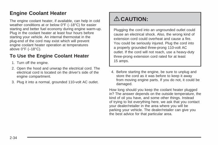
Engine Coolant HeaterThe engine coolant heater, if available, can help in coldweather conditions at or below 0°F (−18°C) for easierstarting and better fuel economy during engine warm-up.Plug in the coolant heater at least four hours beforestarting your vehicle. An internal thermostat in theplug-end of the cord may exist which will preventengine coolant heater operation at temperaturesabove 0°F (−18°C).
To Use the Engine Coolant Heater1. Turn off the engine.
2. Open the hood and unwrap the electrical cord. Theelectrical cord is located on the driver’s side of theengine compartment.
3. Plug it into a normal, grounded 110-volt AC outlet.
{CAUTION:
Plugging the cord into an ungrounded outlet couldcause an electrical shock. Also, the wrong kind ofextension cord could overheat and cause a fire.You could be seriously injured. Plug the cord intoa properly grounded three-prong 110-volt ACoutlet. If the cord will not reach, use a heavy-dutythree-prong extension cord rated for at least15 amps.
4. Before starting the engine, be sure to unplug andstore the cord as it was before to keep it awayfrom moving engine parts. If you do not, it could bedamaged.
How long should you keep the coolant heater pluggedin? The answer depends on the outside temperature, thekind of oil you have, and some other things. Insteadof trying to list everything here, we ask that you contactyour dealer/retailer in the area where you will beparking your vehicle. The dealer/retailer can give youthe best advice for that particular area.
2-34
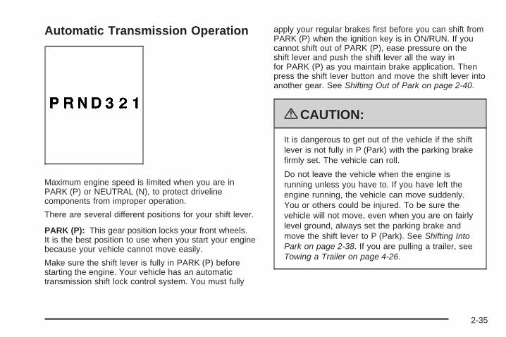
Automatic Transmission Operation
Maximum engine speed is limited when you are inPARK (P) or NEUTRAL (N), to protect drivelinecomponents from improper operation.
There are several different positions for your shift lever.
PARK (P): This gear position locks your front wheels.It is the best position to use when you start your enginebecause your vehicle cannot move easily.
Make sure the shift lever is fully in PARK (P) beforestarting the engine. Your vehicle has an automatictransmission shift lock control system. You must fully
apply your regular brakes first before you can shift fromPARK (P) when the ignition key is in ON/RUN. If youcannot shift out of PARK (P), ease pressure on theshift lever and push the shift lever all the way infor PARK (P) as you maintain brake application. Thenpress the shift lever button and move the shift lever intoanother gear. See Shifting Out of Park on page 2-40.
{CAUTION:
It is dangerous to get out of the vehicle if the shiftlever is not fully in P (Park) with the parking brakefirmly set. The vehicle can roll.
Do not leave the vehicle when the engine isrunning unless you have to. If you have left theengine running, the vehicle can move suddenly.You or others could be injured. To be sure thevehicle will not move, even when you are on fairlylevel ground, always set the parking brake andmove the shift lever to P (Park). See Shifting IntoPark on page 2-38. If you are pulling a trailer, seeTowing a Trailer on page 4-26.
2-35
REVERSE (R): Use this gear to back up.
Notice: Shifting to R (Reverse) while the vehicle ismoving forward could damage the transmission.The repairs would not be covered by the vehiclewarranty. Shift to R (Reverse) only after the vehicleis stopped.
To rock your vehicle back and forth to get out of snow,ice or sand without damaging your transmission,see If Your Vehicle is Stuck in Sand, Mud, Ice, or Snowon page 4-18.
NEUTRAL (N): In this position, your engine does notconnect with the wheels. To restart when you arealready moving, use NEUTRAL (N) only. Also, useNEUTRAL (N) when your vehicle is being towed.
{CAUTION:
Shifting into a drive gear while the engine isrunning at high speed is dangerous. Unless yourfoot is firmly on the brake pedal, the vehicle couldmove very rapidly. You could lose control and hitpeople or objects. Do not shift into a drive gearwhile the engine is running at high speed.
Notice: Shifting out of P (Park) or N (Neutral) withthe engine running at high speed may damagethe transmission. The repairs would not be coveredby the vehicle warranty. Be sure the engine isnot running at high speed when shifting the vehicle.
DRIVE (D): This position is for normal driving. Itprovides the best fuel economy for your vehicle. If youneed more power for passing, and you are:
• Going less than 35 mph (55 km/h), push youraccelerator pedal about halfway down.
• Going about 35 mph (55 km/h) or more, push theaccelerator all the way down.
The vehicle will shift down to the next gear and havemore power.
Downshifting the transmission in slippery road conditionscould result in skidding, see Skidding under Loss ofControl on page 4-11
Notice: If your vehicle seems to start up ratherslowly or not shift gears when you go faster, andyou continue to drive your vehicle that way, youcould damage the transmission. Have your vehicleserviced right away. You can drive in SECOND (2)when you are driving less than 35 mph (55 km/h) andDRIVE (D) for higher speeds until then.
2-36
Warm-Up ShiftYour vehicle has a computer controlled transmissiondesigned to warm up the engine faster when the outsidetemperature is 35°F (2°C) or colder. You may noticethat the transmission will shift at a higher vehicle speeduntil the engine is warmed up. This is a normalcondition designed to provide heat to the passengercompartment and defrost the windows more quickly. SeeClimate Control System on page 3-22 and DualClimate Control System on page 3-25 for moreinformation.
THIRD (3): This position is also used for normal driving.It reduces vehicle speed more than DRIVE (D) withoutusing your brakes. You might choose THIRD (3) insteadof DRIVE (D) when driving on hilly, winding roads,when towing a trailer, so there is less shifting betweengears and when going down a steep hill.
SECOND (2): This position reduces vehicle speed morethan DRIVE (D) without using your brakes. You can useSECOND (2) on hills. It can help control your speed asyou go down steep mountain roads, but then you wouldalso want to use your brakes off and on.
Notice: Driving in SECOND (2) for more than25 miles (40 km) or at speeds over 55 mph (90 km/h)may damage the transmission. Also, shifting intoSECOND (2) at speeds above 65 mph (105 km/h) cancause damage. Drive in THIRD (3) or DRIVE (D)instead of SECOND (2).
Notice: If your vehicle seems to start up ratherslowly, or if it seems not to shift gears as you gofaster, something may be wrong with a transmissionsystem sensor. If you drive very far that way, yourvehicle can be damaged. So, if this happens, haveyour vehicle serviced right away. Until then, you canuse SECOND (2) when you are driving less than35 mph (55 km/h) and THIRD (3) for higher speeds.
FIRST (1): This position reduces vehicle speed evenmore than SECOND (2) without using your brakes.You can use it on very steep hills, or in deep snow ormud. If the shift lever is put in FIRST (1) while thevehicle is moving forward, the transmission will not shiftinto first gear until the vehicle is going slowly enough.
Notice: Spinning the tires or holding the vehicle inone place on a hill using only the acceleratorpedal may damage the transmission. The repair willnot be covered by your warranty. If you are stuck,do not spin the tires. When stopping on a hill,use the brakes to hold the vehicle in place.
2-37
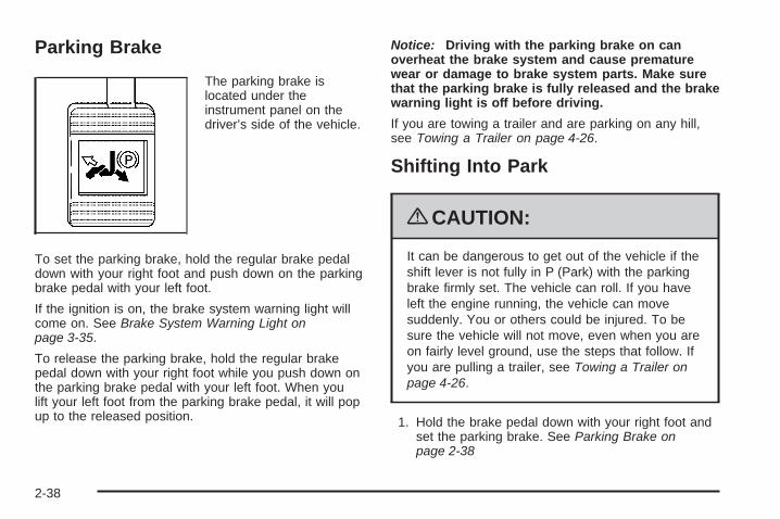
Parking Brake
The parking brake islocated under theinstrument panel on thedriver’s side of the vehicle.
To set the parking brake, hold the regular brake pedaldown with your right foot and push down on the parkingbrake pedal with your left foot.
If the ignition is on, the brake system warning light willcome on. See Brake System Warning Light onpage 3-35.
To release the parking brake, hold the regular brakepedal down with your right foot while you push down onthe parking brake pedal with your left foot. When youlift your left foot from the parking brake pedal, it will popup to the released position.
Notice: Driving with the parking brake on canoverheat the brake system and cause prematurewear or damage to brake system parts. Make surethat the parking brake is fully released and the brakewarning light is off before driving.
If you are towing a trailer and are parking on any hill,see Towing a Trailer on page 4-26.
Shifting Into Park
{CAUTION:
It can be dangerous to get out of the vehicle if theshift lever is not fully in P (Park) with the parkingbrake firmly set. The vehicle can roll. If you haveleft the engine running, the vehicle can movesuddenly. You or others could be injured. To besure the vehicle will not move, even when you areon fairly level ground, use the steps that follow. Ifyou are pulling a trailer, see Towing a Trailer onpage 4-26.
1. Hold the brake pedal down with your right foot andset the parking brake. See Parking Brake onpage 2-38
2-38
2. Move the shift lever into PARK (P) by pulling theshift lever toward you and moving it up as far as itwill go.
3. Turn the ignition key to LOCK/OFF.
4. Remove the key and take it with you. If you canleave your vehicle with the ignition key in yourhand, your vehicle is in PARK (P).
Leaving Your Vehicle With the EngineRunning
{CAUTION:
It can be dangerous to leave the vehicle with theengine running. The vehicle could move suddenlyif the shift lever is not fully in P (Park) with theparking brake firmly set. And, if you leave thevehicle with the engine running, it could overheatand even catch fire. You or others could beinjured. Do not leave the vehicle with the enginerunning.
If you have to leave your vehicle with the enginerunning, be sure your vehicle is in PARK (P) and theparking brake is firmly set before you leave it. After youmove the shift lever into PARK (P), hold the regularbrake pedal down. Then, see if you can move the shiftlever away from PARK (P) without first pulling ittoward you. If you can, it means that the shift lever wasnot fully locked into PARK (P).
Torque LockIf you are parking on a hill and you do not shift yourvehicle into PARK (P) properly, the weight of the vehiclemay put too much force on the parking pawl in thetransmission. You may find it difficult to pull the shiftlever out of PARK (P). This is called torque lock.To prevent torque lock, set the parking brake and thenshift into PARK (P) properly before you leave thedriver’s seat. To find out how, see Shifting Into Park onpage 2-38.
When you are ready to drive, move the shift lever out ofPARK (P) before you release the parking brake.
If torque lock does occur, you may need to have anothervehicle push yours a little uphill to take some of thepressure from the parking pawl in the transmission, soyou can pull the shift lever out of PARK (P).
2-39
Shifting Out of ParkThis vehicle is equipped with an electronic shift lockrelease system. The shift lock release is designed to:
• Prevent ignition key removal unless the shiftlever is in PARK (P) with the shift lever buttonfully released, and
• Prevent movement of the shift lever out ofPARK (P), unless the ignition is in ON/RUN orACC/ACCESSORY and the regular brake pedalis applied.
The shift lock release is always functional except inthe case of an uncharged or low voltage (less than9 volt) battery.
If your vehicle has an uncharged battery or a batterywith low voltage, try charging or jump starting thebattery. See Jump Starting on page 5-37 for moreinformation.
To shift out of PARK (P) use the following:
1. Apply the brake pedal.
2. Move the shift lever to the desired position.
If you still are unable to shift out of PARK (P):
1. Ease the pressure on the shift lever.
2. While holding down the brake pedal, press the shiftlever all the way into PARK (P).
3. Move the shift lever to the desired position.
If you are still having a problem shifting, then have yourvehicle serviced soon.
Parking Over Things That Burn
{CAUTION:
Things that can burn could touch hot exhaustparts under the vehicle and ignite. Do not parkover papers, leaves, dry grass, or other things thatcan burn.
2-40
Engine Exhaust
{CAUTION:
Engine exhaust contains Carbon Monoxide (CO)which cannot be seen or smelled. Exposure to COcan cause unconsciousness and even death.
Exhaust may enter the vehicle if:• The vehicle idles in areas with poor ventilation
(parking garages, tunnels, deep snow thatmay block underbody airflow or tail pipes).
• The exhaust smells or sounds strange ordifferent.
• The exhaust system leaks due to corrosion ordamage.
CAUTION: (Continued)
CAUTION: (Continued)
• The vehicle’s exhaust system has beenmodified, damaged or improperly repaired.
• There are holes or openings in the vehiclebody from damage or after-marketmodifications that are not completely sealed.
If unusual fumes are detected or if it is suspectedthat exhaust is coming into the vehicle:
• Drive it only with the windowscompletely down.
• Have the vehicle repaired immediately.
Never park the vehicle with the engine running inan enclosed area such as a garage or a buildingthat has no fresh air ventilation.
2-41
Running the Vehicle While ParkedIt is better not to park with the engine running. But if youever have to, here are some things to know.
{CAUTION:
Idling a vehicle in an enclosed area with poorventilation is dangerous. Engine exhaust mayenter the vehicle. Engine exhaust contains CarbonMonoxide (CO) which cannot be seen or smelled.It can cause unconsciousness and even death.Never run the engine in an enclosed area that hasno fresh air ventilation. For more information, seeEngine Exhaust Engine Exhaust on page 2-41.
{CAUTION:
It can be dangerous to get out of the vehicle if theautomatic transmission shift lever is not fully inP (Park) with the parking brake firmly set. Thevehicle can roll. Do not leave the vehicle when theengine is running unless you have to. If you haveleft the engine running, the vehicle can movesuddenly. You or others could be injured. To besure the vehicle will not move, even when you areon fairly level ground, always set the parkingbrake and move the shift lever to P (Park).
Follow the proper steps to be sure the vehicle will notmove. See Shifting Into Park on page 2-38.
If parking on a hill and pulling a trailer, see Towing aTrailer on page 4-26.
2-42
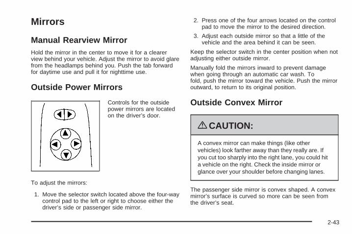
Mirrors
Manual Rearview MirrorHold the mirror in the center to move it for a clearerview behind your vehicle. Adjust the mirror to avoid glarefrom the headlamps behind you. Push the tab forwardfor daytime use and pull it for nighttime use.
Outside Power Mirrors
Controls for the outsidepower mirrors are locatedon the driver’s door.
To adjust the mirrors:
1. Move the selector switch located above the four-waycontrol pad to the left or right to choose either thedriver’s side or passenger side mirror.
2. Press one of the four arrows located on the controlpad to move the mirror to the desired direction.
3. Adjust each outside mirror so that a little of thevehicle and the area behind it can be seen.
Keep the selector switch in the center position when notadjusting either outside mirror.
Manually fold the mirrors inward to prevent damagewhen going through an automatic car wash. Tofold, push the mirror toward the vehicle. Push the mirroroutward, to return to its original position.
Outside Convex Mirror
{CAUTION:
A convex mirror can make things (like othervehicles) look farther away than they really are. Ifyou cut too sharply into the right lane, you could hita vehicle on the right. Check the inside mirror orglance over your shoulder before changing lanes.
The passenger side mirror is convex shaped. A convexmirror’s surface is curved so more can be seen fromthe driver’s seat.
2-43
Outside Heated MirrorsFor vehicles with heated mirrors:
< (Rear Window Defogger): Press to heat themirrors. See “Rear Window Defogger” under ClimateControl System on page 3-22.
Object Detection Systems
Ultrasonic Rear ParkingAssist (URPA)If the vehicle has the URPA system, it helps you parkeasier and avoid other vehicles while in R (Reverse). Itoperates at speeds less than 3 mph (5 km/h). It candetermine how close objects are to the rear bumper, upto 5 feet (1.5 m) behind the vehicle. The distancesensors are located on the rear bumper.
{CAUTION:
The Ultrasonic Rear Parking Assist (URPA)system does not replace driver vision. It cannotdetect:
• objects that are below the bumper,underneath the vehicle, or if they are tooclose or far from the vehicle
• children, pedestrians, bicyclists, or pets.
If you do not use proper care before and whilebacking; vehicle damage, injury, or death couldoccur. Even with URPA, always check behind thevehicle before backing up. While backing, be sureto look for objects and check the vehicle’s mirrors.
2-44
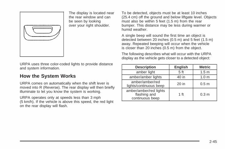
The display is located nearthe rear window and canbe seen by lookingover your right shoulder.
URPA uses three color-coded lights to provide distanceand system information.
How the System WorksURPA comes on automatically when the shift lever ismoved into R (Reverse). The rear display will then brieflyilluminate to let you know the system is working.
URPA operates only at speeds less than 3 mph(5 km/h). If the vehicle is above this speed, the red lighton the rear display will flash.
To be detected, objects must be at least 10 inches(25.4 cm) off the ground and below liftgate level. Objectsmust also be within 5 feet (1.5 m) from the rearbumper. This distance may be less during warmer orhumid weather.
A single beep will sound the first time an object isdetected between 20 inches (0.5 m) and 5 feet (1.5 m)away. Repeated beeping will occur when the vehicleis closer than 20 inches (0.5 m) from the object.
The following describes what will occur with the URPAdisplay as the vehicle gets closer to a detected object:
Description English Metricamber light 5 ft 1.5 m
amber/amber lights 40 in 1.0 mamber/amber/red
lights/continuous beep 20 in 0.5 m
amber/amber/red lightsflashing and
continuous beep1 ft 0.3 m
2-45
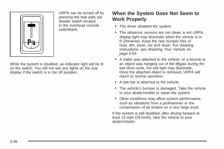
URPA can be turned off bypressing the rear park aiddisable switch locatedin the overhead consoleswitchbank.
While the system is disabled, an indicator light will be liton the switch. You will not see any lights on the reardisplay if the switch is in the off position.
When the System Does Not Seem toWork Properly• The driver disabled the system.
• The ultrasonic sensors are not clean, a red URPAdisplay light may illuminate when the vehicle is inR (Reverse). Keep the rear bumper free ofmud, dirt, snow, ice and slush. For cleaninginstructions, see Washing Your Vehicle onpage 5-93.
• A trailer was attached to the vehicle, or a bicycle oran object was hanging out of the liftgate during thelast drive cycle, the red light may illuminate.Once the attached object is removed, URPA willreturn to normal operation.
• A tow bar is attached to the vehicle.
• The vehicle’s bumper is damaged. Take the vehicleto your dealer/retailer to repair the system.
• Other conditions may affect system performance,such as vibrations from a jackhammer or thecompression of air brakes on a very large truck.
If the system is still disabled, after driving forward atleast 15 mph (25 km/h), take the vehicle to yourdealer/retailer.
2-46
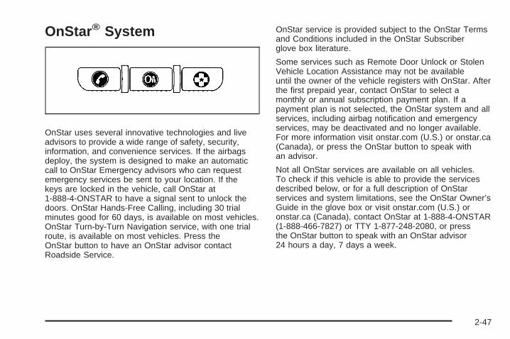
OnStar® System
OnStar uses several innovative technologies and liveadvisors to provide a wide range of safety, security,information, and convenience services. If the airbagsdeploy, the system is designed to make an automaticcall to OnStar Emergency advisors who can requestemergency services be sent to your location. If thekeys are locked in the vehicle, call OnStar at1-888-4-ONSTAR to have a signal sent to unlock thedoors. OnStar Hands-Free Calling, including 30 trialminutes good for 60 days, is available on most vehicles.OnStar Turn-by-Turn Navigation service, with one trialroute, is available on most vehicles. Press theOnStar button to have an OnStar advisor contactRoadside Service.
OnStar service is provided subject to the OnStar Termsand Conditions included in the OnStar Subscriberglove box literature.
Some services such as Remote Door Unlock or StolenVehicle Location Assistance may not be availableuntil the owner of the vehicle registers with OnStar. Afterthe first prepaid year, contact OnStar to select amonthly or annual subscription payment plan. If apayment plan is not selected, the OnStar system and allservices, including airbag notification and emergencyservices, may be deactivated and no longer available.For more information visit onstar.com (U.S.) or onstar.ca(Canada), or press the OnStar button to speak withan advisor.
Not all OnStar services are available on all vehicles.To check if this vehicle is able to provide the servicesdescribed below, or for a full description of OnStarservices and system limitations, see the OnStar Owner’sGuide in the glove box or visit onstar.com (U.S.) oronstar.ca (Canada), contact OnStar at 1-888-4-ONSTAR(1-888-466-7827) or TTY 1-877-248-2080, or pressthe OnStar button to speak with an OnStar advisor24 hours a day, 7 days a week.
2-47
OnStar Services Available with theSafe & Sound Plan• Automatic Notification of Airbag Deployment
• Advanced Automatic Crash Notification (AACN)(If equipped)
• Link to Emergency Services
• Roadside Assistance
• Stolen Vehicle Location Assistance
• Remote Door Unlock/Vehicle Alert
• OnStar Vehicle Diagnostic Email
• GM Goodwrench On Demand Diagnostics
• OnStar Hands-Free Calling with 30 trial minutes
• OnStar Virtual Advisor (U.S. Only)
OnStar Services Included withDirections & Connections Plan• All Safe and Sound Plan Services
• OnStar Turn-by-Turn Navigation (If equipped) orDriving Directions - Advisor delivered
• RideAssist
• Information and Convenience Services
OnStar Hands-Free CallingOnStar Hands-Free Calling allows eligible OnStarsubscribers to make and receive calls using voicecommands. Hands-Free Calling is fully integrated intothe vehicle, and can be used with OnStar Pre-PaidMinute Packages. Most vehicles include 30 trial minutesgood for 60 days. Hands-Free Calling can also belinked to a Verizon Wireless service plan in the U.S. ora Bell Mobility service plan in Canada, dependingon eligibility. To find out more, refer to the OnStarOwner’s Guide in the vehicle’s glove box, visitonstar.com or onstar.ca, or speak with an OnStaradvisor by pressing the OnStar button or calling1-888-4-ONSTAR (1-888-466-7827).
OnStar Turn-by-Turn NavigationVehicles with the OnStar Turn-by-Turn Navigationsystem can provide voice-guided driving directions.Press the OnStar button to have an OnStar advisorlocate a business or address and download drivingdirections to the vehicle. Voice-guided directions to thedesired destination will play through the audio systemspeakers. See the OnStar Owner’s Guide for moreinformation.
2-48
OnStar Virtual AdvisorOnStar Virtual Advisor is a feature of OnStarHands-Free Calling that uses minutes to accesslocation-based weather, local traffic reports, andstock quotes. Press the phone button and give afew simple voice commands to browse through thevarious topics. See the OnStar Owner’s Guide formore information. This feature is only available in thecontinental U.S.
OnStar Steering Wheel ControlsThis vehicle may have a Talk/Mute button that canbe used to interact with OnStar Hands-Free Calling. SeeAudio Steering Wheel Controls on page 3-111 formore information.
On some vehicles, the mute button can be used to dialnumbers into voice mail systems, or to dial phoneextensions. See the OnStar Owner’s Guide for moreinformation.
How OnStar Service WorksThe OnStar system can record and transmit vehicleinformation. This information is automatically sent to anOnStar Call Center when the OnStar button ispressed, the emergency button is pressed, or if theairbags or AACN system deploy. This informationusually includes the vehicle’s GPS location and, in theevent of a crash, additional information regardingthe crash that the vehicle was involved in (e.g. thedirection from which the vehicle was hit). Whenthe Virtual Advisor feature of OnStar Hands-Free Callingis used, the vehicle also sends OnStar the vehicle’sGPS location so they can provide services where it islocated.
OnStar service cannot work unless the vehicle is in aplace where OnStar has an agreement with a wirelessservice provider for service in that area. OnStar servicealso cannot work unless the vehicle is in a place wherethe wireless service provider OnStar has hired for thatarea has coverage, network capacity and reception whenthe service is needed, and technology that is compatiblewith the OnStar service. Not all services are availableeverywhere, particularly in remote or enclosed areas, orat all times.
2-49
Location information about the vehicle is only availableif the GPS satellite signals are unobstructed andavailable.
The vehicle must have a working electrical system,including adequate battery power, for the OnStarequipment to operate. There are other problems OnStarcannot control that may prevent OnStar from providingOnStar service at any particular time or place. Someexamples are damage to important parts of the vehiclein a crash, hills, tall buildings, tunnels, weather orwireless phone network congestion.
Your ResponsibilityIncrease the volume of the radio if the OnStar advisorcannot be heard. If the light next to the OnStar buttonsis red, the system may not be functioning properly.Press the OnStar button and request a vehiclediagnostic. If the light appears clear (no light isappearing), your OnStar subscription has expired andall services have been deactivated. Press the OnStarbutton to confirm that the OnStar equipment is active.
Universal Home RemoteSystemThe Universal Home Remote System provides a way toreplace up to three hand-held Radio-Frequency (RF)transmitters used to activate devices such as garagedoor openers, security systems, and home lighting.
This device complies with Part 15 of the FCC Rules.Operation is subject to the following two conditions:
1. This device may not cause harmful interference.
2. This device must accept any interference received,including interference that may cause undesiredoperation.
This device complies with RSS-210 of Industry Canada.Operation is subject to the following two conditions:
1. This device may not cause interference.
2. This device must accept any interference received,including interference that may cause undesiredoperation of the device.
Changes or modifications to this system by other thanan authorized service facility could void authorization touse this equipment.
2-50
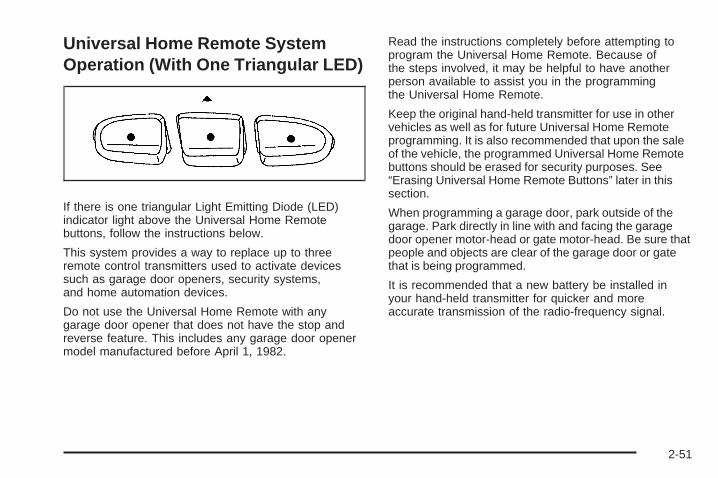
Universal Home Remote SystemOperation (With One Triangular LED)
If there is one triangular Light Emitting Diode (LED)indicator light above the Universal Home Remotebuttons, follow the instructions below.
This system provides a way to replace up to threeremote control transmitters used to activate devicessuch as garage door openers, security systems,and home automation devices.
Do not use the Universal Home Remote with anygarage door opener that does not have the stop andreverse feature. This includes any garage door openermodel manufactured before April 1, 1982.
Read the instructions completely before attempting toprogram the Universal Home Remote. Because ofthe steps involved, it may be helpful to have anotherperson available to assist you in the programmingthe Universal Home Remote.
Keep the original hand-held transmitter for use in othervehicles as well as for future Universal Home Remoteprogramming. It is also recommended that upon the saleof the vehicle, the programmed Universal Home Remotebuttons should be erased for security purposes. See“Erasing Universal Home Remote Buttons” later in thissection.
When programming a garage door, park outside of thegarage. Park directly in line with and facing the garagedoor opener motor-head or gate motor-head. Be sure thatpeople and objects are clear of the garage door or gatethat is being programmed.
It is recommended that a new battery be installed inyour hand-held transmitter for quicker and moreaccurate transmission of the radio-frequency signal.
2-51
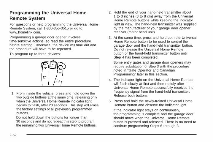
Programming the Universal HomeRemote SystemFor questions or help programming the Universal HomeRemote System, call 1-800-355-3515 or go towww.homelink.com.Programming a garage door opener involvestime-sensitive actions, so read the entire procedurebefore starting. Otherwise, the device will time out andthe procedure will have to be repeated.To program up to three devices:
1. From inside the vehicle, press and hold down thetwo outside buttons at the same time, releasing onlywhen the Universal Home Remote indicator lightbegins to flash, after 20 seconds. This step will erasethe factory settings or all previously programmedbuttons.Do not hold down the buttons for longer than30 seconds and do not repeat this step to programthe remaining two Universal Home Remote buttons.
2. Hold the end of your hand-held transmitter about1 to 3 inches (3 to 8 cm) away from the UniversalHome Remote buttons while keeping the indicatorlight in view. The hand-held transmitter was suppliedby the manufacturer of your garage door openerreceiver (motor head unit).
3. At the same time, press and hold both the UniversalHome Remote button to be used to control thegarage door and the hand-held transmitter button.Do not release the Universal Home Remotebutton or the hand-held transmitter button untilStep 4 has been completed.Some entry gates and garage door openers mayrequire substitution of Step 3 with the procedurenoted in “Gate Operator and CanadianProgramming” later in this section.
4. The indicator light on the Universal Home Remotewill flash slowly at first and then rapidly afterUniversal Home Remote successfully receives thefrequency signal from the hand-held transmitter.Release both buttons.
5. Press and hold the newly-trained Universal HomeRemote button and observe the indicator light.If the indicator light stays on continuously,the programming is complete and the garage doorshould move when the Universal Home Remotebutton is pressed and released. There is no need tocontinue programming Steps 6 through 8.
2-52
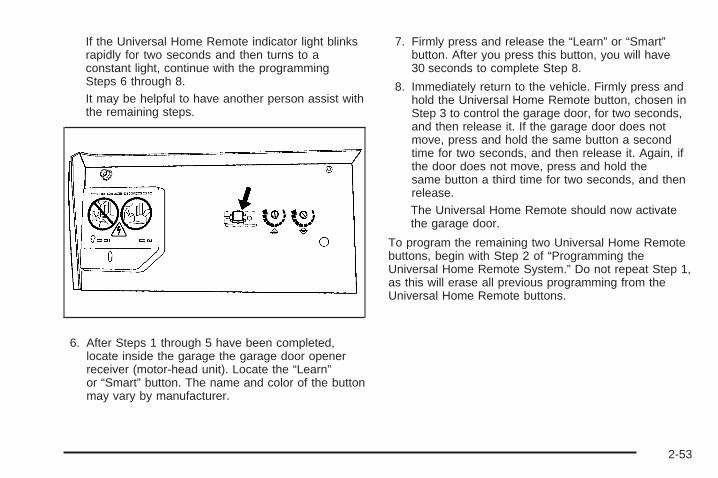
If the Universal Home Remote indicator light blinksrapidly for two seconds and then turns to aconstant light, continue with the programmingSteps 6 through 8.It may be helpful to have another person assist withthe remaining steps.
6. After Steps 1 through 5 have been completed,locate inside the garage the garage door openerreceiver (motor-head unit). Locate the “Learn”or “Smart” button. The name and color of the buttonmay vary by manufacturer.
7. Firmly press and release the “Learn” or “Smart”button. After you press this button, you will have30 seconds to complete Step 8.
8. Immediately return to the vehicle. Firmly press andhold the Universal Home Remote button, chosen inStep 3 to control the garage door, for two seconds,and then release it. If the garage door does notmove, press and hold the same button a secondtime for two seconds, and then release it. Again, ifthe door does not move, press and hold thesame button a third time for two seconds, and thenrelease.The Universal Home Remote should now activatethe garage door.
To program the remaining two Universal Home Remotebuttons, begin with Step 2 of “Programming theUniversal Home Remote System.” Do not repeat Step 1,as this will erase all previous programming from theUniversal Home Remote buttons.
2-53
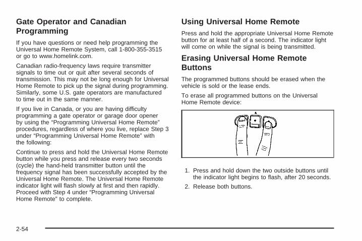
Gate Operator and CanadianProgrammingIf you have questions or need help programming theUniversal Home Remote System, call 1-800-355-3515or go to www.homelink.com.
Canadian radio-frequency laws require transmittersignals to time out or quit after several seconds oftransmission. This may not be long enough for UniversalHome Remote to pick up the signal during programming.Similarly, some U.S. gate operators are manufacturedto time out in the same manner.
If you live in Canada, or you are having difficultyprogramming a gate operator or garage door openerby using the “Programming Universal Home Remote”procedures, regardless of where you live, replace Step 3under “Programming Universal Home Remote” withthe following:
Continue to press and hold the Universal Home Remotebutton while you press and release every two seconds(cycle) the hand-held transmitter button until thefrequency signal has been successfully accepted by theUniversal Home Remote. The Universal Home Remoteindicator light will flash slowly at first and then rapidly.Proceed with Step 4 under “Programming UniversalHome Remote” to complete.
Using Universal Home RemotePress and hold the appropriate Universal Home Remotebutton for at least half of a second. The indicator lightwill come on while the signal is being transmitted.
Erasing Universal Home RemoteButtonsThe programmed buttons should be erased when thevehicle is sold or the lease ends.
To erase all programmed buttons on the UniversalHome Remote device:
1. Press and hold down the two outside buttons untilthe indicator light begins to flash, after 20 seconds.
2. Release both buttons.
2-54
Reprogramming a Single UniversalHome Remote ButtonTo reprogram any of the three Universal Home Remotebuttons, repeat the programming instructions earlierin this section, beginning with Step 2.
For help or information on the Universal Home RemoteSystem, call the customer assistance phone numberunder Customer Assistance Offices on page 7-6.
Storage AreasYour vehicle’s large carrying capacity can store manyitems. If the vehicle has an extended wheelbase, it cancarry even larger items. The floor pins that are usedto attach the seats, can be used to secure larger loads.
Glove BoxLift the glovebox handle up to open it. Use the key tolock and unlock the glovebox.
CupholdersThere are cupholders located below the centerinstrument panel switchbank. The cupholders have arubber liner that can be removed, so that larger cups canfit into the cupholders. You can also remove the linerto clean it.
To use the cupholders, pull the tray out. Push the trayback when not in use.
Your vehicle may be equipped with cupholders in thesecond row.
Overhead Console (Without Rail)If your vehicle has an overhead console without the railsystem, it has two reading lights, a courtesy light,and a switchbank. See Overhead Console Switchbankon page 3-19 for more information.
2-55
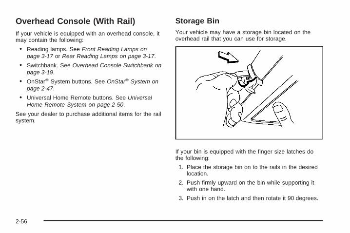
Overhead Console (With Rail)If your vehicle is equipped with an overhead console, itmay contain the following:
• Reading lamps. See Front Reading Lamps onpage 3-17 or Rear Reading Lamps on page 3-17.
• Switchbank. See Overhead Console Switchbank onpage 3-19.
• OnStar® System buttons. See OnStar® System onpage 2-47.
• Universal Home Remote buttons. See UniversalHome Remote System on page 2-50.
See your dealer to purchase additional items for the railsystem.
Storage BinYour vehicle may have a storage bin located on theoverhead rail that you can use for storage.
If your bin is equipped with the finger size latches dothe following:
1. Place the storage bin on to the rails in the desiredlocation.
2. Push firmly upward on the bin while supporting itwith one hand.
3. Push in on the latch and then rotate it 90 degrees.
2-56
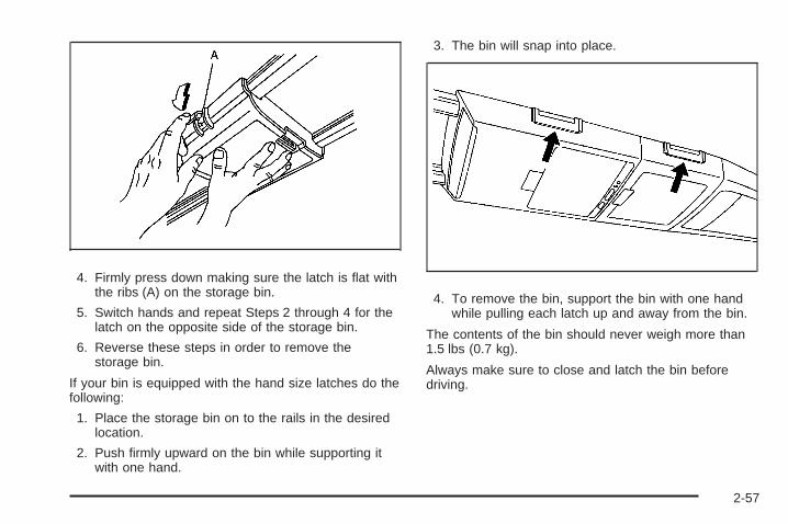
4. Firmly press down making sure the latch is flat withthe ribs (A) on the storage bin.
5. Switch hands and repeat Steps 2 through 4 for thelatch on the opposite side of the storage bin.
6. Reverse these steps in order to remove thestorage bin.
If your bin is equipped with the hand size latches do thefollowing:
1. Place the storage bin on to the rails in the desiredlocation.
2. Push firmly upward on the bin while supporting itwith one hand.
3. The bin will snap into place.
4. To remove the bin, support the bin with one handwhile pulling each latch up and away from the bin.
The contents of the bin should never weigh more than1.5 lbs (0.7 kg).
Always make sure to close and latch the bin beforedriving.
2-57
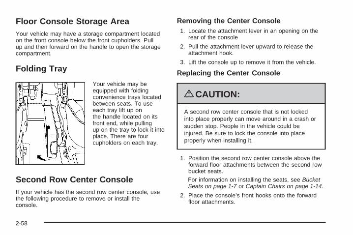
Floor Console Storage AreaYour vehicle may have a storage compartment locatedon the front console below the front cupholders. Pullup and then forward on the handle to open the storagecompartment.
Folding Tray
Your vehicle may beequipped with foldingconvenience trays locatedbetween seats. To useeach tray lift up onthe handle located on itsfront end, while pullingup on the tray to lock it intoplace. There are fourcupholders on each tray.
Second Row Center ConsoleIf your vehicle has the second row center console, usethe following procedure to remove or install theconsole.
Removing the Center Console1. Locate the attachment lever in an opening on the
rear of the console
2. Pull the attachment lever upward to release theattachment hook.
3. Lift the console up to remove it from the vehicle.
Replacing the Center Console
{CAUTION:
A second row center console that is not lockedinto place properly can move around in a crash orsudden stop. People in the vehicle could beinjured. Be sure to lock the console into placeproperly when installing it.
1. Position the second row center console above theforward floor attachments between the second rowbucket seats.For information on installing the seats, see BucketSeats on page 1-7 or Captain Chairs on page 1-14.
2. Place the console’s front hooks onto the forwardfloor attachments.
2-58
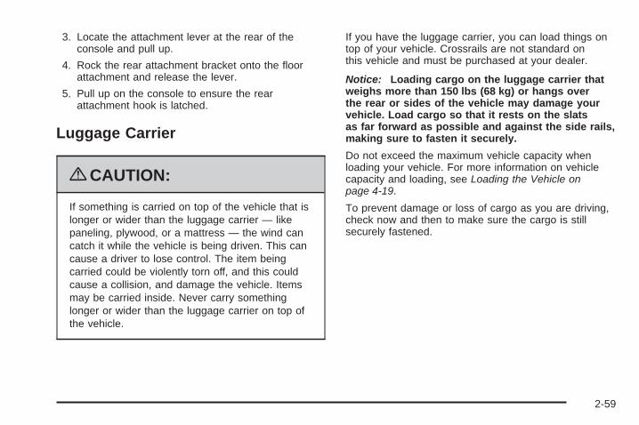
3. Locate the attachment lever at the rear of theconsole and pull up.
4. Rock the rear attachment bracket onto the floorattachment and release the lever.
5. Pull up on the console to ensure the rearattachment hook is latched.
Luggage Carrier
{CAUTION:
If something is carried on top of the vehicle that islonger or wider than the luggage carrier — likepaneling, plywood, or a mattress — the wind cancatch it while the vehicle is being driven. This cancause a driver to lose control. The item beingcarried could be violently torn off, and this couldcause a collision, and damage the vehicle. Itemsmay be carried inside. Never carry somethinglonger or wider than the luggage carrier on top ofthe vehicle.
If you have the luggage carrier, you can load things ontop of your vehicle. Crossrails are not standard onthis vehicle and must be purchased at your dealer.
Notice: Loading cargo on the luggage carrier thatweighs more than 150 lbs (68 kg) or hangs overthe rear or sides of the vehicle may damage yourvehicle. Load cargo so that it rests on the slatsas far forward as possible and against the side rails,making sure to fasten it securely.
Do not exceed the maximum vehicle capacity whenloading your vehicle. For more information on vehiclecapacity and loading, see Loading the Vehicle onpage 4-19.
To prevent damage or loss of cargo as you are driving,check now and then to make sure the cargo is stillsecurely fastened.
2-59
Convenience Net (With RearConvenience Center)Your vehicle may have a convenience net. Theconvenience net is designed to help keep small loads,from falling out of the vehicle when the liftgate isopened. Install the convenience net at the rear of yourvehicle, inside the liftgate.
To use the convenience net, do the following:
1. Attach the upper loops to the posts on both sides ofthe liftgate opening. The label on the net should bein the upper left corner.
2. Attach the lower loops to the tabs at the rear edgeof the rear convenience center.
When not in use, it is recommended that you take downthe convenience net to extend the life of the net andto help retain its elasticity, and to keep the rearexit clear.
Convenience Net (Without RearConvenience Center)Your vehicle may have a convenience net. Theconvenience net is designed to help keep small loads,like grocery bags, from falling over. Install theconvenience net at the rear of your vehicle, inside theliftgate.
To use the convenience net, do the following:
1. Attach the upper loops to the posts on both sides ofthe liftgate opening. The label on the net should bein the upper left corner.
2. Attach the lower hooks to the metal rings onthe floor.
3. Once you have loaded items into the net, stretchthe higher side of the net up and over the top ofthe load to hold it firmly in place.
The convenience net has a maximum capacity of100 lbs (45 kg). It is not designed to hold larger, heavierloads. Store such loads on the floor of your vehicle,as far forward as you can.
When not in use, it is recommended that you take downthe convenience net to extend the life of the net andto help retain its elasticity, and to keep the rearexit clear.
2-60

Convenience Center
{CAUTION:
If any removable convenience item is not securedproperly, it can move around in a collision orsudden stop. People in the vehicle could beinjured. Be sure to secure any such item properly.
Your vehicle may have a convenience center. It providesextra storage space for the rear of the vehicle.
To open the convenience center, pull up on the doorlatch located on the front of the cover. The conveniencecenter cover has two automatic prop rods to hold itup and in place.
To close the convenience center cover, you must pullone of the prop rod linkages toward you while holdingonto the door latch and lower the conveniencecenter cover to close it.
Removing the Convenience Center1. Make sure that all items are off the convenience
center and that it is empty.
2. Turn the hand knob, located at the rear of theconvenience center, counterclockwise until theknob is loose.
3. Lift up on the hand knob, then grip and pull up onthe convenience center to remove it from thevehicle.
2-61
Replacing the Convenience Center1. Make sure the third row seat is properly installed in
the vehicle. See Third Row Seat on page 1-18 formore information. If the third row seat is not inthe vehicle with the convenience center, theconvenience center will not be locked into thecorrect position in the vehicle.
2. Make sure that the convenience center is emptyand closed.
3. Lift the convenience center up and into the rear ofthe vehicle.
4. Slide the convenience center in and align it to therear seat.
5. Press down on the front of the convenience centerso the center is aligned on the sill mountingbracket.
6. Turn the hand knob clockwise until it is tight.
7. Pull up on the convenience center to make sure itis locked into place.
The cover of the convenience center can be left in itsupright position while the vehicle is moving.
The convenience center and the third row seat bothhave a maximum weight capacity of 400 lbs (181.6 kg).
Notice: Overloading your vehicle may causedamage. Repairs would not be covered by yourwarranty. Do not overload your vehicle.
2-62
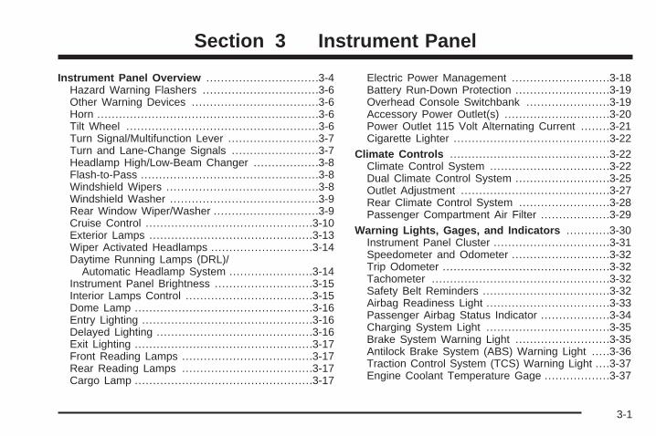
Instrument Panel Overview ...............................3-4Hazard Warning Flashers ................................3-6Other Warning Devices ...................................3-6Horn .............................................................3-6Tilt Wheel .....................................................3-6Turn Signal/Multifunction Lever .........................3-7Turn and Lane-Change Signals ........................3-7Headlamp High/Low-Beam Changer ..................3-8Flash-to-Pass .................................................3-8Windshield Wipers ..........................................3-8Windshield Washer .........................................3-9Rear Window Wiper/Washer .............................3-9Cruise Control ..............................................3-10Exterior Lamps .............................................3-13Wiper Activated Headlamps ............................3-14Daytime Running Lamps (DRL)/
Automatic Headlamp System .......................3-14Instrument Panel Brightness ...........................3-15Interior Lamps Control ...................................3-15Dome Lamp .................................................3-16Entry Lighting ...............................................3-16Delayed Lighting ...........................................3-16Exit Lighting .................................................3-17Front Reading Lamps ....................................3-17Rear Reading Lamps ....................................3-17Cargo Lamp .................................................3-17
Electric Power Management ...........................3-18Battery Run-Down Protection ..........................3-19Overhead Console Switchbank .......................3-19Accessory Power Outlet(s) .............................3-20Power Outlet 115 Volt Alternating Current ........3-21Cigarette Lighter ...........................................3-22
Climate Controls ............................................3-22Climate Control System .................................3-22Dual Climate Control System ..........................3-25Outlet Adjustment .........................................3-27Rear Climate Control System .........................3-28Passenger Compartment Air Filter ...................3-29
Warning Lights, Gages, and Indicators ............3-30Instrument Panel Cluster ................................3-31Speedometer and Odometer ...........................3-32Trip Odometer ..............................................3-32Tachometer .................................................3-32Safety Belt Reminders ...................................3-32Airbag Readiness Light ..................................3-33Passenger Airbag Status Indicator ...................3-34Charging System Light ..................................3-35Brake System Warning Light ..........................3-35Antilock Brake System (ABS) Warning Light .....3-36Traction Control System (TCS) Warning Light ....3-37Engine Coolant Temperature Gage ..................3-37
Section 3 Instrument Panel
3-1
Tire Pressure Light .......................................3-38Malfunction Indicator Lamp .............................3-38Oil Pressure Light .........................................3-41Security Light ...............................................3-41Cruise Control Light ......................................3-42Highbeam On Light .......................................3-42Fuel Gage ...................................................3-42Low Fuel Warning Light .................................3-43
Driver Information Center (DIC) .......................3-43DIC Operation and Displays ...........................3-44DIC Compass (Uplevel Only) ..........................3-49DIC Warnings and Messages .........................3-51DIC Vehicle Personalization (Uplevel Only) .......3-68
Audio System(s) .............................................3-76Setting the Clock ..........................................3-77Radio(s) (MP3) .............................................3-77Using an MP3 ..............................................3-89XM Radio Messages .....................................3-92Rear Seat Entertainment (RSE) System ...........3-93Rear Seat Audio (RSA) ................................3-108Theft-Deterrent Feature ................................3-110Audio Steering Wheel Controls ......................3-111Radio Reception .........................................3-112Fixed Mast Antenna ....................................3-113XM™ Satellite Radio Antenna System ............3-113Chime Level Adjustment ...............................3-113
Section 3 Instrument Panel
3-2

✍ NOTES
3-3
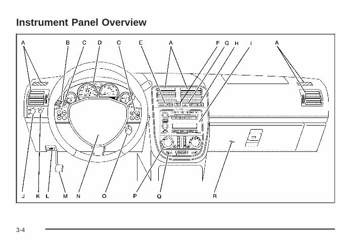
Instrument Panel Overview
3-4
The main components of the instrument panel are the following:
A. Outlet Adjustment on page 3-27.B. Turn Signal/Multifunction Lever on page 3-7.C. Audio Steering Wheel Controls on page 3-111
(If Equipped).D. Instrument Panel Cluster on page 3-31.E. Driver Information Center (DIC) on page 3-43
(If Equipped).F. Traction Control System (TCS) on page 4-6
(If Equipped).G. Hazard Warning Flashers on page 3-6.H. Passenger Airbag Status Indicator on page 3-34
and Safety Belt Reminders on page 3-32.I. Audio System(s) on page 3-76.
J. Exterior Lamps on page 3-13.K. Interior Lamps Control on page 3-15. Instrument
Panel Brightness on page 3-15.L. Hood Release on page 5-13.M. Parking Brake on page 2-38.N. Horn on page 3-6.O. Cruise Control on page 3-10 (If Equipped).P. Climate Control System on page 3-22. Dual Climate
Control System on page 3-25.Q. Heated Seats on page 1-3 (If Equipped).R. Glove Box on page 2-55.
3-5
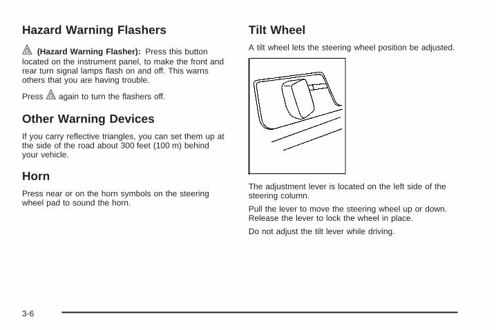
Hazard Warning Flashers
| (Hazard Warning Flasher): Press this buttonlocated on the instrument panel, to make the front andrear turn signal lamps flash on and off. This warnsothers that you are having trouble.
Press | again to turn the flashers off.
Other Warning DevicesIf you carry reflective triangles, you can set them up atthe side of the road about 300 feet (100 m) behindyour vehicle.
HornPress near or on the horn symbols on the steeringwheel pad to sound the horn.
Tilt WheelA tilt wheel lets the steering wheel position be adjusted.
The adjustment lever is located on the left side of thesteering column.
Pull the lever to move the steering wheel up or down.Release the lever to lock the wheel in place.
Do not adjust the tilt lever while driving.
3-6
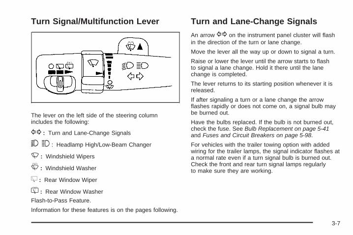
Turn Signal/Multifunction Lever
The lever on the left side of the steering columnincludes the following:
G : Turn and Lane-Change Signals
5 3 : Headlamp High/Low-Beam Changer
N : Windshield Wipers
L : Windshield Washer
Z : Rear Window Wiper
= : Rear Window Washer
Flash-to-Pass Feature.
Information for these features is on the pages following.
Turn and Lane-Change Signals
An arrow G on the instrument panel cluster will flashin the direction of the turn or lane change.
Move the lever all the way up or down to signal a turn.
Raise or lower the lever until the arrow starts to flashto signal a lane change. Hold it there until the lanechange is completed.
The lever returns to its starting position whenever it isreleased.
If after signaling a turn or a lane change the arrowflashes rapidly or does not come on, a signal bulb maybe burned out.
Have the bulbs replaced. If the bulb is not burned out,check the fuse. See Bulb Replacement on page 5-41and Fuses and Circuit Breakers on page 5-98.
For vehicles with the trailer towing option with addedwiring for the trailer lamps, the signal indicator flashes ata normal rate even if a turn signal bulb is burned out.Check the front and rear turn signal lamps regularlyto make sure they are working.
3-7
Turn Signal On ChimeIf either turn signal is left on for more than 3/4 mile(1.2 km), a chime sounds to let the driver know to turn itoff. If the signal needs to be left on for more than 3/4 mile(1.2 km), turn the signal off and then turn it back on.
Headlamp High/Low-Beam ChangerThe headlamps must be on for this feature to work.
Push the turn signal lever away from you to turn the highbeams on.
This instrument panel cluster light 3 comes on whilethe high beam headlamps are on.
Pull the lever towards you to return to low beams.
Flash-to-PassThis feature is used to signal the vehicle ahead that youwant to pass. When the headlamps are off, pull thelever toward you to momentarily turn on the high beams.Release the lever, to turn the high beams off.
Windshield WipersThe windshield wiper/washer switch is on themultifunction lever located on the left side of thesteering column.
Turn the band with N on it to control the wipers.
8 (Mist): Turn to mist, for a single wiping cycle andthen release. The wipers stop after one wipe. Holdlonger for additional wipes.
9 (Off): Move the band to this position to turn thewipers off.
N (Delay): Turn the band to choose the delay timebetween wipes. Turn towards the top or bottom ofthe lever, for a shorter or longer delay.
6 (Low Speed): Use for steady wiping at lowspeed.
1 (High Speed): Use for steady wiping at highspeed.
Be sure to clear ice and snow from the wiper bladesbefore using them. If they are frozen to the windshield,carefully loosen or thaw them. If your blades do becomeworn or damaged, get new blades or blade inserts.
3-8
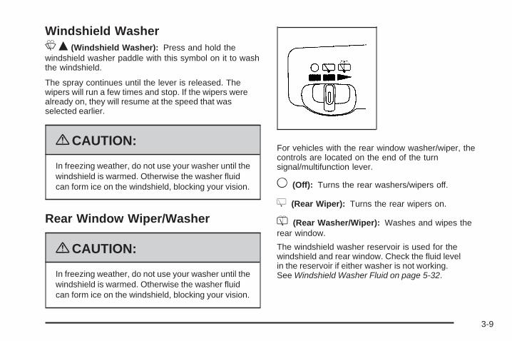
Windshield WasherLQ (Windshield Washer): Press and hold thewindshield washer paddle with this symbol on it to washthe windshield.
The spray continues until the lever is released. Thewipers will run a few times and stop. If the wipers werealready on, they will resume at the speed that wasselected earlier.
{CAUTION:
In freezing weather, do not use your washer until thewindshield is warmed. Otherwise the washer fluidcan form ice on the windshield, blocking your vision.
Rear Window Wiper/Washer
{CAUTION:
In freezing weather, do not use your washer until thewindshield is warmed. Otherwise the washer fluidcan form ice on the windshield, blocking your vision.
For vehicles with the rear window washer/wiper, thecontrols are located on the end of the turnsignal/multifunction lever.
9 (Off): Turns the rear washers/wipers off.
Z (Rear Wiper): Turns the rear wipers on.
= (Rear Washer/Wiper): Washes and wipes therear window.
The windshield washer reservoir is used for thewindshield and rear window. Check the fluid levelin the reservoir if either washer is not working.See Windshield Washer Fluid on page 5-32.
3-9
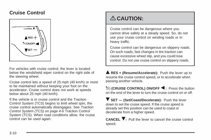
Cruise Control
For vehicles with cruise control, the lever is locatedbelow the windshield wiper control on the right side ofthe steering wheel.
Cruise control lets a speed of 25 mph (40 km/h) or moreto be maintained without keeping your foot on theaccelerator. Cruise control does not work at speedsbelow about 25 mph (40 km/h).
If the vehicle is in cruise control and the TractionControl System (TCS) begins to limit wheel spin, thecruise control automatically disengages. See TractionControl System (TCS) on page 4-6 Traction ControlSystem (TCS). When road conditions allow, the cruisecontrol can be used again.
{CAUTION:
Cruise control can be dangerous where youcannot drive safely at a steady speed. So, do notuse your cruise control on winding roads or inheavy traffic.
Cruise control can be dangerous on slippery roads.On such roads, fast changes in tire traction cancause excessive wheel slip, and you could losecontrol. Do not use cruise control on slippery roads.
Q RES + (Resume/Accelerate): Push the lever up toresume the cruise control speed, or to accelerate whenpassing another vehicle.
J (CRUISE CONTROL) ON/OFF q : Press the buttonon the end of the lever to turn the cruise control on or off.
R SET — (Set/Coast/Decelerate): Push the leverdown to set the cruise speed. If the cruise speed isalready set this position can be used to coast ordecelerate from a higher speed.
CANCEL R: Pull the lever to cancel the cruise controlspeed.
3-10
Setting Cruise Control
{CAUTION:
If you leave your cruise control on when you arenot using cruise, you might hit a button and gointo cruise when you do not want to. You could bestartled and even lose control. Keep the cruisecontrol switch off until you want to use cruisecontrol.
1. Push I at the end of the cruise control lever toturn the cruise control on.
2. Accelerate to the desired speed.
3. Push down on R SET — and release it. This setsthe speed in cruise control.
4. Remove your foot from the accelerator pedal.
J appears on the instrument panel cluster when thecruise control is set. This symbol disappears whenthe brakes are applied or the cruise control is cancelled.It will reappear when the set cruise speed is resumed.
Resuming a Set SpeedIf the brakes are applied after the cruise control is set,the cruise control is disengaged. But the cruise controldoes not need to be reset.
Once the vehicle is speed is 25 mph (40 km/h) orgreater, push the lever up toward the Q RES + positionto return to the previously set speed.
Do not continue to hold the lever in the Q RES +position, unless a faster speed is desired.
Increasing Speed While Using CruiseControlThere are two ways to go to a higher speed:
• Use the accelerator pedal to get to the higherspeed. Push the lever up toward Q RES +,then release the lever and the accelerator pedal.
• Push the lever up to Q RES +. Hold it there untilthe vehicle reaches the desired speed, and thenrelease the lever. To increase the vehicle speed invery small amounts, push up briefly on the leverand release it. Each time this is done, the vehiclegoes about 1 mph (1.6 km/h) faster.
The acceleration feature only works after the cruisecontrol speed has been set by pushing the cruise controllever to the R SET — position.
3-11
Reducing Speed While Using CruiseControlThere are two ways to reduce the vehicle’s speed whileusing cruise control:
• Push the lever toward the R SET — until a lowerspeed is reached, then release it.
• To slow down in very small amounts, push the levertoward R SET — briefly. Each time this is done,the vehicle goes about 1 mph (1.6 km/h) slower.
Passing Another Vehicle While UsingCruise ControlUse the accelerator pedal to increase the vehicle speed.When you take your foot off the pedal, the vehicleslows down to the cruise control speed set earlier.
Using Cruise Control on HillsThe cruise control performance will vary dependingupon the vehicle speed, load, and the steepness of thehills. When going up steep hills, you might have tostep on the accelerator pedal to maintain the vehiclespeed. When going downhill, you might have to brake orshift to a lower gear to keep the vehicle speed down.This turns off the cruise control.
Ending Cruise ControlPull the cruise control lever forward or step lightly onthe brake pedal, to disengage the cruise control. The setspeed will be retained in memory.
Push I at the end of the lever to turn the cruisecontrol system off.
Erasing Speed MemoryThe cruise control set speed memory is erased whenthe cruise control or the ignition is turned off.
3-12

Exterior Lamps
The exterior lamps control is located on the instrumentpanel to the left of the steering wheel.
9 (Off): Turns all the lamps off. This is a momentarycontrol that springs back to AUTO when released.
The automatic headlamps and/or the Daytime RunningLamps can be turned on and off for U.S. vehicles.For vehicles first sold in Canada, the transmissionmust be in the P (Park) position.
AUTO (Automatic): Turns the exterior lamps on andoff automatically.
The automatic lights can be disabled even if the controlis in the AUTO position.
; (Parking Lamps): Turns on the parking lampstogether with the following:
• Taillamps
• Instrument Panel Lights
5 (Headlamps): Turns on the headlamps togetherwith the following:
• Parking Lamps
• Taillamps
• Instrument Panel Lights
Headlamps on ReminderA warning chime sounds if the driver door is openedwhile the ignition is turned to LOCK/OFF and theexterior lamps are on.
3-13
Wiper Activated HeadlampsFor vehicles with this feature, the headlamps andparking lamps are automatically activated after thewindshield wipers have been in use for about 30 secondsand when all of the following conditions are met.
• The exterior lamp control is in AUTO.
• The headlamps have not already been activated byautomatic lighting.
• The automatic lighting feature has not been disabledusing the exterior lamp control.
See Exterior Lamps on page 3-13 for additionalinformation.
If the wipers are activated for over 30 seconds and theexterior lamp control is in the parking lamps position, orthe automatic lighting feature has been disabled usingthe exterior lamp control, a HEADLAMPS SUGGESTEDmessage appears on the Driver Information Center, ifequipped.
Daytime Running Lamps (DRL)/Automatic Headlamp SystemDaytime Running Lamps (DRL) can make it easier forothers to see the front of your vehicle during theday. Fully functional Daytime Running Lamps arerequired on all vehicles first sold in Canada.A light sensor on top of the instrument panel makes theDRL work, so be sure it is not covered. The DRLsystem makes the front turn signal lamps come on indaylight when the following conditions are met:
• The ignition is on.
• The exterior lamps control is off.
When the DRL are on, only the front turn signal lampswill be on. The instrument panel will not be lit up.The exterior lamps automatically switch from DRL toregular headlamps depending on the darkness ofthe surroundings.If vehicle is started in a dark garage, the automaticheadlamp system comes on immediately. Once thevehicle leaves the garage, it takes approximately30 seconds for the automatic headlamp system tochange to DRL if it is light outside. During that delay, theinstrument panel cluster may not be as bright as usual.Make sure the instrument panel brightness control is inthe full bright position. See Instrument Panel Brightnesson page 3-15.
3-14
To idle the vehicle with the DRL and automaticheadlamps off, toggle the exterior lamp controlto off after starting the vehicle.
The regular headlamp system should be turned onwhen needed.
Instrument Panel Brightness
The instrument panel brightness knob is located in thecenter of the interior lamp controls.
Turn the knob clockwise or counterclockwise to brightenor dim the lights.
Interior Lamps Control
The interior lamp control is located on the instrumentpanel to the left of the steering column.
Turn the outer knob to control the interior lamps.
R (Interior Lamp Override): The interior lampsremain off while any door is open.
1 (Door): Turns the interior lamps on while any dooris open and when the ignition key is removed fromthe ignition.
+ (Interior Lamps): Turns the interior lamps on.
The inner knob adjusts the instrument panel brightness,described earlier in this section.
3-15
Dome LampThe dome lamp is located in the headliner and has twobuttons to manually turn it on or off. The dome lampcomes on each time a door is opened, unless the interiorlamps override feature is turned on. See InteriorLamps Control on page 3-15.
Entry LightingThe interior lights come on if the door is unlocked usingthe key or remote keyless entry transmitter and theignition is in LOCK/OFF. The lights remain on for about20 seconds and then goes out, except under thefollowing conditions:
• All the doors are locked using the key.
• The lock is pressed on the power door lock switch.
• The lock is pressed on the remote keyless entrytransmitter.
The interior lights stay on while any door or the liftgateis open, and go out when all doors and the liftgateare closed. The entry lighting is cancelled when anydoor is opened.
The lights may stay on for up to 25 seconds after alldoors have been closed if they have not been locked.See Delayed Lighting on page 3-16.
To turn the entry lighting feature off or on, see DICVehicle Personalization (Uplevel Only) on page 3-68.
Delayed LightingThe delayed lighting feature lights the interior for20 seconds after all doors have been closed. Delayedlighting will not occur while the ignition is in ON/RUN orACC/ACCESSORY. The interior lights remain on forabout 20 seconds and then goes out, except under thefollowing conditions:
• The ignition is turned to ON/RUN orACC/ACCESSORY.
• All doors are locked using the remote keyless entrytransmitter.
• All doors are locked using the power door lockswitch or the key.
To turn the delayed lighting feature off or on, see DICVehicle Personalization (Uplevel Only) on page 3-68.
3-16
Exit LightingThe interior lights come on for about 25 secondswhenever the key is removed from the ignition. If theignition key is turned to ON/RUN or ACC/ACCESSORY,the lights fade out. The lights also fade out if the doorsare locked with the power door lock switch or the remotekeyless entry transmitter.
Exit lighting is cancelled when any door is opened.The interior lights stay on while any door or the liftgateis open, and go out when all doors and the liftgateare closed.
The interior lights may stay on for up to 20 secondsafter all doors have been closed if they have not beenlocked. See Delayed Lighting on page 3-16.
To turn the exit lighting feature off or on, see DICVehicle Personalization (Uplevel Only) on page 3-68.
Front Reading LampsThere are two reading lamps and one courtesy lamp inthe overhead console. Press either lamp to turn eachon or off. The courtesy lamp comes on each time a dooris opened, unless the interior lamps override featureis turned on. See Interior Lamps Control on page 3-15.
Rear Reading LampsThere are two reading lamps in the third row headliner.Press either lamp to turn each on or off.
There may also be a reading lamp in the second row,integrated with the dome lamp. Press the button next tothe lamp lens to turn the second row reading lampon or off.
Cargo LampThe cargo lamp is located in the rear of the vehicle,above the liftgate opening, and does not have a switch.The cargo lamp comes on each time a door isopened, unless the interior lamps override is turned on.See Interior Lamps Control on page 3-15.
3-17
Electric Power ManagementThe vehicle has Electric Power Management (EPM)that estimates the battery’s temperature and stateof charge. It then adjusts the voltage for bestperformance and extended life of the battery.
When the battery’s state of charge is low, the voltage israised slightly to quickly put the charge back in. When thestate of charge is high, the voltage is lowered slightly toprevent overcharging. If the vehicle has a voltmeter gageor a voltage display on the Driver Information Center(DIC), you may see the voltage move up or down. This isnormal. If there is a problem, an alert will be displayed.
The battery can be discharged at idle if the electricalloads are very high. This is true for all vehicles. This isbecause the generator (alternator) may not bespinning fast enough at idle to produce all the powerthat is needed for very high electrical loads.
A high electrical load occurs when several of thefollowing loads are on: headlamps, high beams, foglamps, rear window defogger, climate control fan athigh speed, heated seats, engine cooling fans, trailerloads, and loads plugged into accessory power outlets.
EPM works to prevent excessive discharge of thebattery. It does this by balancing the generator’s outputand the vehicle’s electrical needs. It can increase engineidle speed to generate more power, whenever needed.It can temporarily reduce the power demands of someaccessories.
Normally, these actions occur in steps or levels, withoutbeing noticeable. In rare cases at the highest levels ofcorrective action, this action may be noticeable to thedriver. If so, a Driver Information Center (DIC) messagemight be displayed, such as Battery Saver Active orService Battery Charging System. If this message isdisplayed, it is recommended that the driver reduce theelectrical loads as much as possible. See DIC Warningsand Messages on page 3-51.
3-18
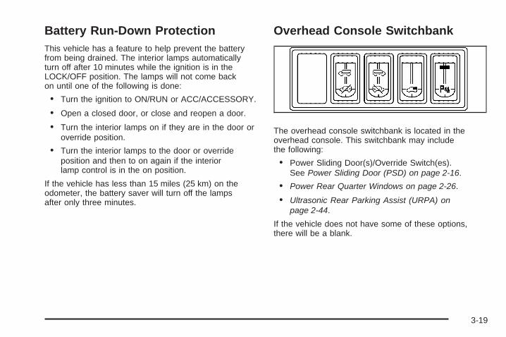
Battery Run-Down ProtectionThis vehicle has a feature to help prevent the batteryfrom being drained. The interior lamps automaticallyturn off after 10 minutes while the ignition is in theLOCK/OFF position. The lamps will not come backon until one of the following is done:
• Turn the ignition to ON/RUN or ACC/ACCESSORY.
• Open a closed door, or close and reopen a door.
• Turn the interior lamps on if they are in the door oroverride position.
• Turn the interior lamps to the door or overrideposition and then to on again if the interiorlamp control is in the on position.
If the vehicle has less than 15 miles (25 km) on theodometer, the battery saver will turn off the lampsafter only three minutes.
Overhead Console Switchbank
The overhead console switchbank is located in theoverhead console. This switchbank may includethe following:
• Power Sliding Door(s)/Override Switch(es).See Power Sliding Door (PSD) on page 2-16.
• Power Rear Quarter Windows on page 2-26.
• Ultrasonic Rear Parking Assist (URPA) onpage 2-44.
If the vehicle does not have some of these options,there will be a blank.
3-19
Accessory Power Outlet(s)The accessory power outlets can be used to plug inelectrical equipment, such as a cellular phone.
The vehicle may have two accessory power outlets.There may be one outlet located below the climatecontrols on the instrument panel and one outletlocated in the rear compartment on the driver side.
Pull the cover down to use the accessory power outlet.When not in use, keep the cover on.
To remove the rear accessory power outlet cover, pullthe tab on the cover. To put the cover back on, line up thetabs at the back of the cover and put the cover in place.Push down the tab to secure the cover. When not in use,always cover the rear accessory power outlet with theprotective cap.
Notice: Leaving electrical equipment on forextended periods will drain the battery. Alwaysunplug electrical equipment when not in use and donot plug in equipment that exceeds the maximumamperage rating of 20 amperes.
Certain electrical accessories may not be compatiblewith the accessory power outlet and could result in blownvehicle or adapter fuses. If you experience a problemsee your dealer/retailer for additional information onaccessory power outlets.
Notice: Adding any electrical equipment to thevehicle can damage it or keep other componentsfrom working as they should. The repairs would notbe covered by the vehicle warranty. Do not useequipment exceeding maximum amperage rating of20 amperes. Check with your dealer/retailer beforeadding electrical equipment.
When adding electrical equipment, be sure to followthe proper installation instructions included withthe equipment.
Notice: Improper use of the power outlet can causedamage not covered by your warranty. Do not hangany type of accessory or accessory bracket from theplug because the power outlets are designed foraccessory power plugs only.
3-20
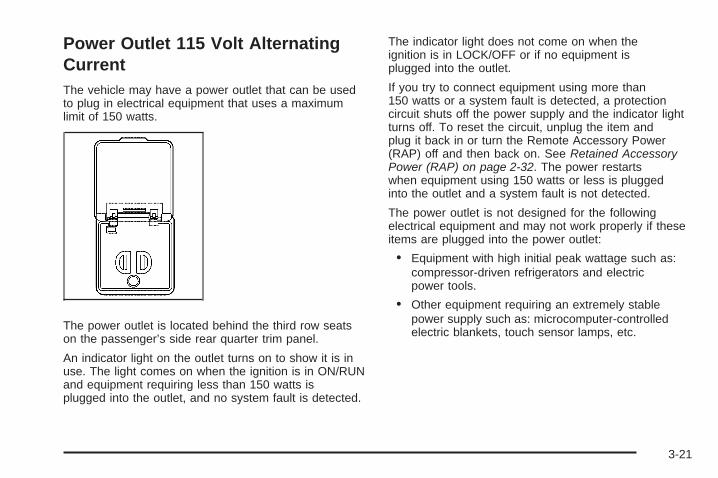
Power Outlet 115 Volt AlternatingCurrentThe vehicle may have a power outlet that can be usedto plug in electrical equipment that uses a maximumlimit of 150 watts.
The power outlet is located behind the third row seatson the passenger’s side rear quarter trim panel.
An indicator light on the outlet turns on to show it is inuse. The light comes on when the ignition is in ON/RUNand equipment requiring less than 150 watts isplugged into the outlet, and no system fault is detected.
The indicator light does not come on when theignition is in LOCK/OFF or if no equipment isplugged into the outlet.
If you try to connect equipment using more than150 watts or a system fault is detected, a protectioncircuit shuts off the power supply and the indicator lightturns off. To reset the circuit, unplug the item andplug it back in or turn the Remote Accessory Power(RAP) off and then back on. See Retained AccessoryPower (RAP) on page 2-32. The power restartswhen equipment using 150 watts or less is pluggedinto the outlet and a system fault is not detected.
The power outlet is not designed for the followingelectrical equipment and may not work properly if theseitems are plugged into the power outlet:
• Equipment with high initial peak wattage such as:compressor-driven refrigerators and electricpower tools.
• Other equipment requiring an extremely stablepower supply such as: microcomputer-controlledelectric blankets, touch sensor lamps, etc.
3-21
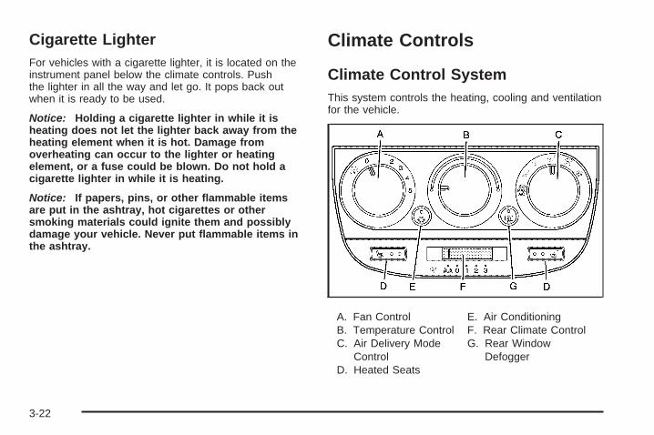
Cigarette LighterFor vehicles with a cigarette lighter, it is located on theinstrument panel below the climate controls. Pushthe lighter in all the way and let go. It pops back outwhen it is ready to be used.
Notice: Holding a cigarette lighter in while it isheating does not let the lighter back away from theheating element when it is hot. Damage fromoverheating can occur to the lighter or heatingelement, or a fuse could be blown. Do not hold acigarette lighter in while it is heating.
Notice: If papers, pins, or other flammable itemsare put in the ashtray, hot cigarettes or othersmoking materials could ignite them and possiblydamage your vehicle. Never put flammable items inthe ashtray.
Climate Controls
Climate Control SystemThis system controls the heating, cooling and ventilationfor the vehicle.
A. Fan ControlB. Temperature ControlC. Air Delivery Mode
ControlD. Heated Seats
E. Air ConditioningF. Rear Climate ControlG. Rear Window
Defogger
3-22
9 (Off): Turn the fan control all the waycounterclockwise to turn the front system off.
A (Fan Control): Turn clockwise or counterclockwiseto increase or decrease the fan speed.
Temperature Control: Turn clockwise orcounterclockwise to increase or decrease the airtemperature inside the vehicle.
Air Delivery Mode Control: Turn clockwise orcounterclockwise to change the current airflow mode.
To change the current mode, select one of the following:
@ MAX A/C (Maximum Air Conditioning): Turnthe air delivery mode knob to this position for maximumair conditioning. This selects the air conditioning andrecirculation modes for maximum cooling of the vehicle.Air is directed to the instrument panel outlets.
Recirculation: This mode recirculates and helps toquickly cool the air inside the vehicle. It can be used toprevent outside air and odors from entering the vehicle.This mode is automatically selected when MAX A/C isturned on.
H (Vent): Air is directed to the instrument paneloutlets.
) (Bi-Level): Air is divided between the instrumentpanel and floor outlets. Some air is directed towards thewindshield and side window outlets.
6 (Floor): Air is directed to the floor outlets. Use thismode to send air to the rear of the vehicle. Keep the areaunder the front seats free of objects that could obstructairflow to the rear of the vehicle.
- (Defog): This mode clears the windows of fog ormoisture. Air is directed to the windshield and the flooroutlets. When this mode is selected, the system runsthe air-conditioning compressor unless the outsidetemperature is at or below freezing. The recirculationmode cannot be selected while in the defog mode.
0 (Defrost): This mode clears the windshield of fogor frost more quickly. Air is directed to the windshieldand the side window outlets, with some air directed tothe floor outlets. In this mode, the system automaticallyruns the air-conditioning system, unless the outsidetemperature is at or below freezing. Recirculation cannotbe selected while in the defrost mode.
Do not drive the vehicle until all the windows are clear.
3-23
# (Air Conditioning): Press to turn the airconditioning system on or off. The fan must be on tooperate the air conditioning. An indicator light comeson when the air conditioning is on.
A slight change in engine performance may benoticeable when the air conditioning compressor shutsoff and turns on again. This is normal. The systemis designed to make adjustments to help with fueleconomy while still maintaining the selectedtemperature.
On hot days, open the windows to let hot inside airescape; then close them. This helps to reduce the timeit takes for the vehicle to cool down so the systemoperates more efficiently.
The air conditioning system removes moisture fromthe air, so a small amount of water might drip underthe vehicle while idling or after turning off the engine.This is normal.
Outside Air: Outside air is automatically selected inany mode, except maximum air conditioning.
Rear Window DefoggerThe rear window defogger uses a warming grid toremove fog from the rear window.
< Rear Window Defogger: Press to turn the rearwindow defogger on or off. An indicator light comes onwhen the rear window defogger is on.
The rear window defogger turns off about 15 minutesafter the button is pressed. If turned on again, thedefogger will only run for about five minutes beforeturning off. The defogger can also be turned offby turning off the engine.
Notice: Do not use anything sharp on the inside ofthe rear window. If you do, you could cut or damagethe warming grid, and the repairs would not becovered by the vehicle warranty. Do not attach atemporary vehicle license, tape, a decal or anythingsimilar to the defogger grid.
( (Heated Seats): Press to turn on the heated seats.See Heated Seats on page 1-3 for additional information.
3-24
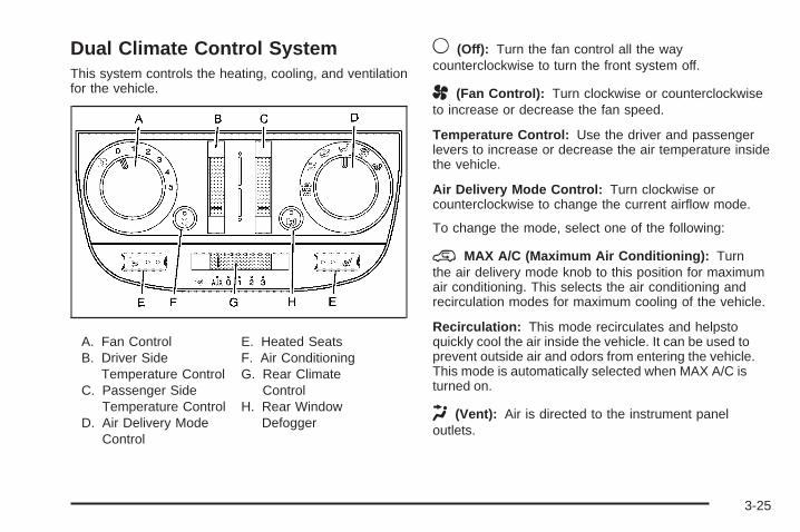
Dual Climate Control SystemThis system controls the heating, cooling, and ventilationfor the vehicle.
A. Fan ControlB. Driver Side
Temperature ControlC. Passenger Side
Temperature ControlD. Air Delivery Mode
Control
E. Heated SeatsF. Air ConditioningG. Rear Climate
ControlH. Rear Window
Defogger
9 (Off): Turn the fan control all the waycounterclockwise to turn the front system off.
A (Fan Control): Turn clockwise or counterclockwiseto increase or decrease the fan speed.
Temperature Control: Use the driver and passengerlevers to increase or decrease the air temperature insidethe vehicle.
Air Delivery Mode Control: Turn clockwise orcounterclockwise to change the current airflow mode.
To change the mode, select one of the following:
@ MAX A/C (Maximum Air Conditioning): Turnthe air delivery mode knob to this position for maximumair conditioning. This selects the air conditioning andrecirculation modes for maximum cooling of the vehicle.
Recirculation: This mode recirculates and helpstoquickly cool the air inside the vehicle. It can be used toprevent outside air and odors from entering the vehicle.This mode is automatically selected when MAX A/C isturned on.
H (Vent): Air is directed to the instrument paneloutlets.
3-25
) (Bi-Level): Air is divided between the instrumentpanel and floor outlets. Some air is directed towards thewindshield and side window outlets.
6 (Floor): Air is directed to the floor outlets. Use thismode to send air to the rear of the vehicle. Keep thearea under the front seats free of objects that couldobstruct airflow to the rear of the vehicle.
- (Defog): This mode clears the windows of fog ormoisture. Air is directed to the windshield and the flooroutlets. When this mode is selected, the system runsthe air-conditioning compressor unless the outsidetemperature is at or below freezing. The recirculationmode cannot be selected while in the defog mode.
0 (Defrost): This mode clears the windshield of fogor frost more quickly. Air is directed to the windshieldand the side window outlets, with some air directed tothe floor outlets. In this mode, the system automaticallyruns the air-conditioning system, unless the outsidetemperature is at or below freezing. Recirculation cannotbe selected while in the defrost mode.
Do not drive the vehicle until all the windows are clear.
# (Air Conditioning): Press to turn the airconditioning system on or off. The fan must be onto operate the air conditioning. An indicator lightcomes on when the air conditioning is on.
A slight change in engine performance may benoticeable when the air conditioning turns off and onagain. This is normal. The system is designed to makeadjustments to help with fuel economy while stillmaintaining the selected temperature.
On hot days, open the windows to let hot inside airescape; then close them. This helps to reduce the timeit takes for the vehicle to cool down so the systemoperates more efficiently.
The air conditioning system removes moisture fromthe air, so a small amount of water might drip underthe vehicle while idling or after turning off the engine.This is normal.
Outside Air: Outside air is automatically selected inany mode, except maximum air conditioning.
3-26
Rear Window DefoggerThe rear window defogger uses a warming grid toremove fog from the rear window.
< Rear Window Defogger: Press to turn the rearwindow defogger on or off. An indicator light comes onwhen the rear window defogger is on.
The rear window defogger turns off about 15 minutesafter the button is pressed. If turned on again, thedefogger will only run for about five minutes beforeturning off. The defogger can also be turned offby turning off the engine.
Notice: Do not use anything sharp on the inside ofthe rear window. If you do, you could cut or damagethe warming grid, and the repairs would not becovered by the vehicle warranty. Do not attach atemporary vehicle license, tape, a decal or anythingsimilar to the defogger grid.
( (Heated Seats): Press to turn on the heated seats.See Heated Seats on page 1-3 for additionalinformation.
Outlet AdjustmentUse the louvers located on the air outlets to change thedirection of the airflow.
Use the thumbwheels on the driver side and passengerside air outlets to open or close the airflow fromthese outlets.
Operation Tips• Clear away any ice, snow, or leaves from the air
inlets at the base of the vehicle that could blockthe flow of air into the vehicle.
• Do not use any non-GM approved hood deflectorsthat could adversely affect the performance of thesystem.
• Keep the path under the front seats clear of objectsto help circulate the air inside of the vehicle moreeffectively.
3-27
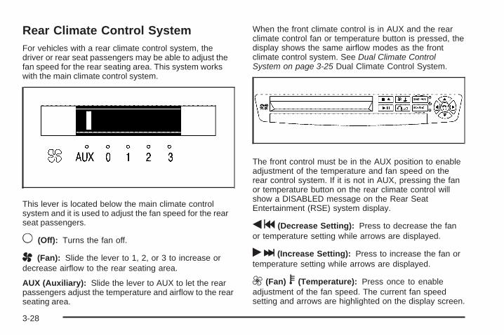
Rear Climate Control SystemFor vehicles with a rear climate control system, thedriver or rear seat passengers may be able to adjust thefan speed for the rear seating area. This system workswith the main climate control system.
This lever is located below the main climate controlsystem and it is used to adjust the fan speed for the rearseat passengers.
9 (Off): Turns the fan off.
A (Fan): Slide the lever to 1, 2, or 3 to increase ordecrease airflow to the rear seating area.
AUX (Auxiliary): Slide the lever to AUX to let the rearpassengers adjust the temperature and airflow to the rearseating area.
When the front climate control is in AUX and the rearclimate control fan or temperature button is pressed, thedisplay shows the same airflow modes as the frontclimate control system. See Dual Climate ControlSystem on page 3-25 Dual Climate Control System.
The front control must be in the AUX position to enableadjustment of the temperature and fan speed on therear control system. If it is not in AUX, pressing the fanor temperature button on the rear climate control willshow a DISABLED message on the Rear SeatEntertainment (RSE) system display.
qg (Decrease Setting): Press to decrease the fanor temperature setting while arrows are displayed.
rl (Increase Setting): Press to increase the fan ortemperature setting while arrows are displayed.
9 (Fan) b (Temperature): Press once to enableadjustment of the fan speed. The current fan speedsetting and arrows are highlighted on the display screen.
3-28

Press either qg or rl to increase or decreasefan speed. The on screen display disappears aftera few seconds.
Press 9 b twice to enable temperature adjustment.After pressing 9 b , the current temperature settingsare highlighted and appear in the on screen display. Thearrows indicate that to increase or decreasetemperature, press either the qg or rl button.The on screen display disappears after a few seconds.
Press 9 b a third time to turn off the on screendisplay.
QR : Press to toggle between the fan andtemperature settings.
Rear Air OutletsThe outlet behind the driver side rear seat is for the coldair return. Be sure to keep it free from obstructions.Also, keep the area around the base of the centerinstrument panel console, between and under the frontseats, free of objects that could also obstruct airflowto the rear seating area.
See Climate Control System on page 3-22 or DualClimate Control System on page 3-25 for moreinformation on the main climate control system.See Outlet Adjustment on page 3-27 for information onventilation.
Passenger Compartment Air FilterBoth outside and recirculated air are routed through apassenger compartment filter. Pollen, dust particles andother contaminants are removed by the filter. Airreductions indicate that the filter needs to be replaced.See Scheduled Maintenance on page 6-4 forreplacement intervals.
The access panel for the passenger compartment airfilter is located in the back of the glove box. To replacethe filter:
1. Pull the tab located on the outer access panelup and out.
3-29
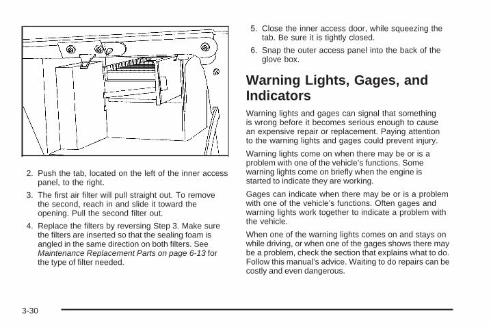
2. Push the tab, located on the left of the inner accesspanel, to the right.
3. The first air filter will pull straight out. To removethe second, reach in and slide it toward theopening. Pull the second filter out.
4. Replace the filters by reversing Step 3. Make surethe filters are inserted so that the sealing foam isangled in the same direction on both filters. SeeMaintenance Replacement Parts on page 6-13 forthe type of filter needed.
5. Close the inner access door, while squeezing thetab. Be sure it is tightly closed.
6. Snap the outer access panel into the back of theglove box.
Warning Lights, Gages, andIndicatorsWarning lights and gages can signal that somethingis wrong before it becomes serious enough to causean expensive repair or replacement. Paying attentionto the warning lights and gages could prevent injury.
Warning lights come on when there may be or is aproblem with one of the vehicle’s functions. Somewarning lights come on briefly when the engine isstarted to indicate they are working.
Gages can indicate when there may be or is a problemwith one of the vehicle’s functions. Often gages andwarning lights work together to indicate a problem withthe vehicle.
When one of the warning lights comes on and stays onwhile driving, or when one of the gages shows there maybe a problem, check the section that explains what to do.Follow this manual’s advice. Waiting to do repairs can becostly and even dangerous.
3-30

Instrument Panel ClusterYour instrument panel cluster is designed to let you know at a glance how your vehicle is running. You will knowhow fast you are going, how much fuel you are using, and many other things you will need to drive safely andeconomically. The indicator warning lights and gages are explained on the following pages.
3-31
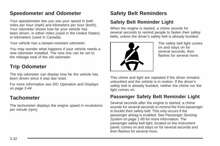
Speedometer and OdometerYour speedometer lets you see your speed in bothmiles per hour (mph) and kilometers per hour (km/h).Your odometer shows how far your vehicle hasbeen driven, in either miles (used in the United States)or kilometers (used in Canada).
Your vehicle has a tamper-resistant odometer.
You may wonder what happens if your vehicle needs anew odometer installed. The new one can be set tothe mileage total of the old odometer.
Trip OdometerThe trip odometer can display how far the vehicle hasbeen driven since it was last reset.
For more information see DIC Operation and Displayson page 3-44.
TachometerThe tachometer displays the engine speed in revolutionsper minute (rpm).
Safety Belt Reminders
Safety Belt Reminder LightWhen the engine is started, a chime sounds forseveral seconds to remind people to fasten their safetybelts, unless the driver’s safety belt is already buckled.
The safety belt light comeson and stays on forseveral seconds, thenflashes for several more.
This chime and light are repeated if the driver remainsunbuckled and the vehicle is in motion. If the driver’ssafety belt is already buckled, neither the chime nor thelight comes on.
Passenger Safety Belt Reminder LightSeveral seconds after the engine is started, a chimesounds for several seconds to remind the front passengerto buckle their safety belt. This only occurs if thepassenger airbag is enabled. See Passenger SensingSystem on page 1-85 for more information. Thepassenger safety belt light, located on the instrumentpanel, comes on and stays on for several seconds andthen flashes for several more.
3-32
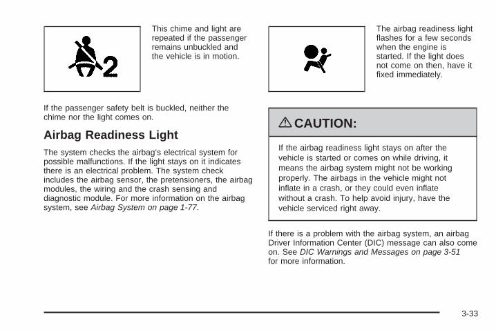
This chime and light arerepeated if the passengerremains unbuckled andthe vehicle is in motion.
If the passenger safety belt is buckled, neither thechime nor the light comes on.
Airbag Readiness LightThe system checks the airbag’s electrical system forpossible malfunctions. If the light stays on it indicatesthere is an electrical problem. The system checkincludes the airbag sensor, the pretensioners, the airbagmodules, the wiring and the crash sensing anddiagnostic module. For more information on the airbagsystem, see Airbag System on page 1-77.
The airbag readiness lightflashes for a few secondswhen the engine isstarted. If the light doesnot come on then, have itfixed immediately.
{CAUTION:
If the airbag readiness light stays on after thevehicle is started or comes on while driving, itmeans the airbag system might not be workingproperly. The airbags in the vehicle might notinflate in a crash, or they could even inflatewithout a crash. To help avoid injury, have thevehicle serviced right away.
If there is a problem with the airbag system, an airbagDriver Information Center (DIC) message can also comeon. See DIC Warnings and Messages on page 3-51for more information.
3-33
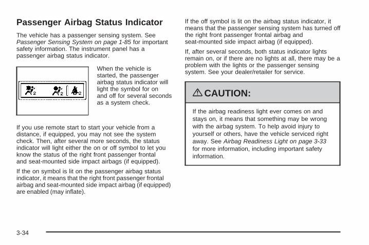
Passenger Airbag Status IndicatorThe vehicle has a passenger sensing system. SeePassenger Sensing System on page 1-85 for importantsafety information. The instrument panel has apassenger airbag status indicator.
When the vehicle isstarted, the passengerairbag status indicator willlight the symbol for onand off for several secondsas a system check.
If you use remote start to start your vehicle from adistance, if equipped, you may not see the systemcheck. Then, after several more seconds, the statusindicator will light either the on or off symbol to let youknow the status of the right front passenger frontaland seat-mounted side impact airbags (if equipped).
If the on symbol is lit on the passenger airbag statusindicator, it means that the right front passenger frontalairbag and seat-mounted side impact airbag (if equipped)are enabled (may inflate).
If the off symbol is lit on the airbag status indicator, itmeans that the passenger sensing system has turned offthe right front passenger frontal airbag andseat-mounted side impact airbag (if equipped).
If, after several seconds, both status indicator lightsremain on, or if there are no lights at all, there may be aproblem with the lights or the passenger sensingsystem. See your dealer/retailer for service.
{CAUTION:
If the airbag readiness light ever comes on andstays on, it means that something may be wrongwith the airbag system. To help avoid injury toyourself or others, have the vehicle serviced rightaway. See Airbag Readiness Light on page 3-33for more information, including important safetyinformation.
3-34
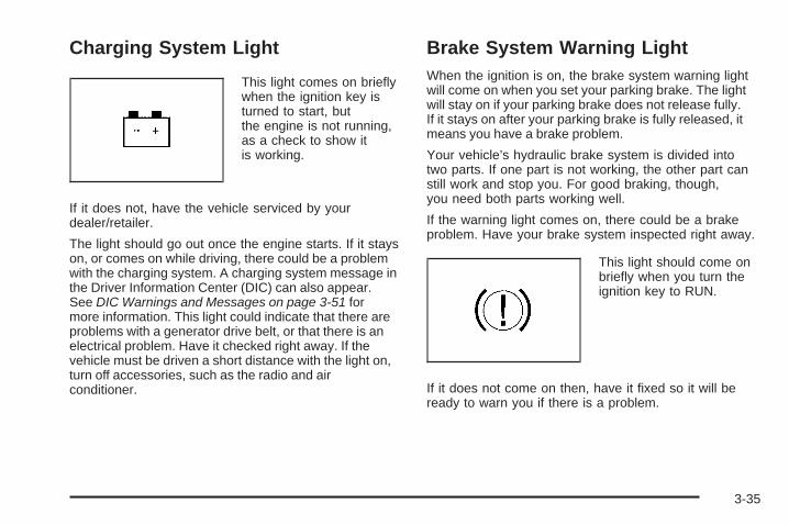
Charging System Light
This light comes on brieflywhen the ignition key isturned to start, butthe engine is not running,as a check to show itis working.
If it does not, have the vehicle serviced by yourdealer/retailer.
The light should go out once the engine starts. If it stayson, or comes on while driving, there could be a problemwith the charging system. A charging system message inthe Driver Information Center (DIC) can also appear.See DIC Warnings and Messages on page 3-51 formore information. This light could indicate that there areproblems with a generator drive belt, or that there is anelectrical problem. Have it checked right away. If thevehicle must be driven a short distance with the light on,turn off accessories, such as the radio and airconditioner.
Brake System Warning LightWhen the ignition is on, the brake system warning lightwill come on when you set your parking brake. The lightwill stay on if your parking brake does not release fully.If it stays on after your parking brake is fully released, itmeans you have a brake problem.
Your vehicle’s hydraulic brake system is divided intotwo parts. If one part is not working, the other part canstill work and stop you. For good braking, though,you need both parts working well.
If the warning light comes on, there could be a brakeproblem. Have your brake system inspected right away.
This light should come onbriefly when you turn theignition key to RUN.
If it does not come on then, have it fixed so it will beready to warn you if there is a problem.
3-35
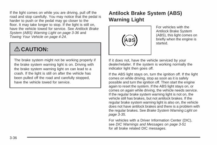
If the light comes on while you are driving, pull off theroad and stop carefully. You may notice that the pedal isharder to push or the pedal may go closer to thefloor. It may take longer to stop. If the light is still on,have the vehicle towed for service. See Antilock BrakeSystem (ABS) Warning Light on page 3-36 andTowing Your Vehicle on page 4-24.
{CAUTION:
The brake system might not be working properly ifthe brake system warning light is on. Driving withthe brake system warning light on can lead to acrash. If the light is still on after the vehicle hasbeen pulled off the road and carefully stopped,have the vehicle towed for service.
Antilock Brake System (ABS)Warning Light
For vehicles with theAntilock Brake System(ABS), this light comes onbriefly when the engine isstarted.
If it does not, have the vehicle serviced by yourdealer/retailer. If the system is working normally theindicator light then goes off.
If the ABS light stays on, turn the ignition off. If the lightcomes on while driving, stop as soon as it is safelypossible and turn the ignition off. Then start the engineagain to reset the system. If the ABS light stays on, orcomes on again while driving, the vehicle needs service.If the regular brake system warning light is not on, thevehicle still has brakes, but not antilock brakes. If theregular brake system warning light is also on, the vehicledoes not have antilock brakes and there is a problem withthe regular brakes. See Brake System Warning Light onpage 3-35.
For vehicles with a Driver Information Center (DIC),see DIC Warnings and Messages on page 3-51for all brake related DIC messages.
3-36
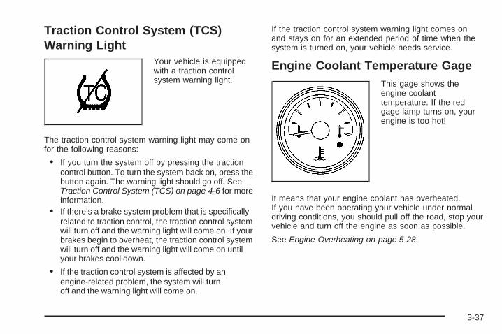
Traction Control System (TCS)Warning Light
Your vehicle is equippedwith a traction controlsystem warning light.
The traction control system warning light may come onfor the following reasons:
• If you turn the system off by pressing the tractioncontrol button. To turn the system back on, press thebutton again. The warning light should go off. SeeTraction Control System (TCS) on page 4-6 for moreinformation.
• If there’s a brake system problem that is specificallyrelated to traction control, the traction control systemwill turn off and the warning light will come on. If yourbrakes begin to overheat, the traction control systemwill turn off and the warning light will come on untilyour brakes cool down.
• If the traction control system is affected by anengine-related problem, the system will turnoff and the warning light will come on.
If the traction control system warning light comes onand stays on for an extended period of time when thesystem is turned on, your vehicle needs service.
Engine Coolant Temperature GageThis gage shows theengine coolanttemperature. If the redgage lamp turns on, yourengine is too hot!
It means that your engine coolant has overheated.If you have been operating your vehicle under normaldriving conditions, you should pull off the road, stop yourvehicle and turn off the engine as soon as possible.
See Engine Overheating on page 5-28.
3-37
Tire Pressure Light
For vehicles with a tirepressure light, this lightcomes on briefly when theengine is started andprovides information abouttire pressures and the TirePressure MonitoringSystem.
When the Light is On SteadyThis indicates that one or more of the tires aresignificantly underinflated.
A tire pressure message in the Driver InformationCenter (DIC), can accompany the light. See DICWarnings and Messages on page 3-51 for moreinformation. Stop and check the tires as soon as it issafe to do so. If a tire is underinflated, inflate to theproper pressure. See Tires on page 5-47 for moreinformation.
When the Light Flashes First and Then isOn SteadyThis indicates that there could be a problem with theTire Pressure Monitor System. The light flashes for abouta minute and stays on steady for the remainder of theignition cycle. This sequence repeats with every ignitioncycle. See Tire Pressure Monitor System on page 5-57for more information.
Malfunction Indicator Lamp
Check Engine LightA computer system called OBD II (On-BoardDiagnostics-Second Generation) monitors operation ofthe fuel, ignition, and emission control systems. Itensures that emissions are at acceptable levels for thelife of the vehicle, helping to produce a cleanerenvironment.
This light should come onwhen the ignition is on, butthe engine is not running,as a check to show itworking. If it does not, havethe vehicle serviced by yourdealer/retailer.
3-38
If the check engine light comes on and stays on, whilethe engine is running, this indicates that there is anOBD II problem and service is required.
Malfunctions often are indicated by the system beforeany problem is apparent. Being aware of the lightcan prevent more serious damage to the vehicle. Thissystem assists the service technician in correctlydiagnosing any malfunction.
Notice: If the vehicle is continually driven with thislight on, after a while, the emission controlsmight not work as well, the vehicle’s fuel economymight not be as good, and the engine might notrun as smoothly. This could lead to costly repairsthat might not be covered by the vehicle warranty.
Notice: Modifications made to the engine,transmission, exhaust, intake, or fuel system of thevehicle or the replacement of the original tireswith other than those of the same Tire PerformanceCriteria (TPC) can affect the vehicle’s emissioncontrols and can cause this light to come on.Modifications to these systems could lead to costlyrepairs not covered by the vehicle warranty. Thiscould also result in a failure to pass a requiredEmission Inspection/Maintenance test. SeeAccessories and Modifications on page 5-3.
This light comes on during a malfunction in one oftwo ways:
Light Flashing: A misfire condition has been detected.A misfire increases vehicle emissions and coulddamage the emission control system on the vehicle.Diagnosis and service might be required.
To prevent more serious damage to the vehicle:
• Reduce vehicle speed.
• Avoid hard accelerations.
• Avoid steep uphill grades.
• If towing a trailer, reduce the amount of cargo beinghauled as soon as it is possible.
If the light continues to flash, when it is safe to do so,stop the vehicle. Find a safe place to park the vehicle.Turn the key off, wait at least 10 seconds, and restartthe engine. If the light is still flashing, follow the previoussteps and see your dealer/retailer for service as soonas possible.
Light On Steady: An emission control systemmalfunction has been detected on the vehicle.Diagnosis and service might be required.
3-39

An emission system malfunction might be corrected bydoing the following:
• Make sure the fuel cap is fully installed. See Fillingthe Tank on page 5-10. The diagnostic system candetermine if the fuel cap has been left off orimproperly installed. A loose or missing fuel capallows fuel to evaporate into the atmosphere. A fewdriving trips with the cap properly installed shouldturn the light off.
• If the vehicle has been driven through a deep puddleof water, the vehicle’s electrical system might be wet.The condition is usually corrected when the electricalsystem dries out. A few driving trips should turn thelight off.
• Make sure to fuel the vehicle with quality fuel. Poorfuel quality causes the engine not to run as efficientlyas designed and can cause: stalling after start-up,stalling when the vehicle is changed into gear,misfiring, hesitation on acceleration, or stumbling onacceleration. These conditions might go away oncethe engine is warmed up.
If one or more of these conditions occurs, change thefuel brand used. It will require at least one full tank ofthe proper fuel to turn the light off.See Gasoline Octane on page 5-6.
If none of the above have made the light turn off, yourdealer/retailer can check the vehicle. The dealer/retailerhas the proper test equipment and diagnostic tools to fixany mechanical or electrical problems that might havedeveloped.
Emissions Inspection and MaintenanceProgramsSome state/provincial and local governments have ormight begin programs to inspect the emission controlequipment on the vehicle. Failure to pass this inspectioncould prevent getting a vehicle registration.
Here are some things to know to help the vehicle passan inspection:
• The vehicle will not pass this inspection if the checkengine light is on with the engine running, or if thekey is in the ON/RUN and the light is not on.
• The vehicle will not pass this inspection if theOBD II (on-board diagnostic) system determinesthat critical emission control systems have notbeen completely diagnosed by the system. Thevehicle would be considered not ready for inspection.This can happen if the battery has recently beenreplaced or if the battery has run down. Thediagnostic system is designed to evaluate criticalemission control systems during normal driving.
3-40
This can take several days of routine driving. If thishas been done and the vehicle still does not pass theinspection for lack of OBD II system readiness, yourdealer/retailer can prepare the vehicle for inspection.
Oil Pressure Light
{CAUTION:
Do not keep driving if the oil pressure is low. Theengine can become so hot that it catches fire.Someone could be burned. Check the oil as soonas possible and have the vehicle serviced.
Notice: Lack of proper engine oil maintenancecan damage the engine. The repairs would not becovered by the vehicle warranty. Always followthe maintenance schedule in this manual forchanging engine oil.
This light comes on briefly while starting the engine.If it does not, have the vehicle serviced by yourdealer/retailer. If the system is working normally theindicator light then goes off.
If the light comes on and stays on, it means that oil isnot flowing through the engine properly. The vehiclecould be low on oil and it might have some other systemproblem.
Security Light
For information regardingthis light and the vehicle’ssecurity system, seeContent Theft-Deterrent onpage 2-27.
3-41
Cruise Control LightThis light comes onwhenever the cruisecontrol is set.
The light goes out when the cruise control is turned off.See Cruise Control on page 3-10 for more information.
Highbeam On LightThis light comes on whenthe high-beam headlampsare in use.
See Headlamp High/Low-Beam Changer on page 3-8for more information.
Fuel GageWhen the indicator nearsempty, you still have a littlefuel left, but you should getmore soon.
Your fuel gage tells you about how much fuel you haveleft when the ignition is on.Here are four things some owners ask about. All thesethings are normal and do not indicate that anything iswrong with the fuel gage.
• At the gas station, the gas pump shuts off before thegage reads full.
• It takes a little more (or less) fuel to fill up than thegage reads. For example, the gage read half full, butit took more (or less) than half of the tank’s capacityto fill it.
• The gage pointer may move while cornering, brakingor speeding up.
• The gage may not indicate empty when the ignition isturned off.
3-42

Low Fuel Warning LightThe light next to the fuel gage will come on briefly whenyou are starting the engine.
This light comes on when the fuel tank is low on fuel.To turn it off, add fuel to the fuel tank.
Driver Information Center (DIC)Your vehicle has a Driver Information Center (DIC).
All messages appear in the DIC display located in theinstrument panel cluster, below the tachometer. The DICbuttons are located on the center of the instrumentpanel, below the center outlets.
The DIC comes on when the ignition is on. After a shortdelay, the DIC displays WELCOME DRIVER (1 or 2) if apersonalized key 1 or 2 is used, and then the informationthat was last displayed before the engine was turned off.The driver number also corresponds to the numbers,1 or 2, on the back of the remote keyless entrytransmitters.
The DIC displays the odometer, trip odometers, fueleconomy, trip computer, vehicle system information, andcompass display, if equipped. It also displays warningmessages if a system problem is detected. In addition,the DIC displays phone numbers that are called using theOnStar® system, if equipped. See OnStar® System onpage 2-47.
On some vehicles, the outside air temperatureautomatically appears in the bottom right corner of theDIC display when viewing all of the information screens,except for the oil life screens. If the outside airtemperature is at or below 37°F (3°C), the temperaturereading will toggle between displaying the outsidetemperature and the word ICE for two minutes. If there isa problem with the system that controls the temperaturedisplay, the letters OC (open circuit) or SC (short circuit)will appear on the display. If this occurs, have the vehicleserviced by your dealer/retailer.
The DIC also allows some features to be customizedor personalized, if equipped. See DIC VehiclePersonalization (Uplevel Only) on page 3-68 formore information.
3-43
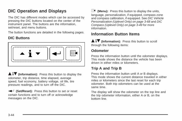
DIC Operation and DisplaysThe DIC has different modes which can be accessed bypressing the DIC buttons located on the center of theinstrument panel. The buttons are the information,set/reset, and menu buttons.
The button functions are detailed in the following pages.
DIC Buttons
Q 4R (Information): Press this button to display theodometer, trip distance, time elapsed, averagespeed, fuel economy, battery voltage, oil life, tirepressure readings, and to turn off the DIC.
r (Set/Reset): Press this button to set or resetcertain functions and to turn off or acknowledgemessages on the DIC.
q (Menu): Press this button to display the units,language, personalization, if equipped, compass zoneand compass calibration, if equipped. See DIC VehiclePersonalization (Uplevel Only) on page 3-68 and DICCompass (Uplevel Only) on page 3-49 for moreinformation.
Information Button Items
Q 4R (Information): Press this button to scrollthrough the following items:
OdometerPress the information button until the odometer displays.This mode shows the distance the vehicle has beendriven in either miles or kilometers.
Trip A and Trip BPress the information button until A or B displays.This mode shows the current distance traveled in eithermiles or kilometers since the last reset for each tripodometer. Both trip odometers can be used at thesame time.
The display will show the odometer on the top line andthe trip odometer information, either A or B, on thebottom line.
3-44
Each trip odometer can be reset to zero separately bypressing the set/reset button while the desired tripodometer is displayed.
There is also a retroactive trip odometer function thatperforms the following for each trip odometer:
• If the vehicle’s speed has exceeded 3 mph (5 km/h)during the current ignition cycle, this function willset the trip odometer to the distance drivenduring the current ignition cycle.
• If the vehicle’s speed has not exceeded 3 mph(5 km/h), this function will set the trip odometerto the distance driven during the previous ignitioncycle plus the distance driven during the currentignition cycle.
Press and hold the set/reset button for three seconds,then release the button. The retroactive trip odometervalue will be set into the currently displayed tripodometer.
Time ElapsedPress the information button until TIME ELAPSED :00displays. This mode is like a stopwatch, in that you canclock the time it takes to get from one point to another.Each of the fields for the hours, minutes, and secondsare two numeric digits.
Once TIME ELAPSED :00 is displayed, press theset/reset button to start the timing feature. Press theset/reset button again to stop it. If you will be startingand stopping your vehicle, during a trip for instance, theTIME ELAPSED feature will automatically start timingwhere it left off when you last stopped. To reset it, pressand hold the set/reset button for about 1.5 seconds.The display will return to zero.
Average SpeedPress the information button until AVERAGE SPEEDdisplays. This mode shows the average speed of thevehicle in miles per hour (mph) or kilometers per hour(km/h). This average is calculated based on the variousvehicle speed recorded since the last reset of this value.To reset the value, press the information button to displayAVERAGE SPEED, then press and hold the set/resetbutton. The display will return to zero.
3-45

Fuel RangePress the information button until FUEL RANGEdisplays. This mode shows the approximate number ofremaining miles or kilometers the vehicle can bedriven without refueling.
Fuel range is based on several factors, includingdistance travelled, fuel used, fuel capacity, etc. Thisestimate will change if driving conditions change.For example, if driving in traffic and making frequentstops, this mode may read one number, but if the vehicleis driven on a freeway, the number may change eventhough the same amount of fuel is in the fuel tank. Thisis because different driving conditions producedifferent fuel economies. Generally, freeway drivingproduces better fuel economy than city driving.Fuel range cannot be reset.
If your vehicle is low on fuel, FUEL RANGE LOW willdisplay followed by the LOW FUEL message. See “LOWFUEL” under DIC Warnings and Messages onpage 3-51 for more information.
Average Fuel EconomyPress the information button until AVG ECONOMYdisplays. This mode shows the approximate averagemiles per gallon (mpg) or liters per 100 kilometers(L/100 km). This number is calculated based on thenumber of mpg (L/100 km) recorded since the last timethis menu item was reset. To reset AVG ECONOMY,press and hold the set/reset button. The display willreturn to zero.
BatteryPress the information button until BATTERY displays.This mode shows the current battery voltage.
Your vehicle’s charging system regulates voltage basedon the state of the battery. The battery voltage mayfluctuate when viewing this information on the DIC.This is normal.
If there is a problem with the battery charging system, aDIC message will display. See DIC Warnings andMessages on page 3-51 and Electric PowerManagement on page 3-18 for more information.
3-46
Oil LifePress the information button until OIL LIFE displays.This mode shows an estimate of the oil’s remaininguseful life. If you see OIL LIFE 99% on the display, thatmeans 99% of the current oil life remains. The engineoil life system will alert you to change the oil on aschedule consistent with your driving conditions.
When the remaining oil life is low, the CHANGE OILSOON message will appear on the display. You shouldchange the oil as soon as possible. See Engine Oilon page 5-15. In addition to the engine oil life systemmonitoring the oil life, additional maintenance isrecommended in the Maintenance Schedule in thismanual. See Scheduled Maintenance on page 6-4 formore information.
Remember, you must reset the OIL LIFE yourself aftereach oil change. It will not reset itself. Also, be careful notto reset the OIL LIFE accidentally at any time other thanwhen the oil has just been changed. It cannot be resetaccurately until the next oil change. To reset the engineoil life system, see Engine Oil Life System on page 5-18.The display will show 100% when the system is reset.
Tire PressurePress the information button until FRONT TIREPRESSURE displays. This mode shows the pressurefor the front tires. To view the pressure for the rear tires,press the information button again until REAR TIREPRESSURE displays. The tire pressure will be shown ineither pounds per square inch (psi) or kilopascals (kPa).
If a low tire pressure condition is detected by the systemwhile driving, a message advising you to check thepressure in a specific tire will appear in the display. Thetire pressure light will also flash and then remain onduring the same ignition cycle. See Inflation - TirePressure on page 5-54 and DIC Warnings and Messageson page 3-51 for more information.
If the tire pressure display shows dashes or blanksinstead of a value, there may be a problem with yourvehicle. If this consistently occurs, see your dealerfor service.
3-47
Menu Button Items
q (Menu): Press this button to scroll through thefollowing items:
UnitsPress the menu button until UNITS displays. This modeallows you to select between English or Metric unitsof measurement. Once in this mode, press the set/resetbutton to select between ENGLISH or METRIC.
LanguagePress the menu button until the language screendisplays. This mode allows you to select the languagein which the DIC messages will appear. Once inthis mode, press the set/reset button to select amongthe following choices:
• English
• Francais (French)
• Espanol (Spanish)
Personalization (Uplevel Only)Press the menu button until PERSONAL PROGRAMdisplays. Your vehicle may have personalizationcapabilities that allow you to program certain features toa preferred setting for up to two drivers.
Your vehicle may also have customization capabilitiesthat allow you to program certain features to onepreferred setting. Customization features can only beprogrammed to one setting on the vehicle and cannot beprogrammed to a preferred setting for up to two drivers.See DIC Vehicle Personalization (Uplevel Only) onpage 3-68 for additional information on personalprogramming.
Compass Zone (Uplevel Only)To change the compass zone through the DIC, see DICCompass (Uplevel Only) on page 3-49.
Compass Calibration (Uplevel Only)The compass can be manually calibrated. To calibratethe compass through the DIC, see DIC Compass(Uplevel Only) on page 3-49.
3-48

DIC Compass (Uplevel Only)Your vehicle may have a compass in the DriverInformation Center (DIC).
Compass ZoneThe zone is set to zone eight upon leaving the factory.Your dealer/retailer will set the correct zone for yourlocation.
Under certain circumstances, such as during a longdistance cross-country trip or moving to a new state orprovince, it will be necessary to compensate for compassvariance by resetting the zone through the DIC if the zoneis not set correctly.
Compass variance is the difference between the earth’smagnetic north and true geographic north. If the compassis not set to the zone where you live, the compass maygive false readings. The compass must be set to thevariance zone in which the vehicle is traveling.
To adjust for compass variance, use the followingprocedure:
Compass Variance (Zone) Procedure1. Do not set the compass zone when the vehicle is
moving. Only set it when the vehicle is in P (Park).Press the menu button until COMPASS ZONEdisplays.
2. Find the vehicle’s current location and variancezone number on the map.Zones 1 through 15 are available.
3. Press the set/reset button to scroll through andselect the appropriate variance zone.The direction the vehicle is moving will be shown inthe top right corner of the DIC display.
4. If calibration is necessary, calibrate the compass.See “Compass Calibration Procedure” following.
3-49

Compass CalibrationThe compass can be manually calibrated. Only calibratethe compass in a magnetically clean and safe location,such as an open parking lot, where driving the vehicle incircles is not a danger. It is suggested to calibrate awayfrom tall buildings, utility wires, manhole covers, or otherindustrial structures, if possible.
If CAL should ever appear in the DIC display, thecompass should be calibrated.
If the DIC display does not show a heading, forexample, N for North, or the heading does not changeafter making turns, there may be a strong magnetic fieldinterfering with the compass. Such interference may becaused by a magnetic CB or cell phone antenna mount, amagnetic emergency light, magnetic note pad holder, orany other magnetic item. Turn off the vehicle, move themagnetic item, then turn on the vehicle and calibrate thecompass.
To calibrate the compass, use the following procedure:
Compass Calibration Procedure1. Before calibrating the compass, make sure the
compass zone is set to the variance zone inwhich the vehicle is located. See “CompassVariance (Zone) Procedure” earlier in this section.Do not operate any switches such as window,sunroof, climate controls, seats, etc. duringthe calibration procedure.
2. Press the menu button until COMPASSCALIBRATION displays.
3. Press the set/reset button to start the compasscalibration.
4. The DIC will display CALIBRATION BEGUN DRIVEUNTIL DONE. Drive the vehicle in tight circles atless than 5 mph (8 km/h) to complete the calibration.The DIC will display CALIBRATION FINISHEDfor a few seconds when the calibration is complete.
3-50
DIC Warnings and MessagesMessages are displayed on the DIC to notify the driverthat the status of the vehicle has changed and that someaction may be needed by the driver to correct thecondition. Multiple messages may appear one afteranother.
Some messages may not require immediate action, butyou can press any of the DIC buttons to acknowledgethat you received the message and clear it from the DICdisplay.
Some messages cannot be cleared from the DIC displaybecause they are more urgent. These messages requireaction before they can be cleared.
If there are any active warning messages when thevehicle is turned off, two chimes sound and the DIC goesinto a reminder mode. The reminder mode displays anyactive message. If there are multiple messages, the DICdisplays each message for five seconds. After eachactive message is displayed once, the reminder modeturns off.
You should take any messages that appear on thedisplay seriously and remember that clearing themessages will only make the messages disappear,not correct the problem.
The following are the possible messages that can bedisplayed and some information about them.
A/C OFF FOR ENGINE PROTECTIONThis message displays when the engine coolantbecomes hotter than the normal operating temperature.See Engine Coolant Temperature Gage on page 3-37. Toavoid added strain on a hot engine, the air conditioningcompressor is automatically turned off. When the coolanttemperature returns to normal, the air conditioningcompressor turns back on. You can continue to drive yourvehicle.
This message comes on while the ignition is in ON/RUN.Press any of the DIC buttons to acknowledge thiswarning message and to clear it from the screen.
This message continues to display for two seconds if ithas not been acknowledged when the engine isturned off. It also re-displays for two seconds if themessage has been acknowledged, but the condition stillexists when the engine is turned off.
If the condition still exists, the message re-appearswhen the engine is turned on. If this message continuesto appear, have the system repaired by yourdealer/retailer as soon as possible to avoid damage tothe engine.
3-51
BATTERY SAVER ACTIVEThis message displays when the system detects that thebattery voltage is dropping beyond a reasonable level.The battery saver system starts reducing certain featuresof the vehicle that you may be able to notice. At the pointthat the features are disabled, this message is displayed.It means that the vehicle is trying to save the charge inthe battery.
Turn off all unnecessary accessories to allow the batteryto recharge.
The normal battery voltage range is 11.5 to 15.5 volts.You can monitor the battery voltage by pressing theinformation button until BATTERY displays.
CHANGE OIL SOONThis message displays when service is required for thevehicle. See your dealer/retailer. See Engine Oil onpage 5-15 and Scheduled Maintenance on page 6-4 formore information.
The CHANGE OIL SOON message is reset byacknowledging the message. The OIL LIFE screenunder the gages menu on the DIC must also be reset.See “Oil Life” under DIC Operation and Displays onpage 3-44 and Engine Oil Life System on page 5-18.
This message displays while the ignition is in ON/RUN.Press any of the DIC buttons to acknowledge thismessage and to clear it from the screen.
This message continues to display for two seconds if ithas not been acknowledged when the engine isturned off. It also re-displays for two seconds if themessage has been acknowledged, but the condition stillexists when the engine is turned off.
If the condition still exists, the message re-appearswhen the engine is turned on.
CHARGING SYSTEM FAILUREThis message displays when there is a problem with thegenerator and battery charging systems. Driving withthis problem could drain the battery. Turn off allunnecessary accessories. Stop and turn off the vehicleas soon as it is safe to do so. Have the electricalsystem checked by your dealer/retailer immediately.
This message displays and a chime sounds while theignition is in ON/RUN. Press any of the DIC buttonsto acknowledge this message and to clear it fromthe screen.
This message continues to display for two seconds if ithas not been acknowledged when the engine isturned off. It also re-displays for two seconds if themessage has been acknowledged, but the condition stillexists when the engine is turned off.
If the condition still exists, the message re-appearswhen the engine is turned on.
3-52
CHECK GAS CAPThis message displays if the fuel cap is not on, or is notfully tightened. Check the fuel cap to ensure that it ison properly. See Filling the Tank on page 5-10 for moreinformation.
This message displays and a chime sounds while theignition is in ON/RUN. Press any of the DIC buttonsto acknowledge this message and to clear it from thescreen.
This message continues to display for two seconds if ithas not been acknowledged when the engine is turnedoff. It also re-displays for two seconds if the message hasbeen acknowledged, but the condition still exists whenthe engine is turned off.
If the condition still exists, the message re-appearswhen the engine is turned on.
CHECK TIRE PRESSUREThis message displays when the pressure in one ormore of the vehicle’s tires needs to be checked. Thismessage also displays LEFT FRONT, RIGHT FRONT,LEFT REAR, or RIGHT REAR to indicate which tire
needs to be checked. You can receive more than one tirepressure message at a time. To read the other messagesthat may have been sent at the same time, press theset/reset button. If a tire pressure message appears onthe DIC, stop as soon as you can. Have the tire pressureschecked and set to those shown on the Tire LoadingInformation label. See Tires on page 5-47, Loading theVehicle on page 4-19, and Inflation - Tire Pressure onpage 5-54. The DIC also shows the tire pressure values.See DIC Operation and Displays on page 3-44. If the tirepressure is low, the low tire pressure warning light comeson. See Tire Pressure Light on page 3-38.
This message displays while the ignition is in ON/RUN.Press any of the DIC buttons to acknowledge thismessage and to clear it from the screen.
This message continues to display for two secondsif it has not been acknowledged when the engineis turned off. It also re-displays for two seconds if themessage has been acknowledged, but the conditionstill exists when the engine is turned off.
If the condition still exists, the message re-appearswhen the engine is turned on.
3-53
DELAYED LOCKINGThis message displays to inform the driver that eventhough a door lock switch or the lock button on theRemote Keyless Entry (RKE) transmitter has beenpressed, that actual locking of the doors is beingdelayed because the delayed locking feature has beenactivated in the DIC. See “DELAYED LOCKING”under DIC Vehicle Personalization (Uplevel Only) onpage 3-68 for more information.
This message appears and a chime sounds when theignition is off.
This message cannot be acknowledged.
DRIVER’S DOOR AJARThis message displays when the driver door is notclosed properly. Make sure that the door is closedcompletely.
This message displays while the ignition is in ON/RUN.A chime sounds when the gear position is shifted out ofP (Park). Press any of the DIC buttons to acknowledgethis message and to clear it from the screen.
This message continues to display for two seconds if ithas not been acknowledged when the engine isturned off. It also re-displays for two seconds if themessage has been acknowledged, but the condition stillexists when the engine is turned off.
If the condition still exists, the message re-appearswhen the engine is turned on.
DRIVER’S REAR DOOR AJARThis message displays when the driver side rear door isnot closed properly. Make sure that the door is closedcompletely.
This message displays while the ignition is in ON/RUN.A chime sounds when the gear position is shifted out ofP (Park). Press any of the DIC buttons to acknowledgethis message and to clear it from the screen.
This message continues to display for two seconds if ithas not been acknowledged when the engine isturned off. It also re-displays for two seconds if themessage has been acknowledged, but the condition stillexists when the engine is turned off.
If the condition still exists, the message re-appearswhen the engine is turned on.
3-54
ENGINE COOLANT HOT
Notice: If you drive your vehicle while the engine isoverheating, severe engine damage may occur. Ifan overheat warning appears on the instrumentpanel cluster and/or DIC, stop the vehicle as soonas possible. Do not increase the engine speed abovenormal idling speed. See Engine Overheating onpage 5-28 for more information.
This message displays when the engine coolanttemperature is too hot. The engine coolant temperaturewarning light also appears on the instrument panelcluster. See Engine Coolant Temperature Gageon page 3-37 for more information.
To avoid added strain on the engine, turn off the airconditioner if it is on. When the coolant temperaturereturns to normal, the air conditioner can be turnedback on.
This message displays only when the ignition is inON/RUN. A chime sounds continuously when thismessage is displayed. Press any of the DIC buttons toacknowledge this message and to clear it from thescreen.
This message continues to display for two seconds if ithas not been acknowledged when the engine isturned off. It also re-displays for two seconds if themessage has been acknowledged, but the condition stillexists when the engine is turned off.
If the condition still exists, the message re-appearswhen the engine is turned on.
HEADLAMPS SUGGESTEDThis message displays when the amount of availablelight outside of the vehicle is low, or the windshield wipershave been on for about 30 seconds, and the exteriorlamps control is off or in the park lamps position. Thismessage informs the driver that turning on the exteriorlamps is recommended. See Exterior Lamps onpage 3-13 for more information.
This message displays while the ignition is in ON/RUN.Press any of the DIC buttons to acknowledge thismessage and to clear it from the screen.
This message continues to display for two seconds if ithas not been acknowledged when the engine isturned off. It also re-displays for two seconds if themessage has been acknowledged, but the condition stillexists when the engine is turned off.
If the condition still exists, the message re-appearswhen the engine is turned on.
3-55
HOOD AJARIf your vehicle has the remote start feature, thismessage displays when the hood is not closed properly.Make sure that the hood is closed completely. SeeHood Release on page 5-13.
This message displays while the ignition is in ON/RUN.Press any of the DIC buttons to acknowledge thismessage and to clear it from the screen.
This message continues to display for two seconds if ithas not been acknowledged when the engine is turnedoff. It also re-displays for two seconds if the message hasbeen acknowledged, but the condition still exists whenthe engine is turned off.
If the condition still exists, the message re-appearswhen the engine is turned on.
KEY FOB BATTERY LOWThis message displays when the battery in the RemoteKeyless Entry (RKE) transmitter needs to be replaced.To replace the battery, see “Battery Replacement” underRemote Keyless Entry (RKE) System Operation onpage 2-5.
This message displays while the ignition is in ON/RUN.Press any of the DIC buttons to acknowledge thismessage and to clear it from the screen.
This message continues to display for two seconds if ithas not been acknowledged when the engine is turnedoff. It also re-displays for two seconds if the message hasbeen acknowledged, but the condition still exists whenthe engine is turned off.
If the condition still exists, the message re-appearswhen the engine is turned on.
KEY IN IGNITIONThis message displays and a chime sounds continuouslywhen the driver’s door is open and the key is inACC/ACCESSORY or LOCK/OFF.
This message cannot be acknowledged.
This message disappears and the chiming stops whenthe key is removed from the ignition.
3-56
LEFT FRONT TURN LAMP OUTThis message displays when the left front turn signalbulb needs to be replaced. See Headlamps andSidemarker Lamps on page 5-42.
This message displays while the ignition is in ON/RUN.Press any of the DIC buttons to acknowledge thismessage and to clear it from the screen.
This message continues to display for two seconds if ithas not been acknowledged when the engine isturned off. It also re-displays for two seconds if themessage has been acknowledged, but the condition stillexists when the engine is turned off.
If the condition still exists, the message re-appearswhen the engine is turned on.
LEFT REAR TURN LAMP OUTThis message displays when the left rear turn signalbulb needs to be replaced. See Taillamps, Turn Signal,Stoplamps and Back-up Lamps on page 5-44.
This message displays while the ignition is in ON/RUN.Press any of the DIC buttons to acknowledge thismessage and to clear it from the screen.
This message continues to display for two seconds if ithas not been acknowledged when the engine isturned off. It also re-displays for two seconds if themessage has been acknowledged, but the condition stillexists when the engine is turned off.
If the condition still exists, the message re-appearswhen the engine is turned on.
LIFT GATE AJARThis message displays when the liftgate is not closedcompletely. Make sure that the liftgate is closedcompletely. See Liftgate on page 2-22.
This message displays while the ignition is in ON/RUN.A chime sounds when the gear position is shifted out ofP (Park). Press any of the DIC buttons to acknowledgethis message and to clear it from the screen.
This message continues to display for two secondsif it has not been acknowledged when the engineis turned off. It also re-displays for two seconds if themessage has been acknowledged, but the condition stillexists when the engine is turned off.
If the condition still exists, the message re-appearswhen the engine is turned on.
3-57
LOW BRAKE FLUIDThis message displays when the brake fluid level is low.Have the brake system serviced by your dealer/retaileras soon as possible. See Brakes on page 5-33 forproper fluid level.
The brake system warning light also appears on theinstrument panel cluster when this message appears onthe DIC. See Brake System Warning Light on page 3-35.
This message displays and a chime sounds only whilethe ignition is in ON/RUN. Press any of the DIC buttonsto acknowledge this message and to clear it from thescreen.
This message continues to display for two seconds if ithas not been acknowledged when the engine is turnedoff. It also re-displays for two seconds if the message hasbeen acknowledged, but the condition still exists whenthe engine is turned off.
If the condition still exists, the message re-appearswhen the engine is turned on.
LOW FUELThis message displays when your vehicle is low on fuel.Refill the fuel tank as soon as possible. See FuelGage on page 3-42 and Filling the Tank on page 5-10for more information.
The message displays and a chime sounds while theignition is in ON/RUN. Press any of the DIC buttons toacknowledge this message and to clear it from thescreen.
If the condition still exists, the message re-appearswhen the engine is turned on.
LOW OIL PRESSURE
Notice: If the LOW OIL PRESSURE warningmessage appears on the DIC display, stop thevehicle immediately. Do not drive the vehicle untilthe cause of the low oil pressure is corrected.Severe engine damage can result from driving avehicle with low oil pressure. See Engine Oilon page 5-15 for more information.
This message displays when the vehicle’s engine oilpressure is low. The oil pressure light also appears onthe instrument panel cluster. See Oil Pressure Lighton page 3-41.
3-58
Stop the vehicle immediately, as engine damage canresult from driving a vehicle with low oil pressure.Have the vehicle serviced by your dealer/retailer assoon as possible when this message is displayed.
This message displays only when the ignition isin ON/RUN. A chime sounds continuously when thismessage is displayed.
This message cannot be acknowledged and clearedfrom the screen. This message re-displays for afew seconds if the condition still exists when the engineis turned off.
If the condition still exists, the message re-appearswhen the engine is turned on.
PARKING BRAKE ONThis message displays to alert the driver when thevehicle’s parking brake is on, the ignition is in ON/RUN,and the vehicle speed is greater than 5 mph (8 km/h).Release the parking brake before driving. See ParkingBrake on page 2-38 for more information.
The brake system warning light also appears on theinstrument panel cluster when this message appears onthe DIC. See Brake System Warning Light on page 3-35.
A chime sounds continuously while this message isdisplayed if driving above 5 mph (8 km/h). Press any ofthe DIC buttons to acknowledge this message andto clear it from the screen.
This message continues to display for two seconds if ithas not been acknowledged when the engine is turnedoff. It also re-displays for two seconds if the message hasbeen acknowledged, but the condition still exists whenthe engine is turned off.
If the condition still exists, the message re-appearswhen the engine is turned on.
PARK LAMPS ONThis message displays to alert the driver when theheadlamps or parking lamps are on while the ignition isoff and the driver’s door is opened. See ExteriorLamps on page 3-13 for more information. A chimesounds continuously while this message is displayed.
Press any of the DIC buttons to acknowledge thismessage and to clear it from the screen.
3-59

PASSENGER’S DOOR AJARThis message displays when the front passenger dooris not closed properly. Make sure that the door is closedcompletely.
This message displays while the ignition is in ON/RUN.A chime sounds when the gear position is shifted out ofP (Park). Press any of the DIC buttons to acknowledgethis message and to clear it from the screen.
This message continues to display for two seconds if ithas not been acknowledged when the engine isturned off. It also re-displays for two seconds if themessage has been acknowledged, but the condition stillexists when the engine is turned off.
If the condition still exists, the message re-appearswhen the engine is turned on.
PASSENGER’S REAR DOOR AJARThis message displays when the passenger side reardoor is not closed properly. Make sure that the dooris closed completely.
This message displays while the ignition is in ON/RUN.A chime sounds when the gear position is shifted out ofP (Park). Press any of the DIC buttons to acknowledgethis message and to clear it from the screen.
This message continues to display for two seconds if ithas not been acknowledged when the engine is turnedoff. It also re-displays for two seconds if the message hasbeen acknowledged, but the condition still exists whenthe engine is turned off.
If the condition still exists, the message re-appearswhen the engine is turned on.
PASSENGER SEATBELT IS NOTFASTENEDThis message reminds you to buckle the passenger’ssafety belt.
This message displays and a chime sounds when theignition is on, the driver’s safety belt is buckled, thepassenger’s safety belt is unbuckled with the passengerairbag enabled, and the vehicle is in motion. Youshould have the passenger buckle their safety belt.
The reminder will be repeated if the ignition is on, thevehicle is in motion, the driver is unbuckled and thepassenger is still unbuckled and the passenger airbag isenabled. If the passenger’s safety belt is alreadybuckled, this message and chime will not come on.
3-60
REDUCED ENGINE POWERThis message displays when the vehicle’s engine poweris reduced. This happens when driving conditions,such as climbing a steep hill, make the transmissionoverwork in a gear that may cause damage to thevehicle’s engine or transmission. Reduced engine powercan affect the vehicle’s ability to accelerate.
This message displays and a chime sounds only whenthe ignition is in ON/RUN. Press any of the DICbuttons to acknowledge this message and to clear itfrom the screen.
This message continues to display for two seconds if ithas not been acknowledged when the engine is turnedoff. It also re-displays for two seconds if the message hasbeen acknowledged, but the condition still exists whenthe engine is turned off.
If the condition still exists, the message re-appearswhen the engine is turned on.
REDUCED POWER STOP WHEN SAFEThis message displays when your vehicle is in anoverheated engine operating mode. This operating modeallows your vehicle to be driven to a safe place in anemergency. In this mode, you will notice a significantloss in power and engine performance. See OverheatedEngine Protection Operating Mode on page 5-30 formore information. Anytime this message is on, thevehicle should be taken to your dealer/retailer for serviceas soon as possible.
This message displays and a chime sounds only whenthe ignition is in ON/RUN. Press any of the DICbuttons to acknowledge this message and to clear itfrom the screen.
This message continues to display for two seconds if ithas not been acknowledged when the engine is turnedoff. It also re-displays for two seconds if the message hasbeen acknowledged, but the condition still exists whenthe engine is turned off.
If the condition still exists, the message re-appearswhen the engine is turned on.
3-61
REMOTE START DISABLEDIf your vehicle has the remote start feature, thismessage displays if a remote start attempt isunsuccessful. This may be caused if any of the followingconditions are true when a remote start attempt is made:
• The remote start system is disabled through the DIC.
• The key is in the ignition.
• The hood or the doors are not closed.
• There is an emission control system malfunction.
• The engine coolant temperature is too high.
• The oil pressure is low.
• The hazard warning flashers are turned on.
• The maximum number of remote starts or remotestart attempts between ignition cycles has beenreached.
• The content theft-deterrent alarm is on whileattempting to remote start the vehicle.
See “REMOTE START” under DIC VehiclePersonalization (Uplevel Only) on page 3-68 and“Remote Vehicle Start” under Remote Keyless Entry(RKE) System Operation on page 2-5 for moreinformation.
REMOTE START ONIf your vehicle has the remote start feature, thismessage displays when a remote start is initiated.See “Remote Vehicle Start” under Remote Keyless Entry(RKE) System Operation on page 2-5 for moreinformation.
RIGHT FRONT TURN LAMP OUTThis message displays when the right front turn signalbulb needs to be replaced. See Headlamps andSidemarker Lamps on page 5-42.
This message displays while the ignition is in ON/RUN.Press any of the DIC buttons to acknowledge thismessage and to clear it from the screen.
This message continues to display for two seconds if ithas not been acknowledged when the engine is turnedoff. It also re-displays for two seconds if the message hasbeen acknowledged, but the condition still exists whenthe engine is turned off.
If the condition still exists, the message re-appearswhen the engine is turned on.
3-62
RIGHT REAR TURN LAMP OUTThis message displays when the right rear turn signalbulb needs to be replaced. See Taillamps, Turn Signal,Stoplamps and Back-up Lamps on page 5-44.
This message displays while the ignition is in ON/RUN.Press any of the DIC buttons to acknowledge thismessage and to clear it from the screen.
This message continues to display for two seconds if ithas not been acknowledged when the engine is turnedoff. It also re-displays for two seconds if the message hasbeen acknowledged, but the condition still exists whenthe engine is turned off.
If the condition still exists, the message re-appearswhen the engine is turned on.
SERVICE ABS SYSTEMThis message displays when the vehicle’s AntilockBrake System (ABS) is not functioning properly. Have theABS serviced by your dealer/retailer as soon as possible.
The ABS warning light also appears on the instrumentpanel cluster when this message appears on the DIC.See Antilock Brake System (ABS) Warning Light onpage 3-36.
This message only displays while the ignition is inON/RUN. Press any of the DIC buttons to acknowledgethis message and to clear it from the screen.
This message continues to display for two seconds if ithas not been acknowledged when the engine is turnedoff. It also re-displays for two seconds if the message hasbeen acknowledged, but the condition still exists whenthe engine is turned off.
If the condition still exists, the message re-appearswhen the engine is turned on.
SERVICE AIR BAGThis message displays along with the airbag readinesslight if there is a problem with the airbag system.Have your dealer/retailer inspect the system forproblems. See Airbag Readiness Light on page 3-33and Airbag System on page 1-77 for more information.
This message only displays while the ignition is inON/RUN. Press any of the DIC buttons to acknowledgethis message and to clear it from the screen.
This message continues to display for two seconds if ithas not been acknowledged when the engine is turnedoff. It also re-displays for two seconds if the message hasbeen acknowledged, but the condition still exists whenthe engine is turned off.
If the condition still exists, the message re-appearswhen the engine is turned on.
3-63
SERVICE BRAKE SYSTEMThis message displays when a problem with the brakesystem has been detected. Have your vehicleserviced by your dealer/retailer as soon as possible.
The brake system warning light also appears on theinstrument panel cluster when this message appears onthe DIC. See Brake System Warning Light on page 3-35.
This message only displays while the ignition is inON/RUN. Press any of the DIC buttons to acknowledgethis message and to clear it from the screen.
This message continues to display for two seconds if ithas not been acknowledged when the engine is turnedoff. It also re-displays for two seconds if the message hasbeen acknowledged, but the condition still exists whenthe engine is turned off.
If the condition still exists, the message re-appearswhen the engine is turned on.
SERVICE PARK LAMPSThis message displays when there is a problem with thepark lamps. Check to see if the park lamp fuse is blownand replace the fuse if necessary. See Fuses and CircuitBreakers on page 5-98 and Instrument Panel Fuse Blockon page 5-98 for more information. If changing the fusedoes not correct the problem, see your dealer/retailer.
This message only displays while the ignition is inON/RUN. Press any of the DIC buttons to acknowledgethis message and to clear it from the screen.
This message continues to display for two seconds if ithas not been acknowledged when the engine is turnedoff. It also re-displays for two seconds if the message hasbeen acknowledged, but the condition still exists whenthe engine is turned off.
If the condition still exists, the message re-appearswhen the engine is turned on.
SERVICE STABILITY SYSTEMIf your vehicle has StabiliTrak®, this message displays ifthere has been a problem detected with StabiliTrak.See StabiliTrak® System on page 4-7.
If this message turns on while you are driving, pull offthe road as soon as possible and stop carefully.Try resetting the system by turning the ignition off andthen back on. If this message still stays on or turns backon again while you are driving, your vehicle needsservice. Have the StabiliTrak System inspected by yourdealer/retailer as soon as possible.
This message displays only while the ignition is inON/RUN. Press any of the DIC buttons to acknowledgethis message and to clear it from the screen.
3-64
This message continues to display for two seconds if ithas not been acknowledged when the engine is turnedoff. It also re-displays for two seconds if the message hasbeen acknowledged, but the condition still exists whenthe engine is turned off.If the condition still exists, the message re-appearswhen the engine is turned on.
SERVICE TIRE MONITOR SYSTEMIf your vehicle has the Tire Pressure Monitor System(TPMS), this message displays if a part on the systemis not working properly. The tire pressure light alsoflashes and then remains on during the same ignitioncycle. See Tire Pressure Light on page 3-38. Severalconditions may cause this message to appear. See TirePressure Monitor Operation on page 5-58 for moreinformation. If the warning comes on and stays on,there may be a problem with the TPMS. See yourdealer/retailer.This message displays while the ignition is in ON/RUN.Press any of the DIC buttons to acknowledge thismessage and to clear it from the screen.
This message continues to display for two seconds if ithas not been acknowledged when the engine is turnedoff. It also re-displays for two seconds if the message hasbeen acknowledged, but the condition still exists whenthe engine is turned off.
If the condition still exists, the message re-appearswhen the engine is turned on.
SERVICE TRACTION SYSTEMIf your vehicle has the Traction Control System (TCS),this message displays when the system is not functioningproperly. A warning light also appears on the instrumentpanel cluster. See Traction Control System (TCS)Warning Light on page 3-37. See Traction ControlSystem (TCS) on page 4-6 for more information.Have the TCS serviced by your dealer/retailer as soonas possible.
This message displays only while the ignition is inON/RUN. Press any of the DIC buttons to acknowledgethis message and to clear it from the screen.
This message continues to display for two seconds if ithas not been acknowledged when the engine is turnedoff. It also re-displays for two seconds if the message hasbeen acknowledged, but the condition still exists whenthe engine is turned off.
If the condition still exists, the message re-appearswhen the engine is turned on.
SERVICE VEHICLE SOONThis message displays when a non-emissions relatedmalfunction occurs. Have the vehicle serviced byyour dealer/retailer as soon as possible.
This message displays only while the ignition is inON/RUN. Press any of the DIC buttons to acknowledgethis message and to clear it from the screen.
3-65
This message continues to display for two seconds if ithas not been acknowledged when the engine isturned off. It also re-displays for two seconds if themessage has been acknowledged, but the condition stillexists when the engine is turned off.
If the condition still exists, the message re-appearswhen the engine is turned on.
STABILITY CONTROL ACTIVEIf your vehicle has StabiliTrak, this message displayswhen StabiliTrak is actively assisting you with directionalcontrol of the vehicle. Slippery road conditions may existwhen this message is displayed, so adjust your drivingaccordingly. See StabiliTrak® System on page 4-7.
This message displays only while the ignition is inON/RUN. This message stays on until road conditionschange and StabiliTrak® is not active.
This message cannot be acknowledged and clearedfrom the screen.
STABILITY CONTROL OFFIf your vehicle has StabiliTrak, this message displaysany time the system turns off. When this message hasbeen displayed, StabiliTrak is no longer available toassist you with directional control of the vehicle. Adjustyour driving accordingly. See StabiliTrak® Systemon page 4-7.
This message displays only while the ignition is inON/RUN.
Any of the following conditions may cause theStabiliTrak system to turn off:
• The battery is low.
• There is a StabiliTrak system failure. See yourdealer/retailer for service.
STARTING DISABLEDThis message displays if the starting of the engine isdisabled due to the electronic throttle control system orvehicle theft-deterrent system. Have your vehicleserviced by your dealer/retailer immediately.
This message only appears while the ignition is inON/RUN and will not disappear until the problem isresolved.
This message cannot be acknowledged.
TRACTION CONTROL ACTIVEIf your vehicle has the Traction Control System (TCS),this message displays when the system is on.Slippery road conditions may exist if this message isdisplayed, so adjust your driving accordingly. SeeTraction Control System (TCS) on page 4-6 for moreinformation.
3-66
This message only displays while the ignition is inON/RUN and will not disappear until driving conditionschange and the TCS is no longer active.
This message cannot be acknowledged or cleared fromthe screen.
TRACTION CONTROL OFFIf your vehicle has the Traction Control System (TCS),this message displays when the TCS turns off. SeeTraction Control System (TCS) on page 4-6 for moreinformation.
This message only displays while the ignition is inON/RUN and disappears after two seconds.
Any of the following conditions may cause the TCS toturn off:
• The TCS is turned off by pressing the tractioncontrol button located on the center of theinstrument panel. See Traction Control System(TCS) on page 4-6.
• The battery is low.
• There is a TCS failure. See your dealer/retailer forservice.
TRANSMISSION FLUID HOTThis message displays when the transmission fluid inyour vehicle is too hot. Stop the vehicle and allowit to idle until it cools down. If the warning messagecontinues to display, have the vehicle serviced by yourdealer/retailer as soon as possible.
This message displays and a chime sounds onlywhile the ignition is in ON/RUN. Press any of the DICbuttons to acknowledge this message and to clearit from the screen.
This message continues to display for two seconds if ithas not been acknowledged when the engine is turnedoff. It also re-displays for two seconds if the message hasbeen acknowledged, but the condition still exists whenthe engine is turned off.
If the condition still exists, the message re-appearswhen the engine is turned on.
TURN SIGNAL ONThis message displays as a reminder to turn off the turnsignal if you drive your vehicle for more than about0.75 mile (1.2 km) with a turn signal on. See TurnSignal/Multifunction Lever on page 3-7.
This message displays and a chime sounds only whenthe ignition is in ON/RUN. This message clears fromthe DIC if the turn signal is manually turned off, a turn iscompleted, or the message is acknowledged.
3-67
DIC Vehicle Personalization(Uplevel Only)Your vehicle may have customization capabilities thatallow you to program certain features to one preferredsetting. Customization features can only be programmedto one setting on the vehicle and cannot be programmedto a preferred setting for two different drivers. Thecustomization features include the following:
• Exterior lighting delay
• Interior lighting delay
• Delayed locking
• Content theft
• Remote keyless entry feedback
• Remote start
• Rear park chime
Your vehicle may also have personalization capabilitiesthat allow you to program certain features to apreferred setting for up to two drivers. The firstpersonalized key corresponds to driver 1 and the secondpersonalized key corresponds to driver 2. The drivernumber also corresponds to the numbers, 1 or 2, on theback of the Remote Keyless Entry (RKE) transmitters.
The personalization features include the following:
• Radio station presets
• Auto door unlock preferences
• Remote keyless entry unlock preferences
All of the customization and personalization options maynot be available on your vehicle. Only the optionsavailable will be displayed on your DIC.
The default settings for the customization andpersonalization features were set when your vehicle leftthe factory, but may have been changed from theirdefault setting since then.
The customization preferences are automaticallyrecalled.
The driver’s personalization preferences are recalledby using the key programmed for driver 1 or 2. Thedriver number also corresponds to the numbers, 1 or 2,on the back of the RKE transmitters.
To change customization and personalizationpreferences, use the following procedure.
3-68
Entering the Personal Program Menu1. Turn the ignition on and place the vehicle in
P (Park).To avoid excessive drain on the battery, it isrecommended that the headlamps are turned off.
2. Press the menu button until PERSONALPROGRAM displays.If the vehicle is not in P (Park), PERSONALPROGRAM ONLY IN PARK will display.If the vehicle is not able to enter the personalprogram menu, PERSONAL PROGRAM NOTAVAILABLE will display.
3. Press the set/reset button to begin.
4. The DIC will then display an instruction screen.Press the menu button to display the modes thatare available to program.Press the set/reset button to change the setting ofeach mode.
Customization Menu ItemsThe following are customization features that allow youto program settings to the vehicle:
FACTORY DEFAULTSThis feature allows you to set all of the customizationand personalization features back to their factory defaultsettings.
Press the menu button until FACTORY DEFAULTSappears on the DIC display. Press the set/reset buttonto scroll through the following choices:
NO (default): The customization and personalizationfeatures will not be set to their factory default settings.
YES: The customization and personalization featureswill be set to their factory default settings.
If YES is selected, the keys will need to be personalizedagain to be recognized as key 1 or 2. See“PERSONALIZE KEY” later in this section for moreinformation.
To select a setting and move on to the next feature,press the menu button while the desired setting isdisplayed on the DIC.
3-69
ALL KEYS RESETThis screen will only display if YES was selected on theFACTORY DEFAULTS screen.
Press the set/reset button to scroll through the followingchoices:
CANCEL (default): The features will not be set to theirfactory default settings and the DIC will return to theFACTORY DEFAULTS screen.
OK: The features will be set to their factory defaultsettings, the DIC will exit the personal program menu,and PERSONAL OPTIONS SAVED will display.
EXT (Exterior) LIGHT DELAYThis feature allows you to set the amount of time theexterior lamps remain on after the key is removed fromthe ignition or the vehicle is unlocked using the RKEtransmitter.
Press the menu button until EXT LIGHT DELAYappears on the DIC display. Press the set/reset buttonto scroll through the following choices:
OFF: The exterior lamps will not turn on.
15 seconds: The exterior lamps will stay on for15 seconds.
30 seconds (default): The exterior lamps will stay onfor 30 seconds.
60 seconds: The exterior lamps will stay on for60 seconds.
90 seconds: The exterior lamps will stay on for90 seconds.
To select a setting and move on to the next feature,press the menu button while the desired setting isdisplayed on the DIC.
INT (Interior) LIGHTS KEYS REMOVEDThis feature enables the interior lamps in the vehicle toturn on for about 25 seconds after the key is removedfrom the ignition.
Press the menu button until INT LIGHTS KEYSREMOVED appears on the DIC display. Press theset/reset button to scroll through the following choices:
OFF: Removing the key from the ignition will notcause the interior lamps to turn on.
ON (default): Removing the key from the ignition willcause the interior lamps to be turned on for about25 seconds.
To select a setting and move on to the next feature,press the menu button while the desired setting isdisplayed on the DIC.
3-70
DELAYED LOCKINGThis feature allows the locking of the vehicle to bedelayed until all of the doors have been closed for aboutfive seconds.
When the delayed locking feature is enabled, it may beactivated when the key is out of the ignition by doingone of the following:
• Pressing the driver’s door power lock switch onetime while the driver’s door is open.
• Pressing the passenger’s door power lock switchone time while the passenger’s door is open.
• Pressing the lock button on the RKE transmitterone time while any door is open.
Two chimes will sound to signal that delayed locking isactive.
The doors may be locked immediately by repeating oneof the above actions more than one time.
If a door remains open, without any other door beingopened or closed, the vehicle will lock after about45 seconds.
If a key is in the ignition, this feature will not lock thedoors. See Delayed Locking on page 2-12 for moreinformation.
Press the menu button until DELAYED LOCKINGappears on the DIC display. Press the set/reset buttonto scroll through the following choices:
OFF: There will be no delayed locking of the vehicle’sdoors.
ON (default): The locking of the vehicle’s doors will bedelayed by five seconds while a door is open after apower door lock switch is pressed, or the lock button onthe RKE transmitter is pressed while a door is open.
To select a setting and move on to the next feature,press the menu button while the desired settingis displayed on the DIC.
CONTENT THEFTIf your vehicle has the content theft-deterrent system,once this feature is turned on, the system will activate ifsomeone tries to enter the vehicle without using theRKE transmitter or the correct key. It will also activatewhen an incorrect key is used in the ignition.
Press the menu button until CONTENT THEFT appearson the DIC display. Press the set/reset button toscroll through the following choices:
OFF: The content theft-deterrent system will beturned off.
ON (default): The content theft-deterrent system will beturned on.
3-71
When ON is selected, the content theft-deterrent systemwill be armed when the vehicle is locked by pressingthe lock button on the RKE transmitter or by pressing thepower door lock switch. See Content Theft-Deterrenton page 2-27 and Power Door Locks on page 2-11 formore information.
To select a setting and move on to the next feature,press the menu button while the desired setting isdisplayed on the DIC.
FOB LOCK FEEDBACKThis feature allows you to select the type of feedbackyou will receive when locking the vehicle with theRKE transmitter.
Press the menu button until FOB LOCK FEEDBACKappears on the DIC display. Press the set/reset button toscroll through the following choices:
OFF: There will be no feedback when locking thevehicle.
LIGHTS: The exterior lamps will flash when you pressthe lock button on the RKE transmitter.
LIGHTS and HORN (default): The exterior lamps willflash when you press the lock button on the RKEtransmitter, and the horn will sound when the lock buttonis pressed again within five seconds of the previouscommand.
To select a setting and move on to the next feature,press the menu button while the desired setting isdisplayed on the DIC.
REMOTE STARTIf your vehicle has remote start, this feature allows theremote start to be turned OFF or ON. The remotestart feature allows you to start the engine from outsideof the vehicle using the RKE transmitter. See RemoteVehicle Start on page 2-7 for more information.
Press the menu button until REMOTE START appearson the DIC display. Press the set/reset button toscroll through the following choices:
OFF: The remote start feature will be disabled.
ON (default): The remote start feature will be enabled.
To select a setting and move on to the next feature,press the menu button while the desired setting isdisplayed on the DIC.
3-72
REAR PARK CHIMEIf your vehicle has the Ultrasonic Rear Parking Assist(URPA) system, this feature allows the URPA system’schime to be turned OFF or ON. See Ultrasonic RearParking Assist (URPA) on page 2-44 for moreinformation.
Press the option button until REAR PARK CHIMEappears on the DIC display. Press the set/reset buttonto scroll through the following choices:
OFF: The URPA system’s chime will be disabled.
ON (default): The URPA system’s chime will beenabled.
To select a setting and move on to the next feature,press the menu button while the desired setting isdisplayed on the DIC.
Personalization Menu ItemsThe following are personalization features that allow youto program setting for up to two drivers:
PERSONALIZE KEYIf you are using a key that has already beenpersonalized to be recognized as key 1 or 2, this screenwill not display. This feature allows you to personalizea key to be recognized as key 1 or 2. A personalized keyallows you to program personalization features to apreferred setting to correspond to key 1 or 2.
Press the menu button until PERSONALIZE KEYappears on the DIC display. Press the set/reset buttonto scroll through the following choices:
NO (default): The key will not be personalized.
YES: The key will be personalized.
To select a setting and move on to the next feature,press the menu button while the desired setting isdisplayed on the DIC.
3-73

REPLACE KEYThis screen displays only if YES was selected for thePERSONALIZE KEY feature, keys 1 and 2 have alreadybeen personalized, and the current key being used isnot key 1 or 2. This feature allows you to program a keyto be recognized as key 1 or 2 in the event that thepreviously programmed key needs to be replaced.
1: The key will be programmed to be recognizedas key 1.
2: The key will be programmed to be recognizedas key 2.
CANCEL (default): The key will not be programmed.
RADIO STATIONS PERSONALIZEDThis screen displays only if YES was selected for thePERSONALIZE KEY feature. This feature allows you toset the radio station presets to be recognized for thekey, 1 or 2, that is being used. Once this messagedisplays, set the radio station presets. If the presets arenot set at this time, the presets will not be recognizedfor key 1 or 2, however, the vehicle radio station presetswill be maintained.
AUTO DOOR UNLOCKThis feature allows automatic door unlocking to beturned off, used for the driver’s door only, or for all ofthe doors.
Press the menu button until AUTO DOOR UNLOCKappears on the DIC display. Press the set/reset buttonto scroll through the following choices:
OFF: None of the doors will unlock when the vehicle isshifted into P (Park) or the key is taken out of the ignition.
DRIVER: Only the driver’s door will unlock when thevehicle is shifted into P (Park) or the key is taken out ofthe ignition.
ALL (default): All of the doors will unlock when thevehicle is shifted into P (Park) or the key is taken out ofthe ignition.
To select a setting and move on to the next feature,press the menu button while the desired setting isdisplayed on the DIC.
AUTO UNLOCK ONThis feature displays only if DRIVER or ALL wasselected for the AUTO DOOR UNLOCK feature. Thisfeature allows the selection of when the vehicle’s doorswill unlock.
3-74
Press the menu button until AUTO UNLOCK ONappears on the DIC display. Press the set/reset buttonto scroll through the following choices:
KEY-OUT: The door(s) will unlock when the key istaken out of the ignition.
PARK (default): The door(s) will unlock when thevehicle is shifted into P (Park).
To select a setting and move on to the next feature,press the menu button while the desired setting isdisplayed on the DIC.
FOB UNLOCK ON 1ST PRESSThis feature allows the selection of which doors willunlock on the first press of the unlock button on the RKEtransmitter. See Remote Keyless Entry (RKE) SystemOperation on page 2-5 for more information.
Press the menu button until FOB UNLOCK ON 1STPRESS appears on the DIC display. Press the set/resetbutton to scroll through the following choices:
DRIVER (default): The driver’s door will unlock on thefirst press of the unlock button on the RKE transmitter.
ALL: All of the doors will unlock on the first press of theunlock button on the RKE transmitter.
To select a setting, press the menu button while thedesired setting is displayed on the DIC. The DICwill then display PRESS UNLOCK SWITCH ON KEYFOB. Press the unlock button on the RKE transmitterand your setting will be saved for that RKE transmitter.
After programming the last option, the message KEYFOB NOW PERSONALIZED will appear on theDIC display for a few seconds if you personalized thekey. Next, the message PERSONAL OPTIONS SAVEDwill appear briefly on the DIC display, then the displaywill return to the PERSONAL PROGRAM main screen.
Exiting the Personal Program MenuThe personal program menu will be exited when any ofthe following occurs:
• The vehicle is shifted out of P (Park).
• The vehicle is no longer in ON/RUN.
• The end of the personal program menu is reached.
3-75
Audio System(s)Determine which radio the vehicle has and read thefollowing pages to become familiar with its features.
{CAUTION:
Taking your eyes off the road for extended periodscould cause a crash resulting in injury or death toyou or others. Do not give extended attention toentertainment tasks while driving.
This system provides access to many audio and nonaudio listings.
To minimize taking your eyes off the road while driving,do the following while the vehicle is parked:
• Become familiar with the operation and controls ofthe audio system.
• Set up the tone, speaker adjustments, and presetradio stations.
For more information, see Defensive Driving onpage 4-2.
Notice: Contact your dealer/retailer before addingany equipment.
Adding audio or communication equipment couldinterfere with the operation of the vehicle’s engine,radio, or other systems, and could damage them.Follow federal rules covering mobile radio andtelephone equipment.
Notice: The chime signals related to safety belts,parking brake, and other functions of your vehicleoperate through the radio/entertainment system.If that equipment is replaced or additional equipmentis added to your vehicle, the chimes may notwork. Make sure that replacement or additionalequipment is compatible with your vehicle beforeinstalling it. See Accessories and Modificationson page 5-3.
The vehicle has Retained Accessory Power (RAP). WithRAP, the audio system can be played even after theignition is turned off. See Retained Accessory Power(RAP) on page 2-32 for more information.
3-76
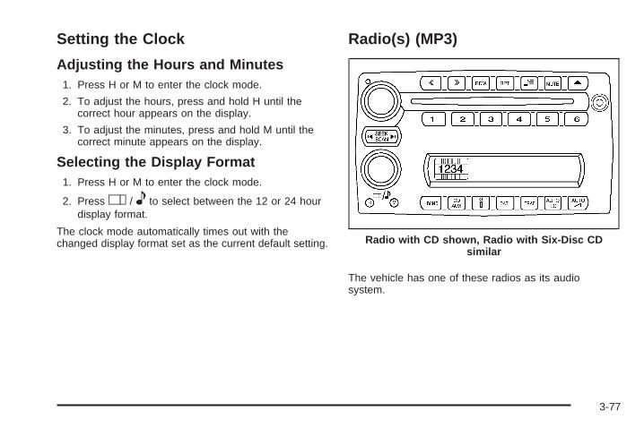
Setting the Clock
Adjusting the Hours and Minutes1. Press H or M to enter the clock mode.
2. To adjust the hours, press and hold H until thecorrect hour appears on the display.
3. To adjust the minutes, press and hold M until thecorrect minute appears on the display.
Selecting the Display Format1. Press H or M to enter the clock mode.
2. Press O / e to select between the 12 or 24 hourdisplay format.
The clock mode automatically times out with thechanged display format set as the current default setting.
Radio(s) (MP3)
The vehicle has one of these radios as its audiosystem.
Radio with CD shown, Radio with Six-Disc CDsimilar
3-77
Radio Data System (RDS)The audio system has a Radio Data System (RDS).RDS features are available for use only on FM stationsthat broadcast RDS information.
With RDS, the radio can do the following:
• Seek to stations broadcasting the selected type ofprogramming
• Receive announcements concerning local andnational emergencies
• Display messages from radio stations
• Seek to stations with traffic announcements
This system relies upon receiving specific informationfrom these stations and only works when the informationis available. In rare cases, a radio station can broadcastincorrect information that causes the radio featuresto work improperly. If this happens, contact the radiostation.
While the radio is tuned to an RDS station, the stationname or call letters display. RDS stations can alsoprovide the time of day, a program type (PTY) for currentprogramming, and the name of the program beingbroadcast.
Playing the Radio
Top Knob (Power/Volume): Press to turn the systemon and off. Turn clockwise or counterclockwise toincrease or to decrease the volume.
4 (Information): For RDS, press to change whatdisplays while using RDS. The display options arestation name, RDS station frequency, PTY (programtype), and the name of the program (if available).
For XM™ (if equipped), press while in XM mode toretrieve four different categories of information related tothe current song or channel: Artist, Song Title,Category or PTY, Channel Number/Channel Name.
To change the default on the display, press until thedesired display appears, then hold for two seconds.The radio produces one beep and the selected displaybecomes the default.
AUTO n (Automatic Volume): Automatic volumeadjusts the audio system automatically to make upfor road and wind noise while driving, by increasing thevolume as the vehicle speed increases.
3-78
Set the volume at the desired level. Press this button toselect AUTO VOLUME MIN (minimum), AUTO VOLUMEMED (medium), or AUTO VOLUME MAX (maximum).Each higher setting provides more volume compensationat faster vehicle speeds. To turn automatic volume off,press this button until AUTO VOLUME OFF displays.
MUTE: Press to silence the system. Press again to turnthe sound on.
This button is not available on the Radio withSix-Disc CD.
Finding a Station
BAND: Press to switch between FM1, FM2, AM, orXM1 or XM2 (if equipped). The selection displays.
O / e (Tune): Turn to select radio stations.
t SEEK u: Press the arrows to go to the previous orto the next station and stay there.
The radio seeks stations only with a strong signal thatare in the selected band.
t SCAN u: Press and hold either arrow fortwo seconds until FREQUENCY SCAN displays.The radio goes to a station, plays for a few seconds,then goes to the next station. Press either arrow again tostop scanning.
To scan preset stations, press and hold either arrow forfour seconds until PRESET SCAN displays. The radiogoes to the next preset station, plays for a few seconds,then goes to the next preset station. Press either arrowagain or one of the pushbuttons to stop scanning presets.
The radio scans stations only with a strong signal that arein the selected band.
Setting Preset StationsUp to 30 stations (six FM1, six FM2, and six AM,six XM1 and six XM2 (if equipped)), can be programmedon the six numbered pushbuttons, by performing thefollowing steps:
1. Turn the radio on.
2. Press BAND to select FM1, FM2, AM, or XM1 orXM2 (if equipped).
3. Tune in the desired station.
4. Press AUTO EQ to select the equalization.
5. Press and hold one of the six numberedpushbuttons until a beep sounds. When thatnumbered pushbutton is pressed, the station thatwas set, returns and the equalization that wasselected is stored for that pushbutton.
6. Repeat the steps for each pushbutton.
3-79
Setting the Tone (Bass/Treble)
O / e (Bass/Treble): Press to select BASS orTREBLE. Turn to increase or to decrease. If a station isweak or has static, decrease the treble.
To adjust the bass and treble to the middle position,press and hold when the tone control is on the display.The level changes to the middle position.
To adjust all tone and speaker controls to the middleposition, press and hold when no tone or speaker controldisplays. AUDIO SETTINGS CENTERED displays.
AUTO EQ (Automatic Equalization): Press to selectcustomized equalization settings designed for country,custom, classical, pop, rock, jazz, and talk. SelectingCUSTOM or changing bass or treble, returns the EQ tothe manual bass and treble settings.
The radio saves separate AUTO EQ settings for eachpreset and source.
Adjusting the Speakers (Balance/Fade)
O / e (Balance/Fade): To adjust the balancebetween the right and the left speakers, press untilBALANCE displays. Turn to move the sound toward theright or the left speakers.
To adjust the fade between the front and the rearspeakers, press until FADE displays. Turn to move thesound toward the front or the rear speakers.
To adjust the balance and fade to the middle position,press and hold when the speaker control displays.The level changes to the middle position.
To adjust all tone and speaker controls to the middleposition, press and hold when no tone or speaker controldisplays. AUDIO SETTINGS CENTERED displays.
3-80

Finding a Category Station(RDS and XM)To select and find a desired category perform thefollowing:
1. Press the CAT (category) button. The last selectedcategory displays.
2. Turn the O / e knob to select the category.
3. Once the desired category is displayed, press eitherSEEK arrow to go to a station within this category.SEEKING CATEGORY appears on the display whilethe radio is searching for a station. The radio stops atthe first station broadcasting with this category.
4. To go to another station within that category, pressthe CAT button to display the category, then presseither SEEK arrow.
If both category and traffic are on, the radio searchesfor stations with the selected category and trafficannouncements. This function does not work with XM.
If the radio cannot find the desired category, NONEdisplays and the radio returns to the last station that wason. This function does not work with XM.
SCAN: Scan the stations within a category byperforming the following:
1. Press the CAT button. The last selected categorydisplays.
2. Turn the O / e knob to select the category.
3. Once the desired category is displayed, press andhold either SCAN arrow until a beep sounds andSCAN CATEGORY displays. The radio beginsscanning the stations in the category.
4. Press either SCAN arrow to stop scanning.
If both category and TRAF (traffic) are on, the radioscans for stations with the selected category and trafficannouncements.
RDS Messages
ALERT!: Alert warns of local or national emergencies.When an alert announcement comes on the current radiostation, ALERT! displays. The announcement should beheard, even if the volume is low or a CD is playing. If aCD is playing, play stops during the announcement. Alertannouncements cannot be turned off.
ALERT! is not affected by tests of the emergencybroadcast system. This feature is not supported by allRDS stations.
3-81
4 (INFO – Information): If the current station has amessage, INFO displays. Press to see the message.The message can display the artist, song title, callin phone numbers, etc.
If the entire message is not displayed, parts of themessage appears every three seconds. To scroll throughthe message, press and release this button. A new groupof words display after every press of the button. Once thecomplete message displays, INFO disappears from thedisplay until another new message is received. The lastmessage can display by pressing this button. The lastmessage stays on the display until a new message isreceived or you turn to a different station.
When a message is not available from a station,NO INFO displays.
TRAF (TA – Traffic): TA displays if a tuned stationbroadcasts traffic announcements.
If a station does not broadcast traffic announcements,press the TRAF button. The radio seeks to a station thatdoes. When a station is found, the radio stops seekingand TA displays. If no station is found that broadcaststraffic announcements, NO TRAFFIC displays.
The radio plays the traffic announcement even if thevolume is low. The radio interrupts the play of a CD ifthe last tuned station broadcasts traffic announcements.
If TA displays, press the TRAF button to turn off thetraffic announcements.
This function does not apply to XM Satellite RadioService.
Radio Messages
CAL ERR (Calibration Error): The audio system hasbeen calibrated for the vehicle from the factory. IfCAL ERR displays, it means that the radio has not beenconfigured properly for the vehicle and must bereturned to your dealer/retailer for service.
LOCKED: This message displays when theTHEFTLOCK® system has locked up. Take the vehicleto your dealer/retailer for service.
If any error occurs repeatedly or if an error cannot becorrected, contact your dealer/retailer. If the radiodisplays an error message, write it down and provide itto your dealer/retailer when reporting the problem.
3-82
XM Satellite Radio ServiceXM is a satellite radio service that is based in the48 contiguous United States and 10 Canadian provinces.XM Satellite Radio has a wide variety of programmingand commercial-free music, coast-to-coast, and indigital-quality sound. During your trial or when yousubscribe, you will get unlimited access to XM RadioOnline for when you are not in the vehicle. A service feeis required to receive the XM service. For moreinformation, contact XM at xmradio.com or call1-800-929-2100 in the U.S. and xmradio.ca or call1-877-438-9677 in Canada.
Radio Messages for XM OnlySee XM Radio Messages on page 3-92 later in thissection for further detail.
Playing a CD (Single CD Player)Insert a CD partway into the slot, label side up. Theplayer pulls it in and the CD should begin playing.
If the ignition or radio is turned off with a CD in theplayer, it stays in the player. When the ignition or radiois turned on, the CD starts playing where it stopped,if it was the last selected audio source.
When a CD is inserted, CD and the CD symboldisplays. As each new track starts to play the tracknumber displays.
The CD player can play the smaller 3 inch (8 cm) singleCDs with an adapter ring. Full-size CDs and thesmaller CDs are loaded in the same manner.
Playing a CD(s) (Six-Disc CD Player)
M (Load): Press to load CDs into the CD player.This CD player holds up to six CDs.
To insert one CD, do the following:
1. Turn the ignition on.
2. Press and release the load button.
3. When INSERT CD # displays, load a CD. Insert theCD partway into the slot, label side up. The playerpulls the CD in.
To insert multiple CDs, do the following:
1. Turn the ignition on.
2. Press and hold the load button for two seconds.A beep sounds and LOAD ALL DISC displays.
3. When INSERT CD # displays, load a CD. Insert theCD partway into the slot, label side up. The playerpulls the CD in.Once the CD is loaded, wait for INSERT CD # todisplay, then load the next CD. The CD player takesup to six CDs. Do not try to load more than six.
3-83
To load more than one CD but less than six, completeSteps 1 through 3. When finished loading CDs,press this button to cancel the loading function. Theradio begins to play the last CD loaded.
If more than one CD has been loaded, a number foreach CD displays.
Playing a Specific Loaded CDA number displays for every CD that is loaded into theplayer. To play a specific CD press the numberedpushbutton that corresponds to the CD.
Care of CDsIf playing a CD-R, the sound quality can be reduced dueto CD-R quality, the method of recording, the quality ofthe music that has been recorded, and the way the CD-Rhas been handled. Handle them carefully. Store CD-R(s)in their original cases or other protective cases and awayfrom direct sunlight and dust. The CD player scans thebottom surface of the disc. If the surface of a CD isdamaged, such as cracked, broken, or scratched, the CDdoes not play properly or not at all. Do not touch thebottom side of a CD while handling it; this could damagethe surface. Pick up CDs by grasping the outer edges orthe edge of the hole and the outer edge.
If the surface of a CD is soiled, take a soft, lint free clothor dampen a clean, soft cloth in a mild, neutral detergentsolution mixed with water, and clean it. Make sure thewiping process starts from the center to the edge.
Care of the CD and DVD PlayerDo not add any label to a CD, it could get caught in theCD or DVD player. If a CD is recorded on a personalcomputer and a description label is needed, try labelingthe top of the recorded CD with a marking pen.
The use of CD lens cleaners for CDs is not advised,due to the risk of contaminating the lens of the CD opticswith lubricants internal to the CD or DVD playermechanism.
Notice: If a label is added to a CD, or more thanone CD is inserted into the slot at a time, or anattempt is made to play scratched or damaged CDs,the CD player could be damaged. While using theCD player, use only CDs in good condition withoutany label, load one CD at a time, and keep theCD player and the loading slot free of foreignmaterials, liquids, and debris.
3-84
If an error displays, see “CD Messages” later in thissection.
X (Eject): Press to eject CD(s). Eject can be activatedwith either the ignition or radio off.
To eject the CD that is currently playing, press andrelease.
To eject multiple CDs, do the following:
1. Press and hold eject for two seconds. A beepsounds and EJECT ALL DISCS displays.
2. When REMOVE DISC displays, the CD ejects andcan be removed.To stop ejecting the CDs, press the load or theeject button.
If the CD is not removed, after 25 seconds, the CDautomatically pulls it back into the player. If CDis pushed back into the player, before 25 seconds, theplayer senses an error and tries to eject the CDseveral times before stopping.
Do not repeatedly press the X button to eject a CDafter pushing it in manually because the eject timer resetsto 25 seconds after each press of the button. The CD willeject only after an uninterrupted 25 seconds occurs.
O / e (Tune): Turn to go to the next or previoustrack.
{ (Fast Reverse): Press and hold to reverse withinthe current track.
| (Fast Forward): Press and hold to fast forwardthrough the current track.
RDM (Random): Press to hear the tracks in random,rather than sequential order, on one CD or all ofthe loaded CDs.
To use random, do one of the following:
• Press and release this button until RANDOM DISCPLAY displays, to play the tracks on a CD inrandom order.
• Press and release this button until RANDOM ALLDISCS displays, to play the tracks on all of theCDs that are loaded in random order.
To turn off random play, press and release the RDMbutton until RANDOM OFF displays.
3-85
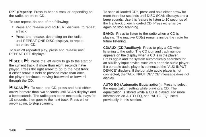
RPT (Repeat): Press to hear a track or depending onthe radio, an entire CD.
To use repeat, do one of the following:
• Press and release until REPEAT displays, to repeata track.
• Press and release, depending on the radio,until REPEAT ONE DISC displays, to repeatan entire CD.
To turn off repeated play, press and release untilREPEAT OFF displays.
t SEEK u: Press the left arrow to go to the start ofthe current track, if more than eight seconds haveplayed. Press the right arrow to go to the next track.If either arrow is held or pressed more than once,the player continues moving backward or forwardthrough the CD.
t SCAN u: To scan one CD, press and hold eitherarrow for more than two seconds until SCAN displays anda beep sounds. The radio goes to the next track, plays for10 seconds, then goes to the next track. Press eitherarrow again, to stop scanning.
To scan all loaded CDs, press and hold either arrow formore than four seconds until DISC SCAN displays and abeep sounds. Use this feature to listen to 10 seconds ofthe first track of each loaded CD. Press either arrowagain, to stop scanning.
BAND: Press to listen to the radio when a CD isplaying. The inactive CD(s) remains inside the radio forfuture listening.
CD/AUX (CD/Auxiliary): Press to play a CD whenlistening to the radio. The CD icon and track numberappears on the display when a CD is in the player.Press again and the system automatically searches foran auxiliary input device, such as a portable audio player.If a portable audio player is connected the “AUX INPUTDEVICE” displays. If the portable audio player is notconnected, the “AUX INPUT DEVICE” message does notdisplay.
AUTO EQ (Automatic Equalization): Press to selectthe equalization setting while playing a CD. Theequalization is stored while a CD is played. For moreinformation on AUTO EQ, see “AUTO EQ” listedpreviously in this section.
3-86
Playing an MP3 CD-R DiscThe vehicle’s radio system has the MP3 feature that iscapable of playing an MP3 CD-R disc. For moreinformation on how to play an MP3 CD-R disc, seeUsing an MP3 on page 3-89 later in this section.
Using R (Song List) Mode (Single CDand Six-Disc CD)This feature is capable of saving 20 track selections.To save tracks into the song list feature, performthe following steps:
1. Turn the CD player on and load it with at leastone CD.
2. Check to see that the CD player is not in songlist mode. S-LIST (sound list) should not display.If S-LIST is present, press the song list buttonto turn it off.
3. Select the desired CD by pressing the numberedpushbutton and then use the left SEEK arrow orturn the O / e knob to locate the track to besaved. The track begins to play.
4. Press and hold the R button to save the track intomemory. When song list is pressed, one beepsounds. ADDED SONG displays.
5. Repeat Steps 3 and 4 for saving other selections.
SONGLIST FULL displays if more than 20 selections aresaved.
To play the song list, press the R button. The recordedtracks begins to play in the order they were saved.
Seek through the song list by using the SEEK arrows.Seeking past the last saved track returns to the firstsaved track.
To delete tracks from the song list, perform the followingsteps:
1. Turn the CD player on.
2. Press the R button to turn song list on. S-LISTdisplays.
3. Press either SEEK arrow or turn the O / e knobto select the desired track to be deleted.
4. Press and hold the R button for two seconds.Release this button when SONG REMOVEDdisplays.
3-87
After a track has been deleted, the remaining tracks aremoved up the list. When another track is added tothe song list, the track is added to the end of the list.
To delete the entire song list, perform the followingsteps:
1. Turn the CD player on.
2. Press the R button to turn song list on. S-LISTdisplays.
3. Press and hold the R button for more thanfour seconds. Two beeps will sound. SONGLISTEMPTY displays indicating the song list hasbeen deleted.
If a CD is ejected, and the song list contains savedtracks from that CD, those tracks are automaticallydeleted from the song list. Additional tracks saved to thesong list are added to the bottom of the list.
To end song list mode, press the song list button. Onebeep sounds and S-LIST is removed from the display.
CD Messages
CHECK CD: If this message displays and/or the CDcomes out, it could be for one of the following reasons:
• It is very hot. When the temperature returns tonormal, the CD should play.
• You are driving on a very rough road. When theroad becomes smoother, the CD should play.
• The CD is dirty, scratched, wet, or upside down.
• The air is very humid. If so, wait about an hour andtry again.
• There may have been a problem while burningthe CD.
• The label may be caught in the CD player.
If the CD is not playing correctly, for any other reason,try a known good CD.
If any error occurs repeatedly or if an error cannot becorrected, contact your dealer/retailer. If the radiodisplays an error message, write it down and provide itto your dealer/retailer when reporting the problem.
3-88
Using the Auxiliary Input JackThe radio system has an auxiliary input jack located onthe upper right side of the faceplate. This is not an audiooutput; do not plug the headphone set into the frontauxiliary input jack. However, an external audio devicesuch as an iPod, laptop computer, MP3 player, CDchanger, or cassette tape player, etc. can be connectedto the auxiliary input jack for use as another source foraudio listening.
Drivers are encouraged to set up any auxiliary devicewhile the vehicle is in PARK (P). See Defensive Drivingon page 4-2.
To use a portable audio player, connect a 3.5 mm(1/8 inch) cable to the radio’s front auxiliary input jack.When a device is connected, the radio displays AUXINPUT DEVICE and begins playing audio fromthat device.
Top Knob (Power/Volume): Turn clockwise orcounterclockwise to increase or decrease the volume ofthe portable player. Additional volume adjustmentsmight need to be made from the portable device.
BAND: Press to listen to the radio while a portableaudio device is playing. The portable audio devicecontinues playing, so you might want to stop it orturn it off.
CD/AUX (CD/Auxiliary): Press to play a CD or otheroptional remote audio features, while a portableaudio device is playing. If the external audio device isdisconnected from the faceplate, the radio automaticallyreturns to the last station that was set.
Using an MP3
MP3 CD-R Disc
MP3 FormatIf you burn your own MP3 disc on a personal computer:
• Make sure the MP3 files are recorded on aCD-R disc.
• Do not mix standard audio and MP3 files onone disc.
• Make sure playlists have a .mp3 or .wpl extension,other file extensions may not work.
3-89

• Files can be recorded with a variety of fixed orvariable bit rates. Song title, artist name, and albumare available for display by the radio whenrecorded using ID3 tags version 1 and 2.
• Create a folder structure that makes it easy to findsongs while driving. Organize songs by albumsusing one folder for each album. Each folderor album should contain 18 songs or less.
• Make sure to finalize the disc when burning an MP3disc, using multiple sessions. It is usually better toburn the disc all at once.
• Do not use CD-RW discs.
• Do not use colored discs.
The player is able to read and play a maximum of50 folders, 50 playlists, 10 sessions, and 255 files. Longfile names, folder names, or playlist names could usemore disc memory space than necessary. To conservespace on the disc, minimize the length of the file, folder,or playlist names. You can also play an MP3 CD that wasrecorded using no file folders. The system can support upto 11 folders in depth, though, keep the depth of thefolders to a minimum in order to keep down thecomplexity and confusion in trying to locate a particularfolder during playback. If a CD contains more than themaximum of 50 folders, 50 playlists, 10 sessions, and255 files the player lets you access and navigate up tothe maximum, but all items over the maximum areignored.
Root DirectoryThe root directory is treated as a folder. If the rootdirectory has compressed audio files, the directory isdisplayed as F1 ROOT. All files contained directly underthe root directory are accessed prior to any rootdirectory folders. However, playlists (Px) are alwaysaccessed before root folders or files.
Empty Directory or FolderIf a root directory or a folder exists somewhere in thefile structure that contains only folders/subfolders and nocompressed files directly beneath them, the playeradvances to the next folder in the file structurethat contains compressed audio files. The empty folderdoes not display.
No FolderWhen the CD contains only compressed files, the fileswill be located under the root folder. The next andprevious folder functions do not function on a CD that wasrecorded without folders or playlists. When displaying thename of the folder the radio displays ROOT.
When the CD contains only playlists and compressedaudio files, but no folders, all files are located under theroot folder. The folder down and the folder up buttonssearch playlists (Px) first and then go to the root folder.When the radio displays the name of the folder theradio displays ROOT.
3-90
Order of PlayTracks are played in the following order:
• Play begins from the first track in the first playlistand continues sequentially through all tracks ineach playlist. When the last track of the last playlisthas played, play continues from the first track ofthe first playlist.
• If the CD does not contain any playlists, then playbegins from the first track under the root directory.When all tracks from the root directory have played,play continues from files according to their numericallisting. After playing the last track from the last folder,play begins again at the first track of the first folder orroot directory.
When play enters a new folder, the display does notautomatically show the new folder name unlessthe folder mode was chosen as the default display. Seethe information button later in this section for moreinformation. The new track name displays.
File System and NamingThe song name that displays is the song name that iscontained in the ID3 tag. If the song name is not presentin the ID3 tag, then the radio displays the file namewithout the extension (such as .mp3) as the track name.
Track names longer than 32 characters or four pagesare shortened. Parts of words on the last page oftext and the extension of the filename does not display.
Preprogrammed PlaylistsPreprogrammed playlists that were created usingWinAmp™, MusicMatch™, or Real Jukebox™ softwarecan be accessed, however, they cannot be editedusing the radio. These playlists are treated as specialfolders containing compressed audio song files.
Playing an MP3Insert a CD-R partway into the slot (Single CD Player),or press the load button and wait for the message toinsert disc (Six-Disc CD Player), label side up. Theplayer pulls it in, and the CD-R should begin playing.
{ (Previous Folder): Press to go to the first track inthe previous folder. Press and hold to reverse throughthe current track.
| (Next Folder): Press to go to the first track inthe next folder. Press and hold to fast forward thecurrent track.
3-91

RDM (Random): Press to hear the tracks in random,rather than sequential order, on one CD, one folder,or all of the loaded CDs.
To use random, do one of the following:
• Press and release until RANDOM DISC PLAYdisplays, to play the tracks on a CD in random order.
• Press and release until RANDOM FOLDER displays,to play the tracks in a folder in random order.
• Press and release until RANDOM ALL DISCSdisplays, to play the tracks on all of the CDs that areloaded in random order.
Press and release the RDM button until RANDOM OFFdisplays, to turn off random play.
RPT (Repeat): Press to hear a track, CD, or a folderover again.
To use repeat, do one of the following:
• Press and release until REPEAT displays, to repeata track.
• Press and release until REPEAT ONE DISCdisplays, to repeat a CD.
• Press and release until REPEAT FOLDER displays,to repeat a folder.
Press and release the RPT button until REPEAT OFFdisplays, to turn off repeated play.
4 (Information): Press to display the artist name andalbum contained in the ID3 tag.
XM Radio Messages
xL (Explicit Language Channels): Thesechannels, or any others, can be blocked by calling1-800-852-XMXM (9696).
Updating: The encryption code in the receiver is beingupdated, and no action is required. This processshould take no longer than 30 seconds.
No Signal: The system is functioning correctly, but thevehicle is in a location that is blocking the XM signal.When the vehicle is moved into an open area, the signalshould return.
Loading XM: The audio system is acquiring andprocessing audio and text data. No action is needed.This message should disappear shortly.
CH Off Air: This channel is not currently in service.Tune in to another channel.
3-92
CH Unauth: This channel is blocked or cannot bereceived with your XM Subscription package.
CH Unavail: This previously assigned channel is nolonger assigned. Tune to another station. If this stationwas one of the presets, choose another station forthat preset button.
No Info: No artist, song title, category, or textinformation is available at this time on this channel. Thesystem is working properly.
Not Found: There are no channels available for theselected category. The system is working properly.
XM Locked: The XM receiver in the vehicle may havepreviously been in another vehicle. For securitypurposes, XM receivers cannot be swapped betweenvehicles. If this message is received after havingthe vehicle serviced, check with your dealer/retailer.
Radio ID: If tuned to channel 0, this message willalternate with the XM Radio 8 digit radio ID label. Thislabel is needed to activate the service.
Unknown: If this message is received when tuned tochannel 0, there may be a receiver fault. Consultwith your dealer/retailer.
Chk XMRcvr: If this message does not clear within ashort period of time, the receiver may have a fault.Consult with your dealer/retailer.
Rear Seat Entertainment (RSE)SystemVehicles with an RSE system have a video displayscreen, auxiliary inputs, two sets of wirelessheadphones, a DVD player, and a remote control.
Before DrivingThe RSE is designed for rear seat passengers only.The driver cannot safely view the video screenwhile driving and should not try to do so.
Normal operation could be limited under extremely lowor high temperatures in order to protect the systemfrom damage. Operate the RSE system under normal orcomfortable cabin temperature ranges.
3-93
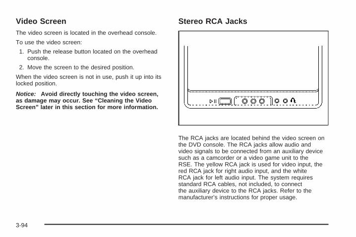
Video ScreenThe video screen is located in the overhead console.
To use the video screen:
1. Push the release button located on the overheadconsole.
2. Move the screen to the desired position.
When the video screen is not in use, push it up into itslocked position.
Notice: Avoid directly touching the video screen,as damage may occur. See “Cleaning the VideoScreen” later in this section for more information.
Stereo RCA Jacks
The RCA jacks are located behind the video screen onthe DVD console. The RCA jacks allow audio andvideo signals to be connected from an auxiliary devicesuch as a camcorder or a video game unit to theRSE. The yellow RCA jack is used for video input, thered RCA jack for right audio input, and the whiteRCA jack for left audio input. The system requiresstandard RCA cables, not included, to connectthe auxiliary device to the RCA jacks. Refer to themanufacturer’s instructions for proper usage.
3-94
To use the auxiliary audio and video inputs, connect anexternal auxiliary device such as a camcorder to theRCA jacks and turn on both the auxiliary device powerand the power on the front of the RSE player.
If a disc is present when the RSE power is turned on,the player automatically begins playing the disc.Press the AUX button on the remote control or theDVD AUX button on the DVD player faceplate to switchthe system between the DVD player and the auxiliarydevice. See “DVD Player” and “Remote Control” later inthis section for more information.
Parental Control
wj (Parental Control): This button is located behindthe video screen next to the auxiliary and headphonejacks. Press wj while using RSA, or when a DVD or CDis playing to blank the video screen and to mute theaudio. The power indicator lights on the DVD playerflashes. The parental control also disables all other buttonoperations from the remote control and the DVD player,except for the eject button. Press wj again to restoreoperation of the RSA, DVD player, and remote control.
wj can also be used to turn the DVD player power onand automatically resume play if the vehicle is on and adisc is in the player. If a disc is not in the player then thesystem powers up in auxiliary mode.
Audio OutputAudio from the DVD player or auxiliary inputs can beheard through the following sources:
• Vehicle Speakers
• Wireless Headphones
• Wired Headphones (not included)
Vehicle SpeakersOnly one audio source can be heard through thevehicle’s speakers at a time.
The RSE system or an auxiliary device can be heardthrough all of the vehicle’s speakers when the followingoccurs:
• A DVD or auxiliary device is playing
• The front audio system is on and the CD AUXbutton is pressed to enable the RSE system
DVD appears on the radio display when the RSEsystem is on.
To turn the vehicles speakers on and off, press theCD AUX button on the radio. The audio from the RSEsystem can be heard through the wireless headphonesand the vehicles speakers at the same time. Thevolume on the radio varies when switching between theradio, CD, DVD, MP3, or an auxiliary device.
3-95
Headphones
Notice: Do not store the headphones in heat ordirect sunlight. This could damage the headphonesand repairs will not be covered by your warranty.Storage in extreme cold can weaken the batteries.Keep the headphones stored in a cool, dry place.
Wireless HeadphonesThe RSE system may include two sets of wirelessheadphones (batteries may be included with theheadphone sets).
The wireless headphones have an ON/OFF switch, achannel select switch, and a volume control. To use theheadphones, turn the ON/OFF switch to ON. Anindicator light on the headphones come on. If the lightdoes not come on, the batteries might need to bereplaced. See “Battery Replacement” later in this sectionfor more information. Switch the headphones to OFFwhen not in use.
The headphones shut off automatically to save thebattery power if the RSE system is off or if theheadphones are out of range of the transmitters for more
than three minutes. The transmitters are located next tothe DVD faceplate. If the person using the headphonesmoves too far forward or steps out of the vehicle, theheadphones lose the audio signal.
DVD and auxiliary audio are always found on channel(CHA or CH1) of the wireless headphones. RSA audio isdedicated to CHB or CH2 of the wireless headphones.
To adjust the volume on the wireless headphones,use the volume control located on the headphones.
If there is a decreased audio signal during CD, MP3, orDVD play, there could be a low hissing noise throughthe speakers and/or headphones. If the hissing sound inthe wireless headphones seems excessive, makesure that the headphone batteries are fully charged.Some amount of hissing is normal.
Both sets of rear seat headphones could include foamear pads that can be replaced.
These foam ear pads can become worn or damaged ifthey are not handled or stored properly. They canbe replaced separately from the headphone set. Seeyour dealer/retailer for more information.
3-96
Battery ReplacementTo change the batteries on the headphones:
1. Turn the screw to loosen the battery door locatedon the left side of the headphones, then slide thebattery door open.
2. Replace the two batteries in the compartment.Make sure that they are installed correctly using thediagram on the inside of the battery compartment.
3. Replace the battery door and tighten the doorscrew.
If the headphones are to be stored for a long period oftime, remove the batteries, and keep them in a cool,dry place.
Wired HeadphonesThere is a right and left wired headphone jack locatedbehind the video screen next to the auxiliary jacks.
The wired headphones work as follows:
• DVD on / RSA off: The wired headphones playsRSE audio.
• DVD off / RSA on: The wired headphones playsRSA audio.
• DVD on / RSA on: The wired headphones playsRSA audio.
DVD PlayerThe DVD player is located in the overhead console andcan be controlled by the buttons on the DVD playerand/or by the buttons on the remote control. See “RemoteControl” later in this section for more information.
The RSE system DVD player is only compatible withDVDs of the appropriate region code for the country thatthe vehicle was sold. The DVD region code is printedon the jacket of most DVDs.
The player is capable of playing the following mediaformats:
• DVD (single and dual layer)
• DVD+R/RW
• DVD-R/RW
• DVD-ROM with MP3
• DVD-ROM with WMA
• CD-DA
• CD-R/RW
• CD-ROM with MP3
• CD-ROM with WMA
• Enhanced CD
• SACD (CD player only)
3-97
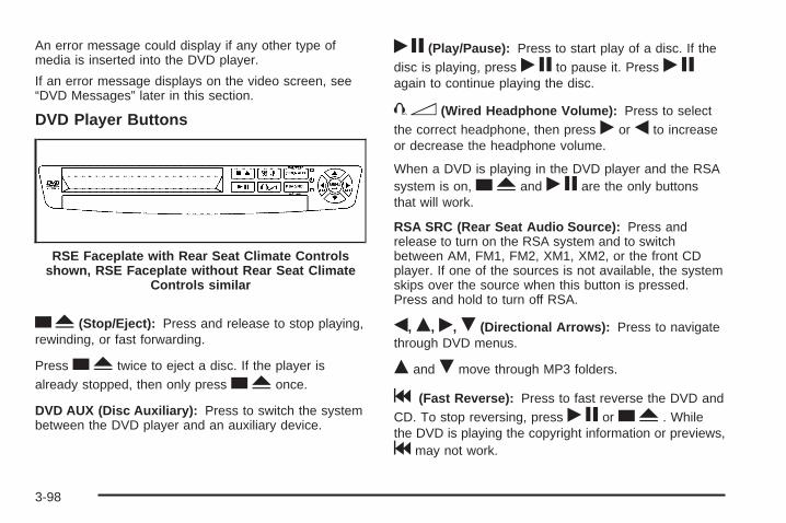
An error message could display if any other type ofmedia is inserted into the DVD player.
If an error message displays on the video screen, see“DVD Messages” later in this section.
DVD Player Buttons
cY (Stop/Eject): Press and release to stop playing,rewinding, or fast forwarding.
Press cY twice to eject a disc. If the player isalready stopped, then only press cY once.
DVD AUX (Disc Auxiliary): Press to switch the systembetween the DVD player and an auxiliary device.
rj (Play/Pause): Press to start play of a disc. If thedisc is playing, press r j to pause it. Press r jagain to continue playing the disc.
43 (Wired Headphone Volume): Press to selectthe correct headphone, then press r or q to increaseor decrease the headphone volume.
When a DVD is playing in the DVD player and the RSAsystem is on, cY and r j are the only buttonsthat will work.
RSA SRC (Rear Seat Audio Source): Press andrelease to turn on the RSA system and to switchbetween AM, FM1, FM2, XM1, XM2, or the front CDplayer. If one of the sources is not available, the systemskips over the source when this button is pressed.Press and hold to turn off RSA.
q, Q, r, R (Directional Arrows): Press to navigatethrough DVD menus.
Q and R move through MP3 folders.
g (Fast Reverse): Press to fast reverse the DVD andCD. To stop reversing, press r j or cY . Whilethe DVD is playing the copyright information or previews,g may not work.
RSE Faceplate with Rear Seat Climate Controlsshown, RSE Faceplate without Rear Seat Climate
Controls similar
3-98
l (Fast Forward): Press to fast forward the DVD andCD. To stop forwarding, press r j or cY . Whilethe DVD is playing the copyright information or previews,l may not work.
MENU (Disc): Press to view the main DVD menu. Themenu is different on every disc. Use q , Q , r , orR to move the cursor around the menu. After making aselection, press r .
r (Enter/Select): Press to select the choice that ishighlighted in any menu.
z (Display Control Button): Press to open the RSEOn-Screen Display (OSD) menus to adjust the color,tint, brightness, contrast, and display modes.
• For vehicles without rear seat climate control, zcan take the place of 9C .
• For vehicles with rear seat climate control, z isalso found on the remote control.
Playing a DiscTo play a disc, insert the disc with the label side up intothe loading slot. The DVD player continues loadingthe disc and the player automatically starts if the vehicleis in ACC/ACCESSORY, ON/RUN, or RAP.
If a disc is already in the player make sure that the DVDplayer is on, then press rj on the player faceplate oron the remote control. Press DVD AUX on the playerfaceplate, or CD AUX on the radio faceplate until RSEdisplays, to start playing a disc.
Some DVDs do not allow fast forwarding or skipping ofthe copyright information or previews. Some DVDsbegins playing after the previews have finished. If theDVD does not begin playing at the main title, refer to theon-screen instructions.
To stop playing a disc, press cY on the DVD playerfaceplate or the remote control.
To resume playback, press r j on the DVD playerfaceplate or the remote control. The movie shouldresume play from where it was last stopped if the dischas not been ejected.
If the disc has been ejected, the disc resumes play atthe beginning of the disc.
3-99
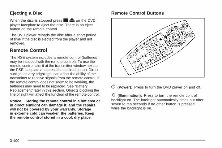
Ejecting a Disc
When the disc is stopped press cY on the DVDplayer faceplate to eject the disc. There is no ejectbutton on the remote control.
The DVD player reloads the disc after a short periodof time if the disc is ejected from the player and notremoved.
Remote ControlThe RSE system includes a remote control (batteriesmay be included with the remote control). To use theremote control, aim it at the transmitter window next tothe RSE faceplate and press the desired button. Directsunlight or very bright light can affect the ability of thetransmitter to receive signals from the remote control. Ifthe remote control does not seem to be working, thebatteries may need to be replaced. See “BatteryReplacement” later in this section. Objects blocking theline of sight will affect the function of the remote control.
Notice: Storing the remote control in a hot area orin direct sunlight can damage it, and the repairswill not be covered by your warranty. Storagein extreme cold can weaken the batteries. Keepthe remote control stored in a cool, dry place.
Remote Control Buttons
O (Power): Press to turn the DVD player on and off.
P (Illumination): Press to turn the remote controlbacklight on. The backlight automatically times out afterseven to ten seconds if no other button is pressedwhile the backlight is on.
3-100
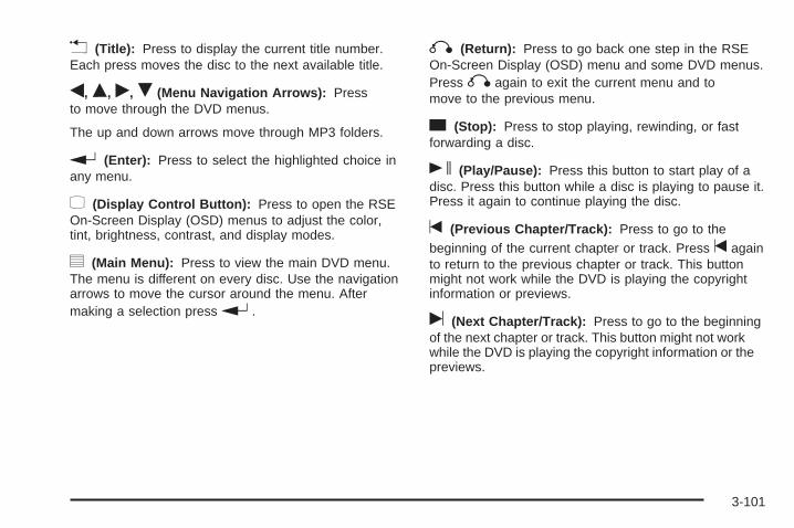
v (Title): Press to display the current title number.Each press moves the disc to the next available title.
q, Q, r, R (Menu Navigation Arrows): Pressto move through the DVD menus.
The up and down arrows move through MP3 folders.
r (Enter): Press to select the highlighted choice inany menu.
z (Display Control Button): Press to open the RSEOn-Screen Display (OSD) menus to adjust the color,tint, brightness, contrast, and display modes.
y (Main Menu): Press to view the main DVD menu.The menu is different on every disc. Use the navigationarrows to move the cursor around the menu. Aftermaking a selection press r .
q (Return): Press to go back one step in the RSEOn-Screen Display (OSD) menu and some DVD menus.Press q again to exit the current menu and tomove to the previous menu.
c (Stop): Press to stop playing, rewinding, or fastforwarding a disc.
s (Play/Pause): Press this button to start play of adisc. Press this button while a disc is playing to pause it.Press it again to continue playing the disc.
t (Previous Chapter/Track): Press to go to thebeginning of the current chapter or track. Press t againto return to the previous chapter or track. This buttonmight not work while the DVD is playing the copyrightinformation or previews.
u (Next Chapter/Track): Press to go to the beginningof the next chapter or track. This button might not workwhile the DVD is playing the copyright information or thepreviews.
3-101
r (Fast Reverse): Press to fast reverse the DVDand CD. To stop reversing, press r j or cY .This button might not work while the DVD is playing thecopyright information or the previews.
[ (Fast Forward): Press to fast forward the DVD andCD. To stop fast forwarding, press r j or cY .This button might not work while the DVD is playing thecopyright information or the previews.
e (Sound): Press to display the current audio track.Each press moves the DVD to the next languageor commentary. The format and content of this functionvary for each disc.
{ (Subtitles): Press to display the current subtitles.Each press of this button moves the DVD to thenext available subtitle option (English, Spanish, French,etc., if available). The format and content of thisfunction vary for each disc.
AUX (Auxiliary): Press this button to switch the systembetween the DVD player and an auxiliary source.
d (Camera): Press to display the current cameraangle on DVDs that have this feature. Each press movesthe DVD to the next available camera angle. Theformat and content of this function vary for each disc.
0 through 9 (Numeric Keypad): The numeric keypadprovides the capability of direct chapter or tracknumber selection.
\ (Clear): To clear all numeric inputs press withintwo seconds after entering a numeric selection.
} 10 (Multiple Digit Entries): Press before entering anumber greater than 9 to select a chapter or tracknumber greater than 9.
3-102
RSE On-Screen Display (OSD) MenuTo use the RSE OSD menu when using a DVD or anauxiliary device:
1. Press z on the remote control or on the DVDfaceplate, if the vehicle does not have rear seatclimate control.
2. Use q , Q , r , R and r to navigate thescreen.
This menu lets you select default preferences for videoformat, language preference, brightness, color, contrast,and tint. Not all DVDs support all the feature defaults inthe setup menus. If a feature is not supported, thedefaults are provided by the DVD media. To exit thismenu press z , or q on the remote control, orfaceplate if there is no rear seat climate control, or waitfor the menu to time out.
The default language selection applies to allfuture DVDs.
To use the RSE OSD menu when using a CD oran MP3:
1. Press z on the remote control or on the DVDfaceplate, if the vehicle does not have rear seatclimate control.
2. Use q , Q , r , R and r to navigate thescreen.
This menu lets you select default preferences forlanguage and playback settings. To exit this menu pressz , or q on the remote control, or faceplate if thereis no rear seat climate control, or wait for the menuto time out.
Battery ReplacementTo change the remote control batteries, do the following:
1. Slide the rear cover back on the remote control.
2. Replace the two batteries in the compartment. Makesure that they are installed correctly using thediagram on the inside of the battery compartment.
3. Replace the battery cover.
If the remote control is to be stored for a long period oftime, remove the batteries and keep them in a cool,dry place.
3-103
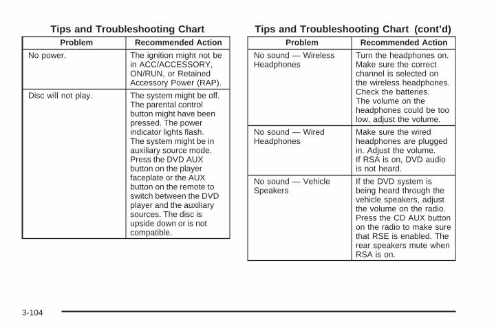
Tips and Troubleshooting ChartProblem Recommended Action
No power. The ignition might not bein ACC/ACCESSORY,ON/RUN, or RetainedAccessory Power (RAP).
Disc will not play. The system might be off.The parental controlbutton might have beenpressed. The powerindicator lights flash.The system might be inauxiliary source mode.Press the DVD AUXbutton on the playerfaceplate or the AUXbutton on the remote toswitch between the DVDplayer and the auxiliarysources. The disc isupside down or is notcompatible.
Tips and Troubleshooting Chart (cont’d)Problem Recommended Action
No sound — WirelessHeadphones
Turn the headphones on.Make sure the correctchannel is selected onthe wireless headphones.Check the batteries.The volume on theheadphones could be toolow, adjust the volume.
No sound — WiredHeadphones
Make sure the wiredheadphones are pluggedin. Adjust the volume.If RSA is on, DVD audiois not heard.
No sound — VehicleSpeakers
If the DVD system isbeing heard through thevehicle speakers, adjustthe volume on the radio.Press the CD AUX buttonon the radio to make surethat RSE is enabled. Therear speakers mute whenRSA is on.
3-104
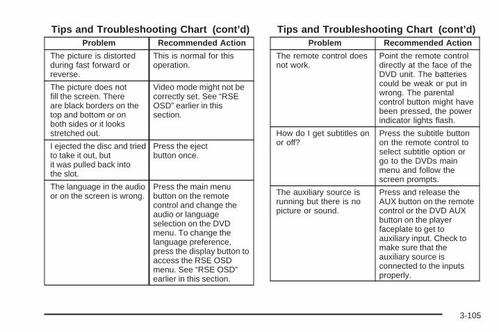
Tips and Troubleshooting Chart (cont’d)Problem Recommended Action
The picture is distortedduring fast forward orreverse.
This is normal for thisoperation.
The picture does notfill the screen. Thereare black borders on thetop and bottom or onboth sides or it looksstretched out.
Video mode might not becorrectly set. See “RSEOSD” earlier in thissection.
I ejected the disc and triedto take it out, butit was pulled back intothe slot.
Press the ejectbutton once.
The language in the audioor on the screen is wrong.
Press the main menubutton on the remotecontrol and change theaudio or languageselection on the DVDmenu. To change thelanguage preference,press the display button toaccess the RSE OSDmenu. See “RSE OSD”earlier in this section.
Tips and Troubleshooting Chart (cont’d)Problem Recommended Action
The remote control doesnot work.
Point the remote controldirectly at the face of theDVD unit. The batteriescould be weak or put inwrong. The parentalcontrol button might havebeen pressed, the powerindicator lights flash.
How do I get subtitles onor off?
Press the subtitle buttonon the remote control toselect subtitle option orgo to the DVDs mainmenu and follow thescreen prompts.
The auxiliary source isrunning but there is nopicture or sound.
Press and release theAUX button on the remotecontrol or the DVD AUXbutton on the playerfaceplate to get toauxiliary input. Check tomake sure that theauxiliary source isconnected to the inputsproperly.
3-105
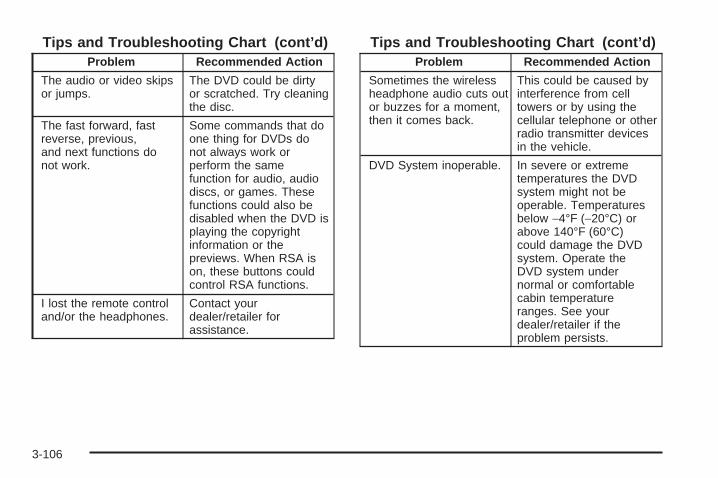
Tips and Troubleshooting Chart (cont’d)Problem Recommended Action
The audio or video skipsor jumps.
The DVD could be dirtyor scratched. Try cleaningthe disc.
The fast forward, fastreverse, previous,and next functions donot work.
Some commands that doone thing for DVDs donot always work orperform the samefunction for audio, audiodiscs, or games. Thesefunctions could also bedisabled when the DVD isplaying the copyrightinformation or thepreviews. When RSA ison, these buttons couldcontrol RSA functions.
I lost the remote controland/or the headphones.
Contact yourdealer/retailer forassistance.
Tips and Troubleshooting Chart (cont’d)Problem Recommended Action
Sometimes the wirelessheadphone audio cuts outor buzzes for a moment,then it comes back.
This could be caused byinterference from celltowers or by using thecellular telephone or otherradio transmitter devicesin the vehicle.
DVD System inoperable. In severe or extremetemperatures the DVDsystem might not beoperable. Temperaturesbelow −4°F (−20°C) orabove 140°F (60°C)could damage the DVDsystem. Operate theDVD system undernormal or comfortablecabin temperatureranges. See yourdealer/retailer if theproblem persists.
3-106
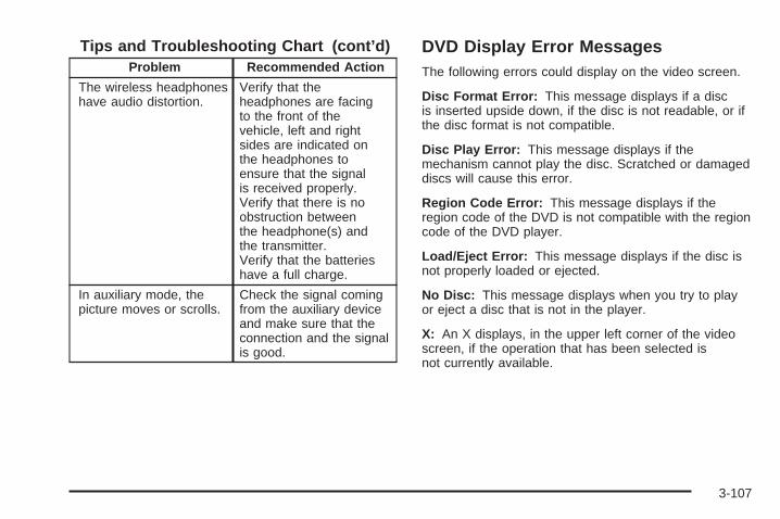
Tips and Troubleshooting Chart (cont’d)Problem Recommended Action
The wireless headphoneshave audio distortion.
Verify that theheadphones are facingto the front of thevehicle, left and rightsides are indicated onthe headphones toensure that the signalis received properly.Verify that there is noobstruction betweenthe headphone(s) andthe transmitter.Verify that the batterieshave a full charge.
In auxiliary mode, thepicture moves or scrolls.
Check the signal comingfrom the auxiliary deviceand make sure that theconnection and the signalis good.
DVD Display Error MessagesThe following errors could display on the video screen.
Disc Format Error: This message displays if a discis inserted upside down, if the disc is not readable, or ifthe disc format is not compatible.
Disc Play Error: This message displays if themechanism cannot play the disc. Scratched or damageddiscs will cause this error.
Region Code Error: This message displays if theregion code of the DVD is not compatible with the regioncode of the DVD player.
Load/Eject Error: This message displays if the disc isnot properly loaded or ejected.
No Disc: This message displays when you try to playor eject a disc that is not in the player.
X: An X displays, in the upper left corner of the videoscreen, if the operation that has been selected isnot currently available.
3-107
DVD DistortionVideo distortion can occur when operating cellularphones, scanners, CB radios, Global Position Systems(GPS)*, two-way radios, mobile fax, or walkie talkies.
It might be necessary to turn off the DVD player whenoperating one of these devices in or near the vehicle.
*Excludes the OnStar® System.
Cleaning the DVD PlayerWhen cleaning the outside DVD faceplate and buttons,use only a clean cloth dampened with clean water.
Cleaning the Video ScreenWhen cleaning the video screen, use only a clean clothdampened with clean water. Use care when directlytouching or cleaning the screen, as damage may result.
Rear Seat Audio (RSA)Vehicles with an RSA system allows rear seatpassengers to listen to and control any of the followingaudio sources: AM/FM tuner, front CD player, andXM™ Satellite Radio Service. However, the rear seatpassengers can only control the sources that thefront seat passengers are not listening to. For example,rear seat passengers can listen to a CD in the frontradio and control it while the front seat passengers listento the radio through the front speakers. The rear seatpassengers have control of the volume for eachset of headphones.
The front seat audio controls always have priority overthe RSA controls. If the front seat passengers switchthe source for the main radio to a remote source,the RSA is not able to control the remote source. RSAcan operate when the main radio is off.
3-108
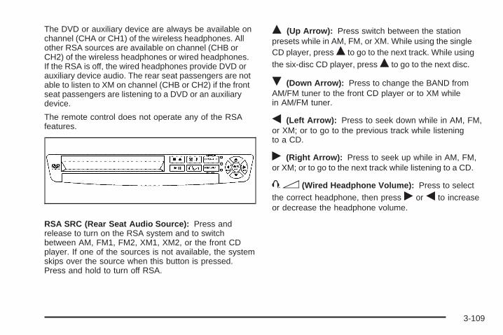
The DVD or auxiliary device are always be available onchannel (CHA or CH1) of the wireless headphones. Allother RSA sources are available on channel (CHB orCH2) of the wireless headphones or wired headphones.If the RSA is off, the wired headphones provide DVD orauxiliary device audio. The rear seat passengers are notable to listen to XM on channel (CHB or CH2) if the frontseat passengers are listening to a DVD or an auxiliarydevice.
The remote control does not operate any of the RSAfeatures.
RSA SRC (Rear Seat Audio Source): Press andrelease to turn on the RSA system and to switchbetween AM, FM1, FM2, XM1, XM2, or the front CDplayer. If one of the sources is not available, the systemskips over the source when this button is pressed.Press and hold to turn off RSA.
Q (Up Arrow): Press switch between the stationpresets while in AM, FM, or XM. While using the singleCD player, press Q to go to the next track. While usingthe six-disc CD player, press Q to go to the next disc.
R (Down Arrow): Press to change the BAND fromAM/FM tuner to the front CD player or to XM whilein AM/FM tuner.
q (Left Arrow): Press to seek down while in AM, FM,or XM; or to go to the previous track while listeningto a CD.
r (Right Arrow): Press to seek up while in AM, FM,or XM; or to go to the next track while listening to a CD.
43 (Wired Headphone Volume): Press to selectthe correct headphone, then press r or q to increaseor decrease the headphone volume.
3-109
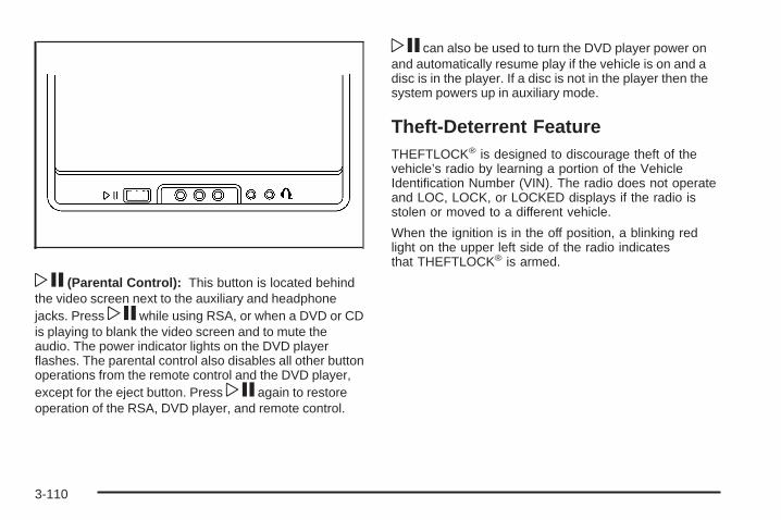
wj (Parental Control): This button is located behindthe video screen next to the auxiliary and headphonejacks. Press wj while using RSA, or when a DVD or CDis playing to blank the video screen and to mute theaudio. The power indicator lights on the DVD playerflashes. The parental control also disables all other buttonoperations from the remote control and the DVD player,except for the eject button. Press wj again to restoreoperation of the RSA, DVD player, and remote control.
wj can also be used to turn the DVD player power onand automatically resume play if the vehicle is on and adisc is in the player. If a disc is not in the player then thesystem powers up in auxiliary mode.
Theft-Deterrent FeatureTHEFTLOCK® is designed to discourage theft of thevehicle’s radio by learning a portion of the VehicleIdentification Number (VIN). The radio does not operateand LOC, LOCK, or LOCKED displays if the radio isstolen or moved to a different vehicle.
When the ignition is in the off position, a blinking redlight on the upper left side of the radio indicatesthat THEFTLOCK® is armed.
3-110
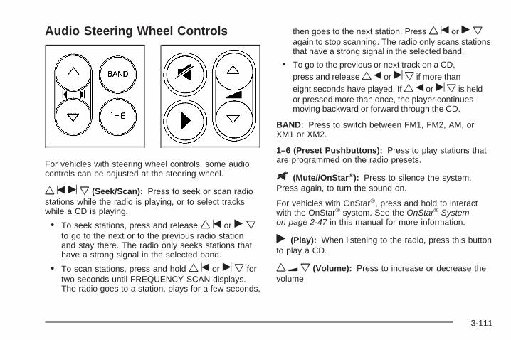
Audio Steering Wheel Controls
For vehicles with steering wheel controls, some audiocontrols can be adjusted at the steering wheel.
wt u x (Seek/Scan): Press to seek or scan radiostations while the radio is playing, or to select trackswhile a CD is playing.
• To seek stations, press and release w t or u xto go to the next or to the previous radio stationand stay there. The radio only seeks stations thathave a strong signal in the selected band.
• To scan stations, press and hold w t or u x fortwo seconds until FREQUENCY SCAN displays.The radio goes to a station, plays for a few seconds,
then goes to the next station. Press wt or uxagain to stop scanning. The radio only scans stationsthat have a strong signal in the selected band.
• To go to the previous or next track on a CD,press and release wt or ux if more thaneight seconds have played. If wt or ux is heldor pressed more than once, the player continuesmoving backward or forward through the CD.
BAND: Press to switch between FM1, FM2, AM, orXM1 or XM2.
1–6 (Preset Pushbuttons): Press to play stations thatare programmed on the radio presets.
$ (Mute//OnStar®): Press to silence the system.Press again, to turn the sound on.
For vehicles with OnStar®, press and hold to interactwith the OnStar® system. See the OnStar® Systemon page 2-47 in this manual for more information.
r (Play): When listening to the radio, press this buttonto play a CD.
wu x (Volume): Press to increase or decrease thevolume.
3-111
Radio ReceptionFrequency interference and static can occur duringnormal radio reception if items such as cell phonechargers, vehicle convenience accessories, and externalelectronic devices are plugged into the accessorypower outlet. If there is interference or static, unplug theitem from the accessory power outlet.
AMThe range for most AM stations is greater than for FM,especially at night. The longer range can cause stationfrequencies to interfere with each other. For better radioreception, most AM radio stations boost the power levelsduring the day, and then reduce these levels during thenight. Static can also occur when things like storms andpower lines interfere with radio reception. When thishappens, try reducing the treble on the radio.
FM StereoFM signals only reach about 10 to 40 miles(16 to 65 km). Although the radio has a built-in electroniccircuit that automatically works to reduce interference,some static can occur, especially around tall buildings orhills, causing the sound to fade in and out.
XM Satellite Radio ServiceXM Satellite Radio Service gives digital radio receptionfrom coast-to-coast in the 48 contiguous United States,and in Canada. Just as with FM, tall buildings or hills caninterfere with satellite radio signals, causing the sound tofade in and out. In addition, traveling or standing underheavy foliage, bridges, garages, or tunnels may causeloss of the XM signal for a period of time.
Cellular Phone UsageCellular phone usage may cause interference with thevehicle’s radio. This interference may occur whenmaking or receiving phone calls, charging the phone’sbattery, or simply having the phone on. This interferencecauses an increased level of static while listening tothe radio. If static is received while listening to the radio,unplug the cellular phone and turn it off.
3-112

Fixed Mast AntennaThe fixed mast antenna can withstand most car washeswithout being damaged as long as it is securelyattached to the base. If the mast becomes slightly bent,straighten it out by hand. If the mast is badly bent,replace it.
Occasionally check to make sure the antenna istightened to its base. If tightening is required, tightenby hand until fully seated plus one quarter turn.
XM™ Satellite Radio AntennaSystemThe XM Satellite Radio antenna is located on the roof ofthe vehicle. Keep the antenna clear of obstructions forclear radio reception.
Chime Level AdjustmentThe radio is used to adjust the vehicle’s chime volumelevel. To adjust the chime volume level:
1. Turn the radio off with the ignition in the ON/RUNposition.
2. Press and hold pushbutton 6, the volume level willchange from the normal level to loud, and LOUDwill appear on the radio display.
• If the chime volume is at the normal level, itchanges to the loud level and LOUD appears onthe radio display.
• If the chime volume is at the loud level, itchanges to the normal level and NORMALappears on the radio display.
Removing the radio and not replacing it with a factoryradio or chime module disables the chimes.
3-113

✍ NOTES
3-114
Your Driving, the Road, and the Vehicle ............4-2Defensive Driving ...........................................4-2Drunk Driving .................................................4-2Control of a Vehicle ........................................4-3Braking .........................................................4-4Antilock Brake System (ABS) ...........................4-5Braking in Emergencies ...................................4-6Traction Control System (TCS) .........................4-6StabiliTrak® System ........................................4-7Steering ........................................................4-9Off-Road Recovery .......................................4-11Passing .......................................................4-11Loss of Control .............................................4-11Driving at Night ............................................4-12
Driving in Rain and on Wet Roads ..................4-13Before Leaving on a Long Trip .......................4-14Highway Hypnosis ........................................4-14Hill and Mountain Roads ................................4-15Winter Driving ..............................................4-16If Your Vehicle is Stuck in Sand, Mud,
Ice, or Snow .............................................4-18Rocking Your Vehicle to Get It Out .................4-18Loading the Vehicle ......................................4-19
Towing ..........................................................4-24Towing Your Vehicle .....................................4-24Recreational Vehicle Towing ...........................4-24Level Control ...............................................4-25Towing a Trailer ...........................................4-26
Section 4 Driving Your Vehicle
4-1
Your Driving, the Road, andthe Vehicle
Defensive DrivingDefensive driving means “always expect theunexpected.” The first step in driving defensively is towear your safety belt — See Safety Belts: They Are forEveryone on page 1-23.
{CAUTION:
Assume that other road users (pedestrians,bicyclists, and other drivers) are going to becareless and make mistakes. Anticipate what theymight do and be ready. In addition:
• Allow enough following distance between youand the driver in front of you.
• Focus on the task of driving.
Driver distraction can cause collisions resulting ininjury or possible death. These simple defensivedriving techniques could save your life.
Drunk Driving
{CAUTION:
Drinking and then driving is very dangerous.Your reflexes, perceptions, attentiveness, andjudgment can be affected by even a small amountof alcohol. You can have a serious — or evenfatal — collision if you drive after drinking. Do notdrink and drive or ride with a driver who has beendrinking. Ride home in a cab; or if you are with agroup, designate a driver who will not drink.
Death and injury associated with drinking and driving isa global tragedy.
Alcohol affects four things that anyone needs to drive avehicle: judgment, muscular coordination, vision, andattentiveness.
4-2
Police records show that almost 40 percent of all motorvehicle-related deaths involve alcohol. In most cases,these deaths are the result of someone who was drinkingand driving. In recent years, more than 17,000 annualmotor vehicle-related deaths have been associated withthe use of alcohol, with about 250,000 people injured.
For persons under 21, it is against the law in everyU.S. state to drink alcohol. There are good medical,psychological, and developmental reasons forthese laws.
The obvious way to eliminate the leading highwaysafety problem is for people never to drink alcohol andthen drive.
Medical research shows that alcohol in a person’ssystem can make crash injuries worse, especiallyinjuries to the brain, spinal cord, or heart. This means
that when anyone who has been drinking — driver orpassenger — is in a crash, that person’s chanceof being killed or permanently disabled is higher than ifthe person had not been drinking.
Control of a VehicleThe following three systems help to control your vehiclewhile driving — brakes, steering, and accelerator.At times, as when driving on snow or ice, it is easy toask more of those control systems than the tiresand road can provide. Meaning, you can lose control ofyour vehicle. See Traction Control System (TCS) onpage 4-6 and StabiliTrak® System on page 4-7.
Adding non-dealer/non-retailer accessories can affectyour vehicle’s performance. See Accessories andModifications on page 5-3.
4-3
BrakingSee Brake System Warning Light on page 3-35.
Braking action involves perception time and reactiontime. First, you have to decide to push on the brakepedal. That is perception time. Then you have to bringup your foot and do it. That is reaction time.
Average reaction time is about three-fourths of asecond. But that is only an average. It might be lesswith one driver and as long as two or three seconds ormore with another. Age, physical condition, alertness,coordination, and eyesight all play a part. So do alcohol,drugs, and frustration. But even in three-fourths ofa second, a vehicle moving at 60 mph (100 km/h) travels66 feet (20 m). That could be a lot of distance in anemergency, so keeping enough space betweenyour vehicle and others is important.
And, of course, actual stopping distances vary greatlywith the surface of the road, whether it is pavement orgravel; the condition of the road, whether it is wet, dry, oricy; tire tread; the condition of the brakes; the weight ofthe vehicle; and the amount of brake force applied.
Avoid needless heavy braking. Some people drivein spurts — heavy acceleration followed by heavybraking — rather than keeping pace with traffic. This isa mistake. The brakes might not have time to coolbetween hard stops. The brakes will wear out muchfaster if you do a lot of heavy braking. If you keep pacewith the traffic and allow realistic following distances,you will eliminate a lot of unnecessary braking.That means better braking and longer brake life.
If your vehicle’s engine ever stops while you are driving,brake normally but do not pump the brakes. If you do,the pedal could get harder to push down. If theengine stops, you will still have some power brakeassist. But you will use it when you brake. Once thepower assist is used up, it can take longer to stop andthe brake pedal will be harder to push.
Adding non-dealer/non-retailer accessories can affectyour vehicle’s performance. See Accessories andModifications on page 5-3.
4-4
Antilock Brake System (ABS)Your vehicle has the Antilock Brake System (ABS), anadvanced electronic braking system that will helpprevent a braking skid.
When you start the engine and begin to drive away,ABS will check itself. You might hear a momentarymotor or clicking noise while this test is going on, andyou might even notice that the brake pedal movesor pulses a little. This is normal.
If there is a problem withABS, this warning light willstay on. See Antilock BrakeSystem (ABS) WarningLight on page 3-36.
Let us say the road is wet and you are driving safely.Suddenly, an animal jumps out in front of you. You slamon the brakes and continue braking. Here is whathappens with ABS:
A computer senses that the wheels are slowing down.If one of the wheels is about to stop rolling, the computerwill separately work the brakes at each wheel.
ABS can change the brake pressure to each wheel, asrequired, faster than any driver could. This can helpyou steer around the obstacle while braking hard.
As you brake, the computer keeps receiving updates onwheel speed and controls braking pressure accordingly.
Remember: ABS does not change the time you need toget your foot up to the brake pedal or always decreasestopping distance. If you get too close to the vehicle infront of you, you will not have time to apply the brakesif that vehicle suddenly slows or stops. Always leaveenough room up ahead to stop, even though youhave ABS.
4-5
Using ABSDo not pump the brakes. Just hold the brake pedaldown firmly and let antilock work for you. You might feela slight brake pedal pulsation or notice some noise,but this is normal.
Braking in EmergenciesWith ABS, you can steer and brake at the same time.In many emergencies, steering can help you more thaneven the very best braking.
Traction Control System (TCS)Your vehicle may have a traction control system thatlimits wheel spin. This is especially useful in slipperyroad conditions. The system operates if it senses thatone or both of the front wheels are spinning or beginningto lose traction. When this happens, the systembrakes the spinning wheel(s) and/or reduces enginepower to limit wheel spin.
The TRACTION CONTROL ACTIVE message will comeon in the Driver Information Center (DIC) when thetraction control system is limiting wheel spin. You mayfeel or hear the system working, but this is normal.
If your vehicle is in cruise control when the tractioncontrol system begins to limit wheel spin, the cruisecontrol will automatically disengage. When roadconditions allow you to safely use it again, you mayre-engage the cruise control.
This warning light will comeon to let you know if there isa problem with your tractioncontrol system.
When this warning light is on, the system will not limitwheel spin. Adjust your driving accordingly.
If the SERVICE TRACTION SYSTEM message in theDIC comes on and stays on or comes on while you aredriving, there’s a problem with your traction controlsystem. Have the traction control system serviced byyour dealer/retailer as soon as possible.
When this warning message is on, the TRACTIONCONTROL OFF message in the DIC will come on toremind you that the system will not limit wheel spin.Adjust your driving accordingly.
4-6
The traction control system automatically comes onwhenever you start your vehicle. To limit wheel spin,especially in slippery road conditions, you should alwaysleave the system on. But you can turn the traction controlsystem off if you ever need to. You should turn thesystem off if your vehicle ever gets stuck in sand, mud orsnow and rocking the vehicle is required. See RockingYour Vehicle to Get It Out on page 4-18 and If YourVehicle is Stuck in Sand, Mud, Ice, or Snow onpage 4-18.
To turn the system off,press the traction controlbutton located on thecenter of the instrumentpanel.
If the system is limiting wheel spin when you press thebutton, the TRACTION CONTROL ACTIVE message willgo off, but the system will not turn off until there is nolonger a current need to limit wheel spin. The TRACTIONCONTROL OFF message will come on to remind you thesystem is off. You can turn the system back on at anytime by pressing the button again. The traction controlsystem warning message should go off.
Adding non-dealer/non-retailer accessories can affectyour vehicle’s performance. See Accessories andModifications on page 5-3 for more information.
StabiliTrak® SystemYour vehicle may be equipped with StabiliTrak whichcombines anti-lock brake, traction and stability controlsystems and helps the driver maintain directional controlof the vehicle in most driving conditions.
When you first start your vehicle and begin to driveaway, the system performs several diagnostic checks toinsure there are no problems. You may hear or feelthe system working. This is normal and does not meanthere is a problem with your vehicle.
If the system fails to turn on or activate, the SERVICESTABILITY SYSTEM message will be displayed onthe Driver Information Center (DIC). If the vehicle hasgone through heavy acceleration or braking or multipleturns during the first two miles of driving after startingyour vehicle, the STABILITY CONTROL OFF messagemay appear on the DIC. If this is the case, yourvehicle does not need servicing. You will need to turnthe vehicle off and then restart it to initialize StabiliTrak.If either message appears on the DIC, and yourvehicle has not gone through hard acceleration, brakingor multiple turns in the first two miles of driving, yourvehicle should be taken in for service.
4-7
The STABILITY CONTROL ACTIVE message willappear on the DIC only when the system is both on andactivated. It means that an advanced computer-controlledsystem has come on to help your vehicle continue to goin the direction in which you are steering. StabiliTrakactivates when the computer senses that your vehicleis just starting to spin, as it might if you hit a patch of iceor other slippery spot on the road. When the systemactivates, you may hear a noise or feel a vibration in thebrake pedal. This is normal. When the STABILITYCONTROL ACTIVE message is on, you should continueto steer in the direction you want to go. The system isdesigned to help you in bad weather or other difficultdriving situations by making the most of whatever roadconditions will permit. For more information on thestability messages, see Driver Information Center (DIC)on page 3-43.
If the StabiliTrak system turns off, the traction controlsystem warning light will illuminate, and the STABILITYCONTROL OFF message will appear on the DIC towarn the driver that StabiliTrak is no longer availableto assist you with directional control of the vehicle.Adjust your driving accordingly.
To realize the full benefits of the stability enhancementsystem, you should normally leave StabiliTrak on, but itmay be necessary to turn the system off if your vehicle isstuck in sand, mud, ice or snow, and you want to “rock”your vehicle to attempt to free it. See Rocking YourVehicle to Get It Out on page 4-18 and If Your Vehicle isStuck in Sand, Mud, Ice, or Snow on page 4-18.
Traction Control OperationThe traction control system is part of the StabiliTraksystem. Traction control limits wheel spin by reducingengine power to the wheels (engine speed management)and by applying brakes.
The traction control system is enabled automaticallywhen you start your vehicle. It will activate and displaythe TRACTION CONTROL ACTIVE message in theDIC if it senses that one or both of the front wheels arespinning or beginning to lose traction while driving.
4-8
If the brake traction-control system activates constantlyor if the brakes have heated up due to high-speedbraking, brake traction-control will be disabled and theTRACTION CONTROL ACTIVE message will bedisplayed. In the limited mode, the traction controlsystem will only use engine traction-control and is limitedin its ability to provide optimal performance since thesystem will not utilize brake traction-control to controlslip on the drive wheels. The system will return to normaloperation after the brakes have cooled. This can takeup to two minutes or longer depending on brake usage.
The traction control system may activate on dry orrough roads or under conditions such as heavyacceleration while turning or abrupt upshifts/downshiftsof the transaxle. When this happens you may noticea reduction in acceleration, or may hear a noiseor vibration. This is normal.
If your vehicle is in cruise control when the systemactivates, the STABILITY CONTROL ACTIVE messagewill appear on the DIC and the cruise control willautomatically disengage. When road conditions allowyou to use cruise again, you may re-engage the cruisecontrol. See Cruise Control on page 3-10.
StabiliTrak may also turn off automatically if itdetermines that a problem exists with the system. If theproblem does not clear itself after restarting the vehicle,you should see your dealer/retailer for service.
Steering
Power SteeringIf you lose power steering assist because the enginestops or the system is not functioning, you can steer butit will take much more effort.
Steering TipsIt is important to take curves at a reasonable speed.
Traction in a curve depends on the condition of the tiresand the road surface, the angle at which the curve isbanked, and your speed. While in a curve, speed is theone factor you can control.
If you need to reduce speed, do it before you enter thecurve, while the front wheels are straight ahead.
Try to adjust the speed so you can drive through thecurve. Maintain a reasonable, steady speed. Waitto accelerate until you are out of the curve, and thenaccelerate gently into the straightaway.
4-9
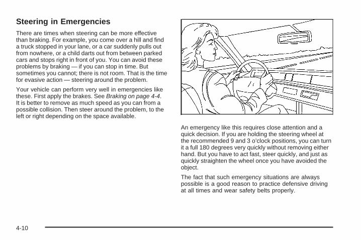
Steering in EmergenciesThere are times when steering can be more effectivethan braking. For example, you come over a hill and finda truck stopped in your lane, or a car suddenly pulls outfrom nowhere, or a child darts out from between parkedcars and stops right in front of you. You can avoid theseproblems by braking — if you can stop in time. Butsometimes you cannot; there is not room. That is the timefor evasive action — steering around the problem.
Your vehicle can perform very well in emergencies likethese. First apply the brakes. See Braking on page 4-4.It is better to remove as much speed as you can from apossible collision. Then steer around the problem, to theleft or right depending on the space available.
An emergency like this requires close attention and aquick decision. If you are holding the steering wheel atthe recommended 9 and 3 o’clock positions, you can turnit a full 180 degrees very quickly without removing eitherhand. But you have to act fast, steer quickly, and just asquickly straighten the wheel once you have avoided theobject.
The fact that such emergency situations are alwayspossible is a good reason to practice defensive drivingat all times and wear safety belts properly.
4-10
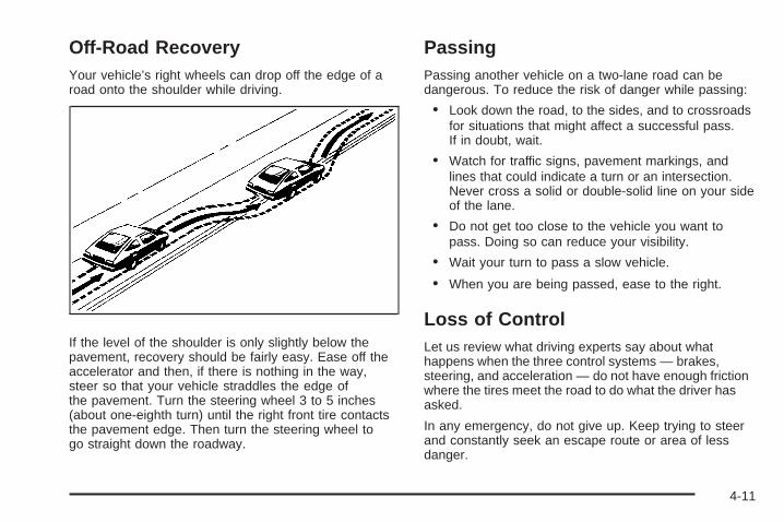
Off-Road RecoveryYour vehicle’s right wheels can drop off the edge of aroad onto the shoulder while driving.
If the level of the shoulder is only slightly below thepavement, recovery should be fairly easy. Ease off theaccelerator and then, if there is nothing in the way,steer so that your vehicle straddles the edge ofthe pavement. Turn the steering wheel 3 to 5 inches(about one-eighth turn) until the right front tire contactsthe pavement edge. Then turn the steering wheel togo straight down the roadway.
PassingPassing another vehicle on a two-lane road can bedangerous. To reduce the risk of danger while passing:
• Look down the road, to the sides, and to crossroadsfor situations that might affect a successful pass.If in doubt, wait.
• Watch for traffic signs, pavement markings, andlines that could indicate a turn or an intersection.Never cross a solid or double-solid line on your sideof the lane.
• Do not get too close to the vehicle you want topass. Doing so can reduce your visibility.
• Wait your turn to pass a slow vehicle.
• When you are being passed, ease to the right.
Loss of ControlLet us review what driving experts say about whathappens when the three control systems — brakes,steering, and acceleration — do not have enough frictionwhere the tires meet the road to do what the driver hasasked.
In any emergency, do not give up. Keep trying to steerand constantly seek an escape route or area of lessdanger.
4-11
SkiddingIn a skid, a driver can lose control of the vehicle.Defensive drivers avoid most skids by taking reasonablecare suited to existing conditions, and by not overdrivingthose conditions. But skids are always possible.
The three types of skids correspond to your vehicle’sthree control systems. In the braking skid, the wheels arenot rolling. In the steering or cornering skid, too muchspeed or steering in a curve causes tires to slip and losecornering force. And in the acceleration skid, too muchthrottle causes the driving wheels to spin.
Remember: Any traction control system helps avoid onlythe acceleration skid. If your traction control system isoff, then an acceleration skid is best handled byeasing your foot off the accelerator pedal.
If your vehicle starts to slide, ease your foot off theaccelerator pedal and quickly steer the way you wantthe vehicle to go. If you start steering quickly enough,your vehicle may straighten out. Always be readyfor a second skid if it occurs.
Of course, traction is reduced when water, snow, ice,gravel, or other material is on the road. For safety,you will want to slow down and adjust your driving tothese conditions. It is important to slow down on slipperysurfaces because stopping distance will be longer andvehicle control more limited.
While driving on a surface with reduced traction, tryyour best to avoid sudden steering, acceleration, orbraking, including reducing vehicle speed by shifting to alower gear. Any sudden changes could cause the tires toslide. You may not realize the surface is slippery untilyour vehicle is skidding. Learn to recognize warningclues — such as enough water, ice, or packed snow onthe road to make a mirrored surface — and slow downwhen you have any doubt.
Remember: Any Antilock Brake System (ABS) helpsavoid only the braking skid.
Driving at NightNight driving is more dangerous than day drivingbecause some drivers are likely to be impaired — byalcohol or drugs, with night vision problems, or by fatigue.
Night driving tips include:
• Drive defensively.
• Do not drink and drive.
• Reduce headlamp glare by adjusting the insiderearview mirror.
• Slow down and keep more space between you andother vehicles because headlamps can only light upso much road ahead.
4-12
• Watch for animals.
• When tired, pull off the road.
• Do not wear sunglasses.
• Avoid staring directly into approaching headlamps.
• Keep the windshield and all glass on your vehicleclean — inside and out.
• Keep your eyes moving, especially during turns orcurves.
No one can see as well at night as in the daytime.But, as we get older, these differences increase.A 50-year-old driver might need at least twice as muchlight to see the same thing at night as a 20-year-old.
Driving in Rain and on Wet RoadsRain and wet roads can reduce vehicle tractionand affect your ability to stop and accelerate. Alwaysdrive slower in these types of driving conditionsand avoid driving through large puddles anddeep-standing or flowing water.
{CAUTION:
Wet brakes can cause crashes. They might notwork as well in a quick stop and could cause pullingto one side. You could lose control of the vehicle.
After driving through a large puddle of water or acar/vehicle wash, lightly apply the brake pedal untilthe brakes work normally.
Flowing or rushing water creates strong forces.Driving through flowing water could cause yourvehicle to be carried away. If this happens, you andother vehicle occupants could drown. Do not ignorepolice warnings and be very cautious about trying todrive through flowing water.
HydroplaningHydroplaning is dangerous. Water can build up underyour vehicle’s tires so they actually ride on the water. Thiscan happen if the road is wet enough and you are goingfast enough. When your vehicle is hydroplaning, it haslittle or no contact with the road.
There is no hard and fast rule about hydroplaning.The best advice is to slow down when the road is wet.
4-13
Other Rainy Weather TipsBesides slowing down, other wet weather driving tipsinclude:
• Allow extra following distance.
• Pass with caution.
• Keep windshield wiping equipment in good shape.
• Keep the windshield washer fluid reservoir filled.
• Have good tires with proper tread depth. See Tireson page 5-47.
• Turn off cruise control, if equipped.
Before Leaving on a Long TripTo prepare your vehicle for a long trip, consider havingit serviced by your dealer/retailer before departing.
Things to check on your own include:
• Windshield Washer Fluid: Reservoir full? Windowsclean — inside and outside?
• Wiper Blades: In good shape?
• Fuel, Engine Oil, Other Fluids: All levels checked?
• Lamps: Do they all work and are lenses clean?
• Tires: Are treads good? Are tires inflated torecommended pressure?
• Weather and Maps: Safe to travel? Haveup-to-date maps?
Highway HypnosisAlways be alert and pay attention to your surroundingswhile driving. If you become tired or sleepy, find asafe place to park your vehicle and rest.
Other driving tips include:
• Keep the vehicle well ventilated.
• Keep interior temperature cool.
• Keep your eyes moving — scan the road aheadand to the sides.
• Check the rearview mirror and vehicle instrumentsoften.
4-14
Hill and Mountain RoadsDriving on steep hills or through mountains is differentthan driving on flat or rolling terrain. Tips for drivingin these conditions include:
• Keep the vehicle serviced and in good shape.
• Check all fluid levels and brakes, tires, coolingsystem, and transmission.
• Going down steep or long hills, shift to alower gear.
{CAUTION:
If you do not shift down, the brakes could get sohot that they would not work well. You would thenhave poor braking or even none going down a hill.You could crash. Shift down to let the engineassist the brakes on a steep downhill slope.
{CAUTION:
Coasting downhill in N (Neutral) or with the ignitionoff is dangerous. The brakes will have to do all thework of slowing down and they could get so hotthat they would not work well. You would thenhave poor braking or even none going down a hill.You could crash. Always have the engine runningand the vehicle in gear when going downhill.
• Stay in your own lane. Do not swing wide or cutacross the center of the road. Drive at speedsthat let you stay in your own lane.
• Top of hills: Be alert — something could be in yourlane (stalled car, accident).
• Pay attention to special road signs (falling rocksarea, winding roads, long grades, passing orno-passing zones) and take appropriate action.
4-15

Winter Driving
Driving on Snow or IceDrive carefully when there is snow or ice between thetires and the road, creating less traction or grip. Wet icecan occur at about 32°F (0°C) when freezing rain beginsto fall, resulting in even less traction. Avoid driving on wetice or in freezing rain until roads can be treated with saltor sand.
Drive with caution, whatever the condition. Accelerategently so traction is not lost. Accelerating too quicklycauses the wheels to spin and makes the surface underthe tires slick, so there is even less traction.
Try not to break the fragile traction. If you accelerate toofast, the drive wheels will spin and polish the surfaceunder the tires even more.
The Traction Control System (TCS) on page 4-6improves the ability to accelerate on slippery roads, butslow down and adjust your driving to the road conditions.When driving through deep snow, turn off the tractioncontrol system to help maintain vehicle motion at lowerspeeds.
The Antilock Brake System (ABS) on page 4-5 improvesvehicle stability during hard stops on a slippery roads, butapply the brakes sooner than when on dry pavement.
Allow greater following distance on any slippery roadand watch for slippery spots. Icy patches can occur onotherwise clear roads in shaded areas. The surfaceof a curve or an overpass can remain icy whenthe surrounding roads are clear. Avoid suddensteering maneuvers and braking while on ice.
Turn off cruise control, if equipped, on slippery surfaces.
Blizzard ConditionsBeing stuck in snow can be in a serious situation. Staywith the vehicle unless there is help nearby. If possible,use the Roadside Assistance Program on page 7-7.To get help and keep everyone in the vehicle safe:
• Turn on the Hazard Warning Flashers on page 3-6.
• Tie a red cloth to an outside mirror.
4-16
{CAUTION:
Snow can trap engine exhaust under the vehicle.This may cause exhaust gases to get inside. Engineexhaust contains carbon monoxide (CO) whichcannot be seen or smelled. It can causeunconsciousness and even death.
If the vehicle is stuck in the snow:• Clear away snow from around the base of your
vehicle, especially any that is blocking theexhaust pipe.
• Check again from time to time to be sure snowdoes not collect there.
• Open a window about two inches on the side ofthe vehicle that is away from the wind to bringin fresh air.
• Fully open the air outlets on or under theinstrument panel.
• Adjust the Climate Control system to a settingthat circulates the air inside the vehicle andset the fan speed to the highest setting.See Climate Control System in the Index.
CAUTION: (Continued)
CAUTION: (Continued)
For more information about carbon monoxide, seeEngine Exhaust on page 2-41.
Snow can trap exhaust gases under your vehicle.This can cause deadly CO (carbon monoxide) gasto get inside. CO could overcome you and kill you.You cannot see it or smell it, so you might notknow it is in your vehicle. Clear away snow fromaround the base of your vehicle, especially anythat is blocking the exhaust
Run the engine for short periods only as needed tokeep warm, but be careful.To save fuel, run the engine for only short periods asneeded to warm the vehicle and then shut the engine offand close the window most of the way to save heat.Repeat this until help arrives but only when you feel reallyuncomfortable from the cold. Moving about to keep warmalso helps.If it takes some time for help to arrive, now and thenwhen you run the engine, push the accelerator pedalslightly so the engine runs faster than the idle speed.This keeps the battery charged to restart the vehicle andto signal for help with the headlamps. Do this as little aspossible to save fuel.
4-17
If Your Vehicle is Stuck in Sand,Mud, Ice, or SnowSlowly and cautiously spin the wheels to free thevehicle when stuck in sand, mud, ice, or snow. SeeRocking Your Vehicle to Get It Out on page 4-18.
If the vehicle has a traction system, it can often help tofree a stuck vehicle. Refer to the vehicle’s tractionsystem in the Index. If stuck too severely for the tractionsystem to free the vehicle, turn the traction system offand use the rocking method.
{CAUTION:
If you let your vehicle’s tires spin at high speed,they can explode, and you or others could beinjured. The vehicle can overheat, causing anengine compartment fire or other damage. Spinthe wheels as little as possible and avoid goingabove 35 mph (55 km/h) as shown on thespeedometer.
For information about using tire chains on the vehicle,see Tire Chains on page 5-70.
Rocking Your Vehicle to Get It OutTurn the steering wheel left and right to clear thearea around the front wheels. Turn off any tractionor stability system. Shift back and forth betweenR (Reverse) and a forward gear, spinning the wheels aslittle as possible. To prevent transmission wear, waituntil the wheels stop spinning before shifting gears.Release the accelerator pedal while shifting, and presslightly on the accelerator pedal when the transmissionis in gear. Slowly spinning the wheels in the forward andreverse directions causes a rocking motion that couldfree the vehicle. If that does not get the vehicle out aftera few tries, it might need to be towed out. If thevehicle does need to be towed out, see Towing YourVehicle on page 4-24.
4-18

Loading the VehicleIt is very important to know how much weight yourvehicle can carry. This weight is called the vehiclecapacity weight and includes the weight of alloccupants, cargo, and all nonfactory-installedoptions. Two labels on your vehicle show how muchweight it may properly carry, the Tire and LoadingInformation label and the Certification/Tire label.
{CAUTION:
Do not load the vehicle any heavier than theGross Vehicle Weight Rating (GVWR), oreither the maximum front or rear Gross AxleWeight Rating (GAWR). If you do, parts on thevehicle can break, and it can change the wayyour vehicle handles. These could cause youto lose control and crash. Also, overloadingcan shorten the life of the vehicle.
Tire and Loading Information Label
A vehicle specific Tire and Loading Informationlabel is attached to the center pillar (B-pillar) of yourvehicle. With the driver’s door open, you will find thelabel attached below the door lock post (striker).The tire and loading information label shows thenumber of occupant seating positions (A), and themaximum vehicle capacity weight (B) in kilogramsand pounds.
The Tire and Loading Information label also showsthe size of the original equipment tires (C) andthe recommended cold tire inflation pressures (D).
Example Label
4-19
For more information on tires and inflation seeTires on page 5-47 and Inflation - Tire Pressure onpage 5-54.
There is also important loading information on thevehicle Certification/Tire label. It tells you theGross Vehicle Weight Rating (GVWR) andthe Gross Axle Weight Rating (GAWR) for thefront and rear axle. See “Certification/Tire Label”later in this section.
Steps for Determining Correct Load Limit1. Locate the statement “The combined weight
of occupants and cargo should never exceedXXX kg or XXX lbs” on your vehicle’s placard.
2. Determine the combined weight of the driverand passengers that will be riding in yourvehicle.
3. Subtract the combined weight of the driverand passengers from XXX kg or XXX lbs.
4. The resulting figure equals the availableamount of cargo and luggage load capacity.For example, if the “XXX” amount equals1400 lbs and there will be five 150 lbpassengers in your vehicle, the amount ofavailable cargo and luggage load capacity is650 lbs (1400 − 750 (5 x 150) = 650 lbs).
5. Determine the combined weight of luggageand cargo being loaded on the vehicle. Thatweight may not safely exceed the availablecargo and luggage load capacity calculatedin Step 4.
6. If your vehicle will be towing a trailer, the loadfrom your trailer will be transferred to yourvehicle. Consult this manual to determine howthis reduces the available cargo and luggageload capacity for your vehicle.
See Towing a Trailer on page 4-26 for importantinformation on towing a trailer, towing safety rules,and trailering tips.
4-20
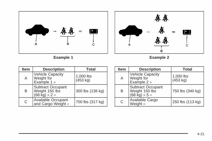
Item Description Total
AVehicle CapacityWeight forExample 1 =
1,000 lbs(453 kg)
BSubtract OccupantWeight 150 lbs(68 kg) × 2 =
300 lbs (136 kg)
C Available Occupantand Cargo Weight = 700 lbs (317 kg)
Item Description Total
AVehicle CapacityWeight forExample 2 =
1,000 lbs(453 kg)
BSubtract OccupantWeight 150 lbs(68 kg) × 5 =
750 lbs (340 kg)
C Available CargoWeight = 250 lbs (113 kg)
Example 1 Example 2
4-21
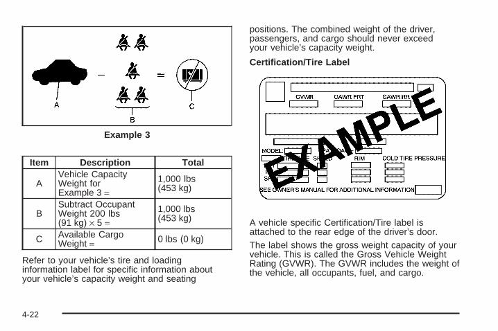
Item Description Total
AVehicle CapacityWeight forExample 3 =
1,000 lbs(453 kg)
BSubtract OccupantWeight 200 lbs(91 kg) × 5 =
1,000 lbs(453 kg)
C Available CargoWeight = 0 lbs (0 kg)
Refer to your vehicle’s tire and loadinginformation label for specific information aboutyour vehicle’s capacity weight and seating
positions. The combined weight of the driver,passengers, and cargo should never exceedyour vehicle’s capacity weight.
Certification/Tire Label
A vehicle specific Certification/Tire label isattached to the rear edge of the driver’s door.
The label shows the gross weight capacity of yourvehicle. This is called the Gross Vehicle WeightRating (GVWR). The GVWR includes the weight ofthe vehicle, all occupants, fuel, and cargo.
Example 3
4-22
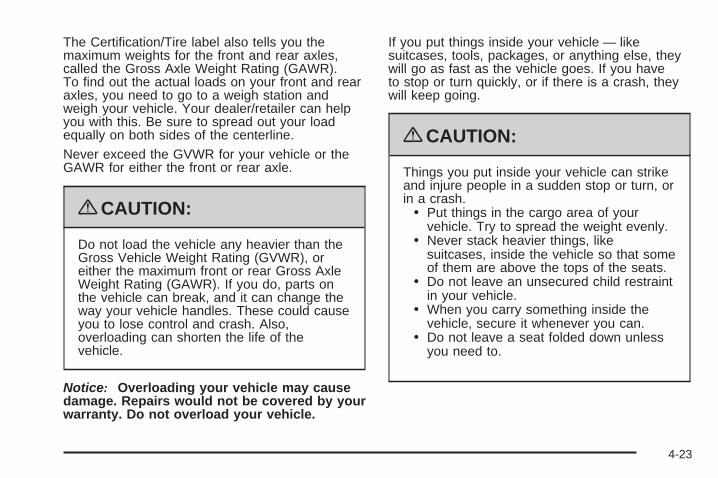
The Certification/Tire label also tells you themaximum weights for the front and rear axles,called the Gross Axle Weight Rating (GAWR).To find out the actual loads on your front and rearaxles, you need to go to a weigh station andweigh your vehicle. Your dealer/retailer can helpyou with this. Be sure to spread out your loadequally on both sides of the centerline.
Never exceed the GVWR for your vehicle or theGAWR for either the front or rear axle.
{CAUTION:
Do not load the vehicle any heavier than theGross Vehicle Weight Rating (GVWR), oreither the maximum front or rear Gross AxleWeight Rating (GAWR). If you do, parts onthe vehicle can break, and it can change theway your vehicle handles. These could causeyou to lose control and crash. Also,overloading can shorten the life of thevehicle.
Notice: Overloading your vehicle may causedamage. Repairs would not be covered by yourwarranty. Do not overload your vehicle.
If you put things inside your vehicle — likesuitcases, tools, packages, or anything else, theywill go as fast as the vehicle goes. If you haveto stop or turn quickly, or if there is a crash, theywill keep going.
{CAUTION:
Things you put inside your vehicle can strikeand injure people in a sudden stop or turn, orin a crash.
• Put things in the cargo area of yourvehicle. Try to spread the weight evenly.
• Never stack heavier things, likesuitcases, inside the vehicle so that someof them are above the tops of the seats.
• Do not leave an unsecured child restraintin your vehicle.
• When you carry something inside thevehicle, secure it whenever you can.
• Do not leave a seat folded down unlessyou need to.
4-23
Towing
Towing Your VehicleTo avoid vehicle damage, a platform or flatbed trailershould be used to transport this vehicle. Consultyour dealer/retailer or a professional towing serviceif you need to have your disabled vehicle towed.See Roadside Assistance Program on page 7-7.
If you want to tow your vehicle behind another vehiclefor recreational purposes (such as behind a motorhome),see “Recreational Vehicle Towing” following.
Recreational Vehicle TowingRecreational vehicle towing means towing your vehiclebehind another vehicle – such as behind a motorhome.The two most common types of recreational vehicletowing are known as “dinghy towing” (towing your vehiclewith all four wheels on the ground) and “dolly towing”(towing your vehicle with two wheels on the ground andtwo wheels up on a device know as a “dolly”).
With the proper preparation and equipment, manyvehicles can be towed in these ways. See “DinghyTowing” and “Dolly Towing,” following.
Here are some important things to consider before youdo recreational vehicle towing:
• What’s the towing capacity of the towing vehicle?Be sure you read the tow vehicle manufacturer’srecommendations.
• How far will you tow? Some vehicles haverestrictions on how far and how long they can tow.
• Do you have the proper towing equipment?See your dealer/retailer or trailering professional foradditional advice and equipment recommendations.
• Is your vehicle ready to be towed? Just as youwould prepare your vehicle for a long trip, you’llwant to make sure your vehicle is prepared to betowed. See Before Leaving on a Long Trip onpage 4-14.
4-24
Dinghy TowingYour vehicle was not designed to be towed with all of itswheels on the ground. It can be towed with the tworear wheels on the ground. See “Dolly Towing” followingfor more information.
Dolly TowingTo dolly tow your vehicle, do the following:
1. Put the front wheels on a dolly.
2. Put the vehicle in PARK (P).
3. Set the parking brake.
4. Clamp the steering wheel in a straight-aheadposition with a clamping device designed for towing.
5. Remove the key from the ignition.
6. Secure the vehicle to the dolly.
7. Release the parking brake.
Level ControlOn vehicles equipped with automatic level control, therear of the vehicle is automatically kept level as you loador unload your vehicle. However, you should still notexceed the GVWR or the GAWR. See Loading theVehicle on page 4-19.
You may hear the compressor operating when you loador unload your vehicle, and periodically as the systemself-adjusts. This is normal. The compressor shouldoperate for brief periods of time. If the sound continuesfor an extended period of time, your vehicle needsservice.
Using heavier suspension components to get addeddurability might not change your weight ratings. Ask yourdealer to help you load your vehicle the right way.
4-25
Towing a Trailer
{CAUTION:
The driver can lose control when pulling a trailer ifthe correct equipment is not used or the vehicle isnot driven properly. For example, if the trailer istoo heavy, the brakes may not work well — oreven at all. The driver and passengers could beseriously injured. The vehicle may also bedamaged; the resulting repairs would not becovered by the vehicle warranty. Pull a trailer onlyif all the steps in this section have been followed.Ask your dealer/retailer for advice and informationabout towing a trailer with the vehicle.
Notice: Pulling a trailer improperly can damage thevehicle and result in costly repairs not coveredby the vehicle warranty. To pull a trailer correctly,follow the advice in this section and see yourdealer/retailer for important information abouttowing a trailer with the vehicle.
Your vehicle can tow a trailer. To identify the traileringcapacity of vehicle, you should read the informationin “Weight of the Trailer” that appears later in thissection. Trailering is different than just driving yourvehicle by itself. Trailering means changes in handling,acceleration, braking, durability, and fuel economy.Successful, safe trailering takes correct equipment, andit has to be used properly.
That is the reason for this section. In it are manytime-tested, important trailering tips and safety rules.Many of these are important for your safety and that ofyour passengers. So please read this section carefullybefore you pull a trailer.
Load-pulling components such as the engine,transmission, wheel assemblies, and tires are forced towork harder against the drag of the added weight.The engine is required to operate at relatively higherspeeds and under greater loads, generating extra heat.The trailer also adds considerably to wind resistance,increasing the pulling requirements.
4-26
If You Do Decide To Pull A TrailerIf you do, here are some important points:
• There are many different laws, including speed limitrestrictions, having to do with trailering. Make sureyour rig will be legal, not only where you livebut also where you’ll be driving. A good source forthis information can be state or provincial police.
• Consider using a sway control. See “Hitches” laterin this section.
• Do not tow a trailer at all during the first 500 miles(800 km) your new vehicle is driven. Your engine,axle, or other parts could be damaged.
• During the first 500 miles (800 km) that you tow atrailer, do not drive over 50 mph (80 km/h) and donot make starts at full throttle. This helps yourengine and other parts of your vehicle wear in atthe heavier loads.
• You can use THIRD (3) or, as you need to, a lowergear when towing a trailer. Operating your vehiclein THIRD (3) when towing a trailer will minimize heatbuildup and extend the life of your transmission.
Three important considerations have to do with weight:
• Weight of the trailer
• Weight of the trailer tongue
• Weight on your vehicle’s tires
4-27
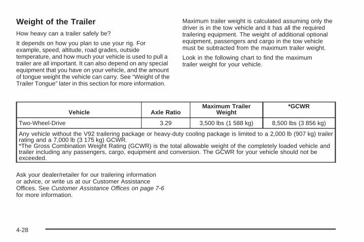
Weight of the TrailerHow heavy can a trailer safely be?
It depends on how you plan to use your rig. Forexample, speed, altitude, road grades, outsidetemperature, and how much your vehicle is used to pull atrailer are all important. It can also depend on any specialequipment that you have on your vehicle, and the amountof tongue weight the vehicle can carry. See “Weight of theTrailer Tongue” later in this section for more information.
Maximum trailer weight is calculated assuming only thedriver is in the tow vehicle and it has all the requiredtrailering equipment. The weight of additional optionalequipment, passengers and cargo in the tow vehiclemust be subtracted from the maximum trailer weight.
Look in the following chart to find the maximumtrailer weight for your vehicle.
Vehicle Axle RatioMaximum Trailer
Weight*GCWR
Two-Wheel-Drive 3.29 3,500 lbs (1 588 kg) 8,500 lbs (3 856 kg)
Any vehicle without the V92 trailering package or heavy-duty cooling package is limited to a 2,000 lb (907 kg) trailerrating and a 7,000 lb (3 175 kg) GCWR.*The Gross Combination Weight Rating (GCWR) is the total allowable weight of the completely loaded vehicle andtrailer including any passengers, cargo, equipment and conversion. The GCWR for your vehicle should not beexceeded.
Ask your dealer/retailer for our trailering informationor advice, or write us at our Customer AssistanceOffices. See Customer Assistance Offices on page 7-6for more information.
4-28
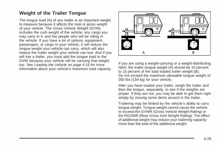
Weight of the Trailer TongueThe tongue load (A) of any trailer is an important weightto measure because it affects the total or gross weightof your vehicle. The Gross Vehicle Weight (GVW)includes the curb weight of the vehicle, any cargo youmay carry in it, and the people who will be riding inthe vehicle. If you have a lot of options, equipment,passengers, or cargo in your vehicle, it will reduce thetongue weight your vehicle can carry, which will alsoreduce the trailer weight your vehicle can tow. And if youwill tow a trailer, you must add the tongue load to theGVW because your vehicle will be carrying that weight,too. See Loading the Vehicle on page 4-19 for moreinformation about your vehicle’s maximum load capacity.
If you are using a weight-carrying or a weight-distributinghitch, the trailer tongue weight (A) should be 10 percentto 15 percent of the total loaded trailer weight (B).Do not exceed the maximum allowable tongue weight of350 lbs (159 kg) for your vehicle.
After you have loaded your trailer, weigh the trailer andthen the tongue, separately, to see if the weights areproper. If they are not, you may be able to get them rightsimply by moving some items around in the trailer.
Trailering may be limited by the vehicle’s ability to carrytongue weight. Tongue weight cannot cause the vehicleto exceed the GVWR (Gross Vehicle Weight Rating) orthe RGAWR (Rear Gross Axle Weight Rating). The effectof additional weight may reduce your trailering capacitymore than the total of the additional weight.
4-29
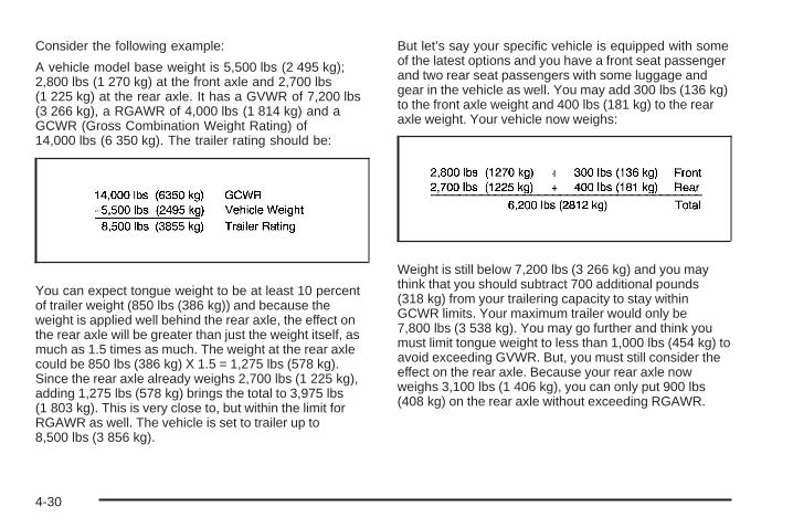
Consider the following example:
A vehicle model base weight is 5,500 lbs (2 495 kg);2,800 lbs (1 270 kg) at the front axle and 2,700 lbs(1 225 kg) at the rear axle. It has a GVWR of 7,200 lbs(3 266 kg), a RGAWR of 4,000 lbs (1 814 kg) and aGCWR (Gross Combination Weight Rating) of14,000 lbs (6 350 kg). The trailer rating should be:
You can expect tongue weight to be at least 10 percentof trailer weight (850 lbs (386 kg)) and because theweight is applied well behind the rear axle, the effect onthe rear axle will be greater than just the weight itself, asmuch as 1.5 times as much. The weight at the rear axlecould be 850 lbs (386 kg) X 1.5 = 1,275 lbs (578 kg).Since the rear axle already weighs 2,700 lbs (1 225 kg),adding 1,275 lbs (578 kg) brings the total to 3,975 lbs(1 803 kg). This is very close to, but within the limit forRGAWR as well. The vehicle is set to trailer up to8,500 lbs (3 856 kg).
But let’s say your specific vehicle is equipped with someof the latest options and you have a front seat passengerand two rear seat passengers with some luggage andgear in the vehicle as well. You may add 300 lbs (136 kg)to the front axle weight and 400 lbs (181 kg) to the rearaxle weight. Your vehicle now weighs:
Weight is still below 7,200 lbs (3 266 kg) and you maythink that you should subtract 700 additional pounds(318 kg) from your trailering capacity to stay withinGCWR limits. Your maximum trailer would only be7,800 lbs (3 538 kg). You may go further and think youmust limit tongue weight to less than 1,000 lbs (454 kg) toavoid exceeding GVWR. But, you must still consider theeffect on the rear axle. Because your rear axle nowweighs 3,100 lbs (1 406 kg), you can only put 900 lbs(408 kg) on the rear axle without exceeding RGAWR.
4-30
The effect of tongue weight is about 1.5 times the actualweight. Dividing the 900 lbs (408 kg) by 1.5 leaves youwith being able to handle only 600 lbs (272 kg) of tongueweight. Since tongue weight is usually at least 10 percentof total loaded trailer weight, you can expect that thelargest trailer your vehicle can properly handle is6,000 lbs (2 721 kg).
It is important that you make sure your vehicle does notexceed any of its ratings — GCWR, GVWR, RGAWR,Maximum Trailer Rating or Tongue Weight. Theonly way to be sure you are not exceeding any ofthese ratings is to weigh your vehicle and trailer.
Total Weight on Your Vehicle’s TiresBe sure your vehicle’s tires are inflated to the upperlimit for cold tires. You will find these numbers onthe Certification/Tire label at the rear edge of the driver’sdoor or see Loading the Vehicle on page 4-19. Thenbe sure you do not go over the GVW limit for yourvehicle, including the weight of the trailer tongue.
HitchesIt is important to have the correct hitch equipment.Crosswinds, large trucks going by, and rough roads area few reasons why you will need the right hitch. Hereare some rules to follow:
• The bumpers on your vehicle are not intendedfor hitches. Do not attach rental hitches or otherbumper-type hitches to them. Use only aframe-mounted hitch that does not attach tothe bumper.
• Will you have to make any holes in the body of yourvehicle when you install a trailer hitch?
If you do, remember to seal the holes later when youremove the hitch. If you do not seal them, deadlycarbon monoxide (CO) from your exhaust can getinto your vehicle. See Engine Exhaust on page 2-41.Dirt and water can, too.
4-31
Safety ChainsYou should always attach chains between your vehicleand your trailer. Cross the safety chains under the tongueof the trailer to help prevent the tongue from contactingthe road if it becomes separated from the hitch.Instructions about safety chains may be provided by thehitch manufacturer or by the trailer manufacturer. Followthe manufacturer’s recommendation for attaching safetychains and do not attach them to the bumper. Alwaysleave just enough slack so you can turn with your rig.Never allow safety chains to drag on the ground.
Trailer BrakesIf your trailer weighs more than 1,000 lbs (450 kg)loaded, then it needs its own brakes – and they must beadequate. Be sure to read and follow the instructionsfor the trailer brakes so you will be able to install, adjust,and maintain them properly.
Because your vehicle may have anti-lock brakes, do nottry to tap into your vehicle’s brake system. If you do,both brake systems will not work well, or at all.
Driving with a Trailer
{CAUTION:
When towing a trailer, exhaust gases may collectat the rear of the vehicle and enter if the liftgate,trunk/hatch, or rear-most window is open.
Engine exhaust contains carbon monoxide (CO)which cannot be seen or smelled. It can causeunconsciousness and even death.
To maximize safety when towing a trailer:• Have the exhaust system inspected for leaks
and make necessary repairs before startinga trip.
• Never drive with the liftgate, trunk/hatch, orrear-most window open.
• Fully open the air outlets on or under theinstrument panel.
• Adjust the Climate Control system to a settingthat brings in only outside air and set the fanspeed to the highest setting. See ClimateControl System in the Index.
For more information about carbon monoxide, seeEngine Exhaust on page 2-41
4-32
Towing a trailer requires a certain amount of experience.Before setting out for the open road, you will want toget to know your rig. Acquaint yourself with the feel ofhandling and braking with the added weight of the trailer.And always keep in mind that the vehicle you aredriving is now a good deal longer and not nearly asresponsive as your vehicle is by itself.
Before you start, check all trailer hitch parts andattachments, safety chains, electrical connector, lamps,tires, and mirror adjustment. If the trailer has electricbrakes, start your vehicle and trailer moving andthen apply the trailer brake controller by hand to besure the brakes are working. This lets you check yourelectrical connection at the same time.
During your trip, check occasionally to be sure that theload is secure, and that the lamps and any trailerbrakes are still working.
Following DistanceStay at least twice as far behind the vehicle ahead asyou would when driving your vehicle without a trailer.This can help you avoid situations that requireheavy braking and sudden turns.
PassingYou will need more passing distance up ahead whenyou are towing a trailer. And, because you are a gooddeal longer, you will need to go much farther beyond thepassed vehicle before you can return to your lane.
Backing UpHold the bottom of the steering wheel with one hand.Then, to move the trailer to the left, just move that handto the left. To move the trailer to the right, move yourhand to the right. Always back up slowly and, if possible,have someone guide you.
Making Turns
Notice: Making very sharp turns while traileringcould cause the trailer to come in contact with thevehicle. The vehicle could be damaged. Avoidmaking very sharp turns while trailering.
When you are turning with a trailer, make wider turnsthan normal. Do this so your trailer will not strike softshoulders, curbs, road signs, trees, or other objects.Avoid jerky or sudden maneuvers. Signal well in advance.
4-33
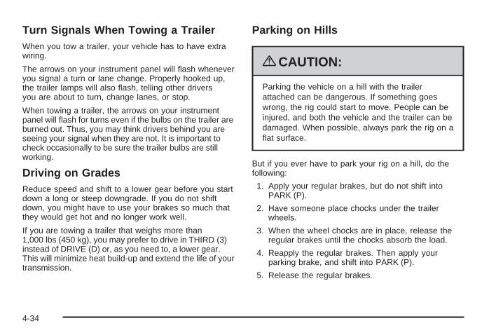
Turn Signals When Towing a TrailerWhen you tow a trailer, your vehicle has to have extrawiring.
The arrows on your instrument panel will flash wheneveryou signal a turn or lane change. Properly hooked up,the trailer lamps will also flash, telling other driversyou are about to turn, change lanes, or stop.
When towing a trailer, the arrows on your instrumentpanel will flash for turns even if the bulbs on the trailer areburned out. Thus, you may think drivers behind you areseeing your signal when they are not. It is important tocheck occasionally to be sure the trailer bulbs are stillworking.
Driving on GradesReduce speed and shift to a lower gear before you startdown a long or steep downgrade. If you do not shiftdown, you might have to use your brakes so much thatthey would get hot and no longer work well.
If you are towing a trailer that weighs more than1,000 lbs (450 kg), you may prefer to drive in THIRD (3)instead of DRIVE (D) or, as you need to, a lower gear.This will minimize heat build-up and extend the life of yourtransmission.
Parking on Hills
{CAUTION:
Parking the vehicle on a hill with the trailerattached can be dangerous. If something goeswrong, the rig could start to move. People can beinjured, and both the vehicle and the trailer can bedamaged. When possible, always park the rig on aflat surface.
But if you ever have to park your rig on a hill, do thefollowing:
1. Apply your regular brakes, but do not shift intoPARK (P).
2. Have someone place chocks under the trailerwheels.
3. When the wheel chocks are in place, release theregular brakes until the chocks absorb the load.
4. Reapply the regular brakes. Then apply yourparking brake, and shift into PARK (P).
5. Release the regular brakes.
4-34
When You Are Ready to Leave AfterParking on a Hill1. Apply your regular brakes and hold the pedal down
while you do the following:
• Start your engine.
• Shift into a gear.
• Release the parking brake.
2. Let up on the brake pedal.
3. Drive slowly until the trailer is clear of the chocks.
4. Stop and have someone pick up and store thechocks.
Maintenance When Trailer TowingYour vehicle will need service more often when you arepulling a trailer. See the Maintenance Schedule for moreon this. Things that are especially important in traileroperation are automatic transmission fluid, engine oil,belts, cooling system, and brake system. Each of these iscovered in this manual, and the Index will help you findthem quickly. If you are trailering, it is a good idea toreview these sections before you start your trip.
Check periodically to see that all hitch nuts and boltsare tight.
Trailer Wiring HarnessYour vehicle may have a trailer wiring harness packagelocated in the glove box. It can be connected fromthe rear of your vehicle to your trailer. Contact yourdealer/retailer for more information.
4-35

✍ NOTES
4-36
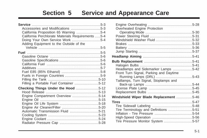
Service ............................................................5-3Accessories and Modifications ..........................5-3California Proposition 65 Warning .....................5-4California Perchlorate Materials Requirements .....5-4Doing Your Own Service Work .........................5-4Adding Equipment to the Outside of the
Vehicle ......................................................5-5Fuel ................................................................5-5
Gasoline Octane ............................................5-6Gasoline Specifications ....................................5-6California Fuel ...............................................5-6Additives .......................................................5-7Fuel E85 (85% Ethanol) ..................................5-8Fuels in Foreign Countries ...............................5-9Filling the Tank ............................................5-10Filling a Portable Fuel Container .....................5-12
Checking Things Under the Hood ....................5-12Hood Release ..............................................5-13Engine Compartment Overview .......................5-14Engine Oil ...................................................5-15Engine Oil Life System ..................................5-18Engine Air Cleaner/Filter ................................5-20Automatic Transmission Fluid .........................5-21Cooling System ............................................5-23Engine Coolant .............................................5-24Radiator Pressure Cap ..................................5-28
Engine Overheating .......................................5-28Overheated Engine Protection
Operating Mode .........................................5-30Power Steering Fluid .....................................5-31Windshield Washer Fluid ................................5-32Brakes ........................................................5-33Battery ........................................................5-36Jump Starting ...............................................5-37
Headlamp Aiming ...........................................5-41Bulb Replacement ..........................................5-41
Halogen Bulbs ..............................................5-41Headlamps and Sidemarker Lamps .................5-42Front Turn Signal, Parking and Daytime
Running Lamps (DRL) ................................5-43Taillamps, Turn Signal, Stoplamps and
Back-up Lamps .........................................5-44License Plate Lamp ......................................5-45Replacement Bulbs .......................................5-45
Windshield Wiper Blade Replacement ..............5-46Tires ..............................................................5-47
Tire Sidewall Labeling ...................................5-48Tire Terminology and Definitions .....................5-51Inflation - Tire Pressure .................................5-54High-Speed Operation ...................................5-56Tire Pressure Monitor System .........................5-57
Section 5 Service and Appearance Care
5-1
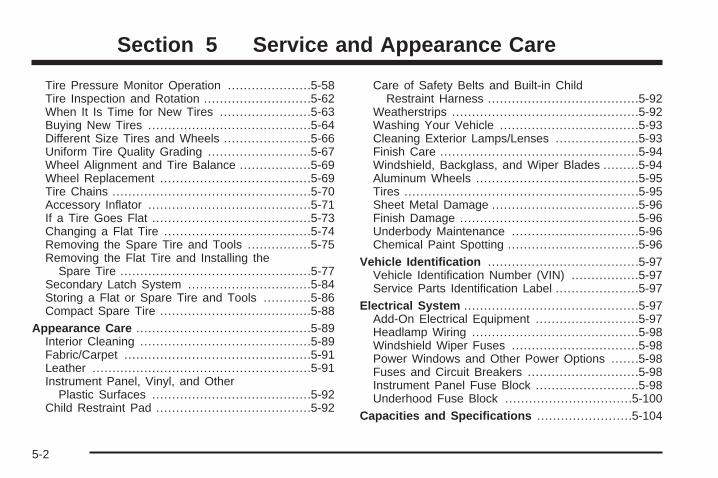
Tire Pressure Monitor Operation .....................5-58Tire Inspection and Rotation ...........................5-62When It Is Time for New Tires .......................5-63Buying New Tires .........................................5-64Different Size Tires and Wheels ......................5-66Uniform Tire Quality Grading ..........................5-67Wheel Alignment and Tire Balance ..................5-69Wheel Replacement ......................................5-69Tire Chains ..................................................5-70Accessory Inflator .........................................5-71If a Tire Goes Flat ........................................5-73Changing a Flat Tire .....................................5-74Removing the Spare Tire and Tools ................5-75Removing the Flat Tire and Installing the
Spare Tire ................................................5-77Secondary Latch System ...............................5-84Storing a Flat or Spare Tire and Tools ............5-86Compact Spare Tire ......................................5-88
Appearance Care ............................................5-89Interior Cleaning ...........................................5-89Fabric/Carpet ...............................................5-91Leather .......................................................5-91Instrument Panel, Vinyl, and Other
Plastic Surfaces ........................................5-92Child Restraint Pad .......................................5-92
Care of Safety Belts and Built-in ChildRestraint Harness ......................................5-92
Weatherstrips ...............................................5-92Washing Your Vehicle ...................................5-93Cleaning Exterior Lamps/Lenses .....................5-93Finish Care ..................................................5-94Windshield, Backglass, and Wiper Blades .........5-94Aluminum Wheels .........................................5-95Tires ...........................................................5-95Sheet Metal Damage .....................................5-96Finish Damage .............................................5-96Underbody Maintenance ................................5-96Chemical Paint Spotting .................................5-96
Vehicle Identification ......................................5-97Vehicle Identification Number (VIN) .................5-97Service Parts Identification Label .....................5-97
Electrical System ............................................5-97Add-On Electrical Equipment ..........................5-97Headlamp Wiring ..........................................5-98Windshield Wiper Fuses ................................5-98Power Windows and Other Power Options .......5-98Fuses and Circuit Breakers ............................5-98Instrument Panel Fuse Block ..........................5-98Underhood Fuse Block ................................5-100
Capacities and Specifications ........................5-104
Section 5 Service and Appearance Care
5-2
ServiceFor service and parts needs, visit your dealer/retailer.You will receive genuine GM parts and GM-trained andsupported service people.
Genuine GM parts have one of these marks:
Accessories and ModificationsWhen non-dealer/non-retailer accessories are addedto the vehicle, they can affect vehicle performance andsafety, including such things as airbags, braking, stability,ride and handling, emissions systems, aerodynamics,durability, and electronic systems like antilock brakes,traction control, and stability control. Some of theseaccessories could even cause malfunction or damagenot covered by the vehicle warranty.
GM Accessories are designed to complement andfunction with other systems on the vehicle. Your GMdealer/retailer can accessorize the vehicle usinggenuine GM Accessories. When you go to your GMdealer/retailer and ask for GM Accessories, youwill know that GM-trained and supported servicetechnicians will perform the work using genuineGM Accessories.
Also, see Adding Equipment to Your Airbag-EquippedVehicle on page 1-91.
5-3
California Proposition 65 WarningMost motor vehicles, including this one, contain and/oremit chemicals known to the State of California to causecancer and birth defects or other reproductive harm.Engine exhaust, many parts and systems (includingsome inside the vehicle), many fluids, and somecomponent wear by-products contain and/or emitthese chemicals.
California Perchlorate MaterialsRequirementsCertain types of automotive applications, such asairbag initiators, seat belt pretensioners, and lithiumbatteries contained in remote keyless transmitters,may contain perchlorate materials. Special handlingmay be necessary. For additional information, seewww.dtsc.ca.gov/hazardouswaste/perchlorate.
Doing Your Own Service Work
{CAUTION:
You can be injured and the vehicle could bedamaged if you try to do service work on a vehiclewithout knowing enough about it.
• Be sure you have sufficient knowledge,experience, the proper replacement parts,and tools before attempting any vehiclemaintenance task.
• Be sure to use the proper nuts, bolts, andother fasteners. English and metric fastenerscan be easily confused. If the wrong fastenersare used, parts can later break or fall off.You could be hurt.
5-4
If doing some of your own service work, use the properservice manual. It tells you much more about how toservice the vehicle than this manual can. To orderthe proper service manual, see Service PublicationsOrdering Information on page 7-15.
This vehicle has an airbag system. Before attemptingto do your own service work, see Servicing YourAirbag-Equipped Vehicle on page 1-90.
Keep a record with all parts receipts and list themileage and the date of any service work performed.See Maintenance Record on page 6-15.
Adding Equipment to the Outside ofthe VehicleThings added to the outside of the vehicle can affect theairflow around it. This can cause wind noise and canaffect fuel economy and windshield washer performance.Check with your dealer/retailer before adding equipmentto the outside of the vehicle.
FuelUse of the recommended fuel is an important part ofthe proper maintenance of this vehicle. To help keep theengine clean and maintain optimum vehicle performance,we recommend the use of gasoline advertised as TOPTIER Detergent Gasoline.
The 8th digit of the Vehicle Identification Number (VIN)shows the code letter or number that identifies thevehicle’s engine. The VIN is at the top left of theinstrument panel. See Vehicle Identification Number(VIN) on page 5-97.
If the vehicle has the 3.9L V6 engine (VIN Code W),you can use either unleaded gasoline or ethanol fuelcontaining up to 85% ethanol (E85). See Fuel E85(85% Ethanol) on page 5-8. If your vehicle has the3.9L V6 engine (VIN Code 1), use only regular unleadedgasoline.
5-5
Gasoline OctaneUse regular unleaded gasoline with a posted octanerating of 87 or higher. If the octane rating is less than 87,you might notice an audible knocking noise when youdrive, commonly referred to as spark knock. If thisoccurs, use a gasoline rated at 87 octane or higher assoon as possible. If you are using gasoline rated at87 octane or higher and you hear heavy knocking,the engine needs service.
Gasoline SpecificationsAt a minimum, gasoline should meet ASTMspecification D 4814 in the United States orCAN/CGSB-3.5 or 3.511 in Canada. Some gasolinescontain an octane-enhancing additive calledmethylcyclopentadienyl manganese tricarbonyl (MMT).We recommend against the use of gasolinescontaining MMT. See Additives on page 5-7for additional information.
California FuelIf the vehicle is certified to meet California EmissionsStandards, it is designed to operate on fuels that meetCalifornia specifications. See the underhood emissioncontrol label. If this fuel is not available in states adoptingCalifornia emissions standards, the vehicle will operatesatisfactorily on fuels meeting federal specifications, butemission control system performance might be affected.The malfunction indicator lamp could turn on and thevehicle might fail a smog-check test. See MalfunctionIndicator Lamp on page 3-38. If this occurs, return to yourauthorized dealer/retailer for diagnosis. If it is determinedthat the condition is caused by the type of fuel used,repairs might not be covered by the vehicle warranty.
5-6
AdditivesTo provide cleaner air, all gasolines in the United Statesare now required to contain additives that help preventengine and fuel system deposits from forming, allowingthe emission control system to work properly. In mostcases, you should not have to add anything to the fuel.However, some gasolines contain only the minimumamount of additive required to meet U.S. EnvironmentalProtection Agency regulations. To help keep fuel injectorsand intake valves clean, or if the vehicle experiencesproblems due to dirty injectors or valves, look for gasolinethat is advertised as TOP TIER Detergent Gasoline. Also,your dealer/retailer has additives that will help correct andprevent most deposit-related problems.
Gasolines containing oxygenates, such as ethers andethanol, and reformulated gasolines might be available inyour area. We recommend that you use these gasolines,if they comply with the specifications described earlier.However, E85 (85% ethanol) and other fuels containingmore than 10% ethanol must not be used in vehicles thatwere not designed for those fuels.
Notice: This vehicle was not designed for fuel thatcontains methanol. Do not use fuel containingmethanol. It can corrode metal parts in the fuelsystem and also damage plastic and rubber parts.That damage would not be covered under thevehicle warranty.
Some gasolines that are not reformulated forlow emissions can contain an octane-enhancingadditive called methylcyclopentadienyl manganesetricarbonyl (MMT); ask the attendant where you buygasoline whether the fuel contains MMT. We recommendagainst the use of such gasolines. Fuels containing MMTcan reduce the life of spark plugs and the performanceof the emission control system could be affected. Themalfunction indicator lamp might turn on. If this occurs,return to your dealer/retailer for service.
5-7
Fuel E85 (85% Ethanol)The 8th digit of the Vehicle Identification Number (VIN)shows the code letter or number that identifies thevehicle’s engine. The VIN is at the top left of theinstrument panel. See Vehicle Identification Number(VIN) on page 5-97.
If the vehicle has the 3.9L V6 engine (VIN Code W),you can use either unleaded gasoline or ethanolfuel containing up to 85% ethanol (E85). See Fuel onpage 5-5. In all other engines, use only the unleadedgasoline described under Gasoline Octane on page 5-6.
Only vehicles that have the 3.9L V6 engine(VIN Code W) can use 85% ethanol fuel (E85).We encourage the use of E85 in vehicles that aredesigned to use it. The ethanol in E85 is a “renewable”fuel, meaning it is made from renewable sources suchas corn and other crops.
Many service stations will not have an 85% ethanolfuel (E85) pump available. The U. S. Departmentof Energy has an alternative fuels website(www.eere.energy.gov/afdc/infrastructure/locator.html)that can help you find E85 fuel. Those stations that dohave E85 should have a label indicating ethanol content.Do not use the fuel if the ethanol content is greaterthan 85%.
At a minimum, E85 should meet ASTM SpecificationD 5798. By definition, this means that fuel labeled E85will have an ethanol content between 70% and 85%.Filling the fuel tank with fuel mixtures that do not meetASTM specifications can affect drivability and couldcause the malfunction indicator lamp to come on.
To ensure quick starts in the wintertime, the E85 fuelmust be formulated properly for your climate accordingto ASTM specification D 5798. If you have troublestarting on E85, it could be because the E85 fuel is notproperly formulated for your climate. If this happens,switching to gasoline or adding gasoline to the fuel tankcan improve starting. For good starting and heaterefficiency below 32°F (0°C), the fuel mix in the fuel tankshould contain no more than 70% ethanol. It is bestnot to alternate repeatedly between gasoline and E85.
5-8
If you do switch fuels, it is recommended that youadd as much fuel as possible — do not add less thanthree gallons (11 L) when refueling. You should drivethe vehicle immediately after refueling for at leastseven miles (11 km) to allow the vehicle to adapt tothe change in ethanol concentration.
E85 has less energy per gallon than gasoline, so youwill need to refill the fuel tank more often when using E85than when you are using gasoline. See Filling the Tankon page 5-10.
Notice: Some additives are not compatible withE85 fuel and can harm the vehicle’s fuel system.Do not add anything to E85. Damage causedby additives would not be covered by the vehiclewarranty.
Notice: This vehicle was not designed for fuel thatcontains methanol. Do not use fuel containingmethanol. It can corrode metal parts in the fuelsystem and also damage plastic and rubber parts.That damage would not be covered under thevehicle warranty.
Fuels in Foreign CountriesIf you plan on driving in another country outside theUnited States or Canada, the proper fuel might be hardto find. Never use leaded gasoline or any other fuelnot recommended in the previous text on fuel. Costlyrepairs caused by use of improper fuel would notbe covered by the vehicle warranty.
To check the fuel availability, ask an auto club, orcontact a major oil company that does business inthe country where you will be driving.
5-9
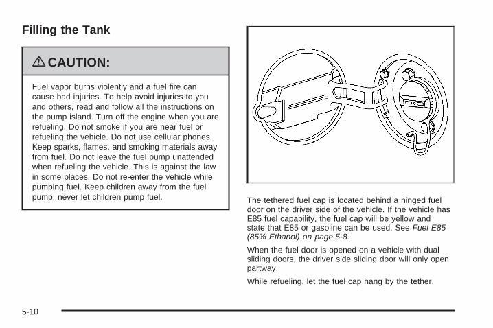
Filling the Tank
{CAUTION:
Fuel vapor burns violently and a fuel fire cancause bad injuries. To help avoid injuries to youand others, read and follow all the instructions onthe pump island. Turn off the engine when you arerefueling. Do not smoke if you are near fuel orrefueling the vehicle. Do not use cellular phones.Keep sparks, flames, and smoking materials awayfrom fuel. Do not leave the fuel pump unattendedwhen refueling the vehicle. This is against the lawin some places. Do not re-enter the vehicle whilepumping fuel. Keep children away from the fuelpump; never let children pump fuel. The tethered fuel cap is located behind a hinged fuel
door on the driver side of the vehicle. If the vehicle hasE85 fuel capability, the fuel cap will be yellow andstate that E85 or gasoline can be used. See Fuel E85(85% Ethanol) on page 5-8.
When the fuel door is opened on a vehicle with dualsliding doors, the driver side sliding door will only openpartway.
While refueling, let the fuel cap hang by the tether.
5-10
{CAUTION:
Fuel can spray out on you if you open the fuel captoo quickly. If you spill fuel and then somethingignites it, you could be badly burned. This spraycan happen if the tank is nearly full, and is morelikely in hot weather. Open the fuel cap slowly andwait for any hiss noise to stop. Then unscrew thecap all the way.
Be careful not to spill fuel. Do not top off or overfill thetank and wait a few seconds. Finish pumping beforeremoving the nozzle. Clean fuel from painted surfacesas soon as possible. See Washing Your Vehicle onpage 5-93.
When replacing the fuel cap, turn it clockwise until itclicks. Make sure the cap is fully installed. The diagnosticsystem can determine if the fuel cap has been left off orimproperly installed. This would allow fuel to evaporateinto the atmosphere. See Malfunction Indicator Lamp onpage 3-38.
The CHECK GAS CAP message displays in the DriverInformation Center (DIC) if the fuel cap is not properlyinstalled. See DIC Warnings and Messages onpage 3-51 for more information.
{CAUTION:
If a fire starts while you are refueling, do notremove the nozzle. Shut off the flow of fuel byshutting off the pump or by notifying the stationattendant. Leave the area immediately.
Notice: If you need a new fuel cap, be sure to getthe right type. Your dealer/retailer can get onefor you. If you get the wrong type, it may not fitproperly. This may cause the malfunction indicatorlamp to light and may damage the fuel tank andemissions system. See Malfunction Indicator Lampon page 3-38.
5-11
Filling a Portable Fuel Container
{CAUTION:
Never fill a portable fuel container while it is inthe vehicle. Static electricity discharge from thecontainer can ignite the fuel vapor. You can bebadly burned and the vehicle damaged if thisoccurs. To help avoid injury to you and others:
• Dispense fuel only into approved containers.• Do not fill a container while it is inside a
vehicle, in a vehicle’s trunk, pickup bed,or on any surface other than the ground.
• Bring the fill nozzle in contact with the insideof the fill opening before operating the nozzle.Contact should be maintained until the fillingis complete.
• Do not smoke while pumping fuel.• Do not use a cellular phone while
pumping fuel.
Checking Things Underthe Hood
{CAUTION:
An electric fan under the hood can start up andinjure you even when the engine is not running.Keep hands, clothing, and tools away from anyunderhood electric fan.
{CAUTION:
Things that burn can get on hot engine parts andstart a fire. These include liquids like fuel, oil,coolant, brake fluid, windshield washer and otherfluids, and plastic or rubber. You or others couldbe burned. Be careful not to drop or spill thingsthat will burn onto a hot engine.
5-12
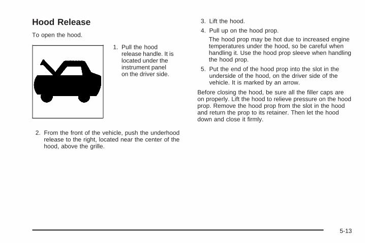
Hood ReleaseTo open the hood.
1. Pull the hoodrelease handle. It islocated under theinstrument panelon the driver side.
2. From the front of the vehicle, push the underhoodrelease to the right, located near the center of thehood, above the grille.
3. Lift the hood.
4. Pull up on the hood prop.The hood prop may be hot due to increased enginetemperatures under the hood, so be careful whenhandling it. Use the hood prop sleeve when handlingthe hood prop.
5. Put the end of the hood prop into the slot in theunderside of the hood, on the driver side of thevehicle. It is marked by an arrow.
Before closing the hood, be sure all the filler caps areon properly. Lift the hood to relieve pressure on the hoodprop. Remove the hood prop from the slot in the hoodand return the prop to its retainer. Then let the hooddown and close it firmly.
5-13
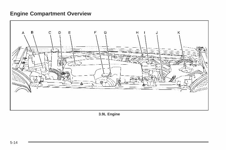
Engine Compartment Overview
3.9L Engine
5-14
A. Underhood Fuse Block. See Underhood Fuse Blockon page 5-100.
B. Remote Positive (+) Terminal. See Jump Starting onpage 5-37.
C. Windshield Washer Fluid Reservoir. See “AddingWasher Fluid” under Windshield Washer Fluidon page 5-32.
D. Radiator Pressure Cap. See Radiator Pressure Capon page 5-28.
E. Power Steering Fluid Reservoir. See Power SteeringFluid on page 5-31.
F. Engine Oil Fill Cap. See “When to Add Engine Oil”under Engine Oil on page 5-15.
G. Engine Oil Dipstick. See “Checking Engine Oil”under Engine Oil on page 5-15.
H. Automatic Transmission Fluid Dipstick.See “Checking the Fluid Level” under AutomaticTransmission Fluid on page 5-21.
I. Brake Master Cylinder Reservoir. See “Brake Fluid”under Brakes on page 5-33.
J. Engine Air Cleaner/Filter. See Engine AirCleaner/Filter on page 5-20.
K. Engine Coolant Recovery Tank. See Cooling Systemon page 5-23.
Engine Oil
Checking Engine OilIt is a good idea to check the engine oil every time youget fuel. In order to get an accurate reading, the oilmust be warm and the vehicle must be on level ground.
The engine oil dipstick handle is a yellow loop.See Engine Compartment Overview on page 5-14for the location of the engine oil dipstick.
1. Turn off the engine and give the oil several minutesto drain back into the oil pan. If you do not do this,the oil dipstick might not show the actual level.
2. Pull out the dipstick and clean it with a paper towelor cloth, then push it back in all the way. Remove itagain, keeping the tip down, and check the level.
5-15
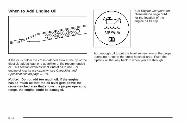
When to Add Engine Oil
If the oil is below the cross-hatched area at the tip of thedipstick, add at least one quart/liter of the recommendedoil. This section explains what kind of oil to use. Forengine oil crankcase capacity, see Capacities andSpecifications on page 5-104.
Notice: Do not add too much oil. If the enginehas so much oil that the oil level gets above thecross-hatched area that shows the proper operatingrange, the engine could be damaged.
See Engine CompartmentOverview on page 5-14for the location of theengine oil fill cap.
Add enough oil to put the level somewhere in the properoperating range in the cross-hatched area. Push thedipstick all the way back in when you are through.
5-16

What Kind of Engine Oil to UseLook for three things:
• GM6094M
Use only an oil that meets GM Standard GM6094M.
• SAE 5W-30
SAE 5W-30 is best for the vehicle. If you are inan area of extreme cold, where the temperature fallsbelow −20°F (−29°C), use either an SAE 5W-30
synthetic oil or an SAE 0W-30 oil. Both provideeasier cold starting and better protection forthe engine at extremely low temperatures.These numbers on an oil container show itsviscosity, or thickness. Do not use other viscosityoils such as SAE 20W-50.
• American Petroleum Institute (API) starburst symbol
Oils meeting theserequirements should havethe starburst symbol onthe container. This symbolindicates that the oilhas been certified bythe American PetroleumInstitute (API).
Notice: Use only engine oil identified as meetingGM Standard GM6094M and showing the AmericanPetroleum Institute Certified For Gasoline Enginesstarburst symbol. Failure to use the recommendedoil can result in engine damage not covered bythe vehicle warranty.
5-17
Engine Oil Additives / Engine OilFlushesDo not add anything to the oil. The recommendedoils with the starburst symbol that meet GMStandard GM6094M are all you need for goodperformance and engine protection.
Engine oil system flushes are not recommended andcould cause engine damage not covered by the vehiclewarranty.
Engine Oil Life System
When to Change Engine OilThis vehicle has a computer system that lets you knowwhen to change the engine oil and filter. This is basedon engine revolutions and engine temperature, and noton mileage. Based on driving conditions, the mileageat which an oil change will be indicated can varyconsiderably. For the oil life system to work properly,you must reset the system every time the oil is changed.
When the system has calculated that oil life has beendiminished, it will indicate that an oil change is necessary.A CHANGE OIL SOON message will come on. See DICWarnings and Messages on page 3-51. Change the oilas soon as possible within the next 600 miles (1 000 km).It is possible that, if you are driving under the bestconditions, the oil life system might not indicate that an oilchange is necessary for over a year. However, the engineoil and filter must be changed at least once a year and atthis time the system must be reset. Your dealer/retailerhas trained people who will perform this work usinggenuine parts and reset the system. It is also importantto check the oil regularly and keep it at the proper level.
If the system is ever reset accidentally, you mustchange the oil at 3,000 miles (5 000 km) since the last oilchange. Remember to reset the oil life system wheneverthe oil is changed.
5-18
How to Reset the Engine Oil LifeSystemThe Engine Oil Life System calculates when to changethe engine oil and filter based on vehicle use. Wheneverthe oil is changed, reset the system so it can calculatewhen the next oil change is required. If a situation occurswhere you change the oil prior to a CHANGE OIL SOONmessage being turned on, reset the system.
1. With the ignition key in ON/RUN but the engine off,repeatedly push the set/reset button until OIL isdisplayed on the Driver Information Center (DIC).
2. Once OIL is displayed, push and hold the set/resetbutton for five seconds. The number will disappearand be replaced by 100 (indicating 100% oil liferemaining).
3. Turn the key to LOCK/OFF.
If the CHANGE OIL SOON message comes back onwhen you start the vehicle, the engine oil life system hasnot reset. Repeat the procedure.
What to Do with Used OilUsed engine oil contains certain elements that can beunhealthy for your skin and could even cause cancer.Do not let used oil stay on your skin for very long.Clean your skin and nails with soap and water, ora good hand cleaner. Wash or properly disposeof clothing or rags containing used engine oil.See the manufacturer’s warnings about the useand disposal of oil products.
Used oil can be a threat to the environment. If youchange your own oil, be sure to drain all the oil from thefilter before disposal. Never dispose of oil by putting itin the trash, pouring it on the ground, into sewers, or intostreams or bodies of water. Recycle it by taking it to aplace that collects used oil.
5-19
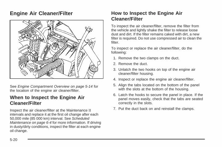
Engine Air Cleaner/Filter
See Engine Compartment Overview on page 5-14 forthe location of the engine air cleaner/filter.
When to Inspect the Engine AirCleaner/FilterInspect the air cleaner/filter at the Maintenance IIintervals and replace it at the first oil change after each50,000 mile (85 000 km) interval. See ScheduledMaintenance on page 6-4 for more information. If drivingin dusty/dirty conditions, inspect the filter at each engineoil change.
How to Inspect the Engine AirCleaner/FilterTo inspect the air cleaner/filter, remove the filter fromthe vehicle and lightly shake the filter to release loosedust and dirt. If the filter remains caked with dirt, a newfilter is required. Do not use compressed air to clean thefilter.
To inspect or replace the air cleaner/filter, do thefollowing:
1. Remove the two clamps on the duct.
2. Remove the duct.
3. Unlatch the two hooks on top of the engine aircleaner/filter housing.
4. Inspect or replace the engine air cleaner/filter.
5. Align the tabs located on the bottom of the panelwith the slots at the bottom of the housing.
6. Latch the hooks to secure the panel in place. If thepanel moves easily, check that the tabs are seatedcorrectly in the slots.
7. Put the duct back on and reinstall the clamps.
5-20

{CAUTION:
Operating the engine with the air cleaner/filter offcan cause you or others to be burned. The aircleaner not only cleans the air; it helps to stopflames if the engine backfires. If it is not there andthe engine backfires, you could be burned. Do notdrive with it off, and be careful working on theengine with the air cleaner/filter off.
Notice: If the air cleaner/filter is off, a backfire cancause a damaging engine fire. And, dirt can easily getinto the engine, which will damage it. Always havethe air cleaner/filter in place when you are driving.
Automatic Transmission FluidWhen to Check and Change AutomaticTransmission FluidA good time to check the automatic transmission fluidlevel is when the engine oil is changed.
Change the fluid and filter at the intervals listed inAdditional Required Services on page 6-6, and be sureto use the transmission fluid listed in RecommendedFluids and Lubricants on page 6-11.
How to Check Automatic TransmissionFluidBecause this operation can be a little difficult, you maychoose to have this done at the dealer/retailer servicedepartment.If you do it yourself, be sure to follow all the instructionshere, or you could get a false reading on the dipstick.
Notice: Too much or too little fluid can damageyour transmission. Too much can mean that someof the fluid could come out and fall on hot engineparts or exhaust system parts, starting a fire.Too little fluid could cause the transmission tooverheat. Be sure to get an accurate reading ifyou check your transmission fluid.Wait at least 30 minutes before checking thetransmission fluid level if vehicle has been driven:• When outside temperatures are above 90°F (32°C).• At high speed for quite a while.• In heavy traffic — especially in hot weather.• While pulling a trailer.
To get the right reading, the fluid should be at normaloperating temperature, which is 180°F to 200°F(82°C to 93°C).Get the vehicle warmed up by driving about 15 miles(24 km) when outside temperatures are above 50°F(10°C). If it is colder than 50°F (10°C), drive longer.
5-21
Checking the Fluid LevelPrepare the vehicle as follows:1. Park the vehicle on a level place. Keep the engine
running.2. With the parking brake applied, place the shift lever
in P (Park).3. With the foot on the brake pedal, move the shift
lever through each gear range, pausing for aboutthree seconds in each range. Then, positionthe shift lever in P (Park).
4. Let the engine run at idle for three to five minutes.Then, without shutting off the engine, follow these steps:1. Pull out the dipstick and wipe it with a clean rag or
paper towel.The automatic transmission dipstick is locatedtoward the back of the engine compartment, nearthe brake master cylinder reservoir. The dipstickhandle is a red loop. See Engine CompartmentOverview on page 5-14 for more informationon location.
2. Push it back in all the way, wait three seconds, andthen pull it back out again.
3. Check both sides of the dipstick, and read thelower level. The fluid level must be in thecross-hatched area.
4. If the fluid level is in the acceptable range, push thedipstick back in all the way.
How to Add Automatic TransmissionFluidRefer to the Maintenance Schedule to determine whatkind of transmission fluid to use. See RecommendedFluids and Lubricants on page 6-11.
If the fluid level is low, add only enough of the properfluid to bring the level into the cross-hatched area on thedipstick.
1. Pull out the dipstick.
2. Using a long-neck funnel, add enough fluid at thedipstick hole to bring it to the proper level.It does not take much fluid, generally less thanone pint (0.5 L). Do not overfill.
Notice: Use of the incorrect automatic transmissionfluid may damage the vehicle, and the damagesmay not be covered by the vehicle’s warranty.Always use the automatic transmission fluid listedin Recommended Fluids and Lubricants onpage 6-11.
3. After adding fluid, recheck the fluid level asdescribed under “How to Check AutomaticTransmission Fluid,” earlier in this section.
4. When the correct fluid level is obtained, push thedipstick back in all the way.
5-22
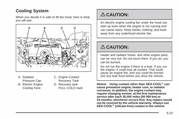
Cooling SystemWhen you decide it is safe to lift the hood, here is whatyou will see:
A. RadiatorPressure Cap
B. Electric EngineCooling Fans
C. Engine CoolantRecovery Tank
D. Recovery tankFULL COLD mark
{CAUTION:
An electric engine cooling fan under the hood canstart up even when the engine is not running andcan cause injury. Keep hands, clothing, and toolsaway from any underhood electric fan.
{CAUTION:
Heater and radiator hoses, and other engine parts,can be very hot. Do not touch them. If you do, youcan be burned.Do not run the engine if there is a leak. If you runthe engine, it could lose all coolant. That couldcause an engine fire, and you could be burned.Get any leak fixed before you drive the vehicle.
Notice: Using coolant other than DEX-COOL® cancause premature engine, heater core, or radiatorcorrosion. In addition, the engine coolant mayrequire changing sooner, at the first maintenanceservice after each 30,000 miles (50 000 km) or24 months, whichever occurs first. Any repairs wouldnot be covered by the vehicle warranty. Always useDEX-COOL® (silicate-free) coolant in the vehicle.
5-23
Engine CoolantThe cooling system in the vehicle is filled withDEX-COOL® engine coolant. This coolant is designedto remain in the vehicle for five years or 150,000 miles(240 000 km), whichever occurs first.
The following explains the cooling system and how tocheck and add coolant when it is low. If there is aproblem with engine overheating, see EngineOverheating on page 5-28
What to Use
{CAUTION:
Adding only plain water to the cooling system canbe dangerous. Plain water, or some other liquidsuch as alcohol, can boil before the proper coolantmixture will. The vehicle’s coolant warning systemis set for the proper coolant mixture. With plainwater or the wrong mixture, the engine could gettoo hot but you would not get the overheatwarning. The engine could catch fire and you orothers could be burned. Use a 50/50 mixture ofclean, drinkable water and DEX-COOL® coolant.
Use a 50/50 mixture of clean, drinkable water andDEX-COOL® coolant. If using this mixture, nothing elseneeds to be added. This mixture:
• Gives freezing protection down to −34°F (−37°C),outside temperature.
• Gives boiling protection up to 265°F (129°C),engine temperature.
• Protects against rust and corrosion.
• Will not damage aluminum parts.
• Helps keep the proper engine temperature.
Notice: If an improper coolant mixture is used,the engine could overheat and be badly damaged.The repair cost would not be covered by the vehiclewarranty. Too much water in the mixture can freezeand crack the engine, radiator, heater core, and otherparts.
Notice: If extra inhibitors and/or additives are usedin the vehicle’s cooling system, the vehicle couldbe damaged. Use only the proper mixture ofthe engine coolant listed in this manual for thecooling system. See Recommended Fluids andLubricants on page 6-11 for more information.
If coolant needs to be added more than four times ayear, have the dealer/retailer check the cooling system.
5-24
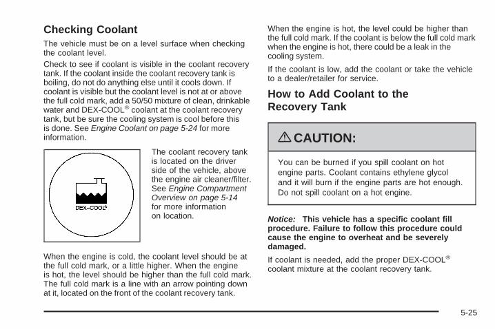
Checking CoolantThe vehicle must be on a level surface when checkingthe coolant level.Check to see if coolant is visible in the coolant recoverytank. If the coolant inside the coolant recovery tank isboiling, do not do anything else until it cools down. Ifcoolant is visible but the coolant level is not at or abovethe full cold mark, add a 50/50 mixture of clean, drinkablewater and DEX-COOL® coolant at the coolant recoverytank, but be sure the cooling system is cool before thisis done. See Engine Coolant on page 5-24 for moreinformation.
The coolant recovery tankis located on the driverside of the vehicle, abovethe engine air cleaner/filter.See Engine CompartmentOverview on page 5-14for more informationon location.
When the engine is cold, the coolant level should be atthe full cold mark, or a little higher. When the engineis hot, the level should be higher than the full cold mark.The full cold mark is a line with an arrow pointing downat it, located on the front of the coolant recovery tank.
When the engine is hot, the level could be higher thanthe full cold mark. If the coolant is below the full cold markwhen the engine is hot, there could be a leak in thecooling system.
If the coolant is low, add the coolant or take the vehicleto a dealer/retailer for service.
How to Add Coolant to theRecovery Tank
{CAUTION:
You can be burned if you spill coolant on hotengine parts. Coolant contains ethylene glycoland it will burn if the engine parts are hot enough.Do not spill coolant on a hot engine.
Notice: This vehicle has a specific coolant fillprocedure. Failure to follow this procedure couldcause the engine to overheat and be severelydamaged.
If coolant is needed, add the proper DEX-COOL®
coolant mixture at the coolant recovery tank.
5-25
How to Add Coolant to the Radiator
Notice: Your engine has a specific radiatorfill procedure. Failure to follow this procedure couldcause your engine to overheat and be severelydamaged.
{CAUTION:
An electric engine cooling fan under the hood canstart up even when the engine is not running andcan cause injury. Keep hands, clothing, and toolsaway from any underhood electric fan.
{CAUTION:
Steam and scalding liquids from a hot coolingsystem can blow out and burn you badly. Theyare under pressure, and if you turn the radiatorpressure cap — even a little — they can comeout at high speed. Never turn the cap when thecooling system, including the radiator pressure cap,is hot. Wait for the cooling system and radiatorpressure cap to cool if you ever have to turn thepressure cap.
5-26
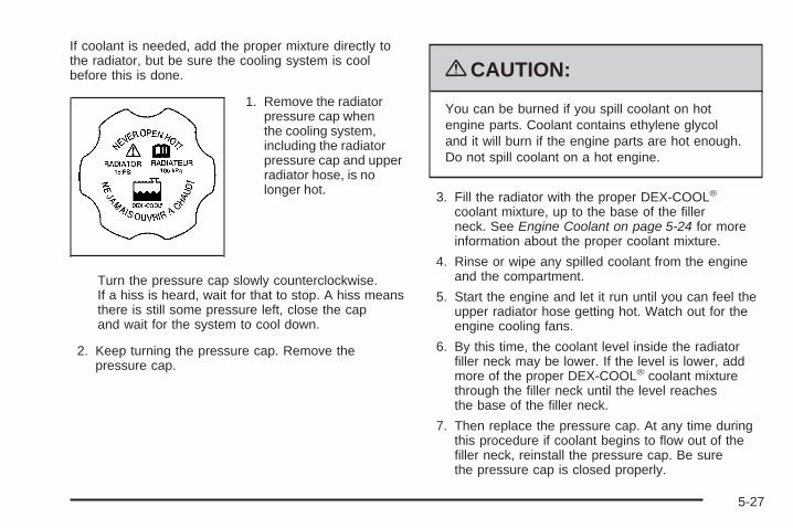
If coolant is needed, add the proper mixture directly tothe radiator, but be sure the cooling system is coolbefore this is done.
1. Remove the radiatorpressure cap whenthe cooling system,including the radiatorpressure cap and upperradiator hose, is nolonger hot.
Turn the pressure cap slowly counterclockwise.If a hiss is heard, wait for that to stop. A hiss meansthere is still some pressure left, close the capand wait for the system to cool down.
2. Keep turning the pressure cap. Remove thepressure cap.
{CAUTION:
You can be burned if you spill coolant on hotengine parts. Coolant contains ethylene glycoland it will burn if the engine parts are hot enough.Do not spill coolant on a hot engine.
3. Fill the radiator with the proper DEX-COOL®
coolant mixture, up to the base of the fillerneck. See Engine Coolant on page 5-24 for moreinformation about the proper coolant mixture.
4. Rinse or wipe any spilled coolant from the engineand the compartment.
5. Start the engine and let it run until you can feel theupper radiator hose getting hot. Watch out for theengine cooling fans.
6. By this time, the coolant level inside the radiatorfiller neck may be lower. If the level is lower, addmore of the proper DEX-COOL® coolant mixturethrough the filler neck until the level reachesthe base of the filler neck.
7. Then replace the pressure cap. At any time duringthis procedure if coolant begins to flow out of thefiller neck, reinstall the pressure cap. Be surethe pressure cap is closed properly.
5-27
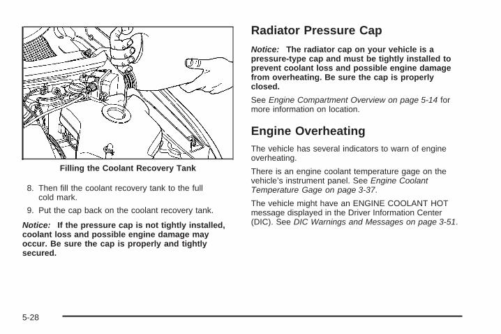
8. Then fill the coolant recovery tank to the fullcold mark.
9. Put the cap back on the coolant recovery tank.
Notice: If the pressure cap is not tightly installed,coolant loss and possible engine damage mayoccur. Be sure the cap is properly and tightlysecured.
Radiator Pressure CapNotice: The radiator cap on your vehicle is apressure-type cap and must be tightly installed toprevent coolant loss and possible engine damagefrom overheating. Be sure the cap is properlyclosed.
See Engine Compartment Overview on page 5-14 formore information on location.
Engine OverheatingThe vehicle has several indicators to warn of engineoverheating.
There is an engine coolant temperature gage on thevehicle’s instrument panel. See Engine CoolantTemperature Gage on page 3-37.
The vehicle might have an ENGINE COOLANT HOTmessage displayed in the Driver Information Center(DIC). See DIC Warnings and Messages on page 3-51.
Filling the Coolant Recovery Tank
5-28
You may decide not to lift the hood when this warningappears, but instead get service help right away.See Roadside Assistance Program on page 7-7.
If you do decide to lift the hood, make sure the vehicleis parked on a level surface
Then check to see if the engine cooling fans arerunning. If the engine is overheating, both fans shouldbe running. If they are not, do not continue to runthe engine and have the vehicle serviced.
Notice: Engine damage from running your enginewithout coolant is not covered by your warranty.See Overheated Engine Protection Operating Modeon page 5-30 for information on driving to a safeplace in an emergency.
Notice: If the engine catches fire while driving withno coolant, the vehicle can be badly damaged.The costly repairs would not be covered bythe vehicle warranty. See Overheated EngineProtection Operating Mode on page 5-30 forinformation on driving to a safe place in anemergency.
If Steam Is Coming From The EngineCompartment
{CAUTION:
Steam from an overheated engine can burn youbadly, even if you just open the hood. Stay awayfrom the engine if you see or hear steam comingfrom it. Turn it off and get everyone away from thevehicle until it cools down. Wait until there is no signof steam or coolant before you open the hood.
If you keep driving when the vehicle’s engine isoverheated, the liquids in it can catch fire. You orothers could be badly burned. Stop the engine if itoverheats, and get out of the vehicle until theengine is cool.
See Overheated Engine Protection Operating Modeon page 5-30 for information on driving to a safeplace in an emergency.
5-29
If No Steam Is Coming From TheEngine CompartmentIf an engine overheat warning is displayed but no steamcan be seen or heard, the problem may not be tooserious. Sometimes the engine can get a little too hotwhen the vehicle:
• Climbs a long hill on a hot day.
• Stops after high-speed driving.
• Idles for long periods in traffic.
• Tows a trailer.
If the overheat warning is displayed with no sign ofsteam:
1. Turn the air off.
2. Turn the heater on to the highest temperature andto the highest fan speed. Open the windows asnecessary.
3. If in a traffic jam, shift to N (Neutral), otherwise,shift to the highest gear while driving — D (Drive)or L (Low).
If the temperature overheat gage is no longer in theoverheat zone or an overheat warning no longer displays,the vehicle can be driven. Continue to drive the vehicleslow for about 10 minutes. Keep a safe vehicle distancefrom the car in front of you. If the warning does not comeback on, continue to drive normally.
If the warning continues, pull over, stop, and park thevehicle right away.
If there is no sign of steam, idle the engine forthree minutes while parked. If the warning is stilldisplayed, turn off the engine until it cools down. Also,see “Overheated Engine Protection Operating Mode”later in this section.
Overheated Engine ProtectionOperating ModeThis emergency operating mode lets the vehiclebe driven to a safe place in an emergency situation.If an overheated engine condition exists, an overheatprotection mode which alternates firing groups ofcylinders helps prevent engine damage. In this mode,there is a significant loss in power and engineperformance. The temperature gage indicates anoverheat condition exists. Driving extended distancesand/or towing a trailer in the overheat protection modeshould be avoided.
Notice: After driving in the overheated engineprotection operating mode, to avoid engine damage,allow the engine to cool before attempting anyrepair. The engine oil will be severely degraded.Repair the cause of coolant loss, change the oil andreset the oil life system. See Engine Oil on page 5-15.
5-30
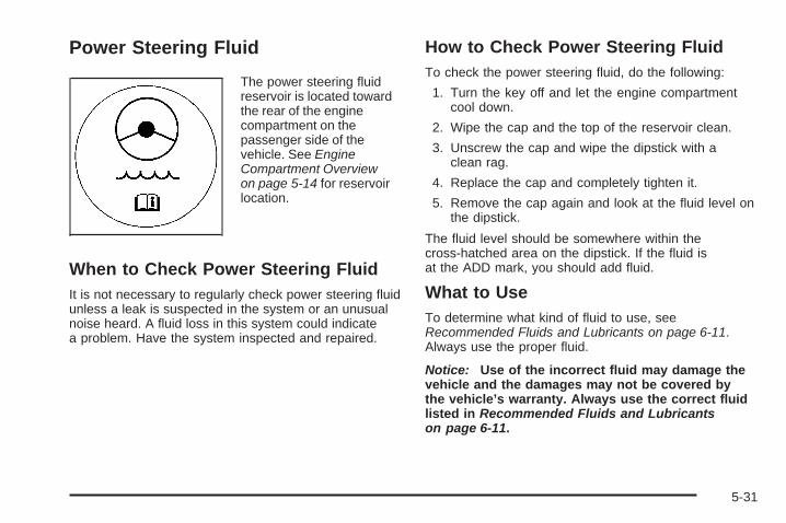
Power Steering Fluid
The power steering fluidreservoir is located towardthe rear of the enginecompartment on thepassenger side of thevehicle. See EngineCompartment Overviewon page 5-14 for reservoirlocation.
When to Check Power Steering FluidIt is not necessary to regularly check power steering fluidunless a leak is suspected in the system or an unusualnoise heard. A fluid loss in this system could indicatea problem. Have the system inspected and repaired.
How to Check Power Steering FluidTo check the power steering fluid, do the following:
1. Turn the key off and let the engine compartmentcool down.
2. Wipe the cap and the top of the reservoir clean.
3. Unscrew the cap and wipe the dipstick with aclean rag.
4. Replace the cap and completely tighten it.
5. Remove the cap again and look at the fluid level onthe dipstick.
The fluid level should be somewhere within thecross-hatched area on the dipstick. If the fluid isat the ADD mark, you should add fluid.
What to UseTo determine what kind of fluid to use, seeRecommended Fluids and Lubricants on page 6-11.Always use the proper fluid.
Notice: Use of the incorrect fluid may damage thevehicle and the damages may not be covered bythe vehicle’s warranty. Always use the correct fluidlisted in Recommended Fluids and Lubricantson page 6-11.
5-31
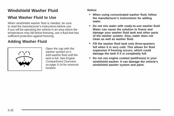
Windshield Washer Fluid
What Washer Fluid to UseWhen windshield washer fluid is needed, be sureto read the manufacturer’s instructions before use.If you will be operating the vehicle in an area where thetemperature may fall below freezing, use a fluid that hassufficient protection against freezing.
Adding Washer Fluid
Open the cap with thewasher symbol on it.Add washer fluid until thetank is full. See EngineCompartment Overviewon page 5-14 for reservoirlocation.
Notice:
• When using concentrated washer fluid, followthe manufacturer’s instructions for addingwater.
• Do not mix water with ready-to-use washer fluid.Water can cause the solution to freeze anddamage your washer fluid tank and other partsof the washer system. Also, water does notclean as well as washer fluid.
• Fill the washer fluid tank only three-quartersfull when it is very cold. This allows for fluidexpansion if freezing occurs, which coulddamage the tank if it is completely full.
• Do not use engine coolant (antifreeze) in yourwindshield washer. It can damage the vehicle’swindshield washer system and paint.
5-32
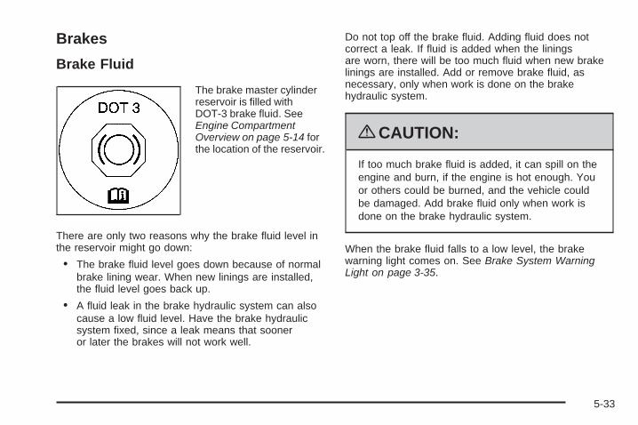
Brakes
Brake Fluid
The brake master cylinderreservoir is filled withDOT-3 brake fluid. SeeEngine CompartmentOverview on page 5-14 forthe location of the reservoir.
There are only two reasons why the brake fluid level inthe reservoir might go down:
• The brake fluid level goes down because of normalbrake lining wear. When new linings are installed,the fluid level goes back up.
• A fluid leak in the brake hydraulic system can alsocause a low fluid level. Have the brake hydraulicsystem fixed, since a leak means that sooneror later the brakes will not work well.
Do not top off the brake fluid. Adding fluid does notcorrect a leak. If fluid is added when the liningsare worn, there will be too much fluid when new brakelinings are installed. Add or remove brake fluid, asnecessary, only when work is done on the brakehydraulic system.
{CAUTION:
If too much brake fluid is added, it can spill on theengine and burn, if the engine is hot enough. Youor others could be burned, and the vehicle couldbe damaged. Add brake fluid only when work isdone on the brake hydraulic system.
When the brake fluid falls to a low level, the brakewarning light comes on. See Brake System WarningLight on page 3-35.
5-33
What to AddUse only new DOT-3 brake fluid from a sealedcontainer. See Recommended Fluids and Lubricants onpage 6-11.
Always clean the brake fluid reservoir cap and the areaaround the cap before removing it. This helps keepdirt from entering the reservoir.
{CAUTION:
With the wrong kind of fluid in the brake hydraulicsystem, the brakes might not work well. This couldcause a crash. Always use the proper brake fluid.
Notice:
• Using the wrong fluid can badly damage brakehydraulic system parts. For example, just afew drops of mineral-based oil, such as engineoil, in the brake hydraulic system can damagebrake hydraulic system parts so badly that theywill have to be replaced. Do not let someoneput in the wrong kind of fluid.
• If brake fluid is spilled on the vehicle’s paintedsurfaces, the paint finish can be damaged.Be careful not to spill brake fluid on the vehicle.If you do, wash it off immediately. See WashingYour Vehicle on page 5-93.
5-34
Brake WearThis vehicle has disc brakes. Disc brake pads havebuilt-in wear indicators that make a high-pitched warningsound when the brake pads are worn and new padsare needed. The sound can come and go or be heardall the time the vehicle is moving, except when applyingthe brake pedal firmly.
{CAUTION:
The brake wear warning sound means that soonthe brakes will not work well. That could lead to anaccident. When the brake wear warning sound isheard, have the vehicle serviced.
Notice: Continuing to drive with worn-out brakepads could result in costly brake repair.
Some driving conditions or climates can cause a brakesqueal when the brakes are first applied or lightly applied.This does not mean something is wrong with the brakes.
Properly torqued wheel nuts are necessary to helpprevent brake pulsation. When tires are rotated, inspectbrake pads for wear and evenly tighten wheel nutsin the proper sequence to torque specificationsin Capacities and Specifications on page 5-104.
Brake linings should always be replaced as completeaxle sets.
Brake Pedal TravelSee your dealer/retailer if the brake pedal does notreturn to normal height, or if there is a rapid increase inpedal travel. This could be a sign that brake servicemight be required.
Brake AdjustmentEvery time the brakes are applied, with or without thevehicle moving, the brakes adjust for wear.
5-35
Replacing Brake System PartsThe braking system on a vehicle is complex. Its manyparts have to be of top quality and work well together ifthe vehicle is to have really good braking. The vehiclewas designed and tested with top-quality brake parts.When parts of the braking system are replaced — forexample, when the brake linings wear down and newones are installed — be sure to get new approvedreplacement parts. If this is not done, the brakes mightnot work properly. For example, if someone puts inbrake linings that are wrong for the vehicle, the balancebetween the front and rear brakes can change — for theworse. The braking performance expected can change inmany other ways if the wrong replacement brake partsare installed.
BatteryThis vehicle has a maintenance free battery. When itis time for a new battery, see your dealer/retailer for onethat has the replacement number shown on the originalbattery’s label.For battery replacement, see your dealer/retailer or theservice manual. To purchase a service manual, seeService Publications Ordering Information on page 7-15.Warning: Battery posts, terminals, and relatedaccessories contain lead and lead compounds,chemicals known to the State of California to causecancer and reproductive harm. Wash hands afterhandling.
Vehicle Storage
{CAUTION:
Batteries have acid that can burn you and gas thatcan explode. You can be badly hurt if you are notcareful. See Jump Starting on page 5-37 for tipson working around a battery without getting hurt.
Infrequent Usage: If the vehicle is driven infrequently,remove the black, negative (−) cable from the battery.This helps keep the battery from running down.
Extended Storage: For extended storage of the vehicle,remove the black, negative (−) cable from the battery oruse a battery trickle charger. This helps maintain thecharge of the battery over an extended period of time.
5-36
Jump StartingIf the vehicle’s battery has run down, you may want touse another vehicle and some jumper cables to startthe vehicle. Be sure to use the following steps todo it safely.
On vehicles equipped with the optional power slidingdoor, a low-voltage battery or replacing a batterymay cause the system to become inoperative.See Power Sliding Door (PSD) on page 2-16for more information.
{CAUTION:
Batteries can hurt you. They can be dangerousbecause:
• They contain acid that can burn you.• They contain gas that can explode or ignite.• They contain enough electricity to burn you.
If you do not follow these steps exactly, some orall of these things can hurt you.
Notice: Ignoring these steps could result in costlydamage to your vehicle that would not be coveredby your warranty.
Trying to start your vehicle by pushing or pulling itwill not work, and it could damage your vehicle.
1. Check the other vehicle. It must have a 12-voltbattery with a negative ground system.
Notice: If the other vehicle’s system is not a 12-voltsystem with a negative ground, both vehicles canbe damaged. Only use vehicles with 12-volt systemswith negative grounds to jump start your vehicle.
2. Get the vehicles close enough so the jumper cablescan reach, but be sure the vehicles are not touchingeach other. If they are, it could cause a groundconnection that is not wanted. The vehicle wouldnot be able to be started, and the bad groundingcould damage the electrical systems.To avoid the possibility of the vehicles rolling, setthe parking brake firmly on both vehicles involvedin the jump start procedure. Put an automatictransaxle in P (PARK) or a manual transaxlein NEUTRAL before setting the parking brake.
5-37
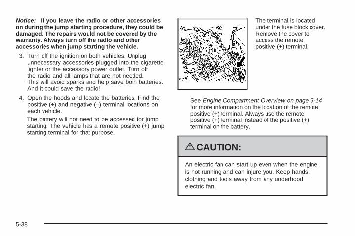
Notice: If you leave the radio or other accessorieson during the jump starting procedure, they could bedamaged. The repairs would not be covered by thewarranty. Always turn off the radio and otheraccessories when jump starting the vehicle.
3. Turn off the ignition on both vehicles. Unplugunnecessary accessories plugged into the cigarettelighter or the accessory power outlet. Turn offthe radio and all lamps that are not needed.This will avoid sparks and help save both batteries.And it could save the radio!
4. Open the hoods and locate the batteries. Find thepositive (+) and negative (−) terminal locations oneach vehicle.The battery will not need to be accessed for jumpstarting. The vehicle has a remote positive (+) jumpstarting terminal for that purpose.
The terminal is locatedunder the fuse block cover.Remove the cover toaccess the remotepositive (+) terminal.
See Engine Compartment Overview on page 5-14for more information on the location of the remotepositive (+) terminal. Always use the remotepositive (+) terminal instead of the positive (+)terminal on the battery.
{CAUTION:
An electric fan can start up even when the engineis not running and can injure you. Keep hands,clothing and tools away from any underhoodelectric fan.
5-38
{CAUTION:
Using a match near a battery can cause batterygas to explode. People have been hurt doing this,and some have been blinded. Use a flashlight ifyou need more light.
Be sure the battery has enough water. You do notneed to add water to the battery installed in yournew vehicle. But if a battery has filler caps, besure the right amount of fluid is there. If it is low,add water to take care of that first. If you do not,explosive gas could be present.
Battery fluid contains acid that can burn you.Do not get it on you. If you accidentally get it inyour eyes or on your skin, flush the place withwater and get medical help immediately.
{CAUTION:
Fans or other moving engine parts can injure youbadly. Keep your hands away from moving partsonce the engine is running.
5. Check that the jumper cables do not have looseor missing insulation. If they do, you could get ashock. The vehicles could be damaged too.Before the cables are connected, here are somebasic things you should know. Positive (+) will go topositive (+) or to a remote positive (+) terminal if thevehicle has one. Negative (−) will go to a heavy,unpainted metal engine part or to a remotenegative (−) terminal if the vehicle has one. Do notconnect positive (+) to negative (−) or you will get ashort that would damage the battery and maybeother parts too. Do not connect the negative (−) cableto the negative (−) terminal on the dead batterybecause this can cause sparks.
6. Connect the red positive (+) cable to the positive (+)terminal of the dead battery. Use a remotepositive (+) terminal if the vehicle has one.
5-39
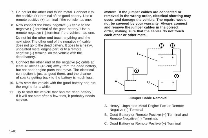
7. Do not let the other end touch metal. Connect it tothe positive (+) terminal of the good battery. Use aremote positive (+) terminal if the vehicle has one.
8. Now connect the black negative (−) cable to thenegative (−) terminal of the good battery. Use aremote negative (−) terminal if the vehicle has one.Do not let the other end touch anything until thenext step. The other end of the negative (−) cabledoes not go to the dead battery. It goes to a heavy,unpainted metal engine part, or to a remotenegative (−) terminal on the vehicle with thedead battery.
9. Connect the other end of the negative (−) cable atleast 18 inches (45 cm) away from the dead battery,but not near engine parts that move. The electricalconnection is just as good there, and the chanceof sparks getting back to the battery is much less.
10. Now start the vehicle with the good battery and runthe engine for a while.
11. Try to start the vehicle that had the dead battery.If it will not start after a few tries, it probably needsservice.
Notice: If the jumper cables are connected orremoved in the wrong order, electrical shorting mayoccur and damage the vehicle. The repairs wouldnot be covered by your warranty. Always connectand remove the jumper cables in the correctorder, making sure that the cables do not toucheach other or other metal.
A. Heavy, Unpainted Metal Engine Part or RemoteNegative (−) Terminal
B. Good Battery or Remote Positive (+) Terminal andRemote Negative (−) Terminals
C. Dead Battery or Remote Positive (+) Terminal
Jumper Cable Removal
5-40
To disconnect the jumper cables from both vehicles, dothe following:
1. Disconnect the black negative (−) cable from thevehicle that had the dead battery.
2. Disconnect the black negative (−) cable from thevehicle with the good battery.
3. Disconnect the red positive (+) cable from thevehicle with the good battery.
4. Disconnect the red positive (+) cable from the othervehicle.
5. Return the remote positive (+) terminal cover orunderhood fuse block cover to its original position.
Headlamp AimingHeadlamp aim has been preset at the factory andshould need no further adjustment.
However, if your vehicle is damaged in a crash, theheadlamp aim may be affected. Aim adjustment to thelow-beam headlamps may be necessary if oncomingdrivers flash their high-beam headlamps at you(for vertical aim).
If the headlamps need to be re-aimed, it isrecommended that you take the vehicle to yourdealer/retailer for service.
Bulb ReplacementFor the proper type of replacement bulbs, seeReplacement Bulbs on page 5-45.
For any bulb changing procedure not listed in thissection, contact your dealer/retailer.
Halogen Bulbs
{CAUTION:
Halogen bulbs have pressurized gas inside andcan burst if you drop or scratch the bulb. You orothers could be injured. Be sure to read and followthe instructions on the bulb package.
5-41

Headlamps and Sidemarker Lamps
A. High-beam HeadlampB. Low-beam HeadlampC. Sidemarker Lamp
To replace one of these bulbs:
1. Open the hood. See Hood Release on page 5-13.
2. Remove the headlamp retainer pin (A) by turning ittowards the headlamp assembly and pulling itstraight out.
5-42
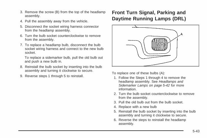
3. Remove the screw (B) from the top of the headlampassembly.
4. Pull the assembly away from the vehicle.
5. Disconnect the socket wiring harness connectorfrom the headlamp assembly.
6. Turn the bulb socket counterclockwise to removefrom the assembly.
7. To replace a headlamp bulb, disconnect the bulbsocket wiring harness and connect to the new bulbsocket.To replace a sidemarker bulb, pull the old bulb outand push a new bulb in.
8. Reinstall the bulb socket by inserting into the bulbassembly and turning it clockwise to secure.
9. Reverse steps 1 through 5 to reinstall.
Front Turn Signal, Parking andDaytime Running Lamps (DRL)
To replace one of these bulbs (A):1. Follow the Steps 1 through 4 to remove the
headlamp assembly. See Headlamps andSidemarker Lamps on page 5-42 for moreinformation.
2. Turn the bulb socket counterclockwise to removefrom the assembly.
3. Pull the old bulb out from the bulb socket.4. Replace with a new bulb5. Reinstall the bulb socket by inserting into the bulb
assembly and turning it clockwise to secure.6. Reverse the steps to reinstall the headlamp
assembly.
5-43
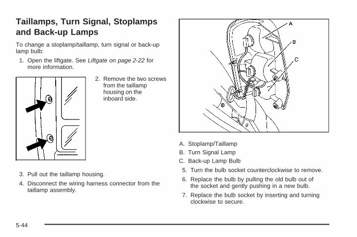
Taillamps, Turn Signal, Stoplampsand Back-up LampsTo change a stoplamp/taillamp, turn signal or back-uplamp bulb:
1. Open the liftgate. See Liftgate on page 2-22 formore information.
2. Remove the two screwsfrom the taillamphousing on theinboard side.
3. Pull out the taillamp housing.
4. Disconnect the wiring harness connector from thetaillamp assembly.
A. Stoplamp/TaillampB. Turn Signal LampC. Back-up Lamp Bulb
5. Turn the bulb socket counterclockwise to remove.
6. Replace the bulb by pulling the old bulb out ofthe socket and gently pushing in a new bulb.
7. Replace the bulb socket by inserting and turningclockwise to secure.
5-44
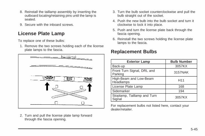
8. Reinstall the taillamp assembly by inserting theoutboard locating/retaining pins until the lamp isseated.
9. Secure with the inboard screws.
License Plate LampTo replace one of these bulbs:
1. Remove the two screws holding each of the licenseplate lamps to the fascia.
2. Turn and pull the license plate lamp forwardthrough the fascia opening.
3. Turn the bulb socket counterclockwise and pull thebulb straight out of the socket.
4. Push the new bulb into the bulb socket and turn itclockwise to lock it into place.
5. Push and turn the license plate back through thefascia opening.
6. Reinstall the two screws holding the license platelamps to the fascia.
Replacement Bulbs
Exterior Lamp Bulb NumberBack-up 3057KXFront Turn Signal, DRL andParking 3157NAK
High-Beam and Low-BeamHeadlamps H11
License Plate Lamp 168Sidemarker 194Stoplamp, Taillamp and TurnSignal 3057KX
For replacement bulbs not listed here, contact yourdealer/retailer.
5-45
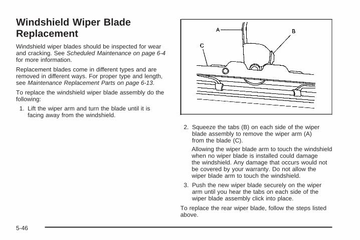
Windshield Wiper BladeReplacementWindshield wiper blades should be inspected for wearand cracking. See Scheduled Maintenance on page 6-4for more information.
Replacement blades come in different types and areremoved in different ways. For proper type and length,see Maintenance Replacement Parts on page 6-13.
To replace the windshield wiper blade assembly do thefollowing:
1. Lift the wiper arm and turn the blade until it isfacing away from the windshield.
2. Squeeze the tabs (B) on each side of the wiperblade assembly to remove the wiper arm (A)from the blade (C).Allowing the wiper blade arm to touch the windshieldwhen no wiper blade is installed could damagethe windshield. Any damage that occurs would notbe covered by your warranty. Do not allow thewiper blade arm to touch the windshield.
3. Push the new wiper blade securely on the wiperarm until you hear the tabs on each side of thewiper blade assembly click into place.
To replace the rear wiper blade, follow the steps listedabove.
5-46
TiresYour new vehicle comes with high-quality tiresmade by a leading tire manufacturer. If you everhave questions about your tire warranty and whereto obtain service, see your vehicle Warrantybooklet for details.
{CAUTION:
• Poorly maintained and improperly usedtires are dangerous.
• Overloading your tires can causeoverheating as a result of too muchflexing. You could have an air-out anda serious accident. See Loading theVehicle on page 4-19.
CAUTION: (Continued)
CAUTION: (Continued)
• Underinflated tires pose the same dangeras overloaded tires. The resulting accidentcould cause serious injury. Check all tiresfrequently to maintain the recommendedpressure. Tire pressure should bechecked when your tires are cold. SeeInflation - Tire Pressure on page 5-54.
• Overinflated tires are more likely to becut, punctured, or broken by a suddenimpact — such as when you hit a pothole.Keep tires at the recommended pressure.
• Worn, old tires can cause accidents.If your tread is badly worn, or if your tireshave been damaged, replace them.
See High-Speed Operation on page 5-56 forinflation pressure adjustment for high speeddriving.
5-47
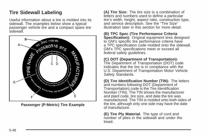
Tire Sidewall LabelingUseful information about a tire is molded into itssidewall. The examples below show a typicalpassenger vehicle tire and a compact spare tiresidewall.
(A) Tire Size: The tire size is a combination ofletters and numbers used to define a particulartire’s width, height, aspect ratio, construction type,and service description. See the “Tire Size”illustration later in this section for more detail.
(B) TPC Spec (Tire Performance CriteriaSpecification): Original equipment tires designedto GM’s specific tire performance criteria havea TPC specification code molded onto the sidewall.GM’s TPC specifications meet or exceed allfederal safety guidelines.
(C) DOT (Department of Transportation):The Department of Transportation (DOT) codeindicates that the tire is in compliance with theU.S. Department of Transportation Motor VehicleSafety Standards.
(D) Tire Identification Number (TIN): The lettersand numbers following DOT (Department ofTransportation) code is the Tire IdentificationNumber (TIN). The TIN shows the manufacturerand plant code, tire size, and date the tire wasmanufactured. The TIN is molded onto both sides ofthe tire, although only one side may have the dateof manufacture.
(E) Tire Ply Material: The type of cord andnumber of plies in the sidewall and under thetread.
Passenger (P-Metric) Tire Example
5-48
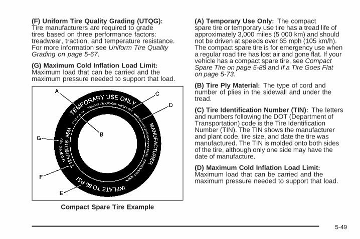
(F) Uniform Tire Quality Grading (UTQG):Tire manufacturers are required to gradetires based on three performance factors:treadwear, traction, and temperature resistance.For more information see Uniform Tire QualityGrading on page 5-67.
(G) Maximum Cold Inflation Load Limit:Maximum load that can be carried and themaximum pressure needed to support that load.
(A) Temporary Use Only: The compactspare tire or temporary use tire has a tread life ofapproximately 3,000 miles (5 000 km) and shouldnot be driven at speeds over 65 mph (105 km/h).The compact spare tire is for emergency use whena regular road tire has lost air and gone flat. If yourvehicle has a compact spare tire, see CompactSpare Tire on page 5-88 and If a Tire Goes Flaton page 5-73.
(B) Tire Ply Material: The type of cord andnumber of plies in the sidewall and under thetread.
(C) Tire Identification Number (TIN): The lettersand numbers following the DOT (Department ofTransportation) code is the Tire IdentificationNumber (TIN). The TIN shows the manufacturerand plant code, tire size, and date the tire wasmanufactured. The TIN is molded onto both sidesof the tire, although only one side may have thedate of manufacture.
(D) Maximum Cold Inflation Load Limit:Maximum load that can be carried and themaximum pressure needed to support that load.
Compact Spare Tire Example
5-49
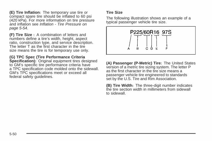
(E) Tire Inflation: The temporary use tire orcompact spare tire should be inflated to 60 psi(420 kPa). For more information on tire pressureand inflation see Inflation - Tire Pressure onpage 5-54.
(F) Tire Size : A combination of letters andnumbers define a tire’s width, height, aspectratio, construction type, and service description.The letter T as the first character in the tiresize means the tire is for temporary use only.
(G) TPC Spec (Tire Performance CriteriaSpecification): Original equipment tires designedto GM’s specific tire performance criteria havea TPC specification code molded onto the sidewall.GM’s TPC specifications meet or exceed allfederal safety guidelines.
Tire SizeThe following illustration shows an example of atypical passenger vehicle tire size.
(A) Passenger (P-Metric) Tire: The United Statesversion of a metric tire sizing system. The letter Pas the first character in the tire size means apassenger vehicle tire engineered to standardsset by the U.S. Tire and Rim Association.
(B) Tire Width: The three-digit number indicatesthe tire section width in millimeters from sidewallto sidewall.
5-50
(C) Aspect Ratio: A two-digit number thatindicates the tire height-to-width measurements.For example, if the tire size aspect ratio is 60, asshown in item C of the illustration, it would meanthat the tire’s sidewall is 60 percent as high as itis wide.
(D) Construction Code: A letter code is used toindicate the type of ply construction in the tire. Theletter R means radial ply construction; the letter Dmeans diagonal or bias ply construction; and theletter B means belted-bias ply construction.
(E) Rim Diameter: Diameter of the wheel ininches.
(F) Service Description: These charactersrepresent the load range and speed rating of thetire. The load index represents the load carrycapacity a tire is certified to carry. The load indexcan range from 1 to 279. The speed rating isthe maximum speed a tire is certified to carrya load. Speed ratings range from A to Z.
Tire Terminology and Definitions
Air Pressure: The amount of air inside thetire pressing outward on each square inch of thetire. Air pressure is expressed in pounds persquare inch (psi) or kilopascal (kPa).
Accessory Weight: This means the combinedweight of optional accessories. Some examples ofoptional accessories are, automatic transmission,power steering, power brakes, power windows,power seats, and air conditioning.
Aspect Ratio: The relationship of a tire’s heightto its width.
Belt: A rubber coated layer of cords that islocated between the plies and the tread. Cordsmay be made from steel or other reinforcingmaterials.
Bead: The tire bead contains steel wires wrappedby steel cords that hold the tire onto the rim.
Bias Ply Tire: A pneumatic tire in which the pliesare laid at alternate angles less than 90 degreesto the centerline of the tread.
5-51
Cold Tire Pressure: The amount of air pressurein a tire, measured in pounds per square inch (psi)or kilopascals (kPa) before a tire has built up heatfrom driving. See Inflation - Tire Pressure onpage 5-54.
Curb Weight: The weight of a motor vehicle withstandard and optional equipment including themaximum capacity of fuel, oil, and coolant,but without passengers and cargo.
DOT Markings: A code molded into the sidewallof a tire signifying that the tire is in compliancewith the U.S. Department of Transportation (DOT)motor vehicle safety standards. The DOT codeincludes the Tire Identification Number (TIN), analphanumeric designator which can also identify thetire manufacturer, production plant, brand, and dateof production.
GVWR: Gross Vehicle Weight Rating.See Loading the Vehicle on page 4-19.
GAWR FRT: Gross Axle Weight Rating for thefront axle. See Loading the Vehicle on page 4-19.
GAWR RR: Gross Axle Weight Rating for therear axle. See Loading the Vehicle on page 4-19.
Intended Outboard Sidewall: The side of anasymmetrical tire, that must always face outwardwhen mounted on a vehicle.
Kilopascal (kPa): The metric unit for air pressure.
Light Truck (LT-Metric) Tire: A tire used onlight duty trucks and some multipurpose passengervehicles.
Load Index: An assigned number ranging from1 to 279 that corresponds to the load carryingcapacity of a tire.
Maximum Inflation Pressure: The maximumair pressure to which a cold tire can be inflated.The maximum air pressure is molded onto thesidewall.
Maximum Load Rating: The load rating for a tireat the maximum permissible inflation pressurefor that tire.
Maximum Loaded Vehicle Weight: The sum ofcurb weight, accessory weight, vehicle capacityweight, and production options weight.
Normal Occupant Weight: The number ofoccupants a vehicle is designed to seat multipliedby 150 lbs (68 kg). See Loading the Vehicle onpage 4-19.
Occupant Distribution: Designated seatingpositions.
5-52
Outward Facing Sidewall: The side of anasymmetrical tire that has a particular side thatfaces outward when mounted on a vehicle.The side of the tire that contains a whitewall,bears white lettering, or bears manufacturer,brand, and/or model name molding that is higheror deeper than the same moldings on the othersidewall of the tire.
Passenger (P-Metric) Tire: A tire used onpassenger cars and some light duty trucks andmultipurpose vehicles.
Recommended Inflation Pressure: Vehiclemanufacturer’s recommended tire inflationpressure as shown on the tire placard.See Inflation - Tire Pressure on page 5-54and Loading the Vehicle on page 4-19.
Radial Ply Tire: A pneumatic tire in which theply cords that extend to the beads are laid at90 degrees to the centerline of the tread.
Rim: A metal support for a tire and upon whichthe tire beads are seated.
Sidewall: The portion of a tire between the treadand the bead.
Speed Rating: An alphanumeric code assigned toa tire indicating the maximum speed at which atire can operate.
Traction: The friction between the tire and theroad surface. The amount of grip provided.
Tread: The portion of a tire that comes intocontact with the road.
Treadwear Indicators: Narrow bands, sometimescalled wear bars, that show across the tread ofa tire when only 1/16 inch (1.6 mm) of treadremains. See When It Is Time for New Tireson page 5-63.
UTQGS (Uniform Tire Quality GradingStandards): A tire information system thatprovides consumers with ratings for a tire’straction, temperature, and treadwear. Ratings aredetermined by tire manufacturers using governmenttesting procedures. The ratings are molded intothe sidewall of the tire. See Uniform Tire QualityGrading on page 5-67.
Vehicle Capacity Weight: The number ofdesignated seating positions multiplied by 150 lbs(68 kg) plus the rated cargo load. See Loadingthe Vehicle on page 4-19.
Vehicle Maximum Load on the Tire: Load onan individual tire due to curb weight, accessoryweight, occupant weight, and cargo weight.
5-53
Vehicle Placard: A label permanently attachedto a vehicle showing the vehicle’s capacityweight and the original equipment tire sizeand recommended inflation pressure.See “Tire and Loading Information Label”under Loading the Vehicle on page 4-19.
Inflation - Tire PressureTires need the correct amount of air pressure tooperate effectively.
Notice: Do not let anyone tell you thatunder-inflation or over-inflation is all right.It is not. If your tires do not have enough air(under-inflation), you can get the following:• Too much flexing• Too much heat• Tire overloading• Premature or irregular wear• Poor handling• Reduced fuel economy
If your tires have too much air (over-inflation),you can get the following:• Unusual wear• Poor handling• Rough ride• Needless damage from road hazards
A vehicle specific Tire and Loading Informationlabel is attached to your vehicle. This label showsyour vehicle’s original equipment tires and thecorrect inflation pressures for your tires when theyare cold. The recommended cold tire inflationpressure, shown on the label, is the minimumamount of air pressure needed to support yourvehicle’s maximum load carrying capacity.
For additional information regarding how muchweight your vehicle can carry, and an example ofthe Tire and Loading Information label, see Loadingthe Vehicle on page 4-19. How you load yourvehicle affects vehicle handling and ride comfort.Never load your vehicle with more weight than itwas designed to carry.
5-54
When to CheckCheck your tires once a month or more. Do notforget to check the compact spare tire, it shouldbe at 60 psi (420 kPa). For additional informationregarding the compact spare tire, see CompactSpare Tire on page 5-88.
How to CheckUse a good quality pocket-type gage to check tirepressure. You cannot tell if your tires are properlyinflated simply by looking at them. Radial tiresmay look properly inflated even when they areunder-inflated. Check the tire’s inflation pressurewhen the tires are cold. Cold means your vehiclehas been sitting for at least three hours or drivenno more than 1 mile (1.6 km).
Remove the valve cap from the tire valve stem.Press the tire gage firmly onto the valve toget a pressure measurement. If the cold tireinflation pressure matches the recommendedpressure on the Tire and Loading Informationlabel, no further adjustment is necessary. If theinflation pressure is low, add air until you reachthe recommended amount.
If you overfill the tire, release air by pushing onthe metal stem in the center of the tire valve.Re-check the tire pressure with the tire gage.
Be sure to put the valve caps back on the valvestems. They help prevent leaks by keeping out dirtand moisture.
5-55
High-Speed Operation
{CAUTION:
Driving at high speeds, 100 mph (160 km/h) orhigher, puts an additional strain on tires. Sustainedhigh-speed driving causes excessive heat build upand can cause sudden tire failure. You could havea crash and you or others could be killed. Somehigh-speed rated tires require inflation pressureadjustment for high speed operation. When speedlimits and road conditions are such that a vehiclecan be driven at high speeds, make sure the tiresare rated for high speed operation, in excellentcondition, and set to the correct cold tire inflationpressure for the vehicle load.
If your vehicle has P225/60R17 size tires, they willrequire inflation pressure adjustment when driving yourvehicle at speeds of 100 mph (160 km/h) or higher.Set the cold inflation pressure to the maximum inflationpressure shown on the tire sidewall, or 38 psi (262 kPa),whichever is lower. See the example following. Whenyou end this high-speed driving, return the tires to thecold tire inflation pressure shown on the Tire and LoadingInformation label. See Loading the Vehicle on page 4-19and Inflation - Tire Pressure on page 5-54.
Example:
You will find the maximum load and inflation pressuremolded on the tire’s sidewall, in small letters, nearthe rim flange. It will read something like this: Maximumload 690 kg (1521 lbs) 300 kPa (44 psi) Max. Press.
For this example, you would set the inflation pressure forhigh-speed driving at 38 psi (262 kPa).
5-56
Tire Pressure Monitor SystemThe Tire Pressure Monitor System (TPMS) uses radioand sensor technology to check tire pressure levels.The TPMS sensors monitor the air pressure inyour vehicle’s tires and transmit tire pressure readingsto a receiver located in the vehicle.
Each tire, including the spare (if provided), should bechecked monthly when cold and inflated to the inflationpressure recommended by the vehicle manufactureron the vehicle placard or tire inflation pressure label.(If your vehicle has tires of a different size than thesize indicated on the vehicle placard or tire inflationpressure label, you should determine the propertire inflation pressure for those tires.)
As an added safety feature, your vehicle has beenequipped with a tire pressure monitoring system (TPMS)that illuminates a low tire pressure telltale when oneor more of your tires is significantly under-inflated.
Accordingly, when the low tire pressure telltaleilluminates, you should stop and check your tires assoon as possible, and inflate them to the properpressure. Driving on a significantly under-inflated tirecauses the tire to overheat and can lead to tire failure.Under-inflation also reduces fuel efficiency and tiretread life, and may affect the vehicle’s handlingand stopping ability.
Please note that the TPMS is not a substitute for propertire maintenance, and it is the driver’s responsibility tomaintain correct tire pressure, even if under-inflationhas not reached the level to trigger illumination ofthe TPMS low tire pressure telltale.
Your vehicle has also been equipped with a TPMSmalfunction indicator to indicate when the system isnot operating properly. The TPMS malfunction indicatoris combined with the low tire pressure telltale. When thesystem detects a malfunction, the telltale will flash forapproximately one minute and then remain continuouslyilluminated. This sequence will continue uponsubsequent vehicle start-ups as long as the malfunctionexists.
When the malfunction indicator is illuminated, thesystem may not be able to detect or signal low tirepressure as intended. TPMS malfunctions may occurfor a variety of reasons, including the installation ofreplacement or alternate tires or wheels on the vehiclethat prevent the TPMS from functioning properly. Alwayscheck the TPMS malfunction telltale after replacing oneor more tires or wheels on your vehicle to ensure that thereplacement or alternate tires and wheels allow theTPMS to continue to function properly.
See Tire Pressure Monitor Operation on page 5-58 foradditional information.
5-57
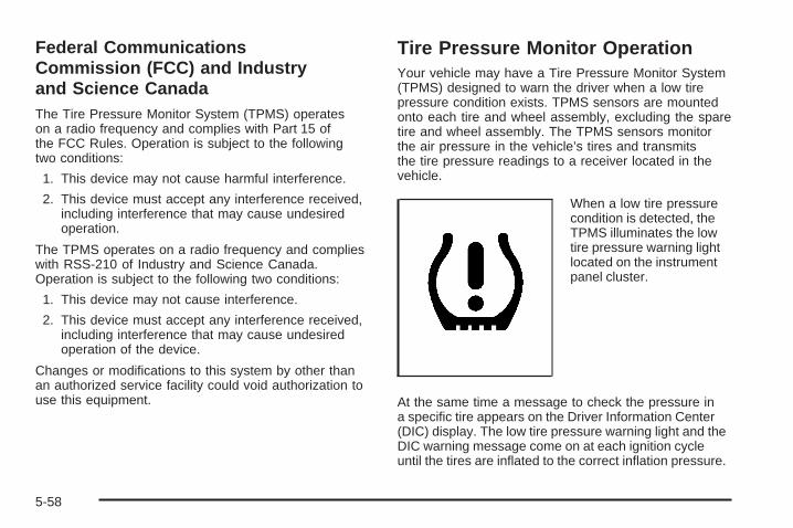
Federal CommunicationsCommission (FCC) and Industryand Science CanadaThe Tire Pressure Monitor System (TPMS) operateson a radio frequency and complies with Part 15 ofthe FCC Rules. Operation is subject to the followingtwo conditions:
1. This device may not cause harmful interference.
2. This device must accept any interference received,including interference that may cause undesiredoperation.
The TPMS operates on a radio frequency and complieswith RSS-210 of Industry and Science Canada.Operation is subject to the following two conditions:
1. This device may not cause interference.
2. This device must accept any interference received,including interference that may cause undesiredoperation of the device.
Changes or modifications to this system by other thanan authorized service facility could void authorization touse this equipment.
Tire Pressure Monitor OperationYour vehicle may have a Tire Pressure Monitor System(TPMS) designed to warn the driver when a low tirepressure condition exists. TPMS sensors are mountedonto each tire and wheel assembly, excluding the sparetire and wheel assembly. The TPMS sensors monitorthe air pressure in the vehicle’s tires and transmitsthe tire pressure readings to a receiver located in thevehicle.
When a low tire pressurecondition is detected, theTPMS illuminates the lowtire pressure warning lightlocated on the instrumentpanel cluster.
At the same time a message to check the pressure ina specific tire appears on the Driver Information Center(DIC) display. The low tire pressure warning light and theDIC warning message come on at each ignition cycleuntil the tires are inflated to the correct inflation pressure.
5-58
Using the DIC, tire pressure levels can be viewed by thedriver. For additional information and details about theDIC operation and displays see DIC Operation andDisplays on page 3-44 and DIC Warnings and Messageson page 3-51.
The low tire pressure warning light may come on incool weather when the vehicle is first started, and thenturn off as you start to drive. This could be an earlyindicator that the air pressure in the tire(s) are gettinglow and need to be inflated to the proper pressure.
A Tire and Loading Information label, attached toyour vehicle, shows the size of your vehicle’s originalequipment tires and the correct inflation pressure foryour vehicle’s tires when they are cold. See Loading theVehicle on page 4-19, for an example of the Tire andLoading Information label and its location on your vehicle.Also see Inflation - Tire Pressure on page 5-54.
Your vehicle’s TPMS can warn you about a low tirepressure condition but it does not replace normaltire maintenance. See Tire Inspection and Rotationon page 5-62 and Tires on page 5-47.
Notice: Liquid tire sealants could damage the TirePressure Monitor System (TPMS) sensors. Sensordamage caused by using a tire sealant is notcovered by your warranty. Do not use liquid tiresealants.
TPMS Malfunction Light and MessageThe TPMS will not function properly if one or more ofthe TPMS sensors are missing or inoperable. When thesystem detects a malfunction, the low tire warning lightflashes for about one minute and then stays on for theremainder of the ignition cycle. A DIC warning messageis also displayed. The low tire warning light and DICwarning message come on at each ignition cycle until theproblem is corrected. Some of the conditions that cancause the malfunction light and DIC message to comeon are:
• One of the road tires has been replaced with thespare tire. The spare tire does not have a TPMSsensor. The TPMS malfunction light and DICmessage should go off once you re-install theroad tire containing the TPMS sensor.
• The TPMS sensor matching process was started butnot completed or not completed successfully afterrotating the vehicle’s tires. The DIC message andTPMS malfunction light should go off once the TPMSsensor matching process is performed successfully.See “TPMS Sensor Matching Process” later in thissection.
5-59
• One or more TPMS sensors are missing ordamaged. The DIC message and the TPMSmalfunction light should go off when the TPMSsensors are installed and the sensor matchingprocess is performed successfully. See your dealer/retailer for service.
• Replacement tires or wheels do not match yourvehicle’s original equipment tires or wheels. Tiresand wheels other than those recommended for yourvehicle could prevent the TPMS from functioningproperly. See Buying New Tires on page 5-64.
• Operating electronic devices or being near facilitiesusing radio wave frequencies similar to the TPMScould cause the TPMS sensors to malfunction.
If the TPMS is not functioning it cannot detect orsignal a low tire condition. See your dealer/retailer forservice if the TPMS malfunction light and DIC messagecomes on and stays on.
TPMS Sensor Matching ProcessEach TPMS sensor has a unique identification code. Anytime you rotate your vehicle’s tires or replace one or moreof the TPMS sensors, the identification codes will need tobe matched to the new tire/wheel position. The sensorsare matched to the tire/wheel positions in the followingorder: driver side front tire, passenger side front tire,passenger side rear tire, and driver side rear tire usinga TPMS diagnostic tool. See your dealer/retailer forservice.
The TPMS sensors can also be matched to eachtire/wheel position by increasing or decreasing thetire’s air pressure. If increasing the tire’s air pressure,do not exceed the maximum inflation pressure indicatedon the tire’s sidewall.
To decrease air-pressure out of a tire you can use thepointed end of the valve cap, a pencil-style air pressuregage, or a key.
5-60
You will have two minutes to match the first tire/wheelposition, and five minutes overall to match all fourtire/wheel positions. If it takes longer than two minutes, tomatch the first tire and wheel, or more than five minutesto match all four tire and wheel positions the matchingprocess stops and you will need to start over.
The TPMS sensor matching process is outlined below:
1. Set the parking brake.
2. Turn the ignition switch to RUN with the engine off.
3. Using the Remote Keyless Entry (RKE) transmitter,lock and unlock the vehicle’s doors.
4. Press and hold the RKE transmitter’s LOCK andUNLOCK buttons at the same time, for aboutthree seconds. The horn chirps two times indicatingthe receiver is ready for the sensor matchingprocess to begin.
5. Start with the driver side front tire. The driver sideturn signal lamp comes on.
6. Remove the valve cap from the valve cap stem.Activate the TPMS sensor by increasing ordecreasing the tire’s air pressure for five seconds,or until a horn chirp sounds. The horn chirp,which may take up to 30 seconds to sound,confirms that the sensor identification code hasbeen matched to this tire and wheel position.
7. Proceed to the passenger side front tire, and repeatthe procedure in Step 6.
8. Proceed to the passenger side rear tire, and repeatthe procedure in Step 6.
9. Proceed to the driver side rear tire, and repeat theprocedure in Step 6.
10. After hearing the confirming horn chirp for the driverside rear tire, the tire sensor matching processends. Turn the ignition switch to LOCK.
11. Set all four tires to the recommended air pressurelevel as indicated on the Tire and LoadingInformation label.
12. Put the valve caps back on the valve stems.
5-61
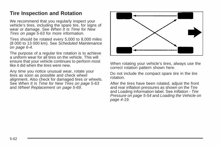
Tire Inspection and RotationWe recommend that you regularly inspect yourvehicle’s tires, including the spare tire, for signs ofwear or damage. See When It Is Time for NewTires on page 5-63 for more information.
Tires should be rotated every 5,000 to 8,000 miles(8 000 to 13 000 km). See Scheduled Maintenanceon page 6-4.
The purpose of a regular tire rotation is to achievea uniform wear for all tires on the vehicle. This willensure that your vehicle continues to perform mostlike it did when the tires were new.
Any time you notice unusual wear, rotate yourtires as soon as possible and check wheelalignment. Also check for damaged tires or wheels.See When It Is Time for New Tires on page 5-63and Wheel Replacement on page 5-69.
When rotating your vehicle’s tires, always use thecorrect rotation pattern shown here.
Do not include the compact spare tire in the tirerotation.
After the tires have been rotated, adjust the frontand rear inflation pressures as shown on the Tireand Loading Information label. See Inflation - TirePressure on page 5-54 and Loading the Vehicle onpage 4-19.
5-62
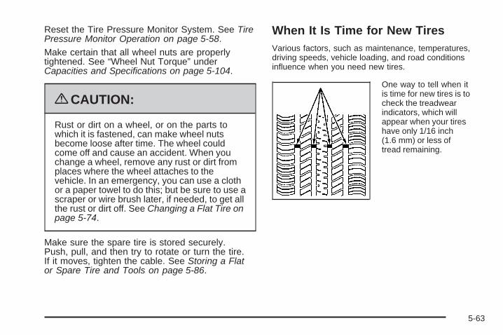
Reset the Tire Pressure Monitor System. See TirePressure Monitor Operation on page 5-58.
Make certain that all wheel nuts are properlytightened. See “Wheel Nut Torque” underCapacities and Specifications on page 5-104.
{CAUTION:
Rust or dirt on a wheel, or on the parts towhich it is fastened, can make wheel nutsbecome loose after time. The wheel couldcome off and cause an accident. When youchange a wheel, remove any rust or dirt fromplaces where the wheel attaches to thevehicle. In an emergency, you can use a clothor a paper towel to do this; but be sure to use ascraper or wire brush later, if needed, to get allthe rust or dirt off. See Changing a Flat Tire onpage 5-74.
Make sure the spare tire is stored securely.Push, pull, and then try to rotate or turn the tire.If it moves, tighten the cable. See Storing a Flator Spare Tire and Tools on page 5-86.
When It Is Time for New TiresVarious factors, such as maintenance, temperatures,driving speeds, vehicle loading, and road conditionsinfluence when you need new tires.
One way to tell when itis time for new tires is tocheck the treadwearindicators, which willappear when your tireshave only 1/16 inch(1.6 mm) or less oftread remaining.
5-63
You need new tires if any of the following statementsare true:
• You can see the indicators at three or more placesaround the tire.
• You can see cord or fabric showing through thetire’s rubber.
• The tread or sidewall is cracked, cut, or snaggeddeep enough to show cord or fabric.
• The tire has a bump, bulge, or split.
• The tire has a puncture, cut, or other damage thatcannot be repaired well because of the size orlocation of the damage.
The rubber in tires degrades over time, even if they arenot being used. This is also true for the spare tire, ifyour vehicle has one. Multiple conditions affect how fastthis aging takes place, including temperatures, loadingconditions, and inflation pressure maintenance. Withproper care and maintenance tires will typically wearout before they degrade due to age. If you are unsureabout the need to replace your tires as they getolder, consult the tire manufacturer for more information.
Buying New TiresGM has developed and matched specific tires foryour vehicle. The original equipment tires installedon your vehicle, when it was new, were designedto meet General Motors Tire Performance CriteriaSpecification (TPC Spec) system rating. If you needreplacement tires, GM strongly recommends thatyou get tires with the same TPC Spec rating. Thisway, your vehicle will continue to have tires that aredesigned to give the same performance and vehiclesafety, during normal use, as the original tires.
GM’s exclusive TPC Spec system considersover a dozen critical specifications that impact theoverall performance of your vehicle, including brakesystem performance, ride and handling, tractioncontrol, and tire pressure monitoring performance.GM’s TPC Spec number is molded onto the tire’ssidewall near the tire size. If the tires have anall-season tread design, the TPC Spec numberwill be followed by an MS for mud and snow. SeeTire Sidewall Labeling on page 5-48 for additionalinformation.
5-64
GM recommends replacing tires in sets of four.This is because uniform tread depth on all tireswill help keep your vehicle performing most likeit did when the tires were new. Replacing lessthan a full set of tires can affect the brakingand handling performance of your vehicle.See Tire Inspection and Rotation on page 5-62for information on proper tire rotation.
{CAUTION:
Mixing tires could cause you to lose controlwhile driving. If you mix tires of differentsizes, brands, or types (radial and bias-beltedtires), the vehicle may not handle properly,and you could have a crash. Using tires ofdifferent sizes, brands, or types may alsocause damage to your vehicle. Be sure touse the correct size, brand, and type oftires on all wheels. It is all right to drivewith your compact spare temporarily, asit was developed for use on your vehicle.See Compact Spare Tire on page 5-88.
{CAUTION:
If you use bias-ply tires on the vehicle, thewheel rim flanges could develop cracks aftermany miles of driving. A tire and/or wheelcould fail suddenly, causing a crash. Useonly radial-ply tires with the wheels on thevehicle.
If you must replace your vehicle’s tires with thosethat do not have a TPC Spec number, makesure they are the same size, load range, speedrating, and construction type (radial andbias-belted tires) as your vehicle’s original tires.
Vehicles that have a tire pressure monitoringsystem could give an inaccurate low-pressurewarning if non-TPC Spec rated tires are installedon your vehicle. Non-TPC Spec rated tiresmay give a low-pressure warning that is higheror lower than the proper warning level you wouldget with TPC Spec rated tires. See Tire PressureMonitor System on page 5-57.
5-65
Your vehicle’s original equipment tires are listedon the Tire and Loading Information Label.See Loading the Vehicle on page 4-19, for moreinformation about the Tire and Loading InformationLabel and its location on your vehicle.
Different Size Tires and WheelsIf you add wheels or tires that are a different size thanyour original equipment wheels and tires, this may affectthe way your vehicle performs, including its braking, rideand handling characteristics, stability, and resistanceto rollover. Additionally, if your vehicle has electronicsystems such as, antilock brakes, traction control, andelectronic stability control, the performance of thesesystems can be affected.
{CAUTION:
If you add different sized wheels, your vehicle maynot provide an acceptable level of performance andsafety if tires not recommended for those wheelsare selected. You may increase the chance that youwill crash and suffer serious injury. Only use GMspecific wheel and tire systems developed for yourvehicle, and have them properly installed by a GMcertified technician.
See Buying New Tires on page 5-64 and Accessoriesand Modifications on page 5-3 for additional information.
5-66

Uniform Tire Quality GradingQuality grades can be found where applicableon the tire sidewall between tread shoulderand maximum section width. For example:
Treadwear 200 Traction AATemperature AThe following information relates to the systemdeveloped by the United States National HighwayTraffic Safety Administration (NHTSA), whichgrades tires by treadwear, traction, andtemperature performance. This applies only tovehicles sold in the United States. The grades aremolded on the sidewalls of most passenger cartires. The Uniform Tire Quality Grading (UTQG)system does not apply to deep tread, winter-typesnow tires, space-saver, or temporary use sparetires, tires with nominal rim diameters of10 to 12 inches (25 to 30 cm), or to somelimited-production tires.
While the tires available on General Motorspassenger cars and light trucks may vary withrespect to these grades, they must also conformto federal safety requirements and additionalGeneral Motors Tire Performance Criteria (TPC)standards.
TreadwearThe treadwear grade is a comparative ratingbased on the wear rate of the tire when testedunder controlled conditions on a specifiedgovernment test course. For example, a tiregraded 150 would wear one and a half (1.5) timesas well on the government course as a tiregraded 100. The relative performance of tiresdepends upon the actual conditions of their use,however, and may depart significantly from thenorm due to variations in driving habits, servicepractices, and differences in road characteristicsand climate.
5-67
Traction – AA, A, B, CThe traction grades, from highest to lowest, areAA, A, B, and C. Those grades represent the tire’sability to stop on wet pavement as measured undercontrolled conditions on specified government testsurfaces of asphalt and concrete. A tire marked Cmay have poor traction performance.
{WARNING:
The traction grade assigned to this tire isbased on straight-ahead braking tractiontests, and does not include acceleration,cornering, hydroplaning, or peak tractioncharacteristics.
Temperature – A, B, CThe temperature grades are A (the highest), B,and C, representing the tire’s resistance to thegeneration of heat and its ability to dissipate heatwhen tested under controlled conditions on aspecified indoor laboratory test wheel. Sustainedhigh temperature can cause the material of the tireto degenerate and reduce tire life, and excessivetemperature can lead to sudden tire failure.The grade C corresponds to a level of performancewhich all passenger car tires must meet under theFederal Motor Vehicle Safety Standard No. 109.Grades B and A represent higher levels ofperformance on the laboratory test wheel thanthe minimum required by law.
{WARNING:
The temperature grade for this tire isestablished for a tire that is properly inflatedand not overloaded. Excessive speed,under inflation, or excessive loading, eitherseparately or in combination, can causeheat buildup and possible tire failure.
5-68
Wheel Alignment and Tire BalanceThe tires and wheels on your vehicle were aligned andbalanced carefully at the factory to give you the longesttire life and best overall performance. Adjustments towheel alignment and tire balancing will not be necessaryon a regular basis. However, if you notice unusual tirewear or your vehicle pulling to one side or the other, thealignment might need to be checked. If you notice yourvehicle vibrating when driving on a smooth road, the tiresand wheels might need to be rebalanced. See yourdealer/retailer for proper diagnosis.
Wheel ReplacementReplace any wheel that is bent, cracked, or badly rustedor corroded. If wheel nuts keep coming loose, the wheel,wheel bolts, and wheel nuts should be replaced. If thewheel leaks air, replace it (except some aluminumwheels, which can sometimes be repaired). See yourdealer/retailer if any of these conditions exist.
Your dealer/retailer will know the kind of wheelyou need.
Each new wheel should have the same load-carryingcapacity, diameter, width, offset, and be mountedthe same way as the one it replaces.
If you need to replace any of your wheels, wheel bolts,wheel nuts, or Tire Pressure Monitor System (TPMS)sensors, replace them only with new GM originalequipment parts. This way, you will be sure to havethe right wheel, wheel bolts, wheel nuts, and TPMSsensors for your vehicle.
{CAUTION:
Using the wrong replacement wheels, wheel bolts,or wheel nuts on your vehicle can be dangerous.It could affect the braking and handling of yourvehicle, make your tires lose air and make youlose control. You could have a collision in whichyou or others could be injured. Always use thecorrect wheel, wheel bolts, and wheel nuts forreplacement.
Notice: The wrong wheel can also cause problemswith bearing life, brake cooling, speedometer orodometer calibration, headlamp aim, bumper height,vehicle ground clearance, and tire or tire chainclearance to the body and chassis.
See Changing a Flat Tire on page 5-74 for moreinformation.
5-69
Used Replacement Wheels
{CAUTION:
Putting a used wheel on the vehicle is dangerous.You cannot know how it has been used or howfar it has been driven. It could fail suddenly andcause a crash. If you have to replace a wheel,use a new GM original equipment wheel.
Tire Chains
{CAUTION:
Do not use tire chains. There is not enoughclearance. Tire chains used on a vehicle withoutthe proper amount of clearance can causedamage to the brakes, suspension or other vehicleparts. The area damaged by the tire chains couldcause you to lose control of the vehicle and you orothers may be injured in a crash.
Use another type of traction device only if itsmanufacturer recommends it for use on thevehicle and tire size combination and roadconditions. Follow that manufacturer’s instructions.To help avoid damage to the vehicle, drive slowly,readjust or remove the device if it is contactingthe vehicle, and do not spin the vehicle’s wheels.If you do find traction devices that will fit, installthem on the front tires.
5-70
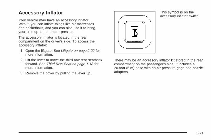
Accessory InflatorYour vehicle may have an accessory inflator.With it, you can inflate things like air mattressesand basketballs, and you can also use it to bringyour tires up to the proper pressure.
The accessory inflator is located in the rearcompartment on the driver’s side. To access theaccessory inflator:
1. Open the liftgate. See Liftgate on page 2-22 formore information.
2. Lift the lever to move the third row rear seatbackforward. See Third Row Seat on page 1-18 formore information.
3. Remove the cover by pulling the lever up.
This symbol is on theaccessory inflator switch.
There may be an accessory inflator kit stored in the rearcompartment on the passenger’s side. It includes a20-foot (6 m) hose with an air pressure gage and nozzleadapters.
5-71
{CAUTION:
Inflating something too much can make it explode,and you or others could be injured. Be sure toread the inflator instructions, and inflate any objectonly to its recommended pressure.
To use your accessory inflator system:
1. Turn the ignition to ACCESSORY or RUN.
2. Attach the appropriate nozzle adapter, if required,to the end of the hose that has the pressure gage.
3. Attach that end of the hose to the object you wishto inflate.
4. Remove the protective cap covering the outlet.
5. Attach the other end of the hose to the outlet.
6. Press the accessory inflator switch. The light in theswitch will come on to show the system is working.
If the accessory inflator system does not turn on orthe light does not come on, the fuse may be blown orinstalled incorrectly. See Fuses and Circuit Breakerson page 5-98 or see your dealer/retailer for service.
Your accessory inflator will automatically shut off afterabout 10 minutes. The light in the switch will blink.After about one minute you can use the system again.Press the switch and the indicator light will come on.
Notice: If you run the accessory inflator longerthan 30 minutes at a time, you could damagethe inflator. The repairs would not be covered byyour warranty. Run the inflator for short periods oftime only.
After running the accessory inflator for 30 minutes,wait at least 10 minutes before restarting the accessoryinflator.
To turn off the inflator:
1. Press the switch and detach the hose, first from theinflated object, then from the outlet.
2. Put the protective cap back on.
3. Place the inflator kit tools in the pouch, and store inthe rear compartment on the passenger’s side.
To put the cover back on, line up the tabs at the bottomof the cover and put it in place. Push down the tab tosecure the cover.
5-72
If a Tire Goes FlatIt is unusual for a tire to blowout while you are driving,especially if you maintain your vehicle’s tires properly.If air goes out of a tire, it is much more likely to leakout slowly. But if you should ever have a blowout, hereare a few tips about what to expect and what to do:
If a front tire fails, the flat tire creates a drag that pullsthe vehicle toward that side. Take your foot off theaccelerator pedal and grip the steering wheel firmly.Steer to maintain lane position, and then gently braketo a stop well out of the traffic lane.
A rear blowout, particularly on a curve, acts much like askid and may require the same correction you would usein a skid. In any rear blowout remove your foot from theaccelerator pedal. Get the vehicle under control bysteering the way you want the vehicle to go. It may bevery bumpy and noisy, but you can still steer. Gentlybrake to a stop, well off the road if possible.
{CAUTION:
Lifting a vehicle and getting under it to domaintenance or repairs is dangerous without theappropriate safety equipment and training. The jackprovided with your vehicle is designed only forchanging a flat tire. If it is used for anything else,you or others could be badly injured or killed if thevehicle slips off the jack. Use the jack provided withyour vehicle only for changing a flat tire.
If a tire goes flat, the next part shows how to use thejacking equipment to change a flat tire safely.
5-73
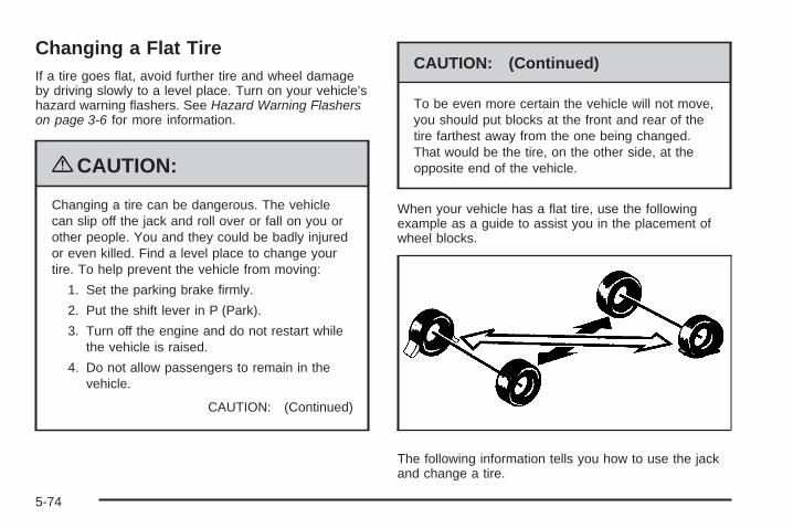
Changing a Flat TireIf a tire goes flat, avoid further tire and wheel damageby driving slowly to a level place. Turn on your vehicle’shazard warning flashers. See Hazard Warning Flasherson page 3-6 for more information.
{CAUTION:
Changing a tire can be dangerous. The vehiclecan slip off the jack and roll over or fall on you orother people. You and they could be badly injuredor even killed. Find a level place to change yourtire. To help prevent the vehicle from moving:
1. Set the parking brake firmly.
2. Put the shift lever in P (Park).
3. Turn off the engine and do not restart whilethe vehicle is raised.
4. Do not allow passengers to remain in thevehicle.
CAUTION: (Continued)
CAUTION: (Continued)
To be even more certain the vehicle will not move,you should put blocks at the front and rear of thetire farthest away from the one being changed.That would be the tire, on the other side, at theopposite end of the vehicle.
When your vehicle has a flat tire, use the followingexample as a guide to assist you in the placement ofwheel blocks.
The following information tells you how to use the jackand change a tire.
5-74
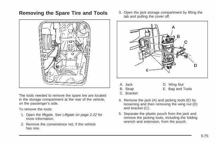
Removing the Spare Tire and Tools
The tools needed to remove the spare tire are locatedin the storage compartment at the rear of the vehicle,on the passenger’s side.
To remove the tools:
1. Open the liftgate. See Liftgate on page 2-22 formore information.
2. Remove the convenience net, if the vehiclehas one.
3. Open the jack storage compartment by lifting thetab and pulling the cover off.
A. JackB. StrapC. Bracket
D. Wing NutE. Bag and Tools
4. Remove the jack (A) and jacking tools (E) byloosening and then removing the wing nut (D)and bracket (C).
5. Separate the plastic pouch from the jack andremove the jacking tools, including the foldingwrench and extension, from the pouch.
5-75
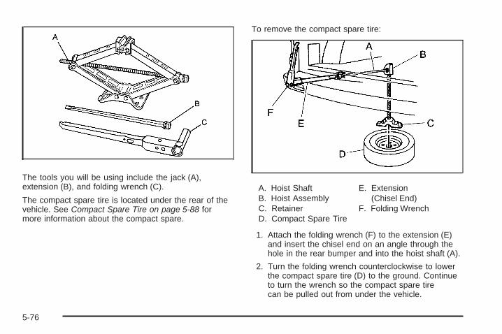
The tools you will be using include the jack (A),extension (B), and folding wrench (C).
The compact spare tire is located under the rear of thevehicle. See Compact Spare Tire on page 5-88 formore information about the compact spare.
To remove the compact spare tire:
A. Hoist ShaftB. Hoist AssemblyC. RetainerD. Compact Spare Tire
E. Extension(Chisel End)
F. Folding Wrench
1. Attach the folding wrench (F) to the extension (E)and insert the chisel end on an angle through thehole in the rear bumper and into the hoist shaft (A).
2. Turn the folding wrench counterclockwise to lowerthe compact spare tire (D) to the ground. Continueto turn the wrench so the compact spare tirecan be pulled out from under the vehicle.
5-76
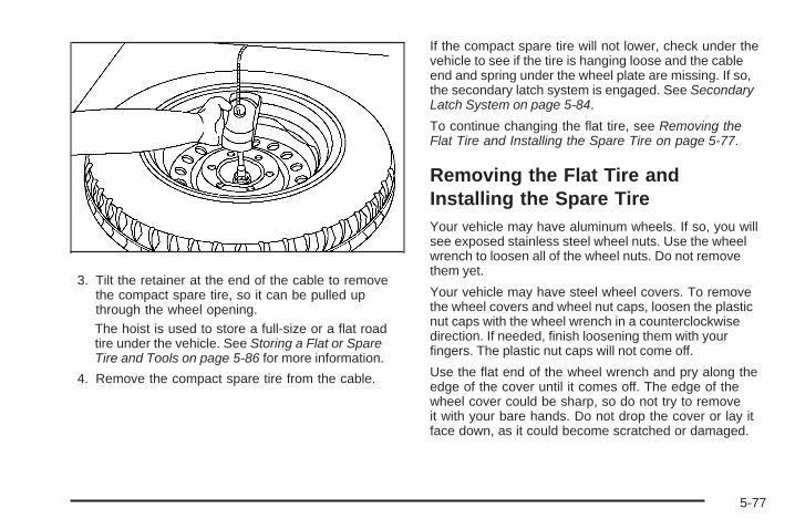
3. Tilt the retainer at the end of the cable to removethe compact spare tire, so it can be pulled upthrough the wheel opening.The hoist is used to store a full-size or a flat roadtire under the vehicle. See Storing a Flat or SpareTire and Tools on page 5-86 for more information.
4. Remove the compact spare tire from the cable.
If the compact spare tire will not lower, check under thevehicle to see if the tire is hanging loose and the cableend and spring under the wheel plate are missing. If so,the secondary latch system is engaged. See SecondaryLatch System on page 5-84.
To continue changing the flat tire, see Removing theFlat Tire and Installing the Spare Tire on page 5-77.
Removing the Flat Tire andInstalling the Spare TireYour vehicle may have aluminum wheels. If so, you willsee exposed stainless steel wheel nuts. Use the wheelwrench to loosen all of the wheel nuts. Do not removethem yet.
Your vehicle may have steel wheel covers. To removethe wheel covers and wheel nut caps, loosen the plasticnut caps with the wheel wrench in a counterclockwisedirection. If needed, finish loosening them with yourfingers. The plastic nut caps will not come off.
Use the flat end of the wheel wrench and pry along theedge of the cover until it comes off. The edge of thewheel cover could be sharp, so do not try to removeit with your bare hands. Do not drop the cover or lay itface down, as it could become scratched or damaged.
5-77
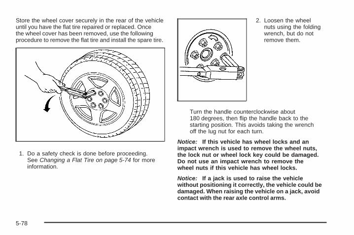
Store the wheel cover securely in the rear of the vehicleuntil you have the flat tire repaired or replaced. Oncethe wheel cover has been removed, use the followingprocedure to remove the flat tire and install the spare tire.
1. Do a safety check is done before proceeding.See Changing a Flat Tire on page 5-74 for moreinformation.
2. Loosen the wheelnuts using the foldingwrench, but do notremove them.
Turn the handle counterclockwise about180 degrees, then flip the handle back to thestarting position. This avoids taking the wrenchoff the lug nut for each turn.
Notice: If this vehicle has wheel locks and animpact wrench is used to remove the wheel nuts,the lock nut or wheel lock key could be damaged.Do not use an impact wrench to remove thewheel nuts if this vehicle has wheel locks.
Notice: If a jack is used to raise the vehiclewithout positioning it correctly, the vehicle could bedamaged. When raising the vehicle on a jack, avoidcontact with the rear axle control arms.
5-78
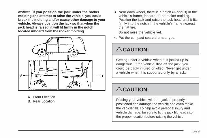
Notice: If you position the jack under the rockermolding and attempt to raise the vehicle, you couldbreak the molding and/or cause other damage to yourvehicle. Always position the jack so that when thejack head is raised, it will fit firmly in the notchlocated inboard from the rocker molding.
A. Front LocationB. Rear Location
3. Near each wheel, there is a notch (A and B) in thevehicle’s frame, inboard of the rocker molding.Position the jack and raise the jack head until it fitsfirmly into the notch in the vehicle’s frame nearestthe flat tire.Do not raise the vehicle yet.
4. Put the compact spare tire near you.
{CAUTION:
Getting under a vehicle when it is jacked up isdangerous. If the vehicle slips off the jack, youcould be badly injured or killed. Never get undera vehicle when it is supported only by a jack.
{CAUTION:
Raising your vehicle with the jack improperlypositioned can damage the vehicle and even makethe vehicle fall. To help avoid personal injury andvehicle damage, be sure to fit the jack lift head intothe proper location before raising the vehicle.
5-79
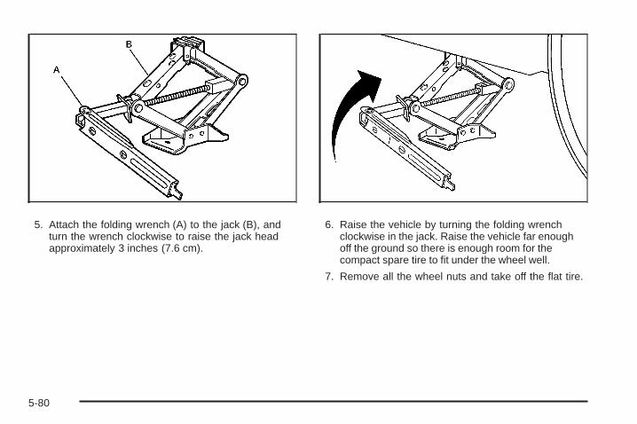
5. Attach the folding wrench (A) to the jack (B), andturn the wrench clockwise to raise the jack headapproximately 3 inches (7.6 cm).
6. Raise the vehicle by turning the folding wrenchclockwise in the jack. Raise the vehicle far enoughoff the ground so there is enough room for thecompact spare tire to fit under the wheel well.
7. Remove all the wheel nuts and take off the flat tire.
5-80
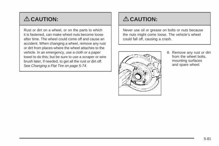
{CAUTION:
Rust or dirt on a wheel, or on the parts to whichit is fastened, can make wheel nuts become looseafter time. The wheel could come off and cause anaccident. When changing a wheel, remove any rustor dirt from places where the wheel attaches to thevehicle. In an emergency, use a cloth or a papertowel to do this; but be sure to use a scraper or wirebrush later, if needed, to get all the rust or dirt off.See Changing a Flat Tire on page 5-74.
{CAUTION:
Never use oil or grease on bolts or nuts becausethe nuts might come loose. The vehicle’s wheelcould fall off, causing a crash.
8. Remove any rust or dirtfrom the wheel bolts,mounting surfacesand spare wheel.
5-81
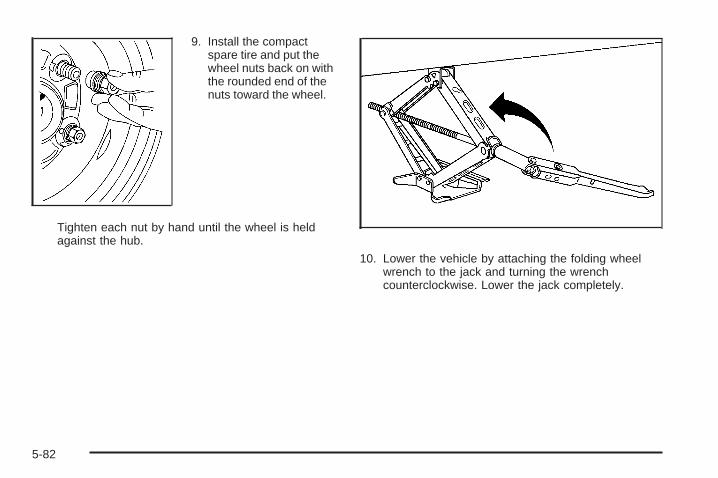
9. Install the compactspare tire and put thewheel nuts back on withthe rounded end of thenuts toward the wheel.
Tighten each nut by hand until the wheel is heldagainst the hub.
10. Lower the vehicle by attaching the folding wheelwrench to the jack and turning the wrenchcounterclockwise. Lower the jack completely.
5-82
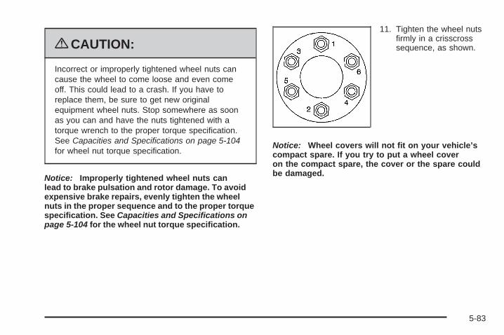
{CAUTION:
Incorrect or improperly tightened wheel nuts cancause the wheel to come loose and even comeoff. This could lead to a crash. If you have toreplace them, be sure to get new originalequipment wheel nuts. Stop somewhere as soonas you can and have the nuts tightened with atorque wrench to the proper torque specification.See Capacities and Specifications on page 5-104for wheel nut torque specification.
Notice: Improperly tightened wheel nuts canlead to brake pulsation and rotor damage. To avoidexpensive brake repairs, evenly tighten the wheelnuts in the proper sequence and to the proper torquespecification. See Capacities and Specifications onpage 5-104 for the wheel nut torque specification.
11. Tighten the wheel nutsfirmly in a crisscrosssequence, as shown.
Notice: Wheel covers will not fit on your vehicle’scompact spare. If you try to put a wheel coveron the compact spare, the cover or the spare couldbe damaged.
5-83
Secondary Latch SystemYour vehicle may have an underbody-mounted tirehoist assembly equipped with a secondary latch system.It is designed to stop a tire from suddenly falling off yourvehicle if the cable holding the spare tire is damaged.For the secondary latch to work, the tire must be stowedwith the valve stem pointing down.
Your vehicle uses the underbody tire hoist assemblyto store either the compact spare or a flat road tire. SeeStoring a Flat or Spare Tire and Tools on page 5-86for instructions on storing the spare or flat tire correctly.
{CAUTION:
Before beginning this procedure read all theinstructions. Failure to read and follow theinstructions could damage the hoist assemblyand you and others could get hurt. Read andfollow the instructions listed next.
{CAUTION:
Someone standing too close during the procedurecould be injured by the jack. If the spare tire doesnot slide off the jack completely, make sure noone is behind you or on either side of you as youpull the jack out from the under spare.
5-84
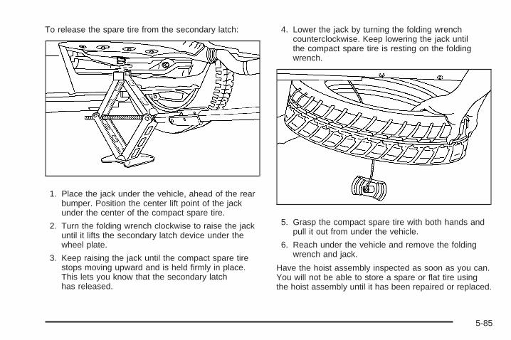
To release the spare tire from the secondary latch:
1. Place the jack under the vehicle, ahead of the rearbumper. Position the center lift point of the jackunder the center of the compact spare tire.
2. Turn the folding wrench clockwise to raise the jackuntil it lifts the secondary latch device under thewheel plate.
3. Keep raising the jack until the compact spare tirestops moving upward and is held firmly in place.This lets you know that the secondary latchhas released.
4. Lower the jack by turning the folding wrenchcounterclockwise. Keep lowering the jack untilthe compact spare tire is resting on the foldingwrench.
5. Grasp the compact spare tire with both hands andpull it out from under the vehicle.
6. Reach under the vehicle and remove the foldingwrench and jack.
Have the hoist assembly inspected as soon as you can.You will not be able to store a spare or flat tire usingthe hoist assembly until it has been repaired or replaced.
5-85
Storing a Flat or Spare Tire andTools
{CAUTION:
Storing a jack, a tire, or other equipment in thepassenger compartment of the vehicle couldcause injury. In a sudden stop or collision, looseequipment could strike someone. Store all these inthe proper place.
Storing the Flat or Spare Tire
{CAUTION:
The underbody-mounted spare tire needs to bestored with the valve stem pointing down. If thespare tire is stored with the valve stem pointingupwards, the secondary latch will not work properlyand the spare tire could loosen and suddenly fallfrom the vehicle. If this happened when the vehiclewas being driven, the tire might contact a person oranother vehicle, causing injury and damage to itself.Be sure the underbody-mounted spare tire is storedwith the valve stem pointing down.
5-86
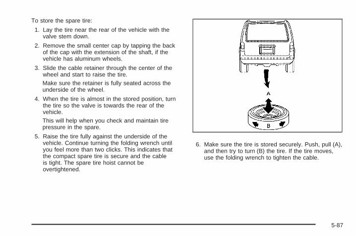
To store the spare tire:
1. Lay the tire near the rear of the vehicle with thevalve stem down.
2. Remove the small center cap by tapping the backof the cap with the extension of the shaft, if thevehicle has aluminum wheels.
3. Slide the cable retainer through the center of thewheel and start to raise the tire.Make sure the retainer is fully seated across theunderside of the wheel.
4. When the tire is almost in the stored position, turnthe tire so the valve is towards the rear of thevehicle.This will help when you check and maintain tirepressure in the spare.
5. Raise the tire fully against the underside of thevehicle. Continue turning the folding wrench untilyou feel more than two clicks. This indicates thatthe compact spare tire is secure and the cableis tight. The spare tire hoist cannot beovertightened.
6. Make sure the tire is stored securely. Push, pull (A),and then try to turn (B) the tire. If the tire moves,use the folding wrench to tighten the cable.
5-87
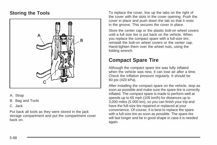
Storing the Tools
A. StrapB. Bag and ToolsC. Jack
Put back all tools as they were stored in the jackstorage compartment and put the compartment coverback on.
To replace the cover, line up the tabs on the right ofthe cover with the slots in the cover opening. Push thecover in place and push down the tab so that it restsin the groove. This secures the cover in place.
Store the center cap or the plastic bolt-on wheel coversuntil a full size tire is put back on the vehicle. Whenyou replace the compact spare with a full-size tire,reinstall the bolt-on wheel covers or the center cap.Hand-tighten them over the wheel nuts, using thefolding wrench.
Compact Spare TireAlthough the compact spare tire was fully inflatedwhen the vehicle was new, it can lose air after a time.Check the inflation pressure regularly. It should be60 psi (420 kPa).
After installing the compact spare on the vehicle, stop assoon as possible and make sure the spare tire is correctlyinflated. The compact spare is made to perform well atspeeds up to 65 mph (105 km/h) for distances up to3,000 miles (5 000 km), so you can finish your trip andhave the full-size tire repaired or replaced at yourconvenience. Of course, it is best to replace the sparewith a full-size tire as soon as possible. The spare tirewill last longer and be in good shape in case it is neededagain.
5-88
Notice: When the compact spare is installed,do not take the vehicle through an automatic carwash with guide rails. The compact spare canget caught on the rails which can damage thetire, wheel and other parts of the vehicle.
Do not use the compact spare on other vehicles.
And do not mix the compact spare tire or wheel withother wheels or tires. They will not fit. Keep thespare tire and its wheel together.
Notice: Tire chains will not fit the compact spare.Using them can damage the vehicle and can damagethe chains too. Do not use tire chains on thecompact spare.
Appearance Care
Interior CleaningYour vehicle’s interior will continue to look its best if it iscleaned often. Although not always visible, dust and dirtcan accumulate on your upholstery. Dirt can damagecarpet, fabric, leather, and plastic surfaces. Regularvacuuming is recommended to remove particles fromyour upholstery. It is important to keep your upholsteryfrom becoming and remaining heavily soiled. Soils shouldbe removed as quickly as possible. Your vehicle’s interiormay experience extremes of heat that could cause stainsto set rapidly.
Lighter colored interiors may require more frequentcleaning. Use care because newspapers and garmentsthat transfer color to your home furnishings may alsotransfer color to your vehicle’s interior.
5-89
When cleaning your vehicle’s interior, only use cleanersspecifically designed for the surfaces being cleaned.Permanent damage may result from using cleaners onsurfaces for which they were not intended. Use glasscleaner only on glass. Remove any accidental over-sprayfrom other surfaces immediately. To prevent over-spray,apply cleaner directly to the cleaning cloth.
Notice: If you use abrasive cleaners when cleaningglass surfaces on your vehicle, you could scratchthe glass and/or cause damage to the rear windowdefogger. When cleaning the glass on yourvehicle, use only a soft cloth and glass cleaner.
Many cleaners contain solvents that may becomeconcentrated in your vehicle’s breathing space.Before using cleaners, read and adhere to all safetyinstructions on the label. While cleaning your vehicle’sinterior, maintain adequate ventilation by openingyour vehicle’s doors and windows.
Dust may be removed from small buttons and knobsusing a small brush with soft bristles.
Your dealer/retailer has a product for cleaning yourvehicle’s glass. Should it become necessary, you canalso obtain a product from your dealer/retailer to removeodors from your vehicle’s upholstery.
Do not clean your vehicle using:
• A knife or any other sharp object to remove a soilfrom any interior surface.
• A stiff brush. It can cause damage to your vehicle’sinterior surfaces.
• Heavy pressure or aggressive rubbing with acleaning cloth. Use of heavy pressure can damageyour interior and does not improve the effectivenessof soil removal.
• Laundry detergents or dishwashing soaps withdegreasers can leave residue that streaks andattracts dirt. For liquid cleaners, about 20 dropsper gallon (3.78 L) of water is a good guide.Use only mild, neutral-pH soaps.
• Too much cleaner that saturates the upholstery.
• Organic solvents such as naptha, alcohol, etc. thatcan damage your vehicle’s interior.
5-90

Fabric/CarpetUse a vacuum cleaner with a soft brush attachmentfrequently to remove dust and loose dirt. A canistervacuum with a beater bar in the nozzle may onlybe used on floor carpet and carpeted floor mats.For any soil, always try to remove it first with plainwater or club soda. Before cleaning, gently removeas much of the soil as possible using one of thefollowing techniques:• For liquids: gently blot the remaining soil with a
paper towel. Allow the soil to absorb into thepaper towel until no more can be removed.
• For solid dry soils: remove as much as possibleand then vacuum.
To clean:1. Saturate a lint-free, clean white cloth with water or
club soda.2. Wring the cloth to remove excess moisture.3. Start on the outside edge of the soil and gently rub
toward the center. Continue cleaning, using a cleanarea of the cloth each time it becomes soiled.
4. Continue to gently rub the soiled area until thecleaning cloth remains clean.
5. If the soil is not completely removed, use a mildsoap solution and repeat the cleaning processthat was used with plain water.
If any of the soil remains, a commercial fabric cleaneror spot lifter may be necessary. When a commercialupholstery cleaner or spot lifter is to be used, testa small hidden area for colorfastness first. If the locallycleaned area gives any impression that a ringformation may result, clean the entire surface.
After the cleaning process has been completed, a papertowel can be used to blot excess moisture from thefabric or carpet.
LeatherA soft cloth dampened with water can be used toremove dust. If a more thorough cleaning is necessary,a soft cloth dampened with a mild soap solution can beused. Allow the leather to dry naturally. Do not use heatto dry. Never use steam to clean leather. Never use spotlifters or spot removers on leather. Many commercialleather cleaners and coatings that are sold to preserveand protect leather may permanently change theappearance and feel of your leather and are notrecommended. Do not use silicone or wax-basedproducts, or those containing organic solvents to cleanyour vehicle’s interior because they can alter theappearance by increasing the gloss in a non-uniformmanner. Never use shoe polish on leather.
5-91
Instrument Panel, Vinyl, and OtherPlastic SurfacesA soft cloth dampened with water may be used toremove dust. If a more thorough cleaning is necessary, aclean soft cloth dampened with a mild soap solution canbe used to gently remove dust and dirt. Never use spotlifters or removers on plastic surfaces. Many commercialcleaners and coatings that are sold to preserve andprotect soft plastic surfaces may permanently changethe appearance and feel of your interior and are notrecommended. Do not use silicone or wax-basedproducts, or those containing organic solvents to cleanyour vehicle’s interior because they can alter theappearance by increasing the gloss in a non-uniformmanner.
Some commercial products may increase gloss on yourinstrument panel. The increase in gloss may causeannoying reflections in the windshield and even makeit difficult to see through the windshield under certainconditions.
Child Restraint PadThe built-in child restraint pad is attached to the seatframe with fastener strips. You can remove the pad andhand wash it with mild soap and water.
Care of Safety Belts and Built-inChild Restraint HarnessKeep the safety belts and the built-in child restraintharness clean and dry.
{CAUTION:
Do not bleach or dye safety belts or the built-inchild restraint harness. If you do, they may beseverely weakened. In a crash, they might not beable to provide adequate protection. Clean thesafety belts and the child restraint harness onlywith mild soap and lukewarm water.
WeatherstripsSilicone grease on weatherstrips will make them lastlonger, seal better, and not stick or squeak. Applysilicone grease with a clean cloth. During very cold,damp weather frequent application may be required.See Recommended Fluids and Lubricants on page 6-11.
5-92
Washing Your VehicleThe best way to preserve your vehicle’s finish is to keepit clean by washing it often.
Notice: Certain cleaners contain chemicals thatcan damage the emblems or nameplates on yourvehicle. Check the cleaning product label. If it statesthat it should not be used on plastic parts, do not useit on your vehicle or damage may occur and it wouldnot be covered by the warranty.
Do not wash the vehicle in direct sunlight. Use a carwashing soap. Do not use cleaning agents that arepetroleum based or that contain acid or abrasives, asthey can damage the paint, metal or plastic on yourvehicle. Approved cleaning products can be obtainedfrom your dealer/retailer. Follow all manufacturers’directions regarding correct product usage, necessarysafety precautions and appropriate disposal of anyvehicle care product.
Rinse the vehicle well, before washing and after toremove all cleaning agents completely. If they areallowed to dry on the surface, they could stain.
Dry the finish with a soft, clean chamois or an all-cottontowel to avoid surface scratches and water spotting.
High pressure car washes may cause water to enterthe vehicle. Avoid using high pressure washes closerthan 12 inches (30 cm) to the surface of the vehicle.Use of power washers exceeding 1,200 psi (8 274 kPa)can result in damage or removal of paint and decals.
Cleaning Exterior Lamps/LensesUse only lukewarm or cold water, a soft cloth and acar washing soap to clean exterior lamps and lenses.Follow instructions under Washing Your Vehicle onpage 5-93.
5-93
Finish CareOccasional waxing or mild polishing of your vehicle byhand may be necessary to remove residue from thepaint finish. You can get approved cleaning productsfrom your dealer/retailer.
If your vehicle has a basecoat/clearcoat paint finish, theclearcoat gives more depth and gloss to the coloredbasecoat. Always use waxes and polishes that arenon-abrasive and made for a basecoat/clearcoatpaint finish.
Notice: Machine compounding or aggressivepolishing on a basecoat/clearcoat paint finishmay damage it. Use only non-abrasive waxes andpolishes that are made for a basecoat/clearcoatpaint finish on your vehicle.
Foreign materials such as calcium chloride and othersalts, ice melting agents, road oil and tar, tree sap, birddroppings, chemicals from industrial chimneys, etc., candamage your vehicle’s finish if they remain on paintedsurfaces. Wash the vehicle as soon as possible. Ifnecessary, use non-abrasive cleaners that are markedsafe for painted surfaces to remove foreign matter.
Exterior painted surfaces are subject to aging, weatherand chemical fallout that can take their toll over aperiod of years. You can help to keep the paint finishlooking new by keeping your vehicle garaged or coveredwhenever possible.
Protecting Exterior Bright Metal PartsBright metal parts should be cleaned regularly to keeptheir luster. Washing with water is all that is usuallyneeded. However, you may use chrome polish onchrome or stainless steel trim, if necessary.
Use special care with aluminum trim. To avoiddamaging protective trim, never use auto or chromepolish, steam or caustic soap to clean aluminum.A coating of wax, rubbed to high polish, is recommendedfor all bright metal parts.
Windshield, Backglass, and WiperBladesClean the outside of the windshield and backglass withglass cleaner.
Clean the rubber blades using a lint free cloth or papertowel soaked with windshield washer fluid or a milddetergent. Wash the windshield thoroughly when youclean the blades. Bugs, road grime, sap and a buildupof vehicle wash/wax treatments may cause wiperstreaking. Replace the wiper blades if they are wornor damaged.
5-94
Wipers can be damaged by:
• Extreme dusty conditions
• Sand and salt
• Heat and sun
• Snow and ice, without proper removal
Aluminum WheelsNotice: If you use strong soaps, chemicals,abrasive polishes, cleaners, brushes, or cleanersthat contain acid on aluminum or chrome-platedwheels, you could damage the surface of thewheel(s). The repairs would not be covered by yourwarranty. Use only approved cleaners on aluminumor chrome-plated wheels.
Keep the wheels clean using a soft clean cloth with mildsoap and water. Rinse with clean water. After rinsingthoroughly, dry with a soft clean towel. A wax may thenbe applied.
Notice: Using chrome polish on aluminum wheelscould damage the wheels. The repairs would notbe covered by your warranty. Use chrome polishon chrome wheels only.
The surface of these wheels is similar to the paintedsurface of the vehicle. Do not use strong soaps,chemicals, abrasive polishes, abrasive cleaners,cleaners with acid, or abrasive cleaning brusheson them because the surface could be damaged.Do not use chrome polish on aluminum wheels.
Notice: If you drive your vehicle through anautomatic car wash that has silicone carbide tirecleaning brushes, you could damage the aluminumor chrome-plated wheels. The repairs would notbe covered by your warranty. Never drive a vehicleequipped with aluminum or chrome-plated wheelsthrough an automatic car wash that uses siliconecarbide tire cleaning brushes.
TiresTo clean the tires, use a stiff brush with tire cleaner.
Notice: Using petroleum-based tire dressingproducts on your vehicle may damage the paintfinish and/or tires. When applying a tire dressing,always wipe off any overspray from all paintedsurfaces on your vehicle.
5-95
Sheet Metal DamageIf the vehicle is damaged and requires sheet metalrepair or replacement, make sure the body repair shopapplies anti-corrosion material to parts repaired orreplaced to restore corrosion protection.
Original manufacturer replacement parts will providethe corrosion protection while maintaining the vehiclewarranty.
Finish DamageAny stone chips, fractures or deep scratches in thefinish should be repaired right away. Bare metalwill corrode quickly and may develop into majorrepair expense.
Minor chips and scratches can be repaired with touch-upmaterials available from your dealer/retailer. Largerareas of finish damage can be corrected in yourdealer’s/retailer’s body and paint shop.
Underbody MaintenanceChemicals used for ice and snow removal and dustcontrol can collect on the underbody. If these arenot removed, corrosion and rust can develop on theunderbody parts such as fuel lines, frame, floor pan,and exhaust system even though they have corrosionprotection.
At least every spring, flush these materials from theunderbody with plain water. Clean any areas where mudand debris can collect. Dirt packed in close areas ofthe frame should be loosened before being flushed.Your dealer/retailer or an underbody car washing systemcan do this for you.
Chemical Paint SpottingSome weather and atmospheric conditions can create achemical fallout. Airborne pollutants can fall upon andattack painted surfaces on the vehicle. This damage cantake two forms: blotchy, ring-shaped discolorations,and small, irregular dark spots etched into thepaint surface.
Although no defect in the paint job causes this, we willrepair, at no charge to the owner, the surfaces ofnew vehicles damaged by this fallout condition within12 months or 12,000 miles (20 000 km) of purchase,whichever occurs first.
5-96
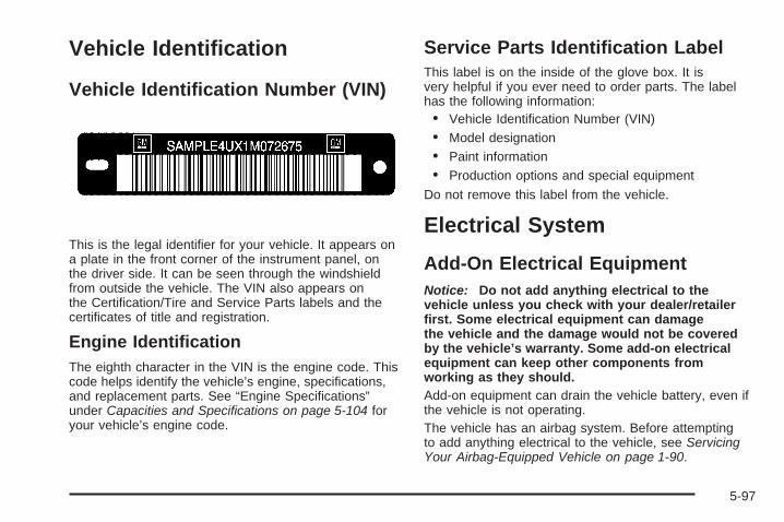
Vehicle Identification
Vehicle Identification Number (VIN)
This is the legal identifier for your vehicle. It appears ona plate in the front corner of the instrument panel, onthe driver side. It can be seen through the windshieldfrom outside the vehicle. The VIN also appears onthe Certification/Tire and Service Parts labels and thecertificates of title and registration.
Engine IdentificationThe eighth character in the VIN is the engine code. Thiscode helps identify the vehicle’s engine, specifications,and replacement parts. See “Engine Specifications”under Capacities and Specifications on page 5-104 foryour vehicle’s engine code.
Service Parts Identification LabelThis label is on the inside of the glove box. It isvery helpful if you ever need to order parts. The labelhas the following information:• Vehicle Identification Number (VIN)• Model designation• Paint information• Production options and special equipment
Do not remove this label from the vehicle.
Electrical System
Add-On Electrical EquipmentNotice: Do not add anything electrical to thevehicle unless you check with your dealer/retailerfirst. Some electrical equipment can damagethe vehicle and the damage would not be coveredby the vehicle’s warranty. Some add-on electricalequipment can keep other components fromworking as they should.Add-on equipment can drain the vehicle battery, even ifthe vehicle is not operating.The vehicle has an airbag system. Before attemptingto add anything electrical to the vehicle, see ServicingYour Airbag-Equipped Vehicle on page 1-90.
5-97
Headlamp WiringThe headlamp wiring is protected by four internal fusesin the underhood fuse block. An electrical overloadwill cause the lamps to go on and off, or in some casesto remain off. If this happens, have your headlampwiring checked right away.
Windshield Wiper FusesThe windshield wiper motor is protected by an internalfuse in the underhood fuse block. If the motor overheatsdue to heavy snow, etc., the wiper will stop until themotor cools. If the overload is caused by some electricalproblem, be sure to get it fixed.
The rear washer pump is controlled by a relay locatedin the engine compartment, behind the windshieldwasher fluid reservoir. The rear wiper motor is protectedby a fuse located in the instrument panel fuse block.
Power Windows and OtherPower OptionsCircuit breakers in the instrument panel fuse panelprotect the power windows and other power accessories.When the current load is too heavy, the circuit breakeropens and closes, protecting the circuit until theproblem is fixed.
Fuses and Circuit BreakersThe wiring circuits in the vehicle are protected fromshort circuits by a combination of fuses, circuit breakersand fusible thermal links. This greatly reduces thechance of fires caused by electrical problems.
Look at the silver-colored band inside the fuse. If theband is broken or melted, replace the fuse. Be sure youreplace a bad fuse with a new one of the identicalsize and rating.
Fuses of the same amperage can be temporarilyborrowed from another fuse location, if a fuse goes out.Replace the fuse as soon as you can.
Instrument Panel Fuse BlockThe instrument panel fuse block is located at the rightend of the instrument panel, on the passenger sideof the vehicle. Open the front passenger door,and remove the cover, to access the fuse block.
Your vehicle may not have all of the fuses listed.
5-98
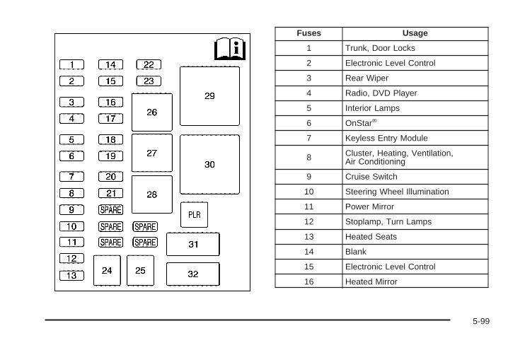
Fuses Usage
1 Trunk, Door Locks
2 Electronic Level Control
3 Rear Wiper
4 Radio, DVD Player
5 Interior Lamps
6 OnStar®
7 Keyless Entry Module
8 Cluster, Heating, Ventilation,Air Conditioning
9 Cruise Switch
10 Steering Wheel Illumination
11 Power Mirror
12 Stoplamp, Turn Lamps
13 Heated Seats
14 Blank
15 Electronic Level Control
16 Heated Mirror
5-99
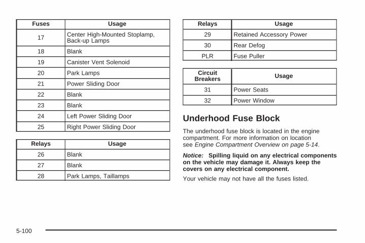
Fuses Usage
17 Center High-Mounted Stoplamp,Back-up Lamps
18 Blank
19 Canister Vent Solenoid
20 Park Lamps
21 Power Sliding Door
22 Blank
23 Blank
24 Left Power Sliding Door
25 Right Power Sliding Door
Relays Usage
26 Blank
27 Blank
28 Park Lamps, Taillamps
Relays Usage
29 Retained Accessory Power
30 Rear Defog
PLR Fuse Puller
CircuitBreakers Usage
31 Power Seats
32 Power Window
Underhood Fuse BlockThe underhood fuse block is located in the enginecompartment. For more information on locationsee Engine Compartment Overview on page 5-14.
Notice: Spilling liquid on any electrical componentson the vehicle may damage it. Always keep thecovers on any electrical component.
Your vehicle may not have all the fuses listed.
5-100
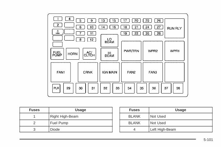
Fuses Usage
1 Right High-Beam
2 Fuel Pump
3 Diode
Fuses Usage
BLANK Not Used
BLANK Not Used
4 Left High-Beam
5-101

Fuses Usage
BLANK Not Used
BLANK Not Used
BLANK Not Used
5 Not Used
6 Air Conditioning Clutch
7 Horn
8 Left Low-Beam
9 Powertrain Control Module,Electronic Throttle Control
10 Not Used
11 Transmission Solenoid
12 Right Low-Beam
13 Antilock Brake System
14 Powertrain Control Module Ignition
15 Electronic Ignition
Fuses Usage
16 Fuel Injector
17 Climate Control, RPA, CruiseControl
18 Electronic Throttle Control
19 Engine Sensor, Evaporator
20 Airbag
21 Not Used
22 Not Used
23 Auxiliary Power
24 Front Windshield Washer
25 AC/DC Inverter
26 Rear Blower
27 Front Blower
28 Front Windshield Wiper
5-102
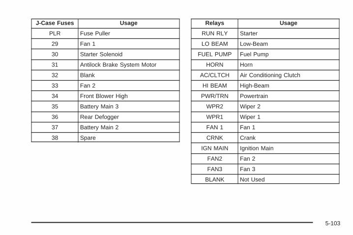
J-Case Fuses Usage
PLR Fuse Puller
29 Fan 1
30 Starter Solenoid
31 Antilock Brake System Motor
32 Blank
33 Fan 2
34 Front Blower High
35 Battery Main 3
36 Rear Defogger
37 Battery Main 2
38 Spare
Relays Usage
RUN RLY Starter
LO BEAM Low-Beam
FUEL PUMP Fuel Pump
HORN Horn
AC/CLTCH Air Conditioning Clutch
HI BEAM High-Beam
PWR/TRN Powertrain
WPR2 Wiper 2
WPR1 Wiper 1
FAN 1 Fan 1
CRNK Crank
IGN MAIN Ignition Main
FAN2 Fan 2
FAN3 Fan 3
BLANK Not Used
5-103
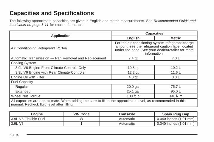
Capacities and SpecificationsThe following approximate capacities are given in English and metric measurements. See Recommended Fluids andLubricants on page 6-11 for more information.
ApplicationCapacities
English Metric
Air Conditioning Refrigerant R134a
For the air conditioning system refrigerant chargeamount, see the refrigerant caution label locatedunder the hood. See your dealer/retailer for more
information.Automatic Transmission — Pan Removal and Replacement 7.4 qt 7.0 LCooling System
3.9L V6 Engine Front Climate Controls Only 10.8 qt 10.2 L3.9L V6 Engine with Rear Climate Controls 12.2 qt 11.6 L
Engine Oil with Filter 4.0 qt 3.8 LFuel Capacity
Regular 20.0 gal 75.7 LExtended 25.1 gal 95.0 L
Wheel Nut Torque 100 ft lb 140 Y
All capacities are approximate. When adding, be sure to fill to the approximate level, as recommended in thismanual. Recheck fluid level after filling.
Engine VIN Code Transaxle Spark Plug Gap3.9L V6 Flexible Fuel W Automatic 0.040 inches (1.01 mm)3.9L V6 1 Automatic 0.040 inches (1.01 mm)
5-104
Maintenance Schedule ......................................6-2Introduction ...................................................6-2Maintenance Requirements ..............................6-2Your Vehicle and the Environment ....................6-2Using the Maintenance Schedule ......................6-3Scheduled Maintenance ...................................6-4Additional Required Services ............................6-6Maintenance Footnotes ...................................6-7
Owner Checks and Services ............................6-8At Each Fuel Fill ............................................6-8At Least Once a Month ...................................6-9At Least Once a Year .....................................6-9Recommended Fluids and Lubricants ...............6-11Maintenance Replacement Parts .....................6-13Engine Drive Belt Routing ..............................6-14Maintenance Record .....................................6-15
Section 6 Maintenance Schedule
6-1
Maintenance Schedule
IntroductionImportant: Keep engine oil at the proper level andchange as recommended.
Have you purchased the GM Protection Plan? The Plansupplements the vehicle warranties. See the Warrantyand Owner Assistance booklet or your dealer/retailer fordetails.
Maintenance RequirementsNotice: Maintenance intervals, checks, inspections,replacement parts, and recommended fluids andlubricants as prescribed in this manual are necessaryto keep this vehicle in good working condition. Anydamage caused by failure to follow scheduledmaintenance might not be covered by the vehiclewarranty.
Your Vehicle and the EnvironmentProper vehicle maintenance not only helps to keepthe vehicle in good working condition, but also helpsthe environment. All recommended maintenance isimportant. Improper vehicle maintenance can even affectthe quality of the air we breathe. Improper fluid levels orthe wrong tire inflation can increase the level of emissionsfrom the vehicle. To help protect the environment, and tokeep the vehicle in good condition, be sure to maintainthe vehicle properly.
6-2
Using the Maintenance ScheduleWe want to help keep this vehicle in good workingcondition. But we do not know exactly how you willdrive it. You might drive very short distances onlya few times a week. Or you might drive long distancesall the time in very hot, dusty weather. You mightuse the vehicle in making deliveries. Or you might driveit to work, to do errands, or in many other ways.
Because of all the different ways people use theirvehicles, maintenance needs vary. You might need morefrequent checks and replacements. So please readthe following and note how you drive. If you have anyquestions on how to keep the vehicle in good condition,see your dealer/retailer.
This schedule is for vehicles that:
• carry passengers and cargo within recommendedlimits on the Tire and Loading Information label.See Loading the Vehicle on page 4-19.
• are driven on reasonable road surfaces within legaldriving limits.
• use the recommended fuel. See Gasoline Octaneon page 5-6.
The services in Scheduled Maintenance on page 6-4should be performed when indicated. See AdditionalRequired Services on page 6-6 and MaintenanceFootnotes on page 6-7 for further information.
{CAUTION:
Performing maintenance work on a vehicle can bedangerous. In trying to do some jobs, you can beseriously injured. Do your own maintenance workonly if you have the required know-how and theproper tools and equipment for the job. If you haveany doubt, see your dealer/retailer to have aqualified technician do the work. See Doing YourOwn Service Work on page 5-4.
Some maintenance services can be complex. So, unlessyou are technically qualified and have the necessaryequipment, have your dealer/retailer do these jobs.
When you go to your dealer/retailer for service, trainedand supported service technicians will perform thework using genuine parts.
To purchase service information, see ServicePublications Ordering Information on page 7-15.
Owner Checks and Services on page 6-8 tells whatshould be checked, when to check it, and whatcan easily be done to help keep the vehicle in goodcondition.
6-3
The proper replacement parts, fluids, and lubricants touse are listed in Recommended Fluids and Lubricantson page 6-11 and Maintenance Replacement Partson page 6-13. When the vehicle is serviced, make surethese are used. All parts should be replaced and allnecessary repairs done before you or anyone elsedrives the vehicle. We recommend the use of genuineparts from your dealer/retailer.
Scheduled MaintenanceWhen the CHANGE OIL SOON message comes on,it means that service is required for your vehicle. Haveyour vehicle serviced as soon as possible within the next600 miles (1 000 km). It is possible that, if you are drivingunder the best conditions, the engine oil life system maynot indicate that vehicle service is necessary for over ayear. However, your engine oil and filter must be changedat least once a year and at this time the system must bereset. Your dealer/retailer has trained service technicianswho will perform this work using genuine parts and resetthe system.
If the engine oil life system is ever reset accidentally,you must service your vehicle within 3,000 miles(5 000 km) since your last service. Remember to resetthe oil life system whenever the oil is changed. SeeEngine Oil Life System on page 5-18 for information onthe Engine Oil Life System and resetting the system.
When the CHANGE OIL SOON message appears,certain services, checks, and inspections are required.Required services are described in the following for“Maintenance I” and “Maintenance II.” Generally, it isrecommended that your first service be Maintenance I,your second service be Maintenance II, and that youalternate Maintenance I and Maintenance II thereafter.However, in some cases, Maintenance II may berequired more often.
Maintenance I — Use Maintenance I if the CHANGEOIL SOON message comes on within 10 months sincethe vehicle was purchased or Maintenance II wasperformed.
Maintenance II — Use Maintenance II if the previousservice performed was Maintenance I. Always useMaintenance II whenever the message comes on10 months or more since the last service or if themessage has not come on at all for one year.
6-4
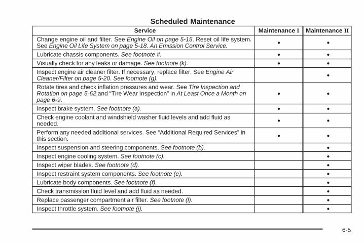
Scheduled MaintenanceService Maintenance I Maintenance II
Change engine oil and filter. See Engine Oil on page 5-15. Reset oil life system.See Engine Oil Life System on page 5-18. An Emission Control Service. • •
Lubricate chassis components. See footnote #. • •Visually check for any leaks or damage. See footnote (k). • •Inspect engine air cleaner filter. If necessary, replace filter. See Engine AirCleaner/Filter on page 5-20. See footnote (g). •
Rotate tires and check inflation pressures and wear. See Tire Inspection andRotation on page 5-62 and “Tire Wear Inspection” in At Least Once a Month onpage 6-9.
• •
Inspect brake system. See footnote (a). • •Check engine coolant and windshield washer fluid levels and add fluid asneeded. • •
Perform any needed additional services. See “Additional Required Services” inthis section. • •
Inspect suspension and steering components. See footnote (b). •Inspect engine cooling system. See footnote (c). •Inspect wiper blades. See footnote (d). •Inspect restraint system components. See footnote (e). •Lubricate body components. See footnote (f). •Check transmission fluid level and add fluid as needed. •Replace passenger compartment air filter. See footnote (l). •Inspect throttle system. See footnote (j). •
6-5
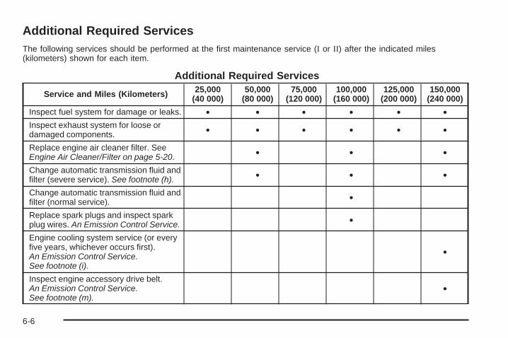
Additional Required ServicesThe following services should be performed at the first maintenance service (I or II) after the indicated miles(kilometers) shown for each item.
Additional Required Services
Service and Miles (Kilometers) 25,000(40 000)
50,000(80 000)
75,000(120 000)
100,000(160 000)
125,000(200 000)
150,000(240 000)
Inspect fuel system for damage or leaks. • • • • • •Inspect exhaust system for loose ordamaged components. • • • • • •
Replace engine air cleaner filter. SeeEngine Air Cleaner/Filter on page 5-20. • • •
Change automatic transmission fluid andfilter (severe service). See footnote (h). • • •
Change automatic transmission fluid andfilter (normal service). •
Replace spark plugs and inspect sparkplug wires. An Emission Control Service. •
Engine cooling system service (or everyfive years, whichever occurs first).An Emission Control Service.See footnote (i).
•
Inspect engine accessory drive belt.An Emission Control Service.See footnote (m).
•
6-6
Maintenance Footnotes# Lubricate the suspension, steering linkage, and theunderbody contact points and linkage.
(a) Visually inspect brake lines and hoses for properhook-up, binding, leaks, cracks, chafing, etc. Inspectdisc brake pads for wear and rotors for surfacecondition. Inspect other brake parts, including calipers,parking brake, etc. Check parking brake adjustment.
(b) Visually inspect front and rear suspension andsteering system for damaged, loose, or missing parts,signs of wear, or lack of lubrication. Inspect powersteering lines and hoses for proper hook-up, binding,leaks, cracks, chafing, etc.
(c) Visually inspect hoses and have them replaced ifthey are cracked, swollen, or deteriorated. Inspect allpipes, fittings and clamps; replace with genuine parts asneeded. To help ensure proper operation, a pressure testof the cooling system and pressure cap and cleaning theoutside of the radiator and air conditioning condenser isrecommended at least once a year.
(d) Inspect wiper blades for wear, cracking, orcontamination. Clean the windshield and wiper blades,if contaminated. Replace wiper blades that are wornor damaged. See Windshield Wiper Blade Replacementon page 5-46 and Windshield, Backglass, and WiperBlades on page 5-94 for more information.
(e) Make sure the safety belt reminder light and safetybelt assemblies are working properly. If your vehicle hasa built-in child restraint, make sure the harness straps,latch plates, buckle, clip, child head restraint, andanchorages are working properly. Look for any otherloose or damaged safety belt system parts. If you seeanything that might keep a safety belt system from doingits job, have it repaired. Have any torn or frayed safetybelts replaced. Also see Checking the Restraint Systemson page 1-92.
(f) Lubricate all key lock cylinders, hood latchassemblies, secondary latches, pivots, spring anchorand release pawl, hood and door hinges, rear foldingseats, liftgate hinges, fuel door hinge, power slidingdoor cable, and sliding door track(s). More frequentlubrication may be required when exposed to a corrosiveenvironment. Applying silicone grease on weatherstripswith a clean cloth will make them last longer, sealbetter, and not stick or squeak.
(g) If you drive regularly under dusty conditions, inspectthe filter at each engine oil change.
6-7
(h) Change automatic transmission fluid and filter if thevehicle is mainly driven under one or more of theseconditions:
− In heavy city traffic where the outside temperatureregularly reaches 90°F (32°C) or higher.
− In hilly or mountainous terrain.− When doing frequent trailer towing.− Uses such as found in taxi, police, or delivery
service.
(i) Drain, flush, and refill cooling system. See EngineCoolant on page 5-24 for what to use. Inspect hoses.Clean radiator, condenser, pressure cap, and filler neck.Pressure test the cooling system and pressure cap.
(j) Check system for interference or binding andfor damaged or missing parts. Replace parts as needed.Replace any components that have high effort orexcessive wear. Do not lubricate accelerator or cruisecontrol cables.
(k) A fluid loss in any vehicle system could indicate aproblem. Have the system inspected and repairedand the fluid level checked. Add fluid if needed.
(l) If you drive regularly under dusty conditions, the filtermay require replacement more often.
(m) Visually inspect belt for fraying, excessive cracks, orobvious damage. Replace belt if necessary.
Owner Checks and ServicesThese owner checks and services should be performedat the intervals specified to help ensure vehicle safety,dependability, and emission control performance. Yourdealer/retailer can assist with these checks and services.
Be sure any necessary repairs are completed at once.Whenever any fluids or lubricants are added to thevehicle, make sure they are the proper ones, as shownin Recommended Fluids and Lubricants on page 6-11.
At Each Fuel FillIt is important to perform these underhood checks ateach fuel fill.
Engine Oil Level Check
Notice: It is important to check the engine oilregularly and keep it at the proper level. Failure tokeep the engine oil at the proper level can causedamage to the engine not covered by the vehiclewarranty.
Check the engine oil level and add the proper oil ifnecessary. See Engine Oil on page 5-15.
6-8
Engine Coolant Level CheckCheck the engine coolant level and add DEX-COOL®
coolant mixture if necessary. See Engine Coolanton page 5-24.
Windshield Washer Fluid Level CheckCheck the windshield washer fluid level in the windshieldwasher fluid reservoir and add the proper fluid ifnecessary.
At Least Once a Month
Tire Inflation CheckInspect the vehicle’s tires and make sure they areinflated to the correct pressures. Do not forget tocheck the spare tire. See Inflation - Tire Pressure onpage 5-54. Check to make sure the spare tire is storedsecurely. See Changing a Flat Tire on page 5-74.
Tire Wear InspectionTire rotation may be required for high mileage highwaydrivers prior to the Engine Oil Life System servicenotification. Check the tires for wear and, if necessary,rotate the tires. See Tire Inspection and Rotation onpage 5-62.
At Least Once a Year
Starter Switch Check
{CAUTION:
When you are doing this inspection, the vehiclecould move suddenly. If the vehicle moves, you orothers could be injured.
1. Before starting this check, be sure there is enoughroom around the vehicle.
2. Firmly apply both the parking brake and the regularbrake. See Parking Brake on page 2-38.Do not use the accelerator pedal, and be ready toturn off the engine immediately if it starts.
3. Try to start the engine in each gear. The vehicleshould start only in P (Park) or N (Neutral). If thevehicle starts in any other position, contactyour dealer/retailer for service.
6-9
Automatic Transmission Shift LockControl System Check
{CAUTION:
When you are doing this inspection, the vehiclecould move suddenly. If the vehicle moves, you orothers could be injured.
1. Before starting this check, be sure there is enoughroom around the vehicle. It should be parked on alevel surface.
2. Firmly apply the parking brake. See Parking Brakeon page 2-38.Be ready to apply the regular brake immediately ifthe vehicle begins to move.
3. With the engine off, turn the ignition to ON/RUN,but do not start the engine. Without applying theregular brake, try to move the shift lever outof P (Park) with normal effort. If the shift levermoves out of P (Park), contact your dealer/retailerfor service.
Ignition Transmission Lock CheckWhile parked, and with the parking brake set, try to turnthe ignition to LOCK/OFF in each shift lever position.
• The ignition should turn to LOCK/OFF onlywhen the shift lever is in P (Park).
• The ignition key should come out only inLOCK/OFF.
Contact your dealer/retailer if service is required.
Parking Brake and AutomaticTransmission P (Park) MechanismCheck
{CAUTION:
When you are doing this check, the vehicle couldbegin to move. You or others could be injured andproperty could be damaged. Make sure there isroom in front of the vehicle in case it begins to roll.Be ready to apply the regular brake at onceshould the vehicle begin to move.
6-10
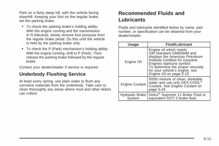
Park on a fairly steep hill, with the vehicle facingdownhill. Keeping your foot on the regular brake,set the parking brake.
• To check the parking brake’s holding ability:With the engine running and the transmissionin N (Neutral), slowly remove foot pressure fromthe regular brake pedal. Do this until the vehicleis held by the parking brake only.
• To check the P (Park) mechanism’s holding ability:With the engine running, shift to P (Park). Thenrelease the parking brake followed by the regularbrake.
Contact your dealer/retailer if service is required.
Underbody Flushing ServiceAt least every spring, use plain water to flush anycorrosive materials from the underbody. Take care toclean thoroughly any areas where mud and other debriscan collect.
Recommended Fluids andLubricantsFluids and lubricants identified below by name, partnumber, or specification can be obtained from yourdealer/retailer.
Usage Fluid/Lubricant
Engine Oil
Engine oil which meetsGM Standard GM6094M anddisplays the American PetroleumInstitute Certified for GasolineEngines starburst symbol.To determine the proper viscosityfor your vehicle’s engine, seeEngine Oil on page 5-15.
Engine Coolant50/50 mixture of clean, drinkablewater and use only DEX-COOL®
Coolant. See Engine Coolant onpage 5-24.
Hydraulic BrakeSystem
Delco® Supreme 11 Brake Fluid orequivalent DOT-3 brake fluid.
6-11
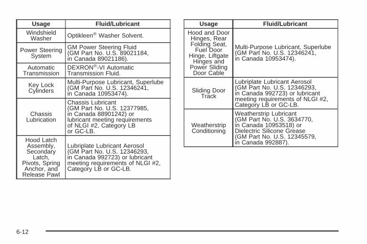
Usage Fluid/LubricantWindshield
Washer Optikleen® Washer Solvent.
Power SteeringSystem
GM Power Steering Fluid(GM Part No. U.S. 89021184,in Canada 89021186).
AutomaticTransmission
DEXRON®-VI AutomaticTransmission Fluid.
Key LockCylinders
Multi-Purpose Lubricant, Superlube(GM Part No. U.S. 12346241,in Canada 10953474).
ChassisLubrication
Chassis Lubricant(GM Part No. U.S. 12377985,in Canada 88901242) orlubricant meeting requirementsof NLGI #2, Category LBor GC-LB.
Hood LatchAssembly,Secondary
Latch,Pivots, SpringAnchor, and
Release Pawl
Lubriplate Lubricant Aerosol(GM Part No. U.S. 12346293,in Canada 992723) or lubricantmeeting requirements of NLGI #2,Category LB or GC-LB.
Usage Fluid/LubricantHood and DoorHinges, RearFolding Seat,
Fuel DoorHinge, Liftgate
Hinges andPower SlidingDoor Cable
Multi-Purpose Lubricant, Superlube(GM Part No. U.S. 12346241,in Canada 10953474).
Sliding DoorTrack
Lubriplate Lubricant Aerosol(GM Part No. U.S. 12346293,in Canada 992723) or lubricantmeeting requirements of NLGI #2,Category LB or GC-LB.
WeatherstripConditioning
Weatherstrip Lubricant(GM Part No. U.S. 3634770,in Canada 10953518) orDielectric Silicone Grease(GM Part No. U.S. 12345579,in Canada 992887).
6-12
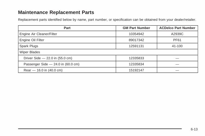
Maintenance Replacement PartsReplacement parts identified below by name, part number, or specification can be obtained from your dealer/retailer.
Part GM Part Number ACDelco Part Number
Engine Air Cleaner/Filter 10354942 A2939C
Engine Oil Filter 89017342 PF61
Spark Plugs 12591131 41-100
Wiper Blades
Driver Side — 22.0 in (55.0 cm) 12335833 —
Passenger Side — 24.0 in (60.0 cm) 12335834 —
Rear — 16.0 in (40.0 cm) 15192147 —
6-13
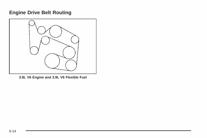
Engine Drive Belt Routing
3.9L V6 Engine and 3.9L V6 Flexible Fuel
6-14
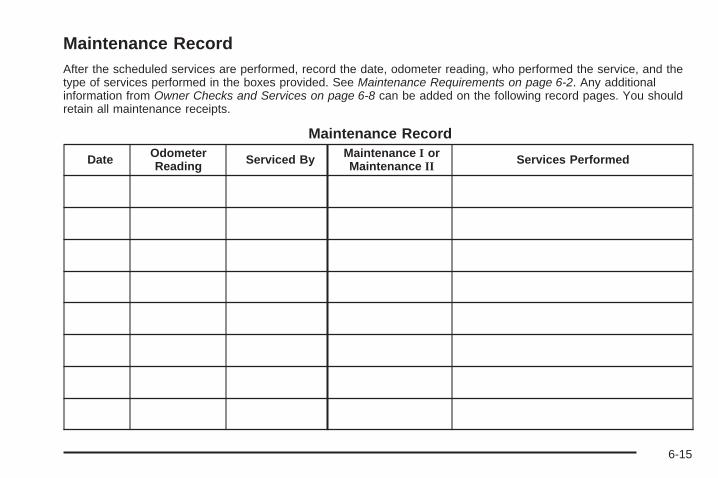
Maintenance RecordAfter the scheduled services are performed, record the date, odometer reading, who performed the service, and thetype of services performed in the boxes provided. See Maintenance Requirements on page 6-2. Any additionalinformation from Owner Checks and Services on page 6-8 can be added on the following record pages. You shouldretain all maintenance receipts.
Maintenance Record
Date OdometerReading Serviced By Maintenance I or
Maintenance II Services Performed
6-15
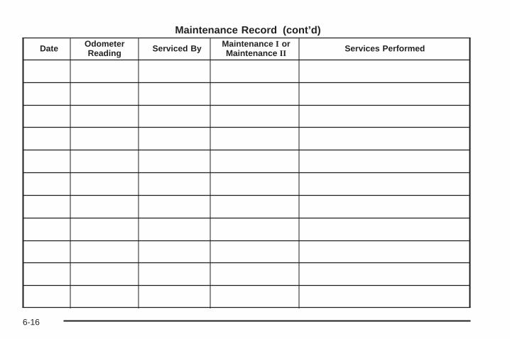
Maintenance Record (cont’d)
Date OdometerReading Serviced By Maintenance I or
Maintenance II Services Performed
6-16
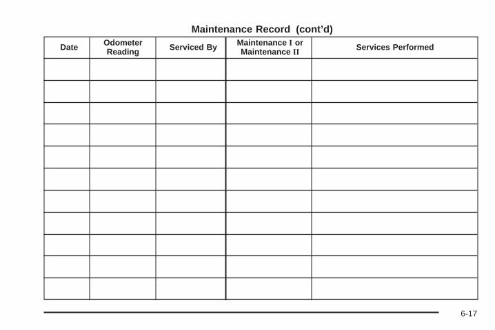
Maintenance Record (cont’d)
Date OdometerReading Serviced By Maintenance I or
Maintenance II Services Performed
6-17

Maintenance Record (cont’d)
Date OdometerReading Serviced By Maintenance I or
Maintenance II Services Performed
6-18
Customer Assistance and Information ...............7-2Customer Satisfaction Procedure ......................7-2Online Owner Center ......................................7-5Customer Assistance for
Text Telephone (TTY) Users .........................7-6Customer Assistance Offices ............................7-6GM Mobility Reimbursement Program ................7-7Roadside Assistance Program ..........................7-7Scheduling Service Appointments ....................7-10Courtesy Transportation .................................7-10Collision Damage Repair ................................7-11
Reporting Safety Defects ................................7-14Reporting Safety Defects to the
United States Government ..........................7-14Reporting Safety Defects to the
Canadian Government ................................7-15Reporting Safety Defects to General Motors .....7-15Service Publications Ordering Information .........7-15
Vehicle Data Recording and Privacy ................7-16Event Data Recorders ...................................7-17OnStar® ......................................................7-18Navigation System ........................................7-18Radio Frequency Identification (RFID) ..............7-18
Section 7 Customer Assistance Information
7-1
Customer Assistance andInformation
Customer Satisfaction ProcedureYour satisfaction and goodwill are important toyour dealer and to Chevrolet. Normally, any concernswith the sales transaction or the operation of the vehiclewill be resolved by the dealer’s sales or servicedepartments. Sometimes, however, despite the bestintentions of all concerned, misunderstandings canoccur. If your concern has not been resolved to yoursatisfaction, the following steps should be taken:
STEP ONE: Discuss your concern with a member ofdealership management. Normally, concerns canbe quickly resolved at that level. If the matter hasalready been reviewed with the sales, service, or partsmanager, contact the owner of the dealership or thegeneral manager.
STEP TWO: If after contacting a member of dealershipmanagement, it appears your concern cannot beresolved by the dealership without further help, in theU.S., call the Chevrolet Customer Assistance Center at1-800-222-1020. In Canada, call General Motors ofCanada Customer Communication Centre at1-800-263-3777 (English), or 1-800-263-7854 (French).
We encourage you to call the toll-free number inorder to give your inquiry prompt attention. Have thefollowing information available to give the CustomerAssistance Representative:
• Vehicle Identification Number (VIN). This isavailable from the vehicle registration or title, or theplate at the top left of the instrument panel andvisible through the windshield.
• Dealership name and location.
• Vehicle delivery date and present mileage.
When contacting Chevrolet, remember that yourconcern will likely be resolved at a dealer’s facility.That is why we suggest following Step One first.
7-2
STEP THREE — U.S. Owners: Both General Motorsand your dealer are committed to making sure youare completely satisfied with your new vehicle. However,if you continue to remain unsatisfied after followingthe procedure outlined in Steps One and Two, you canfile with the Better Business Bureau (BBB) Auto LineProgram to enforce your rights.
The BBB Auto Line Program is an out of court programadministered by the Council of Better Business Bureausto settle automotive disputes regarding vehicle repairs orthe interpretation of the New Vehicle Limited Warranty.Although you may be required to resort to this informaldispute resolution program prior to filing a court action,use of the program is free of charge and your case willgenerally be heard within 40 days. If you do not agreewith the decision given in your case, you may reject it andproceed with any other venue for relief available to you.
You may contact the BBB Auto Line Program using thetoll-free telephone number or write them at the followingaddress:
BBB Auto Line ProgramCouncil of Better Business Bureaus, Inc.4200 Wilson BoulevardSuite 800Arlington, VA 22203-1838
Telephone: 1-800-955-5100dr.bbb.org/goauto
This program is available in all 50 states and theDistrict of Columbia. Eligibility is limited by vehicle age,mileage, and other factors. General Motors reservesthe right to change eligibility limitations and/ordiscontinue its participation in this program.
7-3
STEP THREE — Canadian Owners: In the event thatyou do not feel your concerns have been addressed afterfollowing the procedure outlined in Steps 1 and 2,General Motors of Canada Limited wants you to be awareof its participation in a no-charge Mediation/ArbitrationProgram. General Motors of Canada Limited hascommitted to binding arbitration of owner disputesinvolving factory-related vehicle service claims. Theprogram provides for the review of the facts involved byan impartial third party arbiter, and may include aninformal hearing before the arbiter. The program isdesigned so that the entire dispute settlement process,from the time you file your complaint to the final decision,should be completed in about 70 days. We believe ourimpartial program offers advantages over courts in mostjurisdictions because it is informal, quick, and free ofcharge.
For further information concerning eligibility in theCanadian Motor Vehicle Arbitration Plan (CAMVAP), calltoll-free 1-800-207-0685, or call the General MotorsCustomer Communication Centre, 1-800-263-3777(English), 1-800-263-7854 (French), or write to:
The Mediation/Arbitration Programc/o Customer Communication CentreGeneral Motors of Canada LimitedMail Code: CA1-163-0051908 Colonel Sam DriveOshawa, Ontario L1H 8P7
Your inquiry should be accompanied by the VehicleIdentification Number (VIN).
7-4
Online Owner Center
(United States only)The Owner Center is a resource for your GM ownershipneeds. Specific vehicle information can be found inone place.
The Online Owner Center allows you to:
• Get e-mail service reminders.
• Access information about your specific vehicle,including tips and videos and an electronicversion of this owner manual.
• Keep track of your vehicle’s service history andmaintenance schedule.
• Find GM dealers/retailers for service nationwide.
• Receive special promotions and privileges onlyavailable to members.
Refer to MyGMLink.com on the web for updatedinformation and to register your vehicle.
My GM Canada (Canada only)My GM Canada is a password-protected section ofgmcanada.com where you can save information onGM vehicles, get personalized offers, and use handytools and forms with greater ease.
Here are a few of the valuable tools and services youwill have access to:
− My Showroom: Find and save information onvehicles and current offers in your area.
− My Dealers/Retailers: Save details such asaddress and phone number for each of yourpreferred GM Dealers or Retailers.
− My Driveway: Receive service reminders andhelpful advice on owning and maintainingyour vehicle.
− My Preferences: Manage your profile, subscribe toE-News and use tools and forms with greater ease.
To sign up to My GM Canada, visit the My GM Canadasection within gmcanada.com.
7-5
Customer Assistance for TextTelephone (TTY) UsersTo assist customers who are deaf, hard of hearing,or speech-impaired and who use Text Telephones(TTYs), Chevrolet has TTY equipment available atits Customer Assistance Center. Any TTY user inthe U.S. can communicate with Chevrolet by dialing:1-800-833-CHEV (2438). (TTY users in Canada candial 1-800-263-3830.)
Customer Assistance OfficesChevrolet encourages customers to call the toll-freenumber for assistance. However, if a customer wishesto write or e-mail Chevrolet, the letter should beaddressed to:
United States — Customer AssistanceChevrolet Motor DivisionChevrolet Customer Assistance CenterP.O. Box 33170Detroit, MI 48232-5170
Chevrolet.com1-800-222-10201-800-833-2438 (For Text Telephone devices (TTYs))Roadside Assistance: 1-800-CHEV-USA (243-8872)
From Puerto Rico:1-800-496-9992 (English)1-800-496-9993 (Spanish)
From U.S. Virgin Islands:1-800-496-9994
Canada — Customer AssistanceGeneral Motors of Canada LimitedCustomer Communication Centre, CA1-163-0051908 Colonel Sam DriveOshawa, Ontario L1H 8P7
gmcanada.com1-800-263-3777 (English)1-800-263-7854 (French)1-800-263-3830 (For Text Telephone devices (TTYs))Roadside Assistance: 1-800-268-6800
Overseas — Customer AssistancePlease contact the local General Motors Business Unit.
7-6
Mexico, Central America and CaribbeanIslands/Countries (Except Puerto Ricoand U.S. Virgin Islands) — CustomerAssistance
General Motors de Mexico, S. de R.L. de C.V.Customer Assistance CenterPaseo de la Reforma # 2740Col. Lomas de BezaresC.P. 11910, Mexico, D.F.01-800-508-0000Long Distance: 011-52-53 29 0 800
GM Mobility ReimbursementProgram
This program, available to qualified applicants, canreimburse you up to $1,000 of the cost of eligibleaftermarket adaptive equipment required for your vehicle,such as hand controls or a wheelchair/scooter lift.
The offer is available for a very limited period of timefrom the date of vehicle purchase/lease. For moredetails, or to determine your vehicle’s eligibility, visitgmmobility.com or call the GM Mobility AssistanceCenter at 1-800-323-9935. Text telephone (TTY) users,call 1-800-833-9935.
General Motors of Canada also has a Mobility Program.Call 1-800-GM-DRIVE (463-7483) for details.TTY users call 1-800-263-3830.
Roadside Assistance ProgramFor U.S. purchased vehicles, call 1-800-CHEV-USA(1-800-243-8872); (Text telephone (TTY):1-888-889-2438).
For Canadian purchased vehicles, call 1-800-268-6800.
Service is available 24 hours a day, 365 days a year.
7-7
Calling for AssistanceWhen calling Roadside Assistance, have the followinginformation ready:
• Your name, home address, and home telephonenumber
• Telephone number of your location
• Location of the vehicle
• Model, year, color, and license plate number of thevehicle
• Odometer reading, Vehicle Identification Number(VIN), and delivery date of the vehicle
• Description of the problem
CoverageServices are provided up to 5 years/100,000 miles(160 000 km), whichever comes first.
In the U.S., anyone driving the vehicle is covered.In Canada, a person driving the vehicle withoutpermission from the owner is not covered.
Roadside Assistance is not a part of the New VehicleLimited Warranty. Chevrolet and General Motors ofCanada Limited reserve the right to make any changesor discontinue the Roadside Assistance program atany time without notification.
Chevrolet and General Motors of Canada Limitedreserve the right to limit services or payment to an owneror driver if they decide the claims are made too often,or the same type of claim is made many times.
Services Provided• Emergency Fuel Delivery: Delivery of enough fuel
for the vehicle to get to the nearest service station.
• Lock-Out Service: Service is provided to unlock thevehicle if you are locked out. A remote unlock maybe available if you have OnStar®. For securityreasons, the driver must present identificationbefore this service is given.
• Emergency Tow From a Public Road orHighway: Tow to the nearest Chevrolet dealer forwarranty service, or if the vehicle was in a crashand cannot be driven. Assistance is also given whenthe vehicle is stuck in the sand, mud, or snow.
• Flat Tire Change: Service is provided to changea flat tire with the spare tire. The spare tire, ifequipped, must be in good condition and properlyinflated. It is the owner’s responsibility for the repairor replacement of the tire if it is not covered bythe warranty.
7-8
• Battery Jump Start: Service is provided to jumpstart a dead battery.
• Trip Interruption Benefits and Assistance: If yourtrip is interrupted due to a warranty failure, incidentalexpenses may be reimbursed during the 5 years/100,000 miles (160 000 km) Powertrain warrantyperiod. Items considered are hotel, meals, andrental car.
Services Not Included in RoadsideAssistance• Impound towing caused by violation of any laws.
• Legal fines.
• Mounting, dismounting or changing of snow tires,chains, or other traction devices.
• Towing or services for vehicles driven on anon-public road or highway.
Services Specific to CanadianPurchased Vehicles• Fuel delivery: Reimbursement is approximately
$5 Canadian. Diesel fuel delivery may be restricted.Propane and other fuels are not provided throughthis service.
• Lock-Out Service: Vehicle registration is required.
• Trip Routing Service: Detailed maps of NorthAmerica are provided when requested either withthe most direct route or the most scenic route. Thereis a limit of six requests per year. Additional travelinformation is also available. Allow three weeks fordelivery.
• Trip Interruption Benefits and Assistance: Mustbe over 250 kilometres from where your trip wasstarted to qualify. General Motors of Canada Limitedrequires pre-authorization, original detailed receipts,and a copy of the repair orders. Once authorizationhas been received, the Roadside Assistance advisorwill help you make arrangements and explain how toreceive payment.
• Alternative Service: If assistance cannot beprovided right away, the Roadside Assistanceadvisor may give you permission to get localemergency road service. You will receive payment,up to $100, after sending the original receipt toRoadside Assistance. Mechanical failures may becovered, however any cost for parts and labor forrepairs not covered by the warranty are the ownerresponsibility.
7-9
Scheduling Service AppointmentsWhen your vehicle requires warranty service, contactyour dealer/retailer and request an appointment.By scheduling a service appointment and advising yourservice consultant of your transportation needs, yourdealer/retailer can help minimize your inconvenience.
If your vehicle cannot be scheduled into the servicedepartment immediately, keep driving it until it can bescheduled for service, unless, of course, the problem issafety-related. If it is, please call your dealership/retailer,let them know this, and ask for instructions.
If the dealer/retailer requests you to bring the vehicle forservice, you are urged to do so as early in the workday as possible to allow for the same day repair.
Courtesy TransportationTo enhance your ownership experience, we and ourparticipating dealers are proud to offer CourtesyTransportation, a customer support program for vehicleswith the Bumper to Bumper (Base Warranty Coverageperiod in Canada) and extended powertrain warrantyin both the U.S. and Canada.
Several courtesy transportation options are available toassist in reducing your inconvenience when warrantyrepairs are required.
Courtesy Transportation is not a part of the New VehicleLimited Warranty. A separate booklet entitled “Warrantyand Owner Assistance Information” furnished with eachnew vehicle provides detailed warranty coverageinformation.
Transportation OptionsWarranty service can generally be completed while youwait. However, if you are unable to wait, GM helpsto minimize your inconvenience by providing severaltransportation options. Depending on the circumstances,your dealer can offer you one of the following:
Shuttle ServiceShuttle service is the preferred means of offeringCourtesy Transportation. Dealers may provide youwith shuttle service to get you to your destination withminimal interruption of your daily schedule. This includesone-way or round trip shuttle service within reasonabletime and distance parameters of the dealer’s area.
7-10
Public Transportation or FuelReimbursementIf your vehicle requires overnight warranty repairs, andpublic transportation is used instead of the dealer’sshuttle service, the expense must be supported byoriginal receipts and can only be up to the maximumamount allowed by GM for shuttle service. In addition,for U.S. customers, should you arrange transportationthrough a friend or relative, limited reimbursement forreasonable fuel expenses may be available. Claimamounts should reflect actual costs and be supportedby original receipts. See your dealer for informationregarding the allowance amounts for reimbursement offuel or other transportation costs.
Courtesy Rental VehicleYour dealer may arrange to provide you with a courtesyrental vehicle or reimburse you for a rental vehiclethat you obtain if your vehicle is kept for an overnightwarranty repair. Rental reimbursement will be limitedand must be supported by original receipts. Thisrequires that you sign and complete a rental agreementand meet state/provincial, local, and rental vehicleprovider requirements. Requirements vary and mayinclude minimum age requirements, insurance coverage,credit card, etc. You are responsible for fuel usage
charges and may also be responsible for taxes,levies, usage fees, excessive mileage, or rentalusage beyond the completion of the repair.
It may not be possible to provide a like-vehicle as acourtesy rental.
Additional Program InformationAll program options, such as shuttle service, may not beavailable at every dealer. Please contact your dealerfor specific information about availability. All CourtesyTransportation arrangements will be administeredby appropriate dealer personnel.
General Motors reserves the right to unilaterally modify,change or discontinue Courtesy Transportation atany time and to resolve all questions of claim eligibilitypursuant to the terms and conditions describedherein at its sole discretion.
Collision Damage RepairIf your vehicle is involved in a collision and it isdamaged, have the damage repaired by a qualifiedtechnician using the proper equipment and qualityreplacement parts. Poorly performed collision repairsdiminish your vehicle’s resale value, and safetyperformance can be compromised in subsequentcollisions.
7-11
Collision PartsGenuine GM Collision parts are new parts made with thesame materials and construction methods as the partswith which your vehicle was originally built. Genuine GMCollision parts are your best choice to ensure that yourvehicle’s designed appearance, durability, and safety arepreserved. The use of Genuine GM parts can helpmaintain your GM New Vehicle Warranty.
Recycled original equipment parts may also be used forrepair. These parts are typically removed from vehiclesthat were total losses in prior crashes. In most cases,the parts being recycled are from undamaged sectionsof the vehicle. A recycled original equipment GMpart, may be an acceptable choice to maintain yourvehicle’s originally designed appearance and safetyperformance, however, the history of these parts is notknown. Such parts are not covered by your GM NewVehicle Limited Warranty, and any related failuresare not covered by that warranty.
Aftermarket collision parts are also available. Theseare made by companies other than GM and maynot have been tested for your vehicle. As a result,these parts may fit poorly, exhibit prematuredurability/corrosion problems, and may not performproperly in subsequent collisions. Aftermarket partsare not covered by your GM New Vehicle LimitedWarranty, and any vehicle failure related to suchparts are not covered by that warranty.
Repair FacilityWe recommend that you choose a collision repair facilitythat meets your needs before you ever need collisionrepairs. Your dealer/retailer may have a collision repaircenter with GM-trained technicians and state of the artequipment, or be able to recommend a collision repaircenter that has GM-trained technicians and comparableequipment.
Insuring Your VehicleProtect your investment in your GM vehicle withcomprehensive and collision insurance coverage.There are significant differences in the quality ofcoverage afforded by various insurance policy terms.Many insurance policies provide reduced protection toyour GM vehicle by limiting compensation for damagerepairs by using aftermarket collision parts. Someinsurance companies will not specify aftermarket collisionparts. When purchasing insurance, we recommend thatyou assure your vehicle will be repaired with GM originalequipment collision parts. If such insurance coverage isnot available from your current insurance carrier,consider switching to another insurance carrier.If your vehicle is leased, the leasing company mayrequire you to have insurance that assures repairs withGenuine GM Original Equipment Manufacturer (OEM)parts or Genuine Manufacturer replacement parts. Readyour lease carefully, as you may be charged at the end ofyour lease for poor quality repairs.
7-12

If a Crash OccursHere is what to do if you are involved in a crash.
• Check to make sure that you are all right. If you areuninjured, make sure that no one else in yourvehicle, or the other vehicle, is injured.
• If there has been an injury, call emergency servicesfor help. Do not leave the scene of a crash untilall matters have been taken care of. Moveyour vehicle only if its position puts you in dangeror you are instructed to move it by a police officer.
• Give only the necessary and requested informationto police and other parties involved in the crash.Do not discuss your personal condition, mentalframe of mind, or anything unrelated to the crash.This will help guard against post-crash legal action.
• If you need roadside assistance, call GM RoadsideAssistance. See Roadside Assistance Program onpage 7-7 for more information.
• If your vehicle cannot be driven, know where thetowing service will be taking it. Get a card fromthe tow truck operator or write down the driver’sname, the service’s name, and the phone number.
• Remove any valuables from your vehicle before it istowed away. Make sure this includes your insuranceinformation and registration if you keep theseitems in your vehicle.
• Gather the important information you will need fromthe other driver. Things like name, address, phonenumber, driver’s license number, vehicle licenseplate, vehicle make, model and model year, VehicleIdentification Number (VIN), insurance companyand policy number, and a general description of thedamage to the other vehicle.
• If possible, call your insurance company from thescene of the crash. They will walk you through theinformation they will need. If they ask for a policereport, phone or go to the police departmentheadquarters the next day and you can get a copy ofthe report for a nominal fee. In some states/provinceswith “no fault” insurance laws, a report may not benecessary. This is especially true if there are noinjuries and both vehicles are drivable.
• Choose a reputable collision repair facility for yourvehicle. Whether you select a dealer/retailer or aprivate collision repair facility to fix the damage,make sure you are comfortable with them.Remember, you will have to feel comfortable withtheir work for a long time.
• Once you have an estimate, read it carefully andmake sure you understand what work will beperformed on your vehicle. If you have a question,ask for an explanation. Reputable shops welcomethis opportunity.
7-13
Managing the Vehicle Damage RepairProcessIn the event that your vehicle requires damage repairs,GM recommends that you take an active role in itsrepair. If you have a pre-determined repair facility ofchoice, take your vehicle there, or have it towed there.Specify to the facility that any required replacementcollision parts be original equipment parts, either newGenuine GM parts or recycled original GM parts.Remember, recycled parts will not be covered byyour GM vehicle warranty.
Insurance pays the bill for the repair, but you mustlive with the repair. Depending on your policy limits,your insurance company may initially value the repairusing aftermarket parts. Discuss this with your repairprofessional, and insist on Genuine GM parts. Rememberif your vehicle is leased you may be obligated to have thevehicle repaired with Genuine GM parts, even if yourinsurance coverage does not pay the full cost.
If another party’s insurance company is paying forthe repairs, you are not obligated to accept a repairvaluation based on that insurance company’s collisionpolicy repair limits, as you have no contractual limits withthat company. In such cases, you can have control ofthe repair and parts choices as long as cost stays withinreasonable limits.
Reporting Safety Defects
Reporting Safety Defects to theUnited States GovernmentIf you believe that your vehicle has a defect whichcould cause a crash or could cause injury ordeath, you should immediately inform the NationalHighway Traffic Safety Administration (NHTSA)in addition to notifying General Motors.
If NHTSA receives similar complaints, it may openan investigation, and if it finds that a safety defectexists in a group of vehicles, it may order a recalland remedy campaign. However, NHTSA cannotbecome involved in individual problems betweenyou, your dealer/retailer, or General Motors.
To contact NHTSA, you may call the VehicleSafety Hotline toll-free at 1-888-327-4236(TTY: 1-800-424-9153); go tohttp://www.safercar.gov; or write to:
Administrator, NHTSA1200 New Jersey Avenue, S.E.Washington D.C., 20590
You can also obtain other information about motorvehicle safety from http://www.safercar.gov.
7-14
Reporting Safety Defects to theCanadian GovernmentIf you live in Canada, and you believe that yourvehicle has a safety defect, notify Transport Canadaimmediately, in addition to notifying General Motors ofCanada Limited. Call them at 1-800-333-0510 or write to:
Transport CanadaRoad Safety Branch2780 Sheffield RoadOttawa, Ontario K1B 3V9
Reporting Safety Defects toGeneral MotorsIn addition to notifying NHTSA (or Transport Canada) ina situation like this, please notify General Motors.
Call 1-800-222-1020, or write:Chevrolet Motor DivisionChevrolet Customer Assistance CenterP.O. Box 33170Detroit, MI 48232-5170
In Canada, call 1-800-263-3777 (English) or1-800-263-7854 (French), or write:
General Motors of Canada LimitedCustomer Communication Centre, CA1-163-0051908 Colonel Sam DriveOshawa, Ontario L1H 8P7
Service Publications OrderingInformation
Service ManualsService Manuals have the diagnosis and repairinformation on engines, transmission, axle suspension,brakes, electrical, steering, body, etc.
Service BulletinsService Bulletins give additional technical serviceinformation needed to knowledgeably serviceGeneral Motors cars and trucks. Each bulletin containsinstructions to assist in the diagnosis and service ofyour vehicle.
Owner InformationOwner publications are written specifically for ownersand intended to provide basic operational informationabout the vehicle. The owner manual includes theMaintenance Schedule for all models.
In-Portfolio: Includes a Portfolio, Owner Manual, andWarranty Booklet.
RETAIL SELL PRICE: $35.00 (U.S.) plus processing fee
Without Portfolio: Owner Manual only.
RETAIL SELL PRICE: $25.00 (U.S.) plus processing fee
7-15
Current and Past Model Order FormsTechnical Service Bulletins and Manuals are availablefor current and past model GM vehicles. To requestan order form, specify year and model name ofthe vehicle.
ORDER TOLL FREE: 1-800-551-4123Monday-Friday 8:00 AM - 6:00 PMEastern TimeFor Credit Card Orders Only(VISA-MasterCard-Discover), visit Helm, Inc. on theWorld Wide Web at: helminc.com
Or you can write to:
Helm, IncorporatedP.O. Box 07130Detroit, MI 48207
Prices are subject to change without notice and withoutincurring obligation. Allow ample time for delivery.
Note to Canadian Customers: All listed prices arequoted in U.S. funds. Canadian residents are to makechecks payable in U.S. funds.
Vehicle Data Recording andPrivacyYour GM vehicle has a number of sophisticatedcomputers that record information about the vehicle’sperformance and how it is driven. For example, yourvehicle uses computer modules to monitor and controlengine and transmission performance, to monitor theconditions for airbag deployment and deploy airbags in acrash and, if so equipped, to provide antilock braking tohelp the driver control the vehicle. These modules maystore data to help your dealer/retailer technician serviceyour vehicle. Some modules may also store data abouthow you operate the vehicle, such as rate of fuelconsumption or average speed. These modules may alsoretain the owner’s personal preferences, such as radiopre-sets, seat positions, and temperature settings.
7-16
Event Data RecordersThis vehicle has an Event Data Recorder (EDR).The main purpose of an EDR is to record, in certaincrash or near crash-like situations, such as an airbagdeployment or hitting a road obstacle, data that willassist in understanding how a vehicle’s systemsperformed. The EDR is designed to record data relatedto vehicle dynamics and safety systems for a shortperiod of time, typically 30 seconds or less. The EDRin this vehicle is designed to record such data as:
• How various systems in your vehicle were operating
• Whether or not the driver and passenger safetybelts were buckled/fastened
• How far, if at all, the driver was pressing theaccelerator and/or brake pedal
• How fast the vehicle was traveling
This data can help provide a better understanding of thecircumstances in which crashes and injuries occur.
Important: EDR data is recorded by your vehicleonly if a non-trivial crash situation occurs; no data isrecorded by the EDR under normal driving conditionsand no personal data (e.g., name, gender, age,and crash location) is recorded. However, other parties,such as law enforcement, could combine the EDRdata with the type of personally identifying data routinelyacquired during a crash investigation.
To read data recorded by an EDR, special equipment isrequired, and access to the vehicle or the EDR isneeded. In addition to the vehicle manufacturer, otherparties, such as law enforcement, that have the specialequipment, can read the information if they haveaccess to the vehicle or the EDR.
GM will not access this data or share it with othersexcept: with the consent of the vehicle owner or, if thevehicle is leased, with the consent of the lessee; inresponse to an official request of police or similargovernment office; as part of GM’s defense of litigationthrough the discovery process; or, as required by law.Data that GM collects or receives may also be used forGM research needs or may be made available to othersfor research purposes, where a need is shown and thedata is not tied to a specific vehicle or vehicle owner.
7-17
OnStar®
If your vehicle has OnStar and you subscribe to theOnStar services, please refer to the OnStar Terms andConditions for information on data collection anduse. See also OnStar® System on page 2-47 in thismanual for more information.
Navigation SystemIf your vehicle has a navigation system, use of thesystem may result in the storage of destinations,addresses, telephone numbers, and other tripinformation. Refer to the navigation system operatingmanual for information on stored data and for deletioninstructions.
Radio FrequencyIdentification (RFID)RFID technology is used in some vehicles for functionssuch as tire pressure monitoring and ignition systemsecurity, as well as in connection with conveniencessuch as key fobs for remote door locking/unlocking andstarting, and in-vehicle transmitters for garage dooropeners. RFID technology in GM vehicles does not useor record personal information or link with any otherGM system containing personal information.
7-18
AAccessories and Modifications ............................ 5-3Accessory Power Outlets ................................. 3-20Adding Equipment to Your Airbag-Equipped
Vehicle ....................................................... 1-91Additives, Fuel ................................................. 5-7Add-On Electrical Equipment ............................ 5-97Air Cleaner/Filter, Engine ................................. 5-20Air Conditioning ...................................... 3-22, 3-25Airbag
Passenger Status Indicator ........................... 3-34Readiness Light .......................................... 3-33
Airbag System ................................................ 1-77Adding Equipment to Your Airbag-Equipped
Vehicle ................................................... 1-91How Does an Airbag Restrain? ...................... 1-83Passenger Sensing System ........................... 1-85Servicing Your Airbag-Equipped Vehicle .......... 1-90What Makes an Airbag Inflate? ...................... 1-83What Will You See After an Airbag Inflates? .... 1-84When Should an Airbag Inflate? .................... 1-82Where Are the Airbags? ............................... 1-80
Antenna, Fixed Mast ...................................... 3-113Antenna, XM™ Satellite Radio Antenna
System ..................................................... 3-113Antilock Brake System (ABS) ............................. 4-5Anti-lock Brake, System Warning Light ............... 3-36
Appearance CareAluminum Wheels ........................................ 5-95Care of Safety Belts and Built-in Child
Restraint Harness ..................................... 5-92Chemical Paint Spotting ............................... 5-96Child Restraint Pad ...................................... 5-92Cleaning Exterior Lamps/Lenses .................... 5-93Fabric/Carpet .............................................. 5-91Finish Care ................................................. 5-94Finish Damage ............................................ 5-96Instrument Panel, Vinyl, and Other Plastic
Surfaces ................................................. 5-92Interior Cleaning .......................................... 5-89Leather ...................................................... 5-91Sheet Metal Damage ................................... 5-96Tires .......................................................... 5-95Underbody Maintenance ............................... 5-96Washing Your Vehicle ................................... 5-93Weatherstrips .............................................. 5-92Windshield, Backglass, and Wiper Blades ....... 5-94
Appointments, Scheduling Service ..................... 7-10Audio System ................................................. 3-76
Audio Steering Wheel Controls .................... 3-111Chime Level Adjustment ............................. 3-113Fixed Mast Antenna ................................... 3-113Radio Reception ........................................ 3-112Rear Seat Audio (RSA) ............................... 3-108Setting the Clock ......................................... 3-77
1
Audio System (cont.)Theft-Deterrent Feature ............................... 3-110XM™ Satellite Radio Antenna System ........... 3-113
Audio System(s) ............................................. 3-77Automatic Door Lock ....................................... 2-12Automatic Transmission
Fluid .......................................................... 5-21Operation ................................................... 2-35
BBattery .......................................................... 5-36
Electric Power Management .......................... 3-18Run-Down Protection ................................... 3-19
BrakeEmergencies ................................................ 4-6
Brakes .......................................................... 5-33System Warning Light .................................. 3-35
Braking ........................................................... 4-4Braking in Emergencies ..................................... 4-6Break-In, New Vehicle ..................................... 2-31Bucket Seats, Rear ........................................... 1-7Built-in Child Restraint ..................................... 1-67Bulb Replacement ........................................... 5-41
Front Turn Signal, Parking and DaytimeRunning Lamps ........................................ 5-43
Halogen Bulbs ............................................ 5-41Headlamp Aiming ........................................ 5-41
Bulb Replacement (cont.)License Plate Lamps .................................... 5-45Replacement Bulbs ...................................... 5-45Taillamps, Turn Signal, Stoplamps and
Back-up Lamps ........................................ 5-44Buying New Tires ........................................... 5-64
CCalibration ..................................................... 3-49California Fuel .................................................. 5-6California Perchlorate Materials Requirements ....... 5-4California Proposition 65 Warning ....................... 5-4Canadian Owners ................................................ iiCapacities and Specifications .......................... 5-104Captain Chairs, Rear ....................................... 1-14Carbon Monoxide ................................... 2-41, 4-16Care of
Safety Belts and Built-in Child RestraintHarness .................................................. 5-92
Cargo Lamp ................................................... 3-17CD, MP3 ....................................................... 3-89Chains, Tire ................................................... 5-70Charging System Light .................................... 3-35Check
Engine Light ............................................... 3-38Checking Things Under the Hood ...................... 5-12Chemical Paint Spotting ................................... 5-96
2
Child RestraintsBuilt-In Child Restraint .................................. 1-67Child Restraint Systems ............................... 1-49Infants and Young Children ........................... 1-46Lower Anchors and Tethers for Children .......... 1-53Older Children ............................................. 1-43Securing a Child Restraint in a
Rear Seat Position ................................... 1-60Securing a Child Restraint in the
Right Front Seat Position .......................... 1-62Where to Put the Restraint ........................... 1-51
Chime Level Adjustment ................................. 3-113Cigarette Lighter ............................................. 3-22Cleaning
Aluminum Wheels ........................................ 5-95Child Restraint Pad ...................................... 5-92Exterior Lamps/Lenses ................................. 5-93Fabric/Carpet .............................................. 5-91Finish Care ................................................. 5-94Instrument Panel, Vinyl, and Other
Plastic Surfaces ....................................... 5-92Interior ....................................................... 5-89Leather ...................................................... 5-91Tires .......................................................... 5-95Underbody Maintenance ............................... 5-96Washing Your Vehicle ................................... 5-93Weatherstrips .............................................. 5-92Windshield, Backglass, and Wiper Blades ....... 5-94
Climate Control System ................................... 3-22Air Filter, Passenger Compartment ................. 3-29Dual .......................................................... 3-25Outlet Adjustment ........................................ 3-27Rear .......................................................... 3-28
Clock, Setting ................................................. 3-77Collision Damage Repair .................................. 7-11Compact Spare Tire ........................................ 5-88Compass ....................................................... 3-49Content Theft-Deterrent .................................... 2-27Control of a Vehicle .......................................... 4-3Convenience Center ........................................ 2-61Convenience Net ............................................ 2-60Coolant
Engine ....................................................... 5-24Engine Temperature Gage ............................ 3-37
Cooling System .............................................. 5-23Cruise Control ................................................ 3-10Cruise Control Light ........................................ 3-42Cupholders .................................................... 2-55Customer Assistance Information
Courtesy Transportation ................................ 7-10Customer Assistance for
Text Telephone (TTY) Users ........................ 7-6Customer Assistance Offices ........................... 7-6Customer Satisfaction Procedure ..................... 7-2GM Mobility Reimbursement Program ............... 7-7Reporting Safety Defects to General Motors ..... 7-15
3
Customer Assistance Information (cont.)Reporting Safety Defects to the
Canadian Government .............................. 7-15Reporting Safety Defects to the
United States Government ......................... 7-14Roadside Assistance Program ......................... 7-7Service Publications Ordering Information ........ 7-15
DDaytime Running Lamps/Automatic
Headlamp System ....................................... 3-14Defensive Driving ............................................. 4-2Delayed Lighting ............................................. 3-16Delayed Locking ............................................. 2-12DIC Compass ................................................. 3-49Disc, MP3 ...................................................... 3-89Doing Your Own Service Work ........................... 5-4Dome Lamp ................................................... 3-16Door
Automatic Door Lock .................................... 2-12Delayed Locking .......................................... 2-12Dual Sliding Doors ....................................... 2-13Locks ........................................................ 2-10Power Door Locks ....................................... 2-11Power Sliding Door ...................................... 2-16Programmable Automatic Door Unlock ............ 2-13
Driver Information Center (DIC) ......................... 3-43DIC Operation and Displays .......................... 3-44DIC Vehicle Personalization .......................... 3-68DIC Warnings and Messages ........................ 3-51
DrivingAt Night ..................................................... 4-12Before a Long Trip ...................................... 4-14Defensive ..................................................... 4-2Drunken ....................................................... 4-2Highway Hypnosis ....................................... 4-14Hill and Mountain Roads .............................. 4-15In Rain and on Wet Roads ........................... 4-13Rocking Your Vehicle to Get it Out ................. 4-18Winter ........................................................ 4-16
Dual Climate Control System ............................ 3-25DVD
Rear Seat Entertainment System ................... 3-93
EEDR ............................................................. 7-16Electrical System
Add-On Equipment ...................................... 5-97Fuses and Circuit Breakers ........................... 5-98Headlamp Wiring ......................................... 5-98Instrument Panel Fuse Block ......................... 5-98Power Windows and Other Power Options ...... 5-98
4
Electrical System (cont.)Underhood Fuse Block ............................... 5-100Windshield Wiper Fuses ............................... 5-98
Electronic ImmobilizerPASS-Key® III+ ........................................... 2-29
Electronic Immobilizer OperationPASS-Key® III ............................................. 2-29
EngineAir Cleaner/Filter ......................................... 5-20Check and Service Engine Soon Light ............ 3-38Coolant ...................................................... 5-24Coolant Heater ............................................ 2-34Coolant Temperature Gage ........................... 3-37Drive Belt Routing ....................................... 6-14Engine Compartment Overview ...................... 5-14Exhaust ..................................................... 2-41Oil ............................................................. 5-15Oil Life System ........................................... 5-18Overheated Protection Operating Mode ........... 5-30Overheating ................................................ 5-28Starting ...................................................... 2-32
Entry Lighting ................................................. 3-16Event Data Recorders ..................................... 7-17Exit Lighting ................................................... 3-17Extender, Safety Belt ....................................... 1-42Exterior Lamps ............................................... 3-13
FFilter
Engine Air Cleaner ...................................... 5-20Finish Damage ............................................... 5-96Fixed Mast Antenna ....................................... 3-113Flashers, Hazard Warning .................................. 3-6Flash-to-Pass ................................................... 3-8Flat Tire ........................................................ 5-73Flat Tire, Changing ......................................... 5-74Flat Tire, Storing ............................................. 5-86Fluid
Automatic Transmission ................................ 5-21Power Steering ........................................... 5-31Windshield Washer ...................................... 5-32
Folding Tray ................................................... 2-58Front Console Storage Area ............................. 2-58Front Reading Lamps ...................................... 3-17Front Turn Signal, Parking and Daytime
Running Lamps ........................................... 5-43Fuel ............................................................... 5-5
Additives ...................................................... 5-7California Fuel .............................................. 5-6E85 (85% Ethanol) ........................................ 5-8Filling a Portable Fuel Container .................... 5-12Filling the Tank ........................................... 5-10
5
Fuel (cont.)Fuels in Foreign Countries .............................. 5-9Gage ......................................................... 3-42Gasoline Octane ........................................... 5-6Gasoline Specifications .................................. 5-6Low Warning Light ....................................... 3-43
FusesFuses and Circuit Breakers ........................... 5-98Instrument Panel Fuse Block ......................... 5-98Underhood Fuse Block ............................... 5-100Windshield Wiper ......................................... 5-98
GGage
Engine Coolant Temperature ......................... 3-37Fuel .......................................................... 3-42Speedometer .............................................. 3-32Tachometer ................................................. 3-32
Garage Door Opener ....................................... 2-50Gasoline
Octane ........................................................ 5-6Specifications ............................................... 5-6
Glove Box ..................................................... 2-55GM Mobility Reimbursement Program .................. 7-7
HHazard Warning Flashers ................................... 3-6Head Restraints ............................................... 1-6Headlamp
Aiming ....................................................... 5-41Headlamp Wiring ............................................ 5-98Headlamps
Bulb Replacement ....................................... 5-41Daytime Running Lamps/Automatic
Headlamp System .................................... 3-14Exterior Lamps ............................................ 3-13Flash-to-Pass ............................................... 3-8Halogen Bulbs ............................................ 5-41Headlamps and Sidemarker Lamps ................ 5-42High/Low Beam Changer ................................ 3-8Wiper Activated ........................................... 3-14
Headlamps and Sidemarker Lamps ................... 5-42Heated Seats ................................................... 1-3Heater ................................................... 3-22, 3-25
Engine Coolant ........................................... 2-34Highbeam On Light ......................................... 3-42High-Speed Operation, Tires ............................. 5-56Highway Hypnosis ........................................... 4-14Hill and Mountain Roads .................................. 4-15Hood
Checking Things Under ................................ 5-12Release ..................................................... 5-13
Horn ............................................................... 3-6How to Wear Safety Belts Properly ................... 1-28
6
IIgnition Positions ............................................. 2-31Infants and Young Children, Restraints ............... 1-46Inflation - Tire Pressure ................................... 5-54Instrument Panel
Brightness .................................................. 3-15Cluster ....................................................... 3-31Overview ..................................................... 3-4
Interior LampsControl ....................................................... 3-15
JJump Starting ................................................. 5-37
KKeyless Entry System ....................................... 2-4Keys ............................................................... 2-3
LLabeling, Tire Sidewall ..................................... 5-48Lamps
Cargo ........................................................ 3-17Dome ........................................................ 3-16Front Reading ............................................. 3-17Rear Reading ............................................. 3-17
Lap-Shoulder Belt ........................................... 1-37LATCH System
Child Restraints ........................................... 1-53Level Control .................................................. 4-25License Plate Lamps ....................................... 5-45Liftgate
Carbon Monoxide ........................................ 2-22Light
Airbag Readiness ........................................ 3-33Anti-lock Brake System (ABS) Warning ........... 3-36Brake System Warning ................................. 3-35Charging System ......................................... 3-35Cruise Control ............................................. 3-42Highbeam On ............................................. 3-42Low Fuel Warning ....................................... 3-43
7
Light (cont.)Malfunction Indicator .................................... 3-38Oil Pressure ............................................... 3-41Passenger Airbag Status Indicator .................. 3-34Safety Belt Reminders .................................. 3-32Security ..................................................... 3-41TCS Warning Light ...................................... 3-37Tire Pressure .............................................. 3-38Traction Control System (TCS) Warning .......... 3-37
LightingDelayed ..................................................... 3-16Entry ......................................................... 3-16Exit ........................................................... 3-17
LightsExterior Lamps ............................................ 3-13Flash-to-Pass ............................................... 3-8High/Low Beam Changer ................................ 3-8
Loading Your Vehicle ....................................... 4-19Lockout Protection .......................................... 2-13Locks
Automatic Door Lock .................................... 2-12Delayed Locking .......................................... 2-12Door .......................................................... 2-10Lockout Protection ....................................... 2-13Power Door ................................................ 2-11Programmable Automatic Door Unlock ............ 2-13
Loss of Control ............................................... 4-11Low Fuel Warning Light ................................... 3-43Luggage Carrier .............................................. 2-59
MMaintenance Schedule
Additional Required Services ........................... 6-6At Each Fuel Fill ........................................... 6-8At Least Once a Month .................................. 6-9At Least Once a Year .................................... 6-9Introduction .................................................. 6-2Maintenance Footnotes .................................. 6-7Maintenance Record .................................... 6-15Maintenance Replacement Parts .................... 6-13Maintenance Requirements ............................. 6-2Owner Checks and Services ........................... 6-8Recommended Fluids and Lubricants ............. 6-11Scheduled Maintenance ................................. 6-4Using .......................................................... 6-3Your Vehicle and the Environment ................... 6-2
Malfunction Indicator Light ................................ 3-38Manual Rear Quarter Windows ......................... 2-26Manual Seats ................................................... 1-2Message
DIC Warnings and Messages ........................ 3-51Mirrors
Manual Rearview Mirror ................................ 2-43Outside Convex Mirror ................................. 2-43Outside Heated Mirrors ................................ 2-44Outside Power Mirrors .................................. 2-43
MP3 ............................................................. 3-89MyGMLink.com ................................................ 7-5
8
NNavigation System, Privacy .............................. 7-18New Vehicle Break-In ...................................... 2-31
OOdometer ...................................................... 3-32Odometer, Trip ............................................... 3-32Off-Road Recovery .......................................... 4-11Oil
Engine ....................................................... 5-15Pressure Light ............................................. 3-41
Oil, Engine Oil Life System .............................. 5-18Older Children, Restraints ................................ 1-43Online Owner Center ........................................ 7-5OnStar, Privacy .............................................. 7-18OnStar® System, see OnStar® Manual ............... 2-47Operation, Universal Home Remote System ........ 2-51Other Warning Devices ...................................... 3-6Outlet Adjustment ............................................ 3-27Outlets
Accessory Power ......................................... 3-20Outside
Convex Mirror ............................................. 2-43Heated Mirrors ............................................ 2-44Power Mirrors ............................................. 2-43
Overhead Console .................................. 2-55, 2-56Overhead Console Switchbank .......................... 3-19
Overheated Engine Protection Operating Mode .... 5-30Owner Checks and Services .............................. 6-8Owners, Canadian ............................................... ii
PPaint, Damage ............................................... 5-96Park
Shifting Into ................................................ 2-38Shifting Out of ............................................ 2-40
Park Aid ........................................................ 2-44Park Brake .................................................... 2-38Parking
Assist ........................................................ 2-44Over Things That Burn ................................. 2-40
Passenger Airbag Status Indicator ..................... 3-34Passenger Compartment Air Filter ..................... 3-29Passenger Sensing System .............................. 1-85Passing ......................................................... 4-11PASS-KEY® III+ Electronic Immobilizer ............... 2-29PASS-Key® III Electronic Immobilizer Operation ... 2-29Perchlorate Materials Requirements, California ...... 5-4Power
Door Locks ................................................. 2-11Electrical System ......................................... 5-98Outlet 115 Volt Alternating Current ................. 3-21Rear Quarter Windows ................................. 2-26Retained Accessory (RAP) ............................ 2-32Seat ............................................................ 1-3
9
Power (cont.)Sliding Door ................................................ 2-16Steering Fluid ............................................. 5-31Windows .................................................... 2-25
Privacy .......................................................... 7-16Event Data Recorders .................................. 7-17Navigation System ....................................... 7-18OnStar ....................................................... 7-18Radio Frequency Identification ....................... 7-18
Programmable Automatic Door Unlock ............... 2-13
RRadiator Pressure Cap .................................... 5-28Radio Frequency Identification (RFID), Privacy .... 7-18Radio(s) ........................................................ 3-77Radios
Rear Seat Audio ........................................ 3-108Reception ................................................. 3-112Setting the Clock ......................................... 3-77Theft-Deterrent .......................................... 3-110
Rear Climate Control System ............................ 3-28Rear Reading Lamps ...................................... 3-17Rear Seat Audio (RSA) .................................. 3-108Rear Seat Entertainment System ....................... 3-93Rear Seat Operation ......................................... 1-6Rear Windshield Washer/Wiper ........................... 3-9
Rearview Mirrors ............................................. 2-43Reclining Seatbacks .......................................... 1-4Recommended Fluids and Lubricants ................. 6-11Recreational Vehicle Towing ............................. 4-24Remote Keyless Entry (RKE) System .................. 2-4Remote Keyless Entry (RKE) System, Operation ... 2-5Remote Vehicle Start ........................................ 2-7Removing the Flat Tire and Installing the
Spare Tire .................................................. 5-77Removing the Spare Tire and Tools ................... 5-75Replacement Bulbs ......................................... 5-45Replacement Parts, Maintenance ...................... 6-13Reporting Safety Defects
Canadian Government .................................. 7-15General Motors ........................................... 7-15United States Government ............................ 7-14
Restraint System CheckChecking the Restraint Systems .................... 1-92Replacing Restraint System Parts
After a Crash .......................................... 1-93Retained Accessory Power (RAP) ...................... 2-32Roadside
Assistance Program ....................................... 7-7Rocking Your Vehicle to Get it Out .................... 4-18Routing, Engine Drive Belt ............................... 6-14Running the Vehicle While Parked ..................... 2-42
10
SSafety Belts
Care of Safety Belts and Built-in ChildRestraint Harness ..................................... 5-92
How to Wear Safety Belts Properly ................ 1-28Lap-Shoulder Belt ........................................ 1-37Reminder Light ............................................ 3-32Safety Belt Extender .................................... 1-42Safety Belt Use During Pregnancy ................. 1-42Safety Belts Are for Everyone ....................... 1-23
Safety Warnings and Symbols .............................. iiiScheduled Maintenance ..................................... 6-4Seats
Bucket Seats, Rear ....................................... 1-7Captain Chairs ............................................ 1-14Head Restraints ............................................ 1-6Heated Seats ............................................... 1-3Power Seats ................................................. 1-3Rear Seat Operation ...................................... 1-6Reclining Seatbacks ...................................... 1-4Third Row Seat ........................................... 1-18
Second Row Center Console ............................ 2-58Secondary Latch System ................................. 5-84Securing a Child Restraint
Rear Seat Position ...................................... 1-60Right Front Seat Position .............................. 1-62
Security Light ................................................. 3-41
Service ........................................................... 5-3Accessories and Modifications ......................... 5-3Adding Equipment to the Outside of the
Vehicle ..................................................... 5-5California Perchlorate Materials Requirements .... 5-4California Proposition 65 Warning .................... 5-4Doing Your Own Work ................................... 5-4Engine Soon Light ....................................... 3-38Publications Ordering Information ................... 7-15
Service, Scheduling Appointments ..................... 7-10Servicing Your Airbag-Equipped Vehicle .............. 1-90Setting the Clock ............................................ 3-77Sheet Metal Damage ....................................... 5-96Shifting Into Park ............................................ 2-38Shifting Out of Park ........................................ 2-40Signals, Turn and Lane-Change .......................... 3-7Sliding Door, Power ........................................ 2-16Sliding Doors, Dual ......................................... 2-13Spare Tire
Compact .................................................... 5-88Installing .................................................... 5-77Removing ................................................... 5-75Storing ....................................................... 5-86
Specifications, Capacities ............................... 5-104Speedometer .................................................. 3-32Stabilitrak® System ........................................... 4-7Start Vehicle, Remote ....................................... 2-7Starting the Engine ......................................... 2-32Steering .......................................................... 4-9
11
Steering Wheel Controls, Audio ....................... 3-111Steering Wheel, Tilt Wheel ................................. 3-6Storage Areas ................................................ 2-55
Convenience Center ..................................... 2-61Convenience Net ......................................... 2-60Cupholders ................................................. 2-55Floor Console Storage Area .......................... 2-58Folding Tray ............................................... 2-58Glove Box .................................................. 2-55Luggage Carrier .......................................... 2-59Overhead Console ............................... 2-55, 2-56Second Row Center Console ........................ 2-58
Stuck in Sand, Mud, Ice, or Snow ..................... 4-18Sun Visors ..................................................... 2-27Switchbanks
Overhead Console ....................................... 3-19
TTachometer .................................................... 3-32Taillamps
Turn Signal, Stoplamps and Back-up Lamps .... 5-44TCS Warning Light .......................................... 3-37Theft-Deterrent, Radio .................................... 3-110Theft-Deterrent Systems ................................... 2-27
Content Theft-Deterrent ................................ 2-27PASS-Key® III+ Electronic Immobilizer ............ 2-29PASS-Key® III Electronic Immobilizer
Operation ................................................ 2-29
Third Row Seat .............................................. 1-18Tilt Wheel ........................................................ 3-6Time, Setting .................................................. 3-77Tire
Pressure Light ............................................. 3-38Tires ............................................................. 5-47
Aluminum Wheels, Cleaning .......................... 5-95Buying New Tires ........................................ 5-64Chains ....................................................... 5-70Changing a Flat Tire .................................... 5-74Cleaning .................................................... 5-95Compact Spare Tire ..................................... 5-88Different Size .............................................. 5-66High-Speed Operation .................................. 5-56If a Tire Goes Flat ....................................... 5-73Inflation - Tire Pressure ................................ 5-54Inflator,- Accessory ....................................... 5-71Inspection and Rotation ................................ 5-62Installing the Spare Tire ................................ 5-77Pressure Monitor Operation ........................... 5-58Pressure Monitor System .............................. 5-57Removing the Flat Tire ................................. 5-77Removing the Spare Tire and Tools ............... 5-75Secondary Latch System .............................. 5-84Storing a Flat or Spare Tire and Tools ............ 5-86Tire Sidewall Labeling .................................. 5-48Tire Terminology and Definitions .................... 5-51Uniform Tire Quality Grading ......................... 5-67Wheel Alignment and Tire Balance ................. 5-69
12
Tires (cont.)Wheel Replacement ..................................... 5-69When It Is Time for New Tires ...................... 5-63
TowingRecreational Vehicle ..................................... 4-24Towing a Trailer .......................................... 4-26Your Vehicle ............................................... 4-24
TractionControl System (TCS) .................................... 4-6Control System Warning Light ....................... 3-37Stabilitrak® System ........................................ 4-7
TransmissionFluid, Automatic ........................................... 5-21
Transmission Operation, Automatic .................... 2-35Trip Odometer ................................................ 3-32Turn and Lane-Change Signals .......................... 3-7Turn Signal/Multifunction Lever ........................... 3-7
UUltrasonic Rear Parking Assist (URPA) ............... 2-44Uniform Tire Quality Grading ............................ 5-67Universal Home Remote System ....................... 2-50
Operation ................................................... 2-51
VVehicle
Control ........................................................ 4-3Loading ...................................................... 4-19Running While Parked .................................. 2-42
Vehicle Data Recording and Privacy .................. 7-16Vehicle Identification
Number (VIN) ............................................. 5-97Service Parts Identification Label ................... 5-97
Vehicle PersonalizationDIC ........................................................... 3-68
Vehicle, Remote Start ....................................... 2-7Ventilation Adjustment ...................................... 3-27Visors ........................................................... 2-27
13
WWarning Lights, Gages, and Indicators ............... 3-30Warnings
DIC Warnings and Messages ........................ 3-51Hazard Warning Flashers ............................... 3-6Other Warning Devices .................................. 3-6Safety and Symbols ......................................... iii
WheelsAlignment and Tire Balance .......................... 5-69Different Size .............................................. 5-66Replacement ............................................... 5-69
Where to Put the Restraint ............................... 1-51Windows ....................................................... 2-24
Manual Rear Quarter ................................... 2-26Power ........................................................ 2-25Power Rear Quarter ..................................... 2-26
WindshieldBackglass, and Wiper Blades, Cleaning .......... 5-94Washer ........................................................ 3-9Washer Fluid .............................................. 5-32Wiper Blade Replacement ............................. 5-46Wiper Fuses ............................................... 5-98Wipers ......................................................... 3-8
Windshield, Rear Washer/Wiper .......................... 3-9Winter Driving ................................................ 4-16Wiper Activated Headlamps .............................. 3-14
XXM Radio Messages ....................................... 3-92XM™ Satellite Radio Antenna System .............. 3-113
YYour Vehicle and the Environment ....................... 6-2
14