Embed Size (px)
Citation preview

Seats and Restraint System ............................. 1-1Front Seats ............................................... 1-2Safety Belts .............................................. 1-6Child Restraints ....................................... 1-23Airbag System ......................................... 1-38Restraint System Check ............................ 1-52
Features and Controls ..................................... 2-1Keys ........................................................ 2-3Doors and Locks ...................................... 2-10Windows ................................................. 2-17Theft-Deterrent Systems ............................ 2-20Starting and Operating Your Vehicle ........... 2-24Mirrors .................................................... 2-38Object Detection Systems .......................... 2-40OnStar® System ...................................... 2-42Universal Home Remote System ................ 2-45Storage Areas ......................................... 2-53Retractable Hardtop .................................. 2-54
Instrument Panel ............................................. 3-1Instrument Panel Overview .......................... 3-4Climate Controls ...................................... 3-36Warning Lights, Gages, and Indicators ........ 3-41Driver Information Center (DIC) .................. 3-57Trip Computer ......................................... 3-76Audio System(s) ....................................... 3-76
Navigation System .......................................... 4-1Overview .................................................. 4-2Features and Controls .............................. 4-10Navigation Audio System ........................... 4-52Voice Recognition .................................... 4-74
Driving Your Vehicle ....................................... 5-1Your Driving, the Road, and the Vehicle ....... 5-2Towing ................................................... 5-26
2009 Cadillac XLR/XLR-V Owner Manual M

Service and Appearance Care .......................... 6-1Service ..................................................... 6-3Fuel ......................................................... 6-5Checking Things Under the Hood ............... 6-10Rear Axle ............................................... 6-41Headlamp Aiming ..................................... 6-42Bulb Replacement .................................... 6-45Windshield Replacement ........................... 6-45Windshield Wiper Blade Replacement ......... 6-45Tires ...................................................... 6-46Appearance Care ..................................... 6-74
Vehicle Identification ................................. 6-81Electrical System ...................................... 6-82Capacities and Specifications ..................... 6-90
Maintenance Schedule ..................................... 7-1Maintenance Schedule ................................ 7-2
Customer Assistance Information .................... 8-1Customer Assistance and Information ........... 8-2Reporting Safety Defects ........................... 8-14Vehicle Data Recording and Privacy ........... 8-16
Index ................................................................ 1

GENERAL MOTORS, GM, the GM Emblem, CADILLAC,the CADILLAC Crest & Wreath, and the name XLRare registered trademarks, and the name XLR-Vis a trademark of General Motors Corporation.
This manual includes the latest information at the time itwas printed. GM reserves the right to make changesafter that time without notice. For vehicles first soldin Canada, substitute the name “General Motorsof Canada Limited” for Cadillac Motor Car Divisionwherever it appears in this manual.
This manual describes features that may or may not beon your specific vehicle.
Read this manual from beginning to end to learn aboutthe vehicle’s features and controls. Pictures, symbols,and words work together to explain vehicle operation.
Keep this manual in the vehicle for quick reference.
Canadian OwnersA French language copy of this manual can be obtainedfrom your dealer/retailer or from:
Helm, IncorporatedP.O. Box 07130Detroit, MI 48207
1-800-551-4123helminc.com
Propriétaires CanadiensOn peut obtenir un exemplaire de ce guide en françaisauprès de concessionnaire ou à l’adresse suivante:
Helm IncorporatedP.O. Box 07130Detroit, MI 48207
1-800-551-4123helminc.com
IndexTo quickly locate information about the vehicle use theIndex in the back of the manual. It is an alphabeticallist of what is in the manual and the page number whereit can be found.
Litho in U.S.A.Part No. 25789008 A First Printing ©2008 General Motors Corporation. All Rights Reserved.
iii

Safety Warnings and SymbolsA circle with a slashthrough it is a safetysymbol which means“Do Not,” “Do not do this”or “Do not let this happen.”
A box with the word CAUTION is used to tell aboutthings that could hurt you or others if you were to ignorethe warning.
{CAUTION:
These mean there is something that could hurtyou or other people.
Cautions tell what the hazard is and what to do to avoidor reduce the hazard. Read these cautions.
A notice tells about something that can damage thevehicle.
Notice: These mean there is something that coulddamage your vehicle.
Many times, this damage would not be covered by thevehicle’s warranty, and it could be costly. The noticetells what to do to help avoid the damage.
There are also warning labels on the vehicle which usethe same words, CAUTION or Notice.
iv

Front Seats ......................................................1-2Power Seats ..................................................1-2Power Lumbar ...............................................1-2Heated and Cooled Seats ................................1-3Memory Seat, Mirrors and Steering Wheel .........1-3Power Reclining Seatbacks ..............................1-4
Safety Belts .....................................................1-6Safety Belts: They Are for Everyone .................1-6How to Wear Safety Belts Properly .................1-11Lap-Shoulder Belt .........................................1-20Safety Belt Use During Pregnancy ..................1-22Safety Belt Extender .....................................1-23
Child Restraints .............................................1-23Older Children ..............................................1-23Infants and Young Children ............................1-27Child Restraint Systems .................................1-31
Lower Anchors and Tethers forChildren (LATCH) ......................................1-33
Securing a Child Restraint in theRight Front Seat Position ............................1-34
Airbag System ...............................................1-38Where Are the Airbags? ................................1-40When Should an Airbag Inflate? .....................1-42What Makes an Airbag Inflate? .......................1-43How Does an Airbag Restrain? .......................1-43What Will You See After an Airbag Inflates? ........1-44Passenger Sensing System ............................1-45Servicing Your Airbag-Equipped Vehicle ...........1-50Adding Equipment to Your Airbag-Equipped
Vehicle ....................................................1-50Restraint System Check ..................................1-52
Checking the Restraint Systems ......................1-52Replacing Restraint System Parts
After a Crash ............................................1-53
Section 1 Seats and Restraint System
1-1

Front Seats
Power SeatsThe power seat controlsare located on the outboardside of the seat cushions.
• Move the seat forward or rearward by sliding thehorizontal control forward or rearward.
• Raise or lower the front part of the seat cushion bymoving the front of the horizontal control up or down.
• Raise or lower the rear part of the seat cushion bymoving the rear of the horizontal control up or down.
• Raise or lower the entire seat by moving the entirehorizontal control up or down.
• Use the vertical control to recline the seatback.See Power Reclining Seatbacks on page 1-4.
Power LumbarThe driver and passengerseatback lumbar supportswitches are located on theoutboard sides of the seats.
• Use the power seat controls first to get the properposition, then continue with the lumbar adjustment.
• The top lumbar switch adjusts support to the middleseatback and the bottom lumbar switch adjustssupport to the lower seatback.
• Press the front of the switch to increase support andthe rear of the switch to decrease support.
Remember to readjust lumbar support as your seatingposition changes.
1-2

Heated and Cooled SeatsThe buttons for the heated and cooled seats are locatedon the climate control system.
( (Heated/Cooled Seat): Press to turn the feature on.The button on the left controls the driver seat and thebutton on the right controls the passenger seat. Eachpress of the button will take you to a different setting.The settings available in order are HI HEAT, LO HEAT,OFF, HI COOL, LO COOL and OFF. You will be able tofeel the temperature change in a few minutes.
The feature will automatically turn off when the vehicleis turned off. See Dual Climate Control System onpage 3-36 for more information.
Memory Seat, Mirrors and SteeringWheel
The vehicle is equipped with a memory package.The controls are located on the driver seat, and areused to program and recall memory settings forthe driver seating positions.
1-3

Use the following steps to program each button:
1. Adjust the driver seat including the seatbackrecliner, lumbar, both outside mirrors and thesteering wheel to a comfortable position.
2. Press and hold button 1 until two beeps are heard,then release the button.
A second mirror, seating and steering wheel positioncan be programmed by repeating the above steps andpressing button 2 (for driver 2). Each time a memorybutton is pressed and released, a single beep will sound.Each time button 1 or 2 is pressed and released whilethe vehicle is in P (Park), the memory positions will berecalled after a brief delay. If the vehicle is not in P (Park),three beeps will be heard and the memory position willnot be recalled.
When the engine is started, the seat, mirrors, andsteering wheel may automatically adjust to theirprogrammed positions.
To stop recall movement of the memory feature at anytime, press one of the power seat controls, powermirror control buttons, memory buttons, or powersteering column control.
Two personalized exit positions can be set by firstrecalling the driving position (by pressing 1 or 2), thenpositioning the steering wheel and seat in the desired exitpositions and then pressing and holding the exit buttonuntil two beeps are heard. The exit button is located
between buttons 1 and 2. With the vehicle in Park (P),the exit position for the previously set driver can berecalled by pressing the exit button.
When you use the keyless access transmitter tounlock your vehicle, automatic seat and steering wheelmovement to the exit position may occur. The numberson the back of the transmitter, 1 and 2, corresponds tothe numbers on the memory buttons.
Further programming for automatic seat and mirrormovement can be done using the Driver InformationCenter (DIC).
For programming information, see DIC VehiclePersonalization on page 3-72.
Power Reclining SeatbacksYour seats have powerreclining seatbacks.
1-4

Use the vertical power seat control located on theoutboard side of the seat to operate them.
• To recline the seatback, press the control towardthe rear of the vehicle.
• To raise the seatback, press the control toward thefront of the vehicle.
{CAUTION:
Sitting in a reclined position when your vehicle isin motion can be dangerous. Even if you buckleup, your safety belts cannot do their job when youare reclined like this.
The shoulder belt cannot do its job. In a crash,you could go into it, receiving neck or otherinjuries.
The lap belt cannot do its job either. In a crash thebelt could go up over your abdomen. The beltforces would be there, not at your pelvic bones.This could cause serious internal injuries.
For proper protection when the vehicle is inmotion, have the seatback upright. Then sit wellback in the seat and wear your safety beltproperly.
Do not have a seatback reclined if your vehicle ismoving.
1-5

Safety Belts
Safety Belts: They Are for EveryoneThis section of the manual describes how to usesafety belts properly. It also describes some thingsnot to do with safety belts.
{CAUTION:
Do not let anyone ride where a safety belt cannotbe worn properly. In a crash, if you or yourpassenger(s) are not wearing safety belts, theinjuries can be much worse. You can hit thingsinside the vehicle harder or be ejected from thevehicle. You and your passenger(s) can beseriously injured or killed. In the same crash, youmight not be, if you are buckled up. Always fastenyour safety belt, and check that your passenger(s)are restrained properly too.
{CAUTION:
It is extremely dangerous to ride in a cargo area,inside or outside of a vehicle. In a collision, peopleriding in these areas are more likely to be seriouslyinjured or killed. Do not allow people to ride in anyarea of your vehicle that is not equipped with seatsand safety belts. Be sure everyone in your vehicle isin a seat and using a safety belt properly.
This vehicle has indicators as a reminder to buckle thesafety belts. See Safety Belt Reminders on page 3-44for additional information.
1-6

In most states and in all Canadian provinces, the lawrequires wearing safety belts. Here is why:
You never know if you will be in a crash. If you do havea crash, you do not know if it will be a serious one.
A few crashes are mild, and some crashes can be soserious that even buckled up, a person would not survive.But most crashes are in between. In many of them,people who buckle up can survive and sometimes walkaway. Without safety belts, they could have been badlyhurt or killed.
After more than 40 years of safety belts in vehicles,the facts are clear. In most crashes buckling up doesmatter... a lot!
Why Safety Belts WorkWhen you ride in or on anything, you go as fast asit goes.
Take the simplest vehicle. Suppose it is just a seaton wheels.
1-7

Put someone on it. Get it up to speed. Then stop the vehicle.The rider does not stop.
1-8

The person keeps going until stopped by something.In a real vehicle, it could be the windshield...
or the instrument panel...
1-9

or the safety belts!
With safety belts, you slow down as the vehicle does.You get more time to stop. You stop over more distance,and your strongest bones take the forces. That is whysafety belts make such good sense.
Questions and Answers AboutSafety Belts
Q: Will I be trapped in the vehicle after a crash if Iam wearing a safety belt?
A: You could be — whether you are wearing a safetybelt or not. But your chance of being consciousduring and after an accident, so you can unbuckleand get out, is much greater if you are belted.And you can unbuckle a safety belt, even if youare upside down.
Q: If my vehicle has airbags, why should I have towear safety belts?
A: Airbags are supplemental systems only; so theywork with safety belts — not instead of them.Whether or not an airbag is provided, all occupantsstill have to buckle up to get the most protection.That is true not only in frontal collisions, butespecially in side and other collisions.
1-10

Q: If I am a good driver, and I never drive far fromhome, why should I wear safety belts?
A: You may be an excellent driver, but if you are in acrash — even one that is not your fault — you andyour passenger(s) can be hurt. Being a good driverdoes not protect you from things beyond yourcontrol, such as bad drivers.
Most accidents occur within 25 miles (40 km)of home. And the greatest number of seriousinjuries and deaths occur at speeds of less than40 mph (65 km/h).
Safety belts are for everyone.
How to Wear Safety Belts ProperlyThis section is only for people of adult size.
Be aware that there are special things to know aboutsafety belts and children. And there are different rules forsmaller children and infants. If a child will be riding in thevehicle, see Older Children on page 1-23 or Infants andYoung Children on page 1-27. Follow those rules foreveryone’s protection.
It is very important for all occupants to buckle up.Statistics show that unbelted people are hurt more oftenin crashes than those who are wearing safety belts.
Occupants who are not buckled up can be thrown outof the vehicle in a crash. And they can strike othersin the vehicle who are wearing safety belts.
First, before you or your passenger(s) wear a safetybelt, there is important information you should know.
1-11

Sit up straight and always keep your feet on the floor infront of you. The lap part of the belt should be wornlow and snug on the hips, just touching the thighs.
In a crash, this applies force to the strong pelvic bonesand you would be less likely to slide under the lapbelt. If you slid under it, the belt would apply force onyour abdomen. This could cause serious or evenfatal injuries. The shoulder belt should go over theshoulder and across the chest. These parts of thebody are best able to take belt restraining forces.
The shoulder belt locks if there is a sudden stop orcrash.
1-12

Q: What is wrong with this?
A: The shoulder belt is too loose. It will not give asmuch protection this way.
{CAUTION:
You can be seriously hurt if your shoulder belt istoo loose. In a crash, you would move forward toomuch, which could increase injury. The shoulderbelt should fit snugly against your body.
1-13

Q: What is wrong with this?
A: The lap belt is too loose. It will not give nearly asmuch protection this way.
{CAUTION:
You can be seriously hurt if your lap belt is tooloose. In a crash, you could slide under the lapbelt and apply force on your abdomen. This couldcause serious or even fatal injuries. The lap beltshould be worn low and snug on the hips, justtouching the thighs.
1-14

Q: What is wrong with this?
A: The belt is buckled in the wrong buckle.
{CAUTION:
You can be seriously injured if your belt is buckledin the wrong place like this. In a crash, the beltwould go up over your abdomen. The belt forceswould be there, not on the pelvic bones. Thiscould cause serious internal injuries. Alwaysbuckle your belt into the buckle nearest you.
1-15

Q: What is wrong with this?
A: The belt is over an armrest.
{CAUTION:
You can be seriously injured if your belt goes overan armrest like this. The belt would be much toohigh. In a crash, you can slide under the belt.The belt force would then be applied on theabdomen, not on the pelvic bones, and thatcould cause serious or fatal injuries. Be surethe belt goes under the armrests.
1-16

Q: What is wrong with this?
A: The shoulder belt is worn under the arm. It shouldbe worn over the shoulder at all times.
{CAUTION:
You can be seriously injured if you wear theshoulder belt under your arm. In a crash, yourbody would move too far forward, which wouldincrease the chance of head and neck injury.Also, the belt would apply too much force to theribs, which are not as strong as shoulder bones.You could also severely injure internal organs likeyour liver or spleen. The shoulder belt should goover the shoulder and across the chest.
1-17

Q: What is wrong with this?
A: The belt is behind the body.
{CAUTION:
You can be seriously injured by not wearing thelap-shoulder belt properly. In a crash, you wouldnot be restrained by the shoulder belt. Your bodycould move too far forward increasing the chanceof head and neck injury. You might also slideunder the lap belt. The belt force would then beapplied right on the abdomen. That could causeserious or fatal injuries. The shoulder belt shouldgo over the shoulder and across the chest.
1-18

Q: What is wrong with this?
A: The belt is twisted across the body.
{CAUTION:
You can be seriously injured by a twisted belt. In acrash, you would not have the full width of the beltto spread impact forces. If a belt is twisted, makeit straight so it can work properly, or ask yourdealer/retailer to fix it.
1-19

Lap-Shoulder BeltAll seating positions in the vehicle have alap-shoulder belt.
The following instructions explain how to wear alap-shoulder belt properly.
1. Adjust the seat, if the seat is adjustable, so you cansit up straight. To see how, see “Seats” in the Index.
2. Pick up the latch plate and pull the belt across you.Do not let it get twisted.The lap-shoulder belt may lock if you pull the beltacross you very quickly. If this happens, let the beltgo back slightly to unlock it. Then pull the beltacross you more slowly.If the shoulder portion of a passenger belt is pulledout all the way, the child restraint locking featuremay be engaged. If this happens, let the beltgo back all the way and start again.Engaging the child restraint locking feature in theright front seating position may affect the passengersensing system. See Passenger Sensing Systemon page 1-45 for more information.
3. Push the latch plate into the buckle until it clicks.Pull up on the latch plate to make sure it is secure.If the belt is not long enough, see Safety BeltExtender on page 1-23.Position the release button on the buckle so thatthe safety belt could be quickly unbuckled ifnecessary.
1-20

4. To make the lap part tight, pull up on theshoulder belt.It may be necessary to pull stitching on the safetybelt through the latch plate to fully tighten thelap belt on smaller occupants.
To unlatch the belt, push the button on the buckle.The belt should return to its stowed position.
Before a door is closed, be sure the safety belt is out ofthe way. If a door is slammed against a safety belt,damage can occur to both the safety belt and thevehicle.
1-21
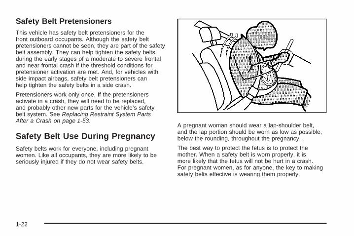
Safety Belt PretensionersThis vehicle has safety belt pretensioners for thefront outboard occupants. Although the safety beltpretensioners cannot be seen, they are part of the safetybelt assembly. They can help tighten the safety beltsduring the early stages of a moderate to severe frontaland near frontal crash if the threshold conditions forpretensioner activation are met. And, for vehicles withside impact airbags, safety belt pretensioners canhelp tighten the safety belts in a side crash.
Pretensioners work only once. If the pretensionersactivate in a crash, they will need to be replaced,and probably other new parts for the vehicle’s safetybelt system. See Replacing Restraint System PartsAfter a Crash on page 1-53.
Safety Belt Use During PregnancySafety belts work for everyone, including pregnantwomen. Like all occupants, they are more likely to beseriously injured if they do not wear safety belts.
A pregnant woman should wear a lap-shoulder belt,and the lap portion should be worn as low as possible,below the rounding, throughout the pregnancy.
The best way to protect the fetus is to protect themother. When a safety belt is worn properly, it ismore likely that the fetus will not be hurt in a crash.For pregnant women, as for anyone, the key to makingsafety belts effective is wearing them properly.
1-22

Safety Belt ExtenderIf the safety belt will fasten around you, you shoulduse it.
But if a safety belt is not long enough, your dealer/retailer will order you an extender. When you go in toorder it, take the heaviest coat you will wear, so theextender will be long enough for you. To help avoidpersonal injury, do not let someone else use it, and use itonly for the seat it is made to fit. The extender has beendesigned for adults. Never use it for securing child seats.To wear it, attach it to the regular safety belt. For moreinformation, see the instruction sheet that comes with theextender.
Child Restraints
Older Children
Older children who have outgrown booster seats shouldwear the vehicle’s safety belts.
1-23

The manufacturer’s instructions that come with thebooster seat, state the weight and height limitations forthat booster. Use a booster seat with a lap-shoulderbelt until the child passes the below fit test:
• Sit all the way back on the seat. Do the knees bendat the seat edge? If yes, continue. If no, return tothe booster seat.
• Buckle the lap-shoulder belt. Does the shoulder beltrest on the shoulder? If yes, continue. If no, thenreturn to the booster seat.
• Does the lap belt fit low and snug on the hips,touching the thighs? If yes, continue. If no, returnto the booster seat.
• Can proper safety belt fit be maintained for thelength of the trip? If yes, continue. If no, returnto the booster seat.
Q: What is the proper way to wear safety belts?
A: An older child should wear a lap-shoulder belt andget the additional restraint a shoulder belt canprovide. The shoulder belt should not cross the faceor neck. The lap belt should fit snugly below the hips,just touching the top of the thighs. This applies beltforce to the child’s pelvic bones in a crash. It shouldnever be worn over the abdomen, which could causesevere or even fatal internal injuries in a crash.
According to accident statistics, children and infants aresafer when properly restrained in rear seating positionsthan in the front seating positions.
In a crash, children who are not buckled up can strikeother people who are buckled up, or can be thrownout of the vehicle. Older children need to use safetybelts properly.
1-24

{CAUTION:
Never do this.
Never allow two children to wear the same safetybelt. The safety belt can not properly spread theimpact forces. In a crash, the two children can becrushed together and seriously injured. A safetybelt must be used by only one person at a time.
1-25

{CAUTION:
Never do this.
Never allow a child to wear the safety belt with theshoulder belt behind their back. A child can beseriously injured by not wearing the lap-shoulderbelt properly. In a crash, the child would not berestrained by the shoulder belt. The child couldmove too far forward increasing the chance ofhead and neck injury. The child might also slideunder the lap belt. The belt force would then beapplied right on the abdomen. That could causeserious or fatal injuries. The shoulder belt shouldgo over the shoulder and across the chest.
1-26

Infants and Young ChildrenEveryone in a vehicle needs protection! This includesinfants and all other children. Neither the distancetraveled nor the age and size of the traveler changesthe need, for everyone, to use safety restraints. In fact,the law in every state in the United States and inevery Canadian province says children up to someage must be restrained while in a vehicle.
{CAUTION:
Children can be seriously injured or strangled if ashoulder belt is wrapped around their neck andthe safety belt continues to tighten. Never leavechildren unattended in a vehicle and never allowchildren to play with the safety belts.
Airbags plus lap-shoulder belts offer protection for adultsand older children, but not for young children and infants.Neither the vehicle’s safety belt system nor its airbagsystem is designed for them. Every time infants andyoung children ride in vehicles, they should have theprotection provided by appropriate child restraints.
Children who are not restrained properly can strike otherpeople, or can be thrown out of the vehicle.
1-27

{CAUTION:
Never do this.
Never hold an infant or a child while riding in avehicle. Due to crash forces, an infant or a childwill become so heavy it is not possible to hold itduring a crash. For example, in a crash at only25 mph (40 km/h), a 12 lb (5.5 kg) infant willsuddenly become a 240 lb (110 kg) force on aperson’s arms. An infant should be secured inan appropriate restraint.
1-28

{CAUTION:
Never do this.
Children who are up against, or very close to,any airbag when it inflates can be seriously injuredor killed. Never put a rear-facing child restraint inthe right front seat. Secure a rear-facing childrestraint in a rear seat. It is also better to secure aforward-facing child restraint in a rear seat. If youmust secure a forward-facing child restraint in theright front seat, always move the front passengerseat as far back as it will go.
1-29

Q: What are the different types of add-on childrestraints?
A: Add-on child restraints, which are purchased by thevehicle’s owner, are available in four basic types.Selection of a particular restraint should take intoconsideration not only the child’s weight, height,and age but also whether or not the restraint willbe compatible with the motor vehicle in which itwill be used.
For most basic types of child restraints, there aremany different models available. When purchasinga child restraint, be sure it is designed to beused in a motor vehicle. If it is, the restraint willhave a label saying that it meets federal motorvehicle safety standards.
The restraint manufacturer’s instructions that comewith the restraint state the weight and heightlimitations for a particular child restraint. In addition,there are many kinds of restraints available forchildren with special needs.
{CAUTION:
To reduce the risk of neck and head injury duringa crash, infants need complete support. This isbecause an infant’s neck is not fully developedand its head weighs so much compared withthe rest of its body. In a crash, an infant in arear-facing child restraint settles into the restraint,so the crash forces can be distributed across thestrongest part of an infant’s body, the back andshoulders. Infants should always be secured inrear-facing child restraints.
1-30

{CAUTION:
A young child’s hip bones are still so small thatthe vehicle’s regular safety belt may not remainlow on the hip bones, as it should. Instead, it maysettle up around the child’s abdomen. In a crash,the belt would apply force on a body area that isunprotected by any bony structure. This alonecould cause serious or fatal injuries. To reducethe risk of serious or fatal injuries during a crash,young children should always be secured inappropriate child restraints.
Child Restraint Systems
A rear-facing infant seat (A)provides restraint with theseating surface against theback of the infant.
The harness system holds the infant in place and, in acrash, acts to keep the infant positioned in the restraint.
A forward-facing childseat (B) provides restraintfor the child’s bodywith the harness.
1-31

A booster seat (C-D) is a child restraint designed toimprove the fit of the vehicle’s safety belt system.A booster seat can also help a child to see out thewindow.
Securing an Add-on Child Restraint inthe Vehicle
{CAUTION:
A child can be seriously injured or killed in a crashif the child restraint is not properly secured in thevehicle. Secure the child restraint properly in thevehicle using the vehicle’s safety belt, followingthe instructions that came with that child restraintand the instructions in this manual.
To help reduce the chance of injury, the child restraintmust be secured in the vehicle. Child restraint systemsmust be secured in vehicle seats by lap belts or thelap belt portion of a lap-shoulder belt. A child canbe endangered in a crash if the child restraint is notproperly secured in the vehicle.
1-32

When securing an add-on child restraint, refer to theinstructions that come with the restraint which may beon the restraint itself or in a booklet, or both, and to thismanual. The child restraint instructions are important,so if they are not available, obtain a replacementcopy from the manufacturer.
Keep in mind that an unsecured child restraint canmove around in a collision or sudden stop and injurepeople in the vehicle. Be sure to properly secureany child restraint in your vehicle — even when nochild is in it.
Securing the Child Within the ChildRestraint
{CAUTION:
A child can be seriously injured or killed in a crashif the child is not properly secured in the childrestraint. Secure the child properly following theinstructions that came with that child restraint.
Lower Anchors and Tethers forChildren (LATCH)Some child restraints have a LATCH system. As part ofthe LATCH system, your child restraint may have lowerattachments and/or a top tether. The LATCH system canhelp hold the child restraint in place during driving or ina crash. Some vehicles have lower and/or top tetheranchors designed to secure a child restraint with lowerattachments and/or a top tether.Some child restraints with a top tether are designed tobe used whether the top tether is anchored or not.Other child restraints require that the top tetherbe anchored. A national or local law may requirethat the top tether be anchored.In Canada, the law requires that forward-facing childrestraints have a top tether, and that the tether beattached.Your vehicle does not have lower anchors or top tetheranchors to secure a child restraint with the LATCHsystem. If a national or local law requires that yourtop tether be anchored, do not use a child restraintin this vehicle because a top tether cannot be properlyanchored. You must use the safety belts to secure yourchild restraint in this vehicle, unless a national or locallaw requires that the top tether be anchored. Refer toyour child restraint instructions and instructions in thismanual for securing a child restraint using the vehicle’ssafety belts.
1-33

Securing a Child Restraint in theRight Front Seat PositionThis vehicle has airbags. In addition, the vehiclehas a passenger sensing system which is designedto turn off the right front passenger frontal airbag andseat-mounted side impact airbag under certainconditions. See Passenger Sensing System onpage 1-45 and Passenger Airbag Status Indicator onpage 3-45 for more information, including importantsafety information.
A label on the sun visor says, “Never put a rear-facingchild seat in the front.” This is because the risk tothe rear-facing child is so great, if the airbag deploys.
{CAUTION:
A child in a rear-facing child restraint can beseriously injured or killed if the right front passengerairbag inflates. This is because the back of therear-facing child restraint would be very close to the
CAUTION: (Continued)
CAUTION: (Continued)
inflating airbag. A child in a forward-facing childrestraint can be seriously injured or killed if theright front passenger airbag inflates and thepassenger seat is in a forward position.
Even if the passenger sensing system has turnedoff the right front passenger frontal airbag, nosystem is fail-safe. No one can guarantee thatan airbag will not deploy under some unusualcircumstance, even though it is turned off.
Secure rear-facing child restraints in a rearseat, even if the airbag is off. If you secure aforward-facing child restraint in the right front seat,always move the front passenger seat as far backas it will go. It is better to secure the child restraintin a rear seat.
See Passenger Sensing System on page 1-45 foradditional information.
1-34

Rear-facing child restraints should not be installed in thevehicle, even if the airbags are off.
If your child restraint has the LATCH system, see LowerAnchors and Tethers for Children (LATCH) on page 1-33for how and where to install the child restraint usingLATCH. If a child restraint is secured using a safety beltand it uses a top tether, see Lower Anchors and Tethersfor Children (LATCH) on page 1-33 for top tether anchorlocations.
Do not secure a child seat in a position without a toptether anchor if a national or local law requires thatthe top tether be anchored, or if the instructionsthat come with the child restraint say that the topstrap must be anchored.
In Canada, the law requires that forward-facing childrestraints have a top tether, and that the tether beattached.
You will be using the lap-shoulder belt to secure thechild restraint in this position. Follow the instructions thatcame with the child restraint.
1. Move the seat as far back as it will go beforesecuring the forward-facing child restraint.When the passenger sensing system has turnedoff the right front passenger frontal airbag andseat-mounted side impact airbag, the off indicatoron the passenger airbag status indicator shouldlight and stay lit when you start the vehicle. SeePassenger Airbag Status Indicator on page 3-45.
2. Put the child restraint on the seat.
3. Pick up the latch plate, and run the lap and shoulderportions of the vehicle’s safety belt through oraround the restraint. The child restraint instructionswill show you how.
1-35

4. Push the latch plate into the buckle until it clicks.Position the release button on the buckle so thatthe safety belt could be quickly unbuckled ifnecessary.
5. Pull the rest of the shoulder belt all the way out ofthe retractor to set the lock.
1-36

6. To tighten the belt, push down on the child restraint,pull the shoulder portion of the belt to tighten the lapportion of the belt and feed the shoulder belt backinto the retractor. When installing a forward-facingchild restraint, it may be helpful to use your kneeto push down on the child restraint as you tightenthe belt.
7. Push and pull the child restraint in differentdirections to be sure it is secure.
If the airbags are off, the off indicator in the passengerairbag status indicator will come on and stay onwhen the vehicle is started.
If a child restraint has been installed and the onindicator is lit, see “If the On Indicator is Lit for aChild Restraint” under Passenger Sensing Systemon page 1-45 for more information.
To remove the child restraint, unbuckle the vehiclesafety belt and let it return to the stowed position.
1-37

Airbag SystemThe vehicle has the following airbags:
• A frontal airbag for the driver.
• A frontal airbag for the right front passenger.
• A seat-mounted side impact airbag for the driver.
• A seat-mounted side impact airbag for the right frontpassenger.
All of the airbags in your vehicle will have the wordAIRBAG embossed in the trim or on an attached labelnear the deployment opening.
For frontal airbags, the word AIRBAG will appear onthe middle part of the steering wheel for the driver andon the instrument panel for the right front passenger.
With seat-mounted side impact airbags, the wordAIRBAG will appear on the side of the seatbackclosest to the door.
Airbags are designed to supplement the protectionprovided by safety belts. Even though today’s airbagsare also designed to help reduce the risk of injuryfrom the force of an inflating bag, all airbags must inflatevery quickly to do their job.
Here are the most important things to know about theairbag system:
{CAUTION:
You can be severely injured or killed in a crash ifyou are not wearing your safety belt — even if youhave airbags. Airbags are designed to work withsafety belts, but do not replace them. Also, airbagsare not designed to deploy in every crash. In somecrashes safety belts are your only restraint. SeeWhen Should an Airbag Inflate? on page 1-42.
Wearing your safety belt during a crash helpsreduce your chance of hitting things inside thevehicle or being ejected from it. Airbags are“supplemental restraints” to the safety belts.Everyone in your vehicle should wear a safetybelt properly — whether or not there is an airbagfor that person.
1-38

{CAUTION:
Airbags inflate with great force, faster than theblink of an eye. Anyone who is up against, or veryclose to, any airbag when it inflates can be seriouslyinjured or killed. Do not sit unnecessarily close tothe airbag, as you would be if you were sitting onthe edge of your seat or leaning forward. Safetybelts help keep you in position before and during acrash. Always wear your safety belt, even withairbags. The driver should sit as far back aspossible while still maintaining control of thevehicle.
Occupants should not lean on or sleep against thedoor or side windows in seating positions withseat-mounted airbags.
{CAUTION:
Children who are up against, or very close to,any airbag when it inflates can be seriously injuredor killed. Airbags plus lap-shoulder belts offerprotection for adults and older children, but not foryoung children and infants. Neither the vehicle’ssafety belt system nor its airbag system is designedfor them. Young children and infants need theprotection that a child restraint system can provide.Always secure children properly in your vehicle.To read how, see Older Children on page 1-23 orInfants and Young Children on page 1-27.
There is an airbagreadiness light on theinstrument panel cluster,which shows the airbagsymbol.
The system checks the airbag electrical system formalfunctions. The light tells you if there is an electricalproblem. See Airbag Readiness Light on page 3-44for more information.
1-39

Where Are the Airbags?
The driver frontal airbag is in the middle of the steeringwheel.
The passenger frontal airbag is in the instrument panelon the passenger side.
1-40

The seat-mounted side impact airbags for the driver andright front passenger are in the side of the seatbacksclosest to the door.
{CAUTION:
If something is between an occupant and anairbag, the airbag might not inflate properly or itmight force the object into that person causingsevere injury or even death. The path of aninflating airbag must be kept clear. Do not putanything between an occupant and an airbag,and do not attach or put anything on the steeringwheel hub or on or near any other airbagcovering.
Do not use seat accessories that block theinflation path of a seat-mounted side impactairbag.
Driver Side shown, Passenger Side similar
1-41

When Should an Airbag Inflate?Frontal airbags are designed to inflate in moderate tosevere frontal or near-frontal crashes to help reduce thepotential for severe injuries mainly to the driver’s or rightfront passenger’s head and chest. However, they are onlydesigned to inflate if the impact exceeds a predetermineddeployment threshold. Deployment thresholds are usedto predict how severe a crash is likely to be in time for theairbags to inflate and help restrain the occupants.Whether your frontal airbags will or should deploy is notbased on how fast your vehicle is traveling. It dependslargely on what you hit, the direction of the impact,and how quickly your vehicle slows down.Frontal airbags may inflate at different crash speeds.For example:• If the vehicle hits a stationary object, the airbags
could inflate at a different crash speed than if thevehicle hits a moving object.
• If the vehicle hits an object that deforms, theairbags could inflate at a different crash speed thanif the vehicle hits an object that does not deform.
• If the vehicle hits a narrow object (like a pole), theairbags could inflate at a different crash speedthan if the vehicle hits a wide object (like a wall).
• If the vehicle goes into an object at an angle, theairbags could inflate at a different crash speedthan if the vehicle goes straight into the object.
Thresholds can also vary with specific vehicle design.In addition, your vehicle has dual-stage frontal airbags.Dual-stage airbags adjust the restraint according tocrash severity. Your vehicle has electronic frontalsensors, which help the sensing system distinguishbetween a moderate frontal impact and a more severefrontal impact. For moderate frontal impacts, dual-stageairbags inflate at a level less than full deployment.For more severe frontal impacts, full deployment occurs.Frontal airbags are not intended to inflate duringvehicle rollovers, rear impacts, or in many side impacts.The vehicle has seat-mounted side impact airbags.See Airbag System on page 1-38. Seat-mounted sideimpact airbags are intended to inflate in moderateto severe side crashes. Seat-mounted side impactairbags will inflate if the crash severity is abovethe system’s designed threshold level. The thresholdlevel can vary with specific vehicle design.Seat-mounted side impact airbags are not intended toinflate in frontal impacts, near-frontal impacts, rollovers,or rear impacts. A seat-mounted side impact airbag isintended to deploy on the side of the vehicle that isstruck.The vehicle has seat position sensors which enables thesensing system to monitor the position of the driver seatand the right front passenger seat. Seat position sensorsprovide information that is used to determine if theairbags should deploy at a reduced level or at fulldeployment.
1-42

In any particular crash, no one can say whether anairbag should have inflated simply because of thedamage to a vehicle or because of what the repaircosts were. For seat-mounted side impact airbags,deployment is determined by the location and severityof the side impact.
What Makes an Airbag Inflate?In a deployment event, the sensing system sendsan electrical signal triggering a release of gas from theinflator. Gas from the inflator fills the airbag causing thebag to break out of the cover and deploy. The inflator, theairbag, and related hardware are all part of the airbagmodule.
Frontal airbag modules are located inside thesteering wheel and instrument panel. For vehicleswith seat-mounted side impact airbags, there areairbag modules in the side of the front seatbacksclosest to the door.
How Does an Airbag Restrain?In moderate to severe frontal or near frontal collisions,even belted occupants can contact the steering wheelor the instrument panel. In moderate to severe sidecollisions, even belted occupants can contact the insideof the vehicle.
Airbags supplement the protection provided by safetybelts. Frontal airbags distribute the force of theimpact more evenly over the occupant’s upper body,stopping the occupant more gradually. Seat-mountedside impact airbags distribute the force of the impactmore evenly over the occupant’s upper body.
But airbags would not help in many types of collisions,primarily because the occupant’s motion is not towardthose airbags. See When Should an Airbag Inflate? onpage 1-42 for more information.
Airbags should never be regarded as anything morethan a supplement to safety belts.
1-43

What Will You See After an AirbagInflates?After the frontal and seat-mounted side impactairbags inflate, they quickly deflate, so quickly thatsome people may not even realize the airbags inflated.Some components of the airbag module may be hot forseveral minutes. For location of the airbag modules, seeWhat Makes an Airbag Inflate? on page 1-43.
The parts of the airbag that come into contact with youmay be warm, but not too hot to touch. There may besome smoke and dust coming from the vents in thedeflated airbags. Airbag inflation does not prevent thedriver from seeing out of the windshield or being able tosteer the vehicle, nor does it prevent people from leavingthe vehicle.
{CAUTION:
When an airbag inflates, there may be dust in theair. This dust could cause breathing problems forpeople with a history of asthma or other breathingtrouble. To avoid this, everyone in the vehicleshould get out as soon as it is safe to do so.If you have breathing problems but cannot get outof the vehicle after an airbag inflates, then getfresh air by opening a window or a door. If youexperience breathing problems following an airbagdeployment, you should seek medical attention.
The vehicle has a feature that may automaticallyunlock the doors, turn the interior lamps on, and turn onthe hazard warning flashers when the airbags inflate.You can lock the doors, turn the interior lamps off, andturn the hazard warning flashers off by using the controlsfor those features.
1-44

In many crashes severe enough to inflate the airbag,windshields are broken by vehicle deformation. Additionalwindshield breakage may also occur from the right frontpassenger airbag.
• Airbags are designed to inflate only once. After anairbag inflates, you will need some new parts for theairbag system. If you do not get them, the airbagsystem will not be there to help protect you in anothercrash. A new system will include airbag modules andpossibly other parts. The service manual for yourvehicle covers the need to replace other parts.
• The vehicle has a crash sensing and diagnosticmodule which records information after a crash.See Vehicle Data Recording and Privacy onpage 8-16 and Event Data Recorders on page 8-17.
• Let only qualified technicians work on the airbagsystem. Improper service can mean that the airbagsystem will not work properly. See your dealer/retailer for service.
Passenger Sensing SystemThe vehicle has a passenger sensing system for theright front passenger position. The passenger airbagstatus indicator will be visible in the rearview mirrorwhen the vehicle is started.
The words ON and OFF, or the symbol for on and off,will be visible during the system check. When the systemcheck is complete, either the word ON or OFF, or thesymbol for on or off, will be visible. See Passenger AirbagStatus Indicator on page 3-45.
United States
Canada
1-45

The passenger sensing system will turn off the rightfront passenger frontal airbag and seat-mountedside impact airbag under certain conditions. The driverairbags are not affected by the passenger sensingsystem.
The passenger sensing system works with sensors thatare part of the right front passenger seat. The sensorsare designed to detect the presence of a properly-seatedoccupant and determine if the right front passengerfrontal airbag and seat-mounted side impact airbagshould be enabled (may inflate) or not.
According to accident statistics, children are safer whenproperly secured in a rear seat in the correct childrestraint for their weight and size. We recommend thatrear-facing child restraints not be transported in thevehicle, even if the airbags are off.
A label on the sun visor says, “Never put a rear-facingchild seat in the front.” This is because the risk tothe rear-facing child is so great, if the airbag deploys.
{CAUTION:
A child in a rear-facing child restraint can beseriously injured or killed if the right frontpassenger airbag inflates. This is because theback of the rear-facing child restraint would bevery close to the inflating airbag. A child in aforward-facing child restraint can be seriouslyinjured or killed if the right front passenger airbaginflates and the passenger seat is in a forwardposition.
Even if the passenger sensing system has turnedoff the right front passenger frontal airbag andseat-mounted side impact airbag (if equipped),no system is fail-safe. No one can guarantee thatan airbag will not deploy under some unusualcircumstance, even though the airbag(s) are off.
Secure rear-facing child restraints in a rear seat,even if the airbag(s) are off. If you secure aforward-facing child restraint in the right front seat,always move the front passenger seat as far backas it will go. It is better to secure the child restraintin a rear seat.
1-46

The passenger sensing system is designed to turn offthe right front passenger frontal airbag and seat-mountedside impact airbag if:
• The right front passenger seat is unoccupied.
• The system determines that an infant is present in arear-facing infant seat.
• The system determines that a small child is presentin a child restraint.
• The system determines that a small child is presentin a booster seat.
• A right front passenger takes his/her weight off of theseat for a period of time.
• The right front passenger seat is occupied by asmaller person, such as a child who has outgrownchild restraints.
• Or, if there is a critical problem with the airbagsystem or the passenger sensing system.
When the passenger sensing system has turned off theright front passenger frontal airbag, and seat-mountedside impact airbag, the off indicator will light and stay litto remind you that the airbag(s) are off. See PassengerAirbag Status Indicator on page 3-45.
The passenger sensing system is designed to turn on(may inflate) the right front passenger frontal airbag andseat-mounted side impact airbag anytime the systemsenses that a person of adult size is sitting properly inthe right front passenger seat.When the passenger sensing system has allowed theairbags to be enabled, the on indicator will light and staylit to remind you that the airbags are active.For some children who have outgrown child restraintsand for very small adults, the passenger sensing systemmay or may not turn off the right front passenger frontalairbag and seat-mounted side impact airbag, dependingupon the person’s seating posture and body build.Everyone in the vehicle who has outgrown child restraintsshould wear a safety belt properly — whether or not thereis an airbag for that person.
{CAUTION:
If the airbag readiness light ever comes on andstays on, it means that something may be wrongwith the airbag system. To help avoid injury toyourself or others, have the vehicle serviced rightaway. See Airbag Readiness Light on page 3-44for more information, including important safetyinformation.
1-47

If the On Indicator is Lit for a ChildRestraintIf a child restraint has been installed and the onindicator is lit:1. Turn the vehicle off.2. Remove the child restraint from the vehicle.3. Remove any additional items from the seat such as
blankets, cushions, seat covers, seat heaters, orseat massagers.
4. Reinstall the child restraint following the directionsprovided by the child restraint manufacturer andrefer to Securing a Child Restraint in the Right FrontSeat Position on page 1-34.
5. If, after reinstalling the child restraint and restartingthe vehicle, the on indicator is still lit, turn the vehicleoff. Then slightly recline the vehicle seatback andadjust the seat cushion, if adjustable, to make surethat the vehicle seatback is not pushing the childrestraint into the seat cushion.
6. Restart the vehicle.The passenger sensing system may or may notturn off the airbag(s) for a child in a child restraintdepending upon the child’s seating posture andbody build.If the on indicator is still lit, do not install a childrestraint in this vehicle and check with yourdealer/retailer.
If the Off Indicator is Lit for anAdult-Size Occupant
If a person of adult-size is sitting in the right frontpassenger seat, but the off indicator is lit, it could bebecause that person is not sitting properly in the seat.
1-48

If this happens, use the following steps to allow thesystem to detect that person and enable the right frontpassenger frontal airbag and seat-mounted sideimpact airbag:
1. Turn the vehicle off.
2. Remove any additional material from the seat, suchas blankets, cushions, seat covers, seat heaters, orseat massagers.
3. Place the seatback in the fully upright position.
4. Have the person sit upright in the seat, centered onthe seat cushion, with legs comfortably extended.
5. Restart the vehicle and have the person remain inthis position for two to three minutes after the onindicator is lit.
Additional Factors Affecting SystemOperationSafety belts help keep the passenger in position on theseat during vehicle maneuvers and braking, which helpsthe passenger sensing system maintain the passengerairbag status. See “Safety Belts” and “Child Restraints” inthe Index for additional information about the importanceof proper restraint use.
If the shoulder portion of the belt is pulled out all theway, the child restraint locking feature will be engaged.This may unintentionally cause the passenger sensingsystem to turn the airbag(s) off for some adult sizeoccupants. If this happens, let the belt go back all theway and start again.
A thick layer of additional material, such as a blanket orcushion, or aftermarket equipment such as seat covers,seat heaters, and seat massagers can affect how well thepassenger sensing system operates. We recommendthat you not use seat covers or other aftermarketequipment except when approved by GM for your specificvehicle. See Adding Equipment to Your Airbag-EquippedVehicle on page 1-50 for more information aboutmodifications that can affect how the system operates.
{CAUTION:
Stowing of articles under the passenger seat orbetween the passenger seat cushion and seatbackmay interfere with the proper operation of thepassenger sensing system.
1-49
Servicing Your Airbag-EquippedVehicleAirbags affect how the vehicle should be serviced.There are parts of the airbag system in several placesaround the vehicle. Your dealer/retailer and theservice manual have information about servicing thevehicle and the airbag system. To purchase a servicemanual, see Service Publications Ordering Informationon page 8-15.
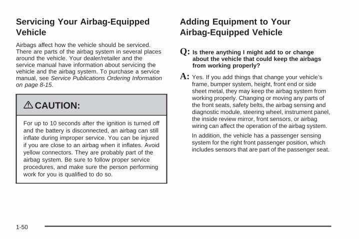
{CAUTION:
For up to 10 seconds after the ignition is turned offand the battery is disconnected, an airbag can stillinflate during improper service. You can be injuredif you are close to an airbag when it inflates. Avoidyellow connectors. They are probably part of theairbag system. Be sure to follow proper serviceprocedures, and make sure the person performingwork for you is qualified to do so.
Adding Equipment to YourAirbag-Equipped Vehicle
Q: Is there anything I might add to or changeabout the vehicle that could keep the airbagsfrom working properly?
A: Yes. If you add things that change your vehicle’sframe, bumper system, height, front end or sidesheet metal, they may keep the airbag system fromworking properly. Changing or moving any parts ofthe front seats, safety belts, the airbag sensing anddiagnostic module, steering wheel, instrument panel,the inside review mirror, front sensors, or airbagwiring can affect the operation of the airbag system.
In addition, the vehicle has a passenger sensingsystem for the right front passenger position, whichincludes sensors that are part of the passenger seat.
1-50

The passenger sensing system may not operateproperly if the original seat trim is replacedwith non-GM covers, upholstery or trim, orwith GM covers, upholstery or trim designedfor a different vehicle. Any object, such as anaftermarket seat heater or a comfort enhancingpad or device, installed under or on top of theseat fabric, could also interfere with theoperation of the passenger sensing system.This could either prevent proper deployment ofthe passenger airbag(s) or prevent the passengersensing system from properly turning off thepassenger airbag(s). See Passenger SensingSystem on page 1-45.
If you have any questions about this, you shouldcontact Customer Assistance before you modifyyour vehicle. The phone numbers and addressesfor Customer Assistance are in Step Two ofthe Customer Satisfaction Procedure in this manual.See Customer Satisfaction Procedure on page 8-2.
Q: Because I have a disability, I have to get myvehicle modified. How can I find out whetherthis will affect my airbag system?
A: If you have questions, call Customer Assistance.The phone numbers and addresses for CustomerAssistance are in Step Two of the CustomerSatisfaction Procedure in this manual. SeeCustomer Satisfaction Procedure on page 8-2.
Your dealer/retailer and the service manual haveinformation about the location of the airbag sensors,sensing and diagnostic module and airbag wiring.
1-51

Restraint System Check
Checking the Restraint Systems
Safety BeltsNow and then, check the safety belt reminder light,safety belts, buckles, latch plates, retractors, andanchorages are all working properly.
Look for any other loose or damaged safety belt systemparts that might keep a safety belt system from doing itsjob. See your dealer/retailer to have it repaired. Tornor frayed safety belts may not protect you in a crash.They can rip apart under impact forces. If a belt is tornor frayed, get a new one right away.
Make sure the safety belt reminder light is working.See Safety Belt Reminders on page 3-44 for moreinformation.
Keep safety belts clean and dry. See Care of SafetyBelts on page 6-76.
AirbagsThe airbag system does not need regularly scheduledmaintenance or replacement. Make sure the airbagreadiness light is working. See Airbag Readiness Lighton page 3-44 for more information.
Notice: If an airbag covering is damaged, opened,or broken, the airbag may not work properly.Do not open or break the airbag coverings. If thereare any opened or broken airbag covers, havethe airbag covering and/or airbag module replaced.For the location of the airbag modules, seeWhat Makes an Airbag Inflate? on page 1-43.See your dealer/retailer for service.
1-52

Replacing Restraint System PartsAfter a Crash
{CAUTION:
A crash can damage the restraint systems in yourvehicle. A damaged restraint system may notproperly protect the person using it, resulting inserious injury or even death in a crash. To helpmake sure your restraint systems are workingproperly after a crash, have them inspected andany necessary replacements made as soon aspossible.
If you have had a crash, do you need new belts?
After a very minor crash, nothing may be necessary.But the belt assemblies that were used during anycrash may have been stressed or damaged. See yourdealer/retailer to have your safety belt assembliesinspected or replaced.
New parts and repairs may be necessary even if thebelt was not being used at the time of the crash.
If an airbag inflates, you will need to replace airbagsystem parts. See the part on the airbag system earlierin this section.
Have your safety belt pretensioners checked if yourvehicle has been in a crash, or if your airbag readinesslight stays on after you start your vehicle or whileyou are driving. See Airbag Readiness Light onpage 3-44.
1-53

✍ NOTES
1-54

Keys ...............................................................2-3Keyless Access System ...................................2-4Keyless Access System Operation ....................2-5
Doors and Locks ............................................2-10Door Locks ..................................................2-10Power Door Locks ........................................2-13Automatic Door Lock .....................................2-13Programmable Automatic Door Unlock .............2-13Lockout Protection ........................................2-13Trunk ..........................................................2-14
Windows ........................................................2-17Power Windows ............................................2-18Sun Visors ...................................................2-20
Theft-Deterrent Systems ..................................2-20Theft-Deterrent System ..................................2-20Valet Lockout Switch .....................................2-22Immobilizer ..................................................2-22Immobilizer Operation ....................................2-23
Starting and Operating Your Vehicle ................2-24New Vehicle Break-In ....................................2-24Ignition Positions ..........................................2-24Retained Accessory Power (RAP) ...................2-25Starting the Engine .......................................2-26Automatic Transmission Operation ...................2-28Parking Brake ..............................................2-32Shifting Into Park ..........................................2-33Shifting Out of Park ......................................2-35Parking Over Things That Burn .......................2-35Engine Exhaust ............................................2-36Running the Vehicle While Parked ..................2-37
Mirrors ...........................................................2-38Automatic Dimming Rearview Mirror ................2-38Outside Power Mirrors ...................................2-38Outside Automatic Dimming Mirror ..................2-39Park Assist Mirror .........................................2-39Outside Convex Mirror ...................................2-39Outside Heated Mirrors ..................................2-39
Section 2 Features and Controls
2-1

Object Detection Systems ...............................2-40Ultrasonic Rear Parking Assist (URPA) ............2-40
OnStar® System .............................................2-42Universal Home Remote System ......................2-45
Universal Home Remote System Operation ......2-46Storage Areas ................................................2-53
Glove Box ...................................................2-53Cupholders ..................................................2-53
Center Console Storage .................................2-53Floor Mats ...................................................2-53Rear Storage Area ........................................2-54Convenience Net ..........................................2-54
Retractable Hardtop ........................................2-54Lowering the Retractable Hardtop ...................2-55Raising the Retractable Hardtop ......................2-56
Section 2 Features and Controls
2-2

Keys
{CAUTION:
Leaving children in a vehicle with the keylessaccess transmitter is dangerous for many reasons,children or others could be badly injured or evenkilled. They could operate the power windows orother controls or even make the vehicle move.The windows will function with the keyless accesstransmitter in the vehicle and they could beseriously injured or killed if caught in the path of aclosing window. Do not leave the keyless accesstransmitter in a vehicle with children.
2-3
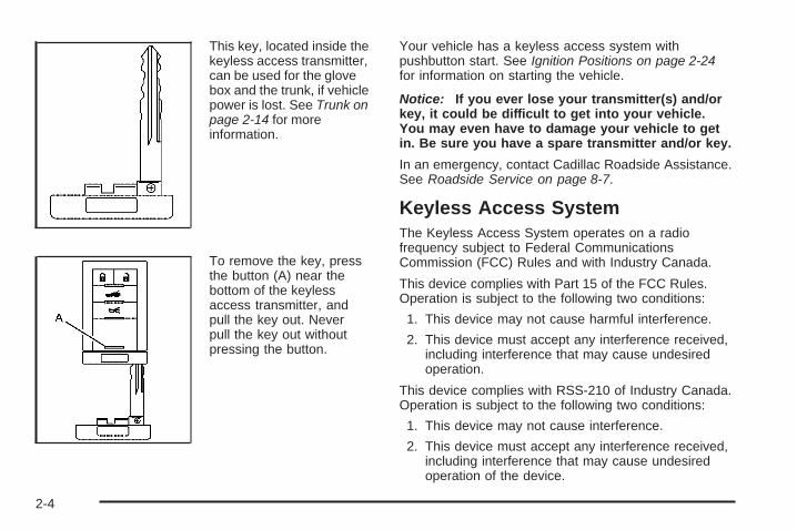
This key, located inside thekeyless access transmitter,can be used for the glovebox and the trunk, if vehiclepower is lost. See Trunk onpage 2-14 for moreinformation.
To remove the key, pressthe button (A) near thebottom of the keylessaccess transmitter, andpull the key out. Neverpull the key out withoutpressing the button.
Your vehicle has a keyless access system withpushbutton start. See Ignition Positions on page 2-24for information on starting the vehicle.
Notice: If you ever lose your transmitter(s) and/orkey, it could be difficult to get into your vehicle.You may even have to damage your vehicle to getin. Be sure you have a spare transmitter and/or key.
In an emergency, contact Cadillac Roadside Assistance.See Roadside Service on page 8-7.
Keyless Access SystemThe Keyless Access System operates on a radiofrequency subject to Federal CommunicationsCommission (FCC) Rules and with Industry Canada.
This device complies with Part 15 of the FCC Rules.Operation is subject to the following two conditions:
1. This device may not cause harmful interference.
2. This device must accept any interference received,including interference that may cause undesiredoperation.
This device complies with RSS-210 of Industry Canada.Operation is subject to the following two conditions:
1. This device may not cause interference.
2. This device must accept any interference received,including interference that may cause undesiredoperation of the device.
2-4

Changes or modifications to this system by other thanan authorized service facility could void authorization touse this equipment.
If there is a decrease in the keyless access transmitterrange, try this:
• Check the distance. The transmitter may be too farfrom the vehicle. It may be necessary to standcloser during rainy or snowy weather.
• Check the location. Other vehicles or objects maybe blocking the signal. Take a few steps to theleft or right, hold the transmitter higher, andtry again.
• Check the transmitter’s battery. See “BatteryReplacement” under Keyless Access SystemOperation on page 2-5.
• Make sure that an electronic device such as acellular phone or lap top computer is not causinginterference.
• If the transmitter is still not working correctly, seeyour dealer/retailer or a qualified technician forservice.
Keyless Access System OperationThe Keyless Access System transmitter functionswork up to 100 feet (30 m) away from the vehicle.
Keyless UnlockingPress the door handle sensor to unlock and open thedoors if the keyless access transmitter is within range.See Door Locks on page 2-10 and “Passive Unlocking”under DIC Vehicle Personalization on page 3-72 foradditional information.
Keyless LockingThe doors lock after several seconds if all doors areclosed and at least one keyless access transmitterhas been removed from the interior of the vehicle.To customize whether the doors automatically lock whenexiting the vehicle, see ″Passive Locking″ under DICVehicle Personalization on page 3-72 for additionalinformation.
2-5

Keyless Trunk OpeningPress the trunk release sensor, located on the rear ofthe trunk lid under the emblem, to open the trunk if thekeyless access transmitter is within range. See Trunkon page 2-14 for additional information.
There are other conditions which can affect theperformance of the transmitter. See Keyless AccessSystem on page 2-4.
This vehicle comes withtwo transmitters.Q (Lock): Press to lockthe doors. The indicatorlight on the door flashesonce. If Q is pressed twice,the doors lock, the lightflashes once and the hornsounds once.
K (Unlock): Press once to unlock the driver door.The indicator light on the door flashes twice.Press K twice within five seconds to unlock bothdoors. The interior lamps may come on.
Pressing K also recalls the memory settings. SeeMemory Seat, Mirrors and Steering Wheel on page 1-3for more information.
G (Trunk): Press and hold for about one second toopen the trunk. If the engine is running, the shift levermust be in P (Park).
L (Panic): Press to sound the vehicle alarm. Pressany other button on the keyless access transmitterto stop the vehicle alarm.
The vehicle comes with two transmitters. Eachtransmitter will have a number on top of it, ″1″ or ″2″.These numbers correspond to the driver of the vehicle.For example, the memory seat position for driver 1will be recalled when using the transmitter labeled ″1″,if enabled through the vehicle personalization. SeeMemory Seat, Mirrors and Steering Wheel on page 1-3and DIC Vehicle Personalization on page 3-72.
Programming Transmitters to theVehicleOnly keyless access transmitters programmed to thisvehicle will work. If a transmitter is lost or stolen, areplacement can be purchased and programmed throughyour dealer/retailer. The vehicle can be reprogrammed sothat lost or stolen transmitters no longer work. Eachvehicle can have up to four transmitters programmed to it.
2-6

Programming with a RecognizedTransmitterA new transmitter can be programmed to the vehiclewhen there is one recognized transmitter. For vehiclessold in Canada, two recognized transmitters arerequired to program a new transmitter.
1. The vehicle must be off.
2. Both the recognized and new transmitters must bewith you.
3. Insert the vehicle key into the key cylinder locatedon the lower rear fascia on the driver side of thevehicle. See Trunk on page 2-14 for moreinformation on the key cylinder.
4. Open the trunk.
5. Turn the key five times within five seconds.
6. The Driver Information Center (DIC) displaysREADY FOR FOB # 2, 3 or 4.
7. Place the new transmitter in the glove boxtransmitter pocket with the buttons facing thepassenger side.
2-7

8. A beep sounds once programming in complete.The DIC will display READY FOR #3 or 4, orMAX # FOBS LEARNED.
9. To program additional transmitters, repeat Step 7.Press Acc. on the ignition switch if programming iscomplete.
10. Press K on each newly programmed transmitter tocomplete the process.
Programming without a RecognizedTransmitterThis procedure requires three ten minutes cycles tocomplete the programming process. United Statesowners are permitted to program a new transmitter totheir vehicle when a recognized transmitter is notavailable. The Canadian immobilizer standard requiresthat Canadian owners see their dealer/retailer forprogramming new transmitters when two recognizedtransmitters are not available.
1. The vehicle must be off.
2. Place the new transmitter in the glove box transmitterpocket with the buttons facing the passenger side.
3. Insert the vehicle key into the key cylinder locatedon the lower rear fascia on the driver side of thevehicle. See Trunk on page 2-14 for moreinformation on the key cylinder.
4. Open the trunk.
5. Turn the key five times within five seconds.
6. The DIC message displays OFF-ACC TO LEARN.
2-8

7. Press Acc. on the ignition switch.
8. The DIC reads WAIT 10 MINUTES and countsdown to zero.
9. The DIC displays OFF-ACC TO LEARN again.
10. Press Acc. on the ignition switch.
11. Steps 8, 9 and 10 will be repeated two more times.
12. A beep sounds and the DIC reads READY FORFOB #1. All previously known transmitterprogramming has been erased.
13. A beep sounds once programming in complete.The DIC displays READY FOR FOB #2.To program additional transmitters, taketransmitter 1 out of the transmitter pocketand place transmitter 2 in the pocket.Up to four transmitters can be programmed.The DIC then displays MAXIMUM NUMBEROF FOBS LEARNED and exits theprogramming mode.Press Acc. on the ignition switch to complete theprocess.
14. Press Acc. on the ignition switch if programming iscomplete.
15. Press K on each newly programmed transmitter tocomplete the process.
Starting the Vehicle with a LowTransmitter BatteryIf the transmitter battery is weak, the DIC may displayNO FOB DETECTED when trying to start the vehicle.To start the vehicle, place the transmitter in the glove boxtransmitter pocket with the buttons facing the passengerside. Then, with the vehicle in P (Park) or N (Neutral),press the brake pedal and / . Replace the transmitterbattery as soon as possible. Change the transmitterbattery if the DIC displays FOB BATTERY LOW.
2-9

Battery ReplacementNotice: When replacing the battery, do not touchany of the circuitry on the transmitter. Staticfrom your body could damage the transmitter.
1. Separate the transmitter with a flat, thin objectinserted into the slot on the side of the transmitter.
2. Remove the old battery. Do not use a metal object.
3. Insert the new battery, positive side facing down.Replace with a CR2032 or equivalent battery.
4. Snap the transmitter back together.
Doors and Locks
Door Locks
{CAUTION:
Unlocked doors can be dangerous.• Passengers — especially children — can easily
open the doors and fall out of a moving vehicle.When a door is locked it will not open. Youincrease the chance of being thrown out of thevehicle in a crash if the doors are not locked.So, wear safety belts properly and lock thedoors whenever you drive.
• Young children who get into unlocked vehiclesmay be unable to get out. A child can beovercome by extreme heat and can sufferpermanent injuries or even death from heatstroke. Always lock your vehicle whenever youleave it.
• Outsiders can easily enter through an unlockeddoor when you slow down or stop your vehicle.Locking your doors can help prevent this fromhappening.
2-10

To lock or unlock your vehicle from the outside, use thekeyless access transmitter and press the appropriatelock or unlock button. You may also unlock and open thedoor passively when you squeeze the door handlesensor, as long as you have your transmitter with you.Passive entry occurs when the door handle sensoris pressed and the vehicle recognizes your keylessaccess transmitter. When the passenger door is openedfirst, the driver door will also become unlocked.
From the inside, use the power door lock buttonslocated at the top of the door panel near the window.See Power Door Locks on page 2-13 for moreinformation.
To open a door from the inside, press the button in frontof the door handle and push the door open.
If power to the vehicle or the keyless access transmitteris lost, there are two ways to open the door.
2-11
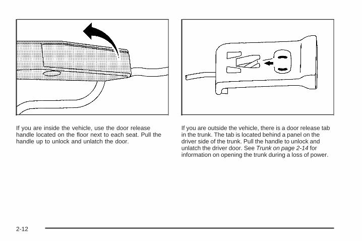
If you are inside the vehicle, use the door releasehandle located on the floor next to each seat. Pull thehandle up to unlock and unlatch the door.
If you are outside the vehicle, there is a door release tabin the trunk. The tab is located behind a panel on thedriver side of the trunk. Pull the handle to unlock andunlatch the driver door. See Trunk on page 2-14 forinformation on opening the trunk during a loss of power.
2-12

Power Door LocksThe power door lock switches are located on the doors.
There is an indicator light on the rear of the doornear the window.
K (Unlock): Press to unlock the doors.
When pressed, a beep sounds. If the door is closedwhen pressed, the light flashes twice. If the door is openwhen pressed, the light flashes.
Q (Lock): Press to lock the doors.
When pressed, a beep sounds. If the door is closedwhen pressed, the light comes on for a few seconds,then turns off. If the door is open when pressed, the lightstays on.
Automatic Door LockYour vehicle is programmed so that, when the doors areclosed, the ignition is on and the shift lever is moved outof P (Park), all the doors will lock.
If someone needs to get out while the vehicle is not inP (Park), have the person use the power door unlockswitch. When the door is closed again, the doors will lockeither when your foot is removed from the brake or thevehicle speed becomes faster than 8 mph (13 km/h).
Programmable Automatic DoorUnlockYour vehicle is programmed so that, when the shiftlever is moved into P (Park), both doors will unlock.
With the vehicle in P (Park) and the engine running,door unlocking can be programmed through promptsdisplayed on the Driver Information Center (DIC).These prompts allow the driver to choose variousunlock settings. For programming information,see DIC Vehicle Personalization on page 3-72.
Lockout ProtectionYour vehicle can be programmed to sound the hornthree times and unlock the driver door when both doorsare closed and there is a keyless access transmitterinside the vehicle. When the driver door is opened,a reminder chime will sound continuously. The vehiclewill remain locked only when at least one transmitter hasbeen removed from the vehicle and both doors areclosed. See DIC Vehicle Personalization on page 3-72.
2-13

Trunk
{CAUTION:
Exhaust gases may enter the vehicle if it is drivenwith the liftgate, trunk/hatch open, or with anyobjects that pass through the seal between thebody and the trunk/hatch or liftgate. Engineexhaust contains Carbon Monoxide (CO) whichcannot be seen or smelled. It can causeunconsciousness and even death.
If the vehicle must be driven with the liftgate, ortrunk/hatch open:
• Close all of the windows• Fully open the air outlets on or under the
instrument panel• Adjust the Climate Control system to a setting
that brings in only outside air and set the fanspeed to the highest setting. See ClimateControl System in the Index.
• If the vehicle is equipped with a power liftgate,disable the power liftgate function.
For more information about carbon monoxide, seeEngine Exhaust Engine Exhaust on page 2-36.
Trunk Lock Release
{CAUTION:
Moving parts of the powered trunk lid can bedangerous. You or others could be injured. Keepyourself and others away from the trunk lid and itsmechanism while it is closing.
This button is located tothe left of the steeringwheel on the instrumentpanel.
Press to open the trunk. To use, the vehicle must be inP (Park) or N (Neutral) and the valet lockout switchmust be off.
2-14

You can also press G on the keyless accesstransmitter to open the trunk. To disable this feature,see “Valet Lockout Switch” under Theft-DeterrentSystems on page 2-20.
You may passively enter the trunk when you squeeze thetrunk release sensor located on the rear of the trunk lidunder the emblem, as long as you have your transmitterwith you. The vehicle must be in PARK (P) and the valetlockout switch must be off. See Valet Lockout Switch onpage 2-22.
To close the trunk, press G on the underside of thetrunk lid.
To stop the trunk lid while it is closing, do one of thefollowing:
• Press the trunk lock release button located on theinstrument panel.
• Use the vehicle key.
• Squeeze the trunk release sensor located on therear of the trunk lid.
• Press G on the keyless access transmitter.
• Press the trunk close button on the underside of thetrunk lid.
To begin opening the trunk from the stopped position,use any of the methods above, except pressing the trunkclose button.
To resume closing the power trunk lid, press the trunkclose button on the underside of the trunk lid.
If the vehicle has lost battery power, you can still openthe trunk using the vehicle key. See Keys on page 2-3for more information.
2-15

The key cylinder is located behind a cover on the lowerrear fascia on the driver side of the vehicle. Open thedoor to access the key cylinder.
Emergency Trunk Release Handle
Notice: Do not use the emergency trunk releasehandle as a tie-down or anchor point when securingitems in the trunk as it could damage the handle.
There is a glow-in-the-dark emergency trunk releasehandle located inside the trunk near the latch.This handle will glow following exposure to light.Pull the release handle and push up on the trunklid to release the latch from the inside.
2-16

Windows
{CAUTION:
Leaving children, helpless adults, or pets in avehicle with the windows closed is dangerous.They can be overcome by the extreme heat andsuffer permanent injuries or even death from heatstroke. Never leave a child, a helpless adult, or apet alone in a vehicle, especially with the windowsclosed in warm or hot weather.
2-17
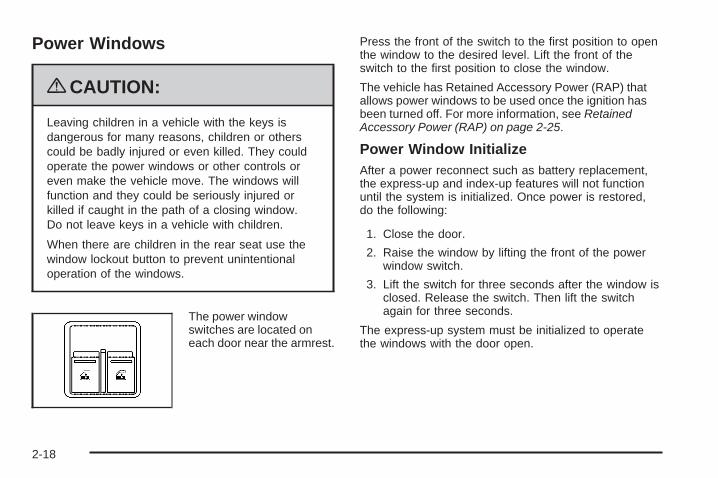
Power Windows
{CAUTION:
Leaving children in a vehicle with the keys isdangerous for many reasons, children or otherscould be badly injured or even killed. They couldoperate the power windows or other controls oreven make the vehicle move. The windows willfunction and they could be seriously injured orkilled if caught in the path of a closing window.Do not leave keys in a vehicle with children.
When there are children in the rear seat use thewindow lockout button to prevent unintentionaloperation of the windows.
The power windowswitches are located oneach door near the armrest.
Press the front of the switch to the first position to openthe window to the desired level. Lift the front of theswitch to the first position to close the window.
The vehicle has Retained Accessory Power (RAP) thatallows power windows to be used once the ignition hasbeen turned off. For more information, see RetainedAccessory Power (RAP) on page 2-25.
Power Window InitializeAfter a power reconnect such as battery replacement,the express-up and index-up features will not functionuntil the system is initialized. Once power is restored,do the following:
1. Close the door.
2. Raise the window by lifting the front of the powerwindow switch.
3. Lift the switch for three seconds after the window isclosed. Release the switch. Then lift the switchagain for three seconds.
The express-up system must be initialized to operatethe windows with the door open.
2-18
Express Window
Down: Press the front of the window switch tothe second position and release to activate theexpress-down feature. To stop the window, briefly liftthe switch.
Up: Lift the front of the switch briefly to activate theexpress-up feature. To stop the window, briefly pressthe switch.
Express-Up WindowThis feature is on both power windows. Press the uparrow on the switch to the second position to activate theexpress-up feature. If you want to stop the window asit is raising, press the switch again.
Express Window Anti-Pinch FeatureIf any object is in the path of the window when theexpress-up is active, the window will stop at theobstruction and auto-reverse to a preset factory position.Weather conditions such as severe icing may also causethe window to auto-reverse. The window will return tonormal operation once the obstruction or condition isremoved.
{CAUTION:
If express override is activated, the window will notreverse automatically. You or others could beinjured and the window could be damaged. Beforeyou use express override, make sure that all peopleand obstructions are clear of the window path.
Express Window Anti-Pinch OverrideIn an emergency, the anti-pinch feature can beoverridden in a supervised mode. Hold the window switchall the way down in the express position. The window willrise for as long as the switch is held. Once the switch isreleased, the express mode is re-activated.
In this mode, the window can still close on an object inits path. Use care when using the override mode.
2-19

Window IndexingThis feature automatically lowers the window a smallamount when the door is opened. Then, when the dooris closed, the window will raise to its full up position.
Sun VisorsNotice: Raising or lowering the retractable hardtopwith the visor or the visor vanity mirror cover upmay cause damage to the visor or mirror cover.Always return the visor to the center mount or lowerthe cover on the visor vanity mirror before raisingor lowering the retractable hardtop.
Swing down the visor to block out glare. It can also bedetached from the center mount and moved to the side.
Lighted Visor Vanity MirrorsSwing the visor down and lift the cover. The lamp willautomatically come on when the cover is opened.
Theft-Deterrent SystemsVehicle theft is big business, especially in some cities.This vehicle has theft-deterrent features, however,they do not make it impossible to steal.
Theft-Deterrent System
With this system, thesecurity light will flashwhen the door is open andlocked with the powerdoor lock switch.
If this light is on continuously while the engine isrunning, your vehicle needs service.
2-20

Arming the SystemTo arm the system:
• Press Q on the keyless access transmitter.
• Open the door. Lock the door with the power doorlock switch. The security light should flash. Removethe keyless access transmitter from the interior of thevehicle and close the door. The security light will stopflashing and stay on. After 30 seconds, the lightshould turn off.
The vehicle can be programmed to automatically lockthe doors and arm the system when you exit thevehicle. See DIC Vehicle Personalization onpage 3-72.
Now, if a door or the trunk lid is opened without thekeyless access transmitter, the alarm will go off.The horn will sound for two minutes, then it will gooff to save battery power. And, the vehicle will notstart without a keyless transmitter present.
The theft-deterrent system will not arm if you lock thedriver door with the power door lock switch afterthe doors are closed.
If the passenger stays in the vehicle when you leave withthe keyless access transmitter, have the passenger lockthe vehicle after the doors are closed. This way the alarmwill not arm, and the passenger will not set it off.
Testing the AlarmTo test the system:
1. Close the trunk lid.
2. Lower the window on the driver door.
3. Manually arm the system.
4. Close the doors and wait 30 seconds.
5. Reach through the open window and manually pullthe release lever on the floor.
6. Turn off the alarm by pressing K on the transmitter.
If the alarm is inoperative, check to see if the hornworks. If not, check the horn fuse. See Fuses and CircuitBreakers on page 6-83. If the horn works, but thealarm doesn’t go off, see your dealer/retailer.
Disarming the SystemAlways use the keyless access transmitter to unlock adoor either by pressing K on the transmitter or bysqueezing the door handle sensor while you have thetransmitter with you. Unlocking a door any other way willset off the alarm. If the alarm sounds, press K on thekeyless access transmitter to disarm it.
Do not leave the key or device that disarms ordeactivates the theft deterrent system in the vehicle.
2-21

Valet Lockout Switch
This switch is locatedinside the glove box.
Press ON to disable the use of the trunk and convertibletop. The trunk cannot be opened except by using the keyif the valet lockout is on.
Press OFF to enable the use of the trunk andconvertible top.
Locking the glove box with the key will also help tosecure the vehicle.
ImmobilizerThis device complies with Part 15 of the FCC Rules.Operation is subject to the following two conditions:
1. This device may not cause interference.
2. This device must accept any interference received,including interference that may cause undesiredoperation.
This device complies with RSS-210 of Industry Canada.Operation is subject to the following two conditions:
1. This device may not cause interference.
2. This device must accept any interference received,including interference that may cause undesiredoperation of the device.
Changes or modifications to this system by other thanan authorized service facility could void authorization touse this equipment.
2-22

Immobilizer OperationThe vehicle has a passive theft-deterrent system.
The system is automatically armed when the ignition isturned off.
The immobilization system is disarmed when the ignitionis turned to OFF/ACCESSORY or START and a validtransmitter is found in the vehicle.
You do not have to manually arm or disarm the system.
The security light comes on if there is a problem witharming or disarming the theft-deterrent system.
The system has one or more keyless access transmittersthat are matched to an immobilizer control unit in thevehicle. Only a correctly matched keyless accesstransmitter starts the vehicle. The vehicle may notstart if the keyless access transmitter is damaged.
If the engine does not start and the security light comeson, there may be a problem with the immobilizer system.Press the START button again.
If the vehicle does not start and the keyless accesstransmitter appears to be undamaged, try anotherkeyless access transmitter. Or, place the transmitter inthe transmitter pocket. See “NO FOBS DETECTED”under DIC Warnings and Messages on page 3-60 foradditional information. Check the fuse. See Fuses andCircuit Breakers on page 6-83. If the engine still does notstart with the other transmitter, the vehicle needs service.If the engine does start, the first transmitter may be faulty.See your dealer/retailer or have a new keyless accesstransmitter programmed to the vehicle.
The immobilizer system can learn new or replacementkeyless access transmitters. Up to four keyless accesstransmitters can be programmed for the vehicle.To program additional transmitters, see “Matchingtransmitter(s) to Your Vehicle” under Keyless AccessSystem Operation on page 2-5.
Do not leave the key or device that disarms ordeactivates the theft deterrent system in the vehicle.
2-23

Starting and Operating YourVehicle
New Vehicle Break-InNotice: Your vehicle does not need an elaboratebreak-in. But it will perform better in the long run ifyou follow these guidelines:
• Keep your speed at 55 mph (88 km/h) or less forthe first 500 miles (805 km).
• Do not drive at any one constant speed, fast orslow, for the first 500 miles (805 km). Do notmake full-throttle starts. Avoid downshifting tobrake or slow the vehicle.
• Avoid making hard stops for the first 200 miles(322 km) or so. During this time the new brakelinings are not yet broken in. Hard stopswith new linings can mean premature wear andearlier replacement. Follow this breaking-inguideline every time you get new brake linings.
Following break-in, engine speed and load can begradually increased.
Ignition Positions
The vehicle has anelectronic keyless ignitionwith push-button start.
In order to shift out of P (Park), the vehicle must berunning or in OFF/ACCESSORY mode and the regularbrake pedal must be applied.
/ (START): Press while your foot is on the brake tostart the engine. The shifter must be in P (Park) orN (Neutral) to start the engine and the keyless accesstransmitter must be in the vehicle for the ignition to work.
2-24

9 Acc. (OFF/ACCESSORY): When this button ispressed, the engine will turn off even if the shifter is notin P (Park). If the shifter is in P (Park), the ignitionmode will change to Retained Accessory Power (RAP),if all doors are closed. The ignition mode will changeto off, if a front door is opened. See Retained AccessoryPower (RAP) on page 2-25 for more information.If the shifter is not in P (Park), the ignition mode willchange to Acc. See Shifting Into Park on page 2-33.
When the engine is off, press this button to place thevehicle in accessory mode. ACCESSORY MODE ON willdisplay on the Driver Information Center (DIC). This modeallows you to use things like the radio and the windshieldwipers while the engine is off. Use accessory mode if youmust have the vehicle in motion while the engine is off, forexample, if the vehicle is being towed. If the door is openwhile in accessory mode, the key in reminder chime willsound continuously.
If the push-button start is not working, the vehicle may benear a strong radio antenna signal causing interference tothe keyless access system. See DIC Warnings andMessages on page 3-60 for more information.
After being in ACCESSORY mode for about 20 minutes,the vehicle will automatically enter RAP or will turn off,depending on if the doors are opened or closed.
Retained Accessory Power (RAP)Power to the following accessories continues to work forup to 10 minutes after the engine is turned off or untila door is opened:
• Audio System
• Audio Steering Wheel Controls
• Power Windows
For an additional 10 minutes of operation, close all thedoors and press the Acc. button to place the vehicle inaccessory mode. Press the button again to return to RAP.
2-25

Starting the EngineTo place the transmission in the proper gear:
Move the shift lever to P (Park) or N (Neutral). To restartthe engine when the vehicle is already moving, useN (Neutral).
Notice: Do not try to shift to P (Park) if thevehicle is moving. If you do, you could damagethe transmission. Shift to P (Park) only whenthe vehicle is stopped.
The keyless access transmitter must be inside thevehicle for the ignition to work.
Cell phone chargers can interfere with the operation ofthe Keyless Access System. Battery chargers shouldnot be plugged in when starting or turning off the engine.
To start the vehicle, do the following:
Starting Procedure1. With your foot on the brake pedal, press the
START button located on the instrument panel.If there is not a keyless access transmitter inthe vehicle or if there is something causinginterference with it, the DIC will display NO FOBSDETECTED. See DIC Warnings and Messageson page 3-60 for more information.
2. When the engine begins cranking, let go of thebutton and the engine cranks automatically untilit starts. If the battery in the keyless accesstransmitter is weak, the DIC displays KEY FOBBATTERY LOW. You can still drive the vehicle.See “Battery Replacement” under Keyless AccessSystem Operation on page 2-5 for more information.If the fob battery is dead, you need to insert thefob into the fob slot to enable engine starting.See “No Fobs Detected” under DIC Warnings andMessages on page 3-60.
3. Do not race the engine immediately after starting it.Operate the engine and transmission gently untilthe oil warms up and lubricates all moving parts.
4. If the engine does not start and no DIC message isdisplayed, wait 15 seconds before trying again to letthe cranking motor cool down.If the engine does not start after 5-10 seconds,especially in very cold weather (below0°F or −18°C), it could be flooded with too muchgasoline. Try pushing the accelerator pedal all theway to the floor while cranking for up to 15 secondsmaximum.
2-26

Notice: Cranking the engine for long periods oftime, by pressing the START button immediatelyafter cranking has ended, can overheat and damagethe cranking motor, and drain the battery. Wait atleast 15 seconds between each try, to allow thecranking motor to cool down.
When the engine starts, let go of the accelerator. If thevehicle starts briefly but then stops again, do the samething. This clears the extra gasoline from the engine.
The vehicle has a Computer-Controlled CrankingSystem. This feature assists in starting the engineand protects components. Once cranking has beeninitiated, the engine continues cranking for a fewseconds or until the vehicle starts. If the engine doesnot start, cranking automatically stops after 15 secondsto prevent cranking motor damage. To prevent geardamage, this system also prevents cranking if theengine is already running.
Notice: The engine is designed to work with theelectronics in the vehicle. If you add electrical partsor accessories, you could change the way the engineoperates. Before adding electrical equipment, checkwith your dealer/retailer. If you do not, the enginemight not perform properly. Any resulting damagewould not be covered by the vehicle warranty.
Stopping the EngineMove the shift lever to P (Park) and press the Acc. buttonlocated on the instrument panel. If the shifter is not inP (Park), the engine shuts off and the vehicle goes intothe Accessory Mode. The DIC displays SHIFT TO PARK.Once the shifter is moved to P (Park), the vehicleturns off.
The DIC displays NO FOB, OFF OR RUN?, if thekeyless access transmitter is not detected inside thevehicle when it is turned off.
See DIC Warnings and Messages on page 3-60 formore information.
2-27

Automatic Transmission Operation
There are several different positions for the shift lever.
P (Park): This position locks the rear wheels. It isthe best position to use when starting the enginebecause the vehicle cannot move easily.
{CAUTION:
It is dangerous to get out of the vehicle if the shiftlever is not fully in P (Park) with the parking brakefirmly set. The vehicle can roll.
Do not leave the vehicle when the engine is runningunless you have to. If you have left the enginerunning, the vehicle can move suddenly. You orothers could be injured. To be sure the vehicle willnot move, even when you are on fairly level ground,always set the parking brake and move the shiftlever to P (Park). See Shifting Into Park onpage 2-33.
Be sure the shift lever is fully in P (Park) before startingthe engine.The vehicle has an automatic transmission shift lockcontrol system. You have to fully apply the regular brakesfirst and then press the shift lever button before you canshift from P (Park) when the vehicle is running. If youcannot shift out of P (Park), ease pressure on the shiftlever and push the shift lever all the way into P (Park)as you maintain brake application. Then press the shiftlever button and move the shift lever into another gear.See Shifting Out of Park on page 2-35.
2-28

R (Reverse): Use this gear to back up.
Notice: Shifting to R (Reverse) while the vehicle ismoving forward could damage the transmission.The repairs would not be covered by the vehiclewarranty. Shift to R (Reverse) only after the vehicleis stopped.
To rock the vehicle back and forth to get out of snow, ice,or sand without damaging the transmission, see If YourVehicle is Stuck in Sand, Mud, Ice, or Snow onpage 5-20.
N (Neutral): In this position, the engine does not connectwith the wheels. To restart when you are already moving,use N (Neutral) only. Also, use N (Neutral) when thevehicle is being towed. Use N (Neutral) if the vehiclemust be moved with the engine off for short distances.Please see Towing Your Vehicle on page 5-26.
{CAUTION:
Shifting into a drive gear while the engine isrunning at high speed is dangerous. Unless yourfoot is firmly on the brake pedal, the vehicle couldmove very rapidly. You could lose control and hitpeople or objects. Do not shift into a drive gearwhile the engine is running at high speed.
Notice: Shifting out of P (Park) or N (Neutral) withthe engine running at high speed may damagethe transmission. The repairs would not be coveredby the vehicle warranty. Be sure the engine isnot running at high speed when shifting the vehicle.
D (Drive): This position is for normal driving.It provides the best fuel economy for the vehicle.If you need more power for passing and you are:
• Going less than about 35 mph (56 km/h), push theaccelerator pedal about halfway down.
• Going about 35 mph (56km/h) or more, push theaccelerator all the way down.
Downshifting the transmission in slippery road conditionscould result in skidding, see “Skidding” under Loss ofControl on page 5-12.
Notice: Spinning the tires or holding the vehicle inone place on a hill using only the accelerator pedalmay damage the transmission. The repair will not becovered by the vehicle warranty. If you are stuck, donot spin the tires. When stopping on a hill, use thebrakes to hold the vehicle in place.
Maximum engine speed is limited to protect drivelinecomponents from improper operation.
2-29

Driver Shift Control (DSC)The Driver Shift Control (DSC) feature lets you manuallycontrol the operation of the transmission.
To use this feature, movethe shift lever from theD (Drive) position to the leftand into the driver shiftcontrol gate.
The Sport Automatic Mode is selected by moving theshift lever into the DSC area without shifting towardsthe + (plus) or − (minus) symbols. While in the SportAutomatic Mode, the transmission computer determineswhen the vehicle is being driven in a competitive manner.
It then selects and holds the transmission in lower gearsgiving more noticeable upshifts for sportier vehicleperformance. Once you shift to the + (plus) or − (minus)controls, the driver manual gear selection is activated.A + (plus) symbol appears on the shift console above theD (Drive) indicator and minus symbol appears below theindicator. The Head-Up Display (HUD) also displays therequested gear, though the actual upshift or downshiftcould be delayed until the engine speed is correct forthat gear.
The requested gear displays on the HUD until the nexttime you upshift or downshift. The gear selectedand shown in the HUD is one of a number of gearsavailable. The vehicle does not upshift beyond thechosen gear. The actual gear that the vehicle shiftsto depends on a combination of the driver-requestedgear range, vehicle speed and throttle position.
Notice: If you drive the vehicle at high RPMswithout upshifting while using Driver Shift Control(DSC), you could damage the vehicle. Always upshiftwhen necessary while using DSC.
If you do not upshift as the engine approaches the redline on the engine RPM (Revolutions Per Minute) gage,the engine speed is controlled to limit the engine RPM.
2-30

Not all manual downshift requests will be allowed bythe transmission. To prevent excessive engine RPMs,each gear has a maximum vehicle speed associatedwith it. Any downshift request above this speed isnot allowed by the transmission.
If shifting is prevented for any reason, the currentgear flashes multiple times in the Driver InformationCenter (DIC), indicating that the transmission hasnot shifted gears.
Some automatic downshifts can occur to maintainminimum engine speed. This only happens if the vehicleis left in too high of a gear for the vehicle’s speed.For example, if you have been driving in sixth gear rangeand come to a stop without manually downshifting, thetransmission automatically downshifts to first gear anddisplays first gear on the HUD. As you begin to drive andaccelerate, the transmission remains in first gear until thedriver selects an upshift.
DSC can be used while using cruise control, buttransmission shifting is different while the cruise controlis on. This is not a malfunction and is necessary tolet proper operation of the cruise control.
To return to fully automatic operation, move the shiftlever to the right and back into D (Drive).
When accelerating the vehicle from a stop in snowy andicy conditions, you may want to shift into second gear.A higher gear allows you to gain more traction on slipperysurfaces.
In higher gears, on the XLR only, an automatic downshiftoccurs if you press the accelerator pedal to the floor.This feature provides adequate acceleration capabilitiesif you forget to downshift manually. Tap the shifterforward and the vehicle upshifts.
2-31

Parking Brake
The parking brake pedal islocated to the left of theregular brake pedal,near the driver door.
To set the parking brake, hold the regular brake pedaldown, then push the parking brake pedal down.
If the ignition is on, the parking brake indicator light onthe instrument panel cluster should come on. If itdoes not, you need to have the vehicle serviced.
When you move out of P (Park) or N (Neutral) and theengine is running, the parking brake should release.If the parking brake has not been fully released and youtry to drive off with the parking brake on, the parkingbrake indicator light will come on and stay on.
If the parking brake does not fully release, you canmanually release the pedal.
{CAUTION:
Always shift to P (Park) before pulling the manualrelease lever. If your hand or arm is in the way ofthe pedal you could be hurt. The pedal springsback quickly. Keep your hand and arm away whenyou use the manual release lever.
Before releasing the manual parking brake, be sure toput the vehicle in P (Park) and turn the ignition off.
2-32

Reach under the driver side of the instrument panel andpull down on the manual release lever, which is locatedbehind the parking brake pedal. Pull down on the yellowtab. If the parking brake does not release, you shouldhave the vehicle towed to your dealer/retailer for service.
Notice: Driving with the parking brake on canoverheat the brake system and cause prematurewear or damage to brake system parts. Make surethat the parking brake is fully released and the brakewarning light is off before driving.
Shifting Into Park
{CAUTION:
It can be dangerous to get out of the vehicle if theshift lever is not fully in P (Park) with the parkingbrake firmly set. The vehicle can roll. If you haveleft the engine running, the vehicle can movesuddenly. You or others could be injured. To besure the vehicle will not move, even when you areon fairly level ground, use the steps that follow.
1. Hold the brake pedal down and set the parkingbrake.See Parking Brake on page 2-32 for moreinformation.
2. Move the shift lever into P (Park) by pushing thelever all the way toward the front of the vehicle.
3. Turn the ignition off.
2-33

Leaving the Vehicle With the EngineRunning
{CAUTION:
It can be dangerous to leave the vehicle with theengine running. The vehicle could move suddenly ifthe shift lever is not fully in P (Park) with the parkingbrake firmly set. And, if you leave the vehicle withthe engine running, it could overheat and evencatch fire. You or others could be injured. Do notleave the vehicle with the engine running.
If you have to leave the vehicle with the engine running,be sure the vehicle is in P (Park) and the parking brake isfirmly set before you leave it. After you have moved theshift lever into P (Park), hold down the regular brakepedal. See if you can move the shift lever away fromP (Park) without first pulling it toward you. If you can, itmeans that the shift lever was not fully locked intoP (Park).
Torque LockIf you are parking on a hill and you do not shift thetransmission into P (Park) properly, the weight of thevehicle may put too much force on the parking pawl inthe transmission. You may find it difficult to pull theshift lever out of P (Park). This is called “torque lock.”To prevent torque lock, set the parking brake andthen shift into P (Park) properly before you leave thedriver seat. To find out how, see “Shifting Into Park”listed previously in this section.
When you are ready to drive, move the shift lever out ofP (Park) before you release the parking brake.
If torque lock does occur, you may need to have anothervehicle push yours a little uphill to take some of thepressure from the parking pawl in the transmission, soyou can pull the shift lever out of P (Park).
2-34

Shifting Out of ParkShift lock release prevents shifting out of P (Park)unless the vehicle is running or in Accessory mode andthe brake pedal is applied.
The shift lock release is always functional except inthe case of an uncharged or low voltage (less than9-volt) battery. See Jump Starting on page 6-36 formore information.
To shift out of P (Park) use the following:
1. Apply the brake pedal.
2. Press the shift lever button.
3. Move the shift lever to the desired position.
If you still are unable to shift out of P (Park):
1. Fully release the shift lever button.
2. While holding down the brake pedal, press the shiftlever button again.
3. Move the shift lever to the desired position.
If you still cannot move the shift lever from P (Park),consult your dealer/retailer or a professional towingservice.
Parking Over Things That Burn
{CAUTION:
Things that can burn could touch hot exhaustparts under the vehicle and ignite. Do not parkover papers, leaves, dry grass, or other things thatcan burn.
2-35

Engine Exhaust
{CAUTION:
Engine exhaust contains Carbon Monoxide (CO)which cannot be seen or smelled. Exposure to COcan cause unconsciousness and even death.
Exhaust may enter the vehicle if:• The vehicle idles in areas with poor ventilation
(parking garages, tunnels, deep snow that mayblock underbody airflow or tail pipes).
• The exhaust smells or sounds strange ordifferent.
• The exhaust system leaks due to corrosion ordamage.
CAUTION: (Continued)
CAUTION: (Continued)
• The vehicle’s exhaust system has beenmodified, damaged or improperly repaired.
• There are holes or openings in thevehicle body from damage or after-marketmodifications that are not completely sealed.
If unusual fumes are detected or if it is suspectedthat exhaust is coming into the vehicle:
• Drive it only with the windowscompletely down.
• Have the vehicle repaired immediately.
Never park the vehicle with the engine running inan enclosed area such as a garage or a buildingthat has no fresh air ventilation.
2-36

Running the Vehicle While ParkedIt is better not to park with the engine running. But if youever have to, here are some things to know.
{CAUTION:
Idling a vehicle in an enclosed area with poorventilation is dangerous. Engine exhaust mayenter the vehicle. Engine exhaust contains CarbonMonoxide (CO) which cannot be seen or smelled.It can cause unconsciousness and even death.Never run the engine in an enclosed area that hasno fresh air ventilation. For more information, seeEngine Exhaust Engine Exhaust on page 2-36.
{CAUTION:
It can be dangerous to get out of the vehicle ifthe automatic transmission shift lever is not fullyin P (Park) with the parking brake firmly set.The vehicle can roll. Do not leave the vehicle whenthe engine is running unless you have to. If youhave left the engine running, the vehicle can movesuddenly. You or others could be injured. To besure the vehicle will not move, even when you areon fairly level ground, always set the parking brakeand move the shift lever to P (Park).
Follow the proper steps to be sure the vehicle will notmove. See Shifting Into Park on page 2-33.
2-37

Mirrors
Automatic Dimming Rearview MirrorThis vehicle has an automatic dimming inside rearviewmirror with OnStar® controls. See OnStar® System onpage 2-42 for more information.
O (On/Off): Press to turn the dimming featureon or off.
Automatic Dimming Mirror OperationAutomatic dimming reduces the glare of lights frombehind the vehicle. The dimming feature comes on andthe indicator light illuminates each time the vehicle isstarted.
Cleaning the MirrorDo not spray glass cleaner directly on the mirror. Use asoft towel dampened with water.
Outside Power Mirrors
Controls for the outsidepower mirrors are locatedon the driver’s doorarmrest.
1. Move } or | (selector switches) to the left or rightto choose the driver’s or passenger side mirror.
2. Press one of the four edges located on the controlpad to move the mirror to the desired direction.
3. Adjust each outside mirror so that a little of thevehicle and the area behind can be seen.
Keep the selector switch in the center position when notadjusting either outside mirror.
Manually fold the mirrors inward by pulling them towardthe vehicle. This feature may be useful when goingthrough a car wash or a confined space. Push themirrors away from the vehicle, to the normal position,before driving.
2-38

Outside Automatic Dimming MirrorThe driver’s side mirror adjusts for the glare ofheadlamps behind you. This feature is controlled by theon and off settings on the inside automatic dimmingrearview mirror. See Automatic Dimming RearviewMirror on page 2-38 for more information.
Park Assist MirrorVehicles with the memory package are capable of havingthe passenger mirror tilt to a preselected position whenthe vehicle is in R (Reverse). This feature lets the driverview the curb when parallel parking. If further adjustmentis needed after the mirror is tilted, the mirror switch maybe used. The mirror then returns to this new positionwhen the vehicle is shifted into R (Reverse).
When the vehicle is shifted out of R (Reverse) and afive-second delay has occurred, the passengerside mirror returns to its original position.
Turn this feature on or off through the Driver InformationCenter (DIC). See DIC Vehicle Personalization onpage 3-72 for more information.
Outside Convex Mirror
{CAUTION:
A convex mirror can make things (like othervehicles) look farther away than they really are.If you cut too sharply into the right lane, you couldhit a vehicle on the right. Check the inside mirror orglance over your shoulder before changing lanes.
The passenger side mirror is convex shaped. A convexmirror’s surface is curved so more can be seen fromthe driver’s seat.
Outside Heated Mirrors
< (Rear Window Defogger): Press to heat themirrors. See “Rear Window Defogger” under DualClimate Control System on page 3-36.
Store the preferred mirror position by using the memoryoption. See Memory Seat, Mirrors and SteeringWheel on page 1-3.
2-39

Object Detection Systems
Ultrasonic Rear ParkingAssist (URPA)For vehicles with the URPA system, it operates at speedsless than 3 mph (5 km/h), and assists the driver withparking and avoiding objects while in R (Reverse).The sensors on the rear bumper are used to detect thedistance to an object up to 5 feet (1.5 m) behind thevehicle, and at least 10 inches (25.4 cm) off the ground.
{CAUTION:
The Ultrasonic Rear Parking Assist (URPA) systemdoes not replace driver vision. It cannot detect:
• objects that are below the bumper, underneaththe vehicle, or if they are too close or far fromthe vehicle
• children, pedestrians, bicyclists, or pets.
CAUTION: (Continued)
CAUTION: (Continued)
If you do not use proper care before and whilebacking; vehicle damage, injury, or death couldoccur. Even with URPA, always check behind thevehicle before backing up. While backing, be sureto look for objects and check the vehicle’s mirrors.
The display is locatedbetween the driver andpassenger seatbacks.
URPA uses three color-coded lights to provide distanceand system information.
2-40

How the System WorksURPA comes on automatically when the shift lever ismoved into R (Reverse). The rear display brieflyilluminates to indicate the system is working.
URPA operates only at speeds less than 3 mph (5 km/h).If the vehicle is above this speed, the red light on the reardisplay will flash.
To be detected, objects must be at least 10 inches(25.4 cm) off the ground and below trunk level. Objectsmust also be within 5 feet (1.5 m) from the rear bumper.This distance may be less during warmer or humidweather.
A single beep will sound the first time an object isdetected between 20 inches (0.5 m) and 5 feet (1.5 m)away. Beeping will occur when the vehicle is closerthan 20 inches (0.5 m) from the object.
The following describes what will occur with the URPAdisplay as the vehicle gets closer to a detected object:
Description English Metricamber light 5 ft 1.5 m
amber/amber lights 40 in 1.0 mamber/amber/red
lights/continuous beep 20 in 0.5 m
amber/amber/redlights flashing andcontinuous beep
1 ft 0.3 m
When the System Does Not Seem toWork ProperlyIf the URPA system will not activate due to a temporarycondition, a red light will be shown on the rear URPAdisplay when the shift lever is moved into R (Reverse).This occurs under the following conditions:
• The ultrasonic sensors are not clean. Keep thevehicle’s rear bumper free of mud, dirt, snow,ice and slush. For cleaning instructions, seeWashing Your Vehicle on page 6-77.
• An object was hanging out of the trunk during thelast drive cycle. Once the object is removed,URPA will return to normal operation.
• The vehicle’s bumper is damaged. Take the vehicleto your dealer/retailer to repair the system.
• Other conditions may affect system performance,such as vibrations from a jackhammer or thecompression of air brakes on a very large truck.
If the system is still disabled after driving forward atleast 15 mph (25 km/h), take the vehicle to yourdealer/retailer.
2-41

OnStar® System
OnStar uses several innovative technologies and liveadvisors to provide a wide range of safety, security,information, and convenience services. If the airbagsdeploy, the system is designed to make an automaticcall to OnStar Emergency advisors who can requestemergency services be sent to your location. If the keysare locked in the vehicle, call OnStar at 1-888-4-ONSTARto have a signal sent to unlock the doors. OnStarHands-Free Calling, including 30 trial minutes goodfor 60 days, is available on most vehicles. OnStarTurn-by-Turn Navigation service, with one trial route, isavailable on most vehicles. Press the OnStar button tohave an OnStar advisor contact Roadside Service.
OnStar service is provided subject to the OnStar Termsand Conditions included in the OnStar Subscriberglove box literature.
Some services such as Remote Door Unlock or StolenVehicle Location Assistance may not be available untilthe owner of the vehicle registers with OnStar. After thefirst prepaid year, contact OnStar to select a monthly orannual subscription payment plan. If a payment plan isnot selected, the OnStar system and all services,including airbag notification and emergency services,may be deactivated and no longer available. For moreinformation visit onstar.com (U.S.) or onstar.ca (Canada),or press the OnStar button to speak with an advisor.
Not all OnStar services are available on all vehicles.To check if this vehicle is able to provide the servicesdescribed below, or for a full description of OnStarservices and system limitations, see the OnStar Owner’sGuide in the glove box or visit onstar.com (U.S.) oronstar.ca (Canada), contact OnStar at 1-888-4-ONSTAR(1-888-466-7827) or TTY 1-877-248-2080, or press theOnStar button to speak with an OnStar advisor 24 hoursa day, 7 days a week.
2-42

OnStar Services Available with theSafe & Sound Plan• Automatic Notification of Airbag Deployment
• Advanced Automatic Crash Notification (AACN)(If equipped)
• Link to Emergency Services
• Roadside Assistance
• Stolen Vehicle Location Assistance
• Remote Door Unlock/Vehicle Alert
• OnStar Vehicle Diagnostic Email
• GM Goodwrench On Demand Diagnostics
• OnStar Hands-Free Calling with 30 trial minutes
• OnStar Virtual Advisor (U.S. Only)
OnStar Services Included withDirections & Connections Plan• All Safe and Sound Plan Services
• OnStar Turn-by-Turn Navigation (If equipped) orDriving Directions - Advisor delivered
• RideAssist
• Information and Convenience Services
OnStar Hands-Free CallingOnStar Hands-Free Calling allows eligible OnStarsubscribers to make and receive calls using voicecommands. Hands-Free Calling is fully integrated intothe vehicle, and can be used with OnStar Pre-PaidMinute Packages. Most vehicles include 30 trial minutesgood for 60 days. Hands-Free Calling can also belinked to a Verizon Wireless service plan in the U.S. ora Bell Mobility service plan in Canada, dependingon eligibility. To find out more, refer to the OnStarOwner’s Guide in the vehicle’s glove box, visitonstar.com or onstar.ca, or speak with an OnStaradvisor by pressing the OnStar button or calling1-888-4-ONSTAR (1-888-466-7827).
OnStar Turn-by-Turn NavigationVehicles with the OnStar Turn-by-Turn Navigationsystem can provide voice-guided driving directions.Press the OnStar button to have an OnStar advisorlocate a business or address and download drivingdirections to the vehicle. Voice-guided directions to thedesired destination will play through the audio systemspeakers. See the OnStar Owner’s Guide for moreinformation.
2-43

OnStar Virtual AdvisorOnStar Virtual Advisor is a feature of OnStar Hands-FreeCalling that uses minutes to access location-basedweather, local traffic reports, and stock quotes. Pressthe phone button and give a few simple voice commandsto browse through the various topics. See the OnStarOwner’s Guide for more information. This feature isonly available in the continental U.S.
OnStar Steering Wheel ControlsThis vehicle may have a Talk/Mute button that can beused to interact with OnStar Hands-Free Calling.See Audio Steering Wheel Controls on page 3-88 formore information.
On some vehicles, the mute button can be used to dialnumbers into voice mail systems, or to dial phoneextensions. See the OnStar Owner’s Guide for moreinformation.
How OnStar Service WorksThe OnStar system can record and transmit vehicleinformation. This information is automatically sent to anOnStar Call Center when the OnStar button is pressed,the emergency button is pressed, or if the airbags orAACN system deploy. This information usually includesthe vehicle’s GPS location and, in the event of a crash,additional information regarding the crash that the vehiclewas involved in (e.g. the direction from which the vehiclewas hit). When the Virtual Advisor feature of OnStarHands-Free Calling is used, the vehicle also sendsOnStar the vehicle’s GPS location so they can provideservices where it is located.
OnStar service cannot work unless the vehicle is in aplace where OnStar has an agreement with a wirelessservice provider for service in that area. OnStar servicealso cannot work unless the vehicle is in a place wherethe wireless service provider OnStar has hired for thatarea has coverage, network capacity and reception whenthe service is needed, and technology that is compatiblewith the OnStar service. Not all services are availableeverywhere, particularly in remote or enclosed areas, orat all times.
2-44

Location information about the vehicle is only availableif the GPS satellite signals are unobstructed andavailable.
The vehicle must have a working electrical system,including adequate battery power, for the OnStarequipment to operate. There are other problems OnStarcannot control that may prevent OnStar from providingOnStar service at any particular time or place. Someexamples are damage to important parts of the vehiclein a crash, hills, tall buildings, tunnels, weather orwireless phone network congestion.
Your ResponsibilityIncrease the volume of the radio if the OnStar advisorcannot be heard. If the light next to the OnStar buttonsis red, the system may not be functioning properly.Press the OnStar button and request a vehiclediagnostic. If the light appears clear (no light isappearing), your OnStar subscription has expired andall services have been deactivated. Press the OnStarbutton to confirm that the OnStar equipment is active.
Universal Home RemoteSystemThe Universal Home Remote System provides a way toreplace up to three hand-held radio-frequency (RF)transmitters used to activate devices such as garagedoor openers, security systems, and home lighting.
This device complies with Part 15 of the FCC Rules.Operation is subject to the following two conditions:
1. This device may not cause harmful interference.
2. This device must accept any interference received,including interference that may cause undesiredoperation.
The FCC Grant of Equipment Authorization Certificatenumber is KOBGTV06A.
This device complies with RSS-210 of Industry Canada.Operation is subject to the following two conditions:
1. This device may not cause interference.
2. This device must accept any interference received,including interference that may cause undesiredoperation of the device.
The Canadian Registration ID number is 3521A-GTV06A.
Changes or modifications to this system by other thanan authorized service facility could void authorization touse this equipment.
2-45
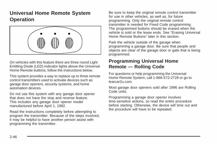
Universal Home Remote SystemOperation
On vehicles with this feature there are three round LightEmitting Diode (LED) indicator lights above the UniversalHome Remote buttons, follow the instructions below.
This system provides a way to replace up to three remotecontrol transmitters used to activate devices such asgarage door openers, security systems, and homeautomation devices.
Do not use this system with any garage door openerthat does not have the stop and reverse feature.This includes any garage door opener modelmanufactured before April 1, 1982.
Read the instructions completely before attempting toprogram the transmitter. Because of the steps involved,it may be helpful to have another person assist withprogramming the transmitter.
Be sure to keep the original remote control transmitterfor use in other vehicles, as well as, for futureprogramming. Only the original remote controltransmitter is needed for Fixed Code programming.The programmed buttons should be erased when thevehicle is sold or the lease ends. See “Erasing UniversalHome Remote Buttons” later in this section.
Park the vehicle outside of the garage whenprogramming a garage door. Be sure that people andobjects are clear of the garage door or gate that is beingprogrammed.
Programming Universal HomeRemote — Rolling CodeFor questions or help programming the UniversalHome Remote System, call 1-866-572-2728 or go tolearcar2u.com.
Most garage door openers sold after 1996 are RollingCode units.
Programming a garage door opener involvestime-sensitive actions, so read the entire procedurebefore starting. Otherwise, the device will time out andthe procedure will have to be repeated.
2-46

To program up to three devices:
1. Press START or put the vehicle in accessory mode.See Ignition Positions on page 2-24 for additionalinformation.Programming can only occur when the vehicle isrunning or in accessory mode.
2. From inside the vehicle, press the two outsidebuttons at the same time for one to two seconds,and immediately release them.
3. Locate in the garage, the garage door openerreceiver (motor-head unit). Locate the “Learn”or “Smart” button. It can usually be found where thehanging antenna wire is attached to the motor-headunit and may be a colored button. Press thisbutton. After pressing this button, complete thefollowing steps in less than 30 seconds.
2-47
4. Immediately return to the vehicle. Press and holdthe Universal Home Remote button that will beused to control the garage door until the garagedoor moves. The indicator light, above the selectedbutton, should slowly blink. This button mayneed to be held for up to 20 seconds.
5. Immediately, within one second, release the buttonwhen the garage door moves. The indicator lightblinks rapidly until programming is complete.
6. Press and release the same button again.The garage door should move, confirmingthat programming is successful and complete.
To program another Rolling Code device such as anadditional garage door opener, a security device,or home automation device, repeat Steps 1-6, choosinga different function button in Step 4 than what wasused for the garage door opener.
If these instructions do not work, the garage dooropener is probably a Fixed Code unit. Follow theProgramming instructions that follow for a Fixed Codegarage door opener.
Programming Universal HomeRemote — Fixed CodeFor questions or help programming the Universal HomeRemote System, call 1-866-572-2728 or go tolearcar2u.com.
Most garage door openers sold before 1996 are FixedCode units.
Programming a garage door opener involvestime-sensitive actions, so read the entire procedurebefore starting. Otherwise, the device will time out andthe procedure will have to be repeated.
To program up to three devices:
1. Press START or put the vehicle in accessory mode.See Ignition Positions on page 2-24 for additionalinformation.Programming can only occur when the vehicle isrunning or in accessory mode.
2-48

2. To verify that the garage door opener is a FixedCode unit, remove the battery cover on the handheld transmitter supplied by the manufacturer of thegarage door opener motor. If there are a row ofdip switches similar to the graphic above, thegarage door opener is a Fixed Code unit. If youdo not see a row of dip switches, return to theprevious section for Programming Universal HomeRemote – Rolling Code.The hand held transmitter can have betweeneight to 12 dip switches depending on the brandof transmitter.
The garage door opener receiver (motor head unit)could also have a row of dip switches that can beused when programming the Universal HomeRemote. If the total number of switches on the motorhead and hand held transmitter are different, or if thedip switch settings are different, use the dip switchsettings on the motor head unit to program theUniversal Home Remote. The motor head dip switchsettings can also be used when the original handheld transmitter is not available.
Example of Eight Dip Switches with Two Positions
2-49

The panel of switches might not appear exactly asthey do in the examples above, but they shouldbe similar.The switch positions on the hand-held transmittercould be labeled, as follows:
• A switch in the up position could be labeled as“Up,” “+,” or “On.”
• A switch in the down position could be labeledas “Down,” “−,” or “Off.”
• A switch in the middle position could be labeledas “Middle,” “0,” or “Neutral.”
3. Write down the eight to 12 switch settings from leftto right as follows:
• When a switch is in the up position, write “Left.”
• When a switch is in the down position,write “Right.”
• If a switch is set between the up and downposition, write “Middle.”The switch settings written down in Step 3now become the button strokes to be enteredinto the Universal Home Remote in Step 5.Be sure to enter the switch settings writtendown in Step 3, in order from left to right, intothe Universal Home Remote, when completingStep 5.
4. From inside the vehicle, first firmly press allthree buttons at the same time for aboutthree seconds. Release the buttons to put theUniversal Home Remote into programming mode.
Example of Eight Dip Switches with Three Positions
2-50

5. The indicator lights blink slowly. Enter each switchsetting from Step 3 into the vehicle’s UniversalHome Remote. You have two and one-half minutesto complete Step 5. Now press one button onthe Universal Home Remote for each switch settingas follows:
• If you wrote “Left,” press the left button in thevehicle.
• If you wrote “Right,” press the right button in thevehicle.
• If you wrote “Middle,” press the middle button inthe vehicle.
6. After entering all of the switch positions, again,firmly press and release all three buttons at thesame time. The indicator lights turn on.
7. Press and hold the button that will be used to controlthe garage door until the garage door moves.The indicator light above the selected button shouldslowly blink. This button may need to be held for upto 55 seconds.
8. Immediately release the button when the garagedoor moves. The indicator light blinks rapidly untilprogramming is complete.
9. Press and release the same button again.The garage door should move, confirmingthat programming is successful and complete.
To program another Fixed Code device such as anadditional garage door opener, a security device,or home automation device, repeat Steps 1-9, choosinga different button in Step 7 than what was used forthe garage door opener.
2-51

Using Universal Home RemotePress and hold the appropriate button for at least half ofa second. The indicator light comes on while thesignal is being transmitted.
Operation can occur:
• If the vehicle is in accessory mode.
• If the vehicle is in running.
• If the vehicle is in Retained Accessory Mode (RAP).See Retained Accessory Power (RAP) on page 2-25for more information.
• Up to an additional 10 minutes after RAP finishes.
• Up to 10 minutes after any door is opened.
Reprogramming Universal HomeRemote ButtonsAny of the three buttons can be reprogrammed byrepeating the instructions.
Erasing Universal Home RemoteButtonsThe programmed buttons should be erased when thevehicle is sold or the lease ends.
To erase either Rolling Code or Fixed Code on theUniversal Home Remote device:
1. Press and hold the two outside buttons at thesame time for approximately 20 seconds, untilthe indicator lights, located directly above thebuttons, begin to blink rapidly.
2. Once the indicator lights begin to blink, release bothbuttons. The codes from all buttons are erased.
For help or information on the Universal Home RemoteSystem, call the customer assistance phone numberunder Customer Assistance Offices on page 8-6.
2-52

Storage Areas
Glove BoxLift the glovebox handle up to open it. Use the key tolock and unlock the glovebox.
CupholdersThe cupholders are located under a lid in the frontconsole to the right of the shift lever. Press the left sideof the lid and it will open automatically.
Center Console StorageThere is a center console storage area located betweenthe seats. To open this storage area, push the latchbutton and lift the lid.
There is also an upright center console storage areabetween the seatbacks. To open the storage area, pressand release the button near the top so it extends out.Then, turn the button in either direction to unlatch the lidand pull the console lid down. After closing the lid,press the release button back in.
Floor MatsThe driver side floor mat is held in place by two snapsand the passenger side is held in place by one.To remove the floor mats, pull up on the rear of themat to disconnect from the snaps. To reinstall, line upthe openings in the floor mat over the snaps and pushdown into place.
Be sure that the driver side floor mat is properly placedon the floor so that it does not block the movementof the accelerator pedal.
2-53

Rear Storage Area
There is a cargo divider located in the trunk to keepcargo from getting in the way of the retractable hardtop.The cargo divider must be in place for the top to move.
To install the cargo divider, snap the bottom of thedivider onto the snaps (B) located on the floor of thetrunk. Then, pull the divider up and place the pinson each side of the divider into the notches (A) on eitherside of the trunk.
There is also a storage compartment located in thetrunk on the passenger side.
To access the storage compartment, unsnap the lid.To reinstall the lid, line up the opening in the lid over thesnap and push down into place.
Convenience NetUse the convenience net, located in the rear, to storesmall loads as far forward as possible. The netshould not be used to store heavy loads.
Retractable HardtopThe following procedures explain the proper operationof the retractable hardtop. The retractable hardtopwill not operate if the valet lockout switch is on.
If the retractable hardtop is lowered or raised multipletimes, the engine should be running while doing soto prevent drain on the vehicle’s battery.
{CAUTION:
When the retractable hardtop is opened or closed,people can be injured by the parts that move: thehardtop and its mechanism, the trunk lid, and theside windows. Keep people away from these partswhen you are lowering or raising the top.
2-54

Lowering the Retractable HardtopNotice: Leaving the retractable hardtop down andexposing the interior of the vehicle to outdoorconditions may cause damage. Always close theretractable hardtop if leaving the vehicle outdoors.
1. Park on a level surface and shift the transmissioninto P (Park).
2. The vehicle’s engine must be on or in Acc.
3. Lower both sun visors.
Notice: Raising or lowering the top while the vehicleis in motion can cause damage to the top or topmechanism. Make sure the vehicle is in P (Park) tolower or raise the top.
Notice: Lowering the top if it is damp, wet, or dirtycan cause stains, mildew, and damage to the insideof your vehicle. Dry off the top before lowering it.
4. Make sure that nothing or no one is on or aroundthe top. Make sure the trunk cargo cover is inplace with nothing on top or in front of the cargocover. See Rear Storage Area on page 2-54for more information. Also, make sure the valetlockout switch is off.
5. Push and hold thebottom of this buttonlocated on the consolebehind the shifter lever.
The windows will automatically lower and the top willautomatically lower into the storage area. A chimewill sound when the top has lowered completely.
If the radio is on, the sound may be muted briefly whilethe retractable top is lowered. This occurs becausea new audio system equalization is being loaded.
Under certain conditions, the Driver Information Center(DIC) may display messages regarding the retractablehardtop. See DIC Warnings and Messages on page 3-60for more information.
If the retractable hardtop does not operate, and thereare no messages displayed on the Driver InformationCenter (DIC), then perform the “Power Window Initialize”steps under Power Windows on page 2-18.
2-55

Raising the Retractable Hardtop1. Park on a level surface. Shift the transmission into
P (Park).
2. The vehicle’s engine must be on or in Acc.
3. Lower both sun visors.
Notice: Raising or lowering the top while the vehicleis in motion can cause damage to the top or topmechanism. Make sure the vehicle is in P (Park) tolower or raise the top.
4. Make sure nothing or no one is on or around thetop. Make sure the trunk cargo cover is in placewith no cargo on top of or in front of the cargocover. See Rear Storage Area on page 2-54 formore information. Also, be sure the valet lockoutswitch is off.
5. Push and hold the topof this button locatedbehind the shift lever.
The windows will automatically lower and the top willraise. A chime will sound when the top has raisedcompletely.
After the top is fully raised, release the retractablehardtop button.
If the radio is on, you may notice a brief mute in sound.This is normal and due to a new audio systemequalization being loaded for the vehicle with the topraised.
Under certain conditions, the Driver InformationCenter (DIC) may display messages regarding theretractable hardtop. See DIC Warnings and Messageson page 3-60 for more information.
2-56

If the retractable hardtop does not operate, and thereare no messages displayed on the Driver InformationCenter (DIC), then perform the “Power Window Initialize”steps under Power Windows on page 2-18.
Manually Raising the Retractable HardtopIf the vehicle has a power loss, such as a deadbattery, you can still raise the top manually by doing thefollowing:
1. Lower both sun visors and open both doors.
2. Use the key to open the trunk. See Keys onpage 2-3 and Trunk on page 2-14 for moreinformation.
3. Raise the trunk by hand.
4. Find the hydraulic pumpunder the carpet onthe rear driver sideof the trunk. Open thevalve by turning itcounterclockwise withyour hand until it stops.
Notice: Pressing the retractable hardtop buttonwhen the hydraulic pump valve is open coulddamage the pump. Always close the hydraulic pumpvalve after the retractable hardtop has been closedmanually.
5. Pull both sides of the rear tonneau over-center linkdown to unlock the linkage.
2-57

6. Move the rear tonneau rearward and up to the storedposition. Pull from the center of the tonneau to keeppressure even. The rubber bumper on each cornerwill fit against the underside of the trunk decklid.
7. Push both sides of the rear tonneau over-center linkup until they stop to lock the linkage.
8. Close the hydraulic pump valve by turning itclockwise with your hand until it stops.
2-58

9. Remove the upright center storage compartment.Use the wrench to remove the four screws holdingthe storage area in place.
10. Reach behind the square hole and push the fronttonneau over-center link up. The front tonneaushould pull up easily. If it does not, push theover-center link up more.
2-59

11. Manually move the front tonneau to the openposition. Once the front tonneau is open, foldthe side wings by gently pressing them in. Do notforce the wings. If they are hard to move, make surethe front tonneau is open all the way.
12. Reach in from the side of the vehicle and under thetop to remove the headliner plug. The plug will belocated in the center of the top near the front.
13. Insert the wrench into the bolt beneath the pluglocation. Turn the wrench about one-quarter turncounterclockwise until it stops while gently pulling upon the center of the top to release it.
2-60

14. Hold the top in the front and side and lift the top outof the stored position.
15. Hold the top in the front and the rear and lift the topuntil it is almost closed. Be careful not to pinch yourfingers between the rear of the top and the rearwindow.
2-61
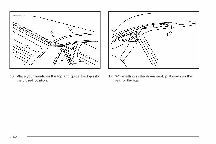
16. Place your hands on the top and guide the top intothe closed position.
17. While sitting in the driver seat, pull down on therear of the top.
2-62

18. While holding the rearof the top down, insertthe wrench into thebolt in the plug openingin the headliner.
Turn the wrenchcounterclockwiseuntil it stops to fullyopen the latchjaws around the pins.
19. Pull down on the roof with the latch turned open.Turn the wrench clockwise until it stops to lock thetop into position. Push up on the roof. If it movesaway from the windshield header it is not latchedand you will need to repeat the previous steps.
20. From outside the vehicle, push down on both rearcorners of the top to make sure it is completelylocked into place.
21. From inside the vehicle, reach behind the headrestand gently pull the wings out a small amount.Then, fold the front tonneau to the closed position.
22. Manually close the trunk.
2-63

✍ NOTES
2-64

Instrument Panel Overview ...............................3-4Hazard Warning Flashers ................................3-6Horn .............................................................3-6Power Tilt Wheel and Telescopic Steering
Column ......................................................3-6Heated Steering Wheel ...................................3-7Turn Signal/Multifunction Lever .........................3-7Turn and Lane-Change Signals ........................3-7Headlamp High/Low-Beam Changer ..................3-8Flash-to-Pass .................................................3-8Windshield Wipers ..........................................3-8Rainsense™ Wipers .......................................3-9Windshield Washer .......................................3-10Headlamp Washer ........................................3-11Cruise Control ..............................................3-11Adaptive Cruise Control .................................3-14Exterior Lamps .............................................3-26Wiper Activated Headlamps ............................3-27
Headlamps on Reminder ................................3-27Daytime Running Lamps (DRL) .......................3-27Adaptive Forward Lighting System ...................3-28Fog Lamps ..................................................3-28Twilight Sentinel® ..........................................3-29Exterior Lighting Battery Saver ........................3-30Instrument Panel Brightness ...........................3-30Courtesy Lamps ...........................................3-30Entry/Exit Lighting .........................................3-30Reading Lamps ............................................3-30Battery Run-Down Protection ..........................3-31Head-Up Display (HUD) .................................3-31Accessory Power Outlet(s) .............................3-34Ashtray(s) and Cigarette Lighter ......................3-35
Climate Controls ............................................3-36Dual Climate Control System ..........................3-36Outlet Adjustment .........................................3-40Passenger Compartment Air Filter ...................3-41
Section 3 Instrument Panel
3-1

Warning Lights, Gages, and Indicators ............3-41Instrument Panel Cluster ................................3-42Speedometer and Odometer ...........................3-43Trip Odometer ..............................................3-43Tachometer .................................................3-43Safety Belt Reminders ...................................3-44Airbag Readiness Light ..................................3-44Passenger Airbag Status Indicator ...................3-45Charging System Light ..................................3-46Voltmeter Gage ............................................3-46Brake System Warning Light ..........................3-47Antilock Brake System (ABS) Warning Light .....3-48StabiliTrak®/Traction Control System (TCS)
Warning Light ...........................................3-48Engine Coolant Temperature Gage ..................3-49Tire Pressure Light .......................................3-50Malfunction Indicator Lamp .............................3-50Engine Oil Pressure Gage .............................3-54Security Light ...............................................3-55Fog Lamp Light ............................................3-55
Lights On Reminder ......................................3-55Highbeam On Light .......................................3-55Fuel Gage ...................................................3-56
Driver Information Center (DIC) .......................3-57DIC Operation and Displays ...........................3-57DIC Warnings and Messages .........................3-60Other Messages ...........................................3-70DIC Vehicle Personalization ............................3-72
Trip Computer ................................................3-76Oil Life Indicator ...........................................3-76
Audio System(s) .............................................3-76Bluetooth® ...................................................3-77Theft-Deterrent Feature ..................................3-88Audio Steering Wheel Controls .......................3-88Radio Reception ...........................................3-90Care of Your CDs .........................................3-91Care of the CD Player ...................................3-91Diversity Antenna System ..............................3-91XM™ Satellite Radio Antenna System .............3-91
Section 3 Instrument Panel
3-2

✍ NOTES
3-3

Instrument Panel Overview
XLR shown, XLR-V similar
3-4

The main components of the instrument panel are the following:
A. Head-Up Display (HUD) on page 3-31 or InstrumentPanel Brightness on page 3-30.
B. Turn Signal/Multifunction Lever on page 3-7. CruiseControl on page 3-11. Exterior Lamps on page 3-26.Fog Lamps on page 3-28.
C. Instrument Panel Cluster on page 3-42.D. Windshield Wipers on page 3-8 and Windshield
Washer on page 3-10.E. Driver Information Center (DIC) Controls/Interior
Lamps. See DIC Operation and Displays onpage 3-57.
F. Outlet Adjustment on page 3-40.G. Hazard Warning Flashers on page 3-6.H. Audio Steering Wheel Controls on page 3-88.
Adaptive Cruise Control on page 3-14 (If Equipped).Heated Steering Wheel on page 3-7. VoiceCommands. See OnStar® System on page 2-42.
I. Power Tilt Wheel and Telescopic Steering Columnon page 3-6.
J. Horn on page 3-6.K. Ignition Positions on page 2-24.L. Shift Lever. See Automatic Transmission Operation
on page 2-28.M. Traction Control System (TCS) on page 5-8.N. Retractable Hardtop on page 2-54.O. Cupholders on page 2-53.P. Cigarette Lighter. See Ashtray(s) and Cigarette
Lighter on page 3-35.Q. Dual Climate Control System on page 3-36.R. Audio/Navigation System. See Navigation System
Overview on page 4-2.S. Glove Box on page 2-53.
3-5

Hazard Warning FlashersThe hazard warning flashers warns others that you havea problem. The button is located near the center ofthe instrument panel.
| : Press to make the front and rear turn signal lampsflash on and off. Press again to turn the flashers off.
The hazard warning flashers work no matter what modethe ignition is in, even if the ignition is turned off.
When the hazard warning flashers are on, the turnsignals will not work.
HornPress near or on the horn symbols on the steeringwheel pad to sound the horn.
Power Tilt Wheel and TelescopicSteering Column
The power tilt andtelescope wheel control islocated on the outboardside of the steeringcolumn.
To operate the power tilt feature, push the control upand the steering wheel tilts up. Push the controldown and the steering wheel goes down.
Push the control forward and the steering wheel movestoward the front of the vehicle. Push the control rearwardand the steering wheel moves toward the rear of thevehicle. To set the memory position, see DIC VehiclePersonalization on page 3-72 and Memory Seat, Mirrorsand Steering Wheel on page 1-3.
3-6

Heated Steering WheelFor vehicles with a heated steering wheel, the button forthis feature is located on the steering wheel.
( : Press to turn the heated steering wheel on or off.A light on the button displays when the feature isturned on.
The steering wheel takes about three minutes to startheating.
Turn Signal/Multifunction Lever
The lever on the left side of the steering columnincludes the following:
G : Turn and Lane-Change Signals
3 : Headlamp High/Low-Beam Changer
# : Fog Lamps
I : Cruise Control
P : Exterior Lamps Control
• Flash-to-Pass Feature. See Flash-to-Pass onpage 3-8.
Information for these features is on the pages following.
Turn and Lane-Change SignalsAn arrow on the instrumentpanel cluster flashes in thedirection of the turn orlane change.
Move the multifunction lever all the way up or down tosignal a turn.
Raise or lower the lever until the arrow starts to flash tosignal a lane change. Hold it there until the lanechange is complete.
The lever returns to its starting position whenever it isreleased.
3-7

If after signaling a turn or a lane change the arrowsflash rapidly or do not come on, a signal bulb could beburned out.
Have the bulbs replaced. If the bulb is not burned out,check the fuses. See Fuses and Circuit Breakerson page 6-83.
Turn Signal on ChimeA chime will remind you if the turn signal is left on formore than 3/4 mile (1.2 km) of driving.
If you need to leave the turn signal on for more than3/4 mile (1.2 km), turn off the signal and then turn itback on.
Headlamp High/Low-Beam ChangerPush the turn signal lever all the way forward tochange the headlamps from low beam to high beam.
When the high beams are on, this light $ appears onthe instrument panel cluster.
Pull the lever rearward to change the headlamps backto low beam.
Flash-to-PassThis feature lets you use the high-beam headlamps tosignal the driver in front of you that you want to pass.Pull and hold the turn signal lever toward you to use.When you do, the following will occur:
• If the low-beam headlamps are on, the high-beamheadlamps will turn on. They will stay on as long asyou hold the lever there. Release the lever to turnthem off.
• If the headlamps are on high-beam, they will switchto low-beam. To return to high beam, push the leveraway from you.
Windshield Wipers
The windshield wiper lever is located on the right side ofthe steering column.
3-8

Move the lever to the following positions:
1 (High Speed): For steady wiping at high speed.
6 (Low Speed): For steady wiping at low speed.
& (Delay): Use to set a delay between wipes.
x (Delay Adjustment): Use for a delayed wipingcycle. Turn the intermittent adjust band down fora longer delay or up for a shorter delay. The wiperspeed can only be manually adjusted when the leveris in this position.
9 (Off): Turns off the windshield wipers.
8 (Mist): Move all the way down to mist and releasefor a single wiping cycle. The windshield wipers willstop after one wipe. Hold the band on mist longer formore wipes.
Heavy snow or ice can overload the wipers. If this occurs,a circuit breaker will stop the wipers until the motor cools.Clear all ice and snow from the windshield wiper bladesbefore using them. If the wiper blades are frozen to thewindshield, carefully loosen them or warm the windshieldbefore turning the wipers on. If they become worn ordamaged, get new blades or blade inserts.
Rainsense™ WipersWith Rainsense wipers, there is a moisture sensormounted on the interior side of the windshield belowthe rearview mirror, and it automatically operates thewipers by monitoring the amount of moisture build-upon the windshield. Wipes occur as needed to clear thewindshield depending on driving conditions and thesensitivity setting. In light rain or snow, fewer wipes willoccur. In heavy rain or snow, wipes will occur morefrequently. The Rainsense wipers operate in a delaymode as well as a continuous low or high speed asneeded. If the system is left on for long periods of time,occasional wipes may occur without any moisture onthe windshield. This is normal and indicates that theRainsense system is activated.
The Rainsense system is also sensitive to vibration.The system may activate if something hits thewindshield or if the vehicle hits a bump.
The Rainsense system can be activated by moving thewiper lever up to the delay position and turning thedelay adjust band to one of the five sensitivity levels.The bottom delay adjust position is the lowest sensitivitysetting, level one. This allows more rain or snow tocollect on the windshield between wipes. Turning thedelay adjust band away from you to the higher sensitivitylevels allows less rain or snow to collect on thewindshield between wipes.
3-9

The top position is the highest sensitivity setting, levelfive. A single wipe will occur each time the delay adjustband is turned to a higher sensitivity level to indicatethat the sensitivity level has been increased.
Notice: Going through an automatic car wash withthe wipers on can damage them. Turn the wipersoff when going through an automatic car wash.
The mist and wash cycles operate as normal and arenot affected by the Rainsense function. The Rainsensesystem can be overridden at any time by manuallychanging the wiper control to low or high speed.
When Rainsense is active, the headlamps will turnon automatically. If it is dark, they will remain on.See “Wiper-Activated Headlamps” under ExteriorLamps on page 3-26 for more information.
Notice: Do not place stickers or other items onthe exterior glass surface directly in front ofthe moisture sensor. Doing this could cause themoisture sensor to malfunction.
Windshield WasherK (Washer Fluid): The lever on the right side of thesteering column also controls the windshield washer.There is a button at the end of the lever. To spraywasher fluid on the windshield, press the button andhold it. The washer will spray until you release thebutton. The wipers will continue to clear the windowfor about six seconds after the button is released andthen stop or return to your preset speed.
{CAUTION:
In freezing weather, do not use your washer untilthe windshield is warmed. Otherwise the washerfluid can form ice on the windshield, blocking yourvision.
If the fluid in the windshield washer fluid reservoir islow, the message LOW WASHER FLUID will appearon the Driver Information Center (DIC) display. Itwill take 60 seconds after the bottle is refilled for thismessage to turn off. For information on the correctwasher fluid mixture to use, see Windshield WasherFluid on page 6-31 and Recommended Fluids andLubricants on page 7-11.
3-10

Headlamp WasherThe headlamps washer only functions every fourth timethe washer button is pressed and if the headlampsare on.
Cruise ControlWith cruise control, a speed of about 25 mph (40 km/h)or more can be maintained without keeping your footon the accelerator. Cruise control does not workat speeds below about 25 mph (40 km/h).
Cruise control will not work if the parking brake is set, orif the master cylinder brake fluid level is low.
{CAUTION:
Cruise control can be dangerous where you cannotdrive safely at a steady speed. So, do not use thecruise control on winding roads or in heavy traffic.
Cruise control can be dangerous on slippery roads.On such roads, fast changes in tire traction cancause excessive wheel slip, and you could losecontrol. Do not use cruise control on slippery roads.
If the vehicle has the traction control system and itbegins to limit wheel spin while cruise control is on,the cruise control will automatically disengage.See Traction Control System (TCS) on page 5-8.When road conditions allow cruise control to be safelyused again, it can be turned back on.
9 (Off): Turns the system off.
R (On): Turns the system on.
+ (Resume/Accelerate): Makes the vehicle accelerateor resume to a previously set speed.
T (Set): Press this button at the end of the lever toset the speed.
3-11
Setting Cruise Control
{CAUTION:
If you leave your cruise control on when you arenot using cruise, you might hit a button and gointo cruise when you do not want to. You could bestartled and even lose control. Keep the cruisecontrol switch off until you want to use cruisecontrol.
1. Move the cruise control switch to on.
2. Get up to the speed desired.
3. Press the set button at the end of the lever andrelease it.
4. Take your foot off the accelerator pedal.
This light J appears on the instrument panel clusterwhen the cruise control is engaged.
Resuming a Set SpeedIf the cruise control is set at a desired speed andthe brake is applied, the cruise control will turn off.It does not need to be reset
Once the vehicle is going about 25 mph (40 km/h) ormore, move the cruise control switch briefly from R to S .
The vehicle will go back up to the chosen speed andstay there.
If the switch is held at resume/accelerate the vehiclewill keep going faster until the switch is released orthe brake is applied. Do not hold the switch atresume/accelerate, unless you want the vehicle togo faster.
3-12

Increasing Speed While Using CruiseControlThere are two ways to increase speed:
• Use the accelerator pedal to get to the higherspeed. Press T at the end of the lever, thenrelease the button and the accelerator pedal.The vehicle will now cruise at the higher speed.If the accelerator pedal is held longer than60 seconds, cruise control will turn off.
• Move the cruise switch from R to S . Hold it thereuntil the desired speed is reached, and thenrelease the switch. To increase the vehicle speedin small amounts, move the switch briefly toresume/accelerate. Each time this is done, thevehicle goes about 1 mph (1.6 km/h) faster.
Reducing Speed While Using CruiseControl• Press and hold the set button until the lower speed
desired is reached, then release it.
• To slow down in small amounts, briefly press theset button. Each time this is done, the vehiclegoes about 1 mph (1.6 km/h) slower.
Passing Another Vehicle While UsingCruise ControlUse the accelerator pedal to increase the vehicle speed.When you take your foot off the pedal, the vehicleslows down to the cruise control speed set earlier.
Using Cruise Control on HillsHow well your cruise control works on hills dependsupon the vehicle speed, load and the steepness of thehills. When going up steep hills, you might have tostep on the accelerator pedal to maintain your speed.When going downhill, you might have to brake or shiftto a lower gear to keep your vehicle’s speed down.When the brakes are applied the cruise control turns off.
Ending Cruise ControlThere are two ways to turn off the cruise control:
• Step lightly on the brake pedal
• Move the cruise control switch to 9
Erasing Speed MemoryThe cruise control set speed memory is erased whenthe cruise control or the ignition is turned off.
3-13

Adaptive Cruise ControlIf the vehicle has this feature, be sure to read this entiresection before using it.
The system operates on a radio frequency subject toFederal Communications Commission (FCC) Rules andwith Industry Canada.
This device complies with Part 15 of the FCC Rules.Operation is subject to the following two conditions:
1. This device may not cause interference.
2. This device must accept any interference received,including interference that may cause undesiredoperation of the device.
This device complies with RSS-210 of Industry Canada.Operation is subject to the following two conditions:
1. This device may not cause interference.
2. This device must accept any interference received,including interference that may cause undesiredoperation of the device.
Changes or modifications to this system by other thanan authorized service facility could void authorization touse this equipment.
Adaptive Cruise Control is an enhancement to traditionalcruise control and is not a safety system. It allowsyou to keep cruise control engaged in moderate trafficconditions without it having to be constantly reset.Adaptive Cruise Control uses radar to detect a vehicledirectly ahead in your path, within a distance of328 ft (100 m), and operates at speeds above25 mph (40 km/h). When it is engaged by the driver,the system can apply limited braking or accelerationof the vehicle, automatically, to maintain a selectedfollowing distance to the vehicle ahead. The vehicle’sbraking during Adaptive Cruise Control is comparable toa person applying moderate pressure to the vehicle’sbrake pedal. To disengage Adaptive Cruise Control,apply the brake. If no vehicle is in your path, yourvehicle will react like traditional cruise control.
3-14

{CAUTION:
Adaptive Cruise Control will not apply hard brakingor bring the vehicle to a complete stop. It will notrespond to stopped vehicles, pedestrians oranimals. When you are approaching a vehicle orobject, Adaptive Cruise Control may not have timeto slow your vehicle enough to avoid a collision.Your complete attention is always required whiledriving and you should be ready to take actionand apply the brakes. For more information,see Defensive Driving on page 5-2.
{CAUTION:
• On winding roads, Adaptive Cruise Controlmay not detect a vehicle ahead. You couldcrash into a vehicle ahead of you. Do not useAdaptive Cruise Control on winding roads.
CAUTION: (Continued)
CAUTION: (Continued)
• Adaptive Cruise Control may not have time toslow your vehicle enough to avoid a crashwhen you are driving in conditions wherevehicles may suddenly slow or stop ahead ofyou, enter your lane, or cross your vehicle’spath. If you are driving in these conditions, donot use Adaptive Cruise Control. The warningbeep and alert symbol may indicate thatyou are driving in conditions where AdaptiveCruise Control should not be used.See “Alerting the Driver” in this section.
• On slippery roads, fast changes in tire tractioncan cause needless wheel spinning, and youcould lose control. Do not use cruise controlon slippery roads.
• When weather limits visibility, such as when infog, rain, or snow conditions, Adaptive CruiseControl performance is limited. There may notbe enough distance to adapt to the changingtraffic conditions. Do not use cruise controlwhen visibility is low.
3-15
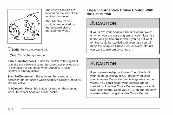
The cruise controls arelocated on the end of themultifunction lever.
The Adaptive Cruisecontrols are located onthe outboard side ofthe steering wheel.
9 (Off): Turns the system off.
R (On): Turns the system on.
S (Resume/Increase): Push the switch to this symbolto make the vehicle resume the speed set previously orto increase the set speed when Adaptive CruiseControl is already active.
T (Set/Decrease): Press to set the speed or todecrease the set speed when Adaptive Cruise Control isalready active.
[ (Cancel): Press this button located on the steeringwheel to cancel Adaptive cruise control.
Engaging Adaptive Cruise Control Withthe Set Button
{CAUTION:
If you leave your Adaptive Cruise Control switchon when you are not using cruise, you might hit abutton and go into cruise when you do not wantto. You could be startled and even lose control.Keep the Adaptive Cruise Control switch off untilyou want to use cruise control.
{CAUTION:
If you operate Adaptive Cruise Control withoutyour Head-up Display (HUD) properly adjusted,your Adaptive Cruise Control settings may not bevisible. You could forget your settings and bestartled by Adaptive Cruise Control response andeven lose control. Keep your HUD on and properlyadjusted when using Adaptive Cruise Control.
3-16

The set speed is selected by the driver. This is thespeed you will travel if there is no vehicle detected inyour path.
To set Adaptive Cruise Control, do the following:
1. Make sure the Head-Up Display (HUD) is on andproperly adjusted. You cannot engage AdaptiveCruise Control unless the HUD is on. See Head-UpDisplay (HUD) on page 3-31 for more information.
2. Move the switch to the on position.
3. Get up to the desired speed.
4. Press T at the end of the lever and releasethe button.
5. Take your foot off the accelerator pedal.
Once Adaptive Cruise Control is set, it mightimmediately apply the brakes if it detects a vehicleahead that is too close or moving slower than yourvehicle.
This symbol appears onthe Head-Up Display(HUD) to indicate thatAdaptive Cruise Controlis active.
See Head-Up Display (HUD) on page 3-31 for moreinformation.
Make sure the set speed is visible on the HUD so youknow the speed your vehicle will accelerate to if avehicle is not detected in your path. Keep in mindspeed limits, surrounding traffic speeds, and weatherconditions when adjusting your set speed.
If the vehicle is in Adaptive Cruise Control when thetraction control system begins to limit wheel spin,the Adaptive Cruise Control automatically disengages.See Traction Control System (TCS) on page 5-8and StabiliTrak® System on page 5-6. When roadconditions allow you to safely use it again, the AdaptiveCruise Control can be turned back on.
3-17

Increasing Set Speed While Using AdaptiveCruise ControlThere are two ways to increase the set speed:
• Use the accelerator to get to the higher speed.Press T at the end of the lever, then releasethe button and the accelerator pedal. The vehiclewill now cruise at the higher speed.
• Move the Adaptive Cruise Control switch fromR to S . Hold it there until the desired set speedis displayed in the HUD, then release the switch.To increase the set speed in small amounts, movethe switch briefly to resume/increase. Each timethis is done, the vehicle set speed increasesby about 1 mph (1.6 km/h).
Your vehicle will not reach the set speed until thesystem determines there is no vehicle in front of you.At that point, your vehicle speed will increase to theset speed.
Decreasing Set Speed While UsingAdaptive Cruise ControlPress T on the end of the lever until the lowerdesired speed is reached, then release the button.
To slow down in small amounts, briefly press T .Each this is done, the set speed will be 1 mph (1.6 km/h)slower.
Resuming a Set SpeedIf the brakes are applied while the Adaptive CruiseControl is at a set speed, this disengages the AdaptiveCruise Control. But it does not need to be reset.
Once the vehicle reaches about 25 mph (40 km/h) ormore, move the Adaptive Cruise Control switchbriefly from R to S . Adaptive Cruise Control will beengaged with the speed selected previously.
3-18

Selecting the Follow Distance (GAP)When the system detects a slower moving vehicle, it willadjust your vehicle’s speed and maintain the followingdistance (gap) selected.
Use the GAP button onthe steering wheel toadjust the follow distancebetween your vehicleand other vehicles.
Press the top of the button to increase the distance orthe bottom of the button to decrease the distance.The first button press shows the current follow distancesetting on the HUD. The current following distancesetting is maintained until it is changed.
There are six follow distances to choose from.The follow distance selection ranges from near to far(1 second to 2 seconds follow time). The distancemaintained for a selected follow distance varies basedon vehicle speed. The faster the vehicle speed the
further back you will follow. Consider traffic andweather conditions when selecting the follow distance.The range of selectable distances may not beappropriate for all drivers and driving conditions. If youprefer to travel at a following distance farther thanAdaptive Cruise Control allows, disengage the systemand drive manually.
A graphic on the HUD indicates the selected followingdistance. This picture shows a maximum follow distance.The vehicles will move closer together as you select asmaller following distance.
3-19

Alerting the DriverThis symbol flashes on theHUD and a warning beepsounds when driveraction is required.
Driver action is required when:
• Adaptive Cruise Control cannot apply sufficientbraking because you are approaching a vehicletoo rapidly.
• The vehicle speed drops below about20 mph (32 km/h).
• A temporary condition prohibits Adaptive CruiseControl from operating. See DIC Warnings andMessages on page 3-60 for more information.
• A malfunction is detected in the system. See DICWarnings and Messages on page 3-60 for moreinformation.
See Defensive Driving on page 5-2.
{CAUTION:
Adaptive Cruise Control has only limited brakingability to slow your vehicle. In some cases,Adaptive Cruise Control may not have time to slowyour vehicle enough to avoid a collision. Be readyto take action and apply the brakes yourself.See Defensive Driving on page 5-2.
Approaching and Following a VehicleThis symbol only appearson the HUD when avehicle ahead is detectedin your path.
If this symbol does not appear, or disappears briefly,Adaptive Cruise Control will not respond to vehicles youmay see ahead.
3-20

{CAUTION:
When the Adaptive Cruise Control radar is blockedby snow, ice, or dirt, it may not detect a vehicleahead. Adaptive Cruise Control may not have timeto slow your vehicle enough to avoid a collision.Do not use Adaptive Cruise Control when theradar is blocked by snow, ice, or dirt. Keep yourradar clean. See “Cleaning the System” later inthis section.
Adaptive Cruise Control automatically slows the vehicledown when approaching a slower moving vehicle.It then adjusts your speed to follow the vehicle in frontat the selected following distance. Your speed increasesor decreases to follow the vehicle in front of you, butwill not exceed the set speed. It may apply limitedbraking, if necessary. When braking is active, the brakelights come on. It may feel or sound different than ifyou were applying the brakes yourself. This is normal.
Stationary or Very Slow-Moving Objects
{CAUTION:
Adaptive Cruise Control may not detect and reactto stationary or slow-moving vehicles or otherobjects ahead of you. You could crash into anobject ahead of you. Do not use Adaptive CruiseControl when approaching stationary orslow-moving vehicles or other objects.
{CAUTION:
Adaptive Cruise Control may not detect and reactto stationary or slow-moving vehicles or otherobjects ahead of you. Your vehicle may acceleratetoward objects, such as a stopped vehicle thatsuddenly appears after the lead vehicle changeslanes. Your complete attention is always requiredwhile driving and you should be ready to takeaction and apply the brakes.
3-21

Low-Speed DeactivationIf your speed falls below 20 mph (32 km/h) whilefollowing a vehicle ahead, Adaptive Cruise Controlbegins to disengage. The driver alert symbol onthe HUD flashes and the warning beep sounds.The driver must take action since Adaptive CruiseControl will not slow the vehicle to a stop.
Passing a VehicleTo increase speed to pass a vehicle, use the acceleratorpedal. While your foot is on the accelerator pedal, thesystem will not automatically apply the brakes. Onceyou pass the vehicle and remove your foot fromthe accelerator pedal, Adaptive Cruise Control returnsto normal operation and the brakes can be applied,if needed.
{CAUTION:
If you rest your foot on the accelerator pedal, thesystem will not automatically apply the brakes.You could crash into a vehicle ahead of you.Do not rest your foot on the accelerator pedalwhen using Adaptive Cruise Control.
Curves in the Road
{CAUTION:
Due to Adaptive Cruise Control limitations incurves, it may respond to a vehicle in anotherlane, or may not have time to react to a vehicle inyour lane. You could crash into a vehicle ahead ofyou, or lose control of your vehicle. Give extraattention in curves and be ready to use the brakesif necessary. Select an appropriate speed whiledriving in curves.
Adaptive Cruise Control might operate differently in asharp curve. It might reduce your speed if the curve istoo sharp. The TIGHT CURVE message will also displayon the HUD. See Head-Up Display (HUD) on page 3-31for more information.
3-22

When following a vehicle and entering a curve, AdaptiveCruise Control could lose track of the vehicle in yourlane and accelerate your vehicle. When this happens,the vehicle ahead symbol will not appear on the HUD.
Adaptive Cruise Control might detect a vehicle that isnot in your lane and apply the brakes.
Adaptive Cruise Control might occasionally providea driver alert and/or braking that you considerunnecessary. It could respond to signs, guardrails,and other stationary objects when entering or exitinga curve. This is normal operation. Your vehicle does notneed service.
3-23

Highway Exit Ramps
{CAUTION:
Adaptive Cruise Control may lose track of thevehicle ahead and accelerate up to your set speedwhile entering or on highway exit ramps. You couldbe startled by this acceleration and even losecontrol of the vehicle. Disengage Adaptive CruiseControl before entering a highway exit ramp. Do notuse Adaptive Cruise Control while entering or onexit ramps.
Other Vehicle Lane Changes
If another vehicle enters the same lane as you, AdaptiveCruise Control will not detect the vehicle until it iscompletely in the lane. Be ready to take action and applythe brakes yourself.
Using Adaptive Cruise Controls on Hills
How well Adaptive Cruise Control works on hillsdepends on your speed, vehicle load, traffic conditions,and the steepness of the hills. It might not detect avehicle in your lane while driving on hills. While goingup steep hills, you might want to use the acceleratorpedal to maintain your vehicle speed. While goingdownhill, you might have to brake to keep your vehiclespeed down. Applying the brake disengages thesystem. You may choose not to use Adaptive CruiseControl on steep hills.
Disengaging Adaptive Cruise ControlApply the brake pedal or move the Adaptive CruiseControl switch to off, to disengage the system. AdaptiveCruise Control information does not appear on theHUD while the system is not engaged.
3-24

Erasing Set Speed MemoryThe set speed memory is erased when the AdaptiveCruise Control switch or the ignition is turned off.
Other MessagesThere are three messages that may appear on the DIC.They are SERVICE RADAR CRUISE, CRUISE NOTREADY and CLEAN RADAR CRUISE. These messageswill only appear to indicate a problem with the AdaptiveCruise Control. See DIC Warnings and Messageson page 3-60 for more information.
You may also see CRUISE SPEED LIMITED displayedin the HUD. See Head-Up Display (HUD) on page 3-31for more information.
Cleaning the SystemThe radar can become blocked by snow, ice, or dirt.If so, you may need to turn off the engine and clean thelens, located on the driver side of the front fascia.
Clean the surface with a 50/50 mixture of isopropylalcohol and water on a dampened cloth. After cleaningthe fascia lens, try to engage Adaptive Cruise Control.If this does not fix the problem, you may have to removethe fascia lens and clean the inside of the fascia lensand radar lens.
To clean the inside of the fascia lens and radar lens,insert a tool into one of the small slots on the inboardside of the lens and pop the lens out. Clean the surfacewith a 50/50 mixture of isopropyl alcohol and wateron a dampened cloth. After cleaning the lens, set thelens back in place and press until it snaps in place.
3-25

Exterior Lamps
The exterior lamp control is located to the left of thesteering wheel on the multifunction lever.
O (Exterior Lamp Control): Turn the band to operatethe exterior lamps.
There are four positions:
O (Off): Turns off all lamps.
AUTO (Automatic): Sets the exterior lamps toautomatic mode. AUTO mode will turn the exteriorlamps on and off depending on how much lightis available outside the vehicle. Turning the band toAUTO mode also enables the Adaptive Forward Lightingsystem. See Adaptive Forward Lighting System onpage 3-28.
To override AUTO mode, turn the control to off.
To reset to AUTO mode turn the control to exteriorlamps and then back to AUTO. Automatic mode will alsoreset when your vehicle is turned off and then backon again when the control is left in the AUTO position.
See Twilight Sentinel® on page 3-29.
; (Parking Lamp): Turns on the parking lampstogether with the following:
• Sidemarker Lamps
• Taillamps
• License Plate Lamps
• Instrument Panel Lights
The parking brake indicator light will come on and stayon when the parking lamps are on with the engineoff and the ignition to ACC/ACCESSORY.
5 (Headlamps): Turns on the headlamps, togetherwith the previously listed lamps and lights.
3-26

Wiper Activated HeadlampsThis feature activates the headlamps and parking lampsafter the windshield wipers have been in use forapproximately six seconds and the multifunction lever isin the AUTO position. See Exterior Lamps on page 3-26.
When the exterior lamp control has been turned off or isin the parking lamp position and the wiper control ison delay, low speed or high speed, the HEADLAMPSSUGGESTED message will appear on the DriverInformation Center (DIC).
When the ignition is turned off, the wiper-activatedheadlamps will immediately turn off.
Headlamps on ReminderA warning chime will sound if the exterior lamp controlis left on in either the headlamp or parking lamp positionand the driver’s door is opened with the ignition off.
Daytime Running Lamps (DRL)Daytime Running Lamps (DRL) can make it easier forothers to see the front of your vehicle during theday. Fully functional DRL are required on all vehiclesfirst sold in Canada.
The DRL system comes on when the followingconditions are met:
• It is still daylight and the ignition is on.
• The exterior lamp control is in the off position.
• The transmission is not in P (Park).
When DRL are on, only the front turn signal lamps areon. No other exterior lamps such as the parkinglamps, taillamps, etc. are on when the DRL are used.The instrument panel is not be lit up either.
When it is dark enough outside, the front turn signallamps turn off and normal low-beam headlamps turn on.
When it is bright enough outside, the regular lampsgo off, and the front turn signal lamps take over. If thevehicle is started in a dark garage, the automaticheadlamp system comes on immediately. Once thevehicle leaves the garage, it takes about one minute forthe automatic headlamp system to change to DRL ifit is light outside. During that delay, the instrument panelcluster might not be as bright as usual. Make sure theinstrument panel brightness knob is in the full brightposition. See Instrument Panel Brightness on page 3-30for more information.
3-27

If it is dark enough outside and the exterior lamp controlis off, a HEADLAMPS SUGGESTED message displayson the Driver’s Information Center (DIC). This messageinforms the driver that turning on the exterior lamps isrecommended. See DIC Warnings and Messages onpage 3-60.
Turn the exterior lamp control off a second time,or turn on the headlamps to turn off the HEADLAMPSSUGGESTED message in the DIC. If the parkinglamps or the fog lamps were turned on instead, theHEADLAMPS SUGGESTED message continues todisplay.
The regular headlamp system should be turned onwhen needed.
Adaptive Forward Lighting SystemThe Adaptive Forward Lighting System (AFS) swivelsthe headlamps horizontally to provide greater roadillumination while turning. AFS will operate when thevehicle speed is greater than 2 mph (3 km/h). AFS willnot operate when the transmission is in R (Reverse).AFS is not immediately operable after starting thevehicle; driving a short distance is required to calibrate
the AFS. To enable AFS, set the exterior lamp switchon the multifunction lever to the AUTO position.Moving the switch out of the AUTO position willdeactivate the system. See Exterior Lamps onpage 3-26.
Fog LampsUse fog lamps for better vision in foggy or mistyconditions.
The fog lamps control is located on the multifunctionlever next to the exterior lamp control.
# (Fog Lamps): Turn the band to turn the fog lamps on.
The fog lamp light appears on the instrument panelcluster to indicate that the fog lamps and the parkinglamps are on.
If you turn the high-beam headlamps on, the fog lampswill turn off. They will turn on again when you switchto low-beam headlamps.
The ignition must be on for the fog lamps to operate.The fog lamps will turn off when the ignition is turned off.
Some localities have laws that require the headlampsto be on along with the fog lamps.
3-28

Twilight Sentinel®
This feature can turn the lamps on and off for you.A light sensor on top of the instrument panel makes theTwilight Sentinel® work, so be sure it is not covered.
With Twilight Sentinel® you will see the following happen:
• When it is dark enough outside, the front turn signallamps (DRL) will go off, and the headlamps andparking lamps will come on. The other lamps thatcome on with headlamps will also come on.
• When it is bright enough outside, the headlamps willgo off, and the front turn signal lamps (DRL) willcome on, as long as the exterior lamp switch is in theAUTO position.
If the vehicle is started in a dark garage, the automaticheadlamp system will come on immediately. Once thevehicle leaves the garage, it takes about one minute forthe automatic headlamp system to change to DRL ifit is light outside. During that delay, the instrument panelcluster may not be as bright as usual. Make sure theinstrument panel brightness control is in full brightposition. See Instrument Panel Brightness on page 3-30for more information.
You can idle the vehicle with the lamps off, even whenit is dark outside. After starting the vehicle, turn theexterior lamp control band to off, then release it.The lamps will remain off until you turn the controlband to off again.
Twilight Sentinel® also provides exterior illumination asyou leave the vehicle. If Twilight Sentinel® has turnedon the lamps when you turn off the ignition, thelamps will remain on until:
• The exterior lamp switch is moved from OFF to theparking lamp position, or
• the delay time selected has elapsed.
See Driver Information Center (DIC) on page 3-57 toselect the delay time. You can also select no delay time.
If the ignition is turned off with the exterior lamp switchin the parking lamp or headlamp position, the TwilightSentinel® delay will not occur. The lamps will turn off assoon as the switch is turned off.
The regular headlamp system should be turned onwhen needed.
3-29

Exterior Lighting Battery SaverIf the manual parking lamps or headlamps have beenleft on, the exterior lamps will turn off as soon asthe ignition is turned off or Retained Accessory Power(RAP) is active. This protects against draining thebattery in case you have accidentally left the headlampsor parking lamps on. The battery saver does not workif the headlamps are turned on after the ignition switch isturned to off.
If you need to leave the lamps on, use the exterior lampcontrol to turn the lamps back on.
Instrument Panel BrightnessThe button for this feature is located on the instrumentpanel to the left of the steering column.
+! - (Brightness): Press to change the brightness ofthe instrument panel lights.
Press the DIMMER button until PANEL DIMMINGappears on the Driver Information Center (DIC). Thenuse the brightness button to adjust the instrument panelbrightness. Press the top or bottom of the button tobrighten or dim the lights. See Head-Up Display (HUD)on page 3-31 for more information.
Be sure not to have the brightness turned all the waydown with the lamps on during the day. The DICmay not be visible.
Courtesy LampsWhen any door or the trunk lid is opened, the interiorlamps will go on unless it is bright outside.
Press the interior lamp button on the right side of theinstrument panel, to turn the courtesy lamps on or off.
Entry/Exit LightingWith entry lighting, the interior lamps will come on whenentering the vehicle. The interior lamps will come onfor about 20 seconds when the engine is turned off.
You can turn exit and entry lighting off by quickly turningthe courtesy lamps on and off.
Reading LampsThe inside rearview mirror includes two reading lamps.The lamps will go on when a door is opened. Whenthe doors are closed, each lamp can be turned onindividually by pressing the button for that lamp.
3-30

Battery Run-Down ProtectionThe vehicle has a feature to help prevent the batteryfrom being drained, in case the underhood lamp, vanitymirror lamps, cargo lamps, reading lamps, console,or glove box lamps are accidentally left on, or somethingis left plugged into the accessory power outlet orcigarette lighter. If any of the accessory lamps areleft on, they will automatically time-out after about10 minutes. To reset the battery protection, all of theabove lamps must be turned off or the ignition must bein the ACC/ACCESSORY position.
Head-Up Display (HUD)
{CAUTION:
If the HUD image is too bright, or too high in yourfield of view, it may take you more time to seethings you need to see when it is dark outside.Be sure to keep the HUD image dim and placedlow in your field of view.
The Head-Up Display (HUD) allows you to see some ofthe driver information that appears on the instrumentpanel cluster.
The information may be displayed in English or metricunits and appears as an image focused out towardthe front of the vehicle. To change from English to metricunits, see Driver Information Center (DIC) on page 3-57.
The HUD consists of the following information:
• Speedometer
• Turn Signal Indicators
• High-Beam Indicator Symbol
• Tap-Up/Tap-Down Transmission Feature
• Check Gages Message
• Adaptive Cruise Control Features and Indicators
• Radio Features
3-31

Continue to scan the displays, controls and drivingenvironment just as you would in a vehicle without HUD.Check the instrument panel cluster, to be sure you donot miss something important, such as a warninglight. Under important warning conditions, the CHECKGAGES message will display in the HUD. View theDriver Information Center (DIC) for more information.
The HUD controls arelocated to the left of thesteering wheel.
+! - (Brightness): Use to adjust the brightness of theHUD and the instrument panel cluster.
DIMMER: Use to select the HUD or the instrumentpanel cluster to adjust the brightness.
HUD: Use to adjust the vertical position of the HUDdisplay.
3-32

To adjust the HUD so you can see it properly, do thefollowing:1. Adjust the seat to a comfortable driving position.
If you change the seat position later, you mayhave to re-adjust the HUD.
2. Start the engine and press the top or bottom of theHUD button to center the HUD image in your view.The HUD image can only be adjusted up anddown, not side-to-side.
3. Press the DIMMER button until the DIC readsHUD DIMMING. Then use the brightness buttonto adjust the desired intensity.
The brightness of the HUD image is determined by thelight conditions in the direction the vehicle is facingand where you have the HUD set. If you are facing adark object or a heavily shaded area, the HUD mayanticipate that you are entering a dark area and maybegin to dim.
To turn off the HUD, press the brightness button downuntil the image disappears.
Polarized sunglasses could make the HUD imageharder to see.
As light shines out from the HUD, it is possible for lightto shine back in. In rare occurrences, when the sunis at a specific angle and position, the sun’s rays can
shine back into the HUD. When this occurs, the displaydevice within the HUD will be temporarily illuminated.The event will end when the vehicle’s angle to thesun changes.
Clean the inside of the windshield as needed to removeany dirt or film that reduces the sharpness or clarityof the HUD image.
To clean the HUD, spray household glass cleaner on asoft, clean cloth. Wipe the HUD lens gently, then dryit. Do not spray cleaner directly on the lens because thecleaner could leak into the unit.
If the ignition is on and you cannot see the HUD image,check to see if:
• Something is covering the HUD unit.
• The brightness is adjusted properly.
• The HUD image is adjusted to the proper height.
• Ambient light in the direction the vehicle is facingis low.
• A fuse is blown. See Fuses and Circuit Breakerson page 6-83.
Keep in mind that the windshield is part of the HUDsystem. See Windshield Replacement on page 6-45.
3-33

The following Adaptive Cruise Control (ACC) messagesmay appear in the HUD:
CRUISE SPEED LIMITED: This message indicates thatthe vehicle speed has been reduced below the setspeed due to ACC limitations. The set speed is too highand ACC cannot detect other vehicles at far enoughdistances for the system to operate properly.
TIGHT CURVE: This message indicates that ACChas reduced the vehicle speed due to a tight curve inthe road. Once the road straightens, ACC will return tothe selected set speed or follow distance setting.See “Adaptive Cruise Control (ACC)” under TurnSignal/Multifunction Lever on page 3-7 for moreinformation.
You may also see an ACC active symbol, alert symbolor vehicle ahead symbol. See “Adaptive CruiseControl (ACC)” under Turn Signal/Multifunction Leveron page 3-7 for more information.
Accessory Power Outlet(s)The accessory power outlet can be used to connectelectrical equipment, such as a cellular phone.
The accessory power outlet is located inside the centerconsole storage compartment, on the forward left side.
To use the outlet, remove the tethered cap. When notusing it, always cover the outlet with the protective cap.
Notice: When using an accessory power outlet,maximum electrical load must not exceed 20 amps.Always turn off any electrical equipment whennot in use. Leaving electrical equipment on forextended periods will drain your vehicle’s battery.
Certain electrical accessories may not be compatiblewith the accessory power outlet and could resultin blown vehicle or adapter fuses. If you experiencea problem, see your dealer/retailer for additionalinformation on accessory power outlets.
3-34

Notice: Adding any electrical equipment to thevehicle can damage it or keep other componentsfrom working as they should. The repairs would notbe covered by the vehicle warranty. Do not useequipment exceeding maximum amperage rating of20 amperes. Check with your dealer/retailer beforeadding electrical equipment.
When adding electrical equipment, be sure to follow theinstallation instructions included with the equipment.
We recommend that you see a qualified technician oryour dealer/retailer for the proper installation of theequipment.
Notice: Improper use of the power outlet can causedamage not covered by the warranty. Do not hangany type of accessory or accessory bracket from theplug because the power outlets are designed foraccessory power plugs only.
Ashtray(s) and Cigarette LighterThe ashtray and cigarette lighter are located under alid in the front console to the right of the shift lever.Press the left side of the lid and it will openautomatically.
To use the cigarette lighter, push it in all the way andlet go. When it is ready, it will pop back out by itself.
Notice: If papers, pins, or other flammableitems are put in the ashtray, hot cigarettes or othersmoking materials could ignite them and possiblydamage the vehicle. Never put flammable itemsin the ashtray.
Notice: Holding a cigarette lighter in while it isheating does not let the lighter back away from theheating element when it is hot. Damage fromoverheating can occur to the lighter or heatingelement, or a fuse could be blown. Do not hold acigarette lighter in while it is heating.
3-35

Climate Controls
Dual Climate Control SystemWith this system the heating, cooling, and ventilation forthe vehicle can be controlled.
When the vehicle is first started, the system will recall thelast temperature fan and mode settings for that driver.
A. Driver and PassengerPower/TemperatureButtons
B. Heated SeatsC. RecirculationD. DefrostE. Rear Window Defogger
F. DisplayG. AUTOH. Fan ControlI. Air Delivery Mode
ControlJ. Air Conditioning Off
Automatic Operation
AUTO (Automatic): When this button is pressed andthe temperature is set, the system automatically controlsthe temperature, air delivery mode, air conditioningcompressor and the fan speed. AUTO will appear onthe display.
1. Press the AUTO button.2. Adjust the temperature to a comfortable setting
between 70°F (21°C) and 80°F (27°C). An initialsetting of 73°F (23°C) is suggested.Choosing the warmest or coldest temperaturesetting will not cause the system to heat or coolany faster. If the system is set at the warmestor coldest temperature setting, the system remainsin manual mode at that temperature and it willnot go into automatic mode.In cold weather, the system will start at reduced fanspeeds to avoid blowing cold air into your vehicleuntil warmer air is available. The system startsout blowing air at the floor but may change modesautomatically as the vehicle warms up to maintainthe chosen temperature setting. The length oftime needed for warm up will depend on the outsidetemperature and the length of time that haselapsed since the vehicle was last driven.
3. Wait for the system to regulate. This may take from10 to 30 minutes. Then adjust the temperature,if necessary.
3-36

You can switch from English to metric units through theDriver Information Center (DIC). See DIC Operationand Displays on page 3-57 for more information.
The air conditioning system removes moisture from theair, so a small amount of water might drip under thevehicle while idling or after turning off the engine.This is normal.
Do not cover the solar sensor located in the center ofthe instrument panel, near the windshield. For moreinformation on the solar sensor, see “Sensors” later inthis section.
Manual Operation
w PWR x (Power/Temperature): Press the PWRbutton on the left side of the climate control panel to turnthe entire climate control system on or off. Press w or xto increase or decrease the temperature inside thevehicle.
Press the PWR button on the right side of the climatecontrol panel to turn the passenger climate controlsystem on or off. Press w or x to increase or decreasethe temperature for the passenger.
If the passenger PWR button is off, the driver temperatureswitch controls the temperature for the entire vehicle.
«9ª(Fan Control): Press to increase or decreasethe fan speed. Pressing this switch cancels automaticoperation and places the system in manual mode.Press AUTO to return to automatic operation.
If the airflow seems low when the fan speed is at thehighest setting, the passenger compartment air filtermay need to be replaced. For more information,see Passenger Compartment Air Filter on page 3-41and Scheduled Maintenance on page 7-4.
ªN«(Air Delivery Mode Control ): Press tochange the direction of the airflow inside of the vehicle.Changing the mode cancels automatic operation andplaces the system in manual mode. Press theAUTO button to return to automatic operation.
3-37

To change the current mode, select one of the following:
H (Vent): Air is directed to the instrument paneloutlets.
% (Bi-Level): Air is divided between the instrumentpanel and floor outlets. In automatic operation, cooler airis directed to the upper outlets and warmer air to thefloor outlets.
6 (Floor): Air is directed to the floor outlets, withsome air directed to the windshield and side windowoutlets.
- (Floor/Defog): This mode clears windows of fog ormoisture. Air is directed to the windshield, flooroutlets and side windows. In this mode, the systemturns off recirculation and runs the air conditioningcompressor unless the outside temperature is near orbelow freezing.
1 (Defrost): This mode removes fog or frost from thewindshield more quickly. Press to direct air to thewindshield, with some air directed to the side windows.
In this mode, the system automatically turns off therecirculation and runs the air conditioning compressor,unless the outside temperature is near or below freezing.
Do not drive the vehicle until all the windows are clear.
A/C OFF (Air Conditioning): Press to turn off the airconditioning compressor. Press AUTO to return toautomatic operation. The compressor cannot be turnedoff in either the defrost or floor/defog mode.
? (Recirculation): Press to turn the recirculationmode on or off. The air conditioning compressoralso comes on.
This mode recirculates and helps to quickly cool theair inside the vehicle. It can be used to help preventoutside air and odors from entering the vehicle.Recirculation is not available in defrost or floor/defogmodes.
Using recirculation for long periods of time may causethe air inside the vehicle to become too dry. To preventthis from happening, after the air in the vehicle hascooled, turn the recirculation mode off.
3-38
Rear Window DefoggerThe rear window defogger uses a warming grid toremove fog or frost from the rear window.
The rear window defogger only works when the engineis running.
= (Rear Window Defogger): Press to turn the rearwindow defogger on or off. Clear as much snow from therear window as possible.
The rear window defogger will turn off about 10 minutesafter the button is pressed when traveling less than30 mph (48 km/h). If turned on again, the defoggeronly runs for about five minutes before turning off.The defogger can also be turned off by turning offthe engine.
The heated outside rearview mirrors will heat to helpclear fog or frost from the surface of the mirrorswhen the rear window defogger is on.
The rear window defogger and heated mirrors areautomatically disabled when the retractable hardtopis moving or down.
Notice: Do not use anything sharp on the inside ofthe rear window. If you do, you could cut or damagethe warming grid, and the repairs would not becovered by the vehicle warranty. Do not attach atemporary vehicle license, tape, a decal or anythingsimilar to the defogger grid.
( (Heated/Cooled Seat): Press to turn the feature on.It automatically turns off when the vehicle is turnedoff. See Heated and Cooled Seats on page 1-3 formore information.
SensorsThere are several sensors on the vehicle that measurethe temperature and the sun’s effect on passengercomfort.
The solar sensor is located on top of the instrument panelnear the windshield. It monitors the solar heat then usesthe information to maintain the selected temperaturewhen operating in AUTO mode by initiating neededadjustments to the temperature, the fan speed and the airdelivery system. The system may also supply cooler air tothe side of the vehicle facing the sun. The recirculationmode will also be activated, as necessary. Do not coverthe sensor or the system will not work properly.
3-39

There is also a sensor located behind the front bumper.This sensor reads the outside air temperature andhelps maintain the temperature inside the vehicle.The outside temperature will be displayed in thenavigation system only when the engine is running.Any cover on the front of the vehicle could give a falsereading of the temperature.
If the outside temperature goes up, the displaytemperature will not change until:
• The vehicle’s speed is above 15 mph (24 km/h)for five minutes.
• The vehicle’s speed is above 32 mph (51 km/h)for two and one-half minutes.
These delays prevent false readings. If the temperaturegoes down, the outside temperature will be shownwhen the vehicle is started. If it has been turned off forless than three hours, the temperature will be recalledfrom the previous vehicle operation.
There is also an inside temperature sensor located tothe left of the ignition button. The automatic climatecontrol system uses this sensor to receive information,so if it is blocked or covered, the system will notfunction properly.
Outlet AdjustmentUse the thumbwheel to open or close the outlets.
Operation Tips• Clear away any ice, snow or leaves from the air
inlets at the base of the windshield that mayblock the flow of air into the vehicle.
• Use of non-GM approved hood deflectors mayadversely affect the performance of the system.
• Keep the area around the base of the instrumentpanel console and air path under the seats clearof objects to help circulate the air inside of thevehicle more effectively.
3-40

Passenger Compartment Air FilterThe passenger compartment air filter removes certainparticles from the air, including pollen and dust particles.Reductions in airflow, which may occur more often industy areas, indicate that the filter may need to bereplaced early.
The filter should be replaced as part of the routinescheduled maintenance. See Scheduled Maintenanceon page 7-4 for more information.
To check or replace the air filter, do the following:
1. With the hood open, unlatch and remove theaccess panel.The passenger compartment air filter and accesspanel are located on the passenger side of theengine compartment near the battery. See EngineCompartment Overview on page 6-12 for moreinformation on location.
2. Pull the old filter out of the housing.
3. Insert the new filter into the housing.
4. Reinstall the air filter access panel.
Warning Lights, Gages, andIndicatorsWarning lights and gages can signal that something iswrong before it becomes serious enough to causean expensive repair or replacement. Paying attentionto the warning lights and gages could prevent injury.
Warning lights come on when there may be or isa problem with one of the vehicle’s functions. Somewarning lights come on briefly when the engine is startedto indicate they are working.
Gages can indicate when there may be or is a problemwith one of the vehicle’s functions. Often gages andwarning lights work together to indicate a problem withthe vehicle.
When one of the warning lights comes on and stays onwhile driving, or when one of the gages shows theremay be a problem, check the section that explainswhat to do. Follow this manual’s advice. Waiting todo repairs can be costly and even dangerous.
3-41

Instrument Panel ClusterThe instrument panel cluster and Driver Information Center (DIC) are designed to show how the vehicle is running.It shows how fast the vehicle is going, about how much fuel is left and many other things needed to drive safely andeconomically. The instrument panel cluster indicator warning lights, gages and DIC messages are explained onthe following pages.
United States Base Cluster shown, Canada and Uplevel similar
3-42

Speedometer and OdometerThe speedometer displays the speed in either miles perhour (mph) or kilometers per hour (km/h).
There is only one scale for mph and km/h. Use the DriverInformation Center (DIC) controls to switch between mphand km/h. See DIC Operation and Displays on page 3-57for more information. The cluster will calculate the properspeed and move the needle to the correct position. Eitherthe MPH or the km/h telltale will illuminate, depending onwhich measurement is chosen.
The odometer is part of the Driver InformationCenter (DIC). See DIC Operation and Displays onpage 3-57 for more information.
Trip OdometerThe trip odometer is part of the Driver InformationCenter (DIC). See DIC Operation and Displays onpage 3-57 for more information.
TachometerThe tachometer displays the engine speed in thousandsof revolutions per minute (rpm).
Fuel will shut off at about 6700 rpm.
If the vehicle is continually driven at the fuel shut offrpm, the engine could be damaged. Be sure to operatethe vehicle below the fuel shut off rpm or reduce therpm quickly when the fuel shuts off.
3-43
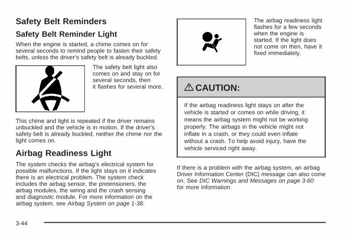
Safety Belt RemindersSafety Belt Reminder LightWhen the engine is started, a chime comes on forseveral seconds to remind people to fasten their safetybelts, unless the driver’s safety belt is already buckled.
The safety belt light alsocomes on and stay on forseveral seconds, thenit flashes for several more.
This chime and light is repeated if the driver remainsunbuckled and the vehicle is in motion. If the driver’ssafety belt is already buckled, neither the chime nor thelight comes on.
Airbag Readiness LightThe system checks the airbag’s electrical system forpossible malfunctions. If the light stays on it indicatesthere is an electrical problem. The system checkincludes the airbag sensor, the pretensioners, theairbag modules, the wiring and the crash sensingand diagnostic module. For more information on theairbag system, see Airbag System on page 1-38.
The airbag readiness lightflashes for a few secondswhen the engine isstarted. If the light doesnot come on then, have itfixed immediately.
{CAUTION:
If the airbag readiness light stays on after thevehicle is started or comes on while driving, itmeans the airbag system might not be workingproperly. The airbags in the vehicle might notinflate in a crash, or they could even inflatewithout a crash. To help avoid injury, have thevehicle serviced right away.
If there is a problem with the airbag system, an airbagDriver Information Center (DIC) message can also comeon. See DIC Warnings and Messages on page 3-60for more information.
3-44

Passenger Airbag Status IndicatorThe vehicle has a passenger sensing system.See Passenger Sensing System on page 1-45 forimportant safety information. The rearview mirror hasa passenger airbag status indicator.
When the vehicle is started, the passenger airbag statusindicator will light ON and OFF, or the symbol for onand off, for several seconds as a system check. Then,after several more seconds, the status indicator will
light either ON or OFF, or either the on or off symbol tolet you know the status of the right front passengerfrontal and seat-mounted side impact airbags.
If the word ON or the on symbol is lit on the passengerairbag status indicator, it means that the right frontpassenger frontal airbag and seat-mounted side impactairbag are enabled (may inflate).
If the word OFF or the off symbol is lit on the passengerairbag status indicator, it means that the passengersensing system has turned off the right front passengerfrontal airbag and seat-mounted side impact airbag.
If, after several seconds, both status indicator lightsremain on, or if there are no lights at all, there may be aproblem with the lights or the passenger sensingsystem. See your dealer/retailer for service.
{CAUTION:
If the airbag readiness light ever comes on andstays on, it means that something may be wrongwith the airbag system. To help avoid injury toyourself or others, have the vehicle serviced rightaway. See Airbag Readiness Light on page 3-44for more information, including important safetyinformation.
United States
Canada
3-45

Charging System LightThis light comes on brieflywhen the ignition key isturned to START, butthe engine is not running,as a check to show itis working.
If it does not, have the vehicle serviced by yourdealer/retailer.
The light should go out once the engine starts. If it stayson, or comes on while driving, there could be a problemwith the charging system. A charging system messagein the Driver Information Center (DIC) can also appear.See DIC Warnings and Messages on page 3-60 for moreinformation. This light could indicate that there areproblems with a generator drive belt, or that there is anelectrical problem. Have it checked right away. If thevehicle must be driven a short distance with the lighton, turn off accessories, such as the radio and airconditioner.
Voltmeter GageWhen the vehicle is inaccessory mode, thevoltmeter shows thevoltage output of thebattery. When the engineis running, it showsthe voltage output of thecharging system.
The reading will change as the rate of charge changes(with engine speed, for example), but if the voltmeterreads at 9 volts or below, the instrument panel clusterand other systems may shut down. The DriverInformation Center (DIC) will read LOW VOLTAGEwhen the vehicle is at 10 volts or below. Have it checkedright away. Driving with the voltmeter reading at10 volts or below could drain the battery and disablethe vehicle.
3-46

Brake System Warning LightThe vehicle’s hydraulic brake system is divided intotwo parts. If one part is not working, the other part canstill work and stop the vehicle. For good braking,though, both parts need to be working well.
This light should come on when the engine is started.If it does not come on then, have it fixed so it willbe ready to warn if there is a problem.
If this warning light stays on after the engine is started,the parking brake may still be set or there could bea brake problem. Refer to Parking Brake on page 2-32to see if it is set. If the parking brake is not set, havethe brake system inspected right away.
If the light comes on while driving and a LOW BRAKEFLUID message is showing on the DIC, pull off the roadand stop carefully. The pedal may be harder to push.Or, the pedal may go closer to the floor and it may takelonger to stop. If the light is still on, have the vehicletowed for service. See Towing Your Vehicle onpage 5-26.
{CAUTION:
The brake system might not be working properly ifthe brake system warning light is on. Driving withthe brake system warning light on can lead to acrash. If the light is still on after the vehicle hasbeen pulled off the road and carefully stopped,have the vehicle towed for service.
United States Canada
3-47

Antilock Brake System (ABS)Warning Light
For vehicles with theAntilock Brake System(ABS), this light comes onbriefly when the engineis started.
If it does not, have the vehicle serviced by yourdealer/retailer. If the system is working normally theindicator light then goes off.
If the ABS light stays on, turn the ignition off. If the lightcomes on while driving, stop as soon as it is safelypossible and turn the ignition off. Then start the engineagain to reset the system. If the ABS light stays on,or comes on again while driving, the vehicle needsservice. If the regular brake system warning light is noton, the vehicle still has brakes, but not antilock brakes.If the regular brake system warning light is also on,the vehicle does not have antilock brakes and there is aproblem with the regular brakes. See Brake SystemWarning Light on page 3-47.
For vehicles with a Driver Information Center (DIC),see DIC Warnings and Messages on page 3-60 for allbrake related DIC messages.
StabiliTrak®/Traction ControlSystem (TCS) Warning Light
The Traction ControlSystem (TCS)/StabiliTraksystem warning lightcomes on briefly as theengine is started.
If it does not, have the vehicle serviced by yourdealer/retailer. If the system is working normally theindicator lights go off.
If the light stays on, or comes on while driving andthe DIC shows a SERVICE TRACTION SYS ora SERVICE STABILITRAK message, there is aproblem with the Traction Control System (TCS)or the StabiliTrak® system and the vehicle needsservice.
3-48

When the Traction Control system and/or StabiliTrak®
system are turned off, the light comes on and achime sounds. The DIC displays either TRACTIONSYSTEM OFF or TRAC/STABILITRAK OFF message.
When this light is on, the TCS system does not limitwheel spin and/or the StabiliTrak® system doesnot assist with vehicle control.
When the Traction Control System and/or StabiliTrak®
system are turned on, the light turns off and a chimesounds. The DIC displays either a TRACTION SYSTEMON or TRAC/STABILITRAK ON message.
See Traction Control System (TCS) on page 5-8,StabiliTrak® System on page 5-6 and DIC Warningsand Messages on page 3-60 for more information.
Engine Coolant Temperature Gage
This gage shows the engine coolant temperature.
As the pointer nears 260°F (125°C), your engine coolanttemperature is high. A message may display on theDriver Information Center (DIC) depending on how highthe temperature is. See DIC Warnings and Messageson page 3-60 for more information.
See Engine Overheating on page 6-27 for moreinformation.
United States Canada
3-49

Tire Pressure LightFor vehicles with the tirepressure light, it comes onbriefly when the engineis started. If it does not,have the vehicle servicedby your dealer/retailer.If the system is workingnormally the indicator lightthen goes off.
This light also comes on when one or more of the tiresis significantly underinflated.
A tire pressure message in the Driver InformationCenter (DIC) can accompany the light. See DICWarnings and Messages on page 3-60 for moreinformation.
Stop and check the tires as soon as it is safe to do so.If underinflated, inflate the tire to the proper pressure.See Tires on page 6-46 for more information.
If a problem is detected with the Tire Pressure MonitorSystem, this light flashes for approximately 60 secondsand then stays on for the remainder of the ignitioncycle. See Tire Pressure Monitor System on page 6-55for more information.
Malfunction Indicator Lamp
Check Engine LightA computer system called OBD II (On-BoardDiagnostics-Second Generation) monitors operation ofthe fuel, ignition, and emission control systems. It makessure that emissions are at acceptable levels for thelife of the vehicle, helping to produce a cleanerenvironment.
This comes on brieflywhile starting the engine.If it does not come on,have the vehicle servicedby your dealer/retailer.
If the check engine light comes on and stays on, whilethe engine is running, this indicates that there is anOBD II problem and service is required.
3-50

Malfunctions often are indicated by the system beforeany problem is apparent. Being aware of the lightcan prevent more serious damage to the vehicle.This system assists the service technician in correctlydiagnosing any malfunction.
Notice: If the vehicle is continually driven with thislight on, after a while, the emission controlsmight not work as well, the vehicle’s fuel economymight not be as good, and the engine might notrun as smoothly. This could lead to costly repairsthat might not be covered by the vehicle warranty.
Notice: Modifications made to the engine,transmission, exhaust, intake, or fuel systemof the vehicle or the replacement of the originaltires with other than those of the same TirePerformance Criteria (TPC) can affect the vehicle’semission controls and can cause this light to comeon. Modifications to these systems could lead tocostly repairs not covered by the vehicle warranty.This could also result in a failure to pass a requiredEmission Inspection/Maintenance test. SeeAccessories and Modifications on page 6-3.
This light comes on during a malfunction in one oftwo ways:
Light Flashing: A misfire condition has been detected.A misfire increases vehicle emissions and coulddamage the emission control system on the vehicle.Diagnosis and service might be required.
The following can prevent more serious damage tothe vehicle:
• Reduce vehicle speed.
• Avoid hard accelerations.
• Avoid steep uphill grades.
If the light continues to flash, when it is safe to do so,stop the vehicle. Find a safe place to park the vehicle.Turn the key off, wait at least 10 seconds, and restartthe engine. If the light is still flashing, follow the previoussteps and see your dealer/retailer for service as soonas possible.
3-51

Light On Steady: An emission control systemmalfunction has been detected on the vehicle.Diagnosis and service might be required.
An emission system malfunction might be corrected bydoing the following:
• Make sure the fuel cap is fully installed. See Fillingthe Tank on page 6-8. The diagnostic system candetermine if the fuel cap has been left off orimproperly installed. A loose or missing fuel capallows fuel to evaporate into the atmosphere.A few driving trips with the cap properly installedshould turn the light off.
• If the vehicle has been driven through a deeppuddle of water, the vehicle’s electrical systemmight be wet. The condition is usually correctedwhen the electrical system dries out. A few drivingtrips should turn the light off.
• Make sure to fuel the vehicle with quality fuel.Poor fuel quality causes the engine not to runas efficiently as designed and may cause:stalling after start-up, stalling when the vehicleis changed into gear, misfiring, hesitation onacceleration, or stumbling on acceleration.These conditions might go away once the engine iswarmed up.
If one or more of these conditions occurs, changethe fuel brand used. It will require at least onefull tank of the proper fuel to turn the light off.See Gasoline Octane on page 6-5.
If none of the above have made the light turn off, yourdealer/retailer can check the vehicle. The dealer/retailerhas the proper test equipment and diagnostic tools tofix any mechanical or electrical problems that might havedeveloped.
3-52

Emissions Inspection andMaintenance ProgramsSome state/provincial and local governments have ormight begin programs to inspect the emission controlequipment on the vehicle. Failure to pass this inspectioncould prevent getting a vehicle registration.
Here are some things to know to help the vehicle passan inspection:
• The vehicle will not pass this inspection if the checkengine light is on with the engine running.
To perform a check engine light bulb check with thekeyless ignition, make sure the transmitter fob is inthe passenger compartment. See Ignition Positionson page 2-24. Press the bottom of the Acc. button onthe instrument panel and hold the button down forfive seconds. The instrument panel, including thecheck engine light, will light up and the ignition will beon, but the engine will not start — press the bottomof the Acc. button only briefly, less than five seconds,the accessory power mode will be turned on, but notthe ignition. After the bulb check, press and releasethe Acc. button again to turn the ignition off and avoiddraining the vehicle’s battery.
• The vehicle will not pass this inspection if theOBD II (on-board diagnostic) system determinesthat critical emission control systems have notbeen completely diagnosed by the system.The vehicle would be considered not ready forinspection. This can happen if the battery hasrecently been replaced or if the battery has run down.The diagnostic system is designed to evaluate criticalemission control systems during normal driving.This can take several days of routine driving. If thishas been done and the vehicle still does not pass theinspection for lack of OBD II system readiness, yourdealer/retailer can prepare the vehicle for inspection.
3-53

Engine Oil Pressure Gage
The engine oil pressure gage shows the engineoil pressure in psi (pounds per square inch) orkPa (kilopascals) when the engine is running.
Oil pressure should be 20 to 80 psi (140 to 550 kPa).In certain situations such as long, extended idles on hotdays, it could read as low as 6 psi (40 kPa) and stillbe considered normal. It may vary with engine speed,
outside temperature and oil viscosity. The DriverInformation Center (DIC) may display messagesregarding the oil condition. See DIC Warnings andMessages on page 3-60 and Engine Oil on page 6-15.
{CAUTION:
Do not keep driving if the oil pressure is low.The engine can become so hot that it catches fire.Someone could be burned. Check the oil as soonas possible and have the vehicle serviced.
Notice: Lack of proper engine oil maintenance candamage the engine. The repairs would not becovered by the vehicle warranty. Always follow themaintenance schedule in this manual for changingengine oil.
United States Canada
3-54

Security LightFor information regardingthis light and the vehicle’ssecurity system, seeTheft-Deterrent Systemon page 2-20.
Fog Lamp LightThe fog lamp light comeson when the fog lamps arein use.
The light goes out when the fog lamps are turned off.See Fog Lamps on page 3-28 for more information.
Lights On ReminderThis light comes onwhenever the headlampsare on.
See Horn on page 3-6 for more information.
Highbeam On LightThis light comes on whenthe high-beam headlampsare in use.
See Headlamp High/Low-Beam Changer on page 3-8for more information.
United States Only
3-55

Fuel GageThe fuel gage indicatesabout how much fuel is leftwhen the ignition isturned on.
An arrow on the fuel gage indicates the side of thevehicle the fuel door is on.
When the needle approaches the low fuel symbol, LOWFUEL will appear on the Driver Information Center (DIC)display. At this time, there is still have a little fuel left,but the vehicle’s fuel tank should be filled soon.
Press RESET to acknowledge a DIC message(s).Pressing RESET will also turn off a DIC message butthe LOW FUEL message will come on again in10 minutes if fuel has not been added to the vehicle.
Here are five things that some owners ask about.All these things are normal and do not indicate thatanything is wrong with the fuel gage.
• At the gas station, the gas pump shuts off beforethe gage reads the full symbol.
• It takes more (or less) fuel to fill up than the gagereads. For example, the gage reads half full, but ittook more (or less) than half of the tank’scapacity to fill it.
• The gage pointer may move while cornering,braking or speeding up.
• The gage may not indicate the tank is empty whenthe ignition is turned off.
• The gage reading may change slightly within thefirst several minutes after starting the vehicle.
3-56

The Driver Information Center (DIC) can be used toshow more detailed fuel information. The DIC,can also display:
• AVERAGE XX.X MPG (Average Miles PerGallon): The fuel economy calculated for thelast 20 gallons (76 L) of fuel used, or since thedisplay was last reset.
• INST XX.X MPG (Instantaneous Miles PerGallon): The fuel economy calculated for currentdriving conditions.
• RANGE XXX MI: The approximate distance thatcan be driven before refueling.
See DIC Operation and Displays on page 3-57 formore information.
Driver Information Center (DIC)This display gives you the status of many of thevehicle’s systems. The DIC is also used to displaydriver personalization features and warning/statusmessages. All messages will appear in the DIC display,located at the bottom of the instrument panel cluster.
DIC Operation and DisplaysThese buttons are locatedto the right of the steeringwheel on the instrumentpanel, near the air outlets.
«4ª(Information): Press to scroll through theavailable features which include the odometer, tripodometers, fuel range, miles per gallon, average speed,timer, tire pressure, and remaining oil life.
3-57
+ (Interior Lamps): Press to turn the interior lampson and off.
OPTIONS: Press to choose personal options that areavailable on the vehicle.
RESET: Press to reset a feature. It is also used toswitch between English and Metric options.
Use the information button to scroll through the followingoptions:
ODOMETER: This feature shows how far the vehiclehas been driven in either miles (mi) or kilometers (km).Use the ENG/METRIC feature to switch betweenEnglish and Metric units.
TRIP A: This feature will record the distance traveledsince the last time it was reset. Press and hold theRESET button to return to zero. If the vehicle is first soldin the United States, the trip odometer will return tozero after 999.9 miles (1 609 km). If the vehicle is firstsold in Canada, the trip odometer will return to zero after1,242 miles (1 999 km).
TRIP B: This feature allows you to record the distancetraveled during a second trip and functions the sameas TRIP A.
RANGE xxx MI: This feature shows about how manymiles (mi) or kilometers (km) you can drive withoutrefilling the fuel tank. Once the range drops below40 miles (64 km) remaining, the display will show LOW.
If the vehicle has been idling for a long time, therange displayed on the DIC could be abnormally low.The vehicle must be driven 5-10 miles (8-16 km) to getan accurate reading.
AVERAGE xx.x MPG (Average Miles Per Gallon):This feature shows the approximate fuel economy thevehicle has averaged since the last time the valuewas reset. To reset the average miles per gallon, pressthe information button to display AVERAGE xx.x MPG,then press and hold the RESET button until AVERAGE00.0 MPG is displayed.
INST xx.x MPG (Instantaneous Miles Per Gallon):This feature shows the instantaneous fuel economywhich varies with your driving conditions, such asacceleration, braking, and the grade of the road beingtraveled. The RESET button does not function inthis mode.
3-58

AVERAGE SPEED: This feature shows the averagespeed the vehicle has traveled since the last timethe value was reset. To reset the value, press theinformation button to display AVERAGE SPEED, thenpress and hold the RESET button until AVERAGESPEED 00.0 is displayed.
ELAPSED TIME: This feature is like a stopwatch, inthat you can clock the time it takes to get from one pointto another.
To operate, press the information button to displayELAPSED TIME. Each of the fields for the hours,minutes, and seconds are two numeric digits.
Once ELAPSED TIME 00:00:00 is displayed, press theRESET button to start the timing feature. Press theRESET button again to stop it. If you will be starting andstopping the vehicle, during a trip for instance, theELAPSED TIME feature will automatically start timingwhere it left off when you last stopped. To reset it, pressand hold the RESET button until the display readsELAPSED TIME 00:00:00. Press the information buttonto exit from the ELAPSED TIME display.
FRONT Lxx Rxx PSI: This feature shows the tirepressure for the front left and right tires.
REAR Lxx Rxx PSI: This feature shows the tirepressure for the rear left and right tires.
OIL LIFE: This feature shows the estimated oil liferemaining. See Oil Life Indicator on page 3-76 for moreinformation. To reset the engine oil life system, seeEngine Oil Life System on page 6-18. This only needsto be reset after you have had the oil changed.
In addition to the engine oil life system monitoring oillife, additional maintenance is recommended in theMaintenance Schedule in this manual. See ScheduledMaintenance on page 7-4 and Engine Oil on page 6-15for more information.
ENG/METRIC (English/Metric): This feature allowsyou to switch the DIC displays between Englishand Metric. Press the RESET button to switch thedisplay between English and Metric. There will be anarrow next to the option that is selected.
3-59

DIC Warnings and MessagesThese messages appear if there is a problem detectedin one of the vehicle’s systems. You must then pressRESET to clear the display screen for further use.However, be sure to take any message that appearson the display screen seriously and remember thatpressing the RESET button will only make the messagedisappear, not the problem.
DIC messages can also be displayed in English,French, German, Italian, Japanese, and Spanish.
ABS (Antilock Brake System) ACTIVEThis message displays when the Antilock BrakeSystem (ABS) is adjusting brake pressure to help avoida braking skid.
Slippery road conditions may exist if this messagedisplays, so adjust your driving accordingly. Themessage may stay on for a few seconds after thesystem stops adjusting brake pressure.
BUCKLE PASSENGERThis message reminds you to buckle the passengersafety belt.
This message displays and a chime sounds whenthe ignition is on, the driver safety belt is buckled,the passenger safety belt is unbuckled with the
passenger airbag enabled, and the vehicle is inmotion. You should have the passenger buckle theirsafety belt.
The reminder will be repeated if the ignition is on, thevehicle is in motion, the driver is buckled and thepassenger is still unbuckled, and the passenger airbagis enabled. If the passenger safety belt is alreadybuckled, this message and chime will not come on.
BUCKLE SEAT BELTThis message reminds you to buckle the driversafety belt.
This message displays and a chime sounds when theignition is on, the driver safety belt is unbuckled, and thevehicle is in motion. You should buckle the safety belt.
If the driver remains unbuckled when the ignition ison and the vehicle is in motion, the reminder willbe repeated. If the driver safety belt is already buckled,this message and chime will not come on.
This message is an additional reminder to the SafetyBelt Reminder Light in the instrument panel cluster.See Safety Belt Reminders on page 3-44 for moreinformation.
3-60

CHANGE OIL NOWThis message displays when the life of the engine oilhas expired. See Scheduled Maintenance on page 7-4.After an oil change, the Oil Life Indicator must bereset. See Oil Life Indicator on page 3-76 and EngineOil Life System on page 6-18.
CHARGE SYSTEM FAULTThis message displays when a problem with thecharging system has been detected. Have the vehicleserviced by your dealer/retailer.
CHECK GAS CAPThis message displays if the fuel cap has not been fullytightened. Check the fuel cap to make sure that it ison properly.
CLEAN RADAR CRUISEIf the vehicle has this feature, this message displayswhen the Adaptive Cruise Control (ACC) systemis disabled because the radar is blocked and cannotdetect vehicles in your path. It may also activate duringheavy rain or due to road spray. To clean the system,see Adaptive Cruise Control on page 3-14.
CLOSE CARGO DIVIDERThis message displays if the cargo divider is not inplace. Open the trunk and make sure the cargo divideris secure and no objects are on the divider. See RearStorage Area on page 2-54 for more information.
COOLANT OVER TEMP (Temperature)This message displays when the engine coolanttemperature is too hot. Stop and allow the vehicle toidle in P (Park) until it cools down and the message isremoved. Do not increase engine speed above anormal idle. If it does not cool down, turn off the engineand have the vehicle serviced by your dealer/retailerbefore driving it again. Severe engine damage can resultfrom an overheated engine. See Engine Overheatingon page 6-27.
CRUISE NOT READYThis message indicates that the Adaptive Cruise Control(ACC) will not activate due to a temporary condition.The vehicle does not require service. If this messagedisplays when you attempt to activate the system,continue driving for several minutes, then try to activatethe system again.
3-61

DRIVER NO. X (1 OR 2)This message displays when the vehicle is started orwhen there is a change of driver. The messageshows which driver is activating the personalizationfeature. It will only stay on for five seconds.
ENGINE HOT, STOP ENGINEThis message displays when the engine has overheated.Stop and turn the engine off immediately to avoidsevere engine damage. See Engine Overheating onpage 6-27. A multiple chime also sounds whenthis message displays.
ENGINE PROTECTION REDUCEENGINE RPMIf this message displays, the control system hasdetermined that continued operation at the existingengine speed may lead to engine overheating. Lowerthe engine speed by upshifting the transmission or driveat a lower speed.
HEADLAMPS SUGGESTEDThis message displays if it is dark enough outside andthe headlamps and Twilight Sentinel® controls areoff. This message informs the driver that turning on the
exterior lamps is recommended. It has become darkenough outside to require the headlamps and/or otherexterior lamps. This message also displays if theoptional Rainsense™ wiping feature is on and theTwilight Sentinel is off.
HIGH TRANS (Transmission) TEMP(Temperature)This message displays when the transmission fluid inthe vehicle is too hot. Stop and allow the vehicle to idleuntil it cools down or until this message is removed.
HIGH VOLTAGEThis message displays when the electrical chargingsystem is overcharging. To avoid being stranded, havethe electrical system checked by your dealer/retailer.You can reduce the charging overload by usingthe accessories. Turn on the lamps and radio, set theclimate control on AUTO and the fan speed on HI,and turn the rear window defogger on. You can monitorbattery voltage on the DIC by pressing the informationbutton. The normal range is 11.5 to 15.5 volts when theengine is running.
3-62

HOT ENGINE–A/C OFFThis message displays when the engine coolantbecomes hotter than the normal operating temperature.You can continue to drive the vehicle. If this messagecontinues to display, have the system repaired byyour dealer/retailer as soon as possible to avoidcompressor damage.
ICE POSSIBLEThis message displays when the outside air temperatureis cold enough to create icy road conditions. Adjust yourdriving accordingly.
LEFT DOOR AJARThis message displays anytime the engine is running,the transmission is not in P (Park), and the driver dooris open or ajar. A chime sounds when the vehicle’sspeed is greater than 3 mph (5 km/h).
LOW BRAKE FLUIDThis message displays if the engine is running to informthe driver that the brake fluid level is low. Have thebrake system serviced by your dealer/retailer as soonas possible. See “Brake Fluid” under Brakes onpage 6-32.
LOW COOLANTThis message displays when there is a low level ofengine coolant. Have the cooling system serviced byyour dealer/retailer as soon as possible. See EngineCoolant on page 6-23.
LOW FUELThis message displays when the fuel supply is lessthan 5 gallons (18.9 L) and the display is turned off.A single chime also sounds when this message isdisplayed.
LOW OIL LEVELFor correct operation of the low oil sensing system,the vehicle should be on a level surface. A false LOWOIL LEVEL message may display if the vehicle is parkedon a grade. The oil level sensing system does notcheck for actual oil level if the engine has been off for ashort period of time, and the oil level is never checkedwhile the engine is running. If the LOW OIL LEVELmessage displays, and the vehicle has been parked onlevel ground with the engine off for at least 30 minutes,the oil level should be checked by observing the oildipstick. Prior to checking the oil level, make sure theengine has been off for a few minutes and the vehicle ison a level surface. Then check the dipstick and addoil if necessary. See Engine Oil on page 6-15.
3-63

LOW OIL PRESSURENotice: If you drive your vehicle while the engineoil pressure is low, severe engine damage mayoccur. If a low oil pressure warning appears on theDriver Information Center (DIC), stop the vehicleas soon as possible. Do not drive the vehicle untilthe cause of the low oil pressure is corrected.See Engine Oil on page 6-15 for more information.
If this message displays while the engine is running,stop the engine and do not operate the vehicle until thecause of low oil pressure is corrected. Severe damageto the engine can result. A multiple chime sounds whenthis message is displayed.
LOW VOLTAGEThis message displays when the electrical systemis charging less than 10 volts or if the battery hasbeen drained. If this message displays immediatelyafter starting, it is possible that the generator can stillrecharge the battery. The battery should recharge whiledriving, but may take a few hours to do so. Considerusing an auxiliary charger to boost the battery afterreturning home or to a final destination. Make sure youfollow the manufacturer’s instructions. If this messagedisplays while driving or after starting the vehicle
and stays on, have it checked immediately by yourdealer/retailer to determine the cause of this problem.To help the generator recharge the battery quickly,you can reduce the load on the electrical systemby turning off the accessories. You can monitor batteryvoltage on the DIC by pressing the INFO button.The normal range is 11.5 to 15.5 volts.
LOW WASHER FLUIDThis message displays when the windshield washerfluid is low. Fill the windshield washer fluid reservoir assoon as possible. See Engine Compartment Overviewon page 6-12 for the location of the windshieldwasher fluid reservoir. Also, see Windshield WasherFluid on page 6-31 for more information.
MAX (Maximum) SPEED XX MPH(XX KM/H)This message displays when a failure in the magneticride control system has occurred. The PowertrainControl Module (PCM) determines the speed to whichthe vehicle is limited. Have the vehicle serviced by yourdealer/retailer if this message appears.
3-64

NO FOB DETECTEDThis message displays if the vehicle does not detect thepresence of a keyless access transmitter when youhave attempted to start the vehicle or a vehicle door hasjust closed. The following conditions may cause thismessage to appear:
• Driver-added equipment plugged into the accessorypower outlet on the center console is causinginterference. Examples of these devices are cellphones and cell phone chargers, two-way radios,power inverters, or similar items. Try movingthe keyless access transmitter away from thesedevices when starting the vehicle. In addition,PDA devices and remote garage and gate openersmay also generate Electromagnetic Interference(EMI) that may interfere with the keyless accesstransmitter. Do not carry the keyless accesstransmitter in the same pocket or bag as thesedevices.
• The vehicle is experiencing ElectromagneticInterference (EMI). Some locations, such asairports, automatic toll booths, and some gasstations, have EMI fields which may interfere withthe keyless access transmitter.
If moving the transmitter to different locationswithin the vehicle does not help, place thetransmitter in the glove box transmitter pocketwith the buttons facing to the right and then pressthe START button.
• The vehicle’s battery voltage is low. The batteryvoltage must be above 10 volts for the keylessaccess transmitter to be detected properly.
3-65
NO FOB, OFF OR RUN?This message displays when a keyless accesstransmitter is not detected inside the vehicle whileyou are trying to turn the ignition off. The vehicle maybe near a strong radio antenna signal causing thekeyless access system to be jammed. The vehicle willremain in ACCESSORY until the vehicle is turned off oris restarted, or five minutes has expired. If you turnthe ignition off and you cannot find the keyless accesstransmitter, you will not be able to restart the vehicle.The keyless access transmitter needs to be inside of thevehicle in order for the vehicle to start. See Startingthe Engine on page 2-26 for more information.
OVER SPEED WARNINGThis message displays when the vehicle speed exceedsa certain limit as required by some export countries.A chime sounds when this message is displayed.
PRESS BRAKE TO STARTThis message displays to inform you that the brakepedal must be applied to start the vehicle. Make sureyou are pressing the brake pedal all the way down.
REDUCED ENGINE POWERThis message displays when the vehicle is reducingengine power because the transmission is being placedin gear under conditions that may cause damage to thevehicle’s engine, transmission, or ability to accelerate.Reduced engine power can affect the vehicle’s ability toaccelerate. If this message is on, but there is no reductionin performance, proceed to your destination. Theperformance may be reduced the next time the vehicle isdriven. The vehicle may be driven at a reduced speedwhile this message is on, but acceleration and speed maybe reduced. Anytime this message stays on, the vehicleshould be taken to your dealer/retailer for service as soonas possible.
RIGHT DOOR AJARThis message displays anytime the engine is running,the transmission is not in P (Park), and the passengerdoor is open or ajar. A chime sounds if the vehicle’sspeed is greater than 3 mph (5 km/h).
SERVICE A/CThis message displays when the electronic sensors thatcontrol the air conditioning and heating systems areno longer working. Have the climate control systemserviced by your dealer/retailer if you notice a drop inheating and air conditioning efficiency.
3-66

SERVICE ABS (Antilock Brake System)If this message displays when you are driving, stopas soon as possible and turn the ignition off. Then startthe engine again to reset the system. If the messagestays on, or comes back on again while you are driving,the vehicle is in need of service. See your dealer/retailer.
If the SERVICE ABS message is being displayed, theTraction Control System (TCS) and StabiliTrak® Systemwill also be disabled. The Driver Information Centerwill scroll three messages: SERVICE ABS, SERVICETRACTION SYS, and SERVICE STABILITRAK, and theantilock brake system and traction control warninglights on the instrument panel cluster will be illuminated.See Antilock Brake System (ABS) Warning Light onpage 3-48 and StabiliTrak®/Traction Control System(TCS) Warning Light on page 3-48. The driver canacknowledge these messages by pressing the RESETbutton three times. When the service message isdisplayed, the computer controlled systems will notassist the driver and you should have the systemrepaired by your dealer/retailer as soon as possible.Adjust your driving accordingly.
SERVICE AFS (Adaptive ForwardLighting System) LAMPSThis message displays when the Adaptive ForwardLighting System (AFS) is disabled and needs service.See your dealer/retailer. See Adaptive Forward LightingSystem on page 3-28 for more information.
SERVICE ELECT (Electrical) SYSTEMThis message displays if an electrical problem hasoccurred within the Powertrain Control Module (PCM).Have the vehicle serviced by your dealer/retailer.
SERVICE FUEL SYSTEMThis message displays when the Powertrain ControlModule (PCM) has detected a problem within the fuelsystem. Have the vehicle serviced by your dealer/retailer.This message will also be displayed when the cluster isnot getting fuel information from the PCM.
SERVICE RADAR CRUISEIf the vehicle has this feature, this message displayswhen the Adaptive Cruise Control (ACC) systemis disabled and needs service. See your dealer/retailer.
3-67

SERVICE RIDE CONTROLThis message displays when there is a problem withthe Magnetic Ride Control System. Have the vehicleserviced by your dealer/retailer.
SERVICE TRACTION SYS (System)This message displays when there is a problem withthe Traction Control System (TCS). Have the vehicleserviced by your dealer/retailer.
SERVICE STABILITRAKIf this message displays, it means there may be aproblem with the stability enhancement system. If yousee this message, try to reset the system. Stop, turn offthe engine, then start the engine again. If this messagestill comes on, it means there is a problem. You shouldsee your dealer/retailer for service. Reduce yourspeed and drive accordingly. A single chime alsosounds when this message is displayed.
SERVICE TRANSMISSIONThis message displays when there is a problem withthe transmission. Have the vehicle serviced byyour dealer/retailer.
SERVICE VEHICLE SOONThis message displays when a non-emissions relatedpowertrain malfunction occurs. Have the vehicleserviced by your dealer/retailer as soon as possible.
SHIFT TO PARKThis message displays if the vehicle is not in P (Park)when the engine is being turned off. The vehicle will bein accessory mode. Once the shift lever is moved toP (Park), the vehicle will turn off.
STABILITRAK ACTIVEYou may see this message on the DIC. It means thatan advanced, computer-controlled system has come onto help the vehicle continue to go in the direction inwhich you are steering. This stability enhancementsystem activates when the computer senses that thevehicle is just starting to spin, as it might if you hita patch of ice or other slippery spot on the road.When the system is on, you may hear a noise orfeel a vibration in the brake pedal. This is normal.
When this message is on, continue to steer in thedirection you want to go. The system is designed to helpyou in bad weather or other difficult driving situations bymaking the most of whatever road conditions will permit.If this message comes on, you will know that somethinghas caused the vehicle to start to spin, so considerslowing down. A single chime also sounds when thismessage is displayed.
3-68

STABILITRAK READYIf this message displays and a chime sounds, thesystem has completed the functional check of theStabiliTrak® System.
SVC (Service) TIRE MONITORThis message displays if a part on the Tire PressureMonitor System (TPMS) is not working properly. The tirepressure light also flashes and then remains on duringthe same ignition cycle. See Tire Pressure Light onpage 3-50. Several conditions may cause this messageto appear. See Tire Pressure Monitor Operation onpage 6-57 for more information. If the warning comes onand stays on, there may be a problem with the TPMS.See your dealer/retailer.
TOO COLD TO MOVE TOPThis message displays when the retractable hardtopbutton is pressed and the hardtop pump motortemperature is below −4°F (−20°C). Wait for the hardtoppump motor to warm up before using the retractablehardtop.
TOP INOP (Inoperative) – VALET ONThis message displays when the retractable hardtopbutton is pressed and the valet switch is on. Turn off thevalet switch before using the retractable hardtop.
TOP INOP (Inoperative) OUT OF PARKThis message displays if the retractable hardtopbutton is pressed while the vehicle is not in P (Park).
TOP MOTOR OVER TEMP (Temperature)This message displays when the retractable hardtopbutton is pressed and the hardtop pump motortemperature is over 221°F (105°C). Wait for the hardtoppump motor to cool down before using the retractablehardtop.
TOP NOT SECUREThis message displays when the retractable hardtopbutton is released before the top open or close operationis complete. Press and hold the retractable hardtopbutton to fully open or close the top.
TRAC (Traction) SYSTEM ACTIVEThis message displays when the Traction ControlSystem (TCS) is limiting wheel spin. Slippery roadconditions may exist if this message is displayed,so adjust your driving accordingly. This message stayson for a few seconds after the TCS stops limitedwheel spin.
3-69

TRAC (Traction)/STABILITRAK OFFThis message displays when both the Traction ControlSystem (TCS) and the StabiliTrak® System are off.This message will remain until the systems are turnedon again.
TRAC (Traction)/STABILITRAK ONThis message displays when both the Traction ControlSystem (TCS) and the StabiliTrak® System are on.
TRACTION SYSTEM OFFThis message displays when the Traction ControlSystem (TCS) is off, but the StabiliTrak® Systemremains on.
TRACTION SYSTEM ONThis message displays when the Traction ControlSystem (TCS) is on.
TRUNK AJARThis message displays when the trunk is open while thevehicle is running and is not in P (Park).
Other MessagesHere are more messages that you can receive on theDriver Information Center (DIC). To acknowledge amessage and read another message that may havecome on at the same time, press the RESET button.
• ACCESSORY MODE ON
See Ignition Positions on page 2-24.
• CHANGE OIL SOON
See Engine Oil on page 6-15 and Engine Oil LifeSystem on page 6-18.
• FOB BATTERY LOW
See “Battery Replacement” under Keyless AccessSystem Operation on page 2-5.
• HIGH TIRE PRESS LF
See Inflation - Tire Pressure on page 6-54.
• HIGH TIRE PRESS RF
See Inflation - Tire Pressure on page 6-54.
• HIGH TIRE PRESS LR
See Inflation - Tire Pressure on page 6-54.
• HIGH TIRE PRESS RR
See Inflation - Tire Pressure on page 6-54.
3-70
• INTRUSION SENSOR OFF
See Theft-Deterrent System on page 2-20.
• INTRUSION SENSOR ON
See Theft-Deterrent System on page 2-20.
• KNOWN FOB
See “Matching Transmitter(s) to Your Vehicle”under Keyless Access System Operation onpage 2-5.
• LEFT FRONT TIRE FLAT MAX SPD 55,REDUCED HNDLGSee Inflation - Tire Pressure on page 6-54.
• LEFT REAR TIRE FLAT MAX SPD 55,REDUCED HNDLGSee Inflation - Tire Pressure on page 6-54.
• LOW TIRE PRESS LF
See Inflation - Tire Pressure on page 6-54.
• LOW TIRE PRESS RF
See Inflation - Tire Pressure on page 6-54.
• LOW TIRE PRESS LR
See Inflation - Tire Pressure on page 6-54.
• LOW TIRE PRESS RR
See Inflation - Tire Pressure on page 6-54.
• MAX # FOBS LEARNED
See “Matching Transmitter(s) to Your Vehicle”under Keyless Access System Operation onpage 2-5.
• OFF-ACC TO LEARN
See “Matching Transmitter(s) to Your Vehicle”under Keyless Access System Operation onpage 2-5.
• READY FOR FOB #X
See “Matching Transmitter(s) to Your Vehicle”under Keyless Access System Operation onpage 2-5.
• RIGHT FRT TIRE FLAT MAX SPD 55,REDUCED HNDLGSee Inflation - Tire Pressure on page 6-54.
• RIGHT REAR TIRE FLAT MAX SPD 55,REDUCED HNDLGSee Inflation - Tire Pressure on page 6-54.
• WAIT XX MINUTES
See “Matching Transmitter(s) to Your Vehicle”under Keyless Access System Operation onpage 2-5.
3-71

DIC Vehicle PersonalizationThe vehicle has personalization capabilities that allowyou to program certain features to a preferred setting forup to two drivers. The back of the keyless accesstransmitters are labelled 1 or 2.
The current driver preferences are recalled when one ofthe following occurs:• The lock or unlock button on the keyless access
transmitter, programmed as 1 or 2, is pressed.• The appropriate memory button, 1 or 2, located on
the driver seat is pressed. See Memory Seat,Mirrors and Steering Wheel on page 1-3 for moreinformation.
• A valid keyless access transmitter is detected uponopening the driver door.
If more than one valid keyless access transmitter isdetected upon opening the driver door, the driverpreferences for the lowest driver number will be recalled.
If a keyless access transmitter is programmed as#3 or #4, the personalization system will not recognizethe transmitter. The Driver Information Center (DIC)will not display a current driver number and the featuresthat are normally programmed through the DIC willbe set to the default states. Also, if the OPTIONS buttonis pressed, the DIC does not display the menus usedto set personalizations, but instead displays OPTIONSUNAVAILABLE for a few seconds.
Feature ProgrammingTo change feature preferences, make sure the vehicleis running and in P (Park). To avoid excessive drainon the battery, it is recommended that the headlampsare turned off. Press the OPTIONS button and the DriverInformation Center (DIC) will display the current driverfor a few seconds, then display the first personalizationmenu item. You can now use the OPTIONS buttonto change the setting of the displayed feature. Press thetop or bottom of the information button to scroll up ordown the list of features. When you get to a feature youwant to change, press the OPTIONS button again.When you are finished, press the RESET button to exitthe personalization menu. If no button is pressed within45 seconds, the DIC will exit the personalization menu.
The following are DIC options that will be available in thepersonalization menu.
Auto RecallThis feature allows the steering column, outside mirrorsand the driver seat to automatically move to thecurrent driver’s set position when the engine starts.The DIC will display AUTO RECALL OFF or AUTORECALL ON. Press the OPTIONS button to changethe setting.
3-72

Auto Exit RecallThis feature allows the steering column and driver seatto automatically move to the current driver’s exitposition when one of the following occurs:
• The vehicle is turned off or in RAP or accessorymode and the driver’s door is opened.
• The vehicle is turned off or in RAP and the unlockbutton on the keyless access transmitter ispressed.
The DIC will display AUTO EXIT RECALL OFF orAUTO EXIT RECALL ON. Press the OPTIONS buttonto change the setting.
Approach LightsThis feature activates the parking lamps, front fog lampsand back-up lamps during low light periods when theunlock button on the keyless access transmitter ispressed, both doors are closed and the vehicle is off orin RAP. The lamps remain on for 20 seconds or untila door is opened, the lock button on the keyless accesstransmitter is pressed or the vehicle is no longer offor in RAP.
The DIC will display APPROACH LIGHTS OFF orAPPROACH LIGHTS ON. Press the OPTIONS buttonto change the setting.
Exit LightsThis feature activates the parking lamps and front foglamps for 15, 30 or 90 seconds. This will occur when thevehicle is off or in RAP and the headlamps are ondue to the automatic headlamp system. The parkinglamps and front fog lamps will remain on until the driverselected time period expires, the exterior lamp controlis activated or the vehicle is no longer off or in RAP.
The DIC will display EXIT LIGHTS OFF, EXITLIGHTS - 15 SEC, EXIT LIGHTS - 30 SEC, or EXITLIGHTS - 90 SEC. Press the OPTIONS button tochange the setting.
Flash at UnlockThis feature activates the front and rear turn signals fortwo short flashes when the unlock or trunk button onthe keyless access transmitter is pressed. This will onlyoccur when the vehicle is off.
The DIC will display NO FLASH AT UNLOCK orFLASH AT UNLOCK. Press the OPTIONS button tochange the setting.
3-73

Flash at LockThis feature activates the front and rear turn signals forone long flash when the lock button on the keylessaccess transmitter is pressed. This will only occur whenthe vehicle is off. If the lock button is pressed againwithin five seconds, the horn will sound regardless ofwhich setting you have selected.
The DIC will display NO FLASH AT LOCK orFLASH AT LOCK. Press the OPTIONS button tochange the setting.
FOB ReminderThis feature sounds the horn three times when thedriver door is closed and there is a keyless accesstransmitter inside the interior of the vehicle. This will onlyoccur when the vehicle is off.
The DIC will display FOB REMINDER OFF orFOB REMINDER HORN. Press the OPTIONS buttonto change the setting.
Passive LockingThis feature allows you to select whether the doorsautomatically lock during normal vehicle exit. When theignition is turned off and all doors become closed,the vehicle will determine how many keyless accesstransmitters remain in the vehicle interior. If at least
one keyless access transmitter has been removed fromthe interior of the vehicle, the doors will lock aftereight seconds.
For example, if there are two keyless accesstransmitters in the vehicle and one is removed, theother will be locked in. The keyless access transmitterlocked in the vehicle can still be used to start the vehicleor unlock the doors, if needed. A person approachingthe outside of the locked vehicle without an authorizedkeyless access transmitter, however, will not be ableto open the door, even with a transmitter in the vehicle.
You may temporarily disable the passive door lockingfeature by pressing the door unlock switch forthree seconds on an open door. Passive door locking willthen remain disabled until a door lock switch is pressed oruntil the power mode transitions from the off power mode.
You can select to not have the horn sound when thepassive lock occurs. If you choose this setting, the doorswill automatically lock eight seconds after you turn theignition off, remove a keyless access transmitterfrom the interior of the vehicle, and close both doors.
You can also select to have the horn sound once whenthe passive lock occurs. If you choose this setting,the doors will automatically lock and the horn will chirpeight seconds after you turn the ignition off, removea keyless access transmitter from the interior ofthe vehicle, and close both doors.
3-74

If you are parking in a quiet area and do not want thehorn to sound when the doors lock, press the lock buttonon the keyless access transmitter immediately afterremoving it from the interior and closing the doors.This will lock the doors and cancel the passive lockingfor this ignition cycle.
The DIC will display PASSIVE LOCKING OFF, SILENTPASSIVE LOCK, or HORN AT PASSIVE LOCK.Press the OPTIONS button to change the setting.
Passive UnlockingThis feature allows you to select which doors willautomatically unlock when you approach and openthe driver door with the keyless access transmitter.You can choose to have the driver door unlock orboth doors unlock. See Door Locks on page 2-10 formore information.
The DIC will display PASSIVE UNLK DRIVER orPASSIVE UNLK BOTH. Press the OPTIONS button tochange this setting.
Auto UnlockThis feature automatically unlocks either the driver dooror both doors, depending on the setting, when theshift lever is moved to P (Park).
The DIC will display AUTO UNLOCK OFF, AUTOUNLOCK DRIVER, or AUTO UNLOCK BOTH.Press the OPTIONS button to change the setting.
Park AssistThis feature tilts the passenger side mirror downwardwhen the shift lever is moved to R (Reverse). This canhelp you to see the curb while backing up. If youadjust the mirror while in R (Reverse), the new positionwill be saved as the park assist position.
The DIC will display PARK ASSIST OFF orPARK ASSIST ON.
LanguageThis feature allows you to select the language theDIC and Head-Up Display (HUD), uses to displaymessages.
The DIC will display ENGLISH, FRENCH, GERMAN,ITALIAN, JAPANESE, or SPANISH. Press theOPTIONS button to change the setting.
If you become stuck in a language that you do notunderstand, hold the OPTIONS and RESET buttonsfor five seconds. The DIC will scroll through allavailable languages for as long as the buttons are held.Each language option will display in its own language.For example, English will be displayed as ENGLISH,Spanish as ESPANOL, etc. When the desired languageis available, release the buttons and the DIC will setto this language.
3-75

Trip Computer
Oil Life IndicatorThis feature lets you know when to change the engineoil. It is based on the engine oil temperatures andyour driving patterns.
To see the display, press the information button severaltimes until OIL LIFE appears. If you see 99% OIL LIFE,99 percent of the current oil life remains.
The DIC may display a CHANGE OIL NOW message.If you see CHANGE OIL NOW, it means the oil lifeis gone. For more information, see ScheduledMaintenance on page 7-4 and Engine Oil on page 6-15.
When the oil is changed, you will need to reset thesystem. See Engine Oil Life System on page 6-18.Always keep a written record of the mileage and datewhen you changed your oil.
Audio System(s)Read the following pages to become familiar with theaudio system’s features.
{CAUTION:
Taking your eyes off the road for extended periodscould cause a crash resulting in injury or death toyou or others. Do not give extended attention toentertainment tasks while driving.
This system provides access to many audio and nonaudio listings.
To minimize taking your eyes off the road while driving,do the following while the vehicle is parked:
• Become familiar with the operation and controls ofthe audio system.
• Set up the tone, speaker adjustments, and presetradio stations.
For more information, see Defensive Driving onpage 5-2.
3-76

Notice: Contact your dealer/retailer before addingany equipment.
Adding audio or communication equipment couldinterfere with the operation of the vehicle’s engine,radio, or other systems, and could damage them.Follow federal rules covering mobile radio andtelephone equipment.
The vehicle has Retained Accessory Power (RAP).With RAP, the audio system can be played even afterthe ignition is turned off. See Retained AccessoryPower (RAP) on page 2-25 for more information.
Bluetooth®
Vehicles with a Bluetooth system can use a Bluetoothcapable cell phone with a Hands Free Profile to make andreceive phone calls. The system can be used while thekey is in ON/RUN or ACC/ACCESSORY position. Therange of the Bluetooth system can be up to 30 ft. (9.1 m).Not all phones support all functions, and not all phonesare guaranteed to work with the in-vehicle Bluetoothsystem. See gm.com/bluetooth for more information oncompatible phones.
Voice RecognitionThe Bluetooth system uses voice recognition to interpretvoice commands to dial phone numbers and name tags.
Noise: Keep interior noise levels to a minimum.The system may not recognize voice commands if thereis too much background noise.
When to Speak: A short tone sounds after the systemresponds indicating when it is waiting for a voicecommand. Wait until the tone and then speak.
How to Speak: Speak clearly in a calm andnatural voice.
Audio SystemWhen using the in-vehicle Bluetooth system, soundcomes through the vehicle’s front audio system speakersand over-rides the audio system. Use the audiosystem volume knob, during a call, to change thevolume level. The adjusted volume level remains inmemory for later calls. To prevent missed calls, aminimum volume level is used if the volume is turneddown too low.
3-77

Bluetooth ControlsUse the buttons located on the steering wheel to operatethe in-vehicle Bluetooth system. See Audio SteeringWheel Controls on page 3-88 for more information.
bg (Push To Talk): Press to answer incoming calls,to confirm system information, and to start speechrecognition.
cª(Phone On Hook): Press to end a call, reject acall, or to cancel an operation.
PairingA Bluetooth enabled cell phone must be paired to thein-vehicle Bluetooth system first and then connected tothe vehicle before it can be used. See the cell phonemanufacturers user guide for Bluetooth functions beforepairing the cell phone. If a Bluetooth phone is notconnected, calls will be made using OnStar® Hands-FreeCalling, if available. Refer to the OnStar owner’s guidefor more information.
Pairing Information:
• Up to five cell phones can be paired to the in-vehicleBluetooth system.
• The pairing process is disabled when the vehicleis moving.
• The in-vehicle Bluetooth system automatically linkswith the first available paired cell phone in theorder the phone was paired.
• Only one paired cell phone can be connected to thein-vehicle Bluetooth system at a time.
• Pairing should only need to be completed once,unless changes to the pairing information havebeen made or the phone is deleted.
To link to a different paired phone, see Linking to aDifferent Phone later in this section.
3-78

Pairing a Phone1. Press and hold b g for two seconds. The system
responds with “Ready” followed by a tone.
2. Say “Bluetooth”. The system responds with“Bluetooth ready” followed by a tone.
3. Say “Pair”. The system responds with instructionsand a four digit PIN number. The PIN number willbe used in Step 4.
4. Start the Pairing process on the cell phone that willbe paired to the vehicle. Reference the cell phonemanufacturers user guide for information onthis process.Locate the device named “General Motors” in the liston the cellular phone and follow the instructions onthe cell phone to enter the four digit PIN number thatwas provided in Step 3.
5. The system prompts for a name for the phone. Use aname that best describes the phone. This name willbe used to indicate which phone is connected.The system then confirms the name provided.
6. The system responds with “<Phone name> hasbeen successfully paired” after the pairing processis complete.
7. Repeat Steps 1 through 7 for additional phones tobe paired.
Listing All Paired and Connected Phones1. Press and hold bg for two seconds. The system
responds with “Ready” followed by a tone.
2. Say “Bluetooth”. The system responds with“Bluetooth ready” followed by a tone.
3. Say “List”. The system lists all the paired Bluetoothdevices. If a phone is connected to the vehicle, thesystem will say “Is connected” after the connectedphone.
Deleting a Paired Phone1. Press and hold b g for two seconds. The system
responds with “Ready” followed by a tone.
2. Say “Bluetooth”. The system responds with“Bluetooth ready” followed by a tone.
3. Say “Delete”. The system asks which phone todelete followed by a tone.
4. Say the name of the phone to be deleted. If thephone name is unknown, use the “List” commandfor a list of all paired phones. The system respondswith “Would you like to delete <phone name>?Yes or No” followed by a tone
5. Say “Yes” to delete the phone. The systemresponds with “OK, deleting <phone name>”.
3-79

Linking to a Different Phone1. Press and hold b g for two seconds. The system
responds with “Ready” followed by a tone.
2. Say “Bluetooth”. The system responds with“Bluetooth ready” followed by a tone.
3. Say “Change phone”. The system responds with“Please wait while I search for other phones”.
• If another phone is found, the response will be“<Phone name> is now connected”.
• If another phone is not found, the original phoneremains connected.
Storing Name TagsThe system can store up to thirty phone numbers asname tags that are shared between the Bluetooth andOnStar systems.
The system uses the following commands to store andretrieve phone numbers:
• Store
• Digit Store
• Directory
Using the Store CommandThe store command allows a phone number to bestored without entering the digits individually.
1. Press and hold b g for two seconds. The systemresponds with “Ready” followed by a tone.
2. Say “Store”. The system responds with “Store,number please” followed by a tone.
3. Say the complete phone number to be stored atonce with no pauses.
• If the system recognizes the number it respondswith “OK, Storing” and repeats the phone number.
• If the system is unsure it recognizes the phonenumber, it responds with “Store” and repeats thenumber followed by “Please say yes or no”. If thenumber is correct, say “Yes”. If the number is notcorrect, say “No”. The system will ask for thenumber to be re-entered.
4. After the system stores the phone number,it responds with “Please say the name tag”followed by a tone.
3-80

5. Say a name tag for the phone number. The nametag is recorded and the system responds with“About to store <name tag>. Does that sound OK?”.
• If the name tag does not sound correct, say“No” and repeat Step 5.
• If the name tag sounds correct, say “Yes” andthe name tag is stored. After the number isstored the system returns to the main menu.
Using the Digit Store CommandThe digit store command allows a phone number to bestored by entering the digits individually.
1. Press and hold b g for two seconds. The systemresponds with “Ready” followed by a tone.
2. Say “Digit Store”. The system responds with “Pleasesay the first digit to store” followed by a tone.
3. Say the first digit to be stored. The system willrepeat back the digit it heard followed by a tone.Continue entering digits until the number to bestored is complete.
• If an unwanted number is recognized by thesystem, say “Clear” at any time to clear the lastnumber.
• To hear all of the numbers recognized by thesystem, say “Verify” at any time and the systemwill repeat them.
4. After the complete number has been entered, say“Store”. The system responds with “Please say thename tag” followed by a tone.
5. Say a name tag for the phone number. The nametag is recorded and the system responds with“About to store <name tag>. Does that sound OK?”.
• If the name tag does not sound correct, say“No” and repeat Step 5.
• If the name tag sounds correct, say “Yes” andthe name tag is stored. After the number isstored the system returns to the main menu.
Using the Directory CommandThe directory command lists all of the name tags storedby the system. To use the directory command:
1. Press and hold b g for two seconds. The systemresponds with “Ready” followed by a tone.
2. Say “Directory”. The system responds with“Directory” and then plays back all of the storedname tags. When the list is complete, the systemreturns to the main menu.
3-81

Deleting Name TagsThe system uses the following commands to deletename tags:
• Delete
• Delete all name tags
Using the Delete CommandThe delete command allows specific name tags to bedeleted.
To use the delete command:
1. Press and hold b g for two seconds. The systemresponds with “Ready” followed by a tone.
2. Say “Delete”. The system responds with “Delete,please say the name tag” followed by a tone.
3. Say the name tag to be deleted. The systemresponds with “Would you like to delete,<name tag>? Please say yes or no”.
• If the name tag is correct, say “Yes” to delete thename tag. The system responds with “OK,deleting <name tag>, returning to the main menu.”
• If the name tag is incorrect, say “No”. The systemresponds with “No. OK, let’s try again, please saythe name tag.”
Using the Delete All Name Tags CommandThe delete all name tags command deletes all storedphone book name tags and route name tags for OnStar(if present).
To use the delete all name tags command:
1. Press and hold b g for two seconds. The systemresponds with “Ready” followed by a tone.
2. Say “Delete all name tags”. The system respondswith “You are about to delete all name tags storedin your phone directory and your route destinationdirectory. Are you sure you want to do this? Pleasesay yes or no.”
• Say “Yes” to delete all name tags.
• Say “No” to cancel the function and return to themain menu.
3-82

Making a CallCalls can be made using the following commands:
• Dial
• Digit Dial
• Call
• Re-dial
Using the Dial Command1. Press and hold b g for two seconds. The system
responds with “Ready” followed by a tone.
2. Say “Dial”. The system responds with “Dial using<phone name>. “Number please” followed bya tone.
3. Say the entire number without pausing.
• If the system recognizes the number, it respondswith “OK, Dialing” and dials the number.
• If the system does not recognize the number,it confirms the numbers followed by a tone.If the number is correct, say “Yes”. The systemresponds with “OK, Dialing” and dials thenumber. If the number is not correct, say “No”.The system will ask for the number to bere-entered.
Using the Digit Dial Command
1. Press and hold b g for two seconds. The systemresponds with “Ready” followed by a tone.
2. Say “Digit Dial”. The system responds with“Digit dial using <phone name>, please saythe first digit to dial” followed by a tone.
3. Say the digit to be dialed one at a time. Followingeach digit, the system will repeat back the digit itheard followed by a tone.
4. Continue entering digits until the number to bedialed is complete. After the whole number hasbeen entered, say “Dial”. The system responds with“OK, Dialing” and dials the number.
• If an unwanted number is recognized by thesystem, say “Clear” at any time to clear thelast number.
• To hear all of the numbers recognized by thesystem, say “Verify” at any time and thesystem will repeat them.
3-83

Using the Call Command1. Press and hold b g for two seconds. The system
responds with “Ready” followed by a tone.
2. Say “Call”. The system responds with “Call using<phone name>. Please say the name tag” followedby a tone.
3. Say the name tag of the person to call.
• If the system clearly recognizes the name tag itresponds with “OK, calling, <name tag>” anddials the number.
• If the system is unsure it recognizes the rightname tag, it confirms the name tag followedby a tone. If the name tag is correct, say “Yes”.The system responds with “OK, calling,<name tag>” and dials the number. If the nametag is not correct, say “No”. The system willask for the name tag to be re-entered.
Once connected, the person called will be heardthrough the audio speakers.
Using the Re-dial Command1. Press and hold b g for two seconds. The system
responds with “Ready” followed by a tone.
2. After the tone, say “Re-dial”. The system respondswith “Re-dial using <phone name>” and dials the lastnumber called from the connected Bluetooth phone.
Once connected, the person called will be heard throughthe audio speakers.
Receiving a CallWhen an incoming call is received, the audio systemmutes and a ring tone is heard in the vehicle.
• Press b g and begin speaking to answer the call.
• Press cª to ignore a call.
Call WaitingCall waiting must be supported on the Bluetooth phoneand enabled by the wireless service carrier to work.
• Press bg to answer an incoming call when anothercall is active. The original call is placed on hold.
• Press bg again to return to the original call.
3-84

• To ignore the incoming call, continue with the originalcall with no action.
• Press cª to disconnect the current call andswitch to the call on hold.
Three-Way CallingThree-Way Calling must be supported on the Bluetoothphone and enabled by the wireless service carrierto work.
1. While on a call press b g . The system respondswith “Ready” followed by a tone.
2. Say “Three-way call”. The system responds with“Three-way call, please say dial or call”.
3. Use the dial or call command to dial the number ofthe third party to be called.
4. Once the call is connected, press b g to link allthe callers together.
Ending a CallPress cªto end a call.
Muting a CallDuring a call, all sounds from inside the vehicle can bemuted so that the person on the other end of thecall cannot hear them.
To Mute a call
1. Press b g . The system responds with “Ready”followed by a tone.
2. Say “Mute Call”. The system responds with“Call muted”.
To Cancel Mute
1. Press b g . The system responds with “Ready”followed by a tone.
2. After the tone, say “Mute Call”. The systemresponds with “Resuming call”.
3-85

Transferring a CallAudio can be transferred between the in-vehicleBluetooth system and the cell phone.
To Transfer Audio to the Cell PhoneDuring a call with the audio in the vehicle:
1. Press b g . The system responds with “Ready”followed by a tone.
2. Say “Transfer Call.” The system responds with“Transferring call” and the audio will switch fromthe vehicle to the cell phone.
To Transfer Audio to the In-VehicleBluetooth SystemThe cellular phone must be paired and connected withthe Bluetooth system before a call can be transferred.The connection process can take up to two minutes afterthe key is turned to the ON/RUN or ACC/ACCESSORYposition.
During a call with the audio on the cell phone,press b g for more than two seconds. The audioswitches from the cell phone to the vehicle.
Voice Pass-ThruVoice Pass-Thru allows access to the voice recognitioncommands on the cell phone. See the cell phonemanufacturers user guide to see if the cell phonesupports this feature. This feature can be used toverbally access contacts stored in the cell phone.
1. Press and hold b g for two seconds. The systemresponds with “Ready” followed by a tone.
2. Say “Bluetooth”. The system responds with“Bluetooth ready” followed by a tone.
3. Say “Voice”. The system responds with “OK,accessing <phone name>”.
• The cell phone’s normal prompt messages willgo through its cycle according to the phone’soperating instructions.
3-86
Dual Tone Multi-Frequency (DTMF)TonesThe in-vehicle Bluetooth system can send numbers andnumbers stored as name tags during a call. This isused when calling a menu driven phone system.Account numbers can be programmed into thephonebook for retrieval during menu driven calls.
Sending a number during a call
1. Press b g . The system responds with “Ready”followed by a tone.
2. Say “Dial”. The system responds with “Say anumber to send tones” followed by a tone.
3. Say the number to send.
• If the system clearly recognizes the number itresponds with “OK, Sending Number” and thedial tones are sent and the call continues.
• If the system is not sure it recognized thenumber properly, it responds “Dial Number,Please say yes or no?” followed by a tone.If the number is correct, say “Yes”. The systemresponds with “OK, Sending Number” andthe dial tones are sent and the call continues.
Sending a Stored Name Tag During a Call
1. Press bg . The system responds with “Ready”followed by a tone.
2. Say “Send name tag.” The system responds with“Say a name tag to send tones” followed by a tone.
3. Say the name tag to send.
• If the system clearly recognizes the name tag itresponds with “OK, Sending <name tag>” andthe dial tones are sent and the call continues.
• If the system is not sure it recognized the nametag properly, it responds “Dial <name tag>,Please say yes or no?” followed by a tone. If thename tag is correct, say “Yes”. The systemresponds with “OK, Sending <name tag>” andthe dial tones are sent and the call continues.
Clearing the SystemUnless information is deleted out of the in-vehicleBluetooth system, it will be retained indefinitely.This includes all saved name tags in the phonebookand phone pairing information. For information on howto delete this information, see the above sectionson Deleting a Paired Phone and Deleting Name Tags.
3-87

Other InformationThe Bluetooth® word mark and logos are owned by theBluetooth® SIG, Inc. and any use of such marks byGeneral Motors is under license. Other trademarks andtrade names are those of their respective owners.This device complies with Part 15 of the FCC Rules.Operation is subject to the following two conditions:1. This device may not cause harmful interference.2. This device must accept any interference received,
including interference that may cause undesiredoperation.
This device complies with RSS-210 of Industry Canada.Operation is subject to the following two conditions:1. This device may not cause interference.2. This device must accept any interference received,
including interference that may cause undesiredoperation of the device.
Changes or modifications to this system by other thanan authorized service facility could void authorization touse this equipment.
Theft-Deterrent FeatureTHEFTLOCK® is designed to discourage theft of thevehicle’s radio by learning a portion of the VehicleIdentification Number (VIN). The radio does not operateif it is stolen or moved to a different vehicle.
Audio Steering Wheel ControlsThe vehicle has audio steering wheel controls. Thesecontrols may differ depending on the vehicle’s options.
On the left side, the vehicle may have:
• SEEK, SRCE, Heated Steering Wheel and CruiseControl Cancel.
• SRCE, Heated Steering Wheel, Adaptive CruiseControl Gap, and Cruise Control Cancel.
Audio Controls WithHeated Steering Wheel
and Cruise ControlCancel
Audio Controls WithHeated Steering Wheel
and Adaptive Cruiseand GAP
3-88

The right side controls are the same for all vehicles.
Some audio controls can be adjusted at the steeringwheel. See the following descriptions of the controls thatcan adjusted.
©SEEK ¨: Press to go to the previous or the nextradio station.
The radio seeks stations only with a strong signal thatare in the selected band.
Press either SEEK arrow to go to the previous or thenext track while listening to a CD.
SRCE (Source): Press to switch between the radio(AM, FM), XM and CD.
SCAN: To scan stations, press and hold this button fora few seconds, the radio goes to a station, plays fora few seconds, then goes to the next station. Press thisbutton again to stop scanning.
The radio scans stations only with a strong signal thatare in the selected band.
yz (Previous/Next): Press to go to the previous orthe next radio station stored as a favorite.
When a CD is playing, press either arrow to go to theprevious or to the next track.
cª(Phone On Hook): Press to end a call, reject acall, or to cancel an operation.
+ e − e (Volume): Press to increase or to decreasethe radio volume.
bg (Voice Recognition): Press and release toinitiate voice recognition for the Navigation System.See Voice Recognition on page 4-74 for moreinformation.
Press and hold b g for longer than two seconds tointeract with the OnStar® or Bluetooth® systems.See OnStar® System on page 2-42 or Bluetooth® onpage 3-77 for more information about these features.
Right-Side AudioControls
3-89

Radio ReceptionFrequency interference and static can occur duringnormal radio reception if items such as cell phonechargers, vehicle convenience accessories, and externalelectronic devices are plugged into the accessorypower outlet. If there is interference or static, unplugthe item from the accessory power outlet.
AMThe range for most AM stations is greater than forFM, especially at night. The longer range can causestation frequencies to interfere with each other.For better radio reception, most AM radio stationsboost the power levels during the day, and then reducethese levels during the night. Static can also occurwhen things like storms and power lines interfere withradio reception. When this happens, try reducingthe treble on the radio.
FM StereoFM signals only reach about 10 to 40 miles(16 to 65 km). Although the radio has a built-in electroniccircuit that automatically works to reduce interference,some static can occur, especially around tall buildings orhills, causing the sound to fade in and out.
XM Satellite Radio ServiceXM Satellite Radio Service gives digital radio receptionfrom coast-to-coast in the 48 contiguous United States,and in Canada. Just as with FM, tall buildings orhills can interfere with satellite radio signals, causingthe sound to fade in and out. In addition, travelingor standing under heavy foliage, bridges, garages, ortunnels may cause loss of the XM signal for a periodof time.
Cellular Phone UsageCellular phone usage may cause interference with thevehicle’s radio. This interference may occur whenmaking or receiving phone calls, charging the phone’sbattery, or simply having the phone on. This interferencecauses an increased level of static while listening tothe radio. If static is received while listening to the radio,unplug the cellular phone and turn it off.
3-90

Care of Your CDsHandle CDs carefully. Store them in their original casesor other protective cases and away from direct sunlightand dust. The CD player scans the bottom surface of thedisc. If the surface of a CD is damaged, such as cracked,broken, or scratched, the CD does not play properly ornot at all. If the surface of a CD is soiled, take a soft, lintfree cloth or dampen a clean, soft cloth in a mild, neutraldetergent solution mixed with water, and clean it. Makesure the wiping process starts from the center tothe edge.
Do not touch the bottom side of a CD while handling it;this could damage the surface. Pick up CDs bygrasping the outer edges or the edge of the hole andthe outer edge.
Care of the CD PlayerDo not use CD lens cleaners for CD players becausethe lens of the CD optics can become contaminatedby lubricants.
Diversity Antenna SystemThe AM-FM antenna is a hidden self tuning system.It optimizes the AM and FM signals relative to thevehicle’s position and radio station source.No maintenance or adjustments are needed.
XM™ Satellite Radio AntennaSystemThe vehicle may have the XM™ Satellite Radioantennas that are located in the outside rear viewmirrors. These antennas are hidden from view andare not accessible.
3-91

✍ NOTES
3-92

Overview .........................................................4-2Navigation System Overview ............................4-2Getting Started ...............................................4-4
Features and Controls ....................................4-10Using the Navigation System ..........................4-10Setup Menu .................................................4-12Plan Route ..................................................4-18Edit Memory Point ........................................4-19Edit Waypoint ...............................................4-23Edit Avoid Point/Area ....................................4-25Enter Destination ..........................................4-27Route Preference ..........................................4-36Maps ..........................................................4-38Symbols ......................................................4-43
Keyless Access System .................................4-48OnStar® System ...........................................4-48Global Positioning System (GPS) ....................4-49Vehicle Positioning ........................................4-50Problems with Route Guidance .......................4-51If the System Needs Service ..........................4-51Ordering Map DVDs ......................................4-52Database Coverage Explanations ....................4-52
Navigation Audio System ................................4-52Six-Disc CD Changer ....................................4-65CD/DVD Player ............................................4-68Radio Personalization with Home and
Away Feature ...........................................4-73Voice Recognition ..........................................4-74
Section 4 Navigation System
4-1

OverviewNavigation System Overview
4-2

A. BAND Key. See “Finding a Station” under NavigationAudio System on page 4-52.
B. CD Key. See Navigation Audio System on page 4-52or CD/DVD Player on page 4-68.
C. DVD Key. See “Playing a DVD” under CD/DVDPlayer on page 4-68.
D. TUNE/SEEK Key. See “Playing the Radio” underNavigation Audio System on page 4-52.
E. Audio/Adjust Key. See “Main Audio Menu” underNavigation Audio System on page 4-52.
F. Power-Volume Knob. See “Hard Keys” under Usingthe Navigation System on page 4-10.
G. Navigation System ScreenH. RPT (Repeat) Key. See “Hard Keys” under Using
the Navigation System on page 4-10.I. MAP Key. See “Hard Keys” under Using the
Navigation System on page 4-10.J. ROUTE Key. See “Hard Keys” under Using the
Navigation System on page 4-10.K. MENU Key. See “Hard Keys” under Using the
Navigation System on page 4-10.L. TILT Key. See “Hard Keys” under Using the
Navigation System on page 4-10.
4-3

Getting StartedRead this manual thoroughly to become familiar withhow the navigation system operates.
The navigation system includes navigation and audiofunctions.
Keeping your eyes on the road and your mind on thedrive is important for safe driving. The navigationsystem has built-in features intended to help you do this.Some features may be disabled while driving. Note, thesefunctions are grayed-out. A grayed-out function indicatesit is not available when the vehicle is moving.
All functions are available when the vehicle is parked.Do the following before driving:
• Become familiar with the navigation systemoperation, hard keys on the faceplate, andtouch-sensitive screen buttons of the navigationsystem.
• Set up the audio by presetting favorite stations,setting the tone, and adjusting the speakers.
• Set up the navigation features before beginningdriving, such as entering an address or a presetdestination.
• Set up the phone numbers in advance so they can becalled easily with the press of a single button or asingle voice command (for navigation systemsequipped with phone capability).
{CAUTION:
Taking your eyes off the road too long or too oftenwhile using the navigation system could cause acrash resulting in injury or death to you or others.Focus your attention on driving.
{CAUTION:
Avoid looking too long or too often at the movingmap on the navigation screen. This could cause acrash and you or others can be injured or killed.Use the turn-by-turn voice guidance directionswhenever possible.
4-4

Use the navigation system to:
• Plan a route.
• Select a destination using various methods andchoices.
• Follow turn-by-turn route and map guidance withvoice prompts, only if permitted by traffic laws,controls, and conditions.
Always be alert, obey traffic and roadway laws, andinstructions, regardless of the guidance from thenavigation system. Because the navigation system usesstreet map information that does not include all trafficrestrictions or the latest road changes, it may suggestusing a road that is now closed for construction or a turnthat is prohibited by signs at the intersection. Becausethe system uses limited information, you must alwaysevaluate whether following the system’s directionsis safe and legal for the current conditions.
When the navigation system is turned on, a screen mayappear with the information below, and you mustread and acknowledge the information it contains.
After you acknowledge the start up information you willbe able to access the NAV (navigation) and DEST(destination) functions. Once accessed, you can enteror delete information in the navigation system or accessother functions. See instructions later in this section.
Deleting Personal InformationThis navigation system can record and storedestinations. At times, such as when you are disposingof the vehicle, you may want to delete thesedestinations. Refer to the following sections to deletethe destination information that has been stored.
See “Deleting Single Memory Points”, “Deleting AllMemory Points”, “Preset Dests.” (Destinations), “Home”and “Previous Dest.” (Destination) under Edit MemoryPoint on page 4-19 for deleting stored destinations.
Storing Radio Station PresetsTo set preset radio stations:1. Press the PWR/VOL knob to turn the system on.2. Press the audio source screen button (AM, FM1,
FM2, etc.) and select the desired band (AM, FM1,FM2, XM1, or XM2 (if equipped), or WX (weather)(if equipped)).
3. Use the TUNE/SEEK arrows to tune to the desiredstation.
4. Press and hold one of the six preset screen buttons,at the bottom of the screen, until a beep is heardor see the station displayed on the selected presetbutton.
5. Repeat the steps for each preset.See “Preset Station Menu” under Navigation AudioSystem on page 4-52 for more information.
4-5

Setting the ClockTo set the time:
1. Press the PWR/VOL knob to turn the system on.
2. Press the e / z (Audio/Adjust) hard key.
3. Press the 8 clock symbol screen button.
4. Select the 12H or 24H screen button to display thetime in standard or military time.
5. Press and hold the HOUR and MIN. (minute) arrowbuttons to increase or to decrease the time.
6. Select the appropriate time zone screen button.
7. Select the Daylight Saving Time screen button,if necessary.
The radio uses the GPS satellite to set the time.The vehicle needs to be in an open area to receive thesignal. See “Clock Adjust Menu” under NavigationAudio System on page 4-52 for more information.
Setting the Search Area, Entering anAddress and Point of Interest, Storing aHome Destination, and Using TheHome or Previous DestinationsBefore entering an Address, Point of Interest, Home, orPreset Destination, select the appropriate region thatcontains the final destination. The vehicle must bestopped to perform this operation.
Setting the Search AreaTo set the search area:1. If the radio is already on with a map disc inserted,
skip to Step 5.2. Press the PWR/VOL knob to turn the system on.3. Insert the DVD map disc. See “Regional Maps”
under Maps on page 4-38 for more information.4. A notice may appear. Touch the I AGREE screen
button to proceed.5. Press the ROUTE hard key.6. Press the Enter Destination screen button.7. Press the Change screen button.8. Select the appropriate region numbered screen
button that contains your final destination.The system returns to the Destination menu. See EnterDestination on page 4-27 for more information.
4-6

Entering an AddressTo set a destination by entering a street address:1. If the radio is already on with a map disc inserted,
skip to Step 5.2. Press the PWR/VOL knob to turn the system on.3. Insert the DVD map disc. See “Regional Maps”
under Maps on page 4-38 for more information.4. A notice may appear. Touch the I AGREE screen
button to proceed.5. Press the ROUTE hard key.6. Press the Enter Destination screen button.
Verify the selected Search Area is correct.7. Press the Address screen button.8. Press the Street screen button, then enter the
street name using the alpha keypad on thescreen.Do not enter directional information or street type,and use the space screen button between street orcity names. For example, the street name N. RoyalOak Rd. should be entered as royal oak.Use the backspace ( V ) screen button if anincorrect character has been entered.
9. Select the desired street name with the correctdesignation (Dr., Ln., St., etc.) from the list.
10. If there is more than one city, the system displaysthe list of cities that have that street name. Select acity from the list or select the City screen buttonto input the city name.
11. Enter the house number using the numeric keypadon the screen and touch the Enter screen button.The system lists the house number range availablefor the street.
12. Press the Enter screen button to plan the route.
See “Address” under Enter Destination on page 4-27 formore information.
4-7

Entering a Point of Interest (POI)To set a destination by entering a Point of Interest (POI):
1. If the radio is already on with a map disc inserted,skip to Step 5.
2. Press the power/volume knob to turn the system on.
3. Insert the DVD map disc. See “Regional Maps”under Maps on page 4-38 for more information.
4. A notice may appear. Touch the I AGREE screenbutton to proceed.
5. Press the ROUTE hard key.
6. Press the Enter Destination screen button.Verify the selected Search Area is correct.
7. Press the All Points of Interest screen button.
8. Enter the specific title of the POI in the Name space(i.e. Washington Monument) using the alphakeypad on the screen.
9. Select the POI from the list.
10. Press the Enter screen button to plan the route.Using the Category or City selections aid thesystem in finding your POI by limiting the searchoptions.
See “All Points of Interest” under Enter Destination onpage 4-27 for more information.
Storing a Home Destination1. If the radio is already on with a map disc inserted,
skip to Step 5.
2. Press the power/volume knob to turn the system on.
3. Insert the DVD map disc. See “Regional Maps”under Maps on page 4-38 for more information.
4. A notice may appear. Touch the I AGREE screenbutton to proceed.
5. Press the ROUTE hard key.
6. Press the Edit Memory Point screen button.
7. Press the Home screen button.
8. Press the Register screen button.Select a method for entering a destination.See Enter Destination on page 4-27 for moreinformation.
9. Press the Enter screen button to store the Homedestination.
The L Home icon will be highlighted on theDESTINATION screen. See “Using The Home orPrevious Destinations” next to use the homeor previous destinations as a route.
4-8

Using The Home or PreviousDestinationsThese destinations are available for selection whiledriving.
1. If the radio is already on with a map disc inserted,skip to Step 5.
2. Press the power/volume knob to turn the system on.
3. Insert the DVD map disc. See “Regional Maps”under Maps on page 4-38 for more information.
4. A notice may appear. Touch the I AGREE screenbutton to proceed.
5. Press the ROUTE hard key.
6. Press the Enter Destination screen button.Verify the selected Search Area is correct.
7. Select the L (Home symbol) or the PreviousDestination screen button.If the Previous Destination screen button is selected,a list of the last 10 previous destinations appear.Select the screen button next to the desireddestination.
8. Press the Enter screen button to plan the route.
See “Home” and “Previous Destination” under EnterDestination on page 4-27 for more information.
Canceling The Current RouteGuidance is canceled once the final destination hasbeen reached. To cancel the current route prior to arrivalat the final destination:
1. Press the ROUTE hard key.
2. Press the Route Preference screen button.
3. Press the Cancel Route screen button.
4. Press the Yes screen button to confirm cancellation.
Guidance VolumeTo adjust the volume of voice guidance prompts, do thefollowing:
1. Press the MENU hard key.
2. Press the ON screen button to turn voice volume on.
3. Select the desired volume or select the OFF screenbutton. The system will play back the new volumelevel.
See “Voice Guidance Volume Settings” under SetupMenu on page 4-12 for more information.
4-9

Features and Controls
Using the Navigation SystemThis section presents basic information needed tooperate the navigation system.
Use the keys located on each side of the navigationscreen, as well as the available touch-sensitive screenbuttons, to operate the system. See Navigation SystemOverview on page 4-2 for more information on location.
Once the vehicle is moving, various functions becomedisabled to reduce driver distraction.
Hard KeysThe following hard keys are located to the left of thenavigation screen:
BAND: Press to access the band screen andswitch between AM, FM1, FM2, XM1, XM2, and WX(if equipped). See “Finding a Station” under NavigationAudio System on page 4-52.
CD: Press to play a CD. The CD screen displays.See Six-Disc CD Changer on page 4-65 or CD/DVDPlayer on page 4-68.
DVD: Press to play a DVD. The DVD screen displays.See CD/DVD Player on page 4-68.
y TUNE/SEEK z: Press the up or down arrows to goto the next or previous radio station and stay there.See “Finding a Station” under Navigation Audio Systemon page 4-52.
e / z (Audio/Adjust): Press to view the main audiomenu. See “Main Audio Menu” under NavigationAudio System on page 4-52.
PWR-VOL (Power/Volume Knob): Press the knob toturn the audio and navigation systems on and off.Turn the knob to increase or decrease the volume tothe audio system.
4-10

The following hard keys are located to the right of thenavigation screen:
RPT: Press to repeat the current voice guidancenavigation prompt.
MAP: Press to view the map screen showing currentvehicle position.
The map screen can also display the followinginformation:
• North or Heading Up symbol. See Symbols onpage 4-43.
• Map scale. See Maps on page 4-38.
• Distance to destination.
• GPS symbol if GPS signal is not being received.See Global Positioning System (GPS) onpage 4-49.
• Selected options for reaching your currentdestination.
• Driver Information.
• Radio band and presets.
ROUTE: Press to display the PLAN ROUTE menu.See Plan Route on page 4-18.
MENU: Press to display the SETUP MENU. See SetupMenu on page 4-12.
TILT X : Press to open the navigation system faceplatefor loading or removing the map DVD, a video DVD, or anaudio CD. This key can only be used while the vehicle isin P (Park).
Alpha-Numeric KeypadLetters of the alphabet, symbols, punctuation, andnumbers, when available, display on the navigationscreen as an alpha or numeric keypad. The alphakeypad displays when the system needs a city or streetname, entered. A Char at the bottom of the alphakeypad to access the numeric keypad can be touchedwhen entering a house address, punctuation mark,or other character. Touch A - Z to return to thealpha keypad.
All characters are touch-sensitive screen buttons.Touch a character to select it.
4-11

Select the space symbol to enter a space betweencharacters or the words of a name.
V : Select the backspace symbol if an incorrectcharacter has been selected.
To make the name selections easier, the system onlyallows a selection of a character which can followthe last one entered. For example, if Z is entered,T could not be entered after it. The system highlightsthe available characters and darken the unavailablecharacters.
If unsuccessful when entering a name, it may need tobe entered differently. It is also possible that themap DVD database may not contain that information orthe correct search area has not been selected. SeeDatabase Coverage Explanations on page 4-52 for moreinformation.
Touch Sensitive ButtonsTouch-sensitive buttons are located on the screen.After successfully selecting a screen button, a beep isheard. These buttons highlight when a feature isavailable and are dim when not unavailable. There aresome toggle screen buttons that are light blue whenactive and dark blue when inactive.
Setup Menu
MENU: Press this key, located to the right of thenavigation screen, to access the SETUP MENU.
Map appearance, navigation settings, and voiceguidance volume can be adjusted in the SETUP MENU.
4-12

Navigation SettingsThis menu allows you to change the following optionsfor the navigation system.
Restore Default SettingsThis feature automatically resets the system to thedefault values.
To restore the default settings:
1. Touch the Restore Default Settings screen button.
2. Touch Enter.
3. Touch Return to exit this menu.
System ConfigurationThis feature allows you to reconfigure the navigationsystem. If the vehicle is being driven during thisprocedure, the system will not be able to adjust theposition or direction of the vehicle.
Touch the System Configuration screen button to view:
Adjust Vehicle Position: To correct the position ofthe vehicle on the map or to change vehicle position:
1. Touch the Adjust Vehicle Position screen button.The system displays Position Adjustment. Thevehicle location symbol and the scroll symbolappear on the map.
2. Use the scroll symbol and the zoom in/zoom outfeature to locate the vehicle position on the map.
3. Touch Enter to set the vehicle position. The systemdisplays Position Adjustment and two arrowsappear on the map screen.
4. Touch the arrows to adjust the direction of thevehicle. As you touch the arrows, the vehiclesymbol direction changes.
5. When the vehicle has been set to the correctdirection, touch Enter. Relocation Completedisplays.
6. Touch Return to exit this menu.
4-13

Calibrate Vehicle Speed Signal: If there are tirepressure differences or if a spare tire is installed, thenavigation system automatically recalibrates the system.To manually calibrate the system:
1. Touch Start to begin calibration.
2. Touch Return to exit this menu.
Time to DestinationThis feature allows you to view the estimated time totravel from your current position to the destination, andto reset the average speed to factory default settings.Estimated travel time is based on calculated routeinformation and the vehicle’s average speed. Touch ONto turn this feature on, OFF to turn this feature off, orReset to restore vehicle speed default settings. With thisfeature on, the estimated travel time to destinationdisplays along with the distance to destination.
Quick POI (Point of Interest) SelectionThis menu allows you to choose a point of interest (POI),such as gas stations, restaurants, hotels, etc. to bedisplayed on the map screen. You can also set adestination to a specific POI.
4-14

Setting the Quick POI MenuTo set the Quick POI list displayed on the map screen:
1. Select the category to replace.
2. Select a Quick POI category from the Quick POIselection menu list. The system returns to theQuick POI selection screen when a POI is selected.
3. Touch Return to save the setting and return to theprevious menu.
Displaying Quick POI IconsTo display POI icons of a category on the map screen:
1. Touch the map screen once.
2. Touch the POI button. The Quick POI Selection listdisplays.
3. Select a category type or touch List Categories orAll Local POIs to display the icons of the selectedcategory on the map screen.
Removing Quick POI IconsTo remove POI icons from the map screen:
1. Touch the map screen once.
2. Touch the POI OFF screen button. The current POIicons are removed from the map screen.
Setting a Destination Using Quick POIThis feature allows you to choose a POI as thedestination. To set a destination using a POI:
1. Touch the POI icon on the map screen to be setas a destination.The selected icon is surrounded by a blinking box,and the name of the icon displays. You mayalso touch INFO to view the POI name, address,city, and phone number, if available.
2. Touch the ENT DEST screen button.If a final destination has already been entered,the POI can be added as a waypoint. See EditWaypoint on page 4-23 for more information.
3. Touch Enter to start planning the route.
4. To start route guidance, touch Start or begin drivingthe vehicle. Route guidance automatically beginsafter a short distance.
To cancel the route that has just been set:
1. Press the ROUTE hard key.
2. Touch the Route Preference screen button.
3. Touch the Cancel Route screen button.
4. Select YES to cancel or NO to continue.
4-15

Guidance AppearanceThis menu allows you to set the guidance appearancescreen options. This screen is displayed on the mapwhile on a planned route. The current settings appear aslight blue.
Split Map: Select to display the guidance screen onthe map at all times.
Full Screen: Select to display the guidance screen onthe map when approaching a maneuver.
Turn List: Select to have the guidance screen displayseveral upcoming turns. Directional arrows, streetname, and distance to the next turn displays. As thenext turn approaches, the system displays a closer viewof the upcoming maneuver.
Arrow: Select to have the guidance screen display thenext turn. A directional arrow, street name, anddistance to the turn displays. As the turn approaches,the system displays a closer view of the upcomingmaneuver.
2D: Select to display the guidance screen as atwo-dimensional view.
3D: Select to display the guidance screen as athree-dimensional view.
4-16

Map AppearanceThis menu allows you to set the map appearance screenoptions. The current setting appears as light blue.
2D: Select to display the map as a two-dimensional view.
3D: Select to display the map as athree-dimensional view.
Set 3D Viewing Angle: This feature allows youto adjust the 3D viewing angle. To do so:
1. Touch 3D on the MAP APPEARANCE menu.
2. Touch Set 3D Viewing Angle.The map screen with the 3D viewing angle bardisplays.
3. Touch the up or down arrows to set the viewingangle.
4. Touch Return to save the settings and to exit thismenu or touch Reset to restore the viewing angleto the default setting.
4-17

Voice Guidance Volume SettingsThis feature allows you to set the voice prompt volumelevel or to turn voice prompts on or off.
Set the voice prompt volume level by touching thenumbered buttons to increase or decrease the volumelevel. You may also choose to turn the voice prompts off.Then touch Return to save the setting and to return tothe SETUP MENU.
If a voice prompt is active while the audio system is on,the audio system volume decreases and the voiceprompts are heard through the driver side front speaker.
Voice prompts are not heard while using voicerecognition.
Plan RouteTo plan a route, press the ROUTE key. The PLANROUTE menu displays.
One of several destination entry methods can be usedto plan a route. See Enter Destination on page 4-27for more information.
4-18

Edit Memory PointThis feature allows you to store, delete, and editmemory points. Touch the Edit Memory Point screenbutton from the PLAN ROUTE menu to access the EDITMEMORY POINT screen.
Memory points can be stored in four different categories:personal, business, entertainment, and marked point.
Memory points are stored when either START or MARKare selected when setting a destination on the mapor when storing destinations in memory.
A total of 60 locations can be stored. The last10 destinations entered are stored under PreviousDestination. In addition, one memory point can be storedunder the Home category.
If all 60 stored points are entered, the system notifiesyou that there is no available storage left in memorypoints. A memory point must be removed before storingadditional memory points.
Registering Memory PointsTo store a memory point:
1. Select a category from the EDIT MEMORYPOINT menu.
2. Touch REGISTER.
3. Select a method for entering a destination. A mapappears displaying the memory point’s location.
4. If available, touch INFO to view the addressinformation for the memory point.
5. Touch Enter to store the point.
4-19

Editing Memory PointsThis feature allows you to edit the contents stored inmemory. The following options are available:
Icon Editing of a Memory PointEach memory point is displayed with a default icon.To edit an icon:
1. Select the category of the memory point.
2. Select the item to be edited.
3. Touch the icon. The EDIT MEMORY POINT iconscreen appears.
4. Touch the icon you would like to use. The systemthen returns to the EDIT MEMORY POINT menu.
5. Touch Return to go back to the previous screen.
The new memory point icon displays on the map.
Choose from 18 different icons, three of which are soundicons. The same icon may be used for other memorypoints as well.
Name Editing of a Memory PointTo modify the name of a stored memory point:
1. Select the category of the memory point.
2. Select the item to be edited.
3. Touch the NAME screen button and use the alphakeypad to edit the name. Names may contain up to15 alpha and/or numeric characters.
4. Touch Return to go to the previous screen.
Moving Memory PointsTo move a memory point from one category to another:
1. Select the category of the memory point.
2. Select the memory point to be edited.
3. Touch CATEGORY. A list of categories appear.The current category for the item will be highlightedand cannot be selected.
4. Touch the screen button for the category you wantthe memory point placed in. A pop-up windowappears displaying the change in category.
5. Touch Return to go back to the previous screen.
4-20

Adjusting a Memory PointTo relocate a memory point’s location:
1. Select the category of the memory point.
2. Select the memory point to be edited.
3. Touch POSITION. A map screen with the positionof this memory point appears.
4. Touch anywhere on the screen to activate the scrollfeature and relocate the memory point. See Mapson page 4-38.
5. Touch Enter to save the memory point’s newlocation.
6. Touch Return to go back to the previous screen.
Changing the Phone Number of aMemory PointTo edit or add the phone number of a memory point:
1. Select the category of the memory point.
2. Select the memory point to be edited.
3. Touch PHONE and use the numeric keypad to editor add the number.
4. Touch the RETURN button to take you back to theprevious screen when finished.
Deleting Single Memory PointsTo delete a single memory point:
1. Press the ROUTE key.
2. Touch EDIT MEMORY POINT.
3. Select the category of the memory point.
4. Touch DELETE.
5. Select the memory point to be deleted.A confirmation window appears.
6. Touch YES to delete the memory point or NO toreturn to the previous menu.
7. Touch Return to go back to the previous screen.
Deleting All Memory PointsTo delete all of the memory points in a category:
1. Press the ROUTE key.
2. Touch EDIT MEMORY POINT.
3. Select the desired category.
4. Touch the DELETE ALL screen button.A confirmation window appears.
5. Touch YES to delete the memory points or NO toreturn to the previous menu.
6. Touch Return to go back to the previous screen.
4-21

Edit CategoryTo edit the name of a category:
1. Press the ROUTE key.
2. Touch EDIT MEMORY POINT.
3. Select the category to be edited.
4. Touch the EDIT CATEGORY screen button anduse the alpha keypad to edit the category name.The name can consist of up to 15 alpha and/ornumeric characters.
5. Touch Return to go back to the previous screen.
Marked PointA marked point is a memory point which has been storedby selecting the MARK screen button while traveling on aplanned route. The scroll feature can also be used to plana destination on the map after reaching the destination, orby moving a memory point to a marked point category.See “Editing Memory Points” earlier in this section formore information.
Previous Destination MemoryEach time Start is selected from the map screen,that destination is stored as a memory point underPREVIOUS DESTINATION. This category storesup to 10 destinations.
When the Previous Destination category contains morethan 10 destinations, the system removes the oldestdestination stored and adds the most recent oneselected to the list.
So that a previous destination is not lost, move thedestination into a memory point category. See “MovingMemory Points” earlier in this section for moreinformation.
Home MemoryThis memory point is stored by selecting Home fromthe EDIT MEMORY POINT screen. See “RegisteringMemory Points” earlier in this section and “Home” underEnter Destination on page 4-27 for more information.
4-22

Edit WaypointWaypoints are destinations you can set along the wayto your final destination. This feature allows you toadd, edit, and delete waypoints.
Five waypoints can be set up on the way to the finaldestination.
To access the WAYPOINT menu:
1. Press the ROUTE key.
2. Touch Edit Waypoint.
Adding a WaypointTo add a waypoint to the route:
1. Touch Add Waypoint.
2. Enter a destination. See Enter Destination onpage 4-27.A map appears showing the location of thewaypoint.
3. Touch Enter to add the waypoint.
4. Touch the ADD screen button to insert the waypointin the desired order.
5. The system displays the ROUTE INFORMATIONscreen. From this screen, several options areavailable.
4-23

List: Touch to view the waypoint on the map or tochange the order of the waypoints and final destination.To change the order, touch CHG ORDER, then touchthe blank screen button next to the destination to selectthe order of the waypoints and final destination. Pressthe MAP key to view the destination and waypointson the map screen.
Delete: Touch to delete a waypoint or the finaldestination. A confirmation window appears. Touch YESto delete the point or NO to return to the previous screen.
Delete All: Touch to delete all of the waypoints and thefinal destination. A confirmation window appears.Touch YES to delete all waypoints or NO to return tothe previous screen.
Change: Touch Change to change the final destination.Enter a destination. See Enter Destination on page 4-27.
Add: Touch to add additional waypoints. Refer to thesteps for adding a waypoint listed previously in thissection.
Calculate: Touch to begin route calculation.This feature is only available if the final destinationhas been set.
4-24

Editing a WaypointThis feature allows editing of waypoints that havealready been set. To edit a waypoint:
1. Touch Edit Waypoint.
2. Touch the MAP key to view the destination locationon the map screen.
3. Touch CHANGE ORDER to change the order of thewaypoints and the final destination.The map scroll can be used to change a waypointfrom one location to another.
Deleting a WaypointTo delete a waypoint from the route:
1. Touch Delete Waypoint.
2. Select the waypoint to be deleted. A confirmationwindow appears.
3. Touch YES to delete the waypoint or NO to returnto the previous menu.
Edit Avoid Point/AreaFrom this menu you can register, edit, and delete anarea to be avoided while planning a route. These areascan also be saved so the system can automaticallyavoid them when planning a route.
To access the AVOID POINT/AREA menu:
1. Press the ROUTE key.
2. Touch Edit Avoid Point/Area.
4-25
Registering an Avoid Point/AreaTo store an avoid point/area:
1. Touch Register Avoid Point/Area.
2. Enter a location. See Enter Destination onpage 4-27.
3. If desired, reduce or enlarge the area around thepoint you want to avoid by using the REDUCE orENLARGE screen buttons.If an avoid point cannot be avoided, the systemdisplays “Avoid Point and Area Stored. Route MayNot Avoid the Avoid Point and Areas.”
4. Touch Enter to set the area as an avoid point area.When using the REDUCE or ENLARGE buttons, abox appears to represent the area or an X appearsto represent the area avoided. When an avoidpoint is set, the square will appear as green.
5. Touch Return to go back to the previous screen.
Editing an Avoid Point/AreaTo edit an avoid point/area:
1. Touch Edit Avoid Point/Area. A list of avoidedpoints appear.
2. Select the avoided point/area you want to change.A map of the avoided area appears.
3. Use REDUCE or ENLARGE to edit the avoidedpoint.
4. Touch Enter to set your new avoided area.The system displays “Area Adjusted.”
5. Touch Return to go back to the previous screen.
Deleting an Avoid Point/AreaTo delete an avoid point/area:
1. Touch Delete Avoid Point/Area. A list of avoidedpoints appear.
2. Select the avoided point/area to be deleted.
3. The system will ask to confirm the selection.Touch Yes to delete the avoid point/area orNo to cancel.If Yes is selected, the area will no longer beavoided when traveling on a planned route.
4. Touch Return to go back to the previous screen.
4-26

Enter DestinationThe DESTINATION menu gives you several waysto plan a route. Touch the Enter Destination screenbutton from the PLAN ROUTE menu to displaythe DESTINATION menu.
For destination entry methods listed on the second pageof the DESTINATION menu, touch the Next Page arrow.Touch the Prev. Page arrow to return to the first page.
To enter a destination, choose from one of thedestination entry methods following in this section.
After entering a destination, If available, the systemdisplays up to three routes in a pop-up window indicatingthe total mileage and time to destination for eachroute. Select a route by touching NEXT. The mapdisplays each route in a different color. The selectedroute highlights in red.
To start route guidance, touch Start or begin driving thevehicle. Route guidance automatically begins after ashort distance.
If CHG ROUTE is touched before touching Start, routepreferences can be changed. See Route Preferenceon page 4-36 for more information.
When a route has been planned, it highlights and abulls-eye symbol appears on the map to show the finaldestination.
To cancel a route that has been set, see “CancelRoute” under Route Preference on page 4-36.
4-27

Easy Planning RouteWith this destination entry method, a destination can beselected by using the scroll symbol on the mapscreen. See Maps on page 4-38.
To use this destination entry method:
1. Press the MAP key.
2. Touch the map screen twice for the scroll symbol toappear. Touch the map or drag the scroll symboltoward the destination.
3. Touch the map screen continuously to scrollthrough the map faster. The address of the locationon the map appears at the top of the screen.If needed, use the zoom feature to locate thedestination. See “Map Scales” under Mapson page 4-38 for more information.
4. Touch ENT DEST to set this location as thedestination. Touch MARK to also store thislocation as a memory point.
5. Touch Enter to plan the route.
4-28

AddressThis destination entry method allows input of anaddress by providing the system with a house number,street name, and city. Select Street to begin enteringthe desired address.
To use this destination entry method:
1. Enter the street name using the alpha keypad.See “Alpha-Numeric Keypad” under Using theNavigation System on page 4-10 for moreinformation.
Do not include name extensions such as N. or Drive.For example, the street name N. Civic Center Driveshould be entered as Civic Center. As information isentered, the system automatically searches foravailable names, and List becomes available.
2. Touch List to view name choices or continue tospell the street name to further reduce the numberof available items. Select a street name.
3. If the street name entered exists in more than onecity on the DVD database, a list of cities appear.Select a city from the list, or enter the city name byselecting City. While entering the city name, thedesired city can be selected from the list whichappears, or continue to spell the city name to furtherreduce the number of available items.
4. Once the city name has been selected, enter thehouse number using the numeric keypad.The system lists the house number range that isavailable for the street.
5. After entering all of the address information, touchEnter to plan the route.
4-29

All Points of InterestThis destination entry method allows you to choose adestination from the point of interest (POI) list. SelectingAll Points Of Interest from the DESTINATION menubrings up the alpha keypad. While inputting a POI orcity name, the List option will become available. Asinformation is entered, the system searches for availablePOI and city names based on the information given.The system supplies a list of names to make a selectionfrom when the choices are five or less.
You may search for a POI using the following threemethods:
• Touch NAME to type in a POI by name using thealpha key pad. As you type in a name, the systemsearches for an available match to your input.Select the desired POI.
• Select a POI by touching CATEGORY. Use thearrows to scroll through the categories listed.Select a category along with any appropriatesub-categories. If the list of available POIs for theselected category is too long, the POI’s name or citymay need to be entered.
• Select CITY, then type in the city from which a POI isselected. Choose a city from the list of cities thatappears. If the list of POIs for the selected city is toolong, enter the POI’s name or choose a category.
While entering a POI or city name, the List optionbecomes available. Touch List to view the list of namechoices, or continue to spell the name to furtherreduce the list of available items.
4-30

The system lists all POIs available. Sort by name usingNAME SORT or touch DIST SORT to list POIs bydistance from the current location.
Select a location from the list. The system shows theselected POI on the map. If available, a pop-up windowdisplays. Touch INFO to view the POI’s name,address, city, and phone number, if available.
Touch Enter to plan the route.
Memory PointsThis destination entry method allows a memory pointto be set as the destination. Each time a destinationfrom the map screen is stored, the destination is storedunder MARKED POINT. See Edit Memory Point onpage 4-19 for more information.
Destinations must be stored as memory points to selectfrom PERSONAL, BUSINESS, ENTERTAINMENT,or MARKED POINT. If you have renamed the memorypoint category name(s), the name(s) appear as youchanged them.
4-31

To select a destination using this entry method:
1. Touch the Memory Points symbol.
2. Select a category.
3. Select a destination. Use the arrows to scrollthrough the memory points. They can be sorted bydate, name, distance, and icon.
4. Touch Enter to plan the route.
Previous DestinationThis destination entry method allows selection of adestination by choosing from a list of the last10 destinations entered into the system.
To select a previous destination:
1. Touch the Previous Destination symbol.
2. Touch the screen button next to the desireddestination to select it.Use the arrows if necessary to view the entire list ofprevious destinations.
3. Touch Enter to plan the route.
Previous Starting PointThis destination entry method allows selection of thelast start point as the destination. To select the previousstart point as the destination:
1. Touch Previous Destination.
2. Touch the Previous starting point screen button.
3. Touch Enter to plan the route.
4-32

HomeThis destination entry method allows selection of adestination that has been previously stored as Home.
To choose Home as the destination:
1. Touch the Home symbol.
2. Touch Enter to plan the route.
Set by MapThis destination entry method allows selection of adestination by using the scroll symbol.
To use this feature:
1. Touch the Set By Map symbol. Current vehicleposition is shown on the map screen.
2. Use the scroll symbol to select the desireddestination. The zoom in and zoom out feature canbe used to assist in finding the desired location.See “Map Scales” under Maps on page 4-38.
3. Touch Enter to plan the route.
4-33

Freeway Entrance/ExitThis destination entry method allows selection of eithera freeway entrance or an exit as a destination.
To enter a freeway name:1. Touch the Freeway Entrance/Exit symbol.2. Enter the freeway name using the alpha key pad.
Freeways sometimes have a name and a numberassociated with them which may need to be referredto when entering freeway information. Freewaysare also referred to by their abbreviated names.For example, Interstate 75 in the U.S. is selectedby entering I-75.While entering a freeway name, the List optionbecomes available.
3. Touch List to view the list of available name choicesor continue to spell the name to further reduce thelist of available items. The system supplies a list ofnames when the choice is five or less.If unsuccessful when inputting a name, the namemay need to be input differently, the map DVDdatabase may not contain this information, or thename may be misspelled.
4. Select a freeway from the list.
5. The ENTRANCE or EXIT options will appear.Choose ENTRANCE to select the entrance tothe freeway, or EXIT to select the exit ramp of thefreeway.When either button is touched, it gives analphabetical list of freeway entrance and exit rampson the freeway that were entered. Touch DISTSORT to sort the list by distance from the currentlocation, or NAME SORT to sort the list by name.
6. Select the desired freeway entrance or exit from thelist. A map appears with the destination shown.
7. Touch Enter to plan the route.
4-34

IntersectionThis destination entry method allows selection of adestination by inputting the intersecting roads ofthe destination.
To enter an intersection:
1. Touch the Intersection symbol.
2. Using the alpha keypad, enter the name of the firststreet in the intersection.
3. To view a list of choices, touch List or continue tospell the name to further reduce the list of availableitems. The system will display a list of theintersecting streets if the number of intersectingstreets is five or less.
4. Select the first street.
5. Now enter the second street name.
6. Select the second street name from the list ofintersecting streets. To view a list of choices,touch List or continue to spell the name to furtherreduce the list of available items. The systemdisplays a list of intersecting streets if the numberof intersecting streets is five or less.If there are multiple intersections with the sametwo roads, the system displays a list of citiesto choose from. Choose a city from this list.A map with the intersections for that city appears.
7. Touch Enter to plan the route.
4-35

Route PreferenceTo change the planning options:
1. Press the ROUTE key.
2. Touch Route Preference.
The following options are available from the ROUTEPREFERENCE menu:
DetourThis feature allows you to choose a distance inmiles/kilometers to detour. Select the detour distancedesired for residential roads and freeways.
These settings are retained the next time Detour is useduntil the settings are changed.
Alternate can also be touched to provide a new routethat does not use previously stored detour settings.
Touch Return to go back to the previous screen.
4-36

Route SettingThis feature displays and changes the planning methodsused each time you plan a route. Planning methodoptions, allowing selection of the fastest route based ontime or distance, using only major roads, toll roads,and using ferries based on the navigation system’sinformation and information contained on the map DVD.
The following options are available from the ROUTESETTING menu:
Minimize Time/Distance: The system calculates thefastest route or shortest route possible. Choose Time forthe fastest route or Dist for the shortest route.
Use Major Roads: Choose Yes to calculate the bestroute using only major roads unless a route cannotbe found without the use of a secondary road.This selection will not always offer the shortest distanceor time to your destination.Use Toll Roads: Choose Yes to calculate the best routeusing toll roads wherever possible. This selection willnot always offer the shortest distance or time to yourdestination.Use Ferries: Choose Yes to calculate the best routeusing ferries when possible. This selection will notalways offer the shortest distance or time to yourdestination.
Display Whole RouteThis feature allows the entire planned route to bedisplayed. Total mileage and time to destinationfor the planned route displays on the map screen.Touch Return to go back to the previous menu.
Calculate RouteThis feature allows route calculation for the selecteddestination.
Cancel RouteTo cancel a planned route while traveling on it, touchCancel Route. The system will ask for confirmation bytouching YES. Touch YES to confirm cancellation of theplanned route or touch Return to keep the planned route.
4-37

MapsThis section includes basic information needed tounderstand the map database.
The maps are stored on a DVD-ROM. The 48 contiguousUnited States and portions of Canada are contained ontwo discs. To minimize the necessity of changing thediscs, both map discs cover US6, US7, and Canada.
West
East
4-38

Installing the DVD Map DiscYour dealer/retailer may have installed the map DVD.If the map DVD was not installed, do the followingto load it:
1. Turn the ignition on.
2. With the vehicle in P (Park), press and hold theTILT key until a beep is heard. The system’sfaceplate opens.
3. If already loaded, the map DVD or a CD ejects fromthe slot.
4. Load the map DVD into the slot by inserting itpartway. The system pulls it in.
5. Press and release the TILT key to close thefaceplate.
Notice: Shifting out of P (Park) with the system’sfaceplate open will cause the faceplate to closeautomatically. This could cause damage to aCD, DVD or the system if it is partially loaded.Before shifting out of P (Park), make sure that theDVD or CD is loaded properly. The vehicle mustbe shifted back into P (Park) to close the faceplate.
Once the map DVD is inserted correctly, you willhave the following two choices:
• LANGUAGE
• I AGREE
The language can be changed at this time. See“Language” under Navigation Audio System onpage 4-52 for more information on choosing a language.Once a language has been selected, touch I AGREEto plan a route. The map appears showing the currentvehicle position.
4-39

DVD Map Disc MessagesIf an error appears on the display and/or the map disccomes out, it could be for one of the following reasons:
• If the map disc was installed into the CD slot.See “Installing the DVD Map Disc” previously.
• It is very hot, when the temperature returns tonormal, the map disc should play.
• You are driving on a very rough road. When the roadbecomes smoother, the map disc should play.
• The map disc is dirty, scratched, wet, orupside down.
If any error occurs repeatedly or if an error cannot becorrected, contact your dealer/retailer.
Ejecting the DVD Map DiscWhen the DVD map disc is not loaded, the navigationportion of the system cannot be used.
1. Turn the ignition on.
2. With the vehicle in P (Park), press and hold theTILT key until a beep is heard. The system’sfaceplate opens.
3. The map DVD ejects from the slot. Pull thedisc out.
4. Press and release the TILT key to close thefaceplate.
Notice: Shifting out of P (Park) with the system’sfaceplate open will cause the faceplate to closeautomatically. This could cause damage to aCD, DVD or the system if it is partially loaded. Beforeshifting out of P (Park), make sure that the DVD orCD is loaded properly. The vehicle must beshifted back into P (Park) to close the faceplate.
Handling the DVD Map DiscWhen handling the DVD map disc, be careful of thefollowing:
• Handle the disc very carefully to avoidcontamination or flaws. Signals may not read outproperly if the disc gets contaminated or flawed.
• If the disc gets soiled, use a soft cloth to gently wipeit out from the center of the disc to the outside.Do not use photographic record cleaner, solvents,or other cleaners.
• Do not use the disc to rest on while writing ordrawing using any writing utensil or attach a seal toany of the sides or the disc.
• Do not keep the disc in direct sunlight, hightemperatures, or humidity.
• After using the disc, place it back into theoriginal case.
4-40

Setting the Search AreaTo determine or change the system’s search area:
1. Press the ROUTE key.
2. Touch the Enter Destination screen button.
3. Touch Change underthe Search Areaheading. The systemdisplays a mapwith each regionrepresented.
4. Select the desired region by touching the appropriatescreen button to the left of the U.S. map. The nameof the states or the country included in the selectedregion displays at the bottom of the screen and theregion is highlighted.
5. Touch Enter to set the region as the search area.
6. Touch Return to go back to the previous screen.
4-41

Map AdjustmentsThe system allows the adjustment of the scale of viewon the map. The map scrolls automatically based on thedirection being traveled.
Map Scales
To view a larger or smallerscale of the map, touchthe map scale arrows.
The scale of the map can also be adjusted by touchingthe scale on the bar. The scale of a map can rangefrom 1/32 of a mile (0.05 km) to 128 miles (256 km).
Scrolling the Map
Touch anywhere on themap screen twice todisplay the scroll symbol.
Place your finger on the map screen in any directionoutside of the scroll symbol to scroll in that direction.The map continues to scroll until your finger is removedfrom the screen.
If the vehicle is in P (Park), the system initially scrolls ata slower rate. The rate increases while continuing totouch the map screen.
If the vehicle is in motion, there is one scroll speed anda limited distance to scroll. Keep touching the mapscreen to scroll a longer distance.
If the vehicle icon becomes lost while scrolling, pressthe MAP key to show the vehicle’s current location.
The scroll feature can be used to set a destination.See “Set by Map” under Enter Destination on page 4-27.
4-42

SymbolsThe following symbols are the most common thatappear on a map screen.
The vehicle is shown asthis symbol. It indicatesthe current position andits heading direction onthe map.
This symbol appears onthe map to show thedestination after a routehas been planned.
See Enter Destination on page 4-27 for more informationon planning a route.
This type of symbol onthe map displays whena waypoint has beenplanned.
The waypoint symbol is numbered from 1 through 5depending on how many waypoints have been set.See Edit Waypoint on page 4-23 for more informationon adding waypoints.
This symbol indicatesthe distance to the finaldestination.
4-43

This symbol indicates thedistance and estimatedtravel time to the finaldestination. The EstimatedTravel Time featuremust be on for estimatedtravel time to be displayed.
This symbol indicatesthe distance to thefinal destination in astraight line.
This symbol appears before route guidance begins or ifthe vehicle is on a road where route guidance is notavailable.
This symbol indicates themap with North up.
While in North up mode, North is always be at the topof the map screen regardless of which direction thevehicle is traveling.
This symbol indicates themap with the vehicle traveldirection up, or Heading up.
The shaded triangle indicates North. While in Headingup mode, the direction the vehicle is being travelledwill always be at the top of the map screen.
Touch either the North Up heading symbol or thevehicle Heading Up symbol to alternate betweensettings.
4-44

This symbol appears whenthe navigation system isunable to receive theGPS signal.
See Global Positioning System (GPS) on page 4-49 formore information.
When a point of interest(POI) or street addressname is too long to bedisplayed, an arrowappears.
Touch the right or left arrow to scroll through theentire name.
This symbol indicates theposition of the next turninstruction.
While on a planned route,touch this symbol to displaythe DEST MAP, WHOLE,and TURN LIST options.
4-45

With these options, the following can be done:
Dest (Destination) Map: This option allows viewing ofthe final destination location. The destination’s nameor address displays on the map screen. Touch Returnwhen finished.
Whole: This option allows viewing of the entire plannedroute. The distance to destination displays on the mapscreen. Touch Return when finished.
4-46

Turn List: This option allows viewing of a step-by-steplisting of upcoming street names, the distance that youwill travel on the road, and turns needed to make duringthe planned route.
After touching Turn List, the system may take some timeto create the list. The length of time varies dependingon the length of the route and the planning methodsselected.
The turn list reads from bottom to top. The bottom streetname is the street you are currently on. The systemautomatically updates this screen as each turn is made.Touch the scroll up and down arrows, providing scroll isavailable. Touching the down arrow gives the currentlocation. Touching the up arrow gives upcoming streets.At times, there may not be names available for entranceor exit ramps.
To avoid a turn, touch AVOID next to the turn to beavoided. Use REDUCE or ENLARGE to edit the avoidedpoint. Touch Reroute or press the MAP key to calculatethe new route.
Touch Return to view the current position and to turnthe turn list screen off.
Touch REROUTE or press the MAP key to calculate anew route.
Auto RerouteWhen the destination is set and you travel off of theplanned route, the system automatically begins toreroute. The new route highlights on the screen.
4-47

Traveling Across RegionsIf driving across several states, the selected regionmight have to be changed to represent the destination.
There are two ways to plan a destination whentraveling across regions.
The following method is suggested and provides themost route guidance and map display functions:
1. Change the selected search area region as you getcloser to the destination. See “Setting the SearchArea” under Maps on page 4-38.
2. Enter the destination and route settings. See EnterDestination on page 4-27 for more information.
If not using the first method, keep the currentlyselected search area region and enter the destination.This method allows a destination selection from theeasy planning route method or from the All Points ofInterest (POI) categories with the “All Search Areas”comment for US Only. For example, Tourist is a categorythat features this comment. See Enter Destination onpage 4-27 for more information.
If traveling in or to Canada and the regional border iscrossed, the only map scale views available are 4 mi,8 mi, 31 mi, and 128 mi (8 km, 16 km, 64 km and256 km). Change the selected search area region whenyou get closer to the destination. See “Setting the SearchArea” under Maps on page 4-38 for more information.
Keyless Access SystemWhen the engine is started, Driver 1 or Driver 2 displayson the screen. A message will not appear on thescreen if the driver is unknown. The number on the backof the transmitter corresponds to driver 1 or driver 2.The navigation system can store memory points fordrivers 1 and 2 individually. See Keyless Access SystemOperation on page 2-5 for more information.
OnStar® SystemWhen using the OnStar® system, the audio systemmutes and the navigation voice prompts becomedisabled during the call. The volume of the OnStar callcan be adjusted by using the steering wheel volumecontrols. See OnStar® System on page 2-42 formore information.
4-48

Global Positioning System (GPS)The navigation system determines the position of thevehicle by using satellite signals, various vehicle signals,and map data.
At times, other interferences such as the satellitecondition, road configuration, the condition of the vehicleand/or other circumstances can interfere with thenavigation system’s ability to determine the accurateposition of the vehicle.
The GPS shows the current position of the vehicle usingsignals sent by the GPS Satellites of the United StatesDepartment of Defense. When the vehicle is notreceiving signals from the satellites, a symbol appearson the map screen. Refer to Symbols on page 4-43.
This system may not be available or interferences mayoccur if any of the following is true:
• Signals are obstructed by tall buildings, trees, largetrucks, or a tunnel.
• Objects are located on the rear shelf of the vehicle.
• Satellites are being repaired or improved.
• After-market glass tinting has been applied to thevehicle’s rear windshield.
Notice: Do not apply after-market glass tinting tothe vehicle’s windows. Glass tinting interfereswith the system’s ability to receive GPS signals andcauses the system to malfunction. The windowmight have to be replaced to correct the problem.This would not be covered by the warranty.
For more information if the GPS is not functioningproperly, see If the System Needs Service on page 4-51and Problems with Route Guidance on page 4-51.
4-49

Vehicle PositioningAt times, the position of the vehicle on the map may beinaccurate due to one or more of the following reasons:
• The road system has changed.
• The vehicle is driving on slippery road surfaces suchas in sand, gravel, and/or snow.
• The vehicle is traveling on winding roads.
• The vehicle is on a long straight road.
• The vehicle is approaching a tall building or a largevehicle.
• The surface streets run parallel to a freeway.
• The vehicle has just been transferred by a vehiclecarrier or a ferry.
• The current position calibration is set incorrectly.
• The vehicle is traveling at high speed.
• The vehicle changes directions more than once, orwhen the vehicle is turning on a turn table in aparking lot.
• The vehicle is entering and/or exiting a parking lot,garage, or a lot with a roof.
• The GPS signal is not received.
• A roof carrier is installed on the vehicle.
• The vehicle is being driven with tire chains.
• The tires are replaced.
• The tire pressure for the tires is incorrect.
• The tires are worn.
• The first time the map DVD is inserted.
• The battery is disconnected for several days.
• The vehicle is driving in heavy traffic where driving isat low speeds, and the vehicle is stopped and startedrepeatedly.
If problems are experienced with the navigation system,see “Adjust Vehicle Position” under Setup Menu onpage 4-12 to calibrate the system.
4-50

Problems with Route GuidanceInappropriate route guidance may occur under one ormore of the following conditions:
• You have not turned onto the road indicated.
• Route guidance may not be available when usingautomatic rerouting for the next right or left turn.
• The route may not be changed when usingautomatic rerouting.
• There is no route guidance when turning at anintersection.
• Plural names of places may be announcedoccasionally.
• It may take a long time to operate automaticrerouting during high-speed driving.
• Automatic rerouting may display a route returning tothe set waypoint if you are heading for a destinationwithout passing through a set waypoint.
• The route prohibits the entry of a vehicle due to aregulation by time or season or any other regulationwhich may be given.
• Some routes may not be searched.
• The route to the destination may not be shown ifthere are new roads, if roads have recentlychanged, or if certain roads are not listed on themap DVD. See Ordering Map DVDs on page 4-52.
To recalibrate the vehicle’s position on the map, see“Adjust Vehicle Position” under Setup Menu onpage 4-12 to calibrate the system.
If the System Needs ServiceIf the navigation system needs service and the stepslisted here have been followed but there are stillproblems, see your dealer/retailer for assistance.
4-51

Ordering Map DVDsThe map DVD in the vehicle is the most up-to-dateinformation available when the vehicle was produced.The map DVD is updated periodically, provided that themap information has changed.
If there are any questions about the operation of thenavigation system or the update process, contactthe GM Nav Disc Center toll-free phone number,1-877-NAV-DISC (1-877-628-3472) or go to the center’swebsite, www.gmnavdisc.com.
If you need any updates or a replacement disc, becausethe current disc is lost, damaged, or needs to be updated,call the GM Nav Disc Center or order a new disc online.To order a disc, have your Vehicle Identification Number(VIN) available. This helps the center make sure youreceive the correct and most up-to-date DVD map disc foryour vehicle. See Vehicle Identification Number (VIN) onpage 6-81 for more information.
After receiving the updated disc, replace the old disc inthe navigation system. See “Installing the DVD Map Disc”and “Ejecting the DVD Map Disc” under Maps onpage 4-38. Dispose of the old disc to avoid confusionabout which disc is the most current.
Database Coverage ExplanationsCoverage area depends upon the map detail available.Some areas have greater map detail than others. Thenavigation system works only as well as the informationprovided on the map disc. See Ordering Map DVDs onpage 4-52 on how to obtain updated map information.
Navigation Audio SystemNotice: Before adding any sound equipment to thevehicle, such as an audio system, CD player, CBradio, mobile telephone, or two-way radio, makesure that it can be added by checking with yourdealer/retailer. Also, check federal rules coveringmobile radio and telephone units. If sound equipmentcan be added, it is very important to do it properly.Added sound equipment can interfere with theoperation of the vehicle’s engine, radio, or othersystems, and even damage them. The vehicle’ssystems can interfere with the operation of soundequipment that has been added.
The vehicle has a feature called Retained AccessoryPower (RAP). With RAP, the audio system can be playedeven after the ignition is turned off. See RetainedAccessory Power (RAP) on page 2-25 for moreinformation.The audio system is operated using navigation systemmenus. The audio menus are explained in this section.
4-52

Main Audio Menu
e / z (Audio/Adjust): Press this key to view the mainaudio screen.
Preset Selection: The audio system’s presets can beprogrammed to recall the home settings by touchingHOME. The presets used when traveling can also berecalled to another area by touching AWAY. See “PresetStation Menu” later in this section for more information onhow to store preset stations.
The Home and Away feature is not available for the XM™Satellite Radio source, if equipped.
Display Presets on the Map: With this feature on,the audio system presets for the current audio sourcedisplays on the left of the map screen. Touch ON to turnthis feature on. This feature can also be turned off.
With this feature on, the preset radio stations can berecalled from the map screen. Preset stations fromthe map screen cannot be stored. This must be donefrom the audio screen. See “Preset Station Menu” laterin this section for more information on storing presets.
Noise Compensation Technology: The systemis equipped with Bose® AudioPilot® noise compensationtechnology. AudioPilot continuously adjusts the audiosystem equalization to compensate for the backgroundnoise, so the music sounds the same, even as thebackground noise levels change.
To use AudioPilot®, press the ON screen button.To turn it off, press the OFF screen button.
This feature is most effective at lower volume settingswhere background noise can affect how well the musicbeing played through the vehicle’s audio system is heard.At higher volume settings, where the music is muchlouder than the background noise, there may be little orno adjustments by AudioPilot®.
For more information on AudioPilot®, visitbose.com/audiopilot.
4-53

8 (Clock): Touch this screen button to get to theCLOCK ADJUST menu. See “Clock Adjust Menu” laterin this section for more information.
SCREEN ADJUST: To adjust the brightness or contrastof the screen, touch SCREEN ADJUST to display thescreen adjust menu. See “Screen Adjust Menu” later inthis section for more information.
SOUND: Touch this screen button to access the Soundmenu. See “Sound Menu” later in this section for moreinformation.
DSP (Digital Signal Processing): Touch this screenbutton to access the DSP menu. See “Adjustingthe Speakers” later in this section for more information.
Clock Adjust Menu
The following options are available from this menu:
HOUR/MIN.: Touch the up or down arrows to increaseor decrease the hour or minutes. Touch and holdone of the arrows to advance the numbers quickly.
12H/24H: Touch 12H to set the clock in standard timeor 24H to set the clock in military time.
4-54

GPS TIME: The current GPS time displays to the right ofthis screen button. Touch GPS TIME to set the navigationsystem time to match current GPS time. If the seconds forthe present minute are greater than thirty when GPSTIME is selected, the clock rounds up to the next minute.
Daylight Saving Time: Touch this screen button toincrease the time setting by one hour. Then touch GPSTIME to save the new setting. If the screen button is lightblue, the daylight savings time feature is on. If the buttonis dark blue, the daylight savings time feature is off.
TIME ZONE: The selected time zone appears to theright of this screen button. Touch this screen button totoggle between time zones and select the desiredone. The time of the selected zone displays to the rightof the GPS TIME screen button. To set the clock tothe new setting, touch GPS TIME.
If the system is not receiving GPS information, the timecan still be set manually as described above but theGPS time and Daylight Saving Time features will notbe available.
Touch Return to go back to the previous menu.
Screen Adjust Menu
The following options are available from this menu:
K (Contrast): Touch the plus (+) or minus (−) signs toadjust the contrast of the screen. The screen changes.Touch SET to confirm the setting.
! (Brightness): Touch the plus (+) or minus (−) signsto adjust the brightness of the screen. The screenchanges. Touch SET to confirm the setting.
AUTO: This setting automatically adjusts the contrastand brightness of the screen depending on exteriorlighting conditions.
4-55

DAY: This setting leaves the screen in day mode.Day mode is best suited for daylight conditions.
NIGHT: This setting leaves the screen in night mode.Night mode is best suited for nighttime conditions.
SCREEN OFF: Touch SCREEN OFF to turn off thescreen. Press any hard key to turn the screen back on.
SET: Touch SET to save the choices and exit theCLOCK ADJUST menu.
LanguageThe vehicle has been set for the English language.Change the language, through the Driver InformationCenter (DIC). See Driver Information Center (DIC)on page 3-57 for more information.
If the language is changed from English, a majority of thevoice guidance prompts and screen text changes to theselected language. Remember, the menu screens will notmatch word-for-word as they appear in this manual.
Playing the RadioPWR-VOL (Power-Volume): Press to turn the audioand navigation systems on and off. Turn the knobto increase or decrease the volume to the audio system.
«TUNE/SEEK ª: Press the up or down arrow togo to the next or previous station and stay there.
BAND: Press this key to switch between AM, FM1,FM2, XM1, XM 2, or WX, if equipped. While on a mapscreen and this key is pressed, the screen will notchange but the audio source will.
Finding a Station
Press the BAND key to switch between AM, FM1, FM2,XM1, XM2, or WX, if equipped. Touch the desired audiosource to select it.
FM1 audio source shown, other sources similar
4-56

Preset Station MenuUp to 36 stations, 6 AM, 6 FM 1, 6 FM 2, 6 XM 1,6 XM 2, and 6 WX, if equipped, can be programmed forhome and for away. To store presets:
1. Turn the audio system on.
2. Touch AM, FM, XM, or WX, if equipped, to displaythe desired source. The preset station menuappears.
3. Tune to the desired station by using theTUNE/SEEK arrows.
4. Touch SOUND to set the bass, mid-range, treble,and DSP for your preset, if desired. See “SoundMenu” later in this section for more information.
5. Touch and hold one of the six numbered presetbuttons for more than two seconds until a beepis heard.
6. Repeat the steps for each preset and source.
SCAN: To scan stations, touch SCAN. The radio goesto a station, plays for a few seconds, then goes tothe next station. Touch SCAN again to stop scanning.
To scan preset stations, touch and hold SCAN fortwo seconds. It only scans the audio source it is in, withthe exception of FM 1 and FM 2, which will both bescanned if in that source. Touch SCAN again to stopscanning.
RDS (Radio Data System): See “Radio Data System(RDS)” later in this section for more information.
MSG (Message): See “Radio Data System (RDS)” laterin this section for more information.
AutoSet: Touch AutoSet to replace currently storedpreset stations with the strongest stations available inthe immediate area. Touch AutoSet again to returnto the original preset stations.
SOUND: See “Sound Menu” following for moreinformation.
DSP: See “Adjusting the Speakers” later in this sectionfor more information.
4-57

Sound Menu
Touch SOUND at the bottom of the main audio screen,source menu, or DSP menu to change the tone, DSP, ifequipped, fade, and balance for all sources. The audiosystem has a separate setting for these features for eachsource preset. However, the audio system keeps onefade and one balance setting for all audio sources.
To adjust sound settings:
1. Touch the plus (+) or minus (−) signs to adjusttreble, mid-range, and bass.
2. Touch the L for left or R for right to adjust thebalance of the speakers.
3. Touch the F for front or R for rear to adjust thefade of the speakers.
4. Touch DSP to adjust the DSP, if equipped.See “Adjusting the Speakers” later in this section formore information.
After adjustments are made, touch any source screenbutton. This takes you back to the preset station menu.Whenever that screen button is touched, the previouslystored information that was entered for each presetstation is recalled.To adjust the tone for each preset:1. Press the BAND key.2. Touch AM, FM1, FM2, XM1, XM2, or WX, if
equipped, to access the desired preset screen.
3. Touch SOUND.4. Touch the plus (+) or minus (−) signs to adjust
treble, mid-range, and bass.5. Touch Return to exit. This takes you to the preset
station menu.6. Touch and hold one of the six preset screen buttons
for more than two seconds until a beep is heard.Whenever that preset is touched for less thantwo seconds, the station and previously storedinformation that was entered for each preset stationis recalled.
7. Repeat the steps for additional presets.
4-58

Adjusting the Speakers
DSP (Digital Signal Processing): The DSP featureis used to provide a choice of four different listeningexperiences. DSP can be used while listening to theaudio system or the CD player. The audio system canstore separate DSP settings for each source and presetstation, except WX, which is always set to TALK.
To save DSP settings for the preset stations, use theSOUND menu or touch DSP from the preset stationmenu to access the DSP menu. See “Sound Menu”listed previously in this section for more information.
Touch DSP to change the following options:
ON/OFF: Touch to turn DSP on and off.
DRIVER SEAT: Touch to adjust the audio to give thedriver the best possible sound quality.
TALK: TALK makes spoken words sound very clear.Touch this button when listening to non-musical materialsuch as news, talk shows, and sports broadcasts.
SPACIOUS: Touch to make the listening space seemlarger.
SOUND: Touch to access the Sound menu.See “Sound Menu” listed previously in this sectionfor more information.
4-59

Radio Data Systems (RDS)
The audio system has a Radio Data System (RDS).RDS features are available for use only on FM stationsthat broadcast RDS information. With RDS, the radio can:
• Seek to stations broadcasting the selected type ofprogramming
• Receive announcements concerning local andnational emergencies
• Display messages from radio stations
• Seek to stations with traffic announcements
RDS: Touch RDS to use alternate RDS functionslocated in the preset menu. After touching RDS, thereis about five seconds to choose RDS ON/OFF, TA,MSG, PTY, or SEL PTY. If no selection is made, thesystem returns to the previous menu.
If tuned to a station broadcasting RDS information, thestation’s Program Service (PS) and Program Type (PTY)will replace the station’s frequency on the status lineat the top of the display. After about five seconds, ifavailable, the PTY will be replaced on the display by thestation’s PTY name. The PTY and PTY name may be thesame or different.
If the audio system is tuned to a station that is notbroadcasting RDS information, the station’s frequencyremains on the display. While RDS is on, the audiosystem searches for a stronger station in the networkif a station gets too weak for listening.
The RDS feature relies upon receiving specificinformation from RDS stations. These features onlyworks when RDS information is available.
TA (Traffic): Touch TA to receive traffic announcements.The audio system turns on the TA display. TA appears onthe display if the current station broadcasts trafficannouncements. Traffic announcements can also bereceived from stations in the network related to the
4-60

current station. If the current station does not broadcasttraffic announcements, the audio system seeks to astation which will. When the audio system finds a stationwhich broadcasts traffic announcements, it will stop.If no station is found, TA will turn off.
While a traffic announcement plays, the audio systemuses TA volume. To increase TA volume, touch the VOLbutton on the steering wheel or use the VOL up or downbuttons during the announcement. See “Voice GuidanceVolume Settings” under Setup Menu on page 4-12 formore information.
When a traffic announcement comes on the current radiostation or a related network station, it will be heard evenif the volume is muted or a CD is playing. If the audiosystem tunes to a related network station for a trafficannouncement, it returns to the original station when theannouncement is finished. If the CD player was beingused, the CD will stay in the player and resume play atthe point where it stopped.
Touch RDS followed by TA again to turn TA off.
SG (Message): When RDS is on, if the current stationhas a message, MSG displays. Touch MSG from thepreset menu to view the message. If the whole messagedoes not appear on the display, parts of the messageappears every three seconds until the message is
completed. Once the complete message has beendisplayed, MSG disappears from the display until anothernew message is received. MSG remains availableallowing the entire message to be displayed again.
PTY: PTY seeks only to stations with desired types ofprogramming. This button is used to turn on and offProgram Type (PTY) features.
With RDS on, touch RDS, followed by PTY. The PTYdisplay turns on. Touch RDS followed by this buttonagain to turn the PTY display off.
Select PTY (Select Program Type): With RDS andPTY on, touch RDS, then SEL PTY. The PTY menuappears. Use the up and down arrows to select a PTY.Touch the PTY selection and the system returns tothe screen with the preset stations shown. See Steps 1through 7 under “Preset Station Menu” to store theselected PTYs. The selected PTY is then stored on thepreset. Touch the PTY preset to recall your settings.
When the PTY display is on, press TUNE/SEEKand SCAN to find radio stations of the PTY selected.The last PTY selected is used for seek and scan modes.If a station with the selected PTY is not found, NONEFOUND appears on the display. If both PTY and TAare on, the audio system searches for stations withtraffic announcements and the selected PTY.
4-61

PTY (Program Type) Presets: The six presets let youreturn to favorite PTYs. These presets have factoryPTY preset stations. See “RDS Program Type (PTY)Selections” later in this section. Up to 12 PTYs, 6 FM 1and 6 FM2 can be set. To save a PTY preset:
1. Touch FM1 or FM2.
2. Touch RDS to enter the RDS menu.
3. Touch RDS ON/OFF to turn RDS on.
4. Touch PTY.
5. Touch SEL PTY and select the desired PTY fromthe list.
6. Touch and hold one of the six presets for morethan two seconds until a beep is heard. Wheneverthat numbered preset is touched for less thantwo seconds, the PTY that was set, returns.
7. Repeat the steps for each preset.
Once a PTY is stored for each of the preset stations, aPTY preset can be recalled by touching the preset stationfor less than two seconds. Then use TUNE/SEEK orSCAN to locate a station for that PTY selection.
ALERT: This type of announcement warns of nationalor local emergencies. Alert announcements cannotbe turned off. Alert announcements come on even ifRDS mode is turned off. ALERT appears on the displaywhen an alert announcement plays. The audio systemuses TA volume during these announcements.To increase volume, touch the VOL button on thesteering wheel or use the VOL up and down buttonsduring the announcement. See “Voice Guidance VolumeSettings” under Setup Menu on page 4-12 for moreinformation. When an alert announcement comes on thetuned radio station or a related network station, it willbe heard even if the volume is muted or a CD is playing.If the audio system tunes to a related network stationfor an alert announcement, it returns to the originalstation when the announcement is finished. If the CDplayer is playing, the player stops for the announcementand resume when the announcement is finished.
4-62

XM™ Satellite Radio Service
XM™ is a satellite radio service that is based inthe 48 contiguous United States and 10 Canadianprovinces. XM Satellite Radio has a wide varietyof programming and commercial-free music,coast-to-coast, and in digital-quality sound. Duringyour trial or when you subscribe, you will get unlimitedaccess to XM Radio Online for when you are not inthe vehicle. A service fee is required to receive theXM service.
For more information, contact XM at xmradio.com orcall 1-800-929-2100 in the U.S. and xmradio.ca or call1-877-438-9677 in Canada.
INFO (Information): Touch INFO while in XM™mode to retrieve various pieces of information relatedto the current song or channel. By touching INFO,four different types of information can be retrieved: Artist,Song Title, Channel, and Category. Additionalinformation may also be broadcast on that channel.Additional Information messages may only be availableat certain times or on certain programs. If an AdditionalInformation message is being broadcast on thetuned channel, INFO displays.
Each of the four information types may have multiplepages of text. To reach a category, touch INFOrepeatedly until the desired type is displayed. If thereare multiple pages of text for the information selectedtype, the radio automatically displays all the pagesfor that type at a rate of about one page everythree seconds before timing out and returning tothe default display. This feature can be overriddenby touching INFO to review all of the pages at yourown pace.
4-63

Setting Program Type (PTY) PresetStations
S CATT (Category): Press the arrows to select acategory.
Once the desired category is displayed, pressTUNE/SEEK to select the category and go to thecategory’s first station. To go to another station withinthat category, press TUNE/SEEK once.
Touch and hold one of the desired P1-P6 presets tostore the selected station as a preset. If PTY times outand is no longer on the display, start again.
SCAN: Use this button to scan through the channelswithin a category or scan through the preset stations.To scan through the channels in a category:
1. Select a category by using the category arrows.
2. Once the desired category is displayed, touchSCAN. The radio begins scanning within thechosen category.
3. Touch SCAN again to stop scanning.
To scan through preset stations, touch and hold SCAN.Touch SCAN again to stop scanning.
XM™ Radio MessagesXL (Explicit Language Channels): XL on the radiodisplay, after the channel name, indicates content withexplicit language. These channels, or any others,can be blocked at a customer’s request by calling1-800-852-XMXM (9696).
XM Updating: The encryption code in the receiver isbeing updated and no action is required.
No XM signal: The vehicle is in a location that isblocking the XM™ signal. When the vehicle is movedinto an open area, the signal should return.
Loading XM: The audio system is processing audioand text data received. No action is needed.
Channel Off Air: This channel is not currently inservice.
Channel Unauth: This channel is blocked or cannot bereceived with the XM™ subscription package.
Channel Unavail: This previously assigned channel isno longer assigned.
No Artist Info: No artist information is available.The system is working properly.
No Title Info: No song title information is available.The system is working properly.
4-64

No CAT Info: No category information is available.The system is working properly.
CAT Not Found: There are no channels available forthe selected category. The system is working properly.
No Information: No text or informational messagesare available. The system is working properly.
XM Theftlocked: The XM™ receiver may havepreviously been in another vehicle. For securitypurposes, XM™ receivers cannot be swapped betweenvehicles. If this message is received after havingyour vehicle serviced, check with your dealer/retailer.
XM Radio ID: If tuned to channel 0, this messagewill alternate with the XM™ Radio eight digit radio IDlabel. This label is needed to activate the service.
Unknown: If this message is received when tuned tochannel 0, there may be a receiver fault. Consultwith your dealer/retailer.
Check XM Receiver: If this message does not clearwithin a short period of time, the receiver may havea fault. Consult with your dealer/retailer.
XM Not Available: If this message does not clearwithin a short period of time, the receiver could have afault. Consult with your dealer/retailer.
Six-Disc CD ChangerWith the compact disc changer, up to six normal sizediscs can be played continuously.
When the radio is turned on, the changer beginschecking for discs. This continues for up to one and ahalf minutes, depending on the number of discs loaded.Noise might be heard, but this is normal. The CDchanger is initializing.
Press the CD hard key to access the six-disc CDchanger screen. You can also use the system’s DVDplayer for single CD play once the map DVD is removed.See CD/DVD Player on page 4-68 for more information.
If no CD is loaded in the CD/DVD Player and the CDhard key is pressed, the message “No CD Loaded”displays.
4-65

Once the CD changer screen is accessed, you canselect one of the numbered buttons to go fromone compact disc to another among those loaded inthe CD changer and use the arrows to rewind orfast forward through the disc selected.
The following features are also available from thisscreen:
• LOAD
• EJECT
• SCAN THE DISCS or SCAN THE TRACKS
• and RANDOM ALL or RANDOM DISC.
The numbered buttons (1 through 6) represent the orderof the discs loaded in the changer. If there are onlytwo CDs loaded, buttons 1 and 2 will only be availableto choose from.
LOAD: Touch once each time a CD is loaded intothe changer. It may take up to 10 seconds for thechanger to accept the CD into the slot depending on thechanger initializing. Repeat this procedure for loadingup to six discs. Press and hold the LOAD button until abeep is heard to put the changer in LOAD ALL mode.Once the Insert CD message is displayed, you can loadall six discs, one after the other.
r (Play): Touch to begin playing a CD.
RANDOM DISC: Touch to hear the tracks in random,rather than sequential, order on the disc selected. Pressthe TUNE/SEEK hard key to randomly seek throughthe tracks on this disc. Touch RANDOM DISC again toturn off random play mode.
SCAN TRACKS: Touch to hear the first 10 seconds ofeach track on the selected disc. Touch this buttonagain to stop scanning. The CD mutes while scanning.
r (Rewind): Touch to rewind quickly through atrack selection.
CD Changer Screen
4-66

EJECT: Touch once to eject the chosen CD. Thechosen CD may be selected by first touching one of thenumbered buttons from 1 to 6. Repeat this procedurefor ejecting up to six discs from the changer. If theEJECT button is pressed and held until a beep is heard,the system begins to eject all of the discs from theplayer. Once the CD is removed the next will come outuntil they are all ejected.
j (Pause): Touch to pause CD play. Touch it again toresume play or touch the play button.
RANDOM ALL: Touch to hear the tracks on all ofthe discs in the CD changer in random, rather thansequential, order. Press the TUNE/SEEK hard key whileRANDOM ALL is on to randomly seek within that disc.Touch RANDOM ALL again to turn off random mode.
SCAN DISCS: Touch to hear the first 10 seconds offirst track on each disc. Touch this button again to stopscanning. The CD mutes while scanning.
[ (Forward): Touch to fast forward quickly througha track selection.
«TUNE SEEK ª: Press the up arrow on theTUNE/SEEK switch to seek to the next selection on thecompact disc. If playing last track of disc, pressingthe up arrow seeks to the first track of the next disc.
Press the down arrow to seek to the previous selectionon the compact disc. If playing the first track of disc,pressing the down arrow seeks to the last track on theselected disc. The sound mutes while seeking.
RDS (Radio Data Systems): See “Radio Data Systems(RDS)” listed previously for information on this button.
SOUND: See “Sound Menu (Tone, DSP, Fade andBalance)” for information on this button.
DSP (Digital Signal Processing): See “Adjusting theSpeakers” listed previously for information on this button.
CD Changer ErrorsCDX ERROR could be displayed for the following:
• The road is too rough. The disc should play whenthe road is smoother.
• The disc is dirty, scratched, wet or not loaded labelside up.
• The air is very humid. If so, wait about an hour andtry again.
If any error occurs repeatedly or if an error cannot becorrected, please contact your dealer/retailer. If theaudio system displays an error number, write it downand provide this information to your dealer/retailer whenreporting the error.
4-67

CD/DVD PlayerThe player that is used for the navigation map DVD canalso be used as a single music CD player or a videoDVD player.
CD PlayerTo use the player as a single music CD player, thenavigation map DVD must be removed. While playing aCD in the CD/DVD Player, the navigation system isnot available. The message “The disc installed is not amap DVD” will appear on the display if any of thenavigation hard keys are pressed.
To remove the navigation map DVD and load amusic CD:
1. Start the vehicle.
2. Press the TILT hard key until you hear a beep.This opens the faceplate of the system.
3. If one is loaded, the navigation map DVD ejectsfrom the slot.
4. Gently remove the navigation map DVD from theslot and return it to its case.
5. Insert the music CD into the slot. The system pullsthe CD into the player.
6. Press and release the TILT hard key to close thefaceplate.
Notice: Shifting out of P (Park) with the system’sfaceplate open will cause the faceplate to closeautomatically. This could cause damage to aCD, DVD or the system if it is partially loaded.Before shifting out of P (Park), make sure that theDVD or CD is loaded properly. The vehicle mustbe shifted back into P (Park) to close the faceplate.
4-68

Once a music CD is loaded, the CD player menu appearson the display. When using the system as a single CDplayer, the CD hard key will alternate between the CDplayer and the six-disc CD changer if CDs are loaded.
r (Play): Touch to begin playing a CD.
RANDOM: Touch to hear the tracks in random, ratherthan sequential, order on the disc. Touch RANDOMagain to turn off random mode.
SCAN TRACKS: Touch to hear the first 10 seconds ofeach track on the disc. Touch this button again tostop scanning. The CD will mute while scanning.
REPEAT TRACK: Touch to repeat the selected track.
r (Rewind): Touch to rewind quickly through atrack selection.
j (Pause): Touch to pause CD play. Touch it again toresume play or touch the play button.
[ (Forward): Touch to fast forward quickly througha track selection.
«TUNE SEEK ª: Touch the up arrow on theTUNE/SEEK hard key to seek to the next selection onthe compact disc. If playing the last track of the disc,touching the up arrow will seek to the first track of thedisc. Touch the down arrow to seek to the previousselection on the compact disc. If playing the first track ofthe disc, touching the down arrow seeks to the lasttrack of the disc. The sound mutes while seeking.
CD Player Screen
4-69

DVD PlayerTo use the player as a video DVD player, first removethe navigation map DVD or music CD. While playinga video DVD, the navigation system is not available.The message “The disc installed is not a map DVD”appears on the display if any of the navigation hard keysare pressed.
This feature will not operate unless the vehicle is inP (Park).
To remove the navigation map DVD and load avideo DVD:
1. With the vehicle in P (Park) and the vehicle running,press the TILT hard key until a beep is heard.The faceplate of the system will open.
2. If a map DVD or a music CD is loaded, the systemautomatically ejects it. Gently remove it from theslot and return it to its case.
3. Load the video DVD into the slot. The system pullsthe DVD into the player.
4. Press and release the TILT hard key to close thefaceplate.
Notice: Shifting out of P (Park) with the system’sfaceplate open will cause the faceplate to closeautomatically. This could cause damage to aCD, DVD or the system if it is partially loaded.Before shifting out of P (Park), make sure that theDVD or CD is loaded properly. The vehicle mustbe shifted back into P (Park) to close the faceplate.
Once the faceplate is closed and a video DVD isloaded, the system automatically plays the DVD.
Playing a DVDThere are two ways to play a DVD depending on whichscreen is displayed:
• From a map screen, touch the DVD source button.
• From the audio screen, press the DVD hard key.
Once a DVD is inserted, the system automatically playsthe DVD.
4-70

DVD Menu OptionsTo display the menu choices while a DVD is playing,touch anywhere on the screen and the menu appears.
IMAGE: Touch to either start playing a DVD or toremove the DVD menu screen.
AUDIO PROGRAM: Touch to change the audiolanguage heard.
VIEWING ANGLE: Touch to adjust the viewing angle ofthe DVD. Some DVDs allow you to change the cameraangle. This may not be available on all DVDs.Depending on the type of DVD being used, this buttonmay or may not be available.
SUBTITLE: Touch to playback the video with subtitles.This may not be available on all DVDs. Dependingon the type of DVD being used, this button may or maynot be available.
SCREEN ADJUST: Touch to adjust the brightness,contrast and red/green color adjustments.
CURSOR: Touch to access the left/right and up/downcursors on the screen. The cursors allow menuoptions to be navigated on the screen.
MENU: Touch to access the DVDs menu options.Depending on the type of DVD being used, this buttonmay or may not be available. Touch the buttonlabeled one, two or blank to change the image sizedisplayed on the screen.
TITLE: Touch this button to display the title of the DVD.Depending on the type of DVD being used, this buttonmay or may not be available.
4-71

If TITLE is available, this button allows navigationthrough chapters or the DVD features. Once theappropriate title or track has been selected, press theReturn button then the IMAGE button on the DVD menuto view the movie in full screen.
SETTING: Touch to adjust the following:
• LANGUAGE PREFERENCES
• PARENTAL LOCK
Under LANGUAGE PREFERENCES, you can selectdifferent languages for AUDIO, SUBTITLE andDVD MENUS.
1. To change languages, first select the option to bechanged.
2. Select a language from the list given.
3. Touch RETURN to end out the menu. The selectedlanguage is now saved.
Under PARENTAL LOCK, select SET RATING LIMITand SET PIN.
To SET RATING, first touch the button. Then, makethe selection. Touch RETURN to end out the menu.The selection is now saved.
To use PARENTAL LOCK, first touch the button. Then,enter a four-digit numeric password. Touch RETURNto end out the menu.
SEARCH: Touch to search to a certain scene onthe DVD. Depending on the type of DVD being used,this button may or may not be available.
r (Rewind): Touch to rewind through a scene duringplayback.
r (Resume): Touch to resume playing a DVD.
4-72

c (Stop): Touch to stop the DVD.
j (Pause): Touch to pause the DVD.
[ (Forward): Touch to advance rapidly duringplayback.
L (Frame Advance): Touch to advance by chapterduring playback.
Radio Personalization with Homeand Away FeatureWith this feature, the latest audio system settings can berecalled that were adjusted the last time the vehicle wasoperated. This feature allows two different drivers to storeand recall their own audio system settings. The settingsrecalled by the audio system are determined by whichtransmitter (1 or 2) was used to enter the vehicle.The number on the back of the transmitter correspondsto driver 1 or to driver 2. The audio system settings willautomatically adjust to where they were last set by theidentified driver. The settings can also be recalled bybriefly pressing the MEMORY seat switches 1 or 2located on the driver door.
The audio system can store HOME and AWAY presetstations. HOME and AWAY preset stations allow use ofone set of preset radio settings in the area where youlive, and another set when you go out of town. That way,there is no need to reprogram the preset stationsevery time you travel.
To select HOME and AWAY preset stations:
1. With the audio system on, touch the Audio hard keyand turn the audio system off.
2. Touch the HOME or AWAY button from the mainaudio screen.The next time the audio system is turned on, thesystem recalls the last active preset selection.
When battery power is removed and later applied, thehome audio system preset stations do not have tobe reset because the audio system remembers them.However, the away radio preset stations have tobe reset.
4-73

Voice RecognitionThe navigation system’s voice recognition allows forhands-free operation of navigation and audio systemfeatures. Voice recognition can be used when theignition is on or when Retained Accessory Power (RAP)is active.
This feature only works if the map DVD is inserted andI AGREE has been selected. If voice recognition is usedwithout the map DVD inserted, the system displays“Please insert the navigation map DVD to use the voicerecognition feature.” See “Installing the DVD Map Disc”under Maps on page 4-38.
To use navigation voice recognition:
1. Push and hold the talksymbol steering wheelcontrol until a beep isheard. The audiosystem mutes.
2. Clearly state one of the commands listed on thefollowing pages. For example, say “FM1”.
3. The system states the command being implemented.For example, the system says “FM1 Radio” andchange the audio system to the FM1 source.
The voice recognition can be ended by not speakingany commands. After about five seconds of silence, thesystem automatically cancels voice recognition.
At times, the system may not understand a spokencommand. If this happens, try saying the commandagain. If a spoken command is not available, the systemprovides feedback based on availability.
While using voice recognition, make sure to keepinterior noise levels to a minimum. Otherwise, thesystem might not recognize voice commands.
The system only recognizes commands spoken inEnglish.
4-74

Voice Recognition CommandsThe following list shows all of the voice commandsavailable for the navigation system with a briefdescription of each. To use the voice commands,refer to the instructions listed previously.
Help CommandsThese commands are universal and will enable use ofthe help prompts available from the system.
Map Help: Provides the available commands for themap screen.
Destination Help: Provides the available commandsfor entering a destination.
Guidance Help: Provides the available commands forthe guidance method.
Radio Help: Provides the available commands forthe radio.
Disc Help: Provides the available commands for theCD changer.
Radio CommandsRadio: Changes the audio system to the next radioaudio source.
AM: Changes the audio system to the AM audiosource.
FM1: Changes the audio system to the FM1 audiosource.
FM2: Changes the audio system to the FM2 audiosource.
XM1: Changes the audio system to the XM1 audiosource.
XM2: Changes the audio system to the XM2 audiosource.
CD Changer: Changes the audio system to the CDchanger audio source.
WX, Weather Band: Changes the audio system to theweather band audio source.
Power On, Audio On: Turns the system’s power on.
Power Off, Audio Off: Turns the system’s power off.
4-75

Seek Up: Causes the selected audio source to seek upto the next strongest signal.
Seek Down: Causes the selected audio source to seekdown to the next strongest signal.
Stop Scan: Causes the audio source to stop scanningfor the next strongest signal.
CD Changer Commands
Track Up: Causes the CD changer to skip up to thenext track.
Previous Track, Track Down: Causes the CD changerto go to the previous track.
Screen Commands
Screen Day Mode, Day Mode On: Adjusts thesystem’s screen setting to the day mode.
Screen Night Mode, Night Mode On: Adjusts thesystem’s screen setting to the night mode.
Screen Auto Mode, Auto Mode On: Adjusts thesystem’s screen setting to auto mode.
Screen Off: Turns the system’s screen display off.
Position Commands
Current Position, Current Location, Show CurrentPosition, Show Current Location: Displays thevehicle’s current location on the map screen.
Map: Displays the map screen.
Map Commands
Zoom In: Zooms in when on the map screen.
Zoom Out: Zooms out when on the map screen.
Maximum Scale: Zooms out to the maximum availablemap scale when on the map screen.
Minimum Scale: Zooms in to the minimum availablemap scale when on the map screen.
Heading Up, Change to Heading Up: Displays theVehicle Up heading when on the map screen. The mapscale should be set for under 2 miles (4 km).
North Up, Change to North Up: Displays the North Upheading when on the map screen if the map scale isset to 2 miles (4 km) or less.
4-76

Map Direction, Change Map Direction: Changes thevehicle’s direction from North Up to Heading Up orHeading Up to North Up on the map screen if the mapscale is set to 2 miles (4 km) or less.
Mark, Mark This Point: Marks the location as amemory point while on the map screen.
Destination Commands
Home, Go Home: Enters the Home destination, if oneis set.
Go To Starting Point, Previous Starting Point: Entersthe last available starting point as a destination.
Guidance Commands
Repeat Guidance, Repeat Voice: Repeats the lastavailable voice prompt guidance command if adestination has been set.
Louder: Increases the volume of the navigation voiceprompts if a destination has been set.
Softer: Decreases the volume of the navigation voiceprompts if a destination has been set.
Voice Guidance Off: Turns off the navigation voiceprompts if a destination has been set.
Voice Guidance On: Turns on the navigation voiceprompts if a destination has been set.
Open Guidance, Open Guidance Screen, OpenGuide, Open Guide Screen: Opens the GuidanceAppearance menu if a destination has been set.
Close Guidance, Close Guidance Screen, CloseGuide, Close Guide Screen: Closes the GuidanceAppearance menu if a destination has been set.
Arrow Guidance, Arrow Guide, Change To ArrowGuidance, Change To Arrow Guide: Changes toArrow Guidance screen view in the Guidance Menu if adestination has been set.
Turn List Guidance, Turn List Guide, Change toTurn List Guidance, Change to Turn List Guide:Changes to Turn List Guidance screen view in theGuidance Menu if a destination has been set.
Entire Route, Entire Route Map, Route Overview:Displays the entire route if a destination has been set.
Reroute: Generates an alternate route to a setdestination while on a planned route.
Detour, Detour Entire Route: Activates the detourfeature when driving a planned route.
4-77

Delete Destination, Cancel Destination: Cancels adestination if one has been set.
Next Waypoint Map: Displays the map view of thenext waypoint location if one has been set.
First Waypoint Map: Displays the map view of the firstwaypoint location if one has been set.
Second Waypoint Map: Displays the map view of thesecond waypoint location if more than one waypointhas been set.
Third Waypoint Map: Displays the map view of thethird waypoint location if more than two waypoints havebeen set.
Fourth Waypoint Map: Displays the map view of thefourth waypoint location if more than three waypointshave been set.
Fifth Waypoint Map: Displays the map view of thefifth waypoint location if more than four waypoints havebeen set.
Destination Map: Displays the map view of the finaldestination location if one has been set.
Point of Interest (POI) CommandsThe following commands cause the system to displayicons if they are available on the map screen when themap scale is set to a half mile (eight-tenths km) or less.
Restaurant, I’m Hungry: Displays restaurant POI icons.
American Restaurant, American Food: DisplaysAmerican restaurant POI icons.
Chinese Restaurant, Chinese Food: Displays Chineserestaurant POI icons.
Continental Restaurant, Continental Food: DisplaysContinental restaurant POI icons.
French Restaurant, French Food: Displays Frenchrestaurant POI icons.
Italian Restaurant, Italian Food: Displays Italianrestaurant POI icons.
Japanese Restaurant, Japanese Food: DisplaysJapanese restaurant POI icons.
4-78

Mexican Restaurant, Mexican Food: DisplaysMexican restaurant POI icons.
Seafood Restaurant, Seafood: Displays Seafoodrestaurant POI icons.
Other Restaurant, Other Food: Displays other typesof restaurant POI icons.
Shopping, Shopping Mall: Displays mall POI icons.
Grocery Store: Displays grocery store POI icons.
Gas Station, Gas: Displays gas station POI icons.
Parking Garage: Displays parking garage POI icons.
Parking Lot: Displays parking lot POI icons.
Rental Car Agency: Displays rental car POI icons.
Automobile Club, Triple A: Displays auto clubPOI icons.
Auto Service And Maintenance, Auto Service,Maintenance: Displays auto service POI icons.
Hotel: Displays hotel POI icons.
Golf Course: Displays golf course POI icons.
Ski Resort, Skiing: Displays ski resort POI icons.
Amusement Park: Displays amusement parkPOI icons.
Sport Complex, Stadium: Displays sports complexPOI icons.
Casino: Displays casino POI icons.
Marina: Displays marina POI icons.
Tourist Attraction: Displays tourist attraction POI icons.
Winery: Displays winery POI icons.
City Hall: Displays city hall POI icons.
Police Station: Displays police station POI icons.
Library: Displays library POI icons.
Hospital: Displays hospital POI icons.
Park & Recreation, Parks & Recreation: Displaysparks and recreation POI icons.
Civic Center, Community Center: Displays communitycenter POI icons.
4-79

Convention Center, Exhibition Center: Displaysconvention center POI icons.
Court House: Displays court house POI icons.
Train Station: Displays train station POI icons.
Airport: Displays airport POI icons.
Bus Station: Displays bus station POI icons.
Commuter Rail Station: Displays commuter rail stationPOI icons.
Ferry Terminal: Displays ferry terminal POI icons.
Park & Ride: Displays park & ride POI icons.
Rest Area, Rest Stop: Displays rest area POI icons.
Tourist Information: Displays tourist informationPOI icons.
Historical Monument: Displays historical monumentPOI icons.
Performing Arts: Displays performing arts POI icons.
Museum: Displays museum POI icons.
Bank: Displays bank POI icons.
School: Displays school POI icons.
ATM: Displays ATM POI icons.
Higher Education, University, College: Displayshigher education POI icons.
Business Facility: Displays business facility POI icons.
City Center: Displays city center POI icons.
POI Off: Turns off POIs so they do not appear on themap screen.
4-80

Your Driving, the Road, and the Vehicle ............5-2Defensive Driving ...........................................5-2Drunk Driving .................................................5-2Control of a Vehicle ........................................5-3Braking .........................................................5-4Antilock Brake System (ABS) ...........................5-5Braking in Emergencies ...................................5-6StabiliTrak® System ........................................5-6Traction Control System (TCS) .........................5-8Magnetic Ride Control™ ................................5-10Limited-Slip Rear Axle ...................................5-10Steering ......................................................5-10Off-Road Recovery .......................................5-12Passing .......................................................5-12Loss of Control .............................................5-12Racing or Other Competitive Driving (XLR-V) ......5-14
Driving at Night ............................................5-14Driving in Rain and on Wet Roads ..................5-15Before Leaving on a Long Trip .......................5-16Highway Hypnosis ........................................5-16Hill and Mountain Roads ................................5-17Winter Driving ..............................................5-18If Your Vehicle is Stuck in Sand, Mud,
Ice, or Snow .............................................5-20Rocking Your Vehicle to Get It Out .................5-20Loading the Vehicle ......................................5-21
Towing ..........................................................5-26Towing Your Vehicle .....................................5-26Recreational Vehicle Towing ...........................5-26Towing a Trailer ...........................................5-26
Section 5 Driving Your Vehicle
5-1

Your Driving, the Road, andthe Vehicle
Defensive DrivingDefensive driving means “always expect theunexpected.” The first step in driving defensively is towear your safety belt — See Safety Belts: They Are forEveryone on page 1-6.
{CAUTION:
Assume that other road users (pedestrians,bicyclists, and other drivers) are going to becareless and make mistakes. Anticipate what theymight do and be ready. In addition:
• Allow enough following distance between youand the driver in front of you.
• Focus on the task of driving.
Driver distraction can cause collisions resulting ininjury or possible death. These simple defensivedriving techniques could save your life.
Drunk Driving
{CAUTION:
Drinking and then driving is very dangerous. Yourreflexes, perceptions, attentiveness, and judgmentcan be affected by even a small amount of alcohol.You can have a serious — or even fatal — collisionif you drive after drinking. Do not drink and drive orride with a driver who has been drinking. Ride homein a cab; or if you are with a group, designate adriver who will not drink.
Death and injury associated with drinking and driving isa global tragedy.
Alcohol affects four things that anyone needs to drive avehicle: judgment, muscular coordination, vision, andattentiveness.
5-2

Police records show that almost 40 percent of all motorvehicle-related deaths involve alcohol. In most cases,these deaths are the result of someone who wasdrinking and driving. In recent years, more than17,000 annual motor vehicle-related deaths have beenassociated with the use of alcohol, with about250,000 people injured.
For persons under 21, it is against the law in everyU.S. state to drink alcohol. There are good medical,psychological, and developmental reasons forthese laws.
The obvious way to eliminate the leading highwaysafety problem is for people never to drink alcoholand then drive.
Medical research shows that alcohol in a person’ssystem can make crash injuries worse, especiallyinjuries to the brain, spinal cord, or heart. This means
that when anyone who has been drinking — driveror passenger — is in a crash, that person’s chance ofbeing killed or permanently disabled is higher than if theperson had not been drinking.
Control of a VehicleThe following three systems help to control your vehiclewhile driving — brakes, steering, and accelerator.At times, as when driving on snow or ice, it is easy toask more of those control systems than the tiresand road can provide. Meaning, you can lose control ofyour vehicle. See Traction Control System (TCS) onpage 5-8 and StabiliTrak® System on page 5-6.
Adding non-dealer/non-retailer accessories can affectyour vehicle’s performance. See Accessories andModifications on page 6-3.
5-3

BrakingSee Brake System Warning Light on page 3-47.
Braking action involves perception time and reactiontime. First, you have to decide to push on the brakepedal. That is perception time. Then you have to bringup your foot and do it. That is reaction time.
Average reaction time is about three-fourths of asecond. But that is only an average. It might be lesswith one driver and as long as two or three seconds ormore with another. Age, physical condition, alertness,coordination, and eyesight all play a part. So do alcohol,drugs, and frustration. But even in three-fourths of asecond, a vehicle moving at 60 mph (100 km/h) travels66 feet (20 m). That could be a lot of distance in anemergency, so keeping enough space betweenyour vehicle and others is important.
And, of course, actual stopping distances vary greatlywith the surface of the road, whether it is pavement orgravel; the condition of the road, whether it is wet, dry, oricy; tire tread; the condition of the brakes; the weight ofthe vehicle; and the amount of brake force applied.
Avoid needless heavy braking. Some people drivein spurts — heavy acceleration followed by heavybraking — rather than keeping pace with traffic. This isa mistake. The brakes might not have time to coolbetween hard stops. The brakes will wear out muchfaster if you do a lot of heavy braking. If you keep pacewith the traffic and allow realistic following distances,you will eliminate a lot of unnecessary braking.That means better braking and longer brake life.
If your vehicle’s engine ever stops while you are driving,brake normally but do not pump the brakes. If you do,the pedal could get harder to push down. If theengine stops, you will still have some power brakeassist. But you will use it when you brake. Once thepower assist is used up, it can take longer to stop andthe brake pedal will be harder to push.
Adding non-dealer/non-retailer accessories can affectyour vehicle’s performance. See Accessories andModifications on page 6-3.
5-4
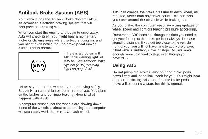
Antilock Brake System (ABS)Your vehicle has the Antilock Brake System (ABS),an advanced electronic braking system that willhelp prevent a braking skid.
When you start the engine and begin to drive away,ABS will check itself. You might hear a momentarymotor or clicking noise while this test is going on, andyou might even notice that the brake pedal movesa little. This is normal.
If there is a problem withABS, this warning light willstay on. See Antilock BrakeSystem (ABS) WarningLight on page 3-48.
Let us say the road is wet and you are driving safely.Suddenly, an animal jumps out in front of you. You slamon the brakes and continue braking. Here is whathappens with ABS:
A computer senses that the wheels are slowing down.If one of the wheels is about to stop rolling, the computerwill separately work the brakes at each wheel.
ABS can change the brake pressure to each wheel, asrequired, faster than any driver could. This can helpyou steer around the obstacle while braking hard.
As you brake, the computer keeps receiving updates onwheel speed and controls braking pressure accordingly.
Remember: ABS does not change the time you need toget your foot up to the brake pedal or always decreasestopping distance. If you get too close to the vehicle infront of you, you will not have time to apply the brakesif that vehicle suddenly slows or stops. Always leaveenough room up ahead to stop, even though youhave ABS.
Using ABSDo not pump the brakes. Just hold the brake pedaldown firmly and let antilock work for you. You might heara motor or clicking noise and feel the brake pedalmove a little during a stop, but this is normal.
5-5

Braking in EmergenciesWith ABS, you can steer and brake at the same time.In many emergencies, steering can help more than eventhe very best braking.
Brake AssistThis vehicle has a Brake Assist feature designed toassist the driver in stopping or decreasing vehicle speedin emergency driving conditions. This feature uses thestability system hydraulic brake control module tosupplement the power brake system under conditionswhere the driver has quickly and forcefully appliedthe brake pedal in an attempt to quickly stop or slowdown the vehicle. The stability system hydraulicbrake control module increases brake pressure at eachcorner of the vehicle until the ABS activates. Minorbrake pedal pulsations or pedal movement during thistime is normal and the driver should continue toapply the brake pedal as the driving situation dictatesThe Brake Assist feature will automatically disengagewhen the brake pedal is released or brake pedalpressure is quickly decreased.
StabiliTrak® SystemThe StabiliTrak System is a computer controlled systemthat helps the driver maintain directional control of thevehicle in difficult driving conditions. This is accomplishedby selectively applying any one of the vehicle’s brakes.
The Traction ControlSystem (TCS)/StabiliTraklight is located on theinstrument panel.
STABILITRAK ACTIVE comes on the Driver InformationCenter (DIC) when the system is working. See DICWarnings and Messages on page 3-60 for moreinformation. The system may be heard or felt while it isworking. This is normal.
The TCS/StabiliTrak light comes on the instrument panel,a chime will sound, and SERVICE STABILITRAK comeson the DIC if there is a problem with the system.
5-6

When this light and SERVICE STABILITRAK comes on,the system is not operational and needs to be serviced.Adjust your driving accordingly.
The system comes on automatically whenever thevehicle is started. To help maintain directional controlof the vehicle, the system should always be left on.The system can be turned off if needed. If the StabiliTraksystem is turned off, the Traction Control System willalso be turned off. Adjust your driving accordingly.
The Traction Controlbutton is located onthe console.
To turn the system off, press and hold the TCS/StabiliTrak button until the light comes on the instrumentpanel and STABILITRAK OFF comes on the DIC.
The system can be turned back on at any time bypressing the button. The TCS/StabiliTrak light turns offand STABILITRAK ON briefly comes on the DIC.
If the Tire Pressure Monitor (TPM) system detects a flattire and FLAT TIRE comes on the DIC, or if the TPMsystem is not working and SERVICE TIRE MONITORcomes on the DIC, StabiliTrak can be affected inthe following ways:
• StabiliTrak cannot be turned off by the driver.
• If StabiliTrak is off, it will be turned on automatically.
• Performance Mode is unavailable — XLR-V only.
5-7

Performance Mode — XLR-V OnlyNotice: When traction control is turned off, orPerformance Mode is active, it is possible to losetraction. If a shift is attempted with the rear wheelsspinning with a loss of traction, it is possible tocause damage to the transmission. Do not attempt toshift when the rear wheels do not have traction.Damage caused by misuse of the vehicle is notcovered. See the warranty book for additionalinformation.
For vehicles with this feature, the Performance Modecan be selected by pressing the TCS/StabiliTrak buttonon the console two times quickly. PERFORMANCEMODE comes on the DIC. Performance Mode allows thedriver to have full control of the rear wheels while theStabiliTrak System helps maintain directional control ofthe vehicle by applying the brakes as necessary.The TCS/StabiliTrak light will not be on. The TCS willnot be operating. Adjust your driving accordingly.
When the TCS/StabiliTrak button is pressed again, theStabiliTrak and Traction Control Systems will be on.The TRAC/STABILITRAK ON message will be displayedbriefly in the DIC and a chime will be heard.
Traction Control System (TCS)The vehicle has a traction control system that limitswheel spin. This is especially useful in slipperyroad conditions. The system operates only if it sensesthat one or both of the rear wheels are spinning orbeginning to lose traction. When this happens,the system works the rear brakes and reduces enginepower to limit wheel spin.
The TRAC SYSTEM ACTIVE message will display onthe Driver Information Center (DIC) when the tractioncontrol system is limiting wheel spin. See DIC Warningsand Messages on page 3-60. The system may beheard or felt while it is working, but this is normal.
If cruise control is being used when the traction controlsystem begins to limit wheel spin, the cruise controlwill automatically disengage. Cruise control may bereengaged when road conditions allow. See AdaptiveCruise Control on page 3-14 or Cruise Control onpage 3-11 for more information.
5-8

This warning light comeson if there is a problemwith the traction controlsystem.
See StabiliTrak®/Traction Control System (TCS) WarningLight on page 3-48. When this warning light is on, thesystem will not limit wheel spin. Adjust your drivingaccordingly.
The traction control system automatically comes onwhenever the vehicle is started. To limit wheel spin,especially in slippery road conditions, the system shouldalways be left on but can be turned off if needed. It maybe necessary to turn the system off if the vehicle is stuckin sand, mud or snow and rocking the vehicle is required.See Rocking Your Vehicle to Get It Out on page 5-20 andIf Your Vehicle is Stuck in Sand, Mud, Ice, or Snow onpage 5-20 for more information.
To turn the system off,press the traction controlbutton located on thecenter console.
The TRACTION SYSTEM OFF message will display onthe DIC and the traction control system warning light willcome on. If the system is limiting wheel spin when thebutton is pressed, the TRACTION SYSTEM OFFmessage will display – but the system will not turn off rightaway. It will wait until there is no longer a current need tolimit wheel spin.
The system can be turned back on at any time bypressing the button again. The TRACTION SYSTEM ONmessage should display briefly on the Driver InformationCenter. See DIC Warnings and Messages on page 3-60for more information.
Adding non-GM accessories can affect the vehicle’sperformance. See Accessories and Modificationson page 6-3 for more information.
5-9
Magnetic Ride Control™With this feature, Magnetic Ride Control automaticallyadjusts the ride of the vehicle based on drivingconditions. The controller receives input from the systemto determine the proper ride. If the controller detectsa problem within the system, the DIC will display aSERVICE RIDE CONTROL message. See DICWarnings and Messages on page 3-60 for moreinformation. See your dealer/retailer for service.
Limited-Slip Rear AxleVehicles with a limited-slip rear axle can give moretraction on snow, mud, ice, sand or gravel. It works likea standard axle most of the time, but when tractionis low, this feature allows the drive wheel with the mosttraction to move the vehicle.
Steering
Power SteeringIf you lose power steering assist because the enginestops or the system is not functioning, you can steer butit will take much more effort.
Magnetic Speed Variable AssistSteering SystemThis system continuously adjusts the effort you feelwhen steering at all vehicle speeds. It provides easewhen parking, yet a firm, solid feel at highway speeds.
Steering TipsIt is important to take curves at a reasonable speed.
Traction in a curve depends on the condition of the tiresand the road surface, the angle at which the curve isbanked, and your speed. While in a curve, speed is theone factor you can control.
If you need to reduce speed, do it before you enter thecurve, while the front wheels are straight ahead.
Try to adjust the speed so you can drive through thecurve. Maintain a reasonable, steady speed. Waitto accelerate until you are out of the curve, and thenaccelerate gently into the straightaway.
5-10

Steering in EmergenciesThere are times when steering can be more effective thanbraking. For example, you come over a hill and find atruck stopped in your lane, or a car suddenly pulls outfrom nowhere, or a child darts out from between parkedcars and stops right in front of you. You can avoid theseproblems by braking — if you can stop in time. Butsometimes you cannot; there is not room. That is the timefor evasive action — steering around the problem.
Your vehicle can perform very well in emergencies likethese. First apply the brakes. See Braking on page 5-4.It is better to remove as much speed as you can from apossible collision. Then steer around the problem, to theleft or right depending on the space available.
An emergency like this requires close attention and aquick decision. If you are holding the steering wheel atthe recommended 9 and 3 o’clock positions, youcan turn it a full 180 degrees very quickly withoutremoving either hand. But you have to act fast, steerquickly, and just as quickly straighten the wheelonce you have avoided the object.
The fact that such emergency situations are alwayspossible is a good reason to practice defensive drivingat all times and wear safety belts properly.
5-11

Off-Road RecoveryYour vehicle’s right wheels can drop off the edge of aroad onto the shoulder while driving.
If the level of the shoulder is only slightly below thepavement, recovery should be fairly easy. Ease off theaccelerator and then, if there is nothing in the way, steerso that your vehicle straddles the edge of the pavement.Turn the steering wheel 3 to 5 inches, 76 to 127 mm,(about one-eighth turn) until the right front tire contactsthe pavement edge. Then turn the steering wheel to gostraight down the roadway.
PassingPassing another vehicle on a two-lane road can bedangerous. To reduce the risk of danger while passing:
• Look down the road, to the sides, and to crossroadsfor situations that might affect a successful pass.If in doubt, wait.
• Watch for traffic signs, pavement markings, andlines that could indicate a turn or an intersection.Never cross a solid or double-solid line on your sideof the lane.
• Do not get too close to the vehicle you want topass. Doing so can reduce your visibility.
• Wait your turn to pass a slow vehicle.
• When you are being passed, ease to the right.
Loss of ControlLet us review what driving experts say about whathappens when the three control systems — brakes,steering, and acceleration — do not have enoughfriction where the tires meet the road to do what thedriver has asked.
In any emergency, do not give up. Keep trying tosteer and constantly seek an escape route or area ofless danger.
5-12

SkiddingIn a skid, a driver can lose control of the vehicle.Defensive drivers avoid most skids by taking reasonablecare suited to existing conditions, and by not overdrivingthose conditions. But skids are always possible.
The three types of skids correspond to your vehicle’sthree control systems. In the braking skid, the wheels arenot rolling. In the steering or cornering skid, too muchspeed or steering in a curve causes tires to slip and losecornering force. And in the acceleration skid, too muchthrottle causes the driving wheels to spin.
Remember: Any traction control system helps avoid onlythe acceleration skid. If your traction control systemis off, then an acceleration skid is best handledby easing your foot off the accelerator pedal.
If your vehicle starts to slide, ease your foot off theaccelerator pedal and quickly steer the way you wantthe vehicle to go. If you start steering quickly enough,your vehicle may straighten out. Always be readyfor a second skid if it occurs.
Of course, traction is reduced when water, snow, ice,gravel, or other material is on the road. For safety, youwill want to slow down and adjust your driving to theseconditions. It is important to slow down on slipperysurfaces because stopping distance will be longer andvehicle control more limited.
While driving on a surface with reduced traction, try yourbest to avoid sudden steering, acceleration, or braking,including reducing vehicle speed by shifting to a lowergear. Any sudden changes could cause the tires toslide. You may not realize the surface is slippery untilyour vehicle is skidding. Learn to recognize warningclues — such as enough water, ice, or packed snow onthe road to make a mirrored surface — and slow downwhen you have any doubt.
Remember: Any Antilock Brake System (ABS) helpsavoid only the braking skid.
5-13

Racing or Other Competitive Driving(XLR-V)See your warranty book before using your vehicle forracing or other competitive driving.
Notice: If you use your vehicle for racing or othercompetitive driving, the engine may use more oil thanit would with normal use. Low oil levels can damagethe engine. Be sure to check the oil level often duringracing or other competitive driving and keep the levelat or near 2 quarts (2 L) above the upper mark thatshows the proper operating range on the engine oildipstick. For information on how to add oil, seeEngine Oil on page 6-15. After the competitivedriving, remove excess oil so that the level on thedipstick is not above the upper mark that shows theproper operating range.
Driving at NightNight driving is more dangerous than day driving becausesome drivers are likely to be impaired — by alcohol ordrugs, with night vision problems, or by fatigue.
Night driving tips include:
• Drive defensively.
• Do not drink and drive.
• Reduce headlamp glare by adjusting the insiderearview mirror.
• Slow down and keep more space between you andother vehicles because headlamps can only light upso much road ahead.
• Watch for animals.
• When tired, pull off the road.
• Do not wear sunglasses.
• Avoid staring directly into approaching headlamps.
• Keep the windshield and all glass on your vehicleclean — inside and out.
• Keep your eyes moving, especially during turns orcurves.
No one can see as well at night as in the daytime.But, as we get older, these differences increase.A 50-year-old driver might need at least twice as muchlight to see the same thing at night as a 20-year-old.
5-14

Driving in Rain and on Wet RoadsRain and wet roads can reduce vehicle traction and affectyour ability to stop and accelerate. Always drive slowerin these types of driving conditions and avoid drivingthrough large puddles and deep-standing or flowingwater.
{CAUTION:
Wet brakes can cause crashes. They might notwork as well in a quick stop and could cause pullingto one side. You could lose control of the vehicle.
After driving through a large puddle of water or acar/vehicle wash, lightly apply the brake pedal untilthe brakes work normally.
Flowing or rushing water creates strong forces.Driving through flowing water could cause yourvehicle to be carried away. If this happens, you andother vehicle occupants could drown. Do not ignorepolice warnings and be very cautious about trying todrive through flowing water.
HydroplaningHydroplaning is dangerous. Water can build up underyour vehicle’s tires so they actually ride on thewater. This can happen if the road is wet enough andyou are going fast enough. When your vehicle ishydroplaning, it has little or no contact with the road.
There is no hard and fast rule about hydroplaning.The best advice is to slow down when the road is wet.
Other Rainy Weather TipsBesides slowing down, other wet weather driving tipsinclude:
• Allow extra following distance.
• Pass with caution.
• Keep windshield wiping equipment in good shape.
• Keep the windshield washer fluid reservoir filled.
• Have good tires with proper tread depth. See Tireson page 6-46.
• Turn off cruise control.
5-15

Before Leaving on a Long TripTo prepare your vehicle for a long trip, consider havingit serviced by your dealer/retailer before departing.
Things to check on your own include:
• Windshield Washer Fluid: Reservoir full? Windowsclean — inside and outside?
• Wiper Blades: In good shape?
• Fuel, Engine Oil, Other Fluids: All levels checked?
• Lamps: Do they all work and are lenses clean?
• Tires: Are treads good? Are tires inflated torecommended pressure?
• Weather and Maps: Safe to travel? Haveup-to-date maps?
Highway HypnosisAlways be alert and pay attention to your surroundingswhile driving. If you become tired or sleepy, find asafe place to park your vehicle and rest.
Other driving tips include:
• Keep the vehicle well ventilated.
• Keep interior temperature cool.
• Keep your eyes moving — scan the road aheadand to the sides.
• Check the rearview mirror and vehicle instrumentsoften.
5-16

Hill and Mountain RoadsDriving on steep hills or through mountains is differentthan driving on flat or rolling terrain. Tips for drivingin these conditions include:
• Keep the vehicle serviced and in good shape.
• Check all fluid levels and brakes, tires, coolingsystem, and transmission.
• Going down steep or long hills, shift to alower gear.
{CAUTION:
If you do not shift down, the brakes could get sohot that they would not work well. You would thenhave poor braking or even none going down a hill.You could crash. Shift down to let the engineassist the brakes on a steep downhill slope.
{CAUTION:
Coasting downhill in N (Neutral) or with the ignitionoff is dangerous. The brakes will have to do all thework of slowing down and they could get so hotthat they would not work well. You would thenhave poor braking or even none going down a hill.You could crash. Always have the engine runningand the vehicle in gear when going downhill.
• Stay in your own lane. Do not swing wide or cutacross the center of the road. Drive at speedsthat let you stay in your own lane.
• Top of hills: Be alert — something could be in yourlane (stalled car, accident).
• Pay attention to special road signs (falling rocksarea, winding roads, long grades, passing orno-passing zones) and take appropriate action.
5-17

Winter Driving
Driving on Snow or IceDrive carefully when there is snow or ice between thetires and the road, creating less traction or grip. Wet icecan occur at about 32°F (0°C) when freezing rainbegins to fall, resulting in even less traction. Avoiddriving on wet ice or in freezing rain until roads can betreated with salt or sand.
Drive with caution, whatever the condition. Accelerategently so traction is not lost. Accelerating too quicklycauses the wheels to spin and makes the surface underthe tires slick, so there is even less traction.
Try not to break the fragile traction. If you accelerate toofast, the drive wheels will spin and polish the surfaceunder the tires even more.
The Traction Control System (TCS) on page 5-8improves the ability to accelerate on slippery roads, butslow down and adjust your driving to the road conditions.The StabiliTrak® System on page 5-6 might also activate.When driving through deep snow, turn off the tractioncontrol system to help maintain vehicle motion at lowerspeeds.
The Antilock Brake System (ABS) on page 5-5 improvesvehicle stability during hard stops on a slippery roads,but apply the brakes sooner than when on drypavement.
Allow greater following distance on any slippery roadand watch for slippery spots. Icy patches can occur onotherwise clear roads in shaded areas. The surfaceof a curve or an overpass can remain icy whenthe surrounding roads are clear. Avoid sudden steeringmaneuvers and braking while on ice.
Turn off cruise control, if equipped, on slippery surfaces.
Blizzard ConditionsBeing stuck in snow can be in a serious situation.Stay with the vehicle unless there is help nearby.If possible, use the Roadside Service on page 8-7.To get help and keep everyone in the vehicle safe:
• Turn on the Hazard Warning Flashers on page 3-6.
• Tie a red cloth to an outside mirror.
5-18

{CAUTION:
Snow can trap engine exhaust under the vehicle.This may cause exhaust gases to get inside.Engine exhaust contains carbon monoxide (CO)which cannot be seen or smelled. It can causeunconsciousness and even death.If the vehicle is stuck in the snow:
• Clear away snow from around the base ofyour vehicle, especially any that is blockingthe exhaust pipe.
• Check again from time to time to be suresnow does not collect there.
• Open a window about two inches on the sideof the vehicle that is away from the wind tobring in fresh air.
• Fully open the air outlets on or under theinstrument panel.
• Adjust the Climate Control system to a settingthat circulates the air inside the vehicle andset the fan speed to the highest setting.See Climate Control System in the Index.
For more information about carbon monoxide,see Engine Exhaust on page 2-36.
CAUTION: (Continued)
CAUTION: (Continued)
Snow can trap exhaust gases under your vehicle.This can cause deadly CO (carbon monoxide) gasto get inside. CO could overcome you and kill you.You cannot see it or smell it, so you might notknow it is in your vehicle. Clear away snow fromaround the base of your vehicle, especially anythat is blocking the exhaust.
Run the engine for short periods only as needed tokeep warm, but be careful.
To save fuel, run the engine for only short periods asneeded to warm the vehicle and then shut the engine offand close the window most of the way to save heat.Repeat this until help arrives but only when youfeel really uncomfortable from the cold. Moving about tokeep warm also helps.
If it takes some time for help to arrive, now and thenwhen you run the engine, push the acceleratorpedal slightly so the engine runs faster than the idlespeed. This keeps the battery charged to restartthe vehicle and to signal for help with the headlamps.Do this as little as possible to save fuel.
5-19

If Your Vehicle is Stuck in Sand,Mud, Ice, or SnowSlowly and cautiously spin the wheels to free thevehicle when stuck in sand, mud, ice, or snow.See Rocking Your Vehicle to Get It Out on page 5-20.
If the vehicle has a traction system, it can often helpto free a stuck vehicle. Refer to the vehicle’s tractionsystem in the Index. If stuck too severely for the tractionsystem to free the vehicle, turn the traction system offand use the rocking method.
{CAUTION:
If you let your vehicle’s tires spin at high speed,they can explode, and you or others could beinjured. The vehicle can overheat, causing anengine compartment fire or other damage. Spin thewheels as little as possible and avoid going above35 mph (55 km/h) as shown on the speedometer.
For information about using tire chains on the vehicle,see Tire Chains on page 6-68.
Rocking Your Vehicle to Get It OutTurn the steering wheel left and right to clear the areaaround the front wheels. Turn off any traction or stabilitysystem. Shift back and forth between R (Reverse) and aforward gear, spinning the wheels as little as possible.To prevent transmission wear, wait until the wheels stopspinning before shifting gears. Release the acceleratorpedal while shifting, and press lightly on the acceleratorpedal when the transmission is in gear. Slowly spinningthe wheels in the forward and reverse directions causes arocking motion that could free the vehicle. If that does notget the vehicle out after a few tries, it might need to betowed out. If the vehicle does need to be towed out,see Towing Your Vehicle on page 5-26.
5-20

Loading the VehicleIt is very important to know how much weight yourvehicle can carry. This weight is called the vehiclecapacity weight and includes the weight of alloccupants, cargo, and all nonfactory-installedoptions. Two labels on your vehicle show how muchweight it may properly carry, the Tire and LoadingInformation label and the Certification label.
{CAUTION:
Do not load the vehicle any heavier than theGross Vehicle Weight Rating (GVWR), oreither the maximum front or rear Gross AxleWeight Rating (GAWR). If you do, parts on thevehicle can break, and it can change the wayyour vehicle handles. These could cause youto lose control and crash. Also, overloadingcan shorten the life of the vehicle.
Tire and Loading Information Label
A vehicle specific Tire and Loading Informationlabel is attached to the center pillar (B-pillar)of your vehicle. With the driver’s door open,you will find the label attached below the doorlatch. This label shows the number of occupantseating positions (A), and the maximum vehiclecapacity weight (B) in kilograms and pounds.
The Tire and Loading Information label also showsthe size of the original equipment tires (C) andthe recommended cold tire inflation pressures (D).
Label Example
5-21

For more information on tires and inflation seeTires on page 6-46 and Inflation - Tire Pressureon page 6-54.
There is also important loading information on thevehicle Certification label. It tells you the GrossVehicle Weight Rating (GVWR) and the Gross AxleWeight Rating (GAWR) for the front and rear axle.See “Certification Label” later in this section.
Steps for Determining Correct Load Limit1. Locate the statement “The combined weight of
occupants and cargo should never exceedXXX kg or XXX lbs” on your vehicle’s placard.
2. Determine the combined weight of the driverand passengers that will be riding in yourvehicle.
3. Subtract the combined weight of the driverand passengers from XXX kg or XXX lbs.
4. The resulting figure equals the availableamount of cargo and luggage load capacity.For example, if the “XXX” amount equals1400 lbs and there will be five 150 lbpassengers in your vehicle, the amount ofavailable cargo and luggage load capacity is650 lbs (1400 − 750 (5 x 150) = 650 lbs).
5. Determine the combined weight of luggageand cargo being loaded on the vehicle.That weight may not safely exceed theavailable cargo and luggage load capacitycalculated in Step 4.
6. If your vehicle will be towing a trailer, the loadfrom your trailer will be transferred to yourvehicle. Consult this manual to determine howthis reduces the available cargo and luggageload capacity of your vehicle.Your vehicle is neither designed nor intendedto tow a trailer.
5-22

Item Description Total
AVehicle CapacityWeight forExample 1 =
400 lbs (181 kg)
BSubtract OccupantWeight @ 150 lbs(68 kg) x 1 =
150 lbs (68 kg)
C Available Occupantand Cargo Weight = 250 lbs (113 kg)
Item Description Total
AVehicle CapacityWeight forExample 2 =
400 lbs (181 kg)
BSubtract OccupantWeight @ 150 lbs(68 kg) x 2 =
300 lbs (136 kg)
C Available CargoWeight = 100 lbs (45 kg)
Example 1 Example 2
5-23

Item Description Total
AVehicle CapacityWeight forExample 3 =
400 lbs (181 kg)
BSubtract OccupantWeight @ 200 lbs(91 kg) x 2 =
400 lbs (181 kg)
C Available CargoWeight = 0 lbs (0 kg)
Refer to your vehicle’s Tire and LoadingInformation label for specific information aboutyour vehicle’s capacity weight and seating
positions. The combined weight of the driver,passengers, and cargo should never exceed yourvehicle’s capacity weight.
Certification Label
A vehicle specific Certification label is attached tothe rear edge of the driver’s door. It tells youthe gross weight capacity of your vehicle, calledthe Gross Vehicle Weight Rating (GVWR).
Example 3
5-24

The GVWR includes the weight of the vehicle,all occupants, fuel, and cargo. Never exceed theGVWR for your vehicle, or the Gross Axle WeightRating (GAWR) for either the front or rear axle.
And, if you do have a heavy load, you shouldspread it out.
{CAUTION:
Do not load the vehicle any heavier than theGross Vehicle Weight Rating (GVWR), oreither the maximum front or rear Gross AxleWeight Rating (GAWR). If you do, parts on thevehicle can break, and it can change the wayyour vehicle handles. These could cause youto lose control and crash. Also, overloadingcan shorten the life of the vehicle.
Notice: Overloading your vehicle may causedamage. Repairs would not be covered by yourwarranty. Do not overload your vehicle.
If you put things inside your vehicle — likesuitcases, tools, packages, or anything else — theywill go as fast as the vehicle goes. If you have tostop or turn quickly, or if there is a crash, they willkeep going.
{CAUTION:
Things you put inside your vehicle can strikeand injure people in a sudden stop or turn, orin a crash.
• Put things in the rear area of yourvehicle. Try to spread the weight evenly.
• Never stack heavier things, likesuitcases, inside the vehicle so that someof them are above the tops of the seats.
• Do not leave an unsecured child restraintin your vehicle.
• When you carry something inside thevehicle, secure it whenever you can.
5-25

Towing
Towing Your VehicleConsult your dealer/retailer or a professional towingservice if the disabled vehicle needs to be towed.See Roadside Service on page 8-7.
Recreational Vehicle TowingNotice: Dolly towing or dinghy towing the vehiclemay cause damage because of reduced groundclearance. Always put the vehicle on a flatbed truck.
The vehicle was neither designed nor intended to betowed with any of its wheels on the ground. If the vehiclemust be towed, see “Towing Your Vehicle” earlier inthis section.
Towing a TrailerThe vehicle is neither designed nor intended to towa trailer.
5-26

Service ............................................................6-3Accessories and Modifications ..........................6-3California Proposition 65 Warning .....................6-4California Perchlorate Materials Requirements .....6-4Doing Your Own Service Work .........................6-4Adding Equipment to the Outside of the
Vehicle ......................................................6-5Fuel ................................................................6-5
Gasoline Octane ............................................6-5Gasoline Specifications ....................................6-6California Fuel ...............................................6-6Additives .......................................................6-6Fuels in Foreign Countries ...............................6-7Filling the Tank ..............................................6-8Filling a Portable Fuel Container .....................6-10
Checking Things Under the Hood ....................6-10Hood Release ..............................................6-11Engine Compartment Overview .......................6-12Engine Oil ...................................................6-15Engine Oil Life System ..................................6-18Engine Air Cleaner/Filter ................................6-20Automatic Transmission Fluid .........................6-21Cooling System ............................................6-22Engine Coolant .............................................6-23
Engine Overheating .......................................6-27Overheated Engine Protection
Operating Mode ........................................6-29Power Steering Fluid .....................................6-30Windshield Washer Fluid ................................6-31Brakes ........................................................6-32Battery ........................................................6-35Jump Starting ...............................................6-36
Rear Axle .......................................................6-41Headlamp Aiming ...........................................6-42
Headlamp Vertical Aiming ..............................6-43Bulb Replacement ..........................................6-45Windshield Replacement .................................6-45Windshield Wiper Blade Replacement ..............6-45Tires ..............................................................6-46
Winter Tires (XLR-V) .....................................6-47Tire Sidewall Labeling ...................................6-48Tire Terminology and Definitions .....................6-50Run-Flat Tires ..............................................6-52Inflation - Tire Pressure .................................6-54Tire Pressure Monitor System .........................6-55Tire Pressure Monitor Operation .....................6-57Tire Inspection and Rotation ...........................6-60
Section 6 Service and Appearance Care
6-1

When It Is Time for New Tires .......................6-61Buying New Tires .........................................6-62Different Size Tires and Wheels ......................6-63Uniform Tire Quality Grading ..........................6-64Wheel Alignment and Tire Balance ..................6-65Wheel Replacement ......................................6-66Tire Chains ..................................................6-68Lifting the Vehicle .........................................6-68If a Tire Goes Flat ........................................6-72
Appearance Care ............................................6-74Interior Cleaning ...........................................6-74Fabric/Carpet ...............................................6-75Leather .......................................................6-75Instrument Panel, Vinyl, and Other Plastic
Surfaces ..................................................6-76Wood Panels ...............................................6-76Speaker Covers ............................................6-76Care of Safety Belts ......................................6-76Weatherstrips ...............................................6-77Washing Your Vehicle ...................................6-77Cleaning Exterior Lamps/Lenses .....................6-77Finish Care ..................................................6-78
Windshield and Wiper Blades .........................6-78Aluminum or Chrome-Plated Wheels
and Trim ..................................................6-79Tires ...........................................................6-80Sheet Metal Damage .....................................6-80Finish Damage .............................................6-80Underbody Maintenance ................................6-80Fiberglass Springs (Composite Springs) ...........6-81Chemical Paint Spotting .................................6-81
Vehicle Identification ......................................6-81Vehicle Identification Number (VIN) .................6-81Service Parts Identification Label .....................6-82
Electrical System ............................................6-82Add-On Electrical Equipment ..........................6-82Windshield Wiper Fuses ................................6-83Power Windows and Other Power Options .......6-83Fuses and Circuit Breakers ............................6-83Instrument Panel Fuse Block ..........................6-83Underhood Fuse Block ..................................6-87
Capacities and Specifications ..........................6-90
Section 6 Service and Appearance Care
6-2

ServiceFor service and parts needs, visit your dealer/retailer.You will receive genuine GM parts and GM-trained andsupported service people.
Genuine GM parts have one of these marks:
Accessories and ModificationsWhen non-dealer/non-retailer accessories are added tothe vehicle, they can affect vehicle performance andsafety, including such things as airbags, braking, stability,ride and handling, emissions systems, aerodynamics,durability, and electronic systems like antilock brakes,traction control, and stability control. Some of theseaccessories could even cause malfunction or damage notcovered by the vehicle warranty.
Damage to vehicle components resulting from theinstallation or use of non-GM certified parts, includingcontrol module modifications, are not covered under theterms of the vehicle warranty and may affect remainingwarranty coverage for affected parts.
GM Accessories are designed to complement andfunction with other systems on the vehicle. YourGM dealer/retailer can accessorize the vehicle usinggenuine GM Accessories. When you go to yourGM dealer/retailer and ask for GM Accessories, you willknow that GM-trained and supported service technicianswill perform the work using genuine GM Accessories.
Also, see Adding Equipment to Your Airbag-EquippedVehicle on page 1-50.
6-3

California Proposition 65 WarningMost motor vehicles, including this one, contain and/oremit chemicals known to the State of California to causecancer and birth defects or other reproductive harm.Engine exhaust, many parts and systems (includingsome inside the vehicle), many fluids, and somecomponent wear by-products contain and/or emitthese chemicals.
California Perchlorate MaterialsRequirementsCertain types of automotive applications, such asairbag initiators, seat belt pretensioners, and lithiumbatteries contained in remote keyless transmitters,may contain perchlorate materials. Special handlingmay be necessary. For additional information, seewww.dtsc.ca.gov/hazardouswaste/perchlorate.
Doing Your Own Service Work
{CAUTION:
You can be injured and the vehicle could bedamaged if you try to do service work on a vehiclewithout knowing enough about it.
• Be sure you have sufficient knowledge,experience, the proper replacement parts,and tools before attempting any vehiclemaintenance task.
• Be sure to use the proper nuts, bolts, andother fasteners. English and metric fastenerscan be easily confused. If the wrong fastenersare used, parts can later break or fall off.You could be hurt.
6-4

If doing some of your own service work, use the properservice manual. It tells you much more about how toservice the vehicle than this manual can. To orderthe proper service manual, see Service PublicationsOrdering Information on page 8-15.
This vehicle has an airbag system. Before attemptingto do your own service work, see Servicing YourAirbag-Equipped Vehicle on page 1-50.
Keep a record with all parts receipts and list themileage and the date of any service work performed.See Maintenance Record on page 7-15.
Adding Equipment to the Outside ofthe VehicleThings added to the outside of the vehicle can affect theairflow around it. This can cause wind noise and canaffect fuel economy and windshield washer performance.Check with your dealer/retailer before adding equipmentto the outside of the vehicle.
FuelUse of the recommended fuel is an important part ofthe proper maintenance of this vehicle. To help keepthe engine clean and maintain optimum vehicleperformance, we recommend the use of gasolineadvertised as TOP TIER Detergent Gasoline.
The 8th digit of the Vehicle Identification Number (VIN)shows the code letter or number that identifies thevehicle’s engine. The VIN is at the top left of theinstrument panel. See Vehicle Identification Number(VIN) on page 6-81.
Gasoline OctaneIf the vehicle has the 4.6L V8 engine (VIN Code A), usepremium unleaded gasoline with a posted octane ratingof 91 or higher. You can also use regular unleadedgasoline rated at 87 octane or higher, but the vehicle’sacceleration could be slightly reduced, and you mightnotice a slight audible knocking noise, commonly referredto as spark knock. If the octane is less than 87, you mightnotice a heavy knocking noise when you drive. If thisoccurs, use a gasoline rated at 87 octane or higher assoon as possible. Otherwise, you could damage theengine. If you are using gasoline rated at 87 octane orhigher and you hear heavy knocking, the engine needsservice.
6-5

If the vehicle has the 4.4L V8 engine (VIN Code D),use premium unleaded gasoline with a posted octanerating of 91 or higher. For best performance, usepremium unleaded gasoline with a posted octanerating of 93. In an emergency, you can use regularunleaded gasoline with an octane rating of 87 or higher.If 87 octane fuel is used, do not perform any aggressivedriving maneuvers such as wide open throttleapplications. You might also hear audible spark knockduring acceleration. Refill the tank with premium fuel assoon as possible to avoid damaging the engine. If you areusing gasoline rated at 91 octane or higher and you hearheavy knocking, the engine needs service.
Gasoline SpecificationsAt a minimum, gasoline should meet ASTM specificationD 4814 in the United States or CAN/CGSB-3.5 or 3.511in Canada. Some gasolines contain an octane-enhancingadditive called methylcyclopentadienyl manganesetricarbonyl (MMT). We recommend against the use ofgasolines containing MMT. See Additives on page 6-6for additional information.
California FuelIf the vehicle is certified to meet California EmissionsStandards, it is designed to operate on fuels thatmeet California specifications. See the underhoodemission control label. If this fuel is not availablein states adopting California emissions standards, thevehicle will operate satisfactorily on fuels meeting federalspecifications, but emission control system performancemight be affected. The malfunction indicator lampcould turn on and the vehicle might fail a smog-checktest. See Malfunction Indicator Lamp on page 3-50.If this occurs, return to your authorized dealer/retailer fordiagnosis. If it is determined that the condition iscaused by the type of fuel used, repairs might not becovered by the vehicle warranty.
AdditivesTo provide cleaner air, all gasolines in the United Statesare now required to contain additives that help preventengine and fuel system deposits from forming, allowingthe emission control system to work properly. In mostcases, you should not have to add anything to the fuel.However, some gasolines contain only the minimumamount of additive required to meet U.S. EnvironmentalProtection Agency regulations. To help keep fuel injectors
6-6

and intake valves clean, or if the vehicle experiencesproblems due to dirty injectors or valves, look for gasolinethat is advertised as TOP TIER Detergent Gasoline.
For customers who do not use TOP TIER DetergentGasoline regularly, one bottle of GM Fuel SystemTreatment PLUS, added to the fuel tank at every engineoil change, can help clean deposits from fuel injectorsand intake valves. GM Fuel System Treatment PLUS isthe only gasoline additive recommended by GeneralMotors.
Also, your dealer/retailer has additives that will helpcorrect and prevent most deposit-related problems.
Gasolines containing oxygenates, such as ethers andethanol, and reformulated gasolines might be available inyour area. We recommend that you use these gasolines,if they comply with the specifications described earlier.However, E85 (85% ethanol) and other fuels containingmore than 10% ethanol must not be used in vehicles thatwere not designed for those fuels.
Notice: This vehicle was not designed for fuel thatcontains methanol. Do not use fuel containingmethanol. It can corrode metal parts in the fuelsystem and also damage plastic and rubber parts.That damage would not be covered under thevehicle warranty.
Some gasolines that are not reformulated for lowemissions can contain an octane-enhancing additivecalled methylcyclopentadienyl manganese tricarbonyl(MMT); ask the attendant where you buy gasolinewhether the fuel contains MMT. We recommend againstthe use of such gasolines. Fuels containing MMT canreduce the life of spark plugs and the performance ofthe emission control system could be affected.The malfunction indicator lamp might turn on. If thisoccurs, return to your dealer/retailer for service.
Fuels in Foreign CountriesIf you plan on driving in another country outside theUnited States or Canada, the proper fuel might be hardto find. Never use leaded gasoline or any other fuelnot recommended in the previous text on fuel. Costlyrepairs caused by use of improper fuel would notbe covered by the vehicle warranty.
To check the fuel availability, ask an auto club, orcontact a major oil company that does business in thecountry where you will be driving.
6-7

Filling the Tank
{CAUTION:
Fuel vapor burns violently and a fuel fire can causebad injuries. To help avoid injuries to you andothers, read and follow all the instructions on thepump island. Turn off the engine when you arerefueling. Do not smoke if you are near fuel orrefueling the vehicle. Do not use cellular phones.Keep sparks, flames, and smoking materials awayfrom fuel. Do not leave the fuel pump unattendedwhen refueling the vehicle. This is against the law insome places. Do not re-enter the vehicle whilepumping fuel. Keep children away from the fuelpump; never let children pump fuel.
The tethered fuel cap is located behind a hinged fueldoor on the driver side of the vehicle.
The fuel door releasebutton is located on the leftside of the instrumentpanel. The button onlyworks when the vehicle isin P (Park) or N (Neutral)and the valet lockout buttonis in OFF.
6-8

An alternate fuel doorrelease is located insidethe trunk behind a panel onthe driver side of thevehicle. Pull the handle torelease the fuel door.
To remove the fuel cap, turn it slowly counterclockwise.The fuel cap has a spring in it; if the cap is releasedtoo soon, it will spring back to the right.
While refueling, hang the tethered fuel cap from thehook on the fuel door.
{CAUTION:
Fuel can spray out on you if you open the fuel captoo quickly. If you spill fuel and then somethingignites it, you could be badly burned. This spraycan happen if the tank is nearly full, and is morelikely in hot weather. Open the fuel cap slowly andwait for any hiss noise to stop. Then unscrew thecap all the way.
Be careful not to spill fuel. Do not top off or overfill thetank and wait a few seconds after you have finishedpumping before removing the nozzle. Clean fuel frompainted surfaces as soon as possible. See WashingYour Vehicle on page 6-77.When replacing the fuel cap, turn it clockwise until itclicks. Make sure the cap is fully installed. The diagnosticsystem can determine if the fuel cap has been left off orimproperly installed. This would allow fuel to evaporateinto the atmosphere. See Malfunction Indicator Lamp onpage 3-50.The CHECK GAS CAP message in the Driver InformationCenter (DIC) will be displayed if the fuel cap is notproperly installed.
{CAUTION:
If a fire starts while you are refueling, do notremove the nozzle. Shut off the flow of fuel byshutting off the pump or by notifying the stationattendant. Leave the area immediately.
Notice: If you need a new fuel cap, be sure to get theright type. Your dealer/retailer can get one for you. Ifyou get the wrong type, it may not fit properly. Thismay cause the malfunction indicator lamp to lightand may damage the fuel tank and emissions system.See Malfunction Indicator Lamp on page 3-50.
6-9

Filling a Portable Fuel Container
{CAUTION:
Never fill a portable fuel container while it is in thevehicle. Static electricity discharge from thecontainer can ignite the fuel vapor. You can bebadly burned and the vehicle damaged if thisoccurs. To help avoid injury to you and others:
• Dispense fuel only into approved containers.• Do not fill a container while it is inside a
vehicle, in a vehicle’s trunk, pickup bed, or onany surface other than the ground.
• Bring the fill nozzle in contact with the insideof the fill opening before operating the nozzle.Contact should be maintained until the fillingis complete.
• Do not smoke while pumping fuel.• Do not use a cellular phone while
pumping fuel.
Checking Things Underthe Hood
{CAUTION:
An electric fan under the hood can start up andinjure you even when the engine is not running.Keep hands, clothing, and tools away from anyunderhood electric fan.
{CAUTION:
Things that burn can get on hot engine parts andstart a fire. These include liquids like fuel, oil,coolant, brake fluid, windshield washer and otherfluids, and plastic or rubber. You or others couldbe burned. Be careful not to drop or spill thingsthat will burn onto a hot engine.
6-10

Hood ReleaseTo lift the hood, use the following steps:
1. Pull the lever with thissymbol on it. It islocated on the lowerleft side of theinstrument panel.
2. Then go to the front of the vehicle and locate thesecondary hood release lever. The lever is underthe hood near the center of the vehicle. Movethe release lever to the right and raise the hood.
Before closing the hood, be sure all filler caps are onproperly. Then pull the hood down and close it firmly.
6-11

Engine Compartment OverviewWhen you open the hood on the 4.6L V8 engine, here is what you will see:
6-12

A. Battery. See Battery on page 6-35.B. Passenger Compartment Air Filter. See Passenger
Compartment Air Filter on page 3-41.C. Underhood Fuse Block. See Underhood Fuse Block
on page 6-87.D. Power Steering Fluid. See Power Steering Fluid on
page 6-30.E. Engine Air Cleaner/Filter. See Engine Air
Cleaner/Filter on page 6-20.F. Engine Oil Fill Cap. See “When to Add Engine Oil”
under Engine Oil on page 6-15.
G. Engine Oil Dipstick. See “Checking Engine Oil”under Engine Oil on page 6-15.
H. Brake Master Cylinder Reservoir. See “Brake Fluid”under Brakes on page 6-32.
I. Engine Coolant Surge Tank and Pressure Cap.See Cooling System on page 6-22.
J. Windshield Washer Fluid Reservoir. See “AddingWasher Fluid” under Windshield Washer Fluidon page 6-31.
6-13

When you open the hood on the 4.4L V8 XLR-V engine, here is what you will see:
6-14

A. Battery. See Battery on page 6-35.B. Passenger Compartment Air Filter. See Passenger
Compartment Air Filter on page 3-41.C. Underhood Fuse Block. See Underhood Fuse Block
on page 6-87.D. Power Steering Fluid. See Power Steering Fluid on
page 6-30.E. Engine Air Cleaner/Filter. See Engine Air
Cleaner/Filter on page 6-20.F. Engine Oil Fill Cap. See “When to Add Engine Oil”
under Engine Oil on page 6-15.G. Engine Oil Dipstick. See “Checking Engine Oil”
under Engine Oil on page 6-15.H. Brake Master Cylinder Reservoir. See “Brake Fluid”
under Brakes on page 6-32.I. Engine Coolant Surge Tank and Pressure Cap.
See Cooling System on page 6-22.J. Windshield Washer Fluid Reservoir. See “Adding
Washer Fluid” under Windshield Washer Fluidon page 6-31.
Engine OilIf the LOW OIL LEVEL or LOW OIL PRESSUREmessage on the Driver Information Center (DIC)appears, check the engine oil level right away.For more information, see LOW OIL LEVEL andLOW OIL PRESSURE under DIC Warnings andMessages on page 3-60. Check the engine oil levelregularly; this is an added reminder.
Checking Engine OilIt is a good idea to check the engine oil every time youget fuel. In order to get an accurate reading, the oilmust be warm and the vehicle must be on level ground.
The engine oil dipstick handle is a yellow loop. SeeEngine Compartment Overview on page 6-12 forthe location of the engine oil dipstick.
1. Turn off the engine and give the oil several minutesto drain back into the oil pan. If you do not do this,the oil dipstick might not show the actual level.
2. Pull out the dipstick and clean it with a paper towelor cloth, then push it back in all the way. Remove itagain, keeping the tip down, and check the level.
6-15

When to Add Engine Oil
If the oil is below the cross-hatched area at the tip of thedipstick, add at least one quart/liter of the recommendedoil. This section explains what kind of oil to use. Forengine oil crankcase capacity, see Capacities andSpecifications on page 6-90.
Notice: Do not add too much oil. If the engine hasso much oil that the oil level gets above thecross-hatched area that shows the proper operatingrange, the engine could be damaged.
See Engine CompartmentOverview on page 6-12 forthe location of the engineoil fill cap.
Add enough oil to put the level somewhere in the properoperating range. Push the dipstick all the way back inwhen you are through.
6-16

What Kind of Engine Oil to UseLook for three things:
• GM4718M
This vehicle’s engine requires a special oil meetingGM Standard GM4718M. Oils meeting this standardmay be identified as synthetic. However, not allsynthetic oils will meet this GM standard. Use onlyan oil that meets GM Standard GM4718M.
Notice: Using oils that do not have the GM4718MStandard designation can cause engine damage notcovered by the vehicle warranty.• SAE 5W-30
SAE 5W-30 is best for the vehicle. These numberson an oil container show its viscosity, or thickness.Do not use other viscosity oils such as SAE 20W-50.
• American Petroleum Institute (API) starburst symbolOils meeting theserequirements should havethe starburst symbol on thecontainer. This symbolindicates that the oil hasbeen certified by theAmerican PetroleumInstitute (API).
This vehicle’s engine was filled at the factory with aMobil 1® synthetic oil meeting all requirements for thisvehicle.Substitute Engine Oil: When adding oil to maintainengine oil level, oil meeting GM Standard GM4718Mmight not be available. You can add substitute oildesignated SAE 5W-30 with the starburst symbol atall temperatures. Substitute oil not meeting GMStandard GM4718M should not be used for an oilchange.
6-17
Engine Oil Additives / Engine OilFlushesDo not add anything to the oil. The recommended oilswith the starburst symbol that meet GM StandardGM4718M are all you need for good performance andengine protection.
Engine oil system flushes are not recommended andcould cause engine damage not covered by the vehiclewarranty.
Engine Oil Life System
When to Change Engine OilThis vehicle has a computer system that lets you knowwhen to change the engine oil and filter. This is based onengine revolutions and engine temperature, and not onmileage. Based on driving conditions, the mileage atwhich an oil change will be indicated can varyconsiderably. For the oil life system to work properly, youmust reset the system every time the oil is changed.
Notice: If this vehicle is an XLR-V model, the engineuses a special oil filter. The use of any other engineoil filter could lead to filter failure and result in severeengine damage. Damage caused by use of the wrongengine oil filter would not be covered by the vehiclewarranty.
When the system has calculated that oil life has beendiminished, it will indicate that an oil change isnecessary. A CHANGE OIL NOW message in the DICwill come on. See DIC Warnings and Messages onpage 3-60. Change the oil as soon as possible within thenext 600 miles (1 000 km). It is possible that, if youare driving under the best conditions, the oil life systemmight not indicate that an oil change is necessary forover a year. However, the engine oil and filter must bechanged at least once a year and at this time thesystem must be reset. Your dealer/retailer has trainedservice people who will perform this work using genuineparts and reset the system. It is also important tocheck the oil regularly and keep it at the proper level.
If the system is ever reset accidentally, you must changethe oil at 3,000 miles (5 000 km) since the last oil change.Remember to reset the oil life system whenever the oil ischanged.
6-18

How to Reset the Engine Oil LifeSystem and the Oil Life IndicatorThe Engine Oil Life System calculates when to changethe engine oil and filter based on vehicle use. Wheneverthe oil is changed, reset the system so it can calculatewhen the next oil change is required. If a situation occurswhere you change the oil prior to a CHANGE OIL NOWmessage in the DIC being turned on, reset the system.
After the oil has been changed, the CHANGE OIL NOWmessage and the oil life indicator must be reset. Toreset the message:
1. Press the up or down arrow to scroll the DIC toshow OIL LIFE.
2. Once the XXX% ENGINE OIL LIFE menu item ishighlighted, press and hold the RESET button untilthe percentage shows 100%.If the percentage does not return to 100% or if theCHANGE OIL NOW message comes back onwhen you start the vehicle, the engine oil life systemhas not reset. Repeat the procedure.
What to Do with Used OilUsed engine oil contains certain elements that can beunhealthy for your skin and could even cause cancer.Do not let used oil stay on your skin for very long.Clean your skin and nails with soap and water, or agood hand cleaner. Wash or properly dispose ofclothing or rags containing used engine oil. See themanufacturer’s warnings about the use and disposalof oil products.
Used oil can be a threat to the environment. If youchange your own oil, be sure to drain all the oil from thefilter before disposal. Never dispose of oil by putting itin the trash, pouring it on the ground, into sewers, or intostreams or bodies of water. Recycle it by taking it to aplace that collects used oil.
6-19
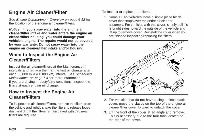
Engine Air Cleaner/FilterSee Engine Compartment Overview on page 6-12 forthe location of the engine air cleaner/filters.
Notice: If you spray water into the engine aircleaner/filter intake and water enters the engine aircleaner/filter housing, you could damage yourvehicle’s engine. The repairs would not be coveredby your warranty. Do not spray water into theengine air cleaner/filter intake and/or housing.
When to Inspect the Engine AirCleaner/FiltersInspect the air cleaner/filters at the Maintenance IIintervals and replace them at the first oil change aftereach 50,000 mile (80 000 km) interval. See ScheduledMaintenance on page 7-4 for more information.If you are driving in dusty/dirty conditions, inspect thefilters at each engine oil change.
How to Inspect the Engine AirCleaner/FiltersTo inspect the air cleaner/filters, remove the filters fromthe vehicle and lightly shake the filters to release loosedust and dirt. If the filters remain caked with dirt, newfilters are required.
To inspect or replace the filters:
1. Some XLR-V vehicles, have a single piece blackcover that snaps over the entire air cleanerassembly. For vehicles with this cover, simply pull it’sleft/right sides toward the outside of the vehicle andlift up to remove cover. Reinstall the cover when youare finished inspecting/replacing the filters.
2. For vehicles that do not have a single piece blackcover, move the clasps on the top of the engine aircleaner/filter cover forward to unlatch the cover.
3. Lift the front of the cover at an angle and remove.This is necessary due to the four tabs located onthe rear of the cover.
6-20

4. Remove the engine air cleaner/filter and any loosedebris that might be found in the air cleaner base.
5. Inspect or replace the filter.6. Repeat the procedure for the second air
cleaner/filter.
Reverse the procedure to reinstall the engine aircleaner/filter.
{CAUTION:
Operating the engine with the air cleaner/filter offcan cause you or others to be burned. The aircleaner not only cleans the air; it helps to stopflames if the engine backfires. If it is not there andthe engine backfires, you could be burned. Do notdrive with it off, and be careful working on theengine with the air cleaner/filter off.
Notice: If the air cleaner/filter is off, a backfire cancause a damaging engine fire. And, dirt can easily getinto the engine, which will damage it. Always havethe air cleaner/filter in place when you are driving.
Automatic Transmission FluidHow to Check AutomaticTransmission FluidIt is not necessary to check the transmission fluid level.A transmission fluid leak is the only reason for fluid loss.If a leak occurs, take the vehicle to the dealer/retailerservice department and have it repaired as soon aspossible.
There is a special procedure for checking and changingthe transmission fluid. Because this procedure isdifficult, you should have this done at the dealer/retailerservice department. Contact your dealer/retailer foradditional information or the procedure can be found inthe service manual. To purchase a service manual,see Service Publications Ordering Information onpage 8-15.
Notice: Use of the incorrect automatic transmissionfluid may damage the vehicle, and the damages maynot be covered by the vehicle’s warranty. Alwaysuse the automatic transmission fluid listed inRecommended Fluids and Lubricants on page 7-11.
Change the fluid and filter at the intervals listed inAdditional Required Services on page 7-6, and besure to use the fluid listed in Recommended Fluidsand Lubricants on page 7-11.
6-21

Cooling SystemThe cooling system allows the engine to maintain thecorrect working temperature.
A. Electric Engine Cooling FanB. Coolant Surge Tank with Pressure Cap
{CAUTION:
An electric engine cooling fan under the hood canstart up even when the engine is not running andcan cause injury. Keep hands, clothing, and toolsaway from any underhood electric fan.
{CAUTION:
Heater and radiator hoses, and other engine parts,can be very hot. Do not touch them. If you do, youcan be burned.Do not run the engine if there is a leak. If you runthe engine, it could lose all coolant. That couldcause an engine fire, and you could be burned.Get any leak fixed before you drive the vehicle.
Notice: Using coolant other than DEX-COOL® cancause premature engine, heater core, or radiatorcorrosion. In addition, the engine coolant couldrequire changing sooner, at 30,000 miles (50 000 km)or 24 months, whichever occurs first. Any repairswould not be covered by the vehicle warranty. Alwaysuse DEX-COOL® (silicate-free) coolant in the vehicle.
6-22

Engine CoolantThe cooling system in the vehicle is filled withDEX-COOL® engine coolant. This coolant isdesigned to remain in the vehicle for five years or150,000 miles (240 000 km), whichever occurs first.
The following explains the cooling system and how tocheck and add coolant when it is low. If there is aproblem with the engine overheating, see EngineOverheating on page 6-27.
What to Use
{CAUTION:
Adding only plain water to the cooling system canbe dangerous. Plain water, or some other liquidsuch as alcohol, can boil before the proper coolantmixture will. The vehicle’s coolant warning systemis set for the proper coolant mixture. With plainwater or the wrong mixture, the engine could gettoo hot but you would not get the overheatwarning. The engine could catch fire and you orothers could be burned. Use a 50/50 mixture ofclean, drinkable water and DEX-COOL® coolant.
Use a 50/50 mixture of clean, drinkable water andDEX-COOL® coolant. If using this mixture, nothing elseneeds to be added. This mixture:
• Gives freezing protection down to −34°F (−37°C),outside temperature.
• Gives boiling protection up to 265°F (129°C),engine temperature.
• Protects against rust and corrosion.
• Will not damage aluminum parts.
• Helps keep the proper engine temperature.
Notice: If an improper coolant mixture is used,the engine could overheat and be badly damaged.The repair cost would not be covered by the vehiclewarranty. Too much water in the mixture can freezeand crack the engine, radiator, heater core, andother parts.
Notice: If extra inhibitors and/or additives are usedin the vehicle’s cooling system, the vehicle couldbe damaged. Use only the proper mixture ofthe engine coolant listed in this manual for thecooling system. See Recommended Fluids andLubricants on page 7-11 for more information.
6-23

Checking CoolantThe vehicle must be on a level surface when checkingthe coolant level.
The engine coolant surge tank is located toward therear of the engine compartment on the driver side of thevehicle. For more information on location, see EngineCompartment Overview on page 6-12.
Check to see if coolant is visible in the coolant surge tank.If the coolant inside the coolant surge tank is boiling, donot do anything else until it cools down. If coolant isvisible but the coolant level is not at or above the FULLCOLD mark, add a 50/50 mixture of clean, drinkablewater and DEX-COOL® coolant at the coolant surge tank,but be sure the cooling system is cool before this is done.
When the engine is cold, the coolant level should be at orabove the FULL COLD mark on the side of the coolantsurge tank that faces the front. When the engine is hot,the level could be higher than the FULL COLD mark.
If the coolant is below the FULL COLD mark when theengine is hot, there could be a leak in the cooling system.
If the LOW COOLANT message on the Driver InformationCenter (DIC) comes on and stays on, it means thevehicle is low on engine coolant. See DIC Warnings andMessages on page 3-60. A low coolant level should beindicated by a LOW COOLANT message on the DriverInformation Center (DIC). If it is, there could be a leak inthe cooling system.
How to Add Coolant to the CoolantSurge Tank
{CAUTION:
You can be burned if you spill coolant on hotengine parts. Coolant contains ethylene glycol andit will burn if the engine parts are hot enough.Do not spill coolant on a hot engine.
6-24

Notice: This vehicle has a specific coolant fillprocedure. Failure to follow this procedure couldcause the engine to overheat and be severelydamaged.
{CAUTION:
An electric engine cooling fan under the hood canstart up even when the engine is not running andcan cause injury. Keep hands, clothing, and toolsaway from any underhood electric fan.
{CAUTION:
Steam and scalding liquids from a hot coolingsystem can blow out and burn you badly. They areunder pressure, and if you turn the coolant surgetank pressure cap — even a little — they can comeout at high speed. Never turn the cap when thecooling system, including the coolant surge tankpressure cap, is hot. Wait for the cooling systemand coolant surge tank pressure cap to cool if youever have to turn the pressure cap.
If no coolant is visible in the coolant surge tank, addcoolant as follows:
1. You can remove the coolant surge tank pressure capwhen the cooling system, including the coolant surgetank pressure cap and upper radiator hose, is nolonger hot. Turn the pressure cap slowlycounterclockwise.If you hear a hiss, wait for that to stop. A hissmeans there is still some pressure left.
2. Then keep turning the cap and remove it.
6-25

3. Fill the coolant surge tank with the proper mixtureuntil the level inside the coolant surge tank stabilizesat the FULL COLD mark on the front of the coolantsurge tank.
4. With the coolant surge tank pressure cap off, startthe engine and let it run until you can feel the upperradiator hose getting hot. Watch out for theengine cooling fan.By this time, the coolant level inside the coolantsurge tank may be lower. If the level is lower, addmore of the proper mixture to the coolant surge tankuntil the level stabilizes at the FULL COLD markon the coolant surge tank.
5. Then replace the pressure cap. Be sure the cap ishand-tight and fully seated.
6-26

If the LOW COOLANT message does not appear on theDriver Information Center (DIC) after two minutes, thecoolant is at the proper fill level. If a LOW COOLANTmessage does appear, repeat Steps 1 through 3 thenreinstall the pressure cap, or see your dealer/retailer.
If coolant is needed, add the proper DEX-COOL®
coolant mixture at the coolant surge tank.
Notice: If the pressure cap is not tightly installed,coolant loss and possible engine damage may occur.Be sure the cap is properly and tightly secured.
The coolant surge tank pressure cap must be fullyinstalled on the coolant surge tank. See EngineCompartment Overview on page 6-12 for moreinformation on location.
Engine OverheatingThe vehicle has several indicators to warn of engineoverheating.
There is a COOLANT OVER TEMP message or anENGINE HOT, STOP ENGINE message displayed in theDriver Information Center (DIC). See DIC Warningsand Messages on page 3-60. You will also hear a chime.
There is also an engine coolant temperature gage onthe instrument panel cluster. See Engine CoolantTemperature Gage on page 3-49.
You may decide not to lift the hood when this warningappears, but instead get service help right away.See Roadside Service on page 8-7.
If you do decide to lift the hood, make sure the vehicleis parked on a level surface.
Then check to see if the engine cooling fans arerunning. If the engine is overheating, both fans shouldbe running. If they are not, do not continue to runthe engine and have the vehicle serviced.
Notice: Engine damage from running the enginewithout coolant is not covered by the warranty.
Notice: If the engine catches fire while drivingwith no coolant, the vehicle can be badly damaged.The costly repairs would not be covered by thevehicle warranty. See Overheated Engine ProtectionOperating Mode on page 6-29 for information ondriving to a safe place in an emergency.
6-27

If Steam Is Coming From The EngineCompartment
{CAUTION:
Steam from an overheated engine can burn youbadly, even if you just open the hood. Stay awayfrom the engine if you see or hear steam comingfrom it. Turn it off and get everyone away from thevehicle until it cools down. Wait until there is no signof steam or coolant before you open the hood.
If you keep driving when the vehicles engine isoverheated, the liquids in it can catch fire. You orothers could be badly burned. Stop the engine if itoverheats, and get out of the vehicle until theengine is cool.
See Overheated Engine Protection Operating Modeon page 6-29 for information on driving to a safeplace in an emergency.
If No Steam Is Coming From TheEngine CompartmentAn overheat warning, along with a low coolant message,can indicate a serious problem.
If an engine overheat warning is displayed with no lowcoolant message, but no steam can be seen orheard, the problem may not be too serious. Sometimesthe engine can get a little too hot when the vehicle:
• Climbs a long hill on a hot day.
• Stops after high-speed driving.
• Idles for long periods in traffic.
• Tows a trailer.
6-28

If the overheat warning is displayed with no sign ofsteam, try this for a minute or so:
1. Turn the air conditioning off.
2. Turn the heater on to the highest temperature andto the highest fan speed. Open the windows asnecessary.
3. In heavy traffic, let the engine idle in N (Neutral)while stopped. If it is safe to do so, pull off theroad, shift to P (Park) or N (Neutral) and letthe engine idle.
If the temperature overheat gage is no longer in theoverheat zone or an overheat warning no longer displays,the vehicle can be driven. Continue to drive the vehicleslow for about 10 minutes. Keep a safe vehicle distancefrom the car in front of you. If the warning does not comeback on, continue to drive normally.
If the warning continues, pull over, stop, and park thevehicle right away.
If there is no sign of steam, idle the engine forthree minutes while parked. If the warning is stilldisplayed, turn off the engine until it cools down. Also,see “Overheated Engine Protection Operating Mode”next in this section.
Overheated Engine ProtectionOperating ModeThis operating mode allows the vehicle to be driven to asafe place in an emergency situation. If an overheatedengine condition exists and the DIC message ENGINEHOT, STOP ENGINE is displayed, an overheatprotection mode which alternates firing groups ofcylinders helps prevent engine damage. In this mode,you will notice a significant loss in power and engineperformance. Driving extended miles (km) in theoverheat protection mode should be avoided.
Notice: After driving in the overheated engineprotection operating mode, to avoid engine damage,allow the engine to cool before attempting any repair.The engine oil will be severely degraded. Repair thecause of coolant loss, change the oil and reset the oillife system. See Engine Oil on page 6-15.
6-29

Power Steering Fluid
See Engine CompartmentOverview on page 6-12 forreservoir location.
When to Check Power Steering FluidIt is not necessary to regularly check power steering fluidunless you suspect there is a leak in the system or youhear an unusual noise. A fluid loss in this system couldindicate a problem. Have the system inspected andrepaired.
How to Check Power Steering FluidTo check the power steering fluid:
1. Turn the ignition off and let the engine compartmentcool down.
2. Wipe the cap and the top of the reservoir clean.
3. Unscrew the cap and wipe the dipstick with aclean rag.
4. Replace the cap and completely tighten it.
5. Remove the cap again and look at the fluid level onthe dipstick.
The level should be at the FULL COLD mark.If necessary, add only enough fluid to bring thelevel up to the mark.
What to UseTo determine what kind of fluid to use, seeRecommended Fluids and Lubricants on page 7-11.Always use the proper fluid.
Notice: Use of the incorrect fluid may damage thevehicle and the damages may not be covered by thevehicle’s warranty. Always use the correct fluidlisted in Recommended Fluids and Lubricants onpage 7-11.
6-30

Windshield Washer Fluid
What to UseWhen you need windshield washer fluid, be sure to readthe manufacturer’s instructions before use. If you will beoperating the vehicle in an area where the temperaturemay fall below freezing, use a fluid that has sufficientprotection against freezing.
Adding Washer FluidThe LOW WASHER FLUID message will be displayed onthe Driver Information Center (DIC) when the fluid is low.
Open the cap with thewasher symbol on it. Addwasher fluid until thetank is full. See EngineCompartment Overview onpage 6-12 for reservoirlocation.
Notice:
• When using concentrated washer fluid, follow themanufacturer’s instructions for adding water.
• Do not mix water with ready-to-use washer fluid.Water can cause the solution to freeze anddamage your washer fluid tank and other parts ofthe washer system. Also, water does not clean aswell as washer fluid.
• Fill the washer fluid tank only three-quarters fullwhen it is very cold. This allows for fluidexpansion if freezing occurs, which coulddamage the tank if it is completely full.
• Do not use engine coolant (antifreeze) in yourwindshield washer. It can damage the vehicle’swindshield washer system and paint.
6-31

Brakes
Brake Fluid
The brake master cylinderreservoir is filled withDOT-3 brake fluid. SeeEngine CompartmentOverview on page 6-12 forthe location of the reservoir.
There are only two reasons why the brake fluid level inthe reservoir might go down:
• The brake fluid level goes down because of normalbrake lining wear. When new linings are installed,the fluid level goes back up.
• A fluid leak in the brake hydraulic system can alsocause a low fluid level. Have the brake hydraulicsystem fixed, since a leak means that sooneror later the brakes will not work well.
Do not top off the brake fluid. Adding fluid does notcorrect a leak. If fluid is added when the liningsare worn, there will be too much fluid when new brakelinings are installed. Add or remove brake fluid, asnecessary, only when work is done on the brakehydraulic system.
{CAUTION:
If too much brake fluid is added, it can spill on theengine and burn, if the engine is hot enough. Youor others could be burned, and the vehicle couldbe damaged. Add brake fluid only when work isdone on the brake hydraulic system. See“Checking Brake Fluid” in this section.
Refer to the Maintenance Schedule to determine whento check the brake fluid. See Scheduled Maintenanceon page 7-4.
6-32

Checking Brake FluidCheck brake fluid by looking at the brake fluid reservoir.See Engine Compartment Overview on page 6-12.
The fluid level should be above the MIN mark on thereservoir. If it is not, have the brake hydraulic systemchecked to see if there is a leak.
After work is done on the brake hydraulic system, makesure the level is between the MIN and MAX marks.
What to AddUse only new DOT-3 brake fluid from a sealedcontainer. See Recommended Fluids and Lubricants onpage 7-11.
Always clean the brake fluid reservoir cap and the areaaround the cap before removing it. This helps keepdirt from entering the reservoir.
{CAUTION:
With the wrong kind of fluid in the brake hydraulicsystem, the brakes might not work well. This couldcause a crash. Always use the proper brake fluid.
Notice:
• Using the wrong fluid can badly damage brakehydraulic system parts. For example, just afew drops of mineral-based oil, such as engineoil, in the brake hydraulic system can damagebrake hydraulic system parts so badly that theywill have to be replaced. Do not let someoneput in the wrong kind of fluid.
• If brake fluid is spilled on the vehicle’s paintedsurfaces, the paint finish can be damaged. Becareful not to spill brake fluid on the vehicle.If you do, wash it off immediately. See WashingYour Vehicle on page 6-77.
6-33

Brake WearThis vehicle has disc brakes. Disc brake pads havebuilt-in wear indicators that make a high-pitched warningsound when the brake pads are worn and new padsare needed. The sound can come and go or be heard allthe time the vehicle is moving, except when applyingthe brake pedal firmly.
{CAUTION:
The brake wear warning sound means that soonthe brakes will not work well. That could lead to anaccident. When the brake wear warning sound isheard, have the vehicle serviced.
Notice: Continuing to drive with worn-out brakepads could result in costly brake repair.
Some driving conditions or climates can cause a brakesqueal when the brakes are first applied or lightly applied.This does not mean something is wrong with the brakes.
Brake linings should always be replaced as completeaxle sets.
Brake Pedal TravelSee your dealer/retailer if the brake pedal does notreturn to normal height, or if there is a rapid increase inpedal travel. This could be a sign that brake servicemight be required.
Brake AdjustmentEvery brake stop, the disc brakes automatically adjustfor wear.
6-34

Replacing Brake System PartsThe braking system on a vehicle is complex. Its manyparts have to be of top quality and work well together ifthe vehicle is to have really good braking. The vehiclewas designed and tested with top-quality brake parts.When parts of the braking system are replaced — forexample, when the brake linings wear down and newones are installed — be sure to get new approvedreplacement parts. If this is not done, the brakes mightnot work properly. For example, if someone puts in brakelinings that are wrong for the vehicle, the balancebetween the front and rear brakes can change — for theworse. The braking performance expected can change inmany other ways if the wrong replacement brake partsare installed.
BatteryThis vehicle has a maintenance free battery. When it istime for a new battery, see your dealer/retailer forone that has the replacement number shown on theoriginal battery’s label.
For battery replacement, see your dealer/retailer or theservice manual. To purchase a service manual, seeService Publications Ordering Information on page 8-15.
Warning: Battery posts, terminals, and relatedaccessories contain lead and lead compounds,chemicals known to the State of California to causecancer and reproductive harm. Wash hands afterhandling.
6-35

Vehicle Storage
{CAUTION:
Batteries have acid that can burn you and gas thatcan explode. You can be badly hurt if you are notcareful. See Jump Starting on page 6-36 for tipson working around a battery without getting hurt.
Infrequent Usage: If the vehicle is driven infrequently,remove the black, negative (−) cable from the battery.This helps keep the battery from running down.
See “Power Window Initialization” in Power Windows onpage 2-18.
Extended Storage: For extended storage of the vehicle,remove the black, negative (−) cable from the battery oruse a battery trickle charger. This helps maintain thecharge of the battery over an extended period of time.
All doors and the trunk must be closed beforereconnecting the battery. After reconnecting the battery,press the unlock button on the keyless accesstransmitter. Failure to follow this procedure could resultin the alarm sounding. Pressing unlock on the keylessaccess transmitter will stop the alarm.
Jump StartingIf the vehicle’s battery has run down, you may want touse another vehicle and some jumper cables to startyour vehicle. Be sure to use the following steps to do itsafely.
{CAUTION:
Batteries can hurt you. They can be dangerousbecause:
• They contain acid that can burn you.• They contain gas that can explode or ignite.• They contain enough electricity to burn you.
If you do not follow these steps exactly, some orall of these things can hurt you.
6-36

Notice: If you try to start your vehicle by pushingor pulling it, you could damage your vehicle. Do notpush or pull your vehicle to start it; instead, usethe jump starting procedure in this manual to startyour vehicle when the battery has run down.
1. Check the other vehicle. It must have a 12-voltbattery with a negative ground system.
Notice: If the other vehicle’s system is not a 12-voltsystem with a negative ground, both vehicles canbe damaged. Only use vehicles with 12-volt systemswith negative grounds to jump start your vehicle.
2. Get the vehicles close enough so the jumper cablescan reach, but be sure the vehicles are not touchingeach other. If they are, it could cause a groundconnection you do not want. You would not be ableto start your vehicle, and the bad groundingcould damage the electrical systems.To avoid the possibility of the vehicles rolling, setthe parking brake firmly on both vehicles involved inthe jump start procedure. Put an automatictransmission in P (Park) or a manual transmissionin NEUTRAL before setting the parking brake.
Notice: If you leave the radio or other accessorieson during the jump starting procedure, they could bedamaged. The repairs would not be covered by thewarranty. Always turn off the radio and otheraccessories when jump starting the vehicle.
3. Turn off the ignition on both vehicles. Unplugunnecessary accessories plugged into the cigarettelighter or the accessory power outlet. Turn offthe radio and all lamps that are not needed. Thiswill avoid sparks and help save both batteries. Andit could save the radio!
4. Open the hoods and locate the batteries. Find thepositive (+) and negative (−) terminal locations oneach vehicle. See Engine Compartment Overviewon page 6-12 for more information on location.
{CAUTION:
An electric fan can start up even when the engineis not running and can injure you. Keep hands,clothing and tools away from any underhoodelectric fan.
6-37

{CAUTION:
Using a match near a battery can cause batterygas to explode. People have been hurt doing this,and some have been blinded. Use a flashlight ifyou need more light.
Be sure the battery has enough water. You do notneed to add water to the battery installed in yournew vehicle. But if a battery has filler caps, besure the right amount of fluid is there. If it is low,add water to take care of that first. If you do not,explosive gas could be present.
Battery fluid contains acid that can burn you.Do not get it on you. If you accidentally get it inyour eyes or on your skin, flush the place withwater and get medical help immediately.
{CAUTION:
Fans or other moving engine parts can injure youbadly. Keep your hands away from moving partsonce the engine is running.
5. Check that the jumper cables do not have loose ormissing insulation. If they do, you could get ashock. The vehicles could be damaged too.Before you connect the cables, here are somebasic things you should know. Positive (+) will go topositive (+) or to a remote positive (+) terminal ifthe vehicle has one. Negative (−) will go to a heavy,unpainted metal engine part or to a remotenegative (−) terminal if the vehicle has one.Do not connect positive (+) to negative (−) or you willget a short that would damage the battery and maybeother parts too. And do not connect the negative (−)cable to the negative (−) terminal on the dead batterybecause this can cause sparks.
6-38

6. Connect the red positive (+) cable to the positive (+)terminal of the dead battery. Use a remotepositive (+) terminal if the vehicle has one.
7. Do not let the other end touch metal. Connect it tothe positive (+) terminal of the good battery. Use aremote positive (+) terminal if the vehicle has one.
8. Now connect the black negative (−) cable tothe negative (−) terminal of the good battery.Use a remote negative (−) terminal if the vehiclehas one.Do not let the other end touch anything until thenext step. The other end of the negative (−) cabledoes not go to the dead battery. It goes to aheavy, unpainted metal engine part or to a remotenegative (−) terminal on the vehicle with thedead battery.
9. Connect the other end of the negative (−) cableat least 18 inches (45 cm) away from the deadbattery, but not near engine parts that move. Theelectrical connection is just as good there, andthe chance of sparks getting back to the batteryis much less.
10. Now start the vehicle with the good battery and runthe engine for a while.
11. Try to start the vehicle that had the dead battery.If it will not start after a few tries, it probablyneeds service.
6-39
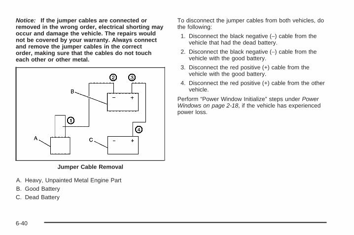
Notice: If the jumper cables are connected orremoved in the wrong order, electrical shorting mayoccur and damage the vehicle. The repairs wouldnot be covered by your warranty. Always connectand remove the jumper cables in the correctorder, making sure that the cables do not toucheach other or other metal.
A. Heavy, Unpainted Metal Engine PartB. Good BatteryC. Dead Battery
To disconnect the jumper cables from both vehicles, dothe following:
1. Disconnect the black negative (−) cable from thevehicle that had the dead battery.
2. Disconnect the black negative (−) cable from thevehicle with the good battery.
3. Disconnect the red positive (+) cable from thevehicle with the good battery.
4. Disconnect the red positive (+) cable from the othervehicle.
Perform “Power Window Initialize” steps under PowerWindows on page 2-18, if the vehicle has experiencedpower loss.
Jumper Cable Removal
6-40

Rear AxleWhen to Check LubricantIt is not necessary to regularly check rear axle fluidunless you suspect there is a leak or you hear anunusual noise. A fluid loss could indicate a problem.Have it inspected and repaired.
How to Check Lubricant
To get an accurate reading, the vehicle should be on alevel surface.
If the level is below the bottom of the filler plug hole, youwill need to add some lubricant. Add enough lubricant toraise the level to the bottom of the filler plug hole.
What to UseTo add lubricant when the level is low, useDexron LS Gear Oil or equivalent meetingGM Specification 9986115. To completely refill afterdraining, add 4.7 ounces (118 ml) of Limited-SlipDifferential Lubricant Additive (GM Part No. 1052358) orequivalent. Then fill to the bottom of the filler plughole with the Synthetic Gear Lubricant.
6-41

Headlamp AimingThe high intensity discharge (HID) visual optical aimingtype headlamps have been preset at the factory andshould need no further adjustment. If the headlampsneed to be re-aimed, it is recommended to see yourdealer/retailer for service. However, it is possible tore-aim the headlamps as described in the followingprocedure.
Notice: To make sure the headlamps are aimedproperly, read all the instructions before beginning.Failure to follow these instructions could causedamage to headlamp parts.
The vehicle should be properly prepared as follows:
• The vehicle should be placed so the headlamps are25 ft (7.6 m) from a light colored wall.
• The vehicle must have all four tires on a perfectlylevel surface which is level all the way to the wall.
• The vehicle should be placed so it is perpendicularto the wall.
• The vehicle should not have any snow, ice, or mudattached to it.
• The vehicle should be fully assembled all otherwork stopped while headlamp aiming is being done.
• The vehicle should be normally loaded with afull tank of fuel and one person or 160 lbs (75 kg) onthe driver seat.
• The tires should be properly inflated.
• Start the vehicle and rock it to level the suspension.
Headlamp aiming is done with the low-beamheadlamps. The high-beam headlamps are correctlyaimed if the low-beam headlamps are aimed properly.
The headlamp aimingdevice is under the hoodnear the headlamps.
6-42

Headlamp Vertical AimingTo properly prepare the vehicle for vertical headlampaiming, see Headlamp Aiming on page 6-42 formore information.
Notice: Horizontal aiming must be performedbefore making any adjustments to the vertical aim.Adjusting the vertical aim first will result in anincorrect headlamp aim.
To adjust the vertical aim:
1. Open the hood. See Hood Release on page 6-11for more information.
2. Locate the aim dot on the inner projector lens of thelow-beam headlamp.
3. Measure the distance from the ground to the aimdot on each low-beam headlamp. Record thisdistance.
4. At the wall or other flat surface, measure from theground upward (A) to the recorded distance fromStep 3 and mark it.
Notice: Do not cover a headlamp to improve beamcut-off when aiming. Covering a headlamp maycause excessive heat build-up which may causedamage to the headlamp.
5. Draw or tape a horizontal line (B) on the wall or flatsurface the width of the vehicle at the height of themark in Step 4.
6. Turn on the low-beam headlamps and place apiece of cardboard in front of the headlamp notbeing aimed. This should allow only the beam oflight from the headlamp being aimed to be seen onthe flat surface.
6-43

7. Locate the vertical headlamp aiming screws, whichare under the hood near each headlamp assembly.The adjustment screw can be turned with a6 mm male hex.
8. Turn the verticalaiming screw until theheadlamp beam isaimed to the horizontaltape line.
9. The top edge of the cut-off should be positioned atthe bottom edge of the horizontal tape line.
10. Make sure that the light from the headlamp ispositioned at the bottom edge of the horizontal tapeline. The lamp on the left (A) shows the correctheadlamp aim. The lamp on the right (B) shows theincorrect headlamp aim.
11. Repeat Steps 7 through 9 for the oppositeheadlamp.
6-44
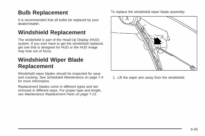
Bulb ReplacementIt is recommended that all bulbs be replaced by yourdealer/retailer.
Windshield ReplacementThe windshield is part of the Head-Up Display (HUD)system. If you ever have to get the windshield replaced,get one that is designed for HUD or the HUD imagemay look out of focus.
Windshield Wiper BladeReplacementWindshield wiper blades should be inspected for wearand cracking. See Scheduled Maintenance on page 7-4for more information.
Replacement blades come in different types and areremoved in different ways. For proper type and length,see Maintenance Replacement Parts on page 7-13.
To replace the windshield wiper blade assembly:
1. Lift the wiper arm away from the windshield.
6-45
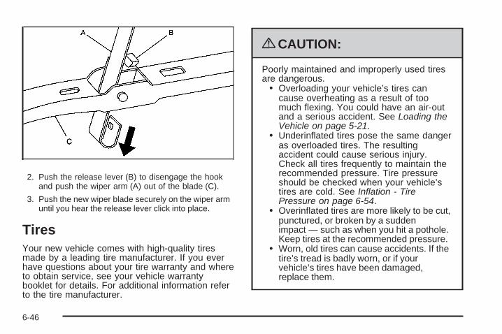
2. Push the release lever (B) to disengage the hookand push the wiper arm (A) out of the blade (C).
3. Push the new wiper blade securely on the wiper armuntil you hear the release lever click into place.
TiresYour new vehicle comes with high-quality tiresmade by a leading tire manufacturer. If you everhave questions about your tire warranty and whereto obtain service, see your vehicle warrantybooklet for details. For additional information referto the tire manufacturer.
{CAUTION:
Poorly maintained and improperly used tiresare dangerous.
• Overloading your vehicle’s tires cancause overheating as a result of toomuch flexing. You could have an air-outand a serious accident. See Loading theVehicle on page 5-21.
• Underinflated tires pose the same dangeras overloaded tires. The resultingaccident could cause serious injury.Check all tires frequently to maintain therecommended pressure. Tire pressureshould be checked when your vehicle’stires are cold. See Inflation - TirePressure on page 6-54.
• Overinflated tires are more likely to be cut,punctured, or broken by a suddenimpact — such as when you hit a pothole.Keep tires at the recommended pressure.
• Worn, old tires can cause accidents. If thetire’s tread is badly worn, or if yourvehicle’s tires have been damaged,replace them.
6-46

Low-Profile Tires (XLR-V)If your vehicle has P235/45R19 or P255/40R19size tires, they are classified as low-profile tires.These tires are designed for very responsive drivingon wet or dry pavement. You may also notice moreroad noise with low-profile performance tires andthat they tend to wear faster.
Notice: If the vehicle has low-profile tires,they are more susceptible to damage from roadhazards or curb impact than standard profiletires. Tire and/or wheel assembly damagecan occur when coming into contact with roadhazards like, potholes, or sharp edgedobjects, or when sliding into a curb. Thevehicle warranty does not cover this type ofdamage. Keep tires set to the correct inflationpressure and, when possible avoid contactwith curbs, potholes, and other road hazards.
Winter Tires (XLR-V)If you expect to drive on snow or ice covered roadsoften, you may want to get winter tires for your vehicle.All season tires provide good overall performance onmost surfaces but they may not offer the tractionyou would like or the same level of performance aswinter tires on snow or ice covered roads.
Winter tires, in general, are designed for increasedtraction on snow and ice covered roads. With wintertires, there may be decreased dry road traction,increased road noise, and shorter tread life. Afterswitching to winter tires, be alert for changes in vehiclehandling and braking.
See your dealer for details regarding winter tireavailability and proper tire selection. Also, see BuyingNew Tires on page 6-62.
If you choose to use winter tires:
• Use tires of the same brand and tread type on allfour wheel positions.
• Use only radial ply tires of the same size, loadrange, and speed rating as the original equipmenttires.
Winter tires with the same speed rating as your originalequipment tires may not be available for H, V, W, Y,and ZR speed rated tires. If you choose winter tires witha lower speed rating, never exceed the tire’s maximumspeed capability.
6-47

Tire Sidewall LabelingUseful information about a tire is molded into itssidewall. The example below shows a typicalpassenger (p-metric) tire sidewall.
(A) Tire Size: The tire size is a combination ofletters and numbers used to define a particular tire’swidth, height, aspect ratio, construction type, andservice description. See the “Tire Size” illustrationlater in this section for more detail.
(B) TPC Spec (Tire Performance CriteriaSpecification): Original equipment tires designedto GM’s specific tire performance criteria havea TPC specification code molded onto the sidewall.GM’s TPC specifications meet or exceed allfederal safety guidelines.
(C) DOT (Department of Transportation):The Department of Transportation (DOT) codeindicates that the tire is in compliance with theU.S. Department of Transportation Motor VehicleSafety Standards.
(D) Tire Identification Number (TIN): The lettersand numbers following DOT code are the TireIdentification Number (TIN). The TIN showsthe manufacturer and plant code, tire size, anddate the tire was manufactured. The TIN is moldedonto both sides of the tire, although only oneside may have the date of manufacture.
(E) Tire Ply Material: The type of cord andnumber of plies in the sidewall and under thetread.
Passenger (P-Metric) Tire Example
6-48

(F) Uniform Tire Quality Grading (UTQG):Tire manufacturers are required to grade tiresbased on three performance factors: treadwear,traction and temperature resistance. For moreinformation see Uniform Tire Quality Grading onpage 6-64.
(G) Maximum Cold Inflation Load Limit:Maximum load that can be carried and themaximum pressure needed to support that load.
Tire SizeThe following illustration shows an example of atypical passenger (p-metric) vehicle tire size.
(A) Passenger (P-Metric) Tire: The United Statesversion of a metric tire sizing system. The letter Pas the first character in the tire size means apassenger vehicle tire engineered to standards setby the U. S. Tire and Rim Association.
(B) Tire Width: The three-digit number indicatesthe tire section width in millimeters from sidewallto sidewall.
(C) Aspect Ratio: A two-digit number thatindicates the tire height-to-width measurements.For example, if the tire size aspect ratio is 60, asshown in item C of the illustration, it would meanthat the tire’s sidewall is 60 percent as high asit is wide.
(D) Construction Code: A letter code is used toindicate the type of ply construction in the tire.The letter R means radial ply construction;the letter D means diagonal or bias plyconstruction; and the letter B means belted-biasply construction.
(E) Rim Diameter: Diameter of the wheel ininches.
(F) Service Description: These charactersrepresent the load range and speed rating of thetire. The load index represents the load carrycapacity a tire is certified to carry. The load indexcan range from 1 to 279. The speed rating is themaximum speed a tire is certified to carry a load.Speed ratings range from A to Z.
6-49

Tire Terminology and Definitions
Air Pressure: The amount of air inside thetire pressing outward on each square inch of thetire. Air pressure is expressed in pounds persquare inch (psi) or kilopascal (kPa).
Accessory Weight: This means the combinedweight of optional accessories. Some examples ofoptional accessories are, automatic transmission,power steering, power brakes, power windows,power seats, and air conditioning.
Aspect Ratio: The relationship of a tire’s heightto its width.
Belt: A rubber coated layer of cords that islocated between the plies and the tread. Cordsmay be made from steel or other reinforcingmaterials.
Bead: The tire bead contains steel wires wrappedby steel cords that hold the tire onto the rim.
Bias Ply Tire: A pneumatic tire in which the pliesare laid at alternate angles less than 90 degreesto the centerline of the tread.
Cold Tire Pressure: The amount of air pressure ina tire, measured in pounds per square inch (psi) orkilopascals (kPa) before a tire has built up heatfrom driving. See Inflation - Tire Pressure onpage 6-54.
Curb Weight: The weight of a motor vehicle withstandard and optional equipment including themaximum capacity of fuel, oil, and coolant,but without passengers and cargo.
DOT Markings: A code molded into the sidewallof a tire signifying that the tire is in compliancewith the U.S. Department of Transportation (DOT)motor vehicle safety standards. The DOT codeincludes the Tire Identification Number (TIN),an alphanumeric designator which can also identifythe tire manufacturer, production plant, brand,and date of production.
GVWR: Gross Vehicle Weight Rating. SeeLoading the Vehicle on page 5-21.
GAWR FRT: Gross Axle Weight Rating for thefront axle. See Loading the Vehicle on page 5-21.
GAWR RR: Gross Axle Weight Rating for therear axle. See Loading the Vehicle on page 5-21.
6-50

Intended Outboard Sidewall: The side of anasymmetrical tire, that must always face outwardwhen mounted on a vehicle.
Kilopascal (kPa): The metric unit for air pressure.
Light Truck (LT-Metric) Tire: A tire used on lightduty trucks and some multipurpose passengervehicles.
Load Index: An assigned number rangingfrom 1 to 279 that corresponds to the loadcarrying capacity of a tire.
Maximum Inflation Pressure: The maximum airpressure to which a cold tire can be inflated.The maximum air pressure is molded onto thesidewall.
Maximum Load Rating: The load rating for a tireat the maximum permissible inflation pressurefor that tire.
Maximum Loaded Vehicle Weight: The sum ofcurb weight, accessory weight, vehicle capacityweight, and production options weight.
Normal Occupant Weight: The number ofoccupants a vehicle is designed to seat multipliedby 150 lbs (68 kg). See Loading the Vehicle onpage 5-21.
Occupant Distribution: Designated seatingpositions.
Outward Facing Sidewall: The side of anasymmetrical tire that has a particular side thatfaces outward when mounted on a vehicle.The side of the tire that contains a whitewall, bearswhite lettering, or bears manufacturer, brand,and/or model name molding that is higheror deeper than the same moldings on the othersidewall of the tire.
Passenger (P-Metric) Tire: A tire used onpassenger cars and some light duty trucks andmultipurpose vehicles.
Recommended Inflation Pressure: Vehiclemanufacturer’s recommended tire inflationpressure as shown on the tire placard. SeeInflation - Tire Pressure on page 6-54 and Loadingthe Vehicle on page 5-21.
Radial Ply Tire: A pneumatic tire in which theply cords that extend to the beads are laid at90 degrees to the centerline of the tread.
Rim: A metal support for a tire and upon whichthe tire beads are seated.
Sidewall: The portion of a tire between the treadand the bead.
6-51

Speed Rating: An alphanumeric code assigned toa tire indicating the maximum speed at which atire can operate.
Traction: The friction between the tire and theroad surface. The amount of grip provided.
Tread: The portion of a tire that comes intocontact with the road.
Treadwear Indicators: Narrow bands, sometimescalled wear bars, that show across the tread of atire when only 1/16 inch (1.6 mm) of tread remains.See When It Is Time for New Tires on page 6-61.
UTQGS (Uniform Tire Quality GradingStandards): A tire information system thatprovides consumers with ratings for a tire’straction, temperature, and treadwear. Ratingsare determined by tire manufacturers usinggovernment testing procedures. The ratings aremolded into the sidewall of the tire. See UniformTire Quality Grading on page 6-64.
Vehicle Capacity Weight: The number ofdesignated seating positions multiplied by150 lbs (68 kg) plus the rated cargo load.See Loading the Vehicle on page 5-21.
Vehicle Maximum Load on the Tire: Load on anindividual tire due to curb weight, accessoryweight, occupant weight, and cargo weight.
Vehicle Placard: A label permanently attached toa vehicle showing the vehicle’s capacity weightand the original equipment tire size andrecommended inflation pressure. See “Tire andLoading Information Label” under Loadingthe Vehicle on page 5-21.
Run-Flat TiresYour vehicle, when new, had run-flat tires. There is nospare tire, no tire changing equipment, and no place tostore a tire in the vehicle. Run-flat tires perform so wellwithout any air that a Tire Pressure Monitor System(TPMS) is used to alert you if a tire has lost pressure.
{CAUTION:
When the low tire warning light is displayed on theinstrument panel cluster, your vehicle’s handlingcapabilities will be reduced during severemaneuvers. If you drive too fast, you could losecontrol of your vehicle. You or others could beinjured. Do not drive over 55 mph (90 km/h) whenthe low tire warning light is displayed. Drivecautiously and check your tire pressures as soonas you can.
6-52

If a tire goes flat, you will not need to stop on the sideof the road to change the tire. You can just keep ondriving. The shorter the distance you drive and theslower the speed, the greater the chance that the tirewill not have to be replaced. If you drive on a deflatedrun-flat tire for 25 miles (40 km) or less and at speeds of55 mph (90 km/h) or less, there is a good chance thatthe tire can be repaired. The tire can operate effectivelywith no air pressure for up to 100 miles (160 km) atspeeds up to 55 mph (90 km/h), but the tire would thenhave to be replaced. When a tire is filled with air, itprovides a cushion between the road and the wheel.Because you will not have this cushion when driving ona deflated tire, try to avoid potholes that could damageyour wheel and require replacement of it.
Some road hazards can damage a tire beyond repair.This damage could occur even before you have driven onthe tire in a deflated condition. When a tire has beendamaged, or if you have driven any distance on a run-flattire, check with an authorized run-flat tire service centerto determine whether the tire can be repaired or shouldbe replaced. To maintain your vehicle’s run-flat feature,all replacement tires must be self-supporting tires. Assoon as possible, contact the nearest authorized GM orrun-flat servicing facility for inspection and repair or
replacement. To locate the nearest GM or run-flatservicing facility, call Roadside Assistance. For phonenumbers and Roadside Service details see RoadsideService on page 8-7.
{CAUTION:
Run-flat tires are constructed differently than othertires and could explode during improper service.You or others could be injured or killed if youattempt to repair, replace, dismount, or mount arun-flat tire. Let only an authorized run-flat servicecenter repair, replace, dismount, and mountrun-flat tires.
The valve stems on your run-flat tires have sensors thatare part of the Tire Pressure Monitor System (TPMS).See Tire Pressure Monitor System on page 6-55. Thesesensors contain batteries which are designed to lastfor 10 years under normal driving conditions. See yourdealer/retailer if you ever need to have a wheelreplaced, or if the sensors ever need replacement.
6-53

Inflation - Tire PressureTires need the correct amount of air pressure tooperate effectively.
Notice: Do not let anyone tell you thatunder-inflation or over-inflation is all right.It is not. If your tires do not have enough air(under-inflation), you can get the following:• Too much flexing• Too much heat• Tire overloading• Premature or irregular wear• Poor handling• Reduced fuel economy
If your tires have too much air (over-inflation),you can get the following:• Unusual wear• Poor handling• Rough ride• Needless damage from road hazards
A vehicle specific Tire and Loading Informationlabel is attached to your vehicle. This label showsyour vehicle’s original equipment tires and thecorrect inflation pressures for your tires when theyare cold. The recommended cold tire inflationpressure, shown on the label, is the minimumamount of air pressure needed to supportyour vehicle’s maximum load carrying capacity.
For additional information regarding how muchweight your vehicle can carry, and an example ofthe Tire and Loading Information label, seeLoading the Vehicle on page 5-21. How you loadyour vehicle affects vehicle handling and ridecomfort. Never load your vehicle with more weightthan it was designed to carry.
6-54

When to CheckCheck your tires once a month or more.
How to CheckUse a good quality pocket-type gage to check tirepressure. You cannot tell if your tires are properlyinflated simply by looking at them. Radial tiresmay look properly inflated even when they areunder-inflated. Check the tire’s inflation pressurewhen the tires are cold. Cold means your vehiclehas been sitting for at least three hours or drivenno more than 1 mile (1.6 km).
Remove the valve cap from the tire valve stem.Press the tire gage firmly onto the valve toget a pressure measurement. If the cold tireinflation pressure matches the recommendedpressure on the Tire and Loading Informationlabel, no further adjustment is necessary. If theinflation pressure is low, add air until you reachthe recommended amount.
If you overfill the tire, release air by pushing onthe metal stem in the center of the tire valve.Re-check the tire pressure with the tire gage.
Be sure to put the valve caps back on the valvestems. They help prevent leaks by keeping out dirtand moisture.
Tire Pressure Monitor SystemThe Tire Pressure Monitor System (TPMS) uses radioand sensor technology to check tire pressure levels.The TPMS sensors monitor the air pressure in yourvehicle’s tires and transmit tire pressure readings to areceiver located in the vehicle.
Each tire, including the spare (if provided), should bechecked monthly when cold and inflated to the inflationpressure recommended by the vehicle manufactureron the vehicle placard or tire inflation pressure label.(If your vehicle has tires of a different size than the sizeindicated on the vehicle placard or tire inflationpressure label, you should determine the proper tireinflation pressure for those tires.)
6-55

As an added safety feature, your vehicle has beenequipped with a tire pressure monitoring system (TPMS)that illuminates a low tire pressure telltale when one ormore of your tires is significantly under-inflated.
Accordingly, when the low tire pressure telltaleilluminates, you should stop and check your tires as soonas possible, and inflate them to the proper pressure.Driving on a significantly under-inflated tire causes thetire to overheat and can lead to tire failure. Under-inflationalso reduces fuel efficiency and tire tread life, and mayaffect the vehicle’s handling and stopping ability.
Please note that the TPMS is not a substitute for propertire maintenance, and it is the driver’s responsibility tomaintain correct tire pressure, even if under-inflation hasnot reached the level to trigger illumination of theTPMS low tire pressure telltale.
Your vehicle has also been equipped with a TPMSmalfunction indicator to indicate when the system is notoperating properly. The TPMS malfunction indicator is
combined with the low tire pressure telltale. When thesystem detects a malfunction, the telltale will flash forapproximately one minute and then remain continuouslyilluminated. This sequence will continue uponsubsequent vehicle start-ups as long as the malfunctionexists.
When the malfunction indicator is illuminated, the systemmay not be able to detect or signal low tire pressure asintended. TPMS malfunctions may occur for a variety ofreasons, including the installation of replacement oralternate tires or wheels on the vehicle that prevent theTPMS from functioning properly. Always check the TPMSmalfunction telltale after replacing one or more tires orwheels on your vehicle to ensure that the replacement oralternate tires and wheels allow the TPMS to continue tofunction properly.
See Tire Pressure Monitor Operation on page 6-57 foradditional information.
6-56

Federal Communications Commission(FCC) and Industry and Science CanadaThe Tire Pressure Monitor System (TPMS) operateson a radio frequency and complies with Part 15 ofthe FCC Rules. Operation is subject to the followingtwo conditions:
1. This device may not cause harmful interference.
2. This device must accept any interference received,including interference that may cause undesiredoperation.
The TPMS operates on a radio frequency and complieswith RSS-210 of Industry and Science Canada.Operation is subject to the following two conditions:
1. This device may not cause interference.
2. This device must accept any interference received,including interference that may cause undesiredoperation of the device.
Changes or modifications to this system by other thanan authorized service facility could void authorization touse this equipment.
Tire Pressure Monitor OperationThis vehicle may have a Tire Pressure MonitorSystem (TPMS). The TPMS is designed to warn thedriver when a low tire pressure condition exists. TPMSsensors are mounted onto each tire and wheelassembly on your vehicle. The TPMS sensors monitorthe air pressure in the vehicle’s tires and transmitsthe tire pressure readings to a receiver located in thevehicle.
When a low tire pressurecondition is detected, theTPMS illuminates the lowtire pressure warning light,located in the instrumentpanel cluster.
6-57

At the same time a message to check the pressure in aspecific tire appears on the Driver Information Center(DIC) display. The low tire pressure warning lightand the DIC warning message appear at each ignitioncycle until the tires are inflated to the correct inflationpressure. Using the DIC, tire pressure levels canbe viewed by the driver. For additional information anddetails about the DIC operation and displays seeDIC Operation and Displays on page 3-57 and DICWarnings and Messages on page 3-60.
The low tire pressure warning light may come on in coolweather when the vehicle is first started, and thenturn off as you start to drive. This could be an earlyindicator that the air pressure in the tire(s) are gettinglow and need to be inflated to the proper pressure.
A Tire and Loading Information label, attached to yourvehicle, shows the size of your vehicle’s originalequipment tires and the correct inflation pressure foryour vehicle’s tires when they are cold. See Loading theVehicle on page 5-21, for an example of the Tire andLoading Information label and its location on yourvehicle. Also see Inflation - Tire Pressure on page 6-54for additional information.
Your vehicle’s TPMS can warn you about a low tirepressure condition but it does not replace normaltire maintenance. See Tire Inspection and Rotation onpage 6-60, When It Is Time for New Tires on page 6-61,and Tires on page 6-46.
Notice: Liquid tire sealants could damage the TirePressure Monitor System (TPMS) sensors. Sensordamage caused by using a tire sealant is not coveredby your warranty. Do not use liquid tire sealants.
6-58

TPMS Malfunction Light and MessageThe TPMS will not function properly if one or more of theTPMS sensors are missing or inoperable. When thesystem detects a malfunction, the low tire warning lightflashes for about one minute and then stays on for theremainder of the ignition cycle. A DIC warning messageis also displayed. The low tire warning light and DICwarning message come on at each ignition cycle until theproblem is corrected. Some of the conditions that cancause the malfunction light and DIC message to comeon are:
• The TPMS sensor matching process was not doneor not completed successfully. The DIC messageshould go off after successfully completing thesensor matching process.
• One or more TPMS sensors are missing ordamaged. Under these conditions the TPMSmalfunction light (low tire warning light) comes on,and at the same time the DIC message is displayed.The DIC message and TPMS malfunction lightshould go off once the TPMS sensors are installedand the sensor matching process is performedsuccessfully.
• Replacement tires or wheels do not match yourvehicle’s original equipment tires or wheels. Tiresand wheels other than those recommended for yourvehicle could prevent the TPMS from functioningproperly. See Buying New Tires on page 6-62.
• Operating electronic devices or being near facilitiesusing radio wave frequencies similar to the TPMScould cause the TPMS sensors to malfunction.
If the TPMS is not functioning it cannot detect orsignal a low tire condition. See your dealer/retailerfor service if the TPMS malfunction light and DICmessage comes on and stays on.
TPMS Sensor Matching ProcessEach TPMS sensor has a unique identification code.Any time you replace one or more of the TPMS sensorsor rotate your vehicle’s tires, the identification codeswill need to be matched to the new tire/wheel position.The sensors are matched to the tire/wheel positionsin the following order: driver side front tire, passengerside front tire, passenger side rear tire, and driverside rear tire using a TPMS diagnostic tool. See yourdealer/retailer for service.
6-59

Tire Inspection and RotationWe recommend that you regularly inspect yourvehicle’s tires for signs of wear or damage.See When It Is Time for New Tires on page 6-61for additional information.
If your vehicle has P235/50R18 size tires theyshould be rotated any time you notice unusualwear. Rotate the tires as soon as possible andcheck wheel alignment. Also check for damagedtires or wheels. See When It Is Time for New Tireson page 6-61 and Wheel Replacement onpage 6-66.
When rotating P235/50R18 size tires, always usethe correct rotation pattern shown here.
After the tires have been rotated, adjust the frontand rear inflation pressures as shown on the Tireand Loading Information label, see Inflation - TirePressure on page 6-54 and Loading the Vehicle onpage 5-21. Vehicles that have the Tire PressureMonitor System (TPMS) need the TPMS sensorsreset after a tire rotation is performed. A special toolis needed to reset the sensor identification codes.See your dealer/retailer for service. Make certainthat all wheel nuts are properly tightened. SeeWheel Replacement on page 6-66 and “Wheel NutTorque” under Capacities and Specifications onpage 6-90.
{CAUTION:
Rust or dirt on a wheel, or on the parts towhich it is fastened, can make wheel nutsbecome loose after a time. The wheel couldcome off and cause a crash. When youchange a wheel, remove any rust or dirt fromplaces where the wheel attaches to thevehicle. In an emergency, you can use acloth or a paper towel to do this; but be sureto use a scraper or wire brush later, if youneed to, to get all the rust or dirt off.
6-60

XLR-V TiresTire rotation is not recommended if your vehiclehas P235/45R19 size tires on the front axle andP255/40R19 size tires on the rear axle. Differenttire sizes front to rear should not be rotated.
When It Is Time for New TiresVarious factors, such as maintenance, temperatures,driving speeds, vehicle loading, and road conditionsinfluence when you need new tires.
One way to tell when it istime for new tires is tocheck the treadwearindicators, which willappear when your tireshave only 1/16 inch(1.6 mm) or less of treadremaining.
You need new tires if any of the following statementsare true:
• You can see the indicators at three or more placesaround the tire.
• You can see cord or fabric showing through thetire’s rubber.
• The tread or sidewall is cracked, cut, or snaggeddeep enough to show cord or fabric.
• The tire has a bump, bulge, or split.
• The tire has a puncture, cut, or other damage thatcannot be repaired well because of the size orlocation of the damage.
The rubber in tires degrades over time, even if they arenot being used. This is also true for the spare tire, ifyour vehicle has one. Multiple conditions affect how fastthis aging takes place, including temperatures, loadingconditions, and inflation pressure maintenance. Withproper care and maintenance tires will typically wear outbefore they degrade due to age. If you are unsureabout the need to replace your tires as they get older,consult the tire manufacturer for more information.
6-61

Buying New TiresGM has developed and matched specific tires for yourvehicle. The original equipment tires installed on yourvehicle, when it was new, were designed to meetGeneral Motors Tire Performance Criteria Specification(TPC Spec) system rating. If you need replacement tires,GM strongly recommends that you get tires with thesame TPC Spec rating. This way, your vehicle willcontinue to have tires that are designed to give the sameperformance and vehicle safety, during normal use, asthe original tires.
GM’s exclusive TPC Spec system considers over adozen critical specifications that impact the overallperformance of your vehicle, including brake systemperformance, ride and handling, traction control, and tirepressure monitoring performance. GM’s TPC Specnumber is molded onto the tire’s sidewall near the tiresize. If the tires have an all-season tread design,the TPC Spec number will be followed by an MS formud and snow. See Tire Sidewall Labeling onpage 6-48, for additional information.
GM recommends replacing tires in sets of four. This isbecause uniform tread depth on all tires will helpkeep your vehicle performing most like it did when the
tires were new. Replacing less than a full set of tirescan affect the braking and handling performance of yourvehicle. See Tire Inspection and Rotation on page 6-60.
Winter tires with the same speed rating as youroriginal equipment tires may not be available for H, V,W, Y and ZR speed rated tires. If you choose snow tireswith a lower speed rating, never exceed the tire’smaximum speed capability.
{CAUTION:
Mixing tires could cause you to lose control whiledriving. If you mix tires of different sizes (otherthan those originally installed on your vehicle),brands, or types (radial and bias-belted tires), thevehicle may not handle properly, and you couldhave a crash. Using tires of different sizes (otherthan those originally installed on your vehicle),brands or types, may also cause damage to yourvehicle. Be sure to use the correct size, brand,and type tires on all four wheels.
6-62

{CAUTION:
If you use bias-ply tires on the vehicle, thewheel rim flanges could develop cracks aftermany miles of driving. A tire and/or wheelcould fail suddenly, causing a crash. Use onlyradial-ply tires with the wheels on the vehicle.
If you must replace your vehicle’s tires with those that donot have a TPC Spec number, make sure they are thesame size, load range, speed rating, and constructiontype (radial and bias-belted tires) as your vehicle’soriginal tires.
Vehicles that have a tire pressure monitoring systemcould give an inaccurate low-pressure warning ifnon-TPC Spec rated tires are installed on it. Non-TPCSpec rated tires may give a low-pressure warning that ishigher or lower than the proper warning level youwould get with TPC Spec rated tires. See Tire PressureMonitor System on page 6-55.
Your vehicle’s original equipment tires are listed on theTire and Loading Information label. See Loading theVehicle on page 5-21, for more information aboutthe Tire and Loading Information label and its locationon your vehicle.
Different Size Tires and WheelsIf you add wheels or tires that are a different size thanyour original equipment wheels and tires, this mayaffect the way your vehicle performs, including itsbraking, ride and handling characteristics, stability, andresistance to rollover. Additionally, if your vehiclehas electronic systems such as, antilock brakes, tractioncontrol, and electronic stability control, the performanceof these systems can be affected.
{CAUTION:
If you add different sized wheels, your vehicle maynot provide an acceptable level of performance andsafety if tires not recommended for those wheelsare selected. You may increase the chance that youwill crash and suffer serious injury. Only use GMspecific wheel and tire systems developed for yourvehicle, and have them properly installed by a GMcertified technician.
See Buying New Tires on page 6-62 and Accessoriesand Modifications on page 6-3 for additional information.
6-63

Uniform Tire Quality GradingQuality grades can be found where applicable onthe tire sidewall between tread shoulder andmaximum section width. For example:
Treadwear 200 Traction AATemperature AThe following information relates to the systemdeveloped by the United States National HighwayTraffic Safety Administration (NHTSA), whichgrades tires by treadwear, traction, andtemperature performance. This applies only tovehicles sold in the United States. The grades aremolded on the sidewalls of most passenger cartires. The Uniform Tire Quality Grading (UTQG)system does not apply to deep tread, winter-typesnow tires, space-saver, or temporary use sparetires, tires with nominal rim diameters of10 to 12 inches (25 to 30 cm), or to somelimited-production tires.
While the tires available on General Motorspassenger cars and light trucks may vary withrespect to these grades, they must also conformto federal safety requirements and additionalGeneral Motors Tire Performance Criteria (TPC)standards.
TreadwearThe treadwear grade is a comparative rating basedon the wear rate of the tire when tested undercontrolled conditions on a specified governmenttest course. For example, a tire graded 150 wouldwear one and a half (1.5) times as well on thegovernment course as a tire graded 100. Therelative performance of tires depends upon theactual conditions of their use, however, and maydepart significantly from the norm due to variationsin driving habits, service practices, and differencesin road characteristics and climate.
Traction – AA, A, B, CThe traction grades, from highest to lowest, are AA,A, B, and C. Those grades represent the tire’sability to stop on wet pavement as measured undercontrolled conditions on specified government testsurfaces of asphalt and concrete. A tire marked Cmay have poor traction performance.
6-64

{WARNING:
The traction grade assigned to this tire isbased on straight-ahead braking traction tests,and does not include acceleration, cornering,hydroplaning, or peak traction characteristics.
Temperature – A, B, CThe temperature grades are A (the highest), B,and C, representing the tire’s resistance tothe generation of heat and its ability to dissipateheat when tested under controlled conditions on aspecified indoor laboratory test wheel. Sustainedhigh temperature can cause the material of the tireto degenerate and reduce tire life, and excessivetemperature can lead to sudden tire failure.The grade C corresponds to a level of performancewhich all passenger car tires must meet underthe Federal Motor Vehicle Safety StandardNo. 109. Grades B and A represent higher levelsof performance on the laboratory test wheelthan the minimum required by law.
{WARNING:
The temperature grade for this tire isestablished for a tire that is properly inflatedand not overloaded. Excessive speed,underinflation, or excessive loading, eitherseparately or in combination, can cause heatbuildup and possible tire failure.
Wheel Alignment and Tire BalanceThe tires and wheels on your vehicle were alignedand balanced carefully at the factory to give you thelongest tire life and best overall performance.Adjustments to wheel alignment and tire balancing willnot be necessary on a regular basis. However, ifyou notice unusual tire wear or your vehicle pulling toone side or the other, the alignment might need tobe checked. If you notice your vehicle vibrating whendriving on a smooth road, the tires and wheelsmight need to be rebalanced. See your dealer/retailerfor proper diagnosis.
6-65

Wheel ReplacementReplace any wheel that is bent, cracked, or badly rustedor corroded. If wheel nuts keep coming loose, the wheel,wheel bolts, and wheel nuts should be replaced. If thewheel leaks air, replace it (except some aluminumwheels, which can sometimes be repaired). See yourdealer/retailer if any of these conditions exist.
Your dealer/retailer will know the kind of wheel you need.
Each new wheel should have the same load-carryingcapacity, diameter, width, offset, and be mountedthe same way as the one it replaces.
If you need to replace any of your wheels, wheel bolts orwheel nuts, replace them only with new GM originalequipment parts. This way, you will be sure to have theright wheel, wheel bolts, and wheel nuts for your vehicle.
{CAUTION:
Using the wrong replacement wheels, wheel bolts,or wheel nuts on your vehicle can be dangerous.It could affect the braking and handling of your
CAUTION: (Continued)
CAUTION: (Continued)
vehicle, make your tires lose air and make youlose control. You could have a collision in whichyou or others could be injured. Always use thecorrect wheel, wheel bolts, and wheel nuts forreplacement.
{CAUTION:
Putting a used wheel on the vehicle is dangerous.You cannot know how it has been used or how farit has been driven. It could fail suddenly andcause a crash. If you have to replace a wheel, usea new GM original equipment wheel.
Notice: The wrong wheel can also cause problemswith bearing life, brake cooling, speedometer orodometer calibration, headlamp aim, bumper height,vehicle ground clearance, and tire clearance tothe body and chassis.
6-66

{CAUTION:
Rust or dirt on a wheel, or on the parts towhich it is fastened, can make wheel nutsbecome loose after a time. The wheel couldcome off and cause a crash. When youchange a wheel, remove any rust or dirt fromplaces where the wheel attaches to thevehicle. In an emergency, you can use acloth or a paper towel to do this; but be sureto use a scraper or wire brush later, if youneed to, to get all the rust or dirt off.
Tightening Wheel Lug Nuts
{CAUTION:
Never use oil or grease on studs or the threads ofthe wheel nuts. If you do, the wheel nuts mightcome loose and the wheel could fall off, causinga crash.
{CAUTION:
Incorrect wheel nuts or improperly tightened wheelnuts can cause the wheel to become loose andeven come off. This could lead to a crash. Be sureto use the correct wheel nuts. If you have toreplace them, be sure to get new GM originalequipment wheel nuts.
Notice: Improperly tightened wheel nuts can leadto brake pulsation and rotor damage. To avoidexpensive brake repairs, evenly tighten the wheelnuts in the proper sequence and to the propertorque specification.
Tighten the wheel lug nutsfirmly in a crisscrosssequence as shown.
6-67

Tire Chains
{CAUTION:
Do not use tire chains. There is not enoughclearance. Tire chains used on a vehicle without theproper amount of clearance can cause damage tothe brakes, suspension, or other vehicle parts. Thearea damaged by the tire chains could cause you tolose control of the vehicle and you or others may beinjured in a crash. Use another type of tractiondevice only if its manufacturer recommends it foruse on the vehicle and tire size combination androad conditions. Follow that manufacturer’sinstructions. To help avoid damage to the vehicle,drive slowly, re-adjust or remove the device if it iscontacting the vehicle, and do not spin the wheels.If you do find traction devices that will fit, installthem on the rear tires.
Lifting the Vehicle
{CAUTION:
Lifting a vehicle can cause an injury. The vehiclecan slip off the jack and roll over you or others.You and they could be badly injured. Find a levelplace to lift the vehicle. To help prevent thevehicle from moving:
1. Firmly set the parking brake.
2. Put an automatic transmission shift lever inP (Park).
3. Turn the engine off.
4. Put blocks in front of and behind the wheels.
{CAUTION:
Getting under a vehicle when it is jacked up isdangerous. If the vehicle slips off the jack, youcould be badly injured or killed. Never get under avehicle when it is supported only by a jack.
6-68

{CAUTION:
Raising the vehicle with the jack improperlypositioned can damage the vehicle or the vehiclemay fall and cause your or others injury.
If you ever use a jack to lift the vehicle, follow theinstructions that came with the jack, and be sure to usethe correct lifting points to avoid damaging the vehicle.
Notice: Lifting the vehicle improperly can damagethe vehicle and result in costly repairs not coveredby the vehicle’s warranty. To lift the vehicleproperly, follow the advice in this part.
To help prevent vehicle damage:
• Be sure to place a block or pad between thejack and the vehicle.
• Make sure the jack you are using spans at leasttwo crossmember ribs.
• Lift only in the areas shown in the followingpictures.
For additional information, see your GM dealer andthe Cadillac XLR service manual.
Lifting From the Front
The front lifting points can be accessed from either sideof the vehicle, behind the front tires.
6-69

1. Locate the front lifting points (A), according to theillustration shown.
2. Be sure to place a block or pad between the jackand the vehicle.
3. Lift the vehicle with the jack, making sure the jackspans at least two of the crossmember ribs (B).
6-70

Lifting From the Rear
The rear lifting points can be accessed from the rear ofthe vehicle, on either the driver or passenger side.
1. Locate the rear lifting points (A), according to theillustration shown.
2. Be sure to place a block or pad between the jackand the vehicle.
6-71

3. Lift the vehicle with the jack, making sure the jackspans at least two of the crossmember ribs (B).
For more information, see Doing Your Own ServiceWork on page 6-4.
If a Tire Goes FlatIt is unusual for a tire to blow out while you are driving,especially if you maintain the tires properly. If airgoes out of a tire, it is much more likely to leak outslowly. See Tires on page 6-46 for additionalinformation.
This vehicle, when new, had run-flat tires. This type of tirecan operate effectively with no air pressure, so you willnot need to stop on the side of the road to change a flattire. You can just keep on driving. The shorter thedistance you drive and the slower the speed, the greaterthe chance that the run-flat tire will not have to bereplaced. Run-flat tires perform so well without any airthat a Tire Pressure Monitor (TPM) is used to alert you ifa tire has lost pressure. See Run-Flat Tires on page 6-52and Tire Pressure Monitor System on page 6-55.
6-72

{CAUTION:
When the TIRE FLAT MAX SPD 55, REDUCEDHNDLG message is displayed on the DriverInformation Center, the vehicle’s handlingcapabilities will be reduced during severemaneuvers. If you drive too fast, you could losecontrol of the vehicle. You or others could beinjured. Don’t drive over 55 mph (90 km/h) when theTIRE FLAT MAX SPD 55, REDUCED HNDLGmessage is displayed. Drive cautiously and checkthe tire pressures as soon as you can.
If the TPM system detects a tire pressure below5 psi (34 kPa), the TIRE FLAT MAX SPD 55, REDUCEDHNDLG warning message is displayed on the DriverInformation Center (DIC). See DIC Operation andDisplays on page 3-57 and DIC Warnings and Messageson page 3-60 for information and details about the DICoperation and displays.
{CAUTION:
Special tools and procedures are required toservice a run-flat tire. If these special tools andprocedures are not used you or others could beinjured and the vehicle could be damaged. Alwaysbe sure the proper tools and procedures, asdescribed in the service manual, are used.
Notice: Using liquid sealants can damage the tirevalves and tire pressure monitor sensors in thevehicle’s run-flat tires. This damage would not becovered by warranty. Do not use liquid sealantsin the vehicle’s run-flat tires.
To order a service manual, see Service PublicationsOrdering Information on page 8-15.
If a tire goes flat, the stability control system will turn onautomatically even if it was disabled by the driver. Whena flat tire condition exists the Stabilitrak® system cannotbe turned off. See StabiliTrak® System on page 5-6.
6-73

Appearance Care
Interior CleaningYour vehicle’s interior will continue to look its best if it iscleaned often. Although not always visible, dust anddirt can accumulate on your upholstery. Dirt can damagecarpet, fabric, leather, and plastic surfaces. Regularvacuuming is recommended to remove particlesfrom your upholstery. It is important to keep yourupholstery from becoming and remaining heavily soiled.Soils should be removed as quickly as possible. Yourvehicle’s interior may experience extremes of heatthat could cause stains to set rapidly.
Lighter colored interiors may require more frequentcleaning. Use care because newspapers and garmentsthat transfer color to your home furnishings may alsotransfer color to your vehicle’s interior.
When cleaning your vehicle’s interior, only use cleanersspecifically designed for the surfaces being cleaned.Permanent damage may result from using cleaners onsurfaces for which they were not intended. Use glasscleaner only on glass. Remove any accidental over-sprayfrom other surfaces immediately. To prevent over-spray,apply cleaner directly to the cleaning cloth.
Notice: If you use abrasive cleaners when cleaningglass surfaces on your vehicle, you could scratchthe glass and/or cause damage to the rear windowdefogger. When cleaning the glass on yourvehicle, use only a soft cloth and glass cleaner.
Many cleaners contain solvents that may becomeconcentrated in your vehicle’s breathing space. Beforeusing cleaners, read and adhere to all safetyinstructions on the label. While cleaning your vehicle’sinterior, maintain adequate ventilation by openingyour vehicle’s doors and windows.
Dust may be removed from small buttons and knobsusing a small brush with soft bristles.
Your dealer/retailer has a product for cleaning yourvehicle’s glass. Should it become necessary, you canalso obtain a product from your dealer/retailer to removeodors from your vehicle’s upholstery.
Do not clean your vehicle using:
• A knife or any other sharp object to remove a soilfrom any interior surface.
• A stiff brush. It can cause damage to your vehicle’sinterior surfaces.
• Heavy pressure or aggressive rubbing with acleaning cloth. Use of heavy pressure can damageyour interior and does not improve the effectivenessof soil removal.
6-74

• Laundry detergents or dishwashing soaps withdegreasers can leave residue that streaks andattracts dirt. For liquid cleaners, about 20 dropsper gallon (3.78 L) of water is a good guide.Use only mild, neutral-pH soaps.
• Too much cleaner that saturates the upholstery.
• Organic solvents such as naptha, alcohol, etc. thatcan damage your vehicle’s interior.
Fabric/CarpetUse a vacuum cleaner with a soft brush attachmentfrequently to remove dust and loose dirt. A canistervacuum with a beater bar in the nozzle may only be usedon floor carpet and carpeted floor mats. For any soil,always try to remove it first with plain water or club soda.Before cleaning, gently remove as much of the soil aspossible using one of the following techniques:
• For liquids: gently blot the remaining soil with a papertowel. Allow the soil to absorb into the paper toweluntil no more can be removed.
• For solid dry soils: remove as much as possible andthen vacuum.
To clean:
1. Saturate a lint-free, clean white cloth with water orclub soda.
2. Wring the cloth to remove excess moisture.
3. Start on the outside edge of the soil and gently rubtoward the center. Continue cleaning, using a cleanarea of the cloth each time it becomes soiled.
4. Continue to gently rub the soiled area until thecleaning cloth remains clean.
5. If the soil is not completely removed, use a mildsoap solution and repeat the cleaning processthat was used with plain water.
If any of the soil remains, a commercial fabric cleaner orspot lifter may be necessary. When a commercialupholstery cleaner or spot lifter is to be used, test asmall hidden area for colorfastness first. If the locallycleaned area gives any impression that a ring formationmay result, clean the entire surface.After the cleaning process has been completed, a papertowel can be used to blot excess moisture from thefabric or carpet.
LeatherA soft cloth dampened with water can be used to removedust. If a more thorough cleaning is necessary, a softcloth dampened with a mild soap solution can be used.Allow the leather to dry naturally. Do not use heat to dry.Never use steam to clean leather. Never use spot liftersor spot removers on leather. Many commercial leathercleaners and coatings that are sold to preserve andprotect leather may permanently change the appearanceand feel of your leather and are not recommended.
6-75

Do not use silicone or wax-based products, or thosecontaining organic solvents to clean your vehicle’s interiorbecause they can alter the appearance by increasing thegloss in a non-uniform manner. Never use shoe polishon leather.
Instrument Panel, Vinyl, and OtherPlastic SurfacesA soft cloth dampened with water may be used to removedust. If a more thorough cleaning is necessary, a cleansoft cloth dampened with a mild soap solution can beused to gently remove dust and dirt. Never use spot liftersor removers on plastic surfaces. Many commercialcleaners and coatings that are sold to preserve andprotect soft plastic surfaces may permanently changethe appearance and feel of your interior and are notrecommended. Do not use silicone or wax-basedproducts, or those containing organic solvents to cleanyour vehicle’s interior because they can alter theappearance by increasing the gloss in a non-uniformmanner.
Some commercial products may increase gloss on yourinstrument panel. The increase in gloss may causeannoying reflections in the windshield and even make itdifficult to see through the windshield under certainconditions.
Wood PanelsUse a clean cloth moistened in warm, soapy water (usemild dish washing soap). Dry the wood immediatelywith a clean cloth.
Speaker CoversVacuum around a speaker cover gently, so that thespeaker will not be damaged. Clean spots withjust water and mild soap.
Care of Safety BeltsKeep belts clean and dry.
{CAUTION:
Do not bleach or dye safety belts. If you do, it mayseverely weaken them. In a crash, they might notbe able to provide adequate protection. Cleansafety belts only with mild soap and lukewarmwater.
6-76

WeatherstripsSilicone grease on weatherstrips will make them lastlonger, seal better, and not stick or squeak. Applysilicone grease with a clean cloth. During very cold,damp weather frequent application may be required. SeeRecommended Fluids and Lubricants on page 7-11.
Washing Your VehicleThe best way to preserve your vehicle’s finish is to keepit clean by washing it often.
Notice: Certain cleaners contain chemicals that candamage the emblems or nameplates on your vehicle.Check the cleaning product label. If it states that itshould not be used on plastic parts, do not use it onyour vehicle or damage may occur and it would notbe covered by the warranty.
Do not wash the vehicle in direct sunlight. Use a carwashing soap. Do not use cleaning agents that arepetroleum based or that contain acid or abrasives, asthey can damage the paint, metal or plastic on yourvehicle. Approved cleaning products can be obtainedfrom your dealer/retailer. Follow all manufacturers’directions regarding correct product usage, necessarysafety precautions and appropriate disposal of anyvehicle care product.
Rinse the vehicle well, before washing and after toremove all cleaning agents completely. If they areallowed to dry on the surface, they could stain.
Dry the finish with a soft, clean chamois or an all-cottontowel to avoid surface scratches and water spotting.
Notice: If you drive the vehicle through anautomatic car wash that does not have enoughclearance for the wide rear tires and wheels, youcould damage the vehicle. Verify with the managerof the car wash that the vehicle will fit beforeentering the car wash or use a touchless car wash.
High pressure car washes may cause water to enter thevehicle. Avoid using high pressure washes closer than12 inches (30 cm) to the surface of the vehicle. Use ofpower washers exceeding 1,200 psi (8 274 kPa) canresult in damage or removal of paint and decals.
Cleaning Exterior Lamps/LensesUse only lukewarm or cold water, a soft cloth and a carwashing soap to clean exterior lamps and lenses. Followinstructions under Washing Your Vehicle on page 6-77.
6-77

Finish CareOccasional waxing or mild polishing of your vehicle byhand may be necessary to remove residue from thepaint finish. You can get approved cleaning productsfrom your dealer/retailer.
If your vehicle has a basecoat/clearcoat paint finish, theclearcoat gives more depth and gloss to the coloredbasecoat. Always use waxes and polishes that arenon-abrasive and made for a basecoat/clearcoat paintfinish.
Notice: Machine compounding or aggressivepolishing on a basecoat/clearcoat paint finish maydamage it. Use only non-abrasive waxes andpolishes that are made for a basecoat/clearcoatpaint finish on your vehicle.
Foreign materials such as calcium chloride and othersalts, ice melting agents, road oil and tar, tree sap, birddroppings, chemicals from industrial chimneys, etc., candamage your vehicle’s finish if they remain on paintedsurfaces. Wash the vehicle as soon as possible. Ifnecessary, use non-abrasive cleaners that are markedsafe for painted surfaces to remove foreign matter.
Exterior painted surfaces are subject to aging, weatherand chemical fallout that can take their toll over aperiod of years. You can help to keep the paint finishlooking new by keeping your vehicle garaged or coveredwhenever possible.
Protecting Exterior Bright Metal PartsBright metal parts should be cleaned regularly to keeptheir luster. Washing with water is all that is usuallyneeded. However, you may use chrome polish onchrome or stainless steel trim, if necessary.
Use special care with aluminum trim. To avoid damagingprotective trim, never use auto or chrome polish, steam orcaustic soap to clean aluminum. A coating of wax, rubbedto high polish, is recommended for all bright metal parts.
Windshield and Wiper BladesClean the outside of the windshield with glass cleaner.
Clean the rubber blades using a lint free cloth or papertowel soaked with windshield washer fluid or a milddetergent. Wash the windshield thoroughly whencleaning the blades. Bugs, road grime, sap, and a buildupof vehicle wash/wax treatments may cause wiperstreaking. Replace the wiper blades if they are worn ordamaged.
Wipers can be damaged by:
• Extreme dusty conditions
• Sand and salt
• Heat and sun
• Snow and ice, without proper removal
6-78

Aluminum or Chrome-Plated Wheelsand TrimYour vehicle may have either aluminum orchrome-plated wheels.
Keep the wheels clean using a soft clean cloth with mildsoap and water. Rinse with clean water. After rinsingthoroughly, dry with a soft clean towel. A wax may thenbe applied.
Notice: Chrome wheels and other chrome trim maybe damaged if you do not wash your vehicle afterdriving on roads that have been sprayed withmagnesium, calcium or sodium chloride. Thesechlorides are used on roads for conditions such asice and dust. Always wash your vehicle’s chromewith soap and water after exposure.
Notice: If you use strong soaps, chemicals,abrasive polishes, cleaners, brushes, or cleaners thatcontain acid on aluminum or chrome-plated wheels,you could damage the surface of the wheel(s).The repairs would not be covered by your warranty.Use only approved cleaners on aluminum orchrome-plated wheels.
The surface of these wheels is similar to the paintedsurface of your vehicle. Do not use strong soaps,chemicals, abrasive polishes, abrasive cleaners,cleaners with acid, or abrasive cleaning brushes onthem because you could damage the surface. Do notuse chrome polish on aluminum wheels.
Notice: Using chrome polish on aluminum wheelscould damage the wheels. The repairs would notbe covered by your warranty. Use chrome polish onchrome wheels only.
Use chrome polish only on chrome-plated wheels, butavoid any painted surface of the wheel, and buff offimmediately after application.
Notice: If you drive your vehicle through anautomatic car wash that has silicone carbide tirecleaning brushes, you could damage the aluminumor chrome-plated wheels. The repairs would notbe covered by your warranty. Never drive a vehicleequipped with aluminum or chrome-plated wheelsthrough an automatic car wash that uses siliconecarbide tire cleaning brushes.
6-79

TiresTo clean the tires, use a stiff brush with tire cleaner.
Notice: Using petroleum-based tire dressingproducts on your vehicle may damage the paintfinish and/or tires. When applying a tire dressing,always wipe off any overspray from all paintedsurfaces on your vehicle.
Sheet Metal DamageIf the vehicle is damaged and requires sheet metalrepair or replacement, make sure the body repair shopapplies anti-corrosion material to parts repaired orreplaced to restore corrosion protection.
Original manufacturer replacement parts will provide thecorrosion protection while maintaining the vehiclewarranty.
Finish DamageAny stone chips, fractures or deep scratches in the finishshould be repaired right away. Bare metal will corrodequickly and may develop into major repair expense.
Minor chips and scratches can be repaired with touch-upmaterials available from your dealer/retailer. Largerareas of finish damage can be corrected in yourdealer’s/retailer’s body and paint shop.
Underbody MaintenanceChemicals used for ice and snow removal and dustcontrol can collect on the underbody. If these are notremoved, corrosion and rust can develop on theunderbody parts such as fuel lines, frame, floor pan,and exhaust system even though they have corrosionprotection.
At least every spring, flush these materials from theunderbody with plain water. Clean any areas where mudand debris can collect. Dirt packed in close areas ofthe frame should be loosened before being flushed.Your dealer/retailer or an underbody car washing systemcan do this for you.
6-80

Fiberglass Springs (CompositeSprings)Notice: If you use acidic or corrosive cleaningproducts, engine degreasers or aluminum cleaningagents on fiberglass springs, you may damagethe springs. The repairs would not be covered byyour warranty. Use only approved cleanerswhen cleaning your vehicle’s fiberglass springs.
Chemical Paint SpottingSome weather and atmospheric conditions can create achemical fallout. Airborne pollutants can fall upon andattack painted surfaces on the vehicle. This damage cantake two forms: blotchy, ring-shaped discolorations,and small, irregular dark spots etched into thepaint surface.
Although no defect in the paint job causes this, we willrepair, at no charge to the owner, the surfaces ofnew vehicles damaged by this fallout condition within12 months or 12,000 miles (20 000 km) of purchase,whichever occurs first.
Vehicle Identification
Vehicle Identification Number (VIN)
This is the legal identifier for your vehicle. It appears ona plate in the front corner of the instrument panel, onthe driver side. It can be seen through the windshieldfrom outside the vehicle. The VIN also appears onthe Vehicle Certification and Service Parts labels andthe certificates of title and registration.
6-81

Engine IdentificationThe eighth character in the VIN is the engine code.This code helps identify the vehicle’s engine,specifications, and replacement parts. See “EngineSpecifications” under Capacities and Specifications onpage 6-90 for your vehicle’s engine code.
Service Parts Identification LabelThis label is on the rear compartment cover in thetrunk. It is very helpful if you ever need to order parts.The label has the following information:
• Vehicle Identification Number (VIN)
• Model designation
• Paint information
• Production options and special equipment
Do not remove this label from the vehicle.
Electrical System
Add-On Electrical EquipmentNotice: Do not add anything electrical to thevehicle unless you check with your dealer/retailerfirst. Some electrical equipment can damagethe vehicle and the damage would not be coveredby the vehicle’s warranty. Some add-on electricalequipment can keep other components fromworking as they should.
Add-on equipment can drain the vehicle battery, even ifthe vehicle is not operating.
The vehicle has an airbag system. Before attempting toadd anything electrical to the vehicle, see ServicingYour Airbag-Equipped Vehicle on page 1-50.
6-82

Windshield Wiper FusesThe windshield wiper motor is protected by a circuitbreaker and a fuse. If the motor overheats due to heavysnow or ice, the wiper will stop until the motor cools.If the overload is caused by some electrical problem,and not snow or ice, be sure to get it fixed.
Power Windows and Other PowerOptionsCircuit breakers in the fuse block protect the powerwindows and other power accessories. When the currentload is too heavy, the circuit breaker opens andcloses, protecting the circuit until the problem is fixed orgoes away.
Fuses and Circuit BreakersThe wiring circuits in the vehicle are protected fromshort circuits by a combination of fuses, circuit breakersand fusible thermal links. This greatly reduces thechance of fires caused by electrical problems.
Look at the silver-colored band inside the fuse. If theband is broken or melted, replace the fuse. Be sure youreplace a bad fuse with a new one of the identicalsize and rating.
Fuses of the same amperage can be temporarilyborrowed from another fuse location, if a fuse goes out.Replace the fuse as soon as you can.
Instrument Panel Fuse BlockThe panel fuse block is located on the passenger sideof the vehicle, under the instrument panel and under thetoe-board.
Remove the carpet and toe-board covering to accessthe fuse block by pulling at the top of each cornerof the panel. Then turn the fuse block door knobcounterclockwise and pull the door to access the fuses.
6-83

Fuses UsageACCA/DRIV
DR SWAdaptive Cruise Control (ACC),Driver Door Switch
AUX PWR Auxiliary Power
Fuses UsageBTSI SOL/COL
LOCKBrake Transmission Shift InterlockSolenoid, Column Lock
CIGAR LTR Cigar Lighter
6-84

Fuses Usage
CLSTR/HUD Instrument Panel Cluster, Heads-upDisplay (HUD)
COLUMN LKMDL Not Used
DECK LIDCLOSE/PRK/
BRK B
Trunk Close Button, Parking BrakeSolenoid B
DR LOCKS Door LocksECM Engine Control Module
EMPTY Not UsedEMPTY Not UsedEMPTY Not UsedEMPTY Not UsedEMPTY Not Used
FOLDINGTOP/TRUNK
LATCHRetractable Hardtop, Trunk Latch
FUSE PULLER Fuse PullerGMLAN
DEVICES GMLAN Devices
HTD STR WHL Heated Steering WheelHTD/SEAT LH Driver Side Heated SeatHTD/SEAT RH Passenger Side Heated Seat
HVAC/PWRSND
Climate Control System, PowerSounder
Fuses UsageIGN SW/INTR
SNSR Ignition Switch, Intrusion Sensor
INTERIORLIGHTS Interior Lights
ISRVM/HVACInside Rearview Mirror, ClimateControl System, Column Lock,Power Sounder
ONSTAR OnStar®
PRK/BRKSOL A Parking Brake Solenoid A
PWR FLDGMIR-EXT/RET Power Folding Mirror
PWR LUMBARLH/RH Power Lumbar
RADIO/S-BAND/VICS Radio, S-Band, CD Changer
REARFOG/ALDL
Rear Fog Lamps, Diagnostic LinkConnector
REVERSELAMP Reverse Lamp
REVERSELAMPS Reverse Lamps
RPA/H/CSEAT/WPR
RELAYS
Rear Park Aid, Heated/CooledSeats, Windshield Wiper Relays
RUN/ACSRYPWR Run, Accessory Power
6-85

Fuses UsageRUN/CRANK Starter/Crank
SDM/PSIR SW AirbagsSPARE FUSE
HOLDER Spare Fuse
SPARE FUSEHOLDER Spare Fuse
SPARE FUSEHOLDER Spare Fuse
SPARE FUSEHOLDER Spare Fuse
STOP LAMP StoplampSTR WHLDIMMING
Steering Wheel Control ButtonLights
TILT/TELESW/MEM SEATMOD/TOP SW
Power Tilt Wheel, TelescopicSteering Column, Memory Seat,Driver Seat Switch, RetractableHardtop Switch
TUTDSW/STRGCOL SW
Tap-Up/Tap-Down Switch
WPR DWELL Rainsense™
Relays Usage
PRK/BRKHOLD Park Brake Hold
PRK/BRKRELEASE Park Brake Release
F/MIRRETRACT Not Used
FOG RR Not Used
F/MIR EXTEND Not Used
FUEL DR Fuel Door
CircuitBreakers Usage
PWR SEAT Power Seats
DR CNTRLS Door Controls
6-86

Underhood Fuse Block
The underhood fuse blockis located next to theengine on the passengerside of the vehicle.For more information onlocation, see EngineCompartment Overview onpage 6-12.
Notice: Spilling liquid on any electrical componentson the vehicle may damage it. Always keep thecovers on any electrical component.
To access the fuses, push in the tab located at the endof the fuse block cover. Then lift the cover open.
Fuses Usage
1Antilock Brake System, ElectronicSuspension Control, AdaptiveForward Lighting System (AFS)
2 Horn
3 Adaptive Cruise Control (ACC),Transmission Controls
6-87

Fuses Usage
4 Windshield Wipers
5 Stop/Back-Up Lamps
6 Oxygen Sensor
7 Battery 5
8 Parking Lamps
9 Electronic Throttle Control
10 Fuel Pump
11 Antilock Brake System
12 Odd Injectors
13 Electronic Suspension Control
14 Emission Controls
15 Air Conditioning Compressor
16 Even Injectors
17Windshield Washer, AdaptiveForward Lighting System (AFS),Intercooler Pump
18 Headlamp Washer
Fuses Usage
19 Right Low Beam Headlamp
20 Not Used
21 Left Low Beam Headlamp
22 Fog Lamp
23 Right High Beam Headlamp
24 Left High Beam Headlamp
25 Cooling Fan
26 Battery 3
27 Antilock Brakes
28 Climate Controls
29 Battery 2
30 Starter
31 Audio Amplifier
32 Not Used
33 Battery 1
48 Spare
6-88

Fuses Usage
49 Spare
50 Spare
51 Spare
52 Spare
53 Not Used
54 Fuse Puller
56 Engine Control Module,Transmission Control Module
Relays Usage
34 Horn
35 Air Conditioning Compressor
36 Windshield Washer
37 Parking Lamps
38 Fog Lamps
39 High Beam Headlamps
Relays Usage
40 Rear Window Defogger
41 Windshield Wiper High/Low
42 Wiper RUN/ACCESSORY Power
43 Starter/Crank
44 Ignition 1
45 Windshield Wiper On/Off
46 Headlamp Washer
47 Low Beam Headlamps
55 Fuel Pump
Diodes Usage
§ Diode 1
§ Wiper Diode
§ Diode 2
6-89

Capacities and SpecificationsThe following approximate capacities are given in English and metric conversions. Please refer to RecommendedFluids and Lubricants on page 7-11 for more information.
ApplicationCapacities
English Metric
Air Conditioning Refrigerant R134a
For the air conditioning system refrigerant chargeamount, see the refrigerant caution label locatedunder the hood. See your dealer/retailer for more
information.
Cooling System 12.6 qt 12.0 L
Cooling System — Intercooler 2.4 qt 2.3 L
Engine Oil with Filter – 4.4L V8 and 4.6L V8 Engines 8.0 qt 7.6 L
Fuel Tank 18.0 gal 68.0 L
Transmission Fluid (Pan Removal and Replacement)
6-Speed Automatic 6.5 qt 6.2 L
Wheel Nut Torque 100 ft lb 140 Y
All capacities are approximate. When adding, be sure to fill to the approximate level as recommended in this manual.Recheck fluid level after filling.
6-90

Engine SpecificationsEngine VIN Code Transmission Spark Plug Gap
4.4L V8 D Automatic 0.040 in (1.02 mm)
4.6L V8 A Automatic 0.050 in (1.27 mm)
XLR-V Engine DataEngine Horsepower Torque Displacement Compression Ratio
4.4L V8 (V-Series) 443 hp (330 kW) @6400 rpm
414 lb ft (561 Nm) @3900 rpm 4.4L 9.0:1
6-91

✍ NOTES
6-92

Maintenance Schedule ......................................7-2Introduction ...................................................7-2Maintenance Requirements ..............................7-2Your Vehicle and the Environment ....................7-2Using the Maintenance Schedule ......................7-3Scheduled Maintenance ...................................7-4Additional Required Services ............................7-6Maintenance Footnotes ...................................7-7
Owner Checks and Services ............................7-9At Each Fuel Fill ............................................7-9At Least Once a Month ...................................7-9At Least Once a Year ...................................7-10Recommended Fluids and Lubricants ...............7-11Maintenance Replacement Parts .....................7-13Engine Drive Belt Routing ..............................7-14Maintenance Record .....................................7-15
Section 7 Maintenance Schedule
7-1

Maintenance Schedule
IntroductionImportant: Keep engine oil at the proper level andchange as recommended.
Have you purchased the GM Protection Plan? The Plansupplements the vehicle warranties. See the Warrantyand Owner Assistance booklet or your dealer/retailer fordetails.
Maintenance RequirementsNotice: Maintenance intervals, checks, inspections,replacement parts, and recommended fluids andlubricants as prescribed in this manual arenecessary to keep this vehicle in good workingcondition. Any damage caused by failure to followscheduled maintenance might not be covered by thevehicle warranty.
Your Vehicle and the EnvironmentProper vehicle maintenance not only helps to keep thevehicle in good working condition, but also helps theenvironment. All recommended maintenance isimportant. Improper vehicle maintenance can even affectthe quality of the air we breathe. Improper fluid levels orthe wrong tire inflation can increase the level of emissionsfrom the vehicle. To help protect the environment, and tokeep the vehicle in good condition, be sure to maintainthe vehicle properly.
7-2

Using the Maintenance ScheduleWe want to help keep this vehicle in good workingcondition. But we do not know exactly how you will driveit. You might drive very short distances only a fewtimes a week. Or you might drive long distances all thetime in very hot, dusty weather. You might use thevehicle in making deliveries. Or you might driveit to work, to do errands, or in many other ways.
Because of all the different ways people use theirvehicles, maintenance needs vary. You might need morefrequent checks and replacements. So please readthe following and note how you drive. If you have anyquestions on how to keep the vehicle in good condition,see your dealer/retailer.
This schedule is for vehicles that:
• carry passengers and cargo within recommendedlimits on the Tire and Loading Information label.See Loading the Vehicle on page 5-21.
• are driven on reasonable road surfaces within legaldriving limits.
• use the recommended fuel. See Gasoline Octaneon page 6-5.
The services in Scheduled Maintenance on page 7-4should be performed when indicated. See AdditionalRequired Services on page 7-6 and MaintenanceFootnotes on page 7-7 for further information.
{CAUTION:
Performing maintenance work on a vehicle can bedangerous. In trying to do some jobs, you can beseriously injured. Do your own maintenance workonly if you have the required know-how and theproper tools and equipment for the job. If you haveany doubt, see your dealer/retailer to have aqualified technician do the work. See Doing YourOwn Service Work on page 6-4.
Some maintenance services can be complex. So, unlessyou are technically qualified and have the necessaryequipment, have your dealer/retailer do these jobs.
When you go to your dealer/retailer for service, trainedand supported service technicians will perform thework using genuine parts.
To purchase service information, see ServicePublications Ordering Information on page 8-15.
Owner Checks and Services on page 7-9 tells whatshould be checked, when to check it, and whatcan easily be done to help keep the vehicle in goodcondition.
7-3

The proper replacement parts, fluids, and lubricants touse are listed in Recommended Fluids and Lubricantson page 7-11 and Maintenance Replacement Partson page 7-13. When the vehicle is serviced, make surethese are used. All parts should be replaced and allnecessary repairs done before you or anyone elsedrives the vehicle. We recommend the use of genuineparts from your dealer/retailer.
Scheduled MaintenanceTo maintain the ride, handling, and performance of thisvehicle, it is important that the first tire rotation service beperformed when you notice unusual wear. Check tires forinflation pressures and wear. See Tires on page 6-46.If tire rotation is recommended for the vehicle, rotate tires.See Tire Inspection and Rotation on page 6-60.
When the CHANGE OIL NOW message displays in theDriver Information Center (DIC), service is required forthe vehicle. Have the vehicle serviced as soon aspossible within the next 600 miles (1 000 km). It ispossible that, if driving under the best conditions, theengine oil life system may not indicate that vehicleservice is necessary for over a year. However, the engineoil and filter must be changed at least once a year and atthis time the system must be reset. Your dealer/retailerhas trained service technicians who will perform this workusing genuine parts and reset the system.
If the engine oil life system is ever reset accidentally,service the vehicle within 3,000 miles (5 000 km)since the last service. Remember to reset the oil lifesystem whenever the oil is changed. See Engine Oil LifeSystem on page 6-18 for information on the EngineOil Life System and resetting the system.
7-4

When the CHANGE OIL NOW message appears, thefollowing services, checks, and inspections are required:❑ Change engine oil and filter. See Engine Oil on
page 6-15. Reset oil life system. See Engine Oil LifeSystem on page 6-18. An Emission Control Service.
❑ Visually check for any leaks or damage.See footnote (a).
❑ Inspect engine air cleaner filter. If necessary, replacefilter. See Engine Air Cleaner/Filter on page 6-20.See footnote (h).
❑ Check tires for inflation pressures and wear. See Tireson page 6-46. If tire rotation is recommended for thevehicle, rotate tires. See Tire Inspection and Rotationon page 6-60.
❑ Inspect brake system. See footnote (l).
❑ Check engine coolant and windshield washer fluidlevels. If the vehicle has the 4.4L V8 superchargedengine, check intercooler fluid level. Add fluid asneeded.
❑ Perform any needed additional services. See“Additional Required Services” in this section.
❑ Inspect suspension and steering components.See footnote (n).
❑ Inspect engine cooling system. See footnote (m).❑ Inspect wiper blades. See footnote (b).❑ Inspect restraint system components.
See footnote (c).❑ Lubricate body components. See footnote (d).
7-5

Additional Required ServicesThe following services should be performed at the first maintenance service after the indicated miles (kilometers)shown for each item.
Additional Required Services
Service and Miles (Kilometers) 25,000(40 000)
50,000(80 000)
75,000(120 000)
100,000(160 000)
125,000(200 000)
150,000(240 000)
Inspect fuel system for damage or leaks. • • •
Inspect exhaust system for loose ordamaged components. •
Replace engine air cleaner filter. SeeEngine Air Cleaner/Filter on page 6-20. • • •
Replace passenger compartment airfilter. See footnote (e). • • • • • •
Change automatic transmission fluid andfilter (severe service). See footnote (f). • • •
Change automatic transmission fluid andfilter (normal service). •
Replace spark plugs. An EmissionControl Service. •
7-6

Additional Required Services (cont’d)
Service and Miles (Kilometers) 25,000(40 000)
50,000(80 000)
75,000(120 000)
100,000(160 000)
125,000(200 000)
150,000(240 000)
Engine cooling system service (or everyfive years, whichever occurs first).An Emission Control Service.See footnote (g).
•
4.4L Supercharged Engine: Intercoolersystem service (or every five years,whichever occurs first). See footnote (k).
•
Inspect engine accessory drive belt.An Emission Control Service.See footnote (j).
•
Maintenance Footnotes(a) A fluid loss in any vehicle system could indicate aproblem. Have the system inspected and repairedand the fluid level checked. Add fluid if needed.
(b) Inspect wiper blades for wear, cracking, orcontamination. Clean the windshield and wiper blades, ifcontaminated. Replace wiper blades that are worn ordamaged. See Windshield Wiper Blade Replacementon page 6-45 and Windshield and Wiper Bladeson page 6-78 for more information.
(c) Make sure the safety belt reminder light and safetybelt assemblies are working properly. Look for any otherloose or damaged safety belt system parts. If you seeanything that might keep a safety belt system fromdoing its job, have it repaired. Have any torn or frayedsafety belts replaced. Also see Checking the RestraintSystems on page 1-52.
7-7

(d) Lubricate the trunk key lock cylinder. Lubricate allbody door hinges. Lubricate all hinges and latches,including those for the hood, trunk, console door, andany folding seat hardware. More frequent lubrication maybe required when exposed to a corrosive environment.Applying silicone grease on weatherstrips with a cleancloth will make them last longer, seal better, and not stickor squeak.
(e) If driving regularly under dusty conditions, the filtermay require replacement more often.
(f) Change automatic transmission fluid and filter if thevehicle is mainly driven under one or more of theseconditions:
− In heavy city traffic where the outside temperatureregularly reaches 90°F (32°C) or higher.
− In hilly or mountainous terrain.− Uses such as high performance operation.
(g) Drain, flush, and refill cooling system. This servicecan be complex; you should have your dealer/retailerperform this service. See Engine Coolant on page 6-23for what to use. Inspect hoses. Clean radiator,condenser, pressure cap, and filler neck. Pressuretest the cooling system and pressure cap.
(h) If driving regularly under dusty conditions, inspectthe filter at each engine oil change.
(j) Visually inspect belt for fraying, excessive cracks, orobvious damage. Replace belt if necessary.
(k) Drain, flush, and refill intercooler system. Thisservice can be complex; you should have your dealer/retailer perform this service. See Engine Coolant onpage 6-23 for what to use. Inspect hoses. Clean pressurecap and filler neck. Pressure test the system andpressure cap.
(l) Visually inspect brake lines and hoses for properhook-up, binding, leaks, cracks, chafing, etc. Inspectdisc brake pads for wear and rotors for surfacecondition. Inspect other brake parts, including calipers,parking brake, etc.
(m) Visually inspect hoses and have them replaced ifthey are cracked, swollen, or deteriorated. Inspect allpipes, fittings, and clamps; replace with genuine parts asneeded. To help ensure proper operation, a pressure testof the cooling system and pressure cap and cleaning theoutside of the radiator and air conditioning condenser isrecommended at least once a year.
(n) Visually inspect front and rear suspension andsteering system for damaged, loose, or missing parts orsigns of wear. Inspect power steering lines and hosesfor proper hook-up, binding, leaks, cracks, chafing,etc. XLR-V Only: Lubricate the outer ends of both reartoe-links every other oil change.
7-8
Owner Checks and ServicesThese owner checks and services should be performedat the intervals specified to help ensure vehicle safety,dependability, and emission control performance. Yourdealer/retailer can assist with these checks and services.
Be sure any necessary repairs are completed at once.Whenever any fluids or lubricants are added to thevehicle, make sure they are the proper ones, as shownin Recommended Fluids and Lubricants on page 7-11.
At Each Fuel FillIt is important to perform these underhood checks ateach fuel fill.
Engine Oil Level Check
Notice: It is important to check the engine oilregularly and keep it at the proper level. Failure tokeep the engine oil at the proper level can causedamage to the engine not covered by the vehiclewarranty.
Check the engine oil level and add the proper oil ifnecessary. See Engine Oil on page 6-15.
Engine Coolant Level CheckCheck the engine coolant level and add DEX-COOL®
coolant mixture if necessary. See Engine Coolanton page 6-23.
Intercooler Coolant Level Check(4.4L Supercharged Engine)Check the coolant level and add DEX-COOL® coolantmixture if necessary. See Engine Coolant on page 6-23.
Windshield Washer Fluid LevelCheckCheck the windshield washer fluid level in the windshieldwasher fluid reservoir and add the proper fluid ifnecessary. See Windshield Washer Fluid on page 6-31.
At Least Once a Month
Tire Inspection and Inflation CheckInspect the vehicle’s tires for wear and make sure theyare inflated to the correct pressures. See Inflation - TirePressure on page 6-54.
7-9

At Least Once a Year
Starter Switch Check
{CAUTION:
When you are doing this inspection, the vehiclecould move suddenly. If the vehicle moves, you orothers could be injured.
1. Before starting this check, be sure there is enoughroom around the vehicle.
2. Firmly apply both the parking brake and the regularbrake. See Parking Brake on page 2-32.Do not use the accelerator pedal, and be ready toturn off the engine immediately if it starts.
3. Try to start the engine in each gear. The vehicleshould start only in P (Park) or N (Neutral). If thevehicle starts in any other position, contactyour dealer/retailer for service.
Automatic Transmission Shift LockControl System Check
{CAUTION:
When you are doing this inspection, the vehiclecould move suddenly. If the vehicle moves, you orothers could be injured.
1. Before starting this check, be sure there is enoughroom around the vehicle. It should be parked on alevel surface.
2. Firmly apply the parking brake. See Parking Brakeon page 2-32.Be ready to apply the regular brake immediately ifthe vehicle begins to move.
3. With the engine off and without applying the regularbrake, try to move the shift lever out of P (Park)with normal effort. If the shift lever moves outof P (Park), contact your dealer/retailer for service.
7-10

Parking Brake and AutomaticTransmission P (Park) MechanismCheck
{CAUTION:
When you are doing this check, the vehicle couldbegin to move. You or others could be injured andproperty could be damaged. Make sure there isroom in front of the vehicle in case it begins to roll.Be ready to apply the regular brake at onceshould the vehicle begin to move.
Park on a fairly steep hill, with the vehicle facing downhill.Keeping your foot on the regular brake, set the parkingbrake.• To check the parking brake’s holding ability: With the
engine running and transmission in N (Neutral),slowly remove foot pressure from the regular brakepedal. Do this until the vehicle is held by the parkingbrake only.
• To check the P (Park) mechanism’s holding ability:With the engine running, shift to P (Park). Thenrelease the parking brake followed by the regularbrake.
Contact your dealer/retailer if service is required.
Underbody Flushing ServiceAt least every spring, use plain water to flush anycorrosive materials from the underbody. Take care toclean thoroughly any areas where mud and other debriscan collect.
Recommended Fluids andLubricantsFluids and lubricants identified below by name, partnumber, or specification can be obtained from yourdealer/retailer.
Usage Fluid/Lubricant
Engine Oil
The engine requires a special engineoil meeting GM Standard GM4718M.Oils meeting this standard can beidentified as synthetic, and shouldalso be identified with the AmericanPetroleum Institute (API) Certified forGasoline Engines starburst symbol.However, not all synthetic API oilswith the starburst symbol will meetthis GM standard. Look for and useonly an oil that meets GM StandardGM4718M. For the proper viscosity,see Engine Oil on page 6-15.
7-11

Usage Fluid/Lubricant
Engine CoolingSystem
50/50 mixture of clean, drinkablewater and use only DEX-COOL®
Coolant. See Engine Coolant onpage 6-23.
IntercoolerSystem(4.4L V8
Superchargedengine)
50/50 mixture of clean, drinkablewater and use only DEX-COOL®
Coolant.
Hydraulic BrakeSystem
Delco® Supreme 11 Brake Fluid orequivalent DOT-3 brake fluid.
WindshieldWasher Optikleen® Washer Solvent.
Power SteeringSystem
GM Power Steering Fluid(GM Part No. U.S. 89021184,in Canada 89021186).
XLR-V: ChassisLubrication
(Rear Toe-LinkOuter Ends)
Chassis Lubricant(GM Part No. U.S. 12377985,in Canada 88901242) or lubricantmeeting requirements of NLGI #2,Category LB or GC-LB.
AutomaticTransmission
DEXRON®-VI AutomaticTransmission Fluid.
Usage Fluid/Lubricant
Trunk Key LockCylinder
Multi-Purpose Lubricant, Superlube(GM Part No. U.S. 12346241,in Canada 10953474).
Rear Axle(Limited-SlipDifferential)
DEXRON® LS Gear Oil(GM Part No. U.S. 88862624,in Canada 88862625) meetingGM Specification 9986290.See Rear Axle on page 6-41.
Hood LatchAssembly,Secondary
Latch, Pivots,Spring
Anchor, andRelease Pawl
Lubriplate Lubricant Aerosol(GM Part No. U.S. 12346293,in Canada 992723) or lubricantmeeting requirements of NLGI #2,Category LB or GC-LB.
Hood and DoorHinges
Multi-Purpose Lubricant, Superlube(GM Part No. U.S. 12346241,in Canada 10953474).
WeatherstripConditioning
Weatherstrip Lubricant(GM Part No. U.S. 3634770,in Canada 10953518) orDielectric Silicone Grease(GM Part No. U.S. 12345579,in Canada 992887).
7-12

Maintenance Replacement PartsReplacement parts identified below by name, part number, or specification can be obtained from your dealer/retailer.
Part GM Part Number ACDelco Part Number
Engine Air Cleaner/Filter Elements
4.4 L V8 Engine 10342024 A2945C
4.6 L V8 Engine 19166106 A1208C
Engine Oil Filter
4.4 L V8 Engine 89017527 PF26
4.6 L V8 Engine 89017342 PF61
Passenger Compartment Air Filter Element 25917369 CF139
Spark Plugs
4.4 L V8 Engine 12592619 41-991
4.6 L V8 Engine 12571535 41-987
Wiper Blades
Driver Side 88987071 —
Passenger Side 88987072 —
7-13

Engine Drive Belt Routing
4.6L V8 Engine
4.4L V8 Engine
7-14

Maintenance RecordAfter the scheduled services are performed, record the date, odometer reading, who performed the service, and thetype of services performed in the boxes provided. See Maintenance Requirements on page 7-2. Any additionalinformation from Owner Checks and Services on page 7-9 can be added on the following record pages. You shouldretain all maintenance receipts.
Maintenance Record
Date OdometerReading Serviced By Maintenance Stamp Services Performed
7-15

Maintenance Record (cont’d)
Date OdometerReading Serviced By Maintenance Stamp Services Performed
7-16

Maintenance Record (cont’d)
Date OdometerReading Serviced By Maintenance Stamp Services Performed
7-17

Maintenance Record (cont’d)
Date OdometerReading Serviced By Maintenance Stamp Services Performed
7-18

Customer Assistance and Information ...............8-2Customer Satisfaction Procedure ......................8-2Online Owner Center ......................................8-5Customer Assistance for Text
Telephone (TTY) Users ................................8-6Customer Assistance Offices ............................8-6GM Mobility Reimbursement Program ................8-7Roadside Service ...........................................8-7Scheduling Service Appointments ....................8-10Courtesy Transportation .................................8-10Collision Damage Repair ................................8-11
Reporting Safety Defects ................................8-14Reporting Safety Defects to the
United States Government ..........................8-14Reporting Safety Defects to the
Canadian Government ................................8-15Reporting Safety Defects to General Motors .....8-15Service Publications Ordering Information .........8-15
Vehicle Data Recording and Privacy ................8-16Event Data Recorders ...................................8-17OnStar® ......................................................8-18Navigation System ........................................8-18Radio Frequency Identification (RFID) ..............8-18
Section 8 Customer Assistance Information
8-1

Customer Assistance andInformation
Customer Satisfaction ProcedureYour satisfaction and goodwill are important toyour dealer and to Cadillac. Normally, any concernswith the sales transaction or the operation of the vehiclewill be resolved by the dealer’s sales or servicedepartments. Sometimes, however, despite the bestintentions of all concerned, misunderstandings canoccur. If your concern has not been resolved to yoursatisfaction, the following steps should be taken:
STEP ONE: Discuss your concern with a member ofdealership management. Normally, concerns canbe quickly resolved at that level. If the matter hasalready been reviewed with the sales, service or partsmanager, contact the owner of the dealership orthe general manager.
STEP TWO: If after contacting a member of dealershipmanagement, it appears your concern cannot beresolved by the dealership without further help, in theUnited States, call the Cadillac Customer AssistanceCenter, 24 hours a day, at 1-800-458-8006. In Canada,call the Canadian Cadillac Customer CommunicationCentre at 1-888-446-2000.
We encourage you to call the toll-free number inorder to give your inquiry prompt attention. Have thefollowing information available to give the CustomerAssistance Representative:
• Vehicle Identification Number (VIN). This isavailable from the vehicle registration or title, or theplate at the top left of the instrument panel andvisible through the windshield.
• Dealership name and location.
• Vehicle delivery date and present mileage.
When contacting Cadillac, remember that your concernwill likely be resolved at a dealer’s facility. That iswhy we suggest following Step One first.
8-2

STEP THREE (U.S. Owners): Both General Motorsand your dealer are committed to making sure you arecompletely satisfied with your new vehicle. However, ifyou continue to remain unsatisfied after following theprocedure outlined in Steps One and Two, you can filewith the Better Business Bureau (BBB) Auto LineProgram to enforce your rights.
The BBB Auto Line Program is an out of court programadministered by the Council of Better Business Bureausto settle automotive disputes regarding vehicle repairs orthe interpretation of the New Vehicle Limited Warranty.Although you may be required to resort to this informaldispute resolution program prior to filing a court action,use of the program is free of charge and your case willgenerally be heard within 40 days. If you do not agreewith the decision given in your case, you may reject it andproceed with any other venue for relief available to you.
You may contact the BBB Auto Line Program using thetoll-free telephone number or write them at the followingaddress:
BBB Auto Line ProgramCouncil of Better Business Bureaus, Inc.4200 Wilson BoulevardSuite 800Arlington, VA 22203-1838
Telephone: 1-800-955-5100dr.bbb.org/goauto
This program is available in all 50 states and theDistrict of Columbia. Eligibility is limited by vehicle age,mileage and other factors. General Motors reservesthe right to change eligibility limitations and/ordiscontinue its participation in this program.
8-3

STEP THREE (Canadian Owners):
General Motors Participation in theMediation/Arbitration Program
In the event that you do not feel your concerns have beenaddressed after the following the procedure outlined inSteps One and Two. General Motors of Canada Limitedwants you to be aware of its participation in a no-chargemediation/Arbitration program. General Motors ofCanada Limited has committed to binding arbitration ofowner disputes involving factory-related vehicle serviceclaims. The program provides for the review of the factsinvolved by an impartial third party arbiter, and mayinclude an informal hearing before the arbiter. Theprogram is designed so that the entire dispute settlementprocess, from the time you file your complaint to the finaldecision, should be completed in approximately 70 days.We believe our impartial program offers advantages overcourts in most jurisdictions because it is informal, quick,and free of charge.
For further information concerning eligibility in theCanadian Motor Vehicle Arbitration Plan (CAMVAP),call toll-free 1-800-207-0685, or call the General MotorsCustomer Communication Centre, 1-800-263-3777(English), 1-800-263-7854 (French), or write to theMediation/Arbitration Program at the following address.
Mediation/Arbitration Programc/o Customer Communication CentreGeneral Motors of Canada LimitedMail Code: CA1–163–0051908 Colonel Sam DriveOshawa, Ontario L1H 8P7
Your inquiry should be accompanied by the VehicleIdentification Number (VIN).
8-4

Online Owner Center
(United States only)The Owner Center is a resource for your GM ownershipneeds. Specific vehicle information can be found inone place.
The Online Owner Center allows you to:
• Get e-mail service reminders.
• Access information about your specific vehicle,including tips and videos and an electronicversion of this owner manual.
• Keep track of your vehicle’s service history andmaintenance schedule.
• Find GM dealers/retailers for service nationwide.
• Receive special promotions and privileges onlyavailable to members.
Refer to MyGMLink.com on the web for updatedinformation and to register your vehicle.
My GM Canada (Canada only)My GM Canada is a password-protected section ofgmcanada.com where you can save information onGM vehicles, get personalized offers, and use handytools and forms with greater ease.
Here are a few of the valuable tools and services youwill have access to:
• My Showroom: Find and save information onvehicles and current offers in your area.
• My Dealers/Retailers: Save details such as addressand phone number for each of your preferred GMDealers or Retailers.
• My Driveway: Receive service reminders andhelpful advice on owning and maintaining yourvehicle.
• My Preferences: Manage your profile, subscribe toE-News and use tools and forms with greater ease.
To sign up to My GM Canada, visit the My GM Canadasection within gmcanada.com.
8-5

Customer Assistance for TextTelephone (TTY) UsersTo assist customers who are deaf, hard of hearing, orspeech-impaired and who use Text Telephones (TTYs),Cadillac has TTY equipment available at its CustomerAssistance Center. Any TTY user can communicate withCadillac by dialing: 1-800-833-CMCC (2622). (TTY usersin Canada can dial 1-800-263-3830.)
Customer Assistance OfficesCadillac encourages customers to call the toll-freenumber for assistance. However, if a customer wishesto write or e-mail Cadillac, the letter should beaddressed to:
United States — Customer AssistanceCadillac Customer Assistance CenterCadillac Motor Car DivisionP.O. Box 33169Detroit, MI 48232-5169
www.Cadillac.com1-800-458-80061-800-833-2622 (For Text Telephone devices (TTYs))Roadside Assistance: 1-800-882-1112
From Puerto Rico:1-800-496-9992 (English)1-800-496-9993 (Spanish)
From U.S. Virgin Islands:1-800-496-9994
Canada — Customer AssistanceGeneral Motors of Canada LimitedCanadian Cadillac Customer Communication Centre,CA1-163-0051908 Colonel Sam DriveOshawa, Ontario L1H 8P7
www.gmcanada.com1-888-446-20001-800-263-3830 (For Text Telephone devices (TTYs))Roadside Assistance: 1-800-882-1112
Overseas — Customer AssistancePlease contact the local General Motors Business Unit.
8-6

Mexico, Central America and CaribbeanIslands/Countries (Except Puerto Ricoand U.S. Virgin Islands) — CustomerAssistance
General Motors de Mexico, S. de R.L. de C.V.Customer Assistance CenterPaseo de la Reforma # 2740Col. Lomas de BezaresC.P. 11910, Mexico, D.F.01-800-508-0000Long Distance: 011-52-53 29 0 800
GM Mobility ReimbursementProgram
This program, available to qualified applicants, canreimburse you up to $1,000 of the cost of eligibleaftermarket adaptive equipment required for your vehicle,such as hand controls or a wheelchair/scooter lift.
The offer is available for a very limited period of timefrom the date of vehicle purchase/lease. For moredetails, or to determine your vehicle’s eligibility, visitgmmobility.com or call the GM Mobility AssistanceCenter at 1-800-323-9935. Text telephone (TTY) users,call 1-800-833-9935.General Motors of Canada also has a Mobility Program.Call 1-800-GM-DRIVE (463-7483) for details. TTY userscall 1-800-263-3830.
Roadside ServiceIn the United States or Canada, call 1-800-882-1112.Text Telephone (TTY), U.S. only, call 1-888-889-2438.Service is available 24 hours a day, 365 days a year.
Calling for AssistanceWhen calling Roadside Assistance, have the followinginformation ready:• Your name, home address, and home telephone
number• Telephone number of your location• Location of the vehicle• Model, year, color, and license plate number of the
vehicle• Odometer reading, Vehicle Identification
Number (VIN), and delivery date of the vehicle• Description of the problem
8-7

CoverageServices are provided up to 5 years/100,000 miles(160 000 km), whichever comes first.
In the U.S., anyone driving the vehicle is covered.In Canada, a person driving the vehicle withoutpermission from the owner is not covered.
Roadside Assistance is not a part of the New VehicleLimited Warranty. Cadillac and General Motors ofCanada Limited reserve the right to make any changesor discontinue the Roadside Assistance program atany time without notification.
Cadillac and General Motors of Canada Limited reservethe right to limit services or payment to an owner ordriver if they decide the claims are made too often, orthe same type of claim is made many times.
Cadillac Owner Privileges™• Emergency Fuel Delivery: Delivery of enough fuel
for the vehicle to get to the nearest service station.
• Lock-Out Service: Service is provided to unlock thevehicle if you are locked out. A remote unlock maybe available if you have OnStar®. For securityreasons, the driver must present identificationbefore this service is given.
• Emergency Tow From a Public Road orHighway: Tow to the nearest Cadillac dealer forwarranty service, or if the vehicle was in a crash andcannot be driven. Assistance is also given whenthe vehicle is stuck in the sand, mud, or snow.
• Flat Tire Change: Service is provided to change aflat tire with spare tire. The spare tire, if equipped,must be in good condition and properly inflated.It is your responsibility for the repair or replacementof the tire if it is not covered by the warranty.
• Battery Jump Start: Service is provided to jumpstart a dead battery.
• Trip Routing Service: Detailed maps of NorthAmerica are provided when requested eitherwith the most direct route or the most scenic route.Additional travel information is also available.Allow three weeks for delivery.
• Trip Interruption Benefits and Assistance:If your trip is interrupted due to a warranty failure,incidental expenses may be reimbursed duringthe 5 year/100,000 miles (160 000 km) Powertrainwarranty period. Items considered are hotel,meals, and rental car.
8-8
Cadillac Technician Roadside Service(U.S. only)Cadillac’s exceptional Roadside Service is more than anauto club or towing service. It provides every Cadillacowner in the United States with the advantage ofcontacting a Cadillac advisor and, where available, aCadillac trained dealer technician who can provideon-site service.
A dealer technician will travel to your location within a30 mile radius of a participating Cadillac dealership.If beyond this radius, we will arrange to have yourcar towed to the nearest Cadillac dealership. Eachtechnician travels with a specially equipped servicevehicle complete with the necessary Cadillac partsand tools required to handle most roadside repairs.
Services Not Included in RoadsideAssistance• Impound towing caused by violation of any laws.
• Legal fines.
• Mounting, dismounting or changing of snow tires,chains, or other traction devices.
• Towing or services for vehicles driven on anon-public road or highway.
Services Specific to CanadianPurchased Vehicles• Fuel delivery: Reimbursement is approximately
$5 Canadian. Diesel fuel delivery may be restricted.Propane and other fuels are not provided throughthis service.
• Lock-Out Service: Vehicle registration is required.
• Trip Routing Service: Limit of six requestsper year.
• Trip Interruption Benefits and Assistance:Pre-authorization, original detailed receipts, anda copy of the repair orders are required. Onceauthorization has been received, the RoadsideAssistance advisor will help you make arrangementsand explain how to receive payment.
• Alternative Service: If assistance cannot beprovided right away, the Roadside Assistanceadvisor may give you permission to get localemergency road service. You will receive payment,up to $100, after sending the original receipt toRoadside Assistance. Mechanical failures may becovered, however any cost for parts and labor forrepairs not covered by the warranty are the ownerresponsibility.
8-9

Scheduling Service AppointmentsWhen your vehicle requires warranty service, contactyour dealer/retailer and request an appointment.By scheduling a service appointment and advising yourservice consultant of your transportation needs, yourdealer/retailer can help minimize your inconvenience.
If your vehicle cannot be scheduled into the servicedepartment immediately, keep driving it until it can bescheduled for service, unless, of course, the problem issafety-related. If it is, please call your dealership/retailer,let them know this, and ask for instructions.
If the dealer/retailer requests you to bring the vehicle forservice, you are urged to do so as early in the workday as possible to allow for the same day repair.
Courtesy TransportationTo enhance your ownership experience, we and ourparticipating dealers are proud to offer CourtesyTransportation, a customer support program for vehicleswith the Bumper to Bumper (Base Warranty Coverageperiod in Canada) and extended powertrain warranty inboth the U.S. and Canada.
Several courtesy transportation options are available toassist in reducing your inconvenience when warrantyrepairs are required.
Courtesy Transportation is not a part of the New VehicleLimited Warranty. A separate booklet entitled “Warrantyand Owner Assistance Information” furnished witheach new vehicle provides detailed warranty coverageinformation.
Transportation OptionsWarranty service can generally be completed while youwait. However, if you are unable to wait, GM helpsto minimize your inconvenience by providing severaltransportation options. Depending on the circumstances,your dealer can offer you one of the following:
Shuttle ServiceParticipating dealers can provide shuttle service to getyou to your destination with minimal interruption ofyour daily schedule. This includes one-way or round tripshuttle service to a destination up to 10 miles (16 km)from the dealership.
Public Transportation or FuelReimbursementIf your vehicle requires warranty repairs, andpublic transportation is used instead of the dealer’sshuttle service, the expense must be supportedby original receipts and can only be up to themaximum amount allowed by GM for shuttle service.
8-10

In addition, for U.S. customers, should you arrangetransportation through a friend or relative, limitedreimbursement for reasonable fuel expenses may beavailable. Claim amounts should reflect actual costs andbe supported by original receipts. See your dealer forinformation regarding the allowance amounts forreimbursement of fuel or other transportation costs.
Courtesy Rental VehicleYour dealer may arrange to provide you with a courtesyrental vehicle or reimburse you for a rental vehicle thatyou obtain if your vehicle is kept for a warranty repair. Ifyou obtain a rental vehicle on your own, please see yourdealer for the maximum number of days allowed and theallowance per rental day. Rental reimbursement must besupported by original receipts. This requires that you signand complete a rental agreement and meet state, local,and rental vehicle provider requirements. Requirementsvary and may include minimum age requirements,insurance coverage, credit card, etc. You are responsiblefor fuel usage charges and may also be responsible fortaxes, levies, usage fees, excessive mileage, or rentalusage beyond the completion of the repair.
It may not be possible to provide a like-vehicle as acourtesy rental.
Additional Program InformationAll program options, such as shuttle service, may not beavailable at every dealer. Please contact your dealerfor specific information about availability. All CourtesyTransportation arrangements will be administeredby appropriate dealer personnel.
General Motors reserves the right to unilaterally modify,change, or discontinue Courtesy Transportation atany time and to resolve all questions of claim eligibilitypursuant to the terms and conditions describedherein at its sole discretion.
Collision Damage RepairIf your vehicle is involved in a collision and it is damaged,have the damage repaired by a qualified technician usingthe proper equipment and quality replacement parts.Poorly performed collision repairs will diminish yourvehicle’s resale value, and safety performance can becompromised in subsequent collisions.
8-11

Collision PartsGenuine GM Collision parts are new parts made with thesame materials and construction methods as the partswith which your vehicle was originally built. Genuine GMCollision parts are your best choice to ensure that yourvehicle’s designed appearance, durability and safety arepreserved. The use of Genuine GM parts can helpmaintain your GM New Vehicle Warranty.
Recycled original equipment parts may also be used forrepair. These parts are typically removed from vehiclesthat were total losses in prior crashes. In most cases,the parts being recycled are from undamaged sectionsof the vehicle. A recycled original equipment GMpart, may be an acceptable choice to maintain yourvehicle’s originally designed appearance and safetyperformance, however, the history of these parts is notknown. Such parts are not covered by your GM NewVehicle Limited Warranty, and any related failuresare not covered by that warranty.
Aftermarket collision parts are also available. These aremade by companies other than GM and may not havebeen tested for your vehicle. As a result, these parts mayfit poorly, exhibit premature durability/corrosion problems,and may not perform properly in subsequent collisions.Aftermarket parts are not covered by your GM NewVehicle Limited Warranty, and any vehicle failure relatedto such parts are not covered by that warranty.
Repair FacilityGM also recommends that you choose a collision repairfacility that meets your needs before you ever needcollision repairs. Your GM dealer/retailer may have acollision repair center with GM-trained techniciansand state of the art equipment, or be able to recommenda collision repair center that has GM-trained techniciansand comparable equipment.
Insuring Your VehicleProtect your investment in your GM vehicle withcomprehensive and collision insurance coverage.There are significant differences in the quality ofcoverage afforded by various insurance policy terms.Many insurance policies provide reduced protection toyour GM vehicle by limiting compensation for damagerepairs by using aftermarket collision parts. Someinsurance companies will not specify aftermarket collisionparts. When purchasing insurance, we recommend thatyou assure your vehicle will be repaired with GM originalequipment collision parts. If such insurance coverageis not available from your current insurance carrier,consider switching to another insurance carrier.If your vehicle is leased, the leasing company mayrequire you to have insurance that assures repairs withGenuine GM Original Equipment Manufacturer (OEM)parts or Genuine Manufacturer replacement parts.Read your lease carefully, as you may be charged atthe end of your lease for poor quality repairs.
8-12

If a Crash OccursHere is what to do if you are involved in a crash.
• Try to relax and then check to make sure you are allright. If you are uninjured, make sure that no one elsein your vehicle, or the other vehicle, is injured.
• If there has been an injury, call emergency servicesfor help. Do not leave the scene of a crash until allmatters have been taken care of. Move your vehicleonly if its position puts you in danger or you areinstructed to move it by a police officer.
• Give only the necessary and requested informationto police and other parties involved in the crash.Do not discuss your personal condition, mental frameof mind, or anything unrelated to the crash. This willhelp guard against post-crash legal action.
• If you need roadside assistance, call GM RoadsideAssistance. See Roadside Service on page 8-7 formore information.
• If your vehicle cannot be driven, know where thetowing service will be taking it. Get a card from thetow truck operator or write down the driver’s name,the service’s name, and the phone number.
• Remove any valuables from your vehicle before it istowed away. Make sure this includes your insuranceinformation and registration if you keep these itemsin your vehicle.
• Gather the important information you will need fromthe other driver. Things like name, address, phonenumber, driver’s license number, vehicle licenseplate, vehicle make, model and model year, VehicleIdentification Number (VIN), insurance company andpolicy number, and a general description of thedamage to the other vehicle.
• If possible, call your insurance company from thescene of the crash. They will walk you through theinformation they will need. If they ask for a policereport, phone or go to the police departmentheadquarters the next day and you can get a copy ofthe report for a nominal fee. In some states/provinceswith “no fault” insurance laws, a report may not benecessary. This is especially true if there are noinjuries and both vehicles are driveable.
• Choose a reputable collision repair facility for yourvehicle. Whether you select a GM dealer/retailer ora private collision repair facility to fix the damage,make sure you are comfortable with them.Remember, you will have to feel comfortablewith their work for a long time.
• Once you have an estimate, read it carefully andmake sure you understand what work will beperformed on your vehicle. If you have a question,ask for an explanation. Reputable shops welcomethis opportunity.
8-13

Managing the Vehicle Damage RepairProcessIn the event that your vehicle requires damage repairs,GM recommends that you take an active role in itsrepair. If you have a pre-determined repair facility ofchoice, take your vehicle there, or have it towed there.Specify to the facility that any required replacementcollision parts be original equipment parts, either newGenuine GM parts or recycled original GM parts.Remember, recycled parts will not be covered byyour GM vehicle warranty.
Insurance pays the bill for the repair, but you must livewith the repair. Depending on your policy limits, yourinsurance company may initially value the repair usingaftermarket parts. Discuss this with your repairprofessional, and insist on Genuine GM parts. Rememberif your vehicle is leased you may be obligated to have thevehicle repaired with Genuine GM parts, even if yourinsurance coverage does not pay the full cost.
If another party’s insurance company is paying forthe repairs, you are not obligated to accept a repairvaluation based on that insurance company’s collisionpolicy repair limits, as you have no contractual limits withthat company. In such cases, you can have control ofthe repair and parts choices as long as cost stays withinreasonable limits.
Reporting Safety Defects
Reporting Safety Defects to theUnited States GovernmentIf you believe that your vehicle has a defect whichcould cause a crash or could cause injury ordeath, you should immediately inform the NationalHighway Traffic Safety Administration (NHTSA) inaddition to notifying General Motors.
If NHTSA receives similar complaints, it may openan investigation, and if it finds that a safety defectexists in a group of vehicles, it may order a recalland remedy campaign. However, NHTSA cannotbecome involved in individual problems betweenyou, your dealer/retailer, or General Motors.
To contact NHTSA, you may call the VehicleSafety Hotline toll-free at 1-888-327-4236(TTY: 1-800-424-9153); go tohttp://www.safercar.gov; or write to:
Administrator, NHTSA1200 New Jersey Avenue, S.E.Washington D.C., 20590
You can also obtain other information about motorvehicle safety from http://www.safercar.gov.
8-14

Reporting Safety Defects to theCanadian GovernmentIf you live in Canada, and you believe that yourvehicle has a safety defect, notify Transport Canadaimmediately, in addition to notifying General Motors ofCanada Limited. Call them at 1-800-333-0510 or write to:
Transport CanadaRoad Safety Branch2780 Sheffield RoadOttawa, Ontario K1B 3V9
Reporting Safety Defects toGeneral MotorsIn addition to notifying NHTSA (or Transport Canada) ina situation like this, please notify General Motors.
Call 1-800-458-8006, or write:
Cadillac Customer Assistance CenterCadillac Motor Car DivisionP.O. Box 33169Detroit, MI 48232-5169
In Canada, call 1-888-446-2000, or write:
Canadian Cadillac Customer Communication Centre,CA1-163-005General Motors of Canada Limited1908 Colonel Sam DriveOshawa, Ontario L1H 8P7
Service Publications OrderingInformation
Service ManualsService Manuals have the diagnosis and repairinformation on engines, transmission, axle suspension,brakes, electrical, steering, body, etc.
Service BulletinsService Bulletins give additional technical serviceinformation needed to knowledgeably service GeneralMotors cars and trucks. Each bulletin containsinstructions to assist in the diagnosis and service ofyour vehicle.
Owner InformationOwner publications are written specifically for ownersand intended to provide basic operational informationabout the vehicle. The owner manual includes theMaintenance Schedule for all models.
In-Portfolio: Includes a Portfolio, Owner Manual, andWarranty Booklet.
RETAIL SELL PRICE: $35.00 (U.S.) plus processing fee
Without Portfolio: Owner Manual only.
RETAIL SELL PRICE: $25.00 (U.S.) plus processing fee
8-15

Current and Past Model Order FormsTechnical Service Bulletins and Manuals are availablefor current and past model GM vehicles. To requestan order form, specify year and model name ofthe vehicle.
ORDER TOLL FREE: 1-800-551-4123Monday-Friday 8:00 AM - 6:00 PMEastern TimeFor Credit Card Orders Only(VISA-MasterCard-Discover), visit Helm, Inc. on theWorld Wide Web at: helminc.com
Or you can write to:
Helm, IncorporatedP.O. Box 07130Detroit, MI 48207
Prices are subject to change without notice and withoutincurring obligation. Allow ample time for delivery.
Note to Canadian Customers: All listed prices arequoted in U.S. funds. Canadian residents are to makechecks payable in U.S. funds.
Vehicle Data Recording andPrivacyYour GM vehicle has a number of sophisticatedcomputers that record information about the vehicle’sperformance and how it is driven. For example, yourvehicle uses computer modules to monitor and controlengine and transmission performance, to monitor theconditions for airbag deployment and deploy airbags in acrash and, if so equipped, to provide antilock braking tohelp the driver control the vehicle. These modules maystore data to help your dealer/retailer technician serviceyour vehicle. Some modules may also store data abouthow you operate the vehicle, such as rate of fuelconsumption or average speed. These modules may alsoretain the owner’s personal preferences, such as radiopre-sets, seat positions, and temperature settings.
8-16

Event Data RecordersThis vehicle has an Event Data Recorder (EDR).The main purpose of an EDR is to record, in certaincrash or near crash-like situations, such as an airbagdeployment or hitting a road obstacle, data that willassist in understanding how a vehicle’s systemsperformed. The EDR is designed to record data relatedto vehicle dynamics and safety systems for a shortperiod of time, typically 30 seconds or less. The EDR inthis vehicle is designed to record such data as:
• How various systems in your vehicle were operating
• Whether or not the driver and passenger safetybelts were buckled/fastened
• How far, if at all, the driver was pressing theaccelerator and/or brake pedal
• How fast the vehicle was traveling
This data can help provide a better understanding of thecircumstances in which crashes and injuries occur.
Important: EDR data is recorded by your vehicle only ifa non-trivial crash situation occurs; no data is recordedby the EDR under normal driving conditions and nopersonal data (e.g., name, gender, age, and crashlocation) is recorded. However, other parties, such as lawenforcement, could combine the EDR data with the typeof personally identifying data routinely acquired during acrash investigation.
To read data recorded by an EDR, special equipmentis required, and access to the vehicle or the EDRis needed. In addition to the vehicle manufacturer,other parties, such as law enforcement, that have thespecial equipment, can read the information if they haveaccess to the vehicle or the EDR.
GM will not access this data or share it with othersexcept: with the consent of the vehicle owner or, if thevehicle is leased, with the consent of the lessee; inresponse to an official request of police or similargovernment office; as part of GM’s defense of litigationthrough the discovery process; or, as required by law.Data that GM collects or receives may also be used forGM research needs or may be made available to othersfor research purposes, where a need is shown and thedata is not tied to a specific vehicle or vehicle owner.
8-17

OnStar®
If your vehicle has OnStar and you subscribe to theOnStar services, please refer to the OnStar Terms andConditions for information on data collection anduse. See also OnStar® System on page 2-42 in thismanual for more information.
Navigation SystemIf your vehicle has a navigation system, use of thesystem may result in the storage of destinations,addresses, telephone numbers, and other tripinformation. Refer to the navigation system operatingmanual for information on stored data and for deletioninstructions.
Radio FrequencyIdentification (RFID)RFID technology is used in some vehicles for functionssuch as tire pressure monitoring and ignition systemsecurity, as well as in connection with conveniencessuch as key fobs for remote door locking/unlocking andstarting, and in-vehicle transmitters for garage dooropeners. RFID technology in GM vehicles does not useor record personal information or link with any otherGM system containing personal information.
8-18

AAccessories and Modifications ............................ 6-3Accessory Power Outlets ................................. 3-34Adaptive Cruise Control ................................... 3-14Adaptive Forward Lighting System ..................... 3-28Adding Equipment to Your Airbag-Equipped
Vehicle ....................................................... 1-50Additives, Fuel ................................................. 6-6Add-On Electrical Equipment ............................ 6-82Air Cleaner/Filter, Engine ................................. 6-20Air Conditioning .............................................. 3-36Airbag
Passenger Status Indicator ........................... 3-45Readiness Light .......................................... 3-44
Airbag System ................................................ 1-38Adding Equipment to Your Airbag-Equipped
Vehicle ................................................... 1-50How Does an Airbag Restrain? ...................... 1-43Passenger Sensing System ........................... 1-45Servicing Your Airbag-Equipped Vehicle .......... 1-50What Makes an Airbag Inflate? ...................... 1-43What Will You See After an Airbag Inflates? .... 1-44When Should an Airbag Inflate? .................... 1-42Where Are the Airbags? ............................... 1-40
Antenna, Diversity Antenna System ................... 3-91
Antenna, XM™ Satellite Radio AntennaSystem ...................................................... 3-91
Antilock Brake System (ABS) ............................. 5-5Antilock Brake, System Warning Light ................ 3-48Appearance Care
Aluminum or Chrome-Plated Wheels .............. 6-79Care of Safety Belts .................................... 6-76Chemical Paint Spotting ............................... 6-81Cleaning Exterior Lamps/Lenses .................... 6-77Fabric/Carpet .............................................. 6-75Fiberglass Springs ....................................... 6-81Finish Care ................................................. 6-78Finish Damage ............................................ 6-80Instrument Panel, Vinyl, and Other Plastic
Surfaces ................................................. 6-76Interior Cleaning .......................................... 6-74Leather ...................................................... 6-75Sheet Metal Damage ................................... 6-80Speaker Covers .......................................... 6-76Tires .......................................................... 6-80Underbody Maintenance ............................... 6-80Washing Your Vehicle ................................... 6-77Weatherstrips .............................................. 6-77Windshield and Wiper Blades ........................ 6-78Wood Panels .............................................. 6-76
Appointments, Scheduling Service ..................... 8-10
1

Ashtray ......................................................... 3-35Audio System ......................................... 3-76, 4-52
Audio Steering Wheel Controls ...................... 3-88Care of Your CD Player ............................... 3-91Care of Your CDs ........................................ 3-91Diversity Antenna System ............................. 3-91Radio Reception .......................................... 3-90Theft-Deterrent Feature ................................ 3-88XM™ Satellite Radio Antenna System ............ 3-91
Automatic Door Lock ....................................... 2-13Automatic Transmission
Fluid .......................................................... 6-21Operation ................................................... 2-28
Avoid Point/Area, Edit ...................................... 4-25
BBattery .......................................................... 6-35
Exterior Lighting Battery Saver ...................... 3-30Run-Down Protection ................................... 3-31
Bluetooth® ..................................................... 3-77Brake
Emergencies ................................................ 5-6Brake Fluid .................................................... 6-32Brakes .......................................................... 6-32
System Warning Light .................................. 3-47
Braking ........................................................... 5-4Braking in Emergencies ..................................... 5-6Break-In, New Vehicle ..................................... 2-24Bulb Replacement ........................................... 6-45
Headlamp Aiming ........................................ 6-42Buying New Tires ........................................... 6-62
CCalifornia Fuel .................................................. 6-6California Perchlorate Materials Requirements ....... 6-4California Proposition 65 Warning ....................... 6-4Canadian Owners ............................................... iiiCapacities and Specifications ............................ 6-90Carbon Monoxide ........................... 2-14, 2-36, 5-18Care of
Safety Belts ................................................ 6-76Your CD Player ........................................... 3-91Your CDs ................................................... 3-91
CDSix-Disc Changer ......................................... 4-65
CD/DVD Player .............................................. 4-68Center Console Storage Area ........................... 2-53Chains, Tire ................................................... 6-68Charging System Light .................................... 3-46
2

CheckEngine Lamp .............................................. 3-50
Checking Things Under the Hood ...................... 6-10Chemical Paint Spotting ................................... 6-81Child Restraints
Child Restraint Systems ............................... 1-31Infants and Young Children ........................... 1-27Lower Anchors and Tethers for Children .......... 1-33Older Children ............................................. 1-23Securing a Child Restraint in the
Right Front Seat Position .......................... 1-34Cigarette Lighter ............................................. 3-35Cleaning
Aluminum or Chrome-Plated Wheels .............. 6-79Exterior Lamps/Lenses ................................. 6-77Fabric/Carpet .............................................. 6-75Fiberglass Springs ....................................... 6-81Finish Care ................................................. 6-78Instrument Panel, Vinyl, and Other Plastic
Surfaces ................................................. 6-76Interior ....................................................... 6-74Leather ...................................................... 6-75Speaker Covers .......................................... 6-76Tires .......................................................... 6-80Underbody Maintenance ............................... 6-80
Cleaning (cont.)Washing Your Vehicle ................................... 6-77Weatherstrips .............................................. 6-77Windshield and Wiper Blades ........................ 6-78Wood Panels .............................................. 6-76
Climate Control SystemAir Filter, Passenger Compartment ................. 3-41Dual .......................................................... 3-36Outlet Adjustment ........................................ 3-40
Collision Damage Repair .................................. 8-11Competitive Driving, Racing or Other ................. 5-14Control of a Vehicle .......................................... 5-3Convenience Net ............................................ 2-54Coolant
Engine ....................................................... 6-23Engine Temperature Gage ............................ 3-49
Cooled Seats ................................................... 1-3Cooling System .............................................. 6-22Courtesy Lamps ............................................. 3-30Cruise Control ................................................ 3-11Cupholders .................................................... 2-53Customer Assistance Information
Courtesy Transportation ................................ 8-10Customer Assistance for Text
Telephone (TTY) Users ............................... 8-6Customer Assistance Offices ........................... 8-6
3

Customer Assistance Information (cont.)Customer Satisfaction Procedure ..................... 8-2GM Mobility Reimbursement Program ............... 8-7Reporting Safety Defects to General Motors ....... 8-15Reporting Safety Defects to the
Canadian Government ............................... 8-15Reporting Safety Defects to the
United States Government .......................... 8-14Roadside Service .......................................... 8-7Service Publications Ordering Information ........ 8-15
DDatabase Coverage Explanations ...................... 4-52Daytime Running Lamp ................................... 3-27Defensive Driving ............................................. 5-2Diversity Antenna System ................................. 3-91Doing Your Own Service Work ........................... 6-4Door
Automatic Door Lock .................................... 2-13Locks ........................................................ 2-10Power Door Locks ....................................... 2-13Programmable Automatic Door Unlock ............ 2-13
Driver Information Center (DIC) ......................... 3-57DIC Operation and Displays .......................... 3-57DIC Vehicle Personalization .......................... 3-72DIC Warnings and Messages ........................ 3-60Other Messages .......................................... 3-70
DrivingAt Night ..................................................... 5-14Before a Long Trip ...................................... 5-16Defensive ..................................................... 5-2Drunken ....................................................... 5-2Highway Hypnosis ....................................... 5-16Hill and Mountain Roads .............................. 5-17In Rain and on Wet Roads ........................... 5-15Rocking Your Vehicle to Get it Out ................. 5-20Winter ........................................................ 5-18
Dual Climate Control System ............................ 3-36DVD, CD Player ............................................. 4-68
EEdit
Avoid Point/Area .......................................... 4-25Memory Point ............................................. 4-19Waypoint .................................................... 4-23
EDR ............................................................. 8-16Electrical System
Add-On Equipment ...................................... 6-82Fuses and Circuit Breakers ........................... 6-83Instrument Panel Fuse Block ......................... 6-83Power Windows and Other Power Options ...... 6-83Underhood Fuse Block ................................. 6-87Windshield Wiper Fuses ............................... 6-83
4

EngineAir Cleaner/Filter ......................................... 6-20Check and Service Engine Soon Lamp ........... 3-50Coolant ...................................................... 6-23Coolant Temperature Gage ........................... 3-49Drive Belt Routing ....................................... 7-14Engine Compartment Overview ...................... 6-12Exhaust ..................................................... 2-36Oil ............................................................. 6-15Oil Life System ........................................... 6-18Oil Pressure Gage ....................................... 3-54Overheated Protection Operating Mode ........... 6-29Overheating ................................................ 6-27Starting ...................................................... 2-26
Enter Destination ............................................ 4-27Entry/Exit Lighting ........................................... 3-30Event Data Recorders ..................................... 8-17Extender, Safety Belt ....................................... 1-23Exterior Lamps ............................................... 3-26Exterior Lighting Battery Saver .......................... 3-30
FFilter
Engine Air Cleaner ...................................... 6-20Finish Damage ............................................... 6-80Flashers, Hazard Warning .................................. 3-6
Flash-to-Pass ................................................... 3-8Flat Tire ........................................................ 6-72Floor Mats ..................................................... 2-53Fluid
Automatic Transmission ................................ 6-21Power Steering ........................................... 6-30Windshield Washer ...................................... 6-31
Fog LampFog ........................................................... 3-28
Fog Lamp Light .............................................. 3-55Fuel ............................................................... 6-5
Additives ...................................................... 6-6California Fuel .............................................. 6-6Filling a Portable Fuel Container .................... 6-10Filling the Tank ............................................. 6-8Fuels in Foreign Countries .............................. 6-7Gage ......................................................... 3-56Gasoline Octane ........................................... 6-5Gasoline Specifications .................................. 6-6
FusesFuses and Circuit Breakers ........................... 6-83Instrument Panel Fuse Block ......................... 6-83Underhood Fuse Block ................................. 6-87Windshield Wiper ......................................... 6-83
5

GGage
Engine Coolant Temperature ......................... 3-49Engine Oil Pressure ..................................... 3-54Fuel .......................................................... 3-56Speedometer .............................................. 3-43Tachometer ................................................. 3-43Voltmeter Gage ........................................... 3-46
Garage Door Opener ....................................... 2-45Gasoline
Octane ........................................................ 6-5Specifications ............................................... 6-6
Getting StartedGetting Started, Navigation ............................. 4-4
Global Positioning System (GPS) ...................... 4-49Glove Box ..................................................... 2-53GM Mobility Reimbursement Program .................. 8-7
HHazard Warning Flashers ................................... 3-6Headlamp
Aiming ....................................................... 6-42Vertical Aiming ............................................ 6-43
HeadlampsAdaptive Forward Lighting System ................. 3-28Bulb Replacement ....................................... 6-45
Headlamps (cont.)Daytime Running Lamp ................................ 3-27Exterior Lamps ............................................ 3-26Flash-to-Pass ............................................... 3-8High/Low Beam Changer ................................ 3-8On Reminder .............................................. 3-27Washer ...................................................... 3-11Wiper Activated ........................................... 3-27
Head-Up Display (HUD) ................................... 3-31Heated Seats ................................................... 1-3Heated Steering Wheel ..................................... 3-7Heater ........................................................... 3-36Highbeam On Light ......................................... 3-55Highway Hypnosis ........................................... 5-16Hill and Mountain Roads .................................. 5-17Hood
Checking Things Under ................................ 6-10Release ..................................................... 6-11
Horn ............................................................... 3-6How to Wear Safety Belts Properly ................... 1-11
IIgnition Positions ............................................. 2-24Immobilizer .................................................... 2-22Immobilizer Operation ...................................... 2-23Infants and Young Children, Restraints ............... 1-27Inflation - Tire Pressure ................................... 6-54
6
Instrument PanelBrightness .................................................. 3-30Cluster ....................................................... 3-42Overview ..................................................... 3-4
JJump Starting ................................................. 6-36
KKeyless Access System ............................. 2-4, 4-48Keyless Access System, Operation ...................... 2-5Keys ............................................................... 2-3
LLabeling, Tire Sidewall ..................................... 6-48Lamp
Malfunction Indicator .................................... 3-50Lamps
Courtesy .................................................... 3-30Exterior Lighting Battery Saver ...................... 3-30Reading ..................................................... 3-30Twilight Sentinel® ........................................ 3-29
Lap-Shoulder Belt ........................................... 1-20LATCH System for Child Restraints ................... 1-33Lifting the Vehicle, Tires ................................... 6-68Light
Airbag Readiness ........................................ 3-44Antilock Brake System (ABS) Warning ............ 3-48Brake System Warning ................................. 3-47Charging System ......................................... 3-46Fog Lamp .................................................. 3-55Highbeam On ............................................. 3-55Lights On Reminder ..................................... 3-55Passenger Airbag Status Indicator .................. 3-45Safety Belt Reminders .................................. 3-44Security ..................................................... 3-55StabiliTrak® /Traction Control System (TCS)
Warning Light .......................................... 3-48Tire Pressure .............................................. 3-50
LightingEntry/Exit ................................................... 3-30
LightsExterior Lamps ............................................ 3-26Flash-to-Pass ............................................... 3-8High/Low Beam Changer ................................ 3-8On Reminder .............................................. 3-27
Limited-Slip Rear Axle ..................................... 5-10Loading Your Vehicle ....................................... 5-21Lockout Protection .......................................... 2-13
7

LocksAutomatic Door Lock .................................... 2-13Door .......................................................... 2-10Lockout Protection ....................................... 2-13Power Door ................................................ 2-13Programmable Automatic Door Unlock ............ 2-13
Loss of Control ............................................... 5-12Lower Anchors and Tethers for Children ............. 1-33Lowering the Retractable Hardtop ...................... 2-55Lumbar
Power Controls ............................................. 1-2
MMagnetic Ride Control ..................................... 5-10Maintenance Schedule
Additional Required Services ........................... 7-6At Each Fuel Fill ........................................... 7-9At Least Once a Month .................................. 7-9At Least Once a Year .................................. 7-10Introduction .................................................. 7-2Maintenance Footnotes .................................. 7-7Maintenance Record .................................... 7-15Maintenance Replacement Parts .................... 7-13Maintenance Requirements ............................. 7-2Owner Checks and Services ........................... 7-9Recommended Fluids and Lubricants ............. 7-11
Maintenance Schedule (cont.)Scheduled Maintenance ................................. 7-4Using .......................................................... 7-3Your Vehicle and the Environment ................... 7-2
Malfunction Indicator Lamp ............................... 3-50Maps ............................................................ 4-38Memory Point, Edit ......................................... 4-19Memory Seat, Mirrors, Steering Wheel Controls ....... 1-3Menu
Setup ........................................................ 4-12Message
DIC Warnings and Messages ........................ 3-60Mirrors
Automatic Dimming Rearview ........................ 2-38Outside Automatic Dimming Mirror ................. 2-39Outside Convex Mirror ................................. 2-39Outside Heated Mirrors ................................ 2-39Outside Power Mirrors .................................. 2-38Park Assist ................................................. 2-39
MyGMLink.com ................................................ 8-5
NNavigation ................................................. 4-2, 4-4
Using the System ........................................ 4-10Navigation System, Privacy .............................. 8-18New Vehicle Break-In ...................................... 2-24
8

OOdometer ...................................................... 3-43Odometer, Trip ............................................... 3-43Off-Road Recovery .......................................... 5-12Oil
Engine ....................................................... 6-15Engine Oil Pressure Gage ............................ 3-54Life Indicator ............................................... 3-76
Oil, Engine Oil Life System .............................. 6-18Older Children, Restraints ................................ 1-23Online Owner Center ........................................ 8-5OnStar, Privacy .............................................. 8-18OnStar® System ............................................. 4-48OnStar® System, see OnStar® Manual ............... 2-42Operation, Universal Home Remote System ........ 2-46Ordering
Map DVDs ................................................. 4-52Outlet Adjustment ............................................ 3-40Outlets
Accessory Power ......................................... 3-34Outside
Automatic Dimming Mirror ............................. 2-39Convex Mirror ............................................. 2-39Heated Mirrors ............................................ 2-39Power Mirrors ............................................. 2-38
Overheated Engine ProtectionOperating Mode .......................................... 6-29
Owner Checks and Services .............................. 7-9Owners, Canadian .............................................. iii
PPaint, Damage ............................................... 6-80Park
Shifting Into ................................................ 2-33Shifting Out of ............................................ 2-35
Park Aid ........................................................ 2-40Park Assist Mirror ........................................... 2-39Park Brake .................................................... 2-32Parking
Assist ........................................................ 2-40Over Things That Burn ................................. 2-35
Passenger Airbag Status Indicator ..................... 3-45Passenger Compartment Air Filter ..................... 3-41Passenger Sensing System .............................. 1-45Passing ......................................................... 5-12Perchlorate Materials Requirements, California ....... 6-4Phone
Bluetooth® .................................................. 3-77Plan Route .................................................... 4-18
9

PowerDoor Locks ................................................. 2-13Electrical System ......................................... 6-83Lumbar Controls ........................................... 1-2Reclining Seatbacks ...................................... 1-4Retained Accessory ..................................... 2-25Seat ............................................................ 1-2Steering Fluid ............................................. 6-30Tilt Wheel and Telescopic Steering Column ....... 3-6Windows .................................................... 2-18
Privacy .......................................................... 8-16Event Data Recorders .................................. 8-17Navigation System ....................................... 8-18OnStar ....................................................... 8-18Radio Frequency Identification ....................... 8-18
Problems with Route Guidance ......................... 4-51Programmable Automatic Door Unlock ............... 2-13
RRacing or Other Competitive Driving .................. 5-14Radio ............................................................ 4-52
Personalization with Home and AwayFeature ................................................... 4-73
Radio Frequency Identification (RFID),Privacy ...................................................... 8-18
RadiosCare of Your CD Player ............................... 3-91Care of Your CDs ........................................ 3-91Reception ................................................... 3-90Theft-Deterrent ............................................ 3-88
Rainsense™ Wipers .......................................... 3-9Raising the Retractable Hardtop ........................ 2-56Reading Lamps .............................................. 3-30Rear Axle ...................................................... 6-41
Limited-Slip ................................................. 5-10Rear Storage Area .......................................... 2-54Rearview Mirror, Automatic Dimming .................. 2-38Reclining Seatbacks, Power ............................... 1-4Recommended Fluids and Lubricants ................. 7-11Recreational Vehicle Towing ............................. 5-26Remote, Keyless Access System ................ 2-4, 4-48Replacement Parts, Maintenance ...................... 7-13Replacement, Windshield ................................. 6-45Reporting Safety Defects
Canadian Government .................................. 8-15General Motors ........................................... 8-15United States Government ............................ 8-14
Restraint System CheckChecking the Restraint Systems .................... 1-52Replacing Restraint System Parts
After a Crash .......................................... 1-53
10

Retained Accessory Power ............................... 2-25Retractable Hardtop ........................................ 2-54
Lowering .................................................... 2-55Raising ...................................................... 2-56
RoadsideService ........................................................ 8-7
Rocking Your Vehicle to Get it Out .................... 5-20Route Preference ............................................ 4-36Routing, Engine Drive Belt ............................... 7-14Run-Flat Tires ................................................ 6-52Running the Vehicle While Parked ..................... 2-37
SSafety Belt Reminders ..................................... 3-44Safety Belts
Care of ...................................................... 6-76How to Wear Safety Belts Properly ................ 1-11Lap-Shoulder Belt ........................................ 1-20Safety Belt Extender .................................... 1-23Safety Belt Use During Pregnancy ................. 1-22Safety Belts Are for Everyone ......................... 1-6
Safety Warnings and Symbols .............................. ivScheduled Maintenance ..................................... 7-4Seats
Heated and Cooled Seats .............................. 1-3Memory, Mirrors ............................................ 1-3
Seats (cont.)Power Lumbar .............................................. 1-2Power Reclining Seatbacks ............................. 1-4Power Seats ................................................. 1-2
Securing a Child RestraintRight Front Seat Position .............................. 1-34
Security Light ................................................. 3-55Service ........................................................... 6-3
Accessories and Modifications ......................... 6-3Adding Equipment to the Outside of the
Vehicle ..................................................... 6-5California Perchlorate Materials Requirements ..... 6-4California Proposition 65 Warning .................... 6-4Doing Your Own Work ................................... 6-4Engine Soon Lamp ...................................... 3-50Publications Ordering Information ................... 8-15
Service, Scheduling Appointments ..................... 8-10Servicing Your Airbag-Equipped Vehicle .............. 1-50Setup Menu ................................................... 4-12Sheet Metal Damage ....................................... 6-80Shifting Into Park ............................................ 2-33Shifting Out of Park ........................................ 2-35Signals, Turn and Lane-Change .......................... 3-7Six-Disc CD Changer ...................................... 4-65Specifications, Capacities ................................. 6-90Speedometer .................................................. 3-43Stabilitrak® System ........................................... 5-6
11

StabiliTrak®/TCS Warning Light ......................... 3-48Starting the Engine ......................................... 2-26Steering ........................................................ 5-10Steering Wheel Controls, Audio ......................... 3-88Steering Wheel Controls, Memory ....................... 1-3Steering Wheel, Heated ..................................... 3-7Steering Wheel, Power Tilt Wheel and
Telescopic Steering Column ............................ 3-6Storage Areas
Center Console Storage Area ........................ 2-53Convenience Net ......................................... 2-54Cupholders ................................................. 2-53Glove Box .................................................. 2-53Rear Storage Area ....................................... 2-54
Stuck in Sand, Mud, Ice, or Snow ..................... 5-20Sun Visors ..................................................... 2-20Symbols ........................................................ 4-43System Needs Service, If ................................. 4-51System Overview
Overview, Navigation System .......................... 4-2
TTachometer .................................................... 3-43Telescopic Steering Column, Power Tilt Wheel ...... 3-6Theft - Deterrent System .................................. 2-20Theft-Deterrent, Radio ..................................... 3-88
Theft-Deterrent Systems ................................... 2-20Immobilizer ................................................. 2-22Immobilizer Operation ................................... 2-23
TirePressure Light ............................................. 3-50
Tires ............................................................. 6-46Aluminum or Chrome-Plated Wheels,
Cleaning ................................................. 6-79Buying New Tires ........................................ 6-62Chains ....................................................... 6-68Cleaning .................................................... 6-80Different Size .............................................. 6-63If a Tire Goes Flat ....................................... 6-72Inflation - Tire Pressure ................................ 6-54Inspection and Rotation ................................ 6-60Lifting the Vehicle ........................................ 6-68Pressure Monitor Operation ........................... 6-57Pressure Monitor System .............................. 6-55Run-Flat ..................................................... 6-52Tire Sidewall Labeling .................................. 6-48Tire Terminology and Definitions .................... 6-50Uniform Tire Quality Grading ......................... 6-64Wheel Alignment and Tire Balance ................. 6-65Wheel Replacement ..................................... 6-66When It Is Time for New Tires ...................... 6-61Winter Tires ................................................ 6-47
12

TowingRecreational Vehicle ..................................... 5-26Towing a Trailer .......................................... 5-26Your Vehicle ............................................... 5-26
TractionControl System (TCS) .................................... 5-8Limited-Slip Rear Axle .................................. 5-10Magnetic Ride Control .................................. 5-10Stabilitrak® System ........................................ 5-6
TransmissionFluid, Automatic ........................................... 6-21
Transmission Operation, Automatic .................... 2-28Trip Computer
Oil Life Indicator .......................................... 3-76Trip Odometer ................................................ 3-43Trunk ............................................................ 2-14Turn and Lane-Change Signals .......................... 3-7Turn Signal/Multifunction Lever ........................... 3-7Twilight Sentinel® ............................................ 3-29
UUltrasonic Rear Parking Assist (URPA) ............... 2-40Uniform Tire Quality Grading ............................ 6-64Universal Home Remote System ....................... 2-45
Operation ................................................... 2-46
VValet Lockout Switch ....................................... 2-22Vehicle
Control ........................................................ 5-3Loading ...................................................... 5-21Running While Parked .................................. 2-37
Vehicle Data Recording and Privacy .................. 8-16Vehicle Identification
Number (VIN) ............................................. 6-81Service Parts Identification Label ................... 6-82
Vehicle PersonalizationDIC ........................................................... 3-72
Vehicle Positioning .......................................... 4-50Ventilation Adjustment ...................................... 3-40Visors ........................................................... 2-20Voice Recognition ........................................... 4-74Voltmeter Gage .............................................. 3-46
WWarning Lights, Gages, and Indicators ............... 3-41Warnings
DIC Warnings and Messages ........................ 3-60Hazard Warning Flashers ............................... 3-6Safety and Symbols ......................................... iv
13

Washer, Headlamps ........................................ 3-11Waypoint, Edit ................................................ 4-23Wheels
Alignment and Tire Balance .......................... 6-65Different Size .............................................. 6-63Replacement ............................................... 6-66
Windows ....................................................... 2-17Power ........................................................ 2-18
WindshieldRainsense™ Wipers ...................................... 3-9Replacement ............................................... 6-45Washer ...................................................... 3-10Washer Fluid .............................................. 6-31Wiper Blade Replacement ............................. 6-45
Windshield (cont.)Wiper Blades, Cleaning ................................ 6-78Wiper Fuses ............................................... 6-83Wipers ......................................................... 3-8
Winter Driving ................................................ 5-18Winter Tires ................................................... 6-47Wiper Activated Headlamps .............................. 3-27
XXM™ Satellite Radio Antenna System ................ 3-91
YYour Vehicle and the Environment ....................... 7-2
14