Embed Size (px)
Citation preview
Systems Reference Library
File No. S360-21 Form C28-6555-1
IBM System/360 Basic Programming, Support
Basic Assembler
Program Logic Manual
This publication provides detailed information on the internal logic of the IBM System/360 Basic Programming Support Basic Assembler. It, is intended for technical personnel who are responsible for analyzing program operation, diagnosing malfunctions, and/or adapting the program to special usage.

PREFACE
This manual is reader a thorough functioning of the port Basic Assembler
designed to give the understanding of the Basic programming SupProgram.
Effective use of this publication is based on an understanding of the IBM System/360 machine operations and the System/360 Basic Programming Support Basic Assembler Language. This information can be found in the following IBM System/360 publications:
IBM System/360 Principles of Operation, Form A22-6821
IBM System/360 Basic Programming Support Basic AssemLler Language, Form C28-6503
The first section of this manual presents the overall purpose and description of the Basic Programming Support Basic Assembler program. A breakdown of the Basic Programming Support Basic Assembler into its major components is also provided in this first section. The remainder of the manual is devoted to more detailed descriptions and flowcharts of the major components, down to the function block level. If more detail is needed than that provided by the function block description, the reader is referred to the Basic Programming Support Basic Assembler Program listing.
MAJOR REVISION (June, 1965)
This publication is a major revision of the previous edition, Form C28-6555-0, which is now obsolete. Significant changes have been made throughout this pUblication. The new edition should be reviewed in its entirety.
This publication was prepared for production using an IBM computer to update the text and to control the page and line format. page impressions for photo-offset printing were obtained from an IBM 1403 Printer using a special print chain.
Copies of this and other IBM publications can be obtained through IBM Branch Offices.
A form for readers' comments appears at the back of this publication. It may be mailed directly to IBM. Address any additional comments concerning this publication to the IBM Corporation, Program Logic Documentation, Department D89, PO Box 390, Poughkeepsie, N.Y. 12602
© 1965 by International Business Machines Corporation

GENERAL INTRODUCTION •
Purpose of Program •
Program Organization
Overall Operation of Program Phase I (Chart 01) Phase II (Chart 02) •
Storage Allocation •
I/O Flow
PHASE I •••
7
7
7
7 7 8
9
9
• • 15
Section 1: Introduction. •• • 15 Replace the Symbolic Operation
Code with Its Machine Language Equivalent •••••••••••• 15
Translate Symbolic Operands into Intermediate Text • • • • • • 15
Allocate Storage for Intermediate Text • 15
Section 2: Tables ••• 16 Intermediate .Text • •
Byte 1 - ID-Code • • • • • 16
Byte 2 - Operation Code. • Bytes 3-22 - Operand Field Bytes 21-24 - Error Flags.
Operation Code Table. Symbol Table. • • • • • • •
Location • • • • • • • • Length • • • • Relocatability Def ined Bi t • •
16 16 16 16 16 18 18 18 18 18
Section 3: Subroutine Description. • •• 20 EVE Evaluation Routine
(Charts ~1 and AN). • • • • • • • 20 ERR - Store Error Flags. • • • • • 21 BAR -Boundary Alignment Routine. 21 STORE - Store into Intermediate Text. • • • • • • • • • • • • 21
BUMP - Increment Location Counter • • • • • • • • • • • 22
TLUN/TLUS - Symbol Table Procedures. • • • • • • 23
INOUT - Input/Output Subroutine (CHARTS AO and AP). • • • •• 24
Processing Flow • Chart 03
Section 4: Phase I Initialization Control Routine -Control Routine -
• • 26 26 26 27
Chart 04 •••••• Chart 05.
SECTION 5: Operand Field Translation 29 Assembler Instruction Statements. • • 29
CCW Translation - Chart AA •• 29 DC Translation - Chart AB. • • • • 30
CNOP Translation - Chart AC (Blocks 01-09) •
DS Translation - Chart AD (Blocks 10- 20) •
DROP Translation (Blocks 12- 1 5) •
Chart AD
EJECT Translation Chart AD
• • 31
• • 32
• 33
(Blocks 01-02) •••••••••• 34 END Translation Chart AD
(Blocks 08-11) ••••••• ENTRY Translation - Chart AD
• 34
(Blocks 03-07) •••••••••• 35 EQU Translation Chart AE
(Blocks 01-08) •••••••••• 36 EXTRN Translation - Chart AE
(Blocks 09-14) ••••• ICTL Translation - Chart AF
(Blocks 01-07) •••••• ORG Translation - Chart AG
(Blocks 01- 07). • • • • • SPACE Translation - Chart AG
• • 37
• • 38
• 39
(Blocks 08-12). • • • • • • • • • 39 START Translation - Chart AF
(Blocks 08-16). • • • • • • • • • 40 USING Translation - Chart AH
(Blocks 01-07) •••••••••• 41 Machine Instruction Statements. • 42
RR Format Translation - Chart AH • 42
43 45 46
(Blocks 08- 17). • • • • • • • • RS Format Translation - Chart AI RX Format Translation - Chart AJ SI Format Translation - Chart AK SS Format Translation - Chart AL. 47
PHASE II • • • 71
Section 1: Introduction. • • • 71 Translate Intermediate Text into
Machine Language ••••••••• 71 Produce Output Cards • • • • • 71 Produce Object Program Listing • • 74
Section 2: Tables •••••••••••• 75 Register Table. • • • • • • • • 75 Relocation List Dictionary (RLD)
Table. • • • • • • • • • • • • • • • 75
Section 3: Subroutine Description •••• 76 SER - Simple Expression Translation Routine • • • • 76
EER - Compound Expression Translation Routine • • • • • • • 77
PRTA - Print Subroutine. • • • 78 PCHA - Store into Punch Buffer Routine • • • • • • • • • •• 78
Punch RLD and END Cards Routine. 79 DOUT - Punch TXT Cards Routine • • 79 FERR - Store Error Flags Routine 79 INOUT - Input/Output Subroutine. • 79
Section 4: Phase II Processing Flow ••• 80 Initialization - Chart 06 • • • 80

Control Routine - Chart 07. 80 General. • • • • • 80 Common • • • • • • 81 Machine Instruction Processing •• 81
SECTION 5: Intermediate Text Translation • • • • • • • • • • • 83
ASSEMBLER INSTRUCTIONS. • • • • 83 CNOP Translation Chart BA
(Blocks 01-07). • 83 ICTL Translation Chart BA
(Block 08). • • • • • • • • • 83 EJECT Translation Chart BA
(Blocks 09-13). • • • • • • • 83 SPACE Translation - Chart BA
(Blocks 14-20). • • • • • • • 83 START Translation - Chart BB
(Blocks 01-03) •••••••••• 83 ENTRY and EXTRN Translation -Chart BB (Blocks 04-08) 83
DROP Translation - Chart BB (Blocks 09-13) •••••••••• 84
USING Translation - Chart BB (Blocks 14-24). • • • • • • 84
END, EQU, and ORG Translation -Chart BC. • • • • • 84
DS Translation - Chart BD (Blocks 09-14). • • 84
CCW Translation - Chart BD (Blocks 02-08) and Chart BE (Blocks 15-22). • • • • •• • 85
DC Translation - Chart BD (Blocks 01, 03-06) and Chart BE (Blocks 01-14) •••••••••• 85
Machine Instructions. • • • • • • • • 85 RR Format Translation Chart
BF (Blocks 01-08) •••••••• 85 RS Format Translation Chart
BF (Blocks 09-15). • • • • • • • 86 RX Format Translation Chart
BG (Blocks 07-13). • • • • • • • 86 SI Format Translation Chart
BG (Blocks 01-06) •••••••• 86 SS Format Translation - Chart BH • 86
APPENDIX A: AUTOCHART CROSS-REFERENCE TABLES. • • 97
Table I: Labels •• • • 97
Table II: Entry Connector References •• 99
Table III Subroutine Usage • • • .100
APPENDIX B: AUTOCHART SYMBOLS • • .103
GLOSSARY • .104
INDEX •• • .105

Chart 01. Phase I •••••••• Chart 02. Phase II • • • • • • • • Chart 03. Phase I Initialization Chart 04. Phase I Control Routine. • Chart 05. Phase I Control Routine
13 14
• • 51 • • 52
(continued) • • • • • • • • • • • 53 Chart AA. CCW Translation. • • • • • 54 Chart AB. DC Translation • • • • • • 55 Chart AC. CNOP and DS Translation. • 56 Chart AD. DROP, EJECT, END, and
ENTRY Translation • • • • • Chart AE. EQU and EXTRN Translation
Chart AF. ICTL and START Translation • • • -. • • • • •
Chart AG. ORG and SPACE
• • 57
58
• • 59
Translation • • • • • • • • • • • • • • 60 Chart AH. Translation
Chart AI. Chart &1. Chart AK. Chart AL.
Figure 1.
USING and RR Format
RS RX SI SS
Format Format Format Format
Translation. Translation. Translation. Translation.
Storage Allocation. . · Figure 2. I/O Flow . Figure 3. Buffer Areas for Card Option. . . . . . . . . . . . ·
61 • • 62
63 • • 64 • • 65
9 10
11 Figure 4. Buffer Areas for Tape Option . 11 Figure 5. Intermediat;e Text Summary. 17 Figure 6. Symbol Table Card Format · · . 19
ILLUSTRATIONS
Chart AN. EVE Subroutine (continued) • • • • • • • • 67
Chart AO. Input/Output Subroutine. • • • 68 Chart AP. Tape Read/Write Retry Procedures ••••••••••••••• 69
Chart 06. Phase II Initialization •••• 87 Chart 07. Phase II Control Routine ••• 88 Chart BA. SPACE, EJECT, CNOP, and ICTL Translation • • • • • • • • • • • • • • 89
Chart BB. DROP, ENTRY, EXTRN, START, and USING Translation • • • • • • • • • 90
Chart BC. END, EQU, and ORG Translation
Chart BD. CCW, DC, and DS • ••• 91
.- • 92 Translation Chart BE.
(continued) Chart BF.
CCW and DC Translation
Translation Chart BG.
RR and RS Format
RX and SI Format
• • • • 93
• • 94
Translation Chart BH.
• • • • • • • • • • 95 SS Format Translation. • • 96
FIGURES
Figure 7. Error Flags. · · · · · 21 Figure 8. Error Summary. · · · 22 Figure 9. Increment Values · · · · · 23 Figure 10. Output Formats. · · · 73 Figure 11. Object Program Listing
Example . . . · · · · . . · · · · 74 Figure 12. Print Control Switch (SWPT) Setting . . . · · · · . . · · · · 78


PURPOSE OF PROGRAM
The Basic Programming Support Basic. Assembler Program is designed to translate a source program written in symbolic language into an object program in machine language. Each phase of the program must be assembled on an IBM System/360 with main storage of greater than 8,192 bytes.
PROGRAM ORGANIZATION
The assembler is a two-phase program, i.e., two-storage-Ioad program. Phase I is the first storage load, and Phase II is the second storage load. Only the phase currently being executed occupies an area in main storage. The program is designed in this manner so that the maximum amount of main storage is available as working area for each phase (main storage not occupied by the assembler, tables, etc.).
The Basic Programming Support Basic Assembler Program has the same functions as any assembly program. It accomplishes the following:
1. Replaces each symbolic operation code with its machine-language equivalent,
2. Replaces each symbolic operand with an actual address,
3. Reserves an area of main storage for each instruction and data area.
Phase I accomplishes the following major functions:
1. Replaces the symbolic operation code of each source statement with its machine language equivalent through the use of the Operation Code Table. (See "Phase I," Section 2, "Tables.")
This information is placed in a buffer, .the Intermediate Text Buffer, to be translated by Phase II. (See "Phase I," Section 2, "Tables.")
2. Builds a table of all symbolic operands in the source statements. This table is called the Symbol Table. (See "Phase I," Section 2, "Tables.")
The location of the symbolic operand within the Symbol Table, along with all self-defining operands, is also placed in the Intermediate Text.
3. Allocates storage to source statements and to data areas with an internal counter called the location counter.
GENERAL INTRODUCTION
Phase II of the Assembler Program accomplishes the following major functions:
1. Translates the Intermediate Text into machine language. During this translation the symbolic operands are replaced with the actual addresses of
. symbols from the Symbol Table.
2. Produces the object program.
3. Produces a program listing.
The tables, cards, records, and the translation required to accomplish the functions listed above are described in detail in the discussion of each phase.
OVERALL OPERATION OF PROGRAM
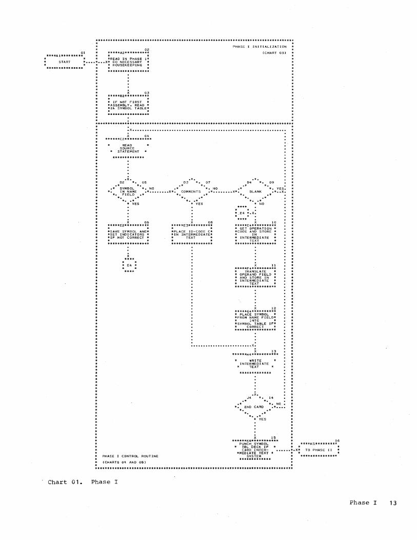
A generalized logic flow of the twophase assembly program is shown on Charts 01 and 02. A detailed description of each phase is given in the "Phase I" and "Phase II" sections of this publication. In the following text, the flowchart block numbers being described are indicated in parentheses.
Phase I (Chart 01)
At the start of the assembly, the Phase I assembly deck or tape is loaded into lower main storage (02).
If the source program is on cards and is being reassembled, the symbol table that was constructed and punched into cards from a previous assembly is read into main storage (03).
The symbolic language source program, on cards or in the form of card images on tape, follows Phase I of the assembly program and the symbol table (if present) • Each source statement from card or tape is read and processed, and the necessary information is punched into the same card, or written onto tape, or punched into a new card before the next source statement is read. If this is a reassembly, the new information is compared to the old informationbefore any action occurs. The type of input depends upon the system configuration.
General Introduction 7

The first test performed on a source statement is to check for a symbol in the name field (OS). If the statement has a symbol in the name field, it is noted (06). The symbol is not placed in the Symbol Table at this time because the correct processing of the symbol will be determined by the operation code of the statement~
Symbols in the name field of some Assembler instructions will not be used by the assembler and,therefore, will not be placed in the Symbol Table.
If the name field does not contain a symbol, but the statement begins with an asterisk (07), indicating -a comments statement, the only action taken is to indicate this in the Intermediate Text (08).
If the statement is blank (09), it is ignored, and the next source statement is read in (04). If it is not blank, the Operation Code Table that was loaded into main storage as part of the assembler decK is searched for the corresponding machine language operation code (10). The machine language operation code is then stored in the Intermediate Text. If the operation code is not found, or if other errors in any part of the source program statement are found by the assembler, the necessary error flag(s) is placed in the Intermediate Text.
The operand field of the source statement is scanned next (11). Formats are checked, and the expressions in the operand field are translated according to format and placed in the Intermediate Text. (See "Phase I," Section 5, "Operand Field Translation. H)
All the information concerning the source statement that can be determined by Phase I is stored in the Intermediate Text, and the Intermediate Text is then punched into a card or written on tape, depending upon the system configuration (13).
The next source statement is then read and processed. Source statements are read and processed until the END statement is encountered (14). When the END statement is encountered, the Symbol Table is punched into blank cards for a card system (15), the value (attribute) section of the Symbol Table is relocated to upper main storage, and the message lEA is printed. The assembly program is then ready to read Phase II into main storage. However, if the assem~
bIer was loaded from tape, the message lEA is not printed, and Phase II is loaded immediately.
8
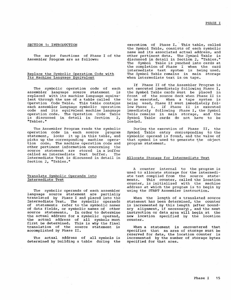
Phase II (Chart 02)
Phase II of the Assembler Program is read into main storage. If the Symbol Table deck is in the card reader, it is read into the area of main storage reserved for the Symbol Table (03).
The first statement containing the Intermediate Text is then read and checked. The output buffer area is checked to determine if enough information has been translated to produce an object program card (07) • If enough information has been translated, an object program card is produced (08) before the next statement is read (05).
The Intermediate according to the type input source statement.
Text and
is translated format of the
An Assembler instruction (09) is translated according to type (14). Each instruction has different requirements and requires a different routine to translate it. (See "Phase II," Section 5, "Intermediate Text Translation.")
A machine instruction (10) must be translated according to format (15) since there are five different formats (RR, RX, RS, SI, SS) f or machine in structions • (See "Phase II," Section 5, "Intermediate Text Translation. ")
If an error was encountered during Phase I requiring that the instruction be assembled as zeros (11), zeros are stored in the output buffer (16).
A statement that contains comments, or an error that will not allow the instruction to be translated, will cause only the source statement to be printed in the object program listing (12).
The Intermediate Text is read and translated until the END statement is encountered (12.5). When the END statement is encountered, the following conditions occur:
1. The remaining information in the output area is produced in object program form.
2. RLD cards, if any, are produced. 3. If object code is being written on
tape, a LDT record is written immediately after the END record and the tape is backspaced. If it is stacked output, only the final LDT record remains, the others being overlaid by the first record of each succeeding job.
4. The message 2EA is printed and the program stops.

r-----------~---------------------------------------------------------------------------,
I 1 I 1 1 I 1 I 1 I
Phase I 11..
r------------, I
Phase I Assembly Program
Temporary Storage**
1------------1 Loader 1 l ____________ J
B. r------------,
Phase I Assembly Program
1 1 1 1 1 I 1 I
------------1 Symbol Table*
1 1 1 1 1 1
1 1 l ____________ J
Phase II A.
r------------, 1 Loader 1 1------------1 1 Phase II 1 1 Assembly 1 1 Program 1 I 1 1------------1 1 Temporary 1 1 Storage** 1 1 1 1 1 1------------1 1 1 1 Symbol 1 1 Table* 1 1 1 l ____________ J
B. r------------,
Phase II Assembly Program
1 1 1 1 1 1 ------------1
Output 1 Buffers 1
------------1 RLD Buffer 1
------------1 Symbol Table*
1 1 1 1 l ____________ J
* Phase I Symbol Table is twice the size of the Phase II Symbol Table. ** Includes housekeeping, ICTL, START, ENTRY, and EXTRN processing. 1
1 _______________________________________________________________________________________ J
Figure 1. Storage Allocation
STORAGE ALLOCATION
Figure 1 illustrates the relative locations in main storage of Phase I and Phase II of the' Assembler Program. Figure 1, part A, shows the allocation at load time, and Figure 1, part B, shows the allocation after the housekeeping and the ICTL, START, ENTRY, and EXTRN processing are completed.
I/O FLOW
Figure 2 illustrates the I/O flow of the Assembler Program.
The Phase I deck is read from the card reader or input tape unit. The Symbol Table deck will then precede the source deck if this is a reassembly procedure as described in the publication, IBM System/360 Basic Programming Support Basic Assembler Language, Form C28-6503.
After the Phase I Assembler deck is read into main storage, and the Symbol Table deck if present, each Statement of the source program is read and partially translated. The partially translated source statement (Intermediate Text) is punched into the source statement car'd (1442), punched into a new card along with the source statement ( 2540), or placed on tape (1442 or 2540 with tape) •
The Phase II deck is then read from the card reader or tape unit. The Symbol Table deck will then be read into main storage if this is a deferred assembly, as described in the publication, IBM System/360 Basic Programming Support Basic Assembler Language, Form C28-6503.
The Intermediate Text developed by Phase I is then read one card or record at a time and translated, the object program is punched into cards or placed on tape, and the object program listing is produced.
Figure 3 shows the buffer areas for the card-only option and Figure 4 shows the buffer areas for the tape option.
General Introduction 9

(1) Reassembly Only (2) Card Option Deferred
Assembly Only
Text
Object Progrom Listing
Card Option
Figure 2. I/O Flow
10
Tape Option

r---------------------------------------------------------------------------------, Card Input
r.-----~A \ r--------------------------------, Phase I I FLDA* I FLDB* I L ________________________________ J
I 24 col. 56 col. I l 80 col. . ) y
Card Output
Card Input (~ _____ ~A \
r---------------------------------------------------, Phase II I FLDC I FLDA I FLDB I L ___________________________________________________ J
t 40 col. J 24 col. l 56 col. ) y y \. y J
FLDA Intermediate Text FLDB Source Statement
Printer Output 96 col. Punch Output 80 col.**
FLDC Object Program Statement
* Punched into source statement card (1442) or new card ( 2540) • ** The 80 col. punch output depends upon the card type. Refer to "Phase II"
I Introduction for card output. I L _________________________________________________________________________________ J
Figure 3. Buffer Areas for Card Option
r---------------------------------------------------------------------------------, I Card Input I I A I I r----------1--------------------------------------, I I Phase I I FLDA I FLDB I I I L _________________________________________________ J I
I I 24 col. I 80 col. I I I \. Y J I I 104 col. Tape Output I I I I Tape Input I I A I I r------------------L----------------------~----------------------i I I Phase II I FLDC I FLDA I FLDB I I I L ________________________________________________________________ J 1
I 1 40 col. 124 col. 1 80 col.* I I 1 \. Y / \. Y / 1 I \.. y / I I 120 col. Printer OUtput 1 1 I I Object program (card or tape) output same as for card only option. I I I I * If ICTL 25, only the last 56 columns of FLDB are printed. 1 I I I FLDA Intermediate Text I I FLDB Source Statement I I FLDC Object Program Statement I L _________________________________________________________________________________ J
Figure 4. Buffer Areas for Tape Option
General Introduction 11

** ** *** ****** * ** ** **** ***** ****** ** ** ** ** *** ***** *** **** ** * * ****** * * ** ** ** **** *** · 02
01 *****A2********** ****Al********* * *
* * *READ IN PHASE 1* START * •••• * ••• X* 00 NECESSARY *
* * * HOUSEKEEPING *************** *
· *
*****************
X 03 *****B2********** . . * IF NOT FIRST * *ASSEMBLY. READ * *If>< SYMBOL TABLE* . . *****************
PHASE I INITIALIZATION
(CHART 03)
• X ••••••••••••••••••••••••••••••••••••••••••••••••••••••• ~ •••••••
Chart 01.
* X 04 * ******C2***********
* · · * · · * * · · * · * * * ·
· · * *
* * * * * *
READ SOURCE
STATEMENT
06 *****E2******** ** * * *SAVE SYMBOL AND* *SET INOI CATORS * *IF NOT CORRECT * * • ********* ********
**** * * * E4 ..
* *
PHASE I CONTROL ROUTINE
(CHARTS 04 AND 05)
Phase I
X 08 *****E3********** . . *PLACE to-CODE C* *IN INTERMEDIATE*
TEXT
*****************
10 *****E4.********** * GET OPERATION * *CODE AND STORE * * IN * * INTERMEDIATE * TEXT * *****************
X 11 *****F 4********** * TRANSLATE * * OPERAND FIELD * * AND STORE IN * * INTERMEDIATE * rEXT * *****************
X 12 *****G4********** * PLACE SYMBOL * *FROM NAME FIELD* * INTO * *SYMBOL TABLE IF* * CORRECT * *****************
· · * ·
* *
* · . . .......................... X.
X 13 ******H4***********
WRITE INTERMEDIATE
* TEXT
.x. J4 *. 14
.* * • • * *. NO • *. END CARD .* ••.•
*. .* *. .* * •• * * YES
X 15
* *
* · * *
* *
******K4*********** 16 PUNCH SYMBOL * ****K5********if
TeL DECK IF * * .. CARD INTER- •••••• *.X* TO PHASE [I
*MEDIATE TEXT * * * SYSTEM ***************
*************
Phase I 13

****Al********* * •
START
X *****B 1 **** ****** . .
01 *****A2********** . .
SET INPUT • •• x* PARAMETERS
* ACCORDING TO * INPUT * *****************
X 02 ******82** * ********
READ IN PHASE II * ••••••
READ A STATEMENT
..
X 03 *****C2*****"*"****
* * *~EAD IN SYMBOL * *T ABLE IF SYMEOL * * T ABLE DECK *
* ********* ********
x 04 *****02********** * SET OUTPUT * *AREAS AND OUT- * *FUT PARAMETERS * * ACCORDI NG TO * * OUTPUT * ********* **** ****
* *
**** * * * C3 * * *
X 05 *****C3**********
* * *RESET NECESSARY* * SW ITCHES AND * *STORE LOC. CTR.* . . *****************
06 ***** *03***********
READ A STATEMENT
PHASE II CONTROL ROUTINE
(CHART 07)
. . ••••••••••••• * ••••••••••• x.
PhASE II INITIALIZATICN
(CHART 06)
Chart 02. Phase II
14
· .x. .*. 14 E3 *. 07 E4 *. 09 *****E5**********
.* IS *. .* *. * * * .* OUTPUT *. NO .* IS IT AN *. YES TRANSLATE * *.BUFFER READY .* •••••••• X*. ASSEMBLER .* •••••••• X* ACCORDING TO * •••• * *. TO BE .* *INSTRUCTION* TYPE '* * *EMPTIED* *..* *
· · * *
· ·
* •• * * •• * **************4** * YES * NO
08 *****F3********** . . * PRODUCE CARD * IF OUTPUT
BUFFER FULL
* • * C3 * * *
.x. 15 F4 *. 10 *****F5**********
.* *. * * .* IS IT A *. YES * TRANSLATE
*. MACHINE .* •••••••• X* ACCORDING TO * •• X. *INSTRUCTION* * FORMAT *
*. .* * •• * *****************
* NO
.x. 16 .*G4 *.*.11 :****G5*********:
.* IS IT TO *. YES * PROCESS * • *.BE ASSEMBLED .* •••••••• X* ERROR * •• X.
*.AS ZEROS .* * *
X 12 *****H4********** * * . 17
*****H5********** • *
* PRINT A LINE *X •••••••• * * *.
.x. J4 *. 12.5
STORE OAT A I N OUTPUT
BUFFER
*. ****J5*********
*x ..... *
.* .* *. YES * * *. END .* •••••••• X* END PHASE II *. .* *
13 *****K4********** * •
INCREMENT LOCATION
COUNTER
. . * C3 * . .
SECTION 1: INTRODUCTION
The major functions of Phase I of the Assembler Program are as follows:
Replace the Symbolic Operation Code with Its Machine Language Eguivalent
The symbolic operation code of each assembler language source statement is replaced with its machine language equivalent through the use of a table called the Operation Code Table. This table contains each assembler language symbolic operation code and its equivalent machine language operation code. The Operation Code Table is discussed in detail in Section 2, "Tables."
The Assembler Program reads the symbolic operation code in each source program statement, looks it up in this table, and picks up the corresponding machine operation code. The machine operation code and other pertinent information concerning the source statement are stored in a buffer called an Intermediate Text buffer. The Intermediate Text is discussed in detail in Section 2, "Tables."
Translate Symbolic Operands into Intermediate Text
The symbolic operands of each assembler language source statement are partially translated by Phase I and placed into the Intermediate Text. The symbolic operands of statements refer to the symbolic names of data fields, or symbolic names of other source statements. In order to determine the actual address for a symbolic operand, the actual address of all symbols must first be determined. This is why the final translation of the source statement is accomplished by Phase II.
The actual address of all symbols is determined by building a table during the
PHASE I
execution of Phase I. This table, called the Symbol Table, consists of each symbolic name and its associated actual address, and other pertinent data. The Symbol Table is discussed in detail in Section 2, "Tables." The Symbol Table is punched into cards at the completion of Phase I when the card intermediate text system is being used. The Symbol Table remains in main storage when intermediate text is-on tape.
If Phase II of the Assembler Program is not executed immediately following Phase I, the Symbol Table cards must be placed in front of the source deck when Phase II is to be executed. When a tape system is being used, Phase II must immediately follow Phase I. If Phase II is executed immediately following Phase I, the Symbol Table remains in main storage, and the Symbol Table cards do not have to be load,ed.
During the execution of Phase II, the Symbol Table entry corresponding to the symbolic operand is found, and the value of that symbol is used to generate the object program statement. .
Allocate Storage for Intermediate Text
A counter internal to the program is used to allocate storage for the intermediate text compiled from the source statements. This counter, called the location counter, is initialized with the machine address at which the program is to begin by using the START Assembler instruction.
When the length of a translated source statement has been determined, the counter is incremented by this length (after boundary alignment, if necessar~ , and the next instruction or data area will begin at the new location specified by the location counter.
When a statement is encountered that specifies that an area of storage must be reserved for data, the location counter is incremented by the number of storage bytes specified for that area.
Phase I 15

SECTION 2: TABLES
INTERMEDIATE TEXT
The Intermediate Text associated with each statement contains a total of 24 bytes of information. The specific meaning of the 24 bytes of information and the bit patterns associated with the bytes are shown in a figure accompanying the description of each instruction type in Section 5, ·Operand Field Translation." A general discussion of the bytes in the Intermediate Text is given in this section.
Figure 5 is a summary of the Intermediate Text associated with each instruction type.
The breakdown of the Intermediate Text is as follows:
Byte 1 - ID-Code
This field is one byte in length and contains an ID-Code which indicates whether the source statement is a machine instruction or an Assembler instruction, whether the instruction contains an error, and whether or not the statement requires further processing by Phase II. The possible ID-Codes and their meanings are as follows:
r-----T-----------------------------------, ICode I Meaning I ~-----+-----------------------------------i
A Machine instruction, no errors I I
B Assembler instruction, no errors 1
C Comments * J Error in a machine instruction
statement
K Error in an Assembler instruction statement
L Error, statement not assembled*
M Error, operand field assembled as zeros
~----....:J.-----------------------------------i I * Error flags printed but no further I I translation by Phase II I L _________________________________________ J
After it is determined whether the operation code is a machine instruction, an
16
Assembler instruction, or a comments statement, an ID-Code of A, B, or C, respectively, is placed into byte 1 of the Intermediate Text. If an error is encountered later during the translation of the source statement, these ID-Codes will be replaced with the appropriate error ID-Code (i.e., J,K,L, or M) •
Byte 2 - Operation Code
The machine-language operation code is placed ~n this field after the search of the Operation Code Table. This field will be blank if the source statement contains an illegal operation code.
Bytes 3-22 - Operand Field
These bytes contain the text compiled from the operand field of the instruction. Since these bytes will contain different information for each instruction type, they are explained in detail in the discussion of each instruction in Section 5, "Operand Field Translation." Bytes 21 and 22 may contain error flags if the error ID-Code is L or M.
Bytes 21-24 - Error Flags
These bytes will contain error flags to indicate the type of error encountered during the translation of the instruction. If no error is encountered, the bytes will be blank. The error flags and their meanings are shown .in Phase I, Section 3, "Subroutine Description," under the discussion of subroutine ERR.
OPERATION CODE TABLE
The Operation Code Table is divided into five sections, each section containing all the symbolic codes of the same length (e.g., all one-character symbolic codes in
one section, all two-character symbolic codes in another section, etc.) plus the equivalent machine-language code. All symbolic codes within each section are also grouped according to the operand field format (e.g., all machine instructions in the 51 Format; SS Format, etc.)

--------------T-----------------------------------------------------------------------, Byte I I I I I I I I I I I I I I I I I I I I I I I I I
11121 3 1 4 1 5 1 6 1 7181 91101111121131141151161171181191201211221231241 I Instructio I 1 1 I I I I I I I I I I I I 1 I I I I I I I I I ~--------------- --------------------~--------------------------------------------------i I RR 1 A I OP I R2 I R 1 I I ~---------------+-----------------------------------------------------------------------~ 1 RX I A I OP I X2 I R 1 I D 2 I B2 I I ~---------------+---------------------------------..,..-----------------------------------~. I RS I A lOP I R3 I R 1 I D2 I B2 I I ~---------------t-----------------------------------------------------------------------~ I S I I AI OP 1 liD 1 I B 1 I I ~---------------t-----------------------------------------------------------------------~ I SS I A lOP I LUL I L 1 I D 1 I B 1 I D2 I B2 I I ~---------------t-----~---------~-------------------------------------------------------~ I CNOP I B I E3 1 I ba I d 1 I d2 I , I ~---------------+----~------------------------------------------------------------------~ I ICTL I BIEDI d I I ~---------------+-----------------------------------------------------------------------~ I EJECT I BlEB I I .---------------+-------------------~---------------------------------------------------~ I SPACE I B I E71 d I I ~---------------+-----------------------------------------------------------~-----------~
~ I ORG I B I E8 I I rx I I .---------------+-----------------------------------------------------------------------~ lEND I BIEFI I rx or blank I I ~---------------+-----------------------------------------------------------------------~ I EQU I B I E5 1 I ax or rx I I ~---------------+---------------------------------------------------------------------~ I USING I BIE61 I rx I sx I I ~---------------+-----------------------------------------------------------------------~ I DROP I B I EC t I sx I . I ~---------------+--------------------------~------------------------------------------~~ I EXTRN I B I E91 1 rs I as I I ~---------------+-----------------------------------------------------------------------~ I ENTRY I BIEAI I ,rs I as I I .---------------+-----------------------------------------------------------------------~ I START I BI EEl I bal aa I as I I ~---------------+-----------------------------------------------------------------------~ I CCW I B I E4 I sx I rx I sx I sx I I .---------------+-----------------------------------------------------------------------~ IDS I BIEOI llbal d I I ~---------------+-----~-----------~-----------------------------------------------------~ IDC(C,D,E,F,H,~ I BIE11 llbal m I dc I I .---------------+-----------------------------------------------------------------------.~ I DC (A) I B I E2 I 11 ba I m I I ax or rx I I .---------------+-----------------------------------------------------------------------~ I COMMENTS I CI ' I ~---------------+-----------------------------------------------------------------------~ I Err.Mach.Instr.I JIOPI same as Type A . le.f. I
.---------------+-----------------------------------------------------------------------1 I Err.Assem.Inst.I KIOPI same as Type B le.f. I .---------------+-----------------------------------------------------------------------1 I ERR (1) _ I L I I error flags I ~---------------+---------------------------------------------------------------------~ IERR (2) I MIOPI nl lerror flags.1 .---------------~-----------------------------------------------------------------------1 I Legend I I aa = assembled address d = decimal integer n = number of bytes of I I as = actual symbol dc = defined constant zeros to be assembled I I ax = absolute expression e.f. = error flags rs = relocatable symbol I I ba = boundary alignment bits 1 = length of constant rx = relocatable expression I t m = duplication factor sx = simple expression I
.---------------------------------------------------------------------------------------i I (1) statement not assembled (2) operand assembled as zeros I L ___________________________________________________________________________________ ~_~J
Figure 5. Intermediate Text Summary
Phase I 17

The organization of this table allows a faster assembly because it is not necessary to search the entire table to find the equivalent machine-language code. Only the section of the table containing the same number of characters as the symbolic code is searched. In addition, the table provides the Assembler Program with the operand field format and the address of the subroutine necessary to translate that format.
The machine-language operation code obtained from the table is placed into the Intermediate Text.
The Operation Code Table is loaded into main storage as part of Phase I.
SYMBOL TABLE
The Symbol Table is divided into two sections. The first section contains the compressed symbols from the source statements; the second section contains the attributes (values) associated with each symbol. Only the attributes are passed on to Phase II because there is no further need of the symbol itself once it has been replaced with the address of the location within the Symbol Table that contains the symbol attributes.
The first two entries in the Symbol Table refer to the location counter. The first entry contains the current setting of the location counter. This entry is necessary because the current setting of the location counter can be referred to within the symbolic program with an asterisk. For example, the expression (*+12) in the operand field of a symbolic statement refers to the current location plus 12 bytes. Therefore, when an asterisk is encountered as a symbol, the Assembler Program replaces the asterisk with the address contained in the first entry of the Symbol Table.
The second entry contains the highest value the location counter reached during Phase I. This location is needed for the producing of an External Symbol Dictionary (ESD) START card, which is used by the relocatable loader. This is a function of Phase II and is discussed in detail in the introduction to Phase II.
The format of the Symbol Table Cards produced by Phase I is shown in Figure 6.
The attributes assigned toa symbol when the symbol is defined in the Symbol Table are as follows:
18
Location
This is a two-byte field cqntaining the machine address of the symbol.
Length
This is a one-byte field containing the number of storage bytes associated with the symbol. This number will always be one less than the actual number due to programming considerations. For example, if the symbol DATA is the name of the DS instruction that defines a data area of 16 bytes, DATA would have a length of 15 assigned to it in the Symbol Table. When a length is not indicated, the Assembler Program assumes a length of one byte.
If the symbol is defined by a compound expression, the length is the same as the implied length of the leftmost simple expression in the compound expression. If the leftmost expression is a self-defining value, the length attribute is one.
Relocatability
This four-bit (1/2 byte) field contains a 1 - 15 if the symbol is relocatable and a zero if the symbol is not relocatable (i.e., is assigned an absolute address).
If the symbol is a linkage symbol that has been defined in the operand field of an EXTRN instruction, the relocatability field will contain a value from 2 to 15, depending upon which EXTRN instruction in the source program defines the symbol. For example, if the symbol was defined by the first EXTRN instruction, the relocatability value would be 2. If it was defined by the second EXTRNinstruction, the relocatability value would be 3, etc. If the symbol is defined in the same program and not in the operand field of an EXTRN instruction, the relocatability attribute will be one.
Defined Bit
Each Symbol Table entry also contains one bit to indicate whether or not the symbol was ever defined.

r---------------------------------------------------------------------------------------, r---------------------------------------------------------------------------------, I 11 2 3 4 I 5-16 1 17-28 I 29-40 I 41-52 I 53-64 1 65-76 177 - 801 1---------------------------------------------------------------------------------1 1121 Address of 1 1 1 1 1 1 1 I I 9 1 first loco 1 * 1 * 1 * 1 * I * 1 * I Blank I 1 410f Phase II 1 1 1 I I I 1 I 1 ISymbol Table 1 1 I I 1 1 1 I l ___________________________________________________________ ~---------------------J
I I I I I 1 1 1 1 1 * Each of these 12 bytes conta1ns the symbol name, value, and attributes as follows: 1
Byte 1-2 3-4 5-8 9-10 11 12
Contents Pointer to symbol position in table Not used Symbol in compressed form Symbol value Symbol length Symbol attributes
bits 0-3 relocatability bit 4 defined bit
1 = defined o = undefined
bit 5 1 = entry used
1
o = not an entry or entry not defined. __________________________________________________ ~ ____________________________________ J
Figure 6. Symbol Table Card Format
Phase I 19

SECTION 3: SUBROUTINE DESCRIPTION
This section describes the subroutines of the Assembler Program that are used during Phase I processing.
EVE - Evaluation Routine (Charts AM and AN)
This subroutine is used during Phase I of the Assembler Program to accomplish the following:
1. Scan the Name Field 2. Scan for non-blank character 3. Scan the Operation Code Field 4. Translate the Operand Field
The first three items mentioned above are discussed in detail in Section 4, "Phase I Processing Flow," under "Control Routine." Only the translation of the operand field will be discussed here. However, the parameters necessary for each of the above procedures are shown at the end of this discussion.
This subroutine is shown in detail in Charts AM and AN.
Subroutine EVE will scan the operand field until the first character of the operand field expression is located. Subroutine EVE then translates the first term of the operand field expression and compares the translation to the parameters described below. The translated results, if correct, are placed into the relevant bytes of the Intermediate Text by subroutine STORE.
If the translation is not correct, control exits from this subroutine via the error exit set up by the calling routine.
After the translated term is placed into the Intermediate Text, control exits to the calling routine. The calling routine then determines if the character following the term is correct. If it is correct, and more terms of the operand field need translation, new parameters are set up and subroutine EVE is entered again.
The parameters used by subroutine EVE, which describe the next term of the expression in the operand field to be translated, are as follows:
T is set according to the type of term to be translated as follows:
20
L
o operand should be blank 1 = a simple term 2 = a compound term 3 an integer (decimal value)
indicates the number of bytes of intermediate text the term being translated will occupy.
M indicates the maximum value allowed for any self-defining value within the expression being translated.
PC indicates the starting column minus 2 (due to programming considerations) of
the Intermediate Text into which the translated term of the expression will be placed.
C indicates the operation code of the statement being translated or the operation to be performed by subroutine EVE, as follows:
10 20 = 20 40 60 =
CNOP EXTRN ENTRY Name Field or Operation Code scan DS or DC (type C,D,E,F,H,X), EJECT, SPACE, or scan until non-
80 90 AO BO
blank character = END
00
= ORG or EQU START DC (type A), USING, DROP, or CCW (2nd term) all other operation codes
The other subroutines used by subroutine EVE are:
DCC - Define Character Constant: This subroutine is used when a character constant appears in the operand field of a source statement. It translates the character constant and checks its validity.
DCF Define Full-Word Constant: This SUbroutine is used when a full-word constant appears in the operand field of a source statement. It converts a decimal integer to its binary representation and checks its validity.
DCX - Define Hexadecimal Constant: This SUbroutine is used when a hexadecimal constant appears in the operand field of a source statement. It translates the hexadecimal constant and checks its validity.
TLUS - Symbol Table Look-up: This subroutine is used when a symbol appears in the operand field of a source statement. It looks up the symbol in the Symbol Table and indicates its value (if known), its location in the Symbol Table, its length and relocatability attributes, and the bit

indicating whether or not the symbol is defined.
STORE - Store into Intermediate Text: This subroutine stores the translated terms of the expression in the operand field into the Intermediate Text.
ERR - Store Error Flags
The ERR subroutine places the necessary error flags into the Intermediate Text. If the error is such that the statement can not be assembled by Phase II, ID-Code L is also placed into the Intermediate Text. This subroutine is entered from the calling routine at location ERR if it is necessary to place the ID-Code into the Intermediate Text along with the error flags. If only the error flags are to be placed into the Intermediate Text, this subroutine is entered at location ERR1. The error flags are dependent upon the error conditions and are set by the calling routine.
The' error flags that may be placed into the Intermediate Text by Phase I are shown in Figure 7.
Figure 8 shows what action is taken in Phase I of the Assembler Program when errors are encountered in the source statement.
BAR - Boundary Alignment Routine
The BAR subroutine is used to align the location counter to the proper word boundary, if necessary.
This subroutine will interrogate the boundary alignment bits of the InteEmediate Text (byte 4) and, if necessary, add to the location counter the number of bytes that will align it to the proper word boundary.
After the location counter is incremented, it is tested to see if it exceeds the maximum allowable value of 65,535. If it does, the location counter is truncated and an error flag is placed into the Intermediate Text.
r-----T-----------------------------------, 'Flag , Meaning , ~-----+-----------------------------------~ * A 'Expression not simply relocatable
*
, B ,START, EXTRN, ENTRY, or ICTL out
, of order , C ,Location counter overflow
I E ,More than 14 EXTRNs or more than
I 100 ENTRIES I
F ,
G
J
L
M
N
0
Operand field format self-defining value in field too large
DC D or E range error
Symbol Table full
Name field error
Multiple defined symbol
Statement not used
Invalid operation code
error or operand
* R Expression not absolute
* S Specification error I , * T Value too large ,
I V ORG orEQU symbol not previously'
defined I I
* Y Negative expression I I
Z I Column 72 not blank I t-----~-----------------------------------~ 1* May also be set by Phase II. I l _________________________________________ J
Figure 7. Error Flags
STORE - Store into Intermediate Text
The STORE subroutine is used to store the translated expressions of the operand field into the Intermediate Text.
This subroutine will store, one byte at a time, the translated terms of the expression in the operand field into the correct bytes of the Intermediate Text. The correct byte is determined by adding the value of the input parameter PC, which is set to the starting byte (minus 2) into which the translated term is to be placed, to the length of the translated term.
Therefore, the translated into the Intermediate Text the low-order byte of the Intermediate Text associated
term is placed beginning with field of the with the term.
Phase I 21

r------------------T-------------------------T------------------------------------------, I I I I I INSTRUCTION I NAME FIELD ERROR I OPERAND FIELD ERROR I I I (Error Flag Set For All Instructions) I ~------------------+-------------------------T------------------------------------------~ I All Machine I Symbol stored I Indicate how many bytes of zeros I I Instructions I in Symbol Table I are to be assembled by Phase II I I I I for the operand field I ~------------------+--------------~----------+----~-------------------------------------~ I CCW I Symbol not stored I Indicate how many bytes of zeros I I I in Symbol Table I are to be assembled by Phase II I I I I for the operand field I ~------------------+-------------------------+------------------------------------------~ I CNOP I Symbol ignored I Statement ignored I ~------------------+----~---------~----------+---------------------------------------~--~ I DC I Symbol not stored I Statement ignored I I I in Symbol Table I Undef ined symbol in type A will I I I I set operand field to zero I ~------------------+-------------------------+------------------------------------------~ I DROP I Symbol ignored I Statement ignored I ~------------------+-------------------------+------------------------------------------~ I DS I Symbol not stored I Statement ignored I I I in Symbol Table I I ~------------------+--------~----------------+------------------------------------------~ I EJECT I Symbol ignored I Symbol ignored I ~------------------+-------------------------+------------------------------------------~ I END I Symbol ignored I No ENTRY point to this program I I I I will be defined I ~------------------+-------------------------+------------------------------------------~ I ENTRY I Symbol ignored I Statement ignored I ~------------------+-------------------------+------------------------------------------~ I EQU I Statement ignored I Statement ignored I ~------------------+-------------------------+------------------------------------------~ I EXTRN I Symbol ignored I Statement ignored I ~------------------+-------------------------+------------------------------------------~ I ICTL I Symbol ignored I Operand set to a 1 in a tape system I I I I and to 25 in a card system I ~------------------+-------------------------+------------------------------------------~ I ORG I Symbol ignored I Statement ignored I ~----~-------------+-------------------------+------------------------------------------~ I SPACE I Symbol ignored I If not a decimal value, statement I I I I ignored I ~------------------+-------------------------+------------------------------------------~ I START I Symbol not stored I Location counter set to zero I I I in Symbol Table I I ~------------------+-------------------------+------------------------------------------~ I USING I Symbol ignored I Statement ignored I L __________________ ~ _________________________ ~ __________________________________________ J
Figure 8. Error Summary
BUMP - Increment Location Counter
The BUMP subroutine is used to increment the location counter by the required number of bytes and to indicate if the location counter exceeds the maximum allowable value of 65,535.
After the source statement is translated and placed into the Intermediate Text, the location counter is incremented by the number of bytes determined by the operation code of the statement. The location counter is incremented (after boundary alignment) as shown in Figure 9.
22
This subroutine is entered with the parameter VALUE indicating the amount the location counter is to be incremented by or reset to. It is entered with parameter ADJUST BIT set to a zero if the location counter is to be incremented; parameter ADJUST BIT set to a one if the location counter is to be reset.
After the location counter is incremented or reset, it is tested to see if it exceeds the maximum allowable value. If it does, the location counter is truncated and an error flag is placed into the Int-ermediate Text.
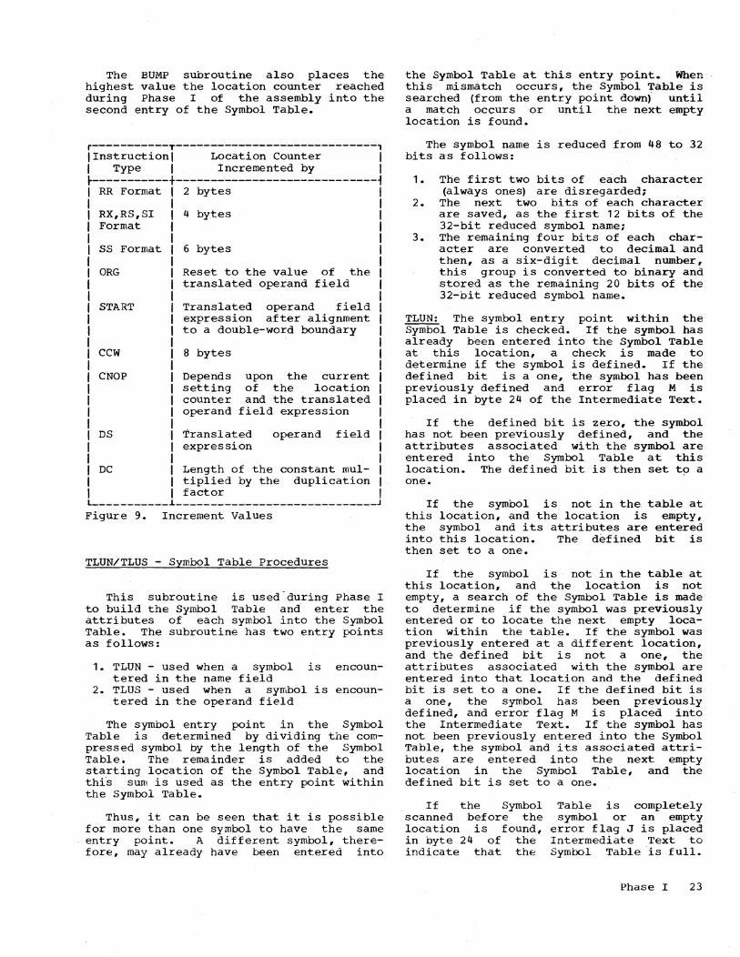
The BUMP sUbroutine also places the highest value the location counter reached during Phase I of the assembly into the second entry of the Symbol Table.
r-----------T-----------------------------, I Instruction I Location Counter I I Type I Incremented by I ~-------~---+-----------------------------i
RR Format 2 bytes I
RX,RS, SI Format
SS Format
4 bytes
6 bytes
I I I I I I
ORG Reset to the value of the I translated operand field I
START
CCW
CNOP
DS
Translated operand field expression after alignment to a double-word boundary
8 bytes
Depends setting counter operand
upon the current of the location and the translated
field expression
Translated expression
operand field
DC Length of the constant multiplied by the duplication factor L-__________ ~ ____________________________ _
Figure 9. Increment Values
TLUN/TLUS - Symbol Table Procedures
I I I
This subroutine is used-during Phase I to build the Symbol Table and enter the attributes of each symbol into the Symbol Table. The subroutine has two entry points as follows:
1. TLUN - used when a symbol is tered in the name field
2. TLUS - used when a symbol is tered in the operand field
encoun-
encoun-
The symbol entry point in the Symbol Table is -'determined by dividing the compressed symbol by the length of the Symbol Table. The remainder is added to the starting location of the Symbol Table, and thi's sum is used as the entry point within the Symbol Table.
Thus, it can be seen that it is possible for more than one symbol to have the same entry point. A different symbol, therefore, may already have been entered into
the Symbol Table at this entry point. When this mismatch occurs, the Symbol Table is searched (from the entry point down) until a match occurs or until the next empty location is found.
The symbol name is reduced from 48 to 32 bits a-s follows:
1. The first two bits of each character (always ones) are disregarded;
2. The next two bits of each character are saved, as the first 12 bits of the 32-bit reduced symbol name;
3. The remaining four bits of each character are converted to decimal and then, as a six-digit decimal number, this group is converted to binary and stored as the remaining 20 bits of the 32-bit reduced symbol name.
TLUN: The symbol entry point within the Symbol Table is checked. If the symbol has already been entered into the Symbol Table at this location, a check is made to determine if the symbol is defined. If the defined bit is a one, the symbol has been previously defined and error flag M is placed in byte 24 of the Intermediate Text.
If the defined bit is zero, the symbol has not been previously defined, and the attributes associated with the symbol are entered into the Symbol Table at this location. The defined bit is then set t9 a one.
If the symbol is not in the table at this location, and the location is empty, the symbol and its attributes are entered into this location. The defined bit is then set to a one.
If the symbol is not in the table at this location, and the location is not empty, a search of the Symbol Table is made to determine if the symbol was previously entered or to locate the next empty location within the table. If the symbol was previously entered at a different location, and the defined bit is not a one, the attributes associated with the symbol are entered into that location and the defined bit is set to a one. If the defined bit is a one, the symbol has been previously defined, and error flag M is placed into the Intermediate Text. If the symbol has not been previously entered into the Symbol Table, the symbol and its associated attributes are entered into the next empty location in the Symbol Table, and the defined bit is set to a one.
If the Symbol scanned before the location is found, in byte 24 of the indicate that the
Table is completely symbol or an empty
error flag J is placed Intermediate Text to Symbol Table is full.
Phase I 23

This symbol, and any other symbol following that is not already entered into the Symbol Table, will remain undefined.
TLUS: The symbol entry pOint within the Symbol Table is checked. If the symbol has already been entered into the Symbol Table at this location, a pointer to this location is placed into the relevant bytes of the Intermediate Text.
If the symbol is not in the table at this location, and the location is empty, the symbol is entered into this location. Since the symbol is from the operand field, none of the symbol attributes are known at this time. Therefore, the remainder of the table entry for this symbol remains blank. The attributes for the symbol will be placed into the Symbol Table when the symbol is encountered in the name field of a source statement. A pointer to this location is then placed into the relevant bytes of the Intermediate Text.
If the symbol is not in the table at this location, and the location is not empty, a search of the Symbol Table is made to determine if the symbol was previously entered or to locate the next empty location within the Symbol Table. If the symbol was previously entered at a different location, a pointer to that location is placed into the relevant bytes of the Intermediate Text. If the symbol has not been previously entered into the Symbol Table, the symbol is entered into the next empty location in the Symbol Table, and a pOinter to that location is placed into the relevant bytes of the Intermediate Text.
If the Symbol Table is completely scanned before the symbol or an empty location is founq, error flag J is placed in byte 24 of the Intermediate Text.
INOUT - Input/Output Subroutine (CHARTS AO and AP)
This subroutine is the same for both Phase I and Phase II. It controls all the I/O operations for the Assembler Program.
The sUbroutine is entered at location INOUT from the calling routine. The interrupts are disabled and the CAW and device address are stored (02-04).
The I/O device following cohditions
is then tested for the (05) :
1. Device unavailable. This is an error condition and an error halt occurs. The SEREP ID code for the unavailable device is set and the device address
24
is stored in the old IOPSW (bytes 2 and 3) •
2. Device busy. The program goes into an internal loop until the device is ready. When the device is ready, a test is made to determine if the CSW is stored.
3. CSW stored. Control is transferred to the interrupt routine.
The condition codes and their meanings are as follows:
Condition code o 1
2 3
Meaning Available CSW stored (Immediate operation)
Busy Unavailable
When the device is available and ready, an attempt is made to start the I/O operation. Two procedures are possible as follows:
1. The device is started and the data transfer initiated. Interrupts are enabled, and the program enters a wait state until an interrupt occurs (06-07). When an interrupt occurs, either as a result of the current SIO or from a previous SIO, the interrupt procedure is initiated. The interrupt entry switch is set (except when a busy condition was cleared by a TIO operation), and a Retry switch is tested (09-10).
2. The device is started for an immediate operation (rewind, skip), the interrupt procedure I is initiated, and the Retry switch is tested.
The Retry switch is. tested and if this a tape-positioning operation (backspace, skip) or sensing operation resulting from the error correction procedure, control is transferred to the error correction procedure.
If the Retry switch is not on, the read switch is set if this is a read operation, and the error condi tions ar.e checked (11-12). If it is a channel error, the
SEREP ID code and the recovery address in the external New PSW are set and the program enters a wait state with AIS in the location counter (13-33-28). If it is a unit error and the unit is not tape, the SEREP ID code for device failure is set, the recovery address is set in the external New PSW, and the program enters a wait state with AIS in the location counter (14-34-28). If there is a unit error, and

the unit is tape, control is transferred to the error correction procedure (AP-A2).
If there are no errors, the busy indicator is checked (15). If the busy indicator is on, control is transferred to the interrupt procedure to check the Retry switch.
If the error switch was set on this pass, it is cleared and the registers restored before EOF and other exceptional conditions are checked.
If there are no exceptional conditions, control is returned to the calling routine. If an exceptional condition is caused QY the printer, it is ignored, arid contI:0l is returned to the calling routine; otherwise the error halt occurs and the recovery address is placed in the external New PSW (32) •
Error Recovery Procedure: is entered for a tape
This procedure error only. The
Retry CSW, bytes tions
switch is set and the I/O OldPSW, and CAW are' saved (01). The sense are requested and the original condiare restored (02-04).
If the sense information is a unit check, a test is made to determine if it is a first read error (05-06). If it is, the error switch is turned on. If it is not a first error, the read switch is checked and 10 read retries are made. If the read attempt is still not successful, an error halt occurs and a standard device failure message is produced.
If it is a write failure, three rewrite and skip operations occur three times before an error halt occurs and a standard device failure message is produced.
Note: The error recovery procedure described above does not conform to IBM standards; i.e., no priority checking or tape cleaning is implemented.
Phase I 25

SECTION 4: PHASE I PROCESSING FLOW
This section uses three charts to describe the overall processing flow of Phase I of the Assembler Program. Chart 03 illustrates the initialization procedures, and Charts 04 and 05 illustrate the Control Routine. The numbers in parentheses within the text describing each chart indicate the block on the chart being explained.
INITIALIZATIOl - CHART 03
Phase I of the Assembler Program is read into main storage (01). Th~ addressability and main storage size, as determined by the Phase I Configuration Card, are set up, and the necessary control parameters to be used by the subroutines of Phase I are generated and stored (02-03).
The Configuration Card is discussed in detail in the publication, IBM System/360 Basic programming Support Operating Guide for Basic Assembler and Utilities, Form C28-6557.
The area reserved for the Symbol Table, determined by the size of main storage, is cleared, and the first two entries are reserved for the uses indicated in Section 2, "Tables" (04).
The input/output addresses are determined and set up for the read and write routines. These addresses are determined by the intermediate text device being used (card or tape). The size of the Intermedi-ate Text to be written or punched as output (24 bytes for a card intermediate text system, 104 bytes for a tape intermediate text system) is stored into the necessary locations of the write routine (05-12). The first source statement is then read in (13) •
In a card intermediate text system, if column 1 of the first card indicates it is a Symbol Table card (14), the Symbol Table deck is read into the area of main storage reserved for the Symbol Table (15). The use of the Symbol Table deck is discussed in detail in the publication, IBM System/360 Basic programming Support Basic Assembler Language, Form C28-6503.
After the last card of the Symbol Table deck is read into main storage, or when the Symbol Table deck is not present, control exits to the Phase I Control Routine (Chart 04) •
26
CONTROL ROUTINE - CHART 04
The first statement of th~ source program is read in (01). The first column of the card to be scanned by the EVE subroutine (determined by the SYSCON control byte of the Phase I Configuration Card) is set, the control switches are set, and the punch buffer output area is cleared (02).
Column 72 of the source program statement, which must be blank, is tested (03). If it does not contain a blank, error flag Z is placed in byte 22 of the relevant Intermediate Text (04). .Any information contained in column 72 is ignored when the source statement is processed, but column 12 is printed as part of the source statement in the program listing.
The first column of the source statement is tested for an asterisk or a blank (05-06) • If the source statement begins
with a blank, the operation code is then checked (11). If the column contains an asterisk, IO-Code C, indicating the source card is a comments card, is placed in byte 1 of the Intermediate Text. No further translation of the source statement is performed during the assembly process. A comments card is only reproduced in the object program listing.
If the statement begins with neither an asterisk nor a blank, it indicates that the source statement begins with a symbol in the name field. The symbol in the name field is scanned by subroutine EVE to determine if i.t is valid (08). If the symbol is valid (i.e., begins with an alphabetic character and contains no more than six characters), the valid-symbol indicator is set. However, the symbol is not placed into the SYmbol Table at this time. A symbol in the name field of the source statement being translated may not be allowed. Until this can be determined, the symbol is only temporarily stored (09). If the symbol is not valid, error flag L is placed in byte 24 of the Intermediate Text (10) • The operation code is then checked (11) •
If the ·operation code field of the source statement is blank (the remainqer of the source statement is blan~ IO-Code L, indicating the statement is not to be assembled as part of the object program, and error flags NO are placed in bytes 1, 23, and 24, respectively, of the Intermediate Text (17). If the remainder of the source statement is not blank, but the operation code has been omitted, the first characters of the operand field or comments field will be treated as the operation code. Control then exits to produce the Intermediate Text (Chart 05, block F2) •

If the operation code field contains an operation code, the Operation Code Table is searched to determine if the operation code is valid (12). If the operation code is not valid, ID-Code L, indicating the statement is not to be assembled as part of the object program, and error flags Nand 0 are placed in bytes 1, 23, and 24, respectively, of the Intermediate Text (17). The next source program statement is then read in (01).
If the operation code contained in the source statement is found during the search of the Operation Code Table, it is checked for type (14). If it is a machine operation code, ID-Code A is placed in byte 1 of the Intermediate Text, and the location counter is aligned to a half-word boundary (18-19). Control then exits to the, subrou-t~ne necessary to translate the operand field as determined by the operation code.
If the operation code indicates an Assembler Instruction, ID-Code B is placed in byte 1 of the Intermediate Text and control exits to the subroutine necessary to translate the operand field as determined by the operation code. (See Section 5, "Operand Field Translation. ")
Subroutine EVE is used to translate the operand field of each statement. The translation of each operand field by subroutine EVE is basically the same regardless of the type of statement. This subroutine is, however, entered with different parameters for each statement type. These parameters are shown in the description of subroutine EVE in Section 3, "Subroutine Description. "
Each expression within the operand field is translated separately and placed in the relevant bytes of the Intermediate Text for that statement.
If an error is encountered in the operand field, the remaining expressions within the operand field are not translated. The intermediate text that has been developed up to that pOint, however, is written as Intermediate Text with the relevant ID-Code and error flags. The ID-Codes used in the Intermediate Text are discussed in the description of the Intermediate Text in Section 2, "Tables." The error flags and their meanings are shown in Section 3, "Subroutine Description," under subroutine ERR. These flags are also shown in Figure 3.
If an error is encountered during the translation of the operand field such that the statement will not be assembled by Phase II (20), control exits to produce the Intermediate Text ~hart OS, block F2). If
not, control exits to Chart OS, block B2, to process the name field.
CONTROL ROUTINE - CHART 05
The valid-name indicator (set if the symbol in the name field was valid) and the name-allowed indicator (set by the operand translation subroutine if a symbol in the name field of the source statement being translated is legal) are tested (01).
If neither indicator is set, byte 24 of the Intermediate Text is tested to determine if an invalid symbol (error flag L) was in the name field (OS). If byte 24 is blank, control transfers to produce the Intermediate Text (09). If byte 24 contains error flag L, the ID-Code indicating an error is placed in byte 1 of the Intermediate Text , replacing the ID-Code already there (04). Control then transfers to produce the Intermediate Text (09).
If one indicator is set, the valid-name indicator is checked (02). If the validname indicator is not set, the procedures described above for neither indicator set are followed (05). If the valid-name indicator is set but not the name-allowed indicator, the ID-Code indicating an error is placed in byte 1 of the Intermediate Text replacing the ID-Code already there (04). It is possible that the symbol in
the name field of this source statement is referenced in the operand field of another source statement. If this is the case, the source statement referencing this symool will contain an error flag, indicating an undefined symbol because this symbol is not placed into the Symbol Table. Flagging both statements will make the error easier to locate. Control then transfers to produce the Intermediate Text (09).
If both indicators are set, indica'ting there' is a valid symbol in the name field and a name is allowed for the source statement being translated, the value of the location counter is placed into the value attribute of the symbol in the Symbol Table (06).
If an error is encountered by subroutine TLUN while placing the symbol into the Symbol Table (e.g., Symbol Table is full), the ID-Code indicating an error is placed in byte 1 of the Intermediate Text along with the error flag placed by subroutine TLUN, replacing the ID-Code already there. Control then, tran~fers to produce the Intermediate Text (09).
If no error is encountered by subroutine TLUN (08), control transfers to produce the Intermediate Text (09).
Phase I 27

Depending upon the configuration of the system being used to assemble the program, one of the following three procedures, along with the common procedure, is followed.
Tape Procedure (blocks 09, 12-14): The Intermediate Text is written on tape.
1442 Card Read Punch Procedure (blocks 10, 14, 20-21): If the information in the first 24 columns of the SOUrce card is equal to the information in the Intermediate Text (10), this is a reassembly, and the pURching of the Intermediate Text is not necessary since the source card already contains the record for that statement. Control then transfers to test for an END card (15).
If the information is not equal the first 24 columns of the source blank (20) , the Intermediate punched into these columns (14).
(10) and card are Text is
If the information is not equal (10) or the first 24 columns of the source card are not blank (20), the punch buffer is blanked and a '9' is placed into column 1 of the Intermediate Text. If the system has a printer or typewriter, the '9' is ~unched into the card, and error flag N will be printed in the listing produced by Phase II. If no printer or typewriter is available, the system stops. A manual interrupt will cause processing to be resumed; the '9' is punched into column 1 of the card (14), and processing continues.
28
2540 Card Read Punch Procedure (blocks 09, 12-14: The Intermediate Text is moved to the output area, if necessary, and punched into the first 24 columns of a blank card. Then the first 48 columns, the Identification-Sequence Field, and column 72 of the source card are punched into the remaining columns of the new card.
Common procedure (blocks 11, 15-19): After the Intermediate Text is written or punched, a test is made to determine if the statement just translated was an END statement (15). If it was not, the location counter is incremented by the size (number of bytes) ,of the statement (11), and control exits to read the next source statement (Chart 04, block 01).
If the statement is an END statement (15), and a card intermediate text system is being used (16), the Symbol Table Deck is punched into the blank cards following the source program (17). If a tape intermediate text system is being used, it is not necessary to punch the Symbol Table ryeck because Phase II must immediately follow Phase I.
In either case, the attributes of the Symbol Table are relocated to upper main storage (18). (See description of Symbol Table in Section 2, "Tables.") The message 1EA is printed (19), and the program waits for Phase II to be loaded. However, if-the assembler was loaded from tape, the message 1EA is not printed, and Phase II is loaded immediately.

SECTION 5: OPERAND FIELD TRANSLATION
This section discusses the translation of the operand fields of each different instruction format. A chart of the logic flow is given for each type. The reader will require a basic knowledge of the subroutines described in Section 3, "Subroutine Description," before using this section.
ASSENBLER INSTRUCTION STATEMENTS
CCW Translation - Chart AA
The CCW instruction provides a convenient way to define and generate an 8-byte Channel Corr~and Word aligned to a double-word boundary.
The source statement format is as follows:
r-------------T-------------------T-------------------------------------------, I NAME . I OPERATION I OPERAND I
~-------------+-------------------+-------------------------------------------~ I Optional I CCW I Four expressions separated by commas I
t-------------i-------------------i-------------------------------------------~ I Where the four expressions, from left to right, are: I I A simple absolute expression specifying the command code I I A relocatable expression specifying the data address I I A simple absolute expression specifying the flags and bits 37-39 I I A simple absolute expression specifying the count I L _____________________________________________________________________________ J
This subroutine is entered at location CCW (block AA01) from the Phase I Control Routine. It translates the operand into internlediate text meaningful to Phase II of the Assembler Program and returns control to location C311 in the Phase I Control Routine (Chart 04) •
The format of the Intermediate Text is as follows:
r----------T---------~-T----------T----------T----------T----------T----------,
I BYTE I I * I I I I I I 1 , 2 I 3-4 I 5-16 I 17-20 I 21-22 I 23-24 I
~----------+-----------+----------+----------+----------+----------+----------~ lID-code I Internal I Translatedl Translated I Translated I Translated I Error I I I code of I first I second I fourth I third I flags I I I instruction I expression! expression I expression I expressi onl I
I I (E4) I I I I I I ~ __________ i ___________ i __________ i __________ i __________ i __________ i __________ ~
I * Byte 3 contains the number of bytes of zeros to be assembled by Phase II I I if an error is encountered. I L ______________________ ~ ______________________________________________________ J
The bit patterns of the translated expressions placed into the Intermediate Text are as follows:
Phase I 29

First expression:
r-----------------------------------------------------------------------------, I Bit 1 2 3 8 9 1 6 I I I pi LIN I I I • I , J I I Byte 3 4 I ~-------------~----------------------------------~-----------------------------~ I Where: P 0 if the expression is a self-defining value I I P 1 if the expression is a symbol I I L = 0 since field N will contain something other than a blank I I N = a self-defining value or the location of a symbol within I I the Symbol Table I L _____________________________________________________________________________ J
Second expression:
r--------------------------------------------------------------------------, I Bit 1 2 3 4 5 8 9 16 17 24 25 32 I I Ip I L I X I X I N I I I' V J '---v-------' '----v-----' ~ I I Bytes 5,9,13 6,10,14 7,11,15 8,12,16 I ~--------------------------------------------------------------------------~ I Where: P and N have the same meanings as the first expression I I L = 0 if field N contains something other than a blank I I L = 1 if field N contains a blank I I XX = 00 if the arithmetic operator preceding N is + I I XX = 10 if the arithmetic operator preceding N is - I I XX = 11 if the arithmetic operator preceding N is * I L ________________________________________________________________________ J
Third expression:
r-----------------------------------------------------------------------------, I This expression has the same format as the first expression except I I bytes 21 and 22 are used. I L _____________________________________________________________________________ J
Fourth expression:
This expression has a format similar to the first expression except bytes 17 through 20 are used.
r-----------------------------------------------------------------------------, I Bit 1 2 3 8 9 16 17 24 25 32 I I IplLI N I I \ V y ~ I I Byte 17 18 19 20 I .-----------------------------------------------------------------------------~ I Where: P, L, and N have the same meanings as the first expression I L _____________________________________________________________________________ J
DC Translation - Chart AB
The DC instruction is used for generating constant data in main storage.
30

The source statement format is as follows:
r-------------T-------------------T-------------------------------------------, I NAME I OPERATION I OPERAND I t-------------+-------------------t-------------------------------------------~ I Optional I DC I dtLn' c' or ALn (c) I t-------------J.-------------------J.-------------------------------------------~ I Where: d is the duplication factor I I t specifies the type of constant I I Ln specifies the length of the constant I I c specifies the constant I L _____________________________________________________________________________ J
This subroutine is entered at location DC (block AB01) from the Phase I Control Routine. It translates the operand of the instruction into intermediate text meaningful to Phase II of the Assembler Program and returns control to location C311 in the Phase I Control Routine (Chart 04). The format of the Intermediate Text is as follows:
r----------T-----------T----------T----------T----------T----------T----------, I BYTE I * I I I ** I *** I I I 1 I 2 I 3 I 4 I 5-6 I 7-22 I 23-24 I t----------+-----------t----------t----------t----------t----------t----------~ lID-code I Internal I Constant I Boundary I DUpli- I Translated I Error I I I code of I length I alignment I cation I constant I flags I I I instruction I I pattern I factor I I I t----------J.-----------J.----------J.----------J.------____ J. __________ J. __________ ~ I * El except· DC type A which is E2. I I ** One if tic type A or not specified. I I *** Bytes 9-20 contain the translated expression for DC type A, and I I bytes 7, 8, 21, and 22 are blank. I L _____________________________________________________________________________ J
The relocatable expression allowed for code type A may have a maximum of three terms. Therefore, bytes 9-20 are divided into three 4-byte fields. The bit pattern for each translated term is as follows:
r-------------------------------------------------------------------------~---,
I Bit 1 2 3 4 5 - 8 9 - 16 17 - 24 25 - 32 I I Ip L xlxl N I I I \ Y } '-----v-----J '---v--------/ ~ I I Bytes 9,13,17 10,14,18 11,15,19 12,16,20 I t-------------------------------------~---------------------------------------~ I Where: P 0 if the term is a self-defining value I I P 1 if the term is a symbol I I L = 0 if field N contains something other than a blank I I L = 1 if field N contains a blank I I xx 00 if the arithmetic operator preceding N is + I I xx = 10 if the arithmetic operator preceding N is - I I xx = 11 if the arithmetic operator preceding N is * I I N = a self-defining value or the location of a symbol within I I the Symbol Table I L _____________________________________________________________________________ J
CNOP Translation - Chart AC (Blocks 01-09)
The CNOP instruction is used to align an instruction to a specific word boundary.
Phase I 31

The source statement format is as follows:
r-------------T----::---------------T-------------------------------------------, I NAME I OPERATION I OPERAND I ~-------------+-------------------+-------------------------------------------~ I Not used I CNOP I b,w I ~-------------~-------------------~-------------------------------------------~ I Where: b is a decimal value of 0, 2, 4, or 6 I I w is a decimal value of 4 or 8 I ~-----------------------------------------------------------------------------~ I The following combinations of band ware valid: I I 0,4 2,8 I I 2,4 4,8 I I 0,8 6,8 I L _____________________________________________________________________________ J
Thl.s subroutine is entered at location CNOP (block AC01) from the Phase I Control Routine. It translates the operand of the instruction into intermediate text meaningful to Phase II of the Assembler Program and returns control to location C311 in the Phase I Control Routine (Chart 04).
The format of the Intermediate Text is as follows:
r-------T-----------T---------T---------T---------T---------T--------T--------, I BYTE , I , I I I , , I 1 I 2 I 3 I 4 I 5-6 I 7-8 I 9-22 I 23-24 I ~-------+-----------+---------+---------+---------+---------+--------+--------~ IID-codel Internal I Blank 'Boundary I Trans- I Trans- I Blank , Er~r I I I code of I I alignment I lated I lated I I flags, I linstruc·tionl I pattern I value I value I I , I I (E3) I I I of b I of w I I I L _______ L ___________ ~ _________ ~ _________ L _________ ~ _________ L ________ L ________ J
The boundary alignment bit pattern placed into byte 4 is as follows:
r-----------------------------------------------------------------------------, I Bit 1 2 3 4 5 6 7 . 8 I I I MI M M NI NI NI I I I I Byte 4 I ~-----------------------------------------------------------------------------~ I Where: NNN 011 if alignment is to a full-word boundary (w = 4) I I NNN 111 if alignment is to a double-word boundary (w = 8) I I MMM = 000 if location counter is to be set to byte 0 of NNN (b 0) I I MMM 010 if location counter is to be set to byte 2 of NNN (b = 2) I I MMM 100 if location counter is to be set to byte 4 of NNN (b 4), I MMM 110 if location counter is to be set to byte 6 of NNN (b = 6) I L_~ ________________________________ ~ __________________________________________ J
DS Translation - Chart AD (Blocks 10-20)
The DS instruction is used to r~serve main storage areas and to assign symbolic names to the areas that are to be reserved.
32

The format of the source statement is as follows:
r-------------T-------------------T-------------------------------------------, I NAME I OPERATION I OPERAND I ~-------------+-------------------+------------------------------------------~i I Optional I DS I dtLn 1 ~-------------~-------------------~----------------------------~--------------i 1 Where: d is the duplication factor I I t is the type of field 1 I Ln specifies the length (valid for field code C onl~ 1 L ________________________________ ~ ___________________________________________ J
This subroutine is entered at location DS (block AD10) from the Phase I Control Routine. It translates the operand of the instruction into intermediate text meaningful to Phase II of the Assembler Program and returns control to location C311 in the Phase I Control Routine (Chart 04) •
The format of the Intermediate Text is as follows:
r----------T-----------T----------T----------T----------T----------T----------, 1 BYTE 1 I 1 1 1 'I 1 1 1 1 2 1 3 1 4 I 5-6 , 7-22 , 23-24 , ~----------+-----------+----------+-----~----+----------+----------+----------i ,ID-code ,Internal 1 Length I Boundary 1 Translated , Blank 1 Error 1 1 1 code of I of 1 alignment, value (d 1 1 flags 1 , 1 instruction 1 Constant 1 pattern ,times n) 1 1 1 , ,(EO) I I I I I I L __________ i-__________ ~ __________ ~ __________ ~ __________ i __________ i __________ J
DROP Translation - Chart AD (Blocks 12-15)
The DROP instruction specifies a previously available general register that is no longer available for base addressing.
The source statement format is as follows:
r-------------T-------------------T-------------------------------------------, I NAME I OPERATION I OPERAND 1 ~-------------+-------------------+-------------------------------------------~ I Not used I DROP 1 A .simple absolute expression 1 L _____________ i ___________________ i ___________________________________________ J
This subroutine is entered at location DROP (block AD12) from the Phase I Control Routine. It translates the operand of the instruction into intermediate text meaningful to Phase II of the Assembler Program and returns control to location C311 in the Phase I Control Routine (Chart 04) •
The format of the Intermediate Text is as follows:
r-----------T-------------T------------T------------T------------T------------, 1 BYTE 1 1 1 1 1 1 1 1 1 2 1 3-16 117-20 1 21-22 I 23-24 1 ~-----------+-------------+------------+------------+------------+------------~ lID-code 1 Internal I Blank 1 Translated 1 Blank 1 Error 1 1 1 code of 1 1 operand 1 I flags I 1 I instruction I 1 I I I I ,(EC) I I 1 I I L ___________ i_~ ___________ i ____________ i ____________ i _ ___________ i ____________ J
f>hase I 33

The bit pattern for the translated operand field placed into bytes 17-20 is as follows:
r-----------------------------------------------------------------------------, I Bit 1 2 3 4 5 8 9 16 17 24 25 32 I
I LP L xl ~ )~Nc:::v )~ I I Bytes 17 18 19 20 I ~-----------------------------------------------------------------------------~ I Where: P = 0 if the operand is a self-defining value I I P 1 if the operand is a symbol I I L = 0 if field N contains something other than a blank I I L = 1 if field N contains a blank I I xx = 00 since the expression will always be positive I I N = a self-defining value or the location of a symbol within I I the Symbol Table I L _____________________________________________________________________________ J
EJECT Translation - Chart AD (Blocks 01-02)
The EJECT instruction causes the next line of the object program listipg to appear at the top of a new page.
The source statement format is as follows:
r-------------T-------------------T-------------------------------------------, I NAME I OPERATION I OPERAND I ~-------------+-------------------+-------------------------------------------~ I Not used I EJECT I Not used I L _____________ ~ ___________________ ~ ___________________________________________ J
This subroutine is entered at location EJECT (block AD01) from the Phase I Control Routine. The operand field is checked for a blank. If it is not a blank, the necessary ID-Code and error flags are placed in the Intermediate Text. Control then returns to location C311 in the Phase I Control Routine (Chart 04) •
The format of the Intermediate Text is as follows:
r-----------T-----------------T-------------------------------T---------------, I BYTE I I I I I 1 I 2 I 3-22 I 23-24 I ~-----------+-----------------+-------------------------------+---------------~ lID-code I Internal code I Blank I Error flags I I I of instruction I I I I I (EB) I I I L ___________ ~ _________________ ~ _______________________________ ~ _______________ J
END Translation - Chart AD (Blocks 08-11)
The END instruction terminates the assembly of a program. It may also indicate a point in the program to which control may be transferred after the program is loaded.
34
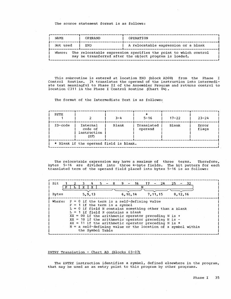
The source statement format is as follows:
r-------------T-------------------T-------------------------------------------, I NAME I OPERAND I OPERATION I t-------------+-------------------+-------------------------------------------~ I Not used I END I A relocatable expression or a blank I t-------------L-------------------L-------------------------------------------~ I Where: The relocatable expression specifies the point to which control I I may be transferred after the object program is loaded. I l _________________________ ~ ___________________________________________________ J
This sUbroutine is entered at location END (block AD08) from the Phase I Control Routine. It translates the operand of the instruction into inte~mediate text meaningful to Phase II of the Assembler Program and returns control to location C311 in the Phase I Control Routine (Chart 04).
The format of the Intermediate Text is as follows:
r-----------T-------------T------------T------------T------------T------------, I BYTE I I I * I I I I 1 I 2 I 3-4 I 5-16 I 17-22 I 23-24 I t-----------+-------------+------------+------------+------------+------------~ lID-code I Internal I Blank I Translated I Blank I Error I I I code of I I operand I I flags I I I instruction I I I I I I I (EF) I I I I I t----------~.1.-____________ .1. ____________ .1. ____________ .1._-----------.1.------------4 I * Blank if the operand field is blank. . I l _____________________________________________________________________________ J .
The relocatable expression may have a maximum of three terms. Therefore, bytes 5-16 are divided into three 4-byte fields. The bit pattern for each translated term of the operand field placed into bytes 5-16 is as follows:
r-----------------------------------------------------------------------------, I Bit 1 2 3 4 5 8 9 16 17 24 25 32 I I IplLlxlxl N I I I '" y , \. V I '----v----" '------y----J I I Bytes 5,9,13 6,10,14 7,11,15 8,12,16 I ~-----------------------------------------------------------------------------~ I Where: P 0 if the term is a self-defining value I I P 1 if the term is a symbol I I L = 0 if field N contains something other than a blank I I L = 1 if field N contains a blank I I xx 00 if the arithmetic operator preceding N is + I I xx = 10 if the arithmetic operator preceding N is - I I xx = 11 if the arithmetic operator preceding N is * I I N = a self-defining value or the location of a symbol within I I the Symbol Table I l _____________________________________________________________________________ J
ENTRY Translation - Chart AD (Blocks 03-07)
The ENTRY instruction identifies a symbol, defined elsewhere in the program, that may be used as an entry point to this program by other programs.
Phase I 35

The source statement format is as follows:
r-------------T-------------------T-----------------~-------------------------, I NAME I OPERATION I OPERAND I ~-------------+-------------------+-------------------------------------------~ I Not used I ENTRY I A relocatable symbol I L _____________ L ___________________ L ___________________________________________ J
This subroutine is entered at location ENTRY (block AD07) from the Phase I Control Routine. It translates the operand of the instruction into intermediate text meaningful to Phase II of .the Assembler Program and returns control to location C311 in the Phase I Control Routine (Chart 04).
The format of the Intermediate Text is as follows:
r----------T-----------T----------T----------T----------T----------T----------, I BYTE I I I I I I I I 1 I 2 I 3- 4 I 5- 8 I 9-14 I 15-2 2 I 23-2 4 I ~----------+-----------+----------+----------+----------+----------+----------~ lID-code I Internal I Blank I Translated I Actual I Blank I Error I I I code of I I operand I symbol I I flags I I I instruction I I I from I I I I I (EA) I I I operand I I I L __________ L ___________ ~ __________ ~ __________ ~ __________ ~ __________ ~ __________ J
The bit pattern of the translated relocatable symbol placed into bytes 5-8 is as follows:
r-----------,------------------------------------------------------------------, I Bit 1 2 3 4 5 8 9 16 17 24 25 32 I I lP I L I XJ X N. I I I /~~~I I Byte 5 6 7 8 I ~-----------------------------------------------------------------------------~ I Where: P = 1 since the operand is a symbol I I L = 0 since field N will contain something other than a blank I I XX = 00 since the location of the symbol is always positive I I N'= the location of a symbol within the Symbol Table I L ________________________________________________________ ~ ____________________ J
EQU Translation - Chart AE (Blocks 01-08)
The EQU instruction is used to assign to a symbol in the name field the same length and attributes as an expression in the operand field.
The format of the source statement is as follows:
r-------------T-------------------T-------------------------------------------, I NA.I'IlE I OPERATION I OPERAND I ~-------------+-------------------+---------------------------,----------------~ I Required I EQU I An expression (any symbols in the I I I I expression must be previously defined) I L _____________ L ___________________ ~ ___________________________________________ J
This subroutine is entered at location EQU (block AE01) from the Phase I Control Routine. It translates the operand of the instruction into intermediate text meaningful to Phase II of the Assembler Program and returns control to location C311 in the Phase I Control Routine (Chart 04).
36

The format of the Intermediate Text is as follows:
r-----------T-------------T------------T------------T------------T------------, I BYTE I I I I I I I 1 I 2 I 3-4 I 5-16 I 17-22 I 23-24 I
~-----------+-------------+------------+------------+------------+------------~ lID-code I Internal I Blank I Translated I Blank I Error I
I I code of I I operand I I flags I I I instruction I I I I I
I I (E5) I I I I I l ___________ ~ _____________ ~ ____________ ~ ____________ ~ ____________ ~ ____________ J
The operand field may have a maximum of three terms. Therefore, bytes 5-16 are divided into three 4-byte fields. The bit pattern for each translated term is as follows:
r-----------------------------------------------------------------------------, I Bit 1 2 3 4 5 8 9 16 17 24 25 32 I I Ip I L I X I X I N I I I '- y / '----y---/ ~ ~ I I Bytes 5,9~13 6,10,14 7,11,15 8,12,16 I ~-----------------------------------------------------------------------------~ I Where: P 0 if the term is a self-defining value I I P 1 if the term is a symbol I I L = 0 if field N contains something other than a blank I I L = 1 if field N contains a blank I I XX 00 if the arithmetic operator preceding N is + I I XX = 10 if the arithmetic operator preceding N is - I I XX = 11 if the arithmetic operator preceding N is * I I N = a self-defining value of the location of a symbol within I , the Symbol Table I L _____________________________________________________________________________ J
EXTRN Translation - Chart AE (Blocks 09-14)
The EXTRN instruction identifies a linkage symbol as an external symbol defined in some other program that will be referred to in this program.
The source statement format is as follows:
r-------------T-------------------T-------------------------------------------, I NAME I OPERATION I OPERAND I ~-------------+-------------------+-------------------------------------------~ I Not used I EXTRN I A relocatable symbol I l _____________ ~ ___________________ ~ ___________________________________________ J
This SUbroutine is entered at location EXTRN (block AE09) from the Phase I Control Routine. It translates the operand of the instruction into intermediate text meaningful to Phase II of the Assembler Program and returns control to location C311 in the Phase I Control Routine (Chart 04).
Phase I 37

The format of the Intermediate Text is as follows:
r----------T-----------T----------T----------T----------T----------T----------, , BYTE' I I , , , , , 1 , 2 I 3-4 , 5-8 I 9-14 , 15-22 I 23-24 , ~----------+-----------+----------+----------+----------+----------+----------i ,ID-code I Internal , Blank ,Translated, Actual , Blank , Error , I , code of , I operand , symbol , , flags , I ,instruction, , ,from, , , , '(E9) , , , operand, , , l __________ ~ ___________ ~ __________ ~ __________ ~ __________ ~ __________ ~ __________ J
The bit pattern of the translated relocatable symbol placed into bytes 5-8 is as follows:
r---------------------~------------------------------------------------------, I Bit 1 2 3 4 5 - 8 9 - 16 17 - 24 25 - 32 , I Ip I L I X I X I N I , I l y I "----y-----J "------y----I ~ I I Byte 5 6 7 8 I ~----------------------------------~---~------------------------------------~ I Where: P = 1 since the operand is a symbol I I L = 0 since field N contains something other than a blank I I XX = 00 since the location of the symbol is always positive I I N = the location of a symbol within the Symbol Table I l _____________________________________________________________________________ J
ICTL Translation - Chart AF (Blocks 01-07)
The ICTL instruction tells the Assembler Program in which column the statement portion of the source program statement begins.
The format of the source statement is as follows:
r-------------T----~--------------T-------~-----------------------------------, I NAME ,OPERATION I OPERAND , ~-------------+-------------------+-------------------------------------------~ I Not used , ICTL , The decimal value 1 or 25 I l _____________ ~ ___________________ ~ ___________________________________________ J
This subroutine is entered at location ICTL (block AF01) from the Phase I Control Routine. When the ICTL instruction is used, it must be the first statement in the source program. This subroutine translates the operand into intermediate text which will be reproduced in the Object program listing. If the operand field is incorrect, Phase I will set the starting column to a 1 for a tape system and to a 25 for a card system. Control returns to location C3l1 in the Phase I Control Routine (Chart 04) •
The format of the Intermediate Text is as follows:
r-----------T-----------------T-----------------T-------------T---------------, I BYTE I I I , , I 1 I 2 I 3-4 I 5-22 I 23-24 , ~-----------+-----------------+-----------------+-------------+---------------~ I ID-code I Internal code I Translated , Blank I Error flags , I , of instruction, operand, , , , I (ED), , , , l ___________ ~ _________________ ~ _________________ ~ _____________ ~ _______________ J
38

ORG Translation - Chart AG (Blocks 01-07)
The ORG instruction is used to set the location counter to a specified address.
The format of the source statement is as follows:
r-------------T-----------------T---------------------------------------------, I NAME I OPERATION I OPERAND I ~-------------+-----------------+------------------------------~-~------------1 I Not used I ORG I A relocatable expression (any symbols iri I I I I the expression must be previously defined) I L _____________ ~ _________________ ~ _____________________________________________ J
This subroutine is entered at location ORG (block AG01) from the Phase I Control Routine. It translates the operand of the instruction into intermediate text meaningful to Phase II of the Assembler Program and returns control to location C311 in the Phase I Control Routine (Chart 04).
The format of the Intermediate Text is as follows:
r-----------T-------------T------------T------------T------------T------------, I BYTE I I I I I I I 1 I 2 I 3-4 I 5-16 I 17-22 I 23"-24 I ~-----------+-------------+------------+------------+------------+------------~ lID-code I Internal I Blank I Translated I Blank I Error I I I code of I I operand I I flags I I I instruction I I I I I I I (E8) I I I I I L ___________ ~ _____________ ~ ____________ ~ ____________ ~ ____________ ~ ____________ J
The relocatable expression may have a maximum of three terms. Therefore, bytes 5-16 are divided into three 4-byte fields~ The bit pattern for each translated term is as follows:
r-----------------------------------------------------------------------------, I Bit 1 2 3 4 5 8 9 16 17 24 25 32 I I Ip I L I X I X I N I I I \ v I "--y----J '-----y------/ '---y-----J I I Bytes 5,9,13 6,10,14 7,11,15 8,12,16 I ~-----------------------------------------------------------------------------1 I Where: P = 0 if the term is a self-defining value I I P = 1 if the term is a symbol I I L = 0 if field N contains something other than a blank I I L = 1 if field N contains a blank I I XX = 00 if the arithmetic operator preceding N is + I I XX = 10 if the arithmetic operator preceding N is - I I XX = 11. if the arithmetic operator preceding N is * I I N = a self-defining value or the location of a symbol within I I the Symbol Table I L _____________________________________________________________________________ J
SPACE Translation - Chart AG (Blocks 08-12)
The SPACE instruction is used to insert one or more blank lines in the object program listing.
Phase I 39

The source statement format is as follows:
r-------------T-------------------T-------------------------------------------, I NAME I OPERATION I OPERAND I ~-------------+---------~---------+--------------~----------------------------~ I Not used I SPACE I A decimal value not greater than 63 I L _____________ i ___________________ i ___________________________________________ J
This subroutine is entered at location SPACE (block AG08) from the Phase I Control Routine. It translates the operand of the instruction into intermediate text meaningful to Phase II of the Assembler Program. If the operand field is blank, the Assembler assumes a value of 1. If the operand field is greater than 63, the SPACE instruction is treated the same as the EJECT instruction by Phase II of the Assembler Program. Control returns to location C311 in the Phase I Control Routine (Chart 04).
The format of the Intermediate Text is as follows:
r-----------T-----------------T-----------------T-------------T---------------, I BYTE I I I I I I 1 I 2 I 3-4 I 5-22 I 23-24 I ~-----------+-----------------+-----------------+-------------+---------~-----~ lID-code I Internal code I Translated I Blank I Error flags I I I of instruction I operand I I I I I (E7) I I I I L ___________ i _________________ L _________________ L _____________ L _______________ J
START Translation - Chart AF (Blocks 08-16)
The START instruction may be used to indicate the beginning of an assembly, to give a name to the object program, and to set the location counter to an initial value.
The format of the source statement is as follows:
r-------------T-------------------T-------------------------------------------, I NAME I OPERATION ,OPERAND , ~-------------+-------------------+-------------------------------------------~ I Optional I START , A self-defining value or blank I L _____________ i ___________________ L ___________________________________________ J
This subroutine is entered at location START (block AF08) from the Phase I Control Routine. It translates the operand of the instruction into intermediate text meaningful to Phase II of the Assembler Program. If the operand field contains an error, the location counter will be set to zero. Control returns to location C311 in the Phase I Control, Routine (Chart 04).
The format of the Intermediate Text is as follows:
r-------T-----------T---------T---------T---------T--------~--------T--------, 'BYTE I I I I , I I I I 1 I 2 I 3 I 4 I 5- 8 , 9-14 , 15-22 I 23-24, ~-------+-----------+---------+---------+---------+---------+--------+--------~ lID-code' Internal I Blank IBoundary I Trans- I Actual I Blank, Error, I 'code of , I alignment I lated 'symbol , I flags, , I instruction I , pattern I operand I from' I I I I (EE) , , I 'name' , , I' I I I I field I I I L _______ L ___________ i _________ i _________ i _________ i _________ i ________ L ________ J
40

The translated operand plaged into bytes 5-8 will be the assembled 2q-bit address of the first byte of the object program.
USING Translation - Chart AH (Blocks 01-07)
The USING instruction indicates that the general register specified is available for use as a register for base addressing. This instruction also states the base-address value that the Assembler may assume will be in the indicated general register at object time.
The source statement format is as follows:
r-------------T-------------------T-------------------------------------------, I NAME I OPERATION I OPERAND I
~-------------+-------------------+-------------------------------------------~ I Not used I USING I A relocatable expression and a simple I I I I expression separated by a comma I
~-------------~-------------------~-------------------------------------------~ I Where: The relocataple expression specifies a value that the Assembler I I can use as a base register. I I I I The simple absolute expression specifies the general register I I that can be assumed to contain the base address represented by I I the relocatable expression. I L ________________________________ ~ ___________________________________________ J
This subroutine is entered at location USING (block AH01) from'the Phase I Control Routine. It translates the operand of the instruction into intermediate text meaningful to Phase II of the Assembler Program and returns control to location C311 in the Phase I Control Routine ~hart 04) •
The format of the Intermediate Text is as follows:
r----------T-----------T----------T----------T----------T----------T----------, I BYTE I I I I I I I I 1 I 2 I 3-4 I 5-16 I 17-20 I 21-22 I 23-2q I
~----------+-----------+----------+----------+----------+----~-----+----------i lID-code I Internal I Blank I Translated I Translated I Blank I Error I I I code of I I relocat- I simple I I flags I I I instruction I I able I expression I I I I I (E6) I I expression I I I I L __________ ~ __________ ~ __________ ~ __________ ~ __________ ~ _____ ~----~----------J
The bit patterns for the translated expression of the operand field placed into the intermediate text are as follows:
Relocatable Expression:
The relocatable expression may have a maximum of three terms. Therefore, bytes 5-16 are divided into three 4-byte fields. The bit pattern for each translated term is as follows:
Phase I 41
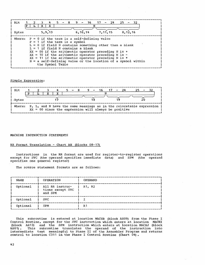
r-----------------------------------------------------------------------------, I Bit 1 2 3 4 5 8 9 16 17 24 25 32 I I Ip I L I x I x I N I I I \. Y J~ '---y----J~ I I Bytes 5,9,13 6,10,14 7,11,15 8,12,16 I t-----------------------------------------------------------------------------~ I Where: P = 0 if the term is a self-defining value I I P = 1if the term is a symbol I I L = 0 if field N contains something other than a blank I I L = 1 if field N contains a blank. I I xx = 00 if the arithmetic operator preceding N is + I I xx = 10 if the arithmetic operator preceding N is - I I xx = 11 if the arithmetic operator preceding N is * I I N = a self-defining value or the location of a symbol within I I the Symbol Table I L _____________________________________________________________________________ J
Simple Expression:
r-----------------------------------------------------------------------------, I Bit 1 2 3 4 5 8 9 16 17 24 25 32 I I IplL xlxl N I I I \. y J'-----v------' \. v ) '--y---J I I·Bytes 17 18 19 20 I t-----------------------------------------------------------------------------~ I Where: P, L, and N have the same meanings as in the relocatable expression I I xx = 00 since the expression will always be positive I L _____________________________________________________________________________ J
MACHINE INSTRUCTION STATEMENTS
RR Format Translation - Chart AH (Blocks 08-17)
Instructions in the RR format are used for register-to-register operations except for SVC (the operand specifies immediate data) and SPM (the operand specifies one general register)
The source statement formats are as follows:
r-------------T--------------------T------------------------------------------, I NAME I OPERATION I OPERAND I t-------------+--------------------+------------------------------------------~ I Optional I All RR instruc- I R1, R2 I I I tions except SVC I I I I and SPM I I t-------------+--------------------+------------------------------------------~ I Optional I SVC I I I t-------------+--------------------+------------------------------------------~ I Optional I SPM I R 1 I L _____________ ~ ____________________ ~ __________________________________________ J
This sUbroutine is entered at location MACHB (block AH09) from the Phase I Control Routine, except for the SVC instruction which enters at location MACHI (block AH13) and the SPM instruction which enters at location MACHJ (block
AH01) • This subroutine translates the operand of the instruction into intermediate text meaningful to Phase II of the Assembler Program and returns control to location C311 in the Phase I Control Routine (Chart 04).
42

The format of the Intermediate Text is as follows:
r-----------T-------------T------------T------------T------------T------------, I BYTE I I * I ** I I I I 1 I 2 I 3-4 I 5-6 I 7-20 I 21-24 I ~-----------t-------------t------------t------------t------------t------------i I ID-code I Internal !.Translated I Translated I Blank I Error I I I code of I R2 or I I R1 field I I flags I I I instruction I field I I I I
~-----------i-------------i--~-----~---i------------i------------i------------i I * Blank if no R2 field. Byte 3 contains the number of zeros to be I I assembled by Phase 2 if an error is encountered. I I ** Blank if SVC instruction. I L _____________________________________________________________________________ J
The bit pattern for the translated R1 field; R2 field, or I field is as follows:
r-----------------------------------------------------------------------------, I Bit 1 2 3 8 9 16 I I I P L N I I I' V )\ V ) I I Bytes 3,5 4,6 I ~-----------------------------------------------------------------------------i I Where: P = 0 if the field is a self-defining value I I P = 1 if the field is a symbol I I L = 0 if field N contains something other than a blank I I L = 1 if field N contains a blank I I N = a self-defining value or the location of a symbol within I I the Symbol Table I L _____________________________________________________________________________ J
RS Format Translation - Chart AI
Instructions in the RS Format are used for register-~o-storage operations and for shift operations.
The source statement formats are as follows:
Format type 1 r------------T--------------------T-------------------------------------------, I NAME I OPERATION I OPERAND I ~------------t--------------------t-------------------------------------------~ I Optional I All instructions I R 1, R3, D2 (B2) , I , except shift I , I I instructions I I L ____________ i ____________________ i _____________________ ~ _____________________ J
Format type 2 r------------T--------------------T-------------------------------------------, I NAME I OPERATION I OPERAND I ~------------t--------------------t~------------------------------------------i I Optional I All shift I R1, D2(B2) I I I instructions I I L ____________ i ____________________ i ___________________________________________ J
This subroutine is entered at location MACHC (block AI01) from the Phase I Control Routine, except for format type 2 which enters at location JVlACHD (block AI02) • This subroutine translates the operand of the instruction into
Phase I 43

intermediate text meaningful to Phase II of the Assembler Program and returns control to location C311 in the Phase I Control Routine (Chart 04).
The format of the Intermediate Text is as follows:
r-------T-----------T---------T---------T---------T---------T.--------T--------, I BYTE I I * I I I * * I I I I 1 I 2 I 3-4 I 5-6 I 7-12 I 13-14 I 15-20 I 21-24 I ~-------+-----------+---------+---------+---------+---------+--------+--------~ IID-codel Internal I Tran~~ I Trans- I Trans- I Trans- I Blank I Error I I I code of I lated I lated I lated I lated I I flags I I I instruction I R3 fieldl R1 fieldl D2 fieldl B2 fieldl I I ~-------~-----------~---------~---------~---------~---------~--------~--------~ I * Blank if not specified or if format type 2 is being translated. I I Byte 3 contains the number of bytes to be assembled as zeros if an I I error is encountered. I I ** Blank if not specified. I L ________ ~ ___________________________________ ~ ________________________________ J
The bit patterns for the translated fields of the operand placed into the Intermediate Text are as follows:
R3 field, R1 field, or B2 field:
r-----------------------------------------------------------------------------, I Bit 1 2 3 8 9 16 I I Ip I· L N I I I \. V /\ V / I I Bytes 3,5,13 4,6,14 I ~----7------------------------------------------------------------------------~ I Where: P 0 if the field is a self-defining value I I P 1 if the field is a symbol I I L = 0 if field N contains something other than a blank I I L = 1 if field N contains a blank I I N a self-defining value or the location of a symbol within I I the Symbol Table I L _____________________________________________________________________________ J
D2 field:
The D2 field may have a maximum of three terms. Therefore, bytes 7-12 are divided into three 2-byte fields. The bit pattern for each translated term is as follows:
r-----------------------------------------------------------------------------, I Bit 1 2 3 4 5 8 9 16 I I Ip I L X I X N I I I \. V J'-------y--I I I Bytes 7,9,11 8,10,12 I ~-----------------------------------------------------------------------------~ I Where: P, L, and N have the same meanings as indicated for the R3, R1, I I and B2 fields I I XX = 00 if the arithmetic operator preceding N is + I I XX = 10 if the arithmetic operator preceding N is - I I XX = 11 if the arithmetic operator preceding N is * I L _____________________________________________________________________________ J
44

RX Format Translation - Chart AJ
Instructions in the RX Format are used for register-to-indexed-storage operations.
The source statement format is as follows:
r-------------T-------------------T-------------------------------------------, I NAME I OPERATION I OPERAND I ~-------------+-------------------+-------------------------------------------~ I Optional I Any RX I R1,D2(B2,X2) I I I instruction I I L _____________ ~ ____ ~ ______________ ~ ______________________________ ~ ____________ J
This subroutine is entered at location MACHA (block AJ01) from the Phase I Control Routine. It translates the operand of the instruction into intermediate text meaningful to Phase II of the Assembler Program and returns control to location C311 in the Phase I Control Routine (Chart 04).
The format of the Intermediate Text is as follows:
r-------T-----------T---------T---------T---------T---------T--------T--------, I BYTE I I * I I I * I I I I 1 I 2 I 3-4 I 5-6 I 7-12 I 13-14 I 15-20 I 21-24 I ~-------+-----------+---------+---------+---------+-----~---+--------+--------~ IID-codel Internal I Trans- I Trans- I Trans- I- Trans- I Blank I Error I I I code of I lated I lated I lated I lated I I flags I , ,instructionl X2 fieldl R1 field, D2 fieldl B2 fieldl I I ~-------~-----------~---------~---------~---------~---------~--------~--------~ I * Blank if not specified. Byte 3 contains the number of bytes to be I , assembled as zeros if an error is encountered. I L _____________________________________________________________________________ J
The bit patterns for the translated fields of the operand placed into the Intermediate Text are as follows:
X2 field, R1 field, or B2 field:
r-----------------------------------------------------------------------------, , Bit 1 2 3 8 9 16 I I I·p I L N I I I \. V I\. Y J I , Bytes 3,5,13 4,6,14 I ~-----------------------------------------------------------------------------i I Where: P = 0 if the field is a self-defining value I I P = 1 if the field is a symbol I , L = 0 if field N contains something other than a blank I , L = 1 if field N contains a blank I , N a self-defining value or the location of a symbol within , I the Symbol Table , L _____________________________________________________________________________ J
D2 field:
The D2 field may have a maximum of three terms. Therefore, bytes 7-12 are divided into three 2-byte fields. The bit pattern for each translated term is as follows:
Phase I 45

r-----------------------------------------------------------------------------, , Bit 1 2 3 4. 5 8 9 16 I , Ip I L I x I x I N I I ,\. V / '-----v-----" , , Bytes 7,9,11 8,10,12 ,
~-----------------------------------------------------------------------------~ ,Where: P, L, and N have the same meanings as indicated for the , , X2, R1, and B2 fields , , xx = 00 if the arithmetic operator preceding N is + , , xx = 10 if the arithmetic operator preceding N is - , , xx = 11 if the arithmetic operator preceding N is * , L _____________________________________________________________________________ J
•
SI Format Translation - Chart AK
Instructions in the SI Format are used for storag~ and immediate data operations.
The source statement formats are as follows:
Format type 1 r------------T--------------------T-------------------------------------------, ,NAME ,OPERATION , OPERAND , ~------------+--------------------+-------------------------------------------1 , Optional , All SI instruc- , D1 (B1) ,12 , , , tions except , , , , those in format , , , , type 2 I , L ____________ ~ ____________________ ~ ___________________________________________ J
Format type 2 r------------T--------------------T-------------------------------------------, ,NAME ,OPERATION , OPERAND , ~--------~---+--------------------+-------------------------------------------1 , Optional ,LPSW,SSM,H10, 'D1 (B1) , , ,SIO,TIO,TCH,TS, , L ____________ ~ ____________________ ~ ___________________________________________ J
This subroutine is entered at location MACHE (block AK01) from the Phase I Control Routine, except for format type 2 which enters at location MACHF (block AK02). It translates the operand of the instruction into intermediate text meaningful to Phase II of the Assembler Program and returns control to location C311 in the Phase I Control Routine (Chart 04) •
The formats of the Intermediate Text are as follows:
Format type 1 r----------T-----------T----------T----------T----------T----------T----------, 'BYTE , . , *' '* *' I , I 1 , 2 , 3-6 , 7-12 I 13-14 , 15-20 , 21-24 I ~----------+-----------+----------+----------+----------+----------+----------~ 'ID-code ,Internal ,Translated, Translated I Translated I Blank , Error , , I code of ,I field 'D1 field , B1 field , , flags , I ,instruction' , , , , I ~----------~-----------~----------~----------~----------~----------~----------~ , * Byte 3 contains the number of bytes to be assembled as zeros if an I , error is encountered. I , ** Blank if not specified. , L _____________________________________________________________________________ J
46
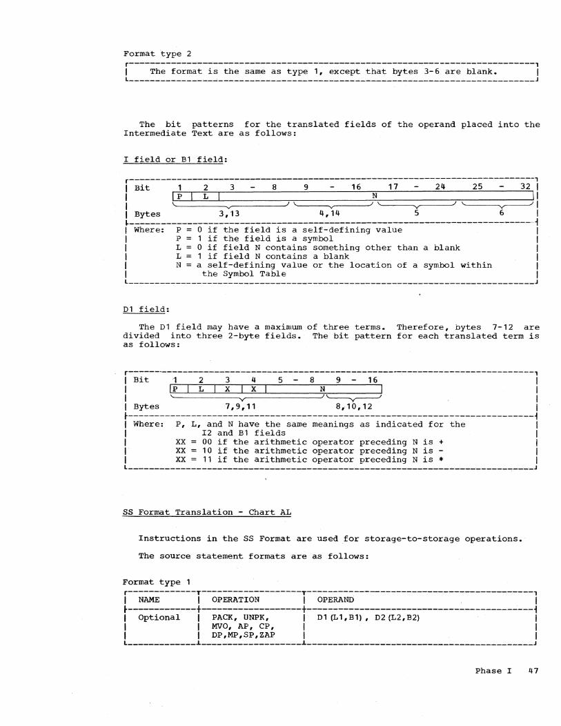
Format type 2 r-----------------------------------------------------------------------------, I The format is the same as type 1, except that bytes 3-6 are blank. I l ______________ ~_~ ____________________________________________________________ J
The bit patterns for the translated fields of the operand placed into the Intermediate Text are as follows:
I field or B1 field:
r-----------------------------------------------------------------------------, I Bit 1 2 3 - 8 9 - 16 17 - 24 25 - 32 I I I P I LIN II I \. v )\. v -''- v )~I I Bytes 3,13 4,14 5 6 I ~----------------------------~-------------------------------------------------~ I Where: P 0 if the field is a self-defining value I I P 1 if the field is a symbol I I L 0 if field N contains something other than a blank I I L 1 if field N contains a blank I I N a self-defining value or the location of a symbol within I I the Symbol Table I L _____________________________________________________________________________ J
D1 field:
The D1 field may have a maximum of three terms. Therefore, bytes 7-12 are divided into three 2-byte fields. The bit pattern for each translated term is as follows:
r------------------------------------------------------------------------------, I Bi t 1 2 3 4 5 8 9 1 6 I I Ip L I X I X I N I I I' V / '---y----I I I Bytes 7, 9, 11 8, 1 0, 12 I ~-----------------------------------------------------~-----------------------i I Where: P, L, and N have the same meanings as indicated for the I I I2 and B1 fields I I XX = 00 if the arithmetic operator preceding N is + I I XX = 10 if the arithmetic operator preceding N is - I I xx = 11 if the arithmetic operator preceding N is * I l _____________________________________________________________________________ J
SS Format Translation - Chart AL
Instructions in the SS Format are used for storage-to-storage operations.
The source statement formats are as follows:
Format type 1 r-------------T-------------------T-------------------------------------------, I NAME I OPERATION I OPERAND I ~-------------+-------------------+-------------------------------------------i I Optional I PACK, UNPK, I 01 (L1,B1), 02 (L2,B2) I I I MVO, AP, CP, I I I I OP,MP,SP,ZAP I I l _____________ i ___________________ i ___________________________________________ J
Phase I 47

Format type 2 r------------T--------------------T-------------------------------------------, I NAME I OPERATION I OPERAND I t-~----------+--------------------+-~-----------------------------------------~ I _Optional I All other SS I D1 (L,B1) ,D2 (B2) I I . I instructions I· I L ____________ ~ ____________________ ~ ___________________________________________ J
This subroutine is entered at location MACHG (block AL01) from the Phase I Control Routine, except for format type 2 which enters at location MACHH (block AL02) • It translates the operand of the instruction into intermediate text meaningful to Phase II of the Assembler Program and returns control to location C311 in the Phase I Control Routine (Chart 04) •
The formats of the Intermediate Text are as follows:
Format type 1 r-----T--------T--------T--------T--------T--------T--------T--------T--------, I BYTE I I * I * I I * I * I * I I I 1 I 2 I 3-4 I 5-6 1·7-12 I 13-14 I 15-20 I 21-22 I 23-24 I ~-----+--------+--------+--------+-----~--+--------+--------+--------+--------~ IID- I Internal I Trans- I Trans- I Trang- I Trans- I Trans- I Trans- I Error I Icode Icode of I lated I lated I lated I lated I lated I lated I flags I I linstruc-I L2 I L1 ID1 I B1 I D2 I B2 I I I I tion I field I field I field I field I field I field I I ~-----~--------~--------~--------~--------~--------~-~------~--------~--------~ I * Blank if not specified. Byte 3 contains the number of bytes to I I be assembled as zeros if an error is encountered. I L __ ---------------------~-----------------------------________________________ J
Format type 2 r-----------------------------------------------------------------------------, I The format is the same as type 1, except that bytes 3-4 contain the I I translated L field and bytes 5-6 are blank. I L _____________________________________________________________________________ J
The bit patterns for the translated fields of the operand placed into the Intermediate Text are as follows:
L or L2 field, L1 field, B1 field, or B2 field:
r--------------------------------------------------------------------~--------, I Bit 1 2 3 8 9 16 I I I p I L N I I " v )~ I I Bytes 3,5,13,21 4,6,14,22 I ~-----------------------------------------------------------------------------~ I Where: P = 0 if the field is a self-defining value I I P = 1 if the field is a symbol I I L = 0 if field N contains something other than a blank I I L = 1 if field N contains a blank I I N = a self-defining value or the location of a symbol within I I the Symbol Table I L _____________________ ~ _______________________________ ~ _____________________ -J
D1 field or .D2 field:
The D1 field and the 02 field may contain a maximum of three terms. Therefore, bytes 7-12 and 15-20 are divided into three 2-byte fields. The bit pattern for each translated term is as follows:
48

r------------------------~----------------------------------------------------, I Bit 1 2 3 4 5 8 9 16 I I Ip I L I x I x N I I I \ v I~ I I Bytes 7,9,11,15,17,19 8,10,12,16,18,20 I ~--------------------------------------------~--------------------------------~ I Where: P, L, and N have the same meanings as indicated for the I I L, L1, L2, Bl, and B2 fields I I xx = 00 if the arithmetic operator preceding N is + I I xx = 10 if the arithmetic operator preceding N is - I I xx = 11 if the arithmetic operator preceding N is * I l _____________________________________________________________________________ J
Phase I 49


****43********* · . * ST ART PHASE 1 * · . ***************
X 01 *****83****·***** :~~~~~*-*-*-*-*-: *READ IN PHASE 1* * OF * * ASSEMBLER * *****************
X 02 *****C3********** •. * : ESTABLISH * *ADORESSABILITY * • 0 *****************
X 03 *****03********** *DETERMINE MAIN * * STORAGE SIZE * * AND GEN~RATE * * CONTROL * PARAMET~R$ * *****************
X 04 *****E!********** * CLEAR SYMBOL * * TABLE AREA * * AND * • RESERVE FIRST * * TWO ENTRIES * *****************
08 .X. *****F2********** F3 *. 05 * * .* *. * GET INPUT AND * YES.* IS *. * OUTPUT *X •••••••• *. INPUT .* * ADDRESSES AND * *. 1442 .* * STORE * *..* ***************** ~ •• *
o NO
X 09 .X. *****G2*.******** G3 *. 06 *SET OUTPUT SIZE* .* *. * OF * .* IS *. YES
07 *****G4********** * •
* INTERMEDIATE * •••••••• x*. OUTPUT .* •••••••• x* SET
MOVE DATA SWITCH
. . * TEXT * *. TAPE.* * * TO 24 BYTES * *..* * ***************** * •• * *****************
* NO
X 10 *****H3**********
• * SET * MOVE DATA * * SWITCH * · *****************
X 11 *****H4********** *SET OUTPUT SIZE* * OF * * INTERMEDIATE * * rEXT * * TO 104 !SYTES * *******~*.*******
X 13 X 12 *****J3********** *****J4********** *INOUr * * * *-*-*-*-*-*-*-*-* -STORE TAPE UNIT*
READ *X •••••••• * OUTPUT * NEXT SOURCE * * ADDRESS
* STATEMENT * ***************** *****************
15 .X. *****K2********** K3 *. 1. *INOUT * .* *. *-*-*-*-*-*-*-*-* YES.* IS *. NO
•••••••• * READ *X •••••••• *.CARD A SYMBOL.* •••••••• X * SYMBOL TABLE * *T ABLE CARD * X
***** * DECK * *..* ***** *04 * ***************** *. .* *04 * ... B1* * * S1* • * * * *
Chart 03. Phase I Initialization
Phase I 51

***** *04 * * 81* . .
.X •••••••••••••••••••••••••••••••••••••••••••••••••••••••••••••••••••••••••••••
X 01 *****91********** *INOUT * *-*-*-*-*-*-*-*-*
• YES 11 .*.
•• * •• B~.**** •• *** 84 *. 16 *EVE AMB~* .* *. *-*-*-*-*-*-*-*-*NONE.* *.
***** *04 * * 85* .. . ..
* 85 *.X. . . ****
C311 .x • 65 *. 20
.* *. * READ •
SOURCE ••• X* SCAN FOR * •••••••• X*. BLANK .*
NO .* STATEMENT *. ••• *. TO BE .* *.ASSEMBLED.*
* STATEMENT * *********.******.
X 02 *****Cl********** * SET COLUMN TO * *START SCAN. seT* * NECESSARY * *S~ITCHES. BLANK* * PUNCH BUFFER • *****************
.x. 01 *. 03
.* *. .* [5 *. YES *. COLUMN 72 .* ••.••
*. BLANK .* *. .* * •• *
• NO
X 04 *****El********** * STORE ERROR *
FLAG Z • IN * INTERMEDIATE * TEXT * ************.****
· . • X •••••••••••
.x. Fl *. 05
.* IS *. .* STARTING *. YES •
*. COLUMN .* •••••••••••••••••••••••••••••• X. *. BLANK .*
*. .* * •• * • NO
.x. 08 G 1 *. 06 *****G2**********
.* *. *EVE AMB3* .* *. NO *-*-*-*-*-*-*-*-*ERR
*. COMMENTS .* •••••••• X*SCAN NAME FIELC* •••• *. .* * * *..* *C=40 *
* •• * ***************** * YES .CORRECT
X 07 *****Hl********** * STORE *
ID-CODE 'C' * INTO * * [NTERNED[ ATE * * TEXT *****************
x ***** *05 * * F2* . .
X 09 *·**·H2******·*** * SAVE SY~BOL * *FROM NAME FIELD*
•••• * AND SET VALID * *NAME INDICATOR * . . *****************
10 *****J2********** * STORE ERROR * * FLAG (L) * * [N *X •••• * [NTERMEDIATE * * TEXT * *****************
x
Chart 04. Phase I Control Routine
52
*OPERATION CODE * *. .* *C=40 * *..* ***************** *. .* x
***** *05 * * F2*
.FOUND * NO .. X 12 X 17
*****C~********** *****C4********** *eVE AMB3*NOT IN *ERR * *-*-*-*-*-*-*-*-*TABLE *-*-*-*-*-*-*-*-* *SCAN OPERATION * •••••••• X* STORE ERROR * * CODe TABLE * * FLAGS (NO) IN * *C=40 * .BYTES 23 AND 24* ***************** *****************
.FOUND IN
.TABLE
X 13 *****03********** * STORE OP CODE * *IN INTERMEDIATE* TEXT * * SET BRANCH TO * *TRANS. OPERAND * *****************
x •• *** *05 * * F2* ..
.x. 18 E3 *. 14 *****E4**********
.* *. * SET ID-CODE A * .* MACHINE *. YES INTO BYTE 1 *
*. OPERATION .* •••••••• X* seT NAME *. CODE.* * ALLOWED *..* * IND[CATOR *
*. .* ***************** • NO
X 15 *****F3··*··***** . .
seT * * ID-CODE 8 * * INTO BYTE 1 . . *****************
X 19 *****F4********** *EVE AMB3* *-*-*-*-*-*-*-*-* *ALIGN LOC. CTR.* TO HALF-WORD * * BOUNDARY * ***********.***** · . • x •••••••••••••••••••••••••
******************************** TRANSFER TO SUBROUTINE TO
* TRANSLATE OPERAND FIELD * ******************************** * OPERAT[ON • LOCAT[ON • CHART * * •••••••••••••••••••••••••••••• * * CCW • ccw • AAB2 * * •••••••••••••••••••••••••••••• * * CNOP • CNOP • ACBl • * •••••••••••••••••••••••••••••• * * DC • DC • A882 * * •••••••••••••••••••••••••••••• * * DROP • DROP • ADG4 * * •••••••••••••••••••••••••••••• * * OS • OS • ACA4 * * •••••••••••••••••••••••••••••• * * EJECT • EJECT • ADBI * * •••••••••••••••••••••••••••••• * * ENO • ENO • Aoe4 * * •••••••••••••••••••••••••••••• * * ENTRY • ENTRY • ADFI * * ••••••••••••••••••••••••.••••• *
• * EQU • EQU • AECI *
*. .* * •• * * YES
x ***** *05 * * B2* .. .
•••••••••••• X* •••••••••••••••••••••••••••••• * •••• x* e5 * * EXTRN • EXTRN • AEC4 * * * * •••••••••••••••••••••••••••••• * * ICTL • ICTL • AF61 * * •••••••••••••••••••••••••••••• * * ORG • ORG • AGCl * * ••••••• ~ .••••••••••••••••••••••• * SPAce • SPACE • AGC4 * * •••••••••••••••••••••••••••••• * * START • START • AFB4 * * •••••••••••••••••••••••••••••• * * USING • USING • AHal * * •••••••••••••••••••••••••••••• * * RR • MACHB • AHB4 * * •••••••••••••••••••••••••••••• * * RR(SVC) • MACHI • AHF4 * * ••••••••••••••••.•••••••••••.••• * * RR(SPM) • MACHJ • AHB3 * * •••••••••••••••••••••••••••••• * * RSI • MACHC • AIA2 * * •••••••••••••••••••••••••••••• * * RS2 • MACHO • AI82 * * •••••••••••••••••••••••••••••• * * RX • MACHA • AJB2 * * •••••••••••••••••••••••••••••• * * S[1 • MACHE • AKB3 * * •••••••••••••••••••••••••••••• * * S[2 • MACHF • AK82 * * •••••••••••••••••••••••••••••• * * SSI • MACHG • ALAI * * •••••••••••••••••••••••••••••• * * SS2 • MACHH • ALBI * * •••••••••••••••••••••••••••••• *

***** *05 * * 82* * *
.*. .X. 00 91 *. OS 82 *. 01 *****B3**********
.* *. .* NAME *. *STORE LOCATION * NO .* *. NEITHER .*ALLOWED AND*. BOT~ * COUNTER IN *
•••• *. NAME ERROR .*X •••••••• *. VALID NAME .* •••••••• X*VALUE ATTRIBUTE* *. .* X *INDICATORS * * OF NAME IN * *..* *. SET .* * SYMBOL TABLE *
* •• * * •• * ***************** * YES * CNE
.x. C2 *. 02
.* *. • NO .*VALIO NAME *. •••••• *. INDICATOR .*
*. SET .* *. .* * •• * * YES
X 03 *****02********** * STORE ERROR * * FLAG (L) * IN * INTERMEDIATE * TeXT *****************
X 07 *****C~********** *TLUN * *-*-*-*-*-*-*-*-* * STORE IN * * SYMBOL TABLE * • *****************
.x. 03 *. OB
.* ERROR *. YES.* IN TLUN *.
•••••• *. PROCESSING .* *. .* *. ••
* •• * * NO
. . . ••• •••••••••••••••••••• •• x.X •••••••••••
x O' *****E2********** * STORE IO-CODE -* J OR K IN • * BYTE 1 * ACCORDING TO *OPERATION CODE -**-***.*.*******-
. . . ••••••••••••••••••••••••••••••••••• •• x.x •••••••••••••••••••••••••
• X. .*. 13 F2 *. 09 F3 *. 12 *****F4**********
**** .* *. .*OUTPUT *. * MOVE * * *.* *. NO .* RECORD *. NO * INTERMEDIATE *05 * ••• X*. 1442 SYSTEM .* •••••••• X*. IN OUTPUT .* •••••••• X* TEXT * * F2* *. .* *. AREA.* * TO * **** *..* . *..* * OUTPUT AREA *
* •• * * •• * ***************** * YES * YES
. . ••••••••••••••••••••••••• X •
• X. .*. X 14 G2 *. 10 G3 *. 20 *****G4**********
.* *. .* *. *INOUT * • * DOES *. NO .* *. YES *-*-*-*-*-*-*'-*-*
*. INPUT EQUAL .* •••••••• X*IS INPUT BLANK * •••••••• X* WRITE * *. OUTPUT .* *. .* X * INTERMEDIATE * *..* *..* * TeXT *
*. • * *. .* ***************** * YES * NO
x ****
* * * H4- * * • ****
X 21
. . * H4 *.X. • *
.x. H4 *. 15
.* *.
.*. F5 *. 16
.* * • • * *. YES ••• x*. TAPE SYSTEM .* ••••
*. .* *. .* * •• * • NO
X 17 *****G5********** *INOUT * *-*-*-*-*-*-*-*-* * PUNCH * * SYMBOL TABLE .. OECK * *****************
. .
.x ••••••••••• X 18
*****H3********** * BLANK * * PUNCH BUFFER * * AND STORE 9 * *PUNCH IN PUNCH * * BUFFER COL 1 * *.***************
.* END *. YES •
*****H5********** * RELOCATE * * SYMBOL TABLE
* • * Kl * . .
X **K 1 **** ***
IPL PHASE II _AND TRANSFER *'
.. CONTROL TO * * PHASE II * * * ****** .. ****
. . • J2 * * • ****
X *****J2********** * INOUT * *-*-*-*-*-*-*-*-* * PRINT * * END PHASE I * * MESSAGE * ~****************
X ***'*K2*·*******
.. WAIT FOR *'
.. PHASE II .. • TO BE LOADED *
***************
.x. .13 *. 22
.* *. • * PRINTER *. YES •
*. ON .* •••• X. *. LINE .* *. .*
* •• * • NO
X 23 ****K3*********
* * HAL T' * •••••• . . ***************
Chart 05. Phase I Control Routine (continued)
*. STATEMENT .* •••••• • TO *. .* *. .* * •• *
• NO
X 11 *****j4********** *BUMP * *-*-*-*-*-*-*-*-• * INCREMENT *
LOCATION * COUNTER •
****************'*
x ***** *04 * * Bl* . .
UPPER MAIN * * STORAGE * *****************
.x. J5 *. 19
.* *. NO.* CARD *.
••• *. ASSEMBLER .*
x **** * •
* Kl * * •
*. .* *. .* * •• * * YES
x ****
* * * .12 * . .
Phase I 53

***** *AA * * B2* * * *
**** * * * B4 * * * ****
CCW X 01 . X 08
*****B2********** *eAR * *-*-*-*-*-*-*-*-* *ALIGN LOC. CTR.* *TO DOUBLE-WORD * * BOUNDARY * *****************
X 02 *****C2********** *EVE AM83* *-*-*-*-*-*-*-*-*ERR *TRANSLATE FIRST ••••••• * TERM * *PC=OI C=OO T=OI* *****************
.CORRECT
X 03 *****02********** *STORE * *-*-*-*-*-*-*-*-* * STORE INTO * * INTERMEDIATE * * TEXT * *****************
*****B4********** *EVE AMB3*
ERR*-*-*-*-*-*-*-*-* •••••• *TRANSLATE THIRO*
* TERM * *PC=21 C=OO T=OI* *****************
.CORRECT
X 09 *****c.******-*** *STORE * *-*-*-*-*-*-*-*-* * STORE INTO * * INTERMEDIATE * * TEXT * *****************
.X. 04 *. 10
.* *. • NO.* NEXT *. .X •••• *. CHARACTER A .*
*. COMMA .* *. .*
* •• * * YES
· . • x. 14 X 11 E2 *. 04 *****E3********** *****E4********-*
.* *. • *STORE NUMBER OF*. *EVE AMB3* .* NEXT *. NO X * BYTES TO ZERO * X ERR*-*-*-*-*-*-*-*-*
*. CHARACTER A .* •••••••• X* AND IO-COOE M *X •••••••• * TRANSLATE * *. COMMA.* X *IN INTERMEDIATE* X * FOURTH TERM * *..* * TEXT * *PC=17 c=oo T=OI*
* •• * ***************** ***************** * YES .CORRECT
X OS *****F2********** *EVE AMB3* *-*-*-*-*-*-*-*-*ERR • * TRANSLATE * •••• X. * SECOND TERM * *PC=03 C=BO T=02* *****************
• CORR.ECT
· X 06 *****G2********** *STORE * *-*-*-*-*-*-*-*-* * STORE INTO * * INTERMEDIATE * * TEXT * *****************
.X. H2 *. 07
.* *. .* NEXT *. NO •
*. CHARACTER A .* •••••• *. COMMA .*
*. .* * •. *
* YES·
· X ****
.. * * 84 * * * ****
. X IS
*****F3********** *EAR * *-*-*-*-*-*-*-*-* * STORE ERROR * * FLAG IN * * BYTE 24 * *****************
X 12 *****F4********** *STORE * *-*-*-*-*-*~*-*-* * STORE INTO * * INTERMEDIATE * * TEXT * *****************
. .X. G4 *. 13
.* *. • NO.* NEXT *. ..•••. *. CHARACTER A .*
*. BL..ANK .-*. .*
*. .* * YES . .
•••••••.••.••.•.•••.•..•. x. X
***** *04 * * B5* * * *
Chart M. CCW Translation
54

***** *AB * * B2* * * *
DC .X. B2 *. 01
• * *.
**** * * * B4 * * * ****
. • X.
84 *. 11 .* * •
.* IS *. NO NO .* IS THERE *. •••• *.A DUPLICATION.*
*. FACTOR .* *. CODe TYPE .* •.••.••.••..•...••
*. A .* *. .*
*. .* * YES
. X 02
*****C2********** *CCF * *-*-*-*-*-*-*-*-*ERR * TRANSLATE * •••••• * AND * * STORE * *****************
.CORRECT
. . ............ x.
NO
.X. 02 *. 03
• * *. .* IS *. NO •
*. CODE TYPE .* .••. X. *. CORRECT .*
*. .* * •• *
* YES
.X. E2 *. 04
.* *.
*.. .* * •• * * YES
X 13 *****C4********** *EVE AMB3*
ERR*-*-*-*-*-*-*-*-* • ••••• * TRANSLATE *
* CONSTANT * *PC=07 C=BO T=02* *****************
.CORRECT
.X. 04 *. 14
.* * • • NO.* NEXT * • • X •••• *. CHARACTER A .*
*. BLANK .* *. .*
**** * *
* •• * * YES
* E4 *.x. * * ****
X 15 *****E4********** * MULTIPLY * * DUPLICATION *
X 12 **************** * * * LINK TO * * SUBROUT INE * * ACCORDING * * TO TYPE CODE * * * **************** * C DCC * * •••••••••••••• * * 0 • oeD * * •••••••••••••• * * E DCE * * •••••••••••••• * * F DCF *
ERR:··H··:·'OCH···: • •• * •••••••••••••• *
* x • DCX * X ****************
**** .CORRECT * * * F3 * * * ****
.* IS *. •..• *. CODE TYPE .*
*. A .* * FACTOR BY *X •••••••••••••••••
*. .* *. .*
* YES
**** * * * F3 * * * ****
* LENGTH CODE * * AND STORE * *****************
.X. X 18 .X. F2 *. 05 *****F3********** F4 *. 16
.* *. • *ERR *. .* * • • * IS THERE *. YES X *-*-*-*-*-*-*-*-* X YES.* RESULT *.
*.A OUPLICATION.* •••••••• X* STORE ERROR *X •••••••• *.GREATER THAN .* *. FACTOR.* X * FLAGS IN * * •. 65535 .* *..* *SYTES 23 AND 24* *..*
* •• * ***************** * •• * * NO * NO
**** * * * E4 * * * ****
. X 06
*****G2********** * STORE * * INTERNAL CODE * * FOR TYPE A IN * * INTERMEDIATE * * TEXT * *****************
X • • ••••••••••• X.
• YES • .*. X 07 H1 *. 08 *****H2**********
.* *. * STORE * .* NEXT *. * BOUNDARY *
*. CHARACTER·A .*x· •••••••• *ALIGNMENT BITS * *. BLANK .* * ACCORDING TO * *..* * TYPE CODE *
*. .* ***************** * NO
.x. 10 Jl *. 09 *****J2**********
.* *. *CCF * .* IS *. NO *-*-*-*-*-*-*-*-*ERR.
*. CODE TYPE .* •••••••• X* TRANSLATE * •••••• *H. E, OR 0 * * LENGTH * *..* * CODE *
* •• * ***************** * YES .CORRECT
X ****
* * * F3 * * * ****
Chart AB.
X
**** * * * B4 * * * ****
DC Translation
X 17 .*****G4********** * * *SET PARAMETERS * * FOR BUMP * * SUBROUTINE * * * ***************** . .
•••.••.••...••••.......•. x. X
***** *04 * * 85*
* *
Phase I 55

***** *AC * * Bl* . .
CNOP X 01 *****81********** *EVE AMB3* *-·-*-*-*-*-*-*-*ERR *TRANSLATE FIRST ••••••••••••••••••• *TERM M=6* *PC=03 C=10 T=03* ***** .... **********
.CORRECT
X 02 *****Cl********** *STORE * *-*-*-*-*-*-*-*-* ... STORE INTO * * INTERMEDIATE • • TEXT * * •• ******** ******
X 03 *·***01********** · . *STORE MMM BITS • *IN INTERMEDIATE* * TEXT * · . *****.***********
.x. El *. 04
• * *. .* NEXT *. NO • *. CHARACTER A .* •••••••••••••••• X.
*. COMMA .* *. .* * •• * * YES
X 05 *·***Fl****·***** *eVE AMB3* *-*-*-*-*-*-*-*-*ERR • • TRANSLATE NEXT * •••••••••••••••• X. *TERM M=8* *PC=OS C=10 T=03* .************.* ••
.CORRECT
X 06 *****61********** *STORE * *-*-*-*-*-*-*-*-* * STORE INTO * INTERMEDt ATE * TEXT * *****.****** •• * ••
X 07 *****Hl********** • • *STORE NNN BITS * .IN INTERMEDIATE* * TEXT • . *.*.**.* •••• * ••••
.X. X 09 J 1 *. 08 ***.*J2*******.**
•• *. *ERR • .* NEXT •• NO *-*-.-.-.-*-.-*-.
*. CHARACTER A .* •••••••• X. STORE ERROR *. BLANK .* * FLAGS IN • ...* .eYTES 23 AND 24-
•• •• * .... ******** ....... .. YES • • X •••••••••••••••••••••••••
x ***** ·04 * * BS* ..
Chart AC. CNOP and DS Translation
56
· · · · · • · · · * · · * • · · · · · · • · · * · · • · · • · · · · * * • · · * * * · · * * * · · * * * · · * * * * * * · * · * *
· · · *
* · · * • *
* *
* • • * * * *
· * * *
***** *AC * * A4* * •
OS .x. A4 *. 10
... *. NO .* IS THERE ...
•••• *.A DUPLICATION.* *. FACTOR .*
*. .* *. .* • YES
X 11 ··***B4*.···*.*** *OCF * *-*-*-·-*-*-*-*-*ERR * TRANSLATE ••••••••••••••••••• * AND • * STORE • .**** ••• * ••• *****
.CORRECT
. . ••••••••••• X.
.x. C4 •• 12
.* *. .* IS *. NO •
*. TYPE CODE .* •••••••••••••••• x. •• COR;RECT • *
*. .* * ••• * YES
X .3 *****04*********. * STORE • • BOUNDARY • .ALIGNMENT BITS. • ACCORDING TO • * TYPE CODE • •• **.*.** ••• *.***
.x. E4 *. 14
.* * • YES.* NEXT *.
• ••• *. CHARACTER A •• *. BLANK .* •• .* ••• * * NO
.x. F4 *. 15
•• *.
'.
.* IS *. NO • ~. TYPE CODe .* •••••••••••••••• x •
•.• C •• •• .* ••• *
* YES
X 16 ··*·*G4******.**· ·OCF * .-.-*-.-.-tt-*-*-*ERR • • TRANSLATE ••••••••••••••••• X.
LENGTH COOE • * AND STORE .. **.*****.*.* •• * ••
• CORRECT
.x. H4 •• 17
•• *. •• NEXT *. NO •
•• CHARACTER A .* •••••••••••••••• X. •• BLANK ••
*. .* *. •• * YES
. . ••••••••••• x.
X 18 ··***J4**···** ••• * MULTIPLY * • DUPLICATION *
FACTOR BY • • LENGTH CODE * AND STORE * .* •• ****.*.** ••••
X .9 ····.K4··**··**·* * * *SET PARAMETERS • • FOR BUMP *
SUBROUTINE
• * * ••• **.*.*.****.*
X 20 *·*·*45·**···*·** *ERR * .-*-*-*---*-*-.-* * STORE ERROR -* FLAGS IN * *BYTES 23 AND 2 •• • ••••• **.* •••• *.*
. .
.x ••••••••••••••••••••••••• x •••• *
*04 • * 85* * *

***** "AD .. .. BI" .. ..
*
EJECT X 01 ****·*81 **** ****** "EVE AMB3" "-*-*-"-*-*-*-*-*NON-BLANK * CHECK FOR * •••• * BLANK * * OPERAND .. ********* .... *******
.BLANK •.•••••••••• x.
X ***** *04 * .. B5"
.. * *
02 *****01********** *ERR ..
• *-*-*-*-*-*-*-*-* •.•.. * STORE ERROR *X ••• * FLAG IN .. .. BYTE 24 " *********** *** ***
* * " " * * " * * .. .. .. .. * " * .. * * * " .. .. .. * * * .. * " .. * * * .. .. * * .. .. * * .. .. * .. .. .. * * * .. * * * *
***** "AD * * B4* * * *
END X OB *****84********** *EVE AMB3" *-*-*-*-*-*-*-*-*ERR * TRANSLATE * •••••••••••••••••• * OPERAND * *PC=03 C=BO T=02* *****************
.CORRECT
· X 09 *****C4********** "STORE * *-*-*-*-*-*-*-*-* * STORE INTO .. * INTERMEDIATE * * TEXT * *****************
· . .X. X II 04 *. 10 *****05**********
.* *. *ERR * .* NEXT *. NO *-*-*-*-*-*-*-*-*
*. CHARACTER A .* •••••.•• X* STORE ERROR * ". BLANK ." "FLAG IN .. *..* * BYTE 24 *
*. .* ***************** * YES • .X •••••••••••••• \ ••••••••••
· X ***** *04 .. * B5" .. *
* ************************************************************************************************************ *********************~
* ***** "AD .. * FI* * * ..
ENTRY X 03 *****Fl********** *EVE AMB3" *-*-*-*-*-*-*-*-*ERR * TRANSLATE * •••.••••••••••••.. .. OPERAND .. *PC=03 C=20 T=OI" *****************
.CORRECT
· X 04 *****Gl********** *STORE * *.-*-*-*-*-*-*-*-* * STORE INTO .. * INTERMEDIATE .. * TEXT * *****************
X 05 *****Hl********** .. STORE .. .. ACTUAL SYMBOL .. * INTO .. .. INTERMEDIATE .. * TEXT .. *****************
· .X. X 07 J1 *. 06 *****J2**********
• * *. *ERR * .* NEXT *. NO *-*-*-*-*-*-*-*-*
". CHARACTER A ........... X.. STORE ERROR .. *. BLANK ." .. FLAGS IN * ...... "SYTES 23 AND 24"
* •• * ***************** "~S • .x ••••••••.••..•.••.•..•••• · X
***** "04 .. .. B5* * * ..
* * * * .. .. * * .. * * * " * .. * .. .. " " * * .. * .. * .. .. .. .. * .. .. " .. .. .. * .. .. .. .. .. * * * .. .. .. .. .. .. .. .. * .. .. .. .. .. .. .. .. .. .. .. .. *
Chart AD. DROP, EJECT, END, and ENTRY Translation
***** *AD .. * G4* .. ..
*
DROP X 12 *****G4********** "EVE AMB3* *-*-*-*-*-*-*-*-*ERR * TRANSLATE * •••••••••••••••••• .. OPERAND .. *PC=15 C=BO T=OI" *****************
.CORRECT
X 13 *****H4********** "STORE .. *-*-*-*-*-*-*-*-* * STORE INTO .. * INTERMEDIATE .. * TEXT .. ***************** '.
· .x. X 15 J4 *. 14 *****J5**********
.* *. *ERR * .* NEXT *. NO *-*-*-*-*-*-*-*-*
*. CHARACTER A .* •••••••• X* STORE ERROR * . *. BLANK .* * FLAGS IN *
*..* *BYTES 23 AND 24* *. .* *****************
.. YES .X •••••••••••••••••••••••••
X ***** *04 * .. B5* .. ..
*
Phase I 57

***** *AE * * Cl* * * *
EQU .X. CI *. 01
.* *. .* VALID *. NO
*SYMBOL IN NAME - •••••••••••••••••• *. FIELD .*
*. .* * •• * * YES
· X 02 *****Dl********** .EVE AMB3* *-*-*-*-*-*-*-*-*ERR • * TRANSLATE * •••••••••••••••• X. * OPERAND * *PC=03 C=90 T=02* *****************
.CORRECT
X 03 *****;1********** *STORE * *-*-*-*-*-*-*-*-* * STORE INTO * * INTERMEDIATE * * TEXT * *****************
· .X. F 1 *. 04
• - *. .* NEXT *. NO • *. CHARACTER A .* ••••.••.••..•..• X. *." BLANK • *
*. .* * •• *
* YES
X 05 *****Gl********** * DETERMINE * * VALUE AND * * ATTRIBUTES • * OF SYMBOL IN * * NAME FIELD * *****************
.X. HI *. 06
.* *. .* *. NO •
*. CORRECT .* .•••••..•••...•. X. *. .*
*. .* * •. *
* YES
X 07 *****Jl********** • STORE • • VALUE AND • • ATTRIBUTES IN • • SYMBOL • • TABLE • *****************
. X OB
*****J2********** *ERR • *-*-*-*-*-*-*-*-* * STORE ERROR • * FLAGS IN * *SYTES 23 AND 24* ***************** · . • X •••••••••••••••••••••••••
· X ***** *04 .* * BS* * .*
*
Chart AE. EQU and EXTRN Translation
58
" * * * • * • * • * * * • * * * * * * * * • • • * * * * * * * * * * * * * * • * * * * * * * * * * * * * * * * * * * * * * * * * * * * * • * • * * * * * * * * * * * * * * * * * * .* * * * * * * * * * * * * * * * * * * * * * * * * * * * *
***** *AE * * C4* * * *
· EXTRN X 09 *****C4********** *EVE AMB3* *-*-*-*-*-*-*-*-*ERR * TRANSLATE * •.••.....•.....••• * OPERAND * *PC=03 C=20 T=OI* *****************
.CORRECT
· X 10 *****04********** *STORE * *-*-*-*-*-*-*-*-* * STORE INTO * * INTERMEOIATE * • TEXT * *****************
X 11 *****E4********** * STORE * * ACTUAL SYMBOL * * INTO * * INTERMEDIATE * * TEXT * *****************
· .X. F4 *. 12
.* * • .* MAXIMUM *. YES •
*. NUMBER OF .* ..••.••......... X. *. EXTRNS .*
*. .* * •. * * NO
.X. X 14 G4 *. 13 *****G5**********
.* *. *ERR * .* NEXT *. NO *-*-*-*-*-*-*-*-*
*. CHARACTER A .* •.•••... X* STORE ERROR * *. BLANK .* * FLAGS IN * *..* *BYTES 23 AND 24*
*. .* ***************** * YES .X •••••••••••••••••••••••••
x ******04 * * 85*
* * *

***** *AF * * Bl" " " *
tCTL .X. B 1 •• 01
.* *. • * *. NO
*.15 [CTL LEGAL.* •••• *. • * *. .*
* •• * " YES
· X 02 *****Cl********** "EVE AMB3*. *-*-*-*-*-*-*-*-*ERR. * TRANSLATE * •• X. " OPERAND " "PC=OI C=OO T=03* *****************
.CORRECT
X 03 *****01********** "STORE * *-*-*-*-*-*-*-*-* " STORE INTO * * INTERMEDIATE " " TEXT " *****************
· • X. E 1 *. 04
.* *. .* NEXT *. NO •
". CHARACTER A ." •• X. *. BLANK • *
*. .* * •• *
" YES
.X. F 1 *. 05
.* *. YES." OPERAND *.
••. • *. LEGAL FOR .* *. SYSTEM .*
*. .* * •• * * NO
· . • x ••••••••••• X 06
*****G1********** "FORCE STARTING * "COLUMN TO SCAN " * ACCORDING TO " " SYSTEM " * * *****************
X 07 *****Hl********** *ERR " *-*-*-*-*-*-*-*-* * STORE ERROR " " FLAGS IN " "BYTES 23 AND 24. ***************** . .
.••....•.•. x. · X ***** *04 " * 85* . "
"
* * * " * * * * " • * • * " " • * * * * • • • • * * * * • • * * " • * " * * * * * * * * " * * * " " * " * * * * " " * " " " * * * * " * * " " * .. • * " * • • " • • .. " " " * " " " * " * * * • " " " • " • " " " * " * • " * • • * * ..
Chart AF. ICTL and START Translation
***** "AF .. * 84* " * "
· START .x. B4 ". 08
.* FIRST * • ." START AND ". NO
*. LOCATION .* ••.••..••.•.••..•. *. COUNTER .*
*.ZERO .* * •• *
" YES
x . 09 *****C4********** "EVE AMB3"
ERR*-*-*-*-*-*-*-*-* • .••.••••••..••.•• * TRANSLATE * * OPERAND " *PC=03 C=AO T=OI" *****************
.
.CORRECT
· X 10 *****04********** *STORE " *_*_*_*_*_*_*_*_t " STORE INTO " "INTERMEDIATE " " . TEXT .. *****************
X 12 .X. *****E3********** E4 *. 11 * SET LOC. CTR. * .* *. *TO ZERO. STORE * NO." NEXT *. * IO-CODE K AND *X •••••••• *. CHARACTER A .* "ERROR FLAGS IN * '''. BLANK ." * TeXT * *..* ***************** * •• *
" YES
. . ••••••••••••••••••••••••• X.
X 13 *****F4********** * STORE NAME IN " *TEXT RECORD IF * *LEGAL. SET LOC." " CTR. TO START " * ADDRESS * *****************
X 14 *****G4********** *BAR " *-*-*-*-*-*-*-*-* "ALIGN LOC. CTR." *TO DOUBLE-WORD * " BOUNDARY " *****************
X 15 *****H4********** *TLUL " *-*-*-*-*-*-*-*-* " STORE SYMBOL " * IN * * SYMBOL TABLE " *****************
X 16 *****E5********** *ERR * *-*-*-*-*-*-*-*-* * STORE ERROR * * FLAGS IN " *BYTES 23 AND 24* *****************
· . .X •••••••••••••••••••••••••
x ***** *04 * * AS* .. * *
Phase I 59

***** *AG * * Cl* * * *
· ORG X 01 *****Cl********** *EVE AMB3* *-*-*-*-*-*-*-*-*ERR * TRANSLATE * •••••.•••••••••••. * OPERAND * *PC=03 C=90 T=02* *****************
.CORRECT
· X 02 *****01********** *STOR~ * *-*-*-*-*-*-*-*-* * STORE INTO * * INTERMEDIATE * * TEXT * *****************
· .X. E 1 *. 03
.* *. .* NEXT *. NO •
*. CHARACTER A .* •.•.•••••.....•. X. *. BLANK • *
*. .* * •• *
* YES
· X 04 *****F1********** * DETERMINE * * VALUE AND * * ATTRIBUTES OF * * SYMBOL IN * * OPERAND * *****************
.X. G 1 *. 05
.* *. .* *. NO •
*. CORRFCT .* •..••..••.....•. X. *. .*
*. .* * •• * * YES
· X 06 ~****Hl********** * * *SET PARAMETERS * * FOR BUMP * * SUBROUTINE * * * *****************
X 07 *****H2********** *ERR * *-*-*-*-*-*-*-*-* * STORE ERROR * * FLAGS IN * *SYTES 23 AND 24* ***************** · . • X •••••••••••••••••••••••••
X ***** *04 * * B5* * * *
Chart AG. ORG and SPACE Translation
60
* * * * * * * * * * * * * * * * * * * * * * * * * * * * * * * * * * * * * * * * * * * * * * * * * * * * * * * * * * * * * * * * * * * * * * * * * * * * * * * * * * * * * * * * * * * * * * * * * * * *
***** *AG * * C4* * * *
SPACE X 08 *****C4********** * SET OPERAND * * FIELD IN * * INTERMEDIATE * * TEXT * * TO A ONE * *****************
X 09 *****04**********
NO *EVE AMB3* VALUE*-*-*-*-*-*-*-*-* •.••. * CHECK OPERAND *
* FOR VALUE * *PC=OO C=60 T=OO* *****************
.VALUE
X 10 *****E4********** *EVE AMB3* *-*-*-*-*-*-*-*-*ERR * TRANSLATE * •.••••.••••••••••• * OPERAND * *PC=OI C=OO T=03* *****************
.CORRECT
X 11 *****F4********** *STORE * *-*-*-*-*-*-*-*-* * STORE INTO * * INTERMEDIATE * * TEXT * *****************
X 12 *****F5********** *ERR * *-*-*-*-*-*-*-*-* * STORE ERROR * * FLAGS IN * *BYTES 23 AND 24* ***************** .. .
•••••••••••• X.X ••••••••••••••••••••••••• . X
***** *04 * * 85* * * *

.***** *AH * * SI* . .
USING X 01 *****81********** *EVE AMB3* *-*-*-*-*-*-*-*-*ERR *TRANSLATE FIRST* ••••••••••••••••••
.* TERM * *PC=03 C=BO T=02* *****************
.CORRECT
X 02 *****Cl********** *STORE * *-*-*-*-*-*-*-*-* * STORE INTO * * INTERNEDI ATE * TeXT * *****************
.x. 01 *. 03
.* *. • * NEXT *. NO • *. CHARACTER A .* •••••••••••••••• X.
*. COMMA .* *. .* * •• * * YES
X 04 *****El********** *EVE AMB3* *-*-*-*-*-*-*-*-*ERR • * TRANSLATE * •••••••••••••••• X. * SECOND TERM * *PC=15 C=BO T=OI* *****************
.CORRECT
X 05 *****Fl********** *STORE * *-*-*-*-*-*-*-*-* * STORE INTO * INTERNEDI ATE * TEXT * *****************
.X. X 07 Gl *. 06 *****G2**.*******
.* *. ·ERR *. .* NEXT *. NO *-.-.-*-*-*-*-*-*
*. CHARACTER A .* •••••••• X* STORE ERROR *. BLANK .* * FLAGS IN * *..* *eYTES 23 AND 24*
*. .* ***************** * YES • • X •••••••••••••••••••••••••
x ***** *04 * * BS* • *
, *
· • * • · · ·
***** *AH -* e3* .. *****
*AH * - B4* . .
: MACHJ X 08 MACHB X 09 * *****B3********** *****B4*** ...... **-
· *
* *
· · * · · · · * * * · · · * * * *
· * * · * * *
* · * * * * *
* · * · * · · *
- seT SWITCH - *eVE AMB3* ... TO INDICATE * *---*-*-*-*-*-*-*ERR * SPM * •••••••• X* TRANSLATE Rl * ••••••••••••••••••
INSTRUCTION * *PC=03 M=15_ * *c=oo T=OI*
***************.* ***************** .CORRECT
X 10 *****C4"'***-***-* *STORE -*-*-*-*-*-*-*-*-* * STORE INTO * INTERMEDIATE * TEXT * ****************.
.x. 04 •• 11
.* * • YES .* *.
• •••• *SPM INSTRUCTION-*. .* *. .*
* •• * • NO
.x. E4 *. 12
.* *. •• NEXT *. NO •
*. CHARACTER A .* •••••••••••••••• X. *. COMMA .*
*. .* *. .* * YES
* • *AH -.x. * F4* **** •
MACHI X 13 *****F4********** *evE AMB3* *-*-*-*-*-*-*-#-*ERR • *TRANSLATE R2/t * •••••••••••••••• X. * * *PC=Ol C=OO T=01* **************.**
.CORRECT
X 14 -****G4****--***** --STORE * *-*-*-*-*-*-*-*-* * STORE INTO * * iNTERMEDIATE * * TEXT *****************
. . •••••••••••• x.
EF08 .X. EF07 X 16 H4 *. 15 *--***H5**********
.* *. *STORE NUMBER OF* •• NEXT *. NO * BYTES TO ZERO *
*. CHARACTER A .* •••••••• X* AND IO-CODe M * *. BLANK .* *IN INTERMEDIATE* *..* * TEXT --
*. .* ***************** * YES
X 17 *****JS******·*** *ERR * *-*-*-*-*-*-*-*-* * STORE ERROR * * FLAG IN * BYTE 24 * ***************** . .
••••••••••••••••••••••••• x. x
***** *04 -* 85* * •
Chart AH. USING and RR Format Translation
Phase I 61

***** *AI * - A2* . .
MACHC X 01 *****A2********** • * * SET SWITCH TO * * INDICATE *
FORMAT 1 * • ***************** ***-* * • *AI *.X. * E2* **** •
MACHC X 02 *****82********** -EVE AMB3*
ERR*-*-*-*-*-*-*-*-* ••••• * TRANSLATE Rl *
* * *FC=03 C=OO T=OI* *****************
.CORRECT
X 03 *****C2********** *STORE * *-*-*-*-*-*-*-*-* .. STORE INTO .. * INTERMEDIATE .. TEXT * *****************
.X. D2 *. 04
.* *. • NO.* NEXT *. .X ••• *. CHARACTER A .*. COMMA .*
*. .* * •• * * YES
.X. E2 *. 05
.* *. • * IS *. NO • *.FORMAT TYPE 1.* •••••••••••••••• X.
*. .* *. .* * •• * * YES
X 06 *****F2********** *EVE AMB3*
• ERR*-*-*-*-*-*-*-*-* .X ••• * TRANSLATE R3 * . .
*FC=OI C=OO T=OI* *****************
.CORRECT
X 07 *****G2*·******** ·STORE .. *-*-*-*-*-*-*-*-* : l~~~~~E~~l~E : * TEXT * *****************
.X. H2 *. 08
.* *. • * NEXT *. YES • *. CHARACTER A .* ••••••••••••••••••
*. COMMA .* *. .* * •• * * NO
· . •••••••••••• X.
X 09 *****C4********** *EVE AMB3*
ERR*-*-*-*-*-*-*-*-* • •••• - TRANSLATE D2 .. . .
*PC=05 C=OO T=02-*****************
.CORRECT
X 10 *****04.********** *STORE * *-*-*-*-*-*-*-*-* * STORE INTO * INTERMEDIATE * TEXT * *****************
.X. E4 *. 11
.* * • .* NEXT *. NO *. CHARACTER A .* ••••
*. ( .* *. .*
* •• * * YES
X 12 *****F4********** *EVE AMB3*
• ERR*-*-*-*-*-*-*-*-* .X ••• - TRANSLATE 82 -* • .PC-II C=OO T=OI_
************-**** .CORRECT
X 13 *****G4********** *STORE * *-*-*-*-*-*-*-*-* * STORE INTO * .. INTERMEDIATE * * TEXT * *****************
.X. H4 *. 14
.* * • • NO.* NEXT *. .X ••• *. CHARACTER A .*
*. ) .* *. .*
* •• * * YES . . .X •••••••••••
X 16 .x. *****J2********** J4 *. 15 *STORE NUMBER OF* • .* *. * eYTES TO ZERO * X NO.* NEXT *. * AND IO-CODE M *X •••••••••••••••••••••••••••••••••• *. CHARACTER A .* *IN INTERMEDIATE* *. 8LANK .* * TEXT * *. .* ***************** *. .*
:-X 17
*****K2********** *ERR * *-*-*~*-*-*-*-*-*
STORE ERROR FLAG IN
* BYTE 24 * *****************
* YES
. .
.x ••••••••••••••••••••••••••••••••••••••••••••••••••• X . • **** *04 * * B5* ..
Chart AI. RS Format Translation
62

* * * HI * * *
***** *AJ * * 82* * * *
MACHA X 01 *****82********** *EVE AM83*
ERR * - *-* -*-* - *-*-*-* •••••• * TRANSLATE Rl *
* * *RC=03 C=OO T=OI* *****************
• CCRRECT
X 02 *****C2********** *STORE * *-*-*-*-*-*-*-*-* * STORE INTO * INTERMEDIATE * TEXT *****************
.x. 02 *. 03
.* *. • NO.* NEXT * • • X •••• *. CHARACTER A .*
*. COMMA .* *. .* * •• * * YES
X 04 *****E2********** *EVE AM83*
• ERR*-*-*-*-*-*-*-*-* .X •••• * TRANSLATE 02 *
• * *FC=05 C=OO T=02* *****************
.CORRECT
X 05 *****F2********** *STORE * *-*-*-*-*-*-*-*-* * STORE INTO * INTERMEDIATE * TEXT * *****************
.X. 07 G2 *. 06 *****G3**********
.* *. *EVE AMB3* **** .* NEXT *. YES *-*-*-*-*-*-*-*-*ERR *
*. CHARACTER A .* •••••••• X* TRANSLATE X2 * •••• X* HI * *. (.* * * * * *..* *PC=lI C=OO T=OI*
*. .* ***************** * NO .CORRECT
.X •••••••••••
X 14 .X. X 08 *****~1********** H2 *. 13 *STORE NUMBER OF*. .* *. * BYTES TO ZERO * X NO.* NEXT *. * AND IO-CODE M *X •••••••• *. CHARACTER A .* *IN INTERMEDIATE* *. BLANK .* * TEXT * *..* ***************** *. .*
X 15 *****Jl********** *ERR * *-*-*-*-*-*-*-*-* * STORE ERROR * FLAG IN * * BYTE 24 "* ******--****** •• *
* YES
. .
.x ••••••••••••••••••••••••• x
***.* *04 * .. 85* * *
*****H3********** *STORE * *-*-*-*-*-*-*-*-* * STORE INTO * INTERMEDIATE ... TeXT *****************
.x. EGll 10 J3 *. 09 *****J4**********
• * *. *EVE AMB3* .* NEXT *. YES *-*-*-*-*-*-*-*-*ERR
*. CHARACTER A .* •••••••• X* TRANSLATE B2 * •••• X* HI * *. COMMA .* * * * * *..* *PC=G1 C=OO T=OI*
*. .* ***************** • NO .CORRECT
.x ••••••••••• EG15 .X.
K3 *. 12 .* *.
• YES.* NEXT *. •••••• *. CHARACTER A .*
*. ) .* *. .* * •• * * NO
x ****
* * * HI * * * ****
X 11 *****K4********** *STORE *
• *-*-*-*-*-*-*-*-* • ••••• * STORE INTO *
* INTERMEDIATE * TEXT * *****************
Chart AJ. RX Format Translation
Phase I 63

***** *AK * * 62* * * *
·
***** *AK * * 83* * * *
MACHF X 02 MACHE X 01 *****82********** *****83********** *EVE AM63* * *
ERR*-*-*-*-*-*-*-*-* * SET SWITCH TO * ••••• * TRANSLATE 01 *X •••••••• * INDICATE *
* * * FORMAT I * *PC=05 C=OO T=02* * * ***************** *****************
.CORRECT
· X 03 *****C2********** *STORE * *-*-*-*-*-*-*-*-* * STORE INTO * * INTERMEOIATE * * TEXT * *****************
· • EG12 .X. EG16 .*. 02 *. 04 04 *. 08
.* *. .* * • • * NEXT *. NO .* *. NO *. CHARACTER A .* •.••.••••••••.•.•••••••••••••••..• X*.FORMAT TYPE 1.* ••••
*. ( .* X *..* *. .* *. .*
*. • * * •• * * YES * YES
· • EGll X 05 .X. *****E2********** *EVE AM83*
• ERR*-*-*-*-*-*-*-*-* .X ••• * TRANSLATE 81 *
Elf. *. 09 .* *.
NO.* NEXT * • ..... *. CHARA~TER A .*
*. COMMA .* * * *PC=II C=OO T=OI* *****************
• CORRECT
· X 06 *****F2********** *STORE* *-*-*-*-*-*-*-*-* * STORE INTO * * INTERMEDIATE * * TEXT * *****************
·
*. .* * .• * * YES
X 10 *****F4********** *EVE AM63*
• ERR*-*-*-*-*-*-*-*-* .X ••• * TRANSLATE I *
* FIELD * *PC=OI C=OO T=OI* *****************
.CORRECT
. • EG1S .X. X II
G2 *. 07 .* *.
.* NEXT *. YES • *. CHARACTER A .* .•••...•..•••.•...
*. ) .* *. .*
*. . * * NO
*****G4********** *STORE * *-*-*-*-*-*-*-*-* * STORE INTO * * INTERMEDIATE * * TEXT * *****************
· . •••••••••••• X. . . .X ••••••••••• · . X 13 .X.
*****H2********** H4 *. 12 :S~$~~SN¥~8~~RgF: X NO .*'* NEXT *'*. * AND IO-CODE M *X •••••••••••••••••••••••••••••••••• *. CHARACTER A .* *IN INTERMEDIATE* *. 8LANK .* * TEXT * *. .* ***************** * •• *
· X 14 *****J2********** *ERR * *-*-*-*-*-*-*-*-* * STORE ERROR * * FLAG IN * * 8YTE 24 * ***************** ·
* YES
.X •••••••••••••••••••••••••••••••••••••••••••••••••••
X ***** *04 * * 65* * * *
Chart AK. 5I Format Translation
64

***** *AL * * Al* * *
NACHG X 01 *****Al********** * * * SET SWITCH ,* .. TO INDICATE * * FORMAT TYPE 1 * * * *****- *'**** ******
· . *AL -. X. * 81* ***,* •
NACHH X 02 • * •. 82' *. 10
• * *. .* NEXT *. YES * *
*****Bl********** *EVE, ANS3*
ERR*-*-*-*-*-*-*-*-* ••• * TRANSLATE * * 01 FIELD ..
••• X*. CHARACTER A .* •••• X* F3 *
*PC=05 C=OO T=02-X *****************
**** .CORRECT * * * H2 * * •
X 03 *****C 1 *******,*** *STORE * *-*-*-*-*-*-*-*-* * STORE INTO * * INTERMEDIATE * TEXT *****************
EG12 .X. Dl *. 04
.* *. .* NEXT *. YES • *. CHARACTER A .* ••••••
*. ( .* *. .*
* •• * • NO
.X •••••••••••
.X. El *. 05
.* *. NO.* NEXT *. ••• *. CHARACTER A .*
*. COMMA .* *. .*
X * •• * **** * YES
* * * H2 * * • ****
X 06 *****Fl********** *EVE AM83*
ERR*-*-*-*-*-*-*-*-* ••• * T~ANSLATE *
* 02 FIELD * *PC=13 C=OO T=02*
X ***************** **** .CORRECT
* • * H2 * * •
X 07
*. COMMA.* * * *. .*
* •• *' * NO
.X. C2 *. 11
.* *. .* *. NO *.FORMAT TYPE 1.* ••••••••••••••••••
*. .* *. .* * •• * * YES
X 12 *****02********** *EVE AMB3* *-*-*-*-*-*-*-*-*ERR * TRANSLATE * •••• * Ll FIELD * *PC=03 C=OO T=OI* ***************** x
.CORRECT
X 13 *****E2********** *STORE * *-*-*-*-*-*-*-*-* * STORE INTO * INTERMEDIATE *
:*****!;~!******:
**** . . * H2 * • *
X 16 *****03********** *EVE AN83* *-*-*-*-*-*-*---*ERR * TRANSLATE * •••• * L FIELD * *PC=OI C=OO T=OI* ***************** x
**** .CORRECT
X 17 *****E3********** *STORE * *-*-*-*-*-*-*-.-. * STORE INTO • * INTERMEDIATE • TEXT * *****************
* * * H2 * • * -***
. .
.X •••••••••••••••••••••••••
.X. G2 *. 15
.* *. X 19
*****G3********** *STORE ~
*****Gl********** *STORE * *-*-*-*-*-*-*-*-* * STORE INTO
• YES.* NEXT *. • *-*-*-*-*-*-*-*-* •••••• * STORE INTO *
* INTERM,ED lATE •••••• *. CHARACTER A .*
* INTERMEDIATE * * TEXT * *****************
.X. HI *. 08
.* *. YES.* NEXT *.
*. ) .* *. .* . * •• *
**** . * NO
* H2 *.X. . . X , 28
*****H2********** *STORE NUM8ER OF* * 8YTES TO ZERO *
••• *. CHARACTER A .* *. ( .'* ••• X:I~N~N~~R~~g~A~E:
x *. .* **** . . * •• * * NO
* AS * . .
· '. * Kl *.X.
• * .X. Kl *. 09
.* * • • * NEXT *. NO • *. CHARACTER A .* ••••••
*. BLANK .* .*. .*
* •• * * YES
* TEXT * *****************
X 29 *****J2********** *ERR * *~*-*-*-*-*-*-*-* * STORE ERROR *
FLAG IN * *' BYTE 24 * *****************
. .
.X ••••••••••••••••••••••••• X
*.*-* *04 * * 85* " .
Chart AL. SS Format Translation
* TEXT * ****-************
· . * A5 * * *
.X. A5 *. 20
.* * • • * *. NO *.FORMAT TYPE 1.* ••••
*. .* *. .* * •• *
* YES
.X • 85 *. 21
.* * • * * NO.* NEXT *.' * G5 *X •••• *. CHARACTER A .* *. *. COMMA ••
*. ' .* * •• *
*YES
- cs *.X. • * * .x ••••••••••• ****
X 22 *****CS********** *EVE ANB3*
ERR*-*-*-*-*-*-*-*-* ••• * TRANSLATE *
* 82 FIELD * *PC=19 C=OO T=OI*
X ********.*** •• *** **** .CORRECT
* • * H2 * * *
X 23 *****05********** *STORE * *-*-*-*-*-*-*-*-* * STORE INTO * INTERMEDIATE * TEXT -*****************
.x. , ES *. 24
.* *. NO.* NEXT *.
• •• *. CHARACTER A .*
**** * • * H2 * • *
*. ) .* *. .*
* •• * * YES
X ****
* * * Kl * • *
· . * G5 -* *
X 25 *****G5********** *EVE AM83* *-*-*-*-*-*-*-*-*ERR * TRANSLATE * •••• * L2 FIELD * *P,C=O 1 C=OO T=O 1 * *****************
.CORRECT
,X 26 *****HS*****'***** *STORE * *-*-*-*-*-*-*-*-* * STORE INTO * * INTERMEDIATE * TEXT * ********* •• **** ••
.X. .15 *. 27
.* *. * * YES.* NEXT *. * CS *X •••• *. CHARACTER A .* * * *. COMMA .*
**** *. ' .* * •• * • NO . .
.X ••••••••••• X
**** · . *' H2 * · .
Phase I 65

***** *AM * * 83* * * *
*******.*_.****.************** * * * NOTE 1 ... CC INCREMENTED BY 1
* * NOTE 2 * CC DECREMENTED BY 1 ..
• * .. "CC COLUMN TO BE SCANNED * • *
SC STARTING COLUMN *
NUMBER OF CHARACTERS * •••••••••••••••••••••••••••••••••••••••••••••••••••••••••••••••• X •
* NC * TC TERM COUNT
.*. .x. 82 *. 02 B3 *. 01
* C IS THE PARAMETER SET BY * * THE CALLING ROUTINE *
****Sl********* .* *. .* *. * * * YES .* *. YES.* IS *. * ERROR RETURN .X •••••••• *. C = 40 .*X •••••••• *. CHARACTER .* * **** * ** * *** ** ** *** * ** * * * *** * * * * *. .* *. BLANK .*
*************** *..* *..* * •• * * •• * * NO * NO
EN04 .X. .X. .*. C2 *. 04 C3 *. 03 C4 *. 07
.* *. .* *. .* *. ****CS********* • NO.. IS *. YES .* *. NO .* *. YES * * .x ••••••••••••••••••••••••••••• *.CC LESS THAN .*x •••••••• *. C = 40' .* •••••••• x*. C = 60 .* •••••••• X* NORMAL RETURN *
SEE NOTE I *. 71.. *. .* *. .* X * * *..* *..* *..*
* •• * * •• * * •• * * YES * * NO
EMOS .... 4 .x. D2 *. 05
**.* .* *.
**.** *AM * • C2* • *
* * YES.* *. • * es *X •••• *. C = AD .*X ••••••• * * *. .* *. .*
* •• * • NO
.x. E2 *. 06
.* *. * * YES.* •• * C5 *X •••• *. C = 80 .* * * *. ••
*. .* * •• *
• NO • SEE NOTE 2
X 08 *****04********** * * SET * TC EQUAL TO * ZERO *
* *********.*******
* • *AM *.X. * E4* **** •
EVEI X 09 *****E4********** * * *SET SC EQUAL TO* *CC AND Ne EQUAL* * TO ZERO * * * ***************.*
· . •••••••••••••••••••••••••••••••••••••••••••••••••• • x. EN07 .*. .X.
F3 *. 15 F4 *. 10 .* *. .* *.
• YES .* *. NO.* IS * • • X ••••••••••••••••••••••••••••••••••••••••••••••••••••••• *. C = 40 .*X •••••••• *. CHARACTER .*
**** * * * H2 • * •
EN27 .X. H2 *. 20
**.*Hl********* .* IS *. * • ~c .*ALPHABETIC *. * ERROR RETURN *X •••••••• *.INOICATOR ON .* * * *. .* ** ••• *.**** •• ** *..*
* •• * * YES
*. .* *. ALPHA- .* *..* ·.BETIC.*
* •• * * •• * * NO • YES
X 16 *****G3********** * •
TURN * * ALPHABET IC * * INDICATOR OFF .. * * *****************
* H3 *.X. * * ****
X 11 *****G4********** * * TURN * * ALPHABETIC * * INDICATOR ON * * *****************
EN12 .x. EN13 .X. H3 *. 17 H4 *. 12
.* IS *. .* * • • * CHARACTER *. YES .* 1$ Ne *. YES
*.ALPHANUMERIC .* •••••••• X*.GREATER THAN .* •••• *. .* *. 6 .* *..* *..*
* •• * * •• * * NO * NO
.X •••••••••••
EN26 .x. EN11 .X. X 13 J2 *. 2"1 J3 *. 18 *****J4**********
• * *. .* *. * • • YES.* IS' NC *. YES .* *. * STORE • • X ••••••••••••••••••••••••••••• *.GREATER THAN .*X •••••••• *. C = 40 .*
*. 6.* *. .* *..* *..* * •• * * •• * * NO * NO
• *. .X. .x. K 1 * • 23 K2 *. 22 K3 *. 19
.* *. .* *. .* •• • NO.* IS *. YES .* *. YES .* *. ••••• *. CHARACTER .*X •••••••• *. C = 40 .*
•• BLANK .* *. .* *..* *..*
* •• * * •• * * YES * NO
x ****
* * * C5 *, * * **.*
x *****AN * * 81* • *
Chart AM. EVE Subroutine
66
..• *. C = 20 .*
x ****
* * * H2 * • *
*. .* *. .* * •• * * NO
**** ***** *AN * * 83*
* * *
*SYMBOL. VALUE. * • OR op-eODE *
. .
.X •••••••••••
.x. K4 *. 14
.* *. • NO.. IS •• •••••••• CC LESS THAN .*
*. 71 .* *. .* * •• * * YES
.SEE NOTE 1
x -***
* * * H3 * * * -***
**** * * * C5 * * *

***** *AN * • 61* . .
EN25 X 01 *****Bl********** *TLUL * ****82********* *-*-*-*-*-*-*-*-*ERR * *
***** *AN * * 83* ..
.x. .*. 83 ~. 05 84 *. 16
.* *. .* *. .* *. NO .* IS *. YES
* ENTER IN * •••••••• X* ERROR RETURN * *. NC = 0 .* •••••••• X* •. ALPHABETIC .* •••••••••••••••••• * SYM30L TABLE * X 'If 'If *. .* X *.INDICATOR.* * * *************** *..* *. ON .* *****************
.CORRECT
• x. C1 *. 02
• * *. YES.* IS *.
••• •• *. SYMBOL .* *. OEFINED .*
*. .* * •• * • NO
.x. 91 *. 03
.* *. • NO.* *. .X ••• *. C = 90 .*
*. .* *. .* * •• * * YES
X 04 *****El********** *ERR . . * *-*-*-*-*-*-*-*-*
STORE ·ERROR * FLAGS IN * *8YTES 23 AND 24* *****************
X ****F 1 ********.
* TO * CONTROL ROUTINE
**-*_ .... ********
* •• * * •• * 'If*** · . * 82 * * •
* YES * NO
. . .x. • ER03 X 17 C3 *. 06
• * * • • * *. YES •
*****C4********** * • *SET SC EQUAL TO*
*. C = 10 .* •••••• * CC AND SAVE * REGISTERS *. .* *. .*
* •• * • NO
.*. .X. 02 *. 14 03 *. 07 • * *. .* *.
NO.* [5 *. NO.* IS * • ••• *. CHARACTER A .*X •••••••• *.CHARACTER AN .*
*. COMMA .* *. * .* *..* *..*
X * •• * * •• * **** * YES * YES · . * B2 * · . ****
• x. E2 *. 15
• * *. NO .• * IS NEXT *.
••• *. CHARACTER .* *. B1-ANK .*
*. .* X * •• *
**** * YES * * .SEE NOTE 1 : B2 : X
***.* *AM * * 02* . .
.x • E3 *. 08
.* * • YES.* IS NEXT *. ••• *.CHARACTER AN .*
*. * .* x *. .*
* •• * **** · .
• 82 * · . • NO .SEE NOTE 1
EP021 X 09 *****F3**** ...... **** *STORE * *-*-*-*-*-*-*-*-* * STORE INTO * INTERMEDIATE * TEXT RECORD * ************** ... *-
• x. 04 *. 18
• * * • YES .* *. •.• . *. C = 80 .*
*. .* *. .* * •• * * NO
X 19 *****E4********** *DCF2 * *-*-*-*-*-*-*-*-* *TRANSLATE VALUE* ••• * * *ERROR RETURN 82* *****************
X 20 *****F4********** *DCF4 * *-*-*-*-*-*-*-*-* *TRANSLATE VALUE* . . *ERROR RETURN 82* *****************
· . •••••••• •••••••• ••••••••••••••••••••••••••••••••••••••••••••••• • X. . . • x ••••••••••
* NOTE-I * CC INCREMENTED BY 1
CC COLUMN TO BE SCANNED
* Ne NUMBER OF CHARACTERS · 5C STARTING COLUMN
T NUMBER OF TERMS · * *******************************
X 10 X 21 *****G3********** * * *SET INOICATORS *
*****G4********** • *
* *IN INTERMEDIATE* * RESTORE * * TEXT * * * *****************
**** • * .. H3 *.x. * * **** •
* REGISTERS * * *****************
EPOI X 11 .X. *****H3********** H4 *. 22 * SET SIGN IN * .* *. * INTERMEDIATE * NO .* *. * TEXT AND *X •••••••• *. C = 10 .* * RESET SIGN * *. .* * INDICATOR * *..* ***************** * •• *
* YES
• x. j3 *. 12 X
.* *. ****J4********* • *MORE TERMS *. NO * *
*. IN EXPRESSION.* ••• · ••••• x* NORMAL RETURN * *. .* * * *..* ***************
* •• * * YES
X 13 *****K3********** * * *DETERMINE SIGN * *OF TERM AND SET* *SIGN INDICATOR ... * * *****************
x ***** *AM * * E4* * *
Chart AN. EVE Subroutine (continUed)
.x • C5 *. 23
.* * • YES .* * • ••• *. T = 3 .*
*. .* x *.* .• *.*
* NO * • * 82 * * *
.x • 05 *. 24
.* * • .* IS *. YES
*. CHARACTER A .* •••• *. QUOTE .*
*. .* * •• * * NO
ER04 .x. E5 *. 25
.* *. YES .* *. • •• *. C = AO .if
x ****
*. .* *. .* * •• * • NO * • * 82 * * * x
***** *AM * * ..12* ,* *
x .*. G5 *. 26
.* *. NO.* IS NEXT *.
•••• *. CHARACTER .* *. X .*
*. .* * •• * * YES
X 27 *****H5********** *DCXl * *-*-*-*-$-*-*-*-* *TRANSLATE VALUE* •••• * • *ERROR RETVRN 82* *****************
.x • J5 *. 28
.* *. NO .* * •
••• *'. IS IT A C .* *. .* *. .*
x * •• * **** * YES
* * * B2 * . .. X 29
*****K5********** *DCC * *-*-,-*-*-*-*-*-* *TRANSLATE VALUE* * • *ERROR RETURN 82* ***************** . .
.X •••••••••••
x ****
* * * H3 * * *
Phase I 67

03 ****B 1 ********* .. RETRY AND ..
RECOVERY .. .. ENTRY .. ***************
01 ****A2**·******
o 0 (NOUr
o 0
***************
X 02 *****82*********· o 0
.. DISABLE .. -INTERRUPTS. SET.. UNIT ADDRESS .. o 0
*****************
.*.* o • *AC *.X. .. C2· **** X 04 *****C2*********o 0
••••••••••••••••• x- STORE C"'W. o o 0
*****************
• o • .. 02 •• X. C=2 .. .. .X ••••••••••• . --* .X.
02 *. 05 .* *. •
3.* TEST *. 1/2. .. C5 -X •••• --. STATUS OF .* •••• ... *. UNIT .*
*. .* * •• -o 0
• 0. A4 *.
• * * • • * e[T *. NO
***** *AO * * A5*
o 0 o
.x • AS *. 27
.* * • YES IS THIS A TAPE NO
••• X*. 44. 45, 46 .* •••• *. ON .*
••• *. ERROR .* •••• *. .*
**** o 0
* 83 * o 0
.X. 63 *. 13
.* *. • * IS THIS *. •
*. A CHANNEL .* •••••• *. ERROR .*
*. .* * •• *
o NO
.X. C3 *. 14
.* *. YES.* IS THIS *. • •• *. A UNIT .*
X ***** *AP * * A2*
o 0 o
*. CHECK .* *. .* * •• * o NO
.X. 03 *. 15
.* IS *. .* BUSY AND *. YES
*. /OR STATUS .* •••••• *.MODIFIER .*
*. ON .* * •• * o NO
*. .* * •• * * YES
X 33 *****84********** *SET 'SEREP' 10 * *CODE FOR CHAN- * * NEL FAILURE * * seT WAIT CODe * * 'AIS' * *****************
*. .* * •• * • x
.*****
.*AP ***** *
.* E2** * * * *AO * •••
* B5* ****
X 34 *****B5********** *SET 'SEREP' 10 * *COOE FOR DEVICE* • * FAILURE. SET *X ••• * WAIT CODE * * • AIS' * *****************
• X • .x ••••••••••• X •••••••••••••
X 28 *****C4******* o * * SET RECOVERY * *ADDRESS IN NEW * * EXTERNAL PSW * o 0
**************
35 *****CS********** *SET 'SEREP' 10 *
• *CODE FOR DEVICE* •••••• * UNAVAILABLE. *
*SET DEVICE ADOR* *IN OLD I/O PSW * ***************** SET WAITXCODE 'AIS'
.x ••••••••••• **** o 0
NOTE - X 29 *****04********** * ERROR HALT • 0 * (EXTRN INTRPT * * TO RECOVER) * *****************
* C5 * o 0
****
.C=1
09
. ---*Fl--"------. -INTERRUPT ENTRY. o 0
.... **************
X 06 *** ***E2** ****** ***
START I/O
*C=I. •••• X. o
.. F2 -.X. o 0
**** X 07 *****F2********** o 0 .. WAIT FOR .. .. [/0 INTERRUPT .. o 0 o 0
*****************
. . ••••••••••••••••••••••••• x.
**** • 0 .. HI .. · .
X 20
X 08 *****G2********** * SET * *I~TERRUPT ENTRY* * SWITCH *
IFF OFF
***************** . . .X •••••••••••
• X. H2 *. 10
• * *. *****Hl********** .. RESET .. -INTERRUPT ENTRY. .. SWITCH. .. *RESTORE LINKAGE* * REGISTER * *****************
YES.* IS THE *. •••••• *.RETRY SWITCH .*
. .
.X •••••••••••
X 21 ****J 1 **** ***** * RETURN *
VIA. CALLING * SEQUENCE
***************
*. ON .* *. .*
* •• * • NO
X 10 *****J2********** . . * SAVE *
REGISTERS
12 .X. *****Kl********** K2 *. 11 * * .* *. * seT YES.* IS IT *. * READ *X •••••••• *. A READ .*
SWITCH * *. OP .* * * *..* *********** *** *** *. • *
o NO
x x **** **** · . . 0 · 63 0 * 83 0
0 . 0 0
.X. E3 *. 16
.* * • • * IS THE *. NO *.ERROR SWITCH .* ••••
*. ON .* *. .* * •• * * YES
X 17 *****F3********** * • * RESET ERROR * *SWITCH. RESTORE* * REGISTERS * . . *****************
:x ••...•..•• : .X.
G3 *. 18 .* *. .* IS IT *. YES
X 30 ****E4*********
o 0 * INTERRUPT
26 *****F4********** * •
• * SET ••• X* INTERRUPT
* ENTRY SWI TCH o • *****************
X ****
o * * F2 * o *
*·*~~g~~1~~~~~*·*···!·············· *. .*
* •• * • NO
.x. .X • H3 *. 19 H4 * • 31
.* *. .* * • YES.* IS IT *.. YES.* IS PRTR *. • •• *. CHANNEL .*X •••••••• *. SELECTED .*
*. END .* *. UNIT .* *..* *..*
X * •• * * •• * ****
o 0 * NO * NO
* HI * . . .X.
J3 *. 22 • * IS *.
NO.* IT *. ••• *.CONTROL UNIT .*
*.OR DEVICE.* *. END .*
X * •• * **** * YES
* A5 * o 0
X 32 *****J4******* · . * SET RECOVERY * • *ADDRESS IN NE~ * •••• * EXTERNAL PSW * · . **************
.X. 24
***** *************** * NOTE *[F ENTRY IS FROM *SEREP INTERFACE, * *PROGRAM IS NO LCN-* *GER RECOVERABLE * **************** ****
K3 *. 23 *****K4********** 25 • * *. * * ****K5*********
.IS INTERRUPT. YES RESET * * RETURN * *. ENTRY .* •••••••• X*INTERRUPT ENTRY* •••••••• X* VIA OLD
*. ON.* * SWITCH * * I/O PSW * *..* * * ***************
* •• * ***************** o NO
x ****
0 . . 02 0 0 *
Chart AO. Input/Output Subroutine
68
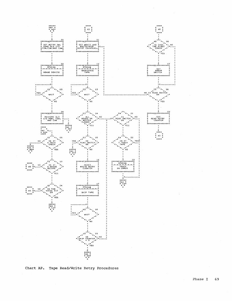
***** *A.P * * A2*
* -
X 01 *****A2**********
* -* SET RETRY Sill. * * SAVE OLD [/0 * *PSIII,CSIII,ANO CA'III*
- * *****************
X 02 *****82** ******** * STDCA\'I * *-*-*-*-*-*-*-*-*
-* SENSE DEV ICE -*****************
••••••••••• X.
• x. C2 *. 03
.* *. .YES .* *.
***4-. . * A3 * • *
11 *****A3********** * * * SET WRITE AND * * WRITE/SKIP *x ••• *RETRY COUNTERS.* • * *****************
12 *****83********** * STOCAW 4-*-*-*-*-*-*-*-*-*
BACKSPACE TAPE
••••••••••• X.
. -.YES .*
.x. C3 *.
*. 13
****
• * * AS * • *
.x. AS *. 06
.* *. .* IS THIS *. NO *. THE FI RST .* .... *. ERROR .* *. .{I-
* •• * * YES
X 07 *****85********** * •
SET ERROR
SWITCH
. .
.X •••••••••••
.x • CS *. 06
.* * • NO IS READ SWITCH
...• *. \\IAI T .* .... *. WAIT *. . . • •.............................. *. ON .*
*. .* *. .*
* •• * * NO
X 04 *****02********** - -* RESTORE OLD *
*. .* *. .*
* •• * - NO
.X. .*. 03 *. 14 04 *. 21
• * *. .* *. .* ALL *. NO .* IS *. NO * [/C PSW. CSW, * •••. * AND CAW *
*. READS OR .* ••.•. ... x*. READ SWITCH .* .•.• *. WRITES.* X *. ON .*
*AP * ••. * E2* **** • x.
E2 *. 05 .* *.
NO.* IS IT *. •••••••• *. A DATA .* X *. CHECK .*
***** *AO * **8~*
*. .* * •• * * YES
.x. F2 *. 10
**** .* *. * NO.* [S IT *. * AS *X •••• *. A NOISE .* *. RECORD .*
*. .* * •• * * YES
.x. G2 *. 24
.* *. NO.* [5 THE *.
* AS *X •••• *. NOISE E!IT .* * * *. ON .* *. .*
*. • * * YES
***** *AO * 4- C2*
* -
*.MADE .* it..* * •• * * •• *
***** *AO * * AS*
* YES * YES
- * • x •
E3 * .. 15 . - * • YES.* IS *. .•. *. READ SWITCH .*
*. ON .* *. .*
* •• * ***** *AO * * 85*
* NO
• *
16 *****F 3**********
* -RESET WRITE RETRY
COUNTER
X 17 *****G3********** * STOCAW * *-*-*-*-*-*-*-*-*
SKIP TAPE
••••••••••• x.
.x. H3 *. 18
• • * * • • YES .* * . •••• *. \'IAIT .*
*. .* *. .*
* •• * * NO
.x. J3 *. 19
.* * • • * IS *. NO • *.SKIP COUNTER .* ••••••
*. :;: 0 .* *. .*
* •• * * YES
, x ***** *AO * * 85* * -.
.x • E4 *. 22
*. • .* .- IS IT *. YESX *. 7 TRACK .* ••..
*. TAPE .* *. .* * •• * * NO
23 *****F4********** * STOCAIII * *-*-*-*-*-*-*-*-* * TRACK *
IN ERROR
. . • X •••• • -...... . X
***** *AO * * C2*
Chart AP. Tape Read/Write Retry Procedures
*. .* * •• * * YES
X 09 *****05********** . . * SET * READ RETRY
COUNTER . *****************
* -* A3 * • *
Phase I 69

SECTION 1: INTRODUCTION
The major functions of Phase II of the Assembler Program are as follows:
Translate Intermediate Text into Machine Language
The Intermediate Text, which contains the partially translated source statements developed by Phase I, are translated into machine-language statements which make up the object program.
The symbols contained in statements are replaced with machine addresses which can now from the Symbol Table developed
the source the actual
be obtained by Phase Ie
The type of translation that occurs depends upon the ID-Code in the Intermediate Text and upon the instruction format.
The operand field, part Text, is translated and output buffer area to be card or written on tape, line in the object program
of Intermediate placed in the
punched into a and printed as a listing.
The translation of each instruction format type is shown in Section 5, "Intermediate Text Translation." The subroutines used by Phase II to translate the Intermediate Text are discussed in Section 3, "Subroutine Description."
Produce Output Cards
The assembler produces three types of cards or card images on tape to be loaded as part of the object program. They are the ESD (External Symbol Dictionary), RLD (Relocation List Dictionary), and TXT (Text) cards. The format for each type of card is shown in Figure 10 at the end of this discussion.
The ESD cards are produced at the beginning of Phase II processing. One ESD card is punched for each START, EXTRN, and ENTRY Assembler instruction.
The TXT cards are produced during Phase II processing. When an output buffer entry becomes full, one text card is punched.
PHASE II
Each TXT card may contain the text from several source statements.
The RLD cards are produced at the end of Phase II processing. The RLD cards are punched from the RLD Table (see Section 2, "Tables"). RLD cards are produced for each relocatable address constant and Channel Command Word defined in the source program.
ESD and RLD Cards: The ESD cards are produced to provide complete linkage between separate program segments. The RLD cards are produced to allow the Relocating Loader to reevaluate symbols and expressions within address constants and Channel Command Words in relocated segments. (For a description of the Relocating Loader, see IBM System/360 Basic Programming Support Basic Utilities, Form No. C28-6505.)
These cards become input to the Relocating Loader, which in turn creates an External Symbol Identification Table (ESID) and a Reference Table to provide communication between the ESD's and RLD'S of various program segments. Collectively, the RLD's and ESDs are called the Control Dictionary.
When a START statement was encountered by the assembler, Phase I assigned the symbol in the statement the identifying number 1, which is entered into the Reference Table by the loader, along with the program segments relocation factor (the difference between the address where the segment was a$sembled and the address where it is loaded). Identifying number 1 was also assigned to the symbols appearing in the operands of all ENTRY statements in that assembly.
For EXTRN statements, the assembler assigned each external symbol an identifying number ranging from 2 through 15, indicating the order in which the EXTRN Assembler instructions were found in the source program. This number is placed in one of the Control Dictionary tables by the loader, along with a pOinter to the Reference Table which includes the external symbol and its actual address (inserted from START and ENTRY ESD cards in other program segments). This allows the loader to implement cross-referencing.
The identifying number associated with the external symbol also appears in the RLD cards produced by the assembler. This allows address constants with either internal or external symbols to be properly evaluated.
Phase II 71

TXT Cards: The object text to be loaded by the loader appears on the text cards. The TXT cards will contain a maximum of 56 bytes of information (columns 17-72) • Therefore, each TXT card may contain the text from several source program statements. If less than 56 bytes are specified for one TXT card, the remaining columns of
, the card are blank.
The text is produced in the order in which it is declared by the source program. TXT cards, therefore, are not necessarily in order by origin (tentative loading address). For example, an ORG statement may cause the program to skip a block of addresses and later in the source program these .addresses may be referenced by another ORG statement •.
A TXT card is terminated and a new one begun whenever there is a break in the string of specified storage content (boundary alignment excluded), whenever a total of 56 bytes of continuous text has been accumulated, or whenever a DC Assembler instruction with a duplication factor is encountered. An ORG statement, whether it results in a change of location counter value or not, is considered to be a break in the string of specified storage content. Any DS Assemhler instruction (except orie with zero length and no boundary alignment needed) is also considered to be a break.
Boundary alignment caused by an instruction being coded at an odd byte boundary, a CNOP coded at an odd byte boundary, a DC Assembler instruction without a duplication factor, or a CCW Assembler instruc.tion, will not cause a new TXT card to be started. Instead, zeros will be inserted into the bytes that are skipped to perform the alignment.
A DC instruction with a duplication factor will cause a new TXT card to be produced after the necessary alignment is done. The new TXT card, and those following, will contain a multiple of the bytes that are to be repeated for as long as the bytes fit on the card, or until all desired data is put on cards. The last card, whether full or not, will not be used for any other text. The text developed from the ·statement following the DC statement will be put on the following card.
For example, the source statement DC 5CL16 1 A" will produce the following cards:
r-------T-----T~----T--~--T----~l
Card 1 ~1 16117-32133-48149-64165-801 I Control I I I I I I infor- I I I I I lmation IA IA IA I I l_~ _____ L-~ __ ~ _____ ~ _____ ~ _____ J
72
r------~T-----T-----T-----------, Card 2 11 16117-32133-48149 80 1
I Control I I I I linfor- I I I I Imation IA IA I I l _______ ~ _____ ~ _____ ~ ___________ J
r-------~----------------T-----' Card 3 11 16117 721 73-8 0 1
I Control I Text from the I I linfor- I following state-I I Imation I ments I I L _______ L-________________ ~ _____ J
Card Formats: The formats of the different types of cards produced Assembler Program are The ESD and TXT card explanatory. The RLD described in detail in follows.
by Phase II of the shown in Figure 10. formats are self-card format is
the discussion that
The position header, which is two bytes long, is the relocatability attribute (external symbol identification) aSSigned by tqe assembler to .the program segment in which the constant is being defined.
The relocation header, which is two bytes long, is the relocatability attribute that was assigneQ to the address symbol when it was defined in the operand field of
. an EXTRN Assembler instruction. It is the same as the external symbol identification assigned to the symbol in Phase I.
The address is the value of the relative assembled address of the relocatable constant within the program segment indicated by the position header. In the case of a CCW,' the address constant is the value of the location counter plus one. This address points to the second field of a CCW.
All RLD"s with the same position and relocation headers will be grouped, in the order found, into one card image.
The flags are as follows:
1. Complement Flag - this one-bit flag indicates to the loader whether the relocation constant for the program segment indicated by the relocation header need be added or· subtracted from the address constant.
2. Continuation Flag - a 1 indicates that more addresses with this relocation and position header are on this. card; a 0 indicates that this is the last address with this relocation and position header (another relocation and position header could follow on this card). This flag occupies one bit.
3. Size - this two-bit flag indicates the size of the symbol (10 - three bytes; 11 - four bytes) •

EXTRNt-2 r--T-----T-----T-----T-----T-----T----------------T-----T--T-------T--------------------, I 112 3 415 -10111 12113 14115 16117 - 22123-24125126 - 28129 - 801 ~--+-----+-----+-----+-----+-----+-.---------------+-~--+--+-------+------------------:...-1 1121 I I I I I Symbol I I I Address I I I 21 E S D II 1 6 I I ESID I from I I 21 6f I Blank I I 91 I I I I no. I operand I I Isymbol I I L __ ~ _____ ~ _____ ~ _____ ~ _____ ~ _____ ~ ________________ ~ ____ ~~--~-------~--------------------J
ENTRy1-2 r--T-----T-----:-T-----T-----------T----------------T-----T--T-------T-----T-----T--------, I 112 3 415 -10111 12113 14 15 16117 22123-24125126 - 28129 3013132133 - 801 ~--+-----+-----+-----+----------_:_+----------------+-----+--+-------+-----+-----+--------1 1121 1 II I ,Symbol I I IAddressl I II I 21 E S D I I 1 6 I I from 1 I 1 I of I I ESID I Blank 1 I 91 I I I I operand I I Isymbol 1 I no. I 1 L __ ~ _____ ~ _____ ~ _____ ~ ___________ ~ ________________ ~ _____ ~ __ ~ _______ ~ _____ ~ _____ i~ _______ J
START'-2 r--T-----T-----T-----T-----T-----T----------------T-----T--r-------T--T--------T--------, 1 112 3 415 -10111 12113 14115 16117 22123-24125126 - 28129130 31 32133 - 801 ~--+-----+-----+-----+-----+-----+----------------+-----+--+-------+--+--------+--------.1 11.21 I I I I I Symbol 1 I I Address I I No. of I I I 21E S DI I 1 6 I IESID I from I I 01 of I Ibytes inl Blank I I 91 I I I I no. 1 operand I I Isymbol I Iprogram I I L __ i _____ i_ ____ i _____ ~ _____ ~ _____ ~ ________________ ~ _____ i __ L~ ______ L __ L ________ i ________ J
ENDG r--T------T-T-----------T-----T-----T-~--------------------------~-~--------------------, I 112 3 4 1516 819 -14115 16117 801 F--+-:----:---+-+-----------t-----+-----+-------------..;.------,--------'------------------------1 I 121 I I Blank or I I I 1 I 21 END I I address to I I ESID I Blank I I 91 I Itransfer tol I no. 1 I L __ i ______ ~_~ ___________ i_ ____ i _____ i ____________ ~ ______________________________________ J
TEXT 1
r--T-----T-T-----T----T-----T-----T-----T------:------------------------~---------T-------, 1112 341516-819 10111 12113 14115 16117 . 72173 -801 ~--+-----+-+-----+----+-----+-----t-----+---------------------------------------+-------1 1121 I I I I Bytes I I I Text 1 I I 21T X TI Istartl I on I IESID I (one byte per column) I Blank I I 9 I I I Addr. I I card I I no. I I I L __ ~ _____ i_i _____ ~ ____ L_ ____ ~ _____ ~ _____ ~ _______________________________________ L_ ______ J
RLDG-3
r--T-----T-----T-----T-----------T-----------T--T-------T--T-------T------------T-------, I 112 3 415 -10111 12113 14 15 16117 20121122 - 24125126 - 28129 72173 - 801 ~--+-----+-----+-----+-----------+-----------+--+-------+--+-------+------------+-----1 I I I I I I IF I IF I I I I 1121 I I Bytes I I Position IL I IL I I I I I 21R L DI I on I land Reloca-IA IAddresslA I Address I (see note 3) 1 Blank I 1 91 I I card I I tion hdrs. I Gil Gil I I I I I I 1 I IS I IS I I I I L __ i~ ____ i _____ i _____ ~ ___________ ~ ___________ ~ __ ~ _______ L__~ _______ ~ _________ ---~-------J
r---------------------------------------------------------------------------------------, I t All cards are produced in extended card code. It will be necessary to convert these I I records from extended card code to get the hexadecimal values. I I 2 Columns 11 and 12 on the ESD cards will contain extended card code punches I I 12-0-1-8-9 and 12-11-1-8-9, respectively (decimal 16). I I 3 These bytes are the same as bytes 21-24 and 25-28 until new position and relocation I 1 headers are required. Then bytes 17-20 will be repeated with the new values. 1 L _________ :... _____________________________________________________________________________ J
Figure 10. Output Formats
Phase II 73

Produce Object Program Listing at location 80 (specified by the START Assembler instruction), the line on the object program listing would appear as indicated in Figure 11, part C. If the statement contained an error, the error flags would be printed to the left of the location counter.
The object program listing produced by Phase II has the format shown in Figure 11, part B. The only exception will be comments statements, which are reproduced on the listing exactly as the source program statements appear.
For example, if the first statement of a program is as shown in Figure 11, part A, and the program is to be assembled starting
Although the source program statement will produce one line of listing, several source statements may be reproduced on a TXT card, as indicated in the previous discussion.
r---------------------------------------------------------------------------------------,
r------------------------------------------------------------, 1 Name 1 Operation 1 Operand 1 Comments 1 ID-Seq. 1 1------------------------------------------------------------1 1 SETBAS 1 BALR 1 14,0 1 LOAD BASE REG 14 1 1080 1 L ____________________________________________________________ J
A. Input Statement
r---------------------------------------------------------, 1 ERROR 1 LOCATION 1 ASSEMBLED MACHINE 1 SOURCE PROGRAM 1 1 FLAGS 1 COUNTER 1 LANGUAGE STATEMENT 1 STATEMENT 1 L ______________________________________ ~--------------____ J
B. Listing Format
r---------------------------------------------------------------, 1 000080 05 EO SETBAS BALR 14,0 LOAD BASE REG 14 00001080 1 L _______________________________________________________________ J
C. Print Line
1 1 1 1 1
1 1 L _______________________________________________________________________________________ J
Figure 11. Object Program Listing Example
74

SECTION 2: TABLES
REGISTER TABLE
The Register Table contains the general register numbers, their corresponding values, and relocatable attributes. An entry is made into this table each time a USING Assembler instruction is encountered. An entry will be deleted from the table each time a DROP Assembler instruction is encountered or when a USING statement uses a previously entered register.
Note: Using Register zero will Register zero with an absolute Register zero is placed into the the assembler and remains in the
not drop attribute. table by
table.
The Register Table is referenced whenever it becomes necessary for the assembler to compute addresses (i.e., assign base registers and displacements) •
The values assigned to the registers are relocatable.
Each entry in the single 32-bit word and configuration:
table occupies a has the following
r------T---------------------------T------, I I I I I RELA I VALUE I REG I L ______ i ___________________________ i ______ J
4 bits 24 bits 4 bits
where:
RELA indicates the relocatability value (0-15)
VALUE is the value of the ·expression in the operand field of the USING statement
REG indicates the general register that is assigned the above value
RELOCATION LIST DICTIONARY (RLD) TABLE
The RLD Table is constructed to hold the data necessary for producing RLD cards or tape records at the conclusion of Phase II processing (see Introduction to Phase II for description of the RLD cards) •
Entries are.made into the RLD Table for three- or four-byte relocatable address constants and Channel Command Words. Each entry in the RLD Table occupies a single 32-bit word and has the following configuration:
r----------T-----~---T-------T-T----------, I 0-3 I 4-5 I 6 171 8-31 I ~----------+---------+---~---+-+----------1 I I I I I I I Relocation I Size IComple-1 I Address 1 I header I indicator I ment 10 1 pointer 1 1 I . 1 flag I I I I I I I I I L __________ i _________ i _______ i_i __________ J
Each of these entries is discussed in the Phase II Introduction under, the RLD card.
At the end of Phase II, the RLD Table is scanned, and the entries having the same position and relocation headers are grouped ihto a' single card image for producing an RLD card or tape record. Error flag K is indicated on all address constants and Channel Command Words in excess of the number allowed for the RLD Table.
Phase II 75

SECTION 3: SUBROUTINE DESCRIPTION
This section describes the subroutines of the Assembler Program that are used during Phase II processing.
SER ~ Simple Expression Translation Routine
The SER subroutine is used to translate a field in the Intermediate Text that contains a simple expression (i.e.; the R1 field of an RR format machine instruction, the operand field of a DROP Assembler instruction, etc.), and to translate each term of a compound expression.
This subroutine is entered with the following parameters, which are set by the calling routine:
COL indicates the first column of the Intermediate Text to be scanned,
LGH
TXT
indicates the fields used in area,
number of four-bit the output buffer
indicates the rightmost bit in output buffer area into which translated expressions are to placed,
the the
be
NBT indicates the number of bytes of input to be translated.
After the field is translated, the output parameter RELA will be set to indicate whether the expression is absolute or relocatable. RELA will have one of the following values:
o 1-15
the expression is absolute, the expression is relocatable.
The field of the Intermediate Text indicated by the above parameters is checked for a self-defining value or a symbol. (Fields 1, 3, and 4 of a CCW instruction are checked for absolute values. If one of the fields is not absolute, error flag R is placed in the print buffer and the entire output area for the CCW is reset to zeros.) Depending upon the value, one of the following procedures plus the Common procedure is followed.
SYMBOL: If the value is a symbol (P bit of the Intermediate Text a 1), the defined bit of the Symbol Table entry is checked. If the symbol is undefined, the procedures described under Undefined are followed. If the symbol is defined, the procedures described under Defined are followed.
76
Undefined: Error flag U is placed in the print buffer. One of the following procedures is then followed, depending upon the instruction type. For instruction types not indicated, no further action is taken and control is returned to the calling routine.
Machine Instruction: The operand field of the output area is set to zero. The operation code remains unchanged. Control is returned to the Phase II Control Routine.
CCW or DC Assembler entire output area for the set to zero. Control is Phase II Control Routine.
Instruction: The instruction is returned to the
DROP, USING, EXTRN, or ENTRY Assembler Instruction: Error flag N is placed in the print buffer along with error flag U. Only the source statement and the error flags will be printed. Control is returned to the Phase II Control Routine.
Defined: tability temporary described
The symbol value and attribute (RELA) are output area, and the under Common are then
the relocaplaced in a
procedures followed.
SELF-DEFINING VALUE: RELA is set to zero since a self-defining value is absolute, and the absolute value is placed in a temporary output area. The procedures described under Common are then followed.
COMMON: If the translation of the field is not complete (parameter TXT not equal to zero), control is returned to the calling routine. If the translation is complete ~XT equal to zero), the output buffer is
Checked to see if the value will fit into the buffer.
If the value will fit, it is stored in the output buffer by subroutine STXT, and control is returned to the calling routine.
Note: If the value is the L field of an SS format instruction, the value is reduced by one before it is stored. Lwith a value of zero is processed the same as an L field with a value of one. The value of zero is not reduced.
If the value will not fit, error flag T is placed in the print buffer, and one of the following procedures is used.
Machine Instruction: If the value is a D1 or D2 field and is absolute, the value is truncated and stored in the output buffer. For all other fields, the operand field of the output buffer for this instruction is set to zero. The operation code, however, remains unchanged. Control is returned to the Phase II Control Routine.

CCW Assembler Instruction: The entire output buffer for this instruction is set to zero and control is returned to the Phase II Control Routine.
USING and DROP Assembler Instructions: The entire statement is ignored and control is returned to the Phase II Control Routine.
Other Assembler Instructions: The translated value is truncated and then stored in the output buffer by subroutine STXT. Control is returned to the calling routine.
When control is returned to the Phase II Control Routine by subroutine SER, the remaining fields of the Intermediate Text for that instruction, if any, are not translated.
EER - Compound Expression Translation Routine
This subroutine is used to translate the fields of the Intermediate Text that may contain a compound expression (i.e., D2 field of a machine instruction, second expression of a CCW Assembler instruction, etc.). The parameters set by the calling routine are the same parameters that are set for the SER subroutine (see preceding discussion) •
The compound expression may contain a maximum of three terms. Each term is translated by subroutine SER. After each term has been translated, several tests are made to determine the validity of the terms.
The following conditions must be met:
1. If one relocatable term is used, it cannot be preceded by a minus (-) sign.
2. If two relocatable terms are used, one of the two terms must be minus (-), and the value of RELA for both terms must be equal.
3. If three relocatable terms are used, there may be only one minus (-) sign, and the value of RELA for all three terms must be equal.
4. If the sign of a term is multiply (*), the terms preceding and following the sign must be absolute.
If these conditions are met, the procedures described under Common are followed.
If these conditions are not met, one of the following procedures is used, depending upon the instruction type. Only the instructions that may have a compound expression in the operand field are indicated.
Machine Instruction, CCW or DC Type A Assembler Instruction: Error flag A is placed in the print buffer, the output buffer for the instruction is set to zero (the operation code remains unchanged for a
machine instruction), and control is returned to the Phase II Control Routine.
USING Assembler Instruction: Error flags A and N are placed in the print buffer. Only the source statement and the error flags are printed in the object program listing. Control is returned to the Phase II Control Routine.
END Assembler Instruction: Error flag A is placed in the print buffer, and control is returned to the calling routine.
COMMON: The value of RELA is relocatability attribute of and the terms are combined their signs. The result temporary save area.
set to the the symbols,
according to is stored in a
The only negative answer that is allowed is for a DC type A instruction with a RELA value of zero. If the answer is negative for any other instruction type, or RELA is not zero for a DC type A, error flag Y is placed in the print buffer.
If the answer is positive, or after error flag Yis placed in the print buffer, one of the following procedures is used.
Machine Instructions: If a base register is not indicated, the values of the base register and displacement are obtained from the Register Table by subroutine ~~S and stored in the output buffer. Control is then returned to the calling routine.
If a base register is indicated, the value of the displacement should be absolute. If it is not, error flag R is placed in the print buffer before the displacement is tested to see if it is equal to, or less than, 4095, the maximum value allowed.
If the displacement is too large, error flag T is placed in the print buffer, the value is truncated and stored in the output buffer by subroutine STXT, and control is returned to the calling routine.
If the displacement is correct, the value of the combined terms is stored in the output buffer, subroutine SER is entered to translate the base register field, and control is returned to the calling routine.
Assembler Instructions: The value of the combined terms is placed in the output buffer by subroutine STXT, and control is returned to the calling routine.
Phase II 77
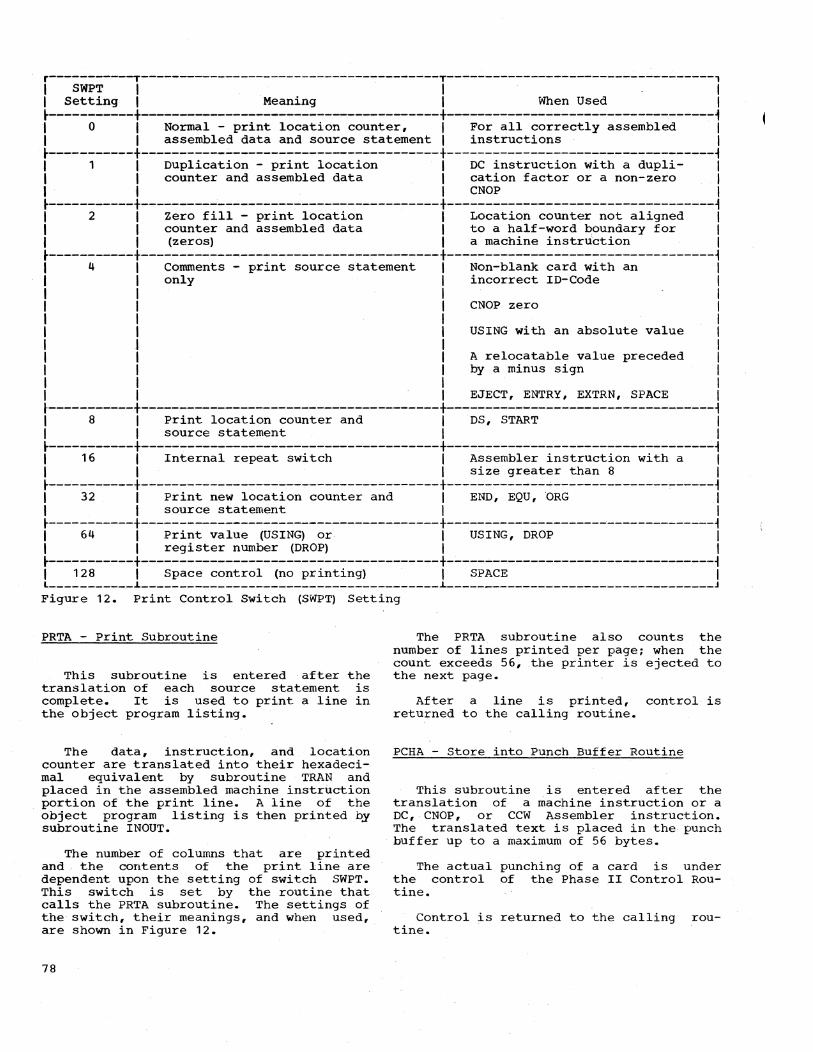
r-----------T---------------------------------------T-----------------------------------, I SWPT I I I I Setting I Meaning I When Used I
~-----------+--------------------------~------------+-------------------------------~---~ I 0 I Normal - print location counter, I For all correctly assembled I I I assembled data and source statement I instructions I ~-----------+---------------------------------------+-----------------------------------~ I 1 I Duplication - print location I DC instruction with a dupli- I I I counter and assembled data I cation factor or a non-zero I I I I CNOP I ~-----------+---------------------------------------+-----------------------------------~ I 2 I Zero fill - print location I Location counter not aligned I I I counter and assembled data I to a half-word boundary for I I I (zeros) I a machine instruction I ~-----------+---------------------------------------+-----------------------------------~ I 4 I Comments - print source statement I Non-blank card with an I I I only I incorrect ID-Code I I I I I I I I CNOP zero I I I I I I I I USING with an absolute value I I I I I I I I A relocatable value preceded I I I I by a minus sign I I I I I I I I EJECT, ENTRY, EXTRN, SPACE I .-----------+---------------------------------------+-----------------------------------~ I 8 I print location counter and I DS, START I I I source statement I I ~-----------+---------------------------------------+-----------------------------------~ I 16 I Internal repeat switch I Assembler instruction with a I I I I size greater than 8 I ~-----------+---------------------~-----------------+-------------~---------------------~ I 32 I Print new location counter and I END, EQU,ORG I I I source statement I I ~-----------+---------------------------------------+--------------------~--------------~ I 64 I Print value (USING) or I USING, DROP I I I register number (DROP) I I ~-----------+---------------------------------------+-----------------------------------~ I 128 I Space control (no printing) I SPACE I L ___________ ~ _______________________________________ ~ ___________________________________ J
Figure 12. Print Control Switch (SWPT) Setting
PRTA - print Subroutine
This subroutine is entered after the translation of each source statement is complete. It is used to print a line in the object program listing.
The data, instruction, and location counter are translated into their hexadecimal equivalent by subroutine TRAN and placed in the assembled machine instruction portion of the print line. A line of the object program listing is then printed by subroutine INOUT.
The number of columns that are printed and the contents of the print line are dependent upon the setting of switch SWPT. This switch is set by the routine that calls the PRTA subroutine. The settings of the switch, their meanings, and when used, are shown in Figure 12.
78
The PRTA subroutine also counts the number of lines printed per page; when the count exceeds 56, the printer is ejected to the next page.
After a line is printed, control is returned to the calling routine.
PCHA - Store into Punch Buffer Routine
This subroutine is entered after the translation of a machine instruction or a DC, CNOP, or CCW Assembler instruction. The translated text is placed in the punch buffer up to a maximum of 56 bytes.
The actual punching of a card is under the control of the Phase II Control Routine.
Control is returned to the calling routine.
Punch RLD and END Cards Routine
This subroutine is entered after the END statement has been processed.
The RLD Table is searched, and all RLD's with the same position header are grouped into one card image (or until a card is full) and produced. (See Phase II Introduction for RLD card layout and Section 2, "Tables," for a description of the RLD Table.)
After the RLD cards are produced, the END card format is punched, and the program halts.
If the output is tape, an 'LOT' record is written on the tape after the 'END' record. The tape is then backspaced over the LDT record, so that in a stacked assembly all LDT records but that following the last object program are overwritten.
DOUT - Punch TXT Cards Routine
This subroutine is entered from the Phase II Control Routine whenever enough data to fill an output buffer has been accumulated, and, if it is a card system, when a blank card is available.
The necessary control information is placed in the card image along with the translated text. (See Introduction to Phase II for TXT card layout, Figure 10.) The card image is then punched or written on tape, depending upon the system being used.
Control is returned to the Phase II Control Routine except when the output buffer is emptied after the END card ~s read. Control is then transferred to output RLD and END cards (see preceding discussion) •
FERR - Store Error Flags Routine
The FERR subroutine places the necessary error flags in the print buffer. These flags are those placed in the Intermediate Text by Phase I and the flags for the errors encountered during Phase II processing.
The following error fiags may be placed in the print buffer by Phase II:
r-----T-----------------------------------, ,Flag , Meaning , ~-----+-----------------------------------~
I ,Expression cannot be mapped into , a base register and displacement ,
K 'RLD Table full , U ,Undefined symbol , W I Unused mask bits in CCW instruc
I tion not zero I
X ,Duplicate ENTRY statement , Y I Illegal negative expression in
, operand field l _____ i __________________________________ _
NOte: See ·Phase I", Section 3, Subroutine Description, subroutine ERR for Phase I error flags and flags common to both phases.
INOUT - Input/Output Subroutine
This subroutine is the same subroutine used by Phase I. Refer to "Phase I," Section 3,' "Subroutine Descriptions."
Phase II 79

SECTION 4: PHASE II PROCESSING FLOW
This section uses two charts to describe the overall processing flow of Phase II of the Assembler Program. Chart 06 illustrates the initialization procedures, and Chart 07 illustrates the Control Routine. The numbers in parentheses within the text describing each chart indicate the block on the chart being explained.
INITIALIZATION - CHART 06
Phase II of the Assembler Program is read into main storage. The new PSW's are loaded into. main storage, and the print buffer is set to blanks (01). The type of input is then checked (03) • The printer is ejected to a new page and a heading is printed.
If the input control indicates that Phase I assembled on tape, the tape unit is selected, the read parameter is set to read 104 bytes (one input record on tape) , and the input tape unit is rewound (04-05). A card image is then read from tape (06), and control is transferred to complete the
'initialization processing (09).
If the input control indicates that Phase I assembled on cards, the first card is read and checked (06-07). If the card is a Symbol Table card, the rest of the Symbol Table deck is read into the area of main storage reserved for the Symbol Table (10). The Symbol Table deck will not be included when Phase I assembled on tape (Phase II must immediately follow Phase I) , or when Phase II immediately follows Phase I in a card assembly, because the Symbol Table will still be in storage.
The type of object output is checked, i.e., tape or card (09.1) , and the appropriate parameters for the output are modified (13,15) and control is then transferred to location C811 in the Control Routine (Chart 07, block 07) (05-06).
A test is made to determine what type of printing device is on line. One of the following then occurs:
1. If the off-line printing option is used, the parameters for off-line printing are modified (16).
2. If both a printer (1443/1403) and a typewriter (1052) are available, no modifications are 'made.
3. If the printer is used as a typewriter, all warning messages will be listed on the printer. However, if the programmer uses the no-print option,
80
these warning messages will not be printed but will only be displayed in the I.C. lights on the console.
4. If the typewriter is used as a printer, modifications are made so that an EJECT instruction will be processed as a SPACE 6 instruction.
5. If no device is available, all printing is inhibited (including error flags) •
The RLD Table is set up according to the size of main storage, the number of output buffers is determined, and the header for each is cleared (08). The number of buffers is determined by dividing the unused main storage into 64~byte fields. This number is then placed in locations NOPB (number of output buffers) and NBL (number
of buffers left) for later use in the processing routine.
The first output buffer is set up to contain a START format with a blank program name and a starting location of zero. This is done to guard against the possibility of a programmer not specifying a START, without which the object program is not relocatable. If the program contains a START statement it will overlay the pseudo-start.
CONTROL ROUTINE - CHART 07
Note: The discussion of the Control Routine starts at location C811 (07) since this is the initial entry point from the initialization routine.
General
The card image, when the 1qq2 card read-punch unit is used, is checked for a blank. If the card is blank, the output buffer area is checked to determine if enough information has been processed to fill an object program card or card image on tape (8). If not, the blank card is ignored and control is transferred to location C819 (10) for further testing. If an output buffer is full, an object program card is produced by subroutine DOUT (09) before control is transferred to location C819 (10).
If the card is not blank (07), or the object program card has been produced (09), the ID-Code of the Intermediate Text is checked (10-14).
If the ID-Code is B or K (10), indicating an Assembler instru~tion, control is transferred to location C827 to determine

which Assembler instruction is to be processed (byte 2 of the Intermediate Text is checke~ , and control is transferred to the routine necessary to translate that instruction (see section 5, "Intermediate Text Translation"). The return to the Control Routine varies with the type of instruction and is shown in Section 5.
If the card was blank (11), as it would have been if an object program card had just been produced, control is transferred to location CS04 (01) to set up for processing the next statement.
If theID-Code is A, J or M (12), indicating a machine instruction or error type M, control is transferred to location CS231 (20) to translate the machine instruction (see Machine Instruction Processing section) •
If the ID-Code is L or C (14), indicat-ing the instruction is not to be assembled (~ or it is a comments statement (C), control is transferred to location CS25 (16) 'to list the card in the object program listing (see Common section) •
If the card does not contain a correct ID-Code or is not blank, error flag N is placed in the print buffer (15) by subroutine FERR before control is transfer.red to the print routine (16) (see Common section) •
Common
After the above procedures, or after the translation of the instruction is completed correctly, subroutine PRTA is entered to store the data in the print buffer and to list a line of the object program (16). The number of columns to be listed, and the contents of each line, are determined by the procedure followed before entering this subroutine (see Section 3, "Subroutine Descriptions,· subroutine PRTA, for detailed explanation) •
is incremented by The location counter SIZE (number of bytes) of just translated (17). ferred to location C'S04 processing the next statement.
the instruction Control is trans
(01) to set up for intermediate text
Location CS04 (01) will contain a transfer to location FH11 (02) until all START, ENTRY, EXTRN, and ICTL Assembler instructions have been translated.
The statement just processed is checked (02-03), and if it is blank, a START,
ENTRY, EXTRN, or ICTL, or contains ID-Code
L or C, control transfers to location DS05 (OS) to prepare for the next intermediate text statement.
If the intermediate text statement is none of the above, control is transferred to location FH12 (04). Location CS04 (01) is changed to a branch to location CSOS, and shared main storage is reset to be used as additional output buffers. NBL and NOPB are incremented accordingly.
Shared main storage is the area of main storage occupied by the initialization routine and the routines necessary to translate the START, ICTL, ENTRY, and EXTRN Assembler instructions.
After shared main storage has been reset, the program switches that affect the processing of each instruction are reset, and the current value of the location counter is stored in the first location of the Syrr~ol Table (05).
The program switches reset after each instruction is processed are:
SIZE
IOCTL
ZBYT
SWPT
RELA
contains the size of the instruction, and controls the incrementing of the location counter, contains the trap and operate switches for the INOUT SUbroutine, is the output byte counter for the PRTA subroutine, controls the printing of a line of the object program by subroutine PRTA, is the relocatability attribute indicator.
After the switches are reset, subroutine INOUT is entered to read the next card or tape record (06). Control is then transferred to location CS11 (07) to start the processing of the statement (see General section) •
Machine Instruction Processing
If this is a type M CCW, control is transferred to location C90S (chart BD) •
If the location counter is not at an even byte (half-word boundary) (lS), control is transferred to location C930 (23).
SIZE, which indicates the number of bytes by which to increment the location counter, is set to a 1. Control is transferred to subroutine SUZ which zeros the output buffer and causes a byte of zeros to be printed. Subroutine PCHA is then entered to store one byte of zeros in the text buffer (24), and the location counter
Phase II Sl

is incremented by SIZE (25). Control is then transferred to translate the machine instruction (19).
If the location counter is on a halfword boundary, or after it is aligned to a half-word boundary, a test is made for a CNOP instruction (19). If this is a CNOP instruction, control is transfe~red to Chart BA to process the instruction. If this is not a CNOP, the operation code (byte 2 of the Intermediate Text) is placed in the output text buffer (20). A test is then made for an ID-Code M machine instruction (21). If the ID-Code is M, control is transferred to location F730 in subroutine SER to reset the text buffer to
82
zeroes. If the ID-Code is not M,the size of the instruction (determined by the operation code) is stored in SIZE (21).
Control is then transferred to translate the instruction according to format (22) and returns to location C824 (27) to store the translated instruction in the punch buffer (27). (See Section 5, "Intermediate Text Translation," for error returns from the specific instruction translation routines.) After the data has been stored in the punch buffer, control is transferred to location C804 (01) to set up for processing the next intermediate text statement (see General section).
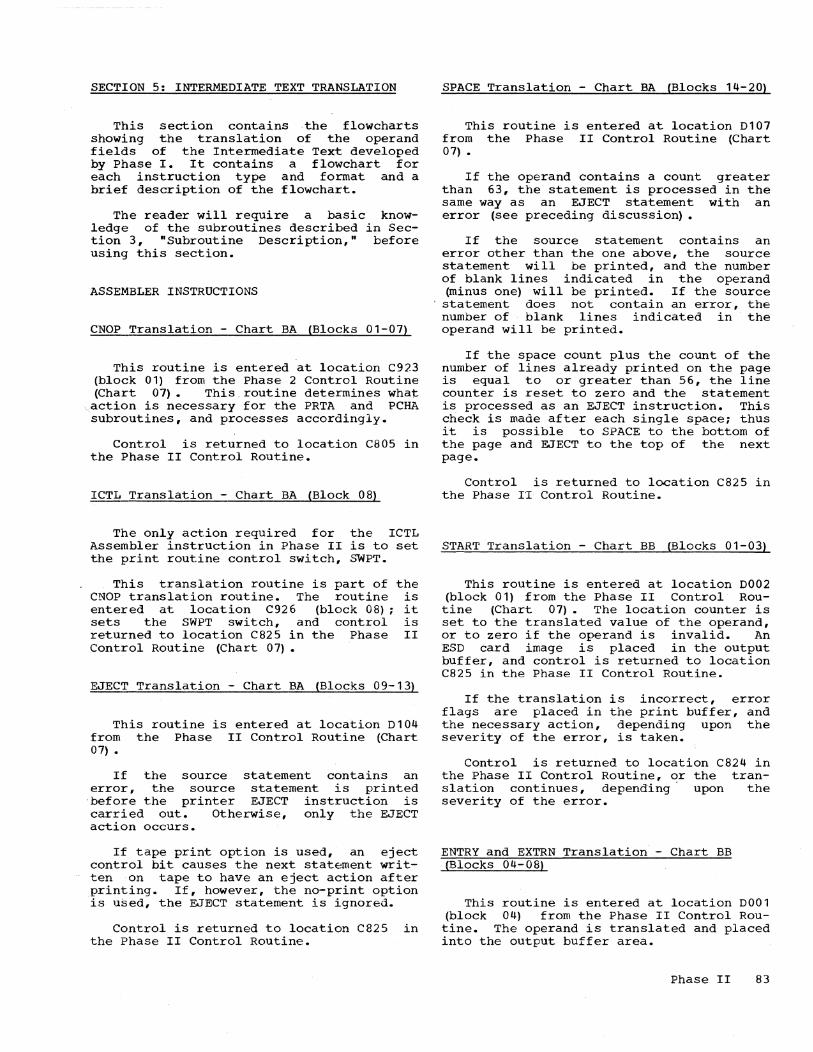
SECTION 5: INTERMEDIATE TEXT TRANSLATION
This section contains the flowcharts showing the translation of the operand fields of the Intermediate Text developed by Phase I. It contains a flowchart for each instruction type and format and a brief description of the flowchart.
The reader will require a basic knowledge of the subroutines described in Section 3, "Subroutine Description," before using this section.
ASSEMBLER INSTRUCTIONS
CNOP Translation - Chart BA (Blocks 01-07)
This routine is entered at location C923 (block 01) from the Phase 2 Control Routine (Chart 07). This routine determines what
,action is necessary for the PRTA and PCHA subroutines, and processes accordingly.
Control is returned to location C805 in the Phase II Control Routine.
ICTL Translation - Chart BA (Block 08)
The only action required for the ICTL Assembler instruction in Phase II is to set the print routine control switch, SWPT.
This translation routine is part of the CNOP translation routine. The routine is entered at location C926 (block 08); it sets the SWPT switch, and control is returned to location C825 in the Phase II Control Routine (Chart 07) •
EJECT Translation - Chart BA (Blocks 09-13)
This routine is entered at location D104 from the Phase II Control Routine (Chart 07) •
If the source statement contains an error, the source statement is printed 'before the printer EJECT instruction is carried out. Otherwise, only the EJECT action occurs.
If tape print option is used, an eject control bit causes the next stat~ment written on tape to have an eject action after printing. If, however, the no-print option is used, the EJECT statement is ignored.
Control is returned to location C825 in the Phase II Control Routine.
SPACE Translation - Chart SA (Blocks 14-20)
This routine is entered at location D107 from the Phase II Control Routine (Chart 07) •
If the operand contains a count greater than 63, the statement is processed in the same way as an EJECT statement with an error (see preceding discussion) •
If the source statement contains an error other than the one above, the source statement will be printed, and the number of blank lines indicated in the operand (minus one) will be printed. If the source
'statement does not contain an error, the number of blank lines indicated in the operand will be printed.
If the space count plus the count of the number of lines already printed on the page is equal to or greater than 56, the line counter is reset to zero and the statement is processed as an EJECT instruction. This check is made after each single space; thus it is possible to SPACE to the bottom of the page and EJECT to the top of the next page.
Control is returned to location C825 in the Phase II Control Routine.
START Translation - Chart BB (Blocks 01-03)
This routine is entered at location D002 (block 01) from the Phase II Control Routine (Chart 07). The location counter is set to the translated value of the operand, or to zero if the operand is invalid. An ESD card image is placed in the output buffer, and control is returned to location C825 in the Phase II Control Routine.
If the translation is incorrect, error flags are placed in the print buffer, and the necessary action, depending upon the severity of the error, is taken.
Control is returned to location C824 in the Phase II Control Routine, or the translation continues, depending' upon the severity of the error.
ENTRY and EXTRN Translation - Chart BB (Blocks 04-08)
This routine is entered at location D001 (block ~4) from the Phase II Control Routine. The operand is translated and placed into the output buffer area.
Phase II 83

If the statement is an EXTRN, card image is placed into the punch and control is returned to location the Phase II Control Routine (Chart
an ESD buffer, C825 in 07) •
If the statement is an ENTRY, the symbol in the operand can be used in one ENTRY statemen~ only. The ESD card image is placed ~n the punch buffer if the symbol has not been used previously. Control is returned to location C825 in the Phase II Control Routine.
If the symbol has been previous~y used, this ENTRY statement is ignored, and an error flag is placed in the output buffer before control is returned to location C825 in the Phase II Control Routine.
If the translation-is incorrect, error flags are placed in the print buffer, and the necessary action, depending upon the severity of the error, is taken.
Control is returned to location C824 in the Phase II Control Routine, or the translation continues, depending upon the severity of the error.
DROP Translation - Chart BB (Blocks 09-13)
This routine is entered at location D140 (block 09) from the Phase II Control Routine (Chart 07). The operand is translated and, if valid, the indicated register is removed from the Register Table.
The source statement is listed, and control is returned to location C804 in the Phase II Control Routine.
If the translation is incorrect, error flags are placed in the print buffer, and the necessary action, depending upon t~e severity of the error, is taken.
Control returns to location C824 in the Phase II Control Routine, or the translation continues, depending upon the severity of the error.
USING Translation - Chart BB (Blocks 14-24)
This routine is entered at location D020 (block 14) from the Phase 1.1 Control Routine (Chart 07). The first expression is translated and placed in the output buffer area.
If the first expression is valid, the second expression is translated and, if valid, the indicated register is entered
.84
into the Register Table. Control returned to location C825 in the Phase Control Routine.
is II
If either translation is incorrect, error flags are placed in the print buffer, and the necessary action, depending upon the severity of the error, is taken.
Control is returned to location C824 in the Phase II Control Routine, or the translati·on continues, depending upon the severity of the error.
END, EQU, and ORG Translation - Chart BC
This routine is entered at (block 01) from the Phase II tine (Chart 07). The operand and, if valid, placed in the area.
location D006 Control Rouis translated output buffer
If the translation is incorrect, error flags are placed in the print buffer., and the necessary action, depending upon the severity of the error, is taken.
Control returns to location C824 in the Phase II Control Routine, or the translation continues, depending upon the severity of the. error.
If the instruction is an EQU, control is returned to location C825 in the Phase II Control Routine.
The source statement is printed, and the output is set to a blank buffer, since an ORG or an END instruction is considered to be a break in the string of specified storage content, and therefore a new output card must be started.
If the statement is an ORG instruction, control is returned to location C804 in the Phase II Control Routine.
If the statement is an END instruction, all remaining output buffers are produced; the RLD cards are produced from the RLD Table (see "Introduction"); the END card is produced; the EOJ message is listed and/or displayed; the processing is ended, and the program stops. If object output is on tape, an LDT record .is written, and then backspaced over so that it will be overwritten if this is a stacked assembly.
DS Translation - Chart BD (Blocks 09-14)
This routine is entered .at location C915 (block 09) from the Phase II Control Routine (Chart 07) •

The location counter is incremented by the number of bytes reserved by the DS instruction. The output is set to a blank buffer, since a DS instruction is considered to be a break in the string of specified storage content, and therefore a new output buffer must be started.
The source statement is printed, and control is returned to location C804 in the Phase II Control Routine.
CCW Translation - Chart BD (Blocks 02-08) and Chart BE (Blocks 15-22)
This routine is entered at location C908 (Chart CF, block 02) from the Phase II
Control Routine (Chart 07) •
The location counter is aligned to a double-word boundary, and the necessary zeros are placed in the output buffer. The location counter is then set to be incremented by eight bytes, the size of the CCW instruction, since the location counter is incremented regardless of errors.
If the ID-Code is M, indicating the instruction is to be assembled as zeros, no further pr9cessing occurs, and control is returned to location C824 in the Phase II Control Routine.
The expressions in the operand are translated and placed in the output buffer area. The translation of the second expression, if valid, will cause an entry into the RLD Table (see "Introduction").
If the translation of any expression is incorrect, error flags are placed in the print buffer, and the necessary action, depending upon the severity of the eIror, is taken.
Control is returned to location C824 in the Phase II Control Routine, or the translation continues, depending upon the severity of the error. If control is returned to the Phase II Control Routine because of an error, the remaining expressions in the statement are not translated.
DC Translation - Chart BD (Blocks 01, 03-06) and Chart BE (Blocks 01-14)
This routine is entered at location C901 (Chart eF, block 01) from the Phase II
Control Routine (Chart 07) •
The aligned
location counter is set to be to the word boundary determined by
the type of DC statement. The number of zeros necessary to accomplish this are placed in the output buffer.
The location counter mented according to the the statement, and one procedures is followed.
is set to be increL (length) field of of the following
DC Type A Instruction: The operand is translated and placed into the output buffer area.
If the translation is invalid, error flags are placed into the print buffer and the necessary action, depending upon the severity of the error, is taken.
Control returns to location C824 in the Phase II Control Routine, or the translation continues, depending upon the severity of the error.
An entry is made into the RLD Table (see "Introduction") if the translated operand is a three- or four-byte value. Control is returned to location C824 in the Phase II Cohtrol Routine.
Other DC Instructions: The constant is placed in the output buffer area and the source statement is listed. The location counter is then incremented by the size of the L field. A line is printed and the location counter is incremented until the duplication factor is equal to zero.
Control is then returned to location C804 in the Phase II Control Routine.
MACHINE INSTRUCTIONS
RR Format Translation - Chart BF (Blocks 01-08)
This routine is a continuation of the machine-instruction translation portion of the Phase II Control Routine starting at location C8201 (Chart 07) •
The operand is translated according to the type of RR format (see "Phase I," Section 5, Chart AH and description) and placed in the output buffer area. Control is returned to location C824 in the Phase II Control Routine.
If the translation is incorrect, error flags are placed in the print buffer, and the necessary action, depending upon the severity of the error, is taken.
Control is returned to location C824 in the Phase II Control Routine, or the tran-
Phase II 85
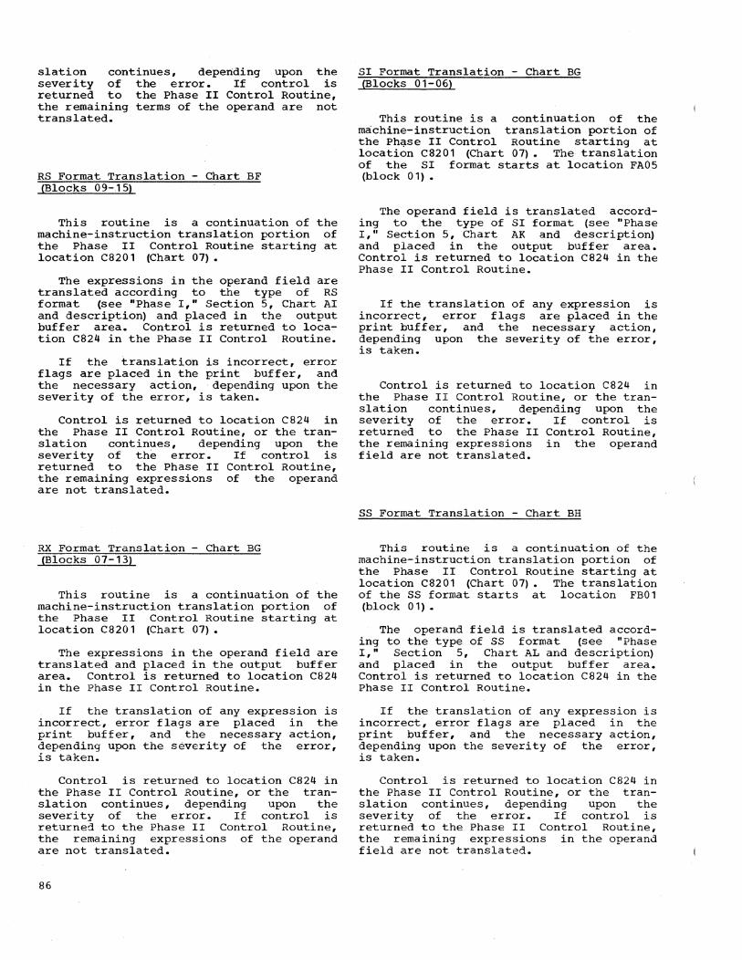
slation continues, depending upon the severity of the error. If control is returned to the Phase II Control Routine, the remaining terms of the operand are not translated.
RS Format Translation - Chart BF (Blocks 09-.1 5)
This routine is a continuation of the machine-instruction translation portion of the Phase II Control Routine starting at location C8201 (Chart 01) •
The expressions in the operand field are translated according to the type of RS format (see "Phase I," Section 5, Chart AI and description) and placed in the output buffer area. Control is returned to location C824 in the Phase II Control Routine.
If the translation is incorrect, error flags are placed in the print buffer, and the necessary action, depending upon the severity of the error, is taken.
Control is returned to location C824 in the Phase II Control Routine, or the translation continues, depending upon the severity of the error. If control is returned to the Phase II Control Routine, the remaining expressions of the operand are not translated.
RX Format Translation - Chart BG (Blocks 01-13)
This routine is .a continuation of the machine-instruction translation portion of the Phase II Control Routine starting at location C8201 (Chart 01) •
The expressions in the operand field are translated and placed in the output buffer area. Control is returned to location C824 in the Phase II Control Routine.
If the translation of any expression is incorrect, error flags are placed in the print buffer, and the necessary action, depending upon the severity of the error, is taken.
Control is returned to location C824 in the Phase II Control Routine, or the translation continues, depending upon the severity of the error. If control is returned to the Phase II Control Routine, the rema1n1ng expressions of the operand are not translated.
86
SI Format Translation - Chart BG (Blocks 01-06)
This routine is a continuation 6f the machine-instruction translation portion of the Ph9se II Control Routine starting at location C8201 (Chart 01). The translation of the SI format starts at location FA05 (block 01) •
The operand field is translated according to the type of SI format (see "Phase I," Section 5, Chart AK and description) and placed in the output buffer area. Control is returned to location C824 in the Phase II Control Routine.
If the translation of any expression is incorrect, error flags are placed in the print buffer, and the necessary action, depending upon the severity of the error, is taken.
Control is returned to location C824 in the Phase II Control Routine, or the translation continues, depending upon the severity of the error. If control is returned to the Phase II Control Routine, the remaining expressions in the operand field are not translated.
SS Format Translation - Chart BH
This routine is a continuation of the machine-instruction translation portion of the Phase II Control Routine starting at location C8201 (Chart 01). The translation of the SS format starts at location FB01 (block 01).
The operand field is translated according to the type of SS format (see "Phase I," Section 5, Chart AL and description) and placed in the output buffer area. Control is returned to location C824 in the Phase II Control Routine.
If the translation of any expression is incorrect, error flags are placed in the print buffer, and the necessary action, depending upon the severity of the error, is taken.
Control is returned to location C824 in the Phase II Control Routine, or the translation continues, depending upon the severity of the error. If control is returned to the Phase II Control Routine, the rema1n1ng expressions in the operand field are not translated.
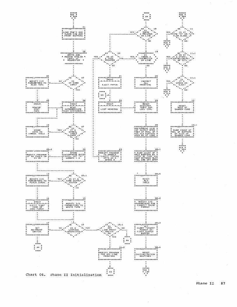
O. *****Cl********** · .
***** *06 * * A2* .. .
X 01 *****A2********** · . *LCAD PSW'S AND * * CLEAR CAW AND * * PRINT BUFFERS * · . *****************
X 02 ******82** *********
WRITE AND * REWIND SYSLIB *
TAPE, [F REQUESTED
• x. C2 *. 03
.* *. * MODIFY I/O * 1\0.* [S *. * PARAMETERS TO *X •••••••• *. IT CARD .* * READ TAPE * *. INPUT .*
* *..* ***************** *. .*
X 05 *****01 **** ****** * INOUT *
* YES
X 06 *****02********** - * INDUr * *-*-*-*-*-*-*-*-*
* · REWIND ITXT TAPE
* •••••••• X* READ
• 10 *****E 1 **** ****** · . STORE
* INTERMEDIATE * *TEXT STATEMENT * *****************
.x. E2 *. 07
• * IS *. YES.* IT A *.
'* DATA IN *X •••••••• *. SYMBOL .* '* SYMBOL TABLE * *. TABLE .* · ****** ***** ******
*.CARD .* *. • * • NO
09.2 09 *****Fl********** *****F2********** * * * STORE * *MODIFY PROGRAM * *INTERPHASE ByrE* *IF NO PUNCH Sill *X •••••••• *{TCD}. SET '*1 * * IS ON * * LENGTH = 6 *
13 .X. *****Gl********** G2 *O' 09.1 * * .* *. * MODIFY [/0 * YES.* IS IT A *. * PARAMETERS TO *X •••••••• *. CARD OUTPUT .* * PUNCH CARDS * *. SYSTEM .*
*. .* ***************** * •• *
I. *****H 1 ********** * [NOLT * *-*-*-*-*-*-*-*-*
EJECT 'END' CARD IF
* 1442 PUNCH * *****************
* ~O
X 15 *****H2********** · . * MODIFY I/O * * PARAMETERS TO * * WRITE TAPE *
. .
.O' •• ~ .......... O' .......... O' ......... X.
. . * A4 * . .
****
• x. A4 *. 18
.* IS *. YES.* THERE *.
•••••••••••••••••• *. A PRINTER .* *. ON LINE .*
*. .* * •• * • NO
.x. 19 B3 *. 20
.* *. YES.* IS IT *. YES *
X **B4*******
[5 THERE A
TYPEWRI TER ON LI NE
•••• *. A 1052 .*X •••••••• * *~ PRINTER .* * *..* *
*.' .* *********** * NO • NO
21 *****(3********** * INOUT * *-*-*-*-*-*-*-*-*
EJECT PAPER
. '. * 03 *.X. . .
.
X 22 *****03********** * INOUT * *-*-*-*-*-*-*-*-*
X 2. *****C4********** · . INHIBIT
ALL PRINTING
X 25 *****04********** ... RESET *
REGISTER TABLE AND .. * •••••••• X*
: LIST HEADING .. * LOC. CTR.
23 **** *F3********** *MOO IFY PROGRAM *
• * TO HANDLE * ••• X*"EJECT' PSEUDO *
* OptS AS A * * SPACE 6 * *****************
08 *****E4********** *DETERMINE SIZE * *OF OUTPUT BFRS * *SET UP MIN. OF * *30 RLD BUFFERS * *PER BK OF CORE * **iI·* ***** ********
08.1 *****F4********** * 8UMP COUNT OF * *RLD BUFFERS BY * *51 ZE OF CORE I N* *GAP 8ETWEEN RLO* *TBL AND OPT BFR* *****************
08.5 **44*G4*4******** · . RESET
RLO TABLE
x 08.2 *****H4********** * MODIFY I/O * *PARAMETERS FOR * * CORRECT PRINT *
FORMAT
17 *****J 1 ********** * •
'.x. .*. x 08.3
SET NO-PRINT
SWITCH
* • * A4 * . .
Chart 06.
J2 *. 16 J3 *. 16.1 .* *. .* IS *.
NC.* IS A *. YES .* OFF *. NO *X •••••••• *. LISTING .* •••••••• X*. LINE PRINT .* •••• * *.REQUESTED.* *. SWITCH O'*
*..* *. ON .* * •• * * •• * * * YES . .
* A4 * . . X 16.2
*****K3********** * * *MODIFY PROGRAM * * FOR OFF LINE * * PRINTING
Phase II Initialization
x **** . .
* 03 * . .
*****J4********** * SET * * DUMMY 'START' * .. FORMAT IN * * FIRST OUTPUT * BUFFER * *********4*******
X 08.4 *****K4********** · . * RESET * *INITIALIZATION * * ROUTINES *
x ***** *e8 * * 19* ..
***** *06 * * AS* . . .x •
AS *. 11 .* *.
YES.* IS IT *. ••• *TYPE 'Co OR 'L'*
*.OR BLANK .* *. .* * •• *
***** * NO *C8 * * 01* · .
.x. 85 *. 11.1
• * I S IT *. YES .* A START. *. ••• *.EXTRN,ENTRY •• *
*. OR ICTL .* *. .* * •• *
***** * NO *C8 * * Dl* · . .
.x. CS *. 11.1
.* IS *. YES.* IT A *. ••• *. SPACE OR .*
***** *e8 * * 01 * · . .
*. EJECT .* *. .*
*. O'* • NO
X 12 *****05********** . .
RESET REST OF
SHARED CORE
X 12.1 *****E5********** . . * SUMP COUNT OF * *NO. OF BUFFERS .. * BY SIZE OF * * SHARED CORE * *****************
x ***** *C8 * .. 05*
Phase II 87

***** *07 * * Al*
**** * * · .. * Al *.X. · . **** ce04 .X.
1\1 *. 01 .* IS *.
C819 .*. C827 A2 *. 10 **********************************
.* *. * ENTER CORRECT ASSEMBLER TRANS. * .* IS *. YES * ROUTINE BY CHECKING BYTe 2 OF * .* THIS A *. YES
*. BRANCH TO .* •••• *. C805 .*
••• X*. IO-CODE .* •••••••• X* INTERMEDIATE TEXT. RETURN OE- * *. .*
* •• * • NO
FHl1 .X. Bl *. 02
• * *. • .* IS IT A *. YES.
*.BLANK, TYPE C.* •• X. *. OR L .*
*. .* * •• * * NO
• x. Cl *. 03 • * 1 S IT *. •
.* A START~ *. YES. *.EXTRN. ENTRY~.* •• X.
*. OR ICTL .* *. .*
* •• * • NO
FI-I12 X 04 *****Dl********** *SET C804 TO BRN* * BUMP NBL AND * *Nopa BY SI ZE OF* *SHARED CORE RE-* *SET SHARED CORE* *****************
· . *07 *.X. * El* .x ••••••••••• **** •
ce05 X '05 *****~l********** * RESET PROGRAM * *SWITCHES. STORE* * C~RRENT VALUE * *OF LOC. CTR. IN* * SYMBOL TABLE * ************._***
X 06 *****Fl********** *INOuT * *-*-*-*-*-*-*-*-* * READ * INTERNEDI ATE .. TEXT * *****************
.'
*. B OR K .* * PENDS UPON INSTRUCTION TYPE. * *..* ******************.**** •• *********
* •• * * INSTR •• LOC. ** INSTR •• LOC. * * NO * ••••••••••••••• ** ••••••••••••••• * * ccw • BOB2 ** eau • BCBl * * ••••••••••••••• ** ••••••••••••••• * * CNOP • 07C4 ** EXTRN • BBB2 * * ••••••••••••••• ** ••••••••••••••• * * DC • BDBI ** ICTL • BAC2 *
.x. * ••••••••••••••• ** ••••••••••••••• * B2 *. 11 * DROP • 88Gl ** ORG • BC81 *
.* * • * ••••••••••••••• ** ••••••••••••••• * .* IS *. YES *. ID-CODE .* •••• *. BLANK .* * OS • 8084 ** SPACE • BASS * * ••••••••••••••• ** ••••••••••••••• * * EJECT • BAB4 ** START • BBBI *
*. .* * •• *
• NO x
****
* ••••••••••••••• ** ••••••••••••••• * * END • BCBI ** USING • BBE4 * * ••••••••••••••• ** ••••••••••••••• *
* * * ENTRY • BBB2 ** * * Al * ********************************** . .
.x. .*. C8201 .x • C2 ... 12 C3 *. 13 C4 *. 1 B
.* IS *. .* *. .* IS * • .* ID-CODE *. YES .* IS *. NO .* LOC. eTR. *. NO
CNOP ****
• * * C4 * . .
****
*. A. J~ OR M .* •••••••• X*. OP CODE .* ..•.•..• X*.ON EVEN BYTe .* •••••••••••••••••• *. .* *. ccw .* *. .* *..* *..* *..*
* •• * * •• * * •• * * NO * yes * YES
x ***** *BO * * 82*
.x •••••••••••
.x. E2 *. 14-
.* *. .* IS *. YES *. IO-CODE .* ••••
*. L OR C .* *. .* * •• * * NO
X 15 *****F2********** ·FERR * *-*-*-*-*-*-*-*-*
. SET * * ERROR FLAG * • N • *.***************
* •• * * * • *07 *.x. x * G2* .X •••••••••••
* • .X.
04 *. 19 .* *.
YES .* *. •••••••• *. eNOP .* x *. .*
***** *..* -SA * * •• * * 81* * NO . . .
X 20 *****E4·*****_·** · . STORE
OP CODE IN * * TEXT BUFFER * · *****************
.x. Fit *. 21
• * *. YES .* *.
•••••••• *. 10 CODE M .* X *. .*
***** *..* *BF * *. .* *Hl* *NO . . .
C930 X 23 *****05********** -SET 'SIZE' TO 1-* L.IST A BYTE * * OF ZEROS * *SET TeXT BUFFER* * TO ZERO .. *********-****-**
X 24 *****ES********** *PCHA * *-*-*-*-*-*-*-*-*
STORE DATA • IN * PUNCH BUFFER * -*-**************
X 25 *****F5********** * •
• * INCREMENT •••••• * LOC. CTR. BY
* 'SIZE'
• **** • X 21.5 cell .x. .C825 X 16 Gl *. 07
.* *. .* *. NO • *. IS IT BLANK .* •••• X.
*. .* *. .* * •• * * YES
.x. HI *. 08
• * *. .* . OUTPUT *. NO • *. BUFFER .* •••• X.
*. FULL .* *. .* * •• * * YES
X 09 *****Jl********** *Dour * *-*-*-*-*-*-*-*-* * PRODUCE * •••••• * AN OBJECT * * CARD * *****************
*****G2********** *FRTA * *-*-*-*-*-*-*-*-* * STORE DATA IN". * PRINT BUFFER * * AND LIST LINE * *.***._*********-
X 17 ·****H2********** * • * INCREMENT -* LOC. eTR. BY * : 'SIZE· :
.***.**********.*
x *-**
* * * At * • *
***** *07 * .. H3* *.
*****G4********** · . * SET 'SIZE~ TO SIZE OF INSTRUCTION
* * ***-*******-***-*
C824 X 27 X *****H3********** ***********-*--** *PCHA * TRANSLATE *-*-*-*-*-*-*-*-* * OPERA NOS
• ••••• * STORE DATA *X •••••••• * ••••••••••••••• * * IN * * RR BFB I * * PUNCH SUFFER .. * RS BFa4 * *-***-*********** * RX 8GB. *
51 BGB2 * * SS • BH83 * *************-***
*-**-***********-*--*.*-***--***. . - NOTE-
ALL REFERENCES TO PRTA * APPLY TO ON-LINE PRINT- *
* ING AND TO WRITING TAPE * * FOR OFF-LINE PRINTING -* • ***.**.***.**.**.**-***-.-*_.****
Chart 07. Phase II Control Routine
88

CNOP ****
***** *SA * * Bl* . .
C923 X 01 *****B 1 **** ****** *BA * *-*-*-*-*-* -*-*-* * seT 'SIZE' * *EQUA~ TO BYTES * * SKIPPED * *****************
ICTL ****
***** *BA * * C2* . .
.X. C926 X 08 Cl *. 02 *****C2**********
.* *. * seT PRINT * .* Does *. YES • ROUTINE TO
*.'SIZE' EQUAL .* •••••••• X* PRINT SOURCE * *. ZERO •• • STATEMENT * *..* * *
* •• * ***************** • NO
C9271 X 03 *****01********** *LOAD 'NOP' INTO* * TEXT BUFFER. * * SAVe: QRIG INAL * *SIZE. SET SIZE * *EQUAL TO ZERO. * *************-***
••••••••••• X.
X 04 *****El********** *PRTA * *-*-*-*-*-*-*-*-*
PRINT * SOURCE * :***;!~!;:;~!***:
X 05 ·****Fl********** *PCHA * *-*-*-*-*-*-*-*-* * STORE DATA * * IN -* PUNCH BUFFER * *****************
X 06 *****Gl********** * SET TO PRINT * *120 COLS. INCR.* .. LOC. CTR. AND .. -REDUCE ORIGINAL* • SIZE BY 2 * *****************
• x. HI *. 07
• * * • • NO .* O~IGINAL *. •• •• *. SIZE EQUAL .*
*. ZERO .* *. .*
* •• * * YES
x ***** *07 * * El* . . .
x ***** *07 * * G2* ..
NOTE 1 -
NOTE 2 -
0104
EJECT *****
***.* *SA * * 84* .. .x.
84 *. 09 .* *.
NO .* IS *. •••• *. IT AN .*
•• ERROR .* *. .*
* •• * * YES
X 10 *****C4****-***** *PRTERR * *-*-*-*-*-*-*-*-* * PRINT *
ERROR * STATEMENT * ***************"**
SPACE *****
***** "BA * * 85* * • .
0107 .X. B5 *. 14
.* *. .* SPACE *. NO
*.COUNT GREATER.* •••• *. THAN 63 .*
*. .* * •• * * YES
.. . ••••••••••• X.X •••••••••••••••••••••••••
SEE NOTE 1 x 11 *****04**********
****.. .. .. .. • SET * .. 04 * •••• X.SWITCH TO EJECT. * * .. PRINTER *
IF NO PRINT OPTION IS USED. BRANCH TO a04( 07-Al)
• 0 *****************
seE NOTE 2 X 12 *****E4********** *INOUT .* *-*-*-*-*-*-*-*-* * EJECT PRINTER * · . • 0 *****************
X 13 *****F4********** · . * CLEAR * * EJECT PRINTER * .. S~ITCH * . *****************
.*. 05 *. 16
.* *. NO.* IS *. • • ••• *. IT AN .*X •••
*. ERROR .* *. .*
* •• * * YES
X 17 *****E5********** o 0 * SET TO * LIST ERROR
STATEMENT * •••• · o •
*****************
" 18 *****FS********** . . ••• X* .
o
RESET PRINT BUFFER
TO BLANKS · · *****************
* G5 *.X. • * * .X ••••••••••• ****
X 19 *****G5********** *PRTA * *-*-*-*-*-*-*-*-* * LIST * * ERROR OR * * BLANKS * *****************
.x • H5 *. 19.5
.* SPACE * • YES .*COUNT PLUS * • ••• *. LINE COUNT .*
*.GRTR THAN.*
x **** o 0
* 04 * o 0
***.
*. 56 .* * •• * o NO
.x • .15 -. 20
**** .* *. IF OFF-LINE PRINTING, SET THE CARR IAGE ' CONTROL BYTE OF THE PRINT SUFFER TO 'EJECT'. THIS CAUSES THE NEXT STATEMENT WRITTEN ON TAPE TO HAVE AN EJECT ACTION AFTER PRINTING
* * NO.* IS *. * 65 .X •••• *. SPACE COUNT .* * * *. ZERO .* *. .*
* •• * * YES . . ••••••••••••••••••••••••• X.
x ****. *07 * * El* . . .
Chart BA. SPACE, EJECT, CNOP, and ICTL Translation
Phase II 89

**************************************************** * ERROR EXITS FOR SUBROUTINE SER * * ****************************** ...
START *****
***** -BS * * SI* . .
0002 X 01 *****91********** *seR * *-*-*-*-*-*-*-*-* *TRANSLATE OPER-* * ANO. ERROR * *EXITS 84 AND 85* *****************
X 02 *****el********** • seT LOC. CTR. * * TO NEW VALUE. * *ALIGN BOUNDARY * * AND ADO BYTES * * TO Loe. eTR. * *****************
ENTRY. EXTRN ***********
*'*'**. *Be * * B2* * *
0001 X 04 *****S2********** *SER ... *-*-*-*-*-*-*-*-* *TRANSLATE OPER-* '* AND. ERROR * *eXITS B4 AND 85* *****************
.x. C2 *. 05
.* *. NO.* IS *.
•••••• *. THIS AN .* *. ENTRY .*
*. .* * •• *
PARAMETERS FOR BOTH ROUTINES
COL=O!5 LGH=OO TXT=OO NBT=04
* " " " " " *
" " " * *
* *
" *
* *
UNDEFINED TRANSLATED VALUE SYMBOL TOO LARGE
********* **************** * **** **** *
" " " * " " B4 " " B5 " " • " " " **** " "
F70e X 25 F744 X 26 *****84********** *****B5********** " " *SET ERROR FLAG * * " SET * " T " * " ERROR FLAGS * *TRUNCATE VALUE * * U AND N " BEFORE * * * (SEE NOTE) " " STORING " ***************** *****************
x * ***** " *07 * * H3* X " " " " ****C5********* " * RETURN TO * " NOTE " CALLING
NO N FLAG SET ON * ROUTINE " UNDEFINED START *************** * . * YES
x " * ****************************************************
" .X •••••••••••
00053 X 03 .x. as " *****01********** * SET UP * * PUNCH BUFFER * * TO PRODUCE
ESO CARD . . *****************
x ***** *07 * * G2* * • "
02 *. 06 *****03********** .* *. *FERR *
.* ENTRY *. YES *-*-*-*-*-*-*-*-* *. SYMBOL USED' .* •••••••• x* SET *
*. BEFORE .* * ERROR *..~ * FLAG *
* •• * ***************** * NO
X 07 *****E2********** * TURN SYMBOL *
• * USED •••••••. INDICATOR ON
* FOR * THIS SYMBOL * *****************
x ***** *07 * * G2* * "
" " USING * *****
***** "BB * * " E4"
" " "
: 0020 X 14 * *****E4**********
*EER * *-*-*-*-*-*-*-*-* *TRANSLATE OPER-* * AND. see NOTE * * ON CHART Be * *****************
EER PARAMETERS
COL=05 LGH=06 TXT=OO NBT=04-
******************************************************************************* "
DROP ****
***** *BS * * Gl* " "
0140 X 09 *****Gl********** *SER * *-*-*-*-*-*-*-*-* * GET REGISTER * .. NUMBER. ERROR * *EXITS B4 ANO B5* *****************
SER PARAMETERS
COL=17 LGH=OI TXT=OO NBT=04 ****
* * * H2 .. " *
* "
* *
" "
* " * *
X 15 ****-F4**********
**** *CVTL * - * YES*-*-*-*-*-*-*-*-* * H2 *X •••• * IS VALUE * * * * TOO * LARGE *
***************** .NO SER PARAMETERS
COL=17 LGH=06 TXT=OO NBT=04
00223 24 .X. 17 *****G3********** G4 *. 16 *****G5********** *FERR * .* *. *SER * *-*-*-*-*-*-*-*-* NO.* IS *. YES *-*-*-*-*-*-*-*-*
SET *X •••••••• *VALUE ABSOLUTE * •••••••• x* GET REGIST~R * ERROR * *. •• * NUMBER. ERROR *
* FLAGS * *..* *EXITS B4 AND B5* ***************** *. .* ****************.
*
CVTL X 10 X 13
x ***** *07 * * G2* CVTL X 18
*****Hl********** *****H2********** *CVTL * *FERR * *-*-*-*-*-*-*-*~*NO *-*-*-*-*-*-*-*-* * IS VALUE * •••••••• X* SeT *
15 OR * * ERROR LESS * * FLAGS *
***************** ***************** .YES
X 11 *****Jl********** *DROP * *-*-*-*-*-*-*-*-* *REMove REGISTER* * FROM * *REGISTER TABLE * *****************
X 12 *****Kl********** *PRTA * *-*-*-*-*-*-*-*-* * LIST *
SOURCE STATEMENT
*****************
x ***** *07 * .. Al* " "
x ***** "07 " " G2" * "
" * " *
* *
" " " " * * " " " "
" * *****H5********** **** *CVTL *
* * NO*-*-*-*-*-*-*-*-* * H2 *X •••• * 1& VALUE * * * * 15 OR
* LESS * *****************
.YES
22 .*. .X. *****J3********** J4 *. 21 J5 *. 19 * * .* *. .* *.
SET VALUE NO.* IS *. YES.* IS REG- *. "TO *X •••••••• *. VALUE .*X •••••••• *.ISTER NUMBER .*
* ZERO * *. ZERO .* *. ZERO .* * * *..* *..* ***************** * •• * * •• * * YES * NO
X 23 0024 X 20 *****K3********** *****K5********** *FERR * • * * *-*-*-*-*-*-*-*-* X *PLAce REGISTER * * SET * •••••••••••••••••••••••••••••••••• x* NUMBER INTO ..
ERROR * *REGISTER TABLE * * FLAG * * * ***************** *****************
x -**** *07 * * G2* " "
Chart BB. DROP, ENTRY, EXTRN, START, and USING Translation
90

**************************************************** * ERROR EXITS FOR SUBROUTINE EER * * ******************************
END.EQU.ORG ***********
***** *8C * * 81* . .
0006 X 01 *****B 1 ********** *EER * *-*-*-*-*-*-*-*-* * TRANSLA TE
OPi::RAND AND * * STORE * *****************
.x. Cl *. 02
.* *. YES.* IS *.
•••• *. VALUE 65535 .* *. OR LESS .*
*. .* * •• *
• NO
X 03 *****01 **** ****** • * *SET ERROR FLAG * *T AND SET SAVE * * AREA TO ZERO * . *********** ******
NOTE ERROR EXITS FOR SUBROUTINE ERR ARE THE SAME AS FOR SUBROUTINE SER (SEE CHART ee) PLUS T~E ERROR EX I TS 84 AND 85 ON TH [5 PAGE.
EER PARAMETERS
COL=OS LGH=OO TXT=OO NBT=04
INDICATED MULTIPLY OF NON* ABSOLUTE TERMS OR TOO MANY
MINUS SIGNS * **************************
**** . . * 84 * . .
****
* F232 X 13
· · · ·
*****B4********** . . * SET RELA=O TO * *INDICATE VALUE * * AS ABSOLUTE *
X ****C4*********
* RETURN TO * CALLING
* ROUTINE * ***************
TRANSLATED VALUE TOO LARGE
****************
**** . . * B5 * . .
F746 X 14 *****85********** *FERR * *-*-* -*-*-*-*-*-*
SET ERROR FLAG
• T • *****************
X 15 *****C5********** . . * STORE * *TRUNCATED VALUE* * IN OUTPUT * . *****************
x ***** *07 * * H3* .. .
· * · · · ·
· ·
· · · **************************************************** . . ••••••••••• X.
00081 .X. 00084 .*. E I *. 04 E2 *. 08
.* *. .* * • • * IS *. NO .* IS *. YES
*VALUE ABSOLUTE * •••••••• X*. THIS AN .* •••••••• *. . * X *. Eeu.* X
*. .* * •• *
* YES
00082 .X. F1 *. 05
.* *. .* IS *. NO *. THIS AN .* ••••
*.. END • * *. .* * •• *
* YES
.x. GI *. 06
.* *. YES.* IS END *.
•••• *.OPERAND FIELD.* *. BLANK .*
*. .* * •• *
• NO
X 07 *****H I **** ****** *FERR * *-*-*-*-*-*-*-*-*
SET ERROR
* FLAG * *'***** *********** . .
••••••••••• x. x
**** . . * F2 * . .
**** . * F2 *.X. . .
**** • 00101 X 09
*****F2** ******** *PRTA * *-*-*-*-*-*-*-*-* * LIST
SOUR.CE * STATEMENT * *****************
X 10 ** ***G2********** *SKNe * *-*-*-*-*-*-*-*-* * SKIP TO BLANK * * OUTPUT BUFFER * * IF NECESSARY * *****************
.x. H2 *. 11
.. * *. • * IS *. NO
***** *07 * * <=2* . .
*. THIS AN .* •••••••• *oo END.* X *..* *****
* •• * *SA * * YES * <:2* .. X 12 FCOI 13 .*.
*****J2********** *****J3********** J4 *. *PUNCH REMAINING* *PUNCH RLD CARDS* .* *oo *OUTPUT BUFFERS * *FROM RLD TABLE * .* TAPE *. YES
*****J5********** * WRITE *
LOT RECORD * INTO TEXT * •••••••• x* AND PRODUCE * •••••••• X*. OBJECT .* •••••••• x* AND
BACKSPACE
Chart BC.
RECORDS END CARD *oo. *
END, EQU, and ORG Translation
* OVER IT * *****************
. . • x ........................ ..
X 14 ****1<4*********
.. LIST AND/OR * * DISPLAY EOJ * *MESSAGE AND HLT*
***************
Phase II 91

DC .**** ***** *So * ... 81-. .
ccw ***** ***** -SO .. ... 82-..
C901 X 01 e908 X 02 .'****81********** -SA ... *-*-*-*-*-*-*-*-* .. SET 'SIZE' .. *EQUA:... TO BYTES .. .. SKIPPED .. *****************
·****S2*********.. SET 'SIZE' .. ... ACCORDING TO .. LAST 3 BITS .. OF LOCAT ION ...
COUNTER ..
***************.*
· . • x ••••••••••••••••••••••••• C903 .X.
Cl *. 03 .* *. • * [$ *. YES
.'SIZE' EQUAL TO* •••• *. ZERO .'"
*. .--.. -• NO
x 04 *****01***··*****S~Z ... *-*-*-*-*-*-*-*-* ... SET ZEROS IN ... ... TEXT BUFFER ... AND LIST ... *.*.************.
X 05 *****El********** *PCHA ... *-*-*-*-*-*-*-*-* ... STORE DATA ...
• IN ... P~NCH BUFFER ... ***.******.*.**.*
· . • x ••••••••••• C910 .X.
Fl *. 06 .* *.
.- *1 NO *.15 THIS A cew.- ••••••••
*. .* X *..* ***** *. ,* -BE ...
.. YES ... 81-• * .
C9101 X 07 *****Gl********** * • * SET * *'SIZE'EQUAL TO * • 8 •
• * **********.******
.x. HI *. 08
.* *. YES .* *. NO ••• *.IS IO-CODE M .* •.••
x ***** *07 * * H3* . ~
*
*. .* *. .* * •• * *
x ***** *BE * * 84*
* * *
Chart BD. CCW, DC, and DS Translation
92
· * * * * *
* ·
* * · *
* * *.
* * * * * * *
· * * · · *
· · * · * *
· · · · * ·
· * · *
· · · · · *
· * * * *
· *
· *
DS ***** ***** *BO * * B4* * • *
C91S X 09 *****B4********** *BA * *-*-*-*-*-*-*-*-* * SET 'SIZE' * *EQUAL TO BYTES * * -SKIPPED * *****************
.x. C4 *. 10
.* * • .* IS *. YES .'SIZE' EQUAL TO* ••••
*. ZERO .* •• .* * •• * * NO
X II *****04********** * • * INCREMENT * * LOCATION CTR. * * BY 'SIZE' *
. .
.x ••••••••••• C9192 X 12
*****E4********** *SKNB * *-*-*-*-*-*-*-*-* * SKIP TO * * BLANK OUTPUT * * BUFFER * *****************
X 13 *****F4********** *PRTA * *-*-*-*-*-*-*-*-* * LIST * * SOURCE * * STATEMENT * *****************
X 14 *****G4********** • * * INCREMENT * LOC. CTR, BY * *SIZE OF OPERAND* . . *****************
x ***** *07 * * AI* • *
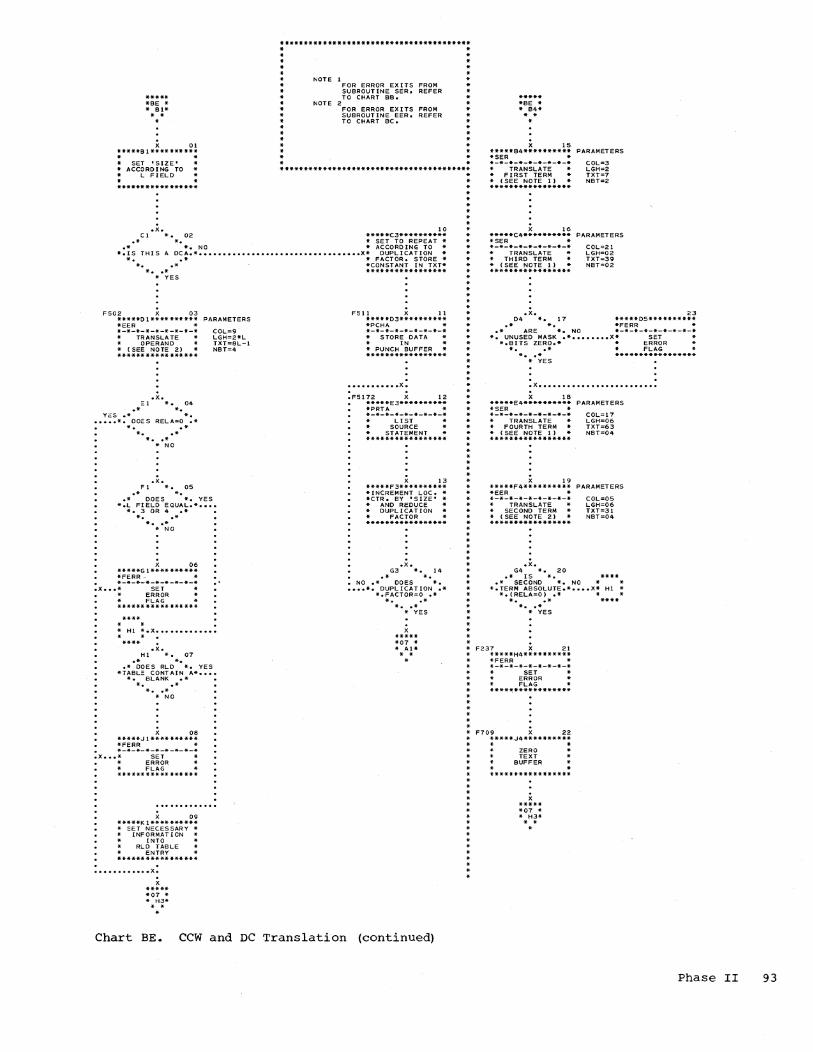
**************************************** * · . *
***** *Be * * Bl* . .
X 01
• · · · · *
NOTE I
NOTE 2
FOR ERROR EXITS FROM SUBROUTINE SER, REFER TO CHART BB.
FOR ERROR EXITS FROM SUBROUT INE EER, REFER TO CHART BC.
* · · *
* * * ·
***** ·Be * .. 84* * •
X 15 *****Bl********** . . • * *****84**********
·SER * PARAMETERS
COL=3 LGH=2 TXT=7 NBT=2
• * * SeT 'SIZE' * * *-*-*-*-*-*-*-*-* * ACCORDING TO * * ~ FIELD *
**************************************** TRANSLATE * • FIRST TERM * * (SEe NOTE 1) * *****************
.x. 10 CI *. 02 *****C3**********
.* *. * SET TO REPEAT * .* *. NO * ACCORDING TO *
*.15 THIS A DCA.* •••••••••••••••••••••••••••••••••• X* DUPLICATION * *. • * * FACTOR. STORE *
*. .* *CONSTANT IN TXT* *. .* *****************
* YES
F502 X 03 *****01********** *EER * *-*-*-*-*-*-*-*-*
TRANSLATE * * OPERAND * (SEE NOTE 2) * *****************
.x. EI *. 04
.* *. YES .* *.
••••• -. DOES RE~A=O .* -. .* *. .* * •• * * NO
.x. FI *. 05
.* *.
PARAMETERS
COL=9 ~GH=2*~ TXT=8L-l NST=4
.* DOES *. YES *.L Fle~D EQUAL.* ••••
*. 3 OR 4 .* *. .* * •• * * NO
X 06 *****GI********** *FERR * *-*-*-*-*-*-*-*-* .x ••• * SET * ERROR * * F~AG * ****** ***** *** ***
."
* HI *.X ••••••••••••• * •
.x. HI *. 07
.* *. .* DOES RLD *. YES *TABLE CONTAIN A* ••••
*. BLANK .* *. .* * •• * * NO
x OS *****JI********** *FERR * *-*-*-*-*-*-*-*-*
.x ••• * SET * * ERROR * * F~AG * *********** ******
X 09 *****KI********** * SET NECESSARY *
INFORMAT ION INTO
RLD TABLE * * ENTRY * *****************
: ........... x: x
***** *07 * * H3* * •
FSll X II *****03********** *PCHA * *-*-*-*-*-*-*-*-* * STORE DATA * * IN * * PUNCH BUFFER * *****************
••••••••••• X. . . .F5172 X 12
*****E3********** *PRTA * *-*-*-*-*-*-*-*-* * LIST *
SOURCE * STATEMENT * *****************
X 13 *****F3********** *INCREMENT LOC. * *CTR. BY 'SIZE' * * AND REDUCE *
DUPLICATION * * FACTOR * *****************
• x. G3 *. 14
• * *. • NO.* DOES *. •••• *. DUPLICATION .*
*.·FACTOR=O .* *. .*
* •• * * YES
x ***** *07 * * AI* . .
Chart BE. CCW and DC Translation (continued)
* · * * · *
* ·
X 16 *****C4********** ·SER * *-*-*-*-*-*-*-*-*
TRANSLATE * * THIRD TERM * * (SEE NOTE 1) .. *****************
PARAMETERS
COL=21 LGH=02 TXT=39 NBT=02
· · .x. 23 04 *. 17 *****05**********
.* *. -FERR .. .* ARE *. NO *-*-*-*-*-*-*-*-*
*. UNUSED MASK .* •••••••• X* SET * * *.BITS ZERO.* * ERROR *
*..* * FLAG * *. .* *****************
* * * YES
* · . . .x •••••••••••••••••••••••••
* · · · * *
· *
* · * · * *
X 18 *****E4********** *SER * *-*-*-*-*-*-*-*-* * TRANSLATE * .. FOURTH TERM * * (SEE NOTE 1) *****************
X 19 *****F4********** *EER * *-*-*-*-*-*-*-*-*
TRANSLATE * * SECOND TERM .. (SEE NOTE 2) * .****************
.x • G4 *. 20
.* IS * •
PARAMETERS
COL=1? LGH=06 TXT=63 NBT=04
PARAMETERS
COL=05 L.GH=06 TXT=31 NBT=04
· * .* SECOND *. NO * .. -.TERM ABSOLUTE.* •••• x* HI *
* *
*.(RELA=O) .* * * *..* ****
* •• * * YES
* F237 X 21 *****H4**********
* -FERR * .. *-*-*-*-*-*-*-*-*
SET .. .. ERROR * * * FLAG *
* * ·
****~************
: F709 x 22 *****J4********** . .
* ZERO * * TEXT * .. BUFFER * • • * .. *****************
· · · * · * * ·
x ***** *07 * * H3* * •
*
Phase II 93

RR FORMAT *********
***** *SF * * 61* • *
**** * * * ** ***.* .. 'II. * * ** * ** ** ** *** . . NOTE 1 *
* NOTE 2.
FOR ERROR EXITS FROM * SUBROUTINE SER, REFER * TO CHART BB,
* FOR ERROR EX ITS FROM SUBROUTINE EER, REFER * TO CHART BC.
* .. *** * ****.* ** *** * * * * .. *** ** **** * * * *
.x. FAOS 08 Bl *. 01 *****B2**********
.* *. *SER * .* IS *. NO *-*-*-*-*-*-*-*-*
*. DATA IN R1 .* •••••••• X* TRANSLATE *. FIELD .* * I FIELD *..* * (SEE NOTE 1)
* •• * ***************** * YES
X 02 *****C1********** *SER * *-*-*-*-*-*-*-*-* .. TRANSLATE * * R2 FIELD .. (SEe NOTE 1) * *****************
.x. 01 *. 03
.* *.
PARAMETERS
COL=03 LGH=Ol TXT=15 NBT=02
PARAMETERS
COL=03 * LGH=02 * TXT=15 NST=02
* * * *
* * * *
* *
NO .* *. •••. *. IS RELA=O .* *. .* *. .*
* •• * .. YES
X 04 *****E1********** *SER * *-*-*-*-*-*-*-*-* * TRANSLATE • * Rl FIELD * * (SEE NOTE J) * *****************
PARAMETERS
COL=OS LGH=Ol TXT=ll NBT=02
. . .X •••••••••••••••••••••••••
.FA12 .X. F! *. 05 .* 'II.
.* *. YES *. IS RELA=O .* ••••
*. .* *. .* 'II •• *
* NO
. . ••••••••••• X.
FA!21 X 06 *****G1********** *FERR * *-*-*-*-*-*-*-*-* * SET *
ERROR * FLAG * ***********.***-*
* • *SF *.x. * HI'll **** •
F730 X 07 *****Hl********** .. STORE ZERO * *IN TEXT BUFFER. * EXCEPT • * FOR OPERATION * * CODE * ***************** . .
.X ••••••••••• x
***** *07 *. * H3* * *
Chart BF. RR and RS Format Translation
94
· * · · * · * * * *
* · · * • *
* · · * · * *
· · '*
· · * · · * · * · *
* *
* *
RS FORMAT *********
***** *SF * * 84* * *
X 09 *****84********** *SER * *-*-*-*-*-*-*-*-*
TRANSLATE * * R3 FIELD * (SEE NOTE 1) * *****************
.x. C4 *. 10
.* *. NO .* * • • , •• *. IS REL.A=O .*
*. .* *. .* * •• * * YES
X 11 *****04********** *SER * *-*-*-*-*-*-*-*-*
TRANSL.ATE * * Rl FIELD * * (SEE NOTE 1) * *****************
:FAI2 .X. E4 *. 12
. .* *. • NO .* *. .X •• *. IS RELA=O .*
*. .* *. .* * •• * * YES
X 13 *****F4********** *EER * *-*-*-*-*-*-*-*-* * TRANSLATE * * 02(B2) FIELO * * (SEE NOTE 2) * *****************
PARAMETERS
COL.=03 LGH=Ol TXT=15 N8T=02
PARAMETERS
COL.=05 LGH=Ol TXT=11 NST=02
PARAMETERS
COl..=07 LGH=03 TXT=31 NBT=02
.X ••••••••••• x
***** *07 * * H3* * *
.FA121 14 *****H4********** *FERR * *-*-*-*-*-*-*-*-* • •• x. SET * ERROR *
FLAG * *****************
F730 X 15 *****J4********** * STORE ZERO * *IN TEXT BUFFER * • * EXCEPT * •••• * FOR OPERATION * * CODE * *****************

S[ FORMAT *********
***** *8G * * 82* * *
* * * * * · * * · * · *
FAOS .X.
PARAMETERS
CCL=03 LGH=02 TXT=15 NBT=04
82 *. 01 .* *.
.* LPSW, *. YES -. SSM .H[ O.S [0. .- ••••
*. T[O.TCH .* *. .*
* •• * * NO
X 02 *****C2********** *SER * *-*-*-*-*-*-*-*-*
TRANSLATE * * [F[ELD * (SEE NOTE 1) * *******.*********
* *
* * * · · · * * · · * ·
FA12 .X. 02 *. 03
.* *. Ne .* *. •••• *. [S RELA=O .*
*. .* *. .* * •• * * YES
. . .X •••••••••••
:FA22 X all. *****E2********** *EER * *-.-*-*-*-*-*-*-* * TRANSLATE • 01 (81) FIELD * (SEE NOTE 2) * *****************
PARAMETERS
COL=07 LGH=03 TXT=31 NBT=02
.X ••••••••••• x
***** *07 * * H3* * •
:FA121 05 **'*'**G2********'** *FERR • *-*-*-*-*-*-*-*-*
••• x* SET * * ERROR
FLAG * *****************
F730 X 06 *****H2E********* * STORE ZERO * *IN TEXT BUFFER * • * EXCEPT * •••• * FOR OPERATION .. • CODE * .****************
· * * * *
* * · *
* * · * * *
* *
* * * * * * * * *
* *
* * * * * * * * * * * * * * *
* *
· * * * * *-******-***--******.**********
* * * NOTE 1 -FOR ERROR EXITS FROM -
.. SUBROUTINE SER, REFER * * TO CHART BB. * * NOTE 2 -
FOR ERROR EXITS FROM -SUBROUTINe eeR, REFER -* TO CHART ee.
* * *************-***************.*
RX FORMAT *********
***** *BG * * B4* * •
X 07 *****84********** *SER * *-*-*-*-'*-*-*-*-*
TRANSLATE * * X2 F[ELD * (SEE NOTE I) * *****************
.x. C" *. 08
.* *. NO .* *.
•••. *. [S RELA=O .* *. .* *. .* * •• * * YES
X 09 *****04********** *SER * *-*-*-*-*-*-*-*-*
TRANSLATE * * Rl FIELD * (see NOTE 1) • *****************
.FAI2 .X. E4 •• 10
• .* *. • NO .* *. .x •• *. [5 RELA=O .*
-. .* *. .* * •• * * YES
:FA22 X 11 *****F4********** *EER * *-*-*-*-*-*-*-*-* * TRANSLATE * * 02(82) FIELD * * (SEE NOTE 2) *****************
PARAMETERS
eOL=03 LGH=OI TXT=15 NBT=02
PARAMETERS
COL=05 LGH=Ol TXT=11 NBT=02
PARAMETERS
COL=07 LGH=03 TXT=31 NBT=02
.X ••••••••••• x
***** *07 * * H3* * *
:FA121 12 *****H4********** *FERR * *-*-*-*-*-*-*-*-*
• •• x* SET * * ERROR * FLAG * *****************
F730 X 13 *****J4********** * STORE ZERO • -[N TEXT BUFFER * • * EXCEPT * •••• • FOR OPERAT[ON * * CODE • *****************
Chart BG. RX and SI Format Translation
Phase II 95

***** *BH * * 83* * *
.*. FEOI .x. FB03 .*. 82 *. 02 83 *. 01 64 *. 16 .* *. .* *. .* *.
YES.* IS *. YES.* PACK, *. NO .* IS *. NC •••••••••••••••••• *. DATA IN Ll .*X •••••••• *. UNPK,MVO, .* •••••••• X*. DATA IN L .* ••••••••••••••••••
*. FIELD .* *. DECIMAL .* *. FIELD .* *..* *..* *. .*
* •• * * •• * * •• * * NO * * YES
X 03 *****c 1 ********** *SER * *-*-*-*-*-*-*-*-* * TRANSLATE * * Ll FIELD * *(SEE NOTE l,lA)* ****** ***** ******
.X. [)1 *. 04
• * *. NO .* *.
.X. C2 *. 10
.* *. • * *. YES
*15 01 A SYMBOL * •••• *. .* *. .* * •• * * NO
X 11 *****02********** · . * ZERO TEXT AND *
••• *. IS RELA=O .* •••••• *PLACE ABSOLUTE * *'11 ALUE IN eUFFER* *. . * *. .*
* •• * * YES
· . ***************** · . * 03 * * •
X 05 *****E 1 **** ****** * •
STORE Ll * * FIELD IN * TEXT BUFFER . *********** ******
12 *****E2** ******** * PLACE LENGTH * * ATTRIBUTE • * FROM SYMBOL *X ••• *T ABLE IN BUFFER*
• * ********* ********
• X • .. x ............................... .
FBl7 .X. FB23 .*. Fl *. 06 F2 *. 13
.* *. .* *. .* IS *. NO .* *. YES *. DATA IN L2 .* •••••••• X*IS 02 A SYMBOL * •••• *. FIELD .* *. .* *..* *..*
* •• * *. • * * YES * NO
X 07 *****Gl********** *SER * *-*-*-*-*-* -*-*-*
TRANSLATE * L2 FIELD * *(SEE NOTE 1.18)* *****************
X 14 *****G2********** · . * ZERO TEXT AND *
•••••• *FLACE ABSOLUTE * *VALUE IN BUFFER* · ************* ****
FB20 .X. . 15 HI *. 08
.* *. NO .* *.
• •• *. IS RELA=O .*
X **** · . * 03 *
• *
*. • * *. .*
* •• * * YES
X 09 *****JI********** . . * STORE L2 * FI ELO IN
TEXT BUFFER
*****H2********** * PLACE LENGTH * * ATTRIBUTE • * FROM SYMBOL *X ••• *TABLE IN EUFFER* · . *****************
• X • • X ......................... . X
**** . . * F5 * .
Chart RH.
96
SS Format Translation
. . * 03 * . .
X 17 *****C4********** *SER * *-*-*-*-*-*-*-*-* * TRANSLATE * L FIELD * *(SEE NOTE 1dC)* *****************
FAI21 X 24 .X. *****03********** 04 *. 18 *FERR * .* *. *-*-*-*-*-*-*-*-* NO .. * *. * SET *X •••••••• *. IS RELA=O .*
ERROR * *. .* * FLAG * *..* ***************** * •• *
F730 X 25 *****E3********** * STORE ZERO * *IN TEXT BUFFER * * EXCEPT * * FOR OPERAT ION * * CODE * *****************
x ***** *07 * * H3* ..
* YES
FB07 .X. C5 *. 19
.* * • .* *. YES *IS 01 A SYMBOL * ••••
*. .* *. .* * •• * • NO
FBl4 X 20 *****05********** * • * ZERO TEXT AND *
•••• *PLACE ABSOLUTE * *VALUE IN BUFFER*
• * *****************
21 *****E5********** * PLACE LENGTH * * ATTRIBUTE • * FROM SYMBOL *X ••• *TABLE IN BUFFER* · . *****************
· '. * F5 *.X. · . • **** .. .F826 X 22
*****F5********** *EER *
• *-*-*-*-*-*-*-*-* ••••••••••••••••• x* TRANSLATE
* NOTE 1 FOR ERROR EXITS FROM SUBROUTINE SER. REFER TO CHART BB.
* NOTE IA PARAMETERS FOR Ll FIELD
COL=OS TXT=11 LGH=ll N8T=02
* NOTE 18 PARAMETERS FOR L2 FIELD
COL=03 TXT=15 LGH=O 1 N8 T=02
* NOTE Ie PARAMETERS FOR L FIELD
COL=03 TXT=15 LGH=02 NBT=02
* NOTE 2
* 02(B2) FIELD * *<SEE NOTE 2 t 2A)* *****************
FA22 23 *****G5********** *EER * *-*-*-*-*-*-*-*-* * TRANSLATE * * 01(81) FIELD * *(SEE NOTE 2,2B)* *****************
***** *07 * * H3* ..
FOR ERROR EX ITS FROM SUBROUTINE EER. R~FER TO CHART BC.
* NOTE 2A PARAMETERS FOR 02(B2) FIELD
* NOTE 2B
COL=15 TXT=14 LGH=03 NBT=02
PARAMETERS FOR 01 (BI) FIELD
COL=07 TXT=3I LGH=03 NBT=02
. *******************************************************************

This appendix contains three crossreference tables which may be used with the Autochart diagrams within this manual. Use of the tables will enable a user to locate any label appearing on any chart, all references to a particular entry connector, and all blocks where a subroutine is used.
BLOCK LABEL
ccw
CNOP
CVTL
C311
C804
C805
C811
C819
C8201
C824
C825
C901
C903
C908
C910
C9101
C915
C9192
C923
C926
C9271
C930
DC
BLOCK Loe
AAB2
ACBI
BBHI BBH5
04B5
07AI
07EI
07GI
07A2
07C4
07H3
07G2
BOBI
BOCI
BoB2
BoFI
BoGI
BoB4
BoE4
BABI
BAC2
BAOI
0705
ABB2
BLOCK NUMBER
AAOI
ACOI
BBIO BBI8
0420
0701
0705
0707
0710
0718
0727
0716
BOOI
B003
Bo02
Bo06
B007
B009
Bol2
BAOI
BA08
BA03
0723
ABOI
APPENDIX A: AUTOCHART CROSS-REFERENCE TABLES .
TABLE I: LABELS
This table lists all labels that appear on charts. To the right of each label is the grid location and the block number associated with the block that bears that label.
BLOCK LABEL
DROP
OS
0001
0002
00053
0006
00081
00082
00084
00101
0020
00223
0024
0104
0107
0140
EF07
EF08
EGll
EG12
EGIS
EG16
BLOCK LOC
AOG4
ACA4
BBB2
BBBI
BBOI
BCBI
BCE1
BCFl
BCE2
BCF2
BBE4
BBG3
BBKS
BAB4
BAB5
BBGI
AHHS
AHH4
AJJ4 AKE2
AK02 AL01
A.,K3 AKG2
AK04
BLOCK NUMBER
Ao12
ACIO
BB04
BBOI
BB03
BC01
BC04
BC05
BC08
BC09
BB14
BB24
8B20
BA09
BA14
BB09
AH16
AH15
AJI0 AK05
AK04 AL04
A.,12 AK07
AK08
Appendix A: Autochart Cross-Reference Tables 97

BLOCK BLOCK BLOCK BLOCK BLOCK BLOCK BLOCK BLOCK BLOCK LABEL LaC NUMBER LABEL LOC NUMBER LABEL LOC NUMBER
EJECT ADBI ADOI FAl21 BFGI BF06 F730 BFHI BF07 BFH4 BFl4 BFJ4 BFl5 BGG2 BG05 BGH2 BG06
EM04 AMC2 AM04 BGH4 BGl2 BGJ4 BGl3 BHD3 BH24 BHE3 BH25
EM08+4 AMD2 AM05 FA22 BGE2 BG04 F744 BBB5 BB26
BGF4 BGll END ADB4 AD08 BHG5 BH23
F746 BCB5 BCl4
ENTRY ADFI AD03 FBOI BHB3 BHOI MACHA AJB2 AJOI
EN07 AMF3 AMl5 FB03 BHB4 BHl6 MACHB AHB4 AH09
ENII AMJ3 AMl8 FB07 BHC5 BH19 MACHC AIA2 AIOI
ENl2 AMH3 AMl7 FBl4 BHD5 BH20 MACHO AIB2 AI02
EN13 AMH4 AMl2 FBl7 BHFI BH06 MACHE AKB3 AKOI
EN25 ANBI ANOI FB20 BHHI BH08 MACHF AKB2 AK02
EN26 AMJ2 AM21 FB23 BHF2 BH13 MACHG ALAI ALOI
EN27 AMH2 AM20 FB26 BHF5 BH22 MACHH ALBI AL02
EPOI ANH3 ANI I FCOI BCJ3 BCl3 MACHI AHF4 AH13
EP02l ANF3 AN09 FHll 07Bl 0702 MACHJ AHB3 AH08
EQU AECI AEOI FH12 0701 0704 NOTE AOD4 A029
ER03 ANC4 ANl7 F232 BCB4 BC13 ORG AGCI AGOI
ER04 ANE5 AN25 F237 BEH4 BE2l SEE NOT::: I BAD4 BAll
EVEI AME4 AM09 F502 BEDI BE03 SEE NOE 2 BAE4 BA12
EXTRN AEC4 AE09 F5l1 BED3 BEll SPACE AGC4 AG08
FA05 BF:B2 BF08 F5172 BEE3 BEl2 BGB2 BGOI START AFB4 AF08
FA12 BFE4 BFl2 F708 BBB4 BB25 BFFI BF05
USING AHBI AHOI BGD2 BG03 F709 BEJ4 BE22 BGE4 BGlO lCTL AFBI AFOI
98
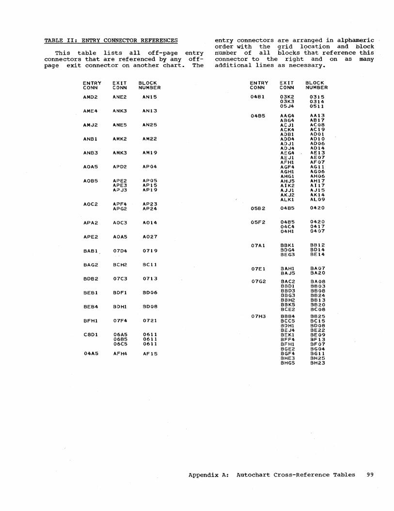
TABLE II: ENTRY CONNECTOR REFERENCES entry connectors are arranged in alphameric order with the grid 19cation and block
This table lists all off-page entry number of all blocks that reference this connectors that are referenced by any off- connector to the right and on as many page exit connector on another chart. The additional lines as necessary.
ENTRY EXIT BLOCK ENTRY EXIT BLOCK CONN CONN NUMBER CONN CONN NUMBER
AMD2 ANE2 AN15 04B1 03K2 0315 03K3 0314 05..14 0511
AME4 ANK3 AN13 04B5 AAG4 AA13
ABG4 AB17 AM..I2 ANE5 AN25 AC..Il ACoe
ACK4 AC19 ADB1 ADOI
ANBI AMK2 AM22 ADD4 AD10 AD..I1 AD06 AD..I4 A014
ANB3 AMK3 AM19 AEG4 AE13 AE..Il AE07 AFHl AF07
AOA5 AP02 AP04 AGF4 AG11 AGHI AG06 AHG1 AH06
AOB5 APE2 APOS AH..IS AH17 APE3 AP1S AIK2 1'.117 AP..l3 AP19 A..I..Il A..I1S
AK..I2 AK14 ALKI AL09
AOC2 APF4 AP23 APG2 AP24 05B2 04BS 0420
APA2 AOC3 A014 05F2 04BS 0420 04C4 0417 04HI 0407
APE2 AOAS A027
07AI BBKI BB12 BAB1 0704 0719 BOG4 B014
BEG3 BE14
BAG2 BCH2 BC1l 07El BAHI BA07
BA..I5 BA20 BDB2 07C3 0713 07G2 BAC2 BAoe
BBOI BB03 BEBI BOFI B006 BBD3 BB08
BBG3 BB24 BBH2 BB13
BEB4 BOHI B008 BBK5 BB20 BCE2 BC08
07H3 BBB4 B625 BFHl 07F4 0721 BCC5 BC1S
BOHI Booe BE..I4 BE22
C8Dl 06A5 0611 BEKI BE09 06B5 0611 BFF4 8F13 06C5 0611 BFHl BF07
BGE2 BG04 04AS AFH4 AF15 BGF4 BG11
BHE3 BH25 BHG5 BH23
Appendix A: Autochart Cross-Reference Tables 99

TABLE III SUBROUTINE USAGE
This table lists the subroutine names as they appear in subroutine blocks on the individual charts. The first appearance of a subroutine block has the name of that
SUIjROUTINE NAME
BA
BAR
BUMP
CVTL
DCC
DCF
OCF2
OCXl
OOUT
DROP
EER
ERR
EVE
100
ENTRY CONN
AMB3
BLOCK LOC
BABI BDBI BDB4
AAB2 AFG4
05J4
BBF4 BBHl BBH5
ANK5
ABC2 ABJ2 ACB4 ACG4
ANF4
ANH5
07Jl
BBJI
BBE4 BCBl BEDI BEF4 BFF4 BGE2 BGF4 BHF5 BHG5
AAF3 ABF3 ACJ2 ACJ5 ADDI AOD5 ADJ2 ADJ5 AEG5 AEJ2 AFE5 AFHl AGF5 AGH2 AHG2 AHJ5 AIK2 AJJI AKJ2 ALJ2 ANEI 04C4
AAB4
BLOCK NUMBER
BAOI BOOI B009
0511
BB15 BBIO BB18
AN29
AB02 ABIO ACll AC16
AN19
AN20
AN27
0709
BBll
BB14 BCOI BE03 BE19 BF13 BG04 BGll BH22 BH23
AA15 ABIB AC09 AC20 A002 AD 11 A007 A015 AE14 AE08 AF16 AF07 AG12 AG07 AH07 AH17 AI17 AJ15 AK14 AL29 AN04 0417
AA08
block as it appears in the first line of' the block. To the right of the name is found the entry point into the subroutine, if it is present, and the grid location and block number of each block where this subroutine reference appears.
SUBROUTINE NAME
EVE
FERR
INOUT
ENTRY CONN
AMB3
BLOCK LOC'
AAC2 AAE4 AAF2 ABC4 ACBl ACFl AOBI AOB4 AOFI AOG4 AEC4 AEDI AFCI AFC4 AGCl AGD4 AGE4 AHBI AHB4 AHEI AHF4 AIB2 AIC4 AIF2 AIF4 AJB2 AJE2 AJG3 AJJ4 AKB2 AKE2 AKF4 ALBI ALC5 AL02 ALD3 ALFI ALF3 ALG5 04B3 04C3 04F4 04G2
BBD3 BBG3 BBH2 BBK3 BCB5 BCHI BED5 BEGI BEH4 BEJI BFGl BFH4 BGG2 BGH4 BHD3 07F2
BAE4 03B3 03J3 03K2 04Bl 05G4 05G5 05J2 06C3 0602 0603 06Hl 07Fl
BLOCK NUMBER
AA02 AAll AA05 AB13 ACOI AC05 AOOI AD08 A003 A012 AE09 .AE02 AF02 AF09 AGOI AG09 AGIO AHOI AH09 AH04 AH13 AI02 AI09 AI06 AI12 AJOI AJOIt AJ07 AJlO AK02 AK05 AKI0 AL02 AL22 AL12 ALl 6 AL06 AL18 AL25 0411 0412 0419 0408
BB08 BB24 BB13 BB23 BC14 BC07 BE23 BE06 BE21 BE08 BF06 BF14 BG05 BG12 BH24 0715
BA12 0301 0313 0315 0401 0514 0517
0621 0606 0622 0614 0706

SUBROUTINE ENTRY BLOCK BLOCK SUBROUTINE ENTRY BLOCK BLOCK NAME CONN LOC NUMBER NAME CONN LOC NUMBER
PCHA BAFI BA05 STORE AAC4 AA09 BOEI B005 AA02 AA03 BE03 BEll AAF4 AA12 07E5 0724 AAG2 AA06 07H3 0727 ACCI AC02
ACGl AC06 AOC4 AOO9
PRTA BAEI BA04 AOGI AOO4 BAG5 BAl9 AOH4 AD13 BBKI BB12 AE04 AEIO BCF2 Be09 AEEI ~E03
BOF4 B013 AFOI AF03 BEE3 BEI2 AF04 AFI0 07G2 0716 AGOI AG02
STORE AGF4 AGll AHCl AH02
PRTERR BAC4 BAlO AHC4 AHIO AHFI AH05 AHG4 AH14
SER BBBI BBOI AIC2 AI03 BBB2 BB04 AI04 AIlO BBGI BB09 AIG2 AI07 BBG5 BB17 AIG4 AIl3 BEB4 BE15 AJC2 AJ02 BEC4 BEI6 AJF2 AJ05 BEE4 BE18 AJH3 AJ08 BFB2 BF08 AJK4 AJll BFB4 BF09 AKC2 AK03 BFCl BF02 AKF2 AK06 BF04 BFll AKG4 AKll BFEI BF04 ALC! AL03 BGB4 BG07 AL05 AL23 BGC2 BG02 ALE2 ALl3 BGD4 BG09 ALE3 AL17 BHC! BH03 ALGI AL07 BHC4 BH17 ALG3 ALl9 BHGI BH07 ALH5 AL26
ANF3 AN09
SKNB BCG2 BCIO BDE4 B012
STOCAW AP82 AP02 TLUL AFH4 AF15 APB3 AP12 ANBI ANOI APF4 AP23 APG3 APt7 TLUN 05C3 0507
Appendix A: Autochart Cross-Reference Tables 101

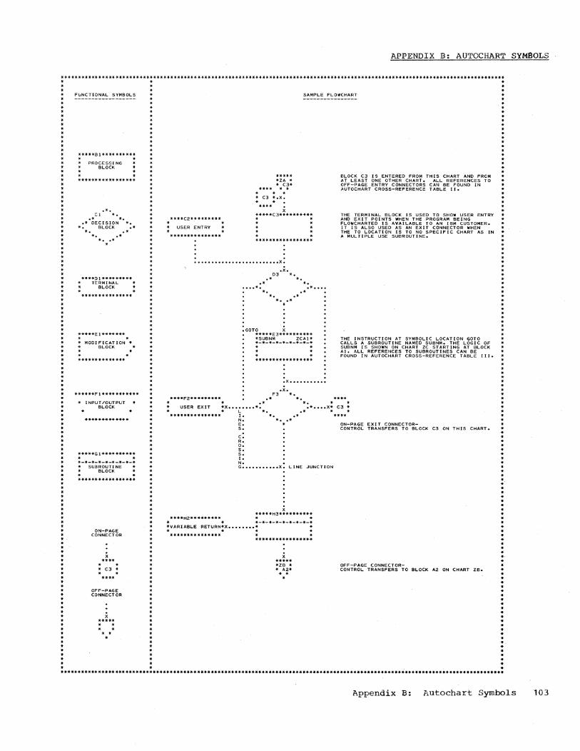
APPENDIX B: AUTOCHART SYMBOLS
*******. __ ._. ____ ••• _____ * ____ • _______ * ____ ••• ___ • _______ • ___ • __ *** ___ * ___ • __ ••• ____ * __ **_**_*._ •• __ *_* ___ ****_A._AAA*AA_A _______ • · . . · · · · * · * · * · · · * · · · · · ·
FIJNCTIONAL SYMBOLS ------------------
*****81********** * * PROCESSI NG
* BLOCK . _*_*A*A**AA**_* __
.'. C1 *.
.- *. ._ DECISION A.
*. BLOCK .-*. . * *. .* * •• *
*
· · · · * · * * · · · · ·
SAMPLE FLOWCHART
****C2********* • . * USER ENTRY
.**************
• .e*** *ZA * * C3· . . · .. * C3 *.x.
* * X
*****C3********** * • * • * * · .
. .
............................... X •
. x. 03 * ..
.* * • • * * • ..... *. ..* •••• *. .* *.. ..* * ... * .
:GOTO X *****E3********** *SUBNM ZCAl* *-*-*-*-*-*-*-*-* · . .
. . .X ............ .
• x. F3 *.
****F2********* .* *.
.' · · .. · * · · · · · 8LOCK C3 IS ENTERED FROM THIS CHART AND FROM *
AT LEAST ONE OTHER CHART. ALL REFERENCES TO OFF-PAGE ENTRY CONNECTORS CAN BE FOUND IN AUTOCHART CROSS-REFERENCE TABLE II •
.. · THE TERMINAL BLOCK IS USED TO SHOW USER ENTRY AND EXIT POINTS WHEN THE PROGRAM BEING FLOWCHARTED IS AVAILABLE TO AN IBM CUSTOMER. * IT IS ALSO USED AS AN EXIT CONNECTOR WHEN * THE TO LOCATION IS TO NO SPECIFIC CHART AS IN A MULTIPLE USE SUBROUTINE.
* · .. .. .. · .. · · THE INSTRUCTION AT SYMBOLIC LOCATION GOTO *
CALLS A SUBROUTINE NAMED SUBNM. THE LOGIC OF * SUBNM IS SHOWN ON CHART ZC STARTING AT BLOCK * Al. ALL REFERENCES TO SUBROUTINES CAN BE FOUND IN AUTOCHART CROSS-REFERENCE TABLE 111. .. · .. · · · * * .* *. * *
* USER EXIT *X •••••••• *. .* •••• X* C3 * * L *. .* * *
*************** 1. *. .* N. * •• * E. * ON-PAGE EXI T CONNECTOR-s. CONTROL TRANSFERS TO BLOCK C3 ON THIS CHART.
C: R. O. s. s. I. N. • G ••••••••••• x. LINE JUNCTION
X *·***H3**********
****H2********* * * * * *-*-*-*-*-*-*-*-* *VARIABLE RETURN*X •••••••• * * * * *
*************** * * ***.*.***********
x ***** *ZB * * A2* • *
OFF-PAGE CONNECTOR-CONTROL TRANSFERS TO BLOCK A2 ON CHART ZB •
* · .. .. .. · * · · .. .. ..
· .. .. · .. ..
.. ·
.. ..
.. ' . ..
.. **********************************************************************************************************************************
Appendix B: Autochart Symbols

GLOSSARY
address: The unique identification register, storage location, or other source or destination.
of a data
Assembler instruction statement: An assembler language statement that directs the operation of the assembler or affects the format, content, location assignments, or register usage of its output, and usually does not cause any machine language instructions to be produced.
compound expression: A combination of two or, at most, three simple expressions, connected to each other by arithmetic operators.
ESD cards: These cards or card images on tape are part of the object program deck, and are produced for each START, ENTRY, and EXTRN Assembler instruction to provide complete linkage between different object programs.
Intermediate Text: The partially translated source statement produced by Phase I and used as input to Phase II.
location counter: The internal counter used to assign consecutive storage addresses to program statements.
machine instruction: An Assembler language statement specifying an operation that corresponds to a machine operation or operations, and that causes the Assembler to produce a corresponding machine-language instruction or instructions.
Operation Code Table: The table that is part of Phase I and contains each symbolic operation code, its machine equivalent, and the location of the routine necessary to translate the operand field.
Register Phase II
10Ll
Table: that
The table constructed by contains general register
numbers, their corresponding values and relocatable attributes and is used to assign base registers and displacements when the assembler must compute addresses.
relocation: Modification of address constants to compensate for the difference between the or1g1n assumed in an object program and its assumed origin relative to other object programs with which it is combined.
RLD cards: These cards or card images on tape are part of the object program, and are produced for each relocatable address constant and CCW defined in the program to allow the Relocatable Loader to reevaluate symbols and expressions within address constants and CCW's.
RLD Table: The table constructed by Phase II that contains the data necessary to produce the RLD cards.
simple expression: A single symbol or a single self-defining value used as an operand.
symbol: Any collection of which something is known referred to; a name.
characters by and can be
Symbol Table: The table constructed by Phase I that contains all the symbols, and their attributes, contained in the source program.
Symbol Table Deck: The deck (produced in a card system only) that contains the attributes of all the symbols in the object program and is used as input to Phase II.
TXT -cards: These cards or card images on tape, are part of the object program deck, and contain the machine language statements constructed from the symbolic statements in the source program.

Assembler instructions (see also specific instructions)
Phase I Errors 21,28-41,53-60 Translation 26,28-41,53-60
Phase II Errors 78-83,87-91 Translation 74,75,78-83,87-91
Assembler Program Purpose 7 Organization 7
Attributes, Symbol 17 Autochart Cross Reference Tables 95-100
BAR Subroutine 20,99 Buffer areas, output 11 BUMP Subroutine 21,99
Cards (see also specific cards) ESD - 66,71,81,82 RLD 66,71,73,82 TXT 66,71 Symbol Table 18
Card buffer areas 11 CCW Assembler instruction
Phase I Errors 21,52 Intermediate text 16,28,29 Source statement 28 Translation 28,53
Phase II Errors 74,75,90,91 Special considerations 73,79
CNOP Assembler instruction Phase I
Errors 21,55 Intermediate text 16,31 Translation 30,55
Phase II Errors 75,86,87 Special considerations 76 Translation 81,86,87
DC Assembler instruction Phase I
Errors 21,54 Intermediate text 16,30 Translation 29,54
Phase II Errors 74,75,90,91 Special considerations 76 Translation 83,90,91
nec Subroutine 19 DCF Subroutine 19 DCX Subroutine 19 DOUT Subroutine 77,78,98 DROP Assembler instruction
Phase I Errors 21,56 Intermediate text 16,33 Translation 33,56
Phase II
Errors 74,75,88 Special considerations 73 Translation 82,88
DS Assembler instruction Phase I
Errors 21,55 Intermediate text 16,32 Translation 32,55
Phase II Errors 75,90 Translation 82,90
EER Subroutine 75,98 EJECT Assembler instruction
Phase I Errors 21,56 Intermediate text 16,33 Translation 33,56
Phase II Errors 75,85 Translation 81,85
END Assembler instruction Phase I
Errors 21,56 Intermediate text 16,34 Special considerations 26 Translation 34,56
Phase II Errors 75,89 Translation 82,89
ENTRY Assembler instruction Phase I
Errors 21,56 Intermediate text 16,35 Translation 35,56
Phase II Errors 74,77,88 Special considerations 67 Translation 78,81,88
ERR Subroutine 20,24,98 Errors (see specific instructions) Error flags, list of 20,77 EQU Assembler instruction
Phase I Errors 21,56,57 Intermediate text 16,36 Translation 35,56
Phase II Errors 82 1 89 Translation 82,89
ESD Card Described 67 Format 71
EVE Subroutine 19,20,24,98 EXTRN Assembler instruction
Phase I Errors 21,57 Intermediate text 16,37 Translation 36,57
Phase II Errors 74,88
Index 105

Special considerations 67 Translation 79,81,88
FERR Subroutine 77,79,98
ICTL Assembler instruction Phase I
Errors 21,58 Intermediate text 16,37 Translation 37,58
Phase II Translation 81,87
ID-Code (see also Intermediate text and specific instruction)
Phase I 15,16,20,23,24 Phase II 67,78,79
INOUT Subroutine 23,76,77,99 Instructions (see specific instructions and formats)
Intermediate text Detailed (see specific instructions) General 15,16 Summary 16
Listing, Program 7,8,9,72 Location counter 7,14,17,20,21,22,26 Logic flow
Phase I 7,23,49,51 Phase II 8,78,85,86
Machine instructions. (see specific instruction format)
Object program 7-11,14,67,73,76,78 Operand translation (see specific instruction)
Operation code (see also Operation Code Table)
Errors 8 Translation 7,8
Operation Code Table Description 15 Used 7,8,14,23
ORG Assembler instruction Phase I
Errors 21,59 Intermediate text 16,38 Translation 38,59
Phase II Errors 82,89 Translation 82,89
Output Phase I 4-11,16,17 Phase II 4,11,67-72
Output buffer area 11 Output cards (see specific card) Output listing 7,8,9,72
PCHA Subroutine 76,99 Phase I
Description 7,14-22 Logic flow 7,12,24-27
Phase II Description 8,67-77 Logic flow 8,13,78-80
Program listing 7,8,9,72 PRTA Subroutine 76,79,99 PRTERR Subroutine 99
106
Register Table Described 73 Used 75,78,82
Relocation List Dictionary Table (see RLD Table)
RLD Card Described 67 Format 71
RLD Table Described 73 Used 67,77,78
RR Format Phase I
Errors 21,61 Intermediate text 16,42 Translation 42,61
Phase II Errors 74,75,92 Translation 75,79,80,83,92
RS Format Phas.e I
Errors 21,61 Intermediate text 16,43 Translation 42,56
Phase II Errors 74,75,92 Translation 75,79,80,84,92
RX Format Phase I·
Errors 21,62 Intermediate text 16,44,45 Translation 45,62
Phase II Errors 74,75,93 Translation 75,79,80,84,93
SER Subroutine 74,75,99 SI Format
Phase I Errors 21,63 Intermediate text 16,45,46 Translation 45,63
Phase II Errors 74,75,93 Translation 75,79,80,84,93
SKNB Subroutine 99 Source program 7,9,10,14,24,72 SPACE Assembler instruction
Phase I Errors 21,59 Intermediate text 16,39 Translation 38,59
Phase II Errors 81,87 Translation 81,87
SS format Phase I
Errors 21,64 Intermediate text 16,46,47 Translation 46,64
Phase II Errors 74,75,84,94 Translation 75,79
START Assembler instruction Phase I
Errors 81,88 Intermediate text 16,39 Translation 39,58

Phase II Errors 81,88 Special considerations 67 Translation 80,82,88
Storage allocation 9 STORE Subroutine 19,20,99 Subroutines, described (see also specific subroutine)
Phase I 19-23 Phase II 74,79
Symbols 7,8,14,17,19,21.22,24,26,67,74 Symbol Table
Attributes 17 Described 17 Phase I, used Phase II, used
Symbol Table card
7,8,14,22,26,27 7,8,67,74,79,80 18
Symbol Table deck 7,8,9,14,24,27,79
Tape buffer areas 11 Tables (see specific table) TLUN Subroutine 22,26,99 TLUS Subroutine 22,23,99 TXT card
Described 67,78 Format 71
USING Assembler instruction . Phase I
Errors 21,60 Intermediate text 16,40,41 Translation 40,60
Phase II Errors 74,75,82,88 Special considerations 73 Translation 82,88
Index 107


READER'S COMMENTS
IBM System/360 Basic Programming Support i tle: Basic Assembler
Program Logic Manual
; the material: Easy to Read? Well organized? Complete? Well illustrated? Accurate? Suitable for its intended audience?
)w did you use this publication? ___ As an introduction to the subject
Yes
Other ________________________________ __
Lease check the items that describe your position:
No
Form: C28-6555-1
For additional knowledge fold
___ Customer personnel _Operator ___ IBM personnel _ Programmer
_ Sales Representative _ Systems Engineer
___ Manager _Customer Engineer ___ Trainee ___ Systems Analyst _ Instructor Other ______________ _
Lease check specific criticism(s), give page number(s),and explain below: ___ Clarification on page (s) _ Addition on page (s) _ Deletion on page (s) _ Error on page (s)
~planation :
Name ________________________________ __
Address ____________________________ __
FOLD ON TWO LINES,STAPLE AND MAIL No Postage Necessary if Mailed in U.S.A.
fold

staple
fold
fold
staple
r--------------------------------------------------l I BUSINESS REPLY MAIL I I NO POSrAGE STAMP NECESSARY IF MAILED IN U. S. A. I L __________________________________________________ J
POSTAGE WILL BE PAID BY
IBM CORPORATION P. O. BOX 390 POUGHKEEPSIE. N. Y. 12602
ATTN: PROGRAM LOGIC DOCUMENTATION DEPARTMENT D89
stapll
r---------------------l I FIRST CLASS I I PERMIT NO. 81 I I i I I I POUGHKEEPSIE. N. Y. I L _____________________ J
IIIIII
111111
111111 111111 111111
111111
111111
111111
IIIIII
111111
111111
111111
fol
fol~
stapl4


C28-6555-1
llrn~ ®
International Business Machines Corporation Data Processing Division 112 East Post Road, White Plains, N. Y. 10601
o N 00 I
0\ U1 U1 U1 I -'


![Maa s360 10command_ebook-bangalore[1]](https://img.dokumen.tips/doc/110x75/5584b483d8b42a9c768b4938/maa-s360-10commandebook-bangalore1.jpg)