Embed Size (px)
Citation preview

2002 Toyota Truck Tacoma Extra Cab 2WD V63.4L (5VZFE)Vehicle » Engine, Cooling and Exhaust » Engine » Cylinder Head Assembly » Service and Repair » Removal


REMOVAL
1. REMOVE ENGINE UNDER COVER2. DRAIN ENGINE COOLANT3. 2WD, 4WD: REMOVE NO.1 EXHAUST PIPE (WITH TWC)4. DISCONNECT HEATER HOSE5. REMOVE AIR CLEANER ASSEMBLY

6. REMOVE HIGHTENSION CORDS WITH IGNITION COILS AND SPARK PLUGS
7. DISCONNECT CABLES
a. w/ Cruise Control: Disconnect the cruise control cable.b. Disconnect the accelerator cable.c. A/T: Disconnect the throttle cable.
8. DISCONNECT HOSES
a. Disconnect the brake booster hose.
b. Disconnect the EVAP hose.c. 4WD: Disconnect the A.D.D. vacuum hose.

d. Disconnect the fuel return hose.e. Disconnect the fuel inlet hose.
9. REMOVE INTAKE CHAMBER STAY
a. Remove the 2 bolts and No.1 throttle cable clamp.

b. Remove the 2 bolts and intake chamber stay.
10. REMOVE NO.2 TIMING BELT COVER11. REMOVE AIR INTAKE CHAMBER ASSEMBLY
a. Disconnect the throttle position sensor connector.b. Disconnect the IAC valve connector.c. Disconnect the 2 PCV hoses.d. Disconnect the 2 water bypass hoses.e. Disconnect the air assist hose from throttle body.
f. Remove the 4 bolts, 2 nuts, the air intake chamber assembly and gasket.
12. REMOVE INTAKE AIR CONNECTOR ASSEMBLY

a. Remove the bolt and disconnect the engine wire.b. Disconnect the fuel return hose.c. Disconnect the vacuum sensing hose from the fuel pressure regulator.d. Remove the bolt and disconnect the ground strap from the intake air connector.e. Disconnect the DLC1 from the bracket.
f. Remove the 3 bolts, 2 nuts, the intake air connector assembly and gasket.
13. DISCONNECT ENGINE WIRE PROTECTOR

a. Disconnect the 6 injector connectors.b. Disconnect the ECT sensor connector.c. Disconnect the ECT sender gauge connector.d. Disconnect the 2 engine wire clamps.e. Remove the 3 bolts, and disconnect the engine wire protector from the cylinder head.
f. Disconnect the 2 engine wire clamps from the engine.
14. REMOVE FUEL PRESSURE REGULATOR
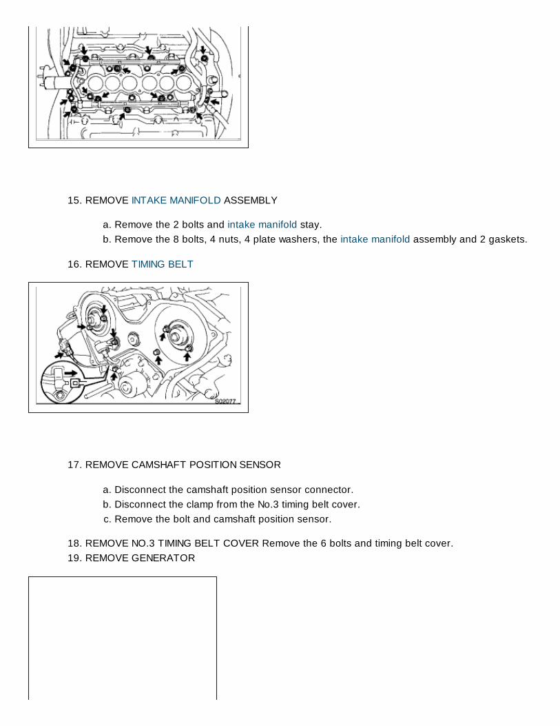
15. REMOVE INTAKE MANIFOLD ASSEMBLY
a. Remove the 2 bolts and intake manifold stay.b. Remove the 8 bolts, 4 nuts, 4 plate washers, the intake manifold assembly and 2 gaskets.
16. REMOVE TIMING BELT
17. REMOVE CAMSHAFT POSITION SENSOR
a. Disconnect the camshaft position sensor connector.b. Disconnect the clamp from the No.3 timing belt cover.c. Remove the bolt and camshaft position sensor.
18. REMOVE NO.3 TIMING BELT COVER Remove the 6 bolts and timing belt cover.19. REMOVE GENERATOR

20. REMOVE GENERATOR BRACKET
a. Remove the 2 bolts and generator bracket insulator.b. Remove the 2 bolts and generator bracket.
21. REMOVE PS PUMP BRACKET Remove the 3 bolts and PS pump bracket.
22. REMOVE EXHAUST CROSSOVER PIPE Remove the 6 nuts, crossover pipe and 2 gaskets.

23. REMOVE EXHAUST MANIFOLDS Remove the 12 nuts, 2 exhaust manifolds and 2 gaskets.
24. REMOVE CYLINDER HEAD COVERS
a. Remove the 8 bolts, seal washers, cylinder head cover and gasket.b. Remove the 2 cylinder head covers.
25. REMOVE CAMSHAFTS
NOTICE: Since the thrust clearance of the camshaft is small, the camshaft must be kept level while it is beingremoved. If the camshaft is not kept level, the portion of the cylinder head receiving the shaft thrust maycrack or be damaged, causing the camshaft to seize or break. To avoid this, these steps should be carriedout.
a. Remove the exhaust camshaft of the RH cylinder head.

1. Align the timing marks (2 dot marks) of the camshaft drive and driven gears by turning the camshaft witha wrench.
2. Secure the exhaust camshaft subgear to the main gear with a service bolt. Torque: 5.5 Nm (55 kgfcm, 49 inch lbs.)
Recommended service bolt
NOTICE: If the bolt is loose, the camshaft may tip it and cause damage in the camshaft and camshaft bearingcap.
HINT: When removing the camshaft, make sure that the torsional spring force of the subgear has beeneliminated by the operation.

3. Uniformly loosen and remove the 8 bearing cap bolts, in several passes, in the sequence shown.4. Remove the 4 bearing caps and exhaust camshaft.
b. Remove the intake camshaft of the RH cylinder head.
1. Uniformly loosen and remove the 10 bearing cap bolts, in several passes, in the sequenceshown.
2. Remove the 5 bearing caps, oil seal and intake camshaft.
c. Remove the exhaust camshaft of the LH cylinder head.

1. Align the timing marks (1 dot mark) of the camshaft drive and driven gears by turning the camshaft witha wrench.
2. Secure the exhaust camshaft subgear to the main gear with a service bolt. Torque: 5.5 Nm (55 kgfcm, 49 inch lbs.)
Recommended service bolt
NOTICE: If the bolt is loose, the camshaft may tilt and cause damage in the camshaft and camshaft bearingcap.
HINT: When removing the camshaft, make sure that the torsional spring force of the subgear has beeneliminated by the operation.
3. Uniformly loosen and remove the 10 bearing cap bolts, in several passes, in the sequence shown.4. Remove the 4 bearing caps and exhaust camshaft.

d. Remove the intake camshaft of the LH cylinder head.
1. Uniformly loosen and remove the 10 bearing cap bolts, in several passes, in the sequenceshown.
2. Remove the 5 bearing caps, oil seal and intake camshaft.
HINT:
Arrange the camshafts in the correct order.Arrange the bearing caps in the correct order.
26. DISASSEMBLE EXHAUST CAMSHAFTS
a. Mount the hexagonal wrench head portion of the camshaft in a vise.
NOTICE: Be careful not to damage the camshaft.
b. Using SST, turn the subgear clockwise and remove the service bolt. SST 0996010010 (0996201000,0996300600)

c. Using snap ring pliers, remove the snap ring.d. Remove the wave washer, camshaft subgear and gear spring.
HINT: Arrange the camshaft subgears and gear springs (RH and LH side).
27. REMOVE CYLINDER HEADS
a. Remove the bolt and disconnect the ground strap.
b. Using an 8 mm hexagon wrench, remove the cylinder head (recessed head) bolt on each cylinderhead, then repeat for the other side, as shown.
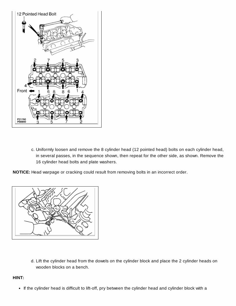
c. Uniformly loosen and remove the 8 cylinder head (12 pointed head) bolts on each cylinder head,in several passes, in the sequence shown, then repeat for the other side, as shown. Remove the16 cylinder head bolts and plate washers.
NOTICE: Head warpage or cracking could result from removing bolts in an incorrect order.
d. Lift the cylinder head from the dowels on the cylinder block and place the 2 cylinder heads onwooden blocks on a bench.
HINT:
If the cylinder head is difficult to liftoff, pry between the cylinder head and cylinder block with a

screwdriver.Arrange the cylinder heads in the correct order.
NOTICE: Be careful not to damage the contact surfaces of the cylinder head and cylinder block.