Embed Size (px)
Citation preview

2 III March 2014

www.ijraset.com Vol. 2 Issue III, March 2014
ISSN: 2321-9653
I N T E R N A T I O N A L J O U R N A L F O R R E S E A R C H I N A P P L I E D S C I E N C EAN D E N G I N E E R I N G T E C H N O L O G Y (I J R A S E T)
Page 143
Performance Improvement of Vacuum Pump Through CFD Analysis
Asst.Prof.R.L.Patel#1, Mr. Gopal Patel*2,Mr. K.N.Patel#3
#Department of Mechanical Engineering, C .U. Shah University, Gujarat, India.*Managing Director of Parag Engineering, Odhav GIDC Estate, Ahmedabad
*Department of Mechanical Engineering, Gujarat Technological University, Gujarat, India.
Abstract—In this study, water ring vacuum pump was numerically simulated and compared with experimentally measured data .To improve the efficiency of SUVAC V20 water ring vacuum pump, Computational Fluid Dynamics analysis is one of the advanced tool used in the pump industry. A detailed CFD analysis is used to predict the flow pattern inside the impeller which is an active pump component. Experimentally result of vacuum level of the pump is 450 mm of hg which is after CFD analysis 460 mm of hg, so deviation is 2.25% .So it is justified and validated with experiment result,therefore CFD analysis can use for further research for improvement in result of this WRVP.
Keywords—Computational fluid dynamic (CFD)analysis; Numerical simulation; Water ring vacuum pump(WRVP); Impeller; Validation
I. INTRODUCTIONA wide variety of water ring vacuum pump types have been constructed and used in many different applications in industry and other technical sectors. However, their design and performance prediction process is still a difficult task, mainly due to the great number of free geometric parameters,the effect of which cannot be directly evaluated. The significant cost and time of the trial-and-error process by constructing and testing physical prototypes reduces the profit margins of the pump manufacturers. For this reason CFD analysis is currently being used in the design and improvement performance of many pump types[1].
The experimental way of pump test can give the actual value of vacuum and its efficiency. But the internal flow conditions cannot be predicted by the experimental results. From the CFD analysis software and advanced post processing tools the complex flow inside the impeller can be analyzed. The complex flow characteristics cannot be visualized by the
experimental way of pump test. But in the case of CFD analysis the above flow characters can be visualized clearly. Moreover design modification can be done easily and thus CFD analysis reduces the product development time and cost.
In order to develop a reliable pump for this highly demanding operation, the behavior of the flow in the entire pump has to be predicted by a reliable computational method .Thenumerical simulation can provide quite accurate information on the fluid behavior in the pump, and thus helps the engineer to obtain a thorough performance evaluation of a particular design.Efficiency of the impeller can be improved by changing inlet outlet angle of the impeller blade and by increasing or decreasing the number of impeller blades. In this work, a water ring vacuum pump impeller will be analyzed to predict the internal flow and the impeller performance. Theresults of the predicted flow field in the pump impeller will be discussed.
II. WATER RING VACCUM PUMP MODELService liquid (usually water) is introduced into the WRVP. As the impeller rotates, centrifugal force creates a liquid ring which is concentric to the casing. At the inlet the area between the impeller blades increase in size, drawing gas in.As the impeller continues to rotate toward the discharge, the impeller bucket area decreases in size, compressing the air or gas. This gas, along with the liquid from the pump, is discharged through the outlet nozzle.
2.1 IMPELLER DESIGNImpeller layout is designed in order to meet the hydraulic characteristics of the pump to be designed. Impeller is the

www.ijraset.com Vol. 2 Issue III, March 2014
ISSN: 2321-9653
I N T E R N A T I O N A L J O U R N A L F O R R E S E A R C H I N A P P L I E D S C I E N C EAN D E N G I N E E R I N G T E C H N O L O G Y (I J R A S E T)
Page 144
important part of the vacuum pump as it displace the water and force it to form water ring as a result of which air is trapped between the cavity of formed between two successive blade and drawing further rotation vacuum is created in pump as the expansion of trapped air takes place.Pump efficiency is more dependent on impeller of pump. The main design parameters of the impeller of this water ring vacuum pump are: No. of blades 12, Rotation speed of impellers 2880 rpm , flow rate is 10 m3/hr, width of impeller is 26 mm.Basic design criteria of impeller consider here is tip speedwhich permissible for vacuum pump.
For calculation of diameter of impeller Permissible tip speed is 16 to 18 m/s.
Finally radius of impelleris 54 mm.
Thickness of blade is very important part in deciding suction capacity.Thickness of blade should be sufficient to accountthe pressure of water.So blade thickness is very important for designing impeller.Thickness of impeller blades is calculated by using empiricalrelation t = 0.05 to 0.09 R= 5 mmHeight of blade is calculated by following empirical relation h= 0.55 D= 59 mmActual eccentricity of impeller is given by 9 mm
We know that deep of blade in water (Dw)= actual eccentricityDw= 0.0090 mA= (b* Dw)= 0.00023 m2Force due to water pressure is calculated by following equation where water pressure p is taken as 1kg/cm2
Fw=P*AFw = 0.00023*1*104
Fw = 2.3 kg.fMax bending moment will be from following equation[2]B.M.= (1/3)*h*Fw= 0.044 kgf.mmSection modulus will be calculated from following equation[2] Z= (1/6)*b*t2=1*10-7 m3
Fig.1 Cavity of water ring vacuum pump
III. THE NUMERICAL SIMULATION OF WRVP
3.1MESHING OF WATER RING VACUUM PUMPThe mesh of twelve bladed water ring vacuum pump impeller domain is generated using Ansys Workbench. An unstructured mesh with tetrahedral cells is also used for the zones of impeller and body as shown in Fig.2.[4]

www.ijraset.com Vol. 2 Issue III, March 2014
ISSN: 2321-9653
I N T E R N A T I O N A L J O U R N A L F O R R E S E A R C H I N A P P L I E D S C I E N C EAN D E N G I N E E R I N G T E C H N O L O G Y (I J R A S E T)
Page 145
Fig.2 Meshing of WRVP
TABLE I
MESHING DETAIL OF WRVP
No. of Nodes 104035
No. of Elements 469681
Meshing Type 3D
Type of Element Tetrahedral
Fig.3 Meshing of impeller
To define impeller domain,domain type is solid domain fluid is Steel, motion is rotating and angular velocity is 2880 RPM is taken in fig.4
Fig.4 Impeller domain
For define Water Ring its domain type isfluid, domain fluid is water and domain motion is stationary in fig.5.
Fig.5 WRVP domain

www.ijraset.com Vol. 2 Issue III, March 2014
ISSN: 2321-9653
I N T E R N A T I O N A L J O U R N A L F O R R E S E A R C H I N A P P L I E D S C I E N C EAN D E N G I N E E R I N G T E C H N O L O G Y (I J R A S E T)
Page 146
3.2DEFINE HEAT TRANSFER AND TURBULENCE MODEL.Heat transfer model is total energy and turbulence Model is K-epsilon, Wherek is the turbulence kinetic energy and is defined as the variance of the fluctuations in velocity.The continuity Equation is then becomes
and the momentum equation becomes
Fig.6 Turbulence model
Fig.7 Interface in WRVP
IV. RESULTS OF ANALYSISFinally in process of numerical simulation after defining turbulence model and interface we get results In terms of pressure contour which is shown in fig.8.and we can see generated vaccum in fig.9.in fig 9 at inlet we get negative pressure and so we can see generated vaccum is 460 mm of hg. which is our result.
Fig.8 Pressure Contour
www.ijraset.com Vol. 2 Issue III, March 2014
ISSN: 2321-9653
I N T E R N A T I O N A L J O U R N A L F O R R E S E A R C H I N A P P L I E D S C I E N C EAN D E N G I N E E R I N G T E C H N O L O G Y (I J R A S E T)
Page 147
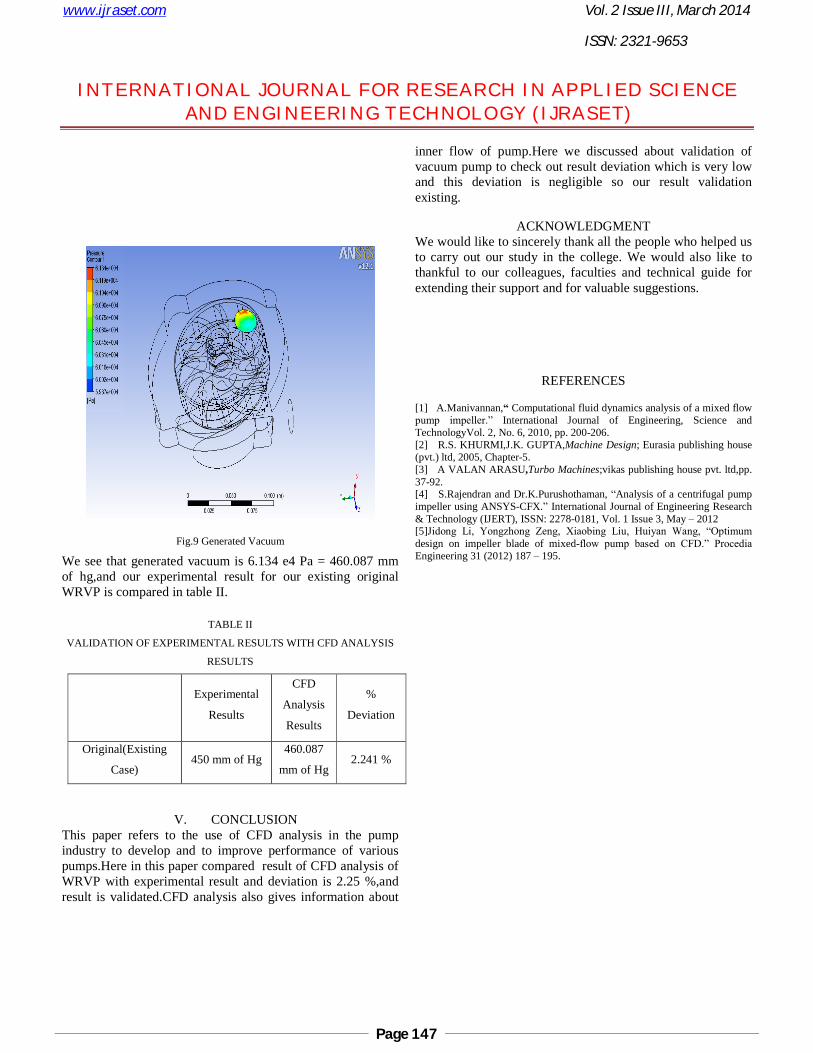
Fig.9 Generated Vacuum
We see that generated vacuum is 6.134 e4 Pa = 460.087 mm of hg,and our experimental result for our existing original WRVP is compared in table II.
TABLE II
VALIDATION OF EXPERIMENTAL RESULTS WITH CFD ANALYSIS
RESULTS
Experimental
Results
CFD
Analysis
Results
%
Deviation
Original(Existing
Case)450 mm of Hg
460.087
mm of Hg2.241 %
V. CONCLUSIONThis paper refers to the use of CFD analysis in the pump industry to develop and to improve performance of various pumps.Here in this paper compared result of CFD analysis of WRVP with experimental result and deviation is 2.25 %,and result is validated.CFD analysis also gives information about
inner flow of pump.Here we discussed about validation of vacuum pump to check out result deviation which is very low and this deviation is negligible so our result validation existing.
ACKNOWLEDGMENTWe would like to sincerely thank all the people who helped us to carry out our study in the college. We would also like to thankful to our colleagues, faculties and technical guide for extending their support and for valuable suggestions.
REFERENCES
[1] A.Manivannan,“ Computational fluid dynamics analysis of a mixed flow pump impeller.” International Journal of Engineering, Science and TechnologyVol. 2, No. 6, 2010, pp. 200-206. [2] R.S. KHURMI,J.K. GUPTA,Machine Design; Eurasia publishing house (pvt.) ltd, 2005, Chapter-5.[3] A VALAN ARASU,Turbo Machines;vikas publishing house pvt. ltd,pp. 37-92.[4] S.Rajendran and Dr.K.Purushothaman, “Analysis of a centrifugal pump impeller using ANSYS-CFX.” International Journal of Engineering Research & Technology (IJERT), ISSN: 2278-0181, Vol. 1 Issue 3, May – 2012[5]Jidong Li, Yongzhong Zeng, Xiaobing Liu, Huiyan Wang, “Optimum design on impeller blade of mixed-flow pump based on CFD.” Procedia Engineering 31 (2012) 187 – 195.