Embed Size (px)
Citation preview

44 Product overview • 2013 We reserve the right to change designs and technical specifications of our products.
Pressurisation and Expansion AutomatsFor large or tall sealed systems traditional expansion vessels are not the most effi cient solution in terms of operational pressure or physical footprint. Flamco Expansion Automats balance the system pressure, using a highly effi cient vessel design and control equipment.We produce a comprehensive range of models that offer high-quality performance and versatility which may be further enhanced by the addition of numerous optional accessories. This makes the Flamco expansion automats suitable for use in a variety of situations. As demands and preferences differ worldwide, Flamco has opted for an adaptable, modular range to suit every client’s requirements.
2.

45
Pressurisation and Expansion Automats
Product overview • 2013 We reserve the right to change designs and technical specifications of our products.
2
Pressurisation and Expansion AutomatsFor large or tall sealed systems traditional expansion vessels are not the most effi cient solution in terms of operational pressure or physical footprint. Flamco Expansion Automats balance the system pressure, using a highly effi cient vessel design and control equipment.We produce a comprehensive range of models that offer high-quality performance and versatility which may be further enhanced by the addition of numerous optional accessories. This makes the Flamco expansion automats suitable for use in a variety of situations. As demands and preferences differ worldwide, Flamco has opted for an adaptable, modular range to suit every client’s requirements.

46 Product overview • 2013 We reserve the right to change designs and technical specifications of our products.
Flexfiller Midi• Compact, fully-integrated wall
mounted topping-up and filling unit.• Max. operating pressure: 2.7 / 8.0
bar(g).• One or two pumps
(125D/150D/225D/250D).
Flexfiller Standard• Compact, fully-integrated free
standing topping-up and filling unit.• Max. operating pressure: 2.7 / 8.0
bar(g).• One or two pumps (125D/150D/
225D/250D/280DS/2100D).
Flexfiller Mini• Compact, fully-integrated topping-up
and filling unit.• Max. operating pressure: 3 bar(g).• One or two pumps (130D/230D).
Flexconpak• Cabinet Housed Packaged Sealed
System Set. • Pressurisation unit and Flexcon
expansion vessel included (integral).• One pump.
Basepak• Skid Mounted Packaged Sealed
System Set. • Flexfiller pressurisation unit, Flexcon
expansion vessel and connecting hose kit included.
• One pump.
Presspak• Digital Packaged Sealed System Set.• Presspak pressurisation unit,
Flexcon expansion vessel(s) and connecting hose kit included.
• One pump.
Flexfiller Twin System• Compact, fully-integrated topping-up
and filling unit for two systems.• Max. operating pressure: 2.7 / 8.0
bar(g).• One pump for each system (125D/150D/180DS).
Flexfill Plus• Compact, fully-integrated unit for
pressurisation and Pressure Step Degassing.
• Two microprocessors for independant control.
• Max. operating pressure: 6.0 / 8.0 bar(g).
• Two pumps (250D/280DS).
Packaged sealed system sets
Midifill Plus• Compact, fully-integrated unit for
pressurisation and Pressure Step Degassing.
• Two microprocessors for independant control.
• Max. operating pressure: 8.0 bar(g).• One pump (150D).
Pressurisation and Expansion Automats Overview
Pump-driven Refilling devicesCompressor-driven
Flamcomat• 150 - 10,000 litres.• Maximum operating pressure: 16 bar.• Maximum heating capacity: 12 MW.• Maximum cooling capacity: 24 MW.• Combined expansion,
de-aeration and topping-up device.• Available in models with one or two
pumps.
Flamco-Fill PE top-up device• For topping-up mains water in
sealed heating systems and for cool-ing systems with expansion vessels and devices.
• Power supply: 230 V / 50 - 60 Hz.• Maximum water main pressure:
10 bar.• Maximum system operating
pressure: 9 bar (PN 10).• Maximum operating temperature:
30 °C.
MVE 1 solenoid valve unit• Solenoid valve unit with maximum
vulhoeveelheid bewaking en min./Maximum pressure alarm for systems with expansion vessels or devices.
• With digital control, pressure sensor and ball valve.
• Maximum operating pressure: 10 bar.• Maximum operating temperature:
90 °C.• Power supply: 230 V / 50 Hz.
MVE 2 solenoid valve unit• Solenoid valve unit for systems with
devices with SPC/SCU control units or other 230 V top-up signal.
• With ball valve.• Maximum operating pressure: 10 bar.• Maximum operating temperature:
90 °C.
Flexfiller Glycol• Compact, fully-integrated topping-up
and filling unit.• Two tanks: a water tank and a
glycol tank. Glycol is introduced on demand
• Max. operating pressure: 2.5 / 5.0 bar(g).
• Two pumps (225D/250D).
M-K/C• 110 - 425 litres.• Maximum operating pressure: 6 bar.• Maximum heating capacity: 7 MW.• Maximum cooling capacity: 11 MW.• Expansion system with an SCU
control unit.
M-K/U• 400 - 3,500 litres.• Operating pressure: 6 / 10 bar.• Maximum heating capacity: 12 MW.• Maximum cooling capacity: 24 MW.• Expansion system with the
'next generation' SPC control unit.
M-K/S• 400 - 10,000 litres.• Maximum operating pressure:
3 / 6 / 10 bar.• Maximum heating capacity: 12 MW.• Maximum cooling capacity: 24 MW.• Extensive selection of compressors
and vessels.
Flexcon M-K auxiliary vessels• Maximum operating temperature
(at diaphragm): 70 °C (343 K) (EN13831/8).
• With removable butyl-rubber diaphragm.
• Vessels have adjustable foot height.• Exclusive air-side connection
between the vessel (and control unit) and the additional vessel, using a pressure hose. The water-side connection must be made in situ.
NFE 1 refill unit• Comprises a BA reflux guard, water
meter, dirt filter, ball valve and non-return valve.
• Maximum operating pressure: 10 bar.• Maximum operating temperature:
65 °C.
NFE 2 refill unit• Comprises a water meter, dirt filter,
ball valve and non-return valve.• Maximum operating pressure: 10 bar.• Maximum operating temperature:
90 °C.
NFE 3 refill unit• Comprises a dirt filter, ball valve and
non-return valve.• Maximum operating pressure: 10 bar.• Maximum operating temperature:
90 °C.
Flexcon MPR-S• Pressure range: 16 - 25 bar.• Maximum heating capacity: 0.9 MW.• Maximum cooling capacity: 6.1 MW.• Combined expansion and
topping-up device.• Available in models with one or two
pumps.

47
Pressurisation and Expansion Automats
Product overview • 2013 We reserve the right to change designs and technical specifications of our products.
2
Flexfiller Midi• Compact, fully-integrated wall
mounted topping-up and filling unit.• Max. operating pressure: 2.7 / 8.0
bar(g).• One or two pumps
(125D/150D/225D/250D).
Flexfiller Standard• Compact, fully-integrated free
standing topping-up and filling unit.• Max. operating pressure: 2.7 / 8.0
bar(g).• One or two pumps (125D/150D/
225D/250D/280DS/2100D).
Flexfiller Mini• Compact, fully-integrated topping-up
and filling unit.• Max. operating pressure: 3 bar(g).• One or two pumps (130D/230D).
Flexconpak• Cabinet Housed Packaged Sealed
System Set. • Pressurisation unit and Flexcon
expansion vessel included (integral).• One pump.
Basepak• Skid Mounted Packaged Sealed
System Set. • Flexfiller pressurisation unit, Flexcon
expansion vessel and connecting hose kit included.
• One pump.
Presspak• Digital Packaged Sealed System Set.• Presspak pressurisation unit,
Flexcon expansion vessel(s) and connecting hose kit included.
• One pump.
Flexfiller Twin System• Compact, fully-integrated topping-up
and filling unit for two systems.• Max. operating pressure: 2.7 / 8.0
bar(g).• One pump for each system (125D/150D/180DS).
Flexfill Plus• Compact, fully-integrated unit for
pressurisation and Pressure Step Degassing.
• Two microprocessors for independant control.
• Max. operating pressure: 6.0 / 8.0 bar(g).
• Two pumps (250D/280DS).
Packaged sealed system sets
Midifill Plus• Compact, fully-integrated unit for
pressurisation and Pressure Step Degassing.
• Two microprocessors for independant control.
• Max. operating pressure: 8.0 bar(g).• One pump (150D).
Pressurisation and Expansion Automats Overview
Pump-driven Refilling devicesCompressor-driven
Flamcomat• 150 - 10,000 litres.• Maximum operating pressure: 16 bar.• Maximum heating capacity: 12 MW.• Maximum cooling capacity: 24 MW.• Combined expansion,
de-aeration and topping-up device.• Available in models with one or two
pumps.
Flamco-Fill PE top-up device• For topping-up mains water in
sealed heating systems and for cool-ing systems with expansion vessels and devices.
• Power supply: 230 V / 50 - 60 Hz.• Maximum water main pressure:
10 bar.• Maximum system operating
pressure: 9 bar (PN 10).• Maximum operating temperature:
30 °C.
MVE 1 solenoid valve unit• Solenoid valve unit with maximum
vulhoeveelheid bewaking en min./Maximum pressure alarm for systems with expansion vessels or devices.
• With digital control, pressure sensor and ball valve.
• Maximum operating pressure: 10 bar.• Maximum operating temperature:
90 °C.• Power supply: 230 V / 50 Hz.
MVE 2 solenoid valve unit• Solenoid valve unit for systems with
devices with SPC/SCU control units or other 230 V top-up signal.
• With ball valve.• Maximum operating pressure: 10 bar.• Maximum operating temperature:
90 °C.
Flexfiller Glycol• Compact, fully-integrated topping-up
and filling unit.• Two tanks: a water tank and a
glycol tank. Glycol is introduced on demand
• Max. operating pressure: 2.5 / 5.0 bar(g).
• Two pumps (225D/250D).
M-K/C• 110 - 425 litres.• Maximum operating pressure: 6 bar.• Maximum heating capacity: 7 MW.• Maximum cooling capacity: 11 MW.• Expansion system with an SCU
control unit.
M-K/U• 400 - 3,500 litres.• Operating pressure: 6 / 10 bar.• Maximum heating capacity: 12 MW.• Maximum cooling capacity: 24 MW.• Expansion system with the
'next generation' SPC control unit.
M-K/S• 400 - 10,000 litres.• Maximum operating pressure:
3 / 6 / 10 bar.• Maximum heating capacity: 12 MW.• Maximum cooling capacity: 24 MW.• Extensive selection of compressors
and vessels.
Flexcon M-K auxiliary vessels• Maximum operating temperature
(at diaphragm): 70 °C (343 K) (EN13831/8).
• With removable butyl-rubber diaphragm.
• Vessels have adjustable foot height.• Exclusive air-side connection
between the vessel (and control unit) and the additional vessel, using a pressure hose. The water-side connection must be made in situ.
NFE 1 refill unit• Comprises a BA reflux guard, water
meter, dirt filter, ball valve and non-return valve.
• Maximum operating pressure: 10 bar.• Maximum operating temperature:
65 °C.
NFE 2 refill unit• Comprises a water meter, dirt filter,
ball valve and non-return valve.• Maximum operating pressure: 10 bar.• Maximum operating temperature:
90 °C.
NFE 3 refill unit• Comprises a dirt filter, ball valve and
non-return valve.• Maximum operating pressure: 10 bar.• Maximum operating temperature:
90 °C.
Flexcon MPR-S• Pressure range: 16 - 25 bar.• Maximum heating capacity: 0.9 MW.• Maximum cooling capacity: 6.1 MW.• Combined expansion and
topping-up device.• Available in models with one or two
pumps.

48 Product overview • 2013 We reserve the right to change designs and technical specifications of our products.
10
FLAMC 1273
20 30 40 50 60 70 80 90 100 110 120
1
0
2
3
4
5
6
Temperature [°C]
Incr
ease
in v
olum
e [%
]
Flamcomat selection graph. Typical heating installation (nominal characteristics)
Flamcomat Pump Curves
Boiler output [MW]
Nominal flow rate [m³/h]
Nominal flow rate [m³/h]
Basic Concepts for the Calculation of Expansion Automats
To select the right expansion automat it is necessary to understand the following principles:
• Static height This is the height of the system between the connection of the Flexcon expansion appliance and the highest point, measured in water column metres (1 wcm = 0.1 bar).
Sizing Expansion Automats• System water capacity
This is the total volume of water in the entire system including heat source, radiators, pipe work etc.
• Increase in water volume (in %) The table below shows the percentage volume increase of water as temperature increases from 10 °C to 110 °C.
• Expansion volume The expansion volume is determined in the following way: expansion volume = capacity x increase in volume at the average heating temperature.
Example: heating temperature 90/70 °C (average 80 °C) = 2.89%.
• Heating/Cooling power This is the sum of the nominal heating capacities.
• Capacity of the expansion automat The capacity of a pump expansion automat is determined in the following way: capacity of expansion appliance = 1.3 x expansion volume (in the case of the Flexcon M-K / C the factor is 1.4).
The factor of 1.3 is based on the following assumptions:• The expansion vessel has to hold at least 10%
more than the calculated expansion volume.• The volume of the vessel allows for refilling
and min./max. levels.• Corrections to tolerances which, according to
various standards, are admissible for parts of the system.
FlExCon M-K / U
Set s
yste
m p
ress
ure
[bar
]
Heating capacity [MW]
2 x K-042
1 x K-0421 x K-041 x K-03
1 x K-021 x K/C
2 x K-02
2 x K-04
2 x K-03
PN16
PN6
PN10
10
9
8
7
6
5
4
3
2
1
0
0 1 2 3 4 5 6 7 8 9 10 11 12
Flexcon M-K Compressor CurvesFlexcon M-K selection graph. Typical heating installation (nominal characteristics)
Increase in temperature [°C]
Increase in volume[%]
10 - 25 0.3510 - 30 0.4310 - 35 0.6310 - 40 0.7510 - 45 0.9610 - 50 1.1810 - 55 1.4210 - 60 1.6810 - 70 2.2510 - 80 2.8910 - 90 3.5810 - 100 4.3410 - 110 5.16
Syst
em s
et p
ress
ure,
wor
king
pre
ssur
e [b
ar]
Syst
em s
et p
ress
ure
= P
stat
ic h
eigh
t +
Pvap
our+
Ppo
s+ (0
.3 ..
. 0.5
bar
)

49
Pressurisation and Expansion Automats
Product overview • 2013 We reserve the right to change designs and technical specifications of our products.
2
10
FLAMC 1273
20 30 40 50 60 70 80 90 100 110 120
1
0
2
3
4
5
6
Temperature [°C]
Incr
ease
in v
olum
e [%
]
Flamcomat selection graph. Typical heating installation (nominal characteristics)
Flamcomat Pump Curves
Boiler output [MW]
Nominal flow rate [m³/h]
Nominal flow rate [m³/h]
Basic Concepts for the Calculation of Expansion Automats
To select the right expansion automat it is necessary to understand the following principles:
• Static height This is the height of the system between the connection of the Flexcon expansion appliance and the highest point, measured in water column metres (1 wcm = 0.1 bar).
Sizing Expansion Automats• System water capacity
This is the total volume of water in the entire system including heat source, radiators, pipe work etc.
• Increase in water volume (in %) The table below shows the percentage volume increase of water as temperature increases from 10 °C to 110 °C.
• Expansion volume The expansion volume is determined in the following way: expansion volume = capacity x increase in volume at the average heating temperature.
Example: heating temperature 90/70 °C (average 80 °C) = 2.89%.
• Heating/Cooling power This is the sum of the nominal heating capacities.
• Capacity of the expansion automat The capacity of a pump expansion automat is determined in the following way: capacity of expansion appliance = 1.3 x expansion volume (in the case of the Flexcon M-K / C the factor is 1.4).
The factor of 1.3 is based on the following assumptions:• The expansion vessel has to hold at least 10%
more than the calculated expansion volume.• The volume of the vessel allows for refilling
and min./max. levels.• Corrections to tolerances which, according to
various standards, are admissible for parts of the system.
FlExCon M-K / U
Set s
yste
m p
ress
ure
[bar
]
Heating capacity [MW]
2 x K-042
1 x K-0421 x K-041 x K-03
1 x K-021 x K/C
2 x K-02
2 x K-04
2 x K-03
PN16
PN6
PN10
10
9
8
7
6
5
4
3
2
1
0
0 1 2 3 4 5 6 7 8 9 10 11 12
Flexcon M-K Compressor CurvesFlexcon M-K selection graph. Typical heating installation (nominal characteristics)
Increase in temperature [°C]
Increase in volume[%]
10 - 25 0.3510 - 30 0.4310 - 35 0.6310 - 40 0.7510 - 45 0.9610 - 50 1.1810 - 55 1.4210 - 60 1.6810 - 70 2.2510 - 80 2.8910 - 90 3.5810 - 100 4.3410 - 110 5.16
Syst
em s
et p
ress
ure,
wor
king
pre
ssur
e [b
ar]
Syst
em s
et p
ress
ure
= P
stat
ic h
eigh
t +
Pvap
our+
Ppo
s+ (0
.3 ..
. 0.5
bar
)

50 Product overview • 2013 We reserve the right to change designs and technical specifications of our products.
Calculations for Expansion Automats in Heating Installations
ExAmplE 1
DATA- heating power = 1,500 kW- average heating temperature (90/70 ºC) = 80 ºC- static height = 20 metres- system volume = 15,400 litres- provision for expansion (vessel) situated at the bottom of the system.
CAlCUlATION OF VESSEl CApACITYIncrease in volume in % = 2.89% ≈ 2.9%
15,400 x 2.9Expansion volume = ––––––––––––– = 447 litres 100
Required expansion reservoir capacity = 447 x 1.3 = 581 litres
YOUR CHOICEAlternative I : Flamcomat GB 600. Calculation - control unit with pump. Nominal operating pressure = 2 + 1 = 3 bar. The 1.5 MW - 3 bar point is under the M 02 pump curve (see Flamcomat pump characteristics graph). Selected: Flamcomat GB 600/m 02.
Alternative II : m-K/U 600, 6 bar model, possibly in combination with an ENA 20 de-aeration appliance.
ExAmplE 2
DATA- heating power = 7,000 kW- average heating temperature (70/40ºC) = 55 ºC- static height = 37 metres- system volume = unknown- provision for expansion (vessel) situated at the bottom of the system.- system components: mixed utility.
CAlCUlATION OF VESSEl CApACITYSystem capacity calculation = 7,000 x 10 = 70,000 litresIncrease in volume in % = 1.42%
7,000 x 1.42Expansion volume = ––––––––––– = 994 litres 100Required expansion reservoir capacity = 994 x 1.3 = 1,292 litres
YOUR CHOICE Alternative I : Flamcomat GB 1600. Calculation - control unit with pump. Nominal operating pressure = 3.7 + 1 = 4.7 bar. The 7 MW - 4.7 bar point is on the D 20 group curve (see Flamcomat pump characteristics graph). Selected: Flamcomat GB 1600/D 20.
Alternative II : m-K/U 1600, 6 bar model, possibly in combination with an ENA 30 de-aeration appliance.
Calculation for Expansion Automats in Chilled Water Systems
ExAmplE 1
DATA- heating power = 5,400 kW- system volume = 95,000 litres- static height = < 5 metres (with vessel above)- temperature (6/12 ºC) = 9 °C- max. ambient temperature = 30 °C- no glycol
CAlCUlATION OF VESSEl CApACITYIncrease in volume at 30 °C, without glycol = 0.43%
95,000 x 0.43Expansion volume = ––––––––––––– = 409 litres 100Required expansion reservoir capacity = 409 x 1.3 = 531 litres
YOUR CHOICEAlternative I : Flexcon m-K/U 600, 6 bar model, possibly in combination with an ENA 10 de-aeration appliance.
Alternative II : Calculation - control unit with pump. Nominal operating pressure = 0.5 + 1 = 1.5 bar. As the selection table shows heat capacity, the aforementioned cooling capacity will have to be converted using a conversion factor of 0.412. The selection point is then 5,400 kW x 0.412 = 2,225 kW (2.2 MW) and 1.5 bar. The 2.2 MW - 1.5 bar point is on the M 02 pump curve (see Flamcomat pump characteristics graph). Selected: Flamcomat GB 600/m 02.

51
Pressurisation and Expansion Automats
Product overview • 2013 We reserve the right to change designs and technical specifications of our products.
2
Calculations for Expansion Automats in Heating Installations
ExAmplE 1
DATA- heating power = 1,500 kW- average heating temperature (90/70 ºC) = 80 ºC- static height = 20 metres- system volume = 15,400 litres- provision for expansion (vessel) situated at the bottom of the system.
CAlCUlATION OF VESSEl CApACITYIncrease in volume in % = 2.89% ≈ 2.9%
15,400 x 2.9Expansion volume = ––––––––––––– = 447 litres 100
Required expansion reservoir capacity = 447 x 1.3 = 581 litres
YOUR CHOICEAlternative I : Flamcomat GB 600. Calculation - control unit with pump. Nominal operating pressure = 2 + 1 = 3 bar. The 1.5 MW - 3 bar point is under the M 02 pump curve (see Flamcomat pump characteristics graph). Selected: Flamcomat GB 600/m 02.
Alternative II : m-K/U 600, 6 bar model, possibly in combination with an ENA 20 de-aeration appliance.
ExAmplE 2
DATA- heating power = 7,000 kW- average heating temperature (70/40ºC) = 55 ºC- static height = 37 metres- system volume = unknown- provision for expansion (vessel) situated at the bottom of the system.- system components: mixed utility.
CAlCUlATION OF VESSEl CApACITYSystem capacity calculation = 7,000 x 10 = 70,000 litresIncrease in volume in % = 1.42%
7,000 x 1.42Expansion volume = ––––––––––– = 994 litres 100Required expansion reservoir capacity = 994 x 1.3 = 1,292 litres
YOUR CHOICE Alternative I : Flamcomat GB 1600. Calculation - control unit with pump. Nominal operating pressure = 3.7 + 1 = 4.7 bar. The 7 MW - 4.7 bar point is on the D 20 group curve (see Flamcomat pump characteristics graph). Selected: Flamcomat GB 1600/D 20.
Alternative II : m-K/U 1600, 6 bar model, possibly in combination with an ENA 30 de-aeration appliance.
Calculation for Expansion Automats in Chilled Water Systems
ExAmplE 1
DATA- heating power = 5,400 kW- system volume = 95,000 litres- static height = < 5 metres (with vessel above)- temperature (6/12 ºC) = 9 °C- max. ambient temperature = 30 °C- no glycol
CAlCUlATION OF VESSEl CApACITYIncrease in volume at 30 °C, without glycol = 0.43%
95,000 x 0.43Expansion volume = ––––––––––––– = 409 litres 100Required expansion reservoir capacity = 409 x 1.3 = 531 litres
YOUR CHOICEAlternative I : Flexcon m-K/U 600, 6 bar model, possibly in combination with an ENA 10 de-aeration appliance.
Alternative II : Calculation - control unit with pump. Nominal operating pressure = 0.5 + 1 = 1.5 bar. As the selection table shows heat capacity, the aforementioned cooling capacity will have to be converted using a conversion factor of 0.412. The selection point is then 5,400 kW x 0.412 = 2,225 kW (2.2 MW) and 1.5 bar. The 2.2 MW - 1.5 bar point is on the M 02 pump curve (see Flamcomat pump characteristics graph). Selected: Flamcomat GB 600/m 02.

52 Product overview • 2013 We reserve the right to change designs and technical specifications of our products.
The Flexcon M-K/U compressor expansion automats store the expansion water from the system. They also hold the system pressure at the pre-set level within clearly defined limits. Water and compressed air are separated from each other by a removable high-quality butyl-rubber bladder which has a high diffusion density (low gas permeability).
Noticeable features of the Flexcon M-K/U are the high level of reliability and sturdiness. The Flexcon M-K/U is adaptable to a wide range of situations and there are plenty of optional accessories which mean that it can be put to many different uses in countless systems. They are low-noise compressors that require no oil.
The entirely micro-processor driven control unit in the Flexcon M-K/U expansion automat has a number of parameters that can be set to any variable within a given range.
The benefits of the Flexcon M-K/U• Stable system pressure and a large working vessel
volume.• With red epoxy-powder coating.• Easy to install and commission.• Intuitieve SPC controller. This is a 'plug and
play' control system including clear instructions via the sensor touch screen, intuitive and easy to use with economic energy-save mode.
Flexcon M-K/U, the reliable compressor expansion automat
Flexcon M-K/U(SPC-control unit).
Solenoid valve assembly.
Compressor.
Exchangeable bladder of high-quality butyl-rubber.
Weight/capacity sensor.
1. ColdThe automat contains a small amount of water. The automat is at rest.
3. Full powerBy storing increasing amounts of water in the vessel the controller keeps the system pressure at a constant level. When the system has warmed up completely, the vessel will be almost full to capacity.
2. Warming upThe volume of water, and thus the system pressure, increases.The controller responds to this by discharging air from the vessel and, as a result, the expansion water flows into the bladder.
4. Cooling downWhen the volume of water and thus the system pressure decreases, the controller will respond by increasing the air-pressure in the vessel with displacement of water back into the system as a result. This restores equilibrium in the system pressure.
FLEXCON M-K/U
Foot-height adjuster for leveling.

53
Pressurisation and Expansion Automats
Product overview • 2013 We reserve the right to change designs and technical specifications of our products.
2
The Flexcon M-K/U compressor expansion automats store the expansion water from the system. They also hold the system pressure at the pre-set level within clearly defined limits. Water and compressed air are separated from each other by a removable high-quality butyl-rubber bladder which has a high diffusion density (low gas permeability).
Noticeable features of the Flexcon M-K/U are the high level of reliability and sturdiness. The Flexcon M-K/U is adaptable to a wide range of situations and there are plenty of optional accessories which mean that it can be put to many different uses in countless systems. They are low-noise compressors that require no oil.
The entirely micro-processor driven control unit in the Flexcon M-K/U expansion automat has a number of parameters that can be set to any variable within a given range.
The benefits of the Flexcon M-K/U• Stable system pressure and a large working vessel
volume.• With red epoxy-powder coating.• Easy to install and commission.• Intuitieve SPC controller. This is a 'plug and
play' control system including clear instructions via the sensor touch screen, intuitive and easy to use with economic energy-save mode.
Flexcon M-K/U, the reliable compressor expansion automat
Flexcon M-K/U(SPC-control unit).
Solenoid valve assembly.
Compressor.
Exchangeable bladder of high-quality butyl-rubber.
Weight/capacity sensor.
1. ColdThe automat contains a small amount of water. The automat is at rest.
3. Full powerBy storing increasing amounts of water in the vessel the controller keeps the system pressure at a constant level. When the system has warmed up completely, the vessel will be almost full to capacity.
2. Warming upThe volume of water, and thus the system pressure, increases.The controller responds to this by discharging air from the vessel and, as a result, the expansion water flows into the bladder.
4. Cooling downWhen the volume of water and thus the system pressure decreases, the controller will respond by increasing the air-pressure in the vessel with displacement of water back into the system as a result. This restores equilibrium in the system pressure.
FLEXCON M-K/U
Foot-height adjuster for leveling.

54 Product overview • 2013 We reserve the right to change designs and technical specifications of our products.
FLEXCON M-K/U COMPRESSOR EXPANSION AUTOMAT
For heating and chilled water (cooling) installations.
Ideal for larger systems and systems which cannot tolerate the rise in pressure associated with standard sealed system equipment.
These units are distinguished by their wide range of applications. Installation is both simple and cost-effective due to the adjustable system connection and the fact that the systems come complete and ready to operate. The unit is combined with the latest technology SPC control unit.Compact, space saving unit, which has a low noise, oil free compressor. This compressor expansion automat has a simple and clear control panel which can be connected to a building management system or system monitoring device.
•Replaceable bladder.• Internally uncoated (internal coating available to special order).•Red (RAL 3002) epoxy powder coating.•Maximum temperature on bladder (EN 13831/8): 70 °C.•Min. temperature at (heating) outlet: 0 °C.• In accordance with European Pressure Equipment Directive 97/23/EC.•Material quality:
- ASTM/ISO: A181 class 60 / S235JRG2. - EN/ISO: P245N.
Flexcon M-K/U - 6.0 bar
•Maximum operating pressure: 5.2 bar, design pressure PN 6.
Type Capa-city[l]
Dimensions Com-pressor
Syst.conn.ISO
228-1(F)
Weight[kg]
OrderCode
Ø[mm]
H.[mm]
Flexcon M-K/U 400 400 750 1369 K-011 G 1 1/4" 153 1 23824Flexcon M-K/U 600 600 750 1789 K-011 G 1 1/4" 183 1 23826Flexcon M-K/U 800 800 750 2189 K-031 G 1 1/4" 218 1 23828Flexcon M-K/U 1000 1000 750 2689 K-031 G 1 1/2" 253 1 23830Flexcon M-K/U 1200 1200 1000 2025 K-031 G 1 1/2" 313 1 23832Flexcon M-K/U 1600 1600 1000 2525 K-031 G 1 1/2" 368 1 23836Flexcon M-K/U 2000 2000 1200 2277 K-031 G 2 1/2" 453 1 23840Flexcon M-K/U 2800 2800 1200 2877 K-031 G 2 1/2" 538 1 23848Flexcon M-K/U 3500 3500 1200 3677 K-031 G 2 1/2" 648 1 23855
Flexcon M-K/U - 10.0 bar
•Maximum operating pressure: 8.0 bar, design pressure PN 10.
Type Capa-city[l]
Dimensions Com-pressor
Syst.conn.ISO
228-1(F)
Weight[kg]
OrderCode
Ø[mm]
H.[mm]
Flexcon M-K/U 400 400 750 1369 K-011 G 1 1/4" 188 1 23864Flexcon M-K/U 600 600 750 1789 K-011 G 1 1/4" 228 1 23866Flexcon M-K/U 800 800 750 2189 K-031 G 1 1/4" 258 1 23868Flexcon M-K/U 1000 1000 750 2689 K-031 G 1 1/2" 308 1 23870Flexcon M-K/U 1200 1200 1000 2025 K-031 G 1 1/2" 418 1 23872Flexcon M-K/U 1600 1600 1000 2525 K-031 G 1 1/2" 508 1 23876Flexcon M-K/U 2000 2000 1200 2277 K-031 G 2" 618 1 23880Flexcon M-K/U 2800 2800 1200 2877 K-031 G 2 1/2" 785 1 23888Flexcon M-K/U 3500 3500 1200 3675 K-031 G 2 1/2" 938 1 23895

55
Pressurisation and Expansion Automats
Product overview • 2013 We reserve the right to change designs and technical specifications of our products.
2
FLEXCON M-K/C COMPRESSOR EXPANSION AUTOMAT
For smaller heating and chilled water (cooling) installations.
Thisproductisespeciallydesignedforsmallercommercialsystemswithlimitedspace,providingallthebenefitsofanautomatatan affordable price.
• Diaphragm:Fixedflexiblerubberdiaphragmwithrollingaction.•Suitable for addition of glycol-based anti-freeze up to 50%.•Red (RAL 3002) epoxy powder coating.•Maximum temperature on diaphragm (EN 13831/8): 70 °C.•Min. temperature at (heating) outlet: -10 °C.• In accordance with European Pressure Equipment Directive 97/23/EC.•Material quality:
- S235JRG2 / EN10025.
For stand-alone applications only.
Flexcon M-K/C - 6.0 bar
•Maximum operating pressure: 5.2 bar, design pressure PN 6.
Type Capa-city[l]
Dimensions Com-pressor
Syst.conn.ISO
228-1(F)
Weight[kg]
OrderCode
Ø[mm]
H.[mm]
Flexcon M-K/C 110 110 509 1215 K/C G1" 37 1 23225Flexcon M-K/C 200 200 600 1391 K/C G1" 71 1 23226Flexcon M-K/C 350 350 790 1459 K/C G1" 81 1 23227Flexcon M-K/C 425 425 790 1612 K/C G1" 91 1 23228
Nr. 0343

56 Product overview • 2013 We reserve the right to change designs and technical specifications of our products.
FLEXCON M-K/S COMPRESSOR EXPANSION AUTOMAT
For heating and chilled water (cooling) installations.
HighefficiencyunitswithFlexconSmicroprocessorcontrolunitdesignedtooperateheatingandairconditioningsystemsataconstant pressure. Ideal for larger systems and systems which cannot tolerate the rise in pressure associated with standard sealed system equipment.
These units are distinguished by their wide range of applications. Installation is both simple and cost effective due to the adjustable system connection and the fact that the systems come complete and ready to operate. Installation parameters are programmed before operation.Compact, space saving unit, which has a low noise, oil free compressor. This compressor unit has a simple and clear control panel which can be connected to a building management system or system monitoring device.
•Replaceable bladder.•Red (RAL 3002) epoxy powder coating.•Maximum temperature on bladder (EN 13831/8): 70 °C.•Min. temperature at (heating) outlet: 0 °C.• In accordance with Pressure Equipment Directive 97/23/EC.•Material quality: - ASTM/ISO: A181 class 60 / S235JRG2. - EN/ISO: P245N.
Flexcon S control unit is capable of operating together with up to 2 other controllers in the same system. Details on request.
Flexcon M-K/S - 3.0 bar
•Maximum operating pressure: 2.4 bar, design pressure PN 3.
Type Capa-city[l]
Dimensions Com-pressor
Syst.conn.
ISO 228-1(F)
Weight[kg]
OrderCode
Ø[mm]
H.[mm]
Flexcon M-K/S 5000 5000 1500 3550 K-031 Rp 1 1/2" 976 1 23858Flexcon M-K/S 6500 6500 1800 3465 K-031 Rp 1 1/2" 1476 1 23859Flexcon M-K/S 8000 8000 1900 3565 K-031 Rp 1 1/2" 1581 1 23860Flexcon M-K/S 10000 10000 2000 3985 K-031 Rp 1 1/2" 1821 1 23861

57
Pressurisation and Expansion Automats
Product overview • 2013 We reserve the right to change designs and technical specifications of our products.
2
Flexcon M-K/S - 6.0 bar
•Maximum operating pressure: 5.2 bar, design pressure PN 6.
Type Capa-city[l]
Dimensions Com-pressor
Syst.conn.
ISO 228-1(F)
Weight[kg]
OrderCode
Ø[mm]
H.[mm]
Flexcon M-K/S 400 400 750 1369 K-011 G 1 1/2" 153 1 22901Flexcon M-K/S 400 400 750 1369 K-031 G 1 1/2" 153 1 22903Flexcon M-K/S 400 400 750 1369 K- 04 G 1 1/2" 170 1 22906Flexcon M-K/S 600 600 750 1789 K-011 1 1/4" 186 1 22907Flexcon M-K/S 600 600 750 1789 K-031 G 1 1/2" 189 1 22909Flexcon M-K/S 600 600 750 1789 K- 04 G 1 1/2" 200 1 22911Flexcon M-K/S 800 800 750 2189 K-011 G 1 1/2" 221 1 22912Flexcon M-K/S 800 800 750 2189 K-031 G 1 1/2" 224 1 22914Flexcon M-K/S 800 800 750 2189 K- 04 G 1 1/2" 235 1 22916Flexcon M-K/S 1000 1000 750 2689 K-011 G 1 1/2" 256 1 22917Flexcon M-K/S 1000 1000 750 2689 K-031 G 1 1/2" 259 1 22919Flexcon M-K/S 1000 1000 750 2689 K- 04 G 1 1/2" 270 1 22921Flexcon M-K/S 1200 1200 1000 2025 K-011 G 1 1/2" 316 1 22922Flexcon M-K/S 1200 1200 1000 2025 K-031 G 1 1/2" 319 1 22924Flexcon M-K/S 1200 1200 1000 2025 K- 04 G 1 1/2" 330 1 22926Flexcon M-K/S 1600 1600 1000 2277 K-031 G 1 1/2" 374 1 22929Flexcon M-K/S 1600 1600 1000 2525 K- 04 G 1 1/2" 385 1 22931Flexcon M-K/S 2000 2000 1200 2277 K-031 G 2" 459 1 22934Flexcon M-K/S 2000 2000 1200 2277 K- 04 G 2" 470 1 22936Flexcon M-K/S 2800 2800 1200 2877 K-031 G 2 1/2" 544 1 22939Flexcon M-K/S 2800 2800 1200 2877 K- 04 G 2 1/2" 555 1 22941Flexcon M-K/S 3500 3500 1200 3677 K-031 G 2 1/2" 654 1 22944Flexcon M-K/S 3500 3500 1200 3677 K- 04 G 2 1/2" 665 1 22946
Flexcon M-K/S - 10.0 bar
•Maximum operating pressure: 8.0 bar (with K-04: 8.8 bar), design pressure PN 10.
Type Capa-city[l]
Dimensions Com-pressor
Syst.conn.
ISO 228-1(F)
Weight[kg]
OrderCode
Ø[mm]
H.[mm]
Flexcon M-K/S 400 400 750 1369 K-011 G 1 1/2" 201 1 22950Flexcon M-K/S 400 400 750 1369 K-031 G 1 1/2" 204 1 22952Flexcon M-K/S 400 400 750 1369 K- 04 G 1 1/2" 215 1 22954Flexcon M-K/S 600 600 750 1789 K-011 G 1 1/2" 241 1 22955Flexcon M-K/S 600 600 750 1789 K-031 G 1 1/2" 244 1 22957Flexcon M-K/S 600 600 750 1789 K- 04 G 1 1/2" 255 1 22959Flexcon M-K/S 800 800 750 2189 K-011 G 1 1/2" 291 1 22960Flexcon M-K/S 800 800 750 2189 K-031 G 1 1/2" 294 1 22962Flexcon M-K/S 800 800 750 2189 K- 04 G 1 1/2" 305 1 22964Flexcon M-K/S 1000 1000 750 2689 K-011 G 1 1/2" 331 1 22965Flexcon M-K/S 1000 1000 750 2689 K-031 G 1 1/2" 334 1 22967Flexcon M-K/S 1000 1000 750 2689 K- 04 G 1 1/2" 345 1 22969Flexcon M-K/S 1200 1200 1000 2025 K-011 G 1 1/2" 441 1 22970Flexcon M-K/S 1200 1200 1000 2025 K-031 G 1 1/2" 444 1 22972Flexcon M-K/S 1200 1200 1000 2025 K- 04 G 1 1/2" 455 1 22974Flexcon M-K/S 1600 1600 1000 2525 K-031 G 1 1/2" 519 1 22977Flexcon M-K/S 1600 1600 1000 2525 K- 04 G 1 1/2" 530 1 22979Flexcon M-K/S 2000 2000 1200 2277 K-031 G 2" 634 1 22982Flexcon M-K/S 2000 2000 1200 2277 K- 04 G 2" 645 1 22984Flexcon M-K/S 2800 2800 1200 2877 K-031 G 2 1/2" 759 1 22987Flexcon M-K/S 2800 2800 1200 2877 K- 04 G 2 1/2" 770 1 22989Flexcon M-K/S 3500 3500 1200 3677 K-031 G 2 1/2" 934 1 22992Flexcon M-K/S 3500 3500 1200 3677 K- 04 G 2 1/2" 945 1 22994

58 Product overview • 2013 We reserve the right to change designs and technical specifications of our products.
EXTRA COMPRESSORS
The second compressor unit is assembled on a second console on the Flexcon M-K/S or M-K/U compressor expansion automat. Both compressors must be of equal capacity and type. Delivered complete, assembled and ready for use.
Note:Thisconfigurationcomeswithfailurechangeoveroperationoptiononly.
Second Compressor Unit
Type Application OrderCode
Compressor K-011 Flexcon M-K/S & M-K/U 1 23618Compressor K-031 Flexcon M-K/S & M-K/U 1 23620Compressor K-04 Flexcon M-K/S & M-K/U 1 23621
FLEXCON M-K AUXILIARY VESSELS
For heating and chilled water (cooling) installations.
•Without control unit.•Replaceable bladder.•Red (RAL 3002) epoxy powder coating.•Maximum temperature on bladder (EN 13831/8): 70 °C.•Min. temperature at (heating) outlet: 0 °C.• In accordance with Pressure Equipment Directive 97/23/EC.•Material quality: - ASTM/ISO: A181 class 60 / S235JRG2. - EN/ISO: P245N.
Flanges as per DIN 2633 PN 16 with adapter available (to be ordered separately).
Flexcon M-K - 3.0 bar
•Design pressure: PN 3.
Type Capa-city[l]
Dimensions Syst.conn.
ISO 228-1(F)
Weight[kg]
OrderCode
Ø[mm]
H.[mm]
Flexcon M-K 5000 5000 1500 3550 1 1/2" 980 1 22060Flexcon M-K 6500 6500 1800 3465 1 1/2" 1480 1 22061Flexcon M-K 8000 8000 1900 3565 1 1/2" 1585 1 22062Flexcon M-K 10000 10000 2000 3985 1 1/2" 1825 1 22063

59
Pressurisation and Expansion Automats
Product overview • 2013 We reserve the right to change designs and technical specifications of our products.
2
Flexcon M-K - 6.0 bar
•Design pressure: PN 6.
Type Capa-city[l]
Dimensions Syst.conn.
ISO 228-1(F)
Weight[kg]
OrderCode
Ø[mm]
H.[mm]
Flexcon M-K 400 400 750 1335 1 1/4" 130 1 22040Flexcon M-K 600 600 750 1755 1 1/4" 160 1 22041Flexcon M-K 800 800 750 2155 1 1/4" 195 1 22042Flexcon M-K 1000 1000 750 2710 1 1/2" 230 1 22043Flexcon M-K 1200 1200 1000 1940 1 1/2" 290 1 22044Flexcon M-K 1600 1600 1000 2440 1 1/2" 345 1 22045Flexcon M-K 2000 2000 1200 2180 2" 430 1 22046Flexcon M-K 2800 2800 1200 2780 2 1/2" 515 1 22048Flexcon M-K 3500 3500 1200 3580 2 1/2" 625 1 22047
Flexcon M-K - 10.0 bar
•Design pressure: PN 10.
Type Capa-city[l]
Dimensions Syst.conn.
ISO 228-1(F)
Weight[kg]
OrderCode
Ø[mm]
H.[mm]
Flexcon M-K 400 400 750 1335 1 1/4" 175 1 22070Flexcon M-K 600 600 750 1755 1 1/4" 215 1 22071Flexcon M-K 800 800 750 2155 1 1/4" 265 1 22072Flexcon M-K 1000 1000 750 2710 1 1/2" 305 1 22073Flexcon M-K 1200 1200 1000 1940 1 1/2" 415 1 22074Flexcon M-K 1600 1600 1000 2440 1 1/2" 490 1 22075Flexcon M-K 2000 2000 1200 2180 2" 605 1 22076Flexcon M-K 2800 2800 1200 2780 2 1/2" 730 1 22078Flexcon M-K 3500 3500 1200 3580 2 1/2" 905 1 22077
Flexcon M-K Connecting Kit (pneumatic)
Type Suitable for OrderCode
Connecting kit (2 vessels) Flexcon M-K 1 22380Connecting kit (3 or more vessels) Flexcon M-K 1 22381
Flange Connection
•WithflangeconnectionPN16.•Suitable for 6.0 and 10.0 bar vessels.
Volume of tank[l]
Connections L.[mm]
Suitable for OrderCode
In PN 16
400 - 800 1 1/4" DN 32 350 Flexcon M & M-K 1 237951000 - 1600 1 1/2" DN 40 470 Flexcon M & M-K 1 237962000 2" DN 50 560 Flexcon M & M-K 1 237972800 - 3500 2 1/2" DN 65 560 Flexcon M & M-K 1 23798

60 Product overview • 2013 We reserve the right to change designs and technical specifications of our products.
FLAMCOMAT GB
The Flamcomat is a modern, pump-driven pressurisation unit. Thanks to its sophisticated construction we have made it possible to incorporate important functions into one compact unit.
The Flamcomat consists of a pump unit and a pressureless vessel. This modular expansion system can be expanded with additional vessels and accessories from our comprehensive range.
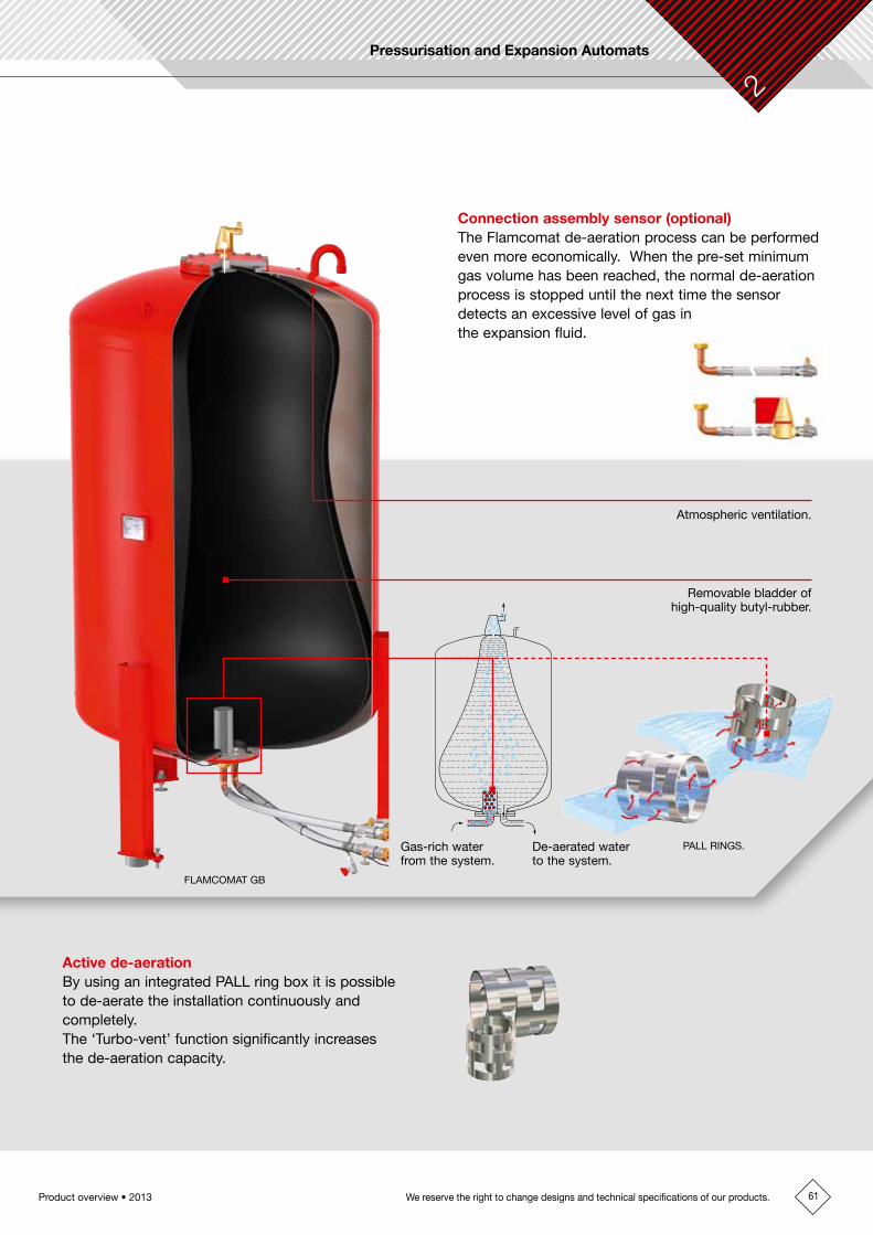
Connection assembly sensor (optional)The Flamcomat de-aeration process can be performed even more economically. When the pre-set minimum gas volume has been reached, the normal de-aeration process is stopped until the next time the sensor detects an excessive level of gas in the expansion fluid.
In this way we can tailor the equipment precisely to the needs of your system.
The Flamcomat is suitable for any size of heating installation and for both refrigeration and air-conditioning installations. The Flamcomat makes sure that the system pressure remains within precise limits and that the system is topped-up automatically should there be any requirements. The venting process is incorporated, dynamic and energy-efficient.
Tomorrow's Technology in Today's Flamcomat
FLAMCOMAT GB
Flexvent Super floatvent with air-intake preventer.
Steel vessel at atmospheric pressure.
Flexible hoses.
Touch pad control panel.
Single or double pump configuration.
Top-up hose.
Lockshield ball valves with drain.
Atmospheric ventilation.
Removable bladder ofhigh-quality butyl-rubber.
Gas-rich water from the system.
De-aerated water to the system.
PALL RINGS.
Active de-aeration By using an integrated PALL ring box it is possible to de-aerate the installation continuously and completely. The ‘Turbo-vent’ function significantly increases the de-aeration capacity.
Benefits of the Flamcomat• The Flamcomat combines pressure-control unit,
dynamic de-aeration and topping-up all in one.• Choice of a range of pump modules.• Proven de-aeration results, as tested independently
by WL / Delft Hydraulics.• Expansion fluid is stored at atmospheric pressure in
a removable butyl-rubber bladder.
61
Pressurisation and Expansion Automats
Product overview • 2013 We reserve the right to change designs and technical specifications of our products.
2
FLAMCOMAT GB
The Flamcomat is a modern, pump-driven pressurisation unit. Thanks to its sophisticated construction we have made it possible to incorporate important functions into one compact unit.
The Flamcomat consists of a pump unit and a pressureless vessel. This modular expansion system can be expanded with additional vessels and accessories from our comprehensive range.
Connection assembly sensor (optional)The Flamcomat de-aeration process can be performed even more economically. When the pre-set minimum gas volume has been reached, the normal de-aeration process is stopped until the next time the sensor detects an excessive level of gas in the expansion fluid.
In this way we can tailor the equipment precisely to the needs of your system.
The Flamcomat is suitable for any size of heating installation and for both refrigeration and air-conditioning installations. The Flamcomat makes sure that the system pressure remains within precise limits and that the system is topped-up automatically should there be any requirements. The venting process is incorporated, dynamic and energy-efficient.
Tomorrow's Technology in Today's Flamcomat
FLAMCOMAT GB
Flexvent Super floatvent with air-intake preventer.
Steel vessel at atmospheric pressure.
Flexible hoses.
Touch pad control panel.
Single or double pump configuration.
Top-up hose.
Lockshield ball valves with drain.
Atmospheric ventilation.
Removable bladder ofhigh-quality butyl-rubber.
Gas-rich water from the system.
De-aerated water to the system.
PALL RINGS.
Active de-aeration By using an integrated PALL ring box it is possible to de-aerate the installation continuously and completely. The ‘Turbo-vent’ function significantly increases the de-aeration capacity.
Benefits of the Flamcomat• The Flamcomat combines pressure-control unit,
dynamic de-aeration and topping-up all in one.• Choice of a range of pump modules.• Proven de-aeration results, as tested independently
by WL / Delft Hydraulics.• Expansion fluid is stored at atmospheric pressure in
a removable butyl-rubber bladder.

62 Product overview • 2013 We reserve the right to change designs and technical specifications of our products.
1. ColdThe automat contains a small amount of water. The automat is still at rest.
5. Topping-upIf the water level in the vessel drops to a critical level, an appropriate amount of water will be carefully pumped into the system from the water mains. This water will be de-aerated (by pressure loss and the PALL rings), before entering the vessel.
70 °C
bar
2
0 3
1
bar
2
31
3. Full powerWhen the system has warmed up completely, the vessel will be almost full to capacity.
2. Warming upThe volume of water and the system pressure increases. The unit responds to this by opening the solenoid valve. Water flows into the pressureless vessel. The water in the vessel is de-aerated due to both the drop in pressure and the presence of the PALL rings.
4. Cooling downThe volume of water and the system pressure decreases. The de-aerated water is pumped from the pressureless vessel back into the system. This restores the system pressure.
How the Automat Works
1) Additional vessel(s) connection must have the same pipeline diameter and vessels must be configured symmetrically. 2) Use if return temperature > 70 °C.
}*** = Shut-off valve, additional accessories or in combination with special model
* = Supplied as standard
** = Accessories
Shut-off valve **
Control unit *
Shut-off valve **
Top-up line for mains water
Basic vessel connection set *
Shut-off valve **
Connection from additional vessel - valve
Connection from additional vessel - pumpVe
ssel
con
nect
ion
**
Bas
ic v
esse
l *
Add
ition
al v
esse
l **
Automatic floatvent with aeration arrestor *
RS485∑ error
APAI
MDB
F/A
M2M1 M1 V2 M3 M/A
E
Min
imum
pre
ssur
e lim
iter
**
Return temperature < 70 °C
Heat source 1 Heat source 2
Supply temperature < 120 °C
Configuration of Flamcomat with double pump, basic and additional vessels and intermediate vessel.
Exp
ansi
on li
ne, d
isch
arge
sid
e
Shu
t-of
f val
ve *
*
Inte
rmed
iate
ves
sel *
* 2)
Exp
ansi
on li
ne, i
nlet
sid
e
Example installation of Flamcomatwith double pump control unit
230V50Hz L N PERS 485 data outputError log sensorTop-upCapacity, analoguePressure, analogueDiaphragm-rupture sensor
Level sensor
}***
BA reflux guard with dirt filter **
Pump discharge line, from expansion vessel to the system.
Pressure sensor.
Solenoid valve.
Safety valve, to protect atmospheric vessel.
Sealable filling/draining valve.
The Flamcomat is a versatile expansion equipment with supreme technical performance. The de-aeration capacity is not dependent on the circulation speed or the pressure in the system. In systems with a large difference between summer and winter operation, we recommend using a double (load-dependant) pumpunit.

63
Pressurisation and Expansion Automats
Product overview • 2013 We reserve the right to change designs and technical specifications of our products.
2
1. ColdThe automat contains a small amount of water. The automat is still at rest.
5. Topping-upIf the water level in the vessel drops to a critical level, an appropriate amount of water will be carefully pumped into the system from the water mains. This water will be de-aerated (by pressure loss and the PALL rings), before entering the vessel.
70 °C
bar
2
0 3
1
bar
2
31
3. Full powerWhen the system has warmed up completely, the vessel will be almost full to capacity.
2. Warming upThe volume of water and the system pressure increases. The unit responds to this by opening the solenoid valve. Water flows into the pressureless vessel. The water in the vessel is de-aerated due to both the drop in pressure and the presence of the PALL rings.
4. Cooling downThe volume of water and the system pressure decreases. The de-aerated water is pumped from the pressureless vessel back into the system. This restores the system pressure.
How the Automat Works
1) Additional vessel(s) connection must have the same pipeline diameter and vessels must be configured symmetrically. 2) Use if return temperature > 70 °C.
}*** = Shut-off valve, additional accessories or in combination with special model
* = Supplied as standard
** = Accessories
Shut-off valve **
Control unit *
Shut-off valve **
Top-up line for mains water
Basic vessel connection set *
Shut-off valve **
Connection from additional vessel - valve
Connection from additional vessel - pumpVe
ssel
con
nect
ion
**
Bas
ic v
esse
l *
Add
ition
al v
esse
l **
Automatic floatvent with aeration arrestor *
RS485∑ error
APAI
MDB
F/A
M2M1 M1 V2 M3 M/A
E
Min
imum
pre
ssur
e lim
iter
**
Return temperature < 70 °C
Heat source 1 Heat source 2
Supply temperature < 120 °C
Configuration of Flamcomat with double pump, basic and additional vessels and intermediate vessel.
Exp
ansi
on li
ne, d
isch
arge
sid
e
Shu
t-of
f val
ve *
*
Inte
rmed
iate
ves
sel *
* 2)
Exp
ansi
on li
ne, i
nlet
sid
e
Example installation of Flamcomatwith double pump control unit
230V50Hz L N PERS 485 data outputError log sensorTop-upCapacity, analoguePressure, analogueDiaphragm-rupture sensor
Level sensor
}***
BA reflux guard with dirt filter **
Pump discharge line, from expansion vessel to the system.
Pressure sensor.
Solenoid valve.
Safety valve, to protect atmospheric vessel.
Sealable filling/draining valve.
The Flamcomat is a versatile expansion equipment with supreme technical performance. The de-aeration capacity is not dependent on the circulation speed or the pressure in the system. In systems with a large difference between summer and winter operation, we recommend using a double (load-dependant) pumpunit.

64 Product overview • 2013 We reserve the right to change designs and technical specifications of our products.
FLAMCOMAT - PUMP UNITS
For heating and chilled water (cooling) installations.
Flamcomats with pump units are used for storage of expansion water, de-aeration and topping up your installation automatically as an integrated controlled unit carried out with state of the art micro-electronics.
• The easy to use, detachable control unit shows all system operation and fault conditions clearly and conveniently. The control unit can also be used remotely, up to a distance of 500 metres, so that you can view the system from your workstation and may be interfaced with external systems to give a networked control and alarm system.
•By using Flamco-patented PALL-rings, gas bubbles down to a size of 18 microns can be removed from the system. The PALL-rings have a large adhesive surface, which means that the Flamcomat can eliminate large and small air bubbles from your system. This is described further in the independent research report commissioned from the Technical University of Delft, the Netherlands, which can be obtained from Flamco.
•State-of-the-art technology gives low power usage, long life and ease of maintenance.•Red (RAL 3002) epoxy powder coating.•Maximum temperature on bladder (EN 13831/8): 70 °C.•Maximum temperature at (heating) outlet: 120 °C.
Single Pump Control (PN 10)
Type* Pump orientation
Maximumworkingpressure
[bar]
DimensionsL. x W. x H.
[mm]
Connection (F) to Weight[kg]
OrderCode
Tank System Watersupply
MM (PN 6) hor. 3.0 660 x 420 x 330 G 1" Rp 3/4" Rp 1/2" 12 1 17880M 0 hor. 3.5 840 x 530 x 540 G 1 1/4" G 1 1/4" Rp 1/2" 35 1 17786M 01 hor. 3.5 840 x 530 x 540 G 1 1/4" G 1 1/4" Rp 1/2" 35 1 17787M 02 hor. 3.5 840 x 530 x 540 G 1 1/4" G 1 1/4" Rp 1/2" 35 1 17789M 10 hor. 5.0 840 x 530 x 540 G 1 1/4" G 1 1/4" Rp 1/2" 40 1 17780M 20 hor. 5.0 840 x 530 x 540 G 1 1/4" G 1 1/4" Rp 1/2" 40 1 17781M 60 vert. 8.5 842 x 610 x 535 G 1 1/2" G 1 1/2" Rp 1/2" 60 1 17784
* For larger, more powerful systems please contact Flamco.
Single Pump Control (PN 16)
Type* Pump orientation
Maximumworkingpressure
[bar]
DimensionsL. x W. x H.
[mm]
Connection (F) to Weight[kg]
OrderCode
Tank System Watersupply
M 80 vert. 10.2 878 x 610 x 595 G 1 1/2" G 1 1/2" Rp 1/2" 70 1 17882M 100 vert. 14.1 1030 x 610 x 595 G 1 1/2" G 1 1/2" Rp 1/2" 75 1 17884M 130 vert. 14.4 1190 x 610 x 595 G 1 1/2" G 1 1/2" Rp 1/2" 85 1 17886
* For larger, more powerful systems please contact Flamco.

65
Pressurisation and Expansion Automats
Product overview • 2013 We reserve the right to change designs and technical specifications of our products.
2
Double Pump Control (PN 10)
Type* Pump orientation
Maximumworkingpressure
[bar]
DimensionsL. x W. x H.
[mm]
Connection (F) to Weight[kg]
OrderCode
Tank System Watersupply
DM hor. 3.0 660 x 385 x 340 G 1" Rp 3/4" Rp 1/2" 14 1 17881D 02 hor. 3.5 840 x 900 x 670 G 1 1/2" G 1 1/2" Rp 1/2" 65 1 17788D 10 hor. 5.0 840 x 900 x 670 G 1 1/2" G 1 1/2" Rp 1/2" 75 1 17782D 20 hor. 5.0 840 x 900 x 670 G 1 1/2" G 1 1/2" Rp 1/2" 75 1 17783D 60 vert. 8.5 842 x 850 x 580 G 1 1/2" G 1 1/2" Rp 1/2" 116 1 17785
* For larger, more powerful systems please contact Flamco.
Double Pump Control (PN 16)
Type* Pump orientation
Maximumworkingpressure
[bar]
DimensionsL. x W. x H.
[mm]
Connection (F) to Weight[kg]
OrderCode
Tank System Watersupply
D 80 vert. 10.2 878 x 910 x 580 G 1 1/2" G 1 1/2" Rp 1/2" 140 1 17883D 100 vert. 14.1 1030 x 910 x 580 G 1 1/2" G 1 1/2" Rp 1/2" 144 1 17885D 130 vert. 14.4 1190 x 910 x 580 G 1 1/2" G 1 1/2" Rp 1/2" 162 1 17887
* For larger, more powerful systems please contact Flamco.

66 Product overview • 2013 We reserve the right to change designs and technical specifications of our products.
FLAMCOMAT VESSELS
For heating and chilled water (cooling) installations.
A multi function product which provides all the essential requirements for a sealed chilled or heated water system i.e. automatic expansion control, pressurisation, de-aeration and make-up.
•Pressureless vessel without automat.•Replaceable bladder.•Automatically maintains volumetric control during heating or cooling cycles along with automatic make-up.• Total air removal, even when the system is in a state of equilibrium, unique turbo de-aeration facility provides continuous de-
aeration when required.• Low pressure de-aeration using the patented PALL-ring coalescence process which leads to a long life cycle and improved efficiency.
•Maximum working pressure (design): 3.0 bar.•Maximum temperature on bladder (EN 13831/8): 70 °C.• In accordance with European Pressure Equipment Directive 97/23/EC.
Flamcomat GB Main Vessels
Type Capa-city[l]
Dimensions Syst.conn.
(M)
Weight[kg]
OrderCode
Ø[mm]
H.[mm]
GB 150 150 550 1350 G 1 1/2" 56 1 17710GB 200 200 550 1530 G 1 1/2" 71 1 17711GB 300 300 550 2030 G 1 1/2" 91 1 17712GB 400 400 750 1535 G 1 1/2" 131 1 17713GB 500 500 750 1760 G 1 1/2" 151 1 17729GB 600 600 750 1955 G 1 1/2" 161 1 17714GB 800 800 750 2355 G 1 1/2" 196 1 17715GB 1000 1000 1000 1915 G 1 1/2" 261 1 17726GB 1000 1000 750 2855 G 1 1/2" 227 1 17716GB 1200 1200 1000 2210 G 1 1/2" 291 1 17717GB 1600 1600 1000 2710 G 1 1/2" 346 1 17718GB 2000 2000 1200 2440 G 1 1/2" 431 1 17719GB 2800 2800 1200 3040 G 1 1/2" 516 1 17720GB 3500 3500 1200 3840 G 1 1/2" 626 1 17721GB 5000 5000 1500 3570 G 1 1/2" 1241 1 17722GB 6500 6500 1800 3500 G 1 1/2" 1711 1 17723GB 8000 8000 1900 3650 G 1 1/2" 1831 1 17724GB 10000 10000 2000 4050 G 1 1/2" 2026 1 17725
Flamcomat BB Auxiliary Vessels
Type Capa-city[l]
Dimensions Syst.conn.
(M)
Weight[kg]
OrderCode
Ø[mm]
H.[mm]
BB 150 150 550 1350 G 1 1/2" 55 1 17760BB 200 200 550 1530 G 1 1/2" 70 1 17761BB 300 300 550 2030 G 1 1/2" 90 1 17762BB 400 400 750 1535 G 1 1/2" 130 1 17763BB 500 500 750 1760 G 1 1/2" 150 1 17779BB 600 600 750 1955 G 1 1/2" 160 1 17764BB 800 800 750 2355 G 1 1/2" 195 1 17765BB 1000 1000 750 2855 G 1 1/2" 226 1 17766BB 1000 1000 1000 1915 G 1 1/2" 260 1 17776BB 1200 1200 1000 2210 G 1 1/2" 290 1 17767BB 1600 1600 1000 2710 G 1 1/2" 345 1 17768BB 2000 2000 1200 2440 G 1 1/2" 430 1 17769BB 2800 2800 1200 3040 G 1 1/2" 515 1 17770BB 3500 3500 1200 3840 G 1 1/2" 625 1 17771BB 5000 5000 1500 3670 G 1 1/2" 1240 1 17772BB 6500 6500 1800 3500 G 1 1/2" 1710 1 17773BB 8000 8000 1900 3650 G 1 1/2" 1830 1 17774BB 10000 10000 2000 4050 G 1 1/2" 2025 1 17775

67
Pressurisation and Expansion Automats
Product overview • 2013 We reserve the right to change designs and technical specifications of our products.
2
ACCESSORIES FOR AUTOMATS
Drain and Refill Sets
Type OrderCode
Drain set with pulse water meter small - 16 m3/h 1 17650Drain set with pulse water meter large - 20 m3/h 1 17651Drain set with water meter small - 16 m3/h 1 17652Drain set with water meter large - 20 m3/h 1 17653
Standard refill system with pulse hot water meter - 50 Hz / 60 Hz 1 17654
Steel Cabinet
Type OrderCode
Steel cabinet for mono pump horizontal (M 0 - M 20) 1 17655Steel cabinet for mono pump vertical (M 60 - M 130) 1 17656Steel cabinet for dual pump horizontal (D 0 - D 20) 1 17657Steel cabinet for dual pump vertical (D 60 - D 130) 1 17658
Bimetallic Temperature Switch
Type OrderCode
Bimetallic Temperature Switch 1 17659
Soft Foam Heat Insulation
For Flamcomat vessels.
For type: OrderCode
Flamcomat 150 1 17744Flamcomat 200 1 17745Flamcomat 300 1 17746Flamcomat 400 1 17747Flamcomat 600 1 17748Flamcomat 800 1 17749Flamcomat 1000 1 17750Flamcomat 1200 1 17751Flamcomat 1600 1 17752Flamcomat 2000 1 17753

68 Product overview • 2013 We reserve the right to change designs and technical specifications of our products.
Ball Valve
With drain connection.
Rp R
G
Type Connection For pump set OrderCode
Rp G R Drain
Valve DN 20 3/4" 1" 3/4" G 3/4" MM, DM 1 17734Valve DN 25 1" 1 1/4" 1" G 3/4" M 01, M 10, M 20 1 17737Valve DN 32 1 1/4" 1 1/2" 1 1/4" G 3/4" D 02, D 10, D 20, M 60, D 60 1 17738Ball valve with draining DN 25 without adapter PN 16 - 120 °C
1" 1 1/4" - 3/4" MM, M 01, M 10, M 20 2 17660
Flamcomat valve caps DN 32 without adapter PN 16 - 120 °C
1 1/4" 1 1/2" - 3/4" D 02, D 10, D 20, M 60, D 60 2 17661
Flexible Connecting Kit
For connecting the Flamcomat main or auxiliary vessel to the pump-unit, face sealed female, with ball valve and drainage valve.
Type Suitable for Connection OrderCode
Pump-unit Vessel sizes[l]
Vessel Pump-unit
Flexible connection 1 MM, DM 150 - 1600 G 1 1/2" G 1" 1 17841Flexible connection 2 MM, DM 2000 - 10000 G 1 1/2" G 1" 1 17842Flexible connection 3 MM - M 20 150 - 1600 G 1 1/2" G 1 1/4" 1 17741Flexible connection 4 MM - M 20 2000 - 10000 G 1 1/2" G 1 1/4" 1 17742Flexible connection 5 M 60, D 02-60 150 - 1600 G 1 1/2" G 1 1/2" 1 17755Flexible connection 6 M 60, D 02-60 2000 - 5000 G 1 1/2" G 1 1/2" 1 17756Flexible connection 7 M 60, D 02-60 6500 - 10000 G 1 1/2" G 1 1/2" 1 17757
Gas Sensor Connecting Group
For connecting the Flamcomat main vessel to the pump unit, face sealed female, with ball valve anddrainage valve. Includes a de-aeration sensor for signalling the control unit to continue or stop active de-aeration.
Type Optional for Connection to OrderCode
Pump-unit Vessel sizes[l]
Vessel Pump-unit
Sensor connecting group 1 MM, DM 150 - 1600 1 1/2" 1" 1 17810Sensor connecting group 2 MM, DM 2000 - 10000 1 1/2" 1" 1 17811Sensor connecting group 3 M 01 - M 20 150 - 1600 1 1/2" 1 1/4" 1 17812Sensor connecting group 4 M 01 - M 20 2000 - 10000 1 1/2" 1 1/4" 1 17813Sensor connecting group 5 M 60, D 02-60 150 - 1600 1 1/2" 1 1/2" 1 17814Sensor connecting group 6 M 60, D 02-60 2000 - 5000 1 1/2" 1 1/2" 1 17815Sensor connecting group 7 M 60, D 02-60 6500 - 10000 1 1/2" 1 1/2" 1 17816

69
Pressurisation and Expansion Automats
Product overview • 2013 We reserve the right to change designs and technical specifications of our products.
2
Backflow Security
Including strainer and shut-off valves.With multiple potable water approvals.
Type Connection(F - M)
Weight[kg]
OrderCode
Backflow security 1/2" - 1/2" 0.6 1 17736
Surge Vessel (PN 6)
Type Capacity[l]
Dimensions Syst.conn.
Weight[kg]
OrderCode
Ø[mm]
H.[mm]
Surge vessel type M 18 286 600 1/2" 8.5 1 17732Surge vessel type D 18 286 600 1 1/4" 10 1 17733
Impulse Output Water Meter
Type Features OrderCode
Impulse output water meter 1 impulse/10 litres 1 17739
Rotating Connection, Face Sealed
Type Connection to Weight[kg]
OrderCode
Vessel(F)
Control unit(M)
Vessel connection type 3 1 1/2" 3/4" 0.4 1 17754Vessel connection type 4 1 1/2" 1" 0.4 1 17730Vessel connection type 5 1 1/2" 1 1/4" 0.5 1 17731
OPTIONAL CONTROL UNITS
Easycontact
Remote volt free failure contacts for pressure, level and thermal motor protection.
Type Control unit Optional for OrderCode
F SCU SPC M-K/S M-K/C M-K/U Flam-comat
Easycontact 4 4 4 4 4 4 4 1 23649
Diaphragm Rupture Sensor
Remote monitoring.Cannot be integrated at a later date.
Type External/Internal
Control unit Optional for OrderCode
S SPC M-K/S M-K/U Flam-comat
Diaphragm rupture sensor External 4 4 4 4 - 1 22386
Soft Starter for Pumps
Internal. Reduces the dynamic pressure at pump starts.
Type Control unit Optional for OrderCode
F SPC M-K/U Flamcomat
Soft starter for M 80 - M 130 - 4 - 4 1 17662Soft starter for D 80 - D 130 - 4 - 4 1 17663

70 Product overview • 2013 We reserve the right to change designs and technical specifications of our products.
FLEXCON MPR-S - PUMP UNITS
For expansion water control and topping up of heating and chilled water (cooling) installations.•Expansion water can be stored and topped up in your installation automatically, as an integrated unit controlled and carried
out with state of the art electronics.• The control unit is the proven "Steuerautomat" with convenient methods of programming.
23
22
21
20
19
18
17
16
15
14
13
12
11
10
9
8
7
6
5
4
3
2
1
0
1.5;2.5
1.4;2.4
1.7;2.7
1.6;2.62.7
2.6
1.3;2.3
1.2;2.2
2.5
2.4
2.3
2.2
0 1 2 3 4 5 6 7
PN16
Boiler heating power (MW) Single changeover operation Parallel operation
PN25
Heating power rating (MW) Single changeover operation Parallel operation
Boiler output [MW] / cooling capacity [MW] = boiler output x 2.42
Sys
tem
pre
ssur
e (b
ar)
MPRS pump sets operating range
MPR-S Single Pump Unit
Suitable for boiler heating power range: 0.9 - 3.2 MW.
Type Pressure range[bar]
DimensionsL. x W. x H.
[mm]
Weight[kg]
OrderCode
MPR-S / 1.2 PN 16 2.0 - 4.1 1716 x 1015 x 700 113 1 19741MPR-S / 1.3 PN 16 3.2 - 5.9 1716 x 1015 x 700 115 1 19743MPR-S / 1.4 PN 16 4.9 - 9.6 1716 x 1015 x 700 120 1 19744MPR-S / 1.5 PN 16 6.8 - 13.3 1716 x 1015 x 700 124 1 19760MPR-S / 1.6 PN 25 10.5 - 18.1 1716 x 1015 x 700 130 1 19770MPR-S / 1.7 PN 25 13.2 - 22.0 1716 x 1015 x 700 140 1 19771
MPR-S Double Pump Unit
Suitable for boiler heating power range: 0.9 - 6.1 MW.
Type Pressure range[bar]
DimensionsL. x W. x H.
[mm]
Weight[kg]
OrderCode
MPR-S / 2.2 PN 16 2.0 - 4.1 1716 x 1015 x 700 139 1 19750MPR-S / 2.3 PN 16 3.2 - 5.9 1716 x 1015 x 700 143 1 19751MPR-S / 2.4 PN 16 4.9 - 9.6 1716 x 1015 x 700 153 1 19752MPR-S / 2.5 PN 16 6.8 - 13.3 1716 x 1015 x 700 161 1 19765MPR-S / 2.6 PN 25 10.5 - 18.1 1716 x 1015 x 700 173 1 19775MPR-S / 2.7 PN 25 13.2 - 22.0 1716 x 1015 x 700 193 1 19776
Analogue Signal Output
• Internal.• For analogue signalling (0-10 V) of vessel volume (0-100 %) and system pressure (0-16 bar).•Build-in afterwards is possible.•Setting up data processing and visualisation is left up to the contractor.
Type Control unit Optional for OrderCode
F SPC M-K/U Flamcomat
Analogue signal output - 4 4 4 1 17802
Bus Coupler LONWorks Standard
External. Interface converter from RS485 SDS to LONWorks for visualisation in LON networks and LON building services control systems.
Type Control unit Optional for OrderCode
F SCU SPC M-K/U M-K/C Flam-comat
Bus Coupler LONWorks standard - Module 40
- 4 4 4 4 4 1 17795
SD Card Module
External. Forsavingparameterfiles.SD Card module used for:• SavingofSPCparameterfiles.• DownloadingoffilesviaSDCardtoPC.• TransmissionofthefilestoServicecentre.• Uploadingoffilesadaptedbytheservicesupport.
Type Control unit Optional for OrderCode
F SPC M-K/U Flamcomat
SD card module - 4 4 4 1 17803

71
Pressurisation and Expansion Automats
Product overview • 2013 We reserve the right to change designs and technical specifications of our products.
2
FLEXCON MPR-S - PUMP UNITS
For expansion water control and topping up of heating and chilled water (cooling) installations.•Expansion water can be stored and topped up in your installation automatically, as an integrated unit controlled and carried
out with state of the art electronics.• The control unit is the proven "Steuerautomat" with convenient methods of programming.
23
22
21
20
19
18
17
16
15
14
13
12
11
10
9
8
7
6
5
4
3
2
1
0
1.5;2.5
1.4;2.4
1.7;2.7
1.6;2.62.7
2.6
1.3;2.3
1.2;2.2
2.5
2.4
2.3
2.2
0 1 2 3 4 5 6 7
PN16
Boiler heating power (MW) Single changeover operation Parallel operation
PN25
Heating power rating (MW) Single changeover operation Parallel operation
Boiler output [MW] / cooling capacity [MW] = boiler output x 2.42
Sys
tem
pre
ssur
e (b
ar)
MPRS pump sets operating range
MPR-S Single Pump Unit
Suitable for boiler heating power range: 0.9 - 3.2 MW.
Type Pressure range[bar]
DimensionsL. x W. x H.
[mm]
Weight[kg]
OrderCode
MPR-S / 1.2 PN 16 2.0 - 4.1 1716 x 1015 x 700 113 1 19741MPR-S / 1.3 PN 16 3.2 - 5.9 1716 x 1015 x 700 115 1 19743MPR-S / 1.4 PN 16 4.9 - 9.6 1716 x 1015 x 700 120 1 19744MPR-S / 1.5 PN 16 6.8 - 13.3 1716 x 1015 x 700 124 1 19760MPR-S / 1.6 PN 25 10.5 - 18.1 1716 x 1015 x 700 130 1 19770MPR-S / 1.7 PN 25 13.2 - 22.0 1716 x 1015 x 700 140 1 19771
MPR-S Double Pump Unit
Suitable for boiler heating power range: 0.9 - 6.1 MW.
Type Pressure range[bar]
DimensionsL. x W. x H.
[mm]
Weight[kg]
OrderCode
MPR-S / 2.2 PN 16 2.0 - 4.1 1716 x 1015 x 700 139 1 19750MPR-S / 2.3 PN 16 3.2 - 5.9 1716 x 1015 x 700 143 1 19751MPR-S / 2.4 PN 16 4.9 - 9.6 1716 x 1015 x 700 153 1 19752MPR-S / 2.5 PN 16 6.8 - 13.3 1716 x 1015 x 700 161 1 19765MPR-S / 2.6 PN 25 10.5 - 18.1 1716 x 1015 x 700 173 1 19775MPR-S / 2.7 PN 25 13.2 - 22.0 1716 x 1015 x 700 193 1 19776

72 Product overview • 2013 We reserve the right to change designs and technical specifications of our products.
FLEXCON M-P
Pump controlled, pressureless vessels with replaceable butyl rubber bladder for high pressures.
Special microprocessor controlled automatic systems for water expansion management, pressure maintenance and controlled top-up/pressurisation of hydronic cooling and heating installations with high pressure ratings or large heating/cooling outputs.
The system comprises of one or more expansion vessels, a single or dual pump unit, a microprocessor controller and the appropriate sensors, valves and connection hardware.
•Red (RAL 3002) epoxy powder coating.•Maximum working pressure (design): 3.0 bar.•Maximum temperature (EN 13831/8): 70 °C.•Maximum temperature at (heating) outlet: 120 °C.• In accordance with EN 13831/8. • Factory tested to PED97/23/EC standard.•Material quality:- ASTM/ISO: A181 class 60 / S235JRG2. - EN/ISO: P245N.
Flexcon M-P/G Main Vessels
First vessel in combination with MPRS pump unit. Includes weight sensor and flexibleconnection2".
•Nominal pressure ratings: PN10, 16 and 25.•Maximum boiler output: 7 MW.•Maximum chiller output: 17 MW.• Larger volumes 6,500 - 10,000 litres available on request.
Type Capacity[l]
Dimensions Weight[kg]
OrderCode
Ø[mm]
H.[mm]
Flexcon M-P/G 400 400 750 1535 131 1 22181Flexcon M-P/G 600 600 750 1955 161 1 22182Flexcon M-P/G 800 800 750 2355 196 1 22183Flexcon M-P/G 1000 1000 750 2855 227 1 22184Flexcon M-P/G 1200 1200 1000 2210 291 1 22186Flexcon M-P/G 1600 1600 1000 2710 346 1 22187Flexcon M-P/G 2000 2000 1200 2440 431 1 22188Flexcon M-P/G 3500 3500 1200 3840 626 1 22190Flexcon M-P/G 5200 5200 1500 3570 1241 1 22191
Flexcon M-P/B Auxiliary Vessels
As M-P/G but without a weight sensor.
Type Capacity[l]
Dimensions Weight[kg]
OrderCode
Ø[mm]
H.[mm]
Flexcon M-P/B 200 200 550 1530 71 1 22301Flexcon M-P/B 400 400 750 1535 131 1 22302Flexcon M-P/B 600 600 750 1955 161 1 22303Flexcon M-P/B 800 800 750 2355 196 1 22304Flexcon M-P/B 1000 1000 750 2855 227 1 22305Flexcon M-P/B 1200 1200 1000 2210 291 1 22306Flexcon M-P/B 1600 1600 1000 2710 346 1 22307Flexcon M-P/B 2000 2000 1200 2440 431 1 22308Flexcon M-P/B 2800 2800 1200 3040 516 1 22309Flexcon M-P/B 3500 3500 1200 3840 626 1 22310Flexcon M-P/B 5200 5200 1500 3570 1241 1 22311

73
Pressurisation and Expansion Automats
Product overview • 2013 We reserve the right to change designs and technical specifications of our products.
2
FLEXCON M-P 10-60
M-P 10-60 pump controlled, custom designed expansion automats for boiler power ratings between 10 and 60 MW.
Especially for district heating or cooling systems it is important to have a maximum reliability and adaptation to the system parameters.The M-P 10-60 basic design permits us to supply exactly to customers needs.
•Maximum boiler capacity: 60 MW.•Maximum chiller capacity: 140 MW.• Larger systems available on request.
ACCESSORIES FOR FILLING
For heating and chilled water (cooling) installations.
Twin outlet option available.
NFE 1.1 / NFE 1.2
NFE 2.1 / NFE 2.2
NFE 3
MVE 1
MVE 2G ¾
G ¾
G ¾
G ¾
G ¾
Rp ½
Rp ½Rp ½
Rp ½Rp ½
MVE 1 Direct Pressurisation Control
Automatic topping-up direct from water mains expansion automats (signal controlled) or self supported with pressure sensor.
•With digital control, pressure sensor and ball valve.•Maximum operating pressure: 10.0 bar.•Maximum working temperature: 90 °C.
Type L.[mm]
Connection to Weight[kg]
OrderCode
Potable water
System
MVE 1 300 G 3/4" Rp 1/2" 9 1 23785

74 Product overview • 2013 We reserve the right to change designs and technical specifications of our products.
Digital pressurisation equipment including:
• Bright LED display incorporating scrolling messages showing status and alarm modes.
• Single or twin pump configurations.• Complete with integral water break tank utilising an
AB airgap and a WRAS approved float valve.• Twin pump equipment operates as cyclic duty -
standby with automatic changeover.• Internal alarm with mute function.• Security password protected.• Auto resetting low water detection, for pump protection.• Auto resetting high and low pressure alarm.• Digital pressure setpoint with adjustable differential.• Flood protection provided by pump run time limiter.• Normally closed, common fault, volt free contact
(Boiler interlock).• Normally open, individual volt free contacts for pump
trip, high pressure, low pressure and sensor health.• All volt free contacts are for use with electrical
supplies up to 240V with a maximum current draw of 5 amps.
• RS 485 Connectivity.• Hours run counter (per pump).• 12 month service reminder.• Excessive start alarm (>3 times in 8 hours).• Pump pulse option (2 second pulse per pump if
inactive for 60 days).• Fill system option (Not available on 130D/230D).
Flexconpak (cabinet housed) and Basepak (baseplate mounted) packaged sealed system units, Presspak packaged sealed system units and floor standing pressurisation units are available with a range of options to suit your specific requirements.For full details please contact our Sales Office.
Selection Guide for Digital Pressurisation Units
Deliv
ery
pres
sure
[bar
(g)]
Flow rate [l/min] Flow rate [l/min]
Deliv
ery
pres
sure
[bar
(g)]
Flow rate [l/min]
Deliv
ery
pres
sure
[bar
(g)]
Flow rate [l/min]
Deliv
ery
pres
sure
[bar
(g)]
Flow rate [l/min]
Deliv
ery
pres
sure
[bar
(g)]
Flow rate [l/min]
Deliv
ery
pres
sure
[bar
(g)]
For large or tall sealed heated or chilled water systems traditional expansion vessels are not always the most effi cient solution in terms of operational pressure or physical footprint. Flamco expansion systems balance the system pressure, using a highly effi cient vessel design and control equipment.
We produce a comprehensive range of models that offer high-quality performance and versatility which may be further enhanced by the addition of numerous optional accessories. Flamco has an adaptable, modular range to suit every requirement.
Flamco Digital Pressurisation Units
Mini 130D / 230D Midi 125D / 225D Midi 150D / 250D
Flexfi ller 125D / 225D Flexfi ller 150D / 250D Flexfi ller 280DS
MVE 2 Solenoid Valve Unit
Solenoid valve units for systems with expansion automats with SDS control units.
•With ball valve.•Maximum operating pressure: 10.0 bar.•Maximum working temperature: 90 °C.
Type L.[mm]
Connection to Weight[kg]
OrderCode
Potable water
System
MVE 2 175 G 3/4" Rp 1/2" 2 1 23786
NFE 1 Top-up Unit
Used for direct top up from potable water supply. • Consistsofwatermeter,dirtcollector,backflowpreventiondeviceandballvalve.
Type L.[mm]
Connection to Weight[kg]
OrderCode
Potable water
System
NFE 1.1 355 Rp 1/2" G 3/4" 3 1 23780NFE 1.2* 355 Rp 1/2" G 3/4" 3 1 23781
* NFE 1.2 has an impulse output water meter (10 litres / impulse).
NFE 2 Top-up Unit
Usedfortopupfromawatersupply,whereabackflowpreventiondeviceisnotneeded.• Consists of water meter, dirt collector, ball valve and non-return valve.
Type L.[mm]
Connection to Weight[kg]
OrderCode
Potable water
System
NFE 2.1 200 Rp 1/2" G 3/4" 2 1 23782NFE 2.2* 200 Rp 1/2" G 3/4" 2 1 23783
* NFE 2.2 has an impulse output water meter (10 litres / impulse).
NFE 3 Ball Valve With Dirt Collector
Usedfortopupfromawatersupply,whereabackflowpreventiondeviceisnotneeded.• Consists of dirt collector, ball valve and non-return valve.
Type L.[mm]
Connection to Weight[kg]
OrderCode
Potable water
System
NFE 3* 130 Rp 1/2" G 3/4" 0.5 1 23784
* NFE 3 is not necessary if the top-up water is free from impurities > 0.2 mm, the system has not been filled from a district-heating system and sufficient filters have been fitted for the solenoid valve (MVE).
Flamco-Fill PE Top-up Unit (pressurisation)
The Flamco-Fill PE pressurisation units monitor the pressure in sealed heating and cooling installations and tops them up as necessary. Topping-up depends on the pressure or level at a pre-set interval. There are two working methods available. One for installations with expansion automats (command based on level in automat) and one for installations with Flexcon expansion vessels (command based on installation pressure).
•All models have an impulse water meter for monitoring the amount of water topped up.•Any malfunctions will result in a visible alarm and may be made visible automatically in the
malfunction log, even via remote control (dead socket).
Type Dimensions Connection to Weight[kg]
OrderCode
L.[mm]
D.[mm]
H.[mm]
Potable water
System
Flamco-Fill PE 400 320 495 1/2 1/2 25 1 23757

75
Pressurisation and Expansion Automats
Product overview • 2013 We reserve the right to change designs and technical specifications of our products.
2
Digital pressurisation equipment including:
• Bright LED display incorporating scrolling messages showing status and alarm modes.
• Single or twin pump configurations.• Complete with integral water break tank utilising an
AB airgap and a WRAS approved float valve.• Twin pump equipment operates as cyclic duty -
standby with automatic changeover.• Internal alarm with mute function.• Security password protected.• Auto resetting low water detection, for pump protection.• Auto resetting high and low pressure alarm.• Digital pressure setpoint with adjustable differential.• Flood protection provided by pump run time limiter.• Normally closed, common fault, volt free contact
(Boiler interlock).• Normally open, individual volt free contacts for pump
trip, high pressure, low pressure and sensor health.• All volt free contacts are for use with electrical
supplies up to 240V with a maximum current draw of 5 amps.
• RS 485 Connectivity.• Hours run counter (per pump).• 12 month service reminder.• Excessive start alarm (>3 times in 8 hours).• Pump pulse option (2 second pulse per pump if
inactive for 60 days).• Fill system option (Not available on 130D/230D).
Flexconpak (cabinet housed) and Basepak (baseplate mounted) packaged sealed system units, Presspak packaged sealed system units and floor standing pressurisation units are available with a range of options to suit your specific requirements.For full details please contact our Sales Office.
Selection Guide for Digital Pressurisation Units
Deliv
ery
pres
sure
[bar
(g)]
Flow rate [l/min] Flow rate [l/min]
Deliv
ery
pres
sure
[bar
(g)]
Flow rate [l/min]
Deliv
ery
pres
sure
[bar
(g)]
Flow rate [l/min]
Deliv
ery
pres
sure
[bar
(g)]
Flow rate [l/min]
Deliv
ery
pres
sure
[bar
(g)]
Flow rate [l/min]
Deliv
ery
pres
sure
[bar
(g)]
For large or tall sealed heated or chilled water systems traditional expansion vessels are not always the most effi cient solution in terms of operational pressure or physical footprint. Flamco expansion systems balance the system pressure, using a highly effi cient vessel design and control equipment.
We produce a comprehensive range of models that offer high-quality performance and versatility which may be further enhanced by the addition of numerous optional accessories. Flamco has an adaptable, modular range to suit every requirement.
Flamco Digital Pressurisation Units
Mini 130D / 230D Midi 125D / 225D Midi 150D / 250D
Flexfi ller 125D / 225D Flexfi ller 150D / 250D Flexfi ller 280DS

76 Product overview • 2013 We reserve the right to change designs and technical specifications of our products.
Flexfiller Selection Guide
HL switch kits available on request.Mechanical Presspaks available on request.
Ref Description Automaticpump
change-over
Nr. ofpumps
Top upflow rate
(po. max.)[ l/min.]
Maximumoutput
pressure[bar(g)]
Minimumoutput
pressure[bar(g)]
Full loadcurrent
[A]
DigitalHigh / Lowswitches
Digital system
diagnostic
130D Mini digitalpressurisation unit
- 1 0.4 3.0 0.5 3.0 4 4
230D Twin pump mini digitalpressurisation unit
4 2 0.4 3.0 0.5 3.0 4 4
125D Digital 25m headpressurisation unit
- 1 10.0 2.5 0.5 5.0 4 4
150D Digital 50m headpressurisation unit
- 1 6.5 5.0 1.0 5.0 4 4
225D Twin pump digital 25m head pressurisation unit
4 2 10.0 2.5 1.0 3.2 4 4
250D Twin pump digital 50m head pressurisation unit
4 2 6.5 5.0 1.0 3.2 4 4
280D Twin pump digital 80mhead pressurisation unit
4 2 30.0 8.0 1.0 6.7 4 4
Flexfiller Mini
Mini Pressurisation Unit for use on heating systems utilising a 300 litre expansion vessel or less, or chilled systems utilising a 50 litre expansion vessel or less.
•Electric pump, 220-240V 50Hz 1ph (110V 60Hz 1ph available upon request).
Type Pump Qty
Dimensions Syst.conn.BSP (M)
Dryweight
[kg]
OrderCode
W.[mm]
D.[mm]
H.[mm]
Flexfiller Mini 130 D 1 245 155 485 1/4" 6 1 17455Flexfiller Mini 230 D 2 245 155 485 1/4" 6.2 1 17456
Flexfiller Midi
Wall mounted pressurisation unit.
•Electric pump, 220-240V 50Hz 1ph (110V 60Hz 1ph available upon request).
Type Pump Qty
Dimensions Syst.conn.BSP (F)
Dryweight
[kg]
OrderCode
W. [mm]
D. [mm]
H.[mm]
Flexfiller Midi 125 D 1 245 245 485 1/2" 13.5 1 17460Flexfiller Midi 150 D 1 360 276 485 1/2" 14 1 17461Flexfiller Midi 225 D 2 360 276 485 1/2" 16 1 17462Flexfiller Midi 250 D 2 360 276 485 1/2" 16 1 17463
Flexfiller Standard
Free standing pressurisation unit.
•Electric pump, 220-240V 50Hz 1ph (110V 60Hz 1ph available upon request).
Type Pump Qty
Dimensions Syst.conn.BSP (M)
Dryweight
[kg]
OrderCode
W.[mm]
D.[mm]
H.[mm]
Flexfiller 125 D 1 470 320 800 1/2" 28 1 17395Flexfiller 150 D 1 470 320 800 1/2" 28 1 17396Flexfiller 225 D 2 470 320 800 1/2" 30 1 17397Flexfiller 250 D 2 470 320 800 1/2" 40 1 17398Flexfiller 280 DS 2 470 230 800 1/2" 42 1 17394Flexfiller 2100 D 2 680 730 1590 1/2" 170 1 17393

77
Pressurisation and Expansion Automats
Product overview • 2013 We reserve the right to change designs and technical specifications of our products.
2
Flexfiller Twin System
Compact, totally enclosed units with user-friendly microprocessor for use with Flexcon expansion vessels in order to maintain a minimum system pressure. The controller provides low and high pressure monitoring as well as system diagnostic tools.
•Electric pump, 220-240V 50Hz 1ph (110V 60Hz 1ph available upon request).
Type Pump Qty
Dimensions Syst.conn.BSP (M)
Dryweight
[kg]
OrderCode
W.[mm]
D.[mm]
H.[mm]
Twinsystem 2 x 125 D 2 * 470 320 800 1/2" 35 1 17464Twinsystem 2 x 150 D 2 * 470 320 800 1/2" 40 1 17465Twinsystem 2 x 180 DS 2 * 470 230 800 1/2" 42 1 17466
* 1 pump for each system.
Flexfiller Digital Glycol Pressurisation Unit
Compact, totally enclosed unit with user-friendly microprocessor for use with Flexcon expansion vessels in order to maintain a minimum system pressure. The controller provides low and high pressure monitoring as well as system diagnostic tools. Glycol is introduced on demand from a dedicated Glycol storage tank.
• Systemquick-fillmode.•Manual mix options set on site up to 50%.•Password protection for parameter entry.•Electric pump, 220-240V 50Hz 1ph (110V 60Hz 1ph available upon request).•Service reminder option (12 months).•Pressure settings in 0.1 bar(g) increments.•Pump pulse option (2 second pulse if inactive for 60 days).• Flood protection options.•Event logging for pump start, individual pump run hours counter, electrical interruption and common alarm.•Volt free contacts for common fault, high pressure, low pressure, pump fault, pressure transducer fault.•Max. working pressure: 10 bar(g).
Type Max. delivery pressure[bar(g)]
Dimensions Connections Dryweight
[kg]
OrderCode
W.[mm]
D.[mm]
H.[mm]
System[mm]
Mains Supply[mm]
Drain[mm]
Flexfiller Glycol 225 D VBV 2.5 680 680 1200 15 (1/2") 15 (1/2") 22 80 1 17390Flexfiller Glycol 250 D VBV 5.0 680 680 1200 15 (1/2") 15 (1/2") 22 80 1 17391Flexfiller Glycol 280 D VBV 8.0 680 680 1200 15 (1/2") 15 (1/2") 22 80 1 17392
Technical specifications Flexfill Plus & Midifill Plus
Technical MidiFill Plus 150 D Flexfill Plus 250 D Flexfill Plus 280 DS
Maximum system volume 50,000 litres 300,000 litres 300,000 litresWorking pressure range 1.0 - 5.0 bar(g) 1.0 - 6.0 bar(g) 1.0 - 8.0 bar(g)Break tank capacity 18 litres 18 litres 18 litresMax. delivery pressure 5.0 bar(g) (Cold fill) 6.0 bar(g) (Cold fill) 8.0 bar(g) (Cold fill)System temperature range 0 - 90 °C 0 - 90 °C 0 - 90 °CAmbient temperature range 0 - 45 °C 0 - 45 °C 0 - 45 °CNoise rating Approx. 75 dB(A) Approx. 75 dB(A) Approx. 75 dB(A)Electrical requirements 220-240V 50Hz 1ph 220-240V 50Hz 1ph 220-240V 50Hz 1phFull load current 3.4 Amps 2 x 3.4 Amps 2 x 5.6 AmpsPower used 0.5 kW 2 x 0.5 kW 2 x 0.75 kWFuse rating 13 Amps 13 Amps 13 AmpsSafety rating IP 54 IP 54 IP 54Maximum turbo runtime 168 hours (1 week) 168 hours (1 week) 168 hours (1 week)Maximum normal downtime 180 minutes (3 hours) 180 minutes (3 hours) 180 minutes (3 hours)Volt free contacts Common fault contact Common fault contact Common fault contact

78 Product overview • 2013 We reserve the right to change designs and technical specifications of our products.
Flexfill Plus
Compact, totally enclosed combined digital pressurisation unit with vacuum degasser for use on sealed systems in order to maintain a minimum system pressure and effective dissolved gas removal.
• Systemquick-fillmode.•Password protection for parameter entry.•Pressure settings in 0.1 bar(g) increments.•Electric pump, 220-240V 50Hz 1ph (110V 60Hz 1ph available upon request).•Service reminder option (12 months).•Pump pulse option (2 second pulse if inactive for 60 days).• Flood protection options.•Event logging for pump start, individual pump run hours counter, electrical interruption and common alarm.•Volt free contacts for common fault, high pressure, low pressure, pump fault, pressure transducer.•Vacuum degassing, turbo and normal interval modes. •Max. Degassing pressure: 10 bar(g).
Type Delivery pressure
range[bar(g)]
Dimensions Connections OrderCode
W.[mm]
D.[mm]
H.[mm]
System[mm]
Mains supply[mm]
Overflow[mm]
Flexfill Plus 250 D 1.0 - 6.0 480 330 1160 2 x15 (1/2") 15 (1/2") 22 1 17375Flexfill Plus 280 DS 1.0 - 8.0 600 330 1160 2 x15 (1/2") 15 (1/2") 22 1 17376
MidiFill Plus
Compact, totally enclosed wall mounted combined digital unit with vacuum degasser for use on sealed systems in order to maintain a minimum system pressure and effective dissolved gas removal.
• Systemquick-fillmode.•Password protection for parameter entry.•Pressure settings in 0.1 bar(g) increments.•Electric pump, 220-240V 50Hz 1ph (110V 60Hz 1ph available upon request).•Service reminder option (12 months).•Pump pulse option (2 second pulse if inactive for 60 days).• Flood protection options.•Event logging for pump start, individual pump run hours counter, electrical interruption and common alarm.•Volt free contacts for common fault, high pressure, low pressure, pump fault, pressure transducer.•Vacuum degassing, turbo and normal interval modes. •Max. working pressure: 10 bar(g).
Type Working pressure
range[bar(g)]
Dimensions Connections OrderCode
W.[mm]
D.[mm]
H.[mm]
System[mm]
Mains supply[mm]
Overflow[mm]
MidiFill Plus 150 D 1.0 - 5.0 410 290 485 2 x15 (1/2") 15 (1/2") 22 1 FC FILL MIDIPLUS

79
Pressurisation and Expansion Automats
Product overview • 2013 We reserve the right to change designs and technical specifications of our products.
2
FLEXCON PACKAGED SEALED SYSTEM UNITS AND SETS
•Pump quantity: 1. High head and/or twin pumpsets available upon request.•Electric pump, 220-240V 50Hz 1ph (110V 60Hz 1ph available upon request).
Presspak Digital Packaged Sealed System Sets
Sealed system package which comprises of a Flexcon expansion vessel(s), a Presspak pressurisation unit and a connecting hose kit.
TypeCapacity[l]
Dimensions * Syst.conn.
BSP (M)
DryWeight
[kg]
OrderCode
**W.[mm]
D.[mm]
H.[mm]
Presspak 35 - 125 525 680 800 1/2" 32 1 19500Presspak 50 - 125 525 680 800 1/2" 40 1 19501Presspak 80 - 125 525 680 800 1/2" 45 1 19502Presspak 110 - 125 525 784 800 1/2" 64 1 19503Presspak 140 - 125 525 950 950 1/2" 70 1 19504Presspak 200 - 125 600 960 1300 1/2" 67 1 19505Presspak 300 - 125 600 1330 1330 1/2" 82 1 19506Presspak 425 - 125 790 1180 1180 1/2" 101 1 19507Presspak 600 - 125 790 1510 1540 1/2" 118 1 19508Presspak 800 - 125 790 1890 1888 1/2" 162 1 19509Presspak 1000 - 125 790 2270 2268 1/2" 171 1 19510Presspak 2 x 600 - 125 790 1510 1540 1/2" 211 1 19511Presspak 2 x 800 - 125 790 1890 1888 1/2" 299 1 19512Presspak 2 x 1000 - 125 790 2270 2268 1/2" 317 1 19513
* With and depth variable.**Quote gas charge when ordering.
Basepak Expansion Equipment
SkidmountedFlexfillerpressurisationunitcompletewithFlexconexpansionvessel.
TypeCapacity[l]
Dimensions Syst.conn.
BSP (M)
DryWeight
[kg]
OrderCode
*W.[mm]
D.[mm]
H.[mm]
Basepak 50 - 125 D 600 940 950 1/2" 46 1 19520Basepak 80 - 125 D 600 940 950 1/2" 75 1 19521Basepak 110 - 125 D 600 940 950 1/2" 90 1 19522Basepak 140 - 125 D 600 940 1100 1/2" 98 1 19523Basepak 200 - 125 D 600 940 1450 1/2" 105 1 19524Basepak 300 - 125 D 600 940 1480 1/2" 135 1 19525Basepak 425 - 125 D 800 1330 1170 1/2" 155 1 19526Basepak 600 - 125 D 800 1690 1170 1/2" 190 1 19527Basepak 800 - 125 D 800 2038 1170 1/2" 225 1 19528Basepak 1000 - 125 D 800 2418 1170 1/2" 245 1 19529Basepak 2 x 600 - 125 D 800 1690 2000 1/2" 323 1 19530Basepak 2 x 800 - 125 D 800 2038 2000 1/2" 391 1 19531Basepak 2 x 1000 - 125 D 800 2418 2000 1/2" 431 1 19532
* Quote gas charge when ordering.
Flexconpak Expansion Equipment
Cabinet housed pressurisation equipment with integral Flexcon expansion vessel.
TypeCapacity[l]
Dimensions Syst.conn.
BSP (M)
DryWeight
[kg]
OrderCode
*W.[mm]
D.[mm]
H.[mm]
Flexconpak 25 - 125 D 680 730 1200 1/2" 84 1 19540Flexconpak 35 - 125 D 680 730 1200 1/2" 86 1 19541Flexconpak 50 - 125 D 680 730 1200 1/2" 90 1 19542Flexconpak 80 - 125 D 680 730 1200 1/2" 95 1 19543Flexconpak 110 - 125 D 680 730 1590 1/2" 114 1 19544Flexconpak 140 - 125 D 680 730 1590 1/2" 118 1 19545Flexconpak 200 - 125 D 680 730 1970 1/2" 138 1 19546Flexconpak 300 - 125 D 730 780 1970 1/2" 170 1 19547Flexconpak 425 - 125 D 940 990 1800 1/2" 215 1 19548Flexconpak 600 - 125 D 940 990 2290 1/2" 258 1 19549
* Quote gas charge when ordering.