Embed Size (px)
Citation preview

Table of Contents
E46 DRIVER INFORMATION
Subject Page
Introduction. . . . . . . . . . . . . . . . . . . . . . . . . . . . . . . . . . . . . . . . . . . . . . 3
E46 Bus Systems. . . . . . . . . . . . . . . . . . . . . . . . . . . . . . . . . . . . . . . . . . 4
Instrument Cluster. . . . . . . . . . . . . . . . . . . . . . . . . . . . . . . . . . . . . . . . 7
Check Control Display. . . . . . . . . . . . . . . . . . . . . . . . . . . . . . . . . . . . .8
Range/Program Display. . . . . . . . . . . . . . . . . . . . . . . . . . . . . . . . . . . .8
Dynamic Digital Inputs. . . . . . . . . . . . . . . . . . . . . . . . . . . . . . . . . . . . 9
Analog Inputs. . . . . . . . . . . . . . . . . . . . . . . . . . . . . . . . . . . . . . . . . .10
Digital Inputs. . . . . . . . . . . . . . . . . . . . . . . . . . . . . . . . . . . . . . . . . . .11
Output Signals. . . . . . . . . . . . . . . . . . . . . . . . . . . . . . . . . . . . . . . . . 12
Redundant Data Storage. . . . . . . . . . . . . . . . . . . . . . . . . . . . . . . . . .13
SIA IV. . . . . . . . . . . . . . . . . . . . . . . . . . . . . . . . . . . . . . . . . . . . . . . .15
On Board Computer. . . . . . . . . . . . . . . . . . . . . . . . . . . . . . . . . . . . . 19
Light Switch Center (LSZ). . . . . . . . . . . . . . . . . . . . . . . . . . . . . . . . . 24
E46 Convertible Third Brake Light. . . . . . . . . . . . . . . . . . . . . . . . . . . 26
Lamp Monitoring. . . . . . . . . . . . . . . . . . . . . . . . . . . . . . . . . . . . . . . .27
Home Lighting. . . . . . . . . . . . . . . . . . . . . . . . . . . . . . . . . . . . . . . . . 28
Emergency Lighting. . . . . . . . . . . . . . . . . . . . . . . . . . . . . . . . . . . . . 29
Xenon Head lights. . . . . . . . . . . . . . . . . . . . . . . . . . . . . . . . . . . . . . 30
LWR- Headlight Beam Throw Control. . . . . . . . . . . . . . . . . . . . . . . . .35
Multi-Function Steering Wheel.. . . . . . . . . . . . . . . . . . . . . . . . . . . . . 38
Initial Print Date: 6/98 Revision Date: 11/21/00

3E46 Driver Information
Introduction
The driver information system is presented to the driver in two main areas, the instrumentcluster and the center console area. The E46 makes extensive use of bussing for commu-nication between control modules and reduction in wiring.
The instrument cluster in the E46 is similar in design to the basic cluster installed in the E39.It uses the pictogram display block for check control and lamp failure warnings.
The Bus links used in the E46 include:
The K-Bus: For communication between all body modules and driver information systems.
The CAN Bus: For communication between the engine management control modules andthe instrument cluster.
The D-Bus: For diagnostic communication between the vehicle and the DIS and MoDiCtesters.
4E46 Driver information
E46 BUS SYSTEMSBUS SCHEMATIC
A
Example Bus system as introduced.

E46iC BUS SYSTEM
The Bus system of the E46iC continues to use the K-Bus as the main communication linkbetween body and driver information modules. The Convertible Top Module (CVM) is addedto the K-Bus for communication with the GM V for top operation and the Instrument Clusterfor diagnostic purposes. The addition of memory functions for both outside mirrors hasrequired memory modules to control the operation. These modules are also connected tothe K-Bus for communication with the Seat Memory module.
As with other MRS III systems, the MRS module is now connected to the K-Bus for cod-ing/diagnostic and communication with the other control modules.
5E46 Driver Information
CVM
EWS 3.3
C53

SIGNALS WHICH ARRIVE AT THE INSTRUMENTCLUSTER VIA THE K-BUS
SIGNALS WHICH ARRIVE AT THE INSTRUMENTCLUSTER THROUGH THE CAN-BUS
6E46 Driver information
�������������� ���� � ������������������� ����������� ����������������� �� !������ �� !�"�#���!������ ������������������ !������ �� !�"�#���!������ ����������������� ���������� �� !�"�#���!������ ����������������� ����$��!����%����� �� !�"�#���!������ �����������&��������� !����&&�������!� !�����'� �� !�
�� !�"�#���!������ �����������
������ !������ �� !�"�#���!������ ������������ ��������$ ������������������%�� �����������(�"�"� ����������)�#���!
�*+� �����������
(�",�-"++��������.����������������
�*+� �����������
�����'����������� �� !�"�#���!������ ����������������/ '������� ��"������������0���� ��������&���� ����������������������&��$���1012 ��"������������0���� ��������&���� �����������
�������������� ���� � ������� ����&��� ((�0(( �����������'���������&���� ((�0(( ���������������������&������� ((�0(( ���������������������&������� ������������ �*+��������������&������� ��3� ����������� ���&�� ��� ��3� ��������������������������'����������&��$ �3� �������������� ������������& ��� ����������� !���"� ��� ((�0(( ������������3�������������&"������ ((�0(( �����������/4������������& ��� �����������'������������ ������������ (�4�� ������������ ,5�
7E46 Driver Information
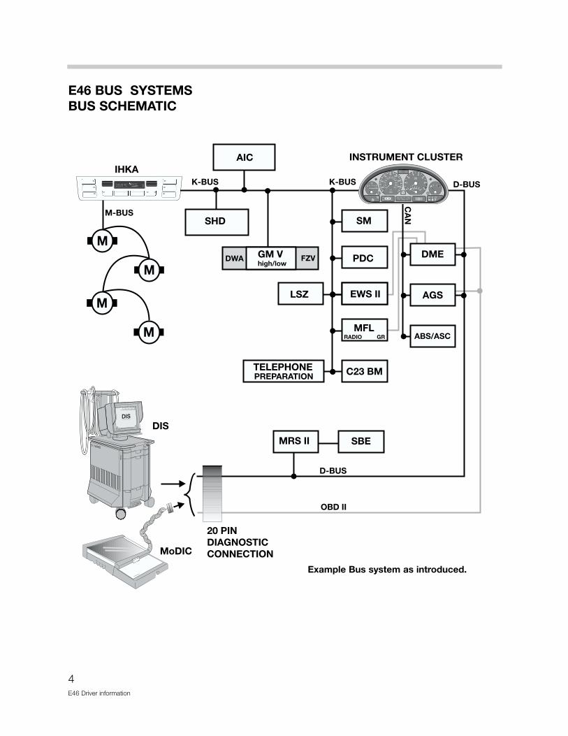
INSTRUMENT CLUSTER
The instrument cluster uses analog gauges for display of engine and road speed, enginetemperature, fuel level and economy display.
There are three LCD blocks for display of:
• The check control - pictogram
• The BC/Service interval and mileage
• The Transmission - range/program and failure display
Warning indicators and lamps are arranged to the right and left of the LCD blocks. TheASC, charge indicator, high beam and oil pressure lamps are located between thespeedometer and tachometer.
Features of the E46 cluster include:
• Stepper motor drives for the analog gauges
• New design Service Interval Indicator (SIA IV)
• Automatic transmission range/program display
The instrument cluster is a sealed unit and contains no serviceable components, other thanthe back lighting illumination bulbs.
UNLEADED GASOLINE ONLY
0
1 2
20
km/h
MPH
1/minx1000
40
60
80100
120 140160
180
200
220
240
1
0
23 4
5
6
750 30 20 1512
20
40
6080
100
120
1401 1

8E46 Driver information
CHECK CONTROL LCD MATRIX DISPLAY
The pictogram check control display carries over from the E39 for failure display warningsof various lights, doors/trunk open and low fluid indications. Inputs for warning lamp indi-cation are processed by the cluster electronics and the appropriate LED is illuminated.
RANGE/PROGRAM MATRIX DISPLAY
The right LCD matrix is used to display the driving range and program on vehicles equippedwith an automatic transmission. The transmission fault display is also integrated into thedisplay matrix. The gear with the explanation point will illuminate when the electronic con-trol of the transmission detects a fault.

9E46 Driver Information
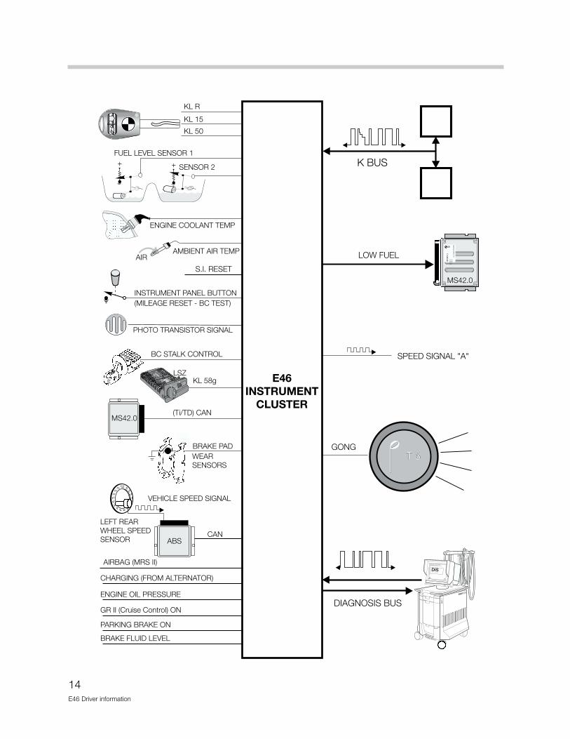
DYNAMIC DIGITAL INPUTS
DISTANCE SIGNAL- This input is supplied to the cluster by the ABS/ASC+T control mod-ule as a square wave signal. Pulses from the left rear wheel speed sensor are processedby the ABS module to produce this signal. The cluster electronics process the input for thecluster display and pass the signal along, on the K bus, as speed signal “A” for other con-trol modules requiring the vehicle speed signal.
CAN BUS SIGNALS- The “Ti” , engine temperature and “TD” signals are produced bythe DME control module and sent to the cluster. The cluster also passes the TD signalout over the K Bus.
TRANSMISSION DATA- The AGS control module provides the range selector position,driving program and fault lamp activation signals to the cluster over the CAN line.
OIL TEMPERATURE - This input is a pulse width modulated signal from the Electronic OilLevel Sensor. As oil level decreases the pulse width of the signal increases. If the signalshows an oil level that is too low over a period of time, the instrument cluster will illuminatethe Oil Warning indicator LED in yellow.
DIMMER SIGNAL - This is a pulse-width modulated signal from the LSZ. It is used to con-trol the intensity of the back lighting of the instruments and the LCDs when the lights areswitched ON. This signal is also output over the “K” Bus.
K-BUS SIGNALLING - The Cluster receives signals for the Check Control Pictogram overthe K-Bus.
DSC
CAN

10E46 Driver information
ANALOG INPUT SIGNALS
BATTERY VOLTAGE - Battery voltage is monitored by the cluster and a fault is stored ifthe voltage exceeds 16 volts
FUEL TANK LEVEL - Two lever action sensors are wired in parallel to the cluster. The twovarying voltage signals are processed by the cluster for fuel gauge and low fuel warningdisplay.
OUTSIDE TEMPERATURE SENSOR - A NTC sensor is used to measure the ambienttemperature. The signal is processed by the cluster and passed out over the K Bus to mod-ules requiring this input for processing.

11E46 Driver Information
DIGITAL INPUT SIGNALS
The normal ignition switch terminals (KL R, KL 15 & KL 50) are input to the cluster. Variousfunctions are dependent on ignition switch position.
STEERING COLUMN SWITCH - As with previous systems the turn signal stalk is used tocall up BC functions.
BRAKE PAD WEAR SENSORS - The pad sensor inputs are used to illuminate the brakepad warning indicator as in the past.
INSTRUMENT PANEL BUTTON - The reset button is used to reset the trip - odometeras in the past. It will also display the mileage, if pressed with the key switched OFF. Thisbutton is also used for the Base BC/instrument cluster test functions outlined on page 15.
INPUTS FOR WARNING LAMPS - Various switches are used to signal the cluster forwarning and indicator lamp illumination including:
WARNINGS FOR CONVERTIBLES • The seat belt warning lamp is illuminated when the seat belt is not fastened and
FLASHES when the front seat back is not locked into position.
• The Roll over Protection System warning lamp is illuminated when there is a fault in theRPS system.
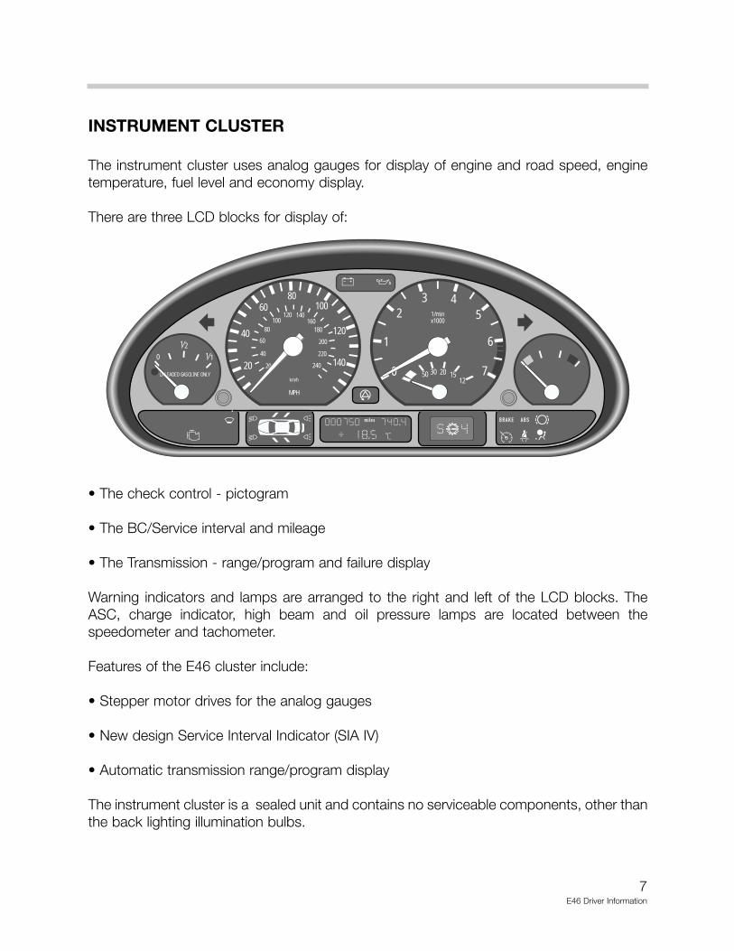
OUTPUT SIGNALS
SPEED SIGNAL “A” - The vehicle speed signal is available as an output for control mod-ules that require precise vehicle speed information.
“K” BUS INTERFACE - The K Bus is used to transfer data between the cluster and othermodules on the link. The diagnostic interface also passes over the K Bus for troubleshoot-ing with the DIS Tester.
LOW FUEL - Based on the processing for the low fuel indicator lamp, this output is alsosent to the DME control module. The signal is stored along with a mis-fire detection faultfor troubleshooting purposes.
GONG OUTPUT - T3, The T3 tone is used for check control warnings.
12E46 Driver information

REDUNDANT DATA STORAGE
Specific information is stored redundantly in the instrument cluster and in the Light SwitchModule. The data stored redundantly includes:
• VIN• Total Mileage• Service Interval data
The redundant storageof this information allowsfor the replacement of amodule without the lossof the total mileageaccumulated or the lossof the SI data.
The data is compared each time KL 15 is switched on. If the data does not match, themanipulation dot in the mileage display block will be illuminated.
The following points must be noted with regards to the redundant storage of this data.
1. If the vehicle ID number is not the same in both modules, the manipulation dot is illumi-nated. All functions of both modules continue to operate.
2. Data will only be transferred from the LSZ to the cluster if the ID numbers match and thecluster mileage is zero.
3. The VIN is entered in the cluster through coding and will only be accepted when the clus-ter mileage is zero.
4. The stored mileage in the LSZ can only be overwritten by a higher mileage.
5. If the two mileage values stored vary by more than 120, and the VINs are the same, thecluster will continue to accumulate mileage and a fault will be stored in the cluster fordata transfer.
6. If the K-Bus link fails, the cluster will continue to store mileage and set a fault for the Buslink.
New components should only be installed for replacement purposes and not for use as testcomponents for diagnosis as miles will accumulate if the vehicle is driven for road testingpurposes.
13E46 Driver Information
UNLEADED GASOLINE ONLY
0
1 2
20
km/h
MPH
1/minx1000
40
60
80100
120 140160
180
200
220
240
1
0
23 4
5
6
750 30 20 1512
20
40
6080
100
120
1401 1K-BUS
MANIPULATION DOT
LSZ
VIN
TOTAL MILEAGE
SERVICE INTERVALINFORMATION
VIN
TOTAL MILEAGE
SERVICE INTERVALINFORMATION
14E46 Driver information
15E46 Driver Information
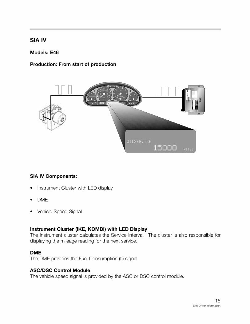
SIA IV
Models: E46
Production: From start of production
SIA IV Components:
• Instrument Cluster with LED display
• DME
• Vehicle Speed Signal
Instrument Cluster (IKE, KOMBI) with LED DisplayThe Instrument cluster calculates the Service Interval. The cluster is also responsible fordisplaying the mileage reading for the next service.
DMEThe DME provides the Fuel Consumption (ti) signal.
ASC/DSC Control ModuleThe vehicle speed signal is provided by the ASC or DSC control module.
UNLEADED GAS OLINE ONLY
0
12
20
km/h
MPH
1/min x1000
40
60
80100
120 140160
180
200
220
240
1
0
23 4
5
6
75030201512
20
40
6080
100
120
14011
Mmiles
����������
����� �� �
Ma
de in
Ge
rman
y
16E46 Driver information
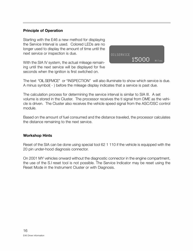
Principle of Operation
Starting with the E46 a new method for displayingthe Service Interval is used. Colored LEDs are nolonger used to display the amount of time until thenext service or inspection is due.
With the SIA IV system, the actual mileage remain-ing until the next service will be displayed for fiveseconds when the ignition is first switched on.
The text “OIL SERVICE” or “INSPECTION” will also illuminate to show which service is due.A minus symbol( - ) before the mileage display indicates that a service is past due.
The calculation process for determining the service interval is similar to SIA III. A set volume is stored in the Cluster. The processor receives the ti signal from DME as the vehi-cle is driven. The Cluster also receives the vehicle speed signal from the ASC/DSC controlmodule.
Based on the amount of fuel consumed and the distance traveled, the processor calculatesthe distance remaining to the next service.
Workshop Hints
Reset of the SIA can be done using special tool 62 1 110 if the vehicle is equipped with the20 pin under-hood diagnosis connector.
On 2001 MY vehicles onward without the diagnostic connector in the engine compartment,the use of the S.I reset tool is not possible. The Service Indicator may be reset using theReset Mode in the Instrument Cluster or with Diagnosis.
����������
����� �� �

17E46 Driver Information
Reset procedure using the Reset Mode. (possible from 9/99 onward for E46, MY2001 E52)
• Ignition key must be “off”
• Press and hold the trip odometer button in the instrument cluster (left button), and turnthe ignition key to the first position (KLR).
• Keep the button pressed for approximately 5 seconds until one of the following wordsappear in the display: “OIL SERVICE, or “INSPECTION”, with “reset”.
• Release the reset button and press and hold it again until “reset” begins to flash.
• While the display is flashing, press the left button briefly to reset the service interval. After the display has shown the new interval, the following will appear: “END SIA”
The system can only be reset again after 10 liters (2.5gal) of fuel have been consumed.
����������
����� �� �
UNLEADED GASOLINE ONLY
0
12
20
km/h
MPH
1/min x1000
40
60
80100
120 140160
180
200
220
240
1
0
23 4
5
6
7503020 1512
20
40
6080
100
120
14011
Mmiles
����� �� �� ��
12
TURN KEY TO POSITION1 (KLR)
PRESS ANDHOLD LEFTBUTTON
KEEP PRESSEDFOR 5 SECONDSAFTER KEY ISSWITCHED ON.
TAP BUTTON TORESET SI DISPLAY
E46 service interval reset
18E46 Driver information
Reset using Diagnosis Program • Connect the Diagnosis head to the diagnostic connector of the vehicle.
• Identify the vehicle and perform the Short Test.
• Select Function Selection and then Service Functions.
• Highlight Reset Service Interval Indicator (Test module S6211-00001)
• Select with tester.
• Follow the directions from the help information in the test module (upper right corner).
• Select which service is to be reset and press the continue key.
• An acknowledgement is displayed on the screen that the reset has been carried out.
Instrument Cluster ReplacementIf the instrument cluster (Kombi) is replaced the SI data can be retrieved from the LSZ onE46 vehicles and from the LCM III on the E52. Coding procedures are the same as SIA II.
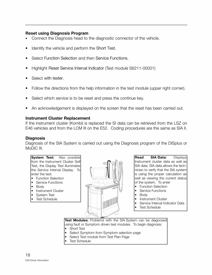
Diagnosis Diagnosis of the SIA System is carried out using the Diagnosis program of the DISplus orMoDiC III.
System Test: Also possiblefrom the Instrument Cluster SelfTest, the Display Test illuminatesthe Service Interval Display. Toenter the test:• Function Selection• Service Functions• Body• Instrument Cluster• System Test• Test Schedule
Test Modules: Problems with the SIA System can be diagnosedusing fault or Symptom driven test modules. To begin diagnosis:• Short Test• Select Symptom from Symptom selection page• Select Test module from Test Plan Page• Test Schedule
Read SIA Data: DisplaysInstrument cluster data as well asSIA data. SIA data allows the tech-nician to verify that the SIA systemis using the proper calculation aswell as viewing the current statusof the system. To enter • Function Selection• Service Functions• Body• Instrument Cluster• Service Interval Indicator Data• Test Schedule
19E46 Driver Information
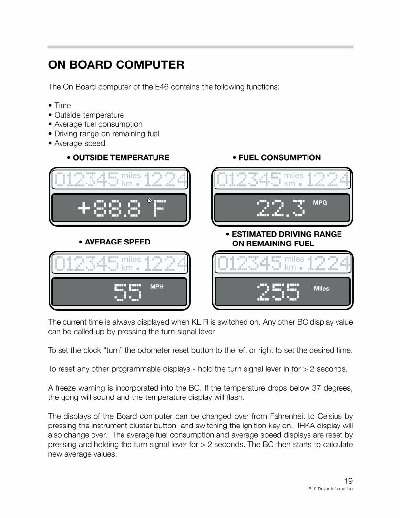
ON BOARD COMPUTER
The On Board computer of the E46 contains the following functions:
• Time• Outside temperature• Average fuel consumption• Driving range on remaining fuel• Average speed
The current time is always displayed when KL R is switched on. Any other BC display valuecan be called up by pressing the turn signal lever.
To set the clock “turn” the odometer reset button to the left or right to set the desired time.
To reset any other programmable displays - hold the turn signal lever in for > 2 seconds.
A freeze warning is incorporated into the BC. If the temperature drops below 37 degrees,the gong will sound and the temperature display will flash.
The displays of the Board computer can be changed over from Fahrenheit to Celsius bypressing the instrument cluster button and switching the ignition key on. IHKA display willalso change over. The average fuel consumption and average speed displays are reset bypressing and holding the turn signal lever for > 2 seconds. The BC then starts to calculatenew average values.
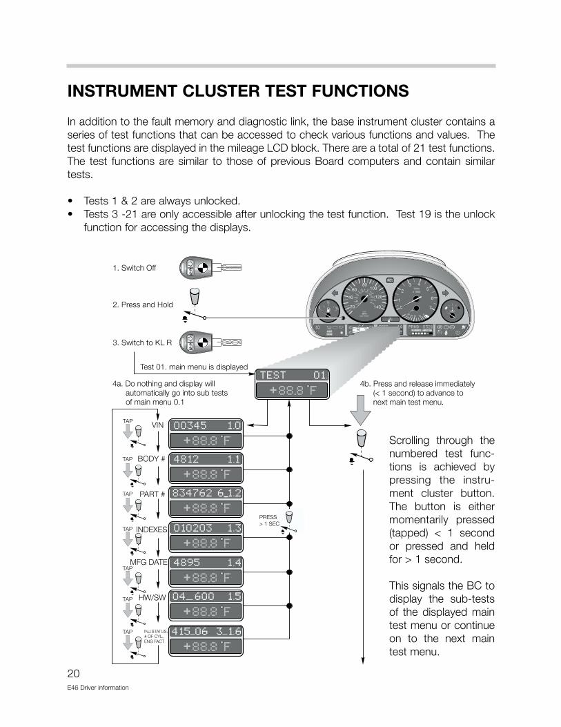
INSTRUMENT CLUSTER TEST FUNCTIONS
In addition to the fault memory and diagnostic link, the base instrument cluster contains aseries of test functions that can be accessed to check various functions and values. Thetest functions are displayed in the mileage LCD block. There are a total of 21 test functions.The test functions are similar to those of previous Board computers and contain similartests.
• Tests 1 & 2 are always unlocked.• Tests 3 -21 are only accessible after unlocking the test function. Test 19 is the unlock
function for accessing the displays.
20E46 Driver information
Scrolling through thenumbered test func-tions is achieved bypressing the instru-ment cluster button.The button is eithermomentarily pressed(tapped) < 1 secondor pressed and heldfor > 1 second.
This signals the BC todisplay the sub-testsof the displayed maintest menu or continueon to the next maintest menu.
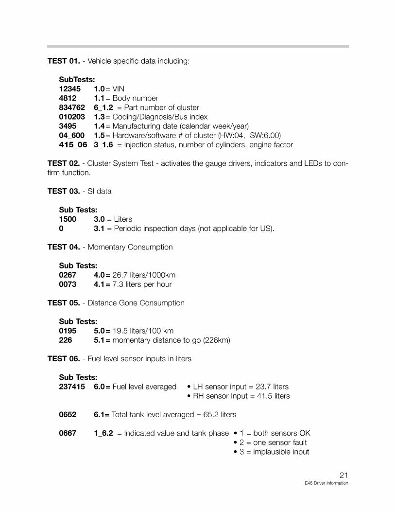
TEST 01. - Vehicle specific data including:
SubTests:12345 1.0= VIN 4812 1.1= Body number834762 6_1.2 = Part number of cluster010203 1.3= Coding/Diagnosis/Bus index3495 1.4= Manufacturing date (calendar week/year)04_600 1.5= Hardware/software # of cluster (HW:04, SW:6.00)415_06 3_1.6 = Injection status, number of cylinders, engine factor
TEST 02. - Cluster System Test - activates the gauge drivers, indicators and LEDs to con-firm function.
TEST 03. - SI data
Sub Tests:1500 3.0 = Liters0 3.1 = Periodic inspection days (not applicable for US).
TEST 04. - Momentary Consumption
Sub Tests:0267 4.0= 26.7 liters/1000km0073 4.1= 7.3 liters per hour
TEST 05. - Distance Gone Consumption
Sub Tests:0195 5.0= 19.5 liters/100 km226 5.1= momentary distance to go (226km)
TEST 06. - Fuel level sensor inputs in liters
Sub Tests:237415 6.0= Fuel level averaged • LH sensor input = 23.7 liters
• RH sensor Input = 41.5 liters
0652 6.1= Total tank level averaged = 65.2 liters
0667 1_6.2 = Indicated value and tank phase • 1 = both sensors OK• 2 = one sensor fault• 3 = implausible input
21E46 Driver Information
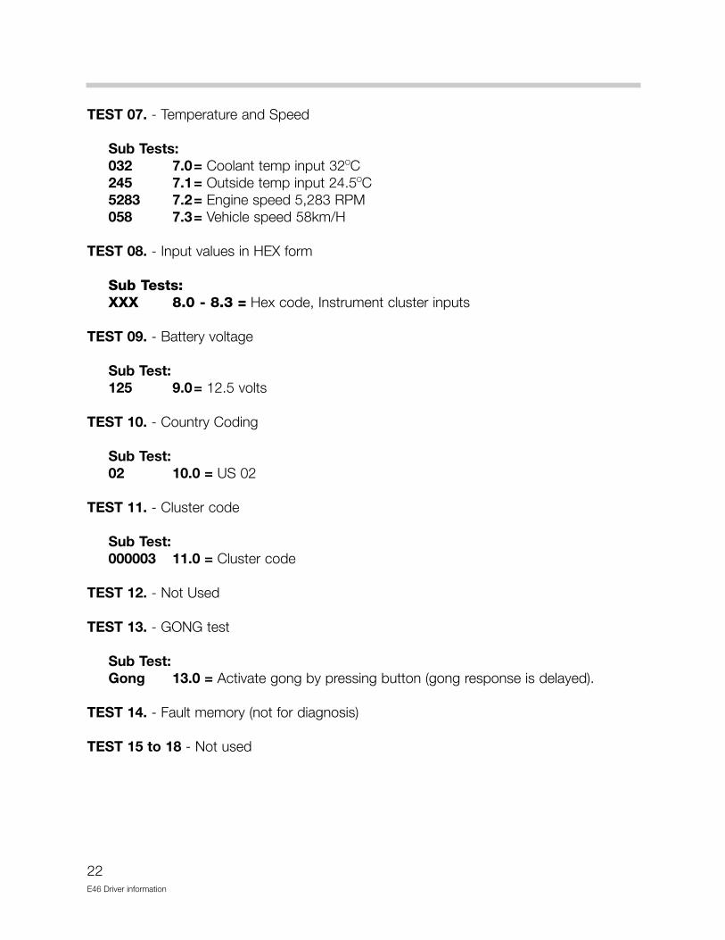
TEST 07. - Temperature and Speed
Sub Tests:032 7.0= Coolant temp input 32OC245 7.1= Outside temp input 24.5OC5283 7.2= Engine speed 5,283 RPM058 7.3= Vehicle speed 58km/H
TEST 08. - Input values in HEX form
Sub Tests:XXX 8.0 - 8.3 = Hex code, Instrument cluster inputs
TEST 09. - Battery voltage
Sub Test:125 9.0= 12.5 volts
TEST 10. - Country Coding
Sub Test:02 10.0 = US 02
TEST 11. - Cluster code
Sub Test:000003 11.0 = Cluster code
TEST 12. - Not Used
TEST 13. - GONG test
Sub Test:Gong 13.0 = Activate gong by pressing button (gong response is delayed).
TEST 14. - Fault memory (not for diagnosis)
TEST 15 to 18 - Not used
22E46 Driver information
23E46 Driver Information
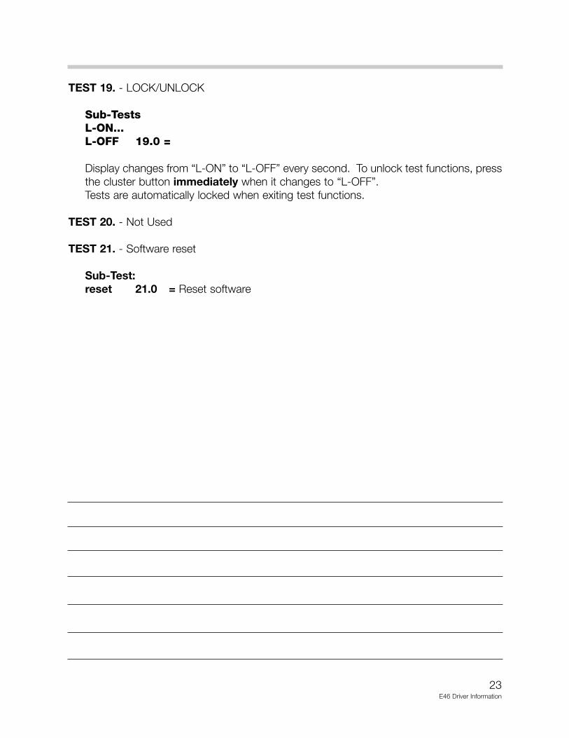
TEST 19. - LOCK/UNLOCK
Sub-TestsL-ON...L-OFF 19.0 =
Display changes from “L-ON” to “L-OFF” every second. To unlock test functions, pressthe cluster button immediately when it changes to “L-OFF”.Tests are automatically locked when exiting test functions.
TEST 20. - Not Used
TEST 21. - Software reset
Sub-Test:reset 21.0 = Reset software

24E46 Driver information
LIGHT SWITCH CENTER (LSZ)
The Light Switch Center is a compact component that combines the electronic control,switching, and monitoring for all exterior lighting on the E46. In addition the LSZ controlsthe illumination and intensity of the instrument cluster lighting and LCD blocks. The LSZassembly is mounted in the dash and consists of two serviceable components; theswitch assembly and the control module.
The LSZ provides the functions of the LCM including:
• Hot and cold monitoring of the exterior lights.• Emergency lighting function• Short circuit protection• Redundant storage of mileage and SI data
The total scope of the LSZ system includes the following:
• LSZ control module• LSZ switch assembly• High-low beam/turn signal switch• Brake light switch• Hazard warning light switch• Fog light relay• Exterior lights• Dash/LCD lighting
UNLEADED GASOLINE ONLY
0
1 2
20
km/h
MPH
1/minx1000
40
60
80100
120 140160
180
200
220
240
1
0
23 4
5
6
750 30 20 1512
20
40
6080
100
120
1401 1
LSZ
K-BUSGM V
AGS DATA LINK
BULB MONITORING BULB ACTIVATION
LSZ
COMPONENT OPERATION
The LSZ control module receives inputs from the following switches:
Headlight/parking light switch, fog light switch, potentiometer and photo-transistor mount-ed in the LSZ switch assembly.
• These inputs are received directly from the LSZ switch assembly.
TURN SIGNAL/HIGHBEAM SWITCH
• The turn signal and headlight (high/low) beam are resistance coded inputs over two wiresto the LSZ control module. The LSZ carries out the switching function based on the volt-age drop input.
HAZARD WARNING SWITCH
• The hazard switch provides a ground input to the LSZ to control the operation of the haz-ard warning lights.
• The hazard warning lights will be switched on in the event of an accident from the crashsensor input provided by the MRS control module.
BRAKE LIGHT SWITCH
• The brake light switch is a hall sensor that receives power when KL R is switched on. Theswitch is low until the brake pedal is pressed. When the LSZ receives a high signal fromthe switch the brake lights are switched on.
• If the hall sensor fails, the brake lights will be switched on continuously.
25E46 Driver Information
26E46 Driver Information
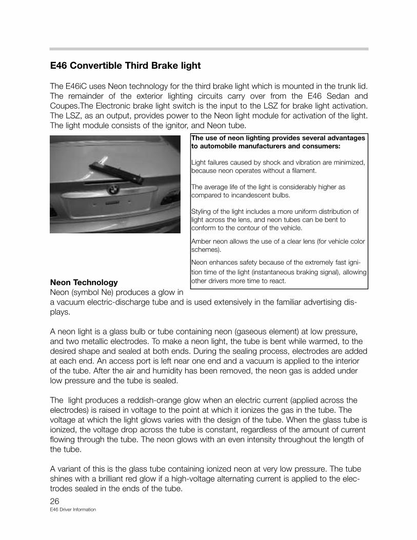
E46 Convertible Third Brake light
The E46iC uses Neon technology for the third brake light which is mounted in the trunk lid.The remainder of the exterior lighting circuits carry over from the E46 Sedan andCoupes.The Electronic brake light switch is the input to the LSZ for brake light activation.The LSZ, as an output, provides power to the Neon light module for activation of the light.The light module consists of the ignitor, and Neon tube.
Neon TechnologyNeon (symbol Ne) produces a glow ina vacuum electric-discharge tube and is used extensively in the familiar advertising dis-plays.
A neon light is a glass bulb or tube containing neon (gaseous element) at low pressure,and two metallic electrodes. To make a neon light, the tube is bent while warmed, to thedesired shape and sealed at both ends. During the sealing process, electrodes are addedat each end. An access port is left near one end and a vacuum is applied to the interiorof the tube. After the air and humidity has been removed, the neon gas is added underlow pressure and the tube is sealed.
The light produces a reddish-orange glow when an electric current (applied across theelectrodes) is raised in voltage to the point at which it ionizes the gas in the tube. Thevoltage at which the light glows varies with the design of the tube. When the glass tube isionized, the voltage drop across the tube is constant, regardless of the amount of currentflowing through the tube. The neon glows with an even intensity throughout the length ofthe tube.
A variant of this is the glass tube containing ionized neon at very low pressure. The tubeshines with a brilliant red glow if a high-voltage alternating current is applied to the elec-trodes sealed in the ends of the tube.
The use of neon lighting provides several advantagesto automobile manufacturers and consumers:
Light failures caused by shock and vibration are minimized,because neon operates without a filament.
The average life of the light is considerably higher ascompared to incandescent bulbs.
Styling of the light includes a more uniform distribution oflight across the lens, and neon tubes can be bent toconform to the contour of the vehicle.
Amber neon allows the use of a clear lens (for vehicle colorschemes).
Neon enhances safety because of the extremely fast igni-tion time of the light (instantaneous braking signal), allowingother drivers more time to react.

LAMP MONITORING
Lamp monitoring on the E46 is a function of the LSZ control module. The following lampsare monitored in both the hot and cold states:
• High/low beams• Brake lights - left/right• Turn signal lights• Tail lights• Parking lights• Side marker lights• License plate lights
Hot monitoring takes place when the lights are switched by monitoring the current flowthrough the lamp filaments.
Cold monitoring takes place by the LSZ when the lights are switched off. The LSZ will brieflyactivate the lighting circuits and check for current flow through the lamps. The lights are notswitched on long enough to illuminate the bulbs.
If the LSZ detects a defective bulb, a signal is sent to the instrument cluster and the warn-ing is posted in the Check Control pictogram.
27E46 Driver information
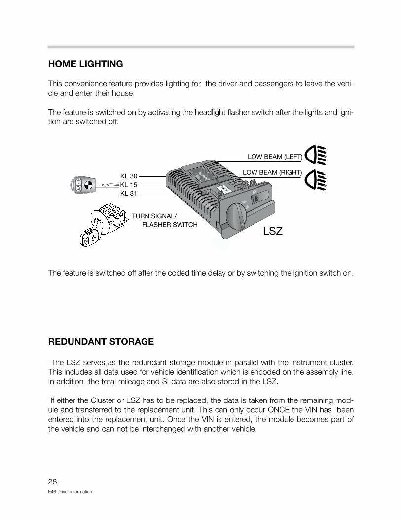
HOME LIGHTING
This convenience feature provides lighting for the driver and passengers to leave the vehi-cle and enter their house.
The feature is switched on by activating the headlight flasher switch after the lights and igni-tion are switched off.
The feature is switched off after the coded time delay or by switching the ignition switch on.
REDUNDANT STORAGE
The LSZ serves as the redundant storage module in parallel with the instrument cluster.This includes all data used for vehicle identification which is encoded on the assembly line.In addition the total mileage and SI data are also stored in the LSZ.
If either the Cluster or LSZ has to be replaced, the data is taken from the remaining mod-ule and transferred to the replacement unit. This can only occur ONCE the VIN has beenentered into the replacement unit. Once the VIN is entered, the module becomes part ofthe vehicle and can not be interchanged with another vehicle.
28E46 Driver information
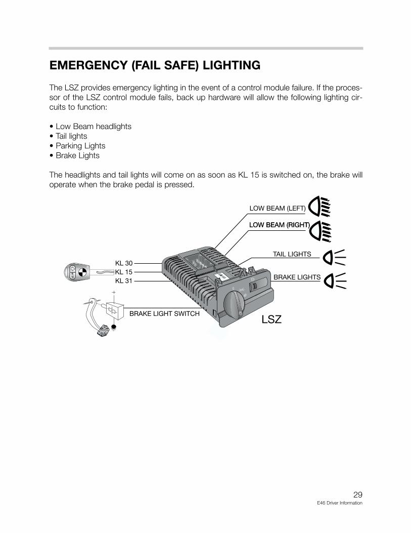
EMERGENCY (FAIL SAFE) LIGHTING
The LSZ provides emergency lighting in the event of a control module failure. If the proces-sor of the LSZ control module fails, back up hardware will allow the following lighting cir-cuits to function:
• Low Beam headlights• Tail lights• Parking Lights• Brake Lights
The headlights and tail lights will come on as soon as KL 15 is switched on, the brake willoperate when the brake pedal is pressed.
29E46 Driver Information

30E46 Driver Information
XENON HEADLIGHTS
OVERVIEW
The automotive industry/press often identify xenon lighting systems as HID (high intensitydischarge) systems. Xenon headlight technology was first introduced to the US marketexclusively on the E32 750iL in 1993. BMW xenon headlight systems have evolved andtheir availability as optional equipment has spread throughout the model lineup.
Blue/White in color and using ellipsoidal technology Xenon headlights provide improvednight time visibility in all driving conditions compared with traditional Halogen bulb head-lights.
BENEFITS:
Xenon headlights provide the following benefits:
• Longer bulb life. Typically, xenon bulbs will last from 3 to 5 times longer than halogen.
• More light output. Xenon headlights produce from 2.5 to 3 times more lumens thanhalogen.
• Blue/White light (simulates natural daylight). Xenon bulbs produce a blue/white lightwhile halogen bulbs produce a yellow light. The light color of a light source is measuredin color temperature (not to be confused with thermal temperature). Color temperatureis measured in Kelvins (K). The higher the color temperature the whiter the light.
Natural daylight = 4,500 to 5,000 KXenon headlights = 4,000 to 4,500 KHalogen headlights = 3,200 K (yellow in color)
• Better driving visibility.The combination of higherlumens and higher colortemperature provide a supe-rior lighting source.
The beam is wider andbrighter in front of the vehi-cle than conventional halo-gen bulbs improving safetyand driver comfort.

31E46 Driver Information
VERSION IDENTIFICATION & SYSTEM SUMMARIES
Version identification is specific to vehicle model with the exception of the E38.
There are two E38 Xenon systems. The early sys-tem identified as Generation 2.1 and equipped on95-98 model year 750iL vehicles. The headlightdesign of this version has a flat bottom edge.
The Generation 3 system has been introduced on1999 model year E38 vehicles. This system can bevisually identified by the rounded bottom edge ofthe headlight assembly.
LWR: All 1999 model year systems are also equipped with LWR (Headlight Beam ThrowControl). This system automatically adjusts the vertical position of the headlight beams tocompensate for vehicle loads ensuring optimum beam throw. LWR components and func-tion is described further on in this section.
Headlight Replacement Parts: In previous model years, individual replacement partswere not available for headlight assemblies. This was due to the Federal Motor VehicleSafety Standards (FMVSS) relating to pitting or corrosion of the reflector components innon-sealed beam light assemblies.
BMW has submitted corrosion test data for headlight replacement components which havepassed the FMVSS providing availability of headlight assembly spare parts. The approvalhas been given for all Bosch headlight assemblies (including halogen systems).
E46 Headlight
Vehicle/ Model Manufacturer(s)/ LWR- Head IndividualModel Year Version ID Light Beam Replacement
Throw Cont. Parts Available
E32/ 93-94 Hella (Light & No No750iL CM ”control module”)
Generation 1
E38/ 95-98 Bosch (Light & CM) No Yes750iL Generation 2.1
E38/ 99- Bosch (light) Yes YesAll Hella (CM)
Generation 3
E39 99- Hella Yes NoAll Generation 3
E46 99- Bosch (Light & CM) Yes Yes
32E46 Driver Information
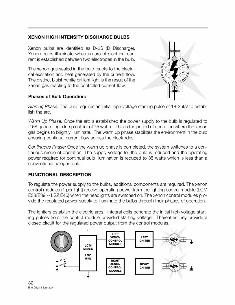
XENON HIGH INTENSITY DISCHARGE BULBS
Xenon bulbs are identified as D-2S (D=Discharge).Xenon bulbs illuminate when an arc of electrical cur-rent is established between two electrodes in the bulb.
The xenon gas sealed in the bulb reacts to the electri-cal excitation and heat generated by the current flow.The distinct bluish/white brilliant light is the result of thexenon gas reacting to the controlled current flow.
Phases of Bulb Operation:
Starting Phase: The bulb requires an initial high voltage starting pulse of 18-25kV to estab-lish the arc.
Warm Up Phase: Once the arc is established the power supply to the bulb is regulated to2.6A generating a lamp output of 75 watts. This is the period of operation where the xenongas begins to brightly illuminate. The warm up phase stabilizes the environment in the bulbensuring continual current flow across the electrodes.
Continuous Phase: Once the warm up phase is completed, the system switches to a con-tinuous mode of operation. The supply voltage for the bulb is reduced and the operatingpower required for continual bulb illumination is reduced to 35 watts which is less than aconventional halogen bulb.
FUNCTIONAL DESCRIPTION
To regulate the power supply to the bulbs, additional components are required. The xenoncontrol modules (1 per light) receive operating power from the lighting control module (LCME38/E39 -- LSZ E46) when the headlights are switched on. The xenon control modules pro-vide the regulated power supply to illuminate the bulbs through their phases of operation.
The igniters establish the electric arcs. Integral coils generate the initial high voltage start-ing pulses from the control module provided starting voltage. Thereafter they provide aclosed circuit for the regulated power output from the control modules.

33E46 Driver Information
XENON BULB MONITORING
Xenon bulb function is monitored by the Lighting Control Module (LCM E38/E39 -- LSZE46). The bulbs are only “hot” monitored. Cold monitoring is not possible since the light-ing control module is not in direct control of the xenon bulb. For this reason cold monitor-ing for low beam headlights is encoded off in the lighting control module for Xenon head-light equipped vehicle.
The lighting control module detects xenon bulb failure via a reduction in current flow to thexenon control module. When a bulb fails, the xenon control module’s current consumptiondrops to 60mA indicating unsuccessful xenon bulb illumination. The lighting control mod-ule then posts the appropriate matrix display message or LED illumination in the CheckControl Pictogram display of the E46 and E39 Low Instrument Clusters.
XENON HEADLIGHT ASSEMBLY COMPONENTS (Example - E46)
Xenon Control Module
LWR Stepper Motor
Replaceable Lens Cover
Light Frame Assembly
Gasket Seal
Xenon ControlModule Cover
Rubber Cover Boot
Igniter
D-2S Xenon Bulb(Low Beam)
H-7 Halogen Bulb(High Beam)
34E46 Driver Information
DIAGNOSIS
Xenon control modules are not connected to the diagnostic link. However, the vehicle spe-cific Lighting Control Module (E38/E39 - LCM or E46 - LSZ) does incorporate xenon head-light specific diagnosis up to the xenon control module.
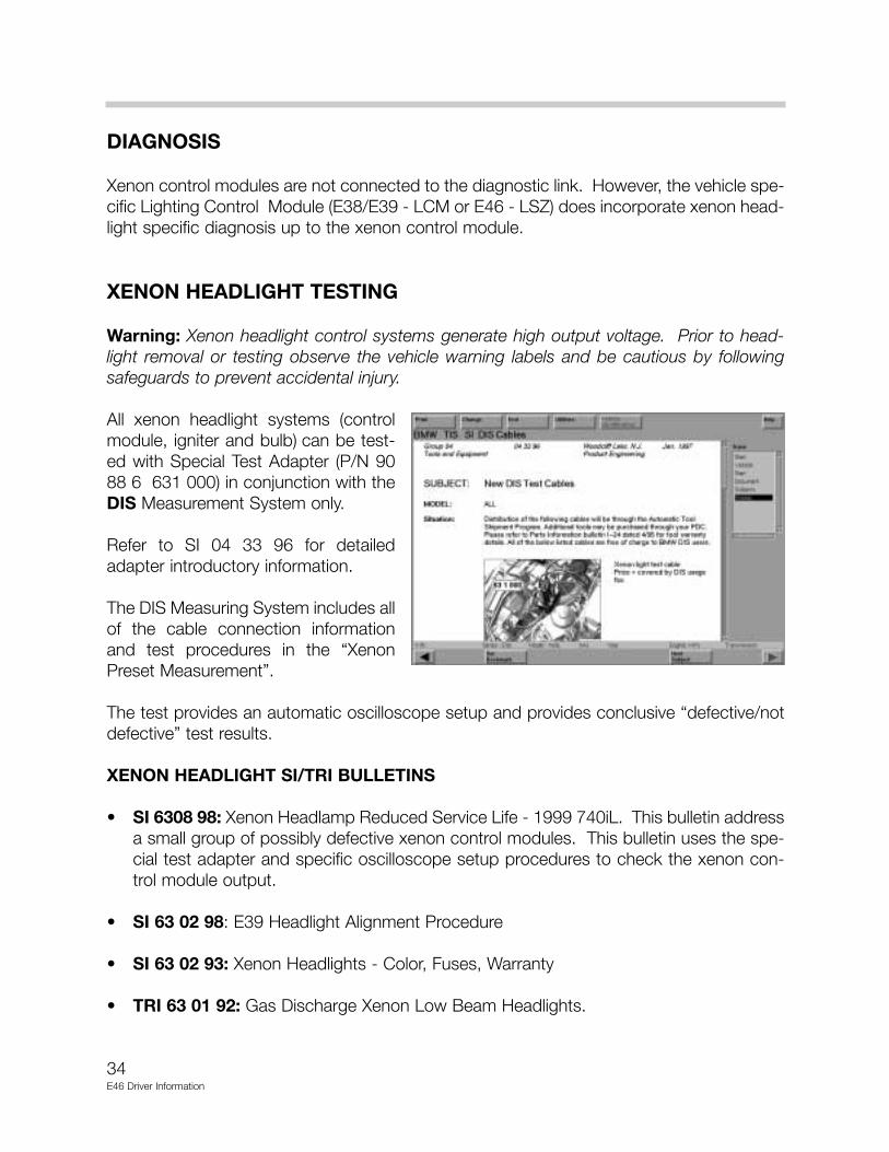
XENON HEADLIGHT TESTING
Warning: Xenon headlight control systems generate high output voltage. Prior to head-light removal or testing observe the vehicle warning labels and be cautious by followingsafeguards to prevent accidental injury.
All xenon headlight systems (controlmodule, igniter and bulb) can be test-ed with Special Test Adapter (P/N 9088 6 631 000) in conjunction with theDIS Measurement System only.
Refer to SI 04 33 96 for detailedadapter introductory information.
The DIS Measuring System includes allof the cable connection informationand test procedures in the “XenonPreset Measurement”.
The test provides an automatic oscilloscope setup and provides conclusive “defective/notdefective” test results.
XENON HEADLIGHT SI/TRI BULLETINS
• SI 6308 98: Xenon Headlamp Reduced Service Life - 1999 740iL. This bulletin addressa small group of possibly defective xenon control modules. This bulletin uses the spe-cial test adapter and specific oscilloscope setup procedures to check the xenon con-trol module output.
• SI 63 02 98: E39 Headlight Alignment Procedure
• SI 63 02 93: Xenon Headlights - Color, Fuses, Warranty
• TRI 63 01 92: Gas Discharge Xenon Low Beam Headlights.
35E46 Driver Information
HEADLIGHT BEAM THROW CONTROL- LWR
OVERVIEW
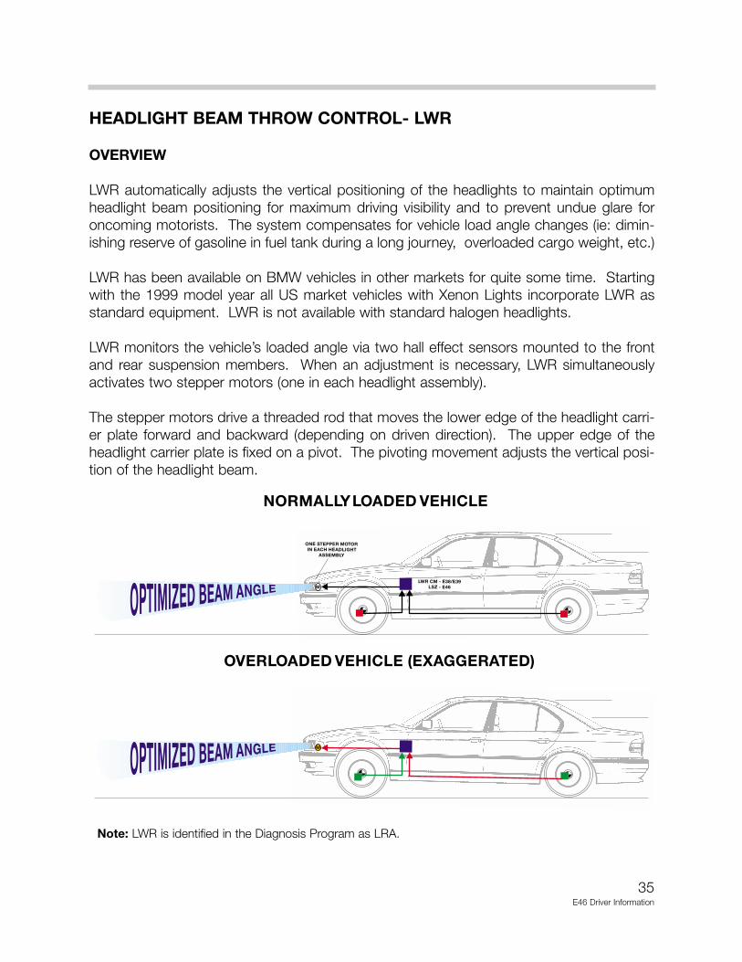
LWR automatically adjusts the vertical positioning of the headlights to maintain optimumheadlight beam positioning for maximum driving visibility and to prevent undue glare foroncoming motorists. The system compensates for vehicle load angle changes (ie: dimin-ishing reserve of gasoline in fuel tank during a long journey, overloaded cargo weight, etc.)
LWR has been available on BMW vehicles in other markets for quite some time. Startingwith the 1999 model year all US market vehicles with Xenon Lights incorporate LWR asstandard equipment. LWR is not available with standard halogen headlights.
LWR monitors the vehicle’s loaded angle via two hall effect sensors mounted to the frontand rear suspension members. When an adjustment is necessary, LWR simultaneouslyactivates two stepper motors (one in each headlight assembly).
The stepper motors drive a threaded rod that moves the lower edge of the headlight carri-er plate forward and backward (depending on driven direction). The upper edge of theheadlight carrier plate is fixed on a pivot. The pivoting movement adjusts the vertical posi-tion of the headlight beam.
Note: LWR is identified in the Diagnosis Program as LRA.

36E46 Driver Information
LWR COMPONENTS
CONTROL ELECTRONICS
LSZ - E46
The E46 LWR function is integrated into the control electronics of the LSZ. The LSZ mon-itors the required input signals to provide the LWR function and directly activates the step-per motors in the headlight assemblies. All LWR diagnosis is accessed through the LSZcontrol module.
LEVEL SENSORS
LWR monitors two hall effect level sensors todetermine vehicle load angle. The sensorsare mounted to a fixed point on the suspen-sion carriers of the front and rear axles.
A lever is connected to the moving suspen-sion member which changes the sensors out-put linear voltage signal as the suspensionmoves up and down.
HEADLIGHT ADJUSTMENT STEPPER MOTORS
One stepper motor is located inside eachheadlight assembly.
The 4 wire stepper motors are controlledby the LWR control electronics to changethe vertical headlight position.
37E46 Driver Information
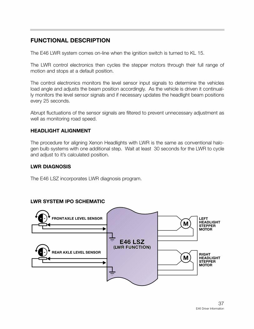
FUNCTIONAL DESCRIPTION
The E46 LWR system comes on-line when the ignition switch is turned to KL 15.
The LWR control electronics then cycles the stepper motors through their full range ofmotion and stops at a default position.
The control electronics monitors the level sensor input signals to determine the vehiclesload angle and adjusts the beam position accordingly. As the vehicle is driven it continual-ly monitors the level sensor signals and if necessary updates the headlight beam positionsevery 25 seconds.
Abrupt fluctuations of the sensor signals are filtered to prevent unnecessary adjustment aswell as monitoring road speed.
HEADLIGHT ALIGNMENT
The procedure for aligning Xenon Headlights with LWR is the same as conventional halo-gen bulb systems with one additional step. Wait at least 30 seconds for the LWR to cycleand adjust to it’s calculated position.
LWR DIAGNOSIS
The E46 LSZ incorporates LWR diagnosis program.
LWR SYSTEM IPO SCHEMATIC

MULTI-FUNCTION STEERING WHEEL
The multi-function steering wheel of the E46 corresponds to the MFL introduced on the E38and carried over to the E39. The wheel contains two key pads on the left and right side ofthe air bag that allow activation and control of various driver convince systems.
As with previous MFLs, the left side key pad contains controls for the sound system andtelephone. The right side key pad contains the controls for the cruise control.
The K-Bus is used for data communication between the sound system/telephone controls.The cruise control has its own data link to the DME control module for cruise control oper-ation.
38E46 Driver information