Embed Size (px)
Citation preview
Chapter 2 Outline Design of the Requested Japanese Assistance
B-50
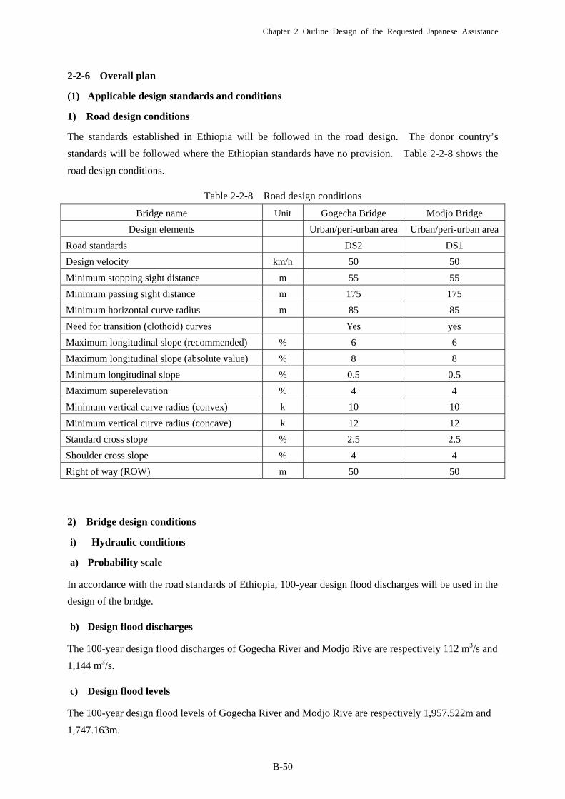
2-2-6 Overall plan
(1) Applicable design standards and conditions
1) Road design conditions
The standards established in Ethiopia will be followed in the road design. The donor country’s
standards will be followed where the Ethiopian standards have no provision. Table 2-2-8 shows the
road design conditions.
Table 2-2-8 Road design conditions
Bridge name Unit Gogecha Bridge Modjo Bridge
Design elements Urban/peri-urban area Urban/peri-urban area
Road standards DS2 DS1
Design velocity km/h 50 50
Minimum stopping sight distance m 55 55
Minimum passing sight distance m 175 175
Minimum horizontal curve radius m 85 85
Need for transition (clothoid) curves Yes yes
Maximum longitudinal slope (recommended) % 6 6
Maximum longitudinal slope (absolute value) % 8 8
Minimum longitudinal slope % 0.5 0.5
Maximum superelevation % 4 4
Minimum vertical curve radius (convex) k 10 10
Minimum vertical curve radius (concave) k 12 12
Standard cross slope % 2.5 2.5
Shoulder cross slope % 4 4
Right of way (ROW) m 50 50
2) Bridge design conditions
i) Hydraulic conditions
a) Probability scale
In accordance with the road standards of Ethiopia, 100-year design flood discharges will be used in the
design of the bridge.
b) Design flood discharges
The 100-year design flood discharges of Gogecha River and Modjo Rive are respectively 112 m3/s and
1,144 m3/s.
c) Design flood levels
The 100-year design flood levels of Gogecha River and Modjo Rive are respectively 1,957.522m and
1,747.163m.

Chapter 2 Outline Design of the Requested Japanese Assistance
B-51
d) Vertical clearances
The table below shows the vertical clearances stipulated in Bridge Design Manual (2002) of Ethiopia.
The table below shows the vertical clearance required for the two bridges derived from the table
above.
Table 2-2-9 Design flood discharges and vertical clearances
Gogecha Bridge Modjo Bridge
Design flood discharge (m3/s) 112 1,144
Vertical clearance (m) 0.9 1.2
e) Scour depth
The designs of Gogecha and Modjo Bridges include abutments and piers, respectively, in the river
channels. However, since bedrock is exposed on the banks of both the Gogecha and Modjo Rivers,
floods will pose no possibility of scour in future. Nonetheless, the scour depth of 2 m will be
included in the bridge designs as a standard.
f) Revetment
The river which the planned bridge is to be built is natural river. The river channel has not been
altered artificially and there is no embankment along the river. There is no revetment or bed
protection work near the abutments or piers of the existing bridge or on the river banks upstream or
downstream of the bridge. Bedrock is exposed on the river banks where the bridge exists. There
are limited amounts of earth and stone sediment transported from the upper reaches of the river and
tributaries upstream and downstream of the current bridge sites. Therefore, there is no possibility of
river-bed variation caused by scour at the time of flood. In order to ensure safe and smooth flow of
flood water as has been seen up to now after the bridge construction, the revetment work focused on
restoration of the original conditions will be considered.
ii) Design live loads
As described in 2-1-5, Policies on Design Live Load, the figure 25 % larger than HS20 stipulated in
the Ethiopian standards (Bridge Design Manual: 2002) based on AASHTO will be used as the design
live load on the bridges.
iii) Seismic load
Ethiopia has Bridge Design Manual: 2002, which stipulated the seismic loads as follows:

Chapter 2 Outline Design of the Requested Japanese Assistance
B-52
a) Earthquake zones
The entire country is classified into five earthquake zones, to , and the two bridges concerned are
located in Zone .
Figure 3-9 Earthquake Zones (Note: In zone 1-3 A0.07 and in zone 4 A0.10)
b) Response acceleration coefficient
Among the five earthquake zones, a response acceleration coefficient has been provided for each of
the Zones 1 to 4, as shown in the table below. The coefficient for the three bridges concerned was set
at A = 0.10 with safety allowance.
EBCS zone from Figure 3-9 Acceleration Coefficient 1 A 0.032 0.03 < A 0.053 0.05 < A 0.074 0.07 < A 0.10
c) Horizontal seismic vibration
Horizontal seismic vibration is obtained from the following equation:
Cm=1.2AS/Tm2/3 ≦2.5A,
where:
Cm: Horizontal seismic vibration,
A: Response acceleration coefficient = 0.10,
S: Site coefficient = 1.0 (in accordance with the table below) and
Site
Coefficient
Soil Profile Type
I II III IV
S 1.0 1.2 1.5 2.0
Tm: Natural period of structure.
The maximum vibration of Cm = 2.5A = 2.5 x 0.1 = 0.25 obtained from the equation above with
safety allowance will be used in the design.
Chapter 2 Outline Design of the Requested Japanese Assistance
B-53
iv) Material strengths
Table below shows the strengths of various materials to be used in this project.
Table 2-2-10 Materials to be used
Gogecha Bridge Modjo Bridge
1) PC concrete
・Main girder σck=35N/mm2 ・Cross beam and filling concrete σck=30N/mm2
・Main girder σck=35N/mm2
2) RC concrete ・Sleepers and substructure work
σck=24N/mm2
・Sleepers and substructure work σck=24N/mm2
・Cast-in-place piles (underwater) σck=30N/mm2
3) Plain concrete
・Sidewalks leveling concrete σck=18N/mm2
・Sidewalks leveling concrete σck=18N/mm2
4) Reinforcing bars SD345 SD345
5) PC steel materials
・Main cable 12S12.7 (SWPR7BL)
・Transverse prestressing cable 1S19.3 (SWPR19L)
・Main cable 12S12.7 (SWPR7BL)
・Transverse prestressing cable 1S28.6 (SWPR19L)
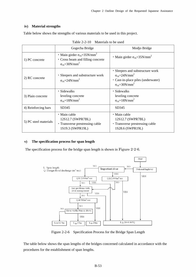
v) The specification process for span length
The specification process for the bridge span length is shown in Figure 2-2-6.
Figure 2-2-6 Specification Process for the Bridge Span Length
The table below shows the span lengths of the bridges concerned calculated in accordance with the
procedures for the establishment of span lengths.
Chapter 2 Outline Design of the Requested Japanese Assistance
B-54
Table 2-2-11 Span lengths
(2) Road width plan
The widths of the bridges and the access roads are as described in 2-1-4Policies on Bridge and Road
Widths.
(3) Examination of bridge length
1) Gogecha River
The length of Gogecha Bridge was decided using the following two criteria.
① Abutments will be constructed where they will not reduce the cross sectional area of flow at
the design flood discharge derived from the hydraulic analysis.
② As a new bridge is to be reconstructed at the current position, it should be longer than the
existing one.
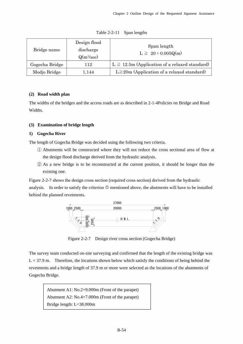
Figure 2-2-7 shows the design cross section (required cross section) derived from the hydraulic
analysis. In order to satisfy the criterion mentioned above, the abutments will have to be installed
behind the planned revetments.
Figure 2-2-7 Design river cross section (Gogecha Bridge)
The survey team conducted on-site surveying and confirmed that the length of the existing bridge was
L = 37.9 m. Therefore, the locations shown below which satisfy the conditions of being behind the
revetments and a bridge length of 37.9 m or more were selected as the locations of the abutments of
Gogecha Bridge.
Abutment A1: No.2+9.000m (Front of the parapet)
Abutment A2: No.4+7.000m (Front of the parapet)
Bridge length: L=38.000m
Bridge name
Design flood
discharge
Q(m3/sec)
Span length
L ≧ 20+0.005Q(m)
Gogecha Bridge 112 L ≧ 12.5m (Application of a relaxed standard)
Modjo Bridge 1,144 L≧20m (Application of a relaxed standard)
H.W.L900
1600 2500
1000 2500 20000 2500 1000
27000
1:1.0 1:1.0
Chapter 2 Outline Design of the Requested Japanese Assistance
B-55
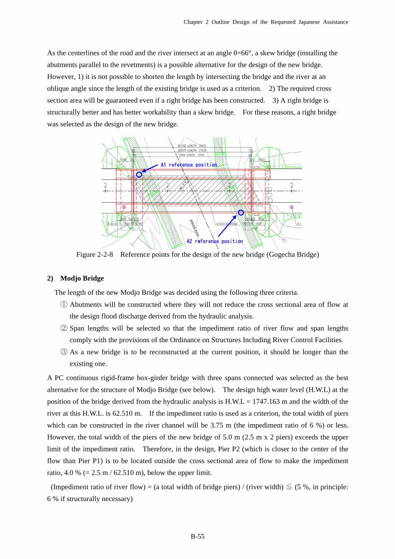
As the centerlines of the road and the river intersect at an angle θ=66°, a skew bridge (installing the
abutments parallel to the revetments) is a possible alternative for the design of the new bridge.
However, 1) it is not possible to shorten the length by intersecting the bridge and the river at an
oblique angle since the length of the existing bridge is used as a criterion. 2) The required cross
section area will be guaranteed even if a right bridge has been constructed. 3) A right bridge is
structurally better and has better workability than a skew bridge. For these reasons, a right bridge
was selected as the design of the new bridge.
Figure 2-2-8 Reference points for the design of the new bridge (Gogecha Bridge)
2) Modjo Bridge
The length of the new Modjo Bridge was decided using the following three criteria.
① Abutments will be constructed where they will not reduce the cross sectional area of flow at
the design flood discharge derived from the hydraulic analysis.
② Span lengths will be selected so that the impediment ratio of river flow and span lengths
comply with the provisions of the Ordinance on Structures Including River Control Facilities.
③ As a new bridge is to be reconstructed at the current position, it should be longer than the
existing one.
A PC continuous rigid-frame box-girder bridge with three spans connected was selected as the best
alternative for the structure of Modjo Bridge (see below). The design high water level (H.W.L) at the
position of the bridge derived from the hydraulic analysis is H.W.L = 1747.163 m and the width of the
river at this H.W.L. is 62.510 m. If the impediment ratio is used as a criterion, the total width of piers
which can be constructed in the river channel will be 3.75 m (the impediment ratio of 6 %) or less.
However, the total width of the piers of the new bridge of 5.0 m (2.5 m x 2 piers) exceeds the upper
limit of the impediment ratio. Therefore, in the design, Pier P2 (which is closer to the center of the
flow than Pier P1) is to be located outside the cross sectional area of flow to make the impediment
ratio, 4.0 % (= 2.5 m / 62.510 m), below the upper limit.
(Impediment ratio of river flow) = (a total width of bridge piers) / (river width) ≦ (5 %, in principle:
6 % if structurally necessary)
A2 reference position
A1 reference position
Chapter 2 Outline Design of the Requested Japanese Assistance
B-56
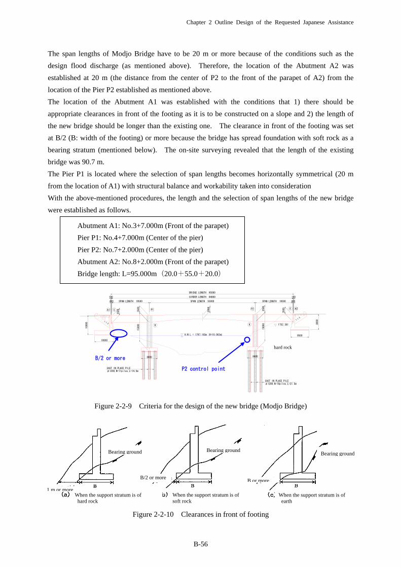
The span lengths of Modjo Bridge have to be 20 m or more because of the conditions such as the
design flood discharge (as mentioned above). Therefore, the location of the Abutment A2 was
established at 20 m (the distance from the center of P2 to the front of the parapet of A2) from the
location of the Pier P2 established as mentioned above.
The location of the Abutment A1 was established with the conditions that 1) there should be
appropriate clearances in front of the footing as it is to be constructed on a slope and 2) the length of
the new bridge should be longer than the existing one. The clearance in front of the footing was set
at B/2 (B: width of the footing) or more because the bridge has spread foundation with soft rock as a
bearing stratum (mentioned below). The on-site surveying revealed that the length of the existing
bridge was 90.7 m.
The Pier P1 is located where the selection of span lengths becomes horizontally symmetrical (20 m
from the location of A1) with structural balance and workability taken into consideration
With the above-mentioned procedures, the length and the selection of span lengths of the new bridge
were established as follows.
Abutment A1: No.3+7.000m (Front of the parapet)
Pier P1: No.4+7.000m (Center of the pier)
Pier P2: No.7+2.000m (Center of the pier)
Abutment A2: No.8+2.000m (Front of the parapet)
Bridge length: L=95.000m(20.0+55.0+20.0)
Figure 2-2-9 Criteria for the design of the new bridge (Modjo Bridge)
Figure 2-2-10 Clearances in front of footing
hard rock
B/2 or more
P2 control point
Bearing ground
When the support stratum is of hard rock
1 m or more
B/2 or more
Bearing groundBearing ground
B or more
When the support stratum is of soft rock
When the support stratum is of earth
CAST IN PLACE PILEφ1200,N=10piles,L=21.5m
CAST IN PLACE PILEφ1200,N=11piles,L=14.5m
1:1.5
1:1.5
A1 E A2E
R
P1
R
P2
1752.381
SPAN LENGTH 19500 SPAN LENGTH 55000 SPAN LENGTH 19500 400
GIRDER LENGTH 94800 100
BRIDGE LENGTH 95000
1000
0
10000
8000
400
100
H.W.L = 1747.163m (H=10.063m)
8400 8400
9500
150
00
150
00
2000
3500
350
0
350
0
350
0
Chapter 2 Outline Design of the Requested Japanese Assistance
B-57
(4) Comparison of bridge structure
1) Gogecha Bridge
As alternative bridge structures, superior ones in terms of structure, workability, economic efficiency
and ease of maintenance were identified using the numbers of spans obtained from the standard span
length defined by the design flood discharge as references and taking the standard bridge structures,
applicable span lengths and the past use in Ethiopia into account. Since the required length and
standard span length of this bridge were 38.0 m and 21.0 m, respectively, the following two alternative
span lengths were considered.
・ Single-span alternative (girder bridge): L = 38.0 m
・ Two-span alternative (girder bridge): L = [email protected] m
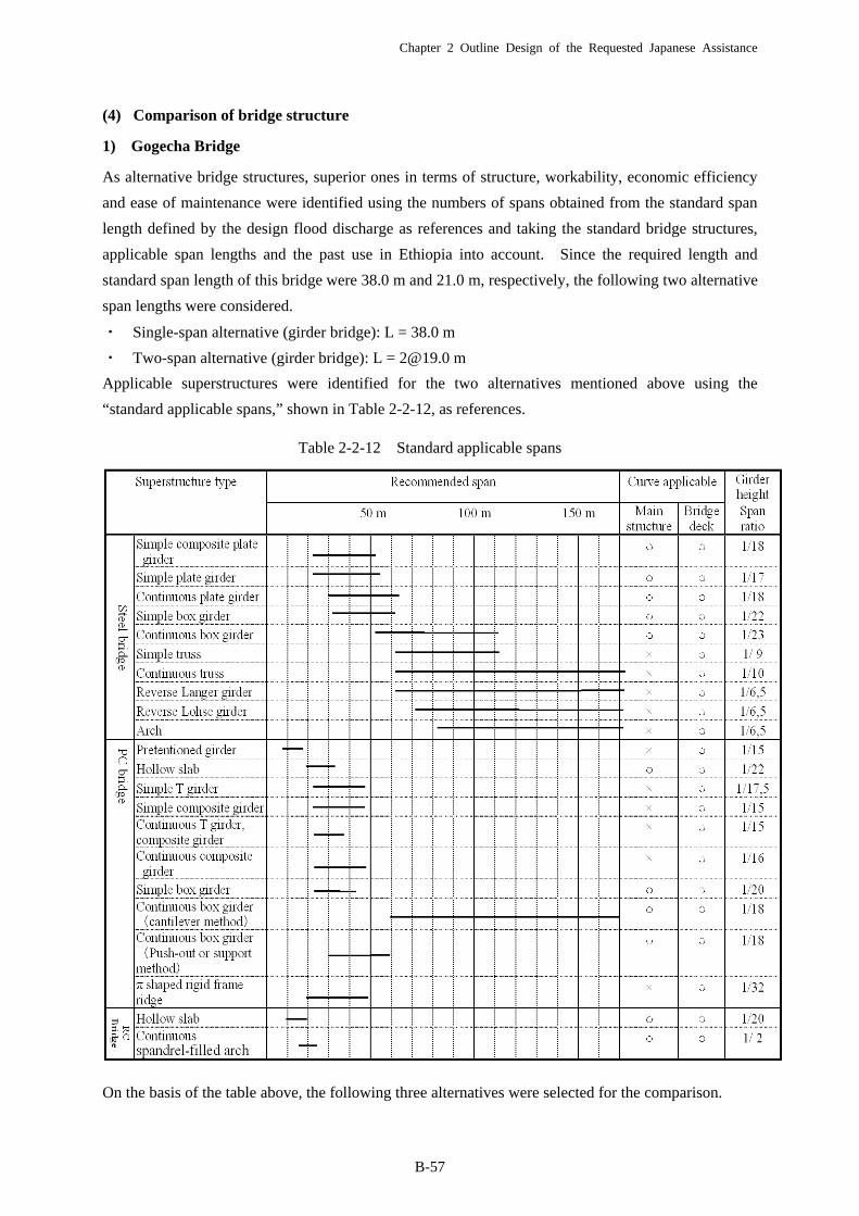
Applicable superstructures were identified for the two alternatives mentioned above using the
“standard applicable spans,” shown in Table 2-2-12, as references.
Table 2-2-12 Standard applicable spans
On the basis of the table above, the following three alternatives were selected for the comparison.
Chapter 2 Outline Design of the Requested Japanese Assistance
B-58
Table 2-2-13 Alternative bridge structures compared (Gogecha Bridge)
Since the comparison of the three alternatives had revealed that the Alternative 1 was the best
alternative, it was selected as the structure of Gogecha Bridge. (See Table 2-2-15)
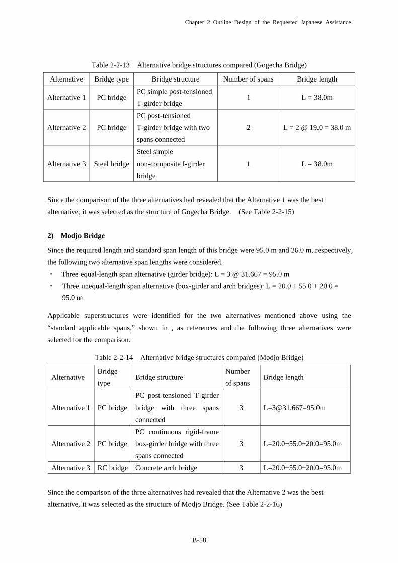
2) Modjo Bridge
Since the required length and standard span length of this bridge were 95.0 m and 26.0 m, respectively,
the following two alternative span lengths were considered.
・ Three equal-length span alternative (girder bridge): L = 3 @ 31.667 = 95.0 m
・ Three unequal-length span alternative (box-girder and arch bridges): L = 20.0 + 55.0 + 20.0 =
95.0 m
Applicable superstructures were identified for the two alternatives mentioned above using the
“standard applicable spans,” shown in , as references and the following three alternatives were
selected for the comparison.
Table 2-2-14 Alternative bridge structures compared (Modjo Bridge)
Since the comparison of the three alternatives had revealed that the Alternative 2 was the best
alternative, it was selected as the structure of Modjo Bridge. (See Table 2-2-16)
Alternative Bridge type Bridge structure Number of spans Bridge length
Alternative 1 PC bridge PC simple post-tensioned
T-girder bridge 1 L = 38.0m
Alternative 2 PC bridge
PC post-tensioned
T-girder bridge with two
spans connected
2 L = 2 @ 19.0 = 38.0 m
Alternative 3 Steel bridge
Steel simple
non-composite I-girder
bridge
1 L = 38.0m
Alternative Bridge
type Bridge structure
Number
of spans Bridge length
Alternative 1 PC bridge
PC post-tensioned T-girder
bridge with three spans
connected
3 [email protected]=95.0m
Alternative 2 PC bridge
PC continuous rigid-frame
box-girder bridge with three
spans connected
3 L=20.0+55.0+20.0=95.0m
Alternative 3 RC bridge Concrete arch bridge 3 L=20.0+55.0+20.0=95.0m
Chapter 2 Outline Design of the Requested Japanese Assistance
B-59
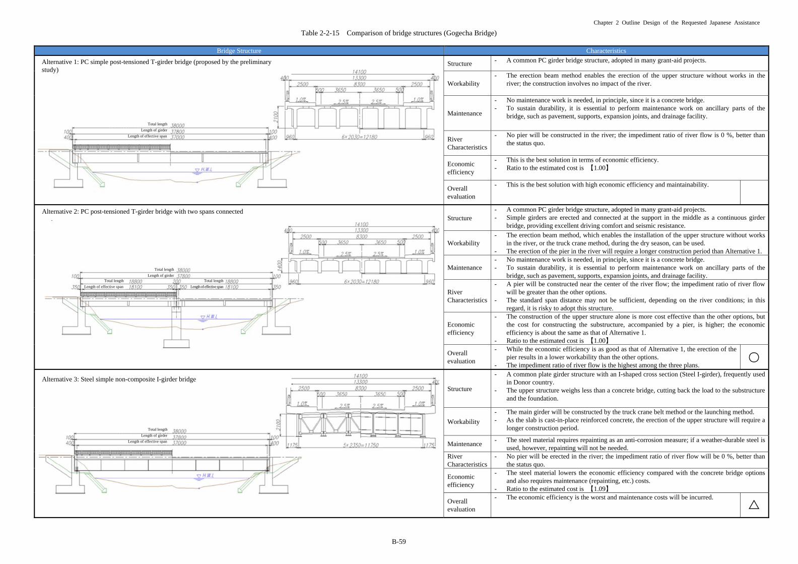
Table 2-2-15 Comparison of bridge structures (Gogecha Bridge)
Bridge Structure Characteristics
Structure - A common PC girder bridge structure, adopted in many grant-aid projects.
Workability - The erection beam method enables the erection of the upper structure without works in the
river; the construction involves no impact of the river.
Maintenance
- No maintenance work is needed, in principle, since it is a concrete bridge. - To sustain durability, it is essential to perform maintenance work on ancillary parts of the
bridge, such as pavement, supports, expansion joints, and drainage facility.
River Characteristics
- No pier will be constructed in the river; the impediment ratio of river flow is 0 %, better than the status quo.
Economic efficiency
- This is the best solution in terms of economic efficiency. - Ratio to the estimated cost is 【1.00】
Overall evaluation
- This is the best solution with high economic efficiency and maintainability.
Structure
- A common PC girder bridge structure, adopted in many grant-aid projects. - Simple girders are erected and connected at the support in the middle as a continuous girder
bridge, providing excellent driving comfort and seismic resistance.
Workability - The erection beam method, which enables the installation of the upper structure without works
in the river, or the truck crane method, during the dry season, can be used. - The erection of the pier in the river will require a longer construction period than Alternative 1.
Maintenance - No maintenance work is needed, in principle, since it is a concrete bridge. - To sustain durability, it is essential to perform maintenance work on ancillary parts of the
bridge, such as pavement, supports, expansion joints, and drainage facility.
River Characteristics
- A pier will be constructed near the center of the river flow; the impediment ratio of river flow will be greater than the other options.
- The standard span distance may not be sufficient, depending on the river conditions; in this regard, it is risky to adopt this structure.
Economic efficiency
- The construction of the upper structure alone is more cost effective than the other options, but the cost for constructing the substructure, accompanied by a pier, is higher; the economic efficiency is about the same as that of Alternative 1.
- Ratio to the estimated cost is 【1.00】
Overall evaluation
- While the economic efficiency is as good as that of Alternative 1, the erection of the pier results in a lower workability than the other options.
- The impediment ratio of river flow is the highest among the three plans.
Structure
- A common plate girder structure with an I-shaped cross section (Steel I-girder), frequently used in Donor country.
- The upper structure weighs less than a concrete bridge, cutting back the load to the substructure and the foundation.
Workability
- The main girder will be constructed by the truck crane belt method or the launching method. - As the slab is cast-in-place reinforced concrete, the erection of the upper structure will require a
longer construction period.
Maintenance - The steel material requires repainting as an anti-corrosion measure; if a weather-durable steel is
used, however, repainting will not be needed. River Characteristics
- No pier will be erected in the river; the impediment ratio of river flow will be 0 %, better than the status quo.
Economic efficiency
- The steel material lowers the economic efficiency compared with the concrete bridge options and also requires maintenance (repainting, etc.) costs.
- Ratio to the estimated cost is 【1.09】
Overall evaluation
- The economic efficiency is the worst and maintenance costs will be incurred.
Total length
Length of girder
Length of effective span
Alternative 1: PC simple post-tensioned T-girder bridge (proposed by the preliminary study)
Total length
Length of girderTotal length
Length of effective span
Total length
Length of effective span
Alternative 2: PC post-tensioned T-girder bridge with two spans connected
Total length
Length of girder
Length of effective span
Alternative 3: Steel simple non-composite I-girder bridge
○
△

Chapter 2 Outline Design of the Requested Japanese Assistance
B-60
Table 2-2-16 Comparison of bridge structures (Modjo Bridge) Bridge Structure Characteristics
Structure
- A common PC girder bridge structure, adopted in many grant-aid projects. - Simple girders are erected and connected at the supports in the middle as a continuous girder
bridge, providing excellent driving comfort and seismic resistance. - The bridge is situated in steep terrains, needing high piers.
Workability - The erection beam method enables the erection of the upper structure without works in the
river; the construction involves no impact of the river. - The high piers will require a longer construction period.
Maintenance - No maintenance work is needed, in principle, since it is a concrete bridge. - To sustain durability, it is essential to perform maintenance work on ancillary parts of the
bridge, such as pavement, supports, expansion joints, and drainage facility.
River Characteristics
- Impact on the river is larger than the other alternatives, since the piers will be erected within the cross-section area of river flow.
- The impediment ratio of river flow to the high water level (HWL) will likely exceed 10%, whereas the standard ratio is below 5 %.
Economic efficiency- This is the best solution in terms of economic efficiency. - Ratio to the estimated cost is 【1.00】
Overall evaluation
- This is the best solution in terms of economic efficiency and maintainability, but due to the river characteristics issues, a hydrological analysis may find this structure infeasible.
- The construction of high piers in the river requires a longer construction period and thus countermeasures against swollen streams will be needed.
Structure
- The PC box-girder structure is suitable for long spans and has been adopted in many grant-aid projects.
- The high piers allow the continuous rigid-frame structure, providing excellent driving comfort, seismic resistance and maintainability.
Workability
- The adoption of the cantilever erection method for the upper structure will involve no impact of the river.
- As the upper structure is cast in place, it will require a longer construction period than the precast method in Alternative1.
Maintenance
- No maintenance work is needed, in principle, since it is a concrete bridge. - To sustain durability, it is essential to perform maintenance work on ancillary parts of the
bridge. The maintenance work for this structure is, however, less labor-consuming than Alternative 1, which involves many supports, as the piers will have a rigid connection structure instead of supports.
River Characteristics - Minimum impact on the river since the piers can be erected avoiding the cross section of flow.
Economic efficiency- This alternative ranks in the middle in terms of economic efficiency. - Ratio to the estimated cost is 【1.05】
Overall evaluation - Although the economic efficiency is lower than that of Alternative1, the river
cross-section impediment issue is cleared and the structure, workability and maintainability are all excellent; thus, this is the best solution on the whole.
Structure
- The main cross-sectional force is compression. This is a rational structure which effectively utilizes the compression-resistance of concrete.
- Often used in valleys and other steep terrains.
Workability - The adoption of the pylon method (cantilever erection) for arch ribs enables the construction
without impact of the river. - The longest construction period among the three plans.
Maintenance - No maintenance work is needed, in principle, since it is a concrete bridge. - To sustain durability, it is essential to perform maintenance work on ancillary parts of the
bridge, such as pavement, supports, expansion joints, and drainage facility. River Characteristics - No pier will be erected in the river; the construction will involve no impact on the river.
Economic efficiency- Lower than the other options. - Ratio to the estimated cost is 【1.65】
Overall evaluation
- Though the economic efficiency is poor, the impact of swollen river on the construction schedule is minimal as it involves no works in the river.
- Because there is no impact on the river, this is a favorable alternative as well as Alternative 2, in terms of river characteristics.
- The structure is suitable for steep terrains in terms of landscape.
Total length
Length of girder
Length of effective span Length of girder
Length of effective span
Length of girder
Length of effective span
Alternative 1: PC post-tensioned T-girder bridge with three spans connected (proposed by the preliminary study)
Total length
Length of girder
Length of effective span Length of effective span Length of effective span
Alternative 2: PC continuous rigid-frame box-girder bridge with three spans connected (alternative proposal)
Total length
Length of girder
Length of effective span of arch section
Arch rise
Alternative 3: Concrete arch bridge
△
○
Chapter 2 Outline Design of the Requested Japanese Assistance
B-61
(5) Examination on structures of substructure and foundation works
1) Gogecha Bridge
i) Selection of bearing stratum
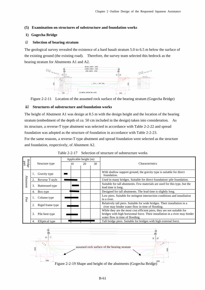
The geological survey revealed the existence of a hard basalt stratum 5.0 to 6.5 m below the surface of
the existing ground (the existing road). Therefore, the survey team selected this bedrock as the
bearing stratum for Abutments A1 and A2.
Figure 2-2-11 Location of the assumed rock surface of the bearing stratum (Gogecha Bridge)
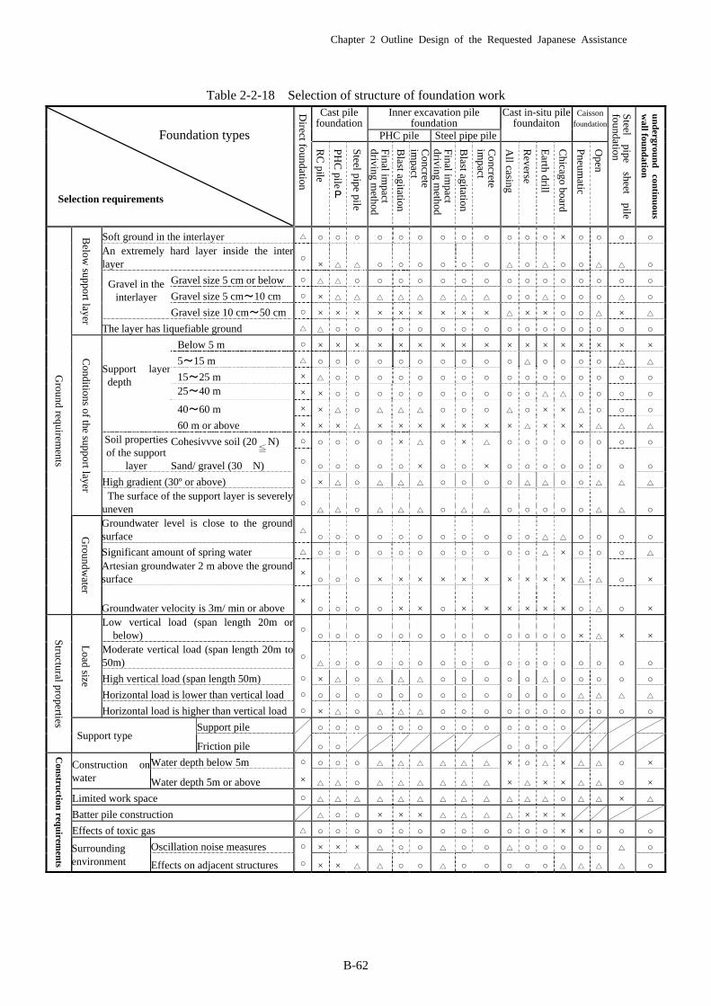
ii) Structures of substructure and foundation works
The height of Abutment A1 was design at 8.5 m with the design height and the location of the bearing
stratum (embedment of the depth of ca. 50 cm included in the design) taken into consideration. As
its structure, a reverse-T type abutment was selected in accordance with Table 2-2-22 and spread
foundation was adopted as the structure of foundation in accordance with Table 2-2-23.
For the same reasons, a reverse-T type abutment and spread foundation were selected as the structure
and foundation, respectively, of Abutment A2.
Table 2-2-17 Selection of structure of substructure works
Figure 2-2-19 Shape and height of the abutments (Gogecha Bridge)
Bridge part Structure type
Applicable height (m)
Characteristics 10 20 30
Abutm
ent
1. Gravity type With shallow support ground, the gravity type is suitable for direct
foundation.
2. Reverse T-style Used in many bridges. Suitable for direct foundation/ pile foundation.
3. Buttressed type Suitable for tall abutments. Few materials are used for this type, but the
lead time is long.
4. Box type Designed for tall abutments. The lead time is slightly long.
Pier
1. Column type Low piers. Suitable for stringent intersection conditions and installation
in a river.
2. Rigid frame type Relatively tall piers. Suitable for wide bridges. Their installation in a river may hinder water flow in time of flooding.
3. Pile bent type While they are the most cost efficient piers, they are not suitable for
bridges with high horizontal force. Their installation in a river may hinder water flow in time of flooding.
4. Elliptical type Tall bridge piers. Suitable for bridges with high external force.
1:1.5
F
400
100
A1
7000
8500
1:1.5
8500
A2
400
100
M
6500
assumed rock surface of the bearing stratum
7000
8500
6500
8500
A2F
SPAN LENGTH 37000 400400
GIRDER LENGTH 37800 100100
BRIDGE LENGTH 38000
A1 M
H.W.L = 1957.522m
1:1.5 1:1.5
ESTIMATED SUPPORTING LAYER
0 10 20 30 40 50N-value
B-Go-01 GL=1961.76m,dep=9.5m
0 10 20 30 40 50N-value
B-Go-02
GL=1961
.67m,dep
=7.4m
60 60
Chapter 2 Outline Design of the Requested Japanese Assistance
B-62
Table 2-2-18 Selection of structure of foundation work
Foundation types
Selection requirements
Direct foundation
Cast pile foundation
Inner excavation pile foundation
Cast in-situ pile foundaiton
Caisson foundation
Steel
pipe sheet
pile foundation
un
dergrou
nd
con
tinu
ous
wall fou
nd
ation
PHC pile Steel pipe pile
RC
pile
PH
C pile
P
Steel pipe pile
Final im
pact driving m
ethod
Blast agitation
Concrete
impact
Final im
pact driving m
ethod
Blast agitation
Concrete
impact
All casing
Reverse
Earth drill
Chicago board
Pneum
atic
Open
Ground requirem
ents
Below
support layer
Soft ground in the interlayer △ ○ ○ ○ ○ ○ ○ ○ ○ ○ ○ ○ ○ × ○ ○ ○ ○
An extremely hard layer inside the interlayer
○× △ △ ○ ○ ○ ○ ○ ○ △ ○ △ ○ ○ △ △ ○
Gravel in the
interlayer
Gravel size 5 cm or below ○ △ △ ○ ○ ○ ○ ○ ○ ○ ○ ○ ○ ○ ○ ○ ○ ○
Gravel size 5 cm~10 cm ○ × △ △ △ △ △ △ △ △ ○ ○ △ ○ ○ ○ △ ○
Gravel size 10 cm~50 cm ○ × × × × × × × × × △ × × ○ ○ △ × △
The layer has liquefiable ground △ △ ○ ○ ○ ○ ○ ○ ○ ○ ○ ○ ○ ○ ○ ○ ○ ○
Conditions of the support layer
Support layer depth
Below 5 m ○ × × × × × × × × × × × × × × × × ×
5~15 m △ ○ ○ ○ ○ ○ ○ ○ ○ ○ ○ △ ○ ○ ○ ○ △ △
15~25 m × △ ○ ○ ○ ○ ○ ○ ○ ○ ○ ○ ○ ○ ○ ○ ○ ○
25~40 m × × ○ ○ ○ ○ ○ ○ ○ ○ ○ ○ △ △ ○ ○ ○ ○
40~60 m × × △ ○ △ △ △ ○ ○ ○ △ ○ × × △ ○ ○ ○
60 m or above × × × △ × × × × × × × △ × × × △ △ △
Soil properties of the support
layer
Cohesivvve soil (20 N) ○ ○ ○ ○ ○ × △ ○ × △ ○ ○ ○ ○ ○ ○ ○ ○
Sand/ gravel (30 N) ○ ○ ○ ○ ○ ○ × ○ ○ × ○ ○ ○ ○ ○ ○ ○ ○
High gradient (30º or above) ○ × △ ○ △ △ △ ○ ○ ○ ○ △ △ ○ ○ △ △ △
The surface of the support layer is severelyuneven
○△ △ ○ △ △ △ ○ △ △ ○ ○ ○ ○ ○ △ △ ○
Groundw
ater
Groundwater level is close to the groundsurface
△○ ○ ○ ○ ○ ○ ○ ○ ○ ○ ○ △ △ ○ ○ ○ ○
Significant amount of spring water △ ○ ○ ○ ○ ○ ○ ○ ○ ○ ○ ○ △ × ○ ○ ○ △
Artesian groundwater 2 m above the groundsurface
×○ ○ ○ × × × × × × × × × × △ △ ○ ×
Groundwater velocity is 3m/ min or above ×
○ ○ ○ ○ × × ○ × × × × × × ○ △ ○ ×
Structural properties
Load size
Low vertical load (span length 20m orbelow)
○○ ○ ○ ○ ○ ○ ○ ○ ○ ○ ○ ○ ○ × △ × ×
Moderate vertical load (span length 20m to50m)
○△ ○ ○ ○ ○ ○ ○ ○ ○ ○ ○ ○ ○ ○ ○ ○ ○
High vertical load (span length 50m) ○ × △ ○ △ △ △ ○ ○ ○ ○ ○ △ ○ ○ ○ ○ ○
Horizontal load is lower than vertical load ○ ○ ○ ○ ○ ○ ○ ○ ○ ○ ○ ○ ○ ○ △ △ △ △
Horizontal load is higher than vertical load ○ × △ ○ △ △ △ ○ ○ ○ ○ ○ ○ ○ ○ ○ ○ ○
Support type Support pile ○ ○ ○ ○ ○ ○ ○ ○ ○ ○ ○ ○ ○
Friction pile ○ ○ ○ ○ ○
Con
struction
requ
iremen
ts
Construction on water
Water depth below 5m ○ ○ ○ ○ △ △ △ △ △ △ × ○ △ × △ △ ○ ×
Water depth 5m or above × △ △ ○ △ △ △ △ △ △ × △ × × △ △ ○ ×
Limited work space ○ △ △ △ △ △ △ △ △ △ △ △ △ ○ △ △ × △
Batter pile construction △ ○ ○ × × × △ △ △ △ × × ×
Effects of toxic gas △ ○ ○ ○ ○ ○ ○ ○ ○ ○ ○ ○ ○ × × ○ ○ ○
Surrounding environment
Oscillation noise measures ○ × × × △ ○ ○ △ ○ ○ △ ○ ○ ○ ○ ○ △ ○
Effects on adjacent structures ○ × × △ △ ○ ○ △ ○ ○ ○ ○ ○ △ △ △ △ ○
≦
Chapter 2 Outline Design of the Requested Japanese Assistance
B-63
2) Modjo Bridge
i) Selection of bearing strata
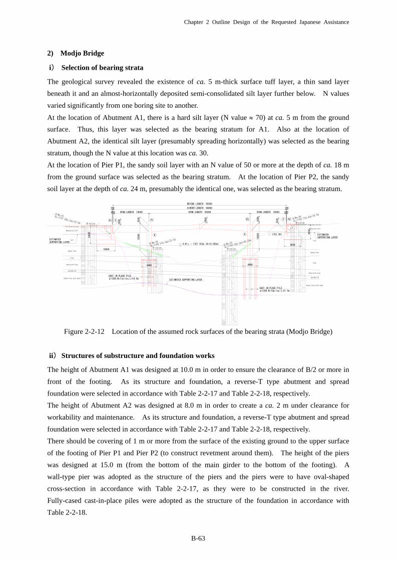
The geological survey revealed the existence of ca. 5 m-thick surface tuff layer, a thin sand layer
beneath it and an almost-horizontally deposited semi-consolidated silt layer further below. N values
varied significantly from one boring site to another.
At the location of Abutment A1, there is a hard silt layer (N value 70) at ca. 5 m from the ground
surface. Thus, this layer was selected as the bearing stratum for A1. Also at the location of
Abutment A2, the identical silt layer (presumably spreading horizontally) was selected as the bearing
stratum, though the N value at this location was ca. 30.
At the location of Pier P1, the sandy soil layer with an N value of 50 or more at the depth of ca. 18 m
from the ground surface was selected as the bearing stratum. At the location of Pier P2, the sandy
soil layer at the depth of ca. 24 m, presumably the identical one, was selected as the bearing stratum.
Figure 2-2-12 Location of the assumed rock surfaces of the bearing strata (Modjo Bridge)
ii) Structures of substructure and foundation works
The height of Abutment A1 was designed at 10.0 m in order to ensure the clearance of B/2 or more in
front of the footing. As its structure and foundation, a reverse-T type abutment and spread
foundation were selected in accordance with Table 2-2-17 and Table 2-2-18, respectively.
The height of Abutment A2 was designed at 8.0 m in order to create a ca. 2 m under clearance for
workability and maintenance. As its structure and foundation, a reverse-T type abutment and spread
foundation were selected in accordance with Table 2-2-17 and Table 2-2-18, respectively.
There should be covering of 1 m or more from the surface of the existing ground to the upper surface
of the footing of Pier P1 and Pier P2 (to construct revetment around them). The height of the piers
was designed at 15.0 m (from the bottom of the main girder to the bottom of the footing). A
wall-type pier was adopted as the structure of the piers and the piers were to have oval-shaped
cross-section in accordance with Table 2-2-17, as they were to be constructed in the river.
Fully-cased cast-in-place piles were adopted as the structure of the foundation in accordance with
Table 2-2-18.
SUPPORTING LAYER
ESTIMATED SUPPORTING LAYER
ESTIMATED SUPPORTING LAYER
0 10 20 30 40 50N-value
B-Mo-01 GL=1757.69m,dep=32.0m60
0 10 20 30 40 50N-value
B-Mo-02
GL=1744
.51m,dep
=23.5m
600 10 20 30 40 50N-value
B-Mo-03
GL=1743
.93m,dep
=40.25m
60
0 10 20 30 40 50N-value
B-Mo-04
GL=1758
.13m,dep
=36.5m
60
CAST IN PLACE PILEφ1200,N=10piles,L=21.5m
CAST IN PLACE PILEφ1200,N=11piles,L=14.5m
1:1.5
1:1.5
A1 E A2E
R
P1
R
P2
Silty Gravel with Sand
Weathered Tuff
Tuff
Sandy Clay
Clay
Sand with Clay
Ignimbrite
Sandy Clay with Sand
Silty Gravel with Sand
Weathered Tuff
Tuff
Sandy Clay
Clay
Sand with Clay
Ignimbrite
Sandy Clay with Sand
1752.381
ESTIMATED
SPAN LENGTH 19500 SPAN LENGTH 55000 SPAN LENGTH 19500 400
GIRDER LENGTH 94800 100
BRIDGE LENGTH 95000
10000
10000
8000
400
100
H.W.L = 1747.163m (H=10.063m)
8400 8400
9500
15000
15000
2000
3500
3500
3500
3500

Chapter 2 Outline Design of the Requested Japanese Assistance
B-64
Figure 2-2-13 Shape and height of the substructure works (1/2) (Modjo Bridge)
Figure 2-2-14 Shape and height of the substructure works (2/2) (Modjo Bridge)
SUPPORTING LAYER
CAST IN PLACE PILEφ1200,N=11piles,L=14.5m
1:1.5
A1 E
R
P1
Silty Gravel with Sand
Weathered Tuff
Tuff
Sandy Clay
Clay
Sand with Clay
Ignimbrite
Sandy Clay with Sand
ESTIMATED
SPAN LENGTH 19500
10000
10000
400
100
8400
15000
3500
3500
ESTIMATED SUPPORTING LAYER
CAST IN PLACE PILEφ1200,N=10piles,L=21.5m
1:1.5
A2E
R
P2
Silty Gravel with Sand
Weathered Tuff
Tuff
Sandy Clay
Clay
Sand with Clay
Ignimbrite
Sandy Clay with Sand
1752.381
SPAN LENGTH 19500 400
100
8000
8400
9500
15000
3500
3500

Chapter 2 Outline Design of the Requested Japanese Assistance
B-65
(6) Examination on revetment and bed protection works
While revetment work will be required for the construction of Gogecha and Modjo Bridges because
substructure works will be constructed in the river channels, it will not be required for the construction
of Awash Bridge because substructure works will not be constructed in the river channel.
1) Gogecha Bridge
While the existing Gogecha Bridge has two spans, the new bridge will have one span. Because of
this change in the design, revetment around the abutment will be included in the design. Since the
flow velocity at the design flood discharge derived from non-uniform flow calculation is ca. 3 m/s, the
design will include (1:1) mortar masonry revetments on the minimum required areas upstream and
downstream of the abutments to protect the embankment around them. The slopes of the revetments
will be constructed in the river channel after examining its current configuration so as not to change
the level of flood water significantly after the construction of the new bridge.
2) Modjo Bridge
The design of the new Modjo Bridge includes construction of two piers in the river channel, which
will require revetment to protect the areas of river banks below HWL to be excavated for the
foundation works of the piers. Since the flow velocity at the design flood discharge derived from
non-uniform flow calculation is ca. 3 m/s, mortar masonry revetment will be adopted in the design.
The revetments and the existing river banks will be connected in such a way to ensure smooth flow of
flood water along the river banks upstream and downstream of the revetments.
(7) Examination on access roads
1) Examination on compositions of pavement
i) Design life
The design life of the pavement of the road concerned shall be 20 years as that of the trunk road shown
in Table 2-2-19.
Table 2-2-19 Design life of pavement
ii) Design traffic volume
a) Gogecha Bridge
As described in 2-1-3(3), Future Traffic Volume Estimates, A.A.D.T. traffic volume on Gogecha
Bridge 20 years from now is estimated at 9,431 vehicles/day. The table below shows the estimates of
the cumulative traffic volume (vehicle · one-way) during the design life.
Design Period (Years)
20
20
15
10
page2-3
Road Classification
Trunk Road
Link Road
Main Access Road
Other Roads
Chapter 2 Outline Design of the Requested Japanese Assistance
B-66
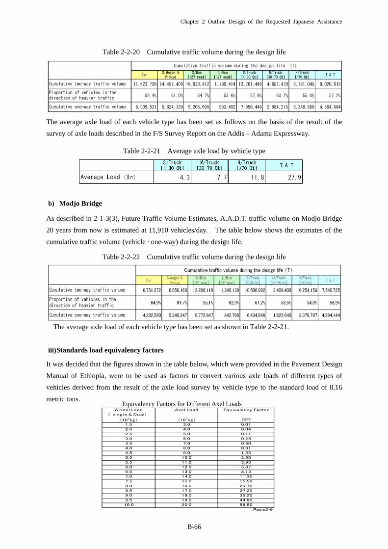
Table 2-2-20 Cumulative traffic volume during the design life
The average axle load of each vehicle type has been set as follows on the basis of the result of the
survey of axle loads described in the F/S Survey Report on the Addis – Adama Expressway.
Table 2-2-21 Average axle load by vehicle type
b) Modjo Bridge
As described in 2-1-3(3), Future Traffic Volume Estimates, A.A.D.T. traffic volume on Modjo Bridge
20 years from now is estimated at 11,910 vehicles/day. The table below shows the estimates of the
cumulative traffic volume (vehicle · one-way) during the design life.
Table 2-2-22 Cumulative traffic volume during the design life
The average axle load of each vehicle type has been set as shown in Table 2-2-21.
iii) Standards load equivalency factors
It was decided that the figures shown in the table below, which were provided in the Pavement Design
Manual of Ethiopia, were to be used as factors to convert various axle loads of different types of
vehicles derived from the result of the axle load survey by vehicle type to the standard load of 8.16
metric tons.
W heel Load Axel Load Equivalency Factor
( sing le & Dual)
(103kg ) (103kg ) (EF)
1.5 3.0 0.01
2.0 4.0 0.04
2.5 5.0 0.11
3.0 6.0 0.25
3.5 7.0 0.50
4.0 8.0 0.91
4.5 9.0 1.55
5.0 10.0 2.50
5.5 11.0 3.93
6.0 12.0 5.67
6.5 13.0 8.13
7.0 14.0 11.30
7.5 15.0 15.50
8.0 16.0 20.70
8.5 17.0 27.20
9.0 18.0 35.20
9.5 19.0 44.90
10.0 20.0 56.50
Page2-9
Equivalency Factors for Different Axel Loads

Chapter 2 Outline Design of the Requested Japanese Assistance
B-67
a) Gogecha Bridge
The total equivalent standard axle loads (ESAs) at Gogecha Bridge were estimated from the
cumulative traffic volume during the design life as shown in the table below.
The figure of the one-way ESAs is to be reduced in accordance with the number of lanes in each
direction. As the section of the road surveyed has one lane in each direction, the 100 % figure will be
used in the pavement design.
Thus, the design ESAs of 1.6 are obtained from the equation below.
1.6 * 100% = 1.6
Therefore, the traffic class T4 will apply to the pavement design of the access road to Gogecha
Bridge.
b) Modjo Bridge
The total ESAs at Modjo Bridge were estimated from the cumulative traffic volume during the design
life as shown in the table below.
Traffic classes Rang e (106 ESAs)T1 <0.3
T2 0.3 - 0.7
T3 0.7 - 1.5
T4 1.5 - 3.0
T5 3.0 - 6.0
T6 6.0 - 10
T7 10 - 17
T8 17 - 30
Page2-10
Gogecha Bridge
Typ e of Veh icle Equ ivalency Factor 累計交通量 106 ESAs
Car 0 24,938,754 0.0
Bus 0.14 953,492 0.0
Truck 6.67 16,284,246 1.1
Truck-Trailer 11.47 4,584,564 0.5
Total ESAs 1.6
交通量調査の車種分類を下記の通り 統合する。
Car
Bus
Truck
Truck-Trailer T & T
L/Bus [> 27 seat]
Car , S.W ag on & Pickup , S/Bus [< 27 seat]
S/Truck [< 30 Qt] , M/Truck[30-70 Qt] , H/Truck [> 70 Qt]
Num ber of Lanes
in each d irection
Percent of ESAs
in d esig n Lane1 100
2 80 - 100
3 60 - 80
Page2-10
一方向1車線であるこ と から 100% ESAsを設計値と し て使用する。
Modjo Bridge
Type of Veh icle Equ ivalency Factor 累計交通量 106 ESAs
Car 0 16,495,674 0.0
Bus 0.14 842,768 0.0
Truck 6.67 11,634,282 0.8
Truck-Trailer 11.47 4,294,144 0.5
Total ESAs 1.3
交通量調査の車種分類を下記の通り 統合する。
Car
Bus
Truck
Truck-Trailer T & T
L/Bus [> 27 seat]
Car , S.W agon & Pickup , S/Bus [< 27 seat]
S/Truck [< 30 Qt] , M/Truck[30-70 Qt] , H/Truck [> 70 Qt]
Chapter 2 Outline Design of the Requested Japanese Assistance
B-68
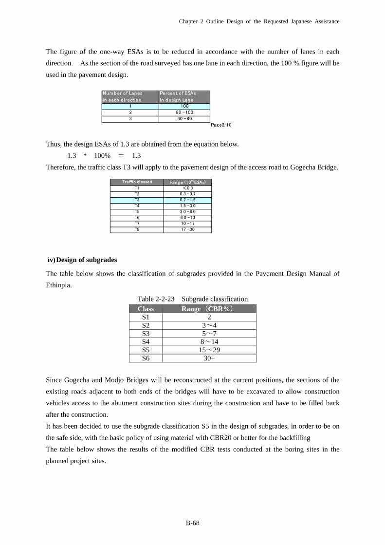
The figure of the one-way ESAs is to be reduced in accordance with the number of lanes in each
direction. As the section of the road surveyed has one lane in each direction, the 100 % figure will be
used in the pavement design.
Thus, the design ESAs of 1.3 are obtained from the equation below.
1.3 * 100% = 1.3
Therefore, the traffic class T3 will apply to the pavement design of the access road to Gogecha Bridge.
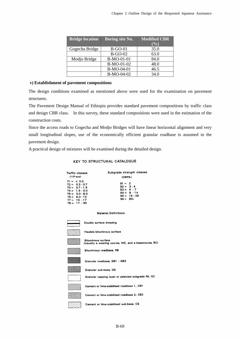
iv) Design of subgrades
The table below shows the classification of subgrades provided in the Pavement Design Manual of
Ethiopia.
Table 2-2-23 Subgrade classification
Since Gogecha and Modjo Bridges will be reconstructed at the current positions, the sections of the
existing roads adjacent to both ends of the bridges will have to be excavated to allow construction
vehicles access to the abutment construction sites during the construction and have to be filled back
after the construction.
It has been decided to use the subgrade classification S5 in the design of subgrades, in order to be on
the safe side, with the basic policy of using material with CBR20 or better for the backfilling
The table below shows the results of the modified CBR tests conducted at the boring sites in the
planned project sites.
Class Range(CBR%)S1 2S2 3~4S3 5~7S4 8~14S5 15~29S6 30+
Traffic classes Rang e (106 ESAs)T1 <0.3
T2 0.3 - 0.7
T3 0.7 - 1.5
T4 1.5 - 3.0
T5 3.0 - 6.0
T6 6.0 - 10
T7 10 - 17
T8 17 - 30
Num b er of Lanes
in each d irection
Percen t of ESAs
in d esig n Lane1 100
2 80 - 100
3 60 - 80
Page2-10
一方向1車線であるこ と から 100% ESAsを設計値と し て使用する。
Chapter 2 Outline Design of the Requested Japanese Assistance
B-69
v) Establishment of pavement compositions
The design conditions examined as mentioned above were used for the examination on pavement
structures.
The Pavement Design Manual of Ethiopia provides standard pavement compositions by traffic class
and design CBR class. In this survey, these standard compositions were used in the estimation of the
construction costs.
Since the access roads to Gogecha and Modjo Bridges will have linear horizontal alignment and very
small longitudinal slopes, use of the economically efficient granular roadbase is assumed in the
pavement design.
A practical design of mixtures will be examined during the detailed design.
Bridge location Boring site No. Modified CBR (%)
Gogecha Bridge B-GO-01 35.0 B-GO-02 63.0
Modjo Bridge B-MO-01-01 84.0 B-MO-01-02 48.0 B-MO-04-01 46.5 B-MO-04-02 34.0
Chapter 2 Outline Design of the Requested Japanese Assistance
B-70
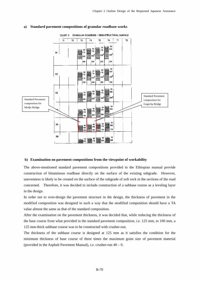
a) Standard pavement compositions of granular roadbase works
b) Examination on pavement compositions from the viewpoint of workability
The above-mentioned standard pavement compositions provided in the Ethiopian manual provide
construction of bituminous roadbase directly on the surface of the existing subgrade. However,
unevenness is likely to be created on the surface of the subgrade of soft rock in the sections of the road
concerned. Therefore, it was decided to include construction of a subbase course as a leveling layer
in the design.
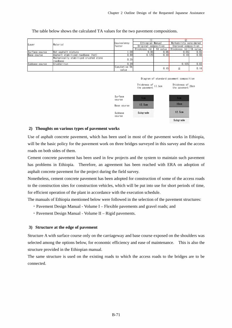
In order not to over-design the pavement structure in the design, the thickness of pavement in the
modified composition was designed in such a way that the modified composition should have a TA
value almost the same as that of the standard composition.
After the examination on the pavement thickness, it was decided that, while reducing the thickness of
the base course from what provided in the standard pavement composition, i.e. 125 mm, to 100 mm, a
125 mm-thick subbase course was to be constructed with crusher-run.
The thickness of the subbase course is designed at 125 mm as it satisfies the condition for the
minimum thickness of base course of three times the maximum grain size of pavement material
(provided in the Asphalt Pavement Manual), i.e. crusher-run 40 – 0.
Standard Pavement
composition for
Modjo Bridge
Standard Pavement
composition for
Gogecha Bridge
Chapter 2 Outline Design of the Requested Japanese Assistance
B-71
The table below shows the calculated TA values for the two pavement compositions.
2) Thoughts on various types of pavement works
Use of asphalt concrete pavement, which has been used in most of the pavement works in Ethiopia,
will be the basic policy for the pavement work on three bridges surveyed in this survey and the access
roads on both sides of them.
Cement concrete pavement has been used in few projects and the system to maintain such pavement
has problems in Ethiopia. Therefore, an agreement has been reached with ERA on adoption of
asphalt concrete pavement for the project during the field survey.
Nonetheless, cement concrete pavement has been adopted for construction of some of the access roads
to the construction sites for construction vehicles, which will be put into use for short periods of time,
for efficient operation of the plant in accordance with the execution schedule.
The manuals of Ethiopia mentioned below were followed in the selection of the pavement structures:
・Pavement Design Manual - Volume I – Flexible pavements and gravel roads; and
・Pavement Design Manual - Volume II – Rigid pavements.
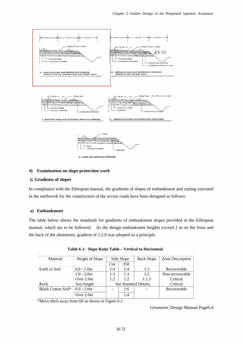
3) Structure at the edge of pavement
Structure A with surface course only on the carriageway and base course exposed on the shoulders was
selected among the options below, for economic efficiency and ease of maintenance. This is also the
structure provided in the Ethiopian manual.
The same structure is used on the existing roads to which the access roads to the bridges are to be
connected.
Chapter 2 Outline Design of the Requested Japanese Assistance
B-72
4) Examination on slope protection work
i) Gradients of slopes
In compliance with the Ethiopian manual, the gradients of slopes of embankment and cutting executed
in the earthwork for the construction of the access roads have been designed as follows:
a) Embankment
The table below shows the standards for gradients of embankment slopes provided in the Ethiopian
manual, which are to be followed. As the design embankment heights exceed 2 m on the front and
the back of the abutments, gradient of 1:2.0 was adopted as a principle.
Geometric Design Manual Page6-4
Table 6-1: Slope Ratio Table – Vertical to Horizontal
Side SlopeMaterial Height of SlopeCut Fill
Back Slope Zone Description
0.0 - 1.0m 1:4 1:4 1:3 Recoverable1.0 - 2.0m 1:3 1:3 1:2 Non-recoverable
Earth or Soil
Over 2.0m 1:2 1:2 1:1.5 CriticalRock Any height See Standard Details Critical
0.0 - 2.0m 1:6Black Cotton Soil*
Over 2.0m
-
1:4
- Recoverable
*Move ditch away from fill as shown in Figure 6-2

Chapter 2 Outline Design of the Requested Japanese Assistance
B-73
b) Cutting
A gradient of 1:1.0 for a back slope shown in the table below will be used as the standard for the
gradient of slope of cutting.
ii) Slope drainage work
A good drainage plan will be required for maintenance of the stability of the slopes in future.
Installation of appropriate drainage structures will be required in particular at the sections on both
sides of Awash Bridge where a large-scale cutting is to be implemented.
Drainage facilities shall be constructed on the top the slopes in order to prevent drainage from the
surrounding area from flowing down the slopes and at the bottom of the slope in order to prevent
rainwater fallen on the slopes from flowing onto the road surface.
With a principle of following the drainage structures provided in the Ethiopian manual, the basic
structures shown below were included in the design
Drainage on the top of a slope Drainage at the bottom of a slope
Chapter 2 Outline Design of the Requested Japanese Assistance
B-74
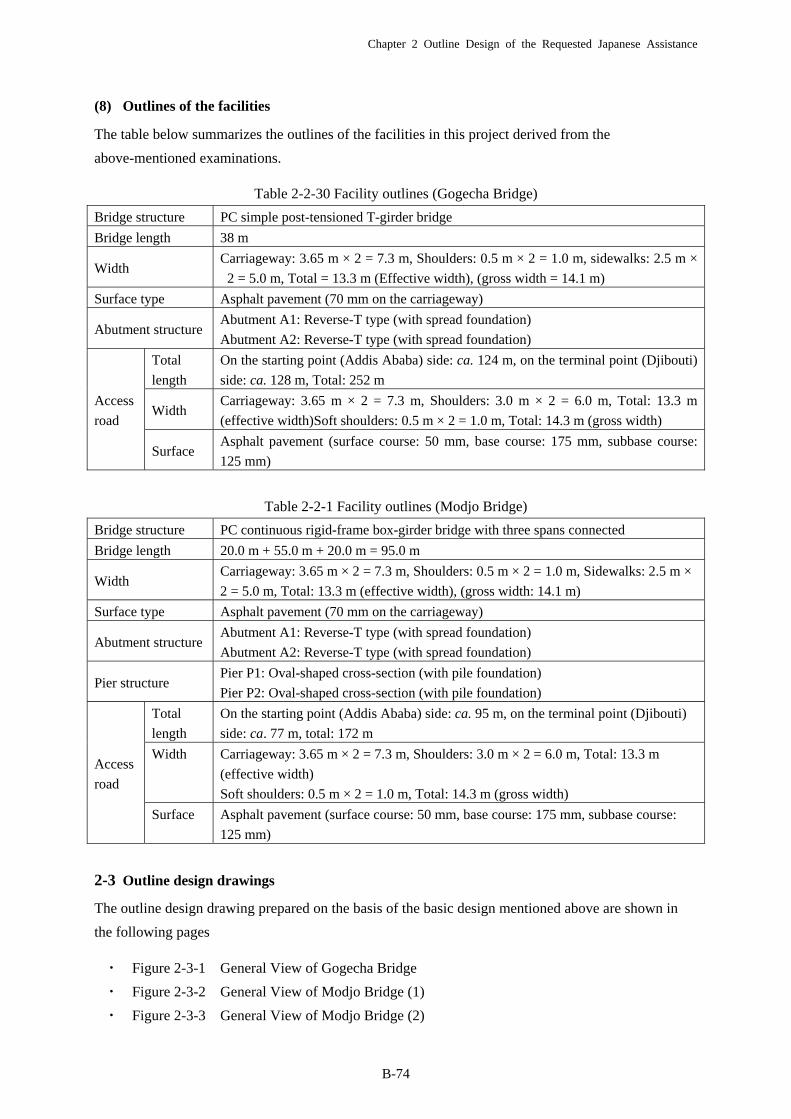
(8) Outlines of the facilities
The table below summarizes the outlines of the facilities in this project derived from the
above-mentioned examinations.
Table 2-2-30 Facility outlines (Gogecha Bridge)
Bridge structure PC simple post-tensioned T-girder bridge
Bridge length 38 m
Width Carriageway: 3.65 m × 2 = 7.3 m, Shoulders: 0.5 m × 2 = 1.0 m, sidewalks: 2.5 m ×
2 = 5.0 m, Total = 13.3 m (Effective width), (gross width = 14.1 m)
Surface type Asphalt pavement (70 mm on the carriageway)
Abutment structure Abutment A1: Reverse-T type (with spread foundation)
Abutment A2: Reverse-T type (with spread foundation)
Access
road
Total
length
On the starting point (Addis Ababa) side: ca. 124 m, on the terminal point (Djibouti)
side: ca. 128 m, Total: 252 m
Width Carriageway: 3.65 m × 2 = 7.3 m, Shoulders: 3.0 m × 2 = 6.0 m, Total: 13.3 m
(effective width)Soft shoulders: 0.5 m × 2 = 1.0 m, Total: 14.3 m (gross width)
Surface Asphalt pavement (surface course: 50 mm, base course: 175 mm, subbase course:
125 mm)
Table 2-2-1 Facility outlines (Modjo Bridge)
Bridge structure PC continuous rigid-frame box-girder bridge with three spans connected
Bridge length 20.0 m + 55.0 m + 20.0 m = 95.0 m
Width Carriageway: 3.65 m × 2 = 7.3 m, Shoulders: 0.5 m × 2 = 1.0 m, Sidewalks: 2.5 m ×
2 = 5.0 m, Total: 13.3 m (effective width), (gross width: 14.1 m)
Surface type Asphalt pavement (70 mm on the carriageway)
Abutment structure Abutment A1: Reverse-T type (with spread foundation)
Abutment A2: Reverse-T type (with spread foundation)
Pier structure Pier P1: Oval-shaped cross-section (with pile foundation)
Pier P2: Oval-shaped cross-section (with pile foundation)
Access
road
Total
length
On the starting point (Addis Ababa) side: ca. 95 m, on the terminal point (Djibouti)
side: ca. 77 m, total: 172 m
Width Carriageway: 3.65 m × 2 = 7.3 m, Shoulders: 3.0 m × 2 = 6.0 m, Total: 13.3 m
(effective width)
Soft shoulders: 0.5 m × 2 = 1.0 m, Total: 14.3 m (gross width)
Surface Asphalt pavement (surface course: 50 mm, base course: 175 mm, subbase course:
125 mm)
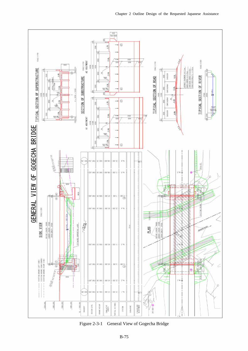
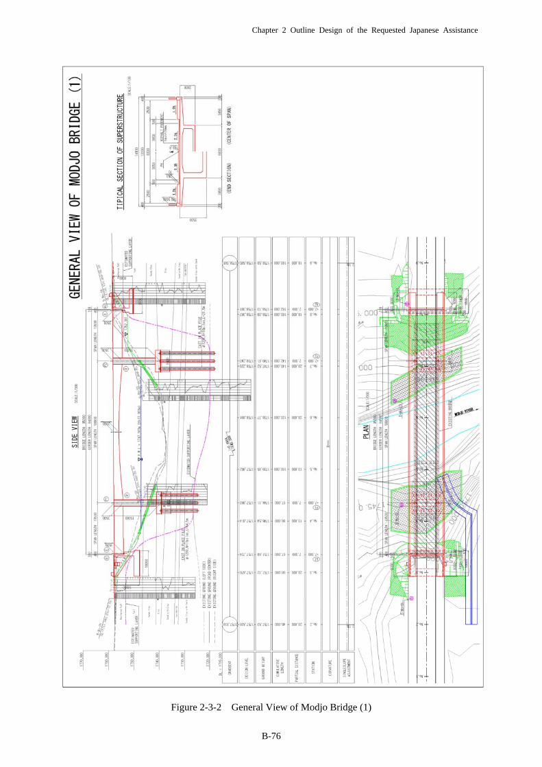
2-3 Outline design drawings
The outline design drawing prepared on the basis of the basic design mentioned above are shown in
the following pages
・ Figure 2-3-1 General View of Gogecha Bridge
・ Figure 2-3-2 General View of Modjo Bridge (1)
・ Figure 2-3-3 General View of Modjo Bridge (2)
Chapter 2 Outline Design of the Requested Japanese Assistance
B-75
Figure 2-3-1 General View of Gogecha Bridge
Chapter 2 Outline Design of the Requested Japanese Assistance
B-76
Figure 2-3-2 General View of Modjo Bridge (1)
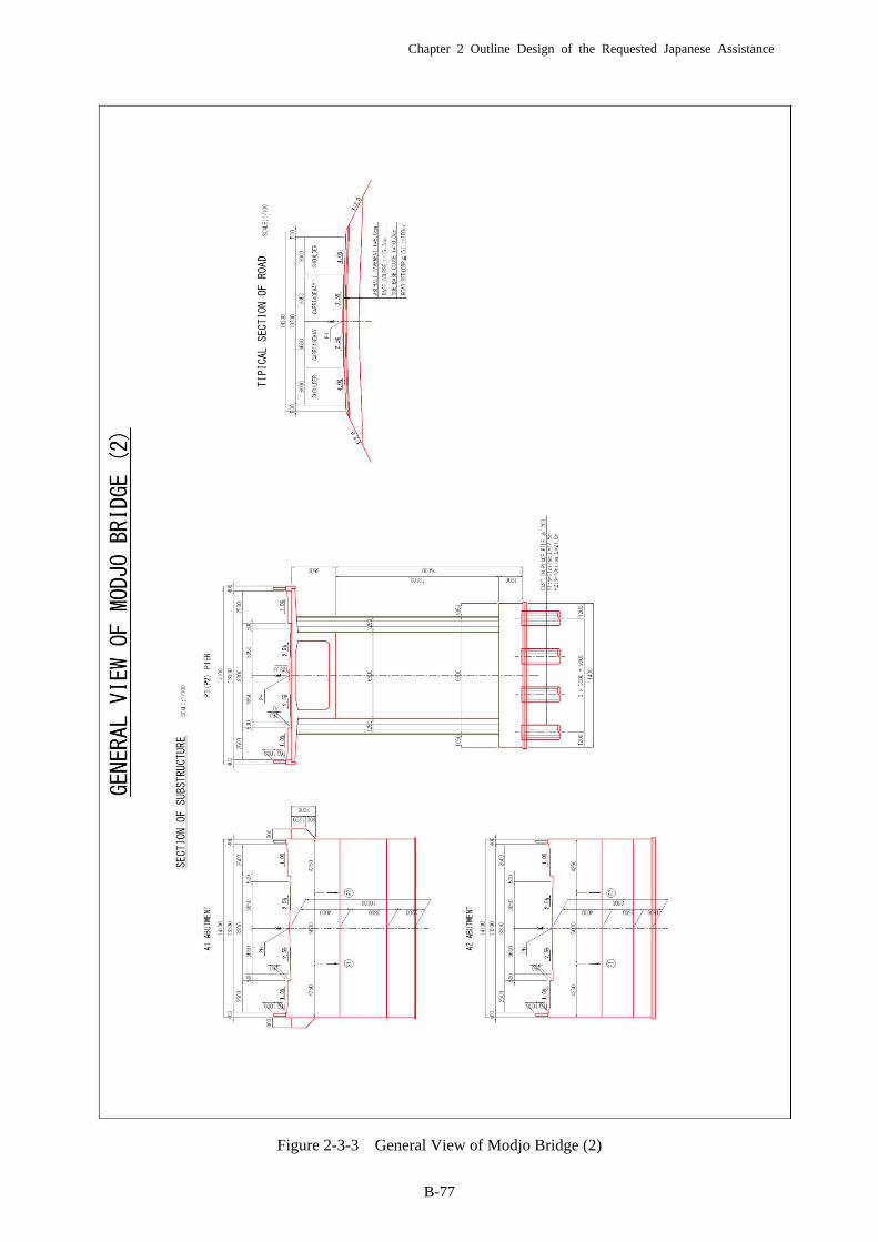
Chapter 2 Outline Design of the Requested Japanese Assistance
B-77
Figure 2-3-3 General View of Modjo Bridge (2)
Chapter 2 Outline Design of the Requested Japanese Assistance
B-78
2-4 Implementation Plan
2-4-1 Implementation policies
Under the assumption that this project is to be implemented within the framework of the donor
country’s Grant Aid, the following will be considered as the basic policies for the examination on
construction methods.
① In order to contribute to creation of employment opportunities and promotion of
technology transfer, the project shall utilize local engineers, laborers, materials and
equipment as much as possible.
② Close communication shall be established between the Government of the Federal
Democratic Republic of Ethiopia (Ethiopian Government), the consultant and the
contractor for smooth implementation of this project.
③ The Ethiopian Government shall be requested to secure land required for the
implementation of this project (removal of houses and compensation for land
expropriation) by its commencement as a work in the scope of works of the recipient
country.
④ Steep slopes and exposed rock surface characterizes the natural condition of the
construction sites. At such sites, there is a high risk of workers and equipment at
work slipping down slopes in the rainy seasons. Appropriate construction methods
and implementation schedule shall be designed with such a risk taken into
consideration.
⑤ A practicable implementation schedule incorporating all possible measures for safety
management during the construction shall be designed with the periods required for
procurement of materials and equipment and adoption of appropriate construction
methods under the restrictive topographic condition of landlocked Ethiopia taken into
consideration.
2-4-2 Implementation Conditions
(1) Maintenance of safety during the construction period
The following are the principal measures for the maintenance of safety during the construction period.
・ Since the access roads to the construction sites for the construction vehicles diverge from the
existing A1 Trunk Road at all three sites, traffic controllers shall be stationed at the junctions
of the access roads and the trunk road and sufficient numbers of construction signboards,
traffic signs and traffic safety equipment shall be installed at appropriate locations.
・ At sites where certain work has to be implemented in a river, implementation of work near a
river should be minimized in the rainy seasons because the water level may rise suddenly at
some of these sites.

Chapter 2 Outline Design of the Requested Japanese Assistance
B-79
(2) Environmental conservation during the construction period
The following are the principal measures for environmental conservation during the construction
period.
・ Creation of dust by the traffic of construction vehicles shall be suppressed with measures such
as spraying water and imposing speed limit.
・ Because of noise and vibration created by construction machinery, construction work shall not
be implemented in the early morning or in the night.
・ Since the construction vehicles will use the detours, measures shall be taken to minimize
adverse effects caused by the traffic of vehicles and machinery involved in this project on the
traffic of ordinary vehicles.
(3) Strict adherence to the Labor Standard Act
The contractor shall adhere to the laws and regulations on construction work which are in force in
Ethiopia, respect appropriate labor conditions and customs associated with employment, prevent
conflicts with laborers and maintain the safety of work with them.
(4) Strong awareness against danger at the project sites
The construction site is far from the presumed mined area and has been searched for landmines. The
construction will commence under the assumption that the site is free of landmines. Nevertheless,
people involved in the construction work shall always remain on the watch for landmines with the
above-mentioned fact in mind.
(5) Customs clearance
All construction materials and equipment procured from the donor country and third countries
(including South Africa) will be transported to and unloaded in Djibouti and cleared customs.
Therefore, the number of days required for the transport, unloading and customs clearance shall be
estimated and the estimated number of days shall be taken into consideration when designing the
implementation plan.
(6) Emphasis on quality control of concrete
The substructure work of constructing Abutments A1 and A2 of the two bridges and Piers P1 and P2
of Modjo Bridge and the superstructure work of constructing concrete girders are considered principal
construction works in this project of constructing the three bridges. In short, the concrete work is
considered as the principal work. Therefore, the construction shall have to be executed with the
highest priority on the quality control of concrete, including quality control of materials such as
aggregate, sand, water and cement, regulations on specifications of a concrete mixing plant,
regulations on transport of concrete and management of concrete casting and curing.

Chapter 2 Outline Design of the Requested Japanese Assistance
B-80
2-4-3 Scopes of Works
If this Grand Aid project is to be implemented, the scopes of works of the donor country’s side and the
Ethiopian Government will be as follows:
Table 2-4-1 Scopes of works of the Donor Country’s side ant the Ethiopian Government
Scope of works of the Japanese side Scope of works of the Ethiopian side
・ Implementation of the cooperation project described in the “Basic Plan,” i. e. construction of new Gogecha Bridge (bridge length = 38 m) with access road (40 m) and new Modjo Bridge (bridge length = 95 m) with access road (40 m)
・ Construction and removal of temporary facilities (material/equipment yards, offices, etc.)
・ Safety measures for the works and general traffic passing through the construction areas during the construction period
・ Measures to prevent environmental pollution by the construction work during the construction period
・ Procurement, import and transport of construction materials and equipment described in “Procurement Plan”: Re-export of imported equipment
・ Preparation of implementation design, tender documents and agreements, assistance in tender and supervision of the construction work described in “Consultant Supervision”, including monitoring of the environment management plan
・ Land expropriation required for this project, removal of facilities and houses to be affected by the project and smooth relocation of residents
・ Provision of lots for the temporary facilities required for this cooperation project free of charge
・ Issuance of IDs to the people involved in the construction and stickers to construction vehicles
・ Provision of a waste material disposal plant required for this project
・ General monitoring of the construction areas during the construction period
・ Supervision by relevant personnel of the Government of Ethiopia during the construction period
・ Removal of the existing bridges ・ Exemption from customs duties, domestic taxes
and other levies in the taxation system imposed by the Ethiopian Government
・ Assistance to Japanese nationals and nationals of third countries involved in the project in their entry and stay in Ethiopia
・ Payment of bank commissions (opening of a bank account and processes of authorization to pay (AP) )
2-4-4 Consultant Supervision
(1) Basic policies for the consultant supervision
Under the assumption that this project is to be implemented within the framework of the Donor
Country’s Aid, the following have been selected as the basic policies for the consultant supervision.
・ Since quality of construction work affect the life and durability of the completed facilities
significantly, the consultant shall perform supervision with quality control as the highest priority
issue. Since Modjo Bridge is a long bridge (95 m) and uses the box-girder structure, the concrete
work for superstructure and substructure works should be closely monitored.
・ The next highest priority shall be placed on the supervision of the progress of the project, safety and
payment.
・ In order to perform the supervision mentioned above, the contractor and the consultant shall inspect
the construction sites together and hold a regular meeting every week to verify problems and
discuss measures against the problems.
Chapter 2 Outline Design of the Requested Japanese Assistance
B-81
・ In addition, representatives of the client of the project/the office in charge of road construction and
maintenance, the Ethiopian Roads Authority, the contractor and the consultant hold regular monthly
meetings to verify problems and discuss measures against them.
・ The consultant shall employ a local engineer as an assistant to the full-time on-site supervisor and
facilitate technology transfer in consultant supervision, including methods for quality control,
progress management and safety management.
・ Instruction to the contractor and minutes of all the meetings shall be recorded in writing and
reporting to the client shall be done in writing.
(2) Consultant’s supervisory work
The major components of the works included in the Consultancy Agreement are as follows:
1) Tender document preparation stage
The consultant will prepare implementation design of each facility in accordance with the conclusions
of the outline design survey report. Subsequently, the consultant will prepare construction agreement
documents and obtain approval for the following documents from ERA of the Ethiopian Government.
・ Design Report
・ Drawings
・ Tender documents
2) Construction tender stage
ERA, with assistance from the consultant, will select a donor country’s contractor in an open tender.
The agent selected by the Ethiopian Government who takes part in the processes from the open tender
to the conclusion of a construction agreement shall be authorized to give approval to all the matters
concerning the construction agreement. The consultant shall provide assistance to ERA in the
following services:
・ Tender notice
・ Pre-qualification
・ Tender and evaluation of bids
3) Construction supervision stage
After the conclusion of a construction agreement between the contractor selected in the tender and the
representative of the Ethiopian Government, ERA, the consultant will issue an order to commence the
construction to the contractor and commence construction supervision. The consultant will report
progress of the construction directly to ERA, the Embassy of Donor country in Ethiopia and send
monthly reports by mail to other relevant personnel and offices, if necessary. The consultant will
supervise the contractor in administrative activities related to the progress and quality of the work,
safety and payment and in the technical aspect including provision of measures and suggestions to
improve the construction work.
Chapter 2 Outline Design of the Requested Japanese Assistance
B-82
The consultant will conduct a defect inspection a year after the completion of the supervision. This
inspection will be the last of the consultancy services.
(3) Personnel plan
The personnel required in each of the detailed design, construction tender and construction supervision
stages and their duties are as follows:
1) Detailed design stage
・ The Project Manager will supervise the technical aspect and general coordination of the detailed
design and act as the primary contact person for the client
・ A bridge engineer (superstructure work) will carry out field surveys, structural calculation,
preparation of drawings and quantity surveying for the superstructure design
・ A bridge engineer (substructure work) will carry out field surveys, structural calculation, stability
calculation, preparation of drawings and quantity surveying for the substructure design
・ A road engineer will carry out linearity calculation, selection of the final standard section,
examination on slope protection work, road drainage design, preparation of drawings and
quantity surveying for the road design
・ A river engineer will carry out field surveys, structural calculation, stability calculation,
preparation of drawings and quantity surveying for the river structure design
・ A person in charge of implementation schedule and estimation will prepare an implementation
schedule and carry out estimation using design quantities and unit prices of works derived from
the outcome of the detailed design.
・ A person in charge of tender documents will prepare tender documents
2) Construction tender stage
The consultant will provide assistance to ERA in finalization of pre-qualification and tender
documents, implementation of the pre-qualification and evaluation of bids.
・ The Project Manager will supervise the above-mentioned consultancy services throughout the
tender process
・ A bridge engineer will approve tender documents and provide assistance in bid evaluation
3) Construction supervision stage
・ Project Manager will supervise the consultancy services in general in the construction
supervision
・ A full-time on-site engineer will take overall responsibility of the on-site construction supervision,
report the progress of the construction to the relevant Ethiopian authorities and hold discussion
with them
・ A structural engineer will revise the implementation schedule for the bridge and revetment works,
supervise the concrete work and control PC tension in superstructures. (S)He will verify the
bottom surface for the foundation work to be revealed after excavation and, if necessary, take
charge of adjustment on-site of the foundation work.
Chapter 2 Outline Design of the Requested Japanese Assistance
B-83
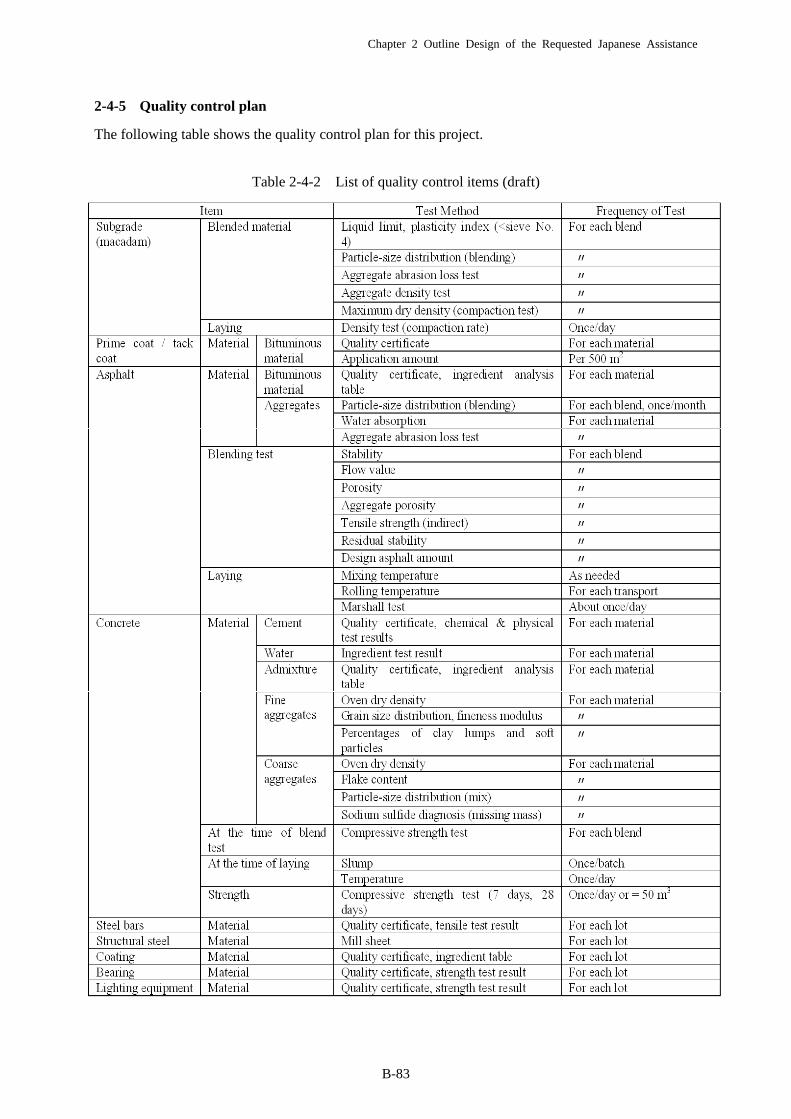
2-4-5 Quality control plan
The following table shows the quality control plan for this project.
Table 2-4-2 List of quality control items (draft)

Chapter 2 Outline Design of the Requested Japanese Assistance
B-84
2-4-6 Procurement Plan
(1) Procurement of construction materials
Construction materials which can be produce locally include sand, aggregate, base course materials.
The rest will be imports.
The basic policies for the procurement of materials are as follows:
・ An imported material will be procured if it is always available at the market and has sufficient
quality.
・ A product which cannot be procured locally will be procured from donor country or third
countries. Decision on procurement sources will be made after comparing such factors as prices,
qualities and periods required for customs clearance.
The table below shows potential sources of procurement of major construction materials.
Table 2-4-3 Possible Procurement Sources of Main Construction Materials
Donor country
Reason for choosing procurement from Donor
Chapter 2 Outline Design of the Requested Japanese Assistance
B-85
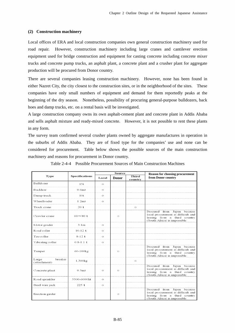
(2) Construction machinery
Local offices of ERA and local construction companies own general construction machinery used for
road repair. However, construction machinery including large cranes and cantilever erection
equipment used for bridge construction and equipment for casting concrete including concrete mixer
trucks and concrete pump trucks, an asphalt plant, a concrete plant and a crusher plant for aggregate
production will be procured from Donor country.
There are several companies leasing construction machinery. However, none has been found in
either Nazret City, the city closest to the construction sites, or in the neighborhood of the sites. These
companies have only small numbers of equipment and demand for them reportedly peaks at the
beginning of the dry season. Nonetheless, possibility of procuring general-purpose bulldozers, back
hoes and damp trucks, etc. on a rental basis will be investigated.
A large construction company owns its own asphalt-cement plant and concrete plant in Addis Ababa
and sells asphalt mixture and ready-mixed concrete. However, it is not possible to rent these plants
in any form.
The survey team confirmed several crusher plants owned by aggregate manufactures in operation in
the suburbs of Addis Ababa. They are of fixed type for the companies’ use and none can be
considered for procurement. Table below shows the possible sources of the main construction
machinery and reasons for procurement in Donor country.
Table 2-4-4 Possible Procurement Sources of Main Construction Machines
DonorReason for choosing procurement from Donor country
Chapter 3 Obligations of the Recipient Country
B-86
Chapter 3 Obligations of the Recipient Country
The duties to be performed by the Ethiopian Government with regard to the implementation of this
project by Japanese Government are as follows:
3-1 General matters in the Donor Country’s Aid
・ To provide data and information required for the project implementation
・ To secure land required for the project implementation (land for road construction, work areas,
camp yards and material/equipment depots)
・ To level each construction site before commencement of the construction
・ To open an account under the name of the Ethiopian Government with a bank in Donor country
and issue Authorization to pay”
・ To unload goods destined for Ethiopia quickly at the unloading sites and process application for
tax and customs duties exemption appropriately
・ To exempt donor country’s corporations and nationals involved in this project from customs
duties, domestic taxes or any other taxes imposed upon provision of products or services
described in the authenticated agreement.
・ To allow people involved in the project entry into Ethiopia and their stay in Ethiopia and Donor
country for the implementation of the work, in accordance with the approve agreement or with
regard to the service provision
・ To grant permission or other authorization for the project implementation, if necessary.
・ To maintain, manage and protect the facilities to be constructed in the project correctly and
effectively.
・ To bear the all the costs within the scope of works of the project except those which should be
borne by the Donor country’s Aid
3-2 Matters specific to this project
・ Removal of facilities and houses affected by the
construction
・ Securing of land required for this project in addition to the
sites of the existing roads
・ Provision and leveling of lots for the temporary yards
・ Places to collect construction materials
・ Provision of place to dispose of waste soil and a waste
material disposal plant
・ General monitoring of the construction areas during the
construction
(To be completed prior to the
Prequalification (PQ) notice)
Chapter 4 Project Operation and Maintenance Plan
B-87
Chapter 4 Project Operation and Maintenance Plan
The Ethiopian Government will supervise implementation and maintenance of this project. The
Road Network Management Division in the Engineering and Regulatory Department has jurisdiction
over maintenance of bridges and roads and the Bridge Management Section in the same division is in
charge of maintenance of bridges and structures. The Pavement Management Section in the Road
Network Management Division is responsible for road maintenance except for those on brides and
structures.
In the implementation structure for the maintenance of the two bridges, Gogecha and Modjo Bridges,
ERA Head Office carries out surveys of current situation, prepares a repair and renovation plan and
applies for budgetary funding and ERA local offices repair and renovate the bridges. Alem Gena
Regional Office is responsible for Gogecha and Modjo. The maintenance works after the completion
of this project are classified into those to be implemented every year on a regular basis and those to be
implemented once in several years. The works mentioned below are required for this project.
(1) Inspection and maintenance required to be implemented every year
・ Removal of sand and waste accumulated in drain pipes, near bearings and in drain ditches
including side ditches on the bridge surface and cleaning of the pipes, bearings and ditches
・ Maintenance of the traffic safety works, such as reapplication of paint on signs on road surface.
・ Inspection and repair of the revetment and bed protection works after flood.
・ Removal of stones fallen down and washed-away trees after the flood
・ Weeding on shoulders and slopes
(2) Maintenance to be implemented once in several years
・ P Patching or overlaying of pavement on the bridge surface and access roads to be implemented every
five years or so
・ Replacement of expansion joints every 10 years or so
In this project, the revetment and bed protection works play an important role in protecting the bridges.
These works are designed to stand the 100-year design flood discharge. However, these structures
may collapse or be washed away because of unpredictable local erosion or a flood larger than the
100-year flood. The survey team requests ERA to establish a system in which a section in charge of
the revetment and bed protection works inspects bridges immediately after flood and, if damage or
collapse has been confirmed on these works, ERA is able to repair damage or collapse immediately.
If such damage or collapse is left unrepaired, the back-filled earth behind an abutment may be washed
away and the loss of the earth may develop into subsidence of the abutment and shut-off of traffic, in
the worst case scenario.
Chapter 5 Project Cost Estimation
B-88
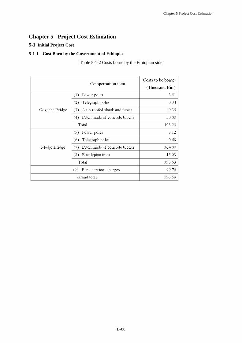
Chapter 5 Project Cost Estimation
5-1 Initial Project Cost
5-1-1 Cost Born by the Government of Ethiopia
Table 5-1-2 Costs borne by the Ethiopian side
Chapter 5 Project Cost Estimation
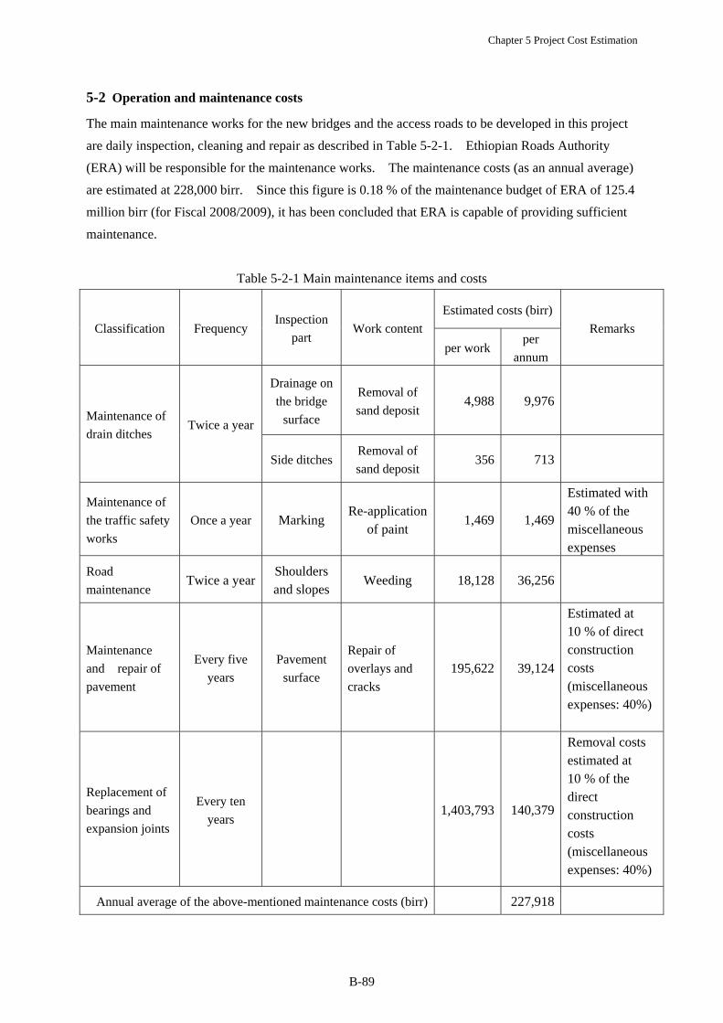
B-89
5-2 Operation and maintenance costs
The main maintenance works for the new bridges and the access roads to be developed in this project
are daily inspection, cleaning and repair as described in Table 5-2-1. Ethiopian Roads Authority
(ERA) will be responsible for the maintenance works. The maintenance costs (as an annual average)
are estimated at 228,000 birr. Since this figure is 0.18 % of the maintenance budget of ERA of 125.4
million birr (for Fiscal 2008/2009), it has been concluded that ERA is capable of providing sufficient
maintenance.
Table 5-2-1 Main maintenance items and costs
Classification Frequency Inspection
part Work content
Estimated costs (birr)
Remarks
per workper
annum
Maintenance of
drain ditches Twice a year
Drainage on
the bridge
surface
Removal of
sand deposit 4,988 9,976
Side ditchesRemoval of
sand deposit 356 713
Maintenance of
the traffic safety
works
Once a year Marking Re-application
of paint 1,469 1,469
Estimated with 40 % of the miscellaneous expenses
Road
maintenance Twice a year
Shoulders and slopes
Weeding 18,128 36,256
Maintenance
and repair of
pavement
Every five
years
Pavement
surface
Repair of
overlays and
cracks
195,622 39,124
Estimated at 10 % of direct construction costs (miscellaneous expenses: 40%)
Replacement of
bearings and
expansion joints
Every ten
years 1,403,793 140,379
Removal costs estimated at 10 % of the direct construction costs (miscellaneous expenses: 40%)
Annual average of the above-mentioned maintenance costs (birr) 227,918