Embed Size (px)
Citation preview

2008WORLD FINANCIAL
CRISIS
2016
1992DOUBLE STACK
CONTAINERSERVICE
20041994
1980STAGGERS ACTDEREGULATES
RAILROADS
1984
1970CONGRESS
CREATESAMTRAK
1965100 TONCARENTERSSERVICE
1964 1974
2009WARRENBUFFETBUYS BNSF
Jamieson Equipment Company | 800.875.0280 toll free | [email protected]

1904 112th ANNIVERSARY 2016As any motorist or truck driver knows, there are more trains running today than at any time in recent decades. It is not uncommon to see four great diesel locomotives hauling 120 tank cars or hopper cars, with a fifth locomotive bringing up the rear. These trains, over a mile long, can carry as much as 24 million pounds of raw materials at speeds exceed-ing 60 mph. And there are also many more mixed freight trains, delivering the myriad materials and products that the manufacturing and processing industries of America need and produce.
No one knows the actual amount of rail usage by industry category. There are no official statistics on this, but our own sales records tell an interesting story. In one three month period, we found that we had sold our rail safety and track maintenance products to nearly 200 different kinds of industries. These range from petrochemicals, food processing and explosives, to resin coatings, wine products, and even amusement park miniature rail-roads. We are sure that a longer survey would expand the list even more. The economics of railroading are making themselves felt in every industry.
It is just this diversity of rail-using customers, and their repeat business over the years, which have helped Aldon remain in business for 112 years. In issuing this 2016 catalog, we take the opportunity to thank all of our customers — industrial firms, railroads, contrac-tors, and our large family of Aldon distributors — for helping us achieve this milestone.
Basic Spur Track Safety .......................................................... 2-25
Essential spur track safety
products

© 2016, Aldon Company, Inc.
Warning Signs, Signals and Lights ......................................... 26-31Signs, Flags, Delineator Tape, Solar Lights, Battery Lights,Motion Sensors
Working with Rail Cars ............................................................ 32-45Loading and Unloading Hopper Cars, Loading andUnloading Box Cars, Tank Car Safety, Moving Cars, Rerailers
Track Inspection and Maintenance ........................................ 46-57Rolling Gauge Readers, Levels, Gauges, Measuring Tools, Stringlines, Gauge Rods, Carts, Dollies, Switch Lubricants, De-Icers, Rail Benders, Tie and Rail Handling, Track Jacks, Track Tools
Car and Locomotive Repair .................................................... 58-59Wheel Slings, Car Stand, Traction Motor Dolly
Truck Dock Safety ................................................................... 60-63Trailer Stabilizing Jacks, Wheel Blocks
Plant Safety ............................................................................. 64-67Portable Crane Stops, Walk-Over Bridge, Flashing Lights
Helpful Information ................................................................ 68-71OSHA Regulations, Track Maintenance Tips, Rail Size Chart
Product Index .......................................................................... 72-73

Bas
ic S
pur T
rack
Saf
ety
— S
WIT
CH S
TAN
D
The Switch: How a train gets where it’s going
FROG
SWITCH POINTS
TARGET
SWITCH STAND
The railroad switch is a marvel of engineering. The ability to smoothly divert a fast-moving train from one track to another is really what makes railroading possible.How a track switch worksA switch creates two tracks — the main track and a side track turning either left or right (the photo shown above is a right-hand turnout). The heart of a switch is a pair of tapered rails called points which lie between the running rails and are slightly narrower in gauge. The points are hinged at one end and are controlled at the sharp end by a connecting rod from the switch stand next to the track. When the switch stand lever is thrown, the points move from one running rail to the other. As the points move from side to side, a pair of sign plates (called targets) on the switch stand turn 90 de-grees. Traditionally these targets have consisted of one green plate and one red plate. The targets can be seen from either end of the switch, but only one color is visible at a time. The color of the target indicates the position of the switch. When the switch points are moved a 5-inch gap is created alongside one of the running rails. This gap permits the wheel of the car or locomotive
to go straight through the switch (indicated by a green target) or into the turnout (indicated by a red target).At the other end of the switch, where the main track separates from the side track, a “V”-shaped steel casting creates a gap on either side of the “V” to permit wheels to pass through on either track. The section of the switch is called a “frog” because it resembles frog legs.
main trackside track
main track
side track
frog
frog
Switch is lined for travel on main track.Traffic in side track cannot enter switch.
Switch is lined for travel on right-hand turnout. Traffic approaching points end of switch can enter switch but can only go into side track.
No traffic on main track can enter switch from frog end.
main track
side track

3
This is a left-hand switch which has been “lined” or positioned for travel through the switch on the main track in both directions. The green target indicates “through travel”. Note the gap between the right-hand point and its rail. Normally a switch is kept positioned for main track travel.
Looking at a switch from both ends ...
Mind the Gap!How to “Read” Switch Points ...Always check to see if the positioning of the switch points agrees with the switch target — Here’s how: Stand facing the switch points and look for the gap between the one point and its running rail.Run your eye along that rail and follow it through the switch; this is the way the wheels will go. Then ask yourself, “Is this the direction I want the train to go?”
P O I N T S E N D
F R O G E N D
Now this left-hand switch has been “lined” or positioned for move-ment into the side track. There are two ways to know this. The gap between the left-hand point and its rail will guide the rail car wheel along the curve of the turnout. The red target confirms that the switch has been lined for a turnout.
The other end of the left-hand switch shown above. (Note that everything is reversed: the main track is now on the left and the side track is on the right). From this distance it is often difficult to see how the points at the other end of the switch are positioned. Thus, the worker must depend on the color of the switch targets to know whether the switch is lined for main track through travel or for movement in and out of the turnout. In this case, the green target indicates that traffic can only proceed on the main track in either direction.
The red target indicates that the switch has been repositioned for in and out movement on the side track. No main track move-ment is possible through the switch. If you go through a switch that is lined against movement on your track, you risk derailment and damage to the switch.
FROG
MAIN TRACK SIDETRACK
SIDETRACK MAIN TRACK

4
Bas
ic S
pur T
rack
Saf
ety
— S
WIT
CH S
TAN
D
1. An inexperienced worker maynot know how to “read the points” or understand the meaning of conven-tional switch targets when aligning the switch.
2. Workers operating locomotives canmisunderstand the meaning of con-ventional targets and wind up forcing their way through a switch that was lined for the converging track
Switch Cube Indicator®A new kind of switch target
Why use a Switch Cube® Indicator?
Switch Cube® Indicator can be installed on any brand or model of low-rise track switches.
No doubt where the train will go

Your choice of “red stop” or “double yellow” for frog end of switch.
Points End: lined for through traffic Points End: lined for turnout
Switch Cube® Indicator: Red Stop Switch Cube® Indicator: Double Yellow
4015-160 Left 4015-163 Right 4015-164 Left 4015-165 Right
5
Frog End of the SwitchSwitch Cube® Indicator is even more valuable when viewed from the frog end of the switch.
Points End of the Switch
Frog End: lined for through traffic
Frog End: lined for turnout Frog End: lined for turnout
Switch Cube® Indicator makes it clear
The convergence of two tracks calls for a more explicit indicator of which track is open for travel and which is not. Switch Cube® Indicator provides this.
NOTE As with any switch target, always “read” the switch points to be sure they are positioned as the Switch Cube® Indicator sign plates denote.
See Switch Cube® Indicator in action at aldoninfo.com/switchcube
Each Switch Cube® Indicator includes a mounting platform custom made for your switch stand mast and 4 replaceable aluminum plates.
platform platform platform platform
Custom sign plates which identify specific tracks can replace the green arrow plates — contact us for details.

Only 20 lb. effort needed to throw a switch. Replaces heavy cast iron throw handle found on most switch stands.
Easy-Throw Replacement Switch Handle Safety Hook for Switches
4124-217 Models 12 RT, 12 RTH, 224124-217-B Models 50A, 51A4124-217-A Model 364124-318 Switch Stand Padlock
6
Bas
ic S
pur T
rack
Saf
ety
— S
WIT
CH S
TAN
D
The Safety Hook tempo-rarily takes the place of a padlock, which ordinar-ily is used to prevent unauthorized movement of a switch.
Meets FRA Regula-tion 218.103 (Switch Stand Securement) and 218.107 (Derail Secure-ment).
Formed steel hook and stainless chain can be bolted to tie, always ready for use.
4024-303
Safety Hook is especially useful for restraining the throw handle of a spring-action switch. Hook can also be used to temporarily secure hinged derails.
“DERAIL INSURANCE” for Switch Points
Track Gauge Control Rods(Non-Insulated) 4127-02 Track gauge at the points end of a switch must be held tight to 56-1/2” or the switch points will not lie close against their running rails. Any gap between the point and the rail can allow a wheel flange to open up the gap and cause a derailment. If your track switches are not equipped with a gauge plate, install an Aldon double-end Gauge Control Rod just in front of the switch points. The double jaws at each end of the Control Rod grip the base of the rail and prevent widening of the gauge. Lock nuts hold the jaws tightly in place.SEE MORE INFORMATION ON PAGE 50.
Switch Cube® Indicator for special track configurationsSimple Wye: Left/Right 3-Point Turning Wye Track

Replacement Switch TargetsIt is important that the targets be replaced when damaged or missing. A rusty or bent target can cause confusion.
4115-166 4115-174
National Trackwork TargetManual switch stands 1004 & 1004 ARS
Plates are 6” x 5-1/4”. Fits round adapter sleeve. Set includes one red plate and
one green plate (or one red and one white). Adapter sleeve is sold separately.
7
4015-166 Switch Number
A teaching aid for new workers and an ever-present reminder on how to “Read the Points.”
Mount sign plate on switch tie outside the rail and next to the switch points. With a glance, worker can reference the sign when either lining or approaching the switch.
“LOOK AT THE GAP” sign plates 18” x 7” .080 Aluminum
4015-275 Left-Hand Switch
Track and Switch sign plates13” x 7” .080 Aluminum
These tie-mounted sign plates are useful reminders of where you are in a rail yard. Specify track and/or switch number(s) when ordering.4015-159 Track Number
Tie-Mounted Signs
New Century TargetManual switch stands: 50A, 51A, 51B
4115-1734115-164 4115-168 4115-172
Plates are 6” x 5-1/4”. Fits 1-1/4” adapter sleeve.
Fits round mast. Sold in sets of two red/green plates (or two red/white plates). Plates attach directly to the mast.
Racor TargetManual switch stands: 20P, 22E, and 36E
Sold as a set: one red and one green plate (or one red and one white). Adapter sleeve is sold separately.
4015-276Right-Hand Switch

Bas
ic S
pur T
rack
Saf
ety
— S
WIT
CH S
TAN
D
For Industrial Spur Switches
8
ECONOMICAL POINT PROTECTIONSwitch Point ProtectorThe Protector is a pad of cast manganese steel bolted to the web of the rail two inches in front of the switch point blade of the curved closure rail (circled in the photo, above). The pad momentarily bumps a wheel flange away from the tip of the point, with no damage to switch point or car wheel. The pad can be reversed when one end is worn down.
to order: Identify your rail size and section. If your rail size is not shown, contact us.
Switch Point Protection WHY PROTECT A SWITCH POINT?To reduce derailments, that’s why!
The sharp ends of switch points are vulnerable to wheel battering as trains round into the turnoff track. The Switch Point leading into the spur track gets the brunt of the wheel hammering. If a switch point tip gets mangled, it will not lie flat against the running rail. Any gap between the switch point and the running rail will allow a wheel flange to slide in, “pick the point” open, and derail.
4123-77-DASCE: 100 LB
4123-77-ENYC: 105 LBPS: 130 LB
battered point
Switch Point Protection
Fits rails 85 lbs. to 141 lbs. /yd. Grips base of switch point and base of running rail. Fine screw threads and 3-point handle bring switch point tight against main rail to within 1/32”. Can be padlocked without any loss of tightness. Weight 10 Ibs.
Switch Point Lock for longer term lock-out
4123-77AREMA: 100 LBARA-A: 100 LBAREMA: 110 LB
4123-77-AAREMA: 112 LB, 115 LB, 119 LB
4123-77-BAREMA: 131 LB, 132 LB, 136 LB 140 LBAB: 141 LB NYC: 127 LB.
4123-77-CASCE: 85 LB, 90 LB. ARA-B : 100 LB PS : 100 LB
A Protector pad will extend the service life of your switch points. Pad can be turned end-for-end to prolong service life. For use in yard tracks where speed is 5 mph or less.
High-security, wiggle-proof design.
#4023-07 (padlock sold separately)
4123-77-GAREMA: 133 LB
4123-77-HAREMA: 141 LB
4123-77-IARA-A 90 LB
Railroad PadlocksFor derails, switch stands, and other rail equipment.
4124-97leaf brass
4124-318solid, plated
4124-319solid, plated
4124-318steel w/chain
diameter inside length inside widtha. a” 1Q” ,”b. v” 2” w”c. v” 1”1” w”d. 2” 1” 18”
a.
b.
c.
d.
SHACKLEDIMENSIONS

9
Track Clearance Marker (exposed rail)Aldon’s permanent, highly visible and all-weather Track Clearance Marker tells
switching crews how far they can shove a car without “fouling” converging tracks.
4015-144
Workers switching a cut of cars at this industrial rail yard misjudged how far they could shove the lead car towards the switch. There was no marker in the track to tell them where to stop. Railroaders call this situation “fouling the track.” Left uncorrected, a fouled track will cause a collision with a passing train.
FEATURES• Moldedinaspecial,stableformofurethane• Bendsifstruckandspringsbackupagain.No
damage to passing trains• Brightyellowglossyfinish—easytoseeat
night; in winter, easy to spot in snow-packedtrack.
• Low-profile—only10”abovetie.• Withstandsanytemperatureextreme-50°to+140°
• Canbeboltedtotieinexposedrailorintocon-crete in flush rail.
Track Clearance Markers can be used to indicate parking limits at loading docks.
Don’t Foul the Track!
Use to comply with Federal Railroad Administration Rule 49 CFR 218.101“...(c) Each railroad shall implement procedures that enable employees to identify clearance points and a means to identify locations where clearance points will not permit a person to safely ride on the side of a car.”
Track Clearance Marker (flush rail)A low-profile bright yellow urethane marker indicates parking limits on tracks encased in concrete or asphalt. Marker is 36” long by 6” wide x 1” thick, and protrudes only 1” above pavement, and so offers no interference with locomotive plows or rail car brake rigging. Marker is installed perpendicular to rails at the same distance as required for exposed track clearance markers (see chart below). In concrete paving, marker is anchored with lag bolts and expanding shields. For asphalt paving we provide 12” long drive spikes. Keep the marker visible in winter by sweeping it clear of snow when you clean the switch points.
4015-146 Asphalt Pavement 4015-156 Concrete PavementDo not install markers on asphalt in coldweather to avoid weakening the pavement.
RECOMMENDED INSTALLATION for Track Clearance MarkerTrack Clearance Markers should be installed on both tracks converging on a switch.
Markers should be placed at least 50 feet from points measuring 13 feet on-center to the adjacent track.

Bas
ic S
pur T
rack
Saf
ety
— D
ERA
ILS
10
One car rolling into another
Unauthorized locomotive coupling to stationary car
A loose car rolling out onto the mainline
Derails help prevent:How Derails WorkThe derail lifts the flange of the wheel and drops it clear of the rail. At the same time the wheel on the other rail falls down between the rails. The derailed wheels bite into the soft surface of ties and ballast and slide to a stop. Depending on speed, a derailed car or locomotive may travel some distance before stopping.
Effective derailing depends on• Derailproperlysized,installed,andmaintained• Carsandlocomotivesmovingatslowswitchingspeeds
(less than 5 mph)• Flattrack— no grades• Trackopentothetiesandballast• Incurvedtrack,derailinstalledonouterrail,notinner
rail• Ampleopenspacealongtrackforderailedcarorloco-
motive to come to a stop
Derails are emergency stopping devices for rail cars and locomotives. OSHA, FRA, and DOT regulations require derail protection for all active rail sidings.

Derails Control Movement
Hinged DerailsSpiked to two ties. Derails can be flipped on or off rail by hand or by
using lifting lever . For rails 80-141 lbs.
Retractable Hinged DerailsDerails slide on and off rail
with 29 lb. handle pull.for rails 90-141 lbs.
SaberTooth®Portable Derails
Tool-free installation.Tie-biting anchor hook.1-way: rails 90-141 lbs.
2-way: rails 100-136 lbs. IMPORTANT INFORMATION ON DERAILS
Type of Ties Wood or Steel?Hinged derails can be installed directly on wooden ties. Steel ties require an adapter plate (see page 13). Retractable and portable derails must be installed on wooden ties only.
Derail Throw Direction?
Rail Size Portable derails fit rail sizes, 90-141 lbs. andup. Hinged and retractable derails are made in four standard sizes, each of which fits a specific range of rail sizes. Request our derail sizing form to determine which size derail you need. You will need to measure the height of the rail. See page 17 for guidance.
Note that direction of throw is fromthe viewpoint of the oncoming locomotive or rail car.
11
Type of Rail?All three types of derails are designed to be used on exposed rail (open to the ties). DO NOT USE DERAILS on flush rail (rail that is encased in pavement).
exposed
1-way or 2-way Derail? Consider the type of rail move-ment you have on your spur tracks. One purpose of the derail is to prevent unauthorized locomotive entry into your siding. Another purpose is to prevent a freight car on your siding from rolling out onto the main line. A further purpose is to prevent one rail car from rolling into another car.
One-way Derails can be used with 4-axle locomotives: 6-axle locomotives: and all freight cars:
Two-way Freight Car Derails can be used with 4-axle locomo-tives: and all freight cars: Do not use if 6-axle loco-motives operate on your siding. The deflection angle is too sharp to handle the longer wheel base . Note that railroads are replacing older 4-axle locomotives with bigger 6-axle units for switching industrial spur tracks. Check with your local railroad to determine what size of locomotive is likely to be switching cars on your tracks.
Two-way Locomotive Derails can be used with 4-axle: or 6-axle locomotives: as well as all freight cars:
We have successfully tested our hinged and portable derails at 6 mph. Higher speeds may cause a failure to derail.
CORRECT
INCORRECT
2-way1-way left 1-way right
Protect your spur track from unauthorized locomotive entry
Do not install hinged derails on concrete or resin ties
Curved Track In curved track, for more assured derailing, always install the derail on the outer curved rail. Wheels naturally hug the outer rail as they round into the curve, and thus are more likely to climb over the rail and into the bal-last. Conversely, wheels tend to draw away from the inner curved rail on entering the curve, thus reducing the like-lihood that a derail installed on the inner rail will carry the wheel over the rail.

Hinged Derails For rail sizes 80-141 lbs. and wooden ties.
4014-01 Left Throw with manual lift sign 4014-10 Left Throw with Pop-Up signWeight 156 lbs.
12
4014-03 Two-way Freight Carwith manual lift signWeight 170 lbs.
4014-02 Right Throw with manual lift sign4014-12 Right Throw with Pop-Up signWeight 156 lbs.
One-Way Derails
Two-Way Freight Car Derail
Derail block is lifted on or off the rail either manually or with a Lifting Lever (4014-28, page 13). Sign Holder is available in two styles: manual lift or Pop-Up.
4014-18 Two-way Locomotivewith manual lift signWeight 170 lbs.
Two-Way Locomotive Derail
Low-angle deflection bar accommodates longer wheel base of 6-axle locomotives. Allow ample space alongside the track for derailed vehicle to slide to a stop.
4014-14 Two-way Freight Carwith Pop-Up signWeight 170 lbs.
DO NOT USE THIS DERAIL if 6-axle locomotives operate on your tracks. Use our 2-way locomotive derail (below) or our retractable derail (page14) instead.
4014-20 Two-way Locomotivewith Pop-Up signWeight 170 lbs.
Permanently installed on two ties. Derail block with wheel-deflecting bar is swung on or off the rail as needed. Can be padlocked in either position. Derail must be sized to fit a specific rail height. For more details, request a copy of our installation guide. All derails are designed for travel speeds under 5 mph. Any higher speed may cause a failure to derail.
For more convenience and greater safety, we now offer a Pop-Up sign holder for our hinged derails.The weight of the derail block when swung on the rail causes the sign holder to rise. When the derail block is swung off the rail the sign holder falls down to the ties.
Lift derail block on or off rail by hand or with lifting lever (#4014-28, page 13).
All hinged derails come with blue derail sign and a manual lift derail sign.
suitable for freight cars, and 4-axle locomotives
suitable for 6-axle and 4-axle locomotives and all freight cars
Two-Way Freight Car Derail is shown in use with Pop-Up sign holder and optional lifting lever.
suitable for 6-axle and 4-axle locomotives and all freight cars
Bas
ic S
pur T
rack
Saf
ety
— D
ERA
ILS

Order derail separately. Request derail sizing form for use with adapter plate. The adapter plate is custom made and is not returnable.
Weight 250 lbs.
4014-13Steel adapter plate, 1 in. thick is welded to three steel ties. Custom-sized derail is bolted to plate. Plate accommodates all types of rail clips. Plate must be bought with a specially-sized derail.
Adapter Plate for Installing
Hinged Derails on Steel Tie
Track.
Hinged Derail Accessories
13
Don’t run over your derail because you didn’t see it!MoonSign is 18” diameter (overthree times the area of the usual blue derail sign). White retro-reflective facing and oversized DERAIL lettering on both sides mean MoonSign can be seen at a greater distance night or day than the usual small blue derail sign.MoonSign sign plate fits any Aldon de-rail sign holder, hinged or portable.4015-185
4015-32Small but brilliant flashing mini-light with magnet base/steel clip.
4115-01Flashing Blue Light
4115-17Flashing Red Light
4014-25 for 1” thick derail block.
4014-28 for 3/4” thick derail block.
Lifting Levers (handle effort 20 lbs. to flip derail)
DERAIL DERAIL
4124-97Padlock
Replacement Derail Sign Plates
(reflective lettering)
10” diameter, round, printed on both sides
of .080” aluminum4015-71
Blue
4015-72Red

4114-10-L One-way left throw.Weight 460 lbs. 4114-10-R One-way right throw. Weight 460 lbs.4114-11 Two-wayWeight 550 lbs.
Designed for freight cars and all sizes of locomotives. One-way or two-way derailing. Install on wooden ties only. Handle effort 29 lbs. to slide derail. Minimum height of rail 52 in. Assembly includes derail, connecting rod, stand, and sign. Customer furnishes two 14 ft. wood switch ties to sup-port operating stand.
Designed for slow switching speeds — less than 5 mph.
RETRACTABLE DERAILwith Operating Stand
Bas
ic S
pur T
rack
Saf
ety
— D
ERA
ILS
14
Wheel Shover works with RetractableDerail (above), to give a sideways shove to wheels to increase the chance of derailing. The addition of a Shover is recommended for difficult track conditions such as curved track or track where switching speeds are above normal.
WHEEL SHOVER is connected to the Retractable Derail so that when the derail slides onto its rail, the Shover slides against the other rail like a switch point. Derail and Shover retract together to permit clear passage of rolling stock.
Standard WHEEL SHOVER is non-insulated. If you need insulation protection, contact us for special pricing. WHEEL SHOVER can be connected to existing Retractable Derail installations.
4114-12Wheel Shover
One-Direction: Left(pictured to right)
4114-14Wheel Shover
One-Direction: Right
4114-13Two-Direction Wheel Shover
One-Way Left Throw

SaberTooth® PORTABLE DERAILSTemporary Derailing Protection for exposed rails on wooden and pre-stressed concrete ties.One-way and two-way derailing for industrial sidings and approaches to buildings. Aldon portable derails stand 2w in. above top of rail to meet current railroad locomotive clearance requirements. Designed for slow switching speeds — less than 5 mph
• Formed Steel Plate Housing. No welds in shear plane to fail. Full contact with rail head.
• Safety Hook. If brace bar notch should slip off tie plate, hook bites into tie. Prevents derail from slipping.
• Tool-free installation. No wrenches needed.Four thumbscrews anchor derail to rail head. No damage to rail surfaces.
Patented design:
4014-06-S left throw (pictured)
4014-07-S right throw
For 4-axle and 6-axle locomotives andall freight cars.
rails 90-141 lbs., wooden ties, tie spacing: 18-24 in.
Weight 35 lbs.
Blue derail sign and holder are included with all derails.
4014-09-S Two-wayrails 100-136 lbs., wooden ties, tie spacing: 19-24 in.
Weight 50 lbs.
For freight cars and 4-axle locomotives only. Do not
use with 6-axle locomotives
U.S. Pat. #7,753,317
15
Weight 7 lbs
16
Bas
ic S
pur T
rack
Saf
ety
— S
IGN
HO
LDER
S
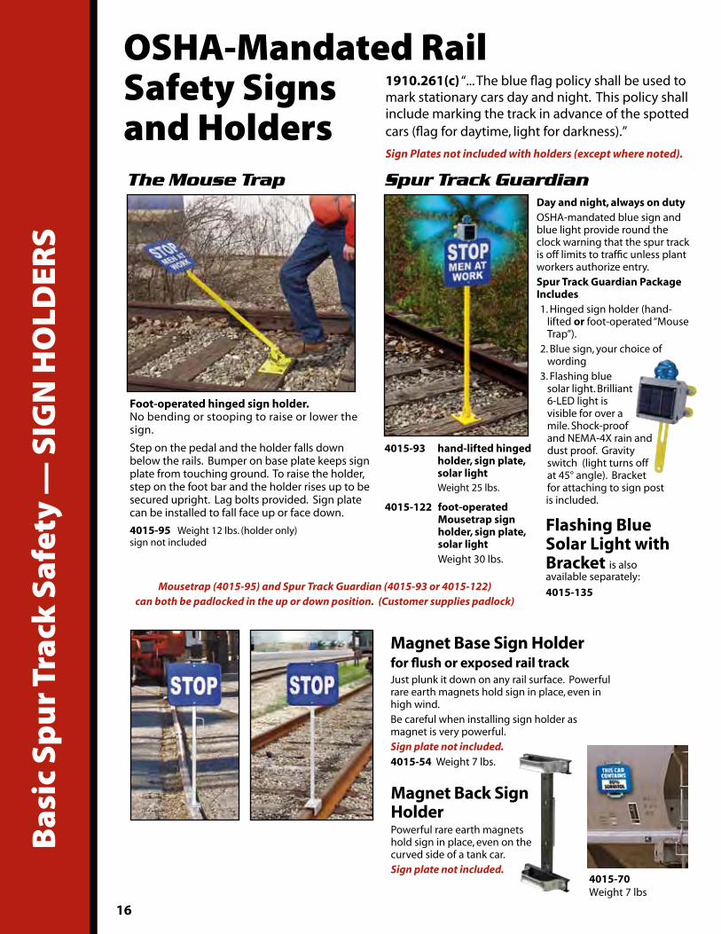
Magnet Base Sign Holderfor flush or exposed rail trackJust plunk it down on any rail surface. Powerful rare earth magnets hold sign in place, even in high wind.Be careful when installing sign holder as magnet is very powerful.Sign plate not included.4015-54 Weight 7 lbs.
Mousetrap (4015-95) and Spur Track Guardian (4015-93 or 4015-122)can both be padlocked in the up or down position. (Customer supplies padlock)
Magnet Back Sign HolderPowerful rare earth magnets hold sign in place, even on the curved side of a tank car. Sign plate not included.
4015-70
OSHA-Mandated Rail Safety Signsand Holders
1910.261(c) “... The blue flag policy shall be used to mark stationary cars day and night. This policy shall include marking the track in advance of the spotted cars (flag for daytime, light for darkness).”
Sign Plates not included with holders (except where noted).
Foot-operated hinged sign holder.No bending or stooping to raise or lower the sign.
Step on the pedal and the holder falls down below the rails. Bumper on base plate keeps sign plate from touching ground. To raise the holder, step on the foot bar and the holder rises up to be secured upright. Lag bolts provided. Sign plate can be installed to fall face up or face down.
4015-95 Weight 12 lbs. (holder only)sign not included
Day and night, always on duty OSHA-mandated blue sign and blue light provide round the clock warning that the spur track is off limits to traffic unless plant workers authorize entry.Spur Track Guardian Package Includes 1. Hinged sign holder (hand-
lifted or foot-operated “Mouse Trap”).
2. Blue sign, your choice ofwording
3. Flashing bluesolar light. Brilliant6-LED light isvisible for over amile. Shock-proofand NEMA-4X rain anddust proof. Gravityswitch (light turns offat 45° angle). Bracketfor attaching to sign postis included.
Spur Track GuardianThe Mouse Trap
4015-93 hand-lifted hinged holder, sign plate, solar lightWeight 25 lbs.
4015-122 foot-operated Mousetrap sign holder, sign plate, solar lightWeight 30 lbs.
Flashing BlueSolar Light withBracket is alsoavailable separately:4015-135

NEW! CUSTOMIZED SIGN PLATES
17
Tripod HolderTwin sockets can hold flags.4015-04Weight 9 lbs.
4015-260 through 4015-269 in red or blue
OSHA BLUE FLAGSAluminum .080” x 12” x 15”. Reflectorized. Weight 1.5 lbs. lbs.OSHA and FRA require blue signs on any track where locomotives of the railroad serving your plant will operate. Red signs may be called for in special situations. Red signs satisfy OSHA Blue Flag Rule.
4015-18-B 6STOP-B 6SAFE-B 6SCC-B 6STCC-B 6SCAW-B 6SMAW-B 6DERAIL-BB
Equivalent French and Spanish wordings available.
4015-18-R 6STOP-R 6SAFE-R 6SCC-R 6STCC-R 6SCAW-R 6SMAW-R 6DERAIL-R
Clamp-OnSteel holder. Clamps to rail head. Easy on, easy off.NON-LOCKING (shown)4015-01 Weight 7 lbs.LOCKING4015-07 Weight 10 lbs.
Sign Helper4”x18” aluminum sign plate with angled lines makes your OSHA signs much more visible. Blue with scotch-lite white.4015-181 Weight 1 lb.
Hurricane-ProofSteel holder with padlock. Withstands 75 mph wind.4015-10 Weight 10 lbs.
Coupler HolderGooseneck handle fits into hole in coupler.4015-03 Weight 4 lbs.
Spike-Down HingedBase is spiked to tie. Hinged sign holder folds down in either direction. Lockable (customer provides padlock).4015-06 Weight 16 lbs.
Sign Holders (sign plates sold separately)
Clamp-On AluminumEasy-open holder never rusts. Double roll bar for stability.4015-52 Weight 4 lbs.
Clamp-On InsulatedFor use near electrified third rail. Fiberglass arm and urethane end fittings.4015-02 Weight 4 lbs.
Permanent HingedBolts to base of rail. Holder folds down flat.4015-05 Weight 15 lbs.
15” x 15” sign plates with standard OSHAwording and space for your custom text
“THIS CAR CONTAINS” 12” x 15” red or blue sign plate with vinyl label to identify contents of a rail car. Use with magnet backed sign holder (4015-70) to adhere to side of rail car. Labels can be easily changed.
4015-271 blue4015-272 red
MIN. ORDER
for custom
sign plates:
2

Cast Steel Wheel Chocks
18
In 1955 Aldon Company introduced cast steel chocks with the unique feature of replaceable spurs (or teeth). The spur is the key to effective chocking. Under wheel pressure the spur
bites into the hard, smooth surface of the rail to keep the chock
from sliding. But eventually, like the blade of a knife, the spur edge will become dull from use.
A dull spur can’t bite into the rail to keep the chock from sliding. You can keep the sure grip of an Aldon wheel chock by turning the spur to three new sharp edges and then replacing the spurs at nominal cost instead of buying a new wheel chock.
Aldon Chocks have the Edge
A gust of wind is enough to cause a 260,000 pound freight car to start rolling. Thanks to roller bearings, freight car wheels offer very little resis-tance to movement. In fact, the
contact area of each wheel on the rail is smaller than the size of a dime. This is why moving heavy loads by rail is so efficient! But at the same time, all this mass, so easily moved, needs to be securely blocked while the car is being worked.
It’s easy to turn and replace worn spurs in Aldon Chocks
Why Use Wheel Chocks?
Chock spurs have four edges. When the first edge becomes dulled from use, you can tap the spur out of its slot and re-insert it with a fresh edge exposed. By turning the spurs at intervals you extend the service life and effectiveness of your wheel chock.
Ask for our free booklet on changing out spurs or go watch our two-minute video on chock spur maintenance.
Made of 1/2” sq. alloy steel. Heat treated for a hard, sharp edge6008
Bas
ic S
pur T
rack
Saf
ety
— C
HO
CKS
Replacement Spurs
Loading freight cars increases the strain on the car brakes. Liquid pouring into a tank car or a forklift moving back and forth in a boxcar create dynamic forces which can overcome the holding power of the brakes.
Slack in mechanical car brakes can be enough to allow a wheel to move forward a few inches and dislodge a dock board or strain a hose line.
This why OSHA mandates the use of wheel chocks in addition to car brakes wherever rail cars are being worked.

19
Idle Car on Storage Track Car Being Worked - Flat Track
If the track is flat and there is no vibration, double chocks at each end can be used to block car movement. Set brake before chocking.
Double chocks on each end of the car provide two-chock blocking against movement in either direction. Set brake before chocking.
What Kind of Rail Do You Have?One type of chock does not fit every rail situation. Aldon offers flush rail chocks and exposed rail chocks. Exposed rail is open to the ties. Flush rail is encased in pavement, with only a flangeway left open on the inside of both rails for wheels to pass through.
Single Chocks or Double Chocks?Recommended chocking procedures for single cars on flat track
open to the ties and ballast
encased in pavement with only a flangeway
on inside of rail
EXPOSED RAIL FLUSH RAIL
Car Being Worked - Slight Dip
If the car tends to roll in one direction, single chocks at each end may be sufficient. Set brake before chocking.
double chock double chock chock chock double chock double chock
Do not use wheel chockson sloped track.
Car on sloped track
Brake then chock. Chock both wheel sets. Do not use chocks on sloped track.
Recommended chocking procedures for multiple cars on flat track
Use double chocks. On flat track, where a line of rail cars remain coupled together, and are moved forward progressively to be loaded/unloaded: Brake and chock the car to be worked (chock both ends of the car). It may be necessary to set the brakes on several cars depending on your operating conditions. When the first car is ready to be moved, remove the chocks and release the brakes on the cars. Move cars forward and repeat the braking and chocking procedure. If cars are uncoupled to be worked separately, brake and chock each car.

Cast Steel Wheel Chocks with Spurs
Single Chock with Flag (28” handle)4011-01 (A) Exposed Rail Weight 13 lbs.4011-02 (A-1) Flush Rail Weight 13 lbs.
Double Chock with Flag (28” handles)4011-06 (C) Exposed Rail Weight 16 lbs.4011-07 (C-1) Flush Rail Weight 16 lbs.4011-08* (C-2) Exposed Rail Weight 20 lbs.
*with tension clamp and padlock
Single Chock (15” handle) 4011-09 (D) Exposed Rail Weight 6 lbs.4011-10 (D-1) Flush Rail Weight 8 lbs.
Double Chock (15” handles) 4011-03 (B) Exposed Rail Weight 12 lbs.4011-04 (B-1) Flush Rail Weight 12 lbs.4011-05* (B-2) Exposed Rail Weight 20 lbs.
*with tension clamp and padlock
Single Chock with Flag(44” handle)
Double Chock with Flag(44” handles)
4011-14 Exposed Rail Weight 14 lbs.4011-15 Flush Rail Weight 14 lbs.
4011-16 Exposed Rail Weight 26 lbs.4011-17 Flush Rail Weight 26 lbs.
20
Stay-Clear Hi-Visibility Chocks with Flag
Keep your head and hands away from the rail car when placing wheel chocks.Handle length of 44 in. makes it easy to place the chock under the wheel while staying clear of the car body. Added handle length makes it easy to see the chock even down a long line of cars. Cast steel chock with replaceable spurs insures effective car blocking.
Standard Chocks
Bas
ic S
pur T
rack
Saf
ety
— C
HO
CKS

21
Whack ‘Em Severe Duty Wheel ChocksUnder certain loading/unloading conditions, such as with tank cars, wheel chocks with steel spurs can sometimes get stuck under the wheel. No problem! Aldon “Whack’em” chocks have reinforced steel handles that stand up to hammer blows or yanking the handles sideways.
Whack ‘Em Double Chocks (15” handles)
4011-30 Exposed Rail Weight 14 lbs. 4011-31 Flush Rail Weight 14 lbs.
Whack ‘Em Double Chocks with Flag (28” handles)
4011-34 Exposed Rail Weight 18 lbs.4011-35 Flush Rail Weight 18 lbs.
Whack ‘Em Single Chock with Flag (28” handles)
4011-32 Exposed Rail Weight 16 lbs.4011-33 Flush Rail Weight 16 lbs.
High quality Brake Stick telescopes and locks.User can tighten and release brakes, align car coupler knuckles, operate angle locks, and re-set end-of-train warning devices.
NO NEED TO CLIMB THE LADDER TO WORK THE BRAKE
Two sizes available:4123-104 Standard
27” - 42”Weight 5 lbs.
4123-105 Long Reach67” - 104”Weight 7 lbs.
Brake Stick

Specialty Wheel Chocks
Car-Stopper ChockBring slow-moving car to a stop by thrusting urethane wedge several times in front of car wheel. With each thrust, some of the forward momentum is absorbed. The wedge will hold the wheel temporarily until a steel wheel chock can be installed. A useful means of car control when moving freight cars with a car puller.Use on flat track only.4011-11 Weight 6 lbs.
Nine-Lives Wheel WedgeA practical alternative to using oak wedges as wheel chocks. Wheel Wedge is designed to chock idle rail cars on storage tracks where cars are not subjected to vibration. Molded in a special grade of urethane, the wedge is 10” long ~ 22” high ~ 34” wide. Rail car must be stationary before using wedge. After setting car brake, worker slips wedge under wheel. When the wedge needs to be removed, the worker does not have to stoop down and try to free it from the wheel. Instead, the rail car can run over the wedge repeatedly, with no damage to the wedge and no risk of derailing the car.
•Do not use wheel wedge for cars being loaded or unloaded — use steel wheel chocks instead.
•Use on exposed or flush rail on flat track only.•Do not use if car is raised at one end. All wheels must
remain on the rails.
4011-18 Weight 2 Ibs.
Transit Car Urethane Wheel ChockUrethane double chock with indestructible fiberglass handles for use with transit cars and passenger cars. Apply brakes before installing chocks. Do not use on freight cars being worked or locomotives.Use on flat track only.
4011-12 Exposed Rail Weight 4 lbs.4011-13 Flush Rail Weight 4 lbs.
Ductile Iron Wheel Block (or any freight car)A “SUPER” chock, cast in ductile iron. Use one at each end of car for secure blocking. Can be used on flush rail provided flangeway is created on field side of rail. Clamps grip rail when wedge is pounded tight. Wedge can be padlocked in place.
Use on flat track only.
DO NOT USE FORIMPACT STOPPING
4016-01 For Rails 60-104 lbs. Weight 45 lbs.
4016-02 For Rails 105-175 lbs. Weight 50 lbs.
22
Bas
ic S
pur T
rack
Saf
ety
— C
HO
CKS

23
Rail SkidsCast-steel rail skids (or “skates”) can be used as wheel chocks or as car-stopping devices for slowly moving freight cars. Skids are also a low-profile chock for idling locomotives.As a Wheel Chock (for flat track only): Place skid on each rail a few feet in front of stopped car. Slowly roll car forward so wheels can mount skids. Apply car brakes. Chock other end of car on flat track.As a Car-Stopper (for flat track only): Place skids on each rail, one skid a few yards away from the other. Let car roll forward at 3 to 4 mph maximum speed. Wheels will mount skids and result-ing friction of skid under wheel load brings car to a gradual stop. Note that a skid can be knocked off rail; be sure to have a derail installed further down the track, just in case.
Railroad Service Model S-87 for use on 100 lb. or heavier railFor heavy railroad service — particularly for hump yard tracks where trains are being formed. Features deep “pocket” to capture car wheel. High back keeps wheel from jumping over.Weight 42 lbs.
Replace skids when tongues become deformed.Skid tongue must lie dead flat on the rail to be effective.
Chocking Skid for Flush RailTamper-proof chock for freight cars, or idling locomotives on flat track. Low clearance (4 in. above top of rail). Lip on one side of skid is removed for seating on flush rail. Roll car onto skid and apply brake. Chock other end of car with a conventional wheel chock. Skids are furnished as either “left rail” or “right rail” as viewed from the handle end of the skid.
“Right Rail” Skid is pictured.4” high x 18” long. Weight 13 lbs.
left rail right rail
4016-22-L 4016-22-R
Industrial Service (rails 90-141 lbs.) for use exposed rail
Model S-86For stopping cars and as a wheel chock. Features a “pocket” center to capture wheel.4016-11 Weight 30 lbs.
Model S-61For light to average weight cars, as car stopper and wheel chock.4016-10 Weight 19 lbs.
Model S-78A light-weight skid, useful as a wheel chock on industrial sidings, and to alert engineer when pushing a string of cars into a dead-end siding.4016-09 Weight 13 lbs.
4016-12
yellow4016-12-O
orange

Car Stops and Bumping Posts for Freight Cars
CS-3X Hinged, Locking TypeStops are bolted through web of rail. Stops fold outward when not needed. Lock casting grips head of rail and can be padlocked to prevent unauthorized use of stops. If load is too great, bolts can shear.
CS-2 Self-Tightening TypeWedge holds bolted-together car stop to rail. Stop stands 15 inches above rail. Can be used as chock as well as stopping device. Tighten bolts periodically and re-hammer wedge if loosened.4016-03 Weight 107 lbs.
CS-4 Severe Duty TypeUses the cushioning capacity of the tie and a wheel-bump feature to lift the wheel slightly off the rail to absorb momentum. Recommended for spur tracks where more protection is needed than a conventional car stop can provide.4016-06 Weight 173 lbs.
• CarStopsandBumpingPostsareforuseonflattrackonlyataslowspeed(1-3mph).
• CarStopsarenotequalinstoppingcapacitytoaBumpingPost.Limituseofcarstopstolightlytravelledsidetracks,whereonetotwocarsmaximumarebeingmoved.
• Provideamplespacebetweencarstopsandobjecttobeprotected.• Useasignalmantoguidelocomotiveengineerascarsapproachstoporpost.Repeatedimpactswillweakenstopsandposts.
folds down to outside
of rail
24
Bas
ic S
pur T
rack
Saf
ety
— C
AR
STO
PS Car Separation
Ways To Use Car Stops
Avoid contact between rail car being moved and nearby parked rail cars.Provide ample distance between
stops and car.
Provide additional stopping protection if wheel chocks/brake can’t hold car steady.
Procedure:
2
3
4
1. Install one stop on each rail.2. Ease car up against stops — no impact. 3. Apply brake and chock rear wheels4. For multiple cars use multiple pairs of
stops (1 pair per car).5. Provide adequate means to stop car
movement when car stops are removed.
Chocking on Grades 1% max. slope
Backup for Chocks
1End-of-Track Stop
For car storage tracks and lightly used loading tracks.
Bumping Posts4116-08Light Traffic. Weight 800 lbs.
4116-09Heavy TrafficWeight 1,250 lbs.
To increase awareness of car stops and bumping posts, install a 24” x 24” x 0.080”blank red aluminum sign
approximately 10 feet behind the stops or post
(to clear car coupler).Customer provides4”x4” wooden post.
End-of-Track “Stop” Sign
#4115-44Weight: 4 lbs.
Customer can install middle rails for track strength. Leave 3 to 4 ties worth of rail length behind post.
4016-05-R Right Hand Wt. 94 lbs.4016-05-L Left Hand Wt. 94 lbs.
Car stops are sold in single units but should always be used in pairs.
1-2 cars. Light-duty side track.
1-2 cars. Light-duty side track.
1-3 cars. More frequently used side track.
Longer trains andfrequently used side tracks.
We have three levels of car stopping products based on frequency of use and the length of the train that will make contact with the stop.

25
Don’t Let This Happen to YOU!
4013-01-R
Ratchet Screwweight 170 lbs.
For proper support, install four stabilizing jacks per railcar, one at each end of the car, at the designated location for jacking or lifting the car. Always brake and chock car first, then install jacks. Check jack contact with car body at intervals during unloading as car may rise as it lightens.
Anatomy of an AccidentWhile unloading a hopper car at a Florida cement plant, electric vibrators were left unattended. One of the vibrators stalled, which caused a catastrophic imbalance of load in the car. Stabilizing jacks at all corners of this freight car could have prevented this accident.
Rail CarStabilizing Jacks
Minimum retracted height 26 in. Maximum screw elevation 14 in.
Load Capacity: 75,000 lbs.Top Cap: 38 in. dia.
Base: 19 in. dia.
Install only at designated lifting/jacking pads on rail car. Install at all four corners of rail car.Stabilizing Jacks should never be used to lift a rail car.
Quality Features• Class2GAcmescrewthreadsforasmoothfitand
good support.
• Removablebushingtoallowreplacementofscrewassembly.
• Swivelheadtilts9°toreducesideloadbendingforce.
• Zerkfittingprovidesuniformandconstantlubricationof screw threads.
• Boltandwasherpreventover-extensionofscrew.
• Steelsleeveprotectsaxle.GROUND
Custom-made to fityour rail carsPlease request a sizing form (or download from our website). We will send you a drawing for approval.
SOLUTION:
TOP OF RAIL
LIFT/JACK PADHERE

War
ning
Sig
ns, S
igna
ls a
nd L
ight
s
4015-3712”~15” 2 lbs.
4015-3612”~15” 2 lbs.
4115-4024”~24” 3 lbs.
4115-4218”~24” 3 lbs.
4115-3823”~26” 3 lbs.
4015-19730” 4 lbs.
4015-19624” 3 lbs.
4015-22112”~12” 2 lbs.
6SERVC-B12”~15” 2 lbs.
4015-101
12”~15” 2 lbs.6SIIP-B
12”~15” 2 lbs.
4115-416”~36”4 lbs.
4115-376”~48”
5 lbs.6STOP-O
12”~15” 2 lbs.
6DERAIL-O12”~15” 2 lbs.
4015-18-O12”~15” 2 lbs.
World of Railroad Signs
4015-198 10 lbs.
4015-10212”~20” 4 lbs.
26
2 pieces, each 48” x 9”
Cross Buck Set
Intermodal
Engineering Grade Scotch-Lite Faced Signs.080” Aluminum, drilled for mounting
6SCL-B12”~15” 2 lbs.
6SCU-B12”~15” 2 lbs.
6-SCOC-B12”~15” 2 lbs.
6-PCH12”~15” 2 lbs.
6-STCL12”~15” 2 lbs.
Contact Us
Marker FlagFor fire hydrants, railroad transmission boxes, and other vital equipment.Flexible 6 ft. fiberglass pole with red/white molded flag.Specify hydrant- mounting bracket or box-mounting bracket.
4124-323
Aluminum bracket for Cross Buck (see 4015-198)
For 2-3/8” diameter pipe. Sold in pairs. Use in pairs.
(One pair per Cross Buck set)
4015-199

27
4115-44 4115-46 4115-45 4115-47
4015-94specify speed15”~20” 3 lbs.
4115-3416”~24” 3 lbs.
MagneticLocomotive Cab
Signs
4015-988½”~15” 3 lbs.
4015-968½”~15” 3 lbs.
4015-77specify number of tracks
18” ~27” 8 lbs.
(MUTCD #W15-2)
High intensity retro-reflectivefacing. Highway-Rail Crossing SignsAluminum (.080”) conforms to Federal HighwayAdministration (MUTCD) specifications.
4015-82track to
left of road (MUTCD-W10-4L)
4015-83track to
right of road (MUTCD-W10-4R)
4015-78
4015-80track to
left of road (MUTCD-W10-3L)
track toleft of road
(MUTCD-W10-2L)
track toright of road
(MUTCD-W10-2R)
order 4015-78 and rotate 180°
track toright of road
(MUTCD-W10-3R)
order 4015-80and rotate 180°
4015-7630” dia.
(MUTCD #W10-1)
4015-7434”~34” 20 lbs.
(MUTCD #R15-1)
4015-87
Locomotive Blue FlagPipe holder (7 ft.) hooks to handrail. 2-sided sign plates 12 in. x 15 in.
4115-13920 lbs.
4015-97
Aluminum Bracket for Cross Buck (see 4015-74)
For 4” diameter pipe.Need two per Cross Buck.
Sold in pairs. Need one pair per Cross Buck set.
4115-96
Aluminum sign with wind-resistant rare earth magnet tab. Reflective lettering on both side
36”~36”, Weight 10 lbs.(exceptwhere noted)
4015-7530” x 30”
(MUTCD #R1-1)
4015-148(MUTCD #R1-1)
4015-8624” x 30”
4015-14724” x 18”
signs are 24” x 24” and each weighs 3 lbs.
4015-145specify text
12”~15” 3 lbs.
4115-0914”~20” 4 lbs.
4115-0820”~28” 7 lbs.
Danger Signs 18 ga. Baked Enamel
note:many more danger signs available on our website aldonco.com
Railroad Signs
4015-10336”~24” 6 lbs.
Prepare to Stop24”~24” 4 lbs

Warning Signs, Flags, and Marking Tapes
DANGER! ENTERING BUILDING!Workers riding cars need warning to get off before car enters building. Customer provides sign post.
4015-61 STOP-DISMOUNT sign plate30” dia ~ .080” aluminumWeight 10 lbs.
4015-62 CLOSE CLEARANCE6” ~ 57” ~ .080” aluminumWeight 4 lbs.
28
War
ning
Sig
ns, S
igna
ls a
nd L
ight
s
No-Crossing Signs with Magnet-Base HolderIt is dangerous to walk between two uncoupled freight cars or a freight car and a bumping post. Mark these “no-go” areas with the No Crossing two-sided danger signs (16”x18”) with magnet base aluminum sign holder. Bold graphics can be seen easily from both sides of the track. Magnet base instantly grips surface of flush or exposed rail so worker stays clear of track when installing or removing holder.
4015-186 Do Not Cross Here (car-car)
4015-187 Do Not Cross Here (car-bumper)
Weight of sign and holder
10 lbs.

Magnetic Flag HolderWind-proof magnet base for exposed or flush rail. Twin sockets for d in. dowel staff.
4015-55 Weight 4 lbs
Rail Clamping Flag HolderSteel holder clamps to rail head. Twin sockets for d in. dowel staff.
4015-23 Weight 7.5 lbs.
Flags for all holders are sold separately.
Nylon Flags withWooden Dowel Handle12” ~ 15” , 18” wooden dowel staff. Weight 1 lb.
4015-91 orange4015-92 white4015-21 yellow
Reflective Marking Tape Engineering Grade 3M brand acrylic tape with UV top layer.
Roll size, 4 in. wide ~ 150 ft.
Delineator Tapes for Cars and EnginesDiamond Grade, Reflective3M brand acrylic tape with UV top layer.FRA Rule 49 CFR, part 224.
Roll size, 4 in. wide ~ 150 ft. 4124-322 blue4124-321 red
29
4124-313 white4124-314 yellow
4015-22 green4015-20 red
4015-12 blue4015-120 yellow/red
Tripod Flag HolderPortable aluminum tripod stand can hold two flags and/or a sign.
4015-04Weight 9 lbs

Car Inspector LightIncandescent bulb. Toggle-switch shutoff. Swivel-base.4115-05 Weight 5 lbs.
Trainman’s LanternSignal beam or spot beam at flip of switch.4115-03 Weight 3 lbs.
Flashing Blue Light with Handle7 in. dia. Lexan lens.4115-04 Weight 3 lbs.
Pocket Lights
Clip to vest or belt or use magnet base. Uses single “D” cell battery. Height 42 in. tall. Xenon bulb 4015-191 Blue 4015-192 Red
4015-193 Clear 4015-195 AmberLED bulb for greater brilliance and reduced battery draw
4015-194 Blue
Small enough to slip into your pocket (32 in. wide). Brilliant 4 LED light visible up to 2 miles. Magnet base and belt clip. Uses two AA batteries. 4115-115 Red 4115-114 Blue 4115-117 Amber
BATTERY-POWEREDINSPECTION LIGHTS
Clip-On / Stick-On Lights
30
Flashing solar lights where you need themWho wants to replace and dispose of batteries? 360° solar light flashes 60 times per minute. Bril-liant 6 LED light visible for a mile. Solar battery operates 8 consecutive nights without recharging.
4015-254015-31
magneticbolting
BLUE
4015-334015-34
magneticbolting
RED
4015-584015-59
magneticbolting
CLEAR
AMBER
4015-35magnetic4015-57bolting
Bolt-on bracket
Magnetic bracket
Fully recharges with 2 sunny hours or 8 cloudy hours. External on-off push button conserves battery. Grav-ity switch disconnects light when light is turned to 45° or greater. Aluminum bracket with or without rare earth magnet permits a variety of mounting possibilities on any steel surface.
Weight with bracket, 5 lbs.
War
ning
Sig
ns, S
igna
ls a
nd L
ight
s
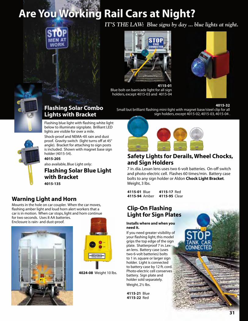
Installs where and when you need it.If you need greater visibility of your flashing light, this model grips the top edge of the sign plate. Shatterproof 7 in. Lex-an lens. Battery case (uses two 6-volt batteries) bolts to 1 in. square or larger sign holder. Light is connected to battery case by 12 ft. cord. Photo-electric cell conserves battery. Sign plate and holder sold separately. Weight, 2½ lbs.
4115-21 Blue4115-22 Red
4115-01 Blue 4115-17 Red4115-94 Amber 4115-95 Clear
7 in. dia. Lexan lens uses two 6-volt batteries. On-off switch and photo-electric cell. Flashes 60 times/min. Battery case bolts to any sign holder or Aldon Chock Light Bracket. Weight, 3 lbs.
31
Safety Lights for Derails, Wheel Chocks, and Sign Holders
Clip-On Flashing Light for Sign Plates
IT’S THE LAW: Blue signs by day ... blue lights at night.
4015-32Small but brilliant flashing mini-light with magnet base/steel clip for all
sign holders, except 4015-02, 4015-03, 4015-04 .
4115-01Blue bolt-on barricade light for all sign
holders, except 4015-03 and 4015-04
Warning Light and HornMounts in the hole on car coupler. When the car moves, flashing amber light and loud horn alert workers that a car is in motion. When car stops, light and horn continue for two seconds. Uses 8 AA batteries. Enclosure is rain- and dust-proof.
4024-08 Weight 10 lbs.
Are You Working Rail Cars at Night?
Flashing Solar Combo Lights with BracketFlashing blue light with flashing white light below to illuminate signplate. Brilliant LED lights are visible for over a mile.Shock-proof and NEMA-4X rain and dust proof. Gravity switch (light turns off at 45° angle). Bracket for attaching to sign posts is included. Shown with magnet base sign holder (4015-54).4015-205
also available, Blue Light only:
Flashing Solar Blue Light with Bracket4015-135

Gatemaster IThe Gatemaster is a compact, simple-to-use manual tool for hard-to-open car gates. Through planetary gear reduction in the Gatemaster head, the worker’s handle effort is multiplied 18½ times - a considerable mechanical advantage. A maximum torque output of 3,200 ft.-lbs. can be achieved by only 173 Ibs. of handle effort. By com-parison, the same effort on a 6 ft. pry bar would only produce about 1,000 ft.-lbs. of torque. There is no loss of effort when using the Gatemaster. The output torque is sustained until the gate opens or the operator releases the torque. Weight 30 lbs.#4020-05 Gatemaster I Assembly
Gatemaster IIAdding an “assistant” torquing unit to the Gatemaster greatly reduces input handle effort needed to achieve full 3,200 ft.-lbs. output. Less worker fatigue results. Weight 35 Ibs.The “assistant” unit’s 2 in. square drive mates with the main Gatemaster unit.Only 35 Ibs. of input effort is needed on handle.#4020-06 Gatemaster II Assembly
GateMaster Hopper Car Gate Opener
4024-06 AL-94 1 in. sq. drive4024-07 AL-116 12 in. sq. drive
12 in. to 14 in. stepped end.Length 5 in. Weight 5 Ibs.2,000 ft./lbs. maximum torque.
Open hopper car gates with your own power equipment
Square Drive Fittings for Air Wrenches
32
GateMaster II in use
Wor
king
wit
h Ra
il Ca
rs —
Lo
ad
ing
/ U
nlo
ad
ing
Ho
pp
er C
ars

Hopper Car Gate Openers
Covered Hopper Cars
Turning Bar for Sliding GatesSix feet long and made of 1a” dia. stress-proof steel, with an angle at one end to clear the side of car. Operator should not jump or stand on the bar.
#4020-03 Weight 30 Lbs.
33
Open Top Hopper Cars
Pry Bar for Swing or Drop Doors
Lightweight
High-Strength
Less fatiguing to use
4020-12 ... 5 fo
ot 13 lbs.
4020-15 ... 3 fo
ot 11 lbs.
Cam-Action Dual Toggle Lock(also recommended for Enterprise-type locks.)
Use 3 foot bar
Wine Gate Lock Miner Type D Lock
Use 5 foot bar
Since these car doors span the width of the car body two workers with pry bars are needed — one on each side of the car — working in tandem to open and close the doors.
Weighing only 13 lbs., the five foot pry bar gives the worker good leverage to swing and lift heavy car doors. Lower section of bar is made of heat treated alloy steel, machined to a narrow wedge end for working into a variety of sockets and forcing stubborn door locks.

Air-Powered Gate Openers for Covered Hopper Cars
WorkmasterWorkmaster produces up to 13,000 ft.-lbs. of energy at 85 psi, 114 cfm with 1 in. air hose. Rubber tires can be flipped sideways to move the Workmaster from gate to gate. Self-closing lever throttle, wheel pivot and forward-reverse controls are all grouped together. Needs 6 ft. of space between side of car and wall. All fittings and controls provided.4120-04 Weight 318 lbs.
High Impact for Corrosive and Sticky Materials
34
Wor
king
wit
h Ra
il Ca
rs —
Lo
ad
ing
/ U
nlo
ad
ing
Ho
pp
er C
ars

35
GATE-JACK Air Powered Opener For opening cars carrying dry, granular, free-flowing materials. The Gate-Jack needs 80-125 psi air pressure and 70 cfm volume of air to produce 1,750 ft.-lbs. of output torque. The Gate-Jack housing mounts directly on the gate’s spindle head. The operator twists the air control valve in the desired direction for the force of
PowerDrive Electric Gate Opener The combination of 1½ hp, 10 rpm gear motor and telescopic drive shaft will open any car gate that is not damaged or ice-bound. Instead of using one-directional, high torque hammer action, the Powerdrive relies on the instantaneous reversibility of an electric motor to “rock” the stuck gate open. The drive shaft angles 20° in all directions and telescopes to reach varying socket positions. The gear motor’s double shaft allows two-track gate
opening. Powerdrive assembly includes gear motor, drive shaft, controls and fittings. By adding the optional Sliding Carriage, the Powerdrive can work its way down a line of gates. (NEMA 4x 230/460 V.)
4020-08 Gear Motor, Shaft, Controls, Fittings Weight 300 Ibs. 4020-11 Sliding Carriage Weight 50 Ibs. (customer supplies
6W20 beam)
the Gate-Jack to be transmitted to the car gate. Control valves and hoses are provided. A 3/8 in. dia. lubricated airline is needed for best performance. The operator furnishes a 3 ft. steel rod (1 in. dia.) to serve as a braking bar.
4120-01 Weight 80 Ibs.

4124-212Barrel Length: 48” Weight: 4 lbs.
4124-213Barrel Length: 36” Weight: 4 lbs.4124-214Barrel Length: 60” Weight: 5 lbs.
Air Broom
Poly Wall ScraperFiberglass pole handle extends to 24 ft. Polyethylene paddle has a 10 in. wide blade. Useful for scraping down bin walls inside covered hopper cars.
Paddle 4124-109 Wt. 2 lbs.Pole 4124-108 Wt. 6 lbs.
Paddle 4023-03 Wt. 2 lbs.Pole 4023-04 Wt. 2 lbs.
The heat-treated aluminum scraper paddle is 5 in. wide with a chisel edge. Six foot long pole extensions snap together to give the worker a long reach into a tank or bin.
Aluminum Car Wall Scraper
Railroad Spill Containment PanPolyethylene pan locks to rail beneath tank cars and hopper cars. The solid pan holds up to 50 lbs. of drips as hoses are connected.
Solid Pan 4124-30 Wt. 5 lbs.w/Drain Holes 4124-29 Wt. 5 lbs.
Wor
king
wit
h Ra
il Ca
rs —
Lo
ad
ing
/Un
loa
din
g H
op
per
Ca
rs
36
Better than a push broom. Clean up dry spillage and unclog hopper chutes with a jet of high pressure air. Air Broom delivers 13.5 lbs. of thrust with 100 PSI inlet pres-sure used. Dead man trigger protects worker. Handle accepts 3/4 in. male NPT pipe thread connections.
Inlet Pressure 100 PSI Thrust (lbs.) 13.5 Flow (SCFM) 140
Molded polyeth-ylene pan is 29” long ~ 14” wide ~ 10” high. Screened drain in bottom lets rain water pass through. 4124-310Weight 9 lbs.
Blue Boat Spill PanFor plastic pellets and other non-soluble materials
In winter, blow snow from track and switches. Better than a broom.
Do Not Exceed 120 PSI Inlet Pressure

37
Pneumatic Piston-Type Car ShakersThe piston shaker has a wedge-end which fits all standard covered hopper car side brackets. The wedge cannot be clamped down or secured in any other fashion except being lodged in the bracket. Lugs on the wedge keep it from becoming jammed in the bracket
Filter / lube / throttle kit available — Contact us.
Caution: always use stabilizing jacks on both sides of the car when using car shakers. See page 25.
Cyl. Use On Part No. Air CFM DB Wt.Size Inlet
3” Dry, granular, 4126-01 3/8” 11 96 73 lbs.free-flowing material
4” Sticky, damp materials 4126-02 1/2” 18 110 115 lbs.which cake
Save your back and your fingers. Stubborn hatch covers yield to the leverage in our specially shaped bar. Worker should be secured to fall protection cable while using Hatch Key™ pry bar.
4020-17Heavy Duty Weight 10 lbs.
4020-16Standard Duty Weight 5 lbs.
Absorbent Track Mat For oil-based products
Provides absorbency and drip protection under rail cars for a wide variety of petroleum-based products. Three-ply construc-tion consists of top layer of needle-punched polypropylene felt, a middle layer of absorbent meltblown polypropylene, and a chemical resistant bottom layer to prevent seepage into ballast.
Mat comes in 100 foot rolls:4123-148 59” wide for inside rails
(absorption capacity: 60 gallons)Weight 70 lbs.
4123-149 Set of two 19” wide panels for field sides of track(absorption capacity: 25 gal.)Weight 60 lbs. per set of 2 rolls
Mat can be walked on. Staking may be need in windy locations.
Hatch Key™Pry Bars
Heavy Duty (Patent Pending) Standard Duty (Patent Pending)
Short videos of both Hatch Key™ Pry Bars are featured in our video library.

Safe Ways to Use Your Forklift to Open Box CarsEasy-Slide* Car Door Opener for dockless rail siding where access to the car door is through a doorway.
Easy-Slide uses leverage and the power of your forklift to fully open or close car doors without damage to forklift or door.
Hook on to door pull tab. Rotate forklift to left to pull door open.
Continue rotating left while backing up.
When door is half-open, pivot to right to change leverage angle.
Drive forward and rotate left to push door fully open.
EASY-SLIDE satisfies OSHA’s “de minimus” exception to the ban against using forklift blades directly to open box car doors.Welded-steel frame fits over paired fork blades up to 7 in. wide. Steel pivot arm stretches 60 in. beyond frame to reach any car door. Pincer hook on pivot arm engages car door pull-tab.EASY-SLIDE opens sliding doors and plug doors.To order, request an EASY-SLIDE sizing form.4020-13 Weight 65 lbs.
*U. S. Patent #8,568,078
Wor
king
wit
h Ra
il Ca
rs —
Lo
ad
ing
/Un
loa
din
g B
ox C
ars
38
No damage to forklift.No damage to car doors.

Safe Ways to Use Your Forklift to Open Box CarsAldor Car Door Opener fortraditional open docks where there is a clear run alongside the box car. Dock must be at least 15 feet wide.
ALDOR design meets OSHA’s “de minimus” exception to the ban on using a forklift to open box cars: Force is parallel to car door so no damage is done to forklift or car door. Forklift and operator remain safely out of the way of the door at all times.
Arm advances in 6 in. increments with hitch-pin lock. Fully extended, beam reaches out over 48 in. gap between dock edge and side of car. 4020-02 Weight 350 lbs.
Fits fork blades up to 5 in. wide. For widerblades contact us.
Adjustable-Length Aldor — Steel
Railroad Dock BoardPortable steel bridge from box car to dock. Lifting loops on dock board allow easy placement by forklift. Curbs at sides of dock board guide forklift driver. Straight-cut or flared approach aprons. Locking rings on each side wedge dock board against dock. Capacities: 15,000 lbs., 22,000 lbs., and 42,000 lbs.4128-01 Request sizing form for pricing.
39
Fixed-Length Aldor — AluminumOverall length, 90 in. Beam reaches out over 48 in. gap between dock edge and side of car. 4020-14 Weight 80 lbs. Fits fork blades up to 7 in. wide.
For wider blades contact us.

Hopper and Tank CarHose Cradle
Broad base polythylene supports hose. Velcro belt keeps hose steady during unloading. Dimensions: 13” high ~ 19” square base
4124-312 Weight 3.5 lbs.Wor
king
wit
h Ra
il Ca
rs —
Ta
nk
Ca
r Sa
fety
40
Tank Car Pry BarMuch better than a crowbar!Designed to engage the grab-handle of tank car manway covers. Five-foot steel pipe handle and a rocking foot provide the leverage to overcome suction caused by the difference in atmospheric pressure outside the tank car and inside. When using the pry bar, the worker can stand upright and avoid the escaping fumes when the lid pops free.
Always wear fall-restraint gear when working on top of a rail car.
4020-18Weight 25 lbs.

Tank Car Safety GateFits over gap in railing on top of tank car. Formed aluminum panel, 48 in. wide ~ 11 in. tall, drops over railing. Handle pro-vided on top of panel.4124-173 Weight 13 lbs.
Tank Car Manway CoverTemporary shield keeps rain and dust out while letting gases escape. Fits standard 20 in. dia. manway. Filter screens are suitable for all resin and food products. Carrying strap.
4124-311Weight 20 lbs.
41
Tank Car Wheel BlockHigh-security wheel blocking. Clamps grip rail head through wedge action. Do not use for impact stopping. Use one chock at each end of the car after brake has been applied. For added security, a padlock can be field-installed to the wedge.Use on flat track only.4016-01 for rails 60-104 lbs. Weight 45 lbs.4016-02 for rails 105-175 lbs. Weight 60 lbs.
Tank Car Safety
Hanging Tool TrayA convenient place to keep small tools when working on the roofs of tank cars. Tray legs fit up to 2” diameter railings on landing platforms and gangways. Welded aluminum with durable yellow powder coat finish. Drain holes in each corner.4024-280
Tray: 24” x 8” x 2-3/4”Legs: 22” highWeight 6 lbs.

HEX Metric 8 PT Metric HEX Metric 8 PT MetricEquivalent Equivalent Equivalent Equivalent
Steel Tank Car SocketsMax torque rating 1500 ft./lbs.
Spark-Resistant Bronze Tank Car SocketsMax torque rating 500 ft./lbs.
Not for impact wrenches. Use hand wrench only.
4024-157
T-Wrenches for SocketsUseful where 200 ft.-lbs. or less torque is needed to loosen or tighten manway cover bolts. Handle is 24 in. with a 36 in. tall staff. Square drive: 1 inch. Safety chain with locking pin to secure socket to wrench.
Aluminum (spark resistant) T-Wrench1a” OD handle4024-195Weight 8 lbs.
Steel T-Wrench7/8” OD handle4024-157Weight 12 lbs.
Wor
king
wit
h Ra
il Ca
rs —
Ta
nk
Ca
r Sa
fety
42
2 in. and w in. square drives available for bronze sockets on special order.
4” bolt clearance
4024-191 1c” 33.3mm 4024-169 14” 31.8mm 4024-193 1c” 33.3mm 4024-194 1c” 33.3mm
4024-274 1a” 34.9mm 4024-192 1c” 33.3mm 4024-170 1v” 36.5mm 4024-175 1v” 36.5mm
4024-158 1v” 36.5mm 4024-163 1v” 36.5mm 4024-171 12” 38.1mm 4024-176 12” 38.1mm
4024-159 12” 38.1mm 4024-164 12” 38.1mm 4024-172 1b” 39.7mm 4024-177 1b” 39.7mm
4024-160 1b” 39.7mm 4024-165 1b” 39.7mm 4024-173 1s” 41.3mm 4024-178 1s” 41.3mm
4024-161 1s” 41.3mm 4024-166 1s” 41.3mm 4024-174 1n” 42.9mm 4024-179 1n” 42.9mm
4024-162 1n” 42.9mm 4024-167 1n” 42.9mm 4024-180 1w” 44.5mm 4024-183 1w” 44.5mm
4024-186 1w” 44.5mm 4024-188 1w” 44.5mm 4024-181 1m” 46.0mm 4024-184 1m” 46.0mm
4024-187 1m” 46.0mm 4024-189 1m” 46.0mm 4024-182 1d” 47.6mm 4024-185 1d” 47.6mm
4024-190 1d” 47.6mm 4024-168 1d” 47.6mm

4119-51 Car Pulling Rope1” diameter double-braided polyester-clad. No hardware or splicing included. Specify length desired.
Maximum safe working load: 20,000 lbs. DO NOT EXCEED Minimum breaking strength: 48,500 lbs.
4119-09B Bronze Thimble and Splicing of RopeRope is sold separately.
One-end or two-end splicing available
Capstan Car Puller Accessories
Coupler Alignment ToolProvides the back-saving leverage needed to bring coupler drawheads into straight-ahead alignment
so car can be coupled.
4124-59 Weight 9 lbs.
Manual Car MoverThe tried and true way to move one rail car short distances. Car mover multiplies worker’s downward handle pressure to lift and nudge the wheel slightly forward.
Movement speed 5 fpm.
Rail-biting spurs provide good traction. Hardwood handle, 54 in. long provided.
Use on flat track only. Another worker should be ready to stop the car with hand brake or urethane car stopping chock (see page 22). Do not use car mover foot as a wheel chock.
4017-01 Mover with handle Weight 20 lbs.4017-02 Replacement handle Weight 6 lbs.
43
4119-51
4019-09D4119-09C 4119-09C Screw Pin ShackleTo connect hook to rope/thimble. Alloy steel, 1” diameter pin.
DO NOT EXCEED SAFE WORKING LOAD: 9.5 metric tons
4019-09D Replacement Hook Alloy steel.Maximum safe working load: 20,000 lbs.DO NOT EXCEED
4119-09B

Cast in high strength alloy steel, these double-end rerailers can carry the weight of heavier railcars. Used in pairs (one inside, one outside) and secured by chains to the rail.
Rail Size 100-131 Ibs. 4018-12-I Inside Wt. 125 lbs.4018-12-O Outside Wt. 125 lbs.
Rail Size 132-152 Ibs. 4018-13-I Inside Wt. 135 Ibs. 4018-13-O Outside Wt. 135 Ibs.
Safety Chain w/hook 4018-09 Wt. 7 lbs.(Need 2 chains per rerailer)
Double-ended “Burlington” style rerailers are locked to the rails by clamps and wedges and will not slip or kick out during rerailing. One “Inside” and one “Outside” make a pair. Rerailers are reversed in direction and exchanged in position to suit different derailed wheel situations. For use with standard size cars.
Rail Size 70-90 lbs. 4118-01-I Inside Wt. 100 lbs.Rail Size 70-90 lbs. 4118-01-O Outside Wt. 100 lbs.
Rail Size 100-140 lbs. 4018-04-I Inside Wt. 169 lbs.Rail Size 100-140 lbs. 4018-04-O Outside Wt. 169 lbs.
“BIG RED” Rerailers for Oversized Cars
“Burlington” Style Freight Rerailers
Straddle-Type Freight Car RerailersThe most practical design. All wheels are rerailed with one place-ment of rerailers. Chain and hook holds rerailers securely to rails. For use with standard size cars.
Rail Size 90-140 lbs. 4018-01-L Left Wt. 169 lbs.Rail Size 90-140 lbs. 4018-01-R Right Wt. 169 lbs.
Rail Size 70-110 lbs. 4018-02-L Left Wt. 135 lbs.Rail Size 70-110 lbs. 4018-02-R Right Wt. 135 lbs.
Rerailers for Freight CarsW
orki
ng w
ith
Rail
Cars
— R
era
ilers
44

Keeps wheels on rails when approaching and leaving weigh scales, unloading pits, etc. Half-diamonds can be installed for single or dual direction car travel. Customer supplies seven 13 ft. cross ties to support each half diamond.
4018-11 20 ton/wheel capacity Weight 6,000 Ibs.4018-23 20 ton/wheel capacity Weight 6,800 Ibs.
Split diamond rerailer can be made for roll-on/roll-off car ferries.
Permanent Rerailer-Split Diamond Consists of Two Half-Diamond Sections
Permanent Rerailer-Full Diamond
Diamond shaped rerailers automatically rerails car wheel in both directions. Diamond panel stands 2” above top of rail to engage wheel flange. Customer supplies 13’ ties to support rerailer. Overall length full diamond 11ft. Overall length half diamond ___ft. Custom-built, not subject to return once sold.
4018-10 20 ton/wheel capacity Weight 10,000 Ibs.4018-22 40 ton/wheel capacity Weight 11,000 Ibs.
45
McCarty Freight Car RerailersAn old and reliable design for two-way rerailing of loco-motives and heavy freight cars. Cast-steel rerailers straddle two ties and hook to rail head. Stout carrying handles at each end butt up against side of ties to keep rerailers from sliding as wheel mounts the ramp. No wedges or spiking needed, just scrape some gravel away from the ties and hook the rerailers to the rail. Ready for action.
Use in pairs: one inside rerailer and one outside rerailer
Rails 90-120 lbs./yd.Inside#4118-14-I Weight 207 Ibs.
Outside#4118-14-O Weight 165 Ibs.
Rails 131-152 lbs./yd.Inside#4118-15-I Weight 211 Ibs.
Outside#4118-15-O Weight 190 Ibs.
2-Man Carrying PoleWorkers can easily carry heavy, bulky items with our 2-Man Carrying Pole. Perfect for rerailers and derails.Carry Pole is 8 feet long, made of steel tubing, with a pincer hook at the center.Maximum load: 250 lbs.4024-54Weight 10 lbs.

A worker can check hundreds of yards of track without having to bend and stoop every few feet to check gauge. Measure up to 2” of gauge variation (56” to 58” for standard gauge track). Insulated roller bearings provide smooth travel (will not go through switches or crossings). Side rollers contact rail 5/8” below head to avoid burrs, but yet pass over joint bars. Easy-to-read gauge scale (1/8” increments) can be read while walking. Scale can be calibrated to a specific gauge before starting out to inspect the track.Standard Gauge 4022-10Weight 33 lbs. (for rails 90 - 141 lbs.)Narrow Gauge 4022-10AWeight 33 lbs. (specify gauge and rail size)
Gauge Restraint ReaderMakes FRA-mandated inspection of yard tracks easier.
At a comfortable walking pace, one worker can verify no-load track gauge, then stop at intervals to apply 4000 lbs. side force to rails, simulating the effect of locomotive wheels on rail.
Reader conforms to FRA 213.110 and 213.53(b) requirements for accurately measuring gauge restraint.
Built like a steel bridge, but breaks into three pieces for easy transport to and from track.
Hinged pressure bar swings down to check gauge restraint at any desired point. Two-speed hydraulic pump advances and retracts pressure bar. Ends of pressure bar contact rail web fillet with 4000 lbs. force.
Trac
k In
spec
tion
and
Mai
nten
ance
46
Telescopic assembly rolls freely through switches and over guard rails and rail crossings. Insulated roller bearings measure gauge 5/8” below top of rail. Bearings can be adjusted lower to clear overflow rail.Gauge Restraint Reader 4022-15Weight 103 lbs. (each section less than 35 lbs.)
Set of Carrying Cases for item 4022-154022-23 Weight 35 lbs.
Economy Track Gauge Reader (does not roll through switches)
Accessories for Track Gauge Reader
Digital Track Level4022-12
Weight 1 lb.
Carrying Case4022-11
Weight 19 lbs.
Distance Counter4022-13
Weight 1 Ib.
47
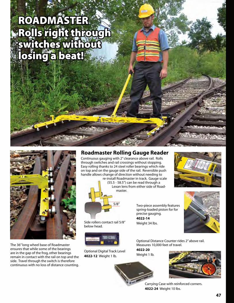
Roadmaster Rolling Gauge Reader
Side rollers contact rail 5/8” below head.
5/8”
ROADMASTERRolls right through switches without losing a beat!
The 36” long wheel base of Roadmaster ensures that while some of the bearings are in the gap of the frog, other bearings remain in contact with the rail on top and the side. Travel through the switch is therefore continuous with no loss of distance counting.
Optional Distance Counter rides 2” above rail. Measures 10,000 feet of travel. 4022-20Weight 1 lb.
Carrying Case with reinforced corners.4022-24 Weight 10 lbs.
Two-piece assembly features spring-loaded piston for for precise gauging. 4022-14Weight 34 lbs.
Optional Digital Track Level4022-12 Weight 1 lb.
Continuous gauging with 2” clearance above rail. Rolls through switches and rail crossings without stopping. Easy rolling thanks to 24 steel roller bearings which ride on top and on the gauge side of the rail. Reversible push handle allows change of direction without needing to
re-install Roadmaster in track. Gauge scale (55.5 - 58.5”) can be read through a
Lexan lens from either side of Road-master.

Aluminum Track Gauge4022-02 Weight 6 Ibs.
Fixed Gauges & Track Levels
Aluminum Track Level 4022-01 Weight 5 Ibs.
Combination Aluminum Level/Gauge 4022-03 Weight 5 Ibs.
Trac
k In
spec
tion
and
Mai
nten
ance
48
Adjustable Aluminum Level & GaugeAn economical way to measure two inches of gauge variation to 1/16” accuracy. Slide rule action and large type scale for easy reading. Gauge setting can be locked with thumb screw. Also measures cross elevation from 1” to 7” with 1/8” accuracy.Two piece56 in. - 58 in. Gauge Range 4022-07Weight 11 lbs.
Three piece56 in. - 58 in. Gauge Range 4022-07-AWeight 11 lbs.
Standard gauge or any custom gauge desired. — english or metric.
Tie GaugerSteel tube center with welded end brackets is strong enough to act as a bridge when bring-ing one tie into proper spacing with another. End brackets are arranged to read four standard tie spacings by rotating the tube center 90°.
Magnetic Track Inspection Tape MeasureMagnetic tip allows one worker to quickly check track gauge. Color coded overlay scale gives toler-ance for out-of-gauge track and cross-checking
guard rail and frog spacing for Class 1 through Class 5 track.
4124-316 25 foot tape Weight 1 lb.
Steel Pipe Gauge4022-05 Weight 30 Ibs.
Rail Head Wear GaugeCombination tool measures head wear vertically and horizontally to an accuracy of 1/32 in. Gauge measures rail sizes 112 lbs., 115 lbs., 119 lbs., 132 lbs., 133 lbs., 136 lbs., and 141 lbs.4124-210 Weight 5 Ibs.
Two size ranges available 4023-76 tie spacings 21”, 22”, 23”, 24”.4023-77 tie spacings 19”, 20”, 23”, 24” Weight of each, 7 lbs.
Tally Clicker Makes any kind of repetitive counting easy, such as count-ing cross ties in a section of track. Slips over index finger. Press tab to count. Turn knob to reset to zero.4124-342

Track Gauge Spreader
Grabs rail head or base to pull or push rails into desired gauge. Can be used in both regular track and within switches. One end of the head-of-rail Spreader model has a double jaw, one of which is offset to lift Spreader above switch point or heel block. Gauging range 16 inches. Reversible ratchet wrench with flip key to change movement direction. Useful for correcting track after derailment and when installing gauge rods. Weight 24 Ibs.4023-50 Head of Rail (Non-Insulated)4023-51 Base of Rail (Non-Insulated)4023-52 Base of Rail (Insulated)
Stringline Rail Curve Measuring Tool
Measure track curvature or visually judge the straightness of straight rail. Steel paddles lock to rail head. The custom 12” ruler measures the space between the rail head and the red-marked midpoint of a 62’ cord. Each inch of space between rail and string equals one degree of curvature.Accuracy of measurement is +/- 4%.4024-03 Weight 5 Ibs.
Rolling Distance Counter
Four foot circum-ference wheel with hard rubber tire measures up to 10,000 feet. Side of wheel has 1in. marks on one side and 10ths of an inch marks on other for very accurate distance measuring.
Easy-to-read dial shows “feet” in white digits on black band.
Brake prevents acciden-tal backward movement of counter. Rotary knob allows dial to be cleared instantly. Rail guide keeps product on surface of all rail sizes while rolling.
4024-02 Weight 13 lbs.
49
4023-50
4023-51

4127-02 (Double End) Weight 38 lbs.
Track Gauge Control Rods “DERAILMENT INSURANCE”
Trac
k In
spec
tion
and
Mai
nten
ance
50
Spur Track Maintenance and Security
The main cause of derailments in industrial rail yards is over-wide track gauge. Locomo-tive and freight car wheels can exert as much as 4000 lbs. of side pressure against the rails. If the ties are spongy, they can lose their spike-holding strength and allow the rails to be pushed over from wheel side pressure. A between-the-rails derailment requires crane-lifting to put the car or engine back on the rails and extensive track repair.
A simple preventive measure for gauge spread is to install Aldon double-ended gauge control rods every 8 feet in high traffic track. If your switches do not have gauge plates at the points end, install a double-ended gauge rod at the approach to the switch as well.
4127-01 (Single End) Weight 28 lbs.
A pair of iron jaws at each end of the double-ended gauge rod grip the rail base to hold the rails to gauge and keep the rails upright against wheel pressure.
For curved track, use the single-ended gauge rod. Jaws at one end attach to the base of the outer curved rail, which re-ceives the greatest wheel side pressure. The hook at the other end grabs the base of the inner rail.
(Non-Insulated)

51
Track De-icerSold in 5 gallon containers. Non-flammable and diluteable. (Use with spray tank 4123-79)4123-129 Weight 20 Ibs.
Sprayable Graphite GreaseKeeps switch points and switch stands from rusting and sticking. Flammable material shipping regulations apply.4124-106 4 gaIs./caseWeight 40 Ibs.
Why strain your back? Each cart half weighs only 49 lbs. Deck area 48 in. square expanded aluminum grid. Parking brake for safety. Jack-knife ease of installation on rail. Wheels are 6 in. dia. aluminum insulated.
4025-03 Weight 98 lbs.
Two-Piece Miracle Cart• WeldedAluminum• Only49Ibs.topickup• 5,000Ibs.provenloadcapacity
Two-Piece Steel Push Cart5,000 lbs. capacity. Each cart haIf weighs 93 lbs. Assembled deck area 53 in. ~ 48 in. Deck is non-skid expanded steel. Cart comes with U-shaped push handle. Wheels are 6 in. dia. aluminum with insulated bearings. Parking brake holds cart steady.
4025-02 Weight 185 Ibs.
Carts should be used on flat track only
Track Bolt Ratchet WrenchPowerful leverage and ratchet convenience in one wrench. Handle is 38 in. long, with 1 in. square drive.
Wrench only: 4123-112 Weight 11 lbs.
1c in. 8 pt. 4124-14012 in. 8 pt. 4124-1431b in. 8 pt. 4124-1441w in. 8 pt. 4124-1471d in. 8 pt. 4124-149
Sliding Rail AnchorFall ProtectionWeight 6 lbs.
R.R. RAIL CRANE RAIL4124-49 90-136# --4124-49A -- 171#4124-49B -- 175#
1” Square Drive Sockets
Super Magnet Picker Upper
Handle length adjusts from 22” to 38”
4124-61
Magnet Capacity: 3 lbs.
Magnetic Switch Broom HolderA handy way to carry a switch broom on board a switching locomotive or Trackmobile.
4023-20 Weight3 Ibs.
Powder coated stainless steel holder (60” long) has two pairs of powerful rare earth magnets to hold it in place on side wall of locomotive or shunter. Drain hole at bottom. (Broom sold separately)
4023-19
Switch BroomTough polypropylene bristles clean out flangeways in flush rail as well as keep switch points and switch frogs clean of debris, ice, and snow. Handle end has chisel blade for small scraping jobs.

#4021-06, 07
25 & 30 Ton BendersBend conventional strength rail for switch point pockets and rail repairs. Available with Screw Jack (25 ton) or Hydraulic Ram (30 tons).
Rail Benders for Heavy & Light Rail
Hydraulic BendersCurve mine rail and make other rail repairs. V-shaped bender frame available with 25-ton hydraulic ram-pump or 50-ton ram with remote pump. Spring return retracts ram when relief valve is turned.
Trac
k In
spec
tion
and
Mai
nten
ance
52
H E A V Y R A I L - 9 0 # - 1 4 1 #
Part No. Ram Size Rail Size Weight4021-06 25 tons 60-70# 138 lbs.4021-07 25 tons 25-60# 195 lbs.4021-09 50 tons 60-85# 170 lbs.
#4021-09
HYDRAULIC MODEL
Screw Jack (AL-200-S) Part No. For Rails Weight4021-02 60-140 lbs. 184 lbs.
Hydraulic Ram (AL-200-H) Part No. For Rails Weight4021-01 60-140 lbs. 184 lbs.
M I N E R A I L - 2 5 # - 8 5 #
Rail Thermometer (Fahrenheit) Features 4-magnet base.4124 -18 Weight 1 lb.
R A I L B E N D E R A C C E S S O R I E SRope Pull Aparts1in. dia. fiberglass rope. Soak in kerosene and use to heat rail head prior to welding. Sold in 125 ft. lengths.4124 -17 Weight 23 lbs.
Rail TuggerSelf-locking wedge grabs rail for easy pulling and positioning of rail lengths. Handles rails from 100 to 140 lbs./yd.4123-72 Weight 40 Ibs.
Accepts all sizes of continuous-welded rail. Rollers grab the rail in any position, rolling it upright, and then guiding the rail directly into the tie plates. Used for installing or removing rail.
4124-105Weight 318 lbs.
Universal Rail Threader

Jaw OpeningJaw Opening
1
2
3 4 5 6 8
7
53
Rail Tongs For standard T-rail80-155 lbs./yd. Lifts 39 ft. rail sectionsLoad capacity: 6000 lbs.Lift only — do not drag.
4123-71 Weight 60 lbs.
1. 4123-15 Skidding Tongs 10 lbs. 21w” 6. 4123-85 Aluminum Tie Tong 9 lbs. 152”2. 4123-14 Two-Man Rail Tong 19 lbs. 3w” w/replaceable tips3. 4123-93 Timber Dragging Tongs 15 lbs. 20” 7. 4123-23 Two-Man Timber Tong 12 lbs. 152”4. 4123-87 Tie Carrier (crane type) 37 lbs. 19” 8. 4123-21 One-Man Tie Tongs 10 lbs. 152”5. 4123-88 Timber Carrier (crane type) 51 lbs. 29”
TIE SNUGGERA more efficient way to secure a tie for re-spiking.
Takes the place of old-fashioned nipping bars.
After inserting the replacement tie under the rails, Tie Snugger is placed across the ties on either side of the new tie. A set of grab tongs is placed on the tie and connected to the lifting crank with a cable. The tie is then pulled up against the rail base to permit re-spiking.
Size: 36” long x 8” wide x 24” tall.Weight: 75 lbs.
4023-08
Rail and Timber TongsSwitch Frog Crane TongCapacity 8 tons. Fits all standard frogs. (Not for self-guarded frogs.)
4123-125 Weight 46 lbs.
Clamping Rail TongFor crane rail 135 lbs., 171 lbs., and 175 lbs.
Load capacity: 4,000 lbs.Lift only — do not drag.
4124-172 Weight 60 lbs.

An emergency bridge for broken or badly-chipped rail. Train can temporarily pass over Rail-Splint at 5 mph until rail can be repaired. Anchored to rail with set screws and safety chains.
4023-75 Weight 50 Ibs. Fits ALL rail sizesTr
ack
Insp
ecti
on a
nd M
aint
enan
ce
RailPullBring rails back into gauge after a derailment so rerailing can proceed. Cars can temporarily pass over Rail Pull saddles until rails can be re-gauged.4023-74Weight 76 lbs.
54
solid formed plate 1/2” steel
No welded joints to crack
1/2” sq. dr. ratchet wrench and 1/2” sq. dr by 1” 8-point impact socket4023-78 Weight 8 lbs.
Wrench and Socket Kit for Rail Pull
Rail-Splint

Ratchet Lever JacksWorks on same principle as an automobile tire jack: load is raised or lowered “tooth-by-tooth.” Jack cannot be tripped under load.
“Quick Trip” JacksJacks have “quick trip” feature when under load. Cast aluminum housing.Requires skilled operator.
Hydraulic
Steel
Manual
Aluminum
1 2
Key Part No. Tons Weight
hyd. 4123-81 10 58 lbs.
man. 4123-63 15 30 lbs.
man. 4123-64 15 50 lbs.
Key Part No. Tons Weight
1 4123-65 5 30 lbs.
2 4123-66 10 42 lbs.
Weight 38 lbs.
Rail Alignment CradleBring two rails into alignment for welding or attaching joint bars using a ratchet-action or hydraulic track jack.
The rail cradle slips under the rail several ties below misaligned rail joint. Horizontally placed track jack can align and hold rails in place. Designed for maximum 10 ton jacking force. Rail cradle fits rails from 60-141 lbs. Safety cable provided to secure jack to cradle.
#4023-80 Rail Alignment Cradle
55
Track Jack and Lining Bar not included. We recommend Aldon track jacks, numbers 4123-66 (ratchet), or -81 (hydraulic) (see above).

Key Description Part No. WeightLbs.
1 Tie Plug Punch 4123-84 72 Wooden Tie Plugs 500/bdl. 4124-14 14/BDL3 Adze w/handle 4123-01 84 Timber Bar 4123-22 175 Nipping Bar 4123-90 226 Nipping Fork 4123-89 177 Tamping Bar 4123-20 158 Hexagonal Telegraph 4123-92 28
Digging Bar9 Tie Turning Tool 4123-146 17
10 Cant Hook with 5 ft. handle 4123-147 15
Tie & Timber Tools
Key Description Part No. Wt.Lbs.
1 Ballast Shovel (wood handle) 4123-03 82 Switch Broom (Polypropylene Bristles) 4023-19 53 Clay Pick 4123-05 104 Ballast Fork (8 Tines) 4123-86 65 Ballast Fork (10 Tines) 4123-02 76 Aluminum Shovel (5w in. blade) 4023-01 2.67 Aluminum Shovel (94 in. blade) 4023-02 3.58 All Aluminum Shovel (94 in. blade) 4023-42 3
Ballast Tools
1
2cedar
34
5
6
7
8
1
2 3
4
5
6
78
56
Trac
k In
spec
tion
and
Mai
nten
ance
9 10

Key Description Part No. Wt. Jaw Lbs. Opening
1 Track Spike 1b” x 52” 4123-38 .80 -2 Track Spike s” x 6” 4123-39 .80 -3 4-Knob Spike Puller 4123-18 6 w”4 Dome Head Spike Socket 4124-171 5 -5 Spike Maul 4123-17 11 -6 Track Spike Lifter 4123-16 7.5 -7 Sledge Hammer 4123-94 8 -8 Sledge Hammer 4123-95 10 -9 Claw Bar 4123-04 27 b” x s”
10 Magnetic Spike Setter 4123-132 1 -
Key Description Part No. Wt. Jaw NutLbs. Opening Size
1 Steel Drift Pin, Sm. 3/8” Pt. 4123-96 4 - -2 Steel Drift Pin, Md. 9/16” pt. 4123-97 5 - -3 Steel Drift Pin, Lg. 3/8” pt. 4123-98 5 - -4 Two-Man Rail Tong 4123-14 18 3 3/4” -5 Track Bolt w/Nut 1” x 5” 4123-40 2 - -6 Track Bolt w/Nut 1” x 5-1/2” 4123-41 2.5 - -7 Track Punch, Round pt. 4123-91 8 - -8 Alloy Track Chisel 4123-24 7 - -9 Bond Removal Punch 4123-113 4 - -
10 Cross-Cut Chisel 4123-114 3 - -11 Rail Fork 4123-13 17 - -12 Ratchet Action Track Wrench 4123-29 8 12” -13 Ratchet Action Track Wrench 4123-30 10 1n” discontinued -14 Ratchet Action Track Wrench 4123-31 10 1d” -15 Double End Track Wrench 4123-25 12 12” -1n” 1v” -1s”
16 Double End Track Wrench 4123-26 14 1n” -1d” 1s” -1x”
17 Double End Track Wrench 4123-27 15 1d” -2z” 1m” - 2”
18 Double End Track Wrench 4123-28 16 2z” -24” 2” - 2x”
19 Single End Track Wrench 4123-32 8 1c” 14”
20 Single End Track Wrench 4123-33 10 12” 1v”
21 Single End Track Wrench 4123-34 12 1n” 1s”
22 Single End Track Wrench 4123-35 14 1d” 1m”
23 Single End Track Wrench 4123-36 16 2z” 2”
24 Single End Track Wrench 4123-37 18 24” 2x”
25 Rail Anchor Applicator 4123-103 28 - -26 Diamond Pt. Lining Bar 4123-11 18 - -27 Diamond Pt. Lining Bar 4123-12 26 - -28 Wedge Pt. Lining Bar 4123-08 18 - -29 Wedge Pt. Lining Bar 4123-09 22 - -30 Wedge Pt. Lining Bar 4123-10 26 - -31 Pinch Pt. Lining Bar 4123-06 18 - -32 Pinch Pt. Lining Bar 4123-07 26 - -33 Tie Plate Remover 4123-144 5 - -
Spike Handling Tools
Rail Handling Tools1, 2 3
45, 6
7
8
9
10
11
12, 13, 14
15, 16, 17, 18
19, 20, 21, 22, 23, 24
25
33
1, 2
34
5
6
7, 8
9
10 spike held in place by magnet
57
26, 27
31, 32
28, 29, 30

Aluminum sign with wind-resistant rare earth magnet tab. Reflective lettering on both sides.
58
Car a
nd L
ocom
otiv
e Re
pair
4015-988½”~15” 3 lbs.
4015-968½”~15” 3 lbs.
Magnetic Cab Signs Track & Switch Broom
Useful all year round.Tough polypropylene bristles clean out flangeways in flush rail as well as keep switch points and switch frogs clean of debris, ice and snow. Handle end has chisel blade for small scraping jobs4023-19 Weight 5 lbs.
4124-409/16 in. dia. strands, 23-ton capacityWeight 81 lbs.
4124-415/8 in. dia. strands, 28-ton capacityWeight 110 lbs.
Wheel SlingDrawbar Sling
Lifting Tong
For standard-size freight car wheel assemblies. Sling length:2 ft. 10 in. each. Capacity: 6,200 lbs. 4124-39Weight 65 lbs.
Oak stock with steel tongs at each end. Length 58 in.
4123-124 Weight 11 lbs.
Lifting arc will not bind between coupler head and striker plate.Sling length 4 ft. 6 in.
4015-191 Blue Xenon Bulb4015-194 Blue LED Bulbfor greater brillance and reduced battery draw
Clip-On Stick-OnBlue Light
Magnet Sign BackerRare earth magnets hold firm. Rugged, wide-grip handles have room for work gloves. 4015-70
Car Repair Tag Out Sign Plates12”x15” .080” aluminum sign plates with 4 tag-out holes at bottom.
4015-273 BLUE 4015-274 RED

4124-313 white4124-314 yellow
Diamond Grade, Reflective3M brand acrylic tape with UV top layer.FRA Rule 49 CFR, part 224.Roll size, 4 in. wide ~ 150 ft.
Delineator Tapes for Cars and Engines
Fixed Height Freight Car Stand
Use as back-up support for power lifting jacks. Do not use as sole support of car.
Base: 19 in. dia.Top: 12” x 13½” square.Load capacity: 125,000 lbs.
Custom-built to your car height requirement.Request sizing form.
4024-01Car Stand Weight 155 lbs.
Oak Pad for Car Stand4024-01-A1w” thick x 9w” x 114” Weight 5 lbs.
59
Traction Motor Lifting Dolly
When a drop table is not available for removing traction motors from locomotives.
After the locomotive chassis has been raised with powered screw jacks, workers can roll the Dolly into position under the pivot end of the traction motor without having to step underneath the locomotive chassis. Standing in the clear, a worker can raise the hydraulic arms 15 in. to adjust elevation of the pivot end of the motor. Saddle between the lifting rams accepts an oak pad to cushion the load. Pad eyes on the Dolly permit workers to chain the motor to the dolly to prevent slippage. Long chains can also be attached to the Dolly frame for hauling the motor out from under the raised locomotive.
SPECIFICATIONS:
4025-11Weight 550 lbs.
Dolly frame welded steel with chrome-alloy joint pins.
Min. saddle height above rails: 9in.
Max. saddle height above rails: 24 in.
Lifting range: 15 in.
Wheel tread dia: 10 in.
Rolling clearance of Dolly frame above rail: 1”
HYDRAULICS2-stage severe duty Simplex brand hand pump: 10,000 psi
Cylinder: 25-ton single action, spring-return Simplex ram
Fittings: quick disconnect with thread lock
Don’t risk making your own sling. Lift your traction motors the correct and safe way with our 16,000 lb. capacity synthetic traction motor lifting sling. Allows easy crane lifting of all common locomotive traction motors.
4124-341
Traction Motor Lifting Sling
Air Hose Pipe PlugAir Hose Wrench
All-in-one tool to plug air line port when testing for leaks. T-handle acts like a wrench.
Weight 2 lbs.
4024-81
Jaw opening 2-3/8” fits hex nut on railcar air line.
Weight 9 lbs
4124-60

60
Truc
k D
ock
Safe
ty
2 31
Install a pair of jacks at front of trailer against the smooth underfloor and always in front of the kingpin.
fixed 5”top plate
Trailer Stabilizing JacksQUALITY
FEATURES• Class2GAcmescrewthreads
for a smooth fit and goodsupport.
• Removablebushingtoallow replacement of screwassembly.
• Swivelheadtilts9°toreduceside load bending force(except 4013-06).
• Zerkfittingprovidesuniformand constant lubrication ofscrew threads.
• Boltandwasherpreventover-extension of screw.
• Steelsleeveprotectsaxle.
• Sparepartsalwaysavailable.
• Powdercoatedyellowfinish.
Size Key Description Part No. Height Range Load Capacity* Top Base Wt.A 1 Standard Jack 4013-06 43½”-50½” 25,000 lbs. 5” 12” 54 lbs.B 2 Heavy Duty Spin Top 4013-07 41”-50½” 60,000 lbs. 7” 14” 110 lbs.B 3 Heavy Duty Ratchet 4013-03 41”-50½” 60,000 lbs. 7” 14” 110 lbs.C 4 Super Duty Ratchet 4013-04 40½”-54” 75,000 lbs. 7” 19” 169 lbs.
Economy Jack 4015-05 43½”-50½” 25,000 lbs. 5” 12” 40 lbs.
* Load Capacity based on actual vertical loading. Load test reports available upon request. Be careful when comparing capacity claims between different brands of trailer jacks. The true measure of strength in a jack is its tested load bearing capacity.
4swiveling
7” dia.top plate
swiveling 7” dia.
top plate
swiveling 7” dia.
top plate

Dolly Pad4024-04
17” sq. x 3” high, Weight 18 lbs.
61
Why Stabilizing Jacks Are NecessaryLoss of Leg SupportSide-tipping can occur with any length or weight of trailer. These are the common causes of side-tipping
Landing leg failure due to uneven loading.
Roadbed failure
Landing leg failure due to damage or poor maintenance.
On soft ground use wooden pads under the legs. Install a pair of jacks at the front end.
Unbalanced Loads Uneven weight distribution can cause front endtipping on shorter trailers.
1. Trailer loaded front first.Center of gravity movestoward front of trailer fromweight of forklift and cargo.
2. Loading continuesCenter of gravity continues tomove forward with increasingcargo weight until it rests infront of landing legs.
3. Trailer tips forwardOnce center of gravity is infront of landing legs, nose-diveis imminent.
Always use two jacks at the front end of trailer.Always secure trailer with dock lock and/or wheel blocks.
denotes center of gravity
A trailer body projects nearly 12 feet out from the landing legs. If one or both of the legs give way, a single jack in front will act as a fulcrum and not be able to overcome the tipping action.
DON’T LET THIS HAPPEN AT YOUR DOCK!

A wheel block for every dock situation
2a2b
51
3
feather-light aluminum1-4, 9
6
62
Truc
k D
ock
Safe
ty
4
key description part number W L H weight
1 Aluminum 4012-01 6” 8w” 6” 4 lbs.2a Aluminum w/handle 4012-13 6” 8w” 6” 12 lbs.2b Aluminum w/handle 4012-02 7” 10w” 8” 12 lbs.3 Aluminum 4012-03 7” 10w” 8” 7 lbs.4 Aluminum (cast) 4012-12 10” 102” 10w” 11 lbs.5 Ductile Iron 4012-06 98” 8” 82” 16 lbs.6 Ductile Iron 4012-04 10” 102” 10w” 27 lbs.7 Rubber 4012-05 7” 10” 8” 12 lbs.8 Urethane 4112-01 7w” 11” 8” 4 lbs.9 Aluminum (Walk-In) 4012-11 7” 10w” 8” 14 lbs.
cast iron5-6

Mini-Chock LightFlashing light with strap for 1” handle.
Amber lens.
4015-90
9
Walk-In Aluminum
Wheel Block
Easy to Install. Easy for the driver
to see from the cab4012-11
7
8
63
resilient 7-8
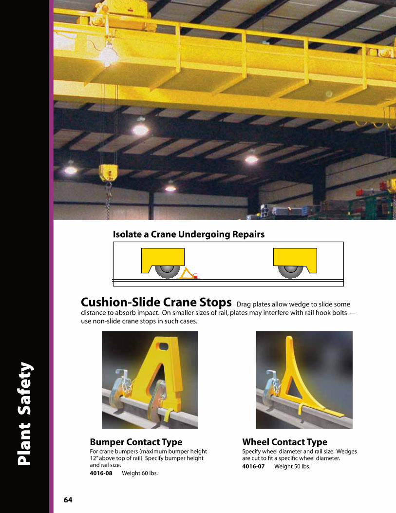
Cushion-Slide Crane Stops
Isolate a Crane Undergoing Repairs
Bumper Contact TypeFor crane bumpers (maximum bumper height 12” above top of rail) Specify bumper height and rail size. 4016-08 Weight 60 lbs.
Wheel Contact TypeSpecify wheel diameter and rail size. Wedges are cut to fit a specific wheel diameter. 4016-07 Weight 50 lbs.
Drag plates allow wedge to slide somedistance to absorb impact. On smaller sizes of rail, plates may interfere with rail hook bolts — use non-slide crane stops in such cases.
64
Plan
t Sa
fety

Protect Workers from Crane Overrun
Non-Slide Crane Stops Wedge dogs lock wedge to rail head and do notinterfere with rail hook bolts. On impact, stops may slide minimally. Tighten bolts frequently.
Wheel Contact TypeSpecify wheel diameter and rail size 4016-20 Weight 50 lbs.
Bumper Contact TypeFor crane bumpers (maximum bumper height 12” above top of rail). Specify bumper height and rail size.4016-21 Weight 60 lbs.
For all crane stops:•Useinpairs•Alignstops•Donotuseatendofcranerun•Allow ample distance between crane stops and the object to be protected.
65

Walkover Hose Bridge
Two-piece bridge snaps together to create a ramp 70” long x 24” wide x 6.75” high.
Holes in base of Bridge accept two 3”, two 4” and two 5” hoses/pipes.
Yellow base with non-slip grit walking surface. Carbide treated surface provides sure footing.
Shipped in two pieces, 70 pounds each.
4124-502
Flashing solar lights where you need themWho wants to replace and dispose of batteries? 360° solar light flashes 60 times per minute. Brilliant 6 LED light vis-ible for a mile. Solar battery operates 8 consecutive nights without recharging.
4015-334015-34
magneticbolting
AMBER 4015-35magnetic4015-57bolting
Bolt-on bracket
Magnetic bracket
Fully recharges with 2 sunny hours or 8 cloudy hours. External on-off push button conserves battery. Gravity switch disconnects light when light is turned to 45° or greater. Aluminum bracket with or without rare earth magnet permits a variety of mounting possibilities on any steel surface.
Weight with bracket, 5 lbs.Plan
t Sa
fety
RED
General Purpose Impact Sockets
Wide range of sizes, 3/4” and 1” square drive, deep and standard depth, hex and 8-point.
See website for sizing and pricing.
www.aldonco.com/sockets
Fire Hydrant Marker FlagFlexible 6 ft. fiberglass pole with red/white molded flag.4124-323
Pocket Lights
Small enough to slip into your pocket (32 in. wide). Brilliant 4 LED light visible up to 2 miles. Magnet base and belt clip. Uses two AA batteries. 4115-115 Red 4115-114 Blue 4115-117 Amber
CLEAR4015-58magnetic4015-59bolting
66

4124-212Barrel Length: 48” Weight: 4 lbs.
4124-213Barrel Length: 36” Weight: 4 lbs.4124-214Barrel Length: 60” Weight: 5 lbs.
Air BroomBetter than a push broom. Clean up dry spillage and unclog hopper chutes with a jet of high pressure air. Air Broom delivers 13.5 lbs. of thrust, with 100 PSI inlet pres-sure used. Dead man trigger protects worker. Handle accepts 3/4 in. male NPT pipe thread connections.
In winter, blow snow from track and switches. Better than a broom.
Poly Wall and Tank ScraperFiberglass pole handle extends to 24 ft. Polyethylene paddle has a 10 in. wide blade. Useful for scraping down bin walls inside covered hopper cars.
Paddle 4124-109 Wt. 2 lbs.Pole 4124-108 Wt. 6 lbs.
The heat-treated aluminum scraper paddle is 5 in. wide with a chisel edge. Six foot long pole extensions snap together to give the worker a long reach into a tank or bin.
Aluminum Tank and Wall Scraper
Paddle 4023-03 Wt. 2 lbs.Pole 4023-04 Wt. 2 lbs.
ALDON welded aluminum shovels are rust proof and durable, and are 40 percent lighter than steel blade shovels. Aluminum Shovels feature heat-treated aluminum blades, with a choice of 5-3/4” or 9-1/4” blade widths, and hickory handles comfort fitted with styrene grips.
Key Description Part No. Wt. Lbs.
1 Aluminum Shovel (5w in. blade) 4023-01 2.6
2 Aluminum Shovel (94 in. blade) 4023-02 3.5
3 All Aluminum Shovel (94 in. blade) 4023-42 3
Aluminum Shovels
3
12
67
Inlet Pressure 100 PSI Thrust (lbs.) 13.5 Flow (SCFM) 140
Do Not Exceed 120 PSI Inlet Pressure
Hanging Tool TrayA convenient place to keep small tools when working on the roofs of tank cars and hopper cars. Tray legs fit up to 2” diameter railings on landing platforms and gangways. Welded aluminum with durable yellow powder coat finish. drain holes in each corner.4024-280 Tray: 24” x 8” x 2-3/4”
Legs: 22” highWeight 6 lbs.
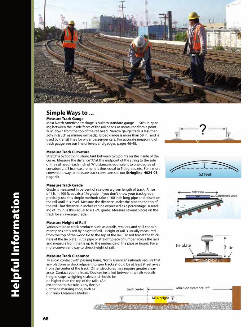
Hel
pful
Info
rmat
ion
Simple Ways to ...Measure Track GaugeMost North American trackage is built to standard gauge — 56½ in. spac-ing between the inside faces of the rail heads, as measured from a point s in. down from the top of the rail head. Narrow gauge track is less than 56½ in. (such as mining railroads). Broad gauge is more than 58 in. , and is used by transit lines for wider passenger cars. For accurate measuring of track gauge, see our line of levels and gauges, pages 46-48.
Measure Track CurvatureStretch a 62 foot long string taut between two points on the inside of the curve. Measure the distance “A” at the midpoint of the string to the side of the rail head. Each inch of “A” distance is equivalent to one degree of curvature ... a 5 in. measurement is thus equal to 5 degrees, etc. For a more convenient way to measure track curvature, see our Stringline 4024-03, page 49.
Measure Track GradeGrade is measured in percent of rise over a given length of track. A rise of 1 ft. in 100 ft. equals a 1% grade. If you don’t know your track grade precisely, use this simple method: take a 100 inch long pipe and raise it on the rail until it is level. Measure the distance under the pipe to the top of the rail. That distance in inches can be expressed as a percentage. A read-ing of 1½ in. is thus equal to a 1½% grade. Measure several places on the track for an average grade.
Measure Height of RailVarious railroad track products such as derails, rerailers, and spill contain-ment pans are sized by height of rail. Height of rail is usually measured from the top of the wood tie to the top of the rail. Do not forget the thick-ness of the tie plate. Put a pipe or straight piece of lumber across the rails and measure from the tie up to the underside of the pipe or board. For a more convenient way to check height of rail.
Measure Track ClearanceTo avoid contact with passing trains, North American railroads require that any platform or dock adjacent to spur tracks should be at least 9 feet away from the center of the track. Other structures may require greater clear-ance. Contact your railroad. Devices installed between the rails (derails, hinged stops, weighing scales, etc.) should beno higher than the top of the rails. (Anexception to this rule is any flexibleurethane marking cone, such asour Track Clearance Marker.)
tie plate tie
62 feet
track center Min. side clearance, 9 ft.
Max. height
68

69
OSHA Regulations
Single or Multiple Crane Operations1910.179(e) ... (ii) Stops shall be fastened to resist forces applied when contacted. (iii) A stop engaging the tread of the wheel shall
be of a height at least equal to the radius of the wheel.
(e) Where other cranes are in operation on the same runway, rail stops or other suitable means shall be provided to prevent interference with the idle crane
Loading & Unloading Semi-Trailers1910.178(k) (1) The brakes of highway trucks shall be set and wheel chocks
placed under the rear wheels to prevent the trucks from rolling while they are boarded with powered industrial trucks.
(3) Fixed jacks may be necessary to support a semitrailer and pre-vent upending during the loading or unloading when the trailer is not coupled to a tractor.
1910.178(m) ... (7) Brakes shall be set and wheel blocks shall be in
place to prevent movement of trucks, trailers, or railroad cars while loading or unloading. Fixed jacks may be necessary to support a semitrailer during loading or unloading when the trailer is not coupled to a tractor.
1910.111(f) ... (9) Chock blocks. At least two chock blocks shall be
provided. These blocks shall be placed to pre-vent rolling of the vehicle whenever it is parked during loading and unloading operations.
1910.261(c) ... (7) Handling pulp chips from trucks and trailers. i) All trucks and
trailers shall be securely fastened in place and all employees in the clear before dumping is started.
Signs & Lights1910.261(c) ... (9) Traffic warning signs or signals. The blue flag policy shall be
used to mark stationary cars day and night. This policy shall include marking the track in advance of the spotted cars (flag for daytime, light for darkness).
(ii) After cars are spotted for loading or unloading, warning flags or signs shall be placed in the center of the track at least 50 feet away from the cars and a derail set to protect workmen in the car.
Loading Tank Cars1910.111(b) ... (iii) Caution signs shall be so
placed on the track or car as to give necessary warning to persons approaching the car from open end or ends of siding and shall be left up until after the car is unloaded and disconnected from discharge connections. Signs shall be of metal or other suitable material, at least 12 by 15 inches in size and bear the words ‘’STOP-Tank Car Connected” or ‘’STOP- Men at Work” the word, “STOP,’ being in letters at least 4 inches high and the other words in letters at least 2 inches high.
(iv) The track of a tank car siding shall be substantially level.
(v) Brakes shall be set and wheels blocked on all cars being unloaded.
1910.110(b)(15) ... (iii) While cars are on sidetrack for loading or
unloading, the wheels at both ends shall be blocked on the rails.
Loading Pulp and Paper Cars1910.261(c) ... (4) Handling pulpwood from flatcars and all other railway cars. (V) Flatcars and all other cars shall be chocked during unloading.
Where equipment is not provided with hand brakes, rail damp-ing chocks shall be used.
(vi) A derail shall be used to prevent move-ment of other rail equipment into cars where persons are working.
Loading & Unloading Box Cars 1910.178(m)(6) as amended by OSHA Program Directive #100-63
(10/78) ... When a powered industrial truck is used to open freight car doors, and the truck is using an attached device specifically designed to open car doors, the violation of that part of 29 CFR 191 0.178(m)(6) shall be considered “de minimus,” when the following requirements have been met: a. The design of the door opening device shall require the force
applied by the device to the door to be in a direction parallel with the door travel.
b. The operator is trained in the use of the door opening device and keeps the operation in full view.
c. Employees, other than the operator, stand clear while the door is being moved.
Aldon® products to use: Wheel Chocks pages 20, 21, Derails pages 12-15, Car Blocks page 22
Spankysays, “You can never
be too safe”
Aldon® products to use: Blue Flag Signs page 17 and 29, Lights pages 16-17 and 30-31
Aldon® products to use: Easy-Slide or Aldor pages 38-39
Aldon® products to use: Crane Stopspages 64-65
Aldon® products to use: Wheel Blockspages 62-63and Trailer Stabilizing Jackspage 60
Aldon® products to use: Wheel Chocks pages 20-21. Blue Flag Signs pages 17 and 29, Car Blocks page 22, Derails pages 12-15
Aldon® products to use: Wheel Chocks pages 20-21. Blue Flag Signs pages 17 and 29, Car Blocks page 22, Derails pages 12-15
Freight Cars in General1910.178(k) (2) Wheel stops or other recognized positive protection shall be
provided to prevent railroad cars from moving during loading or unloading operations.
(4) Positive protection shall be provided to prevent railroad cars from being moved while dock boards or bridge plates are in position.
1910.178(m) ... (7) Brakes shall be set and wheel blocks shall
be in place to prevent movement of trucks, trailers, or railroad cars while loading or unloading.
1910.30(a) ... (5) Positive protection shall be provided to prevent railroad cars
from being moved while dock boards or bridge plates are in position.
1910.176 ... (f ) Rolling railroad cars. Derail and/or bumper blocks shall be pro-
vided on spur railroad tracks where a rolling car could contact other cars being worked, enter a building, work or traffic area.

Identifying RailMany sizes of rail have been produced in the last 100 years. It is important to identify the specific pound weight per yard and rail section designation (section is the shape of the rail when viewed on its end). Stamped at intervals on the web of the rail are letters and numbers which identify the weight per yard and rail section. Consult the chart here for an exact rail size designation.
Rail Identification Chart
data provided courtesy of L.B. Foster Company
Rails designated by ASCE (especially 12 lb. to 85 lb.) are likely to be used as crane rail. The heavier rails shown are for railroad use.
70
RAIL DIMENSIONSHT HeightBW WidthofBaseHW WidthofHeadW Web(atcenterpoint)HD DepthofHedFD FishingBD DepthofBaseE BoltHoleElevation
WEB
BASE
HEAD (or ball)

A video clip is worth a thousand words. Check out our mini-website for informative short videos on key rail safety products
SwitchCube® Indicator1 minute
Tank Car Pry Bar1 minute
How to Turn, and Replace Aldon Steel Wheel Chock
Spurs2 minutes
High SecuritySwitch Point Lock
30 seconds
Pop-Up DerailSign Holder
1 minute
Pry Bar forSwing Gate Hopper Cars
30 seconds
Hatch Key® Pry Barsfor Covered Hopper Cars
40 seconds
Mouse TrapSign Holder30 seconds
Sabertooth® Portable Derail
3 minutes
Magnetic Sign Holder for Flush or Exposed Rail
20 seconds
Tiesnugger1 minute
Aldor1 minute
Roadmaster1 minute
Easy-Slide2 minutes

BENDERS, RAILHeavy Rail .................................................................... 52Mine Rail ...................................................................... 52
BROOMSAir Broom .............................................................. 36, 67Track & Switch Broom ..................................... 51, 58
CAR LOADING/UNLOADINGAir Brooms ............................................................ 36, 67Brake Stick .................................................................... 21Car Shakers/Vibrators .............................................. 37Coupler Alignment Tool ......................................... 43Hose Cradle ................................................................. 40Hose & Pipe Bridge ................................................... 66
OPENERSBoxcar Door Openers ........................................ 38-39Hopper Car Door Openers ....................... 32-33, 37Tank Cars ...................................................................... 40
Scrapers .................................................................. 36, 67Spill Control .......................................................... 36-37
CAR SHAKERS & ACCESSORIES ............................. 37CARTS/DOLLIES ........................................................... 51CHOCKS and BLOCKS
RAIL CAR Specialty Chocks .................................................. 22 9-Lives Wheel Wedge .................................... 22 Car Stopper Chock .......................................... 22 Double Tension ................................................ 22
Tank Car Wheel Block ......................................... 22 Standard Chocks .................................................. 20 Stay-Clear/High-Vis ............................................. 20 Whack ‘Em .............................................................. 21
TRUCK With Handles ................................................... 62-63 Without Handles ............................................ 62-63Clearance Markers, Exposed & Flush Rail .......... 9Delineator Tape ..................................................... 29, 59DERAILS .................................................................... 10-15
ACCESSORIES Flashing Lights ...................................................... 13 Lifting Lever ........................................................... 13 “MoonSign” ............................................................ 13 Padlocks .................................................................. 13
Replacement 10” Sign Plates ........................... 13
DERAILS (continued)Hinged W/Manual-Lift Sign .................................. 12Hinged W/Pop-Up Sign ......................................... 12 Retractable ................................................................ 14Portable ...................................................................... 15
Dockboards.................................................................... 39Fall Protection (Rail Anchor) .................................. 51Gauge Rods ............................................................... 6, 51HAZMAT/SPILL CONTROL ................................. 36-37JACKS
Railcar Stabilizers ...................................................... 25Trailer Stabilizers ....................................................... 60Track Jacks
Quick-Trip Hydraulic ............................................................ 55 Manual ................................................................ 55 Ratchet Lever .................................................... 55LEVELS/GAUGES
Gauge Spreader ........................................................ 49Rolling Gauge Readers ..................................... 46-47Tie Gauge..................................................................... 48Track Levels & Gauges ............................................. 48
LIGHTSBattery Powered.................................................. 30-31
Lanterns ....................................................................... 30Personal Safety Lights ............................................. 30Solar Powered ............................................................ 30
Motion Sensing Signal ............................................. 31OPENERS and PRYBARS, RAILCAR
Boxcar Door Openers ........................................ 38-39Hopper Car Door Openers Covered Hopper Cars
Electric ................................................................ 35 Manual .......................................................... 32-33 Pneumatic .................................................... 34-35
Flat CarsFlat Bed Winch Tension Bar .......................... web
Open Top Hopper Cars Pry Bars .................................................................... 33
Tank CarsTank Car Pry Bar .................................................... 40Tank Car Socket Wrenches ................................ 42Tank Car Sockets .................................................. 42
Inde
xIndex
Our website www.aldonco.com contains more products than our catalog can carry. Items which appear only online, are marked below as “web”. If there is some railroad safety or maintenance
product that you do not see here, contact us and we will try to find it for you.
72

Spark-Proof Bronze ............................................. 42 Steel ........................................................................... 42
Track Bolt ..................................................................... 51STOPS
Crane Stops Cushion Slide ......................................................... 64 Non-Slide ................................................................ 65
Railcar Stops Bumping Posts ...................................................... 24
Hinged Locking Stops ........................................ 24 Self-Tightening Stops ......................................... 24
Severe Duty Stops ............................................... 24SWITCH POINT SAFETY and MAINTENANCE
Graphite Grease & Applicators............................. 51“Switch Cube” ® Indicator ...................................... 4-6 Switch Handle, “Easy Throw” .....................................6 Switch Point Lock ........................................................ 8Switch Point Protector ............................................... 8Switch Targets ............................................................... 7
TANK CAR SAFETYHose & Pipe Bridge ................................................... 66Hose Cradle ................................................................. 40Manway Cover ........................................................... 41Manway Lid Sockets and Wrenches .................... 42Pry Bar ........................................................................... 40Safety Gate .................................................................. 41Wheel Block ................................................................ 41
TONGSRail & Timber .............................................................. 53
TOOLSMeasuring Tools
Digital Measuring Pole ................................... webRolling Distance Counter .................................. 49
Stringline ................................................................ 49Tape Measure, Track Inspector ........................ 48
Track Tools Ballast Handling ................................................... 56 Rail Handling ......................................................... 57 Spike Handling ..................................................... 57
Tie & Timber Handling ....................................... 56WRENCHES
“Gate Master” (Gate Opener) ................................ 32Tank Car Socket Wrench ......................................... 42Track Bolt Ratchet Wrench .................................... 51Track Wrenches
Double-end ........................................................... 57 Ratchet Action ...................................................... 57 Single-end .............................................................. 57
PADLOCKS ........................................................................ 8PERSONAL SAFETY
Arm/Leg Bands ...................................................... webPersonal Safety Lights ............................................. 30Safety Vests ............................................................. web
RAIL CAR MOVER, PULLERManual Car Mover .................................................... 43Car Pulling Accessories (rope, hook) .................. 43
RAIL ALIGNMENTRail Pull (gauge restoring tool) ............................ 54Rail Splint ...................................................................... 54Rail Alignment Cradle .............................................. 55Rail Puller/Expander ............................................ web
REPAIR SHOP, CAR/LOCOMOTIVEAir Brake Tools ............................................................ 59 Delineator Tapes ................................................ 29, 59Freight Car Stand, Fixed Height ........................... 59Lifting Tong ................................................................. 58Locomotive Drawbar Strap ............................... webMagnetic Signs .......................................................... 58Railcar Stabilizing Jack ............................................ 25
Slings Drawbar Sling ........................................................ 58 Traction Motor ....................................................... 59 Wheel Sling ............................................................ 58
Traction Motor Lifting Dolly .................................. 59RERAILERS
“Big Red” Two-Way Rerailers ................................. 44“Burlington” Style Two-Way Rerailers ................ 44“McCarty” Two-Way Freight Car Rerailers ........ 45Permanent Rerailers (Diamond) .......................... 45Straddle-Type One-Way Rerailers ....................... 44
SIGNSNylon Flags & Holders ............................................. 29Sign Holders ......................................................... 16-17Sign Plates
Highway/Rail Crossing Signs ........................... 27Industrial Switching Signs ............................... 5-7OSHA Blue Flag ..................................................... 17
Railyard Signs .................................................. 26-28 Tie Mounted .............................................................7SKIDS/SKATES
Chocking Skid for Flush Rail ................................. 23Industrial Service ...................................................... 23Railroad Service ......................................................... 23
SOCKETS and WRENCHESImpact (General Purpose) ...................................... 66Tank Car Manway Lid ............................................... 42
73

Cover created by Sean Michael Lambrecht
1904
1904ALDON CO.ESTABLISHED
1914
1916US RAIL MILEAGE
PEAKS AT 254,000 MILES
1917U.S. ENTERS
WORLD WAR IRAILWAYSNATIONALIZED
1920RAILWAY EMPLOYMENTPEAKS AT 2 MILLION
1924
1929THE GREAT
DEPRESSION BEGINS
1934
1934BURLINGTON ZEPHYRDIESEL STREAMLINER
INTRODUCED
1937FIRST CONTINUOUSRIBBON RAIL LAID
1944 1954
1941U.S. ENTERSWWII
1948ALCO BUILDS LAST
STEAM LOCOMOTIVE
1954ICC
CLARIFIESLEGALITY
OFTOFC
SERVICE
1914U.S. COMPLETES
ALASKA RAILROAD
Jamieson Equipment Company | 800.875.0280 toll free | [email protected]
![Forschungsberichte - iwb.mw.tum.de · 1994, SELIGER 1994, WARNECKE & SCHRAFT 1984]. Im folgenden sollen einige der möglichen Rationalisierungsansätze vorgestellt werden (Abbildung](https://img.dokumen.tips/doc/110x75/5e1eb56cdba17c7f5f4e00f1/forschungsberichte-iwbmwtumde-1994-seliger-1994-warnecke-schraft-1984.jpg)
![Case Law Update - Murray Jamieson · A. Mohan Requirements R. v. Mohan, [1994] 2 S.C.R. 9 The Supreme Court of Canada decision in R. v. Mohan, [1994] 2 S.C.R. 9 provides the foundation](https://img.dokumen.tips/doc/110x75/5f05a3857e708231d413f5a4/case-law-update-murray-a-mohan-requirements-r-v-mohan-1994-2-scr-9-the.jpg)