Embed Size (px)
Citation preview
o .
!i:>
1979024988
https://ntrs.nasa.gov/search.jsp?R=19790024988 2018-08-27T12:20:35+00:00Z
i
ERRATAr ,
NASA Technical Memorandum X-3250
FLIGHT-DETERMINED LIFT AND DRAG CHARACTERISTICS OFAN F-8 AIRPLANE MODIFIED WITH A SUPERCRITICAL WING
WITH COMPARISONS TO WIND-TUNNEL RESULTS
Jon S. Pyle and Louis L. SteersJune 1975
Page 1: The second paragraph should read as follows:
An F-8 airplane was chosen as the test-bed for the demonstration of the super-critical wing because of the supersonic eapability of the aircraft and the relative easewith which the wing on the F-8 airplane could be replaced. The aircraft also offereda unique opportunity to acquire reliable data near the sonic speed as well as through-out the transonic range for detailed comparisons of wind-tunnel and flight results.A series of wind-tunnel studies (refs. 5 and 6) was then conducted to establish arepresentative supereritical wing configuration for the F-8 airplane and to define
the performance, stability, and control characteristics of the test vehicle through-out a typical transport operating envelope.
Although the original intent of the program was proof of concept for the wing i' alone, it was subsequently found that the wing's characteristics could not be
readily isolated from those of the complete aircraft. Inconsistencies from suchsources as stiag interference, improper inlet flow, and differences in controleffectiveness were therefore unavoidably implicated in the verification of the Iwing concept as an integral part of the total aircraft. It is the intent of thisreport, however, to emphasize proof of concept rather than differences in test 1technique. A preliminary assessment of the wing based on early correlations
between flight and wind-tunnel data is given in reference 7. 1
Page 8: The second paragraph should read as follows: i
Two exit ducts wer_ used during the wind-tunnel model tests, both of whichwere wholly contained within the scaled mold lines of the airplane. The smaller :duct was used to provide additional side clearance for the model sting during theyaw tests. The second duct was used to simulate the ,nass flow ratios of theairplane and to determine the internal drag corrections for the wind-tunnelresults. All wind-tunnel results presented in this paper were obtained with thesecond _:_it duct and adjusted by means of the internal drag correction.
Page 9, paraffraph 1: The second sentence should read as follows:
For example, the corrections applied to the wind-tunnel data for a Mach numberof 0.95, a lift coefficient of 0.4, and the Reynolds number equivalent to an altitude /of 10.7 kilometers (35,000 feet) were as follows: y
?
1979024988-002
' ERRATA--Continued
Page 9: Paragraphs 2 and 3 should read as follows:
Transitionstripswere placed on the model wing at eitherof two locations,the. 5-percentor the 31-percentchord, depending on the Mach number of the test
(ref.9). The 5-percent locationwas used for subcriticalMach numbers (M = 0.90._ and below) to forcetransitionat a known locationbehind the wing leading edge.
The rearward positionwas used atthe criticalMach number conditionsto simulatefull-scaleboundary-layer trailing-edgedisplacementthicknesscharacteristics.For the rearward positiona correctionwas made toadjustthe wind-tunnel data to aconditionoffullyturbulentflow.
Alllossesfrom the inletto the exitofthe model were considered internaldragand were removed from the wind-tunnel results. As statedpreviously (INSTRUMEN-TATION section: Wind Tunnel), the base dr_g was alsoremoved from the wind-tunneldrag results. Therefore, the wind-tunnel drag resultspresented in thispaper representthe external,wetted surface area ofthe model.
Page 11: The followingparagraphs should be insertedbefore the sectionentitledMass flow.
The F-8 supercriticalwing airplanewas designed toprovide in-flightaero-dynamic characteristicsat sustainedtransonicspeeds. The flightand wind-tunneldrag results are compared in figures 14 to 23. _ ,
The wind-tunnel tests that were used for comparison purposes were si_nilar tothe tests an aircraft company might make to develop new configurations (that is,the model was sting mounted and the wings were rigid and designed for a particular
set of flight conditions (M = 0.99, CL = 0.4, q = 9.6 kN/m 2 (200 lb/ft2), h = 13.7 km
(45,000 ft)). The wind-tunnel drag results were adjusted to flight conditions asdiscussed in CORRECTIONS TO WIND-TUNNEL DATA. The compariso,,_ A thedrag polar results were made by removing the base drag from both the flight andwind-tunnel data rather than by adjusting the results for jet effects and stinginterference. No attempt was made to adjust the wind-tunnel results from therigid model to the flexible airplane.
Where possible, the individual drag components (such as base drag, boattaildrag, and mass flow ratio) that were measured in the flight tests were compared
, with those measured in the wind-tunnel tests.
Page 11: The first sentence of the last paragraph should read as follows:
. As might be expected for a wing designed for a particular trimmed cruise
! condition (M = 0.99, CL = 0.4, q = 9.6 kN/m 2 (200 lb/ft2)), there is a noticeable
, _ difference between the flight and wind-tunnel drag polar curvatures.
Page 12: The following sentence should be inserted at the end of paragraph 1:
A complete discussion of the wall interference effects is given in paper 9 ofreference 7.
1979024988-003

FLIGHT-DETERMINED LIFT AND DRAG CHARACTERISTICS OF AN
F-8 AIRPLANE MODIFIED WITH A SUPERCRITICAL WING WITH
COMPARISONS TO WIND-TUNNEL RESULTS
Jon S. Pyle and Louis L. SteersFlight Research Center
INTRODUCTION
A supercritical airfoil has been developed to increase the drag-rise Mach num-ber for a given lift coefficient or to increase the lift coefficient for separation onsetat a given Mach nu.'_ber (refs. 1 to 4). Wind-tunnel studies were conducted todetermine the feasibility of applying a supercritical airfoil to a transport configura-tion. As a result of the wind-tunnel studies, a wind-tunnel and flight test programwas initiated to verify the advantages of the supercritical wing with an existing air-plane.
A TF-SA airplane was chosen as a test-bed to demonstrate the supercriticaiwing concept. The supercritics] wing was adapted to this airplane's fuselage;henceforth, in this paper, this airplane is referred to as the F-8 supercritical wingairplave. Wind-tunnel atudies (refs. 5 and 6) were conducted to adapt the new
: wing to the test vehicle m_d to determine the vehicle's performance, stal)ility, andcontrol characteristics. F:ight tests were conducted to verify the characteristics
:_ predicted by the wind-tunLel studies and to determine the value of the supercriticalwing concept in a flight environment. Reference 7 is a preliminary report of the
_,. results obtained during these proof-of-concept flight tests.y
: These first flight tests were conducted with a nonoptimum area distribution.The area distribution of the basic configuration was not particulaz !y well suited tospeeds near Mach 1; therefore, the distribution was improved by ddding area-rule
_ fairings to the fuselage. This paper presents the lift and drag characteristics_ determined in flight for both configurations (with and without the area-rule fuselage -.
fairings) and compares the flight and wind-tunnel data for each case.
The flight results are for altitudes from 7.6 kilometers (25,000 feet) to 13.7 kilo-meters (45,000 feet) and for Mach numbers from 0.6 to 1.2.
- i I., ,__T22.2 ..... L_,_
1979024988-004
-. SYMBOLS
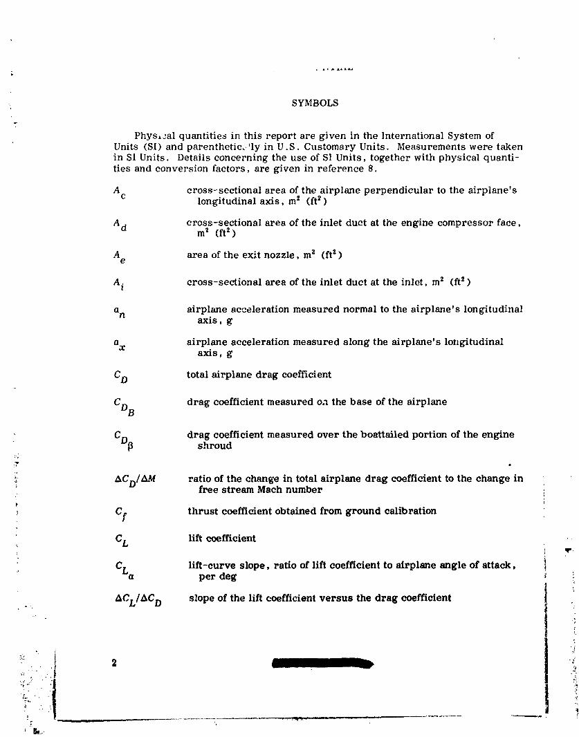
Phys,_al quantities in this report are given in the International System ofUnits (SI) and parenthetic. 'ly in U.S. Customary Units. Measurements were takenin SI Units. Details concerning the use of SI Units, together with physical quanti-ties and conversion factors, are given in reference 8.
A cross-sectional area of the airplane perpendicular to the airplane'sc longitudinalaxis,m s (ft_)
A d cross-sectional area of the inlet duct at the engine compressor face,m2 (ft 2 )
A area of the exit nozzle, mz (ft 2)e
A. cross-sectional area of the inlet duet at the inlet, ms (ft 2 )z
a airplane acceleration measured normal to the airplane's longitudinaln axis,g
a airplane acceleration measured along the airplane's longitudinalx axis, g
CD total airplane drag coefficient
CDB drag coefficient measured on the base of the airplane
CD[1 dragshroudCoefficientmeasured over the boattailed portion of the engine
ACDIAAf ratio of the change in total airplane drag coefficient to the change infree stream Math number
Cf thrust coefficient obtained from ground calibration
CL lift coefficient .-
lift-curve slope, ratio of lift coefficient to airplane angle of attack, i_ CLa per deg
ACL/AC D slope of the lift coefficient versus the drag coefficient
,)
1
I' BI__.,
] 979024988-005

ERRATA--Continued
,_" Page 13: The following paragraphs should be inserted before the CONCLUDINGREMARKS section:
Adjustments to _,ind.-tunnel drag and model to flight comparison.--Three majorcomponents of drag were defined for the wind-tunnel model and flight vehicle. Anaccounting for the differences in these drag components can then be made. This ,permits modeI-to-flight comparisons of drag coefficients with these three componentseliminated as contributors to any remaining differences in drag coefficient. Thefollowing table shows the adjustments made to the wind-tunnel data for flight condi-tions at a Mach number of 0.95, a lift coefficient of 0.4, and an altitude of 10.7 kilo-
meters (35,000 feet). (All quantities were added to the model value of CD.)
Adjustment to wind-tunnel
value of CD for configurationComponent adjusted with side fairings--
Off On
, Base drag 0.0024 0.0029
Boattail drag 0.0011 0.0013
Trim characteristics 0.0012 0.0014
: The resulting wind-tunnel drag values compared with the flight values are as ifollows: i'
4
• : CD for configuration '
_-_._ with side fairings--
! Off On
• | Adjusted wind-tunnel model 0.0323 0.0332
i _ Airplane 0.0348 0.0362 __i . ......
l This relationship between the full-scale flight and wind-tunnel model dragcoefflc:ents for 10.7 kilometers (35,000 feet) altitude is based upon a very completeset of flight-derived polars. Although the flight experience at an altitude of13. T kilometers (45,000 feet) for the same Math number was less comprehensive, ithe flight-to-model relationship was qualitatively similar. ,_
., The remaining differences between the wind-tunnel and flight-measured drag* values were probably due to the higher mass flow ratios in the wind-tunnel tests, ,_-
; differences m flexibility between the mcdel and the airplane, and probable differences ,,t in the pressures over the aft sloping fuselage surface forward of the instrumented _,] boattU ( erbody).
" !r
:!
1979024988-006

ERRATA--Concluded
Page 73: The symbols for the wind-tunnel data in fi_lre 14 should be identified asfollows:
" Wind Area-rule-_ Flight tunnel fuse_acjefairincjs/
.9 - a On• Off
!
.6 I I.8 .9 1.0
M
,.r
: Issue date: 8-2-77
-r
1979024988-007
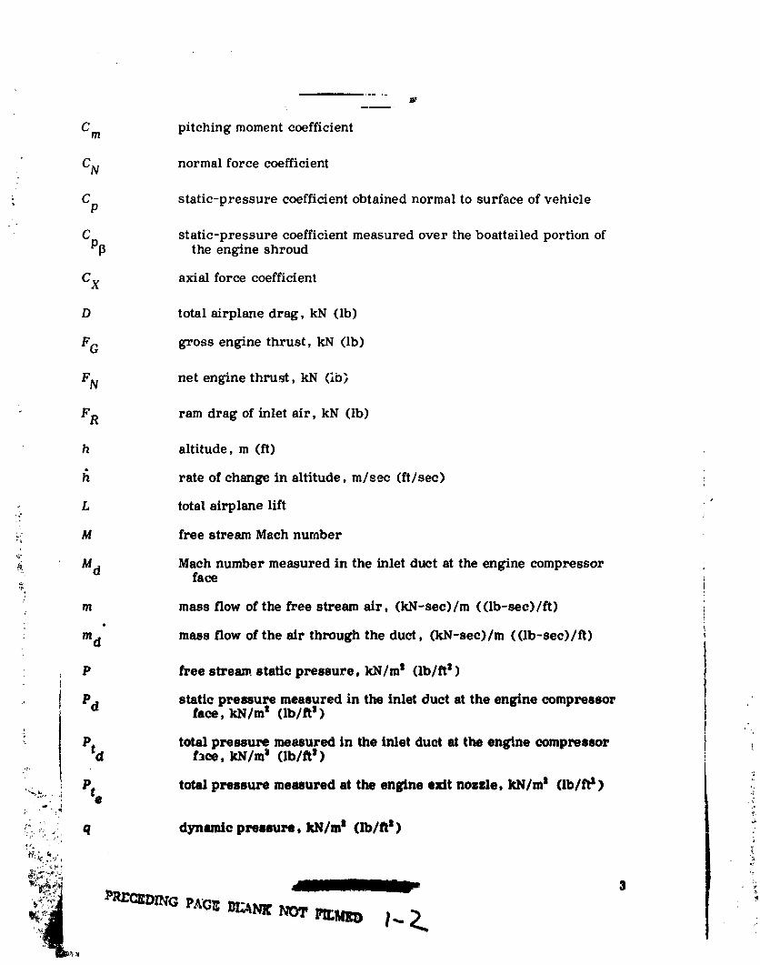
C m pitching moment coefficient
CN normal force coefficient
Cp static-pressure coefficient obtained normal to surface of vehicle
C static-pressure coefficient measured over the boattailed portion ofP_ the engine shroud
C X axial force coefficient
D total airplane drag, kN (lb)
FG gross engine thrust, kN (lb)
FN net engine thruM, kN (ib)
FR ram drag of inlet air, kN (lb)
h altitude, m (ft)
fl rate of change in altitude, m/see (t/see)
- L total airplane lift
:_ M free stream Mach number
M d Math number measured in the inlet duct at the engine compressorface
/
m mass flow of the free stream air, (kN-sec)/m ((Ib-see)/ft)
: md mass flow of the air through the duct, (kN-sec)/m ((lb-sec)/fl)
• P free stream, static pressure, kN/m s (lb/fl s)
' Pd static pressure measured in the inlet duct at the engine compressorface, kN/m s (lb/ft s)
-.- Ptd total pressure measured in the inlet duct at the engine compressorf_ee, kN/m s (lb/ft s)
,_._ ." Pie total pressure measured at the engine exit nozzle, kN/m s (lb/ft s ) _;:_
__.,,: q dynamic pressure, kN/m n (lb/fl n)
"1979024988-008

"_ R Reynolds number
S planform area ofthe supercriticalwing, m 2 (ft_)
T freestream temperature, °K (°R)
Td temperature ofthe airin the inletduct, °K (°R)
l_ rateof change in velocity,m/sec2 (ft/sec2)
W airplaneweight, kN (Ib)
x/! ratioof distancealong the airplane'slongitudinalaxis tothe totalairplanelength
a angle of attack,deg
&a correction to angle of attack for in-flight calibration, deg
AaB correctionto angle of attackfornose-boom bending during normalacceleration,deg
5 average deflection of horizontal stabilizers, dege
y ratio of specific heats
0 circumferential location of boattail orifices on the aft portion of theairplane fuselage, deg
VEHICLE DESCRIPTION
o,. Flight Vehicle.%
The TF-8A airp]ane provided the empennage, fuselage, and propulsion sys-tems for the supercritical wing flight tests (figs. l(a) and l(b)). The TF-SA air-plane is a single-place interceptor powered by a J57-P4 turbojet engine with _,fter-burner capability. Air is supplied to the engine by means of a main duct throughthe fuselage. The duct inlet is approximately 0.79 meter (2.6 feet) behind the apexof the airplane's nose cone.
- In its original configuration the airplane had a variable incidence, high-, mounted wing that was easy to replace with the supercritical wing. A three-view
drawing of the F-8 supercriticai wing airplane is presented in figure 1(c). Thehorizontal and vertical stabilizers were not chonged for the test program.
The cross-sectional area distribution of the F-8 supercritleal wing airplane isshown in figure 2. The distribution for the first flight tests (without ares-rule
t
i
4
1979024988-009
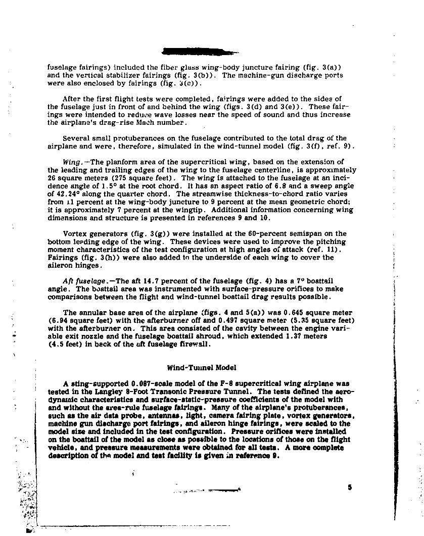
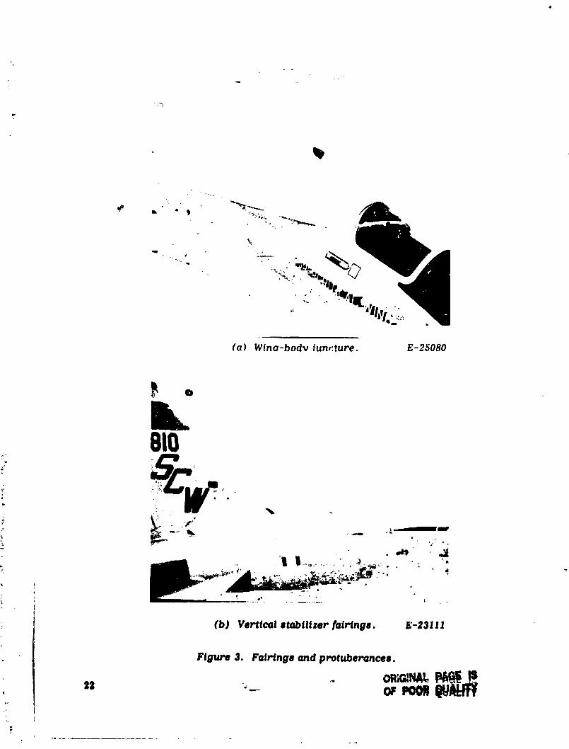
fuselage fairings) included the fiber glass wing-body juncture fairing (fig. 3(a))and the vertical stabilizer fairings (fig. 3(b)). The machine-gun discharge ports
: were also enclosed by fairings (fig. 3 (c)).
• After the first flight tests were completed, fa_rings were added to the sides ofthe fuselage just in front of and behind the wing (figs. 3 (d) and 3 (e)). These fair-ings were intended to reduce wave losses near the speed of sound and thus increasethe airplane's drag-rise Mach number.
Several small protuberances on the fuselage contributed to the total drag of theairplane and were, therefore, simulated in the wind-tunnel model (fig. 3(f), ref. 9).
Wing.--The planform area of the supercritical wing, based on the extens,:on ofthe leading and trailing edges of the wing to the fuselage centerline, is approximately26 square meters (275 square feet). The wing is attached to the fuselage at an inci-dence angle of 1.5 ° at the root chord. It has an aspect ratio of 6.8 and a sweep angleof 42.24 ° along the quarter chord. The streamwise thickness-to-chord ratio variesfrom 11 percent at the wing-body juncture to 9 percent at the mean geometric chord;it is approximately 7 percent at the wing'tip. Additional information concerning wingdimensions and structure is presented in references 9 and 10.
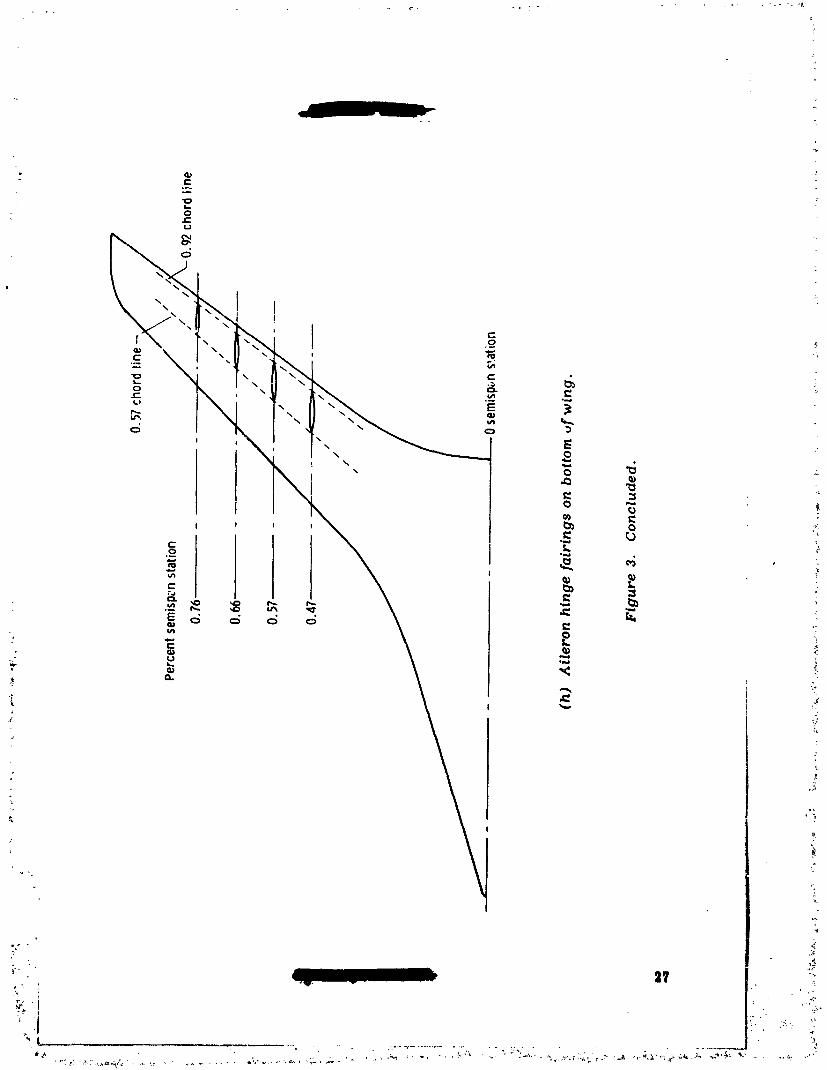
Vortex generators (fig. 3 (g)) were installed at the 60-percent semispan on thebottom lepding edge of the wing. These devices were used to improve the pitchingmoment characteristics of the test configuration at high angles of attack (ref. 11).Fairings (fig. 3(h)) were also added to the underside of each wing to cover the !aileron hinges.
Aft fuselage.--The aft 14.7 percent of the fuselage (fig. 4) has a 7° boattailangle. The boattail area was instrumented with surface-pressure orifices to makecomparisons between the flight and wind-tunnel boattail drag results possible.
The annular base area of the airplane (figs. 4 and 5 (a)) was 0.645 square meter(6.94 square feet) with the afterburner off and 0.497 square meter (5.35 square feet)
:'. with the afterburner on. This area consisted of the eaviW between the engine carl-- able exit nozzle and the fuselage boattail shroud, which extended 1.37 meters' (4.5 feet) in beck of the aft fuselage firewell.¥
Wind-Tmmel Model
A sting-supported 0.087-scale model of the F-8 supereritical wing airplane wastested in the Langley S-Foot Transonic Pressure Tunnel. The tests defined the aero-dynmnic characteristics and surface-static-pressure coefficients of the model with
i and without the a_ea-rule fuselage fairtngs. Many of the airplane's protuberances,such as the ah, data probe, antennas, light, camera fairing plate, vortex generators,machine gun discharge port fairings, and aileron hinge fairings, were scaled to themodel size and included in the test configuration. Pressure orifices were installed -
-:,, on the bosttail of the model as close as possible to the locations of those on the flight'_ - vehicle, and pressure measurements were obtained for all testa. A mote oomplete
desm'iption of tb_ model and test faaility is g/yen m z_d'e_noo 0.
11_2- " "
]979024988-0]0
INSTRUMENTATION
Flight
Flight lift and drag were calculated from measurements made with onb,_instrumentation. All measurements were recorded on board with magnetJr apeand telemetered to a ground station by a pulse code modulation system. . ,m pro-cedures and equations used to determine the angle of attack, thrust, an(i drag fromthe flight test measu.-_ments are presented in the appendix.
Air dataprobe.--StandardNACA flow directionsensors (ref.12) and a M0ch-number-compensated pitot-staticprobe designed forthisconfigurationwere mountedon the nose beam (ref.13). The impact-pressure and compensated static-pressureorificeswere 2.09 meters (6.85feet)and 2.04 meters (6.68feet)in frontof thevehicle'snest. "'espectively.Ang]e ofattackand angle of sideslipwere measuredby floatingvanes thatwere 1.42meters (4.67feet)and 1.32 meters (4.32feet}infrontofthe vehicle'snose, respectively.A temperature probe was mounted oppositethe angle-of--attackvane tomeasure freestream totaltemperature.
In-flightcalibrationsofangle of attackindicatedthatsome interferencewasoccurring between the angle-of-sideslipand angle-of-attackvanes at Math numbersnear I.0. The interferencewas eliminatedby removing the sideslipvane and shaft.Allflightresultspresented in thispaper were obtainedafterthe angle-of-sideslipvane and shaftwere removed.
Liftand drag.--An accelerometerpackage thatcontainedtwo longitudinalaceel-erometers (_+0.25gand +l.ag), two normal aceelerometers(-4g to Ig and -3g to 6g),one transverse accelerometer(_+Ig).and a three-axisgyro was mounted on the maincenterlinekeelbeam 9.6 meters (31.5feet)aftof the fuselagenose. The outputsofthe +0.25g longitudinalaecelerometerand the -3g to6g normal accelerometerwerefilteredto exclude frequenciesgreaterthan I0 cyclesper second and correctedtothe airplanecenter of gravity,zero angular velocity,and zero angular acceleration.The resultingaccelerationswere used tocalculatethe normal and axialforces
7 exerted on the airplane. The total weight of the airplane at any time during a flightwas calculated from recordings of fuel quantity and preflight gross weight.
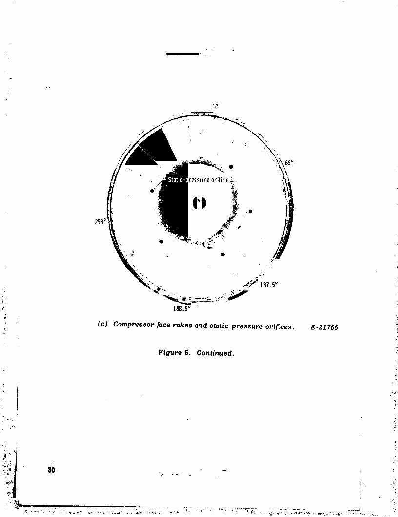
• Thrust.--The momentum of the air in the inlet as it entered the engine compres-sor face was calculated from measurements of total and static pressure obtained with
_" rakes and static orifices (figs. 5(b) and 5(c)). The total-pressure measurement atthe engine compressor face was obtained with five radial rakes, each of which con-
_ tained five manifolded pressure probes. The pressure measurements from each rake(fig. 5(b)) were averaged to obtain the cross-sectionai total pressure at the compres- -,sot face. In the same way, the static-pressure orifices around the pump housingof the engine (fig. 5 (c)) and the engine duct were averaged to obtain _he ambientpressure at the compressor face. All momentum losses in front of the compressorface were considered to be part of the drag of the fuselage.
The momentum of the air leaving the engine was measured by an air-cooledpitot probe mounted in the engine exhaust (figs. 5(a) and 5(d)). This measurement
a ,. •i
!
I
}
] 979024988-0] ]
} procedure has b,_enverifiedIn experiments with a s._milarjetengine mounted in ahigh performance airplane(refs.14 and 15). The coolingairforthe exhaust probe
- was obtainedfrom the laststageofthe engine compressor.
, Boattailand base pressures.--A seriesof surface-pressureorificeswas in-stalledatcircumferentialstationsof 8°, 46°, 135°,and 180° along the righthalfofthe boattailedportionofthe fuselage(fig.4). The orificeswere in _ixrings aroundthe fuselagethetwere between 94.7 percent and 99.6 percent ofthe fuselagelength
Base pressures were measured atfour circumferentiallocations(0°, 90°, 180°,and 270°) insidethebase cavityof the fuselage. Both theboattaiiand base pressuremeasurements were obtainedwith a scanivalvetransducer in a rear sectionofthe
fuselage.
Pressures along area-rulefuselagefairings.--Theairplanearea-rL,lefuselagefairingswere notoriginallyequipped with the orificesand internaltubing necessaryforpl-essuremeasurements. Therefo,'e,flexiblevinyl tubing with staticorifices(figs.6(a) to 6(c)) was attachedtothe airplane'sarea-,'ulefuselagefairingsinouch a way thatflightpressure measurements could be compared with existingwind-tunnel data. The tubing was fairedto the fuselagesurfacewith an aircraftsealer. Orificeswere cut in the tubing atapproximately the same locationsas usedin the wind-tunnel tests. Some orificetubes were installedoffthe centerlineof
the fairingto determine the effectsof attitudeand cross-flowinterference.Pressuremeasurements were obtainedwith existinginternalinstrumentation.
Wind Tunnel
Force and moment data (ref. 9) were obtained in the Langley 8-Foot TransonicPressure Tunnel with a strain-gage balance mounted in the fuselage cavity of a0.087-scale model of the airplane. Pressures at the orifices along the area-rulefuselage fairings and on the boattailed portion of the fuselage were measured with adifferential-pressure scanning-valve mounted in the model's nose section. Staticpressures were measured in the balance chamber and on the base plane of the modelto determine the base drag. When the wind-tunnel results were analyzed, the basepressures were adjusted to ambient conditions. Thus. all the drag results presented
_ in reference 9 represent wind-tunnel model drag withe'at base drag,
TEST CONDITIONS
Flight
, The flight data presented in this paper were obtained from long-period accel- °erating turns and quasi-stabilized, constant altitude runs at altitudes of 7.6 kilo-meters (25,000 feet), 19.7 kilGmeters (35,000 feet), and 13.7 kilometers (45,000 feet), tThe Mach number range of the testa varied from 0.8 to 1.2. Reynolds number, basedon the wing mean geometric chord, varied from 0.8 × 10T to 2.3 × 10T. The center-of-gravity position for the test_, was apprc.ximately 25 percent of the wing mean geo-metric chord.
v
'. , --m..mms.jUp_, _
i
1979024988-012

_w
: Wind Tunnelp
_. Wind-tunnel measurements (ref. 9) were made over a lVlaeh number range from0.25 to 1.0. Angle of attack varied from -5 ° to 12°; angle of sideslip was 0°. TheReynolds numbers of the wind-tunnel tests ,_,aried from 1.8 × 10⁶ to 3.0 × l0 s basedon the wing mean geometric chord of the wind-tunnel model.
The internal flow through the model was constricted by the sting support used tomo_,nt the model in the Langley 8-Foo: Transonic Wind Tunnel. Therefore, to simu-late the internal masz flow ratios that were expected with the airplane, two exit _.uetswere used (luring the wind-tunnel model tests. Both duets were wholly containedwithin the sealed base lines of the airplane. Wind-tunnel data for the two duets werecompared to obtain an adjustment for 'is increase in internal drag due to the stingsupport (_lef. 6). This adjustment was made to all the wind-tunnel results used inthis paper. -
FLIGHT DATA ACCURACY
The parameters that contributed to random error in the flight results are listedin _he following table. The table is based on data obtained for a Mach number of
: 0.97, a lift coefficient of 0.4, and an altitude of 13.7 !:J" _eters (45,000 feel).
Error in Error inError inParameter measurement CL, percent CD. percent
ii ii i n , i ii _ i i
Weight +4.4 kN (±100 ib) 0.4 ....
Dynamic pressure +0.06 kN/m _ (+_1.O lb/ft _ ) 0.6 0.6
4 Net thrust +0.36 kN (_+lJ0lb) --- 3.8
o, Normal acceleration +0.01g I. 0 0.6
Longitudinal acceleration tO. O01ff --- I. 2
Angle of attack +_B5 ° --- S. 0| i ii ii i ii
Root-sum-squared error I. 3 6.4
' To nflnimise b/as errors, cal/bratlons were obtained for the InstrumQtaflon bothin the laboratory and on the airplane. In addition, preflight and posffliffht weigh- -inffs and instrument _ros were reedt, ded for each flight. To further reduce bias
.: errors, the flight results pr_ented were o',*_ined during several ftlghtl st the sameMath number atxd altitude conditions. The_ _ore the r_Lndom error in fairtnipm of theflight results is bel/eved_ be minimal.
1979024988-013

i
CORRECTIONS TG ;¢IND-TUNNEL DATA
Several corrections were made to the wind-tunncl drag results that, althoughnot discussed in reference 9. are normally applied to wind-tunnel data to make -_comparisons with flight results realistic. For example, the corrections applied tothe wind-tunnel d.t._ for a Mach number of 0.90 and a lift coefficient of 0.4 were asfollows:
i
Corrections Area-rule fuselage fairings(measured and ' :_
calculated) Off Onml u w lu
Transition 0.0015 0.0015
Internal drag -0. 00485 -0.0047 ::
Reynolds number -0.0045 -0.00452
Roughness 0. 0015 0. 0015
Total -0.00635 -0.0062
The correction for transition refers to the correction that was made to the wind-tunnel data to accour: for differences in skin friction between the wind-tunnel and
airplane wing. Transition strips were placed on the wlnd-tunnel wing at the5-percent or 31-percent chord, depending on the Mach number of the wind-tunnel :test (ref. 9), to simulate the trailing-edge boundary-layer thickness expected in
- flight. The transition strips tripped the boundary layer and caused the flow to beturbulent over the remainder of the wing. Wind-tunnel oil flow studies verified thatthe flow was lmninar in front of the strip. The airplane wing is considered to befully _urbulent in flight, so the laminar flow regions on the wind-tunnel model wing
- were corrected to turbulent skin friction draft conditions.
The correction for the model support interference (internal drag) ,_ discussed
in TEST CONDITIONS. _ _._F _
: The wind-tunnel force data were corrected to the flight Reynolds numbers by_ subtracting the increments of draft that resulted from the difference between the skin,_ friction drag of the model and that of the full-scale vehicle. In addition, an estimated i__ roughness drag increment (ref. 16) was added to the wind-tunnel results to correct
for the difference in smoothness between the model and the full-scale airplane.
t
.,' ]
1979024988-014

?
These corrections were applied to all wind-tunnel trimmed drag data presentedin this paper. The drag measurements made on the model in the wind tunnel were
: obtained at three horizc,+ltal stabilizer deflections (-5 °, -2.5 °, and 0°). Tlle drag +• measurement_ were corrected to trim conditions by interpolating the drag polars
' between the wind-tunnel data points adjusted to the trim condition (C m = O) at eachstabilizer setting.
RESULTS AND DISCUSSION
Flight Results
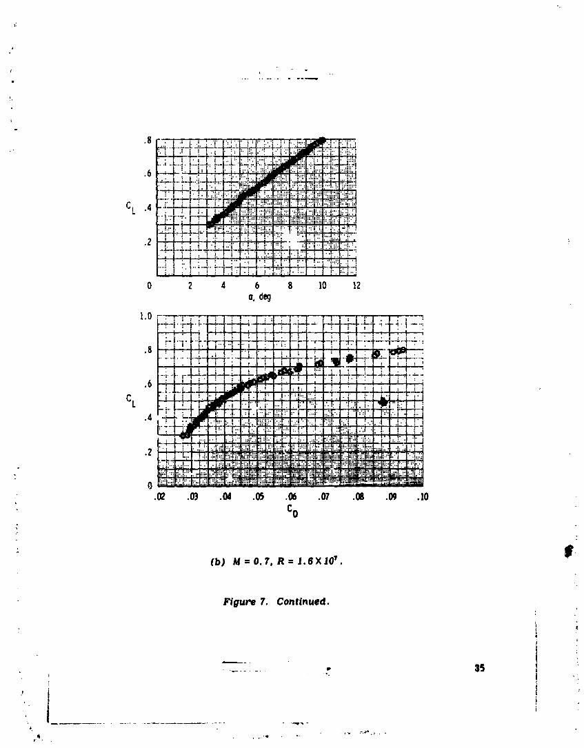
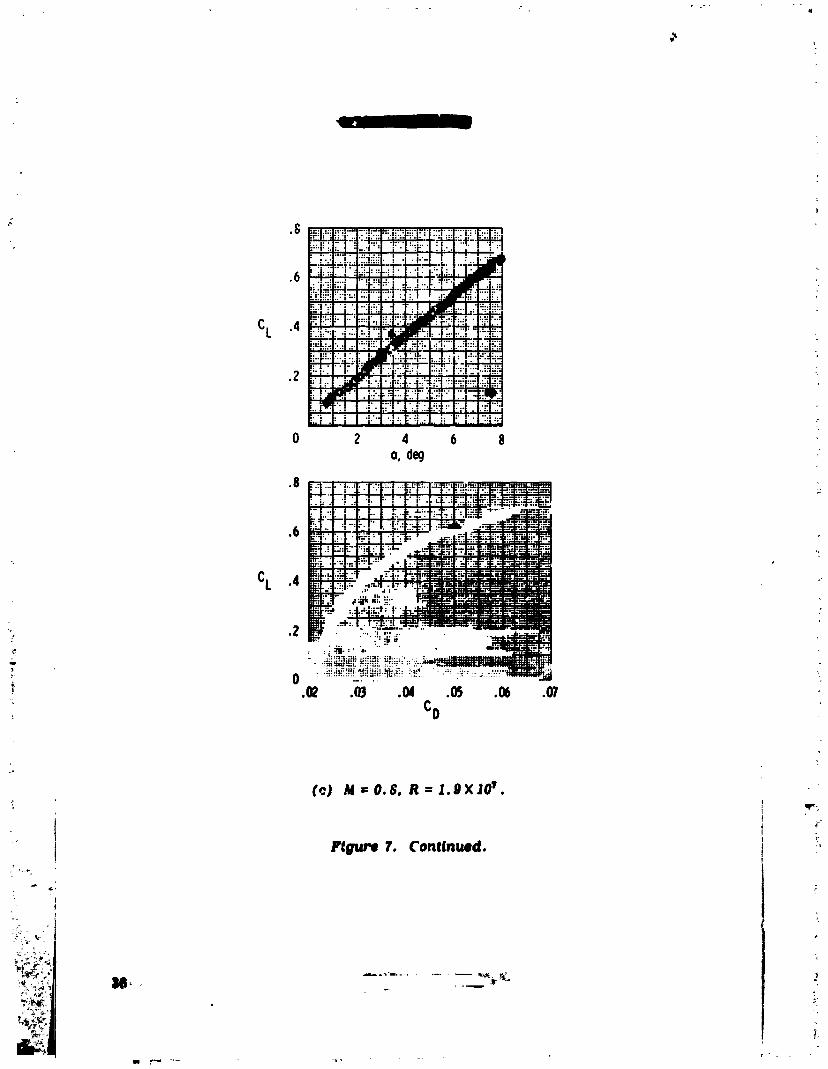
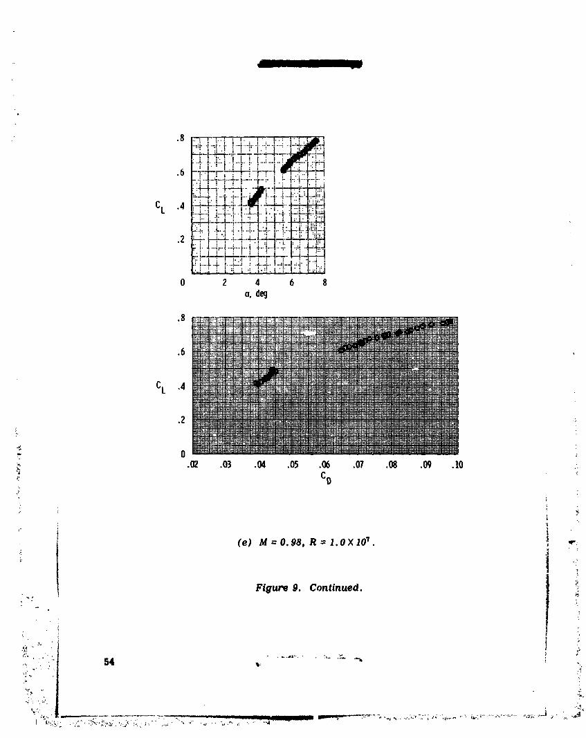
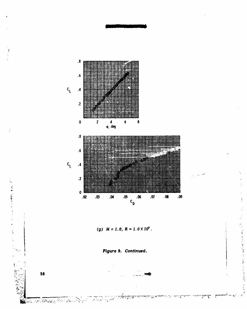
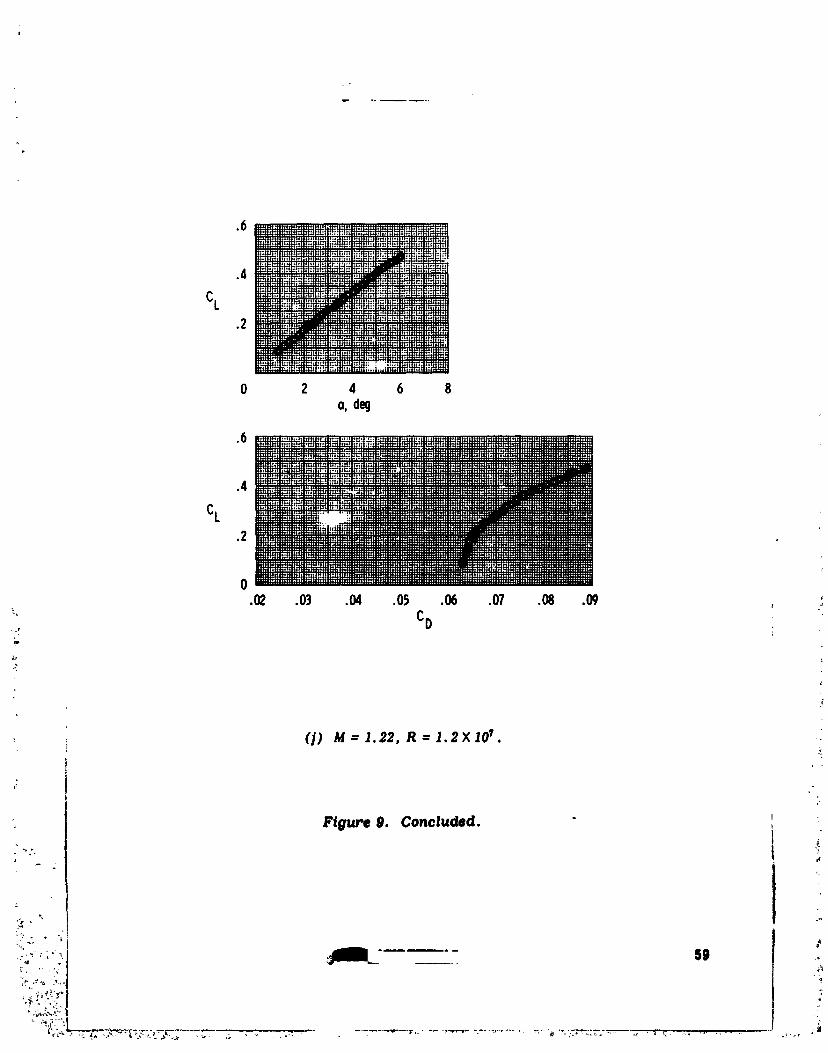
The lift curves and drag polars obtained from flight measurements for the air-plane without area-rule fuselage fairings are presented in figures 7 to 9. Data arepresented for various Maeh numbers and altitudes.
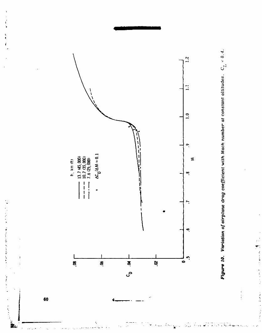
The effect of altitude (including Reynolds number) on the drag results is shownin figure 10. The drag coefficient is presented as a function of Mach number for a
constar.: lift coefficient near the design trim condition (C L - 0.4). The drag-rise :+
Mach number (ACD/Abt = 0.1) varies from 0.95 at the lowest altitude to 0.97 at thehighest altitude. There is some drag creep (a slight gradient in draft before thedrag-rise Mach number) in the data for an altitude of 13.7 kilometers (45,000 feet). +The agreement of the data for altitudes of 7.6 kilometers (25,000 feet) and 10.7 kilo-meters (35,000 feet) is close.
The effect of altitude on the lift of the airplane is presented in figure 11. At thehigher lift coefficients and the intermediate Mach numbers (0.9 and 0.97), thereare some changes in the lift-curve slopes for the various altitudes. These changesare believed to be due to variations in local angle of attack on the outboard portion _
++ of the wing. This change in local angle of attack at the various altitudes is due to°+ the flexibility of the wing (ref. 7).
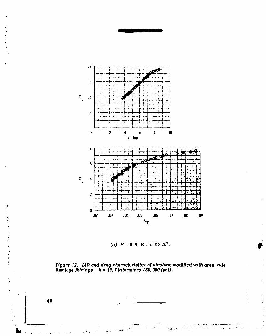
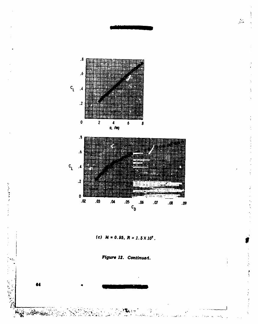
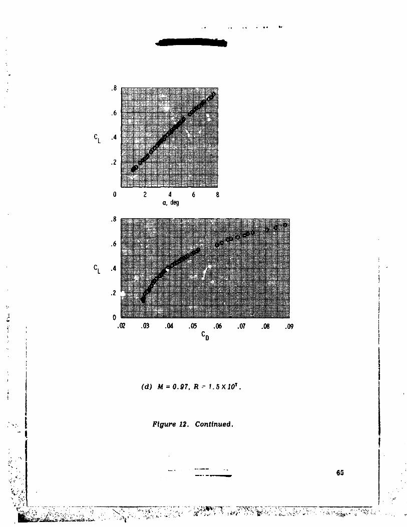
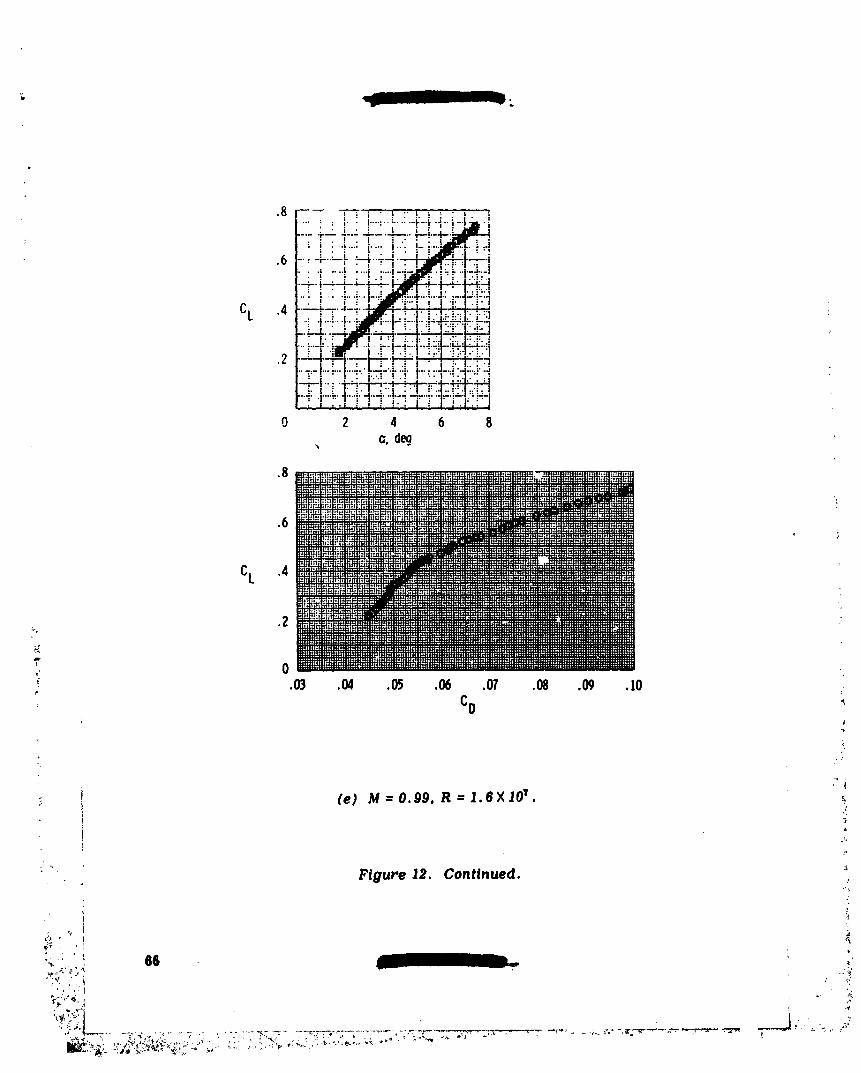
The lift curves and drag polars obtained after the area-rule fuselage fairings, were added to the airplane are presented in figure 12. The data were obtained at an+ altitude of 10.7 kilometers (35,000 feet), and Reynolds number varied from 1.3 X 10⁷ .
to 1.8 × 10⁷ . +
_ Faired flight results with and without the area-rule fuselage fairingsare ,i+ compared in figure 13. The data in figure 13(a) indicate that the fairingshad little
effect on the flight lift curves. In addition, the lift-curve slopes for all Math num- _-+bets are similar.
_+ ,'_
The area-rule fuselage fairings were added to the airplane to reduce its absolute i_• drag at Math numbers between 0.95 and 1.0, increasing the drag-rise Mach number. "
However, the drag polars presented in figure 13(I)) show that the addition of the_:_i area-rule fuselage fairings resulted in slightly higher drag values at most Math
1 numbers. :'+
i '"
%
• ? + .,
%• +
1979024988-015
p .........
Comparison of Flight and Wind-Tunnel Results
{
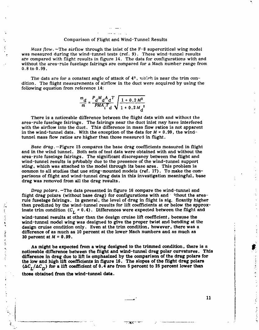
Mass flow.--The airflowthrough the inletofthe F-8 supercriticalwing model. was measured during the wind-tunnel tests(ref.9). These wind-tunnel results
are compared with flightresultsin figure14. The data forconfigurationswith andwithoutthe area-rulefuselagefairingsare compared fora Mach number range from0.8 to 0.99.
The dataare fora constantangle of attackof 4°, v_hiPhisnear the trim con-dition. The flightmeasurements ofairflowin the duct were acquired by using thefollowingequationfrom reference 14:
md_PdMdAdr/I_+02M__'+02Md'
There is a noticeabledifferencebetween the flightdata with and withoutthearea-rulefuselagefairings.The fairingsnear the duct inletmay have interferedwith the airflowintothe duct. This differencein mass flowratiosisnot apparentin the wind-tunnel data. With the exceptionofthe data forM = 0.99, the wind-tunnelmass flow ratiosare higher than thosemeasured in flight.
Base drag.--Figure 15 compares the base drag coefficientsmeasured in flightand in the wind tunnel. Both setsoftestdatawere obtainedwith and withoutthe
area-rulefuselagefairings.The significantdiscrepancy between the flightandwind-tunnel resultsis pI'obablydue tothe presence of the wind-tunnel supportsting,which was attachedtothe model through itsbase area. This problem iscommon to all studies that use sting-mounted models (ref. 17). To make the com-parisons of flight and wind-tunnel drag data in this investigation meaningful, basedrag was removed from all the drag results.
Drag polars.--The data presented in figure 16 compare the wind-tunnel andflight drag polars (without base drag) for configurations with and _thout the area-rule fuselage fairings. In general, the level of drag in flight is sig. ficantly higher
: than predicted by the wind-tunnel results for lift coefficients at or below the approx-
_ imate trim condition (C L = 0.4). Differences were expected between the flight andwind-tunnel results at other than the design cruise lift coefficient, because thewind-tunnel model wing was designed to give the proper twist and bending at the
" design cruise condition only. Even at the trim condition, however, there was a_ difference of as much as 10 percent at the lower Mach numbers and as much as
30 percent at M = 0.99.
As might be expected from a wing designed to the trimmed condition, there is anoticeable difference between the flight and wind-tunnel drag polar curvatures. This
:' difference in drag due to lift is emphasized by the comparison of the drag polars for :the low and high lift coefficients in figure 16. The slopes of the flight drag polars -._•
(_CL/£C D) for a Hft coefficient of 0.4 are from 5 percent to 25 percent lower than _:those obtained from the wind-tunnel data. "_
.?
1979024988-016
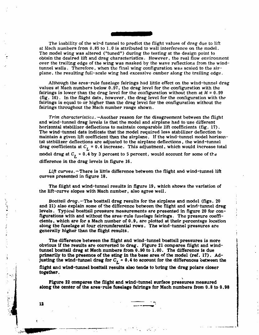
The inability of the wi_d tunnel to predict the flight values of drag due to liftat Mach numbers from 0.85 to 1.0 is attributed to wall interference on the model.
The model wing was altered ("tuned") during the testing at the design point toobtain the desired lift and drag characteristics. However, the real flow environmentover the trailing edge of the wing was masked by the wave reflections from the wind-
" tunnel walls. Therefore, when the final wing configuration was scaled to the air-plane, the resulting full-scale wing had excessive camber along the trailing edge.
Although the area-rule fuselage fairings had little effect on the wind-tunnel dragvalues at Maeh numbers below 0.97, the drag level for the configuration with thefairings is lower than the drag level for the configuration without them at M = 0.99(fig. 16). In the flight data, however, the drag level for the configuration with thefairings is equal to or higher than the drag level for the configuration without thefairings throughout the Math number range shown.
Trim characteristics.--Another reason for the disagreement between the flil_htand wind-tunnel drag levels is that the model and airplane had to use differenthorizontal stabilizer deflections to maintain comparable lift coefficients (fig. 17).The wind-tunnel data indicate that the model required less stabilizer deflection tomaintain a Riven lift coefficient than the airplane. If the wind-tunnel model horizon-tal stabilizer deflections are adjusted to the airplane deflections, the wind-tunnel
drag coefficients at CL = 0.4 increase. This adjustment, which would increase total
model drag at CL = 0.4 by 3 percent to 5 percent, would account for some of t]_edifference in the drag levels in figure 16.
Lift curves.--There is little difference between the flight and wind-tunnel liftcurves presented in figure 18.
The flight and wind-tunnel results in figure 19, which shows the variation ofthe lift-curve slopes with Maeh number, also agree well.
_, Boattail drag.--The boattail drag results for the airplane and model (figs. 20_ and 21) also explain some of _he difference between the flight and wind-tunnel drag* levels. Typictd boattail pressure measurements are presented in figure 20 for con-
figurations with and without the area-rule fuselage fairinffs. The pressure coeffi-cients, which are for a Mach number of 0.9, are plotted at their percentage locationalong the fuselage at four circumferential rows. The wind-tunnel pressures are
: generally higher than the flight results.
The difference between the flight and wind-tunnel boattall pressures is moreobvious if the results are converted to drag. Figure 21 compares flight and wind-tunnel boattail drag at Math numbers from 0.90 to 1.00. The difference is dueprimarily to the presence of the sting in the base area of the model (ref. 17). Ad-
- justing the wind-tunnel drag for CL = 0.4 to account for the differences between theflight and wind-tunnel boattail results also tends to bring the drag polars closertogether.
Figure 22 compares the flight and wind-tunnel surface pressures measuredalong the center of the area-rule fuselage fairings for Maeh numbers from 0.8 to 0.98
I
]979024988-0]7

m,
for a lift coefficient of 0.4. With the exception of the measurements at the 24-percentlocations, the flight and wind-tunnel pressure coefficients on the forward fairingagree well. The flight data for the sloping surface of the rear fairing (beyond
. x/l = 75 percent) are somewhat different from the wind-tunnel data, particularly ata Mach number of O. 98, where the flight pressures are significantly lower than thewind-tunnel pressures. It was not determined whether this difference in pressureswas due to the different horizontal stabilizer positions during the flight and wind-unnel tests, the influence of the support sting, or the effects of wall inteI.,.rence
3uring the wind-tunnel tests.
Total drag. --The variation of the total trimmed drag minus the base drag of theairplane and the model is presented in figure 23 as a function of Math number. The
arrowheads on the curves indicate the drag-rise Math number (ACD/_M = 0.1) ofeach configuration. The drag-rise Mach number measured in flight without area-rule fuselage fairings agreed within 0.01 Mach number of the drag-rise Mach numberpredicted by the wind-tunnel tests.
The wind-tunnel data (ref. 9) indicate that the drag-rise Mach number was 0.01higher for the model with the area-rule fuselage fairings. The flight data, however,show that the area-r.de fuselage fairings did not increase the drag-rise Math number.
Up to a Mach number of 0.95, the drag level of buth airplane configurations wasapproximately 15 percent to 20 percent higher than indicated by the correspondingwind-tunnel results. At these Math number conditions a significant part of thedifference between the flight and wind-tunnel drag was probably due to the effectof the sting on the aft portion of the model's fuselage.
CONCLUDING REMARKS
The lift and draft characteristics of a TF-SA airplane modified with a super- ..critical wine" ,1ere determined in flight and compared with wind-tunnel results. The
.: drag-rise ;,lach number measured in flight _vithout the area-rule fuselage fairings ,: a_,n'eed within 0.01 Mach number of the drag-rise Math number predicted by the
wind-tunnel tests. The addition of the area-rule fuselage fairings to the F-8 super- _ '_,L: critical wing configuration did not increase the drag-rise Mach number of the air-i pLme as had been predicted by the wind-tunnel results
±,
,qigniflcant differences were noted between the flight and wind-tunnel values :for base and boattail drag. In addition, the drag-due-to-Hft characteristics of the -_
_" model were di._,erent from those of the airplane. In general, the level of drag in
4 flight was higher than predicted by the wind-tunnel results for lift coefficients at for belov: ".hedesign trim condition.
, FlightResearch Center_: National Aeronautics and Space Administration
__ _awards, Calif., January 16, 1975 _
i 13 "_: -_
1979024988-018
APPENDIX
" FLIGHT DATA ANALYSIS
: Angle of Attack
The upwash effects from the nose boom and the fuselage (ref. 18), the aero-dynamic forces on the boom, and the effect of pitching velocity and acceleration onthe angle-of-attack vanes were computed and corrections were applied to the data.A static calibration of the nose-boom and the fuselage bending with normal andpitching acceleration was obtained by loading the nose boom. The results of thiscalibration, which are presented in figure 24 (a), were applied to the flight results.
An in-flight calibration of angle of attack was obtained by measuring the longi-tudinal acceleration of the airplane in steady-state trimmed flight (where the changesin velocity, V, and altitude, /_, are zero). If the steady-state trimmed flight con-ditions are maint.xined, the true angle of attack is equal to the arc sine of the meas-ured longitudina_ acceleration. Although zero values of _/and/_ were difficult tomaintain with the F-8 supercriticai wing configuration, the deviations from the_trimmed condition were small and could be corrected to obtain an angle-of-attackcalibration. Figure 24 (b) presents the correction to tt, e angle of attack with thevariation in Mach number as obtained by the in-flight calibration. This correctionwas also assumed to be valid for the nonsteady-state flight results (angles of attackhigher or lower than trim) since the angle-of-attack range of this study was small.
_ Thrust Determination
- The thrust of the F-8 supercritical wing airplane was determined in flight bythe difference between the inlet momentum and the exit momentum of the airflow
:_ through the jet engine. A complete discussion and derivation of the thrust equationsis given in reference 14. The inlet momentum (ram drag) can be calculated by thefollowing equation:
[ 1 + O.2M d"
FR = YPdAdMMd _J (I)1 + 0.2M 1
i The static pressure in the duct, Pd' was measured at the engine compressor face
J (see INSTRUMEI_.TTATION). The cross-sectional area of the duct, A d, was measured!_ at the engine compressor face, where the static-pressure and total-pressure meas- :_
urements were obtained. The free stream Math number, M, and the ratio of specific ._• " heats, y, were determined from airspeed probe data. The Mach number in the duct
1 M d, was calculated from the following equation: . _
m,_ "
1979024988-019
APPENDIX- Continued
The gross engine thrustor exitmomentum, FG, was determined from the meas-
urement of the freestream staticpressure, P; the area of the exitnozzle.Ae; the
thrustcoefficientof the engine mounted in the airplane(calibratedon a ground
thruststand), Cf; the ratioof specificheats,y; and the measured totalpressure
ofthe exhaust, Pt " Gross thrustwas determined from the followingequation:e
F G = PAeCf2y-__ 1 - (3)
Pt
e ,up to 1.851 with the after-This equationisvalidforexitpressure ratios,--f-
burner offor 1.802 with the afterburneron. Below these values, the exitpressureratiois considered tobe subcriticaland the flow is subsonic. When the exitpres-sures are criticaland the pressure ratiosexceed the values above, the equationbecome s:
FG=ACf[IV-} (,+1,p,- (4,Severalthruststand calibrationswere made ofthe engine mounted in the F-8
supercriticalwing airplaneto determine itsthrustcoefficientatground level. Thethrust levels were obtained for various exit pressure ratios and are extrapolated toflight altitude conditions in figure 25. Altitude chamber tests on an early version ofthe J57 engine indicated that a variation in thrust coefficient of less than 2 percentoccurs at altitudes between 4750 meters (15,000 feet) and 15,250 meters (50,000 feet).
_ Therefore, the ground thrust stand results were extrapolated to the flight exit pres-
sure ratios on the basis of previous experience with this engine (ref. 15 and unpub--, fisheddata).
The net thrust of the engine is the difference between the gross thrust calculated;.. with equation (3) or (4) and the ram drag calculated with equation (1). Thus, net
thrust can be calculated as follows: _O1_F
FN-%- FR (5)/
_ Drag Determination _
Once an airplane's net thrust has been determined, its lift and drag characteris- .'_
: tics can be calculated by using measurements of longitudinal and normal acceleration.
L ,
_" ]'t I
J
1979024988-020
"_ APPENDIX - Concluded
- The following equations were used to compute the normal and axial forces from thesemeasurements:
Wan
cN--_ (6)
FN - Wax
Cx - qs (7)
The i0rce coefficients are transposed into the body axis coordinates by trans-forming with the airplane angle of attack; thus, equations (6) and (7) become"
CL=C Ncosa-C Xsina (8)
CD = CN sin a + CX cos a (9)
L = CLqS (10)
D = CDqS (11)
• i L CL-_ _ /_ = _ (12)
_.:. =i
* ii.%
ii "
_,il. I 16 ....................."_
1979024988-021
_p
REFERENCES
1. Whitcomb, Richard T.; and Clark, Larry R.: An Airfoil Shape for Efficient" Flight at Supercritical Math Numbers. NASA TM X-f109, 1965.
• 2. Whitcomb, Richard T.; and Blackwell, James A., Jr.: Status of Research on aSupercritical Wing. Conference on Aircraft Aerodynamics, NASA SP-124,1966, pp. 367-381.
3. Harris, Charles D.: Wind-Tunnel Investigation of Effects of Trailing-EdgeGeometry on a NASA Supercritical Airfoil Section. NASA TM X-2336, 1971.
4. Harris, Charles D.; and Blackwell, James A., Jr. Wind-Tunnel Investigationof Effects of Rear Upper Surface Modification on an NASA Supercritical Airfoil.NASA TM X-2454, 1972.
5. Harris, Charles D.: Wind-Tunnel Measurements of Aerodynamic Load Distribu-tion on an NASA Supercritical-Wing Research Airplane Configuration. NASAt
TM X-2469, 1972.
6. Bartlett, Dennis W.; and Re, Richard J.: Wind-Tunnel Investigation of BasicAerodynamic Characteristics of a Supercritical-Wing Research Airplane Con-figuration. NASA TM X-2470, 1972.
7. Supercritical Wing Technology - A Progress Report on FligIR ,.'.valuations.NASA SP-301, 1972.
8. Mechtly, E. A.: The International System of Units - Physical Constants andConversion Factors. Second Revision. NASA SP-7012, 1973.
9. Bartlett, Dennis W.; and Harris, Charles D.: Aerodynamic Characteristics of anNASA Supercriticsl-Wing Research Airplane Model With and Without FuselageArea-Rule Additions at Mach 0.25 and 1.00. NASA TM X-2633, 1972.
~,
_ 1O. Harris, Charles D.; and Bartlett, Dennis W.: Tabulated Pressure Measurementson an NASA Supercritical-Wing Research Airplane Model With and Without Fuse-
lage Area-Rule Additions at Mach 0.25 to 1.00. NASA TM X-2634, 1972.
- 11. Harris, Charles D.; and Bartlett, Dennis W.: Wind-Tunnal Investigation of_.. Effects of Underwing Leading-Edge Vortex Generators on a Supercritical-
Wing Research Airplane Configuration. NASA TM X-2471, 1972.
12. Richardson, Norman R. _ and Pearson, Albin O.: Wind-Tunnel Calibrations of fa Combined Pitot-Static Tube, Vane-Type Flow-Direction Transmitter, andStagnation-Temperature Element at Mach Numbers from 0.60 to 2.87. NASATN D-122, 1959. I
y
:i 13. Ritchie, Virgil S.: Several Methods for Aerodynamic Reduction of Static-
Pressure Sensing Errors for Aircraft at Subsonic, Near-Sonic, and Low Super-sonic Speeds. NASA TR R-IS, 1959.
" - 17 ;-#
I
t •
1979024988-022

. _,...
14. Bee!er, De E.; Bellman, Donald R.; and Saltzman, Edwin J.: Flight Techniquesfor Determining Airplane Drag at High Mach Numbers. NACA TN 3821, 1956.
15. Saltzman, Edwin J.; Bellman, Donald R. ; and Musialowski, Norman T.: Flight-Determined Transonic Lift and Drag Characteristics of the YF-102 AirplaneWith Two Wing Configurations. NACA _i_! _56E08, 1956.
16. Horton, Elmer A.; and Tetervin, Neal: Measured Surface Defects on TypicalTransonic Airplanes and Analysis of Their Drag Contribution. NASATN D-1024, 1962.
17. Lee, George; and Summers, James L.: Effects of Sting-Support Interference onthe Drag of an Ogive-Cylinder Body With and Without a Boattail at 0.6 to 1.4Mach Number. NACA RM A57109, 1957.
18. Yaggy, Paul F.: A Method for Predicting the Upwash Angles Induced at thePropellcr Plane of a Combination of Bodies With an Unswept Wing. NACATN z528, 1951.
18
* i.... . ............... _ _ _--r _
1979024988-023

m=


/
"i _ 21 4
: ,_ -_ o...... , ,, _
1979024988-026
P
(a} Wina-bodv tunr.ture. E-25080
FI_u'e 3. Fo_r'/ngs and protuberances.
1979024988-027
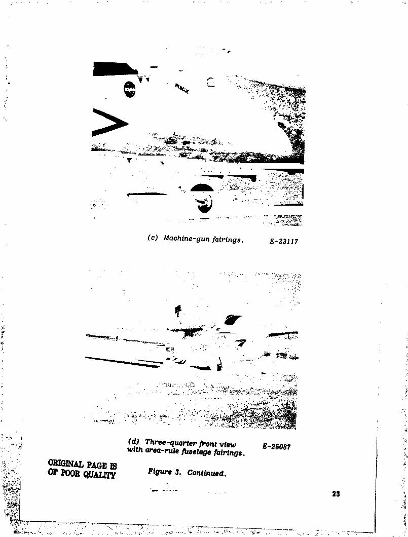
(c) Machine-gun _airings. E-23117
l
. jill - _" , "
" ' " ' " • "','._:__-_._'_."_',_..._R,_
• ,_ ' " , ,;. " ' " , " • _ '>.". ' ,_"'_II_ ",,,_'i_'_"_ ' i_I#_"-.i_: .'li_
; _::, (d) Th_e-qua_er _ont view K-2,_087.,,,_ with area-rule _selage rairings.
!_.::_ ORIGINALPAGEI_ Figure 3. Continued.:_"'.:+_ Or _)ORQUALITY-:-,'--' 25
iI,@I
""" " " " "" .... 1979024988

4o
• J •
:: (e) Bottom view with area-rule fuselage fairings. E-24893
" Figure 3. Continued.
?
,.._,_INALPAU IIoF_oR qUN.11_
24 ....-- .......
1979024988-029

-$,
F Verticaltail
• _ / fuselage
O.203 / IO.75)
U.U'g
(0.29) Pulsecodemodulationsystemantenna
Camerafairingplate (onbottomcenterline)
F.S. F.S.F.S. 19.53 15.76
Fuselagestation(F. S.) 9.42 Fuselage (50.96) (51.71}
9.17 (30._) (30.92) centerline I I0.06 I o.2_ I . o.23__
r- ,o.,, °Frontview Sideview __. (_i__ _-'_'_
o.L':= Anticollisionlight .-n=_- (leftofbottomcenterline} •_. 12.17)": Drainvalve
; if) Protuberances on airplane and wlnd-tunnel model. Dlmenslonsare in meters (feet).
Figure 3. C ontinued.
....... :i
1979024988-030

0.21 ,._"" _0.o9) /- Wingcrosssection
/_ /
_ I 10.48)
- vo_;_g;;e_;,;_......................0.15(0.50J
Vortexgeneratorcrosssection /(lO-percent-thickClarkYaiHoill
£
_: (g) Vortez generatoP on bottom leading edge of wing. Dimensionsare in meters (feet),
Figure 3. Continued, f _
_ 2ti
t
1979024988-031


wU
/
(a) Base area and variable ejector E-25076nozzle with tail pipe probe.
- _ _. :_ /
(b) Compressor face rake and E-21770static-pressure orifice.
• Figure 5. Thrust instrumentation used to determine !inlet and exit momentum of airflow through eng/ne.
............... 29_. ! _,_."_J-
...... ,,,_',,.l-_kPAGE IS,. O? POOR QUALITY '
£ I
] 979024988-0:34
.a
] 979024988-035

10.2
Coolingair outlet-_"_ (4"O}--J"_
i Pitot-pressuretube
2 l- _" " Coolingair tube
I
; (d) Exit nozzlepitotprobe. Dimensions are in centimeters(inches).
Figure 5. Concluded. ! .o
?
1QTCI/3OAoQo r_oe

.... m
4
l
,_,- S2 -_,_ ;_ _ ;
?i/_,Jill I • il i iii im
1979024988-037

._ -.-._-'" .,
-" ': m_,
. T • V T _-
A ' A
i
' 1, (c) Orifices on all area-rule E-25815
fuselage fairlngs. !
Figure 8. Concluded.
: .... 33
k"
'_......................... " " """ 9024988-03_ ........ 97

•..'._...I..._- ' ...'.-L..:.... "-._-;...:.: " ":" ".._-" "';'::" ._-;- _.i _'". • , • , ,I...._.,....,..,,..__i....,.,.:._:."i_:... .........,.,• . T ....... | ........... . I .....
""." : i : l" !. I..'!.-".I.., i ::..iill_..'; .'.-..I..?:I:!':I:..'i':;T.'-T:!_F':;';:!_i"I:i-::I....:.-r._l.--t._?r___>'-!_:$_?_...:_
CI .4 --_ ; , i . , : ' I .:.:.. ;..' .... ;..... '...: : .::;:-i ! : I :. J :' ..:_:"!!.':v '."i:':.:!..':,::_:|':::..'::.""F::i..:.::'" ":.i.:]" ....... .-. r--.----. ...::._.: ........ .-.:_...-,... j.......-.-.I,,, ,, :, ..... _ , .................. :................ . •.... !
J i :"| ' ' ? _"!:F:|" "_'.."':.! "::i:'::!""| """'"r. .i: "''t.:"' zj. !.. | _ .-'-' !
,._.t:..+._.-.::.._.>..,_:_,,._:-...,_-..::: t.._,.._..-.....-...
! I :. '.' ; i : I :";". !': I'. L"! :..r .'..;-:..:.n. : .![.-._i ..!...._.._--t_-_-.._,.-.._---l.-.-...-.-._;-.--l--.-iF._._I l..l ; i : ; : i "i "1"i "J : .,:..:.:; .... I :v : .r"._"_'
0 2 4 6 8 l0 12o, de9
" " _-- ....• " : • : ! "l " l ' I " "' ! ' ] ; _- r | ! ; : | , | I '-- I • i ; ; • : ' I ' F '
i i--!"-'- ,_+ -k'.,'.: _.:-."_-._r-k•r'--F:" �œt .....+--;4"_"_-!' :.$ _; i ;.1 " _''i ,_.i ,'. : '-" ! " : . " "" ; " "• .. _ , . : I . , ,. / : [ : / • _ • I _ . ._1 .q;_M_.. •
;_.... -_[. i. ,_it..-'.- -"_-f, ; i.""-i''_" "-'-'l'-i" ;,,_ril_ ._1.._ _lt. _... r ; _ ::. .--. --i-. . -- -;'" _-'":'"i" ......._ " ' : ' v _ ' : • _ '-" ; J ! J " I _ ', . '- I ! I "..• : ._ ..,,.dl_l_. I ,"'l : n _n,, , : •r";"T" -"r"_'.'.'T"T--i-'.'_- :, ,mnr :. I; '. I ' I..'-"r"_'.-F','":-'1"_"" I : .1".- •,. I; I" l. '. , . _ ,............ I I..
1: r " l ' : i:'' "" : l J !' " I i .I : I. • .L_. : : ". _ ; I .: .: ..... ." : : I I I .
CL
,.,_ -..,i=I-_' '._.;..,,e_".r ,...._,. ......,,...,,, :. ' "!"!.:i"l".i':":.":.I:'_"! "".:"::.:i:.'"i _i-_:'.f" ]" i•-.".,-.-Fi] _+_,.+,.,,_..._.._.,...__.._.._.i._v_i..: i i
14
. i ._' : "l:::':':" "'" .r .I..;'... v ' "::1. . .i'" ....; .....' ".,-..-._.., .,:,:.,.;..,.,.....!. !..::....::i!..!....:i"" i!."-_":".'-_.'..,• ,"W_'l'. _.' ...... i.'"_.: .I ........ I .' ,.'.|:': ..l:: : ..|. I • I- .I.
i' =
•2 '..! ; ;:[..[:''"'""r'':'F:'i;i:.i.?:'.i!,....:..,.,;..,:.,......_:.:::.[..:;.:........;.,I.i::. :;:, :' :::...2" ':.:; "-:'|: .: •. .... ' •.':i.:::!_;::!":,,i:.'l'_i"!:::|_f:':_'_i"':_:::":'_1,'_!,_::::..:I-::_;_._::_::::,,.._.! I".!::.
0 '';:i'':_....." " "':•0_ .03 .04 .05 .06 .07 .0_ ._ .10
Co
: If(b) M=O. 7, R=J.6×JO _.
Figure 7. Continued.
........... - a_
' i_ _,q _
1979024988-040
...;..
(¢) _ : 0._, R : 1.gXlO _.
-_ Jl_"dg'u_7. Continued. !:,
,._%
_. ;/ .._.,-............. ,,• _ %,_ _ , .,, , ,,._
]979024988-04]

.8
.6
CL .4
.2
CL .4
• %l'n . ,',
" "- _ 3?
1979024988-042

F-::_.i.-i.-_:.._..:.;_._:.,I..._....i.;..-i.-.ii-.-_...i_-.--i I:..,,' i...:..i_...._..._.:.:..:...- • ..._..._
' t.:-ti:¢:i:__?! ' '_---*";,_"._ 'ct -._.-i-_.__..,."::-._ CL I:_;;;!;;;_
i [;-i}-._!..-iil '":+__ii!.-i:i_--;":::"' ....."',=i'%": •'_!_i'."=."ii""...._u....{_!:t'.i'i'::4
!..:!_.liT i iPr:T]0 2 4 6 0 2 4 6
e, d_ o, deg
i;..i,-,,.;=..,.6 !i'_'__.-.:i:.L.....i,_.:'_ .6r_:;.!:.::...........i:.:4".[.__":IL""':':..,...q...-:...,' _ .... .d. ":[llll_{|':!'!._:'l!_:.i:_!_l':!1'+!I •4
_-.-ii_:_!::}i;ji!i!!l!!i;N_ _ : '-":!::_:-_ F.'..'__:!i:-i....]i..:i'.i.':'i:.:.:.;i__il_i;_ __
.02 .0_ .04 .05 .02 .03 .04 .05
CD CD,.<
•_ (e) M=0.95, R=2.2XlO _. (1') M=0.96, R =2.2X10⁷.}
Figure 7. Continued,f
"t
$$
i
1979024988-04:3

b
=
,6 , . '" T :.i....:"i
b!'CL :,. . , .... I.. •
I' i": " l :. " .i'. "." •.2;..;--_- • •
0 2 4 6a, d_
.6 --i::"+ i " i:....""::! '1:i_::::'_b-'!-,' " i'i-,...""""'"t::.:_,i.-_t.."_',_lI _+.__
• L ! "" " "'L"'-".:.:l='::
CL "-, i '.. .... i...... i .....I.,_I:-i-_,+ _I....H,,,,,..._...,.,,I...._.... , ,. : • ,l:i i • : ::.:.':..: ,: :F::..:::}" :::
+- ,_ .03 .04 .05 .06
?, CD
(g) M = 0.98, R = 2.3XI0 T.
Figure 7. Concluded.
+
i 39
'_ :t ......_,i;X
5!
1979024988-044

.6
CL
.4
.2
O.02 .03 .04 .05 ,06 .07 .08 .09 .10
CD
g; (
(a) M = O. 6, R = O.95 X10 v.
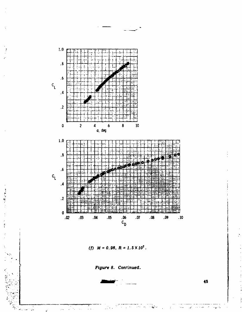
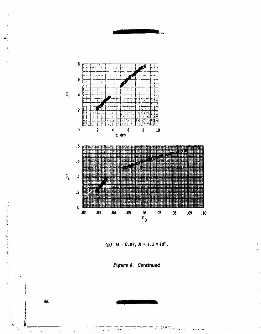
Figure 8. Airplane lift and dr_g characteristics at an altitude of '_, 10. ? kilometers (35,000 feet).
40 _
!_
1979024988-045

L
- .8 !'+ _5_'::tF_].._..-2-..__!!i!__:_?.G.b:i<,:._:':,.....
,+;_:::;-_£;::_ ii-_::._:-."iii:+:i;i!l_;;_i;ili_i':'"_:_ii_ii_[i.iY:
0 2 4 6 8 10o. deg
I.O ..........::" .:+,_'_: z'+. +,++};+_ .+:'%+: m • +. _ _ , ++.+,+_,+++++.
_,**mmmmlmm+ :__$M_ ._."-i._a_ ___"'+"+"++'+_-.-_
.+ _C!,._ mmmmmmmmmmm++_+ I , I ............................
• 4 ::::,::::+::==:::::::+::::::::::_:::+:::::SiiifiSi:ii":_'Y'_i_i:::::=;:=:::::::::::::::_i--ii_-_:::::::::::'-'_:_:'';;:::::
..... __ It......................
.2 __ _ ..................:.........++--+----+-++++:++:+.+++................... ======================================
.......................-.....................+;L-.--_++::+;+.........:+:++:_+.........+. 0+ .02 .03 .04 .05 .06 .07 .08 .09 .lO
,+ C0
+.++
++ (b) M-O.?, R=I,IXIO _.
"'+ Fig" ure 8. Continued. _+ + +
, <
"+,. :. 41 +f,_ + , ++,
!++ ,++P
-++ . +._ , + +.+ ,-. - +--, . • ., + -, +- , . + ++ .k _
+r " +l " "'+ • _ + + + m+ .. , e, , _ *++'X-p_ +++ ,_ • ' "+ 'i _2.+ +++: ,++ ++ +. + , _,+ .+;.++ +-+ + , + :++, -."
%
"1979024988-046

.8
.6
CL
.4
.2
.02 .03 .04 .OP .06 .07 .08 .09 .lO
/
(CJ M=O.8, R=1.3X10 7.
Figure 8. Continued.
42
_,i _ ,. i ...... n p • •
1979024988-047

- .8_,.:.: ... ::i..... _:..: ::..:. :..::.:...:j::_ :... : .:::....':'.':,..+' _.1i:: :..::: •
:. , .............. :'j. •_::.._. :i. "'! I .. I .'" :.1...... • "" :" .. I .: "? .: • i
.6 :_._.__ _-mq¢...l:i":l:++;i!i;.r.iEi._. i...i r._ .+.w..._.._ ;.:.i:.._
P:!-!_i-l: i..i "-_-.... :..:_-::.". i:=_l..=..._:_i_._i•_ .4--i-.: '" .i--" . ;L :,_.+.-=.:_ _:
.,."_:'!-i I _=r,"'-_- - -;r'__:-"::---"'i .....f'" '..-"'t""i ":!":.:_.'_-"": !" "!".-I-_k:!i _."_i
• _ .: ,.i. " i ' i, ' .I : • I • I r ",.':r:::i ....."' " I• ! "" ! I ! I .:. : ' :" :':' .:..i. "1. "i.: .... I.::
-.+.-.t.....+-!.!.-_-_;-i-•::-i-.:!,:.4-:.-1.-:i...-:.+_=_.'.'-._.'_: .:._j..'. , : /.. ...:' I _" i":':l .I';:'"":':::
;--._-....i..."-_ .....!_I...-...:I,_;_-"_i_:!; i :17 i _ i. ! i I". i " !'.1 '1 ::1'::!'.':,:!i'ki::":liP:'
0 2 4 6 8 10o, de9
.8
.6
CL .4
,2
, 0. .OZ .03 .04 .0_ .06 .07 .08
" CD+
(d) M=O. 9, R=I.4XIO _.
= Figur'e 8. Continued. ' _
,I
:- - _ 43
1979024988-048

.8
i!!ii ii!!i!ICL .4 .. •
: I ,, ,
.2 ......... ;. • ;-- -_.--.--..---;.-_..... i - -....---+.......• i : " : : i i ...... '.": :
•":"......i.....:_......:,'......" .........._............._.......- " _ ' i " ! ' _" _ ' !" ! i i ' "i i i • • i L i _
0 Z 4 6 8 ]0a, deg
.8 I " " ' : ..... i ..... = "i .... ._,' 'i ! " ! " _ " ! "" I _ ! "i ..... i.... ! " ] ,_-.iD.""_'']'_'! ":""; = : : : : : . = ; • • _v-.. • = . .. . : !
I • ,: • i... : .. i • _I_W_, • " ..... i .... i..:.." ; ._ . ..,'. :...i : .i...: ..I .... :I _ " i : J • dlt,qT"" J I i : _ " " _ ! " '". " : : :
I ...... :......... + ......... -..... '.-_-.-"[....... '+----';-'--'--';.----t" ";.."_...... �œ�4�.4-......i `�i
: : .....i ..... : ." ."'! ": "':. i......t.... i ; ! ! '1"'.' i":'"i" i• I , I : " : : : : i ' : " | , I ," I " " i
CL .4 _--;---r-._-]-...,illF---.:......; ..---r.--i "_--i ....._-_---!......r-_-F--T ..'---T..'.'.... !.... _411_'!-.!...i ....i .I......l.... t'" ;'" _':" ;. ......".... _": !'_"!......-_'"'_= -:i .--....... !...... " ...'. "---J- .... ! ...... "--_..... _-.-J--.---4----...-.--_L_;---;I" ; . • : . : = • • . I, ,.,.'-..-:-_-- .......... , . , . =i'":'t ._T'-'; : i-':"-" : "'._'"'""r ;" :'_ • ; .... i .....:" r= i.-:.........
.2 _..:--'..',:i i--.!.--_--.-q_-i .......':---".---.--i-----........_.......'-..----_._.--I " •_--......_..-.:I •; _-_-.I.......l.......i..;..I ......!..............i i. i...;....,.....i.......i-: t/ ; : . I • I ' I • :. : .l" ":: I : ; " : : I : ,r : l • • I•I:--'--_-.".---_ .-L."...'---:..':T--t---:.--ff-ffd-....... "-.-,--;'--'-_..-';-.....'r-'--'-I! I :•.I::"i....i......-..-.--.-l.--..:;.....:,:: '.:.---_...........:;.............= • ' _...'....'....4....i....!....:....="'l.."=":oJ.,.l ,.,.',,,,..._.._.I...,., ,.,
.02 .03 .04 .05 .06 .01 .08 .09 . lO
: CD
_- (e) M=0.95, R= 1.5X_07.
F_gure 8. Continued.
44 ' " - !_
1979024988-049
- 1.0 _.l::;..il.i i .....I._F::_ i' "' ":" .:".'T'"i":'""!"'" ":'":"I"":'""'........._.._.--+...i---.l..'...-_--_...-J_;_--H x���_....f._-_'.--..-.:. • : '
.__ _:;-__;•:; i ! '" ! ," ""' _ i :q-__''.L-._."AI_.....'..i.-:J,:-!-_..--. -_--_.- " ..--.L- : _.-..4.. "...-_.... "'":._-L_:. , : , .T. _ . I , "b__"-:_.-..I......i..,.--" ...•F-. , ...,....i_... i .i l!!!.i'--,
: ". : I • I : • " .J..: : . . :.. :'". ".'"
_'""--+-'..'--i .... I • i .._ •i-I "'_":'r'"_•'. _'"'! .... i "_':'i"'":"; :'.....!:-:+i. "l
• • _ ,'F-."'I _ J _ ,.i .:_ .-'
.4_i!i4 '*_]-_
0 2 4 6 8 10o, de9
1.0
-,' 4"' ''.....{.........._4_:.J: ] _ • : ! _ , ".,! : ! :":'_::-.:i...:...:_ -.":1-:"1 ;......".....', [ ...._....!:"J-rt:T:-Ii::r]:: '-._:;.!-:_-;-' :_ _ , i .=_ ' _ .. i. _._ _ I.._ .I _ _ :...:.L:i I..+:-i.._..--+.... r.-i" -_. • |.-:- ..... 4 "I .,i I.--4- t-'4-:.l-- -_'F-, :,-':.I.: 4. •! -.:--_,,--.'_-,_::::..,"_ :'-_'.:--..." :/ _ I " i I" ! i:i I. {" 'l..':.:l""i:'l': ;_"I i !.,. _'.: ".!'F;!! ',...i,lil
.8 [:.: i:..ii ill i!i ..i I..i:_:F':!.'.;l."':l:'-.':..'_'"i.-,:ii'._ti._._."-_--r ..... ,'_"-- " 1 _'"_ -- :..... 'I,..... I_" -- l"-i'_ .",",-" ';';"--_'" ' _ ,_,,":';r'
:.. : 71 : I ; ! , : I..;.:!-F...I.l..i_._.l..l_...I ..... i.
_"" '" ! __t_-:-_-:'"''"""""":_:i.._t-4..:-#-.i.-_....;-..I--.k.._-. . .,: ---_.6 "'"- : "": .'_ i i:: ._i_i -:_!i:." .'ll:.;;::_.i:::':..',".,.'l.:,'::i ..
.... "_,1 , "1" , ':" • ..-:-i.7.:'.I'.F::.i.. ,:_:r.'_l:,_-_...-...-:!.-.._.--t.,.-.,:::":::CL :l..._:',"".:i:";_i:;, :_':iii_.:i:;.i:i:;_._-._,--:_.-.,i,.-.-._: ...-i-,..:i....,.....,:..:--i.::::.i:-._ii17,7;:....... _ ....... i:iii:i: i [
.4 "'.';"" .'; • ........ !
_! "iii _ .""""':" i::_-- _ -_:i _:._i.'::_:'t:"_;=..i_:i'.t:';:.:i:'i:!:_":_-.':iiiii!i!i'ii;I,"_,":"., ;.!', •:.i_:..:.._-:'-,._:_.-_:,:_._:i_:..._-:l':_'....":,:.....7_7iTi:77.'-'..i-rl::!_i_i_-.:r.:'..: ,...."-, i!iii!........_ "i ' " '''_"'':':"_'_............i_7'_ _-_7!i_..-..-..''":'":'.......-.,..--:",'"':.._Pi_":"":_="--'_'":"<.:,:,'i:'"'_!.!:"'.":':;!'"ii. _'_" ' ...... :
•_ :_i_;.iii_-___i_'_':_::'<_:_iii__" :::'!::'::'::::"_:_ _:_::+ .... ':..,. :. ,,:., .._.-:--::: 7.]:"' ':i":T'"'"I:: ,'': £7".':'.'!' !::'i:!:
-:'":"_......._i- _- _:--_i '"'"_':''......._ .o_ .= .o_ .= .o_ .= .w .lo
'_. CD
: I (f) _ =0.98, R=I.$×IO _.
,._. Flyure 8. Continued.
i_ _ '
] 979024988-050
.2
_. .02 .03 .04 .05 .06 .07 .08 .09 .10
:_ (g) M=O. 97. R=1.SX10 _.
Fig-re 8. Conllnued.

CL .4
•: (h) M=0.98, R=1.6XlO 7.
r
Figure 8. Continued. ,;:
I
.......... 471
1979024988-052

CL .4 ?
B
+:
,8
•.. : ..i .... i.-:................................. i...__,,;,...__..i_._ ....
' "" ! ! ' I" .• , ;.... ;.... ,. , ,......... ,.+,.....,...........-.....,......:-..i..-_-
cL,i-+...................ii" : : _ ! ! , "",t--...-".--....- ......".----,.-.-Jr..--l--_t.-.:/: J +: i i :i ;_ : i ....
0 2 4 6 8o, decj
l"+"_"'"i ....."-""""! ......F" !".-"i i:"..:""..".... ;-" !"'.". .....!-'.! ....i/_:!: i +. i _i.-,*-.-+-_,._-r_-_-_...: i ! ..--:F.--:.--..L...;...I :, " ...... '.-.:-..: • "..... i ...... i...... Ø���Är.-_---'.-..-':• i..: ._ ...... F'.- 'I._...L: _ ! ! : i ._ _ i • ...L..I_L.L_! + +. i : i__..._
.6 i ; • " • I • " " : " ' " J I . , ,_,,_e_+ :.... I " " + ' ' I " l 'L.." .,..,..-;.. t........... _..._.... L..... :........ ;....... ;, : ..... 4 ......... ..._|l-._. • : + .......
i-_..-:-_.--t_¢-- ;.+i i ;.j _'__._o'i-.."I.i..t_t.! ,.L_ .¢.."..ip.....[.-..i..: ..+..--1.-.. +.....1. : .Idpl_...Tt.L'-...:-..t-"-J........i: i • / : / ; ; : i : " ; : : :,lllzr, ! ! l" : i : / : : : i
CL ,4 •'' , :.:--+-_ , t : t--'l_.._------+.---_l-;+-.._ ...........t.:...-_.---i _..I..;..t.....+ i_..i..4 _ 4 -_...l.+I..-:...i-.:-+..i.+.....i: / : i • I • I : . t • : _ _ . i ! I ; ' • _ I : " ii t t t ..'--i + , : t ;',+'. I +,=-! : I _ ! . ! . !'. i : I
-: t .......!! "-:--+-"i _I-."-L,I_ 'i .......F i. i--.i--i--.-i :I--.... I, i12 ; ' " "-- • l • . I_" | " : " I " " ' " II I dp ; " -- I -- + I _ I I i 1_
• I : : I : I ! : , • . : r " : : I" : l "" :....-,:._ ......_....-+-..+-.+..,....-._...-_.'..j-....!--l.....-,-•-,.;..---,...,....I..:..._• i ; : " ; / l " I _ I • I ;, • ; I ' _ / • ', s : •
+i : L+++++, +, :, + ! : i _ + .-T.__....i i......,"r i _ " -'--'i-t.... _ " :'"I:-'-I-"r'" .......:+ i"'" .'-" '", "!--io ,, ,,,,I..,_T,I:,.,:.,.I.,..T.,I..,,.,.02 .03 .04 .05 .06 .07 .08 .09 .lO
CD
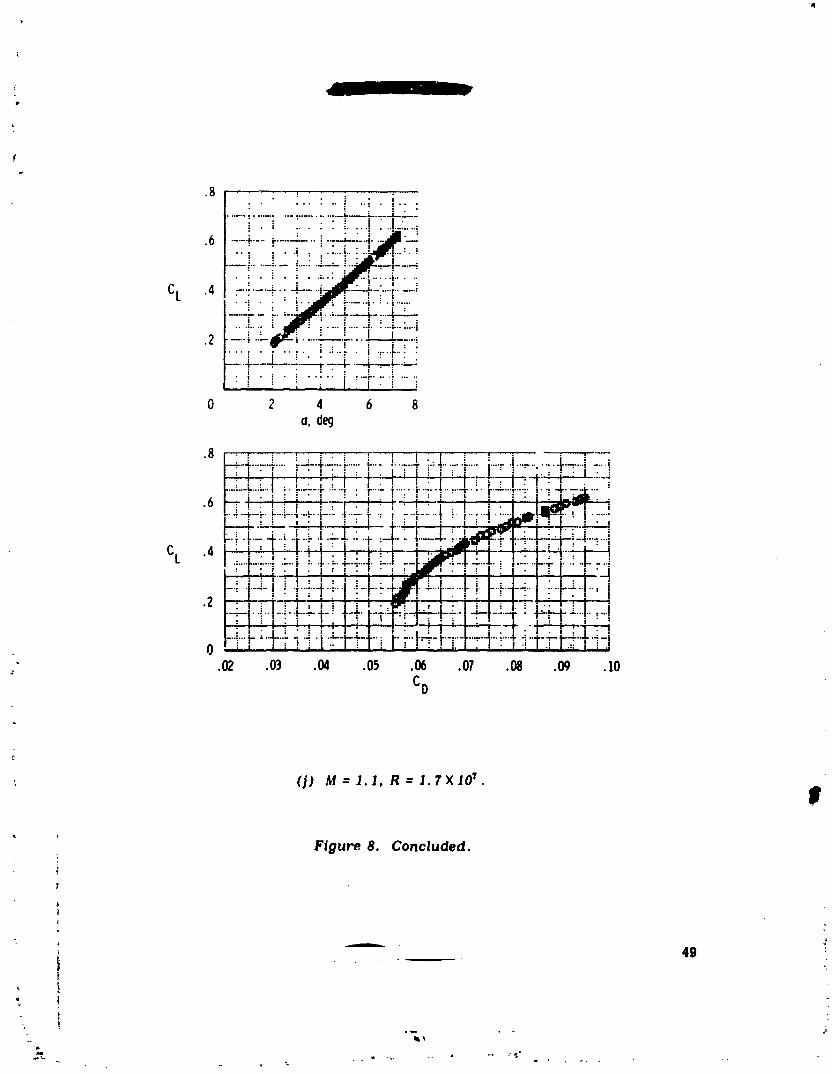
: (])M=1.1, R=J.?XJO T.P
Figure8. Concluded.
L _ _
+ 49
i
1979024988-054

" "" _ O
. @F'l_tu'e _. amrlpionc-n_aria or'og ¢horu_ler'l;/i©a at on altitude of13. 7 kilon_tors (4S.000 f_U.
| ,_
-+" liO
_" 5,1
t
] 979024988-055
1
{
L
.8 '. i : . i • ; : .:-' I : ._ _"'! .... i : " !.... i"i ;":"' !"--T-- " ": .... -............. ..--• -4 ......
• : i ! _ :_ :: " I ,
.0 "' _..... i • ..i." .._......!.-..-...... =-_,_._.LJ__-' '
•• ,I.-_--_I • I , : . ,
' " :....... : i :"i';"! :'+'"""
CL .4 .....:'T....... -T":. i-r-;."-_ i',--+,'4--.. ;......... ; ,.
: " i :.--_.'..k._.-,--:.._'i"!.... i'"!_•....:" .i ' i • " ";: ; " • : ;":"': 'Y :"": .... I :"':
.2 _r:-_.:.t--t-.._.-t_:.t-_-_.._, :,• : : : : : I ••""." ! " " .... ! -- "; ....... "-.'- t'.-:. i".-_..-_-. +_L " : • : : , :-. . • ..... "?.-...---,p%-_...-f-;. : ..k-..,-_
• : : [ I .'; : • f." : l ! "" .... !....... :'':' :........r ....'" • " : " , I i : I : ,= i
0 2 4 6 8a, d_
•8 _t?_.4-_,.:1_:_r.,__: ,:: .
.6
cL .4 ____.,::...:..:.:
.02 .03 .04 .05 .06 .Ol .08 .09
CD
_L
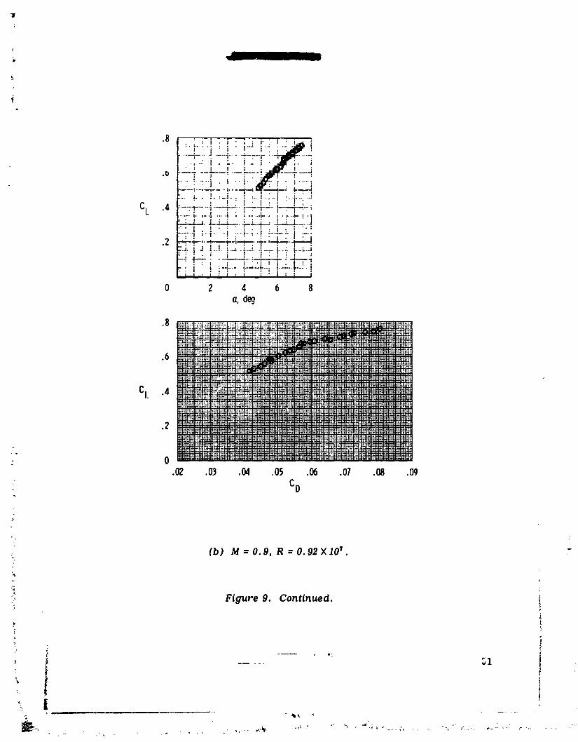
(b) M=0.9, R=O. 92XIO _. _
/
." Figu_'e 9. Continued. :
; I
..... _1
1979024988-056
l |1 : ' - • • • "J" ""_.""1"i '._"-:""__"i" +'""'""""'":"."--".'-4-.+-_,..i--.T.....+-i.-+;__....i:..,i...,b. .u..",,'I ;...i.. :i'...i. ; ' : ":I
.6--:-+-:-..+...i-.!....;..+....l__.:i•..;...t....!..+.i..__._-t.y::.l_+""+.......°+" ,,i:WN+..,....I.-:!::-.!...:i..::!fT: :
CL .4 _'--. "'+"..................:---i..--l..-.+.--.l...i..]. i .'..!.:J....:i;:..ii;! i:-II • : ' " : i i . :17 "!:. ": i":1-.,.'-'+---,_.-I--_---.,-.-,.'--.4-,.,;-._.i-+.+..,_.-.-,
:"_'"r .': :1 : I : _ ,r..:l.,,.J:..,I,.i..:,l:. ;"11.l....i..:.i...I•.,.j_L_•2 ;,-.4-'-..,-..,..
+:iI i HJ--:-.F!:i::i.:!-i:;;.l:.iLi:-=4: ..: : : : "" J :. "'T--" :.-I....,...,....+....,...._...+....:._. :...:_..,
0 2 4 6 8a, d_
•s , ,.+_ ....j.-.J..-.j....J...i.,i :l."i _ _;:' '="'....." '................... •--.-i:-,--:-_::l+-.i.._::.l::..+...,:+_+::_":..:::;..I_':rFi'::!N:.I:::!::_:::"+'_+"-__....-..-,:._":u*_:.__,"+"iI...."":'"'r:.... i"m" • ';;.:;'"'...,;.:.:";.:;--+.:..:,],..!__:..,. ;. :.:+:..:..._..::,..:.: ....... I r:::l ......... :-:'.":ii:..'..:E..... "'1.... '......_......"-' ...........-+:-:"++l; ::,,,.f.,....,-;+::T+i__,: _._,:_+++:,::t+::++;k,!:+_
_2
-:g:i!-E..":.:::,::::,_.:H:_L,m:ii _! +_rr:i+:l:m ';:_....:_:,_:'.'_.".':"'" i ,.._k."i_ii.-.'li:_: :_'l .: ii.'.'_.':.l.'-:k:++ _:,+++_;Im+.:,,::.b_i,l,,k.,,_,+_,,_• '"ill::; :'.1 ":i+":: l j.:;i:'+.... +:;|"• ::.I'::'-':.: ':i" ::::::':",;+:,,;+:z ++.!m+r'_m_ "_: _ :_i!.'!;_'.:_ii+::i...... : ::: :::
: .02 .03 .04 .05 ._ .07 .08 .09
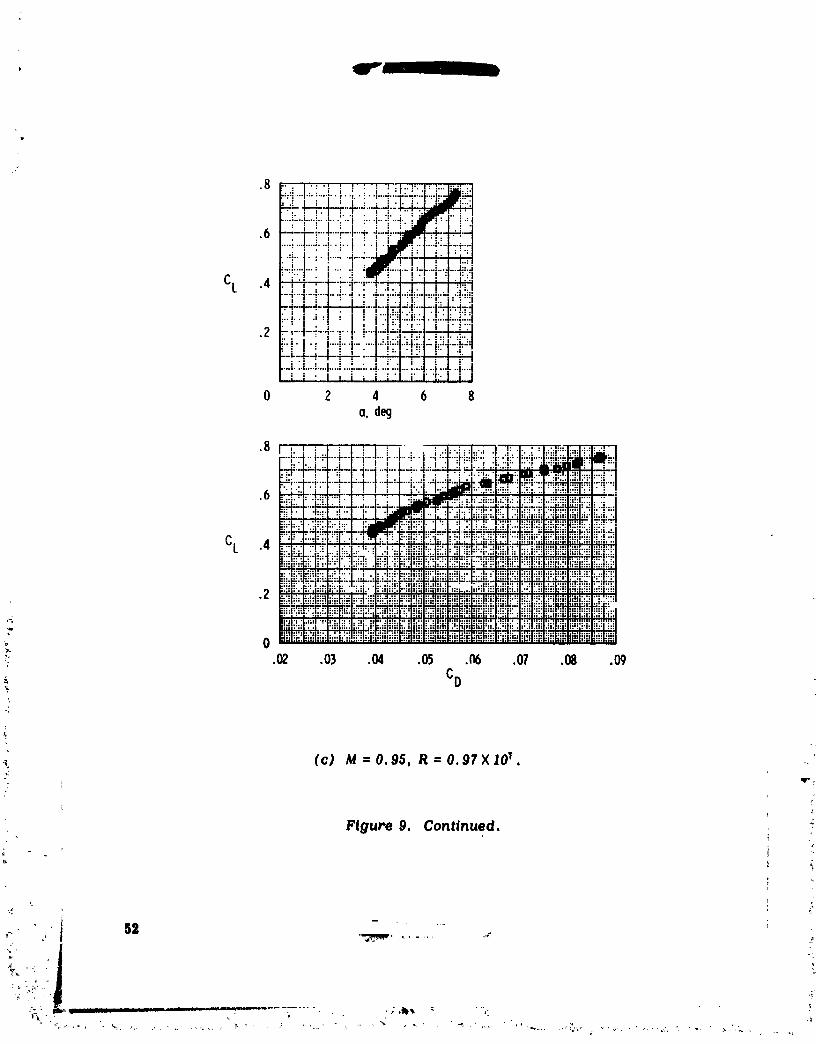
(c) M:0.95, R=O. gTXIO _.
:: _ wr.:
FiguPe 9, Continued, +
,+ 5= " ....._++ .+ ] "_:" . ....... .+, ++_
i_'
:-;-:i:J_ ++._++++k " lint,,'-+,- ......... - .........._ , - • +:,'l_'+,,. +_ ""_-..... '_
• +:_l_:+-_, & _ + +,_ • +, + .,* ,_ , ++ _ -j+ ++++'_ ,
"1979024988-057
!
D
-dl'-:.......:. .....t ......i:! "•6 ........! .... !'-. ".• i ......i" • '" --L...._....+-4..-
i i : i . • _ i i : """." i " "i"": i "'" _'" ' i' _ "'" : .......................:.:
i " i " , • I " I:.._._.: ,,IF_... i..i!:.'CL .4 .........".-.....i........i.........L.+.-i...-..4--."--4-...--;
I i: _"..". i: !:. i:"!"-"!'"-_........i..-.---_--..i--.'.-I-.-..l-,.-h!'•_'i'_I....:i ! i'._'i-i!"h-!
•2 .... "-"..... .1.... ,....:._-:..... l -:..--!....i..4--_4i.l_ i 2L. i i ii !....i.!4i ! • I : i i : : i ! i I
•":_"!......I "_'"'P":.'"_'-..'-'i"-.'"!...-_--!-,.......-.,• . . . . i . ."" I" • ;.... I • ";"-:" i ;'"'i--'._ i -",,,i
,. I. • : : . . ,
0 2 4 6 8a,deg
I,,,". '.' .,.. ",..:,!:-:l.:::':.--.._-,l---:_-._..:_-_-._,_.{,_:-.:_-i:4_ __:'"" _ :' ! "'T"_ ; I:"'' ""1"'!"r "!'"I"T".'" P'-i--'" :..4..._a_.._:." .'L-_--___-_:t-_--,,--:_._t--_ Ii_:7:;:_:_,_-i:-;::_:4..: i ..! .i,i....i.-..I..i!-.-._-._ .._.4...!...
•6 ....i- ,J"-i--i"':i-.1-J'4" ':-_ -I'_'_ _- .-:.:_'-'_':-;l;j.:"I:.r::,"-',._?".I'_ i "' I :'i _ " _" " i'"T-'i'"_"L."! "iT"":'::"i""i..... K_¢.._'i-i.! :':'''':_';'i.....:..i-':4:iiii.-_: i_::i..:--i.:il.+.i.-.-I-..i-l._i
!_12:_ _!i_T-_ .-..._.,..,::.:,m:..._ i...i.i.,...._
-:" .. "I..'_. _. I ' • " ..... ;;.;. ; I
;X; ': 2 _ £i.::..:_-.i-_:/..i_q.;:._:;i;2...4_i_I........ _... _.._,.._,...._ ;i'.=_:. :i:__I:,::i;._i_.:::r....._.....:.i:-::I_"" r "'."".I..i.--..t-....i.-.t_:.i..:-::._..-_:.]':.i_!-i!:..'_!: i J : I • . / : /' ": .: .:'" " • ,=_• !- "r!:_":--i-_ _:__,._ :.-.-i_ _.-t•".... :... I : L, | _ ! ": :..i :i:::' : .[::..:.":._::..::i ." ..:.: :• i ': .::1::. ::::'.. ::'P::::::::::.,_.::.t....... !..... i.......:i-:. ':,,i_':".!'+.',i::'_.:;;":.%1".'!",._::.!..,.I...i::_.:_I.._..%,:::_.::.-,.,,.:.._::_;_:t:_!ti:_]i{_-_i_i:iii#!_-:!:
,2 ,'_'_ ' :i ] ..[... ."., :",. :::_, .:'F=:.::Ii:.':i..._.._::!-,_;_:_;__;:I-!._...:.:-,:l._"""i_!_ _{ii_;rn_l:i:_i:R::i::i._'il:_-ililtl:i_!:::_!_;i_:iiii!_l_..;i_iiili!:i_":'.:'.."."::....... :"':":__-,"".',':_..'.1_!:_ii::,_:.:"".._'.".'.."_I'.-!:"I':L""._,i., !:.,',:,'.r"_:,',_:.,r.,i., .. '_'i,_:_:i,',r:l ._:,.,....I:..,."!..-*."":','_...:,:.:,.':'l":..L,,!.!_.:',1.: " ; |:! ".I ", • .I,:::,II .Iil:: ::..I': :'I ::If ':: ':'"I'"'" ' • i • !'I; .'" ,. "::.I: 1', l:'II:.,:, :. ":.::i ::,;I;i:.,_;,t:,;,i....!,-..I..:._.,.-.__i_.,._.:._,_,_.-_.:,ti_i_i_l.:-.u--...i:_-_ :'.i__!_ii._i.i._ i_
0 i!{!ii::I •_1,,,i ,,_,,I , i,':il :::1811,:!i4i] ii._i!::ii!:i::.:iiI-;..!:d/.::.::,;: :_i..,_;" .:if,:iil:Li::_,'l:l:iL:a:I:: ::":,:!
; .0_ .03 .04 .0_ ,06 .0_ ,08 .09 . ]0
C_
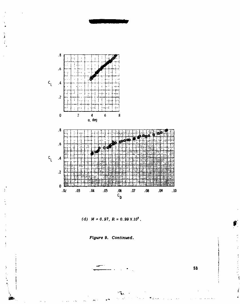
" Figure 9. Continued,
: /
=d_'-" " ' _
i 1-
1979024988-058
_ I
CL .4
.2
0.02 .03 .04 .05 .06 .07 .08 .09 .10 •
CD
(e) M : 0.98, R = l. OXlO T _ _"
Figure 9. Continued. :_tov*
-p
.-'3=4
I
1979024988-059

• i " _ i [ i
: . : : i :...... ! .............. .."":' "_--":' ' i--=' "_
..... . ....... .--•....,-_:
.6 • i ..........".... :""
....!.....ii ....
CL •4 .......? i:- [-_iYi
• .; ] , _.. _ :.,i..i.
0 2 4 6
a,deg
.S • | ,
• : !.{ .i: i ..... i. _.. ; .., :,.:_ : i....i..Li. ".'......l":'"i: "'| • i" I : I : . " ' " • '...._.....4....4--.:-._......._......'-_.-_-..-L-_..-_-.2.-_-:.-_.:'£-J• ! i . ! : _ : _ : i : .... j ! !-...] l ; "!
...... t : ' |'"': "s "'" t ........ : .... : ...... t .... :'" ': "'T'"':'"'|: • . . • ; • : : : : • , ] • , : |. : ",
•6 ....._-4....--+-:..--_...---......_---.......-i---. --t,an,_,---!:--.'...-:3•• :.L..i ..j i i _.i • ._:._,_-_...._ • -i.._21:'l " I • : : I ." ] I_I1%Pw'-'ii.i '" ,.".':'1•--'_--| ""_-"_"_' "_-'-t ...... "_'-: .... "_-:.l,,m,l_-._._.,-.-._---I.-.._.-i.• i ' _ : I • • I _. 'JJEIM-: , : ' , , :. I .:."_
..... !....:.:.I ..... i-": ]...... i. _. j...+-b-.i.-..l.:--_--..b:-.L_.l:..:_;;;;icL •4 _-...-i-_..-@-:"--_.-:..._-._.._-W.:_-g._-_:-._._l_..._.i..." "..i...._.j_lfi.l.:L]:'.l.:.i..! :..i::.L:.._:.l-:_!:_L::i:.21:_:_i_
.- ' .....J_.:_ "_.;, ' ...... |:'" "i-" _...I.._. ' ':'" "J.""I-:..-r- _ : ! • _l.:.......!..-:.:.._- _... :._:.:,_._:.'.;:_
: ..:T._:' ":'" :n.:,..." _."_-_. :. :....:'..,::.:• - .,:::,:,,::":: ::::::::":l:":i::::::-::N..,..::...--t--.,..:. ;_:. ::._:....:.i: .:_:.,:....,:....:....
:: .02 .03 .04 .05 .06 .07 .08
-'*' CD
(f) M = 0.99, R = 1.0X10 _. {V
_7
_, Figure 9. Continued.
?
55 "*
. j
1979024988-060
Jl _ I J
.8
.6
CL .4
.2
0 2 4 6 8a, deg
.8
1979024988-061

: : : !"" ""i : : .....: i i'i....: ""! "": "";'"'..'"'_.... ; ..... _..... _. :.- t
• ; I : • : •|. ! "''"" !.._i .... ! :"
.... _....... -. ..... ":..... I............. "_."-:.-"1' ," • _ I • • : : :•:','I • ':'" ' • "" • : : .... i .... i
CL .,.-.._. .i ......._I......,-.!..._dr......i-i, i. : i ...!r " ._'..Hit ._" :I" " : • ," ," : I :I-;: ' ! i :i---..--+--.--._,----,----_.-:....... +......iI • I ,,,,_dJ[]r. .: _ : ! " i i i : .I-_ :_-" ! :! ......._.i..!
• " I ."_" _ T --= "?"-'_"|'" " ""1• . I : . | . : : : ,'
: i! -T r! ....0 2 4 6 8
a, de(/
.02 .03 .04 .05 .06 .07 .08 .09 .10
CD :
._ (h) M = I.I, R = I.I XIO_.
r:_ Figure 9. Continued.
t"
-"_-..... -- ........_ 57 ,:'
1979024988-062

.6
0 2 4 6a, deg
....i..:' .-...'....-_.i. • ._.......i-.-:.;..b.,.-p.::;.-I...'_.L..L.i.-- -I-:-:i._:.li.-_._:::i -'i:" " : _ " ; : " ! " : : : "" i ' |'': I, : : I',: ,,,|: :""
-h ..-J--;_.---t-_-- .._._....--!_.-t._.-.!----4r_...[.--_
.4 -.t_ ..-_-i-.:-..J-;-.t-._-._--;t-_-. t.-:-__4--.-.-..'."-.L.I--:-".-..-:..-i::::i=l-'.-.-._+-..l---.!-.-.i..__.--4---4_i
CL : i " • I : ; 'I "' : I .!:!I • l'.dIqq'.. I.: !:: F_:I ...JI:'-"_.'l"'_:-_"" "--"_"_-"-t'.'-'-1-"-'" "1-_-""T -" ,_-_.l. ; ..I . I _l...... .1I" : : I : : : i '::" I' :: :'. i: I':" .:' : .i:.v.:i :v':"" ::::I'.:'l•" :'"t' _"':'"".""'"":-:'"':""!.'"-'F'"':"r-r."t""_:.!-..-_".-.'" ._....--.t:--..-:• : • : ' : • ." : I. : ! : ." .... . _ dim "" " I : • I : 1 .: "'| " ;:: .i
.2 • i :" ! • ; '----'_ "| .i.l..!:"r.. _ .II_PJ i !. i: ,..::..i:..i..:!.::::.:!.." "".....""I ........ _ "'" ......I ...................'_ .... ."'I" .'_'-:I'.':'.'"" I . .. "' "I .. "'"" "_'.'-t'.- 1""._.. ......_..'_=. :'t ":'-'_.-: :. . • ;.. ...... :..:_ : :] .....: ,I
: I • .1 " "1 ; I..'.l...I. : ','":. I " | i I" :'. r :'.'1"::." I
.-:_..-".... , .... :--....'-.!.-::"._i-:! .'. ":i".'+' :':;'|-;-----t.... -I-..---1..-.:.-!..-.-.:...4_-;.!0 ;.. i _ ; i I _.i': I i..:l'...._:l::..F:.:v.:.:! !::. i.i..:i.:T.._"r'.l:riL-!i
.02 .03 .04 .05 .06 .07 .08 .09
CD
;m
(i) M= 1.16, r =1.2XI0 _.
r Figure g. Continued.
j _
1979024988-063
F
0.02 .03 .04 .05 .06 .07 .08 .09
CD
(j) IVl= J.22, R = 1.2XI0 T.
,3
Figure 9. Concluded.
+++.... _ 59 +,_-+_+ • + ++k++ _' + +_ +++
+_.+.,++ -++ ,++,+, +,= ,_+-,T+ ,+:
+;;++,++%+_+ Y-+
p,j+_ .... ++,. ._ ++++_............... +.++<_+++-+.+---_++-:-+-+,_--+-_++.,+.,.+ ++,+---- ++++.+'+'
1979024988-064
__ _. 111
III ii
I',I } _°, _ _
I I l l ;
60 _..._...__..........)
•
i, _ - -, .......... , ......... ; _.i ?
1979024988-065

i,m
h, km(it)
1.0 -- _ 13.7(45,000)..... I0.? (35,OCO)_--- 7.6 (25,080)
M=0.8
.8 -- / M=O.9 M _0.97
/ /,,,F// //.6 -- / 70 // /
CL ;
ql, n i
,; 0 0 0 0 4 8
?]g
Figure I1, Effect of altitude on llft curves obtained _m /qight data.11 - 0.82XI0" to 2.3XI0 v. _"
L-,
ha _ .
k
1979024988-066
, |
]
.....: :, i., : ,:. , [ ; ,i .... i ...:..: .. •
•6 --"........i--..'-:...-........i._' :....- .'.._: " : ! : i " I " : i :
_:_:._--_-! ......:- ' LL-Z ; ::-::':--: . i • : • i • i • i . ! " i
....i" ,' i +" , : .:.... i ......": i";";......... ..i---. ,-:.... .i- .... -_" ; . -....!_.:..._._ ,:
CL .4 ...... i i [ __.-I :L_:• . |
+ , i _++_H__+-__H!" ......... .'-r-----.'_" : :........... _'"; i ......_.......... '...........!'": ....• ' ; : I !
•2 -.--_-. _--r_-'.--_..--i--'ff','-"---+-*.": :. "--:"_....! ........ : i : i i. i.......! ......! :._...'..a.:..-.'
....___-.,.___..._L. _z_], .j i i i i ", • "- " . .'-:'T-'T."T. : .• _ " : ..."...i--.i...:.:.i -..--i-. . !..;... .-...... .i.... !.. . . . .
i I : ; i • ; ; I , ; i • i
0 2 4 0 8 lOo, deg
•_ - i _'1 :." . I ' :. : ' .: , : • " _ !I...... i.....T--_1 ....+-! '+ :_ _'-_ !_ I• • _, . . : . • _ _l..s.i : . -_ .....•---+----_.. , l I-- ......... I.., J: I : • . : I : ' • I . .' . !. " i'. •....._.....i .....,_-:!....._ : _._-_r--_, ._.-_-.I..-,::-4• ; ,i,Jl., " " ;. lll_l I ! .' " I " " ' : "" ..I.6 ....... t; , I' i + J ' ! :.8,,+ _ .... L+ I . • I + : _
...._"t + _:-I :r_/_ i"_:':-:._-f_'--M---i'-r-!-. : , t. _-i'-_. _.....t:_-,::t r:rt
Ck .4 : l i i'm.-_'..,!_ j I-z k.._-_..-l:_-l--:::i:- _EJF-:I
....._-4" F-++-_, 4--_-+4-_ i-_4z:_u: I ! : : I : l" ' , ; _ " i :" I _ i i-.I ": .r.'! ..i... ,: ":i.2 i : J • .I : 1"i I i.J ! : .." _ i I ..l'.J I.i'I'!::F:"t":
-. ;..._r-"= J"-" 4"":"'-_-'- -_-'."=-.-I'.._" • -_:"_,e-- I.-..--+-'+-:4--._ .- ;.":. ",::';., !:- I ; i , / , i. i _./ ' _ I" I i .t .,,i i' :!,_r.i:::• F I _ _ .! . i. : , • .I:,: P:. l..: , ""! :.l :" : ' " ::.' ": l .";
_: .02 .03 .04 .0_ .0_ .07 .08 .0_-_" CD
(o) M = 0.8, R = 1.3XlO _. _/1
_ Figure Z2. Lift and drag characteristics of oi_lone modified with oreo-eulefuselage falrlngs, h = 10.7 kilometers (35,000 feet).
+,
t
83 ;'
1979024988-067

, . ;.. .l .... : ....... I-. :.-J......
........_ :+_-_-_• ! :_ I_F ;-i !
•_ _.-r-_ ._..-]:e _..L. __Lj_ _L_2' ___]:_L " " I ' + : J ' :
i "I_+.I + t ." i : t•2 .......-t---'--"_-"-" .......-I.--_• . : I f : I : I , i
•": I".......L...+._.._."'i"'.+'"i'-'"!. ,L + [ _ [ , , .'L'+..I:':t.-i-..;i i.-!..L:.:• . " : + : I _ :
O 2 4 6o. deq
+
+ +-J-
.4 .k__-.i---,.CL
: i i I
CD
Ð$(b) M=0.9, R=J.4XJO 7.
• WFigure J2. Continued. +
• 65 _(= ,_ .......
+'.............+ - - , \ ..... " "'.:+- + + + " :£ " +, .... +_+: _++-_+,,,m,_,,+- ,p,.+..+i+e+ +++.+ _.++,+++-+_+..++_++++.+_+_+,,+++: .?+ + + + + "+ +, +_'
i + +--
] 979024988-068
,8
,6
CL .4
.2
CL .4
_ fi (c) M = O.eS,R = J.SXJO_.J
Pdgur_ 12. Continued.
; r
|
1979024988-069
fJ,t,_ ,q ,. ° e,l
CL .4 i_)_!:!!);_)_.._ L .
__ .... .
0 2 4 6 8o. deg
•s))____,__
CL
• '..................:.........................................._i_-_;_;_
.02 .0) .04 .05 .06 .Ol .08 .09
_ , Co!
' )• (d) Nl=0.97, R-" _.5X10 _.
_.:._ Figure 12. Cont(nued.
...... ................ 6_
:_, q • ]
1979024988-070
; rl - I _:
•8 '. " " " ; ;" I : '. • | '_.... , . L ! '........'...:..._,._.._._..j.;_., • ! . -, • , • .. _ .. ,. !,All J
:4: I.... ,: L:]_! : i . : • j ' j " • .| ".
• ..._ ....! ....i .....i..._.+.:+:-_- i-_--_-___iJ•.: ' .... '...'..'-.," .,: .i. i ._ , -i :]
CL .4 ......._-'."--. .-_r--_-_ .,'. :-.,'..:._J.....i...i...,...__.L:. E::J" • i : ' ' I :.. _ :! "l":i""".:.'i_._._.._+_l[r__': i.".!:.]• i': Mrs.. l.....'./i..._..-..:.it__:f....,.L... !"i "i_ ..:-!.."L.J
•2 "---_-_..---_.i-.-+-__-F--._-.- It " : 1. ; : ": • i :. I.. •'" '_:'" e"" :"" f"":'." • "-:-'"}" --" '_..- ; .. ,--.:! "-._-..:}" ...i
--,:..!..,:i-_- i• _" 4 ..l....._i: ; : I" :. ""i /:'-,:: " I-;r_T_-l-:......--, :J,-_-!,v-' ,.: i i : ,'. I _ .i !.1".; i
0 2 4 6 8c, deg%
.8 ___ __.__I_I_/._,._I,l_i_1_]_...._ _i_ ...................................
_,_,. ,_-,,_ ........... _._ ::::::::::::::::::::::::::::::::::::::::::::::::::::::::::::::::::: ........
_, .2_:.: ..................................._.__..._.._:::::::::::::::::::::::::
_£'.'.:E,_i £:E.£:B"..._:._iff _"..h_ ::::::::::::::::::::::::..;, ::,|...=...,::_ ::.... :::: ;_._::::::
.0) .04 .05 .05 .07 .08 .0_ lO :r" •
* Co
(e) M = o, gg, R = 1,6X10 _. ,_J
,s°
Figure 12. Continued.
!•
......L j
1979024988-071

-i
m
.)
, .6 . :...i.,.:i: i....i._:.i......,,r,'.:.i......i-.-.+.-._-..-l-.--.-i---+.-.ip!r.-.."...-i--.-,-,,. :. i .L.!. ,i....i..._.l...._.._.....k.-,..L._..i! I •..:. : i "_" i : ! _ '.....I .....i- ,=--+-i-...-t..IFl.-..-.+-_.--_.....--i: _ J _ / I..I._.L...N K,.i._ :!/ _--i /
....... ! "'" l" __:_--,l" -"1 .......
cL .--+-4..--i__" ...-:--:_--i-G-i: .!. '..-_::.'.:.:1.!--.!'":.!'--:i I .: ' ," "::'. '.: .: :
• I : I ' I" • ; : : • : • ": •..... 1,.-i .........,_,.-r,-.,.-,,,_.,--., 1-.-_,-i,....,.,,,:-.I-:-i-.",,-i
i • I : : J " I : ,ILl " :.,;
TT! +"I'_ "i"]I:TII":!I0 2 4 6 8
a, deg
"6 +" I ' i ' i : ' " + : : : i +:'J _i i
....:" -J ' • "#-'':'"I'"':' "-|::.L:.I....+ .i...-:...I .,_ii nl ++ +i i
__,i_...__i_i': l: ." .: .[..:i I:'i"I. i i._DIF
•,i .-...i_.:_:. _-!:_i;_•i .... ". "_'-_--!:.':'"" ':It..i'._':
CL ::---t-_il_. t .''-_t-'_ :: i.: .+_.:'=•4...i._i •-4...'...._.!.:i.i:;_7_-.l:::ii"..;:l:[;l-.:i_:_i__ ..... :i i' I.; !-'! :.L'.!..'i':.:l. "!."
.2 .-_:T:!_..i"l;::.b.:+,i.-:i.]i_i:t,:i!:_;;:_ ..__]._._..:,_ !_.., : i ! -.: '.'_....... ".: ""::":-,:.F,.-,: ..<..:0 ': + I _ .I"i 't :1_r._:++..i..:"i..i:..i r...
.05 .06 .07 .08 .09 .10
CD
_, (f) M = 1.I, R : 1.7X10 _.
Figure 12. Continued.
)
t {
\V/
ii
+lll_,i r + ...................
"1979024988-072
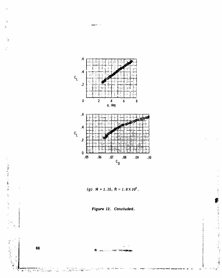
u .......
,v • ; :" ; :. |. : t :"l: _ I'" _--' :...;..L..,:...i. :...:. ; .... !. !.. '.! : " i.-i• ! : .i .. ! ! _.. J • _ : :
..... ---:---I ..... "_-":'i- .... __-.-.i
.-r;:-
..... :i! :.-_-i :.-F._ _.-,-!cL ....._:--!-_+_
•: !. • ! _1_.......'.-_.l.......i i-+-: !• i : : ,_: "_ i ; : j.: i_
.2 " ":-,,-"'"--"t "'T: 1--'=',-:_--r--i_• J-4- !...-..i .....,_..... _..i,.-.! _-..-i!: 4:._L--...L-J.___.,' ..:j--..! _: _._J
i • ,,',i i ; E." II :'t,I :: t" I,"., i• ._. : " . 1 .: i'.:".l], '. • i : i : i : i i _ i
0 2 4 6 8a, deg
'-'"-r_-+ .->-_.!.... i / _ .I :: j_ !.._,iOP'_..._-=.i2-.x-r.,_._i_..._:..-'--1-i i I:-_-i..... _-r4-4_.-• , ._..r..r_.
.4 _ii: i_ _-q..._!:..'--.*,.+-t_A...-_.--IcL __ _-_:__q.i;l;,-__ ,..---.t_i-.:4-.-..-!:-:_i:_--,_:J_-.,.:--.--,
o-',.":I.! 7• _.";'.. . ,::..:" ":... ".',:." ." ,..I
•05 .06 .07 .08 .09 .10
%
(g) M = 1.15, R = 1,8×I0 _. :
%
i Figure 12. Concluded. ;
i :L_;
.1
F
I ] <
1979024988-073

Area-rule].0 -- fuselagefairings
OffOn
'" -3.8 M=0.9 M = 0.95.80.97
.6
CL
.4
.2
_ I 1 I I I I= 0 0 0 0 4 8 12
_- o, deg!
_' _ (a) Lift curves. _'i
, !) ._ Figure 13. Effect of area-rule fuselage fairings on airplane lift ..
! and drag characterigtlcs, h = 10.7 kilometers (35,000 feet).
,i
" 1 ....... 69 ', '_"
]979024988-074


Area-rulefuselagefairings
i Off --"°
i On ;.-_ _"_
I
' / f ,,4"
ir / M "/" /7
( M = 0.9 M = 0.95.m
M=O.8
o_. I I 1 1 1 I I I•02 ,02 .02 ,03 .04 .05 .06 .01 .08
CD
,';7
-_ (b ) Drag polars.
"!
' Figure 13. Continued. "
t
_._ ?1 _"
j-
............ _ - ;.zc: - _
1979024988-076
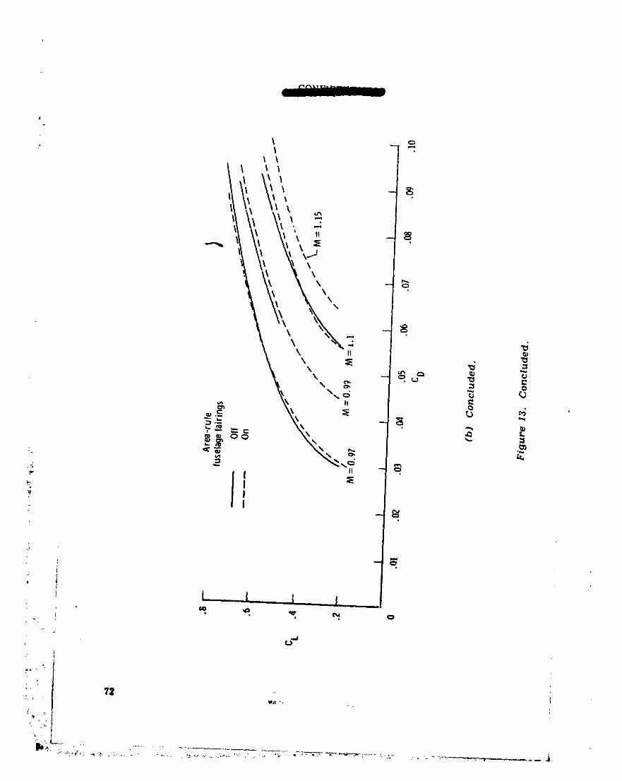
1979024988-077

73 _.
1979024988-078
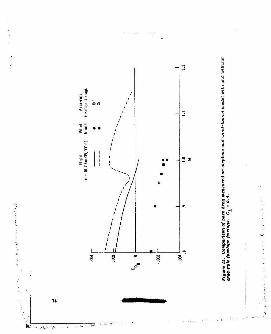
i,
0
_._.E I='= I
_ oo / o
_ °-- / *-
_ / g.c::_ • 1 / "_--, ._
/ "o
"_ I I•--_"E i / II -- •
_ 0 0
II '_'% I 0
i j _
/ E._ -
• o, _ II
_" _ _
:, _ _- -.
,- ,I _ _ l,_I__ :
2e
, 74 "*:
,°
1979024988-079
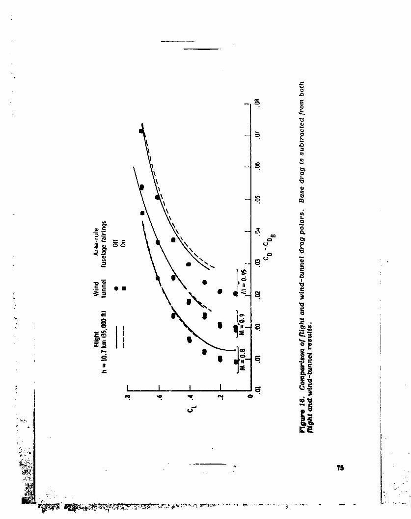

I
-- (3
° 1.\I
L. __ ¢_)_ , Q
•=- -= • m • \,, "
.T: I •
L
U
76
I
] g7go24988-08 ]

,I _, qwr-
Flight Wind Area-ruleh = 10.7km(35,000fl,_ tunnel fus21agefairings
• Offm .... • On
•8 -- M : 0.97
M:O.8 M :0.95 // M : 0.99
// /,I ,7- /,.6 • / M=I.I- / l,' .,7 • /" ,,
, I V,,/.,t' ,f! / ,Y , ,Y
. I I /._- . / _,Y , ,Y
.i,/ v, ,,,'/.Z - / ///' ,I/"
i I I I I I I0 0 0 0 0 4 8 12
,7 (t,.
,_
. FlguPe 17. _ompoPf_ of [light ond w|nd-lunnel hor/zonlol sloblllzer defle¢llons.
'_ _
: , - i i ii ??._.
-_";_ _ ........... _ " - ........ _: ...... '_k"__ _.2 :" "',?_ - _ . .... >L : ; _",'.'-_'_"L-_"__. _ _""'_:_._ -_..
1979024988-082
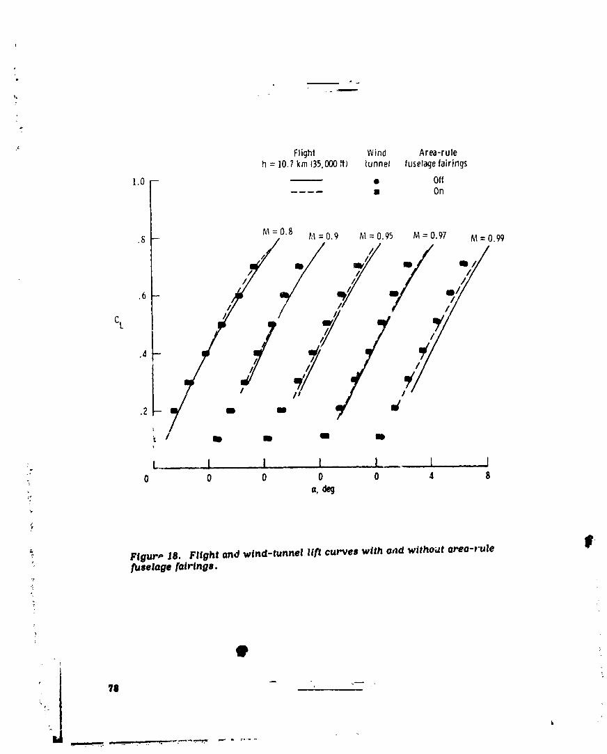
FJight Wind Area-ruleh = ]0.1 km t35,000if} tunnel fuselagefairings
].0 - ------- ii Off.... • Ori
.8 kl --0.8 _,4= 0.9 hl = 0.95 M = 0.97 M = 0._
,_ //, ///J J./..+ /4 .,,/-/ ,/
Cl
.4
.2
i l II II II II
"+- L., I I 1. ._ I_ . I ]•_ 0 0 0 0 0 4 8
; FtguP,, iS. Flight ond wind-tunnel lift curves with a_d wlihoilt elte-rule _'fuselage fo|r|ngs,
B
?111 - .,-- . ',7_!
1979024988-083
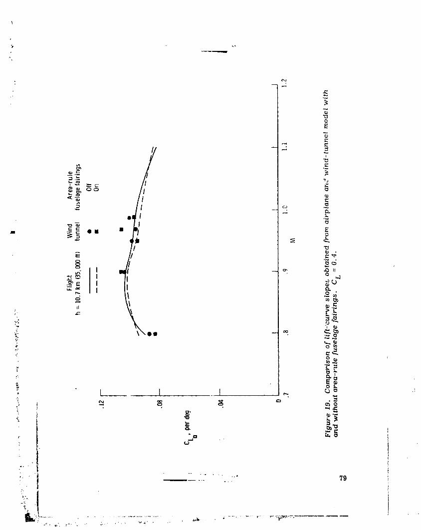
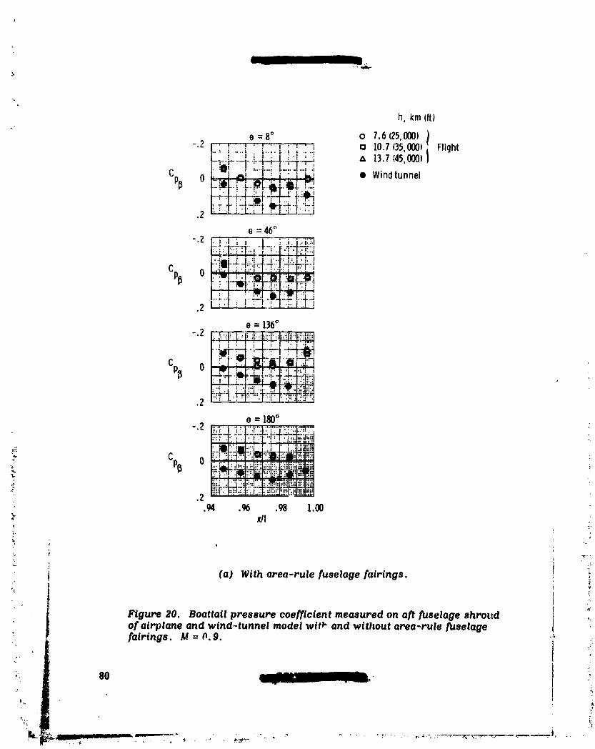
l 11
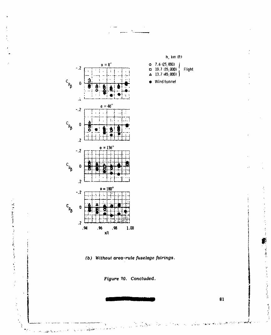
t
h, kmfit)
e=8 ° o 7.6(25,000J )
-.2 [, i. ;. i : i. i- i o 10.7(35,000)i Flight.......; ............I......._........i....... _k 13.7(45,000)
Cp_ i • _ • i.. ! .. :.:, _ , _ • Windtunnel,m"U.'•--i 0""6 ...... i..... ,--4t-
• • w' 'I'! •!": "'.k L__- ............... -=._.: :-
O=46°-.2 _. ;.._ J ....i.i
..... ,.... .......L._._;......)........
e = 136°-.2
c_ o qs:_I_!:_"''_:"; _. " "l ram?'• ..:.::_ , :i . ,:i
I • t ) . •:""" !';"1 .....I' ";
•2 ',_.-.L.----L..L-._ ,
e = 180°
-.z ]....;..=...,..i.:..]..,::..I.......I.._...il J ;. i_ i) l) _ °" r'"'" -'I- _'| ..... r.... "1" ".'---I"'".--" )' / 1 • t : , • l: I : :l
_ Cpp r" _ _i .......I.................h-"
m'_" . ,,, .=.l.l! ,.'.1i i . ' =_ |" .; . "'_: 0 !...I.'...lIB'..._jL:, ..i-..l:_..1
'f I i ' I| il L I il-_,:.i"_ [iZ- I--:.,'r-_'.;,'! '-,_ .zr-j:r_I::__,-_! : _:"" ,oA .96 ,98 1.00 : ,_-- xll
.+ (b ) Withoutarea-rulefuselagefairings, i _"; _ Figure _.0. Concluded,
I '• 81 '_
• .j
1979024988-086

pl
I
] 979024988-087

o Flight
Wind tunnel
_ ] w
Cp 0 _/
.I - /
.2 1 I l I Io .2 .4 .o .8 ].o
x/l
(a) M = 0.8, a=3.3 °.
-.2
.A
-.I--
Cp 0
,l
f,,z ,, . i I I I 1 _
.. 0 .2 .4 .6 .8 1.0 "" xll
-_ (b) M = 0.9, a=3.1 ° .
"_ Figure 22. Surface-pressure measurements along centerlineofarea-rule
fuselage fairings from wind-tunnel model and flight tests at C L = O. 4.mmr,,.s...._.m
: 83/
]979024988-088

0 Flight
-.2 - _ Wind tunnel
e
-.1 -Cp 0/
.! -- 0 O/0
.2 I I 1 i i0 .2 .4 .6 .8 l.O
x/I
(C) M = o. g5, (x=3.2 °.
",3
,.,. -.2 - O @0
e,
.,; Cp 0 /
/k
_ ,2 i I I I J '- 0 .2 ,4 .6 .8 1.0;;:: xll
: (d) M=0.98, a=3.2 ° .
Figure 22. Concluded.
84 --
1979024988-089
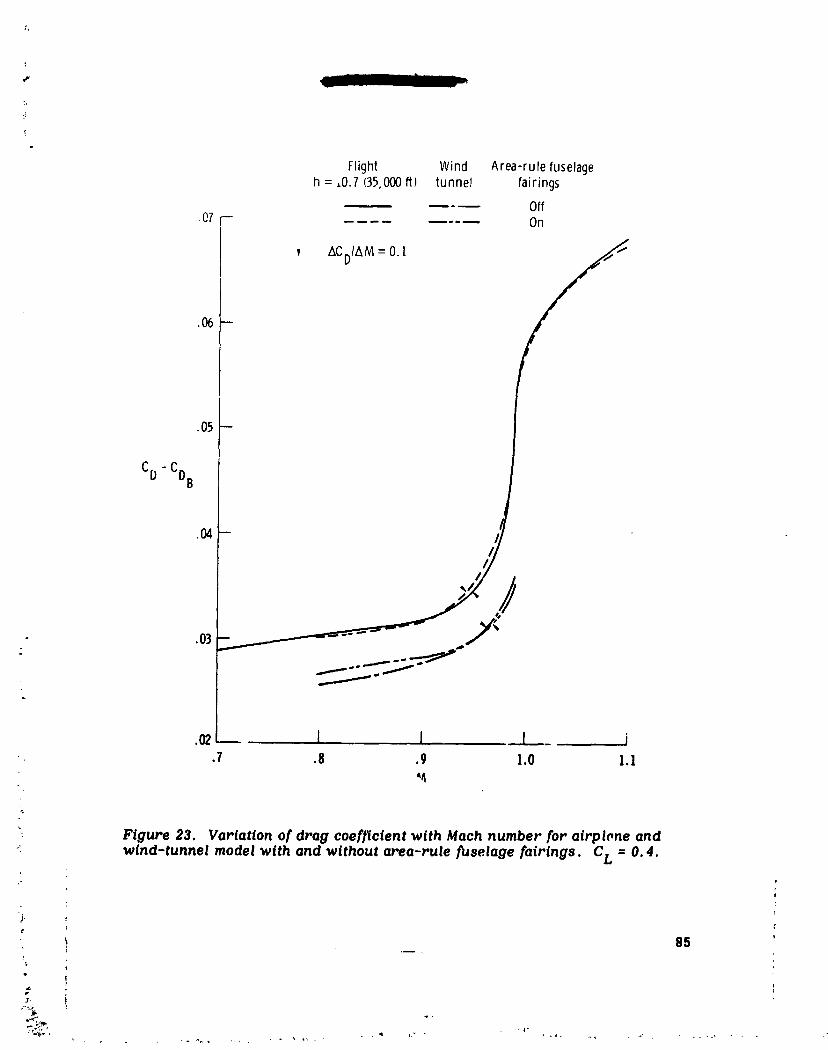
Flight Wind Area-rule fuselageh =,0.7 (35,000ft) tunnel fairings
Off
.07 _-- .... On
v ACDIAM= 0.I
,05 --
CD "CDB
.04-- t
.03 _,._._._ ,,
.o2 I I I i_ .7 .8 .9 1.o 1._
_, Figure 23. Vertation of drag coefficient with Mach number for airplone and,_: wind-tunnel model with and without area-rule fuselage fairlngs. CL = 0.4.
_- _' 85
P
_ t
1979024988-090

2 r
• I0
Z_OB,d_ -.2 I
-6 1 ', I-2 0 2 4 6
an, g
(a) Nose-boom bending corJ'ection.
-_'_. Withsideslipshaftandvane
WithoutsideslipshaftandvaneAa, de9 "---
.4 -
f o I I I i•6 .7 .8 .9 1.0 I.I 1.2
M
(b) In-flight angle-of-attack calibratim..
• i Figure 24, Angle-of-attack calibrations applied to flight results.
t 86 .e
, [
1979024988-091
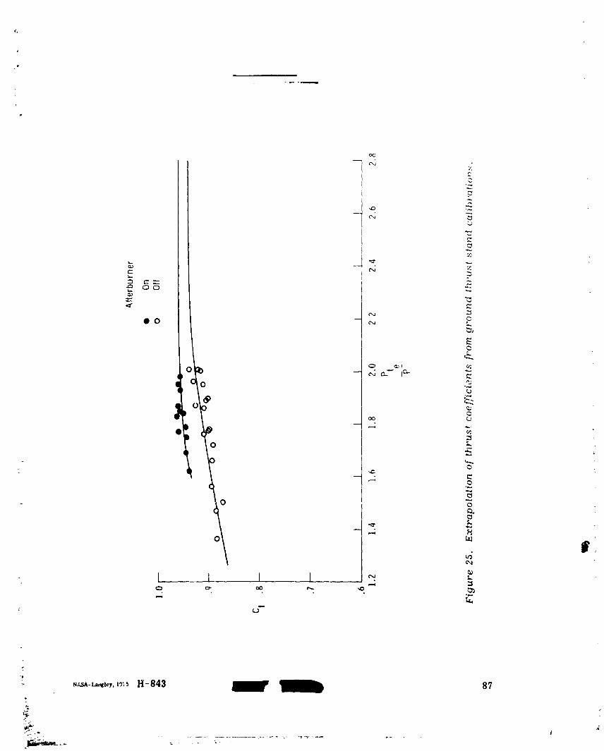
f
,,,t,.r_-L._l,_y.X_;SH-843 87[__J
1979024988-092